PARTS, SERVICE & REPAIR BULLETIN
64
PARTS, SERVICE & REPAIR BULLETIN PRESSURE REGULATORS Manual No: 0056-2690 Issue Date: 22/2/2018 Revision: AB esab.com
Transcript of PARTS, SERVICE & REPAIR BULLETIN
PARTS, SERVICE& REPAIR BULLETIN
PRESSURE REGULATORS
Manual No: 0056-2690
Issue Date: 22/2/2018 Revision: AB esab.com
!WARNINGRead and understand this entire Manual and your employer’s safety practices before install-ing, operating, or servicing the equipment.While the information contained in this Manual represents the Manufacturer's best judgment, the Manufacturer assumes no liability for its use.
EDGE Series 2.0 PRESSURE REGULATORSOperating Manual Number 0056-2690
Published by:Victor Technologies Group Inc.2800 Airport Rd.Denton, TX 76208(940) 566-2000
www.esab.eu
Copyright 2018 by Victor
All rights reserved.
Reproduction of this work, in whole or in part, without written permission of the publisher is prohibited.
The publisher does not assume and hereby disclaims any liability to any party for any loss or damage caused by any error or omission in this Manual, whether such error results from negligence, accident, or any other cause.
For Printing Material Specification refer to document 47x1909Publication Date: 2/22/2018Revision Date:
i
Unrivaled Service and Support.Every ESAB product is backed by our commitment to superior customer serviceodand support. Our skilled customer service department is prepared to quickly answer any questions, address problems, and help with maintenance and upgrading of your equipment. Our products are backed with the most comprehensive warranty in the business.
With ESAB, you can be sure that you have purchased equipment that will meet your needs today and in the future. Product and process training is also available. Ask your ESAB sales representative or distributor for a complete ESAB solution.
Be sure this information reaches the operator.You can get extra copies through your supplier.
CAUTIONThese INSTRUCTIONS are for experienced operators. If you are not fully familiar with the principles of operation and safe practices for arc welding and cutting equip-ment, we urge you to read our booklet, “Precautions and Safe Practices for Arc Welding, Cutting, and Gouging,” Form 52-529. Do NOT permit untrained persons to install, operate, or maintain this equipment. Do NOT attempt to install or operate this equipment until you have read and fully understand these instructions. If you do not fully understand these instructions, contact your supplier for further information. Be sure to read the Safety Precautions before installing or operating this equipment.
USER RESPONSIBILITYThis equipment will perform in conformity with the description thereof contained in this manual and
accompanying labels and/or inserts when installed, operated, maintained and repaired in accordance with the instructions provided. This equipment must be checked periodically. Malfunctioning or poorly maintained equipment should not be used. Parts that are broken, missing, worn, distorted or contaminated should be replaced immediately. Should such repair or replacement become necessary, the manufacturer recommends that a telephone or written request for service advice be made to the Authorized Distributor from whom it was purchased.
This equipment or any of its parts should not be altered without the prior written approval of the manu-facturer. The user of this equipment shall have the sole responsibility for any malfunction which results from improper use, faulty maintenance, damage, improper repair or alteration by anyone other than the manufac-turer or a service facility designated by the manufacturer.
!READ AND UNDERSTAND THE INSTRUCTION MANUAL BEFORE INSTALLING OR
OPERATING.PROTECT YOURSELF AND OTHERS!

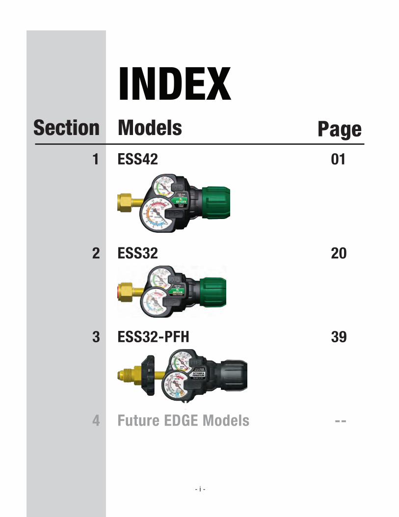
INDEXSection Models Page
1 ESS42
- i -
01
2 ESS32 20
4 Future EDGE Models --
3 ESS32-PFH 39
Deliv
ery
Pres
sure
(PSI
G)
Flow (SCFH)1000 2000 3000
15
40
60
80
100
120
140150
4000 5000 6000 700000
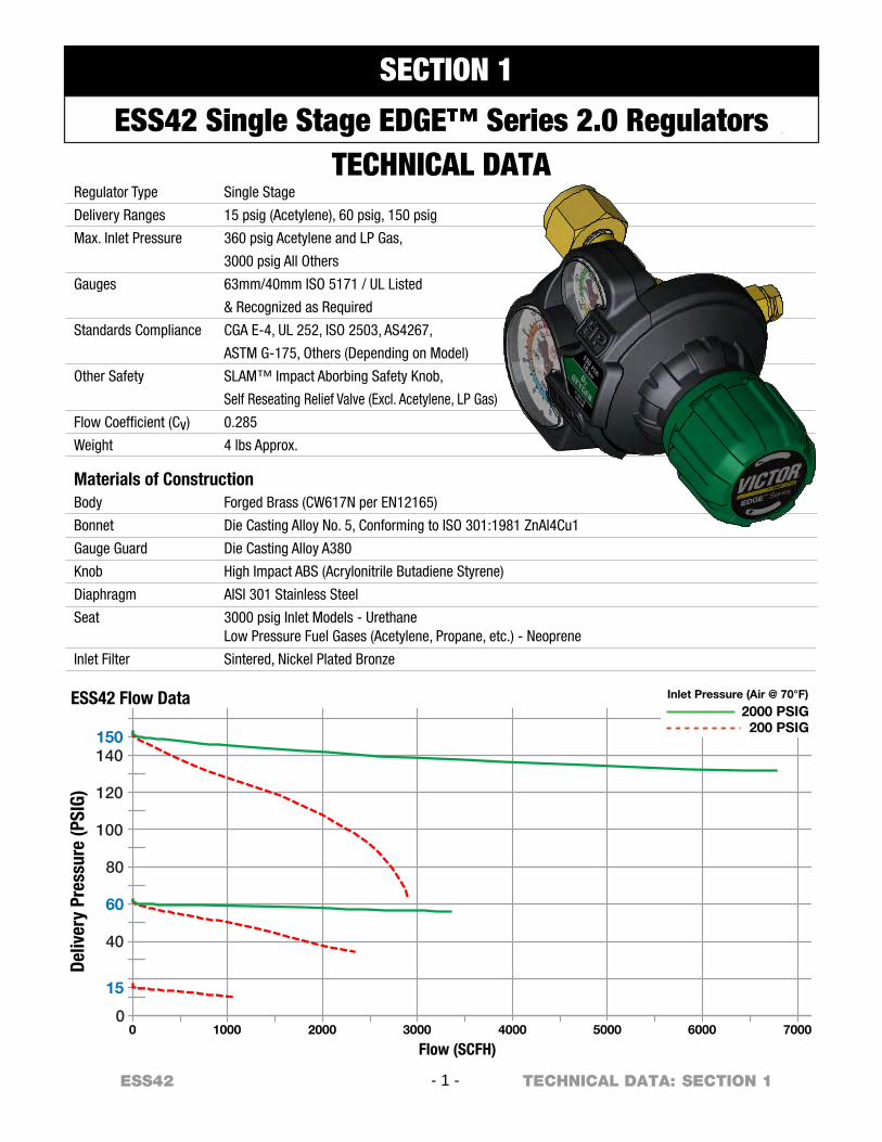
ESS42 Flow Data Inlet Pressure (Air @ 70°F)
2000 PSIG200 PSIG
Regulator Type
Delivery Ranges
Max. Inlet Pressure
Gauges
Standards Compliance
Other Safety
Flow Coefficient (Cv)
Weight
Single Stage
15 psig (Acetylene), 60 psig, 150 psig
360 psig Acetylene and LP Gas,
3000 psig All Others
63mm/40mm ISO 5171 / UL Listed
& Recognized as Required
CGA E-4, UL 252, ISO 2503, AS4267,
ASTM G-175, Others (Depending on Model)
SLAM™ Impact Aborbing Safety Knob,
Self Reseating Relief Valve (Excl. Acetylene, LP Gas)
0.285
4 lbs Approx.
Materials of ConstructionBody
Bonnet
Gauge Guard
Knob
Diaphragm
Seat
Inlet Filter
Forged Brass (CW617N per EN12165)
Die Casting Alloy No. 5, Conforming to ISO 301:1981 ZnAl4Cu1
Die Casting Alloy A380
High Impact ABS (Acrylonitrile Butadiene Styrene)
AISI 301 Stainless Steel
3000 psig Inlet Models - UrethaneLow Pressure Fuel Gases (Acetylene, Propane, etc.) - Neoprene
Sintered, Nickel Plated Bronze
- 1 -ESS42 SECTION 1TECHNICAL DATA:
SECTION 1
ESS42 Single Stage EDGE™ Series 2.0 RegulatorsTECHNICAL DATA

ESS42 - 2 - SECTION 1 GENERAL:
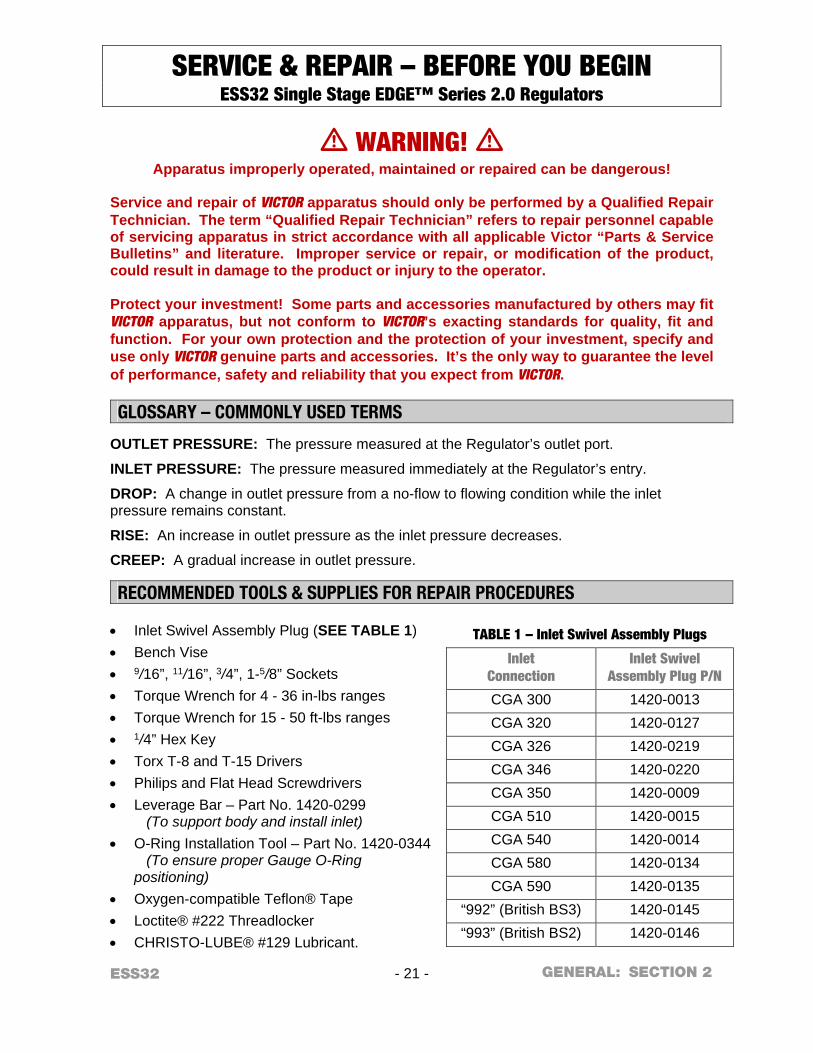
SERVICE & REPAIR – BEFORE YOU BEGIN ESS42 Single Stage EDGE™ Series 2.0 Regulators
m WARNING! m Apparatus improperly operated, maintained or repaired can be dangerous!
Service and repair of VICTOR apparatus should only be performed by a Qualified Repair Technician. The term “Qualified Repair Technician” refers to repair personnel capable of servicing apparatus in strict accordance with all applicable Victor “Parts & Service Bulletins” and literature. Improper service or repair, or modification of the product, could result in damage to the product or injury to the operator. Protect your investment! Some parts and accessories manufactured by others may fit VICTOR apparatus, but not conform to VICTOR’s exacting standards for quality, fit and function. For your own protection and the protection of your investment, specify and use only VICTOR genuine parts and accessories. It’s the only way to guarantee the level of performance, safety and reliability that you expect from VICTOR.
GLOSSARY – COMMONLY USED TERMS
OUTLET PRESSURE: The pressure measured at the Regulator’s outlet port.
INLET PRESSURE: The pressure measured immediately at the Regulator’s entry.
DROP: A change in outlet pressure from a no-flow to flowing condition while the inlet pressure remains constant.
RISE: An increase in outlet pressure as the inlet pressure decreases.
CREEP: A gradual increase in outlet pressure. RECOMMENDED TOOLS & SUPPLIES FOR REPAIR PROCEDURES
Inlet Swivel Assembly Plug (SEE TABLE 1) Bench Vise 9/16”, 11/16”, 3/4”, 1-5/8” Sockets Torque Wrench for 4 - 36 in-lbs ranges Torque Wrench for 15 - 50 ft-lbs ranges 1/4” Hex Key Torx T-8 and T-15 Drivers Philips and Flat Head Screwdrivers Leverage Bar – Part No. 1420-0299
(To support body and install inlet)
O-Ring Installation Tool – Part No. 1420-0344 (To ensure proper Gauge O-Ring positioning)
Oxygen-compatible Teflon® Tape Loctite® #222 Threadlocker CHRISTO-LUBE® #129 Lubricant.
TABLE 1 – Inlet Swivel Assembly Plugs
Inlet Connection
Inlet Swivel Assembly Plug P/N
CGA 300 1420-0013 CGA 320 1420-0127 CGA 326 1420-0219 CGA 346 1420-0220 CGA 350 1420-0009 CGA 510 1420-0015 CGA 540 1420-0014 CGA 580 1420-0134 CGA 590 1420-0135
“992” (British BS3) 1420-0145 “993” (British BS2) 1420-0146
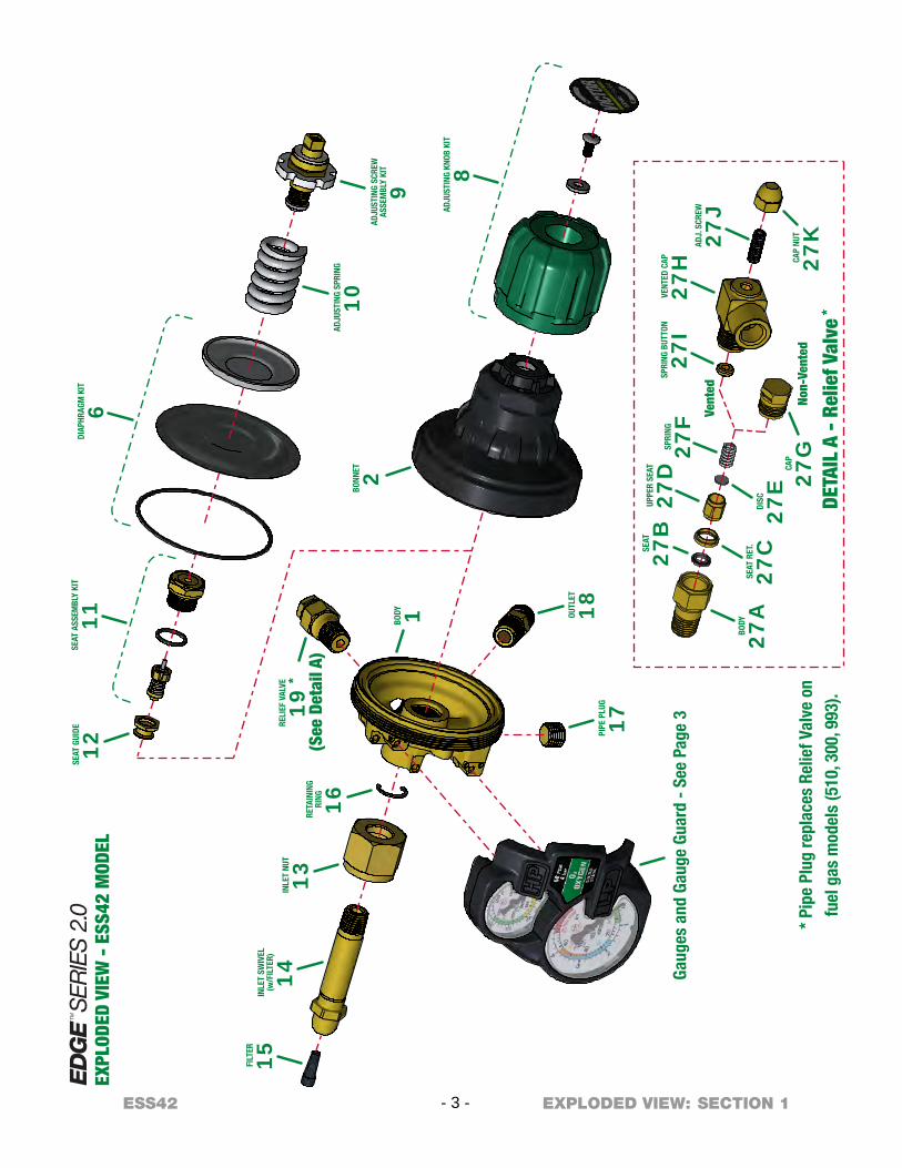
SEAT
ASS
EMBL
Y KI
T
11 BODY 1
RELI
EF V
ALVE
19
*
(See
Det
ail A
)
EXPL
ODED
VIE
W -
ESS
42 M
ODEL
BONN
ET 2
Gaug
es a
nd G
auge
Gua
rd -
See
Pag
e 3
DIAP
HRAG
M K
IT
6
RETA
ININ
GRI
NG 16
INLE
T NU
T
13
INLE
T SW
IVEL
(w/F
ILTE
R)
14
FILT
ER
15
PIPE
PLU
G
17
OUTL
ET
18
SEAT
GUI
DE
12
ADJU
STIN
G SP
RING
10AD
JUST
ING
SCRE
WAS
SEM
BLY
KIT
9
ADJU
STIN
G KN
OB K
IT
8
BODY
27A
SEAT
RET
.
27C
DISC
27E
SEAT
27B
UPPE
R SE
AT
27D
SPRI
NG
27F
CAP
27G
DETA
IL A
- R
elie
f Val
ve *
* Pi
pe P
lug
repl
aces
Rel
ief V
alve
on
fu
el g
as m
odel
s (5
10, 3
00, 9
93).
SPRI
NG B
UTTO
N
27I
VENT
ED C
AP
27H
ADJ.
SCR
EW
27J
CAP
NUT
27K
Vent
ed
Non-
Vent
ed
- 3 -ESS42 SECTION 1EXPLODED VIEW:
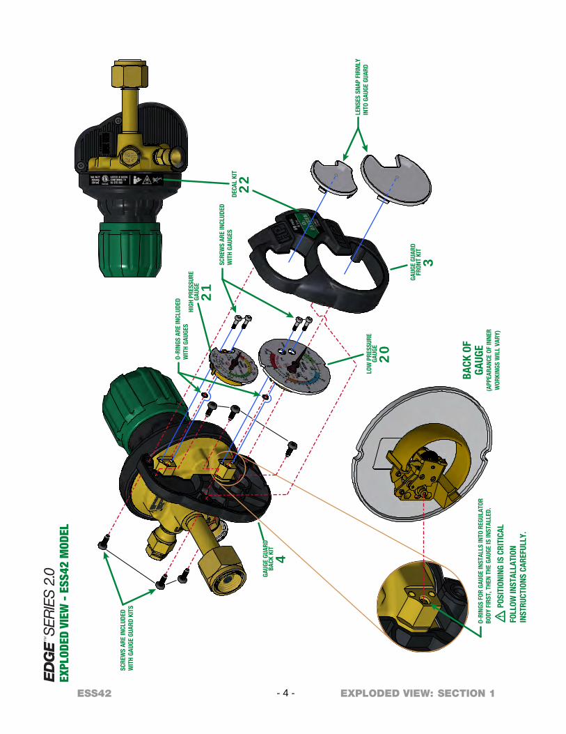
BACK
OF
GAUG
E(A
PPEA
RANC
E OF
INNE
RW
ORKI
NGS
WIL
L VA
RY)
m P
OSIT
IONI
NG IS
CRI
TICA
L
FOLL
OW IN
STAL
LATI
ONIN
STRU
CTIO
NS C
AREF
ULLY
.
LENS
ES S
NAP
FIRM
LYIN
TO G
AUGE
GUA
RD
SCRE
WS
ARE
INCL
UDED
WIT
H GA
UGES
O-RI
NGS
ARE
INCL
UDED
WIT
H GA
UGES
DECA
L KI
T
22
HIGH
PRE
SSUR
EGA
UGE
21
LOW
PRE
SSUR
EGA
UGE
20
GAUG
E GU
ARD
FRON
T KI
T
3
SCRE
WS
ARE
INCL
UDED
WIT
H GA
UGE
GUAR
D KI
TS
GAUG
E GU
ARD
BACK
KIT
4
O-RI
NGS
FOR
GAUG
E IN
STAL
LS IN
TO R
EGUL
ATOR
BODY
FIR
ST, T
HEN
THE
GAUG
E IS
INST
ALLE
D.
EXPL
ODED
VIE
W -
ESS
42 M
ODEL
- 4 -ESS42 SECTION 1EXPLODED VIEW:
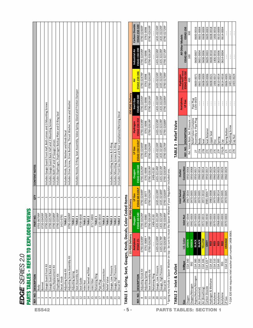
REF.
NO
.TRAP
NOITPIRCSED
NO
.Q
TYCO
NTE
NT
NO
TES
1Bo
dy07
01-0
675R
P1
2Bo
nnet
0720
-034
5RP
13
Gaug
e Gu
ard
Fron
t Kit
0790
-025
6RP
1In
clud
es G
auge
Gua
rd F
ront
Hal
f, Bo
th L
ense
s and
3 M
ounti
ng S
crew
s4
Gaug
e Gu
ard
Back
Kit
0790
-025
7RP
1In
clud
es G
auge
Gua
rd B
ack
Half
and
3 Mou
nting
Scr
ews
5Le
ns R
epla
cem
ent K
it07
90-0
258R
P1
Incl
udes
Bot
h HP
and
LP
Gaug
e Le
nses
6Di
aphr
agm
Kit
0790
-025
9RP
1In
clud
es D
iaph
ragm
, Dia
phra
gm B
acku
p Pl
ate
and
O-R
ing
Seal
7De
cal,
5141bonK
-079
11
8Ad
justing
Kno
b Ki
tTA
BLE
11
Incl
udes
Kno
b, S
crew
, Was
her a
nd K
nob
Deca
l9
Adjusting
Scr
ew A
ssem
bly
Kit
0790
-026
0RP
1In
clud
es D
rive
Scre
w, D
rive
Bush
ing,
Thr
ust W
ashe
r, Sc
rew
and
Was
her
10Ad
justing
Spr
ing
TABL
E 1
111
Seat
Ass
embl
y Ki
t TA
BLE
11
Incl
udes
Noz
zle, O
-Rin
g, S
eat A
ssem
bly,
Val
ve S
prin
g, G
land
and
Fric
tion
Dam
per
12Se
at
8070ediuG
-001
81
13In
let N
utTA
BLE
21
14In
let S
wiv
el w
/Filt
erTA
BLE
21
15In
let
7170retliF
-000
31
16Re
tain
ing
Ring
TABL
E 1
117
Pipe
5011
gulP-0
014
118
Out
let C
onne
ction
TABL
E 2
119
Relie
f Val
veTA
BLE
31
20Ga
uge,
Low
Pre
ssur
eTA
BLE
11
Incl
udes
Mou
nting
Scr
ews &
O-R
ing
21Ga
uge,
Hig
h Pr
essu
reTA
BLE
11
Incl
udes
Mou
nting
Scr
ews &
O-R
ing
22De
cal K
itTA
BLE
11
Incl
udes
Fro
nt G
as D
ecal
and
Rea
r Com
plia
nce/
War
ning
Dec
al
TABL
E 1
- Spr
ing,
Sea
t, G
auge
s, K
nob,
Dec
als,
Col
or C
oded
Item
s15
PSI
G D
eliv
ery
Acet
ylen
eO
xyge
nLP
Gas
Oxy
gen
LP G
asHy
drog
enIn
ert G
asAi
rIn
dust
rial A
irCa
rbon
Dio
xide
REF.
NO
.DE
SCRI
PTIO
NES
S42-
15-
ESS4
2-60
-540
ESS4
2-60
-510
LPES
S42-
150-
540
ESS4
2-15
0-51
0LP
ESS4
2-15
0-35
0ES
S42-
150-
580
ESS4
2-15
0-34
6ES
S42-
150-
590
ESS4
2-15
0-32
08
Adjusting
Kno
b Ki
t07
90-0
243R
P07
90-0
242R
P07
90-0
244R
P07
90-0
242R
P07
90-0
244R
P07
90-0
243R
P07
90-0
245R
P07
90-0
247R
P07
90-0
245R
P07
90-0
246R
P10
Adjusting
Spr
ing
0761
-008
907
61-0
080
0761
-007
707
61-0
098
0761
-009
807
61-0
098
0761
-009
807
61-0
098
0761
-009
807
61-0
098
11Se
at A
ssem
bly
Kit
0790
-026
2RP
0790
-026
1RP
0790
-026
2RP
0790
-026
1RP
0790
-026
2RP
0790
-026
1RP
0790
-026
1RP
0790
-026
1RP
0790
-026
1RP
0790
-026
1RP
16Re
tain
ing
Ring
- - -
1406
-013
0- -
-14
06-0
130
- - -
- - -
- - -
- - -
- - -
- - -
20Ga
uge,
Low
Pre
ssur
e
*
1435
-021
0RP
1435
-021
2RP
1435
-021
3RP
1435
-021
4RP
1435
-021
5RP
1435
-021
5RP
1435
-021
5RP
1435
-021
5RP
1435
-021
5RP
1435
-021
5RP
21Ga
uge,
Hig
h Pr
essu
re14
35-0
217R
P14
35-0
221R
P14
35-0
218R
P14
35-0
221R
P14
35-0
218R
P14
35-0
222R
P14
35-0
222R
P14
35-0
222R
P14
35-0
222R
P14
35-0
222R
P22
Deca
l Kit
0790
-026
3RP
0790
-026
4RP
0790
-026
6RP
0790
-026
5RP
0790
-026
7RP
0790
-026
8RP
0790
-026
9RP
0790
-027
0RP
0790
-027
1RP
0790
-027
2RP
* Sp
ring
may
incl
ude
a Sp
acer
Was
her o
n to
p - b
e su
re to
reus
e th
e Sp
acer
Was
her i
f you
r Reg
ulat
or in
clud
ed o
ne.
TABL
E 2
- Inl
et &
Out
let
Inle
t Sw
ivel
Out
let
Inle
t Type
I.D. C
olor
Inle
t Nut
(w/F
ilter
)Co
nnectio
nCG
A 54
0G
REEN
0967
-004
409
67-0
034
0950
-006
899
2G
REEN
0992
-000
309
70-0
005
0950
-006
8CG
A 58
0BL
ACK
0973
-000
309
70-0
005
0950
-001
7CG
A 59
0BL
ACK
0974
-000
309
70-0
005
0960
-001
4CG
A 34
6YE
LLO
W09
72-0
015
0972
-001
009
60-0
014
CGA
320
*G
REY
0985
-003
009
85-0
004
*09
50-0
017
CGA
350
RED
0983
-000
309
83-0
008
0960
-002
9CG
A 51
0RE
D09
70-0
003
0970
-000
509
60-0
029
CGA
300
RED
0968
-000
309
68-0
014
0960
-002
999
3RE
D09
93-0
003
0970
-000
509
60-0
029
CGA
510
ORA
NG
E09
70-0
003
0970
-000
509
60-0
029
* CG
A 32
0 in
let r
equi
res i
nlet
was
her p
art n
umbe
r 140
8-00
65.
TABL
E 3
- Rel
ief V
alve
Acet
ylen
e,LP
Gas
Hydr
ogen
(V
ente
d Re
lief V
alve
)
REF.
NO
.DE
SCRI
PTIO
NES
S42-
150-
350
ESS4
2-60
-ES
S42-
150
Rel.
Valv
e N
om. S
et P
ress
ure
-->- -
-40
010
030
0
27A
Body
- - -
0601
-000
606
01-0
004
0601
-000
427
BSe
at- -
-06
08-0
009
0608
-000
606
08-0
009
27C
Seat
Ret
aine
r- -
-06
09-0
006
0609
-000
306
09-0
003
27D
Upp
er S
eat
- - -
0608
-002
106
08-0
018
0608
-001
827
EDi
sc- -
-14
06-0
017
1406
-001
614
06-0
016
27F
Sprin
g- -
-06
10-0
014
0610
-000
606
10-0
009
27G/
H- -
-06
14-0
004
0614
-000
4Ca
p - -
-06
14-0
016
- - -
- - -
27I
Sprin
g Button
- - -
0606
-000
5- -
-- -
-27
JAd
justing
Scre
w- -
-14
01-0
007
- - -
- - -
27K
Cap
Nut
1403
-002
4
0600
-001
6
All O
ther
Mod
els
Relie
f Valv
e Com
plet
e As
sem
bly
or P
ipe
Plug
27Pi
pe Pl
ug11
05-0
014
0600
-007
106
00-0
007
Argo
n/He
lium
/Nitr
ogen
LP G
as
150
PSIG
Del
iver
y60
PSI
G D
eliv
ery
Gas
Oxy
gen
Oxy
gen/
Nitr
ogen
Air (
Indu
stria
l)Ai
r (Br
eath
ing)
Carb
on D
ioxi
deHy
drog
en &
Met
hane
Acet
ylen
eAc
etyl
ene
Acet
ylen
e
PART
S TA
BLES
- R
EFER
TO
EXPL
ODED
VIE
WS
- 5 -ESS42 SECTION 1PARTS TABLES:
ESS42 - 6 - SECTION 1
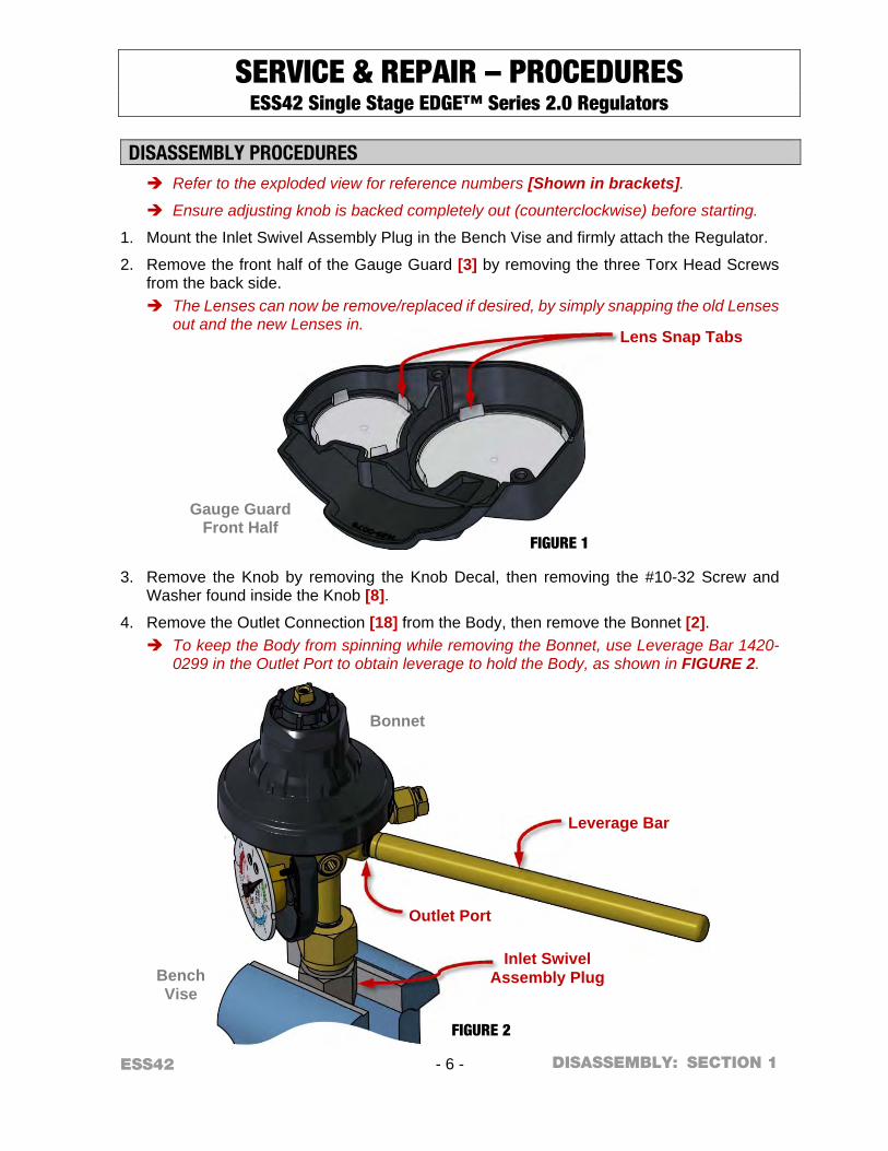
SERVICE & REPAIR – PROCEDURES ESS42 Single Stage EDGE™ Series 2.0 Regulators
DISASSEMBLY PROCEDURES Refer to the exploded view for reference numbers [Shown in brackets].
Ensure adjusting knob is backed completely out (counterclockwise) before starting.
1. Mount the Inlet Swivel Assembly Plug in the Bench Vise and firmly attach the Regulator.
2. Remove the front half of the Gauge Guard [3] by removing the three Torx Head Screws from the back side. The Lenses can now be remove/replaced if desired, by simply snapping the old Lenses
out and the new Lenses in.
3. Remove the Knob by removing the Knob Decal, then removing the #10-32 Screw and Washer found inside the Knob [8].
4. Remove the Outlet Connection [18] from the Body, then remove the Bonnet [2]. To keep the Body from spinning while removing the Bonnet, use Leverage Bar 1420-
0299 in the Outlet Port to obtain leverage to hold the Body, as shown in FIGURE 2.
Bench Vise
Bonnet
FIGURE 2
Gauge Guard Front Half
FIGURE 1
DISASSEMBLY:
Lens Snap Tabs
Leverage Bar
Inlet Swivel Assembly Plug
Outlet Port
ESS42 - 7 - SECTION 1
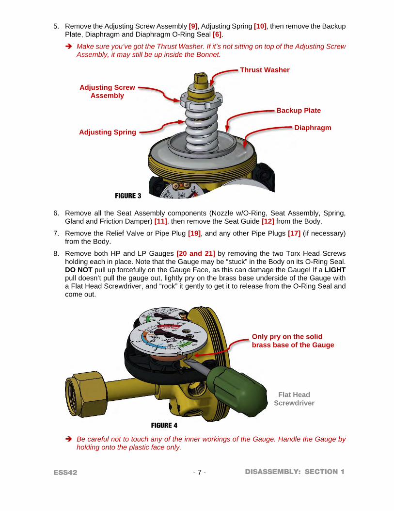
5. Remove the Adjusting Screw Assembly [9], Adjusting Spring [10], then remove the Backup Plate, Diaphragm and Diaphragm O-Ring Seal [6].
Make sure you’ve got the Thrust Washer. If it’s not sitting on top of the Adjusting Screw Assembly, it may still be up inside the Bonnet.
6. Remove all the Seat Assembly components (Nozzle w/O-Ring, Seat Assembly, Spring, Gland and Friction Damper) [11], then remove the Seat Guide [12] from the Body.
7. Remove the Relief Valve or Pipe Plug [19], and any other Pipe Plugs [17] (if necessary) from the Body.
8. Remove both HP and LP Gauges [20 and 21] by removing the two Torx Head Screws holding each in place. Note that the Gauge may be “stuck” in the Body on its O-Ring Seal. DO NOT pull up forcefully on the Gauge Face, as this can damage the Gauge! If a LIGHT pull doesn’t pull the gauge out, lightly pry on the brass base underside of the Gauge with a Flat Head Screwdriver, and “rock” it gently to get it to release from the O-Ring Seal and come out.
Be careful not to touch any of the inner workings of the Gauge. Handle the Gauge by holding onto the plastic face only.
Flat Head Screwdriver
FIGURE 4
FIGURE 3
DISASSEMBLY:
Diaphragm
Backup Plate
Adjusting Screw Assembly
Adjusting Spring
Thrust Washer
Only pry on the solid brass base of the Gauge

ESS42 - 8 - SECTION 1
9. Carefully remove the Gauge O-Rings, taking care not to scratch any sealing surfaces.
There is one O-Ring per Gauge. Typically they will remain in the body after Gauge removal, but if not there, they may also still be on the Pressure Port of the Gauge itself.
10. It is not required to remove the back half of the Gauge Guard [4] for any repairs that may be needed, but if removal is desired, simply remove the three Torx Head Screws holding it in place.
11. Install Leverage Bar 1420-0299 into any ¼ NPT port in the Body (if not already there), and use the bar to unscrew the Body off the Inlet Swivel [14].
Watch the Inlet Swivel while trying to turn the Body. If the Swivel is turning with the Body, then you need to tighten the Inlet Nut tighter on the Inlet Swivel Assembly Plug.
12. If necessary, disassemble the Relief Valve as shown in DETAIL A.
m CAUTION! You should never reuse the Nozzle O-Ring, Seat Assembly, Friction Damper, Inlet Filter or Diaphragm O-Ring Seal. Replace them with new parts each time you assemble a Regulator.
CLEANING PARTS It is recommended to clean all metal parts for oxygen service, regardless of Regulator Model being repaired. There are several ways to clean components for oxygen service; the following standards are recommended reading for more detailed information on methods and processes:
CGA G-4.1 “Cleaning Equipment for Oxygen Service”
ASTM G-93 “Standard Practice for Cleaning Methods and Cleanliness Levels for Material and Equipment Used in Oxygen-Enriched Environments”
ASTM G-127 “Standard Guide for the Selection of Cleaning Agents for Oxygen Systems”
Gauge
FIGURE 5
Regulator Body
Gauge Guard Back Half
DISASSEMBLY:
Pressure Ports
Pressure Port
Mounting Screws for Gauge Guard Back Half

ESS42 - 9 - SECTION 1
For metal parts, VICTOR suggests using CCI Envirospray Liquid, used per the manufacturer's instructions, followed by a hot water rinse and thorough drying. Additional information can be found at http://www.ccichemical.com.
DO NOT allow non-metal parts to come in contact with cleaning solvents. Cleaning solvents can cause non-metal parts to swell and/or crack. To clean these parts, use a non-petroleum based mild soap solution, followed by a thorough rinsing in water. Dry parts completely prior to reassembling.
ASSEMBLY PROCEDURES Refer to the exploded view for reference numbers [Shown in brackets]
m IMPORTANT NOTES ABOUT SEALING PIPE THREADS: When using Teflon® tape where noted: Apply two to three layers around the
threads, leaving the first thread clean. Insure your Teflon® tape is oxygen-compatible.
When using Loctite® #222 Threadlocker where noted: Apply two to three drops to the second and third thread, leaving the first thread clean.
1. Install a new Filter [15] into the Inlet Swivel (or replace entire Inlet Swivel w/Filter installed [14]), and apply Teflon® tape to the Inlet Swivel threads.
2. If not already in place, mount the Inlet Swivel Assembly Plug back in the Bench Vise. Firmly attach the Inlet Swivel and Inlet Nut [13] onto the Inlet Swivel Assembly Plug. Install Retaining Ring [16], if equipped.
3. Screw the Body onto the Inlet Swivel, screw the Leverage Bar 1420-0299 into the outlet port of the Body (light hand tight), and then use the Leverage Bar to tighten the Body onto the Inlet Connection. At this point, tighten enough so that the body cannot be turned by hand without the assistance of the Leverage Bar. Final torque for the Inlet Connection will occur in upcoming STEP 15.
Bench Vise
Regulator Body
FIGURE 6
ASSEMBLY:
Leverage Bar
Inlet Swivel Assembly Plug

ESS42 - 10 - SECTION 1
4. Preassemble the Relief Valve (if so equipped): Assemble (or reassemble) the Relief Valve [19] as shown in DETAIL A. Use no lubricants or sealants. If your Regulator model has a Pipe Plug instead of a Relief Valve, or if your Relief Valve is already assembled and tested, you can skip to STEP 8.
5. To ensure proper Relief Valve performance, perform the following test procedures before assembling the Relief Valve in the Regulator.
a. Attach the Relief Valve to a 450 PSIG source of oil-free air or dry nitrogen.
b. Slowly pressurize the Relief Valve, increasing to the recommended blow-off pressure listed in TABLE 2 below. Note that VICTOR Relief Valves are stamped with their nominal set pressure, in case you’re unsure which Relief Valve you have.
Non-Vented Relief Valves:
If the Relief Valve vents before the minimum blow-off pressure is reached, then a second Disc [27E] may be added. If it still vents, then the Spring [27F] must be replaced.
Vented Relief Valves:
If the Vented Relief Valve fails to vent within the recommended blow-off pressure, reset the Adjusting Screw [27J] as necessary and perform this step again. Make sure you fully bleed off all pressure each time you test for blow-off pressure.
TABLE 2 – Relief Valve Blow-off Pressure Relief Valve
Nominal Set Point Recommended
Blow-off Pressure
60 PSIG 55 to 66 PSIG
100 PSIG 90 to 110 PSIG
200 PSIG 180 to 220 PSIG
300 PSIG 270 to 330 PSIG
400 PSIG 360 to 440 PSIG
6. When all testing is completed, bleed pressure off the Relief Valve. Install the Cap Nut [27K] on the Vented Relief Valve.
7. Apply Teflon® tape to the Relief Valve [19] threads. Install the Relief Valve (or Pipe Plug) into the Body and torque to 15 ft-lbs MIN.
8. Apply Teflon® tape to any other Pipe Plug [17] threads. Install Pipe Plugs into the Body where appropriate, and torque to 15 ft-lbs MIN.
The Outlet Connection gets installed after STEP 18.
9. At this point, thoroughly blow out the Body assembly with pressurized oil-free air or dry nitrogen to insure it is completely free of chips and debris.
10. If the back half of the Gauge Guard was removed, reinstall it now using three Torx head screws. Torque Screws to 16 - 20 in-lbs.
ASSEMBLY:
ESS42 - 11 - SECTION 1
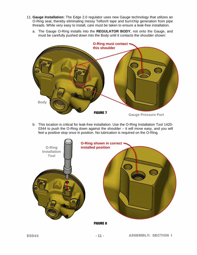
11. Gauge Installation: The Edge 2.0 regulator uses new Gauge technology that utilizes an
O-Ring seal, thereby eliminating messy Teflon® tape and burr/chip generation from pipe threads. While very easy to install, care must be taken to ensure a leak-free installation.
a. The Gauge O-Ring installs into the REGULATOR BODY, not onto the Gauge, and must be carefully pushed down into the Body until it contacts the shoulder shown:
b. This location is critical for leak-free installation. Use the O-Ring Installation Tool 1420-0344 to push the O-Ring down against the shoulder – it will move easy, and you will feel a positive stop once in position. No lubrication is required on the O-Ring.
Gauge Pressure Port
Body
O-Ring Installation
Tool
FIGURE 7
FIGURE 8
ASSEMBLY:
O-Ring must contact this shoulder
O-Ring shown in correct installed position
ESS42 - 12 - SECTION 1
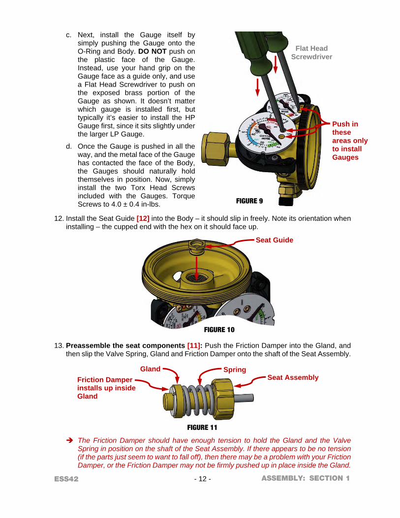
c. Next, install the Gauge itself by
simply pushing the Gauge onto the O-Ring and Body. DO NOT push on the plastic face of the Gauge. Instead, use your hand grip on the Gauge face as a guide only, and use a Flat Head Screwdriver to push on the exposed brass portion of the Gauge as shown. It doesn’t matter which gauge is installed first, but typically it’s easier to install the HP Gauge first, since it sits slightly under the larger LP Gauge.
d. Once the Gauge is pushed in all the way, and the metal face of the Gauge has contacted the face of the Body, the Gauges should naturally hold themselves in position. Now, simply install the two Torx Head Screws included with the Gauges. Torque Screws to 4.0 ± 0.4 in-lbs.
12. Install the Seat Guide [12] into the Body – it should slip in freely. Note its orientation when installing – the cupped end with the hex on it should face up.
13. Preassemble the seat components [11]: Push the Friction Damper into the Gland, and then slip the Valve Spring, Gland and Friction Damper onto the shaft of the Seat Assembly.
The Friction Damper should have enough tension to hold the Gland and the Valve Spring in position on the shaft of the Seat Assembly. If there appears to be no tension (if the parts just seem to want to fall off), then there may be a problem with your Friction Damper, or the Friction Damper may not be firmly pushed up in place inside the Gland.
Flat Head Screwdriver
FIGURE 9
FIGURE 10
FIGURE 11
ASSEMBLY:
Push in these areas only to install Gauges
Seat Guide
Friction Damper installs up inside Gland
Gland Spring Seat Assembly

ESS42 - 13 - SECTION 1
14. Install the preassembled seat components into the Regulator Body – with the Friction
Damper and Gland fitting down into the cup shape of the Seat Guide. 15. Apply a light coat of CHRISTO-LUBE® #129 Lubricant to the Nozzle O-Ring, and install
the new O-Ring onto the Nozzle, taking care to guide it carefully over the Nozzle threads to avoid nicks or tears. Install the Nozzle into the Regulator Body and torque to 15 - 20 ft-lbs. Note that 15 - 20 ft-lbs is the same recommended torque for the Inlet Connection Swivel, so as you torque down the Nozzle, you’re also finish-tightening the Inlet Swivel to the correct torque value. Watch the Inlet Swivel while you torque down the Nozzle. If the Swivel is turning with
the Body, then you need to tighten the Inlet Nut tighter on the Inlet Swivel Assembly Plug. You want to be sure that the 15 - 20 ft-lbs torque is being applied to both the Nozzle threads and the Inlet Swivel threads.
16. Apply a light coat of CHRISTO-LUBE® #129 Lubricant to the Diaphragm O-Ring Seal [6], then install the O-Ring into the groove in the top of the Body.
17. Install the Diaphragm onto the Regulator Body, ensuring it is centered within the small lip on the top of the Body. Then install the Backup Plate, Adjusting Spring [10], and Adjusting Screw Assembly [9]. Don’t forget the Thrust Washer! It should be sitting on top of the Adjusting Screw Assembly. Regulator function will be impaired without it.
FIGURE 12
FIGURE 13 ASSEMBLY:
O-Ring in groove
Thrust Washer
Diaphragm
Backup Plate
Adjusting Screw Assembly
Adjusting Spring
ESS42 - 14 - SECTION 1
18. Install the Bonnet [2] onto the Body. Take care while slipping the Bonnet down over the
internal components – the ribs inside the Bonnet must slide into the scallops of the Guide Bushing. Torque the Bonnet to 45 - 50 ft-lbs. Use the Leverage Bar 1420-0299 in the open Outlet Port to prevent the assembly from
rotating while torqueing the Bonnet.
19. Apply only Loctite® #222 threadlocker to the Outlet Connection [18] threads. Install the Outlet Connection into the Body and torque to 15 ft-lbs MIN.
20. Apply a small amount of CHRISTO-LUBE® #129 to the top surface of the Bonnet (the surface around the square of the Drive Screw), then slip the Knob [8] into position – the square hole inside the knob mates to the square shaft of the Drive Screw.
21. Install the #10-32 Screw and Washer to hold the Knob on. Torque this Screw to 30 - 36 in-lbs. Then apply the new Knob Decal.
22. Snap new Lenses into the front half of the Gauge Guard [3] (unless already installed), and install the front half of the Gauge Guard onto the regulator using three Torx Head Screws from the back side. Torque Screws to 16 - 20 in-lbs.
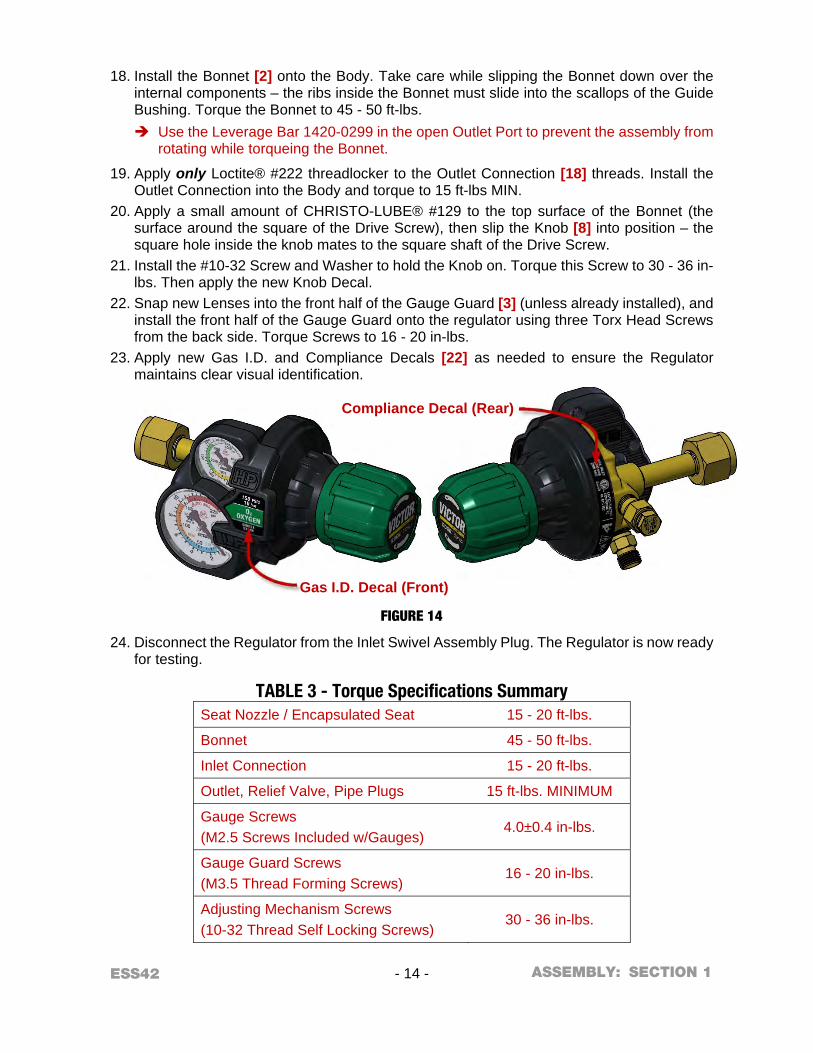
23. Apply new Gas I.D. and Compliance Decals [22] as needed to ensure the Regulator maintains clear visual identification.
24. Disconnect the Regulator from the Inlet Swivel Assembly Plug. The Regulator is now ready for testing.
TABLE 3 - Torque Specifications Summary Seat Nozzle / Encapsulated Seat 15 - 20 ft-lbs.
Bonnet 45 - 50 ft-lbs.
Inlet Connection 15 - 20 ft-lbs.
Outlet, Relief Valve, Pipe Plugs 15 ft-lbs. MINIMUM
Gauge Screws (M2.5 Screws Included w/Gauges)
4.0±0.4 in-lbs.
Gauge Guard Screws (M3.5 Thread Forming Screws)
16 - 20 in-lbs.
Adjusting Mechanism Screws (10-32 Thread Self Locking Screws)
30 - 36 in-lbs.
FIGURE 14
ASSEMBLY:
Gas I.D. Decal (Front)
Compliance Decal (Rear)
ESS42 - 15 - SECTION 1
RECOMMENDED TOOLS AND SUPPLIES FOR TEST PROCEDURES Test Gun (quick opening on/off valve) with #52 (.0635”) restricting orifice Valved source of oil-free air or dry nitrogen TEST PROCEDURES
m WARNING! m For your safety, and the safety of others:
Always test with oil-free air or dry nitrogen only. Always wear eye protection while testing a Regulator. Always perform all of the following test procedures after reassembling a Regulator.
1. Set gas supply to the proper pressure shown in the following table:
TABLE 4 – Edge 2.0 Regulator Test Pressures Gas Service Manifold Pressure for Testing
Acetylene & LP Gas 250±20 PSIG CO2 & N2O 1000±100 PSIG Air, Argon, Hydrogen, Helium, Nitrogen, Oxygen 2000±100 PSIG
2. Attach the Regulator to the gas supply – start the Inlet Nut by hand (do not force), and tighten securely with a wrench to create a seal.
3. Contamination purge prior to test: a. Turn the Regulator Adjusting Knob clockwise two or three times until you feel slight
tension being applied to the Adjusting Spring. b. Slowly open and close the Gas Supply Valve two or three times to remove
contamination that may cause malfunctions. Leave the Gas Supply Valve closed. c. If no flow comes through the Regulator, determine the cause – refer to the
TROUBLESHOOTING CHART at the end of this section.
4. Turn the Adjusting Knob counterclockwise until it stops, and attach the Test Gun (with a #52 restricting orifice) to the outlet of the Regulator.
5. Open the Gas Supply Valve and close the Test Gun. a. Working pressure will appear on the High Pressure Gauge. b. If the Low Pressure Gauge begins to show pressure building, turn the Gas Supply Valve
off and refer to the TROUBLESHOOTING CHART.
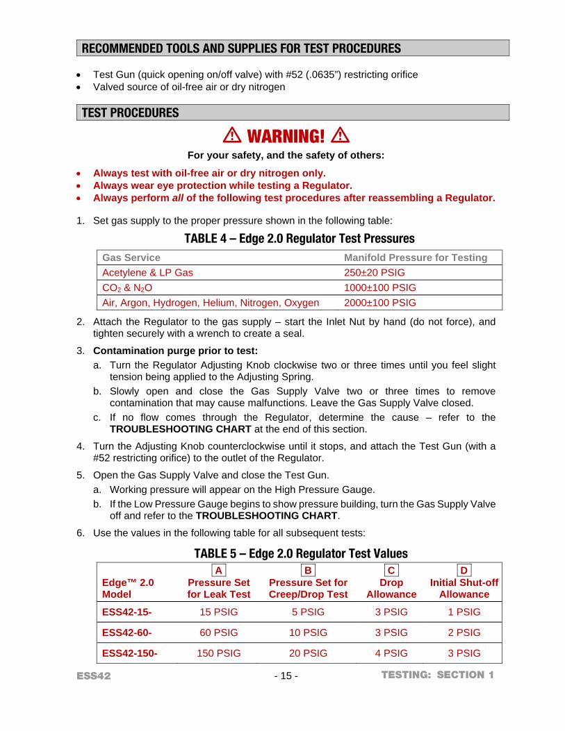
6. Use the values in the following table for all subsequent tests:
TABLE 5 – Edge 2.0 Regulator Test Values
Edge™ 2.0 Model
A Pressure Set for Leak Test
B Pressure Set for Creep/Drop Test
C Drop
Allowance
D Initial Shut-off
Allowance
ESS42-15- 15 PSIG 5 PSIG 3 PSIG 1 PSIG
ESS42-60- 60 PSIG 10 PSIG 3 PSIG 2 PSIG
ESS42-150- 150 PSIG 20 PSIG 4 PSIG 3 PSIG
TESTING:
ESS42 - 16 - SECTION 1
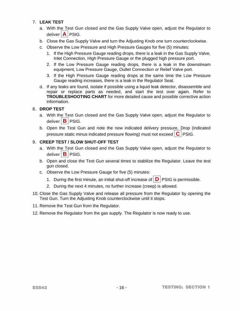
7. LEAK TEST
a. With the Test Gun closed and the Gas Supply Valve open, adjust the Regulator to deliver A PSIG.
b. Close the Gas Supply Valve and turn the Adjusting Knob one turn counterclockwise. c. Observe the Low Pressure and High Pressure Gauges for five (5) minutes:
1. If the High Pressure Gauge reading drops, there is a leak in the Gas Supply Valve, Inlet Connection, High Pressure Gauge or the plugged high pressure port.
2. If the Low Pressure Gauge reading drops, there is a leak in the downstream equipment, Low Pressure Gauge, Outlet Connection or Relief Valve port.
3. If the High Pressure Gauge reading drops at the same time the Low Pressure Gauge reading increases, there is a leak in the Regulator Seat.
d. If any leaks are found, isolate if possible using a liquid leak detector, disassemble and repair or replace parts as needed, and start the test over again. Refer to TROUBLESHOOTING CHART for more detailed cause and possible corrective action information.
8. DROP TEST a. With the Test Gun closed and the Gas Supply Valve open, adjust the Regulator to
deliver B PSIG. b. Open the Test Gun and note the new indicated delivery pressure. Drop (indicated
pressure static minus indicated pressure flowing) must not exceed C PSIG.
9. CREEP TEST / SLOW SHUT-OFF TEST a. With the Test Gun closed and the Gas Supply Valve open, adjust the Regulator to
deliver B PSIG. b. Open and close the Test Gun several times to stabilize the Regulator. Leave the test
gun closed. c. Observe the Low Pressure Gauge for five (5) minutes:
1. During the first minute, an initial shut-off increase of D PSIG is permissible. 2. During the next 4 minutes, no further increase (creep) is allowed.
10. Close the Gas Supply Valve and release all pressure from the Regulator by opening the Test Gun. Turn the Adjusting Knob counterclockwise until it stops.
11. Remove the Test Gun from the Regulator.
12. Remove the Regulator from the gas supply. The Regulator is now ready to use.
TESTING:
ESS42 - 17 - SECTION 1
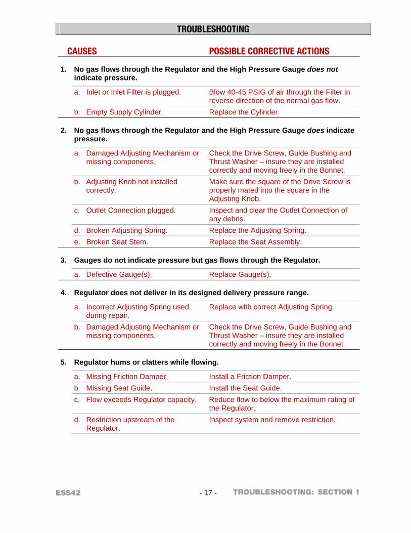
TROUBLESHOOTING
CAUSES POSSIBLE CORRECTIVE ACTIONS
1. No gas flows through the Regulator and the High Pressure Gauge does not indicate pressure.
a. Inlet or Inlet Filter is plugged. Blow 40-45 PSIG of air through the Filter in reverse direction of the normal gas flow.
b. Empty Supply Cylinder. Replace the Cylinder.
2. No gas flows through the Regulator and the High Pressure Gauge does indicate pressure.
a. Damaged Adjusting Mechanism or missing components.
Check the Drive Screw, Guide Bushing and Thrust Washer – insure they are installed correctly and moving freely in the Bonnet.
b. Adjusting Knob not installed correctly.
Make sure the square of the Drive Screw is properly mated into the square in the Adjusting Knob.
c. Outlet Connection plugged. Inspect and clear the Outlet Connection of any debris.
d. Broken Adjusting Spring. Replace the Adjusting Spring. e. Broken Seat Stem. Replace the Seat Assembly.
3. Gauges do not indicate pressure but gas flows through the Regulator.
a. Defective Gauge(s). Replace Gauge(s).
4. Regulator does not deliver in its designed delivery pressure range.
a. Incorrect Adjusting Spring used during repair.
Replace with correct Adjusting Spring.
b. Damaged Adjusting Mechanism or missing components.
Check the Drive Screw, Guide Bushing and Thrust Washer – insure they are installed correctly and moving freely in the Bonnet.
5. Regulator hums or clatters while flowing.
a. Missing Friction Damper. Install a Friction Damper. b. Missing Seat Guide. Install the Seat Guide. c. Flow exceeds Regulator capacity. Reduce flow to below the maximum rating of
the Regulator. d. Restriction upstream of the
Regulator. Inspect system and remove restriction.
TROUBLESHOOTING:
ESS42 - 18 - SECTION 1
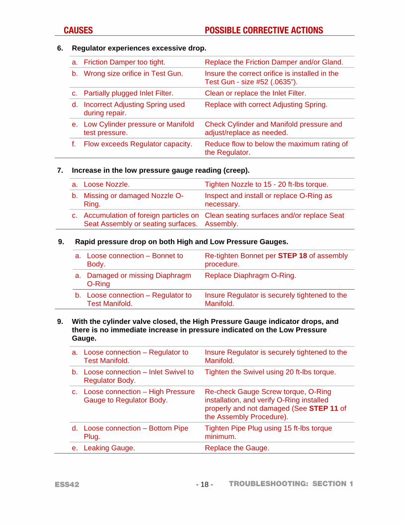
CAUSES POSSIBLE CORRECTIVE ACTIONS
6. Regulator experiences excessive drop.
a. Friction Damper too tight. Replace the Friction Damper and/or Gland. b. Wrong size orifice in Test Gun. Insure the correct orifice is installed in the
Test Gun - size #52 (.0635”). c. Partially plugged Inlet Filter. Clean or replace the Inlet Filter. d. Incorrect Adjusting Spring used
during repair. Replace with correct Adjusting Spring.
e. Low Cylinder pressure or Manifold test pressure.
Check Cylinder and Manifold pressure and adjust/replace as needed.
f. Flow exceeds Regulator capacity. Reduce flow to below the maximum rating of the Regulator.
7. Increase in the low pressure gauge reading (creep).
a. Loose Nozzle. Tighten Nozzle to 15 - 20 ft-lbs torque. b. Missing or damaged Nozzle O-
Ring. Inspect and install or replace O-Ring as necessary.
c. Accumulation of foreign particles on Seat Assembly or seating surfaces.
Clean seating surfaces and/or replace Seat Assembly.
9. Rapid pressure drop on both High and Low Pressure Gauges.
a. Loose connection – Bonnet to Body.
Re-tighten Bonnet per STEP 18 of assembly procedure.
a. Damaged or missing Diaphragm O-Ring
Replace Diaphragm O-Ring.
b. Loose connection – Regulator to Test Manifold.
Insure Regulator is securely tightened to the Manifold.
9. With the cylinder valve closed, the High Pressure Gauge indicator drops, and there is no immediate increase in pressure indicated on the Low Pressure Gauge.
a. Loose connection – Regulator to Test Manifold.
Insure Regulator is securely tightened to the Manifold.
b. Loose connection – Inlet Swivel to Regulator Body.
Tighten the Swivel using 20 ft-lbs torque.
c. Loose connection – High Pressure Gauge to Regulator Body.
Re-check Gauge Screw torque, O-Ring installation, and verify O-Ring installed properly and not damaged (See STEP 11 of the Assembly Procedure).
d. Loose connection – Bottom Pipe Plug.
Tighten Pipe Plug using 15 ft-lbs torque minimum.
e. Leaking Gauge. Replace the Gauge.
TROUBLESHOOTING:
ESS42 - 19 - SECTION 1
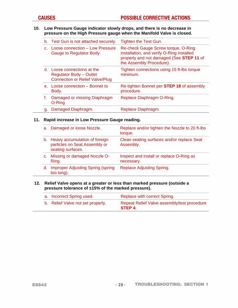
CAUSES POSSIBLE CORRECTIVE ACTIONS
10. Low Pressure Gauge indicator slowly drops, and there is no decrease in pressure on the High Pressure gauge when the Manifold Valve is closed.
b. Test Gun is not attached securely. Tighten the Test Gun. c. Loose connection – Low Pressure
Gauge to Regulator Body. Re-check Gauge Screw torque, O-Ring installation, and verify O-Ring installed properly and not damaged (See STEP 11 of the Assembly Procedure).
d. Loose connections at the Regulator Body – Outlet Connection or Relief Valve/Plug
Tighten connections using 15 ft-lbs torque minimum.
e. Loose connection – Bonnet to Body.
Re-tighten Bonnet per STEP 18 of assembly procedure.
f. Damaged or missing Diaphragm O-Ring
Replace Diaphragm O-Ring.
g. Damaged Diaphragm. Replace Diaphragm.
11. Rapid increase in Low Pressure Gauge reading.
a. Damaged or loose Nozzle. Replace and/or tighten the Nozzle to 20 ft-lbs torque.
b. Heavy accumulation of foreign particles on Seat Assembly or seating surfaces.
Clean seating surfaces and/or replace Seat Assembly.
c. Missing or damaged Nozzle O-Ring.
Inspect and install or replace O-Ring as necessary.
d. Improper Adjusting Spring (spring too long).
Replace Adjusting Spring.
12. Relief Valve opens at a greater or less than marked pressure (outside a pressure tolerance of ±15% of the marked pressure).
a. Incorrect Spring used. Replace with correct Spring. b. Relief Valve not set properly. Repeat Relief Valve assembly/test procedure
STEP 4.
TROUBLESHOOTING:
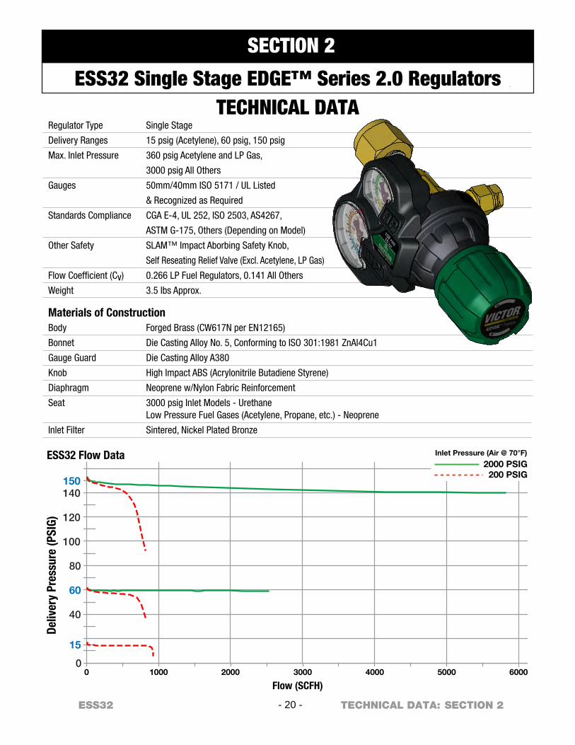
Regulator Type
Delivery Ranges
Max. Inlet Pressure
Gauges
Standards Compliance
Other Safety
Flow Coefficient (Cv)
Weight
Single Stage
15 psig (Acetylene), 60 psig, 150 psig
360 psig Acetylene and LP Gas,
3000 psig All Others
50mm/40mm ISO 5171 / UL Listed
& Recognized as Required
CGA E-4, UL 252, ISO 2503, AS4267,
ASTM G-175, Others (Depending on Model)
SLAM™ Impact Aborbing Safety Knob,
Self Reseating Relief Valve (Excl. Acetylene, LP Gas)
0.266 LP Fuel Regulators, 0.141 All Others
3.5 lbs Approx.
Materials of ConstructionBody
Bonnet
Gauge Guard
Knob
Diaphragm
Seat
Inlet Filter
Forged Brass (CW617N per EN12165)
Die Casting Alloy No. 5, Conforming to ISO 301:1981 ZnAl4Cu1
Die Casting Alloy A380
High Impact ABS (Acrylonitrile Butadiene Styrene)
Neoprene w/Nylon Fabric Reinforcement
3000 psig Inlet Models - UrethaneLow Pressure Fuel Gases (Acetylene, Propane, etc.) - Neoprene
Sintered, Nickel Plated Bronze
1000 2000 3000
15
40
60
80
100
120
140150
4000 5000 600000
Deliv
ery
Pres
sure
(PSI
G)
Flow (SCFH)
ESS32 Flow Data Inlet Pressure (Air @ 70°F)
2000 PSIG200 PSIG
- 20 -ESS32 SECTION 2TECHNICAL DATA:
SECTION 2
ESS32 Single Stage EDGE™ Series 2.0 RegulatorsTECHNICAL DATA
ESS32 - 21 - SECTION 2 GENERAL:
SERVICE & REPAIR – BEFORE YOU BEGIN ESS32 Single Stage EDGE™ Series 2.0 Regulators
m WARNING! m Apparatus improperly operated, maintained or repaired can be dangerous!
Service and repair of VICTOR apparatus should only be performed by a Qualified Repair Technician. The term “Qualified Repair Technician” refers to repair personnel capable of servicing apparatus in strict accordance with all applicable Victor “Parts & Service Bulletins” and literature. Improper service or repair, or modification of the product, could result in damage to the product or injury to the operator. Protect your investment! Some parts and accessories manufactured by others may fit VICTOR apparatus, but not conform to VICTOR’s exacting standards for quality, fit and function. For your own protection and the protection of your investment, specify and use only VICTOR genuine parts and accessories. It’s the only way to guarantee the level of performance, safety and reliability that you expect from VICTOR.
GLOSSARY – COMMONLY USED TERMS
OUTLET PRESSURE: The pressure measured at the Regulator’s outlet port.
INLET PRESSURE: The pressure measured immediately at the Regulator’s entry.
DROP: A change in outlet pressure from a no-flow to flowing condition while the inlet pressure remains constant.
RISE: An increase in outlet pressure as the inlet pressure decreases.
CREEP: A gradual increase in outlet pressure.
RECOMMENDED TOOLS & SUPPLIES FOR REPAIR PROCEDURES
Inlet Swivel Assembly Plug (SEE TABLE 1) Bench Vise 9/16”, 11/16”, 3/4”, 1-5/8” Sockets Torque Wrench for 4 - 36 in-lbs ranges Torque Wrench for 15 - 50 ft-lbs ranges 1/4” Hex Key Torx T-8 and T-15 Drivers Philips and Flat Head Screwdrivers Leverage Bar – Part No. 1420-0299
(To support body and install inlet)
O-Ring Installation Tool – Part No. 1420-0344 (To ensure proper Gauge O-Ring positioning)
Oxygen-compatible Teflon® Tape Loctite® #222 Threadlocker CHRISTO-LUBE® #129 Lubricant.
TABLE 1 – Inlet Swivel Assembly Plugs
Inlet Connection
Inlet Swivel Assembly Plug P/N
CGA 300 1420-0013 CGA 320 1420-0127 CGA 326 1420-0219 CGA 346 1420-0220 CGA 350 1420-0009 CGA 510 1420-0015 CGA 540 1420-0014 CGA 580 1420-0134 CGA 590 1420-0135
“992” (British BS3) 1420-0145 “993” (British BS2) 1420-0146
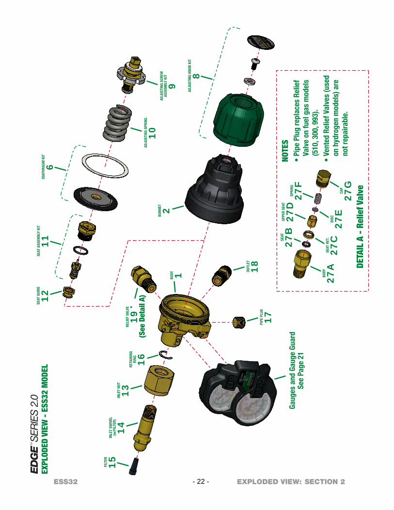
SEAT
ASS
EMBL
Y KI
T
11
BODY 1
RELI
EF V
ALVE
19
*
(See
Det
ail A
)
EXPL
ODED
VIE
W -
ESS
32 M
ODEL
BONN
ET 2
Gaug
es a
nd G
auge
Gua
rdSe
e Pa
ge 2
1
DIAP
HRAG
M K
IT
6
RETA
ININ
GRI
NG 16
INLE
T NU
T
13IN
LET
SWIV
EL(w
/FIL
TER)
14
FILT
ER
15
PIPE
PLU
G
17
OUTL
ET
18
SEAT
GUI
DE
12
ADJU
STIN
G SP
RING
10AD
JUST
ING
SCRE
WAS
SEM
BLY
KIT
9AD
JUST
ING
KNOB
KIT
8
BODY
27A
SEAT
RET
.
27C
DISC
27E
SEAT
27B
UPPE
R SE
AT
27D
SPRI
NG
27F
CAP
27G
DETA
IL A
- R
elie
f Val
ve
NOTE
S•
Pipe
Plu
g re
plac
es R
elie
f Va
lve
on fu
el g
as m
odel
s (5
10, 3
00, 9
93).
• Ve
nted
Rel
ief V
alve
s (u
sed
on h
ydro
gen
mod
els)
are
no
t rep
aira
ble.
- 22 -ESS32 SECTION 2EXPLODED VIEW:
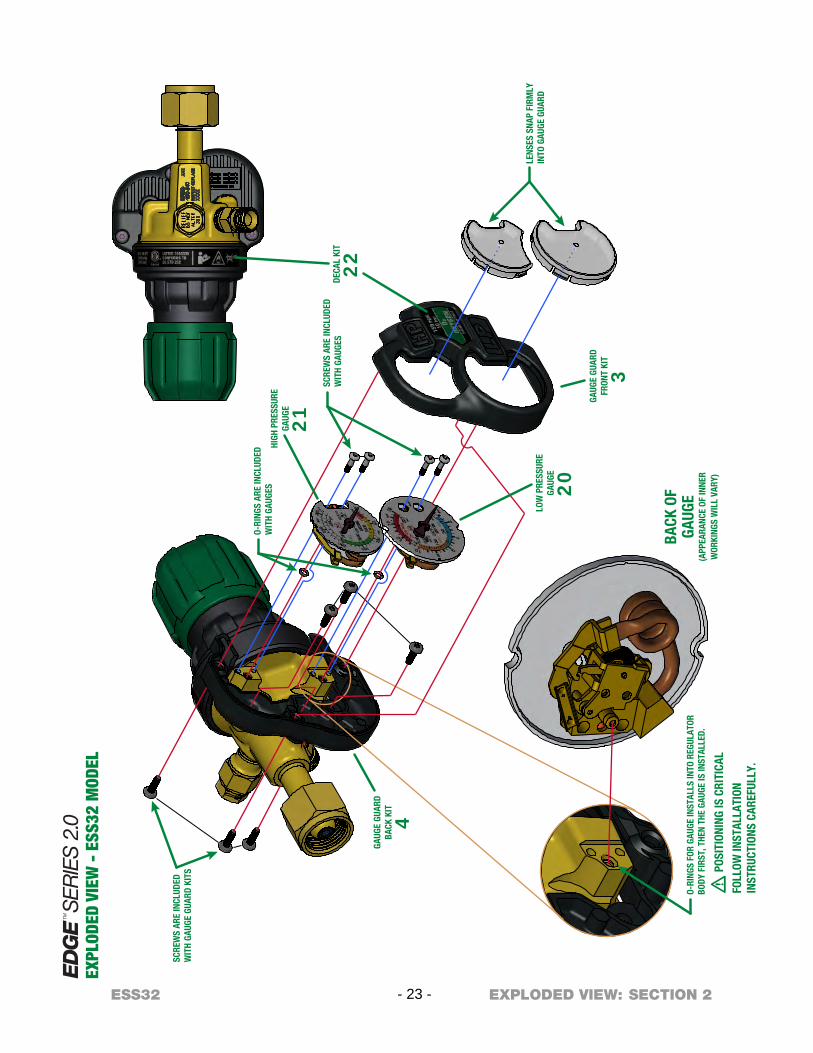
BACK
OF
GAUG
E(A
PPEA
RANC
E OF
INNE
RW
ORKI
NGS
WIL
L VA
RY)
m P
OSIT
IONI
NG IS
CRI
TICA
L
FOLL
OW IN
STAL
LATI
ONIN
STRU
CTIO
NS C
AREF
ULLY
.
LENS
ES S
NAP
FIRM
LYIN
TO G
AUGE
GUA
RD
SCRE
WS
ARE
INCL
UDED
WIT
H GA
UGES
O-RI
NGS
ARE
INCL
UDED
WIT
H GA
UGES
DECA
L KI
T
22
HIGH
PRE
SSUR
EGA
UGE
21
LOW
PRE
SSUR
EGA
UGE
20GA
UGE
GUAR
DFR
ONT
KIT
3
SCRE
WS
ARE
INCL
UDED
WIT
H GA
UGE
GUAR
D KI
TS
GAUG
E GU
ARD
BACK
KIT
4
O-RI
NGS
FOR
GAUG
E IN
STAL
LS IN
TO R
EGUL
ATOR
BODY
FIR
ST, T
HEN
THE
GAUG
E IS
INST
ALLE
D.
EXPL
ODED
VIE
W -
ESS
32 M
ODEL
- 23 -ESS32 SECTION 2EXPLODED VIEW:
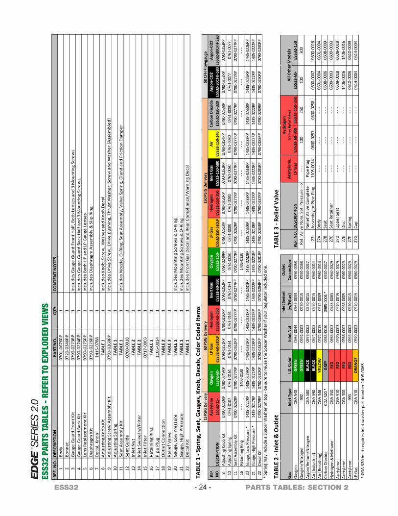
REF.
NO
.D
ESCR
IPTI
ON
PART
NO
.Q
TYCO
NTE
NT
NO
TES
1Bo
dy07
01-0
676R
P1
2Bo
nnet
0720
-034
6RP
13
Gau
ge G
uard
Fro
nt K
it07
90-0
273R
P1
Incl
udes
Gau
ge G
uard
Fro
nt H
alf,
Bot
h Le
nses
and
3 M
ounti
ng S
crew
s4
Gau
ge G
uard
Bac
k Ki
t07
90-0
274R
P1
Incl
udes
Gau
ge G
uard
Bac
k H
alf a
nd 3
Mou
nting
Scr
ews
5Le
ns R
epla
cem
ent K
it07
90-0
275R
P1
Incl
udes
Bot
h H
P an
d LP
Gau
ge L
ense
s6
Dia
phra
gm K
it07
90-0
276R
P1
Incl
udes
Dia
phra
gm A
ssem
bly
& S
lip R
ing
7D
ecal
, Kno
b14
15-0
788
18
Adj
ustin
g Kn
ob K
itTA
BLE
11
Incl
udes
Kno
b, S
crew
, Was
her a
nd K
nob
Dec
al9
Adj
ustin
g Sc
rew
Ass
embl
y Ki
t 07
90-0
260R
P1
Incl
udes
Dri
ve S
crew
, Dri
ve B
ushi
ng, T
hrus
t Was
her,
Scr
ew a
nd W
ashe
r (A
ssem
bled
)10
Adj
ustin
g Sp
ring
TABL
E 1
111
Seat
Ass
embl
y Ki
t TA
BLE
11
Incl
udes
Noz
zle,
O-R
ing,
Sea
t Ass
embl
y, V
alve
Spr
ing,
Gla
nd a
nd F
ricti
on D
ampe
r12
Seat
Gui
de07
08-0
018
113
Inle
t Nut
TABL
E 2
114
Inle
t Sw
ivel
w/F
il ter
TABL
E 2
115
Inle
t Filt
er07
17-0
003
116
Reta
inin
g Ri
ngTA
BLE
11
17Pi
pe P
lug
1105
-001
41
18O
utle
t Con
necti
onTA
BLE
21
19Re
lief V
alve
TABL
E 3
120
Gau
ge, L
ow P
ress
ure
TABL
E 1
1In
clud
es M
ounti
ng S
crew
s &
O-R
ing
21G
auge
, Hig
h Pr
essu
reTA
BLE
11
Incl
udes
Mou
nting
Scr
ews
& O
-Rin
g22
Dec
al K
itTA
BLE
11
Incl
udes
Fro
nt G
as D
ecal
and
Rea
r Com
plia
nce/
War
ning
Dec
al
15 P
SIG
Deliv
ery
Acet
ylen
eO
xyge
nLP
Gas
Hydr
ogen
Iner
t Gas
Oxy
gen
LP G
asHy
drog
enIn
ert G
asAi
rCa
rbon
Dio
xide
Argo
n-CO
2Ar
gon-
CO2
REF.
NO
.DE
SCRI
PTIO
NES
S32-
15-
ESS3
2-60
-ES
S32-
60-5
10LP
ESS3
2-60
-350
ESS3
2-60
-580
ESS3
2-15
0-ES
S32-
150-
510L
PES
S32-
150-
350
ESS3
2-15
0-58
0ES
S32-
150-
346
ESS3
2-15
0-32
0ES
S32-
80CF
H-58
0ES
S32-
80CF
H-32
08
Adju
sting
Kno
b Ki
t07
90-0
250R
P07
90-0
249R
P07
90-0
251R
P07
90-0
250R
P07
90-0
252R
P07
90-0
249R
P07
90-0
251R
P07
90-0
250R
P07
90-0
252R
P07
90-0
254R
P07
90-0
253R
P07
90-0
252R
P07
90-0
253R
P10
Adju
sting
Spr
ing
0761
-010
707
61-0
161
0761
-016
107
61-0
161
0761
-016
107
61-0
080
0761
-008
007
61-0
080
0761
-008
007
61-0
080
0761
-008
007
61-0
077
0761
-007
711
Seat
Ass
embl
y Ki
t07
90-0
262R
P07
90-0
277R
P07
90-0
262R
P07
90-0
277R
P07
90-0
277R
P07
90-0
277R
P07
90-0
262R
P07
90-0
277R
P07
90-0
277R
P07
90-0
277R
P07
90-0
277R
P07
90-0
277R
P07
90-0
277R
P16
Reta
inin
g Ri
ng- -
-14
06-0
130
- - -
- - -
- - -
1406
-013
0- -
-- -
-- -
-- -
-- -
-- -
-- -
-20
Gaug
e, Lo
w P
ress
ure
*14
35-0
227R
P14
35-0
229R
P14
35-0
231R
P14
35-0
231R
P14
35-0
231R
P14
35-0
232R
P14
35-0
233R
P14
35-0
233R
P14
35-0
233R
P14
35-0
233R
P14
35-0
233R
P14
35-0
226R
P14
35-0
226R
P21
Gaug
e, H
igh
Pres
sure
*14
35-0
217R
P14
35-0
221R
P14
35-0
218R
P14
35-0
222R
P14
35-0
222R
P14
35-0
221R
P14
35-0
218R
P14
35-0
222R
P14
35-0
222R
P14
35-0
222R
P14
35-0
222R
P14
35-0
222R
P14
35-0
222R
P22
Deca
l Kit
0790
-027
9RP
0790
-028
0RP
0790
-028
2RP
0790
-028
6RP
0790
-028
4RP
0790
-028
1RP
0790
-028
3RP
0790
-028
7RP
0790
-028
5RP
0790
-028
8RP
0790
-028
9RP
0790
-029
0RP
0790
-029
0RP
60 P
SIG
Del
iver
y15
0 PS
IG D
eliv
ery
50 C
FH F
low
gaug
e
Inle
t Sw
ivel
Out
let
Inle
t Typ
eI.D
. Col
orIn
let N
ut(w
/Filt
er)
Conn
ectio
nCG
A 54
0G
REEN
0967
-004
409
67-0
033
0950
-006
899
2G
REEN
0992
-000
309
70-0
015
0950
-006
8CG
A 58
0BL
ACK
0973
-000
309
70-0
015
0950
-001
7CG
A 59
0BL
ACK
0974
-000
309
70-0
015
0960
-001
4CG
A 34
6YE
LLO
W09
72-0
015
0972
-000
909
60-0
014
CGA
320
*G
REY
0985
-003
009
85-0
004
*09
50-0
017
CGA
350
RED
0983
-000
309
83-0
005
0960
-002
9CG
A 51
0RE
D09
70-0
003
0970
-001
509
60-0
029
CGA
300
RED
0968
-000
309
68-0
0 05
0960
-002
999
3RE
D09
93-0
003
0970
-001
509
60-0
029
C GA
510
ORA
NG
E09
70-0
003
0970
-001
509
60-0
029
Argo
n/He
lium
/Nitr
ogen
LP G
as
Gas
Oxy
gen
Oxy
gen/
Nitr
ogen
Air (
Indu
stria
l)Ai
r (Br
eath
ing)
Carb
on D
ioxi
deHy
drog
en &
Met
hane
Acet
ylen
eAc
etyl
ene
Acet
ylen
e
Acet
ylen
e,RE
F. N
O.
DESC
RIPT
ION
LP G
asES
S32-
60-3
50ES
S32-
150-
350
ESS3
2-60
-ES
S32-
150
Rel.
Valv
e N
om. S
et P
ress
ure
-->
- - -
100
250
100
300
27A
Body
- - -
0601
-000
406
01-0
004
27B
Seat
- - -
0608
-000
606
08-0
009
27C
Seat
Ret
aine
r- -
-- -
-- -
-06
09-0
003
0609
-000
327
DUp
per S
eat
- - -
- - -
- - -
0608
-001
806
08-0
018
27E
Disc
- - -
- - -
- - -
1406
-001
614
06-0
016
27F
Sprin
g- -
-06
10-0
006
0610
-000
927
GCa
p- -
-- -
-- -
-06
14-0
004
0614
-000
4
0600
-025
8
Hydr
ogen
(V
ente
d Re
lief V
alve
)
0600
-001
6
All O
ther
Mod
els
Relie
f Val
ve C
ompl
ete
Asse
mbl
y or
Pip
e Pl
ug27
Pipe
Plu
g11
05-0
014
0600
-025
706
00-0
007
- - -
- - -
- - -
- - -
- - -
- - -
TABL
E 3
- Rel
ief V
alve
*TABL
E 1
- Spr
ing,
Sea
t, G
auge
s, K
nob,
Dec
als,
Col
or C
oded
Item
s
Sprin
g m
ay in
clud
e a
Spac
er W
ashe
r on
top
- be
sure
to re
use
the
Spac
er W
ashe
r if y
our R
egul
ator
incl
uded
one
.
TABL
E 2
- Inl
et &
Out
let
* CG
A 32
0 in
let r
equi
res i
nlet
was
her p
art n
umbe
r 140
8-00
65.
ESS3
2 PA
RTS
TABL
ES -
REF
ER T
O EX
PLOD
ED V
IEW
S
- 24 -ESS32 SECTION 2PARTS TABLES:
ESS32 - 25 - SECTION 2
SERVICE & REPAIR – PROCEDURES ESS32 Single Stage EDGE™ Series 2.0 Regulators
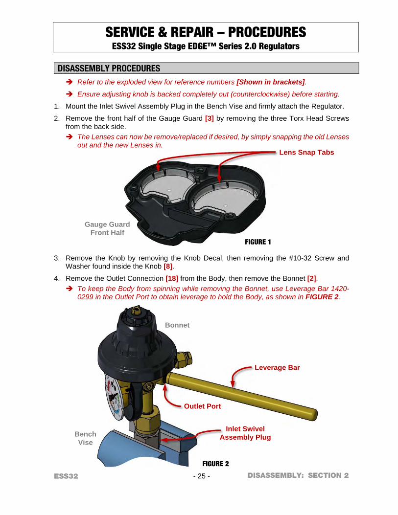
DISASSEMBLY PROCEDURES Refer to the exploded view for reference numbers [Shown in brackets].
Ensure adjusting knob is backed completely out (counterclockwise) before starting.
1. Mount the Inlet Swivel Assembly Plug in the Bench Vise and firmly attach the Regulator.
2. Remove the front half of the Gauge Guard [3] by removing the three Torx Head Screws from the back side. The Lenses can now be remove/replaced if desired, by simply snapping the old Lenses
out and the new Lenses in.
3. Remove the Knob by removing the Knob Decal, then removing the #10-32 Screw and Washer found inside the Knob [8].
4. Remove the Outlet Connection [18] from the Body, then remove the Bonnet [2]. To keep the Body from spinning while removing the Bonnet, use Leverage Bar 1420-
0299 in the Outlet Port to obtain leverage to hold the Body, as shown in FIGURE 2.
Bench Vise
Bonnet
FIGURE 2
Gauge Guard Front Half
FIGURE 1
DISASSEMBLY:
Leverage Bar
Inlet Swivel Assembly Plug
Outlet Port
Lens Snap Tabs
ESS32 - 26 - SECTION 2
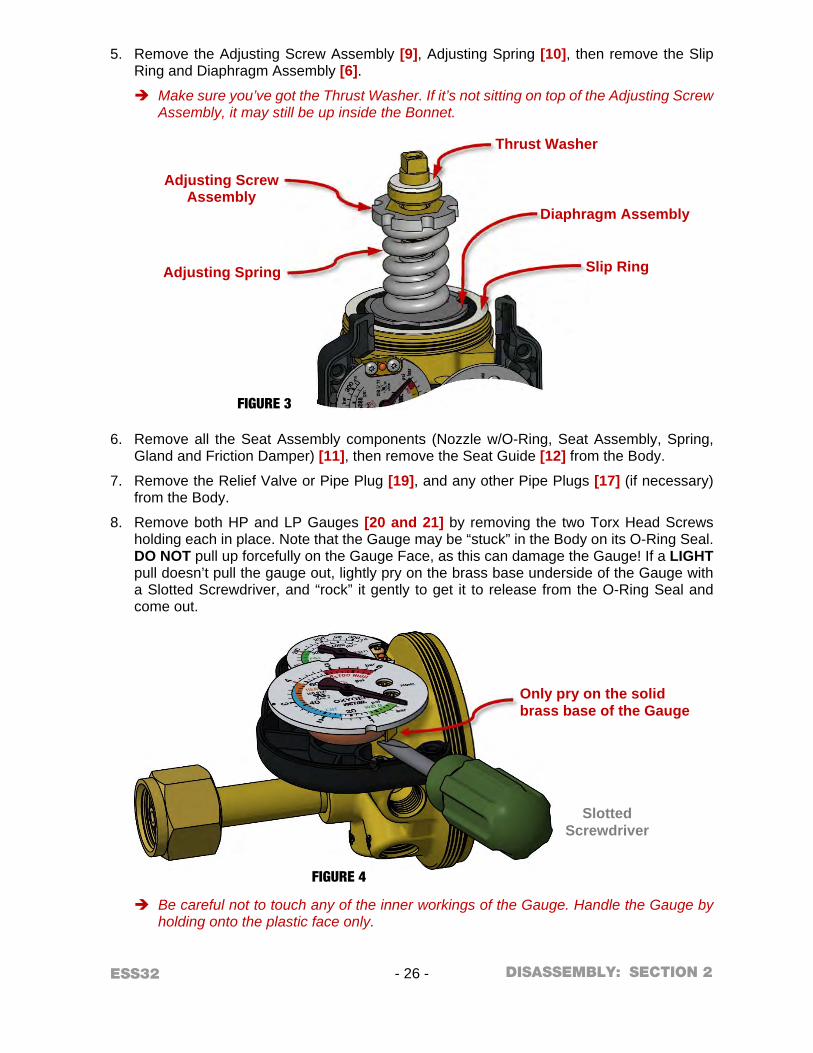
5. Remove the Adjusting Screw Assembly [9], Adjusting Spring [10], then remove the Slip Ring and Diaphragm Assembly [6].
Make sure you’ve got the Thrust Washer. If it’s not sitting on top of the Adjusting Screw Assembly, it may still be up inside the Bonnet.
6. Remove all the Seat Assembly components (Nozzle w/O-Ring, Seat Assembly, Spring, Gland and Friction Damper) [11], then remove the Seat Guide [12] from the Body.
7. Remove the Relief Valve or Pipe Plug [19], and any other Pipe Plugs [17] (if necessary) from the Body.
8. Remove both HP and LP Gauges [20 and 21] by removing the two Torx Head Screws holding each in place. Note that the Gauge may be “stuck” in the Body on its O-Ring Seal. DO NOT pull up forcefully on the Gauge Face, as this can damage the Gauge! If a LIGHT pull doesn’t pull the gauge out, lightly pry on the brass base underside of the Gauge with a Slotted Screwdriver, and “rock” it gently to get it to release from the O-Ring Seal and come out.
Be careful not to touch any of the inner workings of the Gauge. Handle the Gauge by holding onto the plastic face only.
Slotted Screwdriver
FIGURE 4
FIGURE 3
DISASSEMBLY:
Only pry on the solid brass base of the Gauge
Slip Ring
Diaphragm Assembly
Adjusting Screw Assembly
Adjusting Spring
Thrust Washer
ESS32 - 27 - SECTION 2
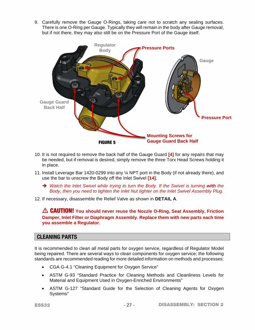
9. Carefully remove the Gauge O-Rings, taking care not to scratch any sealing surfaces.
There is one O-Ring per Gauge. Typically they will remain in the body after Gauge removal, but if not there, they may also still be on the Pressure Port of the Gauge itself.
10. It is not required to remove the back half of the Gauge Guard [4] for any repairs that may be needed, but if removal is desired, simply remove the three Torx Head Screws holding it in place.
11. Install Leverage Bar 1420-0299 into any ¼ NPT port in the Body (if not already there), and use the bar to unscrew the Body off the Inlet Swivel [14].
Watch the Inlet Swivel while trying to turn the Body. If the Swivel is turning with the Body, then you need to tighten the Inlet Nut tighter on the Inlet Swivel Assembly Plug.
12. If necessary, disassemble the Relief Valve as shown in DETAIL A.
m CAUTION! You should never reuse the Nozzle O-Ring, Seat Assembly, Friction Damper, Inlet Filter or Diaphragm Assembly. Replace them with new parts each time you assemble a Regulator.
CLEANING PARTS It is recommended to clean all metal parts for oxygen service, regardless of Regulator Model being repaired. There are several ways to clean components for oxygen service; the following standards are recommended reading for more detailed information on methods and processes:
CGA G-4.1 “Cleaning Equipment for Oxygen Service”
ASTM G-93 “Standard Practice for Cleaning Methods and Cleanliness Levels for Material and Equipment Used in Oxygen-Enriched Environments”
ASTM G-127 “Standard Guide for the Selection of Cleaning Agents for Oxygen Systems”
Gauge
FIGURE 5
Regulator Body
Gauge Guard Back Half
DISASSEMBLY:
Pressure Ports
Pressure Port
Mounting Screws for Gauge Guard Back Half
ESS32 - 28 - SECTION 2
For metal parts, VICTOR suggests using CCI Envirospray Liquid, used per the manufacturer's instructions, followed by a hot water rinse and thorough drying. Additional information can be found at http://www.ccichemical.com.
DO NOT allow non-metal parts to come in contact with cleaning solvents. Cleaning solvents can cause non-metal parts to swell and/or crack. To clean these parts, use a non-petroleum based mild soap solution, followed by a thorough rinsing in water. Dry parts completely prior to reassembling.
ASSEMBLY PROCEDURES Refer to the exploded view for reference numbers [Shown in brackets]
m IMPORTANT NOTES ABOUT SEALING PIPE THREADS: When using Teflon® tape where noted: Apply two to three layers around the
threads, leaving the first thread clean. Insure your Teflon® tape is oxygen-compatible.
When using Loctite® #222 Threadlocker where noted: Apply two to three drops to the second and third thread, leaving the first thread clean.
1. Install a new Filter [15] into the Inlet Swivel (or replace entire Inlet Swivel w/Filter installed [14]), and apply Teflon® tape to the Inlet Swivel threads.
2. If not already in place, mount the Inlet Swivel Assembly Plug back in the Bench Vise. Firmly attach the Inlet Swivel and Inlet Nut [13] onto the Inlet Swivel Assembly Plug. Install Retaining Ring [16], if equipped.
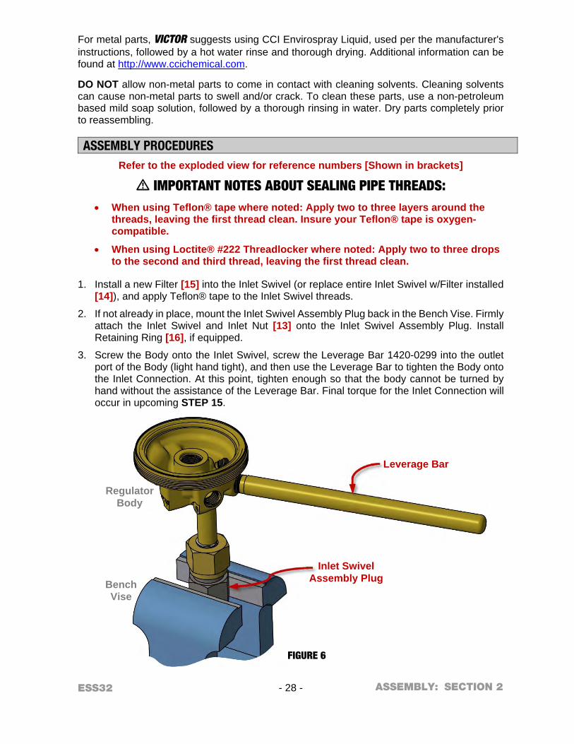
3. Screw the Body onto the Inlet Swivel, screw the Leverage Bar 1420-0299 into the outlet port of the Body (light hand tight), and then use the Leverage Bar to tighten the Body onto the Inlet Connection. At this point, tighten enough so that the body cannot be turned by hand without the assistance of the Leverage Bar. Final torque for the Inlet Connection will occur in upcoming STEP 15.
Bench Vise
Regulator Body
FIGURE 6
ASSEMBLY:
Leverage Bar
Inlet Swivel Assembly Plug
ESS32 - 29 - SECTION 2
4. Preassemble the Relief Valve (if so equipped): Assemble (or reassemble) the Relief Valve [19] as shown in DETAIL A. Use no lubricants or sealants. If your Regulator model has a Pipe Plug instead of a Relief Valve, or if your Relief Valve is already assembled and tested, you can skip to STEP 8.
5. To ensure proper Relief Valve performance, perform the following test procedures before assembling the Relief Valve in the Regulator.
a. Attach the Relief Valve to a 450 PSIG source of oil-free air or dry nitrogen.
b. Slowly pressurize the Relief Valve, increasing to the recommended blow-off pressure listed in TABLE 2 below. Note that VICTOR Relief Valves are stamped with their nominal set pressure, in case you’re unsure which Relief Valve you have.
Non-Vented Relief Valves:
If the Relief Valve vents before the minimum blow-off pressure is reached, then a second Disc [27E] may be added. If it still vents, then the Spring [27F] must be replaced.
Vented Relief Valves:
If the Vented Relief Valve fails to vent within the recommended blow-off pressure, reset the Adjusting Screw [27J] as necessary and perform this step again. Make sure you fully bleed off all pressure each time you test for blow-off pressure.
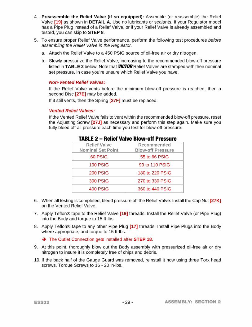
TABLE 2 – Relief Valve Blow-off Pressure Relief Valve
Nominal Set Point Recommended
Blow-off Pressure
60 PSIG 55 to 66 PSIG
100 PSIG 90 to 110 PSIG
200 PSIG 180 to 220 PSIG
300 PSIG 270 to 330 PSIG
400 PSIG 360 to 440 PSIG
6. When all testing is completed, bleed pressure off the Relief Valve. Install the Cap Nut [27K] on the Vented Relief Valve.
7. Apply Teflon® tape to the Relief Valve [19] threads. Install the Relief Valve (or Pipe Plug) into the Body and torque to 15 ft-lbs.
8. Apply Teflon® tape to any other Pipe Plug [17] threads. Install Pipe Plugs into the Body where appropriate, and torque to 15 ft-lbs.
The Outlet Connection gets installed after STEP 18.
9. At this point, thoroughly blow out the Body assembly with pressurized oil-free air or dry nitrogen to insure it is completely free of chips and debris.
10. If the back half of the Gauge Guard was removed, reinstall it now using three Torx head screws. Torque Screws to 16 - 20 in-lbs.
ASSEMBLY:
ESS32 - 30 - SECTION 2
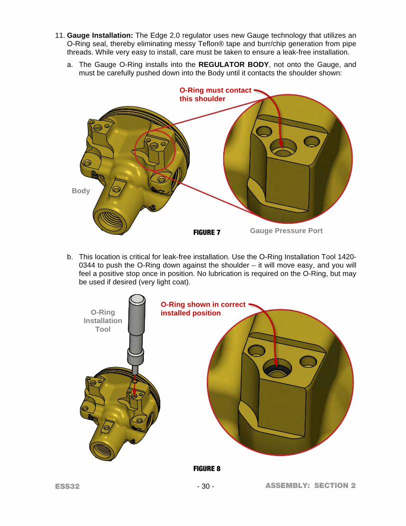
11. Gauge Installation: The Edge 2.0 regulator uses new Gauge technology that utilizes an
O-Ring seal, thereby eliminating messy Teflon® tape and burr/chip generation from pipe threads. While very easy to install, care must be taken to ensure a leak-free installation.
a. The Gauge O-Ring installs into the REGULATOR BODY, not onto the Gauge, and must be carefully pushed down into the Body until it contacts the shoulder shown:
b. This location is critical for leak-free installation. Use the O-Ring Installation Tool 1420-0344 to push the O-Ring down against the shoulder – it will move easy, and you will feel a positive stop once in position. No lubrication is required on the O-Ring, but may be used if desired (very light coat).
Gauge Pressure Port
Body
O-Ring Installation
Tool
FIGURE 7
FIGURE 8
ASSEMBLY:
O-Ring must contact this shoulder
O-Ring shown in correct installed position
ESS32 - 31 - SECTION 2
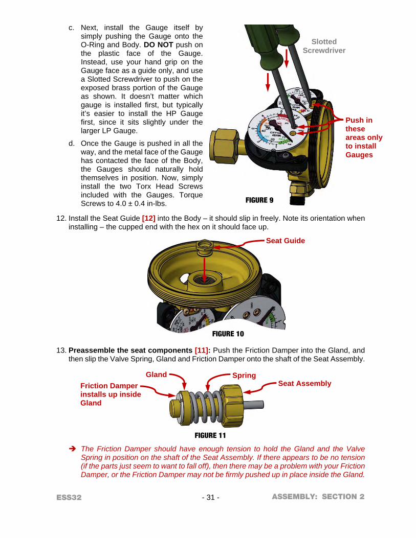
c. Next, install the Gauge itself by simply pushing the Gauge onto the O-Ring and Body. DO NOT push on the plastic face of the Gauge. Instead, use your hand grip on the Gauge face as a guide only, and use a Slotted Screwdriver to push on the exposed brass portion of the Gauge as shown. It doesn’t matter which gauge is installed first, but typically it’s easier to install the HP Gauge first, since it sits slightly under the larger LP Gauge.
d. Once the Gauge is pushed in all the way, and the metal face of the Gauge has contacted the face of the Body, the Gauges should naturally hold themselves in position. Now, simply install the two Torx Head Screws included with the Gauges. Torque Screws to 4.0 ± 0.4 in-lbs.
12. Install the Seat Guide [12] into the Body – it should slip in freely. Note its orientation when installing – the cupped end with the hex on it should face up.
13. Preassemble the seat components [11]: Push the Friction Damper into the Gland, and then slip the Valve Spring, Gland and Friction Damper onto the shaft of the Seat Assembly.
The Friction Damper should have enough tension to hold the Gland and the Valve Spring in position on the shaft of the Seat Assembly. If there appears to be no tension (if the parts just seem to want to fall off), then there may be a problem with your Friction Damper, or the Friction Damper may not be firmly pushed up in place inside the Gland.
Slotted Screwdriver
FIGURE 9
FIGURE 10
FIGURE 11
ASSEMBLY:
Push in these areas only to install Gauges
Seat Guide
Friction Damper installs up inside Gland
Gland Spring Seat Assembly
ESS32 - 32 - SECTION 2
14. Install the preassembled seat components into the Regulator Body – with the Friction Damper and Gland fitting down into the cup shape of the Seat Guide.
15. Apply a light coat of CHRISTO-LUBE® #129 Lubricant to the Nozzle O-Ring, and install the new O-Ring onto the Nozzle, taking care to guide it carefully over the Nozzle threads to avoid nicks or tears. Install the Nozzle into the Regulator Body and torque to 15 - 20 ft-lbs. Note that 15 - 20 ft-lbs is the same recommended torque for the Inlet Connection Swivel, so as you torque down the Nozzle, you’re also finish-tightening the Inlet Swivel to the correct torque value. Watch the Inlet Swivel while you torque down the Nozzle. If the Swivel is turning with
the Body, then you need to tighten the Inlet Nut tighter on the Inlet Swivel Assembly Plug. You want to be sure that the 15 - 20 ft-lbs torque is being applied to both the Nozzle threads and the Inlet Swivel threads.
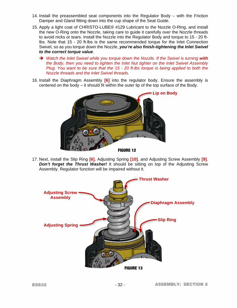
16. Install the Diaphragm Assembly [6] into the regulator body. Ensure the assembly is centered on the body – it should fit within the outer lip of the top surface of the Body.
17. Next, install the Slip Ring [6], Adjusting Spring [10], and Adjusting Screw Assembly [9]. Don’t forget the Thrust Washer! It should be sitting on top of the Adjusting Screw Assembly. Regulator function will be impaired without it.
FIGURE 12
FIGURE 13
ASSEMBLY:
Lip on Body
Thrust Washer
Slip Ring
Diaphragm Assembly
Adjusting Screw Assembly
Adjusting Spring
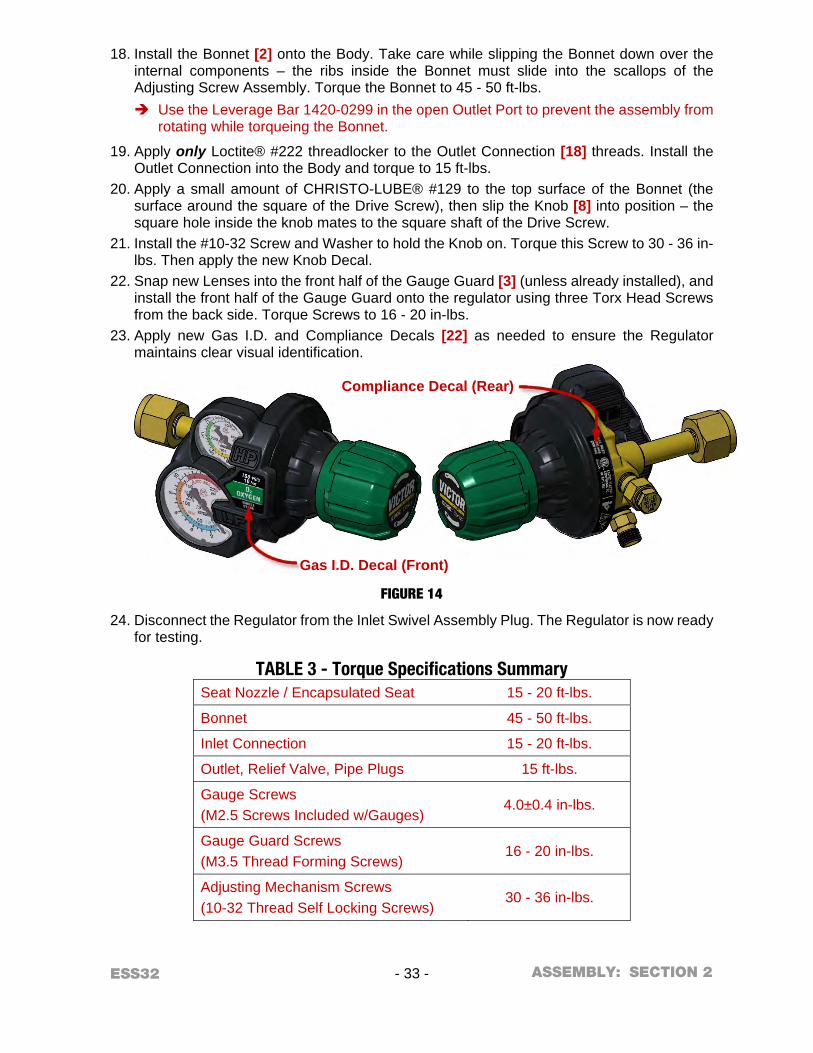
ESS32 - 33 - SECTION 2
18. Install the Bonnet [2] onto the Body. Take care while slipping the Bonnet down over the internal components – the ribs inside the Bonnet must slide into the scallops of the Adjusting Screw Assembly. Torque the Bonnet to 45 - 50 ft-lbs. Use the Leverage Bar 1420-0299 in the open Outlet Port to prevent the assembly from
rotating while torqueing the Bonnet.
19. Apply only Loctite® #222 threadlocker to the Outlet Connection [18] threads. Install the Outlet Connection into the Body and torque to 15 ft-lbs.
20. Apply a small amount of CHRISTO-LUBE® #129 to the top surface of the Bonnet (the surface around the square of the Drive Screw), then slip the Knob [8] into position – the square hole inside the knob mates to the square shaft of the Drive Screw.
21. Install the #10-32 Screw and Washer to hold the Knob on. Torque this Screw to 30 - 36 in-lbs. Then apply the new Knob Decal.
22. Snap new Lenses into the front half of the Gauge Guard [3] (unless already installed), and install the front half of the Gauge Guard onto the regulator using three Torx Head Screws from the back side. Torque Screws to 16 - 20 in-lbs.
23. Apply new Gas I.D. and Compliance Decals [22] as needed to ensure the Regulator maintains clear visual identification.
24. Disconnect the Regulator from the Inlet Swivel Assembly Plug. The Regulator is now ready for testing.
TABLE 3 - Torque Specifications Summary Seat Nozzle / Encapsulated Seat 15 - 20 ft-lbs.
Bonnet 45 - 50 ft-lbs.
Inlet Connection 15 - 20 ft-lbs.
Outlet, Relief Valve, Pipe Plugs 15 ft-lbs.
Gauge Screws (M2.5 Screws Included w/Gauges)
4.0±0.4 in-lbs.
Gauge Guard Screws (M3.5 Thread Forming Screws)
16 - 20 in-lbs.
Adjusting Mechanism Screws (10-32 Thread Self Locking Screws)
30 - 36 in-lbs.
FIGURE 14
ASSEMBLY:
Gas I.D. Decal (Front)
Compliance Decal (Rear)
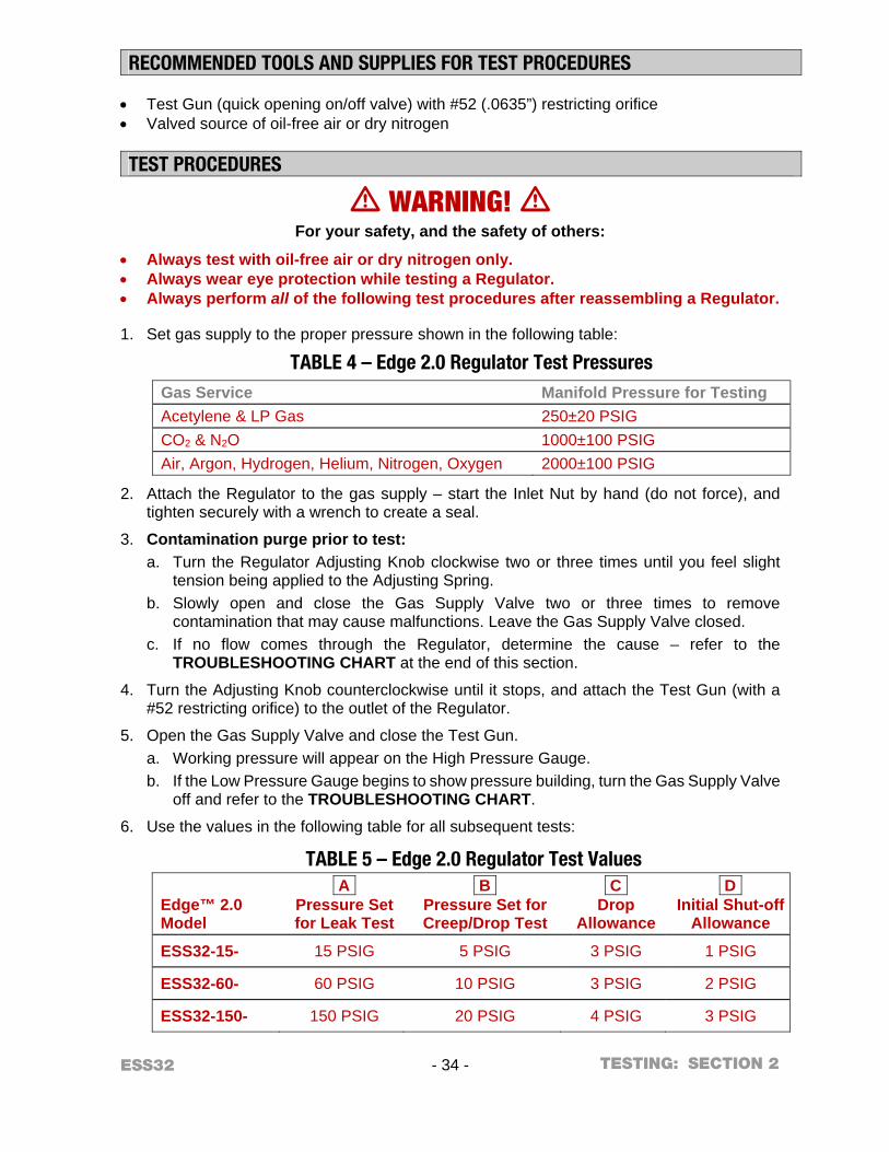
ESS32 - 34 - SECTION 2
RECOMMENDED TOOLS AND SUPPLIES FOR TEST PROCEDURES Test Gun (quick opening on/off valve) with #52 (.0635”) restricting orifice Valved source of oil-free air or dry nitrogen TEST PROCEDURES
m WARNING! m For your safety, and the safety of others:
Always test with oil-free air or dry nitrogen only. Always wear eye protection while testing a Regulator. Always perform all of the following test procedures after reassembling a Regulator.
1. Set gas supply to the proper pressure shown in the following table:
TABLE 4 – Edge 2.0 Regulator Test Pressures Gas Service Manifold Pressure for Testing
Acetylene & LP Gas 250±20 PSIG CO2 & N2O 1000±100 PSIG Air, Argon, Hydrogen, Helium, Nitrogen, Oxygen 2000±100 PSIG
2. Attach the Regulator to the gas supply – start the Inlet Nut by hand (do not force), and tighten securely with a wrench to create a seal.
3. Contamination purge prior to test: a. Turn the Regulator Adjusting Knob clockwise two or three times until you feel slight
tension being applied to the Adjusting Spring. b. Slowly open and close the Gas Supply Valve two or three times to remove
contamination that may cause malfunctions. Leave the Gas Supply Valve closed. c. If no flow comes through the Regulator, determine the cause – refer to the
TROUBLESHOOTING CHART at the end of this section.
4. Turn the Adjusting Knob counterclockwise until it stops, and attach the Test Gun (with a #52 restricting orifice) to the outlet of the Regulator.
5. Open the Gas Supply Valve and close the Test Gun. a. Working pressure will appear on the High Pressure Gauge. b. If the Low Pressure Gauge begins to show pressure building, turn the Gas Supply Valve
off and refer to the TROUBLESHOOTING CHART.
6. Use the values in the following table for all subsequent tests:
TABLE 5 – Edge 2.0 Regulator Test Values
Edge™ 2.0 Model
A Pressure Set for Leak Test
B Pressure Set for Creep/Drop Test
C Drop
Allowance
D Initial Shut-off
Allowance
ESS32-15- 15 PSIG 5 PSIG 3 PSIG 1 PSIG
ESS32-60- 60 PSIG 10 PSIG 3 PSIG 2 PSIG
ESS32-150- 150 PSIG 20 PSIG 4 PSIG 3 PSIG
TESTING:

ESS32 - 35 - SECTION 2
7. LEAK TEST
a. With the Test Gun closed and the Gas Supply Valve open, adjust the Regulator to deliver A PSIG.
b. Close the Gas Supply Valve and turn the Adjusting Knob one turn counterclockwise. c. Observe the Low Pressure and High Pressure Gauges for five (5) minutes:
1. If the High Pressure Gauge reading drops, there is a leak in the Gas Supply Valve, Inlet Connection, High Pressure Gauge or the plugged high pressure port.
2. If the Low Pressure Gauge reading drops, there is a leak in the downstream equipment, Low Pressure Gauge, Outlet Connection or Relief Valve port.
3. If the High Pressure Gauge reading drops at the same time the Low Pressure Gauge reading increases, there is a leak in the Regulator Seat.
d. If any leaks are found, isolate if possible using a liquid leak detector, disassemble and repair or replace parts as needed, and start the test over again. Refer to TROUBLESHOOTING CHART for more detailed cause and possible corrective action information.
8. DROP TEST a. With the Test Gun closed and the Gas Supply Valve open, adjust the Regulator to
deliver B PSIG. b. Open the Test Gun and note the new indicated delivery pressure. Drop (indicated
pressure static minus indicated pressure flowing) must not exceed C PSIG.
9. CREEP TEST / SLOW SHUT-OFF TEST a. With the Test Gun closed and the Gas Supply Valve open, adjust the Regulator to
deliver B PSIG. b. Open and close the Test Gun several times to stabilize the Regulator. Leave the test
gun closed. c. Observe the Low Pressure Gauge for five (5) minutes:
1. During the first minute, an initial shut-off increase of D PSIG is permissible. 2. During the next 4 minutes, no further increase (creep) is allowed.
10. Close the Gas Supply Valve and release all pressure from the Regulator by opening the Test Gun. Turn the Adjusting Knob counterclockwise until it stops.
11. Remove the Test Gun from the Regulator.
12. Remove the Regulator from the gas supply. The Regulator is now ready to use.
TESTING:

ESS32 - 36 - SECTION 2
TROUBLESHOOTING
CAUSES POSSIBLE CORRECTIVE ACTIONS
1. No gas flows through the Regulator and the High Pressure Gauge does not indicate pressure.
a. Inlet or Inlet Filter is plugged. Blow 40-45 PSIG of air through the Filter in reverse direction of the normal gas flow.
b. Empty Supply Cylinder. Replace the Cylinder.
2. No gas flows through the Regulator and the High Pressure Gauge does indicate pressure.
a. Damaged Adjusting Mechanism or missing components.
Check the Drive Screw, Guide Bushing and Thrust Washer – insure they are installed correctly and moving freely in the Bonnet.
b. Adjusting Knob not installed correctly.
Make sure the square of the Drive Screw is properly mated into the square in the Adjusting Knob.
c. Outlet Connection plugged. Inspect and clear the Outlet Connection of any debris.
d. Defective Adjusting Spring. Replace the Adjusting Spring. e. Broken Seat Stem. Replace the Seat Assembly.
3. Gauges do not indicate pressure but gas flows through the Regulator.
a. Defective Gauge(s). Replace Gauge(s).
4. Regulator does not deliver in its designed delivery pressure range.
a. Incorrect Adjusting Spring used during repair.
Replace with correct Adjusting Spring.
b. Damaged Adjusting Mechanism or missing components.
Check the Drive Screw, Guide Bushing and Thrust Washer – insure they are installed correctly and moving freely in the Bonnet.
5. Regulator hums or clatters while flowing.
a. Missing Friction Damper. Install a Friction Damper. b. Missing Seat Guide. Install the Seat Guide. c. Flow exceeds Regulator capacity. Reduce flow to below the maximum rating of
the Regulator. d. Restriction upstream of the
Regulator. Inspect system and remove restriction.
TROUBLESHOOTING:
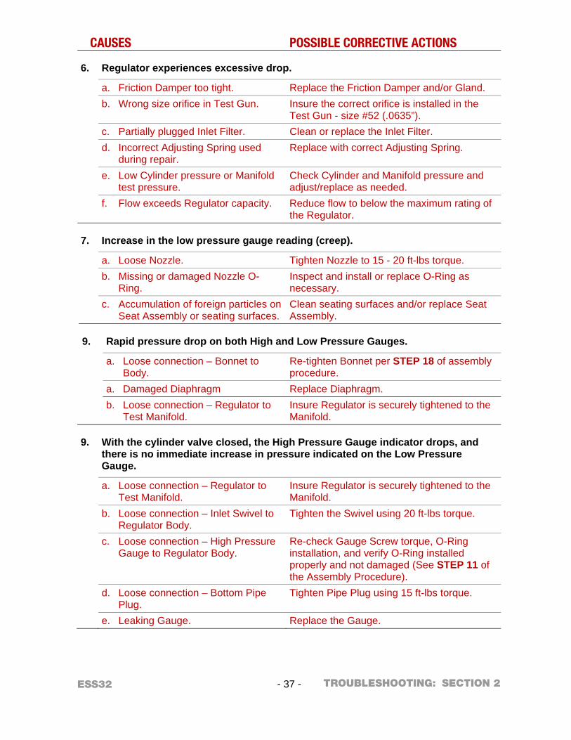
ESS32 - 37 - SECTION 2
CAUSES POSSIBLE CORRECTIVE ACTIONS
6. Regulator experiences excessive drop.
a. Friction Damper too tight. Replace the Friction Damper and/or Gland. b. Wrong size orifice in Test Gun. Insure the correct orifice is installed in the
Test Gun - size #52 (.0635”). c. Partially plugged Inlet Filter. Clean or replace the Inlet Filter. d. Incorrect Adjusting Spring used
during repair. Replace with correct Adjusting Spring.
e. Low Cylinder pressure or Manifold test pressure.
Check Cylinder and Manifold pressure and adjust/replace as needed.
f. Flow exceeds Regulator capacity. Reduce flow to below the maximum rating of the Regulator.
7. Increase in the low pressure gauge reading (creep).
a. Loose Nozzle. Tighten Nozzle to 15 - 20 ft-lbs torque. b. Missing or damaged Nozzle O-
Ring. Inspect and install or replace O-Ring as necessary.
c. Accumulation of foreign particles on Seat Assembly or seating surfaces.
Clean seating surfaces and/or replace Seat Assembly.
9. Rapid pressure drop on both High and Low Pressure Gauges.
a. Loose connection – Bonnet to Body.
Re-tighten Bonnet per STEP 18 of assembly procedure.
a. Damaged Diaphragm Replace Diaphragm. b. Loose connection – Regulator to
Test Manifold. Insure Regulator is securely tightened to the Manifold.
9. With the cylinder valve closed, the High Pressure Gauge indicator drops, and there is no immediate increase in pressure indicated on the Low Pressure Gauge.
a. Loose connection – Regulator to Test Manifold.
Insure Regulator is securely tightened to the Manifold.
b. Loose connection – Inlet Swivel to Regulator Body.
Tighten the Swivel using 20 ft-lbs torque.
c. Loose connection – High Pressure Gauge to Regulator Body.
Re-check Gauge Screw torque, O-Ring installation, and verify O-Ring installed properly and not damaged (See STEP 11 of the Assembly Procedure).
d. Loose connection – Bottom Pipe Plug.
Tighten Pipe Plug using 15 ft-lbs torque.
e. Leaking Gauge. Replace the Gauge.
TROUBLESHOOTING:
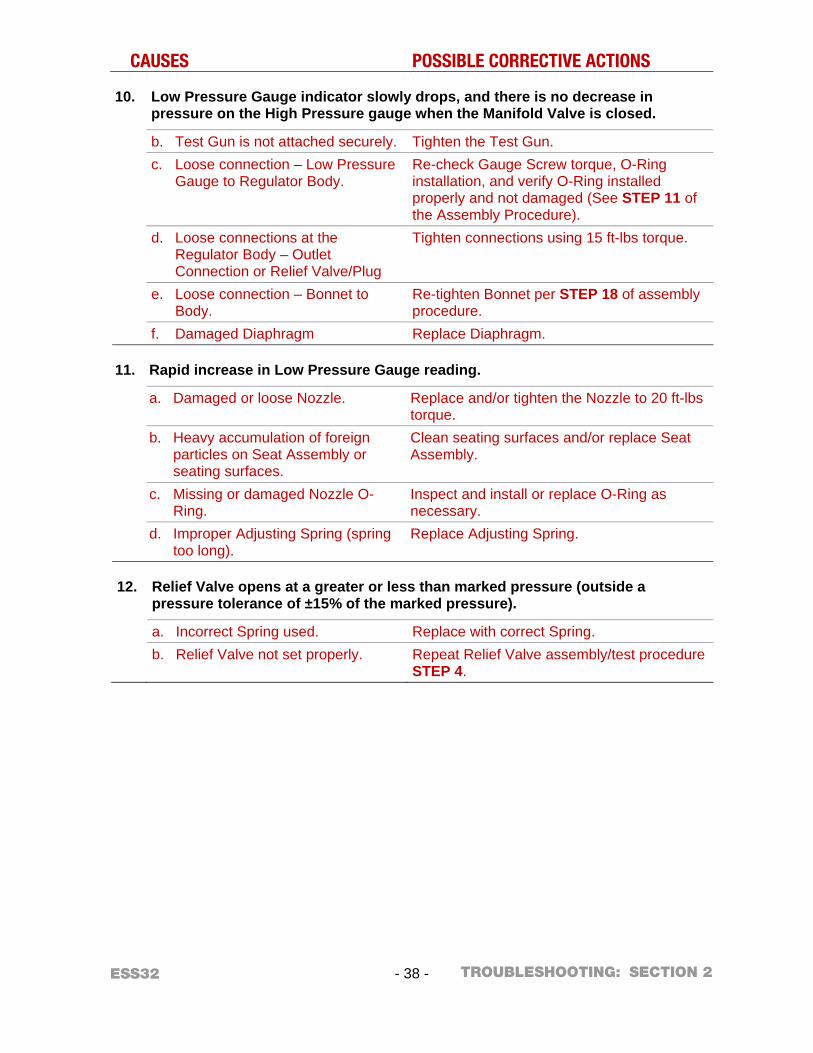
ESS32 - 38 - SECTION 2
CAUSES POSSIBLE CORRECTIVE ACTIONS
10. Low Pressure Gauge indicator slowly drops, and there is no decrease in pressure on the High Pressure gauge when the Manifold Valve is closed.
b. Test Gun is not attached securely. Tighten the Test Gun. c. Loose connection – Low Pressure
Gauge to Regulator Body. Re-check Gauge Screw torque, O-Ring installation, and verify O-Ring installed properly and not damaged (See STEP 11 of the Assembly Procedure).
d. Loose connections at the Regulator Body – Outlet Connection or Relief Valve/Plug
Tighten connections using 15 ft-lbs torque.
e. Loose connection – Bonnet to Body.
Re-tighten Bonnet per STEP 18 of assembly procedure.
f. Damaged Diaphragm Replace Diaphragm.
11. Rapid increase in Low Pressure Gauge reading.
a. Damaged or loose Nozzle. Replace and/or tighten the Nozzle to 20 ft-lbs torque.
b. Heavy accumulation of foreign particles on Seat Assembly or seating surfaces.
Clean seating surfaces and/or replace Seat Assembly.
c. Missing or damaged Nozzle O-Ring.
Inspect and install or replace O-Ring as necessary.
d. Improper Adjusting Spring (spring too long).
Replace Adjusting Spring.
12. Relief Valve opens at a greater or less than marked pressure (outside a pressure tolerance of ±15% of the marked pressure).
a. Incorrect Spring used. Replace with correct Spring. b. Relief Valve not set properly. Repeat Relief Valve assembly/test procedure
STEP 4.
TROUBLESHOOTING:
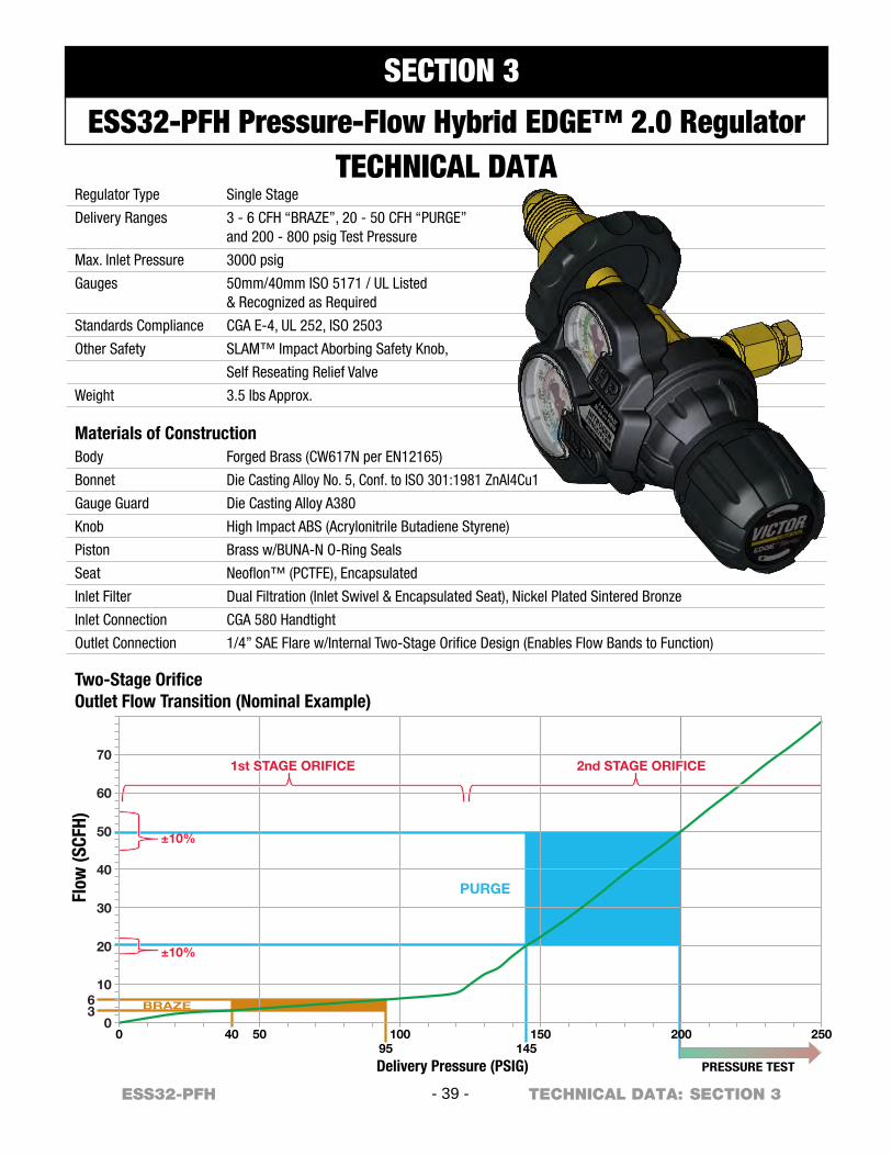
PURGE
BRAZE
±10%
±10%
PRESSURE TEST
40
Delivery Pressure (PSIG)
Flow
(SCF
H)
50 10095 145
150 200 25000
36
10
20
30
40
50
60
70
Two-Stage OrificeOutlet Flow Transition (Nominal Example)
1st STAGE ORIFICE 2nd STAGE ORIFICE
Regulator Type
Delivery Ranges
Max. Inlet Pressure
Gauges
Standards Compliance
Other Safety
Weight
Single Stage
3 - 6 CFH “BRAZE”, 20 - 50 CFH “PURGE”and 200 - 800 psig Test Pressure
3000 psig
50mm/40mm ISO 5171 / UL Listed& Recognized as Required
CGA E-4, UL 252, ISO 2503
SLAM™ Impact Aborbing Safety Knob,
Self Reseating Relief Valve
3.5 lbs Approx.
Materials of ConstructionBody
Bonnet
Gauge Guard
Knob
Piston
Seat
Inlet Filter
Inlet Connection
Outlet Connection
Forged Brass (CW617N per EN12165)
Die Casting Alloy No. 5, Conf. to ISO 301:1981 ZnAl4Cu1
Die Casting Alloy A380
High Impact ABS (Acrylonitrile Butadiene Styrene)
Brass w/BUNA-N O-Ring Seals
Neoflon™ (PCTFE), Encapsulated
Dual Filtration (Inlet Swivel & Encapsulated Seat), Nickel Plated Sintered Bronze
CGA 580 Handtight
1/4” SAE Flare w/Internal Two-Stage Orifice Design (Enables Flow Bands to Function)
- 39 -ESS32-PFH SECTION 3TECHNICAL DATA:
SECTION 3
ESS32-PFH Pressure-Flow Hybrid EDGE™ 2.0 RegulatorTECHNICAL DATA
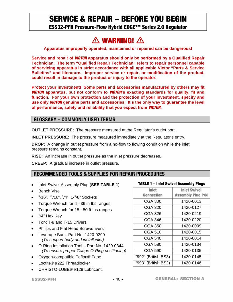
ESS32-PFH - 40 - SECTION 3 GENERAL:
SERVICE & REPAIR – BEFORE YOU BEGIN ESS32-PFH Pressure-Flow Hybrid EDGE™ Series 2.0 Regulator
m WARNING! m Apparatus improperly operated, maintained or repaired can be dangerous!
Service and repair of VICTOR apparatus should only be performed by a Qualified Repair Technician. The term “Qualified Repair Technician” refers to repair personnel capable of servicing apparatus in strict accordance with all applicable Victor “Parts & Service Bulletins” and literature. Improper service or repair, or modification of the product, could result in damage to the product or injury to the operator. Protect your investment! Some parts and accessories manufactured by others may fit VICTOR apparatus, but not conform to VICTOR’s exacting standards for quality, fit and function. For your own protection and the protection of your investment, specify and use only VICTOR genuine parts and accessories. It’s the only way to guarantee the level of performance, safety and reliability that you expect from VICTOR.
GLOSSARY – COMMONLY USED TERMS
OUTLET PRESSURE: The pressure measured at the Regulator’s outlet port.
INLET PRESSURE: The pressure measured immediately at the Regulator’s entry.
DROP: A change in outlet pressure from a no-flow to flowing condition while the inlet pressure remains constant.
RISE: An increase in outlet pressure as the inlet pressure decreases.
CREEP: A gradual increase in outlet pressure. RECOMMENDED TOOLS & SUPPLIES FOR REPAIR PROCEDURES
Inlet Swivel Assembly Plug (SEE TABLE 1) Bench Vise 9/16”, 11/16”, 3/4”, 1-5/8” Sockets Torque Wrench for 4 - 36 in-lbs ranges Torque Wrench for 15 - 50 ft-lbs ranges 1/4” Hex Key Torx T-8 and T-15 Drivers Philips and Flat Head Screwdrivers Leverage Bar – Part No. 1420-0299
(To support body and install inlet)
O-Ring Installation Tool – Part No. 1420-0344 (To ensure proper Gauge O-Ring positioning)
Oxygen-compatible Teflon® Tape Loctite® #222 Threadlocker CHRISTO-LUBE® #129 Lubricant.
TABLE 1 – Inlet Swivel Assembly Plugs
Inlet Connection
Inlet Swivel Assembly Plug P/N
CGA 300 1420-0013 CGA 320 1420-0127 CGA 326 1420-0219 CGA 346 1420-0220 CGA 350 1420-0009 CGA 510 1420-0015 CGA 540 1420-0014 CGA 580 1420-0134 CGA 590 1420-0135
“992” (British BS3) 1420-0145 “993” (British BS2) 1420-0146
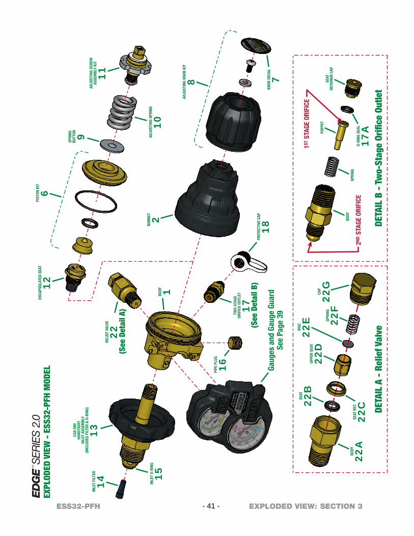
INLE
T FI
LTER
14
BODY 1
RELI
EF V
ALVE
22(S
ee D
etai
l A)
EXPL
ODED
VIE
W -
ESS
32-P
FH M
ODEL
BONN
ET 2
Gaug
es a
nd G
auge
Gua
rdSe
e Pa
ge 3
9
PIST
ON K
IT
6
CGA
580
HAND
TIGH
TIN
LET
ASSE
MBL
Y(IN
CLUD
ES F
ILTE
R &
O-R
ING)
13
PIPE
PLU
G
16TW
O-ST
AGE
ORIF
ICE
OUTL
ET
17
ENCA
PSUL
ATED
SEA
T
12
ADJU
STIN
G SP
RING
10
ADJU
STIN
G SC
REW
ASSE
MBL
Y KI
T
11
ADJU
STIN
G KN
OB K
IT
8
KNOB
DEC
AL
7
SPRI
NGBU
TTON 9
PROT
ECTI
VE C
AP
18(S
ee D
etai
l B)
INLE
T O-
RING
15
BODY
22A
SEAT
RET
.
22C
DISC
22E
SEAT
22B
UPPE
R SE
AT
22D
SPRI
NG
22F
CAP
22G
DETA
IL A
- R
elie
f Val
veDE
TAIL
B -
Tw
o-St
age
Orifi
ce O
utle
t
BODY
SPRI
NG
POPP
ETSE
ATRE
TAIN
ER C
AP
1ST S
TAGE
ORI
FICE
2ND
STAG
E OR
IFIC
EO-
RING
SEA
L
17A
- 41 -ESS32-PFH SECTION 3EXPLODED VIEW:
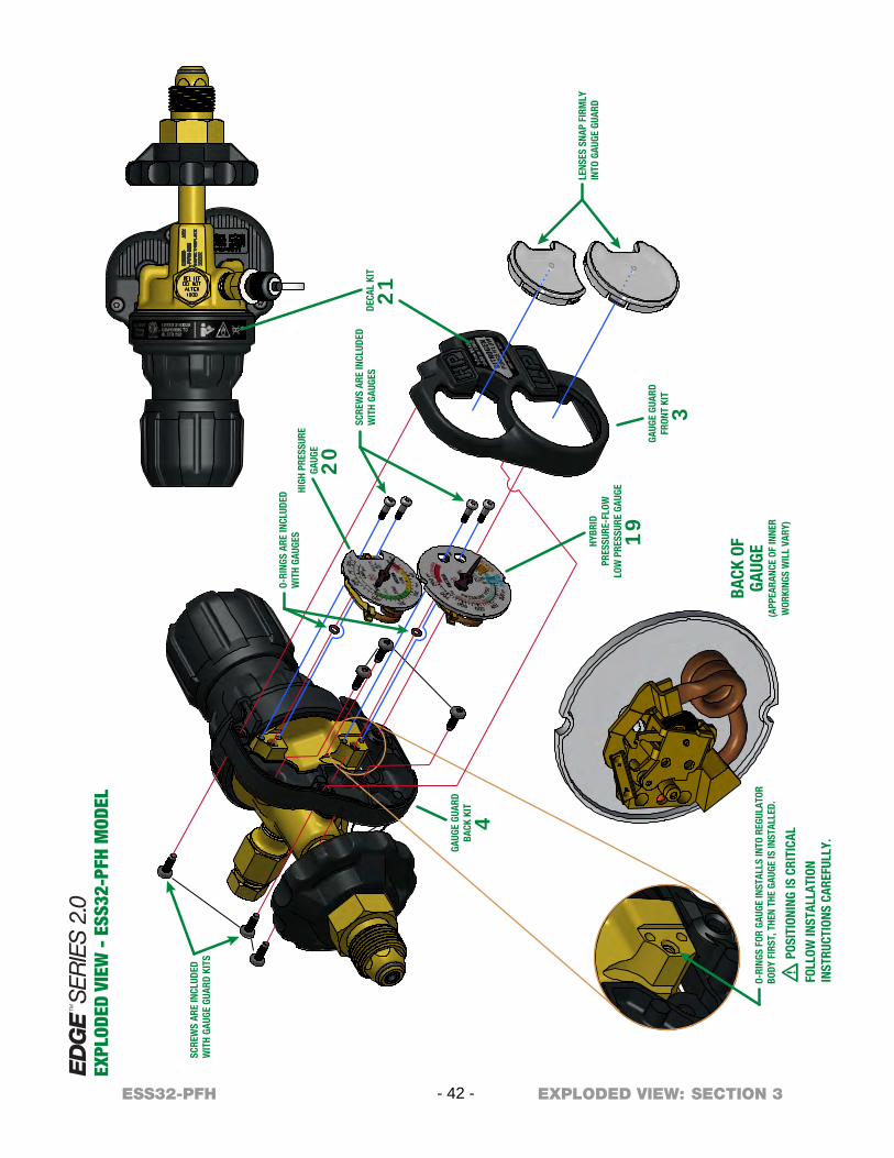
BACK
OF
GAUG
E(A
PPEA
RANC
E OF
INNE
RW
ORKI
NGS
WIL
L VA
RY)
m P
OSIT
IONI
NG IS
CRI
TICA
L
FOLL
OW IN
STAL
LATI
ONIN
STRU
CTIO
NS C
AREF
ULLY
.
LENS
ES S
NAP
FIRM
LYIN
TO G
AUGE
GUA
RD
SCRE
WS
ARE
INCL
UDED
WIT
H GA
UGES
O-RI
NGS
ARE
INCL
UDED
WIT
H GA
UGES
DECA
L KI
T
21
HIGH
PRE
SSUR
EGA
UGE
20
HYBR
IDPR
ESSU
RE-F
LOW
LOW
PRE
SSUR
E GA
UGE
19GA
UGE
GUAR
DFR
ONT
KIT
3
SCRE
WS
ARE
INCL
UDED
WIT
H GA
UGE
GUAR
D KI
TS
GAUG
E GU
ARD
BACK
KIT
4
O-RI
NGS
FOR
GAUG
E IN
STAL
LS IN
TO R
EGUL
ATOR
BODY
FIR
ST, T
HEN
THE
GAUG
E IS
INST
ALLE
D.
EXPL
ODED
VIE
W -
ESS
32-P
FH M
ODEL
- 42 -ESS32-PFH SECTION 3EXPLODED VIEW:
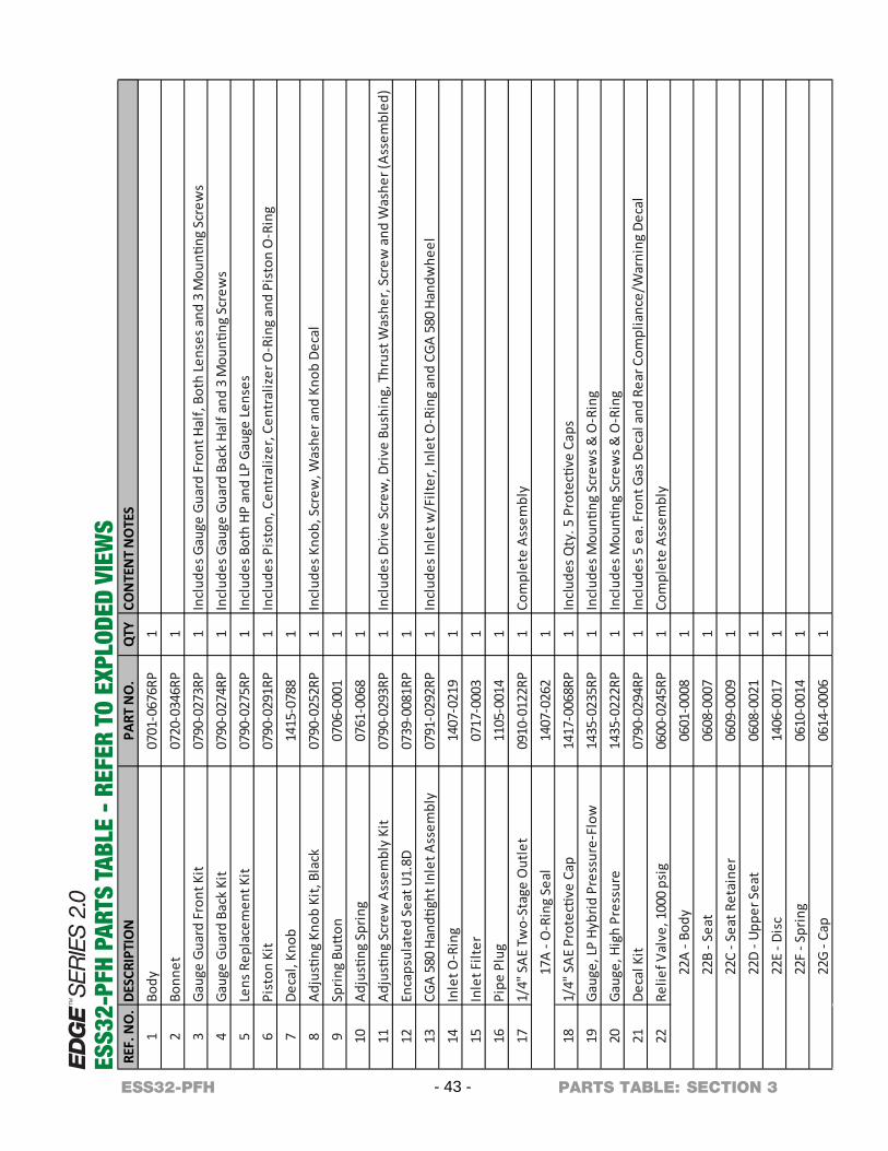
REF.
NO
.DE
SCRI
PTIO
NPA
RT N
O.
QTY
CON
TEN
T N
OTE
S1
Body
0701
-067
6RP
12
Bonn
et07
20-0
346R
P1
3Ga
uge
Guar
d Fr
ont K
it07
90-0
273R
P1
Incl
udes
Gau
ge G
uard
Fro
nt H
alf,
Both
Lens
es a
nd 3
Mou
nting
Scr
ews
4Ga
uge
Guar
d Ba
ck K
it07
90-0
274R
P1
Incl
udes
Gau
ge G
uard
Bac
k Ha
lf an
d 3
Mou
nting
Scr
ews
5Le
ns R
epla
cem
ent K
it07
90-0
275R
P1
Incl
udes
Bot
h HP
and
LP G
auge
Lens
es6
Pist
on K
it07
90-0
291R
P1
Incl
udes
Pis
ton,
Cen
tral
izer
, Cen
tral
izer
O-R
ing
and
Pist
on O
-Rin
g7
Deca
l, Kn
ob14
15-0
788
18
Adju
sting
Kno
b Ki
t, Bl
ack
0790
-025
2RP
1In
clud
es K
nob,
Scr
ew, W
ashe
r and
Kno
b De
cal
9Sp
ring
Butt
on07
06-0
001
110
Adju
sting
Spr
ing
0761
-006
81
11Ad
justi
ng S
crew
Ass
embl
y Ki
t 07
90-0
293R
P1
Incl
udes
Driv
e Sc
rew
, Driv
e Bu
shin
g, T
hrus
t Was
her,
Scre
w a
nd W
ashe
r (As
sem
bled
)12
Enca
psul
ated
Sea
t U1.
8D07
39-0
081R
P1
13C G
A 58
0 Ha
ndtig
ht In
let A
ssem
bly
0791
-029
2RP
1In
clud
es In
let w
/Filt
er, I
nlet
O-R
ing
and
CGA
580
Hand
whe
el14
Inle
t O-R
ing
1407
-021
91
15In
let F
ilter
0717
-000
31
16Pi
pe P
lug
1105
-001
41
171/
4" S
AE T
wo-
Stag
e O
utle
t09
10-0
122R
P1
Com
plet
e As
sem
bly
17A
- O-R
ing
Seal
1407
-026
21
181/
4" S
AE P
rote
ctive
Cap
1417
-006
8RP
119
Gaug
e, LP
Hyb
rid P
ress
ure-
Flow
1435
-023
5RP
1In
clud
es M
ounti
ng S
crew
s & O
-Rin
g20
Gaug
e, H
igh
Pres
sure
1435
-022
2RP
1In
clud
es M
ounti
ng S
crew
s & O
-Rin
g21
Deca
l Kit
0790
-029
4RP
1In
clud
es 5
ea.
Fro
nt G
as D
ecal
and
Rea
r Com
plia
nce/
War
ning
Dec
al22
Relie
f Val
ve, 1
000
psig
0600
-024
5RP
1Co
mpl
ete
Asse
mbl
y22
A - B
ody
0601
-000
81
22B
- Sea
t06
08-0
007
122
C - S
eat R
etai
ner
0609
-000
91
22D
- Upp
er S
eat
0608
-002
11
22E
- Dis
c14
06-0
017
122
F - S
prin
g06
10-0
014
122
G - C
ap06
14-0
006
1
Incl
udes
Qty
. 5 P
rote
ctive
Cap
s
ESS3
2-PF
H PA
RTS
TABL
E -
REFE
R TO
EXP
LODE
D VI
EWS
- 43 -ESS32-PFH SECTION 3PARTS TABLE:
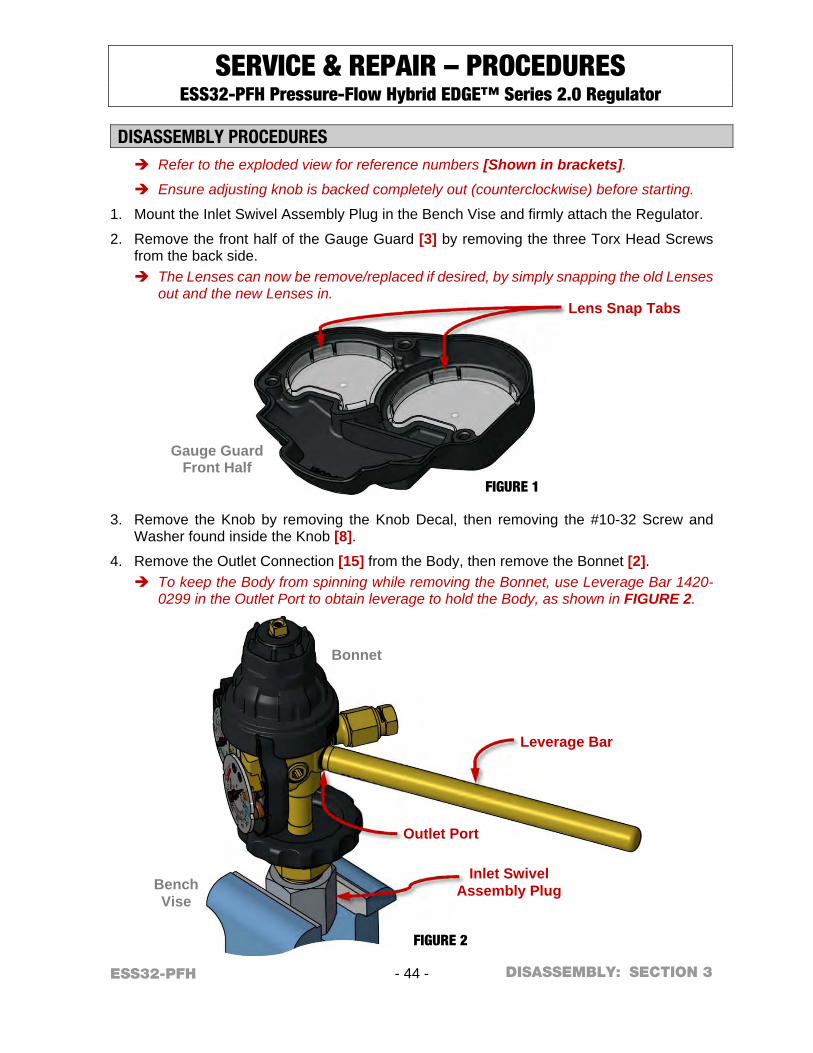
ESS32-PFH - 44 - SECTION 3
SERVICE & REPAIR – PROCEDURES ESS32-PFH Pressure-Flow Hybrid EDGE™ Series 2.0 Regulator
DISASSEMBLY PROCEDURES Refer to the exploded view for reference numbers [Shown in brackets].
Ensure adjusting knob is backed completely out (counterclockwise) before starting.
1. Mount the Inlet Swivel Assembly Plug in the Bench Vise and firmly attach the Regulator.
2. Remove the front half of the Gauge Guard [3] by removing the three Torx Head Screws from the back side. The Lenses can now be remove/replaced if desired, by simply snapping the old Lenses
out and the new Lenses in.
3. Remove the Knob by removing the Knob Decal, then removing the #10-32 Screw and Washer found inside the Knob [8].
4. Remove the Outlet Connection [15] from the Body, then remove the Bonnet [2]. To keep the Body from spinning while removing the Bonnet, use Leverage Bar 1420-
0299 in the Outlet Port to obtain leverage to hold the Body, as shown in FIGURE 2.
Bench Vise
Bonnet
FIGURE 2
Gauge Guard Front Half
FIGURE 1
DISASSEMBLY:
Leverage Bar
Inlet Swivel Assembly Plug
Outlet Port
Lens Snap Tabs
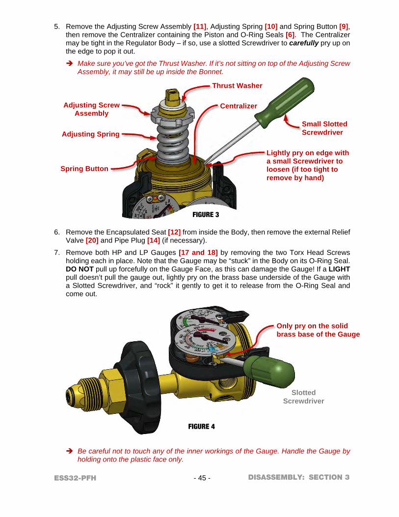
ESS32-PFH - 45 - SECTION 3
5. Remove the Adjusting Screw Assembly [11], Adjusting Spring [10] and Spring Button [9], then remove the Centralizer containing the Piston and O-Ring Seals [6]. The Centralizer may be tight in the Regulator Body – if so, use a slotted Screwdriver to carefully pry up on the edge to pop it out.
Make sure you’ve got the Thrust Washer. If it’s not sitting on top of the Adjusting Screw Assembly, it may still be up inside the Bonnet.
6. Remove the Encapsulated Seat [12] from inside the Body, then remove the external Relief Valve [20] and Pipe Plug [14] (if necessary).
7. Remove both HP and LP Gauges [17 and 18] by removing the two Torx Head Screws holding each in place. Note that the Gauge may be “stuck” in the Body on its O-Ring Seal. DO NOT pull up forcefully on the Gauge Face, as this can damage the Gauge! If a LIGHT pull doesn’t pull the gauge out, lightly pry on the brass base underside of the Gauge with a Slotted Screwdriver, and “rock” it gently to get it to release from the O-Ring Seal and come out.
Be careful not to touch any of the inner workings of the Gauge. Handle the Gauge by holding onto the plastic face only.
Slotted Screwdriver
FIGURE 4
FIGURE 3
DISASSEMBLY:
Only pry on the solid brass base of the Gauge
Lightly pry on edge with a small Screwdriver to loosen (if too tight to remove by hand)
Centralizer Adjusting Screw Assembly
Spring Button
Thrust Washer
Adjusting Spring
Small Slotted Screwdriver
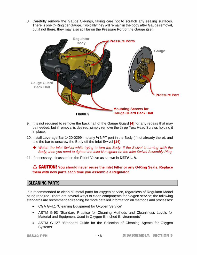
ESS32-PFH - 46 - SECTION 3
8. Carefully remove the Gauge O-Rings, taking care not to scratch any sealing surfaces. There is one O-Ring per Gauge. Typically they will remain in the body after Gauge removal, but if not there, they may also still be on the Pressure Port of the Gauge itself.
9. It is not required to remove the back half of the Gauge Guard [4] for any repairs that may be needed, but if removal is desired, simply remove the three Torx Head Screws holding it in place.
10. Install Leverage Bar 1420-0299 into any ¼ NPT port in the Body (if not already there), and use the bar to unscrew the Body off the Inlet Swivel [14].
Watch the Inlet Swivel while trying to turn the Body. If the Swivel is turning with the Body, then you need to tighten the Inlet Nut tighter on the Inlet Swivel Assembly Plug.
11. If necessary, disassemble the Relief Valve as shown in DETAIL A.
m CAUTION! You should never reuse the Inlet Filter or any O-Ring Seals. Replace them with new parts each time you assemble a Regulator.
CLEANING PARTS It is recommended to clean all metal parts for oxygen service, regardless of Regulator Model being repaired. There are several ways to clean components for oxygen service; the following standards are recommended reading for more detailed information on methods and processes:
CGA G-4.1 “Cleaning Equipment for Oxygen Service”
ASTM G-93 “Standard Practice for Cleaning Methods and Cleanliness Levels for Material and Equipment Used in Oxygen-Enriched Environments”
ASTM G-127 “Standard Guide for the Selection of Cleaning Agents for Oxygen Systems”
Gauge
FIGURE 5
Regulator Body
Gauge Guard Back Half
DISASSEMBLY:
Pressure Ports
Pressure Port
Mounting Screws for Gauge Guard Back Half
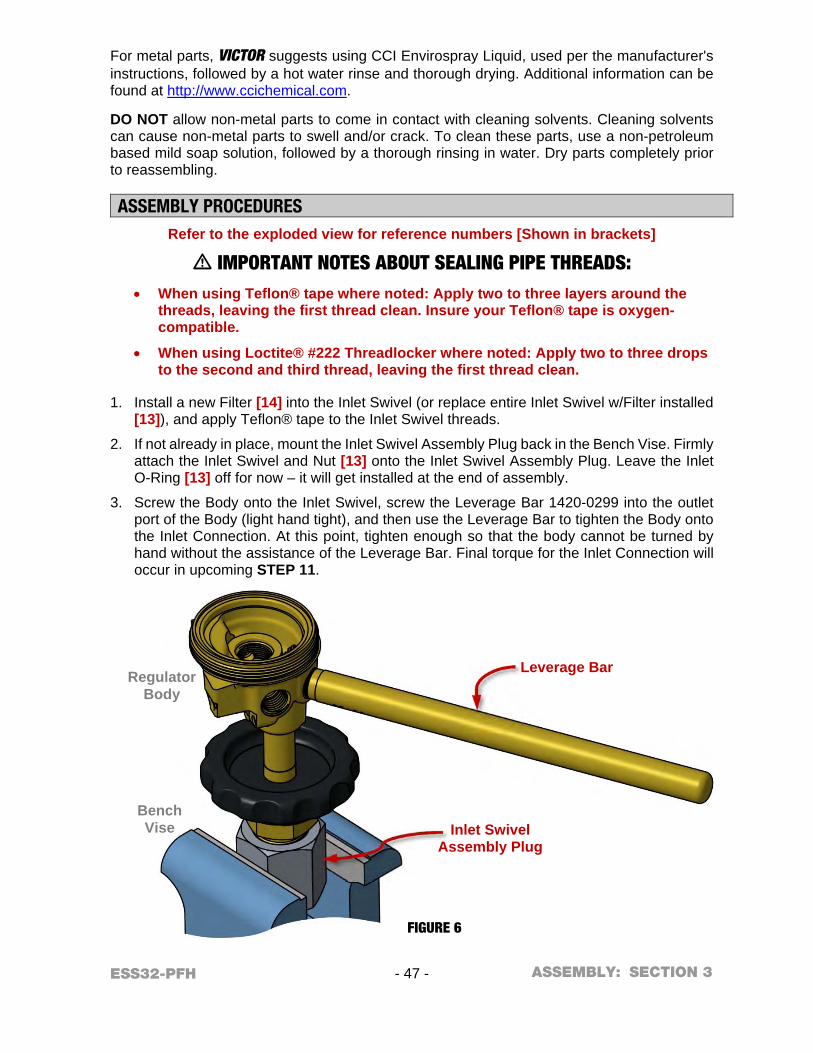
ESS32-PFH - 47 - SECTION 3
For metal parts, VICTOR suggests using CCI Envirospray Liquid, used per the manufacturer's instructions, followed by a hot water rinse and thorough drying. Additional information can be found at http://www.ccichemical.com.
DO NOT allow non-metal parts to come in contact with cleaning solvents. Cleaning solvents can cause non-metal parts to swell and/or crack. To clean these parts, use a non-petroleum based mild soap solution, followed by a thorough rinsing in water. Dry parts completely prior to reassembling.
ASSEMBLY PROCEDURES Refer to the exploded view for reference numbers [Shown in brackets]
m IMPORTANT NOTES ABOUT SEALING PIPE THREADS: When using Teflon® tape where noted: Apply two to three layers around the
threads, leaving the first thread clean. Insure your Teflon® tape is oxygen-compatible.
When using Loctite® #222 Threadlocker where noted: Apply two to three drops to the second and third thread, leaving the first thread clean.
1. Install a new Filter [14] into the Inlet Swivel (or replace entire Inlet Swivel w/Filter installed [13]), and apply Teflon® tape to the Inlet Swivel threads.
2. If not already in place, mount the Inlet Swivel Assembly Plug back in the Bench Vise. Firmly attach the Inlet Swivel and Nut [13] onto the Inlet Swivel Assembly Plug. Leave the Inlet O-Ring [13] off for now – it will get installed at the end of assembly.
3. Screw the Body onto the Inlet Swivel, screw the Leverage Bar 1420-0299 into the outlet port of the Body (light hand tight), and then use the Leverage Bar to tighten the Body onto the Inlet Connection. At this point, tighten enough so that the body cannot be turned by hand without the assistance of the Leverage Bar. Final torque for the Inlet Connection will occur in upcoming STEP 11.
Bench Vise
Regulator Body
FIGURE 6
ASSEMBLY:
Leverage Bar
Inlet Swivel Assembly Plug
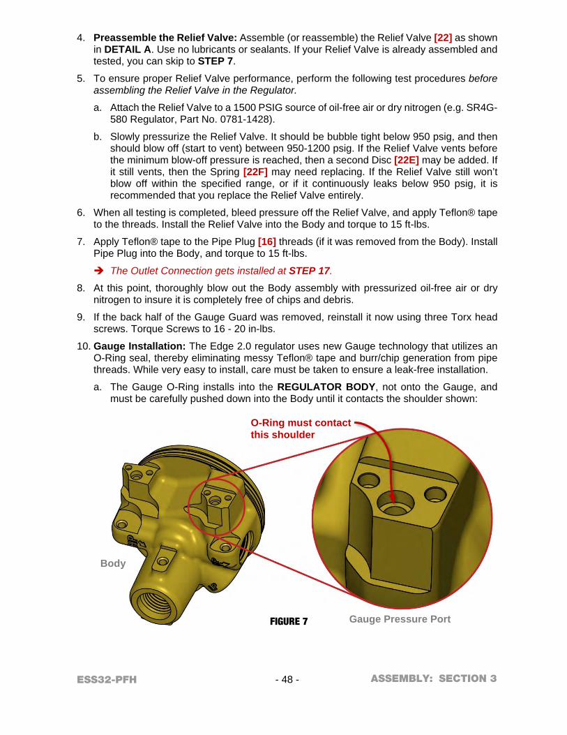
ESS32-PFH - 48 - SECTION 3
4. Preassemble the Relief Valve: Assemble (or reassemble) the Relief Valve [22] as shown in DETAIL A. Use no lubricants or sealants. If your Relief Valve is already assembled and tested, you can skip to STEP 7.
5. To ensure proper Relief Valve performance, perform the following test procedures before assembling the Relief Valve in the Regulator.
a. Attach the Relief Valve to a 1500 PSIG source of oil-free air or dry nitrogen (e.g. SR4G-580 Regulator, Part No. 0781-1428).
b. Slowly pressurize the Relief Valve. It should be bubble tight below 950 psig, and then should blow off (start to vent) between 950-1200 psig. If the Relief Valve vents before the minimum blow-off pressure is reached, then a second Disc [22E] may be added. If it still vents, then the Spring [22F] may need replacing. If the Relief Valve still won’t blow off within the specified range, or if it continuously leaks below 950 psig, it is recommended that you replace the Relief Valve entirely.
6. When all testing is completed, bleed pressure off the Relief Valve, and apply Teflon® tape to the threads. Install the Relief Valve into the Body and torque to 15 ft-lbs.
7. Apply Teflon® tape to the Pipe Plug [16] threads (if it was removed from the Body). Install Pipe Plug into the Body, and torque to 15 ft-lbs.
The Outlet Connection gets installed at STEP 17.
8. At this point, thoroughly blow out the Body assembly with pressurized oil-free air or dry nitrogen to insure it is completely free of chips and debris.
9. If the back half of the Gauge Guard was removed, reinstall it now using three Torx head screws. Torque Screws to 16 - 20 in-lbs.
10. Gauge Installation: The Edge 2.0 regulator uses new Gauge technology that utilizes an O-Ring seal, thereby eliminating messy Teflon® tape and burr/chip generation from pipe threads. While very easy to install, care must be taken to ensure a leak-free installation.
a. The Gauge O-Ring installs into the REGULATOR BODY, not onto the Gauge, and must be carefully pushed down into the Body until it contacts the shoulder shown:
Gauge Pressure Port
Body
FIGURE 7
ASSEMBLY:
O-Ring must contact this shoulder
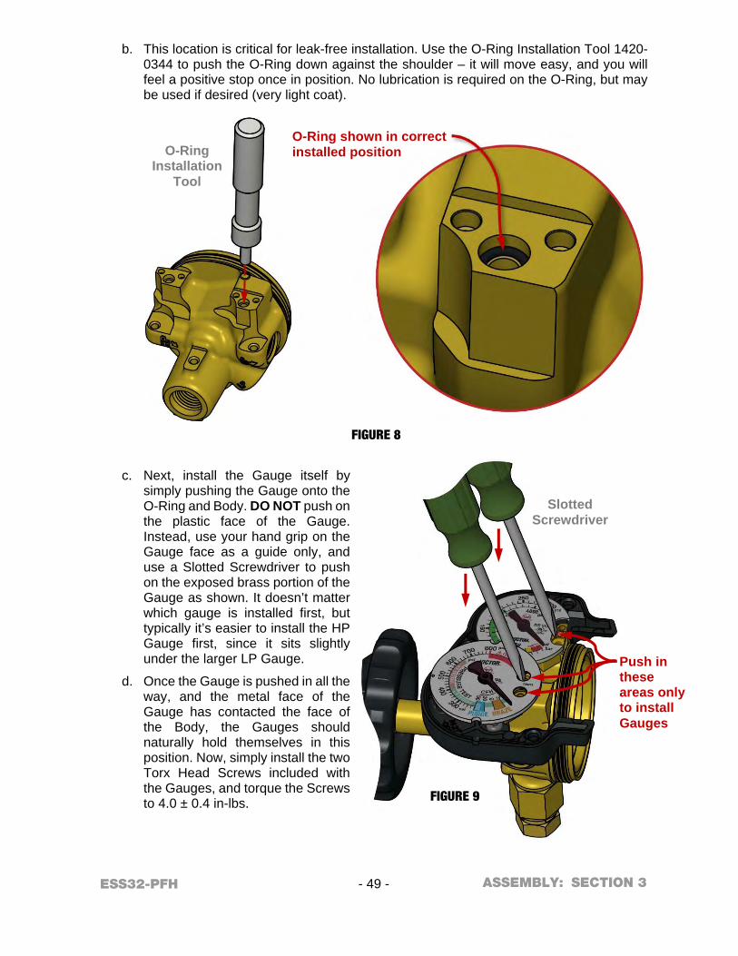
ESS32-PFH - 49 - SECTION 3
b. This location is critical for leak-free installation. Use the O-Ring Installation Tool 1420-0344 to push the O-Ring down against the shoulder – it will move easy, and you will feel a positive stop once in position. No lubrication is required on the O-Ring, but may be used if desired (very light coat).
c. Next, install the Gauge itself by
simply pushing the Gauge onto the O-Ring and Body. DO NOT push on the plastic face of the Gauge. Instead, use your hand grip on the Gauge face as a guide only, and use a Slotted Screwdriver to push on the exposed brass portion of the Gauge as shown. It doesn’t matter which gauge is installed first, but typically it’s easier to install the HP Gauge first, since it sits slightly under the larger LP Gauge.
d. Once the Gauge is pushed in all the way, and the metal face of the Gauge has contacted the face of the Body, the Gauges should naturally hold themselves in this position. Now, simply install the two Torx Head Screws included with the Gauges, and torque the Screws to 4.0 ± 0.4 in-lbs.
O-Ring Installation
Tool
Slotted Screwdriver
FIGURE 8
FIGURE 9
ASSEMBLY:
O-Ring shown in correct installed position
Push in these areas only to install Gauges
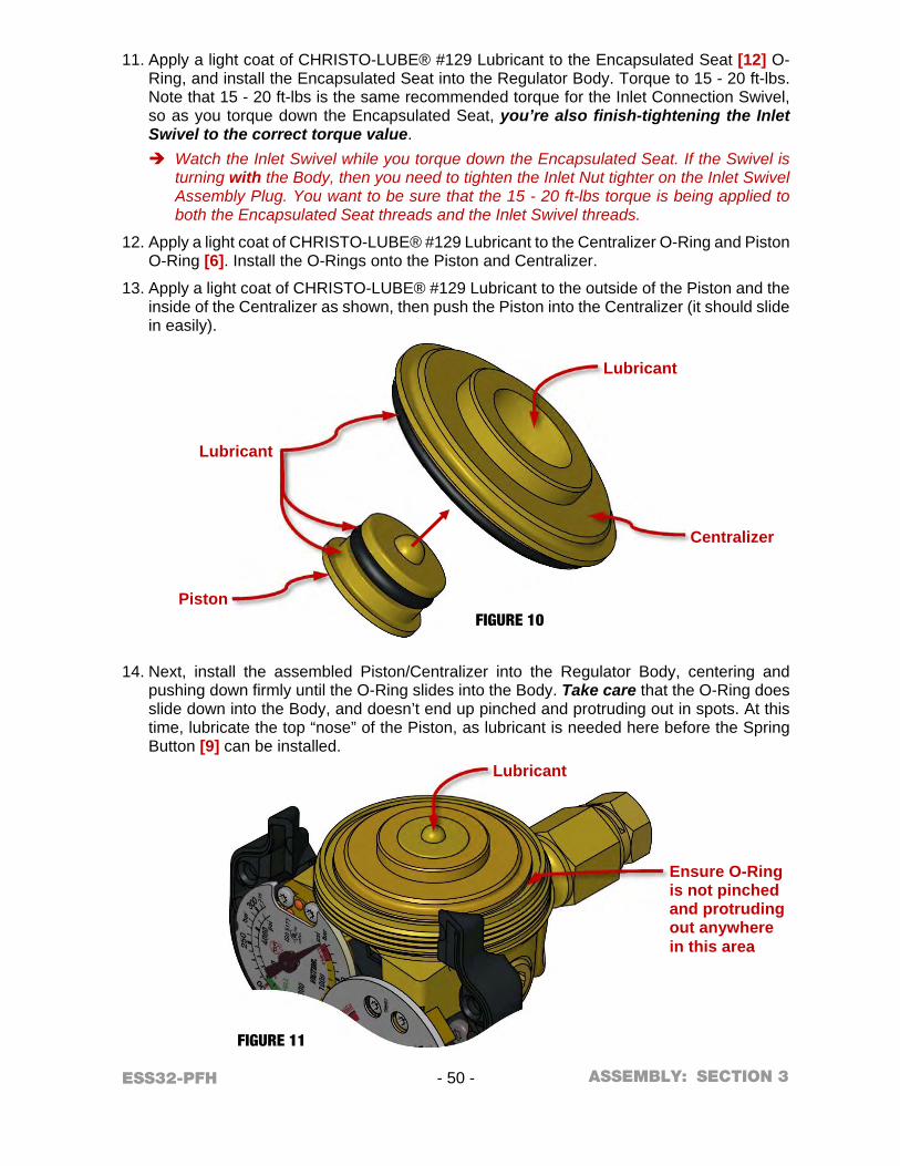
ESS32-PFH - 50 - SECTION 3
11. Apply a light coat of CHRISTO-LUBE® #129 Lubricant to the Encapsulated Seat [12] O-Ring, and install the Encapsulated Seat into the Regulator Body. Torque to 15 - 20 ft-lbs. Note that 15 - 20 ft-lbs is the same recommended torque for the Inlet Connection Swivel, so as you torque down the Encapsulated Seat, you’re also finish-tightening the Inlet Swivel to the correct torque value. Watch the Inlet Swivel while you torque down the Encapsulated Seat. If the Swivel is
turning with the Body, then you need to tighten the Inlet Nut tighter on the Inlet Swivel Assembly Plug. You want to be sure that the 15 - 20 ft-lbs torque is being applied to both the Encapsulated Seat threads and the Inlet Swivel threads.
12. Apply a light coat of CHRISTO-LUBE® #129 Lubricant to the Centralizer O-Ring and Piston O-Ring [6]. Install the O-Rings onto the Piston and Centralizer.
13. Apply a light coat of CHRISTO-LUBE® #129 Lubricant to the outside of the Piston and the inside of the Centralizer as shown, then push the Piston into the Centralizer (it should slide in easily).
14. Next, install the assembled Piston/Centralizer into the Regulator Body, centering and pushing down firmly until the O-Ring slides into the Body. Take care that the O-Ring does slide down into the Body, and doesn’t end up pinched and protruding out in spots. At this time, lubricate the top “nose” of the Piston, as lubricant is needed here before the Spring Button [9] can be installed.
FIGURE 10
FIGURE 11
ASSEMBLY:
Lubricant
Lubricant
Centralizer
Ensure O-Ring is not pinched and protruding out anywhere in this area
Lubricant
Piston
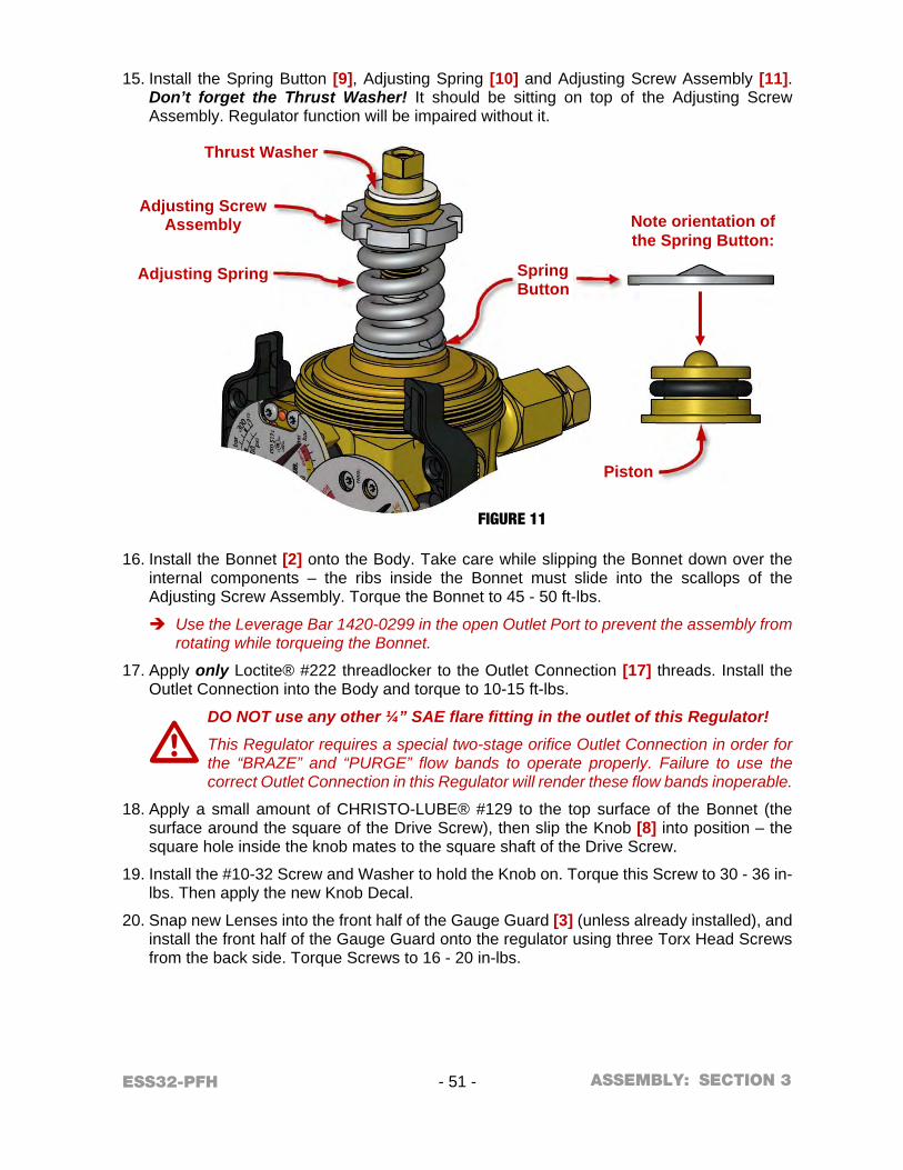
ESS32-PFH - 51 - SECTION 3
15. Install the Spring Button [9], Adjusting Spring [10] and Adjusting Screw Assembly [11].
Don’t forget the Thrust Washer! It should be sitting on top of the Adjusting Screw Assembly. Regulator function will be impaired without it.
16. Install the Bonnet [2] onto the Body. Take care while slipping the Bonnet down over the internal components – the ribs inside the Bonnet must slide into the scallops of the Adjusting Screw Assembly. Torque the Bonnet to 45 - 50 ft-lbs.
Use the Leverage Bar 1420-0299 in the open Outlet Port to prevent the assembly from rotating while torqueing the Bonnet.
17. Apply only Loctite® #222 threadlocker to the Outlet Connection [17] threads. Install the Outlet Connection into the Body and torque to 10-15 ft-lbs.
DO NOT use any other ¼” SAE flare fitting in the outlet of this Regulator!
This Regulator requires a special two-stage orifice Outlet Connection in order for the “BRAZE” and “PURGE” flow bands to operate properly. Failure to use the correct Outlet Connection in this Regulator will render these flow bands inoperable.
18. Apply a small amount of CHRISTO-LUBE® #129 to the top surface of the Bonnet (the surface around the square of the Drive Screw), then slip the Knob [8] into position – the square hole inside the knob mates to the square shaft of the Drive Screw.
19. Install the #10-32 Screw and Washer to hold the Knob on. Torque this Screw to 30 - 36 in-lbs. Then apply the new Knob Decal.
20. Snap new Lenses into the front half of the Gauge Guard [3] (unless already installed), and install the front half of the Gauge Guard onto the regulator using three Torx Head Screws from the back side. Torque Screws to 16 - 20 in-lbs.
FIGURE 11
m
ASSEMBLY:
Note orientation of the Spring Button:
Adjusting Screw Assembly
Spring Button
Thrust Washer
Adjusting Spring
Piston
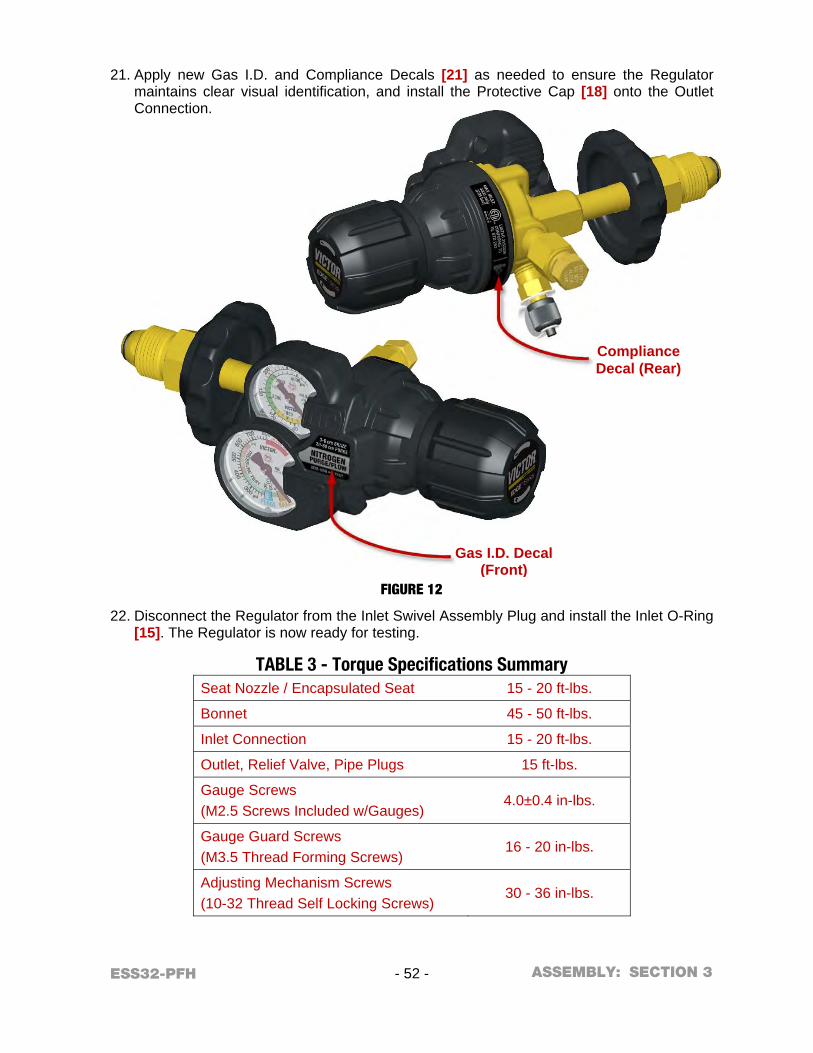
ESS32-PFH - 52 - SECTION 3
21. Apply new Gas I.D. and Compliance Decals [21] as needed to ensure the Regulator
maintains clear visual identification, and install the Protective Cap [18] onto the Outlet Connection.
22. Disconnect the Regulator from the Inlet Swivel Assembly Plug and install the Inlet O-Ring [15]. The Regulator is now ready for testing.
TABLE 3 - Torque Specifications Summary Seat Nozzle / Encapsulated Seat 15 - 20 ft-lbs.
Bonnet 45 - 50 ft-lbs.
Inlet Connection 15 - 20 ft-lbs.
Outlet, Relief Valve, Pipe Plugs 15 ft-lbs.
Gauge Screws (M2.5 Screws Included w/Gauges)
4.0±0.4 in-lbs.
Gauge Guard Screws (M3.5 Thread Forming Screws)
16 - 20 in-lbs.
Adjusting Mechanism Screws (10-32 Thread Self Locking Screws)
30 - 36 in-lbs.
FIGURE 12
ASSEMBLY:
Gas I.D. Decal (Front)
Compliance Decal (Rear)
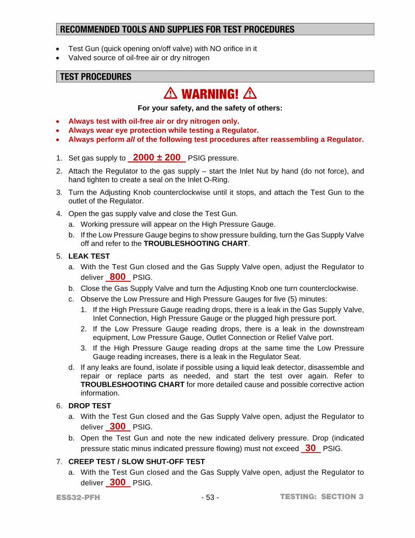
ESS32-PFH - 53 - SECTION 3
RECOMMENDED TOOLS AND SUPPLIES FOR TEST PROCEDURES Test Gun (quick opening on/off valve) with NO orifice in it Valved source of oil-free air or dry nitrogen TEST PROCEDURES
m WARNING! m For your safety, and the safety of others:
Always test with oil-free air or dry nitrogen only. Always wear eye protection while testing a Regulator. Always perform all of the following test procedures after reassembling a Regulator.
1. Set gas supply to 2000 ± 200 PSIG pressure.
2. Attach the Regulator to the gas supply – start the Inlet Nut by hand (do not force), and hand tighten to create a seal on the Inlet O-Ring.
3. Turn the Adjusting Knob counterclockwise until it stops, and attach the Test Gun to the outlet of the Regulator.
4. Open the gas supply valve and close the Test Gun. a. Working pressure will appear on the High Pressure Gauge. b. If the Low Pressure Gauge begins to show pressure building, turn the Gas Supply Valve
off and refer to the TROUBLESHOOTING CHART.
5. LEAK TEST a. With the Test Gun closed and the Gas Supply Valve open, adjust the Regulator to
deliver 800 PSIG. b. Close the Gas Supply Valve and turn the Adjusting Knob one turn counterclockwise. c. Observe the Low Pressure and High Pressure Gauges for five (5) minutes:
1. If the High Pressure Gauge reading drops, there is a leak in the Gas Supply Valve, Inlet Connection, High Pressure Gauge or the plugged high pressure port.
2. If the Low Pressure Gauge reading drops, there is a leak in the downstream equipment, Low Pressure Gauge, Outlet Connection or Relief Valve port.
3. If the High Pressure Gauge reading drops at the same time the Low Pressure Gauge reading increases, there is a leak in the Regulator Seat.
d. If any leaks are found, isolate if possible using a liquid leak detector, disassemble and repair or replace parts as needed, and start the test over again. Refer to TROUBLESHOOTING CHART for more detailed cause and possible corrective action information.
6. DROP TEST a. With the Test Gun closed and the Gas Supply Valve open, adjust the Regulator to
deliver 300 PSIG. b. Open the Test Gun and note the new indicated delivery pressure. Drop (indicated
pressure static minus indicated pressure flowing) must not exceed 30 PSIG.
7. CREEP TEST / SLOW SHUT-OFF TEST a. With the Test Gun closed and the Gas Supply Valve open, adjust the Regulator to
deliver 300 PSIG.
TESTING:
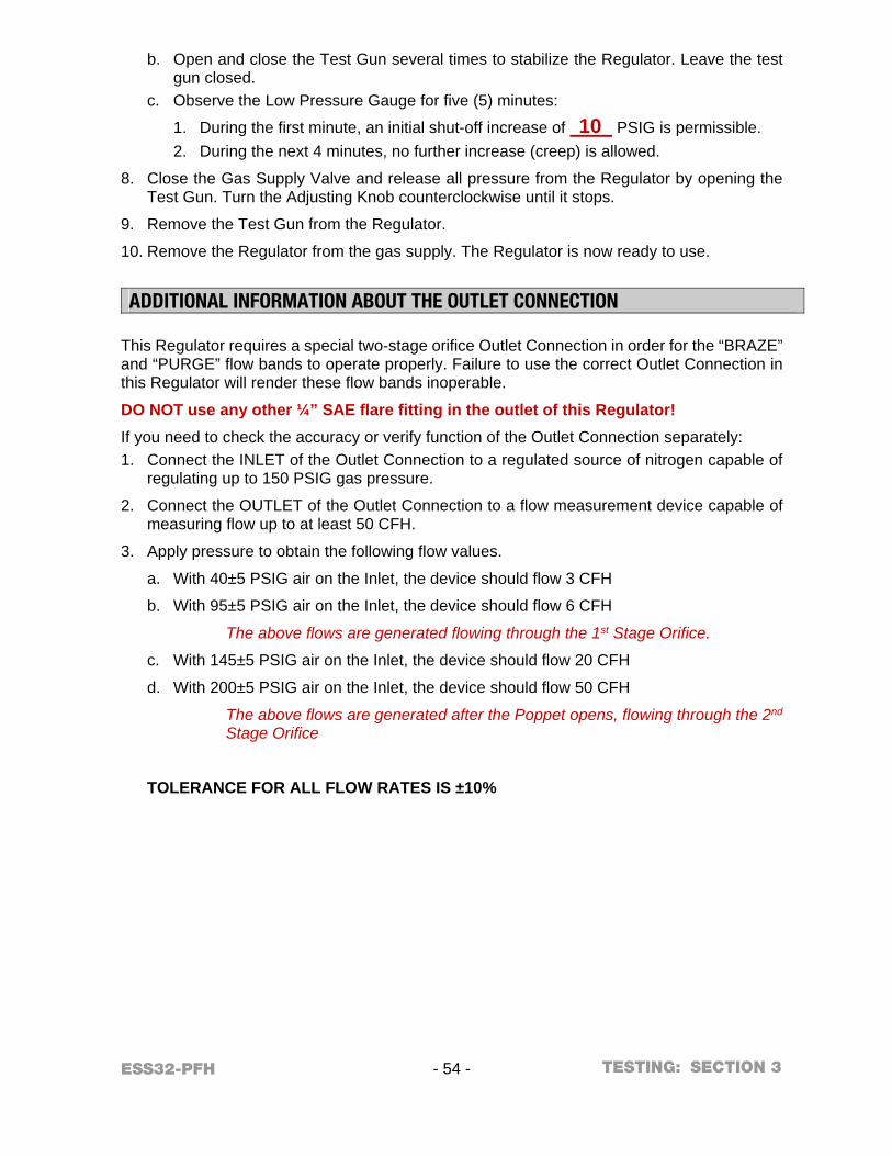
ESS32-PFH - 54 - SECTION 3
b. Open and close the Test Gun several times to stabilize the Regulator. Leave the test gun closed.
c. Observe the Low Pressure Gauge for five (5) minutes:
1. During the first minute, an initial shut-off increase of 10 PSIG is permissible. 2. During the next 4 minutes, no further increase (creep) is allowed.
8. Close the Gas Supply Valve and release all pressure from the Regulator by opening the Test Gun. Turn the Adjusting Knob counterclockwise until it stops.
9. Remove the Test Gun from the Regulator.
10. Remove the Regulator from the gas supply. The Regulator is now ready to use.
ADDITIONAL INFORMATION ABOUT THE OUTLET CONNECTION This Regulator requires a special two-stage orifice Outlet Connection in order for the “BRAZE” and “PURGE” flow bands to operate properly. Failure to use the correct Outlet Connection in this Regulator will render these flow bands inoperable.
DO NOT use any other ¼” SAE flare fitting in the outlet of this Regulator!
If you need to check the accuracy or verify function of the Outlet Connection separately: 1. Connect the INLET of the Outlet Connection to a regulated source of nitrogen capable of
regulating up to 150 PSIG gas pressure.
2. Connect the OUTLET of the Outlet Connection to a flow measurement device capable of measuring flow up to at least 50 CFH.
3. Apply pressure to obtain the following flow values.
a. With 40±5 PSIG air on the Inlet, the device should flow 3 CFH
b. With 95±5 PSIG air on the Inlet, the device should flow 6 CFH
The above flows are generated flowing through the 1st Stage Orifice.
c. With 145±5 PSIG air on the Inlet, the device should flow 20 CFH
d. With 200±5 PSIG air on the Inlet, the device should flow 50 CFH
The above flows are generated after the Poppet opens, flowing through the 2nd Stage Orifice
TOLERANCE FOR ALL FLOW RATES IS ±10%
TESTING:
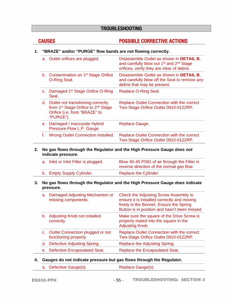
ESS32-PFH - 55 - SECTION 3
TROUBLESHOOTING
CAUSES POSSIBLE CORRECTIVE ACTIONS
1. “BRAZE” and/or “PURGE” flow bands are not flowing correctly.
a. Outlet orifices are plugged. Disassemble Outlet as shown in DETAIL B, and carefully blow out 1st and 2nd Stage orifices, verify they are clear of debris.
b. Contamination on 1st Stage Orifice O-Ring Seal.
Disassemble Outlet as shown in DETAIL B, and carefully blow off the Seat to remove any debris that may be present.
c. Damaged 1st Stage Orifice O-Ring Seal.
Replace O-Ring Seal.
d. Outlet not transitioning correctly from 1st Stage Orifice to 2nd Stage Orifice (i.e. from “BRAZE” to “PURGE”).
Replace Outlet Connection with the correct Two-Stage Orifice Outlet 0910-0122RP.
e. Damaged / inaccurate Hybrid Pressure-Flow L.P. Gauge.
Replace Gauge.
f. Wrong Outlet Connection installed. Replace Outlet Connection with the correct Two-Stage Orifice Outlet 0910-0122RP.
2. No gas flows through the Regulator and the High Pressure Gauge does not indicate pressure.
a. Inlet or Inlet Filter is plugged. Blow 40-45 PSIG of air through the Filter in reverse direction of the normal gas flow.
b. Empty Supply Cylinder. Replace the Cylinder.
3. No gas flows through the Regulator and the High Pressure Gauge does indicate pressure.
a. Damaged Adjusting Mechanism or missing components.
Check the Adjusting Screw Assembly to ensure it is installed correctly and moving freely in the Bonnet. Ensure the Spring Button is in position and hasn’t been missed.
b. Adjusting Knob not installed correctly.
Make sure the square of the Drive Screw is properly mated into the square in the Adjusting Knob.
c. Outlet Connection plugged or not functioning properly.
Replace Outlet Connection with the correct Two-Stage Orifice Outlet 0910-0122RP.
d. Defective Adjusting Spring. Replace the Adjusting Spring. e. Defective Encapsulated Seat. Replace the Encapsulated Seat.
4. Gauges do not indicate pressure but gas flows through the Regulator.
a. Defective Gauge(s). Replace Gauge(s).
TROUBLESHOOTING:
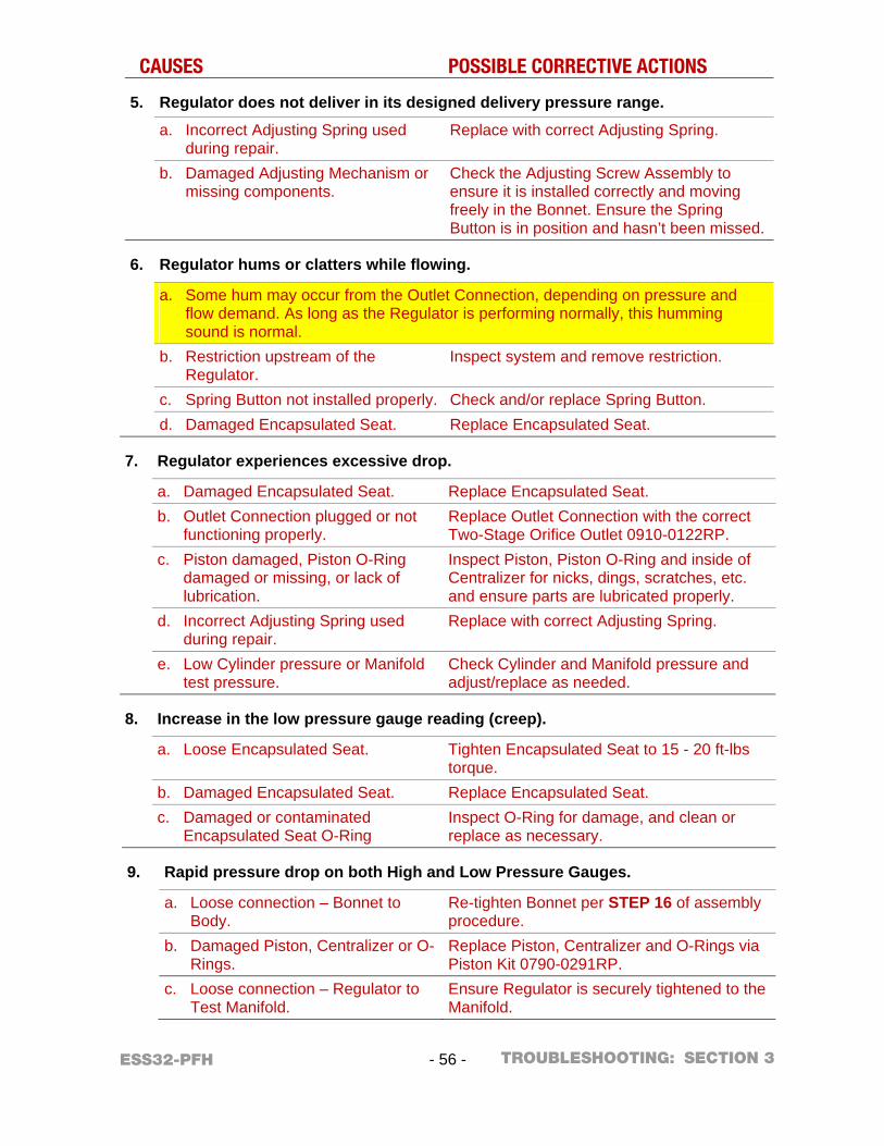
ESS32-PFH - 56 - SECTION 3
CAUSES POSSIBLE CORRECTIVE ACTIONS
5. Regulator does not deliver in its designed delivery pressure range.
a. Incorrect Adjusting Spring used during repair.
Replace with correct Adjusting Spring.
b. Damaged Adjusting Mechanism or missing components.
Check the Adjusting Screw Assembly to ensure it is installed correctly and moving freely in the Bonnet. Ensure the Spring Button is in position and hasn’t been missed.
6. Regulator hums or clatters while flowing.
a. Some hum may occur from the Outlet Connection, depending on pressure and flow demand. As long as the Regulator is performing normally, this humming sound is normal.
b. Restriction upstream of the Regulator.
Inspect system and remove restriction.
c. Spring Button not installed properly. Check and/or replace Spring Button. d. Damaged Encapsulated Seat. Replace Encapsulated Seat.
7. Regulator experiences excessive drop.
a. Damaged Encapsulated Seat. Replace Encapsulated Seat. b. Outlet Connection plugged or not
functioning properly. Replace Outlet Connection with the correct Two-Stage Orifice Outlet 0910-0122RP.
c. Piston damaged, Piston O-Ring damaged or missing, or lack of lubrication.
Inspect Piston, Piston O-Ring and inside of Centralizer for nicks, dings, scratches, etc. and ensure parts are lubricated properly.
d. Incorrect Adjusting Spring used during repair.
Replace with correct Adjusting Spring.
e. Low Cylinder pressure or Manifold test pressure.
Check Cylinder and Manifold pressure and adjust/replace as needed.
8. Increase in the low pressure gauge reading (creep).
a. Loose Encapsulated Seat. Tighten Encapsulated Seat to 15 - 20 ft-lbs torque.
b. Damaged Encapsulated Seat. Replace Encapsulated Seat. c. Damaged or contaminated
Encapsulated Seat O-Ring Inspect O-Ring for damage, and clean or replace as necessary.
9. Rapid pressure drop on both High and Low Pressure Gauges.
a. Loose connection – Bonnet to Body.
Re-tighten Bonnet per STEP 16 of assembly procedure.
b. Damaged Piston, Centralizer or O-Rings.
Replace Piston, Centralizer and O-Rings via Piston Kit 0790-0291RP.
c. Loose connection – Regulator to Test Manifold.
Ensure Regulator is securely tightened to the Manifold.
TROUBLESHOOTING:
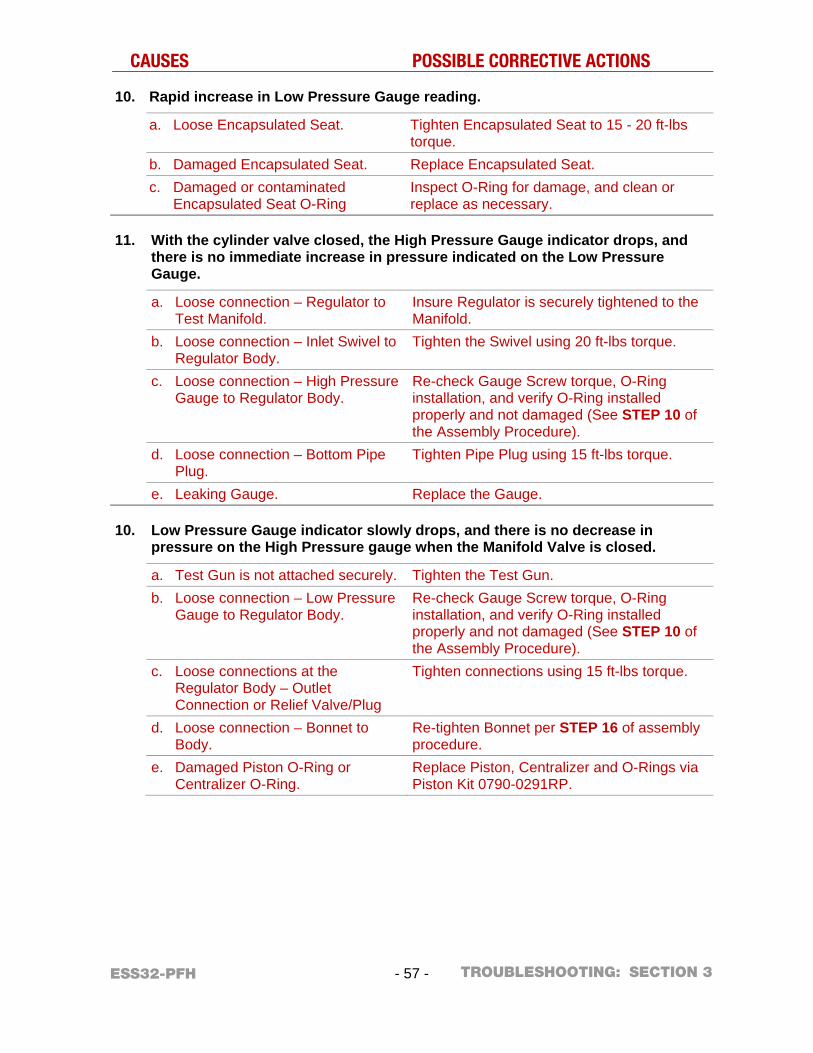
ESS32-PFH - 57 - SECTION 3
CAUSES POSSIBLE CORRECTIVE ACTIONS
10. Rapid increase in Low Pressure Gauge reading.
a. Loose Encapsulated Seat. Tighten Encapsulated Seat to 15 - 20 ft-lbs torque.
b. Damaged Encapsulated Seat. Replace Encapsulated Seat. c. Damaged or contaminated
Encapsulated Seat O-Ring Inspect O-Ring for damage, and clean or replace as necessary.
11. With the cylinder valve closed, the High Pressure Gauge indicator drops, and there is no immediate increase in pressure indicated on the Low Pressure Gauge.
a. Loose connection – Regulator to Test Manifold.
Insure Regulator is securely tightened to the Manifold.
b. Loose connection – Inlet Swivel to Regulator Body.
Tighten the Swivel using 20 ft-lbs torque.
c. Loose connection – High Pressure Gauge to Regulator Body.
Re-check Gauge Screw torque, O-Ring installation, and verify O-Ring installed properly and not damaged (See STEP 10 of the Assembly Procedure).
d. Loose connection – Bottom Pipe Plug.
Tighten Pipe Plug using 15 ft-lbs torque.
e. Leaking Gauge. Replace the Gauge.
10. Low Pressure Gauge indicator slowly drops, and there is no decrease in pressure on the High Pressure gauge when the Manifold Valve is closed.
a. Test Gun is not attached securely. Tighten the Test Gun. b. Loose connection – Low Pressure
Gauge to Regulator Body. Re-check Gauge Screw torque, O-Ring installation, and verify O-Ring installed properly and not damaged (See STEP 10 of the Assembly Procedure).
c. Loose connections at the Regulator Body – Outlet Connection or Relief Valve/Plug
Tighten connections using 15 ft-lbs torque.
d. Loose connection – Bonnet to Body.
Re-tighten Bonnet per STEP 16 of assembly procedure.
e. Damaged Piston O-Ring or Centralizer O-Ring.
Replace Piston, Centralizer and O-Rings via Piston Kit 0790-0291RP.
TROUBLESHOOTING:

EuropeAUSTRIAESAB Ges.m.b.HVienna-LiesingTel: +43 1 888 25 11Fax: +43 1 888 25 11 85
BELGIUMS.A. ESAB N.V.Heist-op-den-BergTel: +32 70 233 075Fax: +32 15 257 944
BULGARIAESAB Kft Representative OfficeSofiaTel/Fax: +359 2 974 42 88
THE CZECH REPUBLICESAB VAMBERK s.r.o.VamberkTel: +420 2 819 40 885Fax: +420 2 819 40 120
DENMARKAktieselskabet ESABHerlevTel: +45 36 30 01 11Fax: +45 36 30 40 03
FINLANDESAB OyHelsinkiTel: +358 9 547 761Fax: +358 9 547 77 71
FRANCEESAB France S.A.Cergy PontoiseTel: +33 1 30 75 55 00Fax: +33 1 30 75 55 24
GERMANYESAB GmbHSolingenTel: +49 212 298 0Fax: +49 212 298 218
GREAT BRITAINESAB Group (UK) LtdWaltham CrossTel: +44 1992 76 85 15Fax: +44 1992 71 58 03ESAB Automation LtdAndoverTel: +44 1264 33 22 33Fax: +44 1264 33 20 74
HUNGARYESAB KftBudapestTel: +36 1 20 44 182Fax: +36 1 20 44 186
ITALYESAB Saldatura S.p.A.Bareggio (Mi)Tel: +39 02 97 96 8.1Fax: +39 02 97 96 87 01
THE NETHERLANDSESAB Nederland B.V.AmersfoortTel: +31 33 422 35 55Fax: +31 33 422 35 44
NORWAYAS ESABLarvikTel: +47 33 12 10 00Fax: +47 33 11 52 03
POLANDESAB Sp.zo.o.KatowiceTel: +48 32 351 11 00Fax: +48 32 351 11 20
PORTUGALESAB LdaLisbonTel: +351 8 310 960Fax: +351 1 859 1277
ROMANIAESAB Romania Trading SRLBucharestTel: +40 316 900 600Fax: +40 316 900 601
RUSSIALLC ESABMoscowTel: +7 (495) 663 20 08Fax: +7 (495) 663 20 09
SLOVAKIAESAB Slovakia s.r.o.BratislavaTel: +421 7 44 88 24 26Fax: +421 7 44 88 87 41
SPAINESAB Ibérica S.A.Alcalá de Henares (MADRID)Tel: +34 91 878 3600Fax: +34 91 802 3461
SWEDENESAB Sverige ABGothenburgTel: +46 31 50 95 00Fax: +46 31 50 92 22ESAB international ABGothenburgTel: +46 31 50 90 00Fax: +46 31 50 93 60
SWITZERLANDESAB AGDietikonTel: +41 1 741 25 25Fax: +41 1 740 30 55
UKRAINEESAB Ukraine LLCKievTel: +38 (044) 501 23 24Fax: +38 (044) 575 21 88
North and South AmericaARGENTINACONARCOBuenos AiresTel: +54 11 4 753 4039Fax: +54 11 4 753 6313
BRAZILESAB S.A.Contagem-MGTel: +55 31 2191 4333Fax: +55 31 2191 4440
CANADAESAB Group Canada Inc.Missisauga, OntarioTel: +1 905 670 02 20Fax: +1 905 670 48 79
MEXICOESAB Mexico S.A.MonterreyTel: +52 8 350 5959Fax: +52 8 350 7554
USAESAB Welding & Cutting ProductsDenton, TXTel: +1 800 426 18 88Fax: +1 843 664 57 48
Asia/PacificAUSTRALIAESAB South PacificArcherfield BC QLD 4108Tel: +61 1300 372 228Fax: +61 7 3711 2328
CHINAShanghai ESAB A/PShanghaiTel: +86 21 2326 3000Fax: +86 21 6566 6622
INDIAESAB India LtdCalcuttaTel: +91 33 478 45 17Fax: +91 33 468 18 80
INDONESIAP.T. ESABindo PratamaJakartaTel: +62 21 460 0188Fax: +62 21 461 2929
JAPANESAB JapanTokyoTel: +81 45 670 7073Fax: +81 45 670 7001
MALAYSIAESAB (Malaysia) Snd BhdUSJTel: +603 8023 7835Fax: +603 8023 0225
SINGAPOREESAB Asia/Pacific Pte LtdSingaporeTel: +65 6861 43 22Fax: +65 6861 31 95
SOUTH KOREAESAB SeAH CorporationKyungnamTel: +82 55 269 8170Fax: +82 55 289 8864
UNITED ARAB EMIRATESESAB Middle East FZEDubaiTel: +971 4 887 21 11Fax: +971 4 887 22 63
AfricaEGYPTESAB EgyptDokki-CairoTel: +20 2 390 96 69Fax: +20 2 393 32 13
SOUTH AFRICAESAB Africa Welding & Cutting LtdDurbanvill 7570 - Cape TownTel: +27 (0)21 975 8924
DistributorsFor addresses and phone num-bers to our distributors in other countries, please visit our home page www.esab.eu
ESAB subsidiaries and representative offices
www.esab.eu
©2018 ESAB Welding and Cutting Products