PARTS LIST TORQUE CHART INSTALLATION -...
15
Issue Date April 2014 INSTALLATION INSTRUCTIONS Accessory Application Publication No. MII 14925 © 2014 Honda Motor Co., Ltd. - All Rights Reserved. PARTS LIST 87949-MJN-A002 1 of 15 No. Description Qty (1) Audio unit 1 (2) Right speaker sub cord 1 (3) Left speaker sub cord 1 (4) Speaker unit 2 (5) Left side panel switch 1 (6) Audio power knob 1 (7) Audio harness 1 (8) Installation Instruction URL 1 (9) USB cord 1 (10) Audio unit stay 1 (11) USB cord stay 1 (12) Grommet 3 (13) 6 mm flange bolt 1 (14) 5 mm screw (short) 5 (15) Flange collar 1 (16) 5 mm screw (long) (Not used.) 1 (17) Well nut (Not used.) 1 (18) Wire tie 5 (8) AUDIO UNIT P/N 08A70-MJN-A00 CTX1300/D (3) (14) (13) (15) (17) (16) TOOLS AND SUPPLIES REQUIRED Socket (10 mm) Ratchet Phillips ® screwdriver Side cutters Shop towel Torque wrench Item N·m kgf·m Ibf·ft 5 mm screw 4.2 0.4 3.1 6 mm flange bolt 12 1.2 9 TORQUE CHART Tighten all screws, bolts, and nuts to their specified torque values. Refer to the Service Manual for the torque values of the removed parts. INSTALLATION CAUTION • To prevent burns, allow the engine, exhaust system, radiator, etc., to cool before installing the accessory. NOTE: • Disconnect the negative (-) cable from the battery before installing this accessory. • The clock memory will be erased when you disconnect the battery. Reset the clock after reconnecting the battery. • Trim the excess ends off the wire ties after attaching them to the wire harnesses. Do not allow the cut part of the wire tie to interfere with another harness or brake hose. • Reinstall the removed parts on the motorcycle and make sure that the wires and harnesses are not pinched. (11) (1) (7) (10) (2) (12) (4) (5) (9) (6) (18)
Transcript of PARTS LIST TORQUE CHART INSTALLATION -...

Issue Date
April 2014
INSTALLATION
INSTRUCTIONS
Accessory Application Publication No.
MII 14925
© 2014 Honda Motor Co., Ltd. - All Rights Reserved.
PARTS LIST
87949-MJN-A0021 of 15
No. Description Qty
(1) Audio unit 1
(2) Right speaker sub cord 1
(3) Left speaker sub cord 1
(4) Speaker unit 2
(5) Left side panel switch 1
(6) Audio power knob 1
(7) Audio harness 1
(8) Installation Instruction URL 1
(9) USB cord 1
(10) Audio unit stay 1
(11) USB cord stay 1
(12) Grommet 3
(13) 6 mm flange bolt 1
(14) 5 mm screw (short) 5
(15) Flange collar 1
(16) 5 mm screw (long) (Not used.) 1
(17) Well nut (Not used.) 1
(18) Wire tie 5
(8)
AUDIO UNIT
P/N 08A70-MJN-A00CTX1300/D
(3)
(14)
(13)(15)
(17)
(16)
TOOLS AND SUPPLIES REQUIREDSocket (10 mm)
Ratchet
Phillips ® screwdriver
Side cutters
Shop towel
Torque wrench
Item N·m kgf·m Ibf·ft
5 mm screw 4.2 0.4 3.1
6 mm flange bolt 12 1.2 9
TORQUE CHARTTighten all screws, bolts, and nuts to their specified torque values. Refer to the Service Manual for the torque values of the removed parts.
INSTALLATION CAUTION
• To prevent burns, allow the engine, exhaust system, radiator, etc., to cool before installing the accessory.
NOTE:
• Disconnect the negative (-) cable from the battery before installing this accessory.
• The clock memory wil l be erased when you disconnect the battery. Reset the clock after reconnecting the battery.
• Trim the excess ends off the wire ties after attaching them to the wire harnesses. Do not allow the cut part of the wire tie to interfere with another harness or brake hose.
• Reinstall the removed parts on the motorcycle and make sure that the wires and harnesses are not pinched.
(11)
(1)
(7)
(10)
(2)
(12)
(4)(5)
(9)
(6) (18)

2 of 15
1. Remove the indicated clips from the left inner cover.<Left side>
LEFT INNER COVER
CLIP
2. Remove the left inner cover, and disconnect the negative (-) battery cable.
LEFT INNER COVER
3. Remove the seat.
SEAT
LEFT SADDLEBAG LID
4. Open the left saddlebag lid as shown.<Left side>
5. Remove the bolt and flange collar as shown.
FLANGE COLLAR
BOLT
6. Remove the left saddlebag as shown.
LEFT SADDLEBAG

3 of 15
LEFT OVER HEAD COVER
10. Lift the rear part of the left over head cover as shown.
<Left side>
LEFT OVER HEAD COVER
11. Remove the left over head cover as shown.
7. Remove the center cover as shown.
8. Loosen the indicated bolts.BOLT
Loosen.
BOLTLoosen.BOLT
Loosen.
LEFT SADDLEBAG STAY
BOLT
12. Remove the bolt, screw, and well nut as shown.
BOLT
9. Remove the left saddlebag stay as shown.
<Left side>
SCREW
WELL NUT
BOLT
CENTER COVER
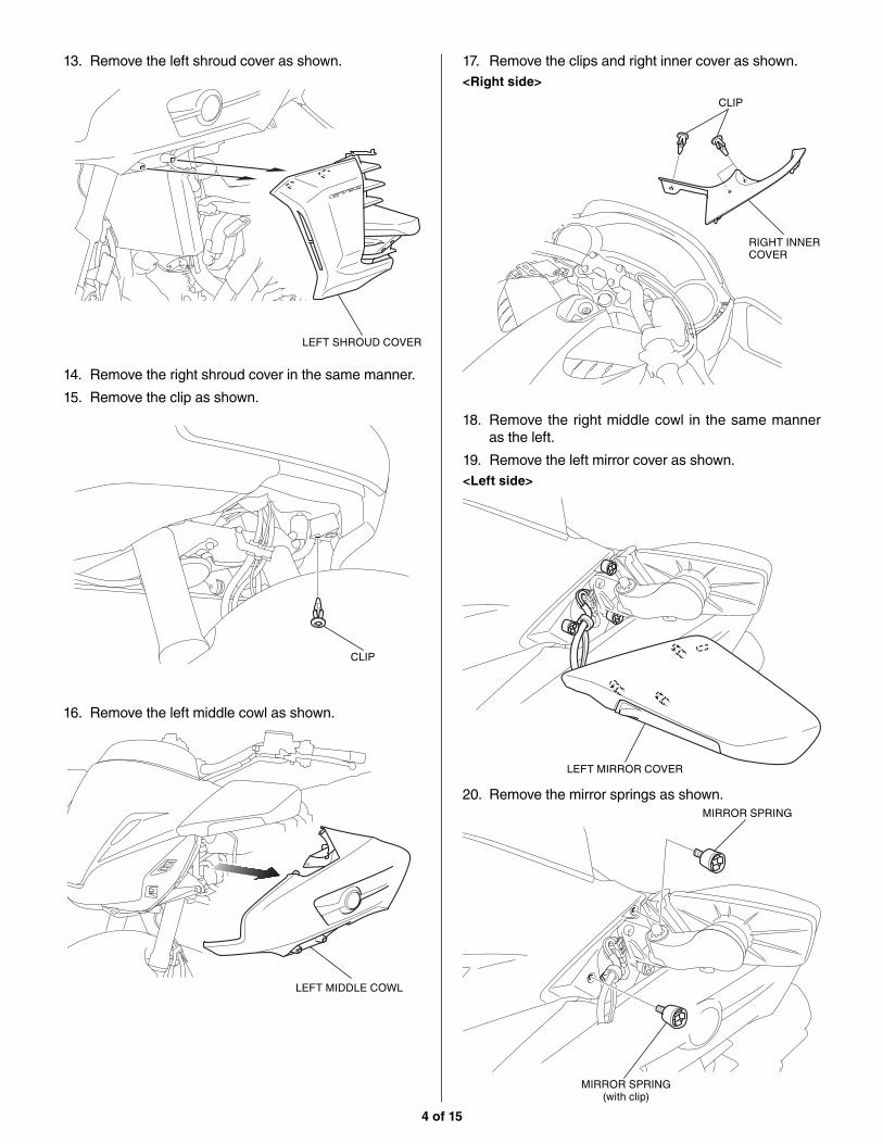
4 of 15
14. Remove the right shroud cover in the same manner.
15. Remove the clip as shown.
16. Remove the left middle cowl as shown.
CLIP
LEFT MIDDLE COWL
13. Remove the left shroud cover as shown.
LEFT SHROUD COVER
17. Remove the clips and right inner cover as shown.<Right side>
RIGHT INNER COVER
CLIP
18. Remove the right middle cowl in the same manner as the left.
19. Remove the left mirror cover as shown.<Left side>
LEFT MIRROR COVER
20. Remove the mirror springs as shown.
MIRROR SPRING (with clip)
MIRROR SPRING

5 of 15
SCREEN GARNISH
21. Repeat Steps 19 and 20 on the right side.
22. Remove the screen garnish as shown.
23. Remove the windscreen as shown.
NYLON WASHER (small)
NYLON WASHER (large)
WINDSCREEN
BOLT
24. Remove the left pocket as shown.CLIP LEFT POCKET
Open the lid.
25. Remove the right pocket in the same manner.
26. Remove the bolts as shown.
BOLT

6 of 15
27. Remove the left and right side mirror panels as shown.
CLIP
CLIP
LEFT SIDE MIRROR PANEL
RIGHT SIDE MIRROR PANEL
28. Remove the bolts as shown.
BOLT
29. Remove the meter panel as shown.
METER PANELDisconnect the connector.
BOLT
30. Remove the left cover as shown.
• Repeat on the right side.
31. Remove the clips, left side cover, and screws as shown.
CLIP
LEFT SIDE COVER
SCREWCOVER (Save)
SCREW

7 of 15
32. Remove the bolt and clip as shown.
• Repeat on the right side.
BOLT
CLIP
Pull outward slightly on the left rear cowl until the boss
is released. Disconnect the fuel lid cable as shown.
33. Remove the top shelter as shown.
TOP SHELTERDisconnect the
connector.
8-PIN WATERPROOF CONNECTOR (Gray) 3-PIN WATERPROOF
CONNECTOR (Black)
BOSS
LEFT REAR COWL
FUEL LID CABLE
MOTORCYCLE’S WIRE TIELoosen.
FUEL LID CABLERemove.

8 of 15
36. Remove the right panel switch from the shelter as shown.
RIGHT PANEL SWITCH
SHELTER
SHOP TOWEL
SCREW
37. Remove the dummy knob as shown.
RIGHT PANEL SWITCH
DUMMY KNOB (Save)
RIB
RIB
34. Place the top shelter upside down on a clean shop towel.
Remove the left dummy panel from the top shelter as shown.
SHELTER
LEFT DUMMY PANEL (Save)
SCREW
SHOP TOWEL
35. Install the accessory left side panel switch as shown.
SHELTER
LEFT SIDE PANEL SWITCH
SCREW (Reuse)
SHOP TOWEL

9 of 15
38. Install the audio power knob as shown.
39. Install the right panel switch to the shelter in the reverse order of removal.
RIGHT PANEL SWITCH (Reuse)
AUDIO POWER KNOB
41. Route the USB cord as shown.
USB CORD
<Left side>
42. Route the USB cord as shown.
USB CORD
RIB
RIB
<Left side>
40. Route the USB cord as shown.
USB CORD
USB CORD
CLIP (Reuse)Secure the USB cord to
the motorcycle’s harness.
<Right side>

10 of 15
45. Install the grommets to the audio unit stay as shown.
GROMMET
GROMMET
AUDIO UNIT STAY
46. Install the audio unit stay as shown.5 mm SCREW (short)
AUDIO UNIT STAY
AUDIO UNIT
47. Remove the tapes as shown.
ELECTRICAL TAPERemove.
48. Remove the dummy connectors as shown.
MOTORCYCLE’S 12-PIN WATERPROOF DUMMY CONNECTOR (Black) (Save)
MOTORCYCLE’S 2-PIN WATERPROOF DUMMY CONNECTOR (Black) (Save)
5 mm SCREW (short)
44. Install the USB cord stay as shown.
USB CORD STAY
5 mm SCREW (short)
AUDIO UNIT
43. Route the USB cord as shown.USB CORD

11 of 15
49. Connect the audio harness as shown.
AUDIO HARNESS
MOTORCYCLE’S 12-PIN WATERPROOF CONNECTOR (Black)
MOTORCYCLE’S 2-PIN WATERPROOF CONNECTOR (Black)
50. Route the audio harness as shown.
AUDIO HARNESS
51. Connect the assembled audio unit as shown.
AUDIO HARNESS
ASSEMBLED AUDIO UNIT
52. Connect the USB cord as shown.USB CORD
ASSEMBLED AUDIO UNIT
53. Secure the USB cord connector as shown.
ASSEMBLED AUDIO UNIT
USB CORD CONNECTOR
USB CORD STAY

12 of 15
55. Secure the assembled audio unit as shown.
6 mm FLANGE BOLT
FLANGE COLLAR
ASSEMBLED AUDIO UNIT
56. Secure the USB cord with the wire tie as shown.
54. Install the assembled audio unit as shown.
<Left side>
ASSEMBLED AUDIO UNIT
BOSS
57. Remove the dummy connector as shown.
<Left side>
MOTORCYCLE’S 6-PIN WATERPROOF CONNECTOR (White)
MOTORCYCLE’S 6-PIN WATERPROOF DUMMY CONNECTOR (White) (Save)
58. Connect the left side panel switch harness, then install the shelter in the reverse order of removal.
SHELTER (Reuse)
MOTORCYCLE’S 6-PIN WATERPROOF CONNECTOR (White)
6-PIN WATERPROOF CONNECTOR (White)
WIRE TIE Secure the USB cord to
the motorcycle’s harness.
USB CORD

13 of 15
GROMMETInstall the grommet
in the hole.
USB CORD
HOLE
59. Install the right and left pocket in the reverse order of removal.
61. Install the USB cord as shown.
<Right side>
<Left side>
62. Secure the USB cord as shown.
64. Secure the USB cord as shown.
USB CORD
63. Store the USB connector in the USB connector holder.
USB CONNECTOR
USB CONNECTOR HOLDER
WIRE TIESecure the USB cord to
the motorcycle’s harness.
WIRE TIE Secure the USB cord to
the motorcycle’s harness.
MOTORCYCLE’S WIRE TIE (Reuse)Secure the USB cord
and fuel lid cable
to the motorcycle’s
harness.
FUEL LID CABLE
SPEAKER UNIT
LEFT SPEAKER SUB CORD
65. Install the left speaker sub cord on the speaker unit as shown.
2-PIN WATERPROOF CONNECTOR (White)
60. Remove the grommet as shown.
GROMMET (Save)

14 of 15
68. Route the left speaker sub cord as shown.
<Left side>
67. Install the speaker unit as shown.
SCREW (Reuse)
SPEAKER UNIT
LEFT SPEAKER SUB CORD
69. Remove the tape from the dummy connector as shown.
ELECTRICAL TAPERemove.
71. Connect the left speaker sub cord as shown.
70. Remove the dummy connector as shown.
MOTORCYCLE’S 2-PIN WATERPROOF DUMMY CONNECTOR (White) (Save)
MOTORCYCLE’S 2-PIN WATERPROOF CONNECTOR (White)
MOTORCYCLE’S 2-PIN WATERPROOF CONNECTOR (White)
2-PIN WATERPROOF CONNECTOR (White)
LEFT SPEAKER SUB CORD
66. Route the left speaker sub cord as shown.
LEFT SPEAKER SUB CORD
SPEAKER UNIT
HOLE
GROMMETInstall the grommet
in the hole.
<Left side>
2-PIN WATERPROOF CONNECTOR (White)

15 of 15
76. Connect the right speaker sub cord as shown.
77. Install the removed motorcycle parts in the reverse order of removal.
78. Check the audio switch, speaker, headlight, and the other lights for proper operation. Check that the harnesses are not pinched or pulled taut.
RIGHT SPEAKER SUB CORD
MOTORCYCLE’S HARNESS
72. Repeat the step 65 through 67 or the right side.
73. Route the right speaker sub cord as shown.
<Right side>
RIGHT SPEAKER SUB CORD
2-PIN WATERPROOF CONNECTOR (Black)
74. Remove the tape from dummy connector as shown.
ELECTRICAL TAPERemove.
MOTORCYCLE’S 2-PIN WATERPROOF CONNECTOR (Black)
75. Remove the dummy connector as shown.
MOTORCYCLE’S 2-PIN WATERPROOF DUMMY CONNECTOR (Black) (Save)
MOTORCYCLE’S 2-PIN WATERPROOF CONNECTOR (Black)
2-PIN WATERPROOF CONNECTOR (Black)

![GKN Hybrid Power - MathWorks · GKN Hybrid Power - Background ... Gyrodrive enabled bus. Engine Torque (top chart), Engine Speed (2nd chart) ... Av = 9.1 kph. 16 [MATLAB EXPO 2014]](https://static.fdocuments.net/doc/165x107/5b91e7f909d3f25e788c858c/gkn-hybrid-power-mathworks-gkn-hybrid-power-background-gyrodrive-enabled.jpg)