PARTS LIST / TECHNICAL GUIDE - SeikoServiceCenter · PARTS LIST / TECHNICAL GUIDE ... Intermediate...
14
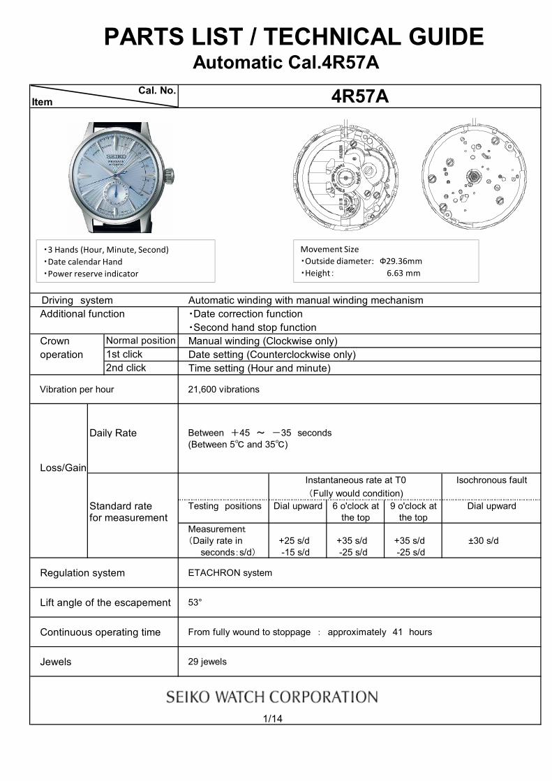
PARTS LIST / TECHNICAL GUIDE Automatic Cal.4R57A Driving system Automatic winding with manual winding mechanism Additional function ・Date correction function ・Second hand stop function Crown Manual winding (Clockwise only) operation Date setting (Counterclockwise only) Time setting (Hour and minute) Vibration per hour 21,600 vibrations Daily Rate Between +45 ~ -35 seconds (Between 5℃ and 35℃) Loss/Gain Instantaneous rate at T0 Isochronous fault (Fully would condition) Standard rate Testing positions Dial upward 6 o'clock at 9 o'clock at Dial upward for measurement the top the top Measurement (Daily rate in +25 s/d +35 s/d +35 s/d ±30 s/d seconds:s/d) -15 s/d -25 s/d -25 s/d Regulation system ETACHRON system Lift angle of the escapement 53° Continuous operating time From fully wound to stoppage : approximately 41 hours Jewels 29 jewels 1/14 Cal. No. Normal position Item 4R57A 2nd click 1st click ・3 Hands (Hour, Minute, Second) ・Date calendar Hand ・Power reserve indicator Movement Size ・Outside diameter: Ф29.36mm ・Height: 6.63 mm
Transcript of PARTS LIST / TECHNICAL GUIDE - SeikoServiceCenter · PARTS LIST / TECHNICAL GUIDE ... Intermediate...
PARTS LIST / TECHNICAL GUIDEAutomatic Cal.4R57A
Driving system Automatic winding with manual winding mechanismAdditional function ・Date correction function
・Second hand stop functionCrown Manual winding (Clockwise only)operation Date setting (Counterclockwise only)
Time setting (Hour and minute)
Vibration per hour 21,600 vibrations
Daily Rate Between +45 ~ -35 seconds(Between 5℃ and 35℃)
Loss/GainInstantaneous rate at T0 Isochronous fault(Fully would condition)
Standard rate Testing positions Dial upward 6 o'clock at 9 o'clock at Dial upwardfor measurement the top the top
Measurement(Daily rate in +25 s/d +35 s/d +35 s/d ±30 s/d seconds:s/d) -15 s/d -25 s/d -25 s/d
Regulation system ETACHRON system
Lift angle of the escapement 53°
Continuous operating time From fully wound to stoppage : approximately 41 hours
Jewels 29 jewels
1/14
Cal. No.
Normal position
Item 4R57A
2nd click1st click
・3 Hands (Hour, Minute, Second)・Date calendar Hand・Power reserve indicator
Movement Size・Outside diameter: Ф29.36mm・Height: 6.63 mm
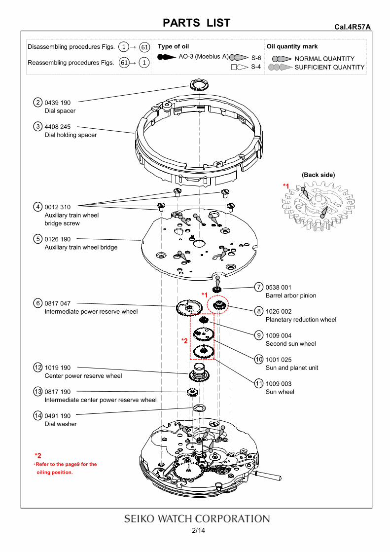
Disassembling procedures Figs. →
Reassembling procedures Figs. →
0439 190Dial spacer
4408 245Dial holding spacer
0012 310Auxiliary train wheelbridge screw
0126 190Auxiliary train wheel bridge
0538 001Barrel arbor pinion
0817 047Intermediate power reserve wheel 1026 002
Planetary reduction wheel
1009 004Second sun wheel
1001 0251019 190 Sun and planet unitCenter power reserve wheel
1009 0030817 190 Sun wheelIntermediate center power reserve wheel
0491 190Dial washer
・Refer to the page9 for the oiling position.
2/14
PARTS LIST
*2
Cal.4R57A
8
9
10
11
4
7
6
2
3
(Back side)
5
12
13
14
*1
*1
*2
Type of oil Oil quantity mark
S-6 NORMAL QUANTITYS-4 SUFFICIENT QUANTITY
AO-3 (Moebius A)61
61
1
1
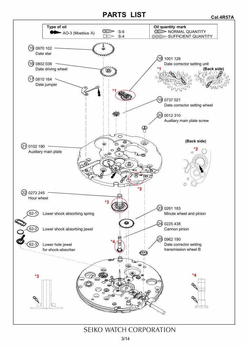
0970 102Date star
1001 1280802 036 Date corrector setting unitDate driving wheel
0810 164Date jumper
0737 021Date corrector setting wheel
0012 310Auxiliary main plate screw
0102 190Auxiliary main plate
0273 245Hour wheel
0261 183Lower shock absorbing spring Minute wheel and pinion
0225 438Lower shock absorbing jewel Cannon pinion
0962 190Lower hole jewelfor shock-absorber
3/14
16
15
17
Cal.4R57A
(Back side)
18
PARTS LIST
Date corrector settingtransmission wheel B
62-1
62-2
(Back side)
19
20
21
22
23
62-3
24
25
*4
*1
*2
*1
*4
*2
*3
*3
Type of oil Oil quantity markS-6 NORMAL QUANTITYS-4 SUFFICIENT QUANTITY
AO-3 (Moebius A)

Oscillating weight ・Refer to page 7 for each parts code・Refer to the page11 for assembling position
0012 354
0012 420 0191 183Balance cock screw Automatic train bridge
0171 354 0514 183Balance cock
0012 919Ratchet wheel screw
0285 051Ratchet wheel
0012 354Pallet bridge screw
0161 3000310 185 Pallet bridge
Balance completewith stud 0301 009
Pallet fork
Upper shock absorbing spring
Upper hole jewel for shock-absorber
4/14
Automatic train bridge screw
32-1
35
Upper shock absorbing jewel
PARTS LIST Cal.4R57A
30
33
34
1
32-3
29
26
31 27
32-2
Second reduction wheel and pinion32 28
32-4
*2
*3
*1
whole tooth
*1
*2
*3
Type of oil Oil quantity markAO-3 (Moebius A) S-6 NORMAL QUANTITY
S-4 SUFFICIENT QUANTITY

0012 420
0511 010 Cap jeweled springFirst reduction wheel
・Refer to page 8 for the oiling position Cap jewel・Refer to page 10 for Disassembling/Reassembling
0831 183 0363 184Pawl lever
・Refer to the page11 for assembling0114 183Barrel and train wheel bridge・Refer to page 8 for the oiling position
0836 002Reduction wheel holder
0436 166Lower plate for barrel and trainwheel bridge
0012 3540144 245 Lower plate for barrel and trainFourth wheel and pinion wheel bridge screw
0231 070Third wheel and pinion
0012 354Center wheel bridge screw
0122 164Center wheel bridge
5/14
42
Ratchet sliding wheel spring
47
44
46
43
37
45
37-1
38
39
37-2
PARTS LIST
Barrel and train wheel bridge screw
40
Cal.4R57A
36
*1
*1
Type of oil Oil quantity markS-6 NORMAL QUANTITYS-4 SUFFICIENT QUANTITY
AO-3 (Moebius A)
41
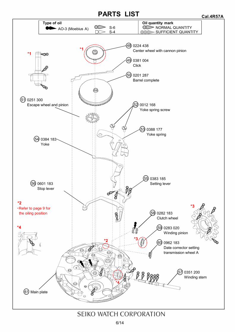
0224 438Center wheel with cannon pinion
0381 004Click
0201 287Barrel complete
0251 300Escape wheel and pinion 0012 168
Yoke spring screw
0388 177Yoke spring
0384 183Yoke
0383 1850601 183 Setting leverStop lever
・Refer to page 9 for the oiling position 0282 183
Clutch wheel
0283 020Winding pinion
0962 183Date corrector settingtransmission wheel A
0351 200Winding stem
Main plate
6/14
55
61
52
56
59
60
53
57
58
51
54
Cal.4R57A
48
49
50
PARTS LIST
*1
*3
*1
*3
*4
*4
*2
*2
Type of oil Oil quantity markS-6 NORMAL QUANTITYS-4 SUFFICIENT QUANTITY
AO-3 (Moebius A)

Oscillating weight with ball bearing
● List of screws
*All parts code are subject to change without notice.
7/14
Cal.4R57A
31
Lower plate forbarrel and trainwheel bridge screw
26
Auxiliary train wheelbridge screw (×4)Balance bridge
screw
Pallet bridge screw (×2)
PARTS LIST
42
Barrel and trainwheel bridge screw (×3)
Automatic trainbridge screw (×2)
33
0012 100
Parts No
46
Name
0012 3540012 919 Center wheel bridgescrew
Name Parts No
29 Ratchet wheel screw
1509 194
25
Parts code Marking
1509 193 Japan mark
0012 168
36
Yoke spring screw (×2)52
Auxiliary main platescrew20
4
0012 310

1.Oiling spotBarrel and train wheel bridge
[Top side]
[Back side]
Note:After oiling *2 , set Lower plate for barrel and train wheel bridge & screw.
Lower plate for barrel and train wheel bridge
Lower plate for barrel and train wheel bridge screw
After oiling *4 , set First reduction wheel & Pawl lever & Reduction wheel holder.First reduction wheel
First reduction wheel
Pawl lever
Reduction wheel holder
8/14
Cal.4R57ATECHNICAL GUIDE
39
43
42
(1)
4141
40
37
*1*1
*2
*3*2 *3*4
Type of oil Oil quantity markS-6 NORMAL QUANTITYS-4 SUFFICIENT QUANTITY
*4
AO-3 (Moebius A)

Planet unitSecond sun wheel
Notes:*2 Oil to between the Arbor pinion and the Gear.
Sun and planet unit
Sun wheel
Stop lever
Stop lever
Main plate
Contact part of Main plate and Stop lever
9/14
10
11
(3)
56
61
TECHNICAL GUIDE Cal.4R57A
9(2)
*2
Type of oil Oil quantity markS-6 NORMAL QUANTITYS-4 SUFFICIENT QUANTITY
AO-3 (Moebius A)
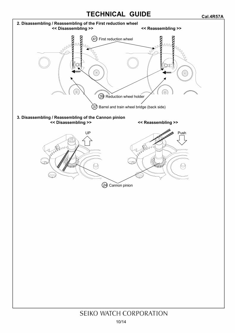
2. Disassembling / Reassembling of the First reduction wheel
First reduction wheel
Reduction wheel holder
Barrel and train wheel bridge (back side)
3. Disassembling / Reassembling of the Cannon pinion
Cannon pinion
10/14
UP
24
<< Disassembling >>
Cal.4R57A
Push
<< Reassembling >>
TECHNICAL GUIDE
39
37
<< Disassembling >> << Reassembling >>
41
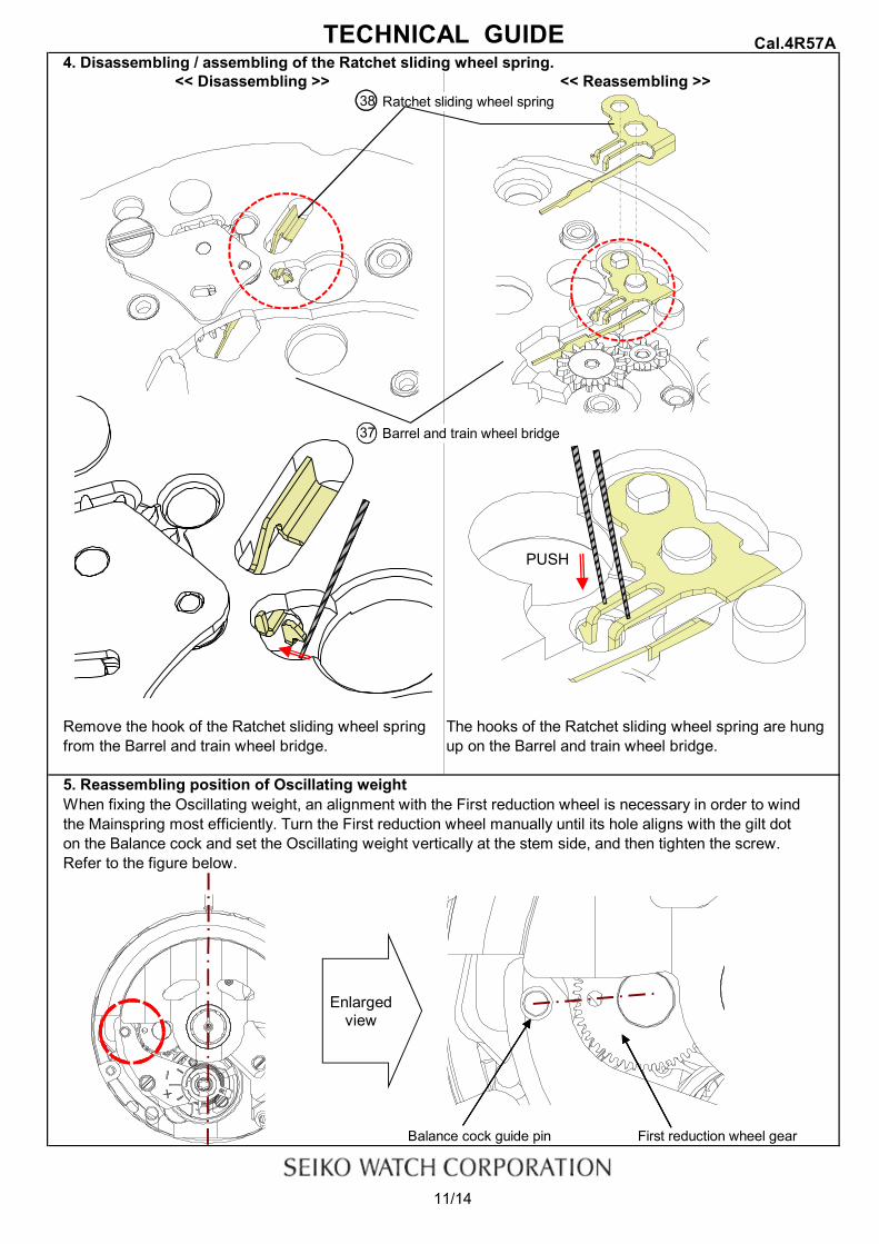
4. Disassembling / assembling of the Ratchet sliding wheel spring.
Ratchet sliding wheel spring
Barrel and train wheel bridge
5. Reassembling position of Oscillating weightWhen fixing the Oscillating weight, an alignment with the First reduction wheel is necessary in order to windthe Mainspring most efficiently. Turn the First reduction wheel manually until its hole aligns with the gilt doton the Balance cock and set the Oscillating weight vertically at the stem side, and then tighten the screw. Refer to the figure below.
Balance cock guide pin First reduction wheel gear
11/14
Cal.4R57ATECHNICAL GUIDE
Remove the hook of the Ratchet sliding wheel springfrom the Barrel and train wheel bridge.
<< Disassembling >> << Reassembling >>38
37
The hooks of the Ratchet sliding wheel spring are hungup on the Barrel and train wheel bridge.
Enlarged view
PUSH

6. How to remove the Winding stem1) Set the Winding stem to normal position.2) Pull out the Winding stem, while pushing "A"
Setting lever
Winding stem
7. Accuracy adjustment
Regulator
Regulator pinStud support
Note:・Regulator … Time adjustment ・Stud support … Beat error adjustment
・Regulator pin … Gap adjustment of Balance spring and Regulator pin
12/14
Cal.4R57A
Counterclockwise rotation No clockwise rotation
TECHNICAL GUIDE
57
55
(+) side
(-) side
A
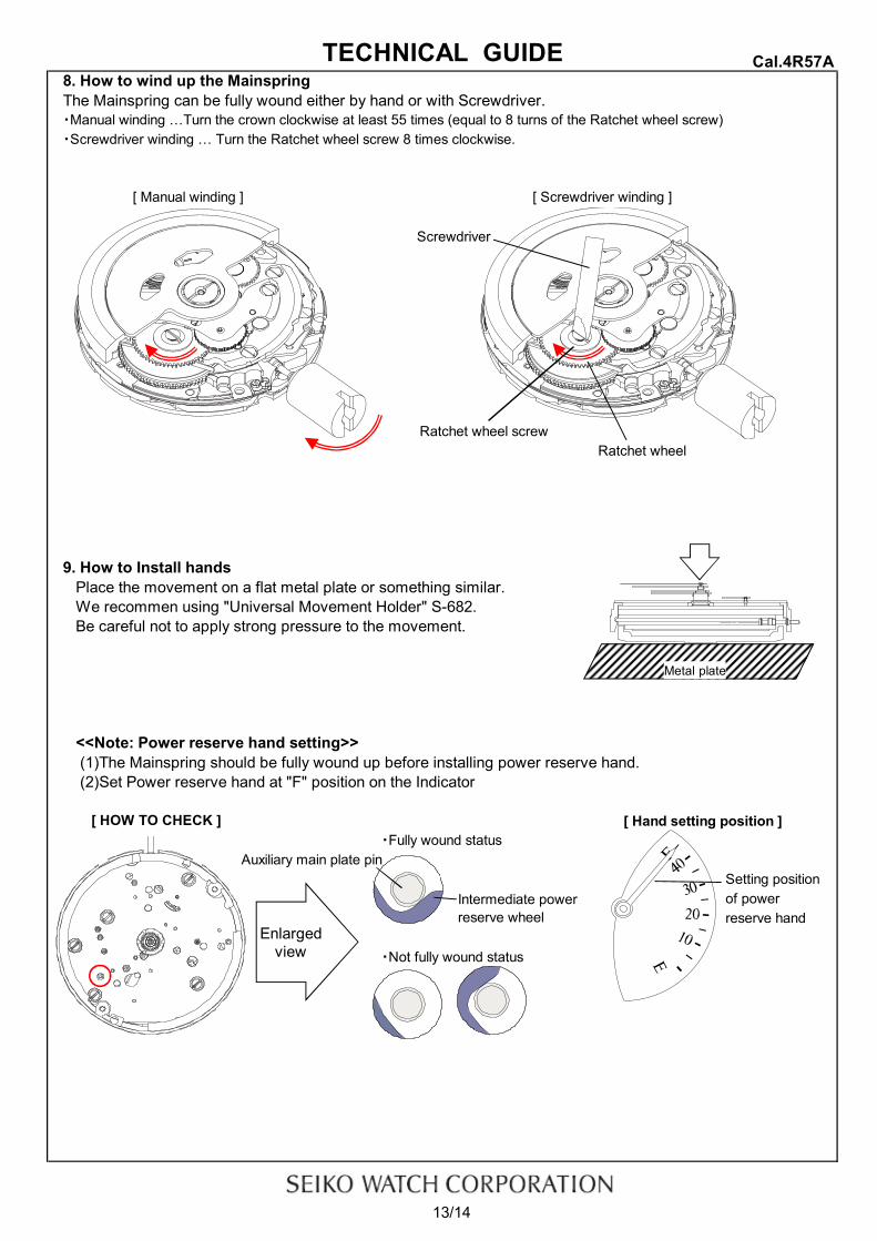
8. How to wind up the MainspringThe Mainspring can be fully wound either by hand or with Screwdriver.・Manual winding …Turn the crown clockwise at least 55 times (equal to 8 turns of the Ratchet wheel screw)・Screwdriver winding … Turn the Ratchet wheel screw 8 times clockwise.
Screwdriver
Ratchet wheel screwRatchet wheel
9. How to Install handsPlace the movement on a flat metal plate or something similar.We recommen using "Universal Movement Holder" S-682.Be careful not to apply strong pressure to the movement.
<<Note: Power reserve hand setting>> (1)The Mainspring should be fully wound up before installing power reserve hand. (2)Set Power reserve hand at "F" position on the Indicator
[ Hand setting position ]・Fully wound status
Auxiliary main plate pinSetting position
Intermediate power of powerreserve wheel reserve hand
・Not fully wound status
13/14
[ Screwdriver winding ]
TECHNICAL GUIDE Cal.4R57A
[ Manual winding ]
[ HOW TO CHECK ]
Metal plate
Enlargedview

【4R57A operation manual】
1. How to set the time1) Pull out the crown to the second click position.2) Turn the crown to set Hour and Minute hands.
(Check if AM/PM is set correctly.)3) Push the crown back into the normal position.
*If the crown is turned counterclockwise, the Date hand reverses. Please reset the Date hand.
2. How to set the Date hands1) Pull out the crown to the first click position.2) Turn the crown counterclockwise for date setting.
* Do not set the date between 9:00 P.M. and 1:30 A.M. If you do so,the date may not change properly or it may cause a malfunction.
3) Push the crown back into the normal position.
3. How to wind up the mainspringa) Manual winding … Slowly turn the crown clockwise at normal position.
* If you wind by turning the ratchet wheel screw 8 times, it will start to move naturally after shaking slightly.b) Winding up with the winding machine.
Full wind up conditions are as follows:・Rotary speed : 30 rpm・Operating time : 60 minutes
14/14
Cal.4R57AOperation Manual