Parts List Mounting Instructions -...
14
Parts List & Mounting Instructions New Holland TC18, TC21
Transcript of Parts List Mounting Instructions -...

Parts List&
Mounting Instructions
New Holland TC18, TC21

Note: All references to left and right are taken from the operator’s point of view when he/she is sitting in seat.
Page 1
New Holland TC18, TC21 Mounting Instuctions
Standard Parts List
L&R - Front Mounting Bracket
LH - Upper & Lower Front Shield
RH - Upper & Lower Front Shield
1 - Under Seat Shield
1 - Transmission Shield
1 - Loader Control Boxing
2 - ½” Spacers
2 - ¼” Spacers
2 - 3/8” Spacers
L&R - Platform Extension Shield
3” - ½” x ½” NDAX
8” - ¼” x ¾” NDAX
15” - ¼” x 1 ½” NDAX
4 - 9/16” Plug Buttons
L&R Fender Upholstery
3 - Seat Box Floormat
L&R - Platform Floormat
16’ - 180° O-Rubber
2’ - 90° O-Rubber
Standard Bolts List
18 - ¼” x ½” Flange Bolt, Yellow Dichrome
18 - ¼” Flange Nut, Yellow Dichrome
Note: All references to left and right are taken from the operator’s point of view when he/she is sitting in seat.
Page 2
New Holland TC18, TC21 Mounting Instuctions

2 - M8 x 25 Flange Bolts Yellow Dichrome
6 - ½” x 3” Hex Bolt
4 - 9/16” x 2 ½” Rubber Washers
2 - 9/16” x 2 ½” Cut Rubber Washers
4 - 9/16” x 2 ½” Steel Flat Washer
2 - 9/16” x 2 ½” Cut Steel Flat Washers
4 - 12 x 60 x 1.75 Hex Bolt
6 - 9/16” Rubber Isolators
Standard Heater Parts
2 - 3/8” NPT x 3/8” Barb 180° Fitting
2 - HS - 6 Hose Clamps
25’ - 3/8” Heater Hose
Note: All references to left and right are taken from the operator’s point of view when he/she is sitting in seat.
Page 3
New Holland TC18, TC21 Mounting Instuctions

NOTE: The electrical connection for thecab has been redesigned. The relay andcircuit breaker are now located in theheadliner of the cab.
To complete the electrical hook-up forthe cab, proceed now as follows AFTERthe cab is mounted on the tractor. Omitall steps in mounting instructions thatrefer to electrical hook-up.
Locate the wires at the bottom of theA-post.
Connect the heavy black wire to 12Vsource on the tractor.
Connect the heavy black wire to maintractor ground.
Connect the orange wire to a switchedsource on the tractor.
NOTE: All references to left and right are taken from the operator’s point of view when he/she issitting in the driver’s seat.
New Holland TC18 Addendum

Note: All references to left and right are taken from the operator’s point of view when he/she is sitting in seat.
Page 4
New Holland TC18, TC21 Mounting Instuctions
1. To prepare the tractor for mounting, firstremove the ROPS, seat, lights, grab handlesand trasmission shield. Also if the tractor isequipped with a loader, mower or mid-mountattachments, remove them as well.
2. First take the two 9/16” plug buttons andinstall them in to the two inside ROPS holes (1) in the left side fender. See Figure 1.
3. Repeat step 2 for the right side.
4. Take the left fender upholstery and locate it on the left fender up against the lever contolbox (2) and down beside the tool box. The tool box must be open for this procedure. Once theupholsery has been located properly, glue itinto place. See Figure 2.
5. Repeat step 4 for the right side.
6. Take the ¼” x 1 ½” NDAX and trim it to fit over top of the holes where the grab handle onthe left fender was located (3). See Figure 3.
7. Repeat step 6 for the right side.
8. Take the new transmission shield and move it into position where the old one was located. Reuse the top two bolts from the old shield tosecure the top of the new one (4). Then use the two M8 x 25 bolts (5) to secure the sides of theshield. See Figure 4.
9. If your machine is a TC21, remove theunderseat shield and replace with the underseatshield supplied. Take the cab underseat shield.It will be necessary to punch the holes in theupholstery, use the holes in the shield as aguide. Place the shield on top of the seatbox. Make sure that all of the holes line up correctly.
Figure 1
1
Figure 2
2
Figure 3
3
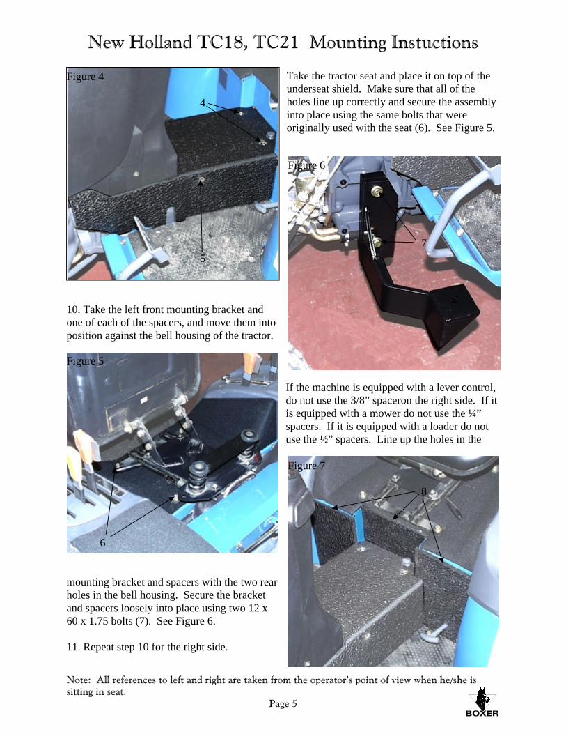
Take the tractor seat and place it on top of theunderseat shield. Make sure that all of theholes line up correctly and secure the assemblyinto place using the same bolts that wereoriginally used with the seat (6). See Figure 5.
10. Take the left front mounting bracket andone of each of the spacers, and move them intoposition against the bell housing of the tractor.
If the machine is equipped with a lever control,do not use the 3/8” spaceron the right side. If it is equipped with a mower do not use the ¼”spacers. If it is equipped with a loader do notuse the ½” spacers. Line up the holes in the
mounting bracket and spacers with the two rearholes in the bell housing. Secure the bracketand spacers loosely into place using two 12 x60 x 1.75 bolts (7). See Figure 6.
11. Repeat step 10 for the right side.
Note: All references to left and right are taken from the operator’s point of view when he/she is sitting in seat.
Page 5
New Holland TC18, TC21 Mounting Instuctions
Figure 5
6
Figure 4
4
5
Figure 6
7
Figure 7
8

12. Next take the three pieces of seat boxfloormat and move them into position on thefront of the seatbox, around the transmissionshield (8). Once they have been locatedproperly glue them into place. See Figure 7.
13. Now it is time to attach the circuit breakerand the relay. Take the circuit breaker and bolt it on to the mounting plate in the engine (9). Take the orange wire and splice it into the redand white wire on the tractor (10). Make surethat the red and white wire is ignition activated.
Then attach the other end of the wire to #86 onthe relay (11). Take the 8” black ground wireand attach the loop end to the mounting screwon the circuit breaker. Then attach the otherend to #85 on the relay (12). Take the 8” redpower wire and attach it to the auxilary pole onthe circuit breaker (13). Attach the other end to #30 on the relay (14). Run the main powerwire from the main power on the circuitbreaker (15), through the back of the enginenear the firewall and over the transmission. Make sure that the wire does not interfere withany moving parts of the engine. Connect theend of the power wire to the starter (16) on theleft side of the engine. See Figures 8, 9 andattached wiring diagram.
14. You can begin prepairing the cab formounting. Remove the door, right side escapewindow and the right lower front window from the cab. Attach the cab lifting brackets to thetop of the frame and raise the cab using a hoist.
15. Take the 180° o-rubber and begin placing it along the fender shields of the cab. Start at thefront corner of the left side shield (17), andwork your way back and around the rear shield
Note: All references to left and right are taken from the operator’s point of view when he/she is sitting in seat.
Page 6
New Holland TC18, TC21 Mounting Instuctions
Figure 8
9 13
15
10 11
14 12
Figure 9
16
Figure 10
17
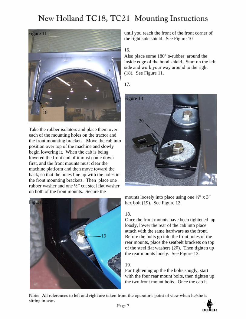
until you reach the front of the front corner ofthe right side shield. See Figure 10.
16.Also place some 180° o-rubber around theinside edge of the hood shield. Start on the leftside and work your way around to the right(18). See Figure 11.
17.
Take the rubber isolators and place them overeach of the mounting holes on the tractor andthe front mounting brackets. Move the cab into position over top of the machine and slowlybegin lowering it. When the cab is beinglowered the front end of it must come downfirst, and the front mounts must clear themachine platform and then move toward theback, so that the holes line up with the holes inthe front mounting brackets. Then place onerubber washer and one ½” cut steel flat washeron both of the front mounts. Secure the
mounts loosely into place using one ½” x 3”hex bolt (19). See Figure 12.
18.Once the front mounts have been tightened uploosly, lower the rear of the cab into placeattach with the same hardware as the front. Before the bolts go into the front holes of therear mounts, place the seatbelt brackets on topof the steel flat washers (20). Then tighten upthe rear mounts loosly. See Figure 13.
19.For tightening up the the bolts snugly, startwith the four rear mount bolts, then tighten upthe two front mount bolts. Once the cab is
Note: All references to left and right are taken from the operator’s point of view when he/she is sitting in seat.
Page 7
New Holland TC18, TC21 Mounting Instuctions
Figure 11
18
Figure 12
19
Figure 13
20

tighten up, tighten up the two front mountingbracket bolts.
20. After the cab has been mounted you canhook up the cab power wires. Take the redpower wire and run it through the side of theengine to the relay. Make sure that the wiredoes not interfere with any moving parts. Connect the wire to # 87 on the relay (21). See Figure 14. Take the black cab ground wire and run it along the inside of the engine hood, and
attach it to the the engine ground (22). SeeFigure 15
OPTIONAL STEREO HOOKUP.
21. If the cab is equiped with a stereo, take theyellow wire and run it through the back of theengine by the firewall over the transmission tothe left side of the tractor. Attach the wire to
the starter (23). See Figure 16.
Note: All references to left and right are taken from the operator’s point of view when he/she is sitting in seat.
Page 8
New Holland TC18, TC21 Mounting Instuctions
Figure 15
22
Figure 16
23
Figure 17
25
24
Figure 14
21

22. Now remove the three plug buttons on the left side of the tractor floormat. Take the leftplatform extension shield and place the insideedge on the tractor platform underneath thefloormat (24). Make sure that the outside edgeis up against the inside of the cab frame. Secure the shield into place using two of theoriginal plug buttons that were removed (25). Please note that the middle hole is no longerneeded. See Figure 17.
23. Repeat step 22 for the right side
24. Take the left upper front shield and place180° o-rubber along the inside edge that getssealed up against the tractor (25). See Figure18. Move the shield into position on the leftfrom the inside of the cab with the top flange of the shield fitting on top of the bottom flange ofthe small window shield (26). Make sure thatthe inside edge of the shield is fitting snugly
against the tractor (27). Drill one hole throughthe top of the shield, and two through the side,and secure the shield into place using three ¼”x ½” flange bolts and nuts (28). See Figure 19.
Note: All references to left and right are taken from the operator’s point of view when he/she is sitting in seat.
Page 9
New Holland TC18, TC21 Mounting Instuctions
Figure 19
28
26
27
Figure 20
30
31
Figure 21
32
Figure 18
26
28

25. Take the left side lower front shield andplace 90° o-rubber along the inside edge of theshield (29). See Figure 18. Move it intoposition at the bottom of inside of the upperfront shield around the pedal. Drill two holesthrough the top flange of the lower front shield, and the bottom flange of the upper front shield(30). Also drill two holes throught the bottomflange of the lower front shield and theplatform. For theses two holes it will benecessary to drill them up from underneath theplaftorm (31). Secure the shield into placeusing four ¼” x ½” bolts and nuts. See Figure20.
26. Repeat steps 24 and 25 for the right side.
27. If the tractor is equiped with a loader, takethe 3” piece of ½” x ½” NDAX and place it onthe the lever box behind the boot. Take the 8”piece of ¼” x ¾” NDAX and place it along thetop outside edge of the right side small window shield underneath the a-a crossmember. Takethe loader control box, and place 90° o-rubberaround the slot in the bottom (32). See Figure21. Then move the control box into positionagainst the outside of the small window shield.
Make sure that the bottom of the control box issitting on top of the lever box. Drill four holesthrough the control box flanges and secure intoplace using four ¼” x ½” bolts and nuts (33). See Figure 22.
28. Now take the left side piece of floormat and move it into position over top of the left sidemachine platform floormat and platformextension shield (34). Once you are sure that it is fitting correctly glue it into place. SeeFigure 23.
29. Repeat step 28 for the right side.
30. To complete the cab installation, use ablack silicone sealant to seal all loose andexposed edges of the newly installed floormat. Then put the door, the right side escapewindow and the right side lower front windowback on to the cab.
Note: All references to left and right are taken from the operator’s point of view when he/she is sitting in seat.
Page 10
New Holland TC18, TC21 Mounting Instuctions
Figure 22
33
Figure 23
34

Note: All references to left and right are taken from the operator’s point of view when he/she is sitting in seat.
Page 11
New Holland TC18, TC21 Heater Instuctions
1. For connecting the heater, first drain theanti-freeze from the engine. Then remove thetwo 3/8” plugs from the top of the water pump. Screw the two 3/8” NPT x 3/8” barb 180°fittings into the holes (1). Remember to use awater sealant material around the threads of the fittings. See Figure 1.
2. Take the two heater hoses running from thebottom front right corner of the cab and runthem up through the engine to the fittings. Make sure that the hoses do not interfere with
any moving parts of the engine. Take thepressure hose and attach it to the left fitting. Secure it into place using one HS-6 hose clamp (2). Take the suction hose and attach it to theright fitting. Secure it into place using oneHS-6 hose clamp (3). See Figure 2.
3. Ensure that all connections are tight andrefill the anti-freeze
4. Open the water valve approximately halfway, using the rotary control cable in theswitch plate of the cab, and turn on the fan. Start the unit and run at PTO rpm for 5
minutes. Check for leaks and addanti-freeze as required.
5. Start the unit again and drive at PTO rpmfor a few minutes to remove any air trapped inthe heater hose. Stop the unit again, check theanti-freeze and add as required. If the heaterstill does not heat, your unit will require anauxiliary water pump to help in watercirculation.
Figure 1
1
Figure 2
3
2

Electrical Connectors List
Qty Description
2 Connectors, Loop, 10GA, ¼”
1 Connectors, Loop, 10GA, ½”
1 Connectors, Loop, 10GA, 3/8”
1 Splicer, Wire, Blue
NOTE: All references to left and right are taken from the operator’s point of view when he/she issitting in the driver’s seat.
ADDENDUM ALL Mounting Instructions