PARTS AND MAINTENANCE MANUAL ELECTRIC MINUTE …Tire Condition and Pressure Tire condition should be...
59
MODELS: 898320A, 898320B, 898320EE, 898323, 898323EE Part No. 840505 Rev. J PARTS AND MAINTENANCE MANUAL ELECTRIC MINUTE MISER
Transcript of PARTS AND MAINTENANCE MANUAL ELECTRIC MINUTE …Tire Condition and Pressure Tire condition should be...

MODELS: 898320A, 898320B, 898320EE, 898323, 898323EE
Part No. 840505 Rev. J
PARTS ANDMAINTENANCE MANUAL
ELECTRIC MINUTE MISER

250–3–01–CU 2001 Textron Inc. All Rights Reserved.Lincoln, Nebraska Printed in U.S.A
1 GENERAL INFORMATION
IMPORTANT!
THIS MANUAL WILL AID YOU IN THE SAFEOPERATION AND PROPER MAINTENANCE OFYOUR EQUIPMENT. READ MANUAL THOROUGHLYBEFORE ATTEMPTING OPERATION. IF ANYPORTION IS NOT CLEARLY UNDERSTOOD,CONTACT AN AUTHORIZED DEALER FORCLARIFICATION.
To make sure you are fully aware of safety and serviceinformation, the following two symbols are usedthroughout this manual.
!! This symbol is used throughout the manual toalert you to information about unsafe actions orsituations, and will be followed by the word DANGER,WARNING, or CAUTION. DANGER indicatesimmediate hazards that may result in severe injury ordeath. WARNING indicates unsafe actions or situationsthat may cause severe injury, death and/or majorequipment or property damage. CAUTION indicatesunsafe actions or situations that may cause injury, and/orminor equipment or property damage.
NOTE: This appears next to information or instructions which will help you operate and maintain your equipment the right way.
WARNING!The information and instructions includedin this manual alert you to certain thingsyou should do very carefully. If you do not,you could:
• hurt yourself or others • hurt the next person who operates the equipment• damage the equipment.
This manual contains essential operationand safety information and must remainwith the unit at all times, within easy ac-cess of any operator.
Additional manuals are available through your dealer.
IMPORTANT!
THIS EQUIPMENT SHOULD NOT BE MODIFIED ORADDED TO WITHOUT THE MANUFACTURER’SAUTHORIZATION.
WARNING!Altering this equipment in any mannerwhich adversely affects the equipmentsoperation, performance, durability or use,may cause hazardous conditions.
Direct any inquiries to:Textron Golf,Turf and Specialty ProductsAttn: Director of Engineering ServicesP.O. Box 82409Lincoln, NE 68501–2409 USA
SPECIFICATION INFORMATION
All information contained in this manual is the latestavailable at the time of printing. Textron Golf, Turf andSpecialty Products reserves the right to make changesat any time without notice.
Whenever a name brand product is specified, anequivalent product may be used unless stated otherwise.
CHANGE OF OWNERSHIP OR ADDRESSTextron Golf, Turf and Specialty Products makes everyeffort to keep owners informed of all safety relatedinformation. Therefore, changes in ownership and/oraddress should be reported to the manufacturer.Your dealer has REGISTRATION CHANGE FORMSwhich will be filled out and filed by the dealer for hisrecords, and a copy will be sent to the manufacturer.
DEALER INFORMATIONFor your nearest dealer location write to:
Textron Golf, Turf and Specialty ProductsAttn: Sales CoordinatorP.O. Box 82409Lincoln, NE 68501–2409 USA
In the USA and Canada call 1–888–922–8873 (dealerinformation only).
OPERATOR’S MANUALS
Model 898320A use Part No. 840504. . . . . . . . . . . . . . Model 898320B use Part No. 841615. . . . . . . . . . . . . . Model 898320EE use Part No. 841615. . . . . . . . . . . . . Model 898323 use Part No. 841615. . . . . . . . . . . . . . . Model 898323EE use Part No. 841615. . . . . . . . . . . . .
SERVICE MANUAL
Models 898320A, 898320B, 898323 Part No. 2703178. . . . . . . . . . . . . . . . . .

1
TABLE OF CONTENTS
Page
1 General Information Inside Front Cover. . . . . . . . . . . . . . . . . . . . . . . . . . . . . . .
2 Identification 2. . . . . . . . . . . . . . . . . . . . . . . . . . . . . . . . . . . . . . . . . . . . . . . . . . . . .
3 Specifications 3. . . . . . . . . . . . . . . . . . . . . . . . . . . . . . . . . . . . . . . . . . . . . . . . . . .
4 Maintenance & Service
4.1 Maintenance Guide 4. . . . . . . . . . . . . . . . . . . . . . . . . . . . . . . . . . . . . . . .
4.2 Lifting The Vehicle 4. . . . . . . . . . . . . . . . . . . . . . . . . . . . . . . . . . . . . . . . .
4.3 Lubrication Guide 5. . . . . . . . . . . . . . . . . . . . . . . . . . . . . . . . . . . . . . . . . .
4.4 Rear Access 5. . . . . . . . . . . . . . . . . . . . . . . . . . . . . . . . . . . . . . . . . . . . . .
4.5 Brake Adjustment 5. . . . . . . . . . . . . . . . . . . . . . . . . . . . . . . . . . . . . . . . .
4.6 Tires 6. . . . . . . . . . . . . . . . . . . . . . . . . . . . . . . . . . . . . . . . . . . . . . . . . . . . .
4.7 Differential 7. . . . . . . . . . . . . . . . . . . . . . . . . . . . . . . . . . . . . . . . . . . . . . . .
4.8 Front & Rear Wheel Bearings 7. . . . . . . . . . . . . . . . . . . . . . . . . . . . . . .
4.9 Brush Replacement 7. . . . . . . . . . . . . . . . . . . . . . . . . . . . . . . . . . . . . . . .
4.10 Motor Terminals 7. . . . . . . . . . . . . . . . . . . . . . . . . . . . . . . . . . . . . . . . . . .
4.11 Light Bulb Replacement 7. . . . . . . . . . . . . . . . . . . . . . . . . . . . . . . . . . . .
4.12 Battery Specifications, Service And Charging 7. . . . . . . . . . . . . . . . .
4.13 Storage 8. . . . . . . . . . . . . . . . . . . . . . . . . . . . . . . . . . . . . . . . . . . . . . . . . .
4.14 Cleaning 8. . . . . . . . . . . . . . . . . . . . . . . . . . . . . . . . . . . . . . . . . . . . . . . . .
4.15 Touch-up Paint 8. . . . . . . . . . . . . . . . . . . . . . . . . . . . . . . . . . . . . . . . . . . .
5 Torque Chart 11. . . . . . . . . . . . . . . . . . . . . . . . . . . . . . . . . . . . . . . . . . . . . . . . . . .
6 Parts
6.1 Body & Rear Suspension,Models 898320A, 898320B, 898320EE 14–15. . . . . . . . . . . . . . . . . . . .
6.2 Seat, Models 898320A, 898320B, 898320EE 16–17. . . . . . . . . . . . . . .
6.3 Tool Box, Models 898323, 898323EE 18–19. . . . . . . . . . . . . . . . . . . .
6.4 Brake Pedal & Linkage 20–21. . . . . . . . . . . . . . . . . . . . . . . . . . . . . . . . .
6.5 Speed Control Pedal (A & Earlier B Models) 22–23. . . . . . . . . . . . . .
6.6 Speed Control Pedal (Later B & 898323 Models) 24–25. . . . . . . . . .
6.7 Decals 26–27. . . . . . . . . . . . . . . . . . . . . . . . . . . . . . . . . . . . . . . . . . . . . . .
6.8 Fork, Hub & Handlebars 28–29. . . . . . . . . . . . . . . . . . . . . . . . . . . . . . . .
6.9 Differential 30–31. . . . . . . . . . . . . . . . . . . . . . . . . . . . . . . . . . . . . . . . . . . .
6.10 Electrical Components 32–35. . . . . . . . . . . . . . . . . . . . . . . . . . . . . . . . .
6.11 Motor (G.E.) 36–37. . . . . . . . . . . . . . . . . . . . . . . . . . . . . . . . . . . . . . . . . .
6.12 Motor (Advanced DC) 38–39. . . . . . . . . . . . . . . . . . . . . . . . . . . . . . . . . .
6.13 Steering Wheel Accessory 40–41. . . . . . . . . . . . . . . . . . . . . . . . . . . . . .
6.14 Battery Charger 42–43. . . . . . . . . . . . . . . . . . . . . . . . . . . . . . . . . . . . . . .
6.15 EE Components 44–45. . . . . . . . . . . . . . . . . . . . . . . . . . . . . . . . . . . . . . .
6.16 Accessories 46. . . . . . . . . . . . . . . . . . . . . . . . . . . . . . . . . . . . . . . . . . . . . .
7 Wiring Diagrams 48–53. . . . . . . . . . . . . . . . . . . . . . . . . . . . . . . . . . . . . . . . . . . . .

2 IDENTIFICATION
2
2 IDENTIFICATION
THE PRODUCT MODEL NUMBER, MODEL YEARAND SERIAL NUMBER MUST APPEAR ON ALL COR-RESPONDENCE CONCERNING THIS UNIT. Theseidentification numbers appear on the decal attached tothe left side of the kick panel. See Figure 1.
1
FIGURE 11. Model Number, Model Year and Serial Number
The model number is also stamped on top of the framecrossmember beneath the rear deck. The vehicle serialnumber and model number also appear on top of the rearcrossmember under the deck. See Figure 2.
1
FIGURE 21. Serial and Model Numbers on Rear
Crossmember

SPECIFICATIONS 3
3
3 SPECIFICATIONS
BrakesService: Rear wheel, self-adjusting drum brakesParking: Toe lock on brake pedal
PowerMotor: 24-volt, DC series; direct driveHorsepower: 1.5 hp at 2800 rpm; 4.3 hp at 1200 rpmDifferential : Bevel gear with spur and helical gear
reduction
Electrical SystemBatteries: four 6 volt, 225 amp hr. batteriesCharging: 115 volt AC, 24 volt DC, 25 amp built-in Lestronic II automatic chargerSpeed ControlProgrammable 250–amp electronic speed controllerLED Battery Condition MeterArcless Direction Control SwitchOptional244 amp hr. batteries
PerformanceRated Capacity: 550 lbs. (249 kg); includes 200 lbs. (91 kg) for operatorSpeed: 10.5 mph (16.9 km/h) maximum
SteeringHandlebar (wheel type steering optional)
SuspensionFront: Rubber mounted torque armRear: Heavy-duty coil springs with shock absorber
Seats1-passenger, vinyl-clad seat and backrest; backrest pivots downward to provide seating for 1 passenger; operator presence seat switch
TiresSize: 4.80 x 8, load range B, optional solid or foam filledPressure: 60 psi (345 kPa) cold
DimensionsHeight: 39” (991 mm) to top of handlebarLength: 85” (2.2 M)Width: 30” (762 mm)Cargo Area: 22.75” x 28.5” x 4” (578 mm x 724 mm x 102 mm)Weight: 690 lbs. (313 kg) with batteriesWheelbase: 53” (1.3 M)Rear Wheel Tread: 25.8” (655 mm)Handlebar Steering:
Clearance: 53” (1.3 M) minimum intersecting aisleInside Clearance Circle: Turnabout rear wheelOutside Clearance Circle: 130” (3.3 M)
Wheel–type Steering (Optional):Clearance: 56” (1.4 M) minimum intersecting aisleInside Clearance Circle: 46” (1.2 M)Outside Clearance Circle: 154” (3.9 M)
RangeUp to 35 miles (56 km).
Note: Range can vary depending on a number of fac-tors, including battery size and condition, payload,number of stops, tire pressure, speed, temperature,and operating terrain.
Special ToolsController Programmer Part No. 893052. . . . . . . Battery Hydrometer Part No. 841056. . . . . . . . . . . Capacitor Discharge Resistor Part No. 841148. Fluke 10 Meter Part No. 841057. . . . . . . . . . . . . . .

4 SERVICE AND MAINTENANCE
4
4.1 MAINTENANCE GUIDE
Regular servicing and preventive maintenance will helpensure that your vehicle performs at its best.
The following maintenance guide lists recommendedtasks, schedules and necessary lubricants/sprays.
EP =Extreme pressure lubePG =Pressure gun grease (lithium base)SAE = 80-90 multigradeTP =Terminal protector spray (Part No. 841192)
As Required Check differential lube level.
Remove and clean wire terminals, battery terminals and batteries, reinstall wire terminals. (TP)
Daily Check service/parking brake; adjust as necessary.
Check operation of backup alarm when direction selectoris in Reverse.
Examine tires for cuts or excessive wear.
Check wheels for bent rims, missing or loose lug nuts.
Recharge batteries to full charge state.
Weekly Check tire pressure.
Fill batteries to proper level and check specific gravity.
Every 50 Hours Perform previous checks.
Check front fork for damage or missing hardware.
Check front wheel alignment.
Every 500 Hours Perform previous checks.
Lube fork pivot bushing and brake pedal pivot. (PG)
Lube and adjust service/parking brake. (PG)
Every 1000 Hours Perform previous checks.
Change differential lube. (EP)
Clean and repack front wheel bearings. (PG)
Check motor brushes.
4.2 LIFTING THE VEHICLE
WARNING!When raising the vehicle, use jack stands toprovide adequate support and test the stabilityof the vehicle on the stands. DO NOT rely onhydraulic or mechanical jacks for support.
Place chocks in front of and behind the wheelsnot being raised.
Do not attempt to raise the rear wheels withoutfirst raising the front of the vehicle and sup-porting on jack stands.
Due to the low ground clearance and short wheel base,the vehicle should be raised only enough to remove thefront axle or the rear wheels.
Servicing that requires access to the underside of thevehicle should be accomplished by raising the front of thevehicle with a chain hoist attached to the front framemembers. Always use an additional safety chain and jackstands to prevent injury in the event of a hoist malfunc-tion.

SERVICE AND MAINTENANCE 4
5
4.3 LUBRICATION GUIDE
Use the following lubrication guide to identify lubricationpoints. Use a lithium-based lubricant.
12
XX
XX
X JACKING AND JACK STAND LOCATIONS
LUBRICATION AREANUMBER OFLUBRICATION POINTSOR FITTINGS*
1. Fork pivot bushing 12. Brake pedal pivot 1
* Use a lithium base pressure gun grease.
4.4 REAR ACCESS
The cargo area floor may be removed to provide accessto the brakes, differential and drive motor.
WARNING!The cargo area floor is a machinery guard andits removal exposes the operator to movingparts. Keep hands, hair and clothing away frommoving parts.
4.5 BRAKE ADJUSTMENT
Properly adjusted brakes should not drag when thewheels are turned. If a brake adjustment is needed, com-plete the following steps and refer to Figures 3 and 4.
1. Loosen the nut securing the front clevis.
2. Remove the cotter pin, washer and clevis pin.
3. Turn the clevis on the brake rod as required toachieve 1/4” (6.4 mm) pedal free travel. Free travel ismovement of the pedal without activating the brake.
4. Reinstall the clevis pin and washer.
5. Install a new cotter pin and tighten the clevis nut.
1
6
2
3
4
5
FIGURE 3
1. Brake Rod 4. Clevis Pin2. Nut 5. Washer3. Front Clevis 6. Cotter Pin
FLOORBOARD
1/4” (6.4 mm)FREETRAVEL
PEDAL
RULER
FIGURE 4
4 SERVICE AND MAINTENANCE
6
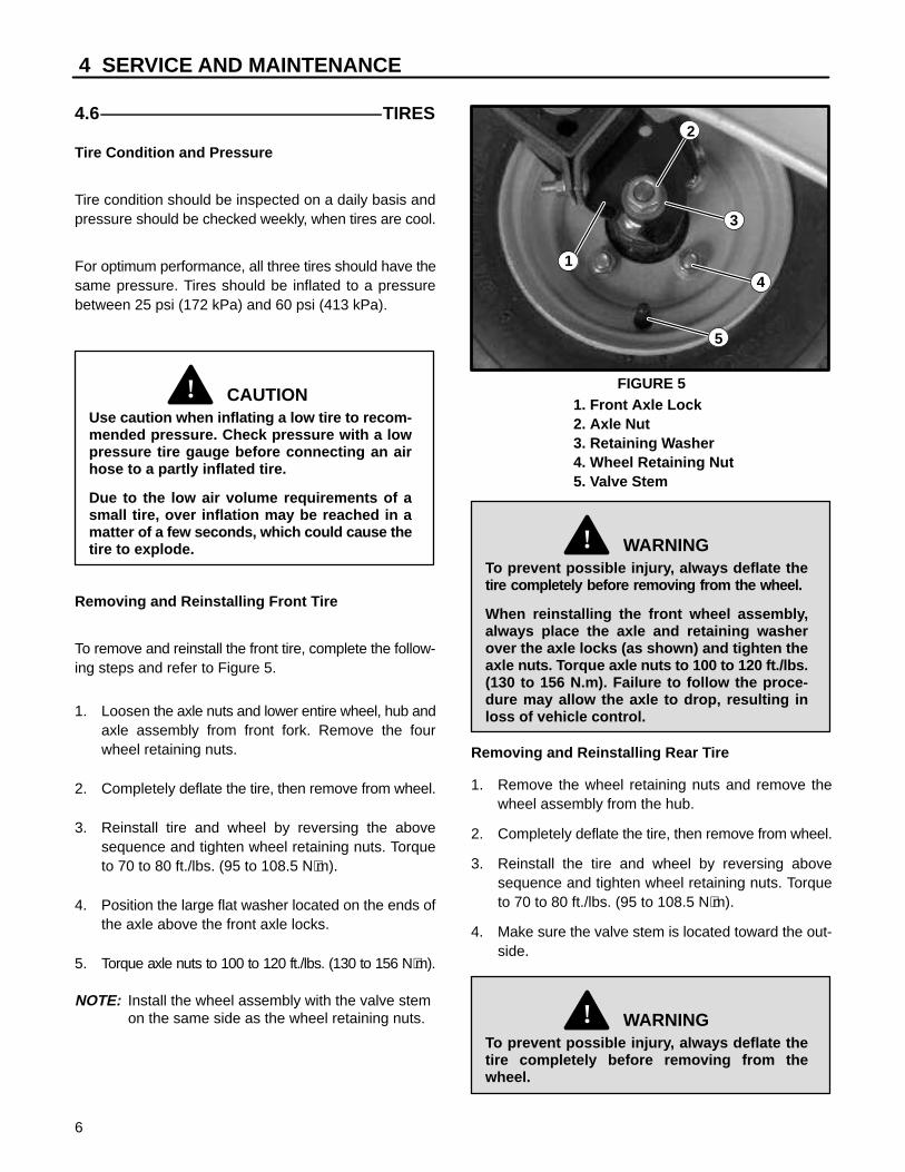
4.6 TIRES
Tire Condition and Pressure
Tire condition should be inspected on a daily basis andpressure should be checked weekly, when tires are cool.
For optimum performance, all three tires should have thesame pressure. Tires should be inflated to a pressurebetween 25 psi (172 kPa) and 60 psi (413 kPa).
CAUTION!Use caution when inflating a low tire to recom-mended pressure. Check pressure with a lowpressure tire gauge before connecting an airhose to a partly inflated tire.
Due to the low air volume requirements of asmall tire, over inflation may be reached in amatter of a few seconds, which could cause thetire to explode.
Removing and Reinstalling Front Tire
To remove and reinstall the front tire, complete the follow-ing steps and refer to Figure 5.
1. Loosen the axle nuts and lower entire wheel, hub andaxle assembly from front fork. Remove the fourwheel retaining nuts.
2. Completely deflate the tire, then remove from wheel.
3. Reinstall tire and wheel by reversing the abovesequence and tighten wheel retaining nuts. Torqueto 70 to 80 ft./lbs. (95 to 108.5 N⋅m).
4. Position the large flat washer located on the ends ofthe axle above the front axle locks.
5. Torque axle nuts to 100 to 120 ft./lbs. (130 to 156 N⋅m).
NOTE: Install the wheel assembly with the valve stem on the same side as the wheel retaining nuts.
1
5
4
2
3
FIGURE 51. Front Axle Lock2. Axle Nut3. Retaining Washer4. Wheel Retaining Nut5. Valve Stem
WARNING!To prevent possible injury, always deflate thetire completely before removing from the wheel.
When reinstalling the front wheel assembly,always place the axle and retaining washerover the axle locks (as shown) and tighten theaxle nuts. Torque axle nuts to 100 to 120 ft./lbs.(130 to 156 N.m). Failure to follow the proce-dure may allow the axle to drop, resulting inloss of vehicle control.
Removing and Reinstalling Rear Tire
1. Remove the wheel retaining nuts and remove thewheel assembly from the hub.
2. Completely deflate the tire, then remove from wheel.
3. Reinstall the tire and wheel by reversing abovesequence and tighten wheel retaining nuts. Torqueto 70 to 80 ft./lbs. (95 to 108.5 N⋅m).
4. Make sure the valve stem is located toward the out-side.
WARNING!To prevent possible injury, always deflate thetire completely before removing from thewheel.

SERVICE AND MAINTENANCE 4
7
NOTE: Improper inflation will shorten tire life.
Air pressure needed is determined by payload carried.
Use replacement tires that meet or exceed original equipment specifications.
4.7 DIFFERENTIAL
The differential capacity is 10 oz. (.3 L) of E.P. SAE 80-90multigrade lubricant. The lubricant should be maintainedas indicated by the oil level check/fill plug, shown in Fig-ure 6.
1
FIGURE 6
1. Check/Fill Plug
NOTE: Do not fill the differential with more lubricant thanrequired.
4.8 FRONT & REAR WHEEL BEARINGS
The front wheel bearings are of the tapered roller type.The rear wheel bearings are sealed ball bearings. Seeyour authorized Cushman dealer for any bearing servicerequired.
4.9 BRUSH REPLACEMENT
At regular maintenance intervals, the motor brushesshould be checked for wear or damage. See your autho-rized Cushman dealer for any service required.
4.10 MOTOR TERMINALS
Motor wire to motor terminal connections should be cleanand tight for maximum motor efficiency and to avoidmotor damage. The wire terminal retaining nuts shouldbe torqued to 50 to 70 in./lbs. (5.5 to 8 N⋅m). Do not turnthe motor terminals from their original position.
NOTE: On EE units, be sure to replace terminal boots.
4.11 LIGHT BULB REPLACEMENT
For vehicles with a headlight, replace the headlight bulbby pivoting the light forward and removing the two Phillipshead screws from the back side. Separate the lightassembly, insert the new bulb, and secure with thescrews previously removed.
To replace a taillight bulb, roll the rubber bezel fromaround the edge of the taillight and remove the lens.Replace bulb and secure lens.
NOTE: On EE units, be sure to replace head light and rear light guards.
4.12 BATTERY SPECIFICATIONS,SERVICE AND CHARGING
Specifications
This vehicle requires four “golf cart type” 6 volt batteries,each with a minimum capacity of 180 A.H. (ampere-hours at the SAE 20-hour rate) and 5/16” (8 mm) studposts.
The maximum case dimensions are:
Length 10 3/8” (264 mm). . . . . . . . . . . . . . . . . . . . . . . . . . Width 7 3/16” (183 mm). . . . . . . . . . . . . . . . . . . . . . . . . . . Height (including posts) 11 5/8” (295 mm). . . . . . . . . . .
Batteries should be connected as shown in Figure 7.
BB
TO PMCCONTROLLER
FRONTOFVEHICLE
(12V)
TO CIRCUITBREAKER 6V 6V
6V 6V
(24V) (0V)(GND)R R B B
TO CIRCUITBREAKER TO CHARGER
TO CHARGER
BW/B
FIGURE 7

4 SERVICE AND MAINTENANCE
8
Service and Charging
Preventive maintenance and regular charging will helpmaximize battery performance and life. Preventive main-tenance includes:• keeping terminations tight• checking electrolyte level and adding water as nec-
essary• cleaning the batteries and terminations• treating terminals with terminal protection spray
(Part No. 841192)Batteries should also be properly charged after each dayof vehicle use. The standard vehicle is equipped with abuilt-in 24 volt, 25 amp DC, 120 volt AC, 60 Hz, fully auto-matic charger located under the operator’s seat. Thecharger is designed to shut off automatically when thebattery set is fully charged.
Be certain to observe the following safety precautionswhen working with vehicle batteries:
WARNING!Wear safety glasses when working with batter-ies. Battery electrolyte is an acidic solution andshould be handled with care. If electrolyte isspilled or splashed on any part of the body,immediately flush the exposed area with liberalamounts of water and obtain medical attentionimmediately.
Keep all smoking materials, open flame orsparks away from the batteries.
WARNING!Hydrogen gas, which can be explosive, isformed when charging batteries. Do not chargebatteries without adequate ventilation.
Do not attempt to recharge the batteries with acharger not designed for this vehicle.
Undertrained/unauthorized persons shouldNEVER attempt to service or recharge the bat-teries of this vehicle.
To avoid possible injury, use an adequate lift-ing device to lift the batteries.
NEVER use metal chains to lift batteries, asthey can cause electrical arcing which mayresult in battery explosion.
Before charging batteries, ensure the following:• Electrolyte levels in all cells are at the recommended
level and the plates are covered.• The area in which the batteries will be charged is well
ventilated and capable of removing the hydrogengas that is generated by the charging process.
• The charging connector components are clean andin good condition.
• The charger is turned off before connecting or dis-connecting.
4.13 STORAGEIf the vehicle is to be stored for a prolonged period, cleanand reconnect the batteries, connecting wires and bat-tery racks. Make sure the batteries are fully charged.
Check the state of charge of the batteries every 30 daysand recharge as necessary to maintain the specific grav-ity above 1.230 (corrected for electrolyte temperature*).
*Hydrometer readings should be increased .004 forevery 10 degrees F. (5.5oC) above 80 degrees F. (27oC)and decreased .004 for every 10 degrees F. (5.5oC)below 80 degrees F. (27oC).
WARNING!Wear safety glasses when working with batter-ies. Battery electrolyte is an acidic solution andshould be handled with care. If electrolyte isspilled or splashed on any part of the body,immediately flush the exposed area with liberalamounts of water and obtain medical attentionimmediately.
4.14 CLEANINGTo maintain vehicle appearance, adhere to the followingguidelines for cleaning:• Clean vinyl seat and plastic or rubber trim with a mild
soap solution applied with a sponge or soft brush andwipe with a damp cloth.
• Remove oil, tar, asphalt, etc. with commercial rub-ber/vinyl cleaner.
• Wash painted surfaces with lukewarm or cold water and mild soap. Do not use harsh soap or chemicaldetergents.
• Occasionally flush the underbody with plain water to remove corrosive materials and dust. If sediment is packed in closed areas, loosen to ease removal.
NOTE: Make sure vehicle is dry before operating.4.15 TOUCH-UP PAINTSafety Yellow (lead free)
• 16 oz. (0.5L) spray can Part No. 833252. . . . . . . • 1 qt. (0.95L) can Part No. 833251. . . . . . . . . . . . .

PROGRAMMABLE SPEED CONTROLLER 5
9
PROGRAMMABLE SPEED CONTROLLER
The vehicle is equipped with an electronic speed control-ler that does not require servicing.
Controller LED Status Indicator
3
4
DIAGNOSTICS AND TROUBLESHOOTINGLED DIAGNOSTICS
OFF
0
1 2
MAIN PLUG
CURRENT LIMIT
ACCEL. CREEP LOW
SPEED LIMIT
3
4OFF
0
1 2
3
4OFF
0
1 2
3
4OFF
0
1 2
3
4OFF
0
1 2
During normal operation, with no faults present, the Status LED flashes a singleflash at approximately 1 flash/second. If the controller detects a fault, a 2–digitcode (see Table) is flashed continuously until the fault is corrected. For exam-ple, code “3,2” –welded direction contactor – appears as:
(3,2) (3,2) (3,2)
STATUSLED
5 PROGRAMMABLE SPEED CONTROLLER
10
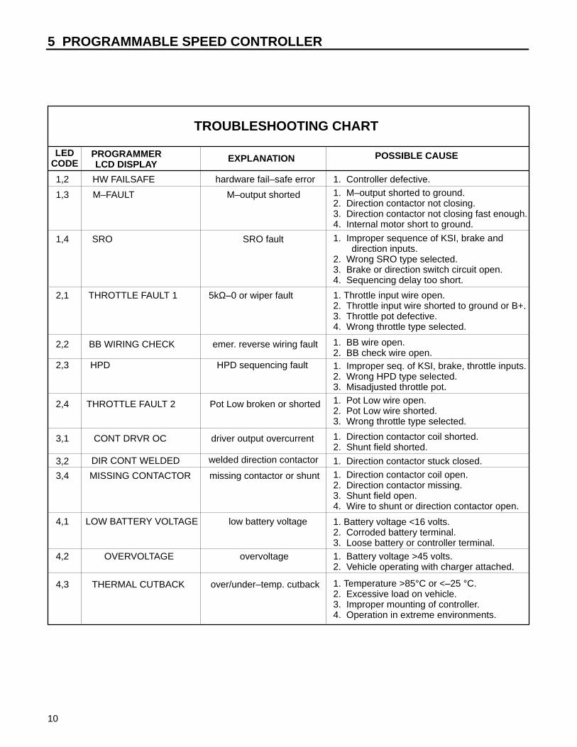
TROUBLESHOOTING CHART
LEDCODE
PROGRAMMERLCD DISPLAY
EXPLANATION POSSIBLE CAUSE
1,2 HW FAILSAFE hardware fail–safe error 1. Controller defective.
1,3 M–FAULT M–output shorted 1. M–output shorted to ground.2. Direction contactor not closing.3. Direction contactor not closing fast enough.4. Internal motor short to ground.
1,4 SRO SRO fault 1. Improper sequence of KSI, brake and direction inputs. 2. Wrong SRO type selected.3. Brake or direction switch circuit open.4. Sequencing delay too short.
2,1 THROTTLE FAULT 1 5kΩ–0 or wiper fault 1. Throttle input wire open.2. Throttle input wire shorted to ground or B+.3. Throttle pot defective.4. Wrong throttle type selected.
2,2 BB WIRING CHECK emer. reverse wiring fault 1. BB wire open.2. BB check wire open.
2,3 HPD HPD sequencing fault 1. Improper seq. of KSI, brake, throttle inputs.2. Wrong HPD type selected.3. Misadjusted throttle pot.
2,4 THROTTLE FAULT 2 Pot Low broken or shorted 1. Pot Low wire open.2. Pot Low wire shorted.3. Wrong throttle type selected.
3,1 CONT DRVR OC driver output overcurrent 1. Direction contactor coil shorted.2. Shunt field shorted.
3,2 DIR CONT WELDED welded direction contactor 1. Direction contactor stuck closed.
3,4 MISSING CONTACTOR missing contactor or shunt 1. Direction contactor coil open.2. Direction contactor missing.3. Shunt field open.4. Wire to shunt or direction contactor open.
4,1 LOW BATTERY VOLTAGE low battery voltage 1. Battery voltage <16 volts.2. Corroded battery terminal.3. Loose battery or controller terminal.
4,2 OVERVOLTAGE overvoltage 1. Battery voltage >45 volts.2. Vehicle operating with charger attached.
4,3 THERMAL CUTBACK over/under–temp. cutback 1. Temperature >85°C or <–25 °C.2. Excessive load on vehicle.3. Improper mounting of controller.4. Operation in extreme environments.

PROGRAMMABLE SPEED CONTROLLER 5
11
3
4
MANUAL ADJUSTMENTS
OFF
0
1 2
MAIN PLUG
CURRENT LIMIT
ACCEL. CREEP LOW
SPEED LIMIT
3
4OFF
0
1 2
3
4OFF
0
1 2
3
4OFF
0
1 2
3
4OFF
0
1 2
STATUSLED
Five parameters – high speed main current limit, high speed plug current limit,acceleration rate, creep speed and low speed – can be adjusted manually with asmall insulated screwdriver. The five potentiometers are accessed through holeson the adjustment panel, located under the sliding protective cover on top of thecontroller.
The pot’s relative position indicates the approximate value over the allowablerange. For example: if the main current limit range is 20 to 250 amperes, position“0” corresponds to 20 amperes and position “4” to 250 amperes. Setting the posthalfway (at position “2”) corresponds to approximately 135 amperes.
The main and plug current limit pots affect only the high speed mode ofoperation.
The low speed settings of main and plug current limit can only be changed by theprogrammer. If the high speed input is not connected, or if anti–tiedown is acti-vated, the current limit pots will have no effect on operation as the controller is oper-ating in low speed mode. NOTE: It may be possible to manually adjust the highspeed current limit pots below the programmed low speed current limit settings.Should this occur, low speed would have higher current limits than high speed.

5 PROGRAMMABLE SPEED CONTROLLER
12
CUSHMAN FACTORY SET CONTROLLER PARAMETERS
PARAMETER RANGE DEFAULT DESIRED UNITS DESCRIPTION
Current Limit, Main 20 – 250 250 250 Amps Maximum current forward speed
Current Limit,Low Speed Main
20 – 250 250 250 Amps Maximum current reverse speed
Current Limit, Plug 20 – 250 70 70 Amps Max. plug current forward speed
Current Limit,Low Speed Plug
20 – 250 70 70 Amps Max. plug current reverse speed
Current Limit,Emergency Reverse
20 – 250 140 250 Amps Max. plug current inemergency reverse
Current Limit, Low SpeedEmergency Reverse
20 – 250 140 250 Amps Max. plug current in low speedemergency reverse
Current Limit, Ramp Start 20 – 250 140 250 Amps Max. plug current duringramp start
Current Limit, Low SpeedRamp Start
20 – 250 140 250 Amps Max. plug current during rampstart in low speed
Acceleration Rate 0 – 3 1 0.8 Sec. Time to reach full outputfrom zero output
Quick Start 0 – 6 1.4 0.2 Output will respond to rate ofthrottle change
Throttle Type type 1, 2, 3 type 1 type 2 Ω or V Type of throttle inputtype 2 = 0–5V, 3–wire pot
Ramp Shape 20 – 70 50 50 % Adjust desired PWM output at50% throttle to vary throttle sensi-
tivity at low speed
Creep Speed/Min. Duty Cycle 0 – 25 10 0 % Speed at min. throttle setting
Low Speed 40 – 100 60 55 % Max. speed in reverse
High Speed 40 – 100 100 100 % Max. speed in forward
Emergency Reverse Speed 25 – 100 100 100 % Speed during emergency reverse
Sequencing Delay 0 – 3 0 0 Sec. Delays HPD and SRO from brakeafter controller is enabled
Variable Plug On/Off On On On = plug current dependent uponthrottle position. Off = fixed
High Pedal Disable (HPD) 0–2 0 1 Option to disable controller ifthrottle is applied before brake or
keyswitch input (KSI)
Static Return To Off(SRO)
type 0, 1, 2 type 1brake
type 0No SRO
Sequencing of KSI or brake beforedirection is selected
Anti–tiedown On/Off On Off Prevents high speed mode if HSSin not released after brake
Factory Settings

TORQUE CHART 6
13
M4 M5 M6 M7 M8 M10 M12 M14 M16 M18 M20 M22 M24 M27
N·m 2 4 7 11 18 32 58 94 144 190 260 368 470 707
ft.-lb. 1.5 3 5.2 8.2 13.5 24 43.5 70.5 108 142 195 276 353 530
N·m 3 6 10 16 25 47 83 133 196 269 366 520 664 996
ft.-lb. 2.2 4.5 7.5 12 18.8 35.2 62.2 100 147 202 275 390 498 747
N·m 3.6 7 11 20 29 58 100 159 235 323 440 628 794 1205
ft.-lb. 2.7 5.2 8.2 15 21.8 43.5 75 119 176 242 330 471 596 904
1/4 5/16 3/8 7/16 1/2 9/16 5/8 3/4 7/8 1 1 1/8
ft.-lb. 9 18 31 50 75 110 150 250 378 583 782
N·m 12 24 42 68 102 150 203 339 513 790 1060
ft.-lb. 13 28 46 75 115 165 225 370 591 893 1410
N·m 18 38 62 108 156 224 305 502 801 1211 1912
ft.-lb. 24 40
N·m 33 54
TORQUE SPECIFICATIONSHEX HEAD CAP SCREWS
* Grade 5 marking – Minimum commercial quality (Lower quality not recommended).
U.S. Standard Hardware
GradeShank Size (Diameter in inches, fine or coarse thread)
SAE grade5 *
SAEgrade8 **
FlangelockScrew w/FlangelockNut
The torque values shown should be used as a general guideline when specific torque values are not given.
** Grade 8 marking –
GradeShank Size (Diameter in millimeters, fine or coarse thread)
Grade8.8*
Grade10.9**
Grade12.9 ***
Metric Standard Hardware
* Grade 8.8 marking – ** Grade 10.9 marking – *** Grade 12.9 marking –8.8 10.9 12.9

6.1 BODY & REAR SUSPENSION
14
OLD POWERFRAMEREPLACEDBY NEW ONEPIECEFRAME
1
2
MODELS 898320A, 898320B, 898320EE
1
2
3
4
5
6
7
8
9
10
11
12
13
14
15
16
17
18
19
20
2122
23
24
25
26
27
28
29
30
31
22
21
10

BODY & REAR SUSPENSION 6.1
15
1 103867 Washer, 5/16 3. . . . . . . . . . . . . . . . . . . . . . . . . . . . . . . . 2 120166 Lockwasher, 1/2 6. . . . . . . . . . . . . . . . . . . . . . . . . . . . . 3 120177 Lockwasher, 3/8 4. . . . . . . . . . . . . . . . . . . . . . . . . . . . . 4 306325 Lockwasher, 5/16 1. . . . . . . . . . . . . . . . . . . . . . . . . . . . 5 306396 Lockwasher, 1/4 4. . . . . . . . . . . . . . . . . . . . . . . . . . . . . 6 306562 Nut, 3/8–16 4. . . . . . . . . . . . . . . . . . . . . . . . . . . . . . . . . 7 306835 Screw, 3/8–16 x 1 1/4 4. . . . . . . . . . . . . . . . . . . . . . . . 8 311392 Screw, 7/16–14 x 2 2. . . . . . . . . . . . . . . . . . . . . . . . . . . 9 548013 Screw, 1/4–20 x 1/2 PTH 2. . . . . . . . . . . . . . . . . . . . . . 10 548912 Nut, lock 7/16–14 2. . . . . . . . . . . . . . . . . . . . . . . . . . . . 11 800026 Screw,1/4–20 x 3/4 PTH 4. . . . . . . . . . . . . . . . . . . . . . 12 800315 Nut, wing 5/16–18 1. . . . . . . . . . . . . . . . . . . . . . . . . . . . 13 800546 Screw, M12–1.25 x 35mm 4. . . . . . . . . . . . . . . . . . . . 14 800875 Nut, M12–1.25 4. . . . . . . . . . . . . . . . . . . . . . . . . . . . . . . 15 806954 Bolt, battery hold down 1. . . . . . . . . . . . . . . . . . . . . . . 16 807332 Shock Absorber 1. . . . . . . . . . . . . . . . . . . . . . . . . . . . . 17 818303 Washer, rebound bumper 1. . . . . . . . . . . . . . . . . . . . . 18 816667 Block, stabilizer 2. . . . . . . . . . . . . . . . . . . . . . . . . . . . . . 19 823621 Bushing 2. . . . . . . . . . . . . . . . . . . . . . . . . . . . . . . . . . . . 20 825366 Retainer 2. . . . . . . . . . . . . . . . . . . . . . . . . . . . . . . . . . . . 21 825500 Washer, cupped 4. . . . . . . . . . . . . . . . . . . . . . . . . . . . . 22 828247 Grommet 2. . . . . . . . . . . . . . . . . . . . . . . . . . . . . . . . . . . 23 805437 Spring 2. . . . . . . . . . . . . . . . . . . . . . . . . . . . . . . . . . . . . . 24 840528 Mat, floor 1. . . . . . . . . . . . . . . . . . . . . . . . . . . . . . . . . . . 25 840684 Deck, cargo area 1. . . . . . . . . . . . . . . . . . . . . . . . . . . . 26 840695 Plate, battery hold down 1. . . . . . . . . . . . . . . . . . . . . . 27 840770 Guard, pedal 1. . . . . . . . . . . . . . . . . . . . . . . . . . . . . . . . 28 892787 Body, w/decals 1. . . . . . . . . . . . . . . . . . . . . . . . . . . . . . 29 897151 Frame, power 1 When replacing the power frame,. . . . . . . . . . . . . . . . . . . . . . . . . . . . . . .
new springs and retainers areneeded.
30 876660 Retainer 2. . . . . . . . . . . . . . . . . . . . . . . . . . . . . . . . . . . . 31 893188 Body, galvanized w/decals 1. . . . . . . . . . . . . . . . . . . . 32 308332 Nut, 1/2–13 2. . . . . . . . . . . . . . . . . . . . . . . . . . . . . . . . .
Ref.No.
PartNo. Description Notes
No.Req’d
MODLES 898320A, 898320B, 898320EE
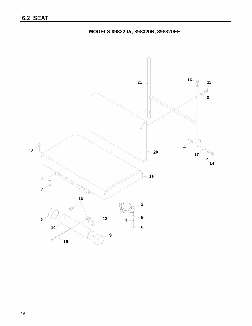
6.2 SEAT
16
MODELS 898320A, 898320B, 898320EE
1
2
3
4
5
6
7
8
9
10
11
12
13
14
15
16
17
18
19
20
21
9 1

SEAT 6.2
17
Ref.No.
PartNo. Description Notes
No.Req’d
1 120052 Lockwasher, #10 5. . . . . . . . . . . . . . . . . . . . . . . . . . . . . 2 158135-01 Switch, seat 1. . . . . . . . . . . . . . . . . . . . . . . . . . . . . . . . . 3 306396 Lockwasher, 1/4 3. . . . . . . . . . . . . . . . . . . . . . . . . . . . . 4 306423 Screw, 5/16–18 x 1 3/4 2. . . . . . . . . . . . . . . . . . . . . . . 5 306453 Washer, 5/16 2. . . . . . . . . . . . . . . . . . . . . . . . . . . . . . . . 6 306527 Screw, #10–24 x 3/4 PTH 2. . . . . . . . . . . . . . . . . . . . . 7 306531 Nut, #10–24 3. . . . . . . . . . . . . . . . . . . . . . . . . . . . . . . . . 8 308089 Washer, #10 2. . . . . . . . . . . . . . . . . . . . . . . . . . . . . . . . . 9 38061A Cap, vinyl 2. . . . . . . . . . . . . . . . . . . . . . . . . . . . . . . . . . . 10 38541 Tube, document 1. . . . . . . . . . . . . . . . . . . . . . . . . . . . . 11 600014 Screw, 1/4–20 x 1 3/4 4. . . . . . . . . . . . . . . . . . . . . . . . 12 800271 Screw, #10–24 x 1/2 PTH 3. . . . . . . . . . . . . . . . . . . . . 13 800344 Screw, #10–16 x 9/16 tapping 2. . . . . . . . . . . . . . . . . 14 800697 Nut, flangelock 5/16–18 2. . . . . . . . . . . . . . . . . . . . . . . 15 823549 Tie, wire 15.5″ (40mm) 2. . . . . . . . . . . . . . . . . . . . . . . 16 826747 Plug, hole 2. . . . . . . . . . . . . . . . . . . . . . . . . . . . . . . . . . . 17 840499 Bushing 2. . . . . . . . . . . . . . . . . . . . . . . . . . . . . . . . . . . . 18 840508 Mount, cable tie 2. . . . . . . . . . . . . . . . . . . . . . . . . . . . . . 19 883938 Seat 1. . . . . . . . . . . . . . . . . . . . . . . . . . . . . . . . . . . . . . . . 20 884683 Backrest 1. . . . . . . . . . . . . . . . . . . . . . . . . . . . . . . . . . . . 21 892823 Frame, backrest 1. . . . . . . . . . . . . . . . . . . . . . . . . . . . .
MODELS 898320A, 898320B, 898320EE
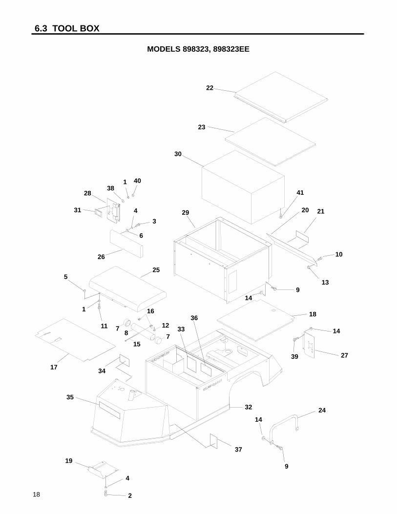
6.3 TOOL BOX
18
MODELS 898323, 898323EE
1
2
3
4
5
6
78
9
10
11 12
13
14
15
16
17
18
19
20 21
22
23
24
25
26
27
28
29
30
31
32
33
34
35
36
37
38
39
40
41
1
714
14
9
4
TOOL BOX 6.3
19
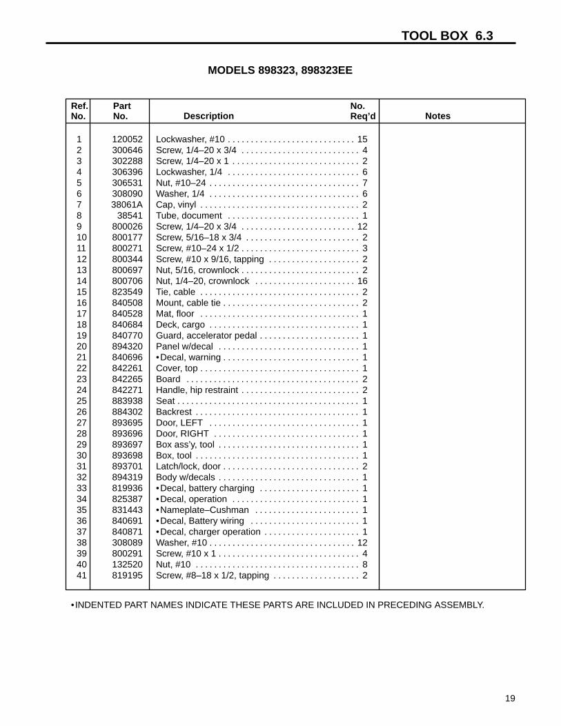
1 120052 Lockwasher, #10 15. . . . . . . . . . . . . . . . . . . . . . . . . . . . 2 300646 Screw, 1/4–20 x 3/4 4. . . . . . . . . . . . . . . . . . . . . . . . . . 3 302288 Screw, 1/4–20 x 1 2. . . . . . . . . . . . . . . . . . . . . . . . . . . . 4 306396 Lockwasher, 1/4 6. . . . . . . . . . . . . . . . . . . . . . . . . . . . . 5 306531 Nut, #10–24 7. . . . . . . . . . . . . . . . . . . . . . . . . . . . . . . . . 6 308090 Washer, 1/4 6. . . . . . . . . . . . . . . . . . . . . . . . . . . . . . . . . 7 38061A Cap, vinyl 2. . . . . . . . . . . . . . . . . . . . . . . . . . . . . . . . . . . 8 38541 Tube, document 1. . . . . . . . . . . . . . . . . . . . . . . . . . . . . 9 800026 Screw, 1/4–20 x 3/4 12. . . . . . . . . . . . . . . . . . . . . . . . . 10 800177 Screw, 5/16–18 x 3/4 2. . . . . . . . . . . . . . . . . . . . . . . . . 11 800271 Screw, #10–24 x 1/2 3. . . . . . . . . . . . . . . . . . . . . . . . . . 12 800344 Screw, #10 x 9/16, tapping 2. . . . . . . . . . . . . . . . . . . . 13 800697 Nut, 5/16, crownlock 2. . . . . . . . . . . . . . . . . . . . . . . . . . 14 800706 Nut, 1/4–20, crownlock 16. . . . . . . . . . . . . . . . . . . . . . 15 823549 Tie, cable 2. . . . . . . . . . . . . . . . . . . . . . . . . . . . . . . . . . . 16 840508 Mount, cable tie 2. . . . . . . . . . . . . . . . . . . . . . . . . . . . . . 17 840528 Mat, floor 1. . . . . . . . . . . . . . . . . . . . . . . . . . . . . . . . . . . 18 840684 Deck, cargo 1. . . . . . . . . . . . . . . . . . . . . . . . . . . . . . . . . 19 840770 Guard, accelerator pedal 1. . . . . . . . . . . . . . . . . . . . . . 20 894320 Panel w/decal 1. . . . . . . . . . . . . . . . . . . . . . . . . . . . . . . 21 840696 •Decal, warning 1. . . . . . . . . . . . . . . . . . . . . . . . . . . . . . 22 842261 Cover, top 1. . . . . . . . . . . . . . . . . . . . . . . . . . . . . . . . . . . 23 842265 Board 2. . . . . . . . . . . . . . . . . . . . . . . . . . . . . . . . . . . . . . 24 842271 Handle, hip restraint 2. . . . . . . . . . . . . . . . . . . . . . . . . . 25 883938 Seat 1. . . . . . . . . . . . . . . . . . . . . . . . . . . . . . . . . . . . . . . . 26 884302 Backrest 1. . . . . . . . . . . . . . . . . . . . . . . . . . . . . . . . . . . . 27 893695 Door, LEFT 1. . . . . . . . . . . . . . . . . . . . . . . . . . . . . . . . . 28 893696 Door, RIGHT 1. . . . . . . . . . . . . . . . . . . . . . . . . . . . . . . . 29 893697 Box ass’y, tool 1. . . . . . . . . . . . . . . . . . . . . . . . . . . . . . . 30 893698 Box, tool 1. . . . . . . . . . . . . . . . . . . . . . . . . . . . . . . . . . . . 31 893701 Latch/lock, door 2. . . . . . . . . . . . . . . . . . . . . . . . . . . . . . 32 894319 Body w/decals 1. . . . . . . . . . . . . . . . . . . . . . . . . . . . . . . 33 819936 •Decal, battery charging 1. . . . . . . . . . . . . . . . . . . . . . 34 825387 •Decal, operation 1. . . . . . . . . . . . . . . . . . . . . . . . . . . . 35 831443 •Nameplate–Cushman 1. . . . . . . . . . . . . . . . . . . . . . . 36 840691 •Decal, Battery wiring 1. . . . . . . . . . . . . . . . . . . . . . . . 37 840871 •Decal, charger operation 1. . . . . . . . . . . . . . . . . . . . . 38 308089 Washer, #10 12. . . . . . . . . . . . . . . . . . . . . . . . . . . . . . . . 39 800291 Screw, #10 x 1 4. . . . . . . . . . . . . . . . . . . . . . . . . . . . . . . 40 132520 Nut, #10 8. . . . . . . . . . . . . . . . . . . . . . . . . . . . . . . . . . . . 41 819195 Screw, #8–18 x 1/2, tapping 2. . . . . . . . . . . . . . . . . . .
Ref.No.
PartNo. Description Notes
No.Req’d
• INDENTED PART NAMES INDICATE THESE PARTS ARE INCLUDED IN PRECEDING ASSEMBLY.
MODELS 898323, 898323EE

6.4 BRAKE PEDAL & LINKAGE
20
1
2
3
4
5
6
7
8
9
10
11
12
13
14
15
16
17
18
19
20
21 22
23
24
25
26
27
2829
30
31
32
33
34
35
4
19
3
29
1
3
2
32
18
22 3
2010

BRAKE PEDAL & LINKAGE 6.4
21
Ref.No.
PartNo. Description Notes
No.Req’d
1 103867 Washer, 11/32 4. . . . . . . . . . . . . . . . . . . . . . . . . . . . . . . 2 120052 Lockwasher, #10 4. . . . . . . . . . . . . . . . . . . . . . . . . . . . . 3 306328 Pin, cotter 3/32 x 3/4 7. . . . . . . . . . . . . . . . . . . . . . . . . 4 2703903.7 Pivot, brake 1. . . . . . . . . . . . . . . . . . . . . . . . . . . . . . . . . 5 306320 Nut, 5/16–24 2. . . . . . . . . . . . . . . . . . . . . . . . . . . . . . . . 6 306391 Screw, #10–32 x 5/16 2. . . . . . . . . . . . . . . . . . . . . . . . 7 306435 Screw, 5/16–18 x 1 1/4 1. . . . . . . . . . . . . . . . . . . . . . . 8 306531 Nut, #10–24 2. . . . . . . . . . . . . . . . . . . . . . . . . . . . . . . . . 9 306932 Nut, 5/16–18 2. . . . . . . . . . . . . . . . . . . . . . . . . . . . . . . . 10 892802 Latch, brake 1. . . . . . . . . . . . . . . . . . . . . . . . . . . . . . . . . 11 308090 Washer, 1/4 1. . . . . . . . . . . . . . . . . . . . . . . . . . . . . . . . . 12 517163 Spacer 1. . . . . . . . . . . . . . . . . . . . . . . . . . . . . . . . . . . . . 13 800271 Screw, #10–24 x 1/2 2. . . . . . . . . . . . . . . . . . . . . . . . . 14 800557 Bolt, carriage 5/16–18 x 3/4 2. . . . . . . . . . . . . . . . . . . 15 800290 Nut, lock 5/16–18 1. . . . . . . . . . . . . . . . . . . . . . . . . . . . 16 800697 Nut, flangelock 5/16–18 2. . . . . . . . . . . . . . . . . . . . . . 17 800873 Washer, nylon 3/8 1. . . . . . . . . . . . . . . . . . . . . . . . . . . . 18 800874 Washer, 11/32 2. . . . . . . . . . . . . . . . . . . . . . . . . . . . . . . 19 806714 Pin, clevis 5/16 x 15/16 4. . . . . . . . . . . . . . . . . . . . . . . 20 810722 Yoke 2. . . . . . . . . . . . . . . . . . . . . . . . . . . . . . . . . . . . . . . 21 814005 Switch 1. . . . . . . . . . . . . . . . . . . . . . . . . . . . . . . . . . . . . . 22 806703 Pin, clevis 2. . . . . . . . . . . . . . . . . . . . . . . . . . . . . . . . . . 23 817507 Spring 1. . . . . . . . . . . . . . . . . . . . . . . . . . . . . . . . . . . . . . 24 822313 Spring, extension 1. . . . . . . . . . . . . . . . . . . . . . . . . . . . 25 829860 Spring 1. . . . . . . . . . . . . . . . . . . . . . . . . . . . . . . . . . . . . . 26 830661 Rod, threaded 1. . . . . . . . . . . . . . . . . . . . . . . . . . . . . . . 27 830784 Pin, pivot 1. . . . . . . . . . . . . . . . . . . . . . . . . . . . . . . . . . . 28 831861 Bolt, adjusting 1. . . . . . . . . . . . . . . . . . . . . . . . . . . . . . . 29 840326 Strape, brake 4. . . . . . . . . . . . . . . . . . . . . . . . . . . . . . . . 30 840335 Crossmember, brake 1. . . . . . . . . . . . . . . . . . . . . . . . . 31 840491 Bushing 1. . . . . . . . . . . . . . . . . . . . . . . . . . . . . . . . . . . . 32 840494 Bearing, flanged 3. . . . . . . . . . . . . . . . . . . . . . . . . . . . . 33 840666 Latch, brake lock 1. . . . . . . . . . . . . . . . . . . . . . . . . . . . . 34 840667 Latch, park brake 1. . . . . . . . . . . . . . . . . . . . . . . . . . . . 35 2703900.7 Arm, brake 1. . . . . . . . . . . . . . . . . . . . . . . . . . . . . . . . . .

6.5 SPEED CONTROL PEDAL (A & EARLIER B MODELS)
22
1
2
3
4
5
6
7
8
9
10
11
12
13
14
15
16
17
18
2
13 6
1
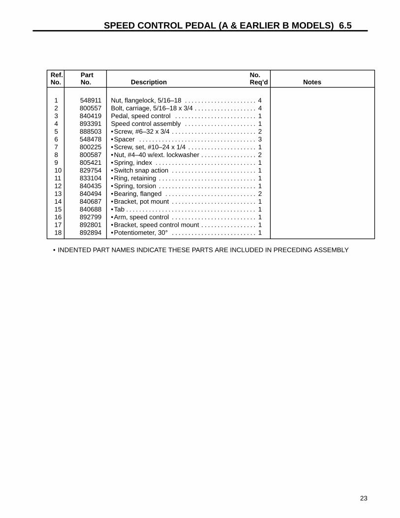
SPEED CONTROL PEDAL (A & EARLIER B MODELS) 6.5
23
Ref.No.
PartNo. Description Notes
No.Req’d
• INDENTED PART NAMES INDICATE THESE PARTS ARE INCLUDED IN PRECEDING ASSEMBLY
1 548911 Nut, flangelock, 5/16–18 4. . . . . . . . . . . . . . . . . . . . . . 2 800557 Bolt, carriage, 5/16–18 x 3/4 4. . . . . . . . . . . . . . . . . . . 3 840419 Pedal, speed control 1. . . . . . . . . . . . . . . . . . . . . . . . . 4 893391 Speed control assembly 1. . . . . . . . . . . . . . . . . . . . . . 5 888503 •Screw, #6–32 x 3/4 2. . . . . . . . . . . . . . . . . . . . . . . . . . 6 548478 •Spacer 3. . . . . . . . . . . . . . . . . . . . . . . . . . . . . . . . . . . . 7 800225 •Screw, set, #10–24 x 1/4 1. . . . . . . . . . . . . . . . . . . . . 8 800587 •Nut, #4–40 w/ext. lockwasher 2. . . . . . . . . . . . . . . . . 9 805421 •Spring, index 1. . . . . . . . . . . . . . . . . . . . . . . . . . . . . . . 10 829754 •Switch snap action 1. . . . . . . . . . . . . . . . . . . . . . . . . . 11 833104 •Ring, retaining 1. . . . . . . . . . . . . . . . . . . . . . . . . . . . . . 12 840435 •Spring, torsion 1. . . . . . . . . . . . . . . . . . . . . . . . . . . . . . 13 840494 •Bearing, flanged 2. . . . . . . . . . . . . . . . . . . . . . . . . . . . 14 840687 •Bracket, pot mount 1. . . . . . . . . . . . . . . . . . . . . . . . . . 15 840688 •Tab 1. . . . . . . . . . . . . . . . . . . . . . . . . . . . . . . . . . . . . . . . 16 892799 •Arm, speed control 1. . . . . . . . . . . . . . . . . . . . . . . . . . 17 892801 •Bracket, speed control mount 1. . . . . . . . . . . . . . . . . 18 892894 •Potentiometer, 30° 1. . . . . . . . . . . . . . . . . . . . . . . . . .
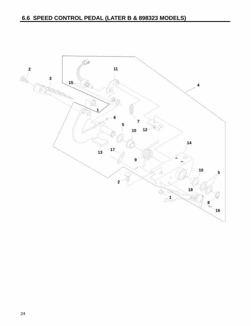
6.6 SPEED CONTROL PEDAL (LATER B & 898323 MODELS)
24
2
315
11
4
1
6
13
510
9
2
1
12
7
14
10 5
8
16
18
17

SPEED CONTROL PEDAL (LATER B & 898323 MODELS) 6.6
25
Ref.No.
PartNo. Description Notes
No.Req’d
• INDENTED PART NAMES INDICATE THESE PARTS ARE INCLUDED IN PRECEDING ASSEMBLY
1 548911 Nut, flangelock, 5/16–18 4. . . . . . . . . . . . . . . . . . . . . . 2 800557 Bolt, carriage, 5/16–18 x 3/4 4. . . . . . . . . . . . . . . . . . . 3 840419 Pedal, speed control 1. . . . . . . . . . . . . . . . . . . . . . . . . 4 894440 Speed control assembly 1. . . . . . . . . . . . . . . . . . . . . . 5 548478 •Spacer 3. . . . . . . . . . . . . . . . . . . . . . . . . . . . . . . . . . . . 6 800225 •Screw, set, #10–24 x 1/4 1. . . . . . . . . . . . . . . . . . . . . 7 805421 •Spring, index 1. . . . . . . . . . . . . . . . . . . . . . . . . . . . . . . 8 833104 •Ring, retaining 1. . . . . . . . . . . . . . . . . . . . . . . . . . . . . . 9 840435 •Spring, torsion 1. . . . . . . . . . . . . . . . . . . . . . . . . . . . . . 10 840494 •Bearing, flanged 2. . . . . . . . . . . . . . . . . . . . . . . . . . . . 11 869184 •Bracket, pot mount 1. . . . . . . . . . . . . . . . . . . . . . . . . . 12 840688 •Tab 1. . . . . . . . . . . . . . . . . . . . . . . . . . . . . . . . . . . . . . . . 13 897182 •Arm, speed control 1. . . . . . . . . . . . . . . . . . . . . . . . . . 14 897183 •Bracket, speed control mount 1. . . . . . . . . . . . . . . . . 15 894461 •Potentiometer, 30° 1. . . . . . . . . . . . . . . . . . . . . . . . . . 16 800897 •Screw, #4–40 2. . . . . . . . . . . . . . . . . . . . . . . . . . . . . . . 17 841151 •Nut, #4 tapping twin 1. . . . . . . . . . . . . . . . . . . . . . . . . 18 894439 •Switch, NC 1 Not used on these units.. . . . . . . . . . . . . . . . . . . . . . . . . . . . . . . . .
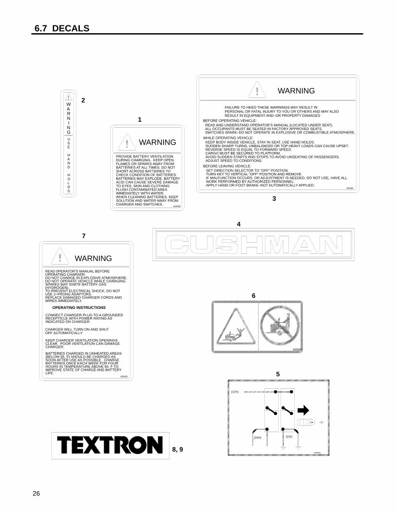
6.7 DECALS
26
WARNING
USE HAND HOLDS
WARNING
BEFORE LEAVING VEHICLE:SET DIRECTION SELECTOR TO ”OFF” POSITION.TURN KEY TO VERTICAL ”OFF” POSITION AND REMOVE.IF MALFUNCTION OCCURS, OR ADJUSTMENT IS NEEDED, DO NOT USE, HAVE ALLWORK PERFORMED BY AUTHORIZED PERSONNEL.APPLY HAND OR FOOT BRAKE–NOT AUTOMATICALLY APPLIED.
825387
KEEP BODY INSIDE VEHICLE, STAY IN SEAT, USE HAND HOLDS.SUDDEN SHARP TURNS, UNBALANCED OR TOP HEAVY LOADS CAN CAUSE UPSET.REVERSE SPEED IS EQUAL TO FORWARD SPEED.CARGO MUST BE SECURED TO PLATFORM.AVOID SUDDEN STARTS AND STOPS TO AVOID UNSEATING OF PASSENGERS.ADJUST SPEED TO CONDITIONS.
WHILE OPERATING VEHICLE:
READ AND UNDERSTAND OPERATOR’S MANUAL (LOCATED UNDER SEAT).ALL OCCUPANTS MUST BE SEATED IN FACTORY APPROVED SEATS.SWITCHES SPARK–DO NOT OPERATE IN EXPLOSIVE OR COMBUSTIBLE ATMOSPHERE.
BEFORE OPERATING VEHICLE:
FAILURE TO HEED THESE WARNINGS MAY RESULT INPERSONAL OR FATAL INJURY TO YOU OR OTHERS AND MAY ALSORESULT IN EQUIPMENT AND–OR PROPERTY DAMAGES
OPERATING INSTRUCTIONS
WARNING
KEEP CHARGER VENTILATION OPENINGSCLEAR. POOR VENTILATION CAN DAMAGECHARGER.
BATTERIES CHARGED IN UNHEATED AREAS(BELOW 65 F) SHOULD BE CHARGED ASSOON AFTER USE AS POSSIBLE. CHARGEBATTERIES ONCE EACH WEEK FOR FOURHOURS IN TEMPERATURE ABOVE 65 F TOIMPROVE STATE OF CHARGE AND BATTERYLIFE.
830926
READ 0PERATOR’S MANUAL BEFOREOPERATING CHARGER.DO NOT CHARGE IN EXPLOSIVE ATMOSPHERE.DO NOT OPERATE VEHICLE WHILE CHARGING.SPARKS MAY IGNITE BATTERY GAS(HYDROGEN).TO PREVENT ELECTRICAL SHOCK, DO NOTUSE 2–PRONG ADAPTORS.REPLACE DAMAGED CHARGER CORDS ANDWIRES IMMEDIATELY.
CONNECT CHARGER PLUG TO A GROUNDEDRECEPTICLE WITH POWER RATING ASINDICATED ON CHARGER.
WARNING
PROVIDE BATTERY VENTILATIONDURING CHARGING. KEEP OPENFLAMES OR SPARKS AWAY FROMBATTERIES AT ALL TIMES. DO NOTSHORT ACROSS BATTERIES TO CHECK CONDITION OF BATTERIES.BATTERIES MAY EXPLODE. BATTERYACID CAN CAUSE SEVERE DAMAGETO EYES, SKIN AND CLOTHING.FLUSH CONTAMINATED AREAIMMEDIATELY WITH WATER.WHEN CLEANING BATTERIES. KEEPSOLUTION AND WATER AWAY FROMCHARGER AND SWITCHES.
819936
CHARGER WILL TURN ON AND SHUTOFF AUTOMATICALLY
(12V)
(OV)(24V)
840691
840696
8, 9
1
2
3
4
5
6
7

DECALS 6.7
27
Ref.No.
PartNo. Description Notes
No.Req’d
1 819936 WARNING – battery vent 1. . . . . . . . . . . . . . . . . . . . . 2 825328 WARNING – use hand holds 2. . . . . . . . . . . . . . . . . . 3 825387 WARNING – vehicle op. 1. . . . . . . . . . . . . . . . . . . . . . 4 831443 Plate, CUSHMAN 1. . . . . . . . . . . . . . . . . . . . . . . . . . . . 5 840691 Battery wiring 1. . . . . . . . . . . . . . . . . . . . . . . . . . . . . . . . 6 840696 WARNING – no standing 1. . . . . . . . . . . . . . . . . . . . . . 7 840871 WARNING – charger op. 1. . . . . . . . . . . . . . . . . . . . . . 8 841860 Plate, TEXTRON 4” 1. . . . . . . . . . . . . . . . . . . . . . . . . . 9 844847 Decal, TEXTRON 1. . . . . . . . . . . . . . . . . . . . . . . . . . . .

6.8 FORK, HUB & HANDLEBARS
28
38
1
2
3
5
6
7
8
9
10
11
12
13
14
15
16 19
2021
22
23
24
25
26
27
28
29
3031
32
33
34
35
3637
4
18
32
3736
32
29
17
34
38
39

FORK, HUB & HANDLEBARS 6.8
29
1 120166 Lockwasher, 1/2 1. . . . . . . . . . . . . . . . . . . . . . . . . . . . . 2 301988 Nut, 1/2–20 1. . . . . . . . . . . . . . . . . . . . . . . . . . . . . . . . . 3 305134 Nut, jam 7/8–14 2. . . . . . . . . . . . . . . . . . . . . . . . . . . . . 4 520231 Washer, thrust 1 1/4 1. . . . . . . . . . . . . . . . . . . . . . . . . . 5 551041 Key, woodruff #6 1. . . . . . . . . . . . . . . . . . . . . . . . . . . . . 6 800144 Screw, #10–16 x 5/8 PTH 2. . . . . . . . . . . . . . . . . . . . . 7 800500 Bolt, carriage 3/8–16 x 1 4. . . . . . . . . . . . . . . . . . . . . . 8 800573 Nut, lug 1/2–20 4. . . . . . . . . . . . . . . . . . . . . . . . . . . . . . 9 800610 Screw, flange 7/16–20 x 1 1/8 2. . . . . . . . . . . . . . . . . 10 800612 Nut, lock 7/16–20 2. . . . . . . . . . . . . . . . . . . . . . . . . . . . 11 806791 Horn Button 1. . . . . . . . . . . . . . . . . . . . . . . . . . . . . . . . . 12 800698 Nut, flangelock 3/8–16 4. . . . . . . . . . . . . . . . . . . . . . . . 13 807290 Insulator, horn 1. . . . . . . . . . . . . . . . . . . . . . . . . . . . . . . 14 807472 Grip, handle 2. . . . . . . . . . . . . . . . . . . . . . . . . . . . . . . . . 15 831909 Boot 1. . . . . . . . . . . . . . . . . . . . . . . . . . . . . . . . . . . . . . . . 16 840318 Clamp, half 2. . . . . . . . . . . . . . . . . . . . . . . . . . . . . . . . . . 17 840324 Bearing, flanged 2. . . . . . . . . . . . . . . . . . . . . . . . . . . . . 18 840372 Washer, rubber 1. . . . . . . . . . . . . . . . . . . . . . . . . . . . . . 19 840411 Nut, spindle 1. . . . . . . . . . . . . . . . . . . . . . . . . . . . . . . . . 20 840412 Washer, 7/16 2. . . . . . . . . . . . . . . . . . . . . . . . . . . . . . . . 21 840458 Ring, V 1. . . . . . . . . . . . . . . . . . . . . . . . . . . . . . . . . . . . . 22 840479 Bracket, fork RH 1. . . . . . . . . . . . . . . . . . . . . . . . . . . . . 23 840689 Bracket, fork LH 1. . . . . . . . . . . . . . . . . . . . . . . . . . . . . 24 892668 Wheel Assembly 1. . . . . . . . . . . . . . . . . . . . . . . . . . . . .
•Tire, 4.80 x 8 load range B 1 Obtain locally. Not illustrated.. . . . . . . . . . . . . . . . . . . 840843 •Rim, wheel 1 Not illustrated.. . . . . . . . . . . . . . . . . . . . . . . . . . . . . . . . . 886735 •Valve Stem 1 Not illustrated.. . . . . . . . . . . . . . . . . . . . . . . . . . . . . . . . .
25 892701 Fork 1. . . . . . . . . . . . . . . . . . . . . . . . . . . . . . . . . . . . . . . . 26 892744 Mount, suspension 2. . . . . . . . . . . . . . . . . . . . . . . . . . . 27 892764 Handle Bar 1. . . . . . . . . . . . . . . . . . . . . . . . . . . . . . . . . . 28 892781 Axle & Hub Assembly 1. . . . . . . . . . . . . . . . . . . . . . . . 29 130084 •Nut, 5/8–18 2. . . . . . . . . . . . . . . . . . . . . . . . . . . . . . . . 30 310854 •Nut, jam 1–14 1. . . . . . . . . . . . . . . . . . . . . . . . . . . . . . 31 815814 •Nut, bearing adjusting 1. . . . . . . . . . . . . . . . . . . . . . . 32 809156 •Washer, thrust 9/16 4. . . . . . . . . . . . . . . . . . . . . . . . . 33 840325 •Axle 1. . . . . . . . . . . . . . . . . . . . . . . . . . . . . . . . . . . . . . . 34 306494 •Lockwasher, 5/8 2. . . . . . . . . . . . . . . . . . . . . . . . . . . . 35 892751 •Hub Assembly 1. . . . . . . . . . . . . . . . . . . . . . . . . . . . . . 36 700290 •• Seal, grease 2. . . . . . . . . . . . . . . . . . . . . . . . . . . . . . . 37 814473 •• Bearing 2. . . . . . . . . . . . . . . . . . . . . . . . . . . . . . . . . . . 38 814474 •• Race, bearing 2. . . . . . . . . . . . . . . . . . . . . . . . . . . . . 39 843616 •• Bolt, wheel 4. . . . . . . . . . . . . . . . . . . . . . . . . . . . . . . .
Ref.No.
PartNo. Description Notes
No.Req’d
• INDENTED PART NAMES INDICATE THESE PARTS ARE INCLUDED IN PRECEDING ASSEMBLY

6.9 DIFFERENTIAL
30
FRONT OFVEHICLE
♦♦ ♦♦ ♦♦
♦♦ Not Available Separately
2530
2631
2328
2429
2227
33
32
34
35
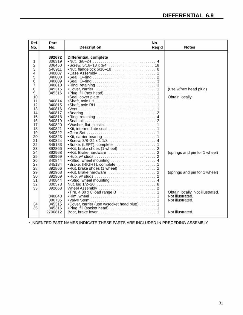
DIFFERENTIAL 6.9
31
Ref.No.
PartNo. Description Notes
No.Req’d
• INDENTED PART NAMES INDICATE THESE PARTS ARE INCLUDED IN PRECEDING ASSEMBLY
892672 Differential, complete1 306319 •Nut, 3/8–24 4. . . . . . . . . . . . . . . . . . . . . . . . . . . . . . . . 2 306450 •Screw, 5/16–18 x 3/4 18. . . . . . . . . . . . . . . . . . . . . . . 3 548911 •Nut, flangelock 5/16–18 8. . . . . . . . . . . . . . . . . . . . . . 4 840807 •Case Assembly 1. . . . . . . . . . . . . . . . . . . . . . . . . . . . . 5 840808 •Seal, O–ring 2. . . . . . . . . . . . . . . . . . . . . . . . . . . . . . . . 6 840809 •Seal, O–ring 3. . . . . . . . . . . . . . . . . . . . . . . . . . . . . . . . 7 840810 •Ring, retaining 3. . . . . . . . . . . . . . . . . . . . . . . . . . . . . . 8 845315 •Cover, carrier 1 (use w/hex head plug). . . . . . . . . . . . . . . . . . . . . . . . . . . . . . . 9 845316 •Plug, fill (hex head) 1. . . . . . . . . . . . . . . . . . . . . . . . . . 10 •Seal, cover plate 1 Obtain locally.. . . . . . . . . . . . . . . . . . . . . . . . . . . . 11 840814 •Shaft, axle LH 1. . . . . . . . . . . . . . . . . . . . . . . . . . . . . . 12 840815 •Shaft, axle RH 1. . . . . . . . . . . . . . . . . . . . . . . . . . . . . . 13 840816 •Vent 1. . . . . . . . . . . . . . . . . . . . . . . . . . . . . . . . . . . . . . . 14 840817 •Bearing 2. . . . . . . . . . . . . . . . . . . . . . . . . . . . . . . . . . . . 15 840818 •Ring, retaining 4. . . . . . . . . . . . . . . . . . . . . . . . . . . . . . 16 840819 •Seal, oil 2. . . . . . . . . . . . . . . . . . . . . . . . . . . . . . . . . . . . 17 840820 •Washer, flat plastic 1. . . . . . . . . . . . . . . . . . . . . . . . . 18 840821 •Kit, intermediate seal 1. . . . . . . . . . . . . . . . . . . . . . . . 19 840822 •Gear Set 1. . . . . . . . . . . . . . . . . . . . . . . . . . . . . . . . . . . 20 840823 •Kit, carrier bearing 1. . . . . . . . . . . . . . . . . . . . . . . . . . 21 840824 •Screw, 3/8–24 x 1 1/8 4. . . . . . . . . . . . . . . . . . . . . . . 22 845183 •Brake, (LEFT), complete 1. . . . . . . . . . . . . . . . . . . . . 23 892866 •• Kit, brake shoes (1 wheel) 2. . . . . . . . . . . . . . . . . . . 24 892968 •• Kit, Brake hardware 2 (springs and pin for 1 wheel). . . . . . . . . . . . . . . . . . . . . . . . 25 892969 •Hub, w/ studs 2. . . . . . . . . . . . . . . . . . . . . . . . . . . . . . . 26 840844 •• Stud, wheel mounting 4. . . . . . . . . . . . . . . . . . . . . . . 27 845184 •Brake, (RIGHT), complete 1. . . . . . . . . . . . . . . . . . . . 28 892866 •• Kit, brake shoes (1 wheel) 2. . . . . . . . . . . . . . . . . . . 29 892968 •• Kit, Brake hardware 2 (springs and pin for 1 wheel). . . . . . . . . . . . . . . . . . . . . . . . 30 892969 •Hub, w/ studs 2. . . . . . . . . . . . . . . . . . . . . . . . . . . . . . . 31 840844 •• Stud, wheel mounting 4. . . . . . . . . . . . . . . . . . . . . . . 32 800573 Nut, lug 1/2–20 8. . . . . . . . . . . . . . . . . . . . . . . . . . . . . . 33 892668 Wheel Assembly 2. . . . . . . . . . . . . . . . . . . . . . . . . . . . .
•Tire, 4.80 x 8 load range B 1 Obtain locally. Not illustrated.. . . . . . . . . . . . . . . . . . . 840843 •Rim, wheel 1 Not illustrated.. . . . . . . . . . . . . . . . . . . . . . . . . . . . . . . . . 886735 •Valve Stem 1 Not illustrated.. . . . . . . . . . . . . . . . . . . . . . . . . . . . . . . . .
34 845315 •Cover, carrier (use w/socket head plug) 1. . . . . . . . 35 845316 •Plug, fill (socket head) 1. . . . . . . . . . . . . . . . . . . . . . .
2700812 Boot, brake lever 1 Not illustrated.. . . . . . . . . . . . . . . . . . . . . . . . . . . . .

6.10 ELECTRICAL COMPONENTS
32
Ground wire from main harness
1
2
3
4
5
6
7
8
9
10
11
1213
14
15
16
17
18
19
20
21
22
23
25
26
27
28
29
30
31
32
33
34 38
39
40
41
42
43
44
45
46
47
48
49
50
51
52
53
54
55
56
57 58
59
60 35
36
37
64
24
16
2
13
19
2
13
213
16
62
61
63
16
5
5
15
16
98
98
15
67
15
5
65
66
67

ELECTRICAL COMPONENTS 6.10
33
Ref.No.
PartNo. Description Notes
No.Req’d
• INDENTED PART NAMES INDICATE THESE PARTS ARE INCLUDED IN PRECEDING ASSEMBLY
1 103867 Washer, 5/16 8. . . . . . . . . . . . . . . . . . . . . . . . . . . . . . . . 2 120052 Washer, #10 7. . . . . . . . . . . . . . . . . . . . . . . . . . . . . . . . . 3 300646 Screw, 1/4–20 x 3/4 2. . . . . . . . . . . . . . . . . . . . . . . . . . 4 838769 Terminal, socket As Req’d.. . . . . . . . . . . . . . . . . . . . . 5 302288 Screw, 1/4–20 x 1 14. . . . . . . . . . . . . . . . . . . . . . . . . . . 6 306320 Nut, 5/16–24 12. . . . . . . . . . . . . . . . . . . . . . . . . . . . . . . 7 306325 Lockwasher, 5/16 4. . . . . . . . . . . . . . . . . . . . . . . . . . . . 8 306375 Nut, 1/4–20 8. . . . . . . . . . . . . . . . . . . . . . . . . . . . . . . . . 9 306396 Lockwasher, 1/4 7. . . . . . . . . . . . . . . . . . . . . . . . . . . . . 10 306419 Screw, 1/4–20 x 1/2 1. . . . . . . . . . . . . . . . . . . . . . . . . . 11 306450 Screw, 5/16–18 x 3/4 4. . . . . . . . . . . . . . . . . . . . . . . . . 12 306514 Screw, #10–24 x 1/2 slotted 2. . . . . . . . . . . . . . . . . . . 13 306531 Nut, #10–24 6. . . . . . . . . . . . . . . . . . . . . . . . . . . . . . . . . 14 306932 Nut, 5/16–18 4. . . . . . . . . . . . . . . . . . . . . . . . . . . . . . . . 15 308090 Washer, 1/4 6. . . . . . . . . . . . . . . . . . . . . . . . . . . . . . . . . 16 548910 Nut, 1/4–20 flangelock 6. . . . . . . . . . . . . . . . . . . . . . . . 17 800017 Screw, 1/4–20 x 1 PTH 1. . . . . . . . . . . . . . . . . . . . . . . 18 800271 Screw, #10–24 x 1/2 PTH 2. . . . . . . . . . . . . . . . . . . . . 19 800299 Screw, #10–24 x 1 PTH 3. . . . . . . . . . . . . . . . . . . . . . . 20 800587 Nut, #4–40 w/lockwasher 2. . . . . . . . . . . . . . . . . . . . . 21 814924 Clamp 3. . . . . . . . . . . . . . . . . . . . . . . . . . . . . . . . . . . . . . 22 817719 Bushing, fiber 2. . . . . . . . . . . . . . . . . . . . . . . . . . . . . . . 23 825880 Connector, 1 contact plug As Req’d.. . . . . . . . . . . . . 24 825884 Clamp 1. . . . . . . . . . . . . . . . . . . . . . . . . . . . . . . . . . . . . . 25 826005 Connector, 2 contact plug As Req’d.. . . . . . . . . . . . . 26 826006 Connector, 2 contact receptacle As Req’d.. . . . . . . . 27 826726 Connector, 1 contact receptacle As Req’d.. . . . . . . . 28 829164 Circuit Breaker, 90 amp 1. . . . . . . . . . . . . . . . . . . . . . . 29 829780 Circuit Breaker, 20 amp 1. . . . . . . . . . . . . . . . . . . . . . . 30 830640 Switch, rocker 1. . . . . . . . . . . . . . . . . . . . . . . . . . . . . . . 31 2703735 Relay, 30 amp 1 A models ONLY.. . . . . . . . . . . . . . . . . . . . . . . . . . . . . . . 32 835481 Plug, 30 amp 1 A models ONLY.. . . . . . . . . . . . . . . . . . . . . . . . . . . . . . . . 33 836354 Switch 1. . . . . . . . . . . . . . . . . . . . . . . . . . . . . . . . . . . . . . 34 839917 Plug, 2–wire As Req’d.. . . . . . . . . . . . . . . . . . . . . . . . .

6.10 ELECTRICAL COMPONENTS
34
Ground wire from main harness
1
2
3
4
5
6
7
8
9
10
11
1213
14
15
16
17
18
19
20
21
22
23
25
26
27
28
29
30
31
32
33
34 38
39
40
41
42
43
44
45
46
47
48
49
50
51
52
53
54
55
56
57 58
59
60 35
36
37
64
24
16
2
13
19
2
13
213
16
62
61
63
16
5
5
15
16
98
98
15
67
15
5
65
66
67

ELECTRICAL COMPONENTS 6.10
35
35 839918 Receptacle, 2–wire As Req’d.. . . . . . . . . . . . . . . . . . . 36 839921 Lock, 2–wire plug As Req’d.. . . . . . . . . . . . . . . . . . . . 37 839935 Lock, 2–wire receptacle As Req’d.. . . . . . . . . . . . . . . 38 839849 Plug, 3–wire As Req’d.. . . . . . . . . . . . . . . . . . . . . . . . . 39 839850 Receptacle, 3–wire As Req’d.. . . . . . . . . . . . . . . . . . . 40 840117 Lock, 3–wire receptacle As Req’d.. . . . . . . . . . . . . . . 41 840118 Lock, 3–wire plug As Req’d.. . . . . . . . . . . . . . . . . . . . 42 840273 Bar, solenoid bus 2. . . . . . . . . . . . . . . . . . . . . . . . . . . . 43 840491 Bushing 4. . . . . . . . . . . . . . . . . . . . . . . . . . . . . . . . . . . . 44 840496 Panel, control 1. . . . . . . . . . . . . . . . . . . . . . . . . . . . . . . 45 840526 Gauge, battery condition 1. . . . . . . . . . . . . . . . . . . . . . 46 2701550 Switch, reversing 1 A models ONLY.. . . . . . . . . . . . . . . . . . . . . . . . . . . . 47 840679 Rectifier bridge 1. . . . . . . . . . . . . . . . . . . . . . . . . . . . . . 48 841208 Solenoid, 24 volt 1. . . . . . . . . . . . . . . . . . . . . . . . . . . . . 49 841248 Solenoid, 24 volt 2. . . . . . . . . . . . . . . . . . . . . . . . . . . . . 50 886090 Horn 1. . . . . . . . . . . . . . . . . . . . . . . . . . . . . . . . . . . . . . . 51 829694 •Bracket, horn 1. . . . . . . . . . . . . . . . . . . . . . . . . . . . . . . 52 880631 Hour Meter Set (accessory) 1. . . . . . . . . . . . . . . . . . . 53 886311 Switch, ignition 1 Key not offered separately.. . . . . . . . . . . . . . . . . . . . . . . . . . . . . . 54 888503 Service Set contains two #4–40 x 3/4 screws 1. . . . 55 890000 Buzzer 1. . . . . . . . . . . . . . . . . . . . . . . . . . . . . . . . . . . . . 56 524358 Terminal, male pin (16–18 gauge) As Req’d.. . . . . . 57 892676 Light, red (tail light) 1. . . . . . . . . . . . . . . . . . . . . . . . . . . 58 892789 Controller, speed 1. . . . . . . . . . . . . . . . . . . . . . . . . . . . . 59 892942 Headlight Set (accessory) 1. . . . . . . . . . . . . . . . . . . . . 60 840854 •Bracket, headlight 1. . . . . . . . . . . . . . . . . . . . . . . . . . . 61 892523 •Headlight 1. . . . . . . . . . . . . . . . . . . . . . . . . . . . . . . . . . 62 840860 •• Bulb, headlight 1. . . . . . . . . . . . . . . . . . . . . . . . . . . . . 63 893142 Resistor, 250 ohm 1. . . . . . . . . . . . . . . . . . . . . . . . . . . . 64 894222 Switch, ignition, keyed alike 1 Key not offered separately.. . . . . . . . . . . . . . . . . . . 65 840676 Terminal, male pin (14–16 gauge) As Req’d.. . . . . . 66 825886 Terminal, 1/4 female, 14–16awg As Req’d. Not illustrated.. . . . . . . 67 825748 Terminal, 1/4 female, 14–16awg As Req’d. Not illustrated.. . . . . . .
845050 Grease, electrical connector 1 Not illustrated.. . . . . . . . . . . . . . . . . . .
Ref.No.
PartNo. Description Notes
No.Req’d
• INDENTED PART NAMES INDICATE THESE PARTS ARE INCLUDED IN PRECEDING ASSEMBLY

6.11 MOTOR (G.E.)
36
MOTOR 892671G.E. NO. 5BC58JBS6217
1
2
3
45
67
8
9
10
11 12
13
14
15
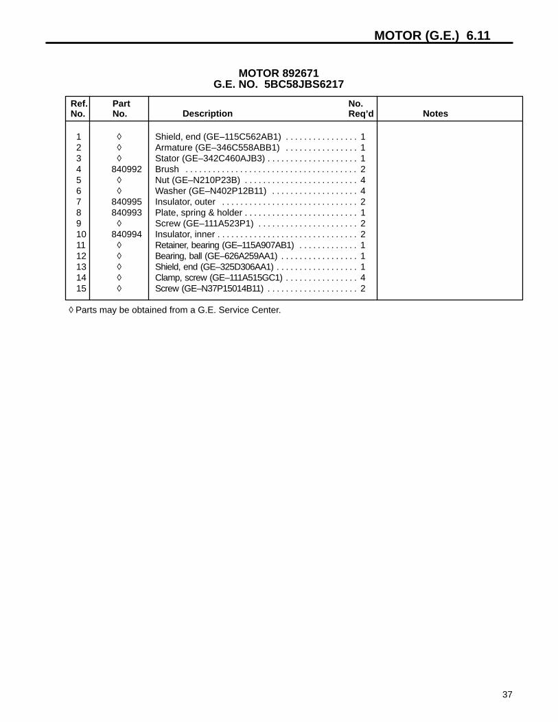
MOTOR (G.E.) 6.11
37
Ref.No.
PartNo. Description Notes
No.Req’d
1 ◊ Shield, end (GE–115C562AB1) 1. . . . . . . . . . . . . . . . 2 ◊ Armature (GE–346C558ABB1) 1. . . . . . . . . . . . . . . . 3 ◊ Stator (GE–342C460AJB3) 1. . . . . . . . . . . . . . . . . . . . 4 840992 Brush 2. . . . . . . . . . . . . . . . . . . . . . . . . . . . . . . . . . . . . . 5 ◊ Nut (GE–N210P23B) 4. . . . . . . . . . . . . . . . . . . . . . . . . 6 ◊ Washer (GE–N402P12B11) 4. . . . . . . . . . . . . . . . . . . 7 840995 Insulator, outer 2. . . . . . . . . . . . . . . . . . . . . . . . . . . . . . 8 840993 Plate, spring & holder 1. . . . . . . . . . . . . . . . . . . . . . . . . 9 ◊ Screw (GE–111A523P1) 2. . . . . . . . . . . . . . . . . . . . . . 10 840994 Insulator, inner 2. . . . . . . . . . . . . . . . . . . . . . . . . . . . . . . 11 ◊ Retainer, bearing (GE–115A907AB1) 1. . . . . . . . . . . . . 12 ◊ Bearing, ball (GE–626A259AA1) 1. . . . . . . . . . . . . . . . . 13 ◊ Shield, end (GE–325D306AA1) 1. . . . . . . . . . . . . . . . . . 14 ◊ Clamp, screw (GE–111A515GC1) 4. . . . . . . . . . . . . . . . 15 ◊ Screw (GE–N37P15014B11) 2. . . . . . . . . . . . . . . . . . . .
◊ Parts may be obtained from a G.E. Service Center.
MOTOR 892671G.E. NO. 5BC58JBS6217

6.12 MOTOR (ADVANCED DC)
38
1
2
3
4
56 7
89 10
ADVANCED DCPART NO. 73124–G02
orPART NO. 2703784

MOTOR (ADVANCED DC) 6.12
39
Ref.No.
PartNo. Description Notes
No.Req’d
73124–G02 Motor, non–vented 1. . . . . . . . . . . . . . . . . . . . . . . . . . . 1 •Armature 1 Not available individually.. . . . . . . . . . . . . . . . . . . . . . . . . . . . . . . . . . . 2 73120–G11 •Field coil kit 1 Includes hardware.. . . . . . . . . . . . . . . . . . . . . . . . . . . . . . . . 3 73120–G03 •Brush spring 4. . . . . . . . . . . . . . . . . . . . . . . . . . . . . . . . 4 73120–G15 •Brush plate and box 1. . . . . . . . . . . . . . . . . . . . . . . . . 5 73120–G05 •Brush replacement kit 1 Includes hardware.. . . . . . . . . . . . . . . . . . . . . . . 6 73120–G06 •Snap ring 1. . . . . . . . . . . . . . . . . . . . . . . . . . . . . . . . . . 7 73120–G07 •Bearing 1. . . . . . . . . . . . . . . . . . . . . . . . . . . . . . . . . . . . 8 73120–G08 •Cover communtator end 1. . . . . . . . . . . . . . . . . . . . . 9 73120–G09 •Cover plate and screw 1. . . . . . . . . . . . . . . . . . . . . . . 10 73120–G10 •Cap 1. . . . . . . . . . . . . . . . . . . . . . . . . . . . . . . . . . . . . . .
• INDENTED PART NAMES INDICATE THESE PARTS ARE INCLUDED IN PRECEDING ASSEMBLY
ADVANCED DCPART NO. 73124–G02
orPART NO. 2703784

6.13 STEERING WHEEL ACCESSORY
40
REF. FORK SPINDLE
REF. SPINDLETUBE BRACE
FRONT OFVEHICLE
2413
8
27
1517
10
6
2
6
32
33
3136
34
22
30
16
18
23
29
21
28
16
12
1
19
39
38
37
25
4
40
35
26
1211
7
12
19
1
12
14
5
3
20
6
5
ATTACH HORNBUTTON
15
17
4141
417

STEERING WHEEL ACCESSORY 6.13
41
893079 Accessory, steering wheel 1. . . . . . . . . . . . . . . . . . . . . 1 120177 •Lockwasher, 3/8 8. . . . . . . . . . . . . . . . . . . . . . . . . . . . 2 302030 •Screw, 1/4–20 x 1 1/4 3. . . . . . . . . . . . . . . . . . . . . . . 3 302288 •Screw, 1/4–20 x 1 4. . . . . . . . . . . . . . . . . . . . . . . . . . . 4 306367 •Key, woodruff .188 x .750 2. . . . . . . . . . . . . . . . . . . . 5 306375 •Nut, 1/4–20 8. . . . . . . . . . . . . . . . . . . . . . . . . . . . . . . . 6 306396 •Lockwasher, 1/4 11. . . . . . . . . . . . . . . . . . . . . . . . . . . 7 306414 •Screw, 3/8–16 x 1 3. . . . . . . . . . . . . . . . . . . . . . . . . . . 8 306487 •Screw, 1/4–20 x .62 4. . . . . . . . . . . . . . . . . . . . . . . . . 9 306562 •Nut, 3/8–16 3. . . . . . . . . . . . . . . . . . . . . . . . . . . . . . . . 10 306832 •Screw, 1/4–20 x 2 4. . . . . . . . . . . . . . . . . . . . . . . . . . . 11 302600 •Screw, 3/8–16 x 1 1/2 3. . . . . . . . . . . . . . . . . . . . . . . 12 306981 •Washer, 3/8 11. . . . . . . . . . . . . . . . . . . . . . . . . . . . . . . 13 311496 •Washer, 5/8 1. . . . . . . . . . . . . . . . . . . . . . . . . . . . . . . . 14 517663 •Washer 1. . . . . . . . . . . . . . . . . . . . . . . . . . . . . . . . . . . . 15 800612 •Nut, 7/16 crown lock 2. . . . . . . . . . . . . . . . . . . . . . . . . 16 816446 •Washer 2. . . . . . . . . . . . . . . . . . . . . . . . . . . . . . . . . . . . 17 816449 •Washer, locating 2. . . . . . . . . . . . . . . . . . . . . . . . . . . . 18 816652 •Nut, steering wheel 1. . . . . . . . . . . . . . . . . . . . . . . . . . 19 306834 •Screw, 3/8–16 x 3/4 2. . . . . . . . . . . . . . . . . . . . . . . . . 20 825672 •Nut 1. . . . . . . . . . . . . . . . . . . . . . . . . . . . . . . . . . . . . . . . 21 825919 •Plug, hole 1. . . . . . . . . . . . . . . . . . . . . . . . . . . . . . . . . . 22 830168 •Gear, cluster 1. . . . . . . . . . . . . . . . . . . . . . . . . . . . . . . 23 832555 •Housing, upper 1. . . . . . . . . . . . . . . . . . . . . . . . . . . . . 24 840017 •Cover, steering wheel center 1. . . . . . . . . . . . . . . . . 25 840981 •Shaft, steering wheel 1. . . . . . . . . . . . . . . . . . . . . . . . 26 840982 •Support, steering 2. . . . . . . . . . . . . . . . . . . . . . . . . . . 27 840983 •Cover, steering 1. . . . . . . . . . . . . . . . . . . . . . . . . . . . . 28 883317 •Bolt, idler adjusting 1. . . . . . . . . . . . . . . . . . . . . . . . . . 29 886883 •Housing, lower 1. . . . . . . . . . . . . . . . . . . . . . . . . . . . . . 30 886913 •Gear, driven 1. . . . . . . . . . . . . . . . . . . . . . . . . . . . . . . . 31 310546 •• Pin, roll 1/2 x 1 1/2 1. . . . . . . . . . . . . . . . . . . . . . . . . 32 816447 •Ring, internal retaining 1. . . . . . . . . . . . . . . . . . . . . . . 33 816455 •Ring, retaining 1. . . . . . . . . . . . . . . . . . . . . . . . . . . . . . 34 816456 •Bearing, ball 1. . . . . . . . . . . . . . . . . . . . . . . . . . . . . . . 35 837855 •Shaft, pinion gear 1. . . . . . . . . . . . . . . . . . . . . . . . . . . 36 891597 •Bushing, steering 1. . . . . . . . . . . . . . . . . . . . . . . . . . . 37 548225 •• Fitting, lube 1. . . . . . . . . . . . . . . . . . . . . . . . . . . . . . . 38 827188 •• Bearing 1. . . . . . . . . . . . . . . . . . . . . . . . . . . . . . . . . . . 39 891680 •Joint, universal 1. . . . . . . . . . . . . . . . . . . . . . . . . . . . . 40 892228 •Wheel, steering 14” 1. . . . . . . . . . . . . . . . . . . . . . . . . 41 808935 •Spacer 3. . . . . . . . . . . . . . . . . . . . . . . . . . . . . . . . . . . .
Ref.No.
PartNo. Description Notes
No.Req’d
• INDENTED PART NAMES INDICATE THESE PARTS ARE INCLUDED IN PRECEDING ASSEMBLY.

6.14 BATTERY CHARGER
42
NOTE: ILLUSTRATION FOR REFERENCE ONLY.
25 AMP, 115 VAC, 60 HZ
PART NO. 892860LESTER MODEL 16940
1
23
4
5
6
7
8
9
10
11
12
13
14

BATTERY CHARGER 6.14
43
Ref.No.
PartNo. Description Notes
No.Req’d
1 800017 Screw, 1/4–20 x 1 4. . . . . . . . . . . . . . . . . . . . . . . . . . . . 2 308090 Washer, 1/4 4. . . . . . . . . . . . . . . . . . . . . . . . . . . . . . . . . 3 306396 Lockwasher, 1/4 4. . . . . . . . . . . . . . . . . . . . . . . . . . . . . 4 306375 Nut, 1/4–20 4. . . . . . . . . . . . . . . . . . . . . . . . . . . . . . . . . 5 892860 Charger, complete, Model 16940 1. . . . . . . . . . . . . . . 6 892889 •Case, Lester No. 21559S 1. . . . . . . . . . . . . . . . . . . . 7 892890 •Transformer, Lester No. 16945S 1. . . . . . . . . . . . . . 8 886435 •Heatsink, w/diodes 1. . . . . . . . . . . . . . . . . . . . . . . . . . 9 892893 •• Relay 1. . . . . . . . . . . . . . . . . . . . . . . . . . . . . . . . . . . . . 10 892891 •Timer 1. . . . . . . . . . . . . . . . . . . . . . . . . . . . . . . . . . . . . . 11 823749 •Capacitor, 6.0 Mfd. 1. . . . . . . . . . . . . . . . . . . . . . . . . 12 822048 •Bushing, A.C. cord 1. . . . . . . . . . . . . . . . . . . . . . . . . . 13 883216 •Cordset, A.C. 1. . . . . . . . . . . . . . . . . . . . . . . . . . . . . .
892892 •Wiring harness 1 Not illustrated.. . . . . . . . . . . . . . . . . . . . . . . . . . . . . 14 883844 •Fuse 1. . . . . . . . . . . . . . . . . . . . . . . . . . . . . . . . . . . . . .
• INDENTED PART NAMES INDICATE THESE PARTS ARE INCLUDED IN PRECEDING ASSEMBLY.
25 AMP, 115 VAC, 60 HZ
PART NO. 892860LESTER MODEL 16940

6.15 EE COMPONENTS
44
REF. CIRCUIT BREAKERREF. MAIN SOLENOID
REF. MOTOR
REF. BODY
REF. FORK
REF. BODY
REF. TAIL LIGHT
REF.ADJUSTINGBOLT
REF. SEAT
3
17
13
8
126
16
16
16
1616
16
11
14
4
14
1
9
2
5
5
15
2
710
18
18
REF. FORWARDSOLENOID
REF. REVERSESOLENOID
16
16

EE COMPONENTS 6.15
45
1 120052 Lockwasher, #10 4. . . . . . . . . . . . . . . . . . . . . . . . . . . . . 2 2701213 Decal, EE 2. . . . . . . . . . . . . . . . . . . . . . . . . . . . . . . . . . . 3 2702875.7 Cover, headlight guard 1. . . . . . . . . . . . . . . . . . . . . . . . 4 2702915 Strap, static 1. . . . . . . . . . . . . . . . . . . . . . . . . . . . . . . . . 5 2702994 Hasp, safety w/staple 1. . . . . . . . . . . . . . . . . . . . . . . . . 6 2703038.7 Base, headllight guard 1. . . . . . . . . . . . . . . . . . . . . . . . 7 2703039.7 Cover, rear light 1. . . . . . . . . . . . . . . . . . . . . . . . . . . . . . 8 305134 Nut, 7/8–14, jam 1. . . . . . . . . . . . . . . . . . . . . . . . . . . . . 9 306531 Nut, #10–24 4. . . . . . . . . . . . . . . . . . . . . . . . . . . . . . . . . 10 306532 Screw, #10–24 x 5/8 4. . . . . . . . . . . . . . . . . . . . . . . . . 11 306932 Nut, 5/16–18 1. . . . . . . . . . . . . . . . . . . . . . . . . . . . . . . . 12 800019 Screw, 1/4–29 x 1/2 4. . . . . . . . . . . . . . . . . . . . . . . . . . 13 800238 Nut, 1/4–20, speed 4. . . . . . . . . . . . . . . . . . . . . . . . . . . 14 800874 Washer, 11/32 2. . . . . . . . . . . . . . . . . . . . . . . . . . . . . . . 15 800965 Screw, 12–14 x 3/4, tapping 3. . . . . . . . . . . . . . . . . . . 16 844328 Boot, terminal 13. . . . . . . . . . . . . . . . . . . . . . . . . . . . . . 17 892523 Headlight 1. . . . . . . . . . . . . . . . . . . . . . . . . . . . . . . . . . . 18 840177 Boot, terminal 2. . . . . . . . . . . . . . . . . . . . . . . . . . . . . . .
Ref.No.
PartNo. Description Notes
No.Req’d
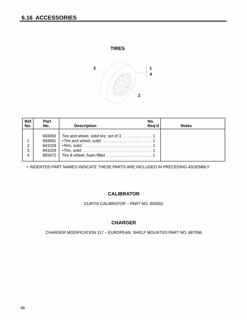
6.16 ACCESSORIES
46
14
3
2
TIRES
Ref.No.
PartNo. Description Notes
No.Req’d
• INDENTED PART NAMES INDICATE THESE PARTS ARE INCLUDED IN PRECEDING ASSEMBLY
893092 Tire and wheel, solid tire, set of 3 1. . . . . . . . . . . . . . 1 893091 •Tire and wheel, solid 1. . . . . . . . . . . . . . . . . . . . . . . . 2 841028 •Rim, solid 1. . . . . . . . . . . . . . . . . . . . . . . . . . . . . . . . . . 3 841029 •Tire, solid 1. . . . . . . . . . . . . . . . . . . . . . . . . . . . . . . . . . 4 893472 Tire & wheel, foam filled 1. . . . . . . . . . . . . . . . . . . . . .
CALIBRATOR
CURTIS CALIBRATOR – PART NO. 893052
CHARGER
CHARGER MODIFICATION 117 – EUROPEAN, SHELF MOUNTED PART NO. 887096

47
WIRINGDIAGRAMS

7 WIRING DIAGRAM
48
20 AMPCIRCUIT
BREAKER
HOURMETER
TAILLIGHT
RELAY POTASSEMBLY
CHARGER
REVERSEWARNINGBUZZER
SEAT SWITCH
STOPLIGHTSWITCH
SWITCH(ACC. PEDAL)
BRIDGERECTIFIER
NOTES:P2– REVERSEP3– FORWARDP5– POT HIGHP6– 0–5V INPUTP7– POT LOWP11– REVERSE (INPUT)P12– FORWARD (INPUT)P14– HIGH SPEED (INPUT)P16– KEYSWITCH (INPUT)
REARLIGHT
REAR LIGHT(GND)
A–YELLOWB–WHITEC–BLUE
TL (+12V) BL (+12V)
CONTROLLERP7
P6P5
P14P11
P12P16
P2P3
M–B–
B+A2
892833891862
890495
891655
887855
892999891753
MOTOR
REVERSINGCONTROL
CONTROLLER
A MODELS
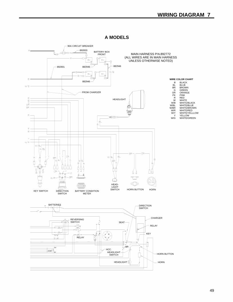
WIRING DIAGRAM 7
49
CHARGER
RELAY
90A CIRCUIT BREAKER
892901
892833BATTERY BOX
FRONT
FROM CHARGER
MAIN HARNESS P.N.892772(ALL WIRES ARE IN MAIN HARNESS
UNLESS OTHERWISE NOTED)
HEADLIGHT
HORNHORN BUTTON
HEAD-LIGHT
SWITCHBATTERY CONDITION
METERDIRECTION
SWITCHKEY SWITCH
BATTERIES
REVERSINGSWITCH
RELAY
ACC.OV
5VCCW
HEADLIGHTSWITCH
KEY
SEAT
DIRECTIONSWITCH
HORN BUTTON
BR
B BLACKBL BLUEBR BROWN
G GREENOR ORANGEPK PINK
R REDW WHITE
W/B WHITE/BLACKW/BL WHITE/BLUEW/BR WHITE/BROWN
W/R WHITE/REDW/Y WHITE/YELLLOW
Y YELLOWW/G WHITE/GREEN
WIRE COLOR CHART
HORNHEADLIGHT
882946
882946
882946
A MODELS
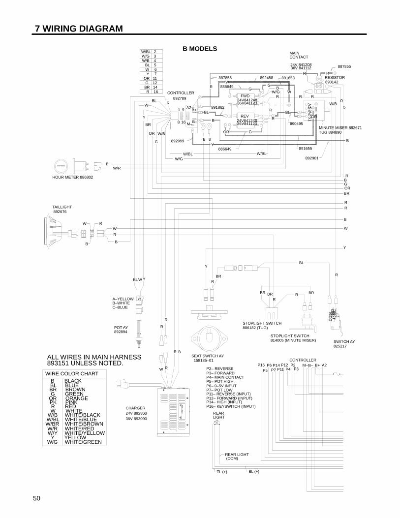
8
P14CONTROLLERP2P12
16 M–
892999
891653
890495
891862
REAR LIGHT (COM)
886649
886649
887855 892458
TL (+) BL (+)
C
B
W R
891655
RESISTOR893142
P4
REVBL
OR
OR
W
B
BRBR R
Y
W/B 4
CHARGER24V 89286036V 893090
R
STOPLIGHT SWITCH814005 (MINUTE MISER)
STOPLIGHT SWITCH886182 (TUG)
MINUTE MISER 892671TUG 884890
HOUR METER 886802
SWITCH AY825217
BL
R
R
W/R
R
R
W/B
B
B
R
R
W/BL
R
W/G
R
G
BL
G
BR
R
RW
Y
A–YELLOWB–WHITEC–BLUE
OR
Y
WBL
OR 11Y 7
W 6BL 5
TAILLIGHT 892676
CONTROLLER892789
A2B+B–M–P3
P16P11P5
P6P7
REARLIGHT
P2– REVERSEP3– FORWARDP4– MAIN CONTACTP5– POT HIGHP6– 0–5V INPUTP7– POT LOWP11– REVERSE (INPUT)P12– FORWARD (INPUT)P14– HIGH (INPUT)P16– KEYSWITCH (INPUT)
FWD
24V 84120836V 841112
R
RPOT AY892894
W
CA
UT
ION
1 9
W/BL 2W/G 3
G 12BR 14
R 16
W/B
R
W
BL
G
BR
R
W/BLW/G
B
R
A2
B–
B+
BR
Y
B
W
R
ALL WIRES IN MAIN HARNESS893151 UNLESS NOTED.
SEAT SWITCH AY 158135–01
WIRE COLOR CHART B BLACK BL BLUE BR BROWN G GREEN
OR ORANGE PK PINK R RED W WHITE
W/B WHITE/BLACK W/BL WHITE/BLUE W/BR WHITE/BROWN W/R WHITE/RED W/Y WHITE/YELLOW
Y YELLOW W/G WHITE/GREEN
R
B
G
BR
A1
S1
A2
S2
1 23N
CN
OC
OM
B MODELS
MAINCONTACT
24V84124836V841123
24V84124836V841123
B
RBGORBR
RR
B
W
Y
887855
892901
7 WIRING DIAGRAM
50

CIRCUIT BRKR: MINUTE MISER 829164 TUG 824800
BR
S1
BRR
OR G
OPTIONALQUICK
DISCONNECT
AC RELAY
883078
CHARGER
HORN BUTTON
KEY
SEAT SW
YY
Y
HORN 886090
OR
EC TUG MM
TUG LIFTOUT RACK
BROR
OR
CONNECTION FOR WIRINGHORN WITH TUG STEERING WHEEL MOD.
OR
FO
RW
AR
D
RE
VE
RS
E
891693
891657
EC TUG MM
884045
887204
TUG LIFTOUT RACK
893383 893282
TOCIRCUITBRKR
24V MINUTE MISER
FRONT
6V
6V 6V
6V
B
36V TUG
B
FOOT SWITCH
W/B
BRIDGERECTIFIER 840679
B
RB
W/BW/B
BR
R
R
BR
B B
BBL
6V
MINUTE MISERBRAKE LIGHT SW
6V
MAIN CONTACT
0R
2 4 1
CCW
0V
5V
DIRECTIONSWITCH
TUG BRAKE LIGHT SW
HEADLIGHTSWITCH
A2S2
A1
+
ACAC
B– B+
FORWARD
REVERSE
REVERSEWARNINGBUZZER890000
BATTERIES
Y W/BL
W/BL
W/BL
W/B
W/B
Y G
YBR
BR
W
B
B
W/BL
Y
YR
B R
20 AMPCIRCUIT BREAKER
829780
BR
KEY SWITCH 886311
892523HEADLIGHT
AC
CIG
N
BA
TT
B
BL
6V
6V
HEADLIGHT SWITCH
830640 HORN BUTTON
806791
FRONT
R
6V
6V
B MODELS
DIRECTIONSWITCH836354
BATTERYCONDITIONMETER:24V 84052636V 841111
HEADLIGHT
HORN
BCI
HOURMETER
REVALARM
RR
B
W
Y
0RBR
GBR
892833
WIRING DIAGRAM 7
51

8
P14CONTROLLERP2P12
16 M–
892999
891653
890495
891862
REAR LIGHT (COM)
886649
886649
887855 892458
TL (+) BL (+)
C
B
W R
891655
RESISTOR893142
P4
REVBL
OR
OR
W
B
BRBR R
Y
W/B 4
CHARGER24V 89286036V 893090
STOPLIGHT SWITCH814005 (MINUTE MISER)
STOPLIGHT SWITCH886182 (TUG)
MINUTE MISER 892671TUG 884890
HOUR METER 886802
BL
R
R
W/R
R
W/B
B
B
R
R
W/BL
R
W/G
G
BL
G
BR
R
RW
Y
A–YELLOWB–WHITEC–BLUE
OR
Y
WBL
OR 11Y 7
W 6BL 5
TAILLIGHT 892676
CONTROLLER892789
A2B+B–M–P3
P16P11P5
P6P7
REARLIGHT
P2– REVERSEP3– FORWARDP4– MAIN CONTACTP5– POT HIGHP6– 0–5V INPUTP7– POT LOWP11– REVERSE (INPUT)P12– FORWARD (INPUT)P14– HIGH (INPUT)P16– KEYSWITCH (INPUT)
FWD
24V 84120836V 841112
R
RPOT AY892894
W
CA
UT
ION
1 9
W/BL 2W/G 3
G 12BR 14
W/B
R
W
G
BR
R
W/BLW/G
B
R
A2
B–
B+
BR
Y
B
W
R
ALL WIRES IN MAIN HARNESS SEAT SWITCH AY 158135–01
WIRE COLOR CHART B BLACK BL BLUE BR BROWN G GREEN
OR ORANGE PK PINK R RED W WHITE
W/B WHITE/BLACK W/BL WHITE/BLUE W/BR WHITE/BROWN W/R WHITE/RED W/Y WHITE/YELLOW
Y YELLOW W/G WHITE/GREEN
R
B
G
A1
S1
A2
S2
B MODELSWITH SERIAL NO. 9601-2494 OR LATER
AND MODEL 898323 MAINCONTACT
24V84124836V841123
24V84124836V841123
B
RBGORBR
RR
B
W
Y
887855
W/R
R
R
DIODE884398
897160 UNLESS NOTED.
W/Y
W/Y
892901
Y
Y
84076616–CONNECTOR
840765TERMINAL
W/Y 16R 15
7 WIRING DIAGRAM
52

MEMORYMODULE841852
BR
S1
BRR
OR G
OPTIONALQUICK
DISCONNECT
AC RELAY
883078
CHARGER
HORN BUTTON
KEY
SEAT SW
YY
Y
HORN 886090
OR
EC TUG MM
TUG LIFTOUT RACK
BROR
OR
CONNECTION FOR WIRINGHORN WITH TUG STEERING WHEEL MOD.
OR
FO
RW
AR
D
RE
VE
RS
E891693
891657
EC TUG MM
884045
887204
TUG LIFTOUT RACK
893383893282
TOCIRCUITBRKR
24V MINUTE MISER
FRONT
6V
6V 6V
6V
B
36V TUG
B
FOOT SWITCH
W/B
BRIDGERECTIFIER 840679
B
RB
W/BW/B
BR
CIRCUIT BRKR: MINUTE MISER 829164 TUG 824800
R
R
BR
B B
BBL
6V
MINUTE MISERBRAKE LIGHT SW
6V
MAIN CONTACT
0R
2 4 1
CCW
0V
5V
DIRECTIONSWITCH
TUG BRAKE LIGHT SW
HEADLIGHTSWITCH
A2S2
A1
+
ACAC
B– B+
FORWARD
REVERSE
REVERSEWARNINGBUZZER890000
BATTERIES
Y W/BL
W/BL
W/BL
W/B
W/B
Y G
YBR
BR
W
B
B
W/BL
Y
YR
B R
20 AMPCIRCUIT BREAKER
829780
BR
KEY SWITCH 886311
892523HEADLIGHT
AC
CIG
N
BA
TT
B
BL
6V
6V
HEADLIGHT SWITCH
830640 HORN BUTTON
806791
FRONT
R
6V
6V
B MODELSWITH SERIAL NO. 9601-2494 OR LATER
AND MODEL 898323
DIRECTIONSWITCH836354
BATTERYCONDITIONMETER:24V 84052636V 841111
HEADLIGHT
HORN
BCI
HOURMETER
REVALARM
RR
B
W
Y
0RBR
GBR
B
2 4 1
W/BLB RB
3
RB
NOT USED ON STD.BAT. COND. METER
WIRE DESTINATIONSSAME AS STD. METER
36V BAT. COND.METER 841851
LIFTOUT BATTERY RACK APPLICATION(24V MINUTE MISER
BATTERY ARRANGEMENTSHOWN IN SCHEMATIC)
892833
Y
Y
WIRING DIAGRAM 7
53
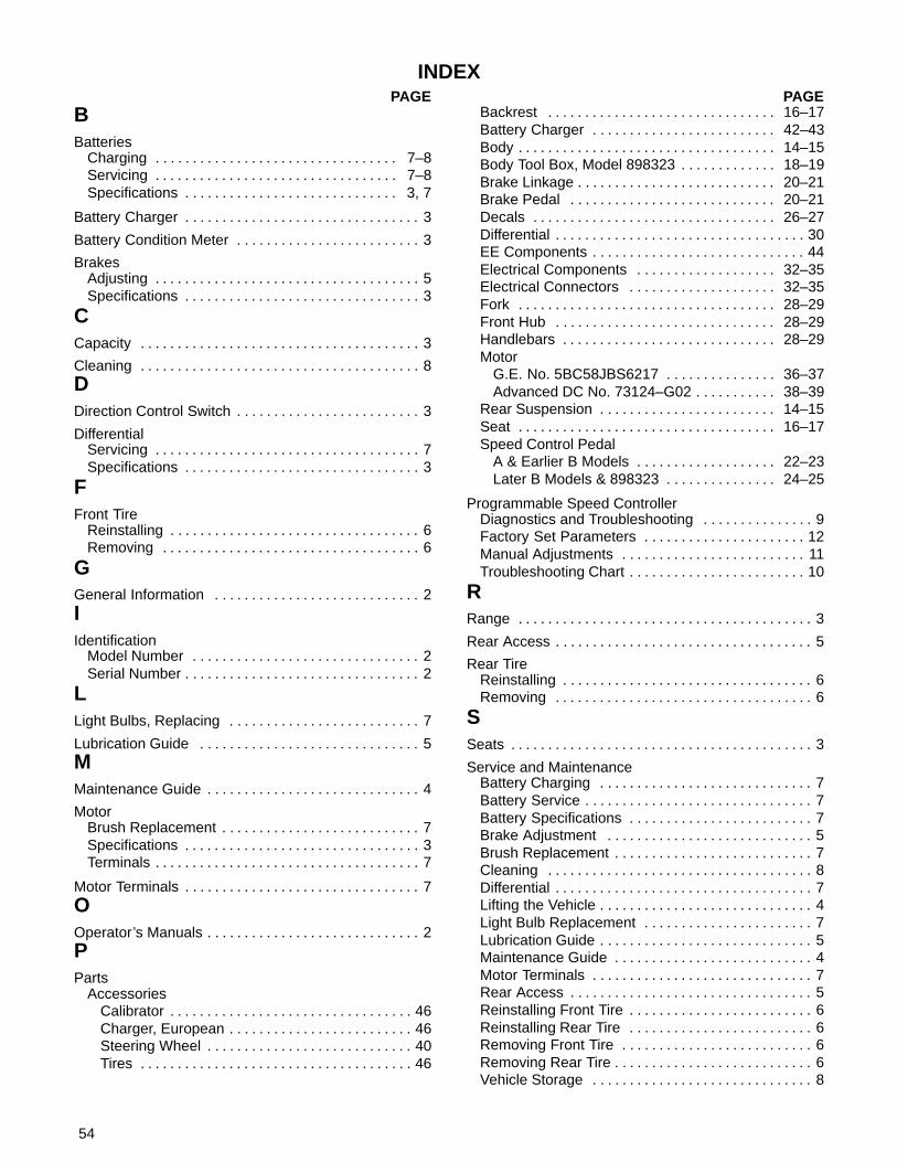
54
INDEXPAGE
BBatteries
Charging 7–8. . . . . . . . . . . . . . . . . . . . . . . . . . . . . . . . . Servicing 7–8. . . . . . . . . . . . . . . . . . . . . . . . . . . . . . . . . Specifications 3, 7. . . . . . . . . . . . . . . . . . . . . . . . . . . . .
Battery Charger 3. . . . . . . . . . . . . . . . . . . . . . . . . . . . . . . .
Battery Condition Meter 3. . . . . . . . . . . . . . . . . . . . . . . . .
BrakesAdjusting 5. . . . . . . . . . . . . . . . . . . . . . . . . . . . . . . . . . . . Specifications 3. . . . . . . . . . . . . . . . . . . . . . . . . . . . . . . .
CCapacity 3. . . . . . . . . . . . . . . . . . . . . . . . . . . . . . . . . . . . . .
Cleaning 8. . . . . . . . . . . . . . . . . . . . . . . . . . . . . . . . . . . . . . DDirection Control Switch 3. . . . . . . . . . . . . . . . . . . . . . . . .
DifferentialServicing 7. . . . . . . . . . . . . . . . . . . . . . . . . . . . . . . . . . . . Specifications 3. . . . . . . . . . . . . . . . . . . . . . . . . . . . . . . .
FFront Tire
Reinstalling 6. . . . . . . . . . . . . . . . . . . . . . . . . . . . . . . . . . Removing 6. . . . . . . . . . . . . . . . . . . . . . . . . . . . . . . . . . .
GGeneral Information 2. . . . . . . . . . . . . . . . . . . . . . . . . . . . IIdentification
Model Number 2. . . . . . . . . . . . . . . . . . . . . . . . . . . . . . . Serial Number 2. . . . . . . . . . . . . . . . . . . . . . . . . . . . . . . .
LLight Bulbs, Replacing 7. . . . . . . . . . . . . . . . . . . . . . . . . .
Lubrication Guide 5. . . . . . . . . . . . . . . . . . . . . . . . . . . . . . MMaintenance Guide 4. . . . . . . . . . . . . . . . . . . . . . . . . . . . .
MotorBrush Replacement 7. . . . . . . . . . . . . . . . . . . . . . . . . . . Specifications 3. . . . . . . . . . . . . . . . . . . . . . . . . . . . . . . . Terminals 7. . . . . . . . . . . . . . . . . . . . . . . . . . . . . . . . . . . .
Motor Terminals 7. . . . . . . . . . . . . . . . . . . . . . . . . . . . . . . . OOperator’s Manuals 2. . . . . . . . . . . . . . . . . . . . . . . . . . . . . PParts
AccessoriesCalibrator 46. . . . . . . . . . . . . . . . . . . . . . . . . . . . . . . . . Charger, European 46. . . . . . . . . . . . . . . . . . . . . . . . . Steering Wheel 40. . . . . . . . . . . . . . . . . . . . . . . . . . . . Tires 46. . . . . . . . . . . . . . . . . . . . . . . . . . . . . . . . . . . . .
PAGEBackrest 16–17. . . . . . . . . . . . . . . . . . . . . . . . . . . . . . . Battery Charger 42–43. . . . . . . . . . . . . . . . . . . . . . . . . Body 14–15. . . . . . . . . . . . . . . . . . . . . . . . . . . . . . . . . . . Body Tool Box, Model 898323 18–19. . . . . . . . . . . . . Brake Linkage 20–21. . . . . . . . . . . . . . . . . . . . . . . . . . . Brake Pedal 20–21. . . . . . . . . . . . . . . . . . . . . . . . . . . . Decals 26–27. . . . . . . . . . . . . . . . . . . . . . . . . . . . . . . . . Differential 30. . . . . . . . . . . . . . . . . . . . . . . . . . . . . . . . . . EE Components 44. . . . . . . . . . . . . . . . . . . . . . . . . . . . . Electrical Components 32–35. . . . . . . . . . . . . . . . . . . Electrical Connectors 32–35. . . . . . . . . . . . . . . . . . . . Fork 28–29. . . . . . . . . . . . . . . . . . . . . . . . . . . . . . . . . . . Front Hub 28–29. . . . . . . . . . . . . . . . . . . . . . . . . . . . . . Handlebars 28–29. . . . . . . . . . . . . . . . . . . . . . . . . . . . . Motor
G.E. No. 5BC58JBS6217 36–37. . . . . . . . . . . . . . . Advanced DC No. 73124–G02 38–39. . . . . . . . . . .
Rear Suspension 14–15. . . . . . . . . . . . . . . . . . . . . . . . Seat 16–17. . . . . . . . . . . . . . . . . . . . . . . . . . . . . . . . . . . Speed Control Pedal
A & Earlier B Models 22–23. . . . . . . . . . . . . . . . . . . Later B Models & 898323 24–25. . . . . . . . . . . . . . .
Programmable Speed ControllerDiagnostics and Troubleshooting 9. . . . . . . . . . . . . . . Factory Set Parameters 12. . . . . . . . . . . . . . . . . . . . . . Manual Adjustments 11. . . . . . . . . . . . . . . . . . . . . . . . . Troubleshooting Chart 10. . . . . . . . . . . . . . . . . . . . . . . .
RRange 3. . . . . . . . . . . . . . . . . . . . . . . . . . . . . . . . . . . . . . . .
Rear Access 5. . . . . . . . . . . . . . . . . . . . . . . . . . . . . . . . . . .
Rear TireReinstalling 6. . . . . . . . . . . . . . . . . . . . . . . . . . . . . . . . . . Removing 6. . . . . . . . . . . . . . . . . . . . . . . . . . . . . . . . . . .
SSeats 3. . . . . . . . . . . . . . . . . . . . . . . . . . . . . . . . . . . . . . . . .
Service and MaintenanceBattery Charging 7. . . . . . . . . . . . . . . . . . . . . . . . . . . . . Battery Service 7. . . . . . . . . . . . . . . . . . . . . . . . . . . . . . . Battery Specifications 7. . . . . . . . . . . . . . . . . . . . . . . . . Brake Adjustment 5. . . . . . . . . . . . . . . . . . . . . . . . . . . . Brush Replacement 7. . . . . . . . . . . . . . . . . . . . . . . . . . . Cleaning 8. . . . . . . . . . . . . . . . . . . . . . . . . . . . . . . . . . . . Differential 7. . . . . . . . . . . . . . . . . . . . . . . . . . . . . . . . . . . Lifting the Vehicle 4. . . . . . . . . . . . . . . . . . . . . . . . . . . . . Light Bulb Replacement 7. . . . . . . . . . . . . . . . . . . . . . . Lubrication Guide 5. . . . . . . . . . . . . . . . . . . . . . . . . . . . . Maintenance Guide 4. . . . . . . . . . . . . . . . . . . . . . . . . . . Motor Terminals 7. . . . . . . . . . . . . . . . . . . . . . . . . . . . . . Rear Access 5. . . . . . . . . . . . . . . . . . . . . . . . . . . . . . . . . Reinstalling Front Tire 6. . . . . . . . . . . . . . . . . . . . . . . . . Reinstalling Rear Tire 6. . . . . . . . . . . . . . . . . . . . . . . . . Removing Front Tire 6. . . . . . . . . . . . . . . . . . . . . . . . . . Removing Rear Tire 6. . . . . . . . . . . . . . . . . . . . . . . . . . . Vehicle Storage 8. . . . . . . . . . . . . . . . . . . . . . . . . . . . . .

55
INDEXPAGE
Service Manual 2. . . . . . . . . . . . . . . . . . . . . . . . . . . . . . . .
Special Tools 3. . . . . . . . . . . . . . . . . . . . . . . . . . . . . . . . . .
Specifications 3. . . . . . . . . . . . . . . . . . . . . . . . . . . . . . . . . . Batteries 3. . . . . . . . . . . . . . . . . . . . . . . . . . . . . . . . . . . . Battery Condition Meter 3. . . . . . . . . . . . . . . . . . . . . . . Brakes 3. . . . . . . . . . . . . . . . . . . . . . . . . . . . . . . . . . . . . . Capacity 3. . . . . . . . . . . . . . . . . . . . . . . . . . . . . . . . . . . . Charger 3. . . . . . . . . . . . . . . . . . . . . . . . . . . . . . . . . . . . . Differential 3. . . . . . . . . . . . . . . . . . . . . . . . . . . . . . . . . . . Dimensions 3. . . . . . . . . . . . . . . . . . . . . . . . . . . . . . . . . . Direction Control Switch 3. . . . . . . . . . . . . . . . . . . . . . . Motor 3. . . . . . . . . . . . . . . . . . . . . . . . . . . . . . . . . . . . . . . Optional batteries 3. . . . . . . . . . . . . . . . . . . . . . . . . . . . . Range 3. . . . . . . . . . . . . . . . . . . . . . . . . . . . . . . . . . . . . . Seats 3. . . . . . . . . . . . . . . . . . . . . . . . . . . . . . . . . . . . . . . Speed Control 3. . . . . . . . . . . . . . . . . . . . . . . . . . . . . . . . Steering 3. . . . . . . . . . . . . . . . . . . . . . . . . . . . . . . . . . . . . Suspension 3. . . . . . . . . . . . . . . . . . . . . . . . . . . . . . . . . . Tire Pressure 3. . . . . . . . . . . . . . . . . . . . . . . . . . . . . . . . Tire Size 3. . . . . . . . . . . . . . . . . . . . . . . . . . . . . . . . . . . .
Speed Control 3. . . . . . . . . . . . . . . . . . . . . . . . . . . . . . . . .
Speed ControllerDiagnostics and Troubleshooting 9. . . . . . . . . . . . . . . Factory Set Parameters 12. . . . . . . . . . . . . . . . . . . . . . Manual Adjustments 11. . . . . . . . . . . . . . . . . . . . . . . . . Troubleshooting Chart 9–10. . . . . . . . . . . . . . . . . . . . .
Steering, Specifications 3. . . . . . . . . . . . . . . . . . . . . . . . .
Storage 8. . . . . . . . . . . . . . . . . . . . . . . . . . . . . . . . . . . . . . .
PAGE
SuspensionFront 3. . . . . . . . . . . . . . . . . . . . . . . . . . . . . . . . . . . . . . . . Rear 3. . . . . . . . . . . . . . . . . . . . . . . . . . . . . . . . . . . . . . . .
TTire Condition 6. . . . . . . . . . . . . . . . . . . . . . . . . . . . . . . . . .
Tire Pressure 6. . . . . . . . . . . . . . . . . . . . . . . . . . . . . . . . . .
TiresCondition 6. . . . . . . . . . . . . . . . . . . . . . . . . . . . . . . . . . . . Pressure 3, 6. . . . . . . . . . . . . . . . . . . . . . . . . . . . . . . . . Reinstalling Front 6. . . . . . . . . . . . . . . . . . . . . . . . . . . . . Reinstalling Rear 6. . . . . . . . . . . . . . . . . . . . . . . . . . . . . Removing Front 6. . . . . . . . . . . . . . . . . . . . . . . . . . . . . . Removing Rear 6. . . . . . . . . . . . . . . . . . . . . . . . . . . . . . Size 3. . . . . . . . . . . . . . . . . . . . . . . . . . . . . . . . . . . . . . . .
Torque Chart 13. . . . . . . . . . . . . . . . . . . . . . . . . . . . . . . . . .
Touch–up Paint 8. . . . . . . . . . . . . . . . . . . . . . . . . . . . . . . . VVehicle
Cleaning 8. . . . . . . . . . . . . . . . . . . . . . . . . . . . . . . . . . . . Dimensions 3. . . . . . . . . . . . . . . . . . . . . . . . . . . . . . . . . . Lifting 4. . . . . . . . . . . . . . . . . . . . . . . . . . . . . . . . . . . . . . . Lubrication 5. . . . . . . . . . . . . . . . . . . . . . . . . . . . . . . . . . . Range 3. . . . . . . . . . . . . . . . . . . . . . . . . . . . . . . . . . . . . . Storage 8. . . . . . . . . . . . . . . . . . . . . . . . . . . . . . . . . . . . .
WWheel Bearings, Servicing 7. . . . . . . . . . . . . . . . . . . . . . .
Wiring DiagramA Models 48–49. . . . . . . . . . . . . . . . . . . . . . . . . . . . . . . B Models 50–51. . . . . . . . . . . . . . . . . . . . . . . . . . . . . . . Later B Models & Model 898323 52–53. . . . . . . . . . .

56
PART NUMBER INDEXPart PageNo. No.158135–01 17. . . . . . . . . . . . . . . 2700812 31. . . . . . . . . . . . . . . . . 2701213 45. . . . . . . . . . . . . . . . . 2701550 35. . . . . . . . . . . . . . . . . 2702875.7 45. . . . . . . . . . . . . . . . 2702915 45. . . . . . . . . . . . . . . . . 2702994 45. . . . . . . . . . . . . . . . . 2703038.7 45. . . . . . . . . . . . . . . . 2703039.7 45. . . . . . . . . . . . . . . . 2703735 33. . . . . . . . . . . . . . . . . 2703900.7 21. . . . . . . . . . . . . . . . 2703903.7 21. . . . . . . . . . . . . . . . 306367 41. . . . . . . . . . . . . . . . . . 310546 41. . . . . . . . . . . . . . . . . . 38061A 17, 19. . . . . . . . . . . . . . 38541 17, 19. . . . . . . . . . . . . . . . 517163 21. . . . . . . . . . . . . . . . . . 548225 41. . . . . . . . . . . . . . . . . . 548478 23, 25. . . . . . . . . . . . . . 700290 29. . . . . . . . . . . . . . . . . . 73120–G03 39. . . . . . . . . . . . . . . 73120–G05 39. . . . . . . . . . . . . . . 73120–G06 39. . . . . . . . . . . . . . . 73120–G07 39. . . . . . . . . . . . . . . 73120–G08 39. . . . . . . . . . . . . . . 73120–G09 39. . . . . . . . . . . . . . . 73120–G10 39. . . . . . . . . . . . . . . 73120–G11 39. . . . . . . . . . . . . . . 73120–G15 39. . . . . . . . . . . . . . . 73124–G02 39. . . . . . . . . . . . . . . 805421, 23 25. . . . . . . . . . . . . . . 805437 15. . . . . . . . . . . . . . . . . . 806703 21. . . . . . . . . . . . . . . . . . 806714 21. . . . . . . . . . . . . . . . . . 806791 29. . . . . . . . . . . . . . . . . . 807290 29. . . . . . . . . . . . . . . . . . 807332 15. . . . . . . . . . . . . . . . . . 807472 29. . . . . . . . . . . . . . . . . . 808935 41. . . . . . . . . . . . . . . . . . 810722 21. . . . . . . . . . . . . . . . . . 814005 21. . . . . . . . . . . . . . . . . . 814473 29. . . . . . . . . . . . . . . . . . 814474 29. . . . . . . . . . . . . . . . . . 814924 33. . . . . . . . . . . . . . . . . . 816447 41. . . . . . . . . . . . . . . . . . 816455 41. . . . . . . . . . . . . . . . . . 816456 41. . . . . . . . . . . . . . . . . . 816667 15. . . . . . . . . . . . . . . . . . 817507 21. . . . . . . . . . . . . . . . . . 817719 33. . . . . . . . . . . . . . . . . . 818303 15. . . . . . . . . . . . . . . . . . 819936 19, 27. . . . . . . . . . . . . . 822048 43. . . . . . . . . . . . . . . . . . 822313 21. . . . . . . . . . . . . . . . . . 823549 17, 19. . . . . . . . . . . . . . 823621 15. . . . . . . . . . . . . . . . . . 823749 43. . . . . . . . . . . . . . . . . .
825328 27. . . . . . . . . . . . . . . . . . 825366 15. . . . . . . . . . . . . . . . . . 825387 19, 27. . . . . . . . . . . . . . 825748 35. . . . . . . . . . . . . . . . . . 825880 33. . . . . . . . . . . . . . . . . . 825884 33. . . . . . . . . . . . . . . . . . 825886 35. . . . . . . . . . . . . . . . . . 825919 41. . . . . . . . . . . . . . . . . . 826005 33. . . . . . . . . . . . . . . . . . 826006 33. . . . . . . . . . . . . . . . . . 826726 33. . . . . . . . . . . . . . . . . . 826747 17. . . . . . . . . . . . . . . . . . 827188 41. . . . . . . . . . . . . . . . . . 828247 15. . . . . . . . . . . . . . . . . . 829164 33. . . . . . . . . . . . . . . . . . 829694 35. . . . . . . . . . . . . . . . . . 829754 23. . . . . . . . . . . . . . . . . . 829780 33. . . . . . . . . . . . . . . . . . 829860 21. . . . . . . . . . . . . . . . . . 830168 41. . . . . . . . . . . . . . . . . . 830640 33. . . . . . . . . . . . . . . . . . 830661 21. . . . . . . . . . . . . . . . . . 830784 21. . . . . . . . . . . . . . . . . . 831443 19, 27. . . . . . . . . . . . . . 831909 29. . . . . . . . . . . . . . . . . . 832555 41. . . . . . . . . . . . . . . . . . 833104 23, 25. . . . . . . . . . . . . . 835481 33. . . . . . . . . . . . . . . . . . 836354 33. . . . . . . . . . . . . . . . . . 837855 41. . . . . . . . . . . . . . . . . . 839849 35. . . . . . . . . . . . . . . . . . 839850 35. . . . . . . . . . . . . . . . . . 839917 33. . . . . . . . . . . . . . . . . . 839918 35. . . . . . . . . . . . . . . . . . 839921 35. . . . . . . . . . . . . . . . . . 839935 35. . . . . . . . . . . . . . . . . . 840017 41. . . . . . . . . . . . . . . . . . 840117 35. . . . . . . . . . . . . . . . . . . 840118 35. . . . . . . . . . . . . . . . . . . 840177 45. . . . . . . . . . . . . . . . . . 840273 35. . . . . . . . . . . . . . . . . . 840318 29. . . . . . . . . . . . . . . . . . 840324 29. . . . . . . . . . . . . . . . . . 840325 29. . . . . . . . . . . . . . . . . . 840326 21. . . . . . . . . . . . . . . . . . 840335 21. . . . . . . . . . . . . . . . . . 840372 29. . . . . . . . . . . . . . . . . . 840419 23, 25. . . . . . . . . . . . . . 840435 23, 25. . . . . . . . . . . . . . 840458 29. . . . . . . . . . . . . . . . . . 840479 29. . . . . . . . . . . . . . . . . . 840491 21, 35. . . . . . . . . . . . . . 840494 21, 23, 25. . . . . . . . . . . 840496 35. . . . . . . . . . . . . . . . . . 840499 17. . . . . . . . . . . . . . . . . . 840508 17, 19. . . . . . . . . . . . . . 840526 35. . . . . . . . . . . . . . . . . . 840528 15, 19. . . . . . . . . . . . . . 840666 21. . . . . . . . . . . . . . . . . .
840667 21. . . . . . . . . . . . . . . . . . 840676 35. . . . . . . . . . . . . . . . . . 840679 35. . . . . . . . . . . . . . . . . . 840684 15, 19. . . . . . . . . . . . . . 840687 23. . . . . . . . . . . . . . . . . . 840688 23, 25. . . . . . . . . . . . . . 840689 29. . . . . . . . . . . . . . . . . . 840691 19, 27. . . . . . . . . . . . . . 840695 15. . . . . . . . . . . . . . . . . . 840696 19, 27. . . . . . . . . . . . . . 840770 15, 19. . . . . . . . . . . . . . 840807 31. . . . . . . . . . . . . . . . . . 840808 31. . . . . . . . . . . . . . . . . . 840809 31. . . . . . . . . . . . . . . . . . 840810 31. . . . . . . . . . . . . . . . . . 840814 31. . . . . . . . . . . . . . . . . . 840815 31. . . . . . . . . . . . . . . . . . 840816 31. . . . . . . . . . . . . . . . . . 840817 31. . . . . . . . . . . . . . . . . . 840818 31. . . . . . . . . . . . . . . . . . 840819 31. . . . . . . . . . . . . . . . . . 840821 31. . . . . . . . . . . . . . . . . . 840822 31. . . . . . . . . . . . . . . . . . 840823 31. . . . . . . . . . . . . . . . . . 840843 29, 31. . . . . . . . . . . . . . 840844 31. . . . . . . . . . . . . . . . . . 840854 35. . . . . . . . . . . . . . . . . . 840860 35. . . . . . . . . . . . . . . . . . 840871 19, 27. . . . . . . . . . . . . . 840981 41. . . . . . . . . . . . . . . . . . 840982 41. . . . . . . . . . . . . . . . . . 840983 41. . . . . . . . . . . . . . . . . . 841028 46. . . . . . . . . . . . . . . . . . 841029 46. . . . . . . . . . . . . . . . . . 841208 35. . . . . . . . . . . . . . . . . . 841248 35. . . . . . . . . . . . . . . . . . 841860 27. . . . . . . . . . . . . . . . . . 842261 19. . . . . . . . . . . . . . . . . . 842265 19. . . . . . . . . . . . . . . . . . 842271 19. . . . . . . . . . . . . . . . . . 844328 45. . . . . . . . . . . . . . . . . . 844847 27. . . . . . . . . . . . . . . . . . 845050 35. . . . . . . . . . . . . . . . . . 845183 31. . . . . . . . . . . . . . . . . . 845184 31. . . . . . . . . . . . . . . . . . 845315 31. . . . . . . . . . . . . . . . . . 845316 31. . . . . . . . . . . . . . . . . . 869184 25. . . . . . . . . . . . . . . . . . 876660 15. . . . . . . . . . . . . . . . . . 880631 35. . . . . . . . . . . . . . . . . . 883216 43. . . . . . . . . . . . . . . . . . 883844 43. . . . . . . . . . . . . . . . . . 883938 17, 19. . . . . . . . . . . . . . 884302 19. . . . . . . . . . . . . . . . . . 884683 17. . . . . . . . . . . . . . . . . . 886090 35. . . . . . . . . . . . . . . . . . 886311 35. . . . . . . . . . . . . . . . . . . 886435 43. . . . . . . . . . . . . . . . . . 886735 29, 31. . . . . . . . . . . . . .
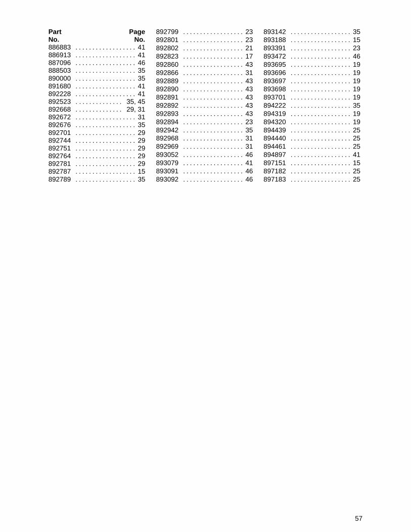
57
Part PageNo. No.886883 41. . . . . . . . . . . . . . . . . . 886913 41. . . . . . . . . . . . . . . . . . 887096 46. . . . . . . . . . . . . . . . . . 888503 35. . . . . . . . . . . . . . . . . . 890000 35. . . . . . . . . . . . . . . . . . 891680 41. . . . . . . . . . . . . . . . . . 892228 41. . . . . . . . . . . . . . . . . . 892523 35, 45. . . . . . . . . . . . . . 892668 29, 31. . . . . . . . . . . . . . 892672 31. . . . . . . . . . . . . . . . . . 892676 35. . . . . . . . . . . . . . . . . . 892701 29. . . . . . . . . . . . . . . . . . 892744 29. . . . . . . . . . . . . . . . . . 892751 29. . . . . . . . . . . . . . . . . . 892764 29. . . . . . . . . . . . . . . . . . 892781 29. . . . . . . . . . . . . . . . . . 892787 15. . . . . . . . . . . . . . . . . . 892789 35. . . . . . . . . . . . . . . . . .
892799 23. . . . . . . . . . . . . . . . . . 892801 23. . . . . . . . . . . . . . . . . . 892802 21. . . . . . . . . . . . . . . . . . 892823 17. . . . . . . . . . . . . . . . . . 892860 43. . . . . . . . . . . . . . . . . . 892866 31. . . . . . . . . . . . . . . . . . 892889 43. . . . . . . . . . . . . . . . . . 892890 43. . . . . . . . . . . . . . . . . . 892891 43. . . . . . . . . . . . . . . . . . 892892 43. . . . . . . . . . . . . . . . . . 892893 43. . . . . . . . . . . . . . . . . . 892894 23. . . . . . . . . . . . . . . . . . 892942 35. . . . . . . . . . . . . . . . . . 892968 31. . . . . . . . . . . . . . . . . . 892969 31. . . . . . . . . . . . . . . . . . 893052 46. . . . . . . . . . . . . . . . . . 893079 41. . . . . . . . . . . . . . . . . . 893091 46. . . . . . . . . . . . . . . . . . 893092 46. . . . . . . . . . . . . . . . . .
893142 35. . . . . . . . . . . . . . . . . . 893188 15. . . . . . . . . . . . . . . . . . 893391 23. . . . . . . . . . . . . . . . . . 893472 46. . . . . . . . . . . . . . . . . . 893695 19. . . . . . . . . . . . . . . . . . 893696 19. . . . . . . . . . . . . . . . . . 893697 19. . . . . . . . . . . . . . . . . . 893698 19. . . . . . . . . . . . . . . . . . 893701 19. . . . . . . . . . . . . . . . . . 894222 35. . . . . . . . . . . . . . . . . . 894319 19. . . . . . . . . . . . . . . . . . 894320 19. . . . . . . . . . . . . . . . . . 894439 25. . . . . . . . . . . . . . . . . . 894440 25. . . . . . . . . . . . . . . . . . 894461 25. . . . . . . . . . . . . . . . . . 894897 41. . . . . . . . . . . . . . . . . . 897151 15. . . . . . . . . . . . . . . . . . 897182 25. . . . . . . . . . . . . . . . . . 897183 25. . . . . . . . . . . . . . . . . .