Particle systems, collision detection, and ray tracing · – Explosions – Galaxies 3 Based on...
42
Particle systems, collision detection, and ray tracing Computer Graphics CSE 167 Lecture 17
Transcript of Particle systems, collision detection, and ray tracing · – Explosions – Galaxies 3 Based on...

Particle systems, collision detection, and ray tracing
Computer GraphicsCSE 167
Lecture 17

CSE 167: Computer graphics
• Particle systems• Collision detection• Ray tracing
CSE 167, Winter 2018 2

Particle systems
• Used for– Fire/sparks– Rain/snow– Water spray– Explosions– Galaxies
3Based on slides courtesy of Jurgen Schulze
CSE 167, Winter 2018

Particle systems• A particle system is collection of individual elements (particles)
– Controls a set of particles which act autonomously but share some common attributes
• A particle emitter is a source of new particles– 3D point– Polygon mesh (particles’ initial velocity vector is normal to surface)
• Particle attributes– Position– Velocity vector (speed and direction)– Color (and opacity)– Lifetime– Size– Shape– Weight
CSE 167, Winter 2018 4

Dynamic updates• Particles change position and/or attributes over time• Initial particle attributes often created with random numbers
• Frame update– Parameters (simulation of particles, can include collisions with geometry)
• Forces (gravity, wind, etc.) act on a particle• Acceleration changes velocity• Velocity changes position
– Rendering• GL_POINTS• GL_POINT_SPRITE• Point shader
CSE 167, Winter 2018 5Source: http://www.particlesystems.org/

Point rendering, vertex shaderuniform mat4 u_MVPMatrix;uniform vec3 u_cameraPos;
// Constants (tweakable):const float minPointScale = 0.1;const float maxPointScale = 0.7;const float maxDistance = 100.0;
void main(){
// Calculate point scale based on distance from the viewer// to compensate for the fact that gl_PointSize is the point// size in rasterized points / pixels.float cameraDist = distance(a_position_size.xyz, u_cameraPos);float pointScale = 1.0 ‐ (cameraDist / maxDistance);pointScale = max(pointScale, minPointScale);pointScale = min(pointScale, maxPointScale);
// Set GL globals and forward the color:gl_Position = u_MVPMatrix * vec4(a_position_size.xyz, 1.0);gl_PointSize = a_position_size.w * pointScale;v_color = a_color;
} CSE 167, Winter 2018 6

Particle systems
• Demo in WebGLhttp://nullprogram.com/webgl‐particles/
CSE 167, Winter 2018 7

References• Tutorial with source code by Bartlomiej Filipek, 2014
http://www.codeproject.com/Articles/795065/Flexible‐particle‐system‐OpenGL‐Renderer• Articles with source code
– Jeff Lander: “The Ocean Spray in Your Face”, Game Developer, July 1998http://www.darwin3d.com/gamedev/articles/col0798.pdf
– John Van Der Burg: “Building an Advanced Particle System”, Gamasutra, June 2000http://www.gamasutra.com/view/feature/3157/building_an_advanced_particle_.php
• Founding scientific paper:– Reeves: “Particle Systems ‐ A Technique for Modeling a Class of Fuzzy
Objects”, ACM Transactions on Graphics (TOG) Volume 2 Issue 2, April 1983https://www.evl.uic.edu/aej/527/papers/Reeves1983.pdf
CSE 167, Winter 2018 8

Collison detection

Collision detection
• Goals– Physically correct simulation of collision of objects
• Not covered in this course– Determine if two objects intersect
• Slow calculation because of exponential growth O(n2)– Number of collision tests
n (n ‐ 1) / 2
CSE 167, Winter 2018 10

Intersection test• Purpose
– Keep moving objects on the ground– Keep moving objects from going through walls, each other, etc.
• Goal– Believable system, does not have to be physically correct
• Priority– Computationally inexpensive
• Typical approach– Spatial partitioning– Object simplified for collision detection by one or a few
• Points• Spheres• Axis aligned bounding box (AABB)
– Pairwise checks between points/spheres/AABBs and static geometry
CSE 167, Winter 2018 11

Sweep and prune algorithm
• Sorts bounding boxes• Not intuitively obvious how to sort bounding boxes in 3D• Dimensionality reduction approach
– Project each 3D bounding box (cuboid) onto the X, Y, and Z axes– Find overlaps in 1D
• A pair of bounding boxes overlaps if and only if their intervals overlap in all three dimensions
– Construct 3 lists, one for each dimension– Each list contains start/end point of intervals corresponding to that dimension– By sorting these lists, we can determine which intervals overlap– Reduce sorting time by keeping sorted lists from previous frame, changing
only the interval endpoints
CSE 167, Winter 2018 12

Collision map (CM)
• 2D map with information about where objects can go and what happens when they go there
• Colors indicate different types of locations• Map can be computed from 3D model (or hand drawn)• Granularity defines how much area (in object space) one CM pixel represents
CSE 167, Winter 2018 13

Ray tracing

Projection
• To render an image of a scene, we project the 3D scene to the 2D image plane
• Most common projection type is perspective projection
CSE 167, Winter 2018 15Based on slides courtesy of Steve Marschner

Two approaches to rendering
16
for each object in the scene {for each pixel in the image {
if (object affects pixel) {do something
}}
}
object orderor
rasterization
image orderor
ray tracing
for each pixel in the image {for each object in the scene {
if (object affects pixel) {do something
}}
}
CSE 167, Winter 2018
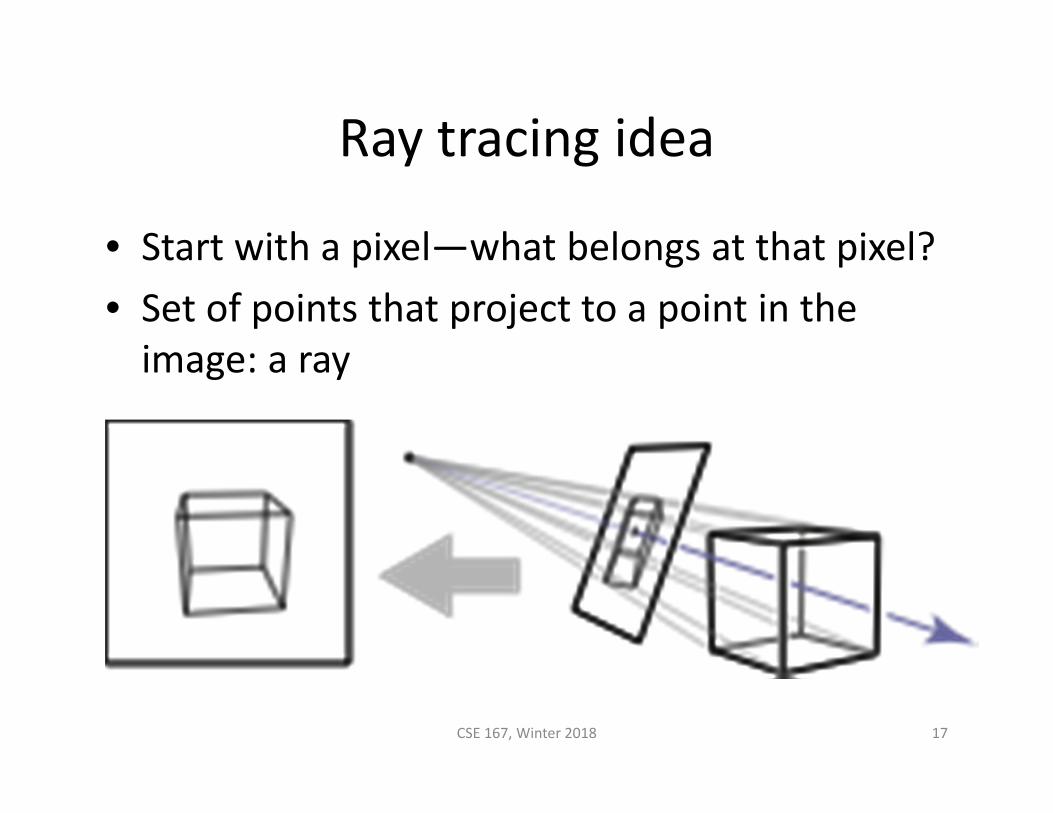
Ray tracing idea
• Start with a pixel—what belongs at that pixel?• Set of points that project to a point in the image: a ray
CSE 167, Winter 2018 17

Ray tracing idea
18CSE 167, Winter 2018

Ray tracing algorithm
for each pixel {compute viewing rayintersect ray with scenecompute illumination at visible pointput result into image
}
19CSE 167, Winter 2018

Generating eye rays, orthographic projection
• Ray origin (varying): pixel position on viewing window
• Ray direction (constant): view direction
CSE 167, Winter 2018 20

Generating eye rays, perspective projection
• Ray origin (constant): viewpoint• Ray direction (varying): toward pixel position on viewing window
CSE 167, Winter 2018 21

Software interface for cameras
• Key operation: generate ray for image position
• Modularity problem: camera should not have to worry about image resolution– Better solution: normalized coordinates
CSE 167, Winter 2018 22
class Camera {…Ray generateRay(int col, int row);
}
class Camera {…Ray generateRay(float u, float v);
}
args go from 0, 0to width – 1, height – 1
args go from 0, 0 to 1, 1

Specifying views in Ray 1
CSE 167, Winter 2018 23
<camera type="PerspectiveCamera"><viewPoint>10 4.2 6</viewPoint><viewDir>‐5 ‐2.1 ‐3</viewDir><viewUp>0 1 0</viewUp><projDistance>6</projDistance><viewWidth>4</viewWidth><viewHeight>2.25</viewHeight>
</camera>
<camera type="PerspectiveCamera"><viewPoint>10 4.2 6</viewPoint><viewDir>‐5 ‐2.1 ‐3</viewDir><viewUp>0 1 0</viewUp><projDistance>3</projDistance><viewWidth>4</viewWidth><viewHeight>2.25</viewHeight>
</camera>

Pixel‐to‐image mapping
• Mapping to normalized coordinates
CSE 167, Winter 2018 24
j
i
i = –.5
i = 3.5
j = 2.5
j = –.5
u= 0
u= 1
v = 0
v = 1

Ray intersection
25CSE 167, Winter 2018

Ray: a half line
• Standard representation: point p and direction d
– This is a parametric equation for the line– Lets us directly generate the points on the line– If we restrict to t > 0 then we have a ray– Note replacing d with αd does not change ray (α > 0)
CSE 167, Winter 2018 26
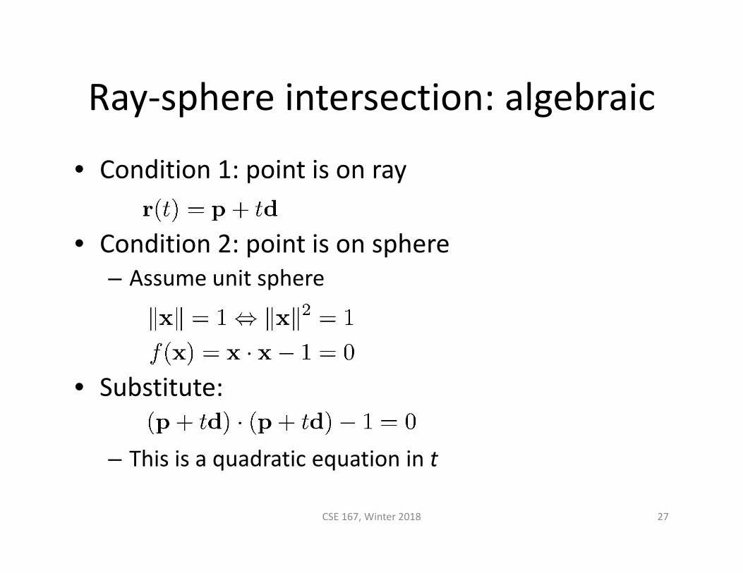
Ray‐sphere intersection: algebraic
• Condition 1: point is on ray
• Condition 2: point is on sphere– Assume unit sphere
• Substitute:
– This is a quadratic equation in t
CSE 167, Winter 2018 27

Ray‐sphere intersection: algebraic
• Solution for t by quadratic formula
– Simpler form holds when d is a unit vectorbut we will not assume this in practice
– Unit vector form is used to make the geometric interpretation (next slide)
CSE 167, Winter 2018 28

Ray‐sphere intersection: geometric
CSE 167, Winter 2018 29
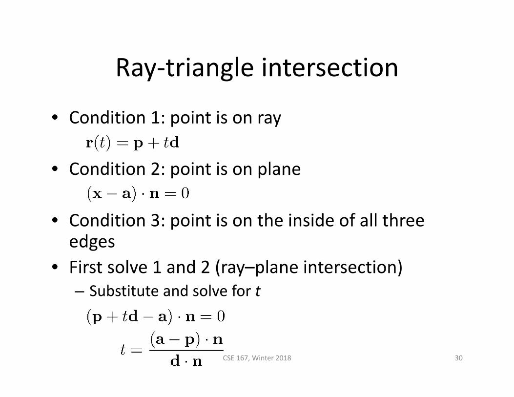
Ray‐triangle intersection
• Condition 1: point is on ray
• Condition 2: point is on plane
• Condition 3: point is on the inside of all three edges
• First solve 1 and 2 (ray–plane intersection)– Substitute and solve for t
CSE 167, Winter 2018 30

Ray‐triangle intersection
• In plane, triangle is the intersection of 3 half spaces
CSE 167, Winter 2018 31

Deciding about insideness
• Need to check whether hit point is inside 3 edges– Easiest to do in 2D coordinates on the plane
• Will also need to know where we are in the triangle– For textures, shading, etc.
• Efficient solution– Transform to coordinates aligned to the triangle
CSE 167, Winter 2018 32
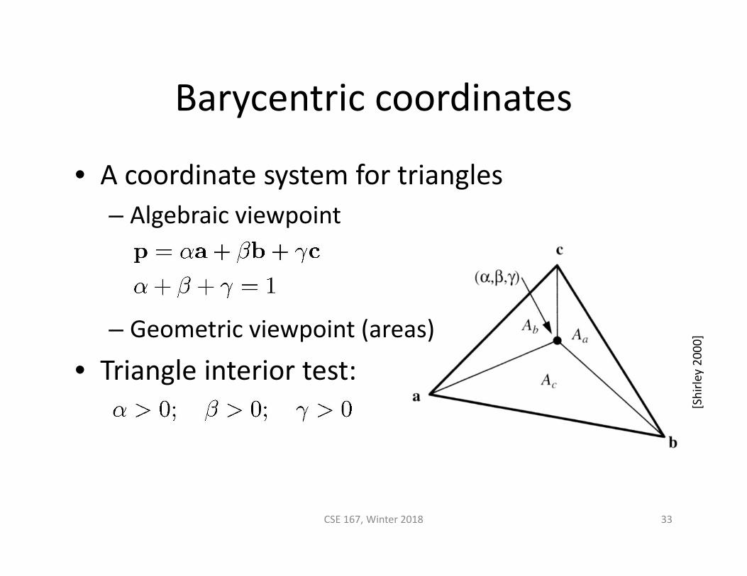
Barycentric coordinates
• A coordinate system for triangles– Algebraic viewpoint
– Geometric viewpoint (areas)
• Triangle interior test:
CSE 167, Winter 2018 33
[Shirle
y 2000]

Barycentric coordinates
• A coordinate system for triangles– Geometric viewpoint (distances)
– Linear viewpoint (basis of edges)
CSE 167, Winter 2018 34

Barycentric coordinates
• Linear viewpoint (basis for the plane)
– In this view, the triangle interior test is
CSE 167, Winter 2018 35
[Shirle
y 2000]

Barycentric ray‐triangle intersection
• Every point on the plane can be written in the form:
for some numbers β and • If the point is also on the ray then it is
for some number t• Set them equal: 3 linear equations in 3 variables
then solve them to get t, β, and
CSE 167, Winter 2018 36

Barycentric ray‐triangle intersection
CSE 167, Winter 2018 37
Cramer’s rule is a good fast way to solve this system

Ray intersection in software
• All surfaces need to be able to intersect rays with themselves
CSE 167, Winter 2018 38
class Surface {…abstract boolean intersect(IntersectionRecord result, Ray r);
}
Was there anintersection?
Information aboutfirst intersection
Ray to beintersected
class IntersectionRecord{
float t;Vector3 hitLocation;Vector3 normal;…
}
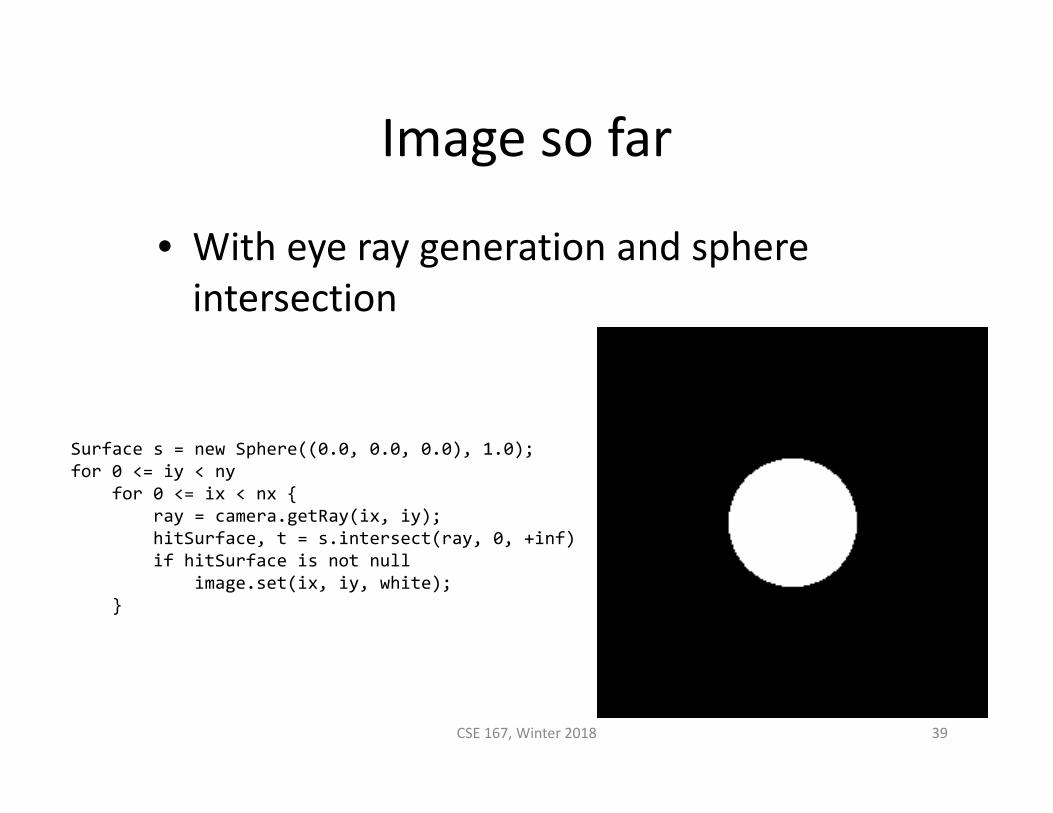
Image so far
• With eye ray generation and sphere intersection
CSE 167, Winter 2018 39
Surface s = new Sphere((0.0, 0.0, 0.0), 1.0);for 0 <= iy < ny
for 0 <= ix < nx {ray = camera.getRay(ix, iy);hitSurface, t = s.intersect(ray, 0, +inf)if hitSurface is not null
image.set(ix, iy, white);}

Ray intersection in software
• Scenes usually have many objects• Need to find the first intersection along the ray
– That is, the one with the smallest positive t value
• Loop over objects– Ignore those that do not intersect– Keep track of the closest seen so far– Convenient to give rays an endingt value for this purpose (thenthey are really segments)
CSE 167, Winter 2018 40

Intersection against many shapes• The basic idea
– This is linear in the number of shapes but there are sublinear methods (acceleration structures)
CSE 167, Winter 2018 41
intersect (ray, tMin, tMax) {tBest = +inf; firstSurface = null;for surface in surfaceList {
hitSurface, t = surface.intersect(ray, tMin, tBest);if hitSurface is not null {
tBest = t;firstSurface = hitSurface;
}}return hitSurface, tBest;
}

Summary of CSE 167• Geometric transformations• Coordinate frames• Projection and viewing• Rasterization• Surface shading: materials
and lights• Graphics pipeline• Triangle meshes• Texture mapping• Scene graph• Curves
• Culling• Environment mapping• Toon shading• Surface patches• Procedural modeling• Shadow mapping• Shadow volumes• Deferred rendering• Particle systems• Collision detection• Ray tracing
CSE 167, Winter 2018 42