Part2: Platform-based Design - EECS Instructional Support ...ee249/fa07/249secondpart... · Part2:...
24
EE249 Fall 2007 The MARCO/DARPA Gigascale Silystem Research Center for Design & Test Page 1 Part2: Platform-based Design Application Space Application Instance P Platform Design-Space Export Platform Mapping System (Software + Hardware) Platform EE249Fall06 1 Architectural Space Platform Instance Outline • Platforms: a historical perspective • Platform-based Design • Three examples – Pico-radio network – Unmanned Helicopter controller – Engine Controller EE249Fall06 2
Transcript of Part2: Platform-based Design - EECS Instructional Support ...ee249/fa07/249secondpart... · Part2:...
EE249 Fall 2007The MARCO/DARPA Gigascale SilystemResearch Center for Design & Test
Page 1
Part2: Platform-based Design
Application SpaceApplication Instance
PPlatform
Design-SpaceExport
PlatformMapping
System (Software + Hardware)Platform
EE249Fall061
Architectural SpacePlatform Instance
Outline
• Platforms: a historical perspective
• Platform-based Design
• Three examples
– Pico-radio network
– Unmanned Helicopter controller
– Engine Controller
EE249Fall062
EE249 Fall 2007The MARCO/DARPA Gigascale SilystemResearch Center for Design & Test
Page 2
Platform-Based Design Definitions:Three Perspectives
S stemSystem Designers
Semiconductor
EE249Fall063
Academic(ASV)
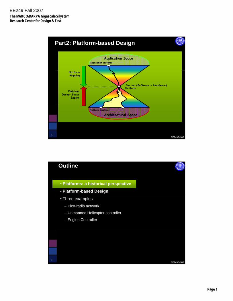
System Definition
E i ' I S i Pl f i l f h l i
EE249Fall064
Ericsson's Internet Services Platform is a new tool for helping CDMA operators and service providers deploy Mobile
Internet applications rapidly, efficiently and cost-effectivelySource: Ericsson press release
EE249 Fall 2007The MARCO/DARPA Gigascale SilystemResearch Center for Design & Test
Page 3
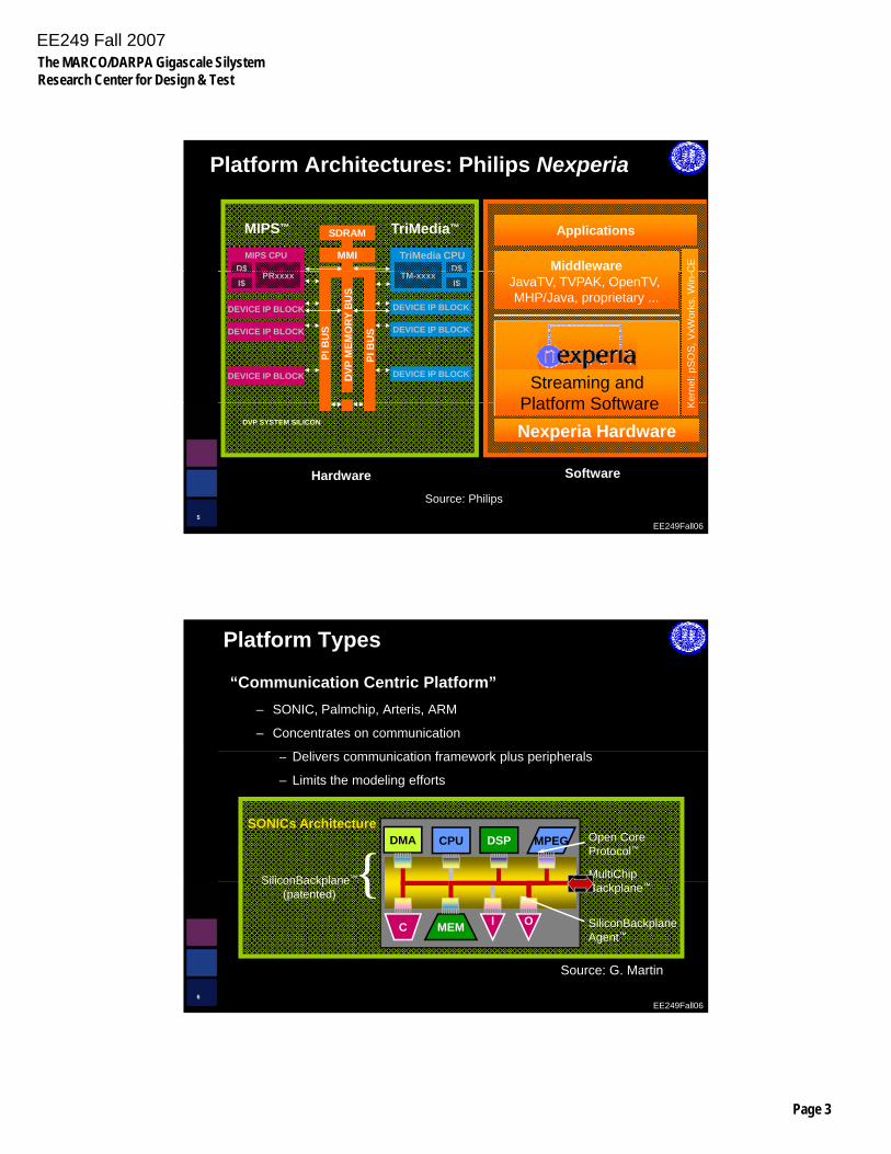
Platform Architectures: Philips Nexperia
Middleware
Applications
CED$
TriMedia CPUD$
MIPS CPU
SDRAM
MMI
TriMedia™MIPS™
JavaTV, TVPAK, OpenTV, MHP/Java, proprietary ...
Streaming andPlatform Software K
erne
l: pS
OS
, VxW
orks
, Win
-CTM-xxxx$
I$
DEVICE IP BLOCK
DEVICE IP BLOCK
DEVICE IP BLOCK
.
.
.
DEVICE IP BLOCK
PRxxxx$
I$
DEVICE IP BLOCK.
.
.DEVICE IP BLOCK
PI B
US
DVP
MEM
ORY
BU
S
PI B
US
EE249Fall065
Nexperia HardwarePlatform Software K
DVP SYSTEM SILICON
Source: Philips
Hardware Software
Platform Types
“Communication Centric Platform”– SONIC, Palmchip, Arteris, ARM
– Concentrates on communication
– Delivers communication framework plus peripherals
– Limits the modeling efforts
SiliconBackplane™{Open Core Protocol™
MultiChip
DSP MPEGCPUDMASONICs Architecture
EE249Fall066
SiliconBackplane(patented) {
SiliconBackplaneAgent™
Backplane™
C MEM I O
Source: G. Martin
EE249 Fall 2007The MARCO/DARPA Gigascale SilystemResearch Center for Design & Test
Page 4
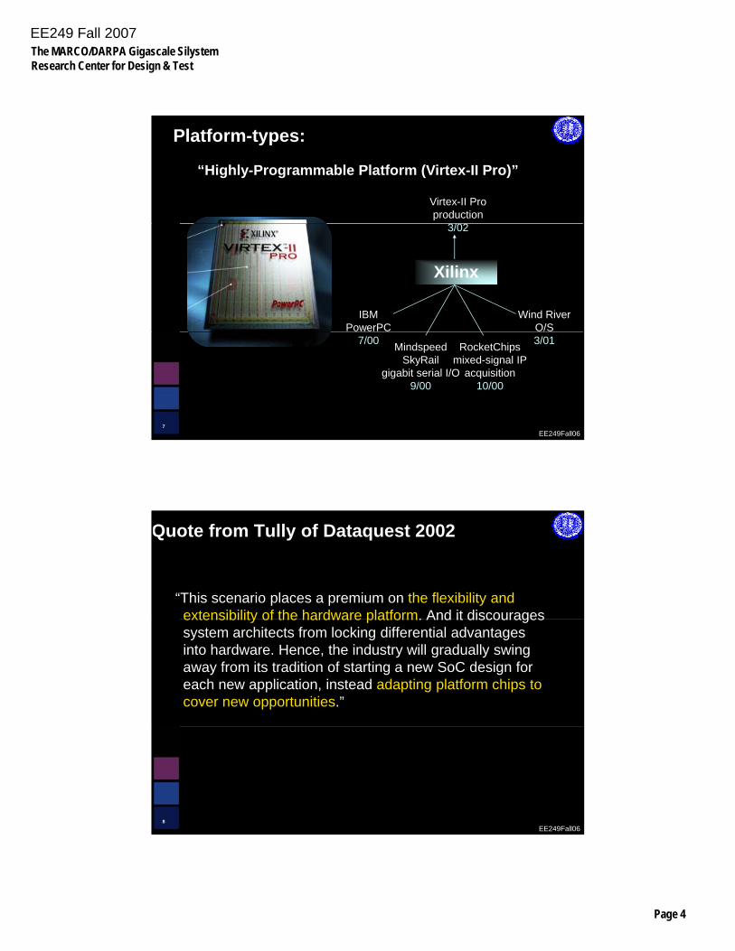
Platform-types:
Virtex-II Proproduction
3/02
“Highly-Programmable Platform (Virtex-II Pro)”
IBMPowerPC
Wind RiverO/S
3/02
Xilinx
EE249Fall067
7/00 MindspeedSkyRail
gigabit serial I/O9/00
RocketChipsmixed-signal IP
acquisition10/00
3/01
Quote from Tully of Dataquest 2002
“This scenario places a premium on the flexibility and extensibility of the hardware platform. And it discouragesextensibility of the hardware platform. And it discourages system architects from locking differential advantages into hardware. Hence, the industry will gradually swing away from its tradition of starting a new SoC design for each new application, instead adapting platform chips to cover new opportunities.”
EE249Fall068
EE249 Fall 2007The MARCO/DARPA Gigascale SilystemResearch Center for Design & Test
Page 5
Outline
• Platforms: a historical perspective
• Platform-based Design
• Three examples
– Pico-radio network
– Unmanned Helicopter controller
– Engine Controller
EE249Fall069
“Platform-Based Design” concept as a major paradigm shift for Gigascale design
“Sangiovanni-Vincentelli, a key originator of the concept, defines a platform as….."
EE249Fall0610
EETimes, 20th Year Anniversary Edition, September 12, 2002Source: Jan Rabaey
EE249 Fall 2007The MARCO/DARPA Gigascale SilystemResearch Center for Design & Test
Page 6
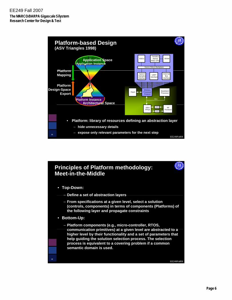
Platform-based Design(ASV Triangles 1998)
Sonics Silicon Backplane
TensilicaXtensa
RISC CPUASICs SRAM
Platform
Application SpaceApplication Instance
WirelessProcessorProtocol
BasebandProcessorFlash
Bus
SpeechSamplesInterface
UARTInterface
ExternalBus
Interface
PlatformDesign-Space
Export
PlatformMapping
Architectural SpacePlatform Instance
System (Software + Hardware)Platform
EE249Fall0611
• Platform: library of resources defining an abstraction layer– hide unnecessary details – expose only relevant parameters for the next step
Intercom Platform (BWRC, 2001)
XilinxFPGA
ADC
DAC
RFFrontend
p
Principles of Platform methodology:Meet-in-the-Middle
• Top-Down:– Define a set of abstraction layers– Define a set of abstraction layers
– From specifications at a given level, select a solution (controls, components) in terms of components (Platforms) of the following layer and propagate constraints
• Bottom-Up:– Platform components (e.g., micro-controller, RTOS,
communication primitives) at a given level are abstracted to a
EE249Fall0612
communication primitives) at a given level are abstracted to a higher level by their functionality and a set of parameters that help guiding the solution selection process. The selection process is equivalent to a covering problem if a common semantic domain is used.
EE249 Fall 2007The MARCO/DARPA Gigascale SilystemResearch Center for Design & Test
Page 7
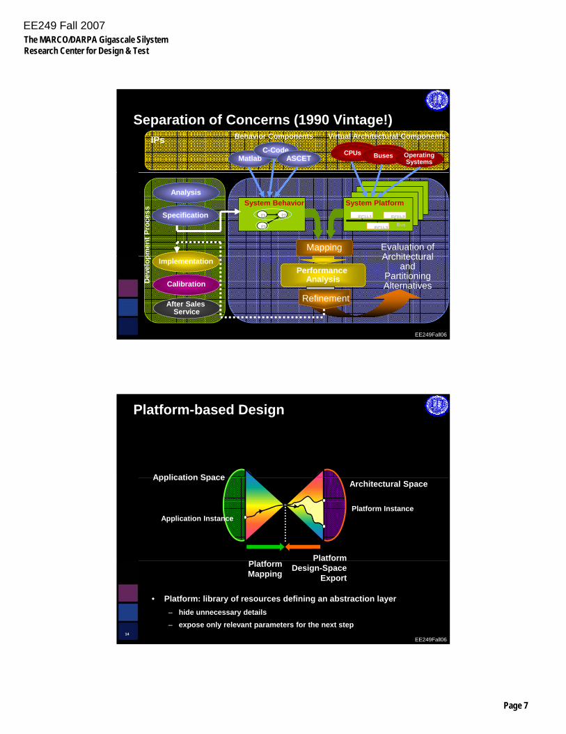
BusesBusesMatlab
CPUs Buses OperatingSystems
Behavior Components Virtual Architectural Components
C-CodeIPs
ASCET
Separation of Concerns (1990 Vintage!)
Specification
Analysis
pmen
t Pro
cess
ECUECU--11 ECUECU--22
ECUECU--33BusBus
f1f1 f2f2
f3f3
System Behavior System Platform
Mapping Evaluation ofArchitectural
EE249Fall06
After Sales Service
Calibration
Implementation
Dev
elop
Performance Analysis
Refinement
Architectural and
Partitioning Alternatives
Platform-based Design
Application Space
PlatformPl tf
Architectural SpaceApplication Space
Application InstancePlatform Instance
EE249Fall0614
• Platform: library of resources defining an abstraction layer– hide unnecessary details – expose only relevant parameters for the next step
Design-SpaceExport
PlatformMapping
EE249 Fall 2007The MARCO/DARPA Gigascale SilystemResearch Center for Design & Test
Page 8
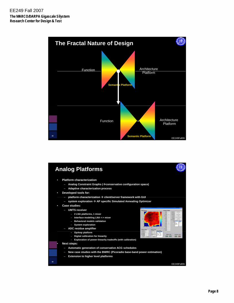
The Fractal Nature of Design
mFunction Architecture
Semantic Platform
Plat
formPlatform
EE249Fall0615 Semantic Platform
Plat
form
Function Architecture Platform
Analog Platforms• Platform characterization
– Analog Constraint Graphs ( conservative configuration space)– Adaptive characterization process
• Developed tools for:platform characterization client/server framework with GUI– platform characterization client/server framework with GUI
– system exploration AP specific Simulated Annealing Optimizer• Case studies:
– UMTS receiver– 2 LNA platforms, 1 mixer– Interface modeling LNA <-> mixer– Behavioral models validation– System exploration
– ADC residue amplifier
EE249Fall0616
– OpAmp platform– Digital calibration for linearity– Exploration of power-linearity tradeoffs (with calibration)
• Next steps:– Automatic generation of conservative ACG schedules– New case studies with the BWRC (Picoradio base-band power estimation)– Extension to higher level platforms
EE249 Fall 2007The MARCO/DARPA Gigascale SilystemResearch Center for Design & Test
Page 9
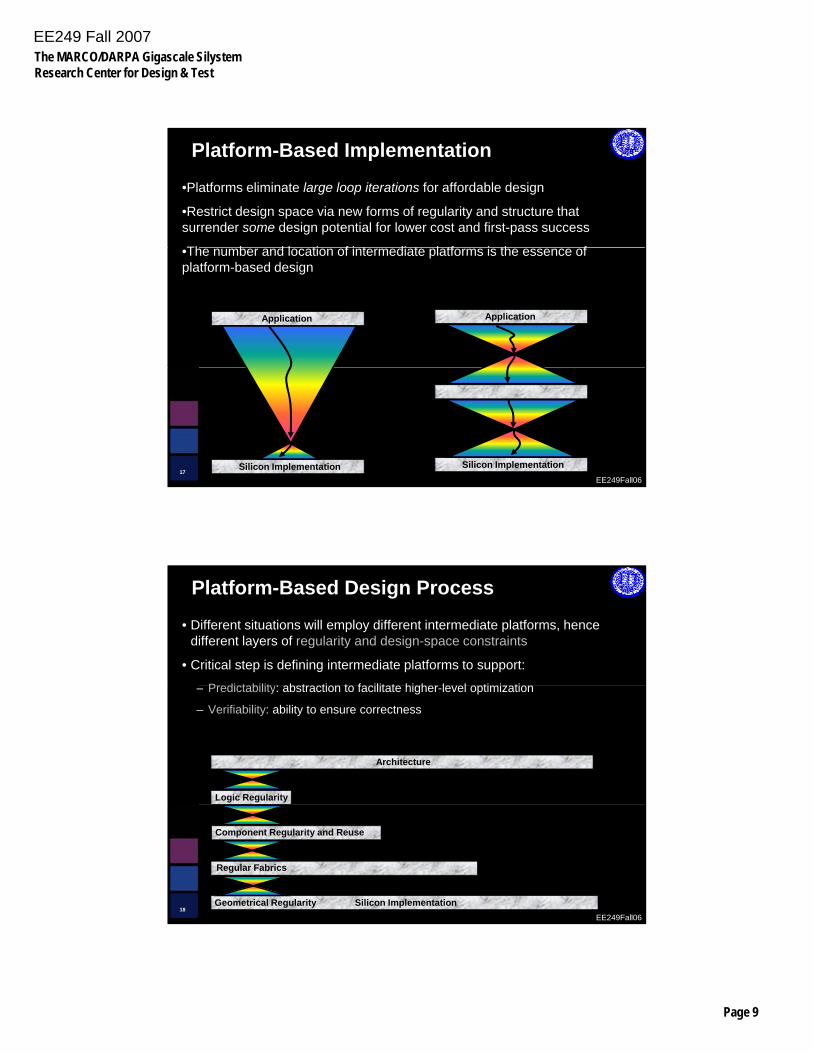
Platform-Based Implementation
•Platforms eliminate large loop iterations for affordable design
•Restrict design space via new forms of regularity and structure that surrender some design potential for lower cost and first-pass success
Th b d l ti f i t di t l tf i th f•The number and location of intermediate platforms is the essence of platform-based design
ApplicationApplication
EE249Fall0617
Silicon ImplementationSilicon Implementation
Platform-Based Design Process
• Different situations will employ different intermediate platforms, hence different layers of regularity and design-space constraints
• Critical step is defining intermediate platforms to support:
P di t bilit b t ti t f ilit t hi h l l ti i ti– Predictability: abstraction to facilitate higher-level optimization
– Verifiability: ability to ensure correctness
Architecture
Logic Regularity
EE249Fall0618
Component Regularity and Reuse
Regular Fabrics
Geometrical Regularity Silicon Implementation
EE249 Fall 2007The MARCO/DARPA Gigascale SilystemResearch Center for Design & Test
Page 10
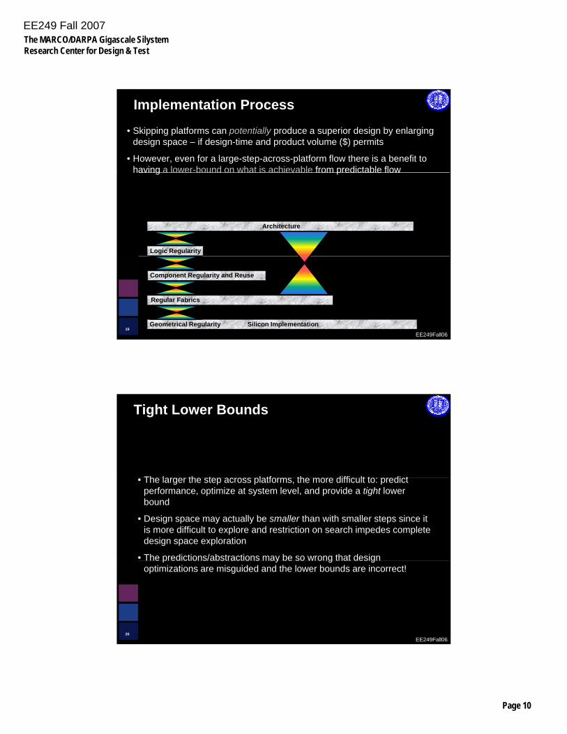
Implementation Process
• Skipping platforms can potentially produce a superior design by enlarging design space – if design-time and product volume ($) permits
• However, even for a large-step-across-platform flow there is a benefit to having a lower-bound on what is achievable from predictable flowhaving a lower bound on what is achievable from predictable flow
Architecture
Logic Regularity
EE249Fall0619
Geometrical Regularity Silicon Implementation
Component Regularity and Reuse
Regular Fabrics
Tight Lower Bounds
Th l th t l tf th diffi lt t di t• The larger the step across platforms, the more difficult to: predict performance, optimize at system level, and provide a tight lower bound
• Design space may actually be smaller than with smaller steps since it is more difficult to explore and restriction on search impedes complete design space exploration
• The predictions/abstractions may be so wrong that design
EE249Fall0620
p y g goptimizations are misguided and the lower bounds are incorrect!
EE249 Fall 2007The MARCO/DARPA Gigascale SilystemResearch Center for Design & Test
Page 11
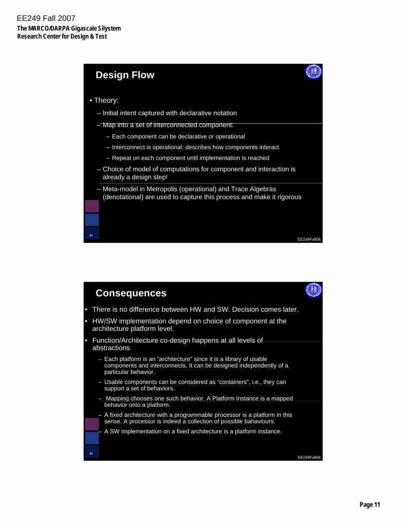
Design Flow
• Theory:
– Initial intent captured with declarative notation
M i t t f i t t d t– Map into a set of interconnected component:
– Each component can be declarative or operational
– Interconnect is operational: describes how components interact
– Repeat on each component until implementation is reached
– Choice of model of computations for component and interaction is already a design step!
EE249Fall0621
– Meta-model in Metropolis (operational) and Trace Algebras (denotational) are used to capture this process and make it rigorous
Consequences• There is no difference between HW and SW. Decision comes later.
• HW/SW implementation depend on choice of component at the architecture platform level.
• Function/Architecture co-design happens at all levels ofFunction/Architecture co design happens at all levels of abstractions
– Each platform is an “architecture” since it is a library of usable components and interconnects. It can be designed independently of a particular behavior.
– Usable components can be considered as “containers”, i.e., they can support a set of behaviors.
– Mapping chooses one such behavior. A Platform Instance is a mapped
EE249Fall0622
pp g ppbehavior onto a platform.
– A fixed architecture with a programmable processor is a platform in this sense. A processor is indeed a collection of possible bahaviours.
– A SW implementation on a fixed architecture is a platform instance.

EE249 Fall 2007The MARCO/DARPA Gigascale SilystemResearch Center for Design & Test
Page 12
A discipline for Platform-based DesignApplication
Kernels/BenchmarksProgramming Model:Models/Estimators
Architectural PlatformMicroarchitecture(s)
Circuit Fabric(s)
S SV V SG
SGS
S
V
V
SS SSVV VV SSGG
Architecture(s)
Functional Blocks,Interconnect
Cycle-speed, power, area
EE249Fall0623
Silicon Implementation PlatformManufacturing Interface
Silicon Implementation
Basic device & interconnect structures
Delay, variation,SPICE models
( ) S
Outline
• Platforms: a historical perspective
• Platform-based Design
• Three examples
– Pico-radio network
– Unmanned Helicopter controller
– Engine Controller
EE249Fall0624
EE249 Fall 2007The MARCO/DARPA Gigascale SilystemResearch Center for Design & Test
Page 13
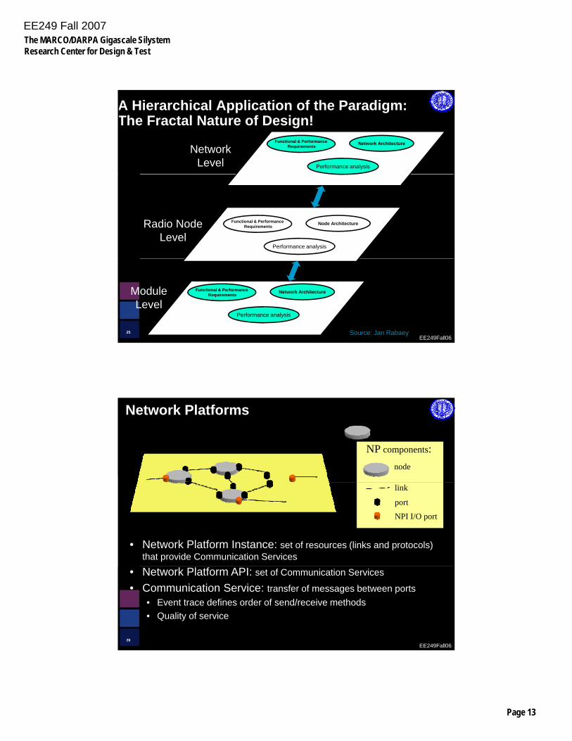
A Hierarchical Application of the Paradigm:The Fractal Nature of Design!
Functional & PerformanceRequirements Network Architecture
Performance analysis
NetworkLevel
Radio NodeLevel
Functional & PerformanceRequirements Node Architecture
Performance analysis
Constraints
EE249Fall0625
Functional & PerformanceRequirements Network Architecture
Performance analysis
ModuleLevel
Constraints
Source: Jan Rabaey
Network Platforms
node
NP components:
• Network Platform Instance: set of resources (links and protocols) that provide Communication Services
link
port
NPI I/O port
EE249Fall0626
• Network Platform API: set of Communication Services
• Communication Service: transfer of messages between ports• Event trace defines order of send/receive methods• Quality of service
EE249 Fall 2007The MARCO/DARPA Gigascale SilystemResearch Center for Design & Test
Page 14
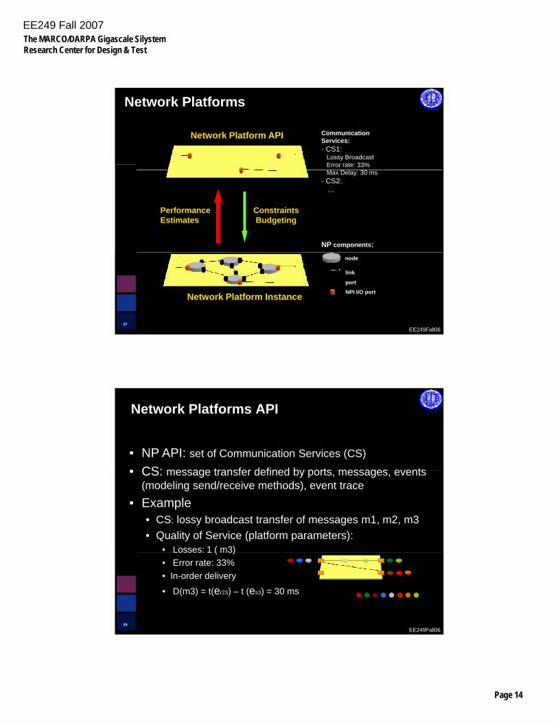
Network Platforms
CommunicationServices:- CS1:
Lossy BroadcastError rate: 33%
Network Platform API
NP components:
Max Delay: 30 ms- CS2:
…
PerformanceEstimates
ConstraintsBudgeting
EE249Fall0627
node
link
port
NPI I/O portNetwork Platform Instance
Network Platforms API
• NP API: set of Communication Services (CS)
• CS: message transfer defined by ports messages events
es1, es2, es3 er11, er12
• CS: message transfer defined by ports, messages, events (modeling send/receive methods), event trace
• Example• CS: lossy broadcast transfer of messages m1, m2, m3• Quality of Service (platform parameters):
• Losses: 1 ( m3)
EE249Fall0628
es1, es2, es3 ,
er21, er22, er23
event trace:
osses ( 3)• Error rate: 33%• In-order delivery
• D(m3) = t(er23) – t (es3) = 30 ms
EE249 Fall 2007The MARCO/DARPA Gigascale SilystemResearch Center for Design & Test
Page 15
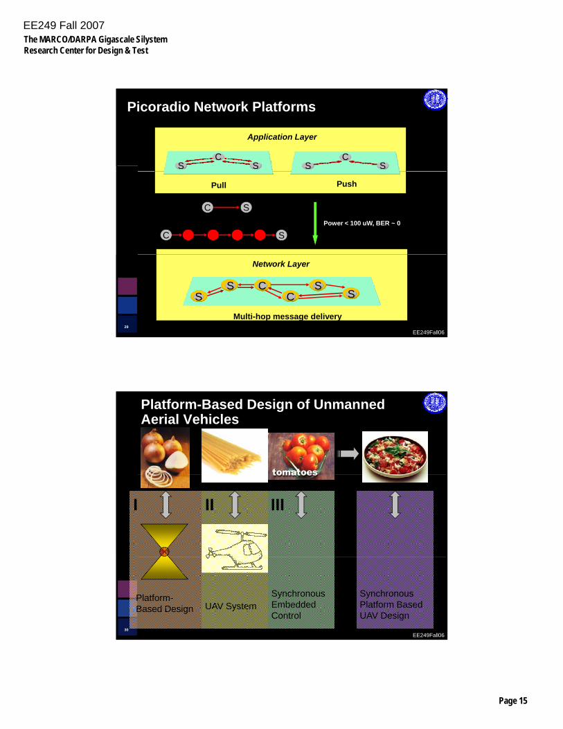
Picoradio Network Platforms
CS S
CS S
Application Layer
Pull Push
Power < 100 uW, BER ~ 0 =C S
SC
EE249Fall0629
SS C
C SS
Multi-hop message delivery
Network Layer
Platform-Based Design of Unmanned Aerial Vehicles
I II III
EE249Fall0630
Synchronous Platform Based UAV Design
Platform-Based Design UAV System
Synchronous Embedded Control
EE249 Fall 2007The MARCO/DARPA Gigascale SilystemResearch Center for Design & Test
Page 16
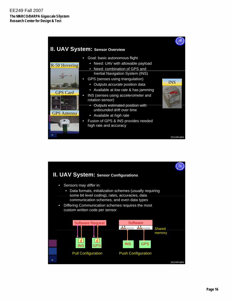
R-50 Hovering
• Goal: basic autonomous flight• Need: UAV with allowable payload• Need: combination of GPS and
II. UAV System: Sensor Overview
INS
Inertial Navigation System (INS)• GPS (senses using triangulation)
• Outputs accurate position data• Available at low rate & has jamming
• INS (senses using accelerometer and rotation sensor)• Outputs estimated position with
GPS Card
EE249Fall0631
• Outputs estimated position with unbounded drift over time
• Available at high rate• Fusion of GPS & INS provides needed
high rate and accuracy
GPS Antenna
• Sensors may differ in:• Data formats, initialization schemes (usually requiring
some bit level coding) rates accuracies data
II. UAV System: Sensor Configurations
Software Request SoftwareShared
some bit level coding), rates, accuracies, data communication schemes, and even data types
• Differing Communication schemes requires the most custom written code per sensor
EE249Fall0632
d dGPSINS GPSINS
Pull Configuration
memory
Push Configuration
EE249 Fall 2007The MARCO/DARPA Gigascale SilystemResearch Center for Design & Test
Page 17
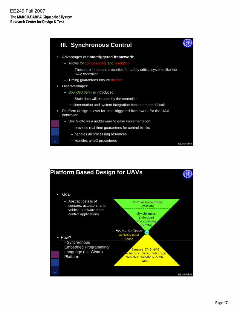
III. Synchronous Control
• Advantages of time-triggered framework: – Allows for composability and validation
– These are important properties for safety critical systems like the UAV controllerUAV controller
– Timing guarantees ensure no jitter
• Disadvantages:– Bounded delay is introduced
– Stale data will be used by the controller
– Implementation and system integration become more difficult
Pl tf d i ll f ti t i d f k f th UAV
EE249Fall0633
• Platform design allows for time-triggered framework for the UAV controller– Use Giotto as a middleware to ease implementation:
– provides real-time guarantees for control blocks
– handles all processing resources
– Handles all I/O procedures
Platform Based Design for UAVs
Control Applications (M tl b)
• Goal
– Abstract details of sensors actuators and (Matlab)sensors, actuators, and vehicle hardware from control applications
Application SpaceArchitectural
Space
Synchronous Embedded
Programming(Giotto)
• How?
EE249Fall0634
Sensors: INS, GPSActuators: Servo InterfaceVehicles: Yamaha R-50/R-
Max
p- Synchronous Embedded Programming Language (i.e. Giotto) Platform
EE249 Fall 2007The MARCO/DARPA Gigascale SilystemResearch Center for Design & Test
Page 18
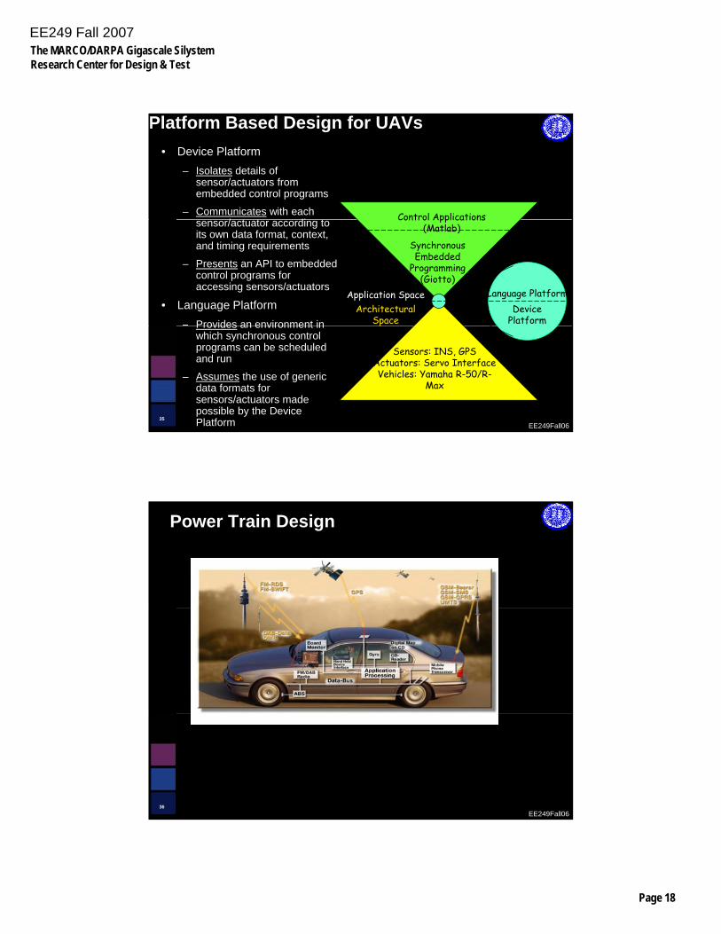
Platform Based Design for UAVs• Device Platform
– Isolates details of sensor/actuators from embedded control programs
– Communicates with each / t t di t Control Applications sensor/actuator according to
its own data format, context, and timing requirements
– Presents an API to embedded control programs for accessing sensors/actuators
• Language Platform– Provides an environment in
Synchronous Embedded
Programming(Giotto)
Control Applications (Matlab)
Application SpaceArchitectural
SpaceDevice
Platform
Language Platform
EE249Fall0635
Provides an environment in which synchronous control programs can be scheduled and run
– Assumes the use of generic data formats for sensors/actuators made possible by the Device Platform
Sensors: INS, GPSActuators: Servo InterfaceVehicles: Yamaha R-50/R-
Max
p
Virtual Avionics Platform
Power Train Design
EE249Fall0636
EE249 Fall 2007The MARCO/DARPA Gigascale SilystemResearch Center for Design & Test
Page 19
The Design Problem
Given a set of specifications from a car manufacturerGiven a set of specifications from a car manufacturer,
– Find a set of algorithm to control the power train
– Implement the algorithms on a mixed mechanical-electrical architecture (microprocessors, DSPs, ASICs, various sensors and actuators)
EE249Fall0637
Power-train control system design
• Specifications given at a high level of abstractionSpecifications given at a high level of abstraction
• Control algorithms design
• Mapping to different architectures using performance estimation techniques and automatic code generation from models
• Mechanical/Electronic architecture selected among a set of
EE249Fall0638
candidates
EE249 Fall 2007The MARCO/DARPA Gigascale SilystemResearch Center for Design & Test
Page 20
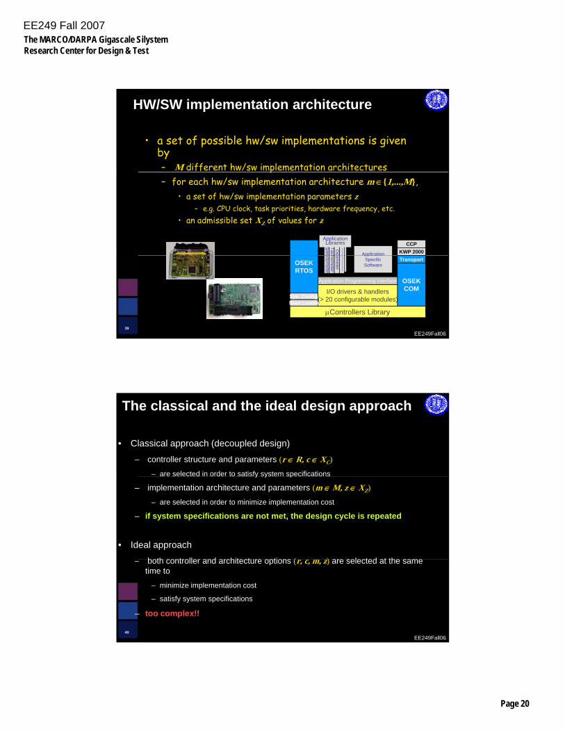
HW/SW implementation architecture
• a set of possible hw/sw implementations is given by– M different hw/sw implementation architecturesp– for each hw/sw implementation architecture m ∈{1,...,M},
• a set of hw/sw implementation parameters z– e.g. CPU clock, task priorities, hardware frequency, etc.
• an admissible set XZ of values for z
KWP 2000CCP
Application
SpeedTachW
ate
SpeeTacO
d-----
ApplicationLibraries
CustomerLibraries
EE249Fall0639
μControllers Library
OSEKRTOS
OSEKCOMI/O drivers & handlers
(> 20 configurable modules)
Application Programming Interface
Boot LoaderSys. Config.
TransportApplication
SpecificSoftware
dometer
hometer
er temp.
edometer
hometer
ometer
-----------
The classical and the ideal design approach
• Classical approach (decoupled design)
– controller structure and parameters (r ∈ R, c ∈ XC)
– are selected in order to satisfy system specificationsa e se ected o de to sat s y syste spec cat o s
– implementation architecture and parameters (m ∈ M, z ∈ XZ)
– are selected in order to minimize implementation cost
– if system specifications are not met, the design cycle is repeated
• Ideal approach
both controller and architecture options ( ) are selected at the same
EE249Fall0640
– both controller and architecture options (r, c, m, z) are selected at the same time to
– minimize implementation cost
– satisfy system specifications
– too complex!!
EE249 Fall 2007The MARCO/DARPA Gigascale SilystemResearch Center for Design & Test
Page 21
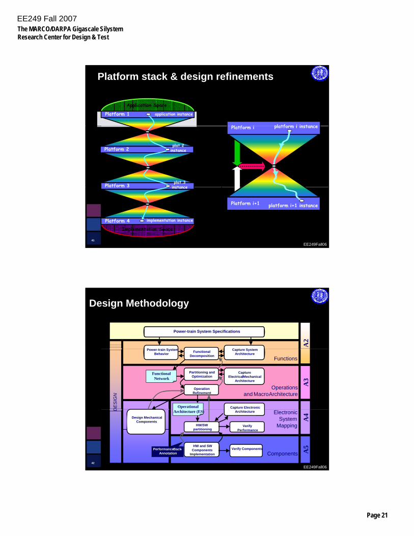
Platform stack & design refinements
Application Space
Platform 1 application instance
Pl tf i platform i instance
PlatformDesign-Space
Export
PlatformMapping
Refinement
Platform 3
Platform 2
plat.3 instance
plat.2 instance
Platform i platform i instance
EE249Fall0641
Platform i+1
p
Implementation SpacePlatform 4
Platform 3
implementation instance
instance
platform i+1 instance
P t i S t
Power-train System Specifications
C t S t
A2
Design Methodology
DE
SIG
N
Power-train SystemBehavior Functional
Decomposition
Capture SystemArchitecture
Operationsand MacroArchitecture
Functions
Capture Electronic
OperationRefinement
CaptureElectrical/Mechanical
Architecture
Partitioning andOptimization
Functional Network
Operational
A3
EE249Fall0642
D ElectronicSystem
Mapping
PerformanceBack-Annotation
HW and SWComponents
Implementation ComponentsVerify Components
Architecture
HW/SWpartitioning
Design MechanicalComponents
Architecture (ES)
VerifyPerformance
A4
A5
EE249 Fall 2007The MARCO/DARPA Gigascale SilystemResearch Center for Design & Test
Page 22
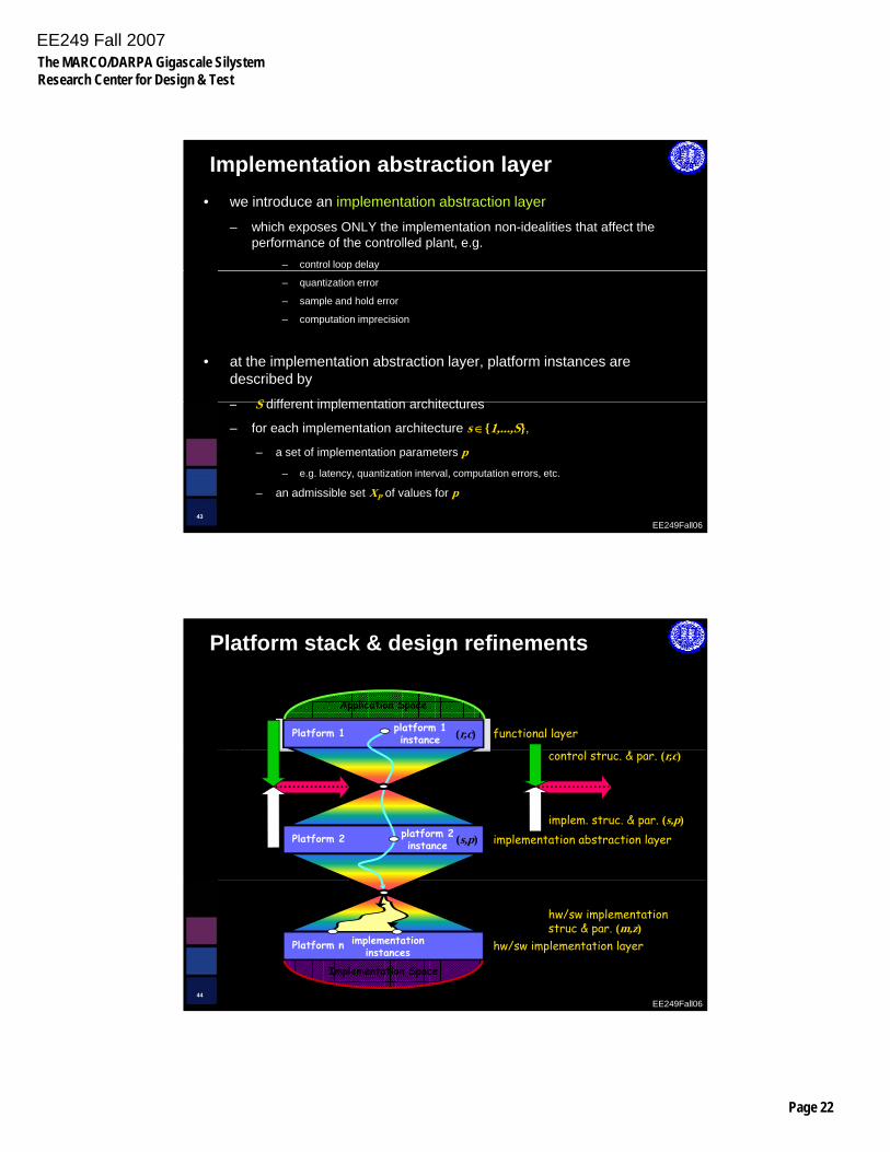
Implementation abstraction layer• we introduce an implementation abstraction layer
– which exposes ONLY the implementation non-idealities that affect the performance of the controlled plant, e.g.
– control loop delay
– quantization error
– sample and hold error
– computation imprecision
• at the implementation abstraction layer, platform instances are described by
S different implementation architectures
EE249Fall0643
– S different implementation architectures
– for each implementation architecture s ∈{1,...,S},
– a set of implementation parameters p
– e.g. latency, quantization interval, computation errors, etc.
– an admissible set XP of values for p
Pl tf
Platform stack & design refinements
Application Space
Platform 1 platform 1instance functional layer(r,c)
PlatformDesign-Space
Export
PlatformMapping
Platform 2 platform 2instance
Refinement
implementation abstraction layerimplem. struc. & par. (s,p)
control struc. & par. (r,c)
(r,c,s,p)
(s,p)
(r,c,s,p)
EE249Fall0644
Implementation Space
Platform n implementationinstances hw/sw implementation layer
hw/sw implementationstruc & par. (m,z)
EE249 Fall 2007The MARCO/DARPA Gigascale SilystemResearch Center for Design & Test
Page 23
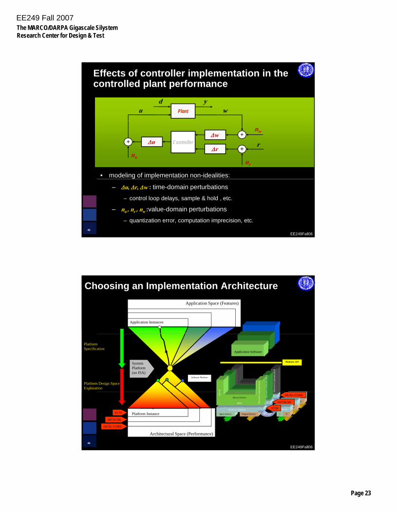
Effects of controller implementation in the controlled plant performance
d y Plant wu
Controller rΔw
Δr Δu +
nu
+
+
nr
nw
• modeling of implementation non-idealities:
EE249Fall0645
– Δu, Δr, Δw : time-domain perturbations
– control loop delays, sample & hold , etc.
– nu , nr , nw :value-domain perturbations
– quantization error, computation imprecision, etc.
Application Space (Features)
Choosing an Implementation Architecture
Application Instances
Application Software
RTO
S
BIOS
Device Drivers
Net
wor
k C
omm
unic
atio
n
System Platform(no ISA)
Platform Design Space Exploration
PlatformSpecification
Platform API
Software Platform
RTO
S
Device Drivers rk C
omm
unic
atio
n
OS
mm
unic
atio
n
OS
mm
unic
atio
n
Application Software
EE249Fall0646
Output DevicesInput devices
Hardware Platform
I O
Hardware
network
DUAL-CORE
BIOS N
DUAL-CORE
Architectural Space (Performance)
Platform Instance
Output DevicesInput devices
Hardware Platform
I O
Hardware
network
HITACHI
BIOS
Device Drivers
Net
wor
HITACHI
RTO
BIOS
Device Drivers
Net
wor
k C
om
Output DevicesInput devices
Hardware Platform
I O
Hardware
network
ST10
RTO
BIOS
Device Drivers
Net
wor
k C
om
ST10
EE249 Fall 2007The MARCO/DARPA Gigascale SilystemResearch Center for Design & Test
Page 24
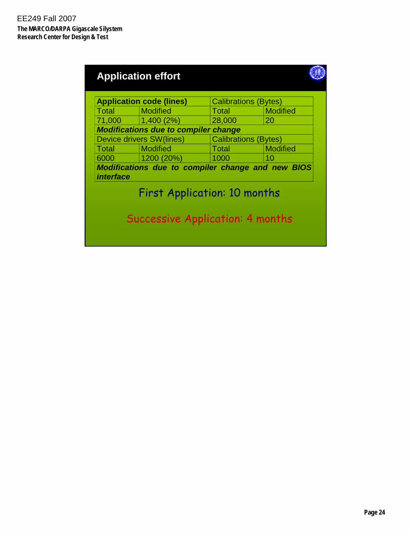
Application effort
Application code (lines) Calibrations (Bytes) Total Modified Total Modified 71,000 1,400 (2%) 28,000 20 Modifications due to compiler changeDevice drivers SW(lines) Calibrations (Bytes) Total Modified Total Modified 6000 1200 (20%) 1000 10 Modifications due to compiler change and new BIOS interface
EE249Fall0647
First Application: 10 months
Successive Application: 4 months