PART1. GNS3 Installation & Settings - Donald Bren …magda/ics_x33/lab1.pdfPART1. GNS3 Installation...
19
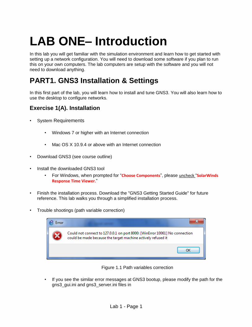
Lab 1 - Page 1 LAB ONE– Introduction In this lab you will get familiar with the simulation environment and learn how to get started with setting up a network configuration. You will need to download some software if you plan to run this on your own computers. The lab computers are setup with the software and you will not need to download anything. PART1. GNS3 Installation & Settings In this first part of the lab, you will learn how to install and tune GNS3. You will also learn how to use the desktop to configure networks. Exercise 1(A). Installation • System Requirements • Windows 7 or higher with an Internet connection • Mac OS X 10.9.4 or above with an Internet connection • Download GNS3 (see course outline) • Install the downloaded GNS3 tool • For Windows, when prompted for “Choose Components”, please uncheck “SolarWinds Response Time Viewer.” • Finish the installation process. Download the "GNS3 Getting Started Guide" for future reference. This lab walks you through a simplified installation process. • Trouble shootings (path variable correction) Figure 1.1 Path variables correction • If you see the similar error messages at GNS3 bootup, please modify the path for the gns3_gui.ini and gns3_server.ini files in
Transcript of PART1. GNS3 Installation & Settings - Donald Bren …magda/ics_x33/lab1.pdfPART1. GNS3 Installation...
Lab 1 - Page 1
LAB ONE– Introduction In this lab you will get familiar with the simulation environment and learn how to get started with setting up a network configuration. You will need to download some software if you plan to run this on your own computers. The lab computers are setup with the software and you will not need to download anything.
PART1. GNS3 Installation & Settings In this first part of the lab, you will learn how to install and tune GNS3. You will also learn how to use the desktop to configure networks.
Exercise 1(A). Installation
• System Requirements
• Windows 7 or higher with an Internet connection
• Mac OS X 10.9.4 or above with an Internet connection
• Download GNS3 (see course outline)
• Install the downloaded GNS3 tool
• For Windows, when prompted for “Choose Components”, please uncheck “SolarWinds Response Time Viewer.”
• Finish the installation process. Download the "GNS3 Getting Started Guide" for future reference. This lab walks you through a simplified installation process.
• Trouble shootings (path variable correction)
Figure 1.1 Path variables correction
• If you see the similar error messages at GNS3 bootup, please modify the path for the gns3_gui.ini and gns3_server.ini files in

Lab 1 - Page 2
C:\Users\$(username)\AppData\Roaming\GNS3. Make sure you have write permission to the entire path specified in those .ini files.
Exercise 1(B). Settings 1. Open GNS3 and go to Edit -> Preferences on Windows or GNS3 -> Preferences on Mac 2. Click on the arrow next to Dynamips and then click on the sub-menu “IOS routers”.
3. First download the cisco IOS image “c2600-ik8o3s-mz.122-11.T.bin’’ from UCI-ICS
masterhit network drive with the following server names:
a) Windows: \\masterhit.ics.uci.edu\network_lab b) Mac: smb://masterhit.ics.uci.edu/network_lab
To learn more about mapping “UCI-ICS masterhit network drive”, please click Windows or Mac.A VPN client might be necessary to access the UCI network drive from outside of UCI campus. 4. Then click on New, then on Browse to select the Cisco IOS image on your computer.
Change the Chassis to 2611XM as shown in Figure 1.1 below.
Figure 1.2 Cisco router import
5. Click on next and check to see if memory size is set to 64Mb, if not set it to that size. Please
note that the memory size configuration is strict. Setting memory more than 64 Mb causes problem as well.
6. Click on Next until you get to WIC modules selection as shown in Figure 1.2 below. Choose WIC-1T from the menu for wic 0.
Lab 1 - Page 3
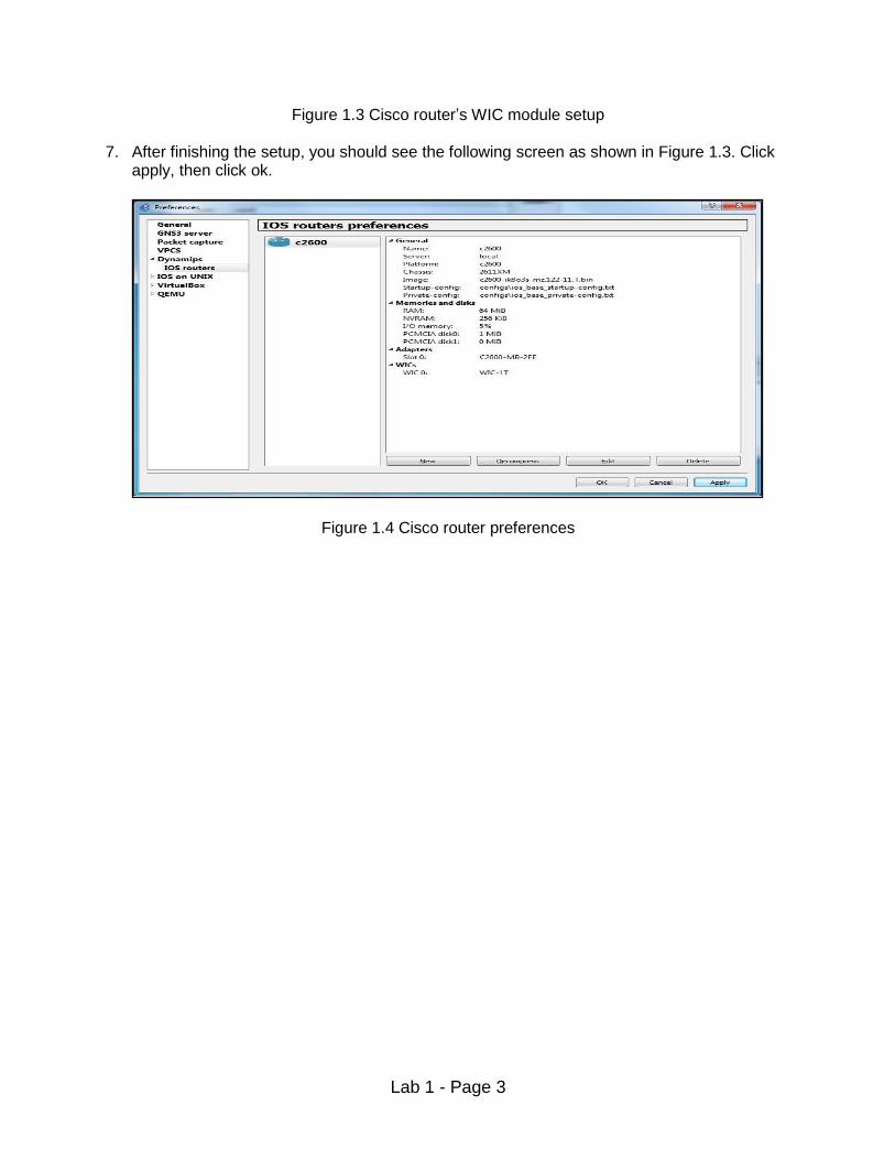
Figure 1.3 Cisco router’s WIC module setup 7. After finishing the setup, you should see the following screen as shown in Figure 1.3. Click
apply, then click ok.
Figure 1.4 Cisco router preferences

Lab 1 - Page 4
8. In the GNS3 console window, click on the 5th icon down on the left hand side to browse all devices. Select c2600 and drag it to the empty area on the right as shown in Figure 1.4.
Figure 1.5 How to add a router to the GNS3 desktop 9. Right-click the Taskbar (or cltr+alt+del), and choose Task Manager. You will need to monitor
the CPU load when you start a router. If the CPU load goes to 100%, then you will need to stop GNS3, then restart it and repeat the above router selection routine. If not proceed with step 10.
10. Right-click on R1 and choose Start. 11. Right-click on R1 and choose Console. Press Return key if it asks you to so that you get to
the prompt line. 12. The CPU load in the Task Manager should stay low after starting the router. If it doesn’t,
then follow Steps 13-14. If the load is low (25% or less), go to PART2.

Lab 1 - Page 5
13. Right-click on R1 and choose Idle-PC. A window with a dropdown box will appear. Select a value with an * next to it as shown in Figure 1.5 below.
Figure 1.6 Idle PC value settings window
14. Continue to right-click on R1 and choose Idle-PC until the pop up window doesn’t have any more values with an * next to it. Hopefully, this will keep the CPU low when the routers are started. If the CPU remains high, close GNS3 and try starting again.

Lab 1 - Page 6
PART 2. Virtual Box Installation (with Ubuntu) For this lab and some of the later ones, we will be using virtual machines to conduct our network configurations. To do this, we will need to install Virtual Box and Ubuntu.
Exercise 2(A). Installation of UBUNTU 1. Same system requirements as for GNS3.
2. Download Virtual Box (see course outline); according to the platform you are using
(Windows, OS, Linux, etc…) follow the instructions as listed for installation (use default
settings).
3. Download Ubuntu image “ubuntu_CSx33.ova” from UCI-ICS masterhit network drive and
place the download on your desktop or somewhere that is easily accessible. Note that this is a server version of Ubuntu created specifically for this class. Ubuntu is a spin off from Linux. As such, we will refer to all the OS commands in the Labs as "Linux" commands.
Lab 1 - Page 7
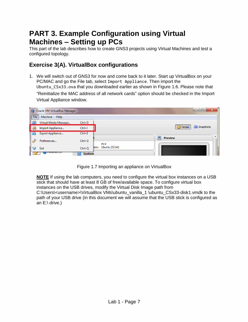
PART 3. Example Configuration using Virtual Machines – Setting up PCs This part of the lab describes how to create GNS3 projects using Virtual Machines and test a configured topology.
Exercise 3(A). VirtualBox configurations 1. We will switch out of GNS3 for now and come back to it later. Start up VirtualBox on your
PC/MAC and go the File tab, select Import Appliance. Then import the
Ubuntu_CSx33.ova that you downloaded earlier as shown in Figure 1.6. Please note that
“Reinitialize the MAC address of all network cards” option should be checked in the Import
Virtual Appliance window.
Figure 1.7 Importing an appliance on VirtualBox NOTE If using the lab computers, you need to configure the virtual box instances on a USB stick that should have at least 8 GB of free/available space. To configure virtual box instances on the USB drives, modify the Virtual Disk Image path from C:\Users\<username>\VirtualBox VMs\ubuntu_vanilla_1 \ubuntu_CSx33-disk1.vmdk to the path of your USB drive (in this document we will assume that the USB stick is configured as an E:\ drive.)

Lab 1 - Page 8
Figure 1.8 Virtual Disk path corrections (Optional)
2. This will take a few minutes. After the process finishes, you should have a virtual machine called Ubuntu. For the sake of simplicity and conforming with the naming conventions we are using in the Labs, you should rename it to PC1 via the settings tab.
3. Start PC1 on VirtualBox. The username is user and password is password. This is the
default login information. Then, type sudo su. When it asks for the password, type
password again. Now you are in ADMIN mode. That means you have root privileges.
4. After you have completed the above steps, shutdown PC1. Go to settings and click the
Network tab and change the adapter setting to Not Attached as shown in Figure 1.8. This
configuration allows GNS3 to manage the device for simulations. Click ok when finished
Figure 1.9 Network settings on VirtualBox

Lab 1 - Page 9
5. PC1 should be set up in VirtualBox as shown in Figure 1.9.
Figure 1.10 PC1 configuration on VirtualBox
6. Emulating virtual machines requires the allocation of resources from your current system. It is important to monitor how much resources you can allocate to an emulation.

Lab 1 - Page 10
Figure 1.11 “Clone Virtual Machine” Window for PC2, PC3 and PC4
Now that you have successfully set up your first virtual machine, named PC1, running Ubuntu, a Linux spinoff OS, you can create many other PC’s (virtual machines or VMs), by simply right clicking on an existing VM, i.e., PC1, and selecting the clone option, check “Reinitialize the
MAC address of all network cards” option and name it accordingly (e.g. PC2, PC3, etc.). All future labs will need a maximum of 4 PCs, so it is highly recommended to create a total of 4 PCs by cloning PC1. 7. Create 3 more virtual machine named PC2, PC3 and PC4.. NOTE: To configure more VirtualBox instances on a USB stick, follow Step 1 through Step 6 for PC2, PC3 and PC4. Cloning PC1 is NOT an option.

Lab 1 - Page 11
APPENDIX to Exercise 3A: WORKING ON LAB COMPUTERS Instructions to create virtual machines (VMs), port them to a USB stick and import into Virtualbox
1. Once you create four instances of VMs on the computer (PC1, PC2, PC3, PC4), find the .vmdk files corresponding to each VM and save it on a USB stick. This will require at least 8 GB space in your USB stick. Then, connect the USB stick to the host PC (Windows, Linux or Mac) you are running the Virtual box in and follow the steps below.
2. Click New in VirtualBox and select the type as ‘Linux’ and name it as PC1 as shown
below:
Figure A.1 Creating a new virtual machine
3. Click on Next for default memory size as shown below:

Lab 1 - Page 12
Figure A.2 Virtual machine memory setup
4. Then in the next screen when it asks to select a Hard Disk, select ‘Use an existing virtual
hard disk file’, click to browse and load the .vmdk file for PC1 from your USB stick. Then click ‘create’:
Figure A.3 How to refer an existing virtual drive

Lab 1 - Page 13
5. The VM for PC1 will be created as shown below. Follow the same steps for creating PC2, PC3 and PC4:
Figure A.4 Screenshot when it is done
Lab 1 - Page 14
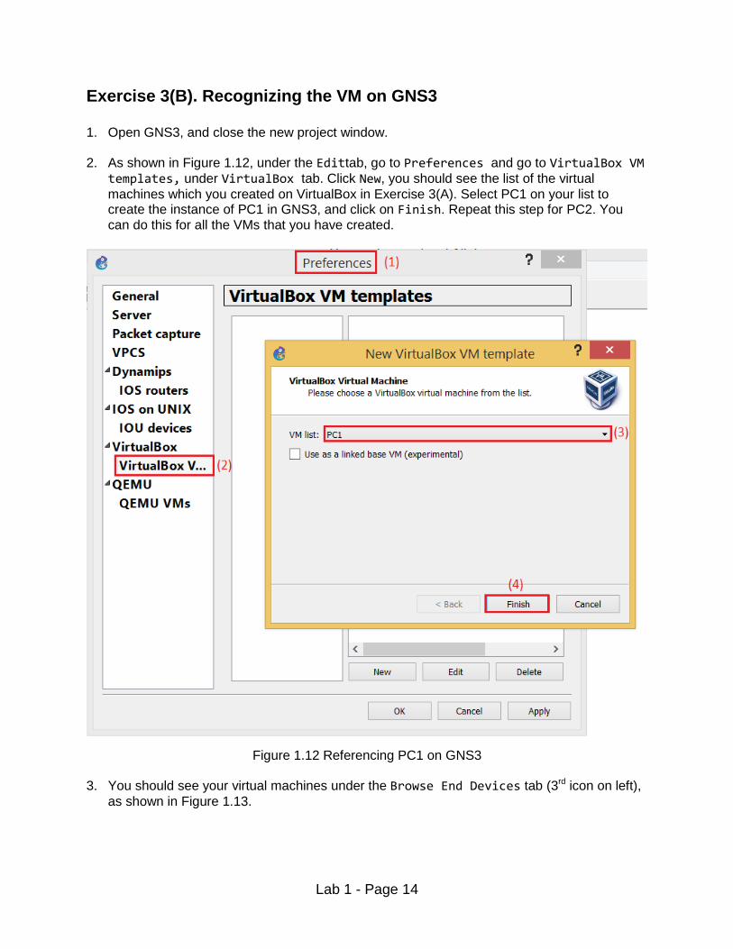
Exercise 3(B). Recognizing the VM on GNS3
1. Open GNS3, and close the new project window.
2. As shown in Figure 1.12, under the Edittab, go to Preferences and go to VirtualBox VM
templates, under VirtualBox tab. Click New, you should see the list of the virtual
machines which you created on VirtualBox in Exercise 3(A). Select PC1 on your list to create the instance of PC1 in GNS3, and click on Finish. Repeat this step for PC2. You
can do this for all the VMs that you have created.
Figure 1.12 Referencing PC1 on GNS3
3. You should see your virtual machines under the Browse End Devices tab (3rd icon on left),
as shown in Figure 1.13.

Lab 1 - Page 15
Figure 1.13 Finding VMs on GNS3
4. Set up PC1 and PC2 in the project to start a network simulation as shown in Figure 1.14.This is done by selecting a VM and dragging it to the empty project pane on the right side of the window.
Figure 1.14 PC1 and PC2 in a GNS3 project 5. In GNS3, click on the 6th icon down on the left hand side to activate the Add a link
feature. Note that the 6th icon will change to an icon with “X” mark. Click on PC1 and select
Ethernet0 as shown in Figure 1.15. Then repeat the process for PC2. You can press esc or
click the 6thicon to exit the link feature.
Lab 1 - Page 16
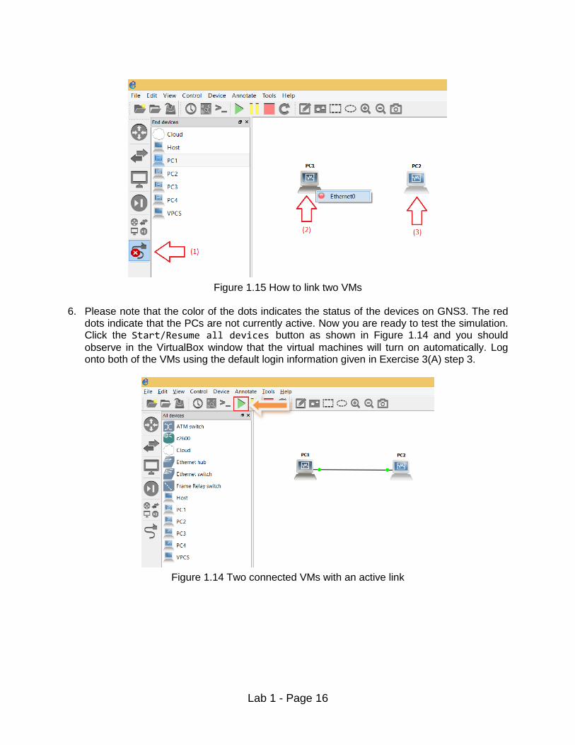
Figure 1.15 How to link two VMs 6. Please note that the color of the dots indicates the status of the devices on GNS3. The red
dots indicate that the PCs are not currently active. Now you are ready to test the simulation. Click the Start/Resume all devices button as shown in Figure 1.14 and you should
observe in the VirtualBox window that the virtual machines will turn on automatically. Log onto both of the VMs using the default login information given in Exercise 3(A) step 3.
Figure 1.14 Two connected VMs with an active link
Lab 1 - Page 17
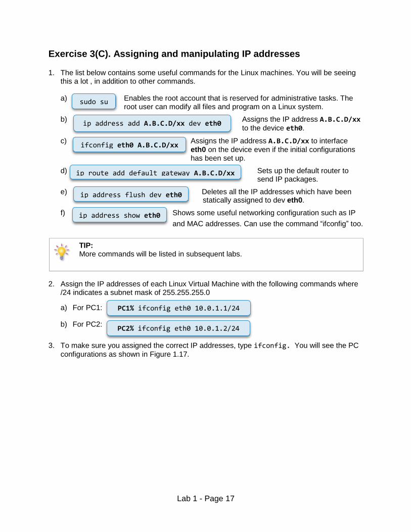
Exercise 3(C). Assigning and manipulating IP addresses 1. The list below contains some useful commands for the Linux machines. You will be seeing
this a lot , in addition to other commands.
a) Enables the root account that is reserved for administrative tasks. The root user can modify all files and program on a Linux system.
b) Assigns the IP address A.B.C.D/xx to the device eth0.
c) Assigns the IP address A.B.C.D/xx to interface
eth0 on the device even if the initial configurations has been set up.
d) Sets up the default router to send IP packages.
e) Deletes all the IP addresses which have been statically assigned to dev eth0.
f) Shows some useful networking configuration such as IP
and MAC addresses. Can use the command “ifconfig” too.
TIP: More commands will be listed in subsequent labs.
2. Assign the IP addresses of each Linux Virtual Machine with the following commands where
/24 indicates a subnet mask of 255.255.255.0
a) For PC1:
b) For PC2:
3. To make sure you assigned the correct IP addresses, type ifconfig. You will see the PC
configurations as shown in Figure 1.17.
sudo su
ip address add A.B.C.D/xx dev eth0
ip route add default gateway A.B.C.D/xx
ip address flush dev eth0
ip address show eth0
PC1% ifconfig eth0 10.0.1.1/24
PC2% ifconfig eth0 10.0.1.2/24
ifconfig eth0 A.B.C.D/xx

Lab 1 - Page 18
Figure 1.17 ifconfig output
Exercise 3(D). Using the command Ping
One of the most basic, but also most effective tools to debug IP networks is the ping command.
The ping command tests whether another host or router on the Internet is reachable. The ping
command sends an ICMP Echo Request datagram to an interface and expects an ICMP Echo Replay datagram in return. A few pingusage scenarios are listed below.
ISSUING PING COMMANDS When using ping on the Linux PCs, we recommend to always send at least two
ICMP Echo Request packets. We have observed that the first ICMP Echo Request may often be dropped at a router due to the ARP protocol.
1. From PC1, send five ping messages (using the -c option) to PC2. On PC1, this is done by
typing
2. From PC2, send five ping messages to PC1.
COMMON USES OF THE PING COMMAND
ping IPaddress Issues a ping command for the host with the given IP address. The system will issue one ICMP Echo Request packet with a size of 56 bytes every second. The command is stopped by pressing Ctrl-C.
ping IPaddress–c num
The command stops after sending a number, num, of ICMP Echo Requests.
ping IPaddress –s num The number of data bytes in the ICMP Echo Request is set to num bytes.
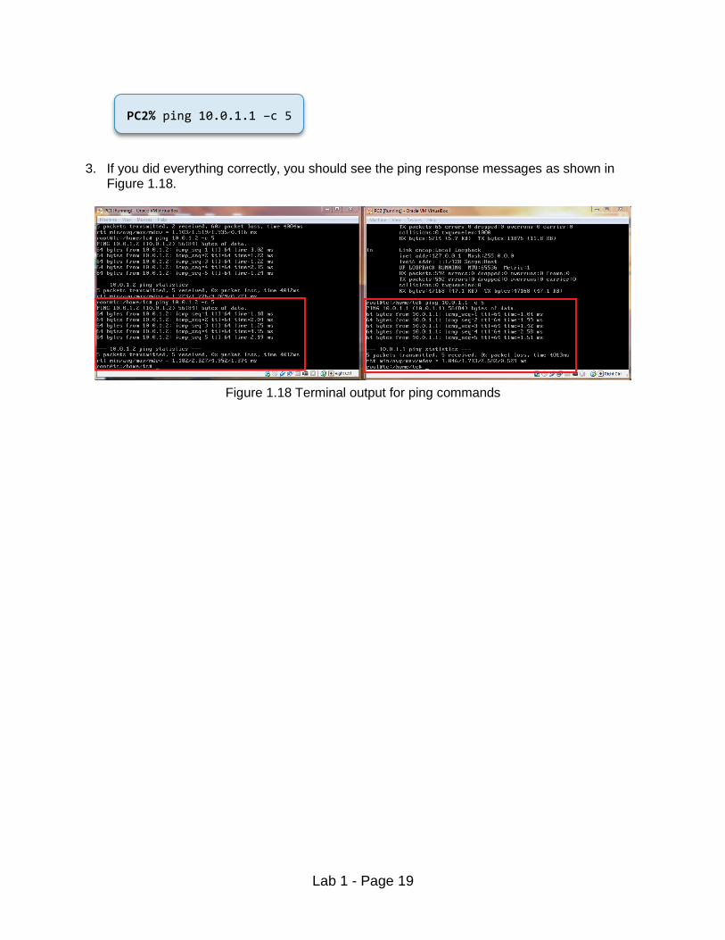
PC1% ping 10.0.1.2 –c 5
Lab 1 - Page 19
3. If you did everything correctly, you should see the ping response messages as shown in
Figure 1.18.
Figure 1.18 Terminal output for ping commands
PC2% ping 10.0.1.1 –c 5