Part One Fuel Cells - Wiley- · PDF filePart One Fuel Cells ... i are the standard electrode...
46
Part One Fuel Cells Catalysis for Sustainable Energy Production. Edited by P. Barbaro and C. Bianchini Copyright Ó 2009 WILEY-VCH Verlag GmbH & Co. KGaA, Weinheim ISBN: 978-3-527-32095-0
Transcript of Part One Fuel Cells - Wiley- · PDF filePart One Fuel Cells ... i are the standard electrode...

Part OneFuel Cells
Catalysis for Sustainable Energy Production. Edited by P. Barbaro and C. BianchiniCopyright � 2009 WILEY-VCH Verlag GmbH & Co. KGaA, WeinheimISBN: 978-3-527-32095-0


1The Direct Ethanol Fuel Cell: a Challenge to Convert BioethanolCleanly into Electric EnergyClaude Lamy, Christophe Coutanceau, and Jean-Michel Leger
1.1Introduction
Discovered in England in 1839 by Sir William Grove, a fuel cell (FC) is anelectrochemical device which transforms directly the heat of combustion of a fuel(hydrogen, natural gas, methanol, ethanol, hydrocarbons, etc.) into electricity [1].The fuel is electrochemically oxidized at the anode, without producing any pollutants(only water and/or carbon dioxide are released into the atmosphere), whereas theoxidant (oxygen from the air) is reduced at the cathode. This process does not followCarnot�s theorem, so that higher energy efficiencies are expected: 40–50% inelectrical energy, 80–85% in total energy (electricity þ heat production).There is now a great interest in developing different kinds of fuel cells with several
applications (in addition to the first and most developed application in spaceprograms) depending on their nominal power: stationary electric power plants(100 kW–10MW), power train sources (20–200 kW) for the electrical vehicle (bus,truck and individual car), electricity and heat co-generation for buildings and houses(5–20 kW), auxiliary power units (1–100 kW) for different uses (automobiles, aircraft,space launchers, space stations, uninterruptible power supply, remote power, etc.)and portable electronic devices (1–100W), for example, cell phones, computers,camcorders [2, 3].Formany applications, hydrogen is themost convenient fuel, but it is not a primary
fuel, so that it has to be produced from different sources: water, fossil fuels (naturalgas, hydrocarbons, etc.), biomass resources and so on. Moreover, the clean produc-tion of hydrogen (including the limitation of carbon dioxide production) and thedifficulties with its storage and large-scale distribution are still strong limitationsfor the development of such techniques [2, 3]. In this context, other fuels, particularlythose, like alcohols, which are liquid at ambient temperature and pressure, are moreconvenient due to the ease of their handling and distribution.Therefore, alcohols have begun to be considered as valuable alternative fuels,
because theyhave ahighenergydensity (6–9 kWhkg�1, comparedwith33 kWhkg�1
Catalysis for Sustainable Energy Production. Edited by P. Barbaro and C. BianchiniCopyright � 2009 WILEY-VCH Verlag GmbH & Co. KGaA, WeinheimISBN: 978-3-527-32095-0
j3

for pure hydrogen without a storage tank and about 11 kWhkg�1 for gasoline) andthey can be obtained from renewable sources (e.g. bioethanol from biomassfeedstock). Ethanol is an attractive fuel for electric vehicles, since it can be easilyproduced in great quantities by the fermentation of cellulose-containing rawmateri-als from agriculture (corn, wheat, sugar beet, sugar cane, etc.) or from differentwastes (e.g. agricultural wastes containing lignocellulosic residues). In addition, insome countries such as Brazil and theUSA andmore recently in France (with the E85fuel containing 85% of ethanol), ethanol is already distributed through the fuelstation network for use in conventional automobiles with internal combustionengines (flex-fuel vehicles). Moreover, for portable electronics, particularly cellphones, ethanol can advantageously replace methanol, which is used in the directmethanol fuel cell (DMFC), since it is less toxic and has better energy density andsimilar kinetics at low temperature.DMFCs and direct ethanol fuel cells (DEFCs) are based on the proton exchange
membrane fuel cell (PEMFC), where hydrogen is replaced by the alcohol, so that boththe principles of the PEMFC and the direct alcohol fuel cell (DAFC), in whichthe alcohol reacts directly at the fuel cell anodewithout any reforming process, will bediscussed in this chapter. Then, because of the low operating temperatures of thesefuel cells working in an acidic environment (due to the protonic membrane), theactivation of the alcohol oxidation by convenient catalysts (usually containing plati-num) is still a severe problem, which will be discussed in the context of electro-catalysis. One way to overcome this problem is to use an alkaline membrane(conducting, e.g., by the hydroxyl anion, OH�), in which medium the kinetics ofthe electrochemical reactions involved are faster than in an acidic medium, and thento develop the solid alkaline membrane fuel cell (SAMFC).After rehearsing the working principles and presenting the different kinds of fuel
cells, the proton exchange membrane fuel cell (PEMFC), which can operate fromambient temperature to 70–80 �C, and the direct ethanol fuel cell (DEFC), which hasto work at higher temperatures (up to 120–150 �C) to improve its electric perfor-mance, will be particularly discussed. Finally, the solid alkaline membrane fuel cell(SAMFC) will be presented in more detail, including the electrochemical reactionsinvolved.
1.2Principles and Different Kinds of Fuel Cells
1.2.1Working Principles of a Fuel Cell
The principles of the fuel cell are illustrated in Figure 1.1. The electrochemical cellconsists of two electrodes, an anode and a cathode, which are electron conductors,separated by an electrolyte [e.g. a proton exchange membrane (PEM) in a PEMFC orin aDAFC], which is an ion conductor (as the result of protonmigration and diffusioninside the PEM). An elementary electrochemical cell converts directly the chemical
4j 1 The Direct Ethanol Fuel Cell: a Challenge to Convert Bioethanol Cleanly into Electric Energy
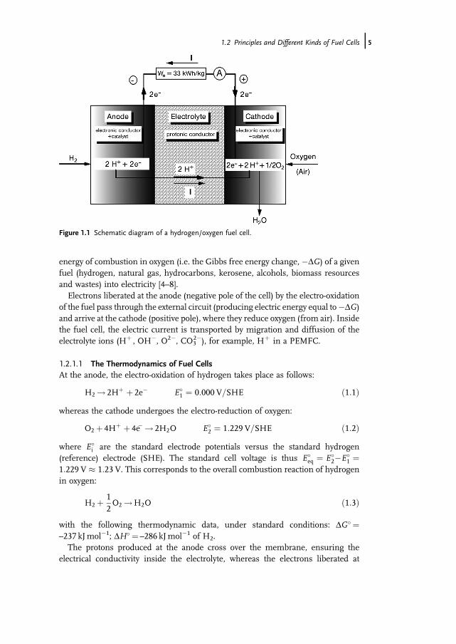
energy of combustion in oxygen (i.e. the Gibbs free energy change, �DG) of a givenfuel (hydrogen, natural gas, hydrocarbons, kerosene, alcohols, biomass resourcesand wastes) into electricity [4–8].Electrons liberated at the anode (negative pole of the cell) by the electro-oxidation
of the fuel pass through the external circuit (producing electric energy equal to�DG)and arrive at the cathode (positive pole), where they reduce oxygen (from air). Insidethe fuel cell, the electric current is transported by migration and diffusion of theelectrolyte ions (Hþ , OH�, O2�, CO3
2�), for example, Hþ in a PEMFC.
1.2.1.1 The Thermodynamics of Fuel CellsAt the anode, the electro-oxidation of hydrogen takes place as follows:
H2 ! 2Hþ þ 2e� E�1 ¼ 0:000 V=SHE ð1:1Þ
whereas the cathode undergoes the electro-reduction of oxygen:
O2 þ 4Hþ þ 4e� ! 2H2O E�2 ¼ 1:229 V=SHE ð1:2Þ
where E�i are the standard electrode potentials versus the standard hydrogen
(reference) electrode (SHE). The standard cell voltage is thus E�eq ¼ E�
2�E�1 ¼
1:229 V � 1:23 V. This corresponds to the overall combustion reaction of hydrogenin oxygen:
H2 þ 12O2 !H2O ð1:3Þ
with the following thermodynamic data, under standard conditions: DG� ¼–237 kJmol�1; DH� ¼ –286 kJmol�1 of H2.The protons produced at the anode cross over the membrane, ensuring the
electrical conductivity inside the electrolyte, whereas the electrons liberated at
Figure 1.1 Schematic diagram of a hydrogen/oxygen fuel cell.
1.2 Principles and Different Kinds of Fuel Cells j5

the anode reach the cathode (where they reduce oxygen) through the external circuit.This process produces an electric energy, Wel¼ nFEeq� ¼ –DG�, correspondingto an energy mass density of the fuel We¼�DG�/(3600M)¼ 32.9 kWhkg�1�33 kWhkg�1, whereM¼ 0.002 kg is themolecular weight of hydrogen, F¼ 96 485Cthe Faraday constant (i.e. the absolute value of the electric charge of 1 mol ofelectrons) and n¼ 2 the number of electrons involved in the oxidation of onehydrogen molecule.The standard electromotive force (emf), E�
eq, at equilibrium (no current flowing)under standard conditions is then calculated as follows:
E�eq ¼ �DG�
nF¼ 237� 103
2� 96485¼ E�
2�E�1 ¼ 1:229 V � 1:23 V ð1:4Þ
The working of the cell under reversible thermodynamic conditions does not followCarnot�s theorem, so that the theoretical energy efficiency, erevcell, defined as the ratiobetween the electrical energy produced (�DG�) and the heat of combustion (�DH�)at constant pressure, is
erevcell ¼We
�DH� ¼nFE�
eq
�DH� ¼DG�
DH� ¼ 1�TDS�
DH� ¼ 237286
¼ 0:83 ð1:5Þ
for the hydrogen/oxygen fuel cell at 25 �C.This theoretical efficiency is much greater (by a factor of about 2) than that of
a thermal combustion engine, producing the reversible work, Wr, according toCarnot�s theorem:
erevtherm ¼ Wr
�DH� ¼Q1�Q2
Q1¼ 1�Q2
Q1¼ 1�T2
T1¼ 0:43 ð1:6Þ
for, for example,T1¼ 350 �CandT2¼ 80 �C,whereQ1 andQ2 are the heat exchangedwith the hot source and cold source, respectively.
1.2.1.2 The Kinetics of Fuel CellsHowever, under working conditions, with a current density j, the cell voltage E( j)becomes smaller than the equilibrium cell voltage Eeq, as the result of three limitingfactors: (i) the overvoltages ha and hc at both electrodes due to a rather low reactionrate of the electrochemical reactions involved (h is defined as the difference betweenthe working electrode potential Ei and the equilibrium potential Eeq
i , so thatEi ¼ Eeq
i þh), (ii) the ohmic dropRej both in the electrolyte and interface resistancesRe and (iii) mass transfer limitations for reactants and products (Figure 1.2) .The cell voltage, E( j), defined as the difference between the cathode potential E2
and the anode potential E1, can thus be expressed as
E j jjð Þ ¼ E2 j jjð Þ�E1 j jjð Þ ¼ Eeq2 þhc� Eeq
1 þha
� ��Rej jj¼ Eeq� jhaj þ jhcj þRej jjð Þ ð1:7Þ
where the overvoltagesha (anodic reaction, i.e. oxidation of the fuelwithha> 0) andhc
(cathodic reaction, i.e. reduction of the oxidant with hc < 0) take into account both the
6j 1 The Direct Ethanol Fuel Cell: a Challenge to Convert Bioethanol Cleanly into Electric Energy

low kinetics of the electrochemical reactions involved (charge transfer overvoltageor activation polarization) and the limiting rate of mass transfer (mass transferovervoltage or concentration polarization) – see Figure 1.3.In the E( j) characteristics one may distinguish three zones associated with these
energy losses:
. Zone I: the Evs j linear curve corresponds to ohmic lossesRej jj in the electrolyte andinterface resistances; a decrease of the specific electric resistance Re from 0.3 to0.15W cm2 gives an increase in the current density j (at 0.7 V) from 0.25 to0.4 Acm�2, that is, an increase in the energy efficiency and in the power densityof 1.6-fold.
. Zone II: the E vs ln(| j|/j0) logarithmic curve corresponds to the charge transferpolarization, that is, to the activation overvoltages due to a relatively low electronexchange rate at the electrode–electrolyte interface, particularly for the oxygenreduction reaction whose exchange current density j0 is much smaller than thatof the hydrogen oxidation; an increase in j0 from 10�8 to 10�6 A cm�2 leads to anincrease in the current density j (at 0.7 V) from0.4 to 0.9 Acm�2, that is, an increasein the energy efficiency and in the power density of 3.6-fold compared with theinitial data.
. Zone III: the E vs ln(1� | j/jl|) logarithmic curve corresponds to concentrationpolarization, which results from the limiting value jl of the mass transfer limitingcurrent density for the reactive species and reaction products to and/or from theelectrode active sites; an increase in jl from 1.4 to 2.2 Acm�2 leads to a further
Figure 1.2 Comparative current density ( j) vs potential (E) curvesfor H2 and EtOH electro-oxidation at different Pt-based catalyticanodes and oxygen electro-reduction at a Pt cathode.
1.2 Principles and Different Kinds of Fuel Cells j7

increase in the current density j (at 0.7 V) from0.9 to 1.5 Acm�2, that is, an increasein the energy efficiency and in the power density of 6-fold comparedwith the initialcurve.
Hence these three key points will determine the energy efficiency and the specificpower of the elementary fuel cell: an improvement in each component of the cell willincrease the power density from 0.175 to 1.05Wcm�2, that is, an increase by a factorof 6. As a consequence, for the fuel cell systems the weight and volume will bedecreased by a similar factor, for a given power of the system, and presumablythe overall cost will be diminished. The improvement in the components of theelementary fuel cell thus has a direct effect on the system technology and therefore onthe overall cost.For a PEMFC, fed with reformate hydrogen and air, the working cell voltage is
typically 0.8 V at 500mAcm�2, which leads to a voltage efficiency eE given by
eE ¼ Eð jÞE�eq
¼ 1� jhað jÞj þ jhcð jÞj þRej jjE�eq
¼ 0:81:23
¼ 0:65 ð1:8Þ
The overall energy efficiency (ecell) thus becomes
ecell ¼ Wel
�DH� ¼nexpFEðj jjÞ�DH� ¼ nexp
nth
Eðj jjÞE�eq
nthFE�eq
�DH� ¼ eFeEerevcell ð1:9Þ
where the faradaic efficiency eF¼nexp/nth is the ratio between the number ofelectrons nexp effectively exchanged in the overall reaction and the theoretical
Figure 1.3 Theoretical E( j) electric characteristics of an H2/O2
fuel cell: (&) j0¼ 10�8 A cm�2, Re¼ 0.30W cm2, jl¼ 1.2 A cm�2;(^) j0¼ 10�8,Re¼ 0.15, jl¼ 1.3; (~) j0¼ 10�6,Re¼ 0.15, jl¼ 1.4;(þ ) j0¼ 10�6, Re¼ 0.10, jl¼ 2.2.
8j 1 The Direct Ethanol Fuel Cell: a Challenge to Convert Bioethanol Cleanly into Electric Energy

numbers of electrons nth for complete oxidation of the fuel (to H2O and CO2). eF¼ 1for hydrogen oxidation, but eF¼ 4/12¼ 0.33 for ethanol oxidation stopping at theacetic acid stage (four electrons exchanged instead of 12 electrons for completeoxidation to CO2) – see Section 1.3.2.1.As an example, the overall energy efficiency of anH2/O2 fuel cell, working at 0.8 V
under 500mAcm�2, is
eH2=O2
cell ¼ 1� 0:65� 0:83 ¼ 0:54 ð1:10Þwhereas that of a DEFC working at 0.5 V under 100mAcm�2 (assuming completeoxidation to CO2) would be
eC2H5OH=O2
cell ¼ 1� 0:44� 0:97 ¼ 0:43 since eF ¼ 1;
eE ¼ 0:51:14
¼ 0:44 and erevcell ¼13251366
¼ 0:97ð1:11Þ
withDG� ¼�1325 kJmol�1,Eeq� ¼ (1325� 103)/(12� 96 485)¼ 1.144VandDH� ¼�1366 kJmol�1 of ethanol (see Section 1.3.2.1).These energy efficiencies are better than those of the best thermal engines (diesel
engines), which have energy efficiency of the order of 0.40.Therefore, it appears that the only way to increase significantly the overall energy
efficiency is to increase eE and eF, that is, to decrease the overvoltagesh and the ohmicdrop Rej and to increase the faradaic efficiency for complete oxidation, since erevcell isgiven by the thermodynamics (one can increase it slightly by changing the pressureand temperature operating conditions). For the hydrogen/oxygen fuel cell, usuallyeF� 1, but it can be much lower in the case of incomplete combustion of the fuel(see, e.g., the case of the DEFC in Section 1.3.2.1). The decrease in |h| is directlyrelated to the increase in the rate of the electrochemical reactions occurring at bothelectrodes. This is typically the field of electrocatalysis, where the action of both theelectrode potential and the catalytic electrodematerial will synergistically increase thereaction rate v [9–11].
1.2.1.3 Catalysis of Fuel Cell Reactions
Electrocatalysis and theRate of Electrochemical Reactions For a given electrochemicalreaction A þ ne�>B, which involves the transfer of n electrons at the electrode/electrolyte interface, the equilibrium potential, called the electrode potential, is givenby the Nernst law:
EA=Beq ¼ EA=B
0 þ RTnF
lnaAaB
ð1:12Þ
where EA=B0 is the standard electrode potential, as measured versus the standard
hydrogen electrode (SHE), the potential of which is zero at 25 �C by definition, and aiis the activity of reactant i.As soon as the electrode potential takes a value EA/B different from the equilibrium
potential EA=Beq , an electrical current of intensity I passes through the interface, the
magnitude of which depends on the deviation h ¼ EA=B�EA=Beq from the equilibrium
1.2 Principles and Different Kinds of Fuel Cells j9

potential. h, which is called the overvoltage, is positive for an oxidation reaction(anodic reaction B ! A þ ne�) and negative for a reduction reaction (cathodicreaction A þ ne� ! B). The current intensity I is proportional to the rate of reactionv, that is, I¼ nFv. For heterogeneous reaction v is proportional to the surface areaS of the interface, so that the kinetics of electrochemical reactions are better definedby the intrinsic rate vi¼ v/S and the current density j¼ I/S¼ nFvi.The electrical characteristics j(E) can then be obtained by introducing the expo-
nential behavior of the rate constant with the electrochemical activation energy,D_
G^ þ ¼ DGþ
0 �anFE, which comprises two terms: the first (DGþ0 ) is the chemical
activation energy and the second (anFE) is the electrical part of the activation energy.This latter is a fractiona (0�a� 1) of the total electric energy, nFE, coming from theapplied electrode potential E, where a is called the charge transfer coefficient(Figure 1.4). In the theory of absolute reaction rate, one obtains, for a first-orderelectrochemical reaction (the rate of which is proportional to the reactant concentra-tion ci):
j ¼ nFvi ¼ nFkðT ;EÞci ¼ nFk0cie�ðDaG‘ þ
=RTÞ
¼ nFk0cie�ðDGþ
0 =RTÞeðanFE=RTÞ ¼ j0eðanFE=RTÞ ð1:13Þ
This equation contains the two essential activation terms met in electrocatalysis:(i) an exponential function of the electrode potentialE and (ii) an exponential functionof the chemical activation energyDGþ
0 . Bymodifying the nature and structure of theelectrodematerial, onemaydecreaseDGþ
0 , by a given amountK (see Figure 1.4), thusincreasing j0, as the result of the catalytic properties of the electrode. This leads to anincrease of the reaction rate vi, that is, the current density j.
Electrocatalytic Oxidation of Hydrogen The rate constant of the hydrogen oxidationreaction (HOR), as measured by the exchange current density j0 (i.e. the current
Figure 1.4 Activation barrier for an electrochemical reaction. K isthe decrease in activation energy due to the electrode catalyst andanFE is that due to the electrode potential E.
10j 1 The Direct Ethanol Fuel Cell: a Challenge to Convert Bioethanol Cleanly into Electric Energy

density at the equilibrium potential EA=Beq , where the anodic current is exactly
compensated by the cathodic current, so that the overall current is zero) dependsgreatly on the electrode material (Figure 1.5).These values can be correlated with the heat of adsorption of hydrogen on the
catalytic metal since the oxidation mechanism, apart from diffusion and masstransport limitations, is controlled by an adsorption step in a two consecutive stepmechanism:
H2 ! 2Hads dissociative adsorption of hydrogen ð1:14Þ
2ðHads !Hþaq þ e�Þ electron transfer reaction ð1:15Þ
H2 ! 2Hþaq þ 2e� overall oxidation reaction ð1:16Þ
where Hþaq is a proton solvated by the electrolytic medium (usually an aqueous
electrolyte). This leads to a Volcano plot (Figure 1.5) with a maximum of activity forthe transition noble metals (Pt, Pd, Rh).
Oxidation of Alcohols in a Direct Alcohol Fuel Cell The electrocatalytic oxidation ofan alcohol (methanol, ethanol, etc.) in a direct alcohol fuel cell (DAFC) will avoid thepresence of a heavy and bulky reformer, which is particularly convenient forapplications to transportation and portable electronics. However, the reaction mech-anism of alcohol oxidation is much more complicated, involving multi-electrontransfer with many steps and reaction intermediates. As an example, the completeoxidation of methanol to carbon dioxide:
CH3OHþH2O!CO2 þ 6Hþ þ 6e� ð1:17Þ
Figure 1.5 Exchange current density of the hydrogen reaction as afunction of the metal–hydrogen bond energy [12].
1.2 Principles and Different Kinds of Fuel Cells j11

involves the transfer of six electrons and the formation ofmany adsorbed species andreaction intermediates, among them adsorbed CO, which blocks the active sites ofplatinumcatalysts. As a result of such a complex reaction, the oxidation overvoltageha
is relatively high (0.3–0.5 V), so that more effective electrocatalysts are needed inorder to increase the reaction rate and thus to decrease ha. Therefore, several bi- andtrimetallic catalysts were developed, among which Pt/Ru-based electrocatalysts leadto the best performance.Pt/Ru electrocatalysts are currently used in DMFC stacks of a few watts to a few
kilowatts. The atomic ratio between Pt and Ru, the particle size and themetal loadingof carbon-supported anodes play a key role in their electrocatalytic behavior.Commercial electrocatalysts (e.g. from E-Tek) consist of 1 : 1 Pt/Ru catalysts dis-persed on an electron-conducting substrate, for example carbon powder such asVulcan XC72 (specific surface area of 200–250m2 g�1). However, fundamentalstudies carried out in our laboratory [13] showed that a 4 : 1 Pt/Ru ratio gives highercurrent and power densities (Figure 1.6).This may be explained by the bifunctional theory of electrocatalysis developed by
Watanabe and Motoo [14], according to which Pt activates the dissociative chemi-sorption of methanol to CO, whereas Ru activates and dissociates water molecules,leading to adsorbed hydroxyl species, OH. A surface oxidation reaction betweenadsorbed CO and adsorbed OH becomes the rate-determining step. The reactionmechanism can be written as follows [15]:
PtþCH3OH!Pt�CH3OHads ð1:18Þ
Pt�CH3OHads !Pt�CHOads þ 3Hþ þ 3e� ð1:19Þ
Pt�CHOads !Pt�COads þHþ þ e� ð1:20Þ
RuþH2O!Ru�OHads þHþ þ e� ð1:21Þ
Figure 1.6 (a) E( j) and (b) P( j ) curves at 110 �C of a DMFCwithdifferent Pt/Ru atomic ratios in the anode catalyst (&, 50 : 50;~,70 : 30; ^, 80 : 20).
12j 1 The Direct Ethanol Fuel Cell: a Challenge to Convert Bioethanol Cleanly into Electric Energy

Pt�COads þRu�OHads !PtþRuþCO2 þHþ þ e� ð1:22Þ
Overall reaction:
CH3OHþH2O!CO2 þ 6Hþ þ 6e� ð1:23ÞIn this reaction mechanism, three or four Pt sites are involved in methanol
dissociation, whereas only one Ru site is involved in water activation, so that the bestPt/Ru atomic ratio is between 3 : 1 and 4 : 1 [15].Some Pt/Ru-based trimetallic electrocatalysts, such as Pt/Ru/Mo, give enhanced
catalytic activity leading to a power density, in an elementary single DMFC, at leasttwice that of Pt/Ru catalyst.
Electrocatalytic Reduction of Dioxygen The electrocatalytic reduction of oxygen isanother multi-electron transfer reaction (four electrons are involved) with severalsteps and intermediate species [16]. A four-electron mechanism, leading to water,is in competition with a two-electron mechanism, giving hydrogen peroxide. Thefour-electron mechanism on a Pt electrode can be written as follows:
PtþO2 !Pt�O2ads ð1:24Þ
Pt�O2ads þHþ þ e� !Pt�O2Hads ð1:25Þ
PtþPt�O2Hads ! Pt�Oads þPt�OHads ð1:26Þ
Pt�Oads þHþ þ e� !Pt�OHads ð1:27Þ
2Pt�OHads þ 2Hþ þ 2e� ! 2Ptþ 2H2O ð1:28Þ
Overall reaction:
O2 þ 4Hþ þ 4e� ! 2H2O ð1:29ÞThis complex reduction reaction leads to a relatively high overvoltage – at least
0.3 V – thus decreasing the cell voltage of the fuel cell by the same quantity. Pt–Xbinary catalysts (with X¼Cr, Ni, Fe, . . .) give some improvements in the electro-catalytic properties compared with pure Pt dispersed on Vulcan XC72 [17].In addition, in a DAFC, the proton exchange membrane is not completely alcohol
tight, so that some alcohol leakage to the cathodic compartment will lead to a mixedpotential with the oxygen electrode. Thismixed potential will decrease further the cellvoltage by about 0.1–0.2 V. It turns out that new electrocatalysts insensitive to thepresence of alcohols are needed for the DAFC.Transition metal compounds, such as organic macrocycles, are known to be good
electrocatalysts for oxygen reduction. Furthermore, they are inactive for alcoholoxidation. Different phthalocyanines and porphyrins of iron and cobalt were thusdispersed in an electron-conducting polymer (polyaniline, polypyrrole) acting asa conductingmatrix, either in the formof a tetrasulfonated counter anion or linked to
1.2 Principles and Different Kinds of Fuel Cells j13
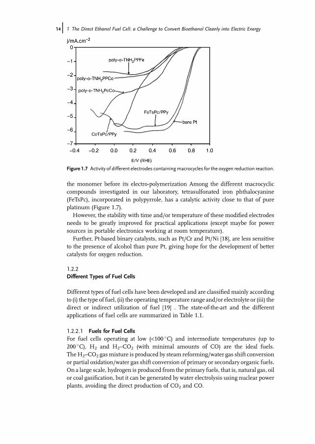
the monomer before its electro-polymerization Among the different macrocycliccompounds investigated in our laboratory, tetrasulfonated iron phthalocyanine(FeTsPc), incorporated in polypyrrole, has a catalytic activity close to that of pureplatinum (Figure 1.7).However, the stability with time and/or temperature of these modified electrodes
needs to be greatly improved for practical applications (except maybe for powersources in portable electronics working at room temperature).Further, Pt-based binary catalysts, such as Pt/Cr and Pt/Ni [18], are less sensitive
to the presence of alcohol than pure Pt, giving hope for the development of bettercatalysts for oxygen reduction.
1.2.2Different Types of Fuel Cells
Different types of fuel cells have been developed and are classified mainly accordingto (i) the type of fuel, (ii) the operating temperature range and/or electrolyte or (iii) thedirect or indirect utilization of fuel [19] . The state-of-the-art and the differentapplications of fuel cells are summarized in Table 1.1.
1.2.2.1 Fuels for Fuel CellsFor fuel cells operating at low (<100 �C) and intermediate temperatures (up to200 �C), H2 and H2–CO2 (with minimal amounts of CO) are the ideal fuels.TheH2–CO2 gasmixture is produced by steam reforming/water gas shift conversionor partial oxidation/water gas shift conversion of primary or secondary organic fuels.On a large scale, hydrogen is produced from the primary fuels, that is, natural gas, oilor coal gasification, but it can be generated by water electrolysis using nuclear powerplants, avoiding the direct production of CO2 and CO.
Figure 1.7 Activity of different electrodes containingmacrocycles for the oxygen reduction reaction.
14j 1 The Direct Ethanol Fuel Cell: a Challenge to Convert Bioethanol Cleanly into Electric Energy

Table1.1Status
offuelcelltechno
logies.
Type
offuelcella;o
peratin
gfuel
andtemperature
Power
ratin
g(kW)
Fuel
efficiency(%
)Po
wer
density
(mW
cm�2 )
Lifetim
e(h)
Capita
lcost
($kW
�1 )
App
lications
SOFC;C
H4,coal?,8
00–10
00� C
25–50
0050–60
200–40
080
00–40
000
1500
Base-load
andInterm
ediate
load,p
ower
generation,co-generation
MCFC;C
H4,coal?,6
50� C
100–50
0050–55
150–30
010
000–40
000
1250
Base-load
andinterm
ediate
load,p
ower
generation–co-gen
eration
PAFC;C
H4,C
H3OH,o
il,20
0� C
200–10
000
40–45
200–30
030
000–40
000
200–3000
On-siteintegrated
energy
system
s,tran
sportation
(fleetvehicles),load-levelin
gAFC;H
2,8
0� C
20–10
065
250–40
030
00–10
000
1000
Spaceflights,space
stations,tran
sportation
,APU
PEMFC;H
2,C
H3OH,2
5–10
0� C
0.01–25
040–50
500–10
0010
000–10
000
050–2000
Tran
sportation
,stand-by
power,p
ortablepo
wer,
spacestations
DMFC;C
H3O
H,2
5–15
0� C
0.001–10
30–45
50–20
010
00–10
000
1000
Portablepo
wer,stand-by
power,transportation
(?),
APU
SAMFC;H
2,C
H3OH,C
2H
5OH,
NaB
H4,2
5–80
� C0.001–0.1
30–60
10–10
0?
?Portablepo
wer
aSO
FC¼solid
oxidefuelcell;MCFC¼moltencarbon
atefuelcell;PAFC¼ph
osph
oricacidfuelcell;AFC¼alkalin
efuelcell;PEMFC¼proton
exchan
gemem
bran
efuelcell;
DMFC¼direct
methan
olfuel
cell;
SAMFC¼So
lidalkalin
emem
bran
efuel
cell.
1.2 Principles and Different Kinds of Fuel Cells j15

These fuels (pure H2, H2–CO2, H2–CO–CO2) may also be produced from renew-able energy sources, such as biomass, solar, windmill and hydroelectric power.Hydrogen is a secondary fuel and, like electricity, is an energy carrier. It is themost
electroactive fuel for fuel cells operating at low and intermediate temperatures.Methanol and ethanol are the most electroactive alcohol fuels, and, when they areelectro-oxidized directly at the fuel cell anode (instead of being transformed in ahydrogen-rich gas in a fuel processor), the fuel cell is called a DAFC: either a DMFC(with methanol) or a DEFC (with ethanol).
1.2.2.2 Hydrogen-fed Fuel CellsHydrogen/oxygen (air) fuel cells are classified according to the type of electrolyte usedand the working temperature:
. Solid oxide fuel cell (SOFC) working between 700 and 1000 �C with a solid oxideelectrolyte, such as yttria-stabilized zirconia (ZrO2–8% Y2O3), conducting by theO2� anion.
. Molten carbonate fuel cell (MCFC) working at about 650 �C with a mixture ofmolten carbonates (Li2CO3–K2CO3) as electrolyte, conducting by the CO3
2� anion.
Both of the above are high-temperature fuel cells.
. Phosphoric acid fuel cell (PAFC) working at 180–200 �C with a porous matrix ofPTFE-bonded silicon carbide impregnated with phosphoric acid as electrolyte,conducting by the Hþ cation. This medium-temperature fuel cell is now commer-cialized by ONSI (USA), mainly for stationary applications.
. Alkaline fuel cell (AFC) working at 80 �C with concentrated potassium hydroxideas electrolyte, conducting by the OH� anion. This kind of fuel cell, developed byIFC (USA), is now used in space shuttles.
. Proton exchange membrane fuel cell (PEMFC) working at around 70 �C with apolymer membrane electrolyte, such as Nafion, which is a solid proton conductor(conducting by the Hþ cation).
. Direct methanol fuel cell (DMFC) working between 30 and 110 �C with a protonexchange membrane (such as Nafion) as electrolyte, which realizes the directoxidation of methanol at the anode.
. Solid alkaline membrane fuel cell (SAMFC) working at moderate temperatures(20–80 �C) for which an anion-exchange membrane (AEM) is the electrolyte,electrically conducting by, for example, hydroxyl ions (OH�).
1.2.2.3 Methanol- and Ethanol-fed Fuel CellsIn addition to hydrogen as a fuel, methanol or ethanol can be directly converted intoelectricity in a DAFC, the great progress of which resulted from the use of a protonexchangemembrane acting both as an electrolyte (instead of the aqueous electrolytespreviously used) and as a separator preventing the mixing of fuel and oxidant.ADAFCcanwork atmoderate temperatures (30–50 �C) for portable applications, butnow the tendency is to look for newmembranes that are less permeable to alcohol and
16j 1 The Direct Ethanol Fuel Cell: a Challenge to Convert Bioethanol Cleanly into Electric Energy

work at higher temperatures (80–120 �C) to increase the rate of the electrochemicalreactions involved (oxidation of alcohol and reduction of oxygen) and to managebetter the heat produced, either to use it in a co-generation system or to evacuate it intransportation applications.The last three fuel cells (PEMFC, DAFC and SAMFC) are low-temperature fuel
cells. In this chapter, the discussionwill be focused on these fuel cells, particularly thePEMFC and the DAFC, since they can accommodate biomass fuels, either after fuelprocessing to obtain reformate hydrogen or directly with bioethanol.For these low-temperature fuel cells, the development of catalytic materials is
essential to activate the electrochemical reactions involved. This concerns theelectro-oxidation of the fuel (reformate hydrogen containing some traces of CO,which acts as a poisoning species for the anode catalyst; methanol and ethanol,which have a relatively low reactivity at low temperatures) and the electro-reduction of the oxidant (oxygen), which is still a source of high energy losses(up to 30–40%) due to the low reactivity of oxygen at the best platinum-basedelectrocatalysts.
1.3Low-temperature Fuel Cells (PEMFCs and DAFCs)
1.3.1Proton Exchange Membrane Fuel Cell (PEMFC)
The PEMFC is nowadays the most advanced low-temperature fuel cell technology[19, 20], because it can be used in several applications (space programs, electricvehicles, stationary power plants, auxiliary power units, portable electronics).The progress made in one application is greatly beneficial to the others.
1.3.1.1 Principle of a PEMFCAn elementary PEMFC consists of a thin film (10–200mm) of a solid polymerelectrolyte (a protonic membrane, such as Nafion), on both sides of which theelectrode structures (fuel anode and oxygen cathode) are pasted, giving a membra-ne–electrode assembly (MEA) (Figure 1.8). A single cell delivers a cell voltage of0.5–0.9 V (instead of the theoretical emf of 1.23 V under standard equilibriumconditions), depending on the working current density. Many elementary cells,electrically connected by bipolar plates, are assembled together (in series and/or inparallel) to reach the nominal voltage (such as 48V for electric vehicles) and thenominal power of the fuel cell stack.In PEMFCs working at low temperatures (20–90 �C), several problems need to be
solved before the technological development of fuel cell stacks for different applica-tions. This concerns the properties of the components of the elementary cell, that is,the proton exchange membrane, the electrode (anode and cathode) catalysts, themembrane–electrode assemblies and the bipolar plates [19, 20]. This also concernsthe overall system with its control and management equipment (circulation ofreactants and water, heat exhaust, membrane humidification, etc.).
1.3 Low-temperature Fuel Cells (PEMFCs and DAFCs) j17
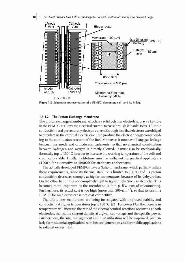
1.3.1.2 The Proton Exchange MembraneThe proton exchangemembrane, which is a solid polymer electrolyte, plays a key rolein the PEMFC. It allows the electrical current to pass through it thanks to itsHþ ionicconductivity and prevents any electron current through it so that electrons are obligedto circulate in the external electric circuit to produce the electric energy correspond-ing to the combustion reaction of the fuel. Moreover, it must avoid any gas leakagebetween the anode and cathode compartments, so that no chemical combinationbetween hydrogen and oxygen is directly allowed. It must also be mechanically,thermally (up to 150 �C in order to increase the working temperature of the cell) andchemically stable. Finally, its lifetime must be sufficient for practical applications(4 000 h for automotive to 40 000 h for stationary applications).The actually developed PEMFCs have a Nafion membrane, which partially fulfills
these requirements, since its thermal stability is limited to 100 �C and its protonconductivity decreases strongly at higher temperatures because of its dehydration.On the other hand, it is not completely tight to liquid fuels (such as alcohols). Thisbecomes more important as the membrane is thin (a few tens of micrometers).Furthermore, its actual cost is too high (more than 500D m�2), so that its use in aPEMFC for an electric car is not cost competitive.Therefore, new membranes are being investigated with improved stability and
conductivity at higher temperatures (up to 150 �C) [21]. For power FCs, the increase intemperature will increase the rate of the electrochemical reactions occurring at bothelectrodes, that is, the current density at a given cell voltage and the specific power.Furthermore, thermal management and heat utilization will be improved, particu-larly for residential applications with heat co-generation and for mobile applicationsto exhaust excess heat.
Figure 1.8 Schematic representation of a PEMFC elementary cell (and its MEA).
18j 1 The Direct Ethanol Fuel Cell: a Challenge to Convert Bioethanol Cleanly into Electric Energy

1.3.1.3 The Electrode CatalystsOne of the main problems with low-temperature (20–80 �C) PEMFCs is the relativelyslowkinetics of the electrochemical reactions involved, such as oxygen reduction at thecathode and fuel (hydrogen from a reformate gas or alcohols) oxidation at the anode.The reaction rates can only be increased by the simultaneous action of the electrodepotential and electrode material (electrocatalytic activation). Moreover, increasing theworking temperature from 80 to 150 �Cwould strongly increase (by a factor of at least100–1000) the rates of the electrochemical reactions (thermal activation). All thesecombined effects would increase the cell voltage by about 0.1–0.2V, since at roomtemperature the anode and cathode overvoltages are close to 0.2–0.4V, whichdecreases the cell voltage by 0.4–0.7 V, leading to values close to 0.5–0.7V insteadof the theoretical cell voltage of 1.23V.The investigation of new electrocatalysts, particularly Pt-based catalysts, that are
more active for oxygen reduction and fuel oxidation (hydrogen from reformate gas oralcohols) is thus an important point for the development of PEMFCs [16, 17, 22, 23].
1.3.1.4 The Membrane–Electrode AssemblyThe realization of the MEA is a crucial point for constructing a good fuel cell stack.The method currently used consists in hot-pressing (at 130 �C and 35 kg cm�2) theelectrode structures on the polymer membrane (Nafion). This gives non-repro-ducible results (in terms of interface resistance) and this is difficult to industrial-ize. New concepts must be elaborated, such as the continuous assembly ofthe three elements in a rolling tape process (as in the magnetic tape industry)or successive deposition of the component layers (microelectronic process) andso on.
1.3.1.5 The Bipolar PlatesThe bipolar plates, which separate both electrodes of neighboring cells (one anode ofa cell and one cathode of the other), have a triple role:
. to ensure the electron conductivity between two neighboring cells;
. to allow the distribution of reactants (gases and liquids in the case of alcohols) to theelectrode catalytic sites and to evacuate the reaction products (H2O and CO2 in thecase of alcohols);
. thermal management inside the elementary cell by evacuating the excess heat.
The bipolar plates are usually fabricated with non-porous machined graphite orcorrosion-resistant metal plates. Distribution channels are engraved in these plates.Metallic foams can also be used for distributing the reactants. One key point is toensure a low ohmic resistance inside the bipolar plate and at the contact with theMEA.Another point is to usematerialswith high corrosion resistance in the oxidativeenvironment of the oxygen cathode.
1.3.1.6 Auxiliary and Control EquipmentA more detailed picture of a PEMFC system, including the auxiliary and controlequipments, is shown in Figure 1.9.
1.3 Low-temperature Fuel Cells (PEMFCs and DAFCs) j19

Fuel supply is usually from liquid hydrogen or pressurized gaseous hydrogen.For other fuels, a fuel processor is needed, which includes a reformer, water gas shiftreactors and purification reactors, in order to decrease the amount of CO to anacceptable level (below a few tens of ppm), which would otherwise poisonthe platinum-based catalysts. This equipment is still heavy and bulky and limitsthe dynamic response of the fuel cell stack, particularly for the electric vehicle in someurban driving cycles.On the other hand, the other auxiliary equipment depends greatly on the stack
characteristics:
. air compressor, the characteristics of which are related to the pressures supportedby the proton exchange membrane;
. humidifiers for the reacting gases with controlled humidification conditions;
. preheating of gases to avoid condensation phenomena;
. hydrogen recirculation and purging systems of the anode compartment;
. cooling system for the MEAs;
. control of pressure valves and/or of gas flows;
. DC/DC or DC/AC electric converters.
The system control must ensure correct working of the system, not only understeady-state conditions, but also during power transients. All the elementary cellsmust be controlled (the cell voltage of each elementary cell, if possible) and thepurging system must be activated in the case of a technical hitch.According to different applications (stationary power plants, power sources for
electric vehicle, auxiliary power units, etc.), different specifications and systemdesign are required.
Figure 1.9 Detailed scheme of a PEMFC system with its auxiliary and control equipments.
20j 1 The Direct Ethanol Fuel Cell: a Challenge to Convert Bioethanol Cleanly into Electric Energy

1.3.2Direct Ethanol Fuel Cell (DEFC)
1.3.2.1 Principle of the Direct Ethanol Fuel CellA schematic diagram of a DEFC is shown in Figure 1.10.The DEFC transforms directly the Gibbs energy of combustion of ethanol into
electricity, without a fuel processor. This greatly simplifies the system, reducing itsvolume and cost [22, 23]. The important development of DEFCs is due to the use ofa proton exchange membrane as electrolyte, instead of a liquid acid electrolyte,as done previously.At the anode, the electro-oxidation of ethanol takes place as follows, leading, in the
case of complete oxidation, to CO2:
CH3CH2OHþ 3H2O! 2CO2 þ 12Hþ þ 12e� E�1 ¼ 0:085 V vs SHE
ð1:30Þwhereas the electro-reduction of oxygen occurs at the cathode:
O2 þ 4Hþ þ 4e� ! 2H2O E�2 ¼ 1:229 V vs SHE
ð1:31Þwhere E�
i are the electrode potentials versus SHE. This corresponds to the overallcombustion reaction of ethanol into oxygen:
CH3CH2OH þ 3O2 ! 2CO2 þ 3H2O ð1:32Þwith the thermodynamic data, under standard conditions:
DG� ¼ �1325 kJ mol�1; DH� ¼ �1366 kJ mol�1 of ethanol ð1:33ÞThis gives a standard emf at equilibrium:
E�eq ¼ �DG�
nF¼ 1325� 103
12� 96485¼ E�
2�E�1 ¼ 1:144 V ð1:34Þ
Figure 1.10 Schematic diagram of a DEFC.
1.3 Low-temperature Fuel Cells (PEMFCs and DAFCs) j21

with n¼ 12 the number of electrons exchanged per molecule for complete oxidationto CO2. The corresponding electrical energy,Wel ¼ nFE�
eq ¼ �DG�, leads to a massenergy density We¼�DG�/(3600M)¼ 8 kWhkg�1, where M¼ 0.046 kg is themolecular weight of ethanol.The theoretical energy efficiency, under reversible standard conditions, defined as
the ratio between the electrical energy produced (�DG�) and the heat of combustion(�DH�) at constant pressure, is – see Equation 1.5
erevcell ¼DG�
DH� ¼13251366
¼ 0:97 ð1:35Þ
However, under working conditions, with a current density j, the cell voltage E( j) islower than Eeq – see Equation 1.7 – so that the practical energy efficiency, for a DEFCworking at 0.5 V and 100mAcm�2 with complete oxidation to CO2, would be – seeEquation 1.9
eC2H5OH=O2
cell ¼ eF � eE � erevcell ¼ 1� 0:437� 0:97 ¼ 0:424 ð1:36Þ
since the potential efficiency eE¼E( j)/Eeq¼ 0.5/1.14¼ 0.437 and the faradaic effi-ciency eF¼nexp/nth¼ 1 for complete oxidation to CO2. This is similar to that of thebest thermal engine (diesel engine). However, if the reaction process stops at theacetic acid stage, which involves the transfer of four electrons (instead of 12 forcomplete oxidation), the efficiency will be reduced by two-thirds, reaching only 0.15.An additional problem arises from ethanol crossover through the proton exchange
membrane. It results that the platinum cathode experiences a mixed potential, sinceboth the oxygen reduction and ethanol oxidation take place at the same electrode.The cathode potential is therefore lower, leading to a decrease in the cell voltage anda further decrease in the voltage efficiency.
1.3.2.2 Reaction Mechanisms of Ethanol OxidationThe electrochemical oxidation of ethanol has been extensively studied at platinumelectrodes [22–34]. Thefirst step is the dissociative adsorption of ethanol, either via anO-adsorption or a C-adsorption process [25, 26], to form acetaldehyde (AAL)according to the following reaction equations. Indeed, it was shown by Hitmiet al. [34] that AAL was formed at potentials lower than 0.6 V vs RHE. Thus:
PtþCH3CH2OH!Pt�ðOCH2CH3Þads þHþ þ e� ð1:37Þor
PtþCH3CH2OH!Pt�ðCHOHCH3Þads þHþ þ e� ð1:38Þfollowed (at E < 0.6 V vs RHE) by
Pt�ðOCH2CH3Þads !PtþCHOCH3 þHþ þ e� ð1:39Þor
Pt�ðCHOHCH3Þads !PtþCHOCH3 þHþ þ e� ð1:40Þ
22j 1 The Direct Ethanol Fuel Cell: a Challenge to Convert Bioethanol Cleanly into Electric Energy

AAL has to be readsorbed to oxidize further either into acetic acid or carbon dioxide.To complete the oxidation reaction leading to both of these species, an extra oxygenatom is needed, which has to be brought by activated (adsorbed) water moleculesat the platinum surface.Thus, as soon as AAL is formed, it can adsorb on platinum sites leading. to a
Pt–COCH3 species at E < 0.6 V vs RHE:
PtþCHOCH3 !Pt�ðCOCH3Þads þHþ þ e� ð1:41Þ
Further oxidation, without breaking of the –C–C– bond, may occur at potentials>0.6 V vs RHE, through the activation of water molecules at platinum sites:
PtþH2O!Pt�ðOHÞads þHþ þ e� at E > 0:6 V vs RHE ð1:42Þ
Pt�ðCOCH3Þads þPt�ðOHÞads ! 2PtþCH3COOH ð1:43Þ
On the other hand, SNIFTIRS measurements have clearly shown that Pt is able tobreak the –C–C– bond, leading to adsorbed CO species at relatively low anodepotentials (from 0.3V vs RHE) [35]. However, Iwasita and Pastor [26] found sometraces of CH4 at potentials lower than 0.4 V vs RHE. Thus:
Pt�ðCOCH3Þads þPt!Pt�ðCOÞads þPt�ðCH3Þads at E > 0:3 V vs RHE
ð1:44Þ
and
Pt�ðCH3Þads þPt�ðHÞads ! 2PtþCH4 at E < 0:4 V vs RHE
ð1:45Þ
At potentials higher than 0.6 V vs RHE, the dissociative adsorption of water occurs onplatinum, providing –OH adsorbed species, able to oxidize further the adsorptionresidues of ethanol. Then, oxidation of adsorbed CO species occurs as was shown byFTIR reflectance spectroscopy and CO stripping experiments [36]:
Pt�ðCOÞads þPt�ðOHÞads ! 2PtþCO2 þHþ þ e� ð1:46ÞAAL can also be oxidized, leading to acetic acid (AA), as follows:
Pt�ðCHOCH3Þads þPt�ðOHÞads ! 2PtþCH3COOHþHþ þ e� ð1:47Þ
In a recent study, the analysis of the reaction products at the outlet of the anodecompartment of a DEFC fitted with a Pt/C anode showed that only AA, AAL and CO2
could be detected byHPLC [24]. Depending on the electrode potential, AAL, AA, CO2
and traces of CH4 are observed, the main products being AAL and AA (Table 1.2),AA being considered as a final product because it is not oxidized under smoothconditions. Long-term electrolysis experiments on a Pt catalyst show that AAL isdetected at potentials as low as 0.35V vs RHE, whereas no AA was detected in thispotential range.
1.3 Low-temperature Fuel Cells (PEMFCs and DAFCs) j23
From the results given in Table 1.2, it appears that the addition of tin to platinumgreatly favors the formation of AA compared with AAL, as explained by thebifunctional mechanism [14].Several added metals were investigated to improve the kinetics of ethanol
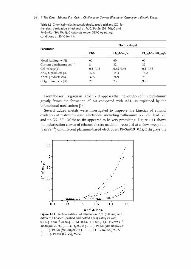
oxidation at platinum-based electrodes, including ruthenium [27, 28], lead [29]and tin [22, 30]. Of these, tin appeared to be very promising. Figure 1.11 showsthe polarization curves of ethanol electro-oxidation recorded at a slow sweep rate(5mVs�1) on different platinum-based electrodes. Pt–Sn(0.9 : 0.1)/C displays the
Figure 1.11 Electro-oxidation of ethanol on Pt/C (full line) anddifferent Pt-based (dashed and dotted lines) catalysts with0.1mgPt cm�2 loading. 0.1M HClO4 þ 1M C2H5OH; 5mV s�1;3000 rpm; 20 �C. (——), Pt/XC72; (- - - - - -), Pt–Sn (90 : 10)/XC72;(���������), Pt–Sn (80 : 20)/XC72; (�-�-�-�-�-), Pt–Ru (80 : 20)/XC72;(-��-��-��-), Pt-Mo (80 : 20)/XC72.
Table 1.2 Chemical yields in acetaldehyde, acetic acid and CO2 forthe electro-oxidation of ethanol at Pt/C, Pt–Sn (90 : 10)/C andPt–Sn-Ru (86 : 10 : 4)/C catalysts under DEFC operatingconditions at 80 �C for 4 h.
ParameterElectrocatalyst
Pt/C Pt0.9Sn0.1/C Pt0.86Sn0.1Ru0.04/C
Metal loading (wt%) 60 60 60Current density(mAcm�2) 8 32 32Cell voltage(V) 0.3–0.35 0.45–0.49 0.5–0.55AAL/S products (%) 47.5 15.4 15.2AA/S products (%) 32.5 76.9 75CO2/S products (%) 20 7.7 9.8
24j 1 The Direct Ethanol Fuel Cell: a Challenge to Convert Bioethanol Cleanly into Electric Energy

best activity in the potential range 0.15–0.5 V vs RHE, as it gives a higher oxidationcurrent density than the other catalysts. The role of tin can also be established byanalyzing the distribution of reaction products at the anode outlet of a fuel cellfittedwith a Pt–Sn(0.9 : 0.1)/C anode and from in situ IR reflectance spectroscopicmeasurements [24, 37].Table 1.2 indicates that alloying platinum with tin led to important changes in the
product distribution: an increase in the AA chemical yield and a decrease in the AALand CO2 chemical yields. The presence of tin seems to allow, at lower potentials, theactivation of water molecules and the oxidation of AAL species into AA. In the samemanner, the amount ofCO2decreased,which can be explained by theneed for severaladjacent platinum atoms (three or four) to realize the dissociative adsorption ofethanol into CO species, via breaking the C–C bond. In the presence of tin, �dilution�of platinum atoms can limit this reaction. The effect of tin, in addition to theactivation of water molecules, may be related to some electronic effects (ligandeffects) on the CO oxidation reaction [38].On Pt–Sn, assuming that ethanol adsorbs only on platinum sites, the first step can
be the same as for platinum alone. However, as was shown by SNIFTIRS experi-ments [37], the dissociative adsorption of ethanol on a PtSn catalyst to form adsorbedCO species takes place at lower potentials than on a Pt catalyst, between 0.1 and 0.3 Vvs RHE, whereas on a Pt catalyst the dissociative adsorption of ethanol takes placeat potentials between 0.3 and 0.4 V vs RHE. Hence it can be stated that the samereactions occur at lower potentials and with relatively rapid kinetics. Once interme-diate species such as Pt–(COCH3)ads and Pt–(CO)ads are formed, they can be oxidizedat potentials close to 0.3 V vs RHE, as confirmed by CO stripping experiments,because OH species are formed on tin at lower potentials [39, 40]:
SnþH2O! Sn�ðOHÞads þHþ þ e� ð1:48Þthen adsorbed acetyl species can react with adsorbed OH species to produce AAaccording to
Pt�ðCOCH3Þads þSnðOHÞads !PtþSnþCH3COOH ð1:49ÞSimilarly, Pt–(CO)ads species are oxidized as follows:
Pt�ðCOÞads þ Sn�ðOHÞads !PtþSnþCO2 þHþ þ e� ð1:50ÞThis mechanism explains also the higher efficiency of Pt–Sn in forming AA
compared with Pt at low potentials (E < 0.35V vs RHE), as was shown by electrolysisexperiments. Indeed, adsorbed OH species on Sn atoms can be used to oxidizeadsorbed CO species to CO2 or to oxidize adsorbed –COCH3 species to CH3COOH,according to the bifunctional mechanism [14].On the other hand, the yield of CO2 with a Pt/C catalyst is double that with a
Pt–Sn/C catalyst (see Table 1.2). This can be explained by the need to have severaladjacent platinum sites to adsorb dissociatively the ethanolmolecule and to break theC–C bond. As soon as some tin atoms are introduced between platinum atoms, thislatter reaction is disadvantaged.
1.3 Low-temperature Fuel Cells (PEMFCs and DAFCs) j25

The spectro-electrochemical study of the adsorption and oxidation of ethanol andthe HPLC analyses of reaction products underline the necessity to activate watermolecules at lower potentials in order to increase the activity of the catalyst and theselectivity towards eitherAAorCO2 formation, whichmeans the improvement of thepotential eE and faradaic eF efficiencies. To perform this, modification of platinum byanother metal is necessary.
1.3.2.3 DEFC TestsThe preparation of electrodes andMEAs have been described elsewhere [15]. FC tests(determination of the cell voltage E and power density P versus the current density j)were carried out in a single DEFCwith 5 or 25 cm2 geometric surface area electrodesusing a Globe Tech test bench, purchased from ElectroChem (USA) (Figure 1.12).The cell voltage E and current density j were recorded using a high-power
potentiostat (Wenking Model HP 88) interfaced with a variable resistance in orderto fix the current applied to the cell andwith a PC to apply constant current sequencesand to store the data.The reaction products at the outlet of the anode side of the DEFC were analyzed
quantitatively by HPLC, as described previously [24]. Large surface area electrodes(25 cm2) were used in order to have a sufficient amount of products. The currentdensity was kept constant and the voltage of the cell was simultaneouslymeasured asa function of time. The ethanol flow rate was chosen close to 2mLmin�1 in order toperform long-term experiments (for at least 4 h) to obtain enough reaction productssuitable for chemical analysis.
Figure 1.12 Typical configuration of a setup for DEFC studies.
26j 1 The Direct Ethanol Fuel Cell: a Challenge to Convert Bioethanol Cleanly into Electric Energy

The experiments were carried out using Pt/C, Pt–Sn/C and Pt–Sn–Ru/C catalystsand in each case no other reaction products than AAL, AA and CO2 were detected.The addition of tin to platinum not only increases the activity of the catalyst towardsthe oxidation of ethanol and therefore the electrical performance of the DEFC, butalso changes greatly the product distribution: the formation of CO2 and AAL islowered, whereas that of AA is greatly increased (Table 1.2).Typical electrical performances obtained with several Pt-based electrocatalysts are
shown in Figure 1.13. The use of platinum alone as anode catalyst leads to poorelectrical performance, the open circuit voltage (OCV) being lower than 0.5 Vand themaximum current density reaches only 100mAcm�2, leading to a maximum powerdensity lower than 7mWcm�2 at 110 �C. The addition of Ru and especially of Sn toplatinum in the anode catalyst greatly enhances the electrical performance of theDEFCby increasing theOCV to 0.75V,which indicates that themodified catalysts areless poisoned by adsorbed species coming fromethanol chemisorption than the Pt/Ccatalyst. For Pt–Sn (80 : 20), current densities up to 150mAcm�2 are reached at110 �C, giving a maximum power density greater than 25mWcm�2, which meansan electrical performances four times higher than those obtained with Pt/C. Theincrease in the electrical performance indicates that the bimetallic catalyst is moreactive for ethanol electro-oxidation than the Pt/C catalyst.With the best electrocatalyst, that is, Pt–Sn (90 : 10)/XC72, the effect of tempera-
ture on the cell voltage E and power density P versus current density j characteristicsis shown in Figure 1.14. It appears clearly that increasing the temperature greatlyincreases the performance of the cell, from a maximum power density close to5mWcm�2 at 50 �C to 25mWcm�2 at 110 �C, that is, five times higher.This confirms the difficulty of oxidizing ethanol at low temperatures and the
necessity to work at temperatures higher than 100 �C to enhance the electrodekinetics and, thus, the performance of the DEFC.
Figure 1.13 Fuel cell characteristics of a 5 cm2 DEFC recorded at110 �C. Influence of the nature of the bimetallic catalysts (80 : 20atomic ratio with 30% metal loading). Anode catalyst,1.5mg cm�2; cathode catalyst, 2mg cm�2 (40% Pt/XC72 fromE-TEK); membrane, Nafion 117; ethanol concentration, 1M.(&) Pt/XC72; (^) Pt–Sn (80 : 20)/XC72; (") Pt–Ru(80 : 20)/XC72; (^) Pt-Mo (80 : 20)/XC72.
1.3 Low-temperature Fuel Cells (PEMFCs and DAFCs) j27

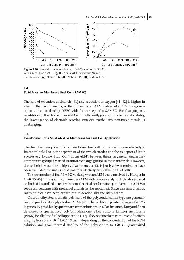
Finally the performance of a DEFC with an anode containing a higher amount ofplatinum (i.e. 60wt% instead of 30wt% for the previous experiments) were deter-mined with three Nafion membranes, N117, N115 and N112, of different thickness(180, 125 and 50mm, respectively) to investigate the effect of ethanol crossoverthrough the membrane. Figure 1.15 shows the ethanol crossover as measuredby following the ethanol concentration in a second cell compartment, initiallycontaining no ethanol, separated by the Nafion membrane from the first onecontaining 1M ethanol. The crossover rate through N117 is about half that throughN112. The better behavior of N117 is confirmed in Figure 1.16, showing thecomparative electrical characteristics of a DEFC having as electrolyte one of thethree Nafion membranes and an anode with a higher platinum loading (60% Pt–Sn(90 : 10)/XC72): the DEFC with N117 displays the highest OCV (0.8 V) and leads toa power density of 52mWcm�2 at 90 �C.
Figure 1.14 Fuel cell characteristics of a 25 cm2 DEFC recordedwith a 30% Pt–Sn (90 : 10) catalyst. Influence of the workingtemperature. Anode catalyst, 1.5mg cm�2 [30% Pt–Sn(90 : 10)/XC72]; cathode catalyst, 2mg cm�2 (40% Pt/XC72 fromE-TEK); membrane, Nafion 117; ethanol concentration, 1M.(&) 50 �C; (.) 70 �C; (~) 90 �C; (!) 100 �C; (^) 110 �C.
Figure 1.15 Behavior of different Nafion membranes. Ethanolpermeability measurements of different Nafion membranes.T¼ 25 �C. (&) Nafion 117; (.) Nafion 115; (~) Nafion 112.
28j 1 The Direct Ethanol Fuel Cell: a Challenge to Convert Bioethanol Cleanly into Electric Energy
1.4Solid Alkaline Membrane Fuel Cell (SAMFC)
The rate of oxidation of alcohols [41] and reduction of oxygen [41, 42] is higher inalkaline than acidic media, so that the use of an AEM instead of a PEM brings newopportunities to develop DEFC with the concept of a SAMFC. For that purpose,in addition to the choice of an AEM with sufficiently good conductivity and stability,the investigation of electrode reaction catalysts, particularly non-noble metals, ischallenging.
1.4.1Development of a Solid Alkaline Membrane for Fuel Cell Application
The first key component of a membrane fuel cell is the membrane electrolyte.Its central role lies in the separation of the two electrodes and the transport of ionicspecies (e.g. hydroxyl ion, OH�, in an AEM), between them. In general, quaternaryammonium groups are used as anion-exchange groups in these materials. However,due to their low stability in highly alkalinemedia [43, 44], only a fewmembranes havebeen evaluated for use as solid polymer electrolytes in alkaline fuel cells.The first methanol-fed PEMFCworking with an AEMwas conceived byHunger in
1960 [15, 45]. This system contained anAEMwith porous catalytic electrodes pressedon both sides and led to relatively poor electrical performance (1mAcm�2 at 0.25Vatroom temperature with methanol and air as the reactants). Since this first attempt,many studies have been carried out to develop alkaline membranes.Chloromethylated aromatic polymers of the polycondensation type are generally
used to produce strongly alkaline AEMs [46]. The backbone positive charge of AEMsis generally provided by quaternary ammoniumgroups. For instance, Fang and Shendeveloped a quaternized poly(phthalazinone ether sulfone ketone) membrane(PESK) for alkaline fuel cell applications [47]. They obtained amaximumconductivityranging from 5.2� 10�3 to 0.14 S cm�1 depending on the concentration of the KOHsolution and good thermal stability of the polymer up to 150 �C. Quaternized
Figure 1.16 Fuel cell characteristics of a DEFC recorded at 90 �Cwith a 60% Pt–Sn (90 : 10)/XC72 catalyst for different Nafionmembranes. (~) Nafion 117; (.) Nafion 115; (&) Nafion 112.
1.4 Solid Alkaline Membrane Fuel Cell (SAMFC) j29
polyether sulfone cardo polymers (QPES-C)were also studied by Li et al. [48, 49]. Theydetermined their conductivity and permeability to methanol. The conductivity of themembrane in 1.0MNaOH solution increased from 4.1� 10�2 to 9.2� 10�2 S cm�1
with increase in temperature from room temperature to 70 �C,whereas themethanoldiffusion coefficient inside the membrane increased from 5.7� 10�8 to 1.2� 10�7
cm2 s�1 over this temperature range, which is at least 40 times lower than those for aNafion membrane [49]. Although these membranes display high ionic conductivity,high thermal stability and low methanol permeability and therefore they may besuitable for use in direct alcohol alkaline fuel cells, no fuel cell data are available so farto compare with the current performance of DEFCs.Another important class ofmembranes studied for SAMFCapplication is prepared
from perfluorinated backbone polymers. Yu and Scott studied the electrochemicalperformance of an alkaline DMFCworking with an AEM [50]. The commercial ADP-Morgane membrane provided by Solvay consisted of a cross-linked fluorinatedpolymer carrying quaternary ammonium as exchange groups. Its thickness in thefully humidified state is 150–160mmand its specific resistance in 1MNaOHsolutionis close to 0.5W cm2. The fuel cell performance gave amaximumpower density closeto 10mWcm�2 with a Pt/C anode (60wt%Pt, 2.19mg cm�2 on non-Teflonized Toray90 carbon paper) and a Pt/C cathode (60wt% Pt, 2.07mg cm�2 on 20% wet-proofedToray 90 carbon paper), at a cell operating temperature of 60 �C and air pressure of2 bar in 2M methanol and 1MNaOH. This membrane was also used by Demar-connay and co-workers to compare the performance of a direct methanol fuel cellwith that of a direct ethylene glycol fuel cell [51, 52]. In both cases, they obtaineda maximum power density close to 20mWcm�2 at 20 �C, with similar electrodesmechanically pressed against the membrane (Pt 40wt%/C, 2.0mgPt cm�2),using pure oxygen at a pressure of 1 bar and 2M methanol in 1MNaOH. Varcoeand co-workers developed and characterized quaternary ammonium radiationgrafted alkaline anion-exchange membranes (AAEMs), such as poly(ethylene-co-tetrafluoroethylene) (ETFE) [53, 54] and poly(hexafluoropropylene-co-tetrafluor-oethylene) (FEP) with ion-exchange capacity as high as 1.35meqOH� g�1 andconductivity (as determined from electrochemical impedance spectroscopy) up to0.023� 0.001 S cm�1 at 50 �C, which are between 20 and 50% of the values for thecommercial acid-form Nafion115 membrane [55, 56]. In order to avoid carbonationof the electrode (carbonate precipitation) and to improve the long-term operationstability, they worked in fuel solutions without the undesirable addition of MþOH�.A peak power density of 130mWcm�2 for an H2/O2 fuel cell was obtained, while amaximum power density of 8.5mWcm�2 was obtained in a metal cation-freemethanol/O2 fuel cell working at 2–2.5 bar back-pressure and 80 �C.However, fluorine-containing polymers are expensive and the use of hydrocarbon-
onlymembranes (C–Hbackbone) could be interesting considering theirmanufactur-ing and availability. According to H€ubner and Roduner [57], at high in situ pH, theoxidative radical mechanism for polymer degradation is suppressed. Moreoveraccording to Matsuoka et al. [58], an alcohol penetrating the AEM may protect itfrom attack by peroxide. They used a polyolefin backbone chain from Tokuyama(Japan), on which was fixed tetraalkylammonium groups giving a membrane with
30j 1 The Direct Ethanol Fuel Cell: a Challenge to Convert Bioethanol Cleanly into Electric Energy

a thickness of 240mm. The conductivity of this membrane was close to 14mS cm�1.Alkaline direct alcohol fuel cell tests were performed with 1.0M of different alcohols(methanol, ethylene glycol, meso-erythritol, xylitol) in 1.0MKOH, with a 1.0mgPtcm�2 Pt/C catalyst as cathode and 4.5mgPt–Ru cm�2 Pt–Ru/C catalyst as anode.Ethylene glycol led to the highest power density (9.8mWcm�2) at 50 �C.Agel et al. [59] and Stoica et al. [60] also used non-fluorine-containing polymers,
such as polyepichlorhydrin homo- and copolymers. The ionic conduction of thesepolymers, which can be assimilated to polyether polymers, is insured by the presenceof quaternary ammonium groups as exchange groups. An ion-exchange capacity of1.3mol kg�1 and a conductivity of 1.3� 10�2 S cm�1 at 60 �C and RH¼ 98% werefound with ionomers based on polyepichlorhydrin copolymers using allyl glycidylether as cross-linking agent, but no fuel cell results were given. However, usinga polyepichlorhydrin homopolymer, H2/O2 fuel tests were carried out without andwith an interfacial solution made of poly(acrylic acid) and 1M KOH between theelectrodes and the membrane, giving maximum power densities close to 20 and40mWcm�2, respectively, at 25 �CwithPO2 ¼ PH2 ¼ 1 bar and electrodes containing0.13mgPt cm�2.The plasma route for the synthesis of conductive polymers was developed
recently [61]. Starting from a monomer containing triethylamine or triallylaminegroups, the membrane is synthesized by plasma polymerization of the monomervapor in a glow discharge to form a thin film partially composed of amine functions.Then, the amine functions are quaternized throughmethylation by immersion of theplasma film in methyl iodide solution. The structure of the plasma membranesconsists of a polyethylene-type matrix containing a mixture of primary, secondary,tertiary and quaternary amine groups. The polymers are amorphous, dense materi-als, highly cross-linked, and show a disorganized structure. Electrochemical imped-ance spectroscopic measurements revealed a rather low ion-exchange capacity andlow conductivity, but this could be counterbalanced by their low thickness (a fewmicrons).All the membranes considered were based on quaternary ammonium groups as
anion-exchange groups. However, these conductive groups may decompose inconcentrated alkaline solution following the Hofmann degradation reaction [43].It is crucial how these groups are attached to the polymer backbone, especially if oneconsiders that, during fuel cell operation, the pHmay increase up to 14. Under theseconditions, the presence of b-hydrogen atoms with respect to the nitrogen atommayrepresent a serious drawback for the stability in alkaline media [62]. The decomposi-tion of the backbone polymer matrix represents another factor to be taken intoaccount when designing an effective AEM. Basically, so far there does not exist anystable AEM in concentrated sodium hydroxide solution at high temperature.Although perfluorinated cation-exchange membranes show excellent stability in thepresence of oxidizing agents and concentrated hydroxide solution, a stable per-fluorinated amine is difficult to obtain because of the specific properties of fluorinecompounds, which readily decompose as follows:
Rf CF2NH2 !Rf CNþ 2HF ð1:51Þ
1.4 Solid Alkaline Membrane Fuel Cell (SAMFC) j31

Thus, some workers have investigated a completely different approach by usingpolymer films and introducing OH� conductivity by treating the films with concen-trated KOH. For example, poly(vinyl alcohol) (PVA) cross-linked with sulfosuccinicacid [63] or glutaraldehyde [64], doped with TiO2 and so on, [64], were developed byYang et al. The DMFC, consisting of an MnO2/C air cathode, a Pt–Ru black/C anodeand a PVA/TiO2 composite polymer membrane, allowed a maximum peak powerdensity of about 7.5mWcm�2 to be reached at 60 �C and 1 bar in 2M KOH þ 2MCH3OH solution. Xing and Savadogo [65] developed a 40mm thick alkali-dopedpolybenzimidazole (PBI) membrane, which exhibited ionic conductivity as high as9� 10�2 S cm�1 with 6MKOH-doped PBI at 90 �C. The performance of an H2/O2
SAMFC based on the KOH-doped PBI was similar to that of an H2/O2 PEMFCwithNafion 117, that is, close to 0.7–0.8Wcm�2.
1.4.2Anodic Catalysts in Alkaline Medium
Platinum-based catalysts are widely used in low-temperature fuel cells, so that up to40% of the elementary fuel cell cost may come from platinum, making fuel cellsexpensive. The most electroreactive fuel is, of course, hydrogen, as in an acidicmedium. Nickel-based compounds were used as catalysts in order to replaceplatinum for the electrochemical oxidation of hydrogen [66, 67]. Raney Ni catalystsappeared among the most active non-noble metals for the anode reaction in gasdiffusion electrodes. However, the catalytic activity and stability of Raney Ni alone asa basemetal for this reaction are limited. Indeed, Kiros and Schwartz [67] carried outdurability tests with Ni and Pt–Pd gas diffusion electrodes in 6MKOHmedium andshowed increased stability for the Pt–Pd-based catalysts compared with Raney Ni ata constant load of 100mAcm�2 and at temperatures close to 60 �C.Moreover, higheractivity and stability could be achieved by doping Ni–Al alloys with a few percent oftransition metals, such as Ti, Cr, Fe and Mo [68–70].In the case of an SAMFC, working with a Pt/C anode and fuelled with either
methanol or ethylene glycol, very similar power densities are achieved, that is, bothare close to 20mWcm�2 at 20 �C, as shown in Figure 1.17 [51].However, the most extensively investigated anode catalysts for DEFCs, in either
acidic or alkaline media, contain binary and ternary combinations based almostexclusively on Pt–Ru and Pt–Sn [71, 72]. The superior performance of these binaryand ternary electrocatalysts for the oxidation of ethanol, compared with Pt alone, isattributed to thebifunctionalmechanism [14] and to theelectronic interactionbetweenPt and the alloying metals [73]. Matsuoka et al. [74] studied the electro-oxidation ofdifferent alcohols and polyols for direct alkaline fuel cell applications using an AEM(from Tokumaya, Japan) functionalized with tetraalkylammonium groups as cationicgroups (thickness¼ 240mm). They obtained the best performance with ethyleneglycol, achieving a maximum power density close to 10mWcm�2 with a Pt–Rucatalyst at the anode. The relatively good reactivity of ethylene glycol (EG) makes it agood candidate for SAMFC applications. It is less toxic than methanol, its specificenergy is close to that of alcohols andboth carbons carryalcoholic groups. It can thenbe
32j 1 The Direct Ethanol Fuel Cell: a Challenge to Convert Bioethanol Cleanly into Electric Energy

assumed that its oxidation into oxalate species (�COO–COO�) can be achieved, asproposed by several authors [75–79]. Thus, 8mol of electrons are exchanged permoleofEG, insteadof 10 for complete oxidation intoCO2,whichmeans a faradaic efficiencyof 80%.Metals other than Pt, such as Pd [80, 81], Au [82], Sn, Cd andPb [83], display orenhance the catalytic activity towards EG electro-oxidation. Kadirgan et al. studied theeffect ofbismuthadatomsdepositedonplatinumsurfacebyunderpotential deposition(UPD) [84, 85]. They observed that the activity towards EG electro-oxidation isdecreased in acidic medium, whereas it is highly enhanced in alkaline medium.Cnobloch et al. used catalysts containing Pt–PdBi as anode for an AFCworking with6MKOH electrolyte [86]. A power of 225W with a 52-cell stack was achieved.Coutanceau et al. studied the electrocatalytic behavior of nanostructured Pt1� xPdx/C towards EGelectro-oxidation [51]. The highest electroactivity was foundwith a Pt:Pdatomic ratio of ca 1 : 1 for a metal loading on carbon of 20%, as shown in Figure 1.18.The synergetic effect of palladium when added to platinum was confirmed in anSAMFC by comparing the cell performance obtained at 20 �C using a Pt (20wt%)/Canode with that obtained using a Pt0.5Pd0.5 (20wt%)/C anode (Figure 1.19).
Figure 1.17 Cell voltage and power density vs current densitycurves for (a) 2M methanol in 4MNaOH solution; (b) 2Methylene glycol in 4MNaOH solution. Anode and cathodecatalysts, laboratory-made Pt (40wt%)/C prepared via theB€onnemann method, 2mgPt cm�2; commercial anionicmembrane, Morgane ADP from Solvay; T¼ 20 �C.
1.4 Solid Alkaline Membrane Fuel Cell (SAMFC) j33

Pt1�xBix/C and Pt1�(xþ y)PdxBiy/C catalysts were also studied for EG electro-oxidation in alkaline medium [52]. The highest electrocatalytic activity wasfound for the atomic compositions Pt0.9Bi0.1 and Pt0.45Pd0.45Bi0.1. On the basis ofelectrochemical, in situ IR reflectance spectroscopy and high-performance liquidchromatography (HPLC) measurements, it was shown that the modification ofplatinum and platinum-palladium catalysts with bismuth led to the decrease in theCO2 and formic acid yields (e.g. in the ability to break the C–C bond), whereas theyield in oxalic acid was increased, as shown in Figure 1.20a and b in the case of Pt/Cand Pt0.45Pd0.45Bi0.1, respectively. The different Bi-containing catalysts were used ina 5 cm2 SAMFC anode and compared with respect to the electro-oxidation of EG(Figure 1.21). Finally, the activity increases in the following order: Pd/C <Pt/C <Pt–Pd/C <Pt–Bi <C <Pt–Pd–Bi/C.
Figure 1.18 Polarization curves for the oxidationof 0.1Methyleneglycol in 0.2MNaOH solution recorded on (1) Pt0.25Pd0.75(20wt%)/C, (2) Pt0.5Pd0.5 (20wt%)/C and (3) Pt0.75Pd0.25(20wt%)/C; v¼ 50mV s�1; T¼ 20 �C. Catalysts were preparedaccording to the B€onnemann method.
Figure 1.19 (a) Cell voltage and (b) power density vs currentdensity curves recorded at 20 �C for the oxidation of 2M ethyleneglycol in 4MNaOH. Anodes: (~,~) Pt (20wt%)/C and (.,*)Pt0.5Pd0.5 (20wt%)/C. Laboratory-made cathode Pt (40wt%)/Cand anode catalysts prepared according to the B€onnemannmethod. All electrodes were loaded with 2mg cm�2 of metal.Anionic membrane, Morgane ADP from Solvay.
34j 1 The Direct Ethanol Fuel Cell: a Challenge to Convert Bioethanol Cleanly into Electric Energy

In the case of ethanol, Pd-based electrocatalysts seem to be slightly superior to Pt-based catalysts for electro-oxidation in alkaline medium [87], whereas methanoloxidation is less activated. Shen and Xu studied the activity of Pd/C promoted withnanocrystalline oxide electrocatalysts (CeO2, Co3O4, Mn3O4 and nickel oxides) in theelectro-oxidation of methanol, ethanol, glycerol and EG in alkaline media [88]. Theyfound that such electrocatalysts were superior to Pt-based electrocatalysts in terms ofactivity and poison tolerance, particularly a Pd–NiO/C electrocatalyst, which led to anegative shift of the onset potential of the oxidation of ethanol by ca 300mVcompared
Figure 1.20 (a) SPAIR spectra recorded duringthe electro-oxidation of ethylene glycol on Pt/C in0.2MNaOH þ 0.1M EG, at various potentials(each 100mV) from 130 to 1030mV/RHE (1)and chromatograms of the anodic outlet of aSAMFC working with a Pt/C anode without fuelrecirculation (2). (b) SPAIR spectra recordedduring the electro-oxidation of ethylene glycol on
Pt0.45Pd0.45Bi0.1/C in 0.2MNaOH þ 0.1M EG,at various potentials (each 100mV) from 130 to1030mV/RHE (1) and chromatograms of theanodic outlet of a SAMFC working with aPt0.45Pd0.45Bi0.1/C anode without fuelrecirculation (2). Electrocatalysts were preparedaccording to the �water-in-oil� microemulsionmethod.
1.4 Solid Alkaline Membrane Fuel Cell (SAMFC) j35

with a Pt/C electrocatalyst under the same experimental conditions. Recently,nanostructured electrocatalysts based on Fe–Co–Ni alloys, known with the acronymHYPERMEC [89], were synthesized. Electrodes containing these catalysts haveproved to be efficient in DEFCs with anion-exchange membranes, delivering powerdensities as high as 30–40mWcm�2 at room temperature in self-breathing cells andup to 60mWcm�2 at 80 �C in active systems. However, the catalyst durability isrelatively low due to the slow formation of a metal oxide layer on the metal particlesurface [90]. But preliminary data from CNR and ACTA show unequivocally that thecatalyst stability with timeunderworking conditions can be remarkably improved, upto several thousand hours, by decorating non-noblemetal catalysts with tiny amountsof palladium using original electroless or spontaneous deposition techniques [91].However, the oxidation reaction of alcohol is very difficult to activate at low
temperature, even in alkaline medium. This leads to poor cell performance. Otherhydrogen �reservoirs� were then studied for fuelling the SAMFC. Among them,NaBH4seems tobe themostpromisingone [in that case thedirect fuel cell is called thedirect borohydride fuel cell (DBFC)]. Indeed, the specific energy density of NaBH4 isabout 9.3 kWhkg�1 [92, 93], that is, higher than that of ethanol (8.0 kWhkg�1).However, several oxidation paths are possible:
. the direct oxidation path:
BH4� þ 8OH� !BO2
� þ 6H2Oþ 8e� E�NaBH4
¼ �1:24 V vs SHE
ð1:52Þ
. the indirect oxidation path:
BH4� þ 2H2O!BO2
� þ 4H2 ð1:53Þ
H2 þ 2OH� ! 2H2Oþ 2e� E�H2
¼ �0:83 V vs SHE ð1:54Þ
Figure 1.21 (a) Cell voltage and (b) powerdensity vs current density curves recorded at20 �C for the oxidation of 2M ethylene glycolin 4MNaOH. Anodes: (^, ^) Pt (40wt%)/C;(~, ~) Pt0.9Bi0.1 (50wt%)/C; (., *)Pt0.45Pd0.45Bi0.1 (50wt%)/C. Laboratory-made
cathode catalyst Pt (40wt%)/C preparedaccording to the B€onnemann method. Anodecatalysts prepared according to the �water-in-oil�microemulsion method. All electrodes wereloaded with 2mg cm�2 of metal. Anionicmembrane was Morgane-ADP from Solvay.
36j 1 The Direct Ethanol Fuel Cell: a Challenge to Convert Bioethanol Cleanly into Electric Energy

Assuming an electrode potential of 0.40 V vs SHE for oxygen reduction in a 1Malkaline medium (pH¼ 14), the direct path gives a cell voltage of 1.64 V, whereasthe indirect path leads to a cell voltage of 1.23 V. Therefore, catalysts which favorthe direct oxidation path are preferable in order to achieve higher cell performanceand higher energy efficiency. First, this implies working in alkaline solution withpH higher than 12 in order to limit the borohydride hydrolysis reaction [94].According to Elder and Hickling [95], only Pt, Pd and Ni, which display goodactivity for ionizing hydrogen, are able to oxidize borohydride at low overvoltages.Liu and co-workers [96, 97] achieved a power density of 35mWcm�2 at roomtemperature with a DBFC working with a nickel-based anode and a silver-basedcathode and of 290mWcm�2 at 60 �C with a mixture of surface-treated Zr–NiLaves phase alloys, AB2 (Zr0.9Ti0.1Mn0.6V0.2 Co0.1Ni1.1), and Pd deposited oncarbon as anode catalyst and platinum as cathode catalyst. However, these catalystsalso activate greatly the hydrolysis reaction of borohydride and therefore favor theindirect oxidation path. Gold is known to be an active metal for the electro-oxidation of borohydride and inactive for that of hydrogen. According to Chatenetet al. [98], gold allows an almost complete utilization of the reducer since around7.5 electrons per borohydride molecule are consumed with this material versus 4with platinum. However, the onset potential of BH4
� oxidation is shifted fromabout 0 V vs RHE with a Pt/C catalyst to about 0.35 V vs RHE with a Au/C catalyst,as shown in Figure 1.22.Subsequently, to obtain a powerful DBFC system with high efficiency, Latour and
co-workers proposed to manage the hydrolysis of borohydride to release an accuratequantity of molecular hydrogen such that the anode is able to oxidize at a givenfunctioning point [99]. For this purpose, they developed Pt–Ni catalysts and claimedthat the preliminary results were very promising [100].
Figure 1.22 Polarization curves for the oxidationof 0.01MNaBH4
in a 1MNaOH solution recorded on (1) Pt (50wt%)/C and (2) Au(50wt%)/C; v¼ 20mV s�1, W¼ 1000 rpm, T¼ 20 �C. Catalystswere prepared according to the �water in oil� microemulsionmethod.
1.4 Solid Alkaline Membrane Fuel Cell (SAMFC) j37

1.4.3Cathodic Catalysts in Alkaline Medium
Some electrocatalysts as alternatives to platinumhave been studied as active catalystsfor the oxygen reduction reaction (ORR) in alkaline media, such as palladium-basedcatalysts [101], ruthenium-based catalysts [102], iron-porphyrin or phthalocyaninecatalysts [103, 104], nickel and cobalt catalysts and nickel–cobalt–spinel catalysts[105–107], and especially manganese oxide-based catalysts [108–113]. In the case ofpalladium catalysts, the onset of the reductionwave is shifted by 50mV towardsmorenegative potentials in comparisonwith platinum electrocatalysts. At the beginning ofthe reduction wave, water is the main reaction product, whereas at higher cathodicoverpotentials, hydrogen peroxide becomes the main reaction product [101]. Ruthe-nium-based catalysts have shown poor performance in the oxygen reduction reactionbecause of the oxidefilm that is formed at the catalyst surface; as a result, the electrodebecomes inactive towards oxygen reduction [102]. To achieve good activity andstability towards ORR, iron porphyrins have to be pyrolyzed at about 700 �C. Then,the onset of the reduction wave is close to that obtained with a platinum catalyst.Moreover, the main reaction product remains water, even though some hydrogenperoxide is produced particularly at high overvoltages [103, 104]. The nickel- or cobalt-based electrocatalysts showed poor activity for ORR in alkaline media. Oxygenreduction on these materials occurs only via a two-electron mechanism, producinghydrogenperoxide as themainproduct.On the other hand, spinel of cobalt andnickeloxides, NixCo3� xO4 (0 < x < 1), showed better activity towards ORR, but the reactionmechanism via four electrons is not the main one and a large amount of hydrogenperoxide is formed [105–107].Manganese oxides have been extensively studied and itwas shown that the activity of these catalysts depends on the kind of oxides. Themostactive were the oxides a-MnO2, g-MnO2, Mn2O3 and MnOOH [108, 110, 111]. Thereaction mechanism on these catalysts involves the formation of the HO2
� interme-diate via the transfer of two electrons followed by a dismutation reaction of thisspecies into OH� and O2. The kinetics of the dismutation reaction is so fast,particularly on the MnOOH catalyst, that apparently four electrons are exchangedduring the ORR [109, 113]. Manganese oxides doped with Ni and/or Mg have alsobeen studied in terms of activity towards ORR [41, 112, 113]. It appeared that the useof nickel as doping agent allowed the best activity to be obtained. Indeed, thereduction wave was shifted by 100mV towards higher potentials and started only50mV lower than the reduction wave obtained at a platinum catalyst. However, themechanism of reaction remains the same as for manganese oxides alone, that is, viathe HO2
� dismutation reaction. Ag-based cathodes have an extensive history withalkaline fuel cells, for example Raney Ag-based cathodes were used by Siemens todevelop AFCs for military applications [114]. Moreover, Ag nanoparticles depositedon carbon are very easy to prepare and are known to be active towards the ORR [115].Demarconnay et al. used a method derived from that of the so-called �water-in-oil
microemulsion� method to prepare well dispersed Ag/C catalysts [116]. The onset ofthe oxygen reduction wave is only shifted by 50mV towards lower potentials on anAg/C catalyst comparedwith that obtained on a Pt/C catalyst and the limiting current
38j 1 The Direct Ethanol Fuel Cell: a Challenge to Convert Bioethanol Cleanly into Electric Energy

densities are very close for both catalysts (Figure 1.23), indicating that a similarmechanism is involved at least at high overvoltage. On the basis of rotating diskelectrode and rotating ring disk electrode experiments, it was shown that nanodis-persed Ag particles on carbon powder led to the reduction of molecular oxygenmainly to water, which is similar to the result obtained with platinum (see Table 1.3).According to the results obtained from rotating ring disk experiments and the
determination of Tafel slopes, it was concluded that the mechanism of oxygenelectroreduction on an Ag/C catalyst is similar to that on a Pt/C catalyst at highpotentials, that is, interesting potentials for fuel cell applications. Lee et al. alsoshowed that a 30wt% Ag electrode displayed the same electroactivity towards theORR as a 10wt% electrode and that the activity could be enhanced by doping Ag withMg [115].
Table 1.3 Total number of exchanged electrons nt as determined by RDEb and RRDEd experiments.
20wt% Ag/C
E (V vsRHE)
KL slopesa
at Pt/CKL slopesa
at Ag/C nRDEb jD
c (mA cm�2)( j 0R;l� jR;l)
c
(mA cm�2) nRRDEd p(H2O)
0.87 — — — 0.121 0 4 1000.77 6.06 — — 1.161 0 4 1000.67 5.91 6.70 3.6 2.735 10.1 3.9 96.40.57 6.17 6.76 3.5 3.605 21.6 3.9 94.20.47 6.22 6.79 3.5 3.967 34.2 3.8 91.70.37 6.07 6.71 3.6 4.236 40.2 3.8 90.90.27 6.10 6.60 3.7 4.448 49.2 3.8 89.5
Slopesa determined from the Koutecky–Levich (KL) plots; jD and jR are the disk and ring currentdensities, respectivelyc. p(H2O) is the fraction of water produced.
Figure 1.23 j(E) polarization curves recorded at a rotation rateW¼ 2500 rpm in an O2-saturated 0.1MNaOH electrolyte(T¼ 20 �C, v¼ 5mV s�1) for (dashed line) 20wt%Ag/C and (solidline) 20wt% Pt/C. Ag/C catalyst was prepared according to the�water-in-oil� microemulsion method, whereas Pt/C catalyst wasprepared using the B€onnemann method.
1.4 Solid Alkaline Membrane Fuel Cell (SAMFC) j39

Moreover, for methanol concentrations higher than 0.1M, the Ag/C cathodecatalyst displayed higher tolerance towards methanol than Pt/C (Figure 1.24a) andalmost total insensitivity towards the presence of EG (Figure 1.24b).Other platinum-free materials, such as cobalt and iron macrocycles, display total
insensitivity to the presence ofmethanol [117–119], whereasmanganese oxides showvery good tolerance towards the presence of NaBH4 [120]. However, for portableapplications, the fuel concentration has to be very high in order to increase the storedenergy density and hence the autonomy of the system. Nevertheless, the intrinsicelectroactivity of platinum free catalysts being lower than that of platinum, it could beinteresting to modify platinum catalysts with foreign metal elements, in order toimprove their tolerance towards the presence of the fuel and to increase theirelectrocatalytic activity towards the ORR. Numerous studies have shown that
Figure 1.24 j(E) polarization curves recorded on 20wt% Ag/C ata rotation rate W¼ 2500 rpm in an O2-saturated 0.1MNaOHelectrolyte in the presence of alcohol (T¼ 20 �C, v¼ 5mVs).(a) (—) Methanol-free electrolyte; (���������) 0.1M methanol;(�-�-�-�-�-) 0.5M methanol. (b) (—) EG-free electrolyte� (���������)0.1M EG; (�-�-�-�-�-) 0.5M EG. Catalysts were prepared accordingto the �water-in-oil� microemulsion method.
40j 1 The Direct Ethanol Fuel Cell: a Challenge to Convert Bioethanol Cleanly into Electric Energy

platinum-based binary alloyed electrocatalysts such as Pt–Fe, Pt–Co, Pt–Ni andPt–Crexhibit in acid electrolytes a higher catalytic activity for the ORR than pure plati-num [17, 121–124] and ahigher tolerance to thepresence of alcohol [18, 125–127]. Theobserved electrocatalytic enhancement was interpreted either by an electronic factor,that is, the change in the d-band vacancy of Pt upon alloying, and/or geometric effects(Pt coordination number and Pt�Pt distance). Both effects should enhance thereaction rate of oxygen adsorption and the breaking of the O–O bond duringthe reduction reaction. For example, the lattice parameter a0 in the case of a cubicPt–X catalyst (X¼ Fe, Co, Ni) decreases with increasing content of the alloyingcomponent X, leading to changes in the catalytic behavior. In the case of Pt–Ni alloys,the maximum electrochemical activity for the ORR is obtained with 30 at.% ofNi [128]. Lemire et al. also showed that the presence of highly uncoordinated atoms isvery important for CO adsorption at Au nanoparticles [129]. The same effect can alsobe true for oxygen adsorption at platinum nanoparticles. In addition to electronic,geometric, coordination and size effects, it was also proposed by Shukla et al. [130],that foreign metals, such as Cr, can protect platinum from oxidation and henceenhance the electrocatalytic activity of platinum towards the ORR. In alkalinemedium, Ad�zi�c et al. pointed out that the addition of bismuth adatoms to an Auelectrode led to greatly enhanced electrocatalytic activity towards the ORR [131].Demarconnay et al. prepared nanodispersed Pt–Bi catalysts with different atomic
compositions for the ORR [132]. They showed that a Pt0.8Bi0.2/C catalyst led to a shiftof the onset potential of the ORR towards higher potentials together with a highertolerance towards the presence of EG (Figure 1.25) compared with a pure platinumcatalyst. They explained this enhancement in activity and tolerance by the protectionof the platinum surface by bismuth oxides. In the potential range where the ORRstarts to occur, Bi2O5 surface species start to undergo a reduction reaction in Bi2O4,liberating oxide-free sites of platinum by decreasing the coverage by higher oxides of
Figure 1.25 j(E) polarization curves for the oxygen reductionreaction recorded in oxygen-saturated 0.2MNaOH: (1) at Pt/C;(2) at Pt/C in the presence of 0.1M EG; (3) at Pt0.8Bi0.2/C; (4) atPt0.8Bi0.2/C in the presence of 0.1M EG (v¼ 5mV s�1,W¼ 2500 rpm; T¼ 20 �C). Catalysts were prepared according tothe �water-in-oil� microemulsion method.
1.4 Solid Alkaline Membrane Fuel Cell (SAMFC) j41

bismuth. The newly accessible oxide-free platinum sites become active for oxygenreduction. Moreover, the liberation of oxide-free platinum sites in a potential rangewhere EG is not expected to adsorb at platinum leads to a higher tolerance of Pt–Bitowards the presence of EG.
1.5Conclusion
Ethanol is one of the most popular fuels produced from biomass (by fermentation ofsugar-containing crops or of numerous agricultural and municipal wastes) and hasa relatively high energy density (about two-thirds of that of gasoline and one-quarterof that of pure hydrogen). Its clean and efficient direct conversion into energy thenbecomes a challenge, particularly its conversion into electricity inside a fuel cell.The development of PEMFCs and more recently of SAMFCs brings new opportu-nities to the use of ethanol in a direct fuel cell, working either in acidic (PEM) oralkaline (AEM) medium.In an acidic medium, a PEMFC fed with ethanol allows power densities up to
60mWcm�2 to be reachedat high temperatures (80–120 �C), but this needsplatinum-based catalysts, which may prevent wider applications for portable electronic devices.On the other hand, in an alkaline medium, the activity of non-noble catalysts forethanol or ethylene glycol oxidation and oxygen reduction is sufficient to reach powerdensities of the order of 20mWcm�2 at room temperature. This opens up the hope ofdeveloping SAMFCs that are particularly efficient for large-scale portable applications.
References
1 Grove, W.R. (1839) PhilosophicalMagazine, 14, 127–130. Grove, W.R;(1843) Journal of the Franklin Institute, 35,277–280.
2 Gosselink, J.W. (2002) InternationalJournal ofHydrogenEnergy,27, 1125–1129.
3 Str€obel, R., Oszcipok, M., Fasil, M.,Rohland, B., J€orissen, L. and Garche, J.(2002) Journal of Power Sources, 105,208–215.
4 Tilak, B.V., Yeo, R.S. and Srinivasan, S.(1981) Comprehensive Treatise of Electro-chemistry, Vol. 3 (eds J.O�M. Bockris, B.E.Conway, E. Yeager and R.E. White),Plenum Press, New York, pp. 39–122.
5 Appleby, A.J. andFoulkes, F.R. (1989)FuelCell Handbook, Van Nostrand Reinhold,New York, pp. 203–500.
6 Lamy, C. and L�eger, J.-M. (1994) Journal dePhysique IV, 4, C1, 253–281.
7 Kordesch, K. and Simader, G. (1996) FuelCells and Their Applications, VCH VerlagGmbH, Weinheim.
8 Vielstich, W., Lamm, A. and Gasteiger,H. (2003) Handbook of Fuel Cells:Fundamental, Technology and Applications,Vol. 1, JohnWiley&Sons, Ltd,Chichester.
9 Bockris, J.O�M. and Reddy, A.K.N. (1972)Modern Electrochemistry, Vol. 2, PlenumPress, New York, p. 1141.
10 Sakellaropoulos, G.P. (1981) Advances inCatalysis, Vol. 30 (eds D.D. Eley, H. Pinesand P.B. Weisz), Academic Press, NewYork, p. 218.
11 Appleby, A.J., Conway, B.E. and Bockrisv,J.O�M. (1983) Comprehensive Treatise of
42j 1 The Direct Ethanol Fuel Cell: a Challenge to Convert Bioethanol Cleanly into Electric Energy

Electrochemistry, Vol. 7 (eds E. Yeager,S.U.M. Khan, R.E. White), PlenumPress,New York, pp. 173–239.
12 Krishtalik, L.I. (1970) Advances inElectrochemistry and ElectrochemicalEngineering, Vol. 7 (ed. P. Delahay),Interscience, New York.Trasatti, S. (1972)Journal of Electroanalytical Chemistry, 39,163–184.
13 Lamy, C., L�eger, J.-M., Srinivasan, S. andBockris, J.O�M. (2001) in Modern Aspectsof Electrochemistry, Vol. 34 (eds B.E.Conway and R.E. White), KluwerAcademic/PlenumPublishers, NewYork,pp. 53–118.
14 Watanabe, M. and Motoo, S. (1975)Journal of Electroanalytical Chemistry, 60,267–273; 275–283.
15 Dubau, L., Coutanceau, C., Garnier, E.,L�eger, J.-M. and Lamy, C. (2003) Journal ofApplied Electrochemistry, 33, 419–429.
16 Tarasevich, M.R., Sadkowski, A. andYeager, E. (1983) Comprehensive Treatise ofElectrochemistry, Vol. 7 (eds B.E. Conway,J.O�.M. Bockris, E. Yeager, S.U.M. Khanand R.E. White), Plenum Press,New York, pp. 301–398.
17 Ralph, T.R. and Hogarth, M.P., (2002)Platinum Metals Review, 46, 3–14.
18 Yang, H., Alonso-Vante, N., L�eger, J.-M.and Lamy, C. (2004) Journal of PhysicalChemistry. B, 108, 1938–1947.
19 Stevens, P., Novel-Catin, F.,Hammou,A.,Lamy, C. and Cassir, M. (2000) Trait�eG�enie Electrique,D3340 (edR.Bonnefille),Techniques de l�Ing�enieur, Paris,pp. 1–28.
20 Lamy, C., Kauffmann, J.-M. and Grenier,J.-C. (2003) Livre Blanc �ProgrammeENERGIE du CNRS, Minist�ere D�el�egu�e �ala Recherche et aux NouvellesTechnologies, Paris, pp. 21–41.
21 Jones, D.J., Rozi�ere, J., Marrony, M.,Lamy, C., Coutanceau, C., L�eger, J.-M.,Hutchinson, H. and Dupont, M. (2005)Fuel Cells Bulletin, 10, 12–15.
22 Lamy, C., Belgsir, E.M. and L�eger, J.-M.(2001) Journal of Applied Electrochemistry,31, 799–809.
23 Lamy, C., Lima, A., Le Rhun, V., Delime,F., Coutanceau, C. and L�eger, J.-M. (2002)Journal of Power Sources, 105, 283–296.
24 Rousseau, S., Coutanceau, C., Lamy, C.and L�eger, J.-M. (2006) Journal of PowerSources, 158, 18–24.
25 Rightmire, R.A., Rowland, R.L.,Boos, D.L. and Beals, D.L. (1964) Journalof the Electrochemical Society, 111, 242.
26 Iwasita, T. and Pastor, E. (1994)Electrochimica Acta, 39, 531.Iwasita, T.and Pastor, E. (1994) Electrochimica Acta,39, 547.
27 Wang, J., Wasmus, S. and Savinell, R.F.(1995) Journal of the ElectrochemicalSociety, 142, 4218.
28 Souza, J., Rabelo, F.J.B., de Moraes, I.R.and Nart, F.C. (1997) Journal ofElectroanalytical Chemistry, 420, 17.
29 Hitmi, H. (1992) PhD Thesis, Universityof Poitiers.
30 Delime, F., L�eger, J.-M. and Lamy, C.(1999) Journal of Applied Electrochemistry,29, 1249.
31 Rezzouk, A. (1994) PhD Thesis,University of Poitiers.
32 Bonarowska, M., Malinowski, A. andKarpinski, Z. (1999) Applied Catalysis A:General, 188, 145.
33 Aboul-Gheit, A.K., Menoufy, M.F. andEl-Morsi, A.K. (1990) Applied Catalysis,61, 283.
34 Hitmi, H., Belgsir, E.-M., L�eger, J.-M.,Lamy, C. and Lezna, R.O. (1994)Electrochimica Acta, 39, 407.
35 Perez, J.M., Beden, B.,Hahn, F., Aldaz, A.and Lamy, C. (1989) Journal ofElectroanalytical Chemistry, 262, 251.
36 Lamy, C., Rousseau, S., Belgsir, E.-M.,Coutanceau, C. and L�eger, J.-M. (2004)Electrochimica Acta, 49, 3901–3908.
37 Vigier, F., Coutanceau, C., Hahn, F.,Belgsir, E.M. and Lamy, C. (2004) Journalof Electroanalytical Chemistry, 563, 81–89.
38 Liu, P., Logadottir, A. and Nørskov, J.K.(2003) Electrochimica Acta, 48, 3731.
39 Morimoto, Y. and Yeager, E.B. (1998)Journal of Electroanalytical Chemistry,441, 77.
References j43

40 Shubina, T.E. and Koper, M.T.M. (2002)Electrochimica Acta, 47, 3621.
41 Yang, C.-C. (2004) International Journal ofHydrogen Energy, 29, 135–143.
42 Wang, Y., Li, L., Hu, L., Zhuang, L., Lu, J.and Xu, B. (2003) ElectrochemistryCommunications, 5, 662–666.
43 Iwamoto, T., Uetake, M. and Umeda,A. (1994) Hofman degradation ofstrong base anion exchange resin,Proceedings of the 68th AutumnAnnual Meeting of the Chemical Societyof Japan, Nagoya October 1994,p.472.
44 Matsui, K., Tobita, E., Sugimoto, K.,Kondo, K., Seita, T. and Akimoto, A.(1986) Journal of Applied Polymer Science,32, 4137–4143.
45 Hunger, H.F. (1960) Proceedings of theAnnual Power Sources Conference,Vol. 14, p.55.
46 Sata, T., Tsujimoto,M., Yamaguchi, T. andMatsusaki, K. (1996) Journal of MembraneScience, 112, 161–170.
47 Fang, J. and Shen, P.K. (2006) Journal ofMembrane Science, 285, 317–322.
48 Li, L., Zhang, J. and Wang, Y.X. (2003)Journal of Membrane Science, 226,159–167.
49 Li, L. and Wang, Y.X. (2005) Journal ofMembrane Science, 262, 1–4.
50 Yu, E.H. and Scott, K. (2004) Journal ofPower Sources, 137, 248–256.
51 Coutanceau, C., Demarconnay, L.,L�eger, J.-M. and Lamy, C. (2006) Journalof Power Sources, 156, 14–19.
52 Demarconnay, L., Brimaud, S.,Coutanceau, C. and L�eger, J.-M. (2007)Journal of Electroanalytical Chemistry, 601,169–180.
53 Varcoe, J.R., Slade, R.C.T., Yee, E.L.H.,Poynton, S.D. and Driscoll, D.J.(2007) Journal of Power Sources, 173,194–199.
54 Varcoe, J.R. and Slade, R.C.T. (2006)Electrochemistry Communications, 8,839–843.
55 Slade, R.C.T. and Varcoe, J.R. (2005) SolidState Ionics, 176, 585–597.
56 Herman,H. Slade, R.C.T. andVarcoe, J.R.(2003) Journal of Membrane Science, 218,147–163.
57 H€ubner, G. and Roduner, E. (1999)Journal of Materials Chemistry, 9,409–418.
58 Matsuoka, K., Iriyama, Y., Abe, T.,Matsuoka, M. and Ogumi, Z. (2005)Journal of Power Sources, 150, 27–31.
59 Agel, E., Bouet, J. and Fauvarque, J.F.(2001) Journal of Power Sources, 101,267–274.
60 Stoica, D. Ogier, L. Akrour, L. andAlloin, F. Fauvarque, J.-F. (2007)Electrochimica Acta, 53, 1596–1603.
61 Schiedaa, M., Rouald�es, S., Durand, J.,Martinent, A. and Marsacq, D. (2006)Desalination, 199, 286–288.
62 Varcoe, J.R. and Slade, R.C.T. (2005) FuelCells, 5, 187–200.
63 Yang, C.-C., Chiu, S.-J. and Chien, W.-C.(2006) Journal of Power Sources, 162,21–29.
64 Yang, C.-C. (2007) Journal of MembraneScience, 288, 51–60.
65 Xing, B. and Savadogo, O. (2000)Electrochemistry Communications, 2,697–702.
66 Kordesch, K.V. (1978) Journal of theElectrochemical Society, 125, 77C–88C.
67 Kiros, Y. and Schwartz, S. (2000) Journal ofPower Sources, 87, 101–105.
68 Ewe, H., Justi, E. and Schmitt, A. (1974)Electrochimica Acta, 19, 799–808.
69 Mund, K., Richter, G. and Von Sturm, F.(1977) Journal of the ElectrochemicalSociety, 125, 1–6.
70 Kenjo, T. (1985) Journal of theElectrochemical Society, 132, 383–386.
71 Vigier, F., Rousseau, S., Coutanceau, C.,L�eger, J.-M. and Lamy, C. (2006) Topics inCatalysis, 40, 111–121.
72 Song, S. and Tsiakara, P. (2006) AppliedCatalysis B: Environmental, 63, 187–193.
73 Frelink, T., Visscher, W. and Van Veen,J.A.R. (1996) Langmuir, 12, 3702–3708.
74 Matsuoka, K., Iriyama, Y., Abe, T.,Matsuoka, M. and Ogumi, Z. (2005)Electrochimica Acta, 51, 1085–1090.
44j 1 The Direct Ethanol Fuel Cell: a Challenge to Convert Bioethanol Cleanly into Electric Energy

75 Ewe, H., Justi, E. and Pesditschek, M.(1975) Energy Conversion, 15, 9–14.
76 Hauffe, W. and Heitbaum, J. (1978)Electrochimica Acta, 23, 299–304.
77 Santos, E. and Giordano, M.C. (1985)Electrochimica Acta, 30, 871–878.
78 Kadirgan, F., Bouhier-Charbonnier, E.,Lamy, C., L�eger, J.-M. and Beden, B.(1990) Journal of ElectroanalyticalChemistry, 286, 41–61.
79 de Lima, R.B., Paganin, V., Iwasita, T. andVielstich, W. (2003) Electrochimica Acta,49, 85–91.
80 Dalbay, N. andKadirgan, F. (1990) Journalof Electroanalytical Chemistry, 296,559–569.
81 Pattabiraman, R. (1997) Applied CatalysisA: General, 153, 9–20.
82 Beden, B., Kadirgan, F., Kahyaoglu, A.and Lamy, C. (1982) Journal ofElectroanalytical Chemistry, 135, 329–334.
83 Smirnova, N.W. Petrii, O.A. andGrzejdziak, A. (1988) Journal ofElectroanalytical Chemistry, 251, 73–87.
84 Kadirgan, F., Beden, B. and Lamy, C.(1982) Journal of ElectroanalyticalChemistry, 136, 119–138.
85 Kadirgan, F., Beden, B. and Lamy, C.(1983) Journal of ElectroanalyticalChemistry, 143, 135–152.
86 Cnobloch, H., Gr€oppel, D., Kohlm€uller,H., K€uhl, D. and Siemsen, G. (1979) inPower Sources 7. Proceedings of the 11thSymposium, Brighton, 1978, Vol. 24(ed. J. Thomson), Academic Press,London, p. 389.
87 Xu, C., Cheng, L., Shen, P.K. and Liu, Y.(2007) Electrochemistry Communications,9, 997–1001.
88 Shen, P.K. and Xu, C. (2006)Electrochemistry Communications, 8,184–188.
89 Bert, P. and Bianchini, C. (2006)Platinum-free electrocatalysts materials,European Patent EP 1 556 916 B1.
90 Bert, P., Bianchini, C., Giambastiani, G.,Miller, H., Santiccioli, S., Tampucci, A.and Vizza, F. (2006) Direct fuel cellscomprising a nitrogen compounds and
their use, Republica Italiana Dom. It.FI2006A000160.
91 Bert, P., Bianchini, C., Emiliani, C.,Giambastiani, G., Santiccioli, S.,Tampucci, A. and Vizza, F. (2006) Anodecatalysts made of noble metalspontaneously deposited ontonanostructured catalysts based ontransition metals, their preparation anduse and fuel cells containing them,Republica Italiana Dom. It.FI2006A000180.
92 Amendola, S.C., Onnerud, P., Kelly, M.T.,Petillo, P.J., Sharp-Goldman, S.L. andBinder,M. (1999) Journal of Power Sources,84, 130–133.
93 Li, Z.P., Liu, B.H., Arai, K., Asaba, K. andSuda, S. (2004) Journal of Power Sources,126, 28–33.
94 Mirkin, M.V. Yang, H. and Bard, A.J.(1992) Journal of the ElectrochemicalSociety, 139, 2212–2217.
95 Elder, J.P. and Hickling, A. (1962)Transactions of the Faraday Society, 58,1852–1864.
96 Liu, B.H., Li, Z.P., Arai, K. and Suda, S.(2005)Electrochimica Acta, 50, 3719–3725.
97 Li, Z.P., Liu, B.H., Arai, K. and Suda, S.(2005) Journal of Alloys and Compounds,404–406, 648–652.
98 Chatenet, M., Micoud, F., Roche, I. andChainet, E. (2006) Electrochimica Acta, 51,5459–5467.
99 Jamard, R., Latour, A., Salomon, J.,Capron, P. and Martinent-Beaumont, A.(2008) Journal of Power Sources, 176,287–292.
100 Latour, A. (2006) PhD Thesis, InstitutNational Polytechnique de Grenoble.
101 Yang, Y.-F., Zhou, Y.-H. and Cha, C.-S.(1995) Electrochimica Acta, 40,2579–2586.
102 Prakash, J. and Joachin, H. (2000)Electrochimica Acta, 45, 2289–2296.
103 Gojkovic, S.L., Gupta, S. andSavinell, R.F.(1999) Journal of ElectroanalyticalChemistry, 462, 63–72.
104 Gojkovic, S.L., Gupta, S. andSavinell, R.F.(2000) Electrochimica Acta, 45, 889–897.
References j45

105 Heller-Ling, N. Prestat, M. Gautier, J.-L.and Koenig, J.-F. (1997) ElectrochimicaActa, 42, 197–202.
106 Hu, Y., Tolmachev, Y.V. and Scherson,D.A. (1999) Journal of ElectroanalyticalChemistry, 468, 64–69.
107 Rashkova, V., Kitova, S., Konstantinov, I.and Vitanov, T. (2002) Electrochimica Acta,47, 1555–1560.
108 Ponce, J., Rehspringer, J.-L., Poillerat, G.and Gautier, J.-L. (2001) ElectrochimicaActa, 46, 3373–3380.
109 Matsuki, K. and Kamada, H. (1986)Electrochimica Acta, 31, 13–18.
110 Mao, L., Sotomura, T., Nakatsu, K.,Koshiba, N., Zhang, D. and Ohsaka, T.(2002) Journal of the ElectrochemicalSociety, 149, A504–A507.
111 Klapste, B., Vondrak, J. and Velicka,J. (2002) Electrochimica Acta, 47,2365–2369.
112 Yang, J. andXu, J.J. (2003)ElectrochemistryCommunications, 5, 306–311.
113 Mao, L., Zhang, D., Sotomura, T.,Nakatsu, K., Koshiba, N. and Ohsaka,T. (2003) Electrochimica Acta, 48,1015–1021.
114 Strasser, K. (2003) in Handbook of FuelCells – Fundamentals, Technology andApplications, Vol. 4 (eds W. Vielstisch,H.A. Gasteiger andA. Lamm), JohnWiley& Sons, Ltd, Chichester, p. 775.
115 Lee, H.-K., Shim, J.-P., Shim, M.-J., Kim,S.-W. and Lee, J.-S. (1996) MaterialsChemistry and Physics, 45, 238–242.
116 Demarconnay, L., Coutanceau, C. andL�eger, J.-M. (2004) Electrochimica Acta, 49,4513–4521.
117 Convert, P., Coutanceau, C., Crouigneau,P., Gloaguen, F. and Lamy, C. (2001)Journal of Applied Electrochemistry, 31,945–952.
118 Baranton, S., Coutanceau, C., Roux, C.,Hahn, F. and L�eger, J.-M. (2005) Journalof Electroanalytical Chemistry, 577,223–234.
119 Zagal, J.H. (2003) in Handbook of FuelCells – Fundamental, Technology and
Applications, Vol. 1 (eds W. VielstichA. Lamm and H.A. Gasteiger), JohnWiley and Sons, Ltd, Chichester,pp. 544–554.
120 Chatenet, M., Micoud, F., Roche, I.,Chainet, E. and Vondrak, J. (2006)Electrochimica Acta, 51, 5452–5458.
121 Paffet, M.T., Beery, J.G. and Gottesfeld, S.(1988) Journal of the ElectrochemicalSociety, 135, 1431–1436.
122 Beard, B.C. and Ross, P.N. (1990) Journalof the Electrochemical Society, 137,3368–3374.
123 Toda, T., Igarashi, H. and Watanabe, M.(1999) Journal of ElectroanalyticalChemistry, 460, 258–262.
124 Neergat, N., Shukla, A. and Gandhi, K.S.(2001) Journal of Applied Electrochemistry,31, 373–378.
125 Ralph, T.R. and Hogarth, M.P. (2002)Platinum Metals Review, 46, 146–164.
126 Yang, H., Coutanceau, C., L�eger, J.-M.,Alonso-Vante, N. and Lamy, C. (2005)Journal of Electroanalytical Chemistry, 576,305–313.
127 Koffi, R.C., Coutanceau, C., Garnier, E.,L�eger, J.-M. and Lamy, C. (2005)Electrochimica Acta, 50, 4117–4127.
128 Toda, T., Igarashi, H., Uchida, H.and Watanabe, M. (1999) Journalof the Electrochemical Society, 146,3750–3756.
129 Lemire, C. Meyer, R. Shaikhutdinov, S.and Freund, H.-J. (2003) AngewandteChemie International Edition, 43,118–121.
130 Shukla, A., Neergat, M., Parthasarathi, B.,Jayaram, V. and Hegde, M.S. (2001)Journal of Electroanalytical Chemistry, 504,111–119.
131 Ad�zi�c, R.R. (1984) Advances inElectrochemistry and ElectrochemicalEngineering, Vol. 13 (eds H. Gerisherand C.W. Tobia) Wiley-Interscience,New York, p 159.
132 Demarconnay, L., Coutanceau, C. andL�eger, J.-M. (2008) Electrochimica Acta, 53,3232–3241.
46j 1 The Direct Ethanol Fuel Cell: a Challenge to Convert Bioethanol Cleanly into Electric Energy