PART NO: 63636007 - The Atlantic Store NO: 63636007 1800 1800 1800 180 0 1800 0 +5 0-15 0 MIN:2.95...
11
70 177.8 PART NO: 63636007 180 0 180 0 180 0 180 0 180 0 180 0 +5 0 -15 0 MIN:2.95 in / 75 mm MAX:15.75 in / 400 mm MIN:2.95 in / 75 mm MAX:23.62 in / 600 mm MIN:2.95 x 2.95 in / 75 x 75 mm MAX:3.94 x 3.94 in / 100 x 100 mm MIN:3.07 in / 78 mm MAX:21.65 in / 550 mm MIN:3.07 in / 78 mm MAX:21.65 in / 550 mm +5 0 -15 0 ption 2 O Option 1 19 48.26
Transcript of PART NO: 63636007 - The Atlantic Store NO: 63636007 1800 1800 1800 180 0 1800 0 +5 0-15 0 MIN:2.95...

70 177.8
PART NO: 63636007
180 0
180 0
180 0
180 0
180 0
180 0
+5 0
-15 0
MIN
:2.95 in / 75 mm
MA
X:15.75 in / 400 mm
MIN:2.95 in / 75 mm
MAX:23.62 in / 600 mm
MIN:2.95 x 2.95 in / 75 x 75 mm
MAX:3.94 x 3.94 in / 100 x 100 mm
MIN:3.07 in / 78 mm
MAX:21.65 in / 550 mm
MIN:3.07 in / 78 mm
MAX:21.65 in / 550 mm
+50
-15 0
ption 2OOption 1
19 48.26

Articulating TV Wall Mount
2
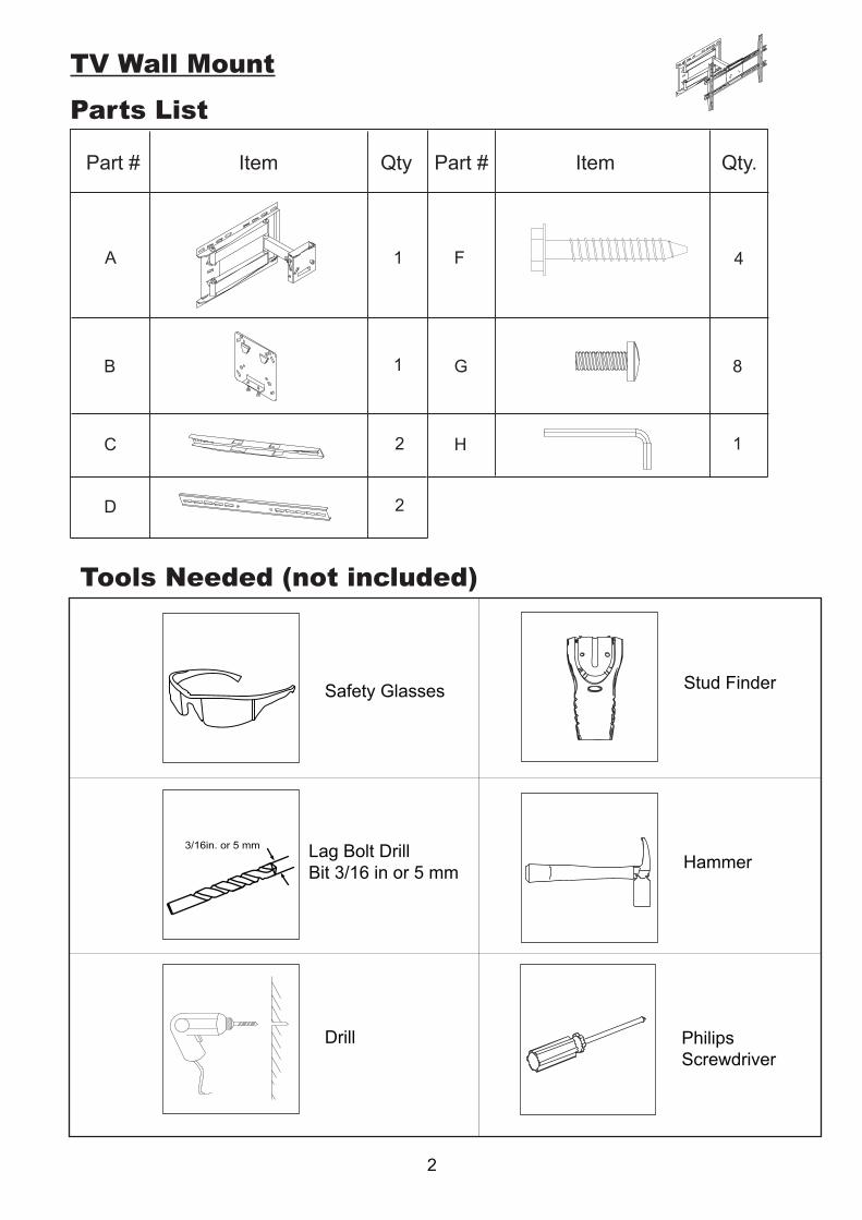
TV Wall Mount
Parts List
Part # Part # ItemItem QtyQty .
A
B
C
D
F
G
H
1
1
2
2
4
8
1
Safety Glasses
Lag Bolt DrillBit 3/16 in or 5 mm
Drill
Hammer
PhilipsScrewdriver
Stud Finder
Tools Needed (not included)
3/16in. or 5 mm

Caution:Never let children climb on product or play with product.
Do not sit or stand on furniture.
Do not place a weight that is heavier than the recommended load rating on the product surface.
If you do not understand these instructions, or have doubts about the safety of thisinstallation, contact customer service or call a qulified contractor. The manufactureis not liable for damage or injury caused by incorrect mounting, assembly or use.
The unit will hold a 19 to 70 in (48.26 to 177.8 cm) Plasma or LCD TV. The weightof the TV must not exceed 132 lbs (60 kgs). The wall must be capable of supportingfive times the weight of the TV plus the mount.
Improper handling can result in cuts and lacerations.
Images are for reference only.
3

4
TV Wall MountPLEASE CHOOSE BEST INSTALLATION OPTION BASED ON TV BRACKET PANELHOLE SPACING:
Option 1: 2.95 in x 2.95 in / 75 mm x 75 mm or 3.94 in x 3.94 in / 100 mm x 100 mm
16”/406mm
F
A
A
B
21
Remove TV mounting plate(B) from wall bracket(A).
This mount is designed to be attached into wood studs. DO NOT use wall anchors. using a stud finder,find the center of two adjacent studs. With a pencil, mark the hole locations at the bracket(A) as a template to mark the two remaining holes. Drill pilot holes at 4 pencil marks 2.5 in. (64mm) deep, using a 3/16 in. or 5 mm diameter drill bit.
Attach wall bracket(A) to the wall with 4 washers and screws(F).
B
3 4
Attach TV mounting plate(B) to the back ofthe TV, by selecting mounting hardware and then using instructions on Page 6.
We strongly recommend two people, one on each side,hold the TV. Carefully position the TV over the wallbracket(A) until ti locks in place. Tighten safety screws.

PLEASE CHOOSE BEST INSTALLATION OPTION BASED ON TV BACK PANELHOLES SPACING:
OPTION 2: (7.87 TO 23.6 ) in x 15.7 in / (200 to 600) mm x 400 mm
GG
C B DH
16”/406mm
F
A
21
This mount is designed to be attached into wood studs, DO NOT use wall anchors. using a stud finder, find the center of two adjacent studs. With a pencil, mark the hole location at the desired height, making sure you are level. Use wall bracket(A) as a template to mark the two remaining holes. Drill pilot holes at 4 pencil marks 2.5 in. (64mm) deep, using a 3/16 in. or 5 mm diameter drill bit.
Attach wall bracket(A) to the wall with 4 washers and screws(F).
We strongly recommend two people, one on each side, hold the TV. Carefully postion the TV over the wall bracket(A) until it locks in place. Tighten safety screws.
Measure the hole spacing on the bracket of your TV. Postion two TV mounts(C) onto horizontal attachment arms(D) at the same spacing. Using Allen wrench(H), attach both TV mounts(C) to attachment arms(D) with screws(G).
Using Allen wrench(H), attach TV mounting plate(B) to attachment arms(D) with 4 screws(G).
safety screws
3 4
Attach TV mounting assembly from STEP2 tothe back of the TV, by selecting mounting hardware and then using instructions on page 6.
5

6
TV Wall Mount
Mounting Hardware List Q’ty Mounting Hardware List Q’ty
M8 X 16MM
M6 X 12MM
M5 X 12
M4 X 12MM
M8 X 40
M6 X 35MM
M5 X 30MM
M4 X 30MM
4
4
4
4
4
4
4
4
M4 / M5 washer
M6 / M8 washer
M8 / M6 spacer
M4 / M5 spacer
4
4
4
4
I
J
K
L
M
N
O
P
Q
R
S
T
(7.87 to 23.6) in x 15.7 in(200 to 600) mm x 400 mm
2.95 in x 2.95 in / 75 mm x 75 mm 3.94 in x 3.94 in / 100 mm x 100 mm
OPTION 1 OPTION 2
TAKE EXTRA CARE AND PAY ATTENTION WHEN YOU FASTEN THE TV MOUNT(S) TO THE BACK TV PANEL IN STEP 3. MAKE SURE TO USE THE APPROPRIATE MOUNTING HARDWARE FOR YOUR TV.
1. Select the correct Mounting Hardware according to the screw hole size on your TV. Discard any remaining screws and spacers.
2. Carefully lay your TV face down on a non-abrasive surface, laying padding underneath it to protect the screen.
3. OPTION 1: Place the TV plate (B) in the appropriate position, making sure it is CENTERED on the back of TV and LEVEL.
OPTION 2: Place the right and left TV mounts in their appropriate positions, making sure they are CENTERED on the back of the TV and LEVEL with one another.
MM
MM

7
Surge Protector
Operation Instructions:
Electrical Rating: 15A, 120 VAC, 60Hz, 1800 Watts Surge Lines Protected: 3-Line (L-N, L-G, N-G) UL Clamping Voltage: L-N 400V, L-G 400V, N-G 400V Surge Energy Joule Rating: 2160 Joules Maximum Spike Current: 144,000 Amps (3 Line Total) Response Time: < 1 Nanosecond Max. Spike Voltage: 6KV
Attenuation: Up to 40dB
UL Listed to U.S Standards: UL 1449, UL 498A
Frequecy: 150KHz~100MHzEMI/RFI Noise Filter:
Technical Specification:
OPERATION INSTRUCTIONS
Plug Wall tap into Wall Receptacle
Connect electrical devices to the outlets

8
Surge Protector
Information/Functions:
This wall tap surge protector is designed to protect your electronic equipment from ACpower surges up to a certain level. It’s not a lightning arrestor, so it won’t afford protection while lightning strikes to nearby power lines, house, and/or service entrance antenna’s.
New X3 MOV (Metal Oxide Varistor) Technology:New designed component with improved material and surge functions absorb surges. Provides common and normal mode protection from high energy spikes.
Safety Shutdown Technology:Uses thermal fuses to power off your system, which protects against fire and other damage in the event of an extreme, extended over-voltage or when surge protection expires.
High-Frequency Capacitor:Reduces noise interference.
Surge Protected Outlets with 90° Rotating Design:Can be rotated to a different direction for easy usage with 3line surge protection
Each outlet pivots 90° (degrees) foryour convenience.
Grounded and Surge Protection LED indicators -
- Green light indicates your Surge Protection is working properly.
- Green light indicates your electrical wiring is properly grounded.
Do not plug the included surge protector into a power outlet that is different from the specs called out. If you don’t know or are not sure about the type of electrical power that is sup-plied to your home, please consult your local power company or a professional electrician.Use indoor and in dry locations. Not for use with aquariums and other water-related prod-ucts. This surge protector must be plugged directly into the power source and must not be ‘daisy chained’ together in serial fashion with other power strips, UPS, other surge protec-tors or extension chords. Risk of fire: Do not exceed electrical rating.
Don’t force your surge protector’s plug into an outlet that isn’t designed to accept a three-wire grounded-type AC plug (a three-pring plug). This plug is designed to be inserted into a grounded-type outlet only. If this plug doesn’t fit directly inside your outlet, do not attempt to force it in. Never attempt to take apart the plug in any way (or alter the power chord). Don’t attempt to defeat the grounding feature by using a 3-to-2 prong adapter. If you have ques-tions about grounding, consult your local power company or a qualified electrician.
Caution:

9
HDMI CablesInformation:
This Kit includes 2 HDMI™ cables
Supports Ethernet and 3DO.D.: 6.0mmDouble molding
Technical Specifications:Each HDMI cable measures 9 feet (2.74 m) in length.
1.4 Version
Cleaning Spray and Cloth
Instructions:The Screen Cleaning Kit in this package is comprised of 1 Bottle of Anti-Run Anti-Static Screen Cleaning Gel and 1 Cleaning Cloth
This special formula is designed for cleaning any type of screen, including LCD. The gel does not run down the screen.
Please shake bottle before spraying. Hold screen cleaner about 6 inches (15cm) away from the area to be cleaned. Spray screen, then use the included microfiber cloth to clean and polish. Shake or wash the cloth regularly to prevent collected dirt from making scratches. Do not spray excessive amount of cleaning gel.
Cleaning Cloth measures 7.87 sq. in. (20 sq. cm.)6.76 oz (200 ml)
Anti-Static Screen Cleaning Gel: IPA Free, 6.76 oz (200 ml)Cleaning Cloth: 7.87 sq. in (20 x 20 sq. cm.)
Technical Specifications:
Directions:
Caution: Keep away from children.
4 First aid measures:1. After inhalation: Supply fresh air; consult doctor in case of complaints.2. After skin contact: Immediately wash with water and soap and rinse thoroughly. If skin irritation continues, consult a doctor.3. After eye contact: Rinse opened eye for several minutes under running water. If symptoms persist a doctor.4. After swallowing: If symptoms persist consult doctor

2014
1.0 131210 #63636007
10