PART I UNDERSEA CABLE SYSTEM: TECHNICAL OVERVIEW & … · Elements of an Undersea Submarine Cable...
23
Proprietary and Confidential Slide 1 June 2008 Samia Bahsoun The David Ross Group Inc NANOG 43 - June 2008 PART I PART I UNDERSEA CABLE SYSTEM: UNDERSEA CABLE SYSTEM: TECHNICAL OVERVIEW & TECHNICAL OVERVIEW & COST CONSIDERATIONS COST CONSIDERATIONS
Transcript of PART I UNDERSEA CABLE SYSTEM: TECHNICAL OVERVIEW & … · Elements of an Undersea Submarine Cable...
Proprietary and Confidential Slide 1June 2008
Samia BahsounThe David Ross Group IncNANOG 43 - June 2008
PART IPART I
UNDERSEA CABLE SYSTEM:UNDERSEA CABLE SYSTEM:TECHNICAL OVERVIEW & TECHNICAL OVERVIEW & COST CONSIDERATIONSCOST CONSIDERATIONS
Proprietary and Confidential Slide 2June 2008
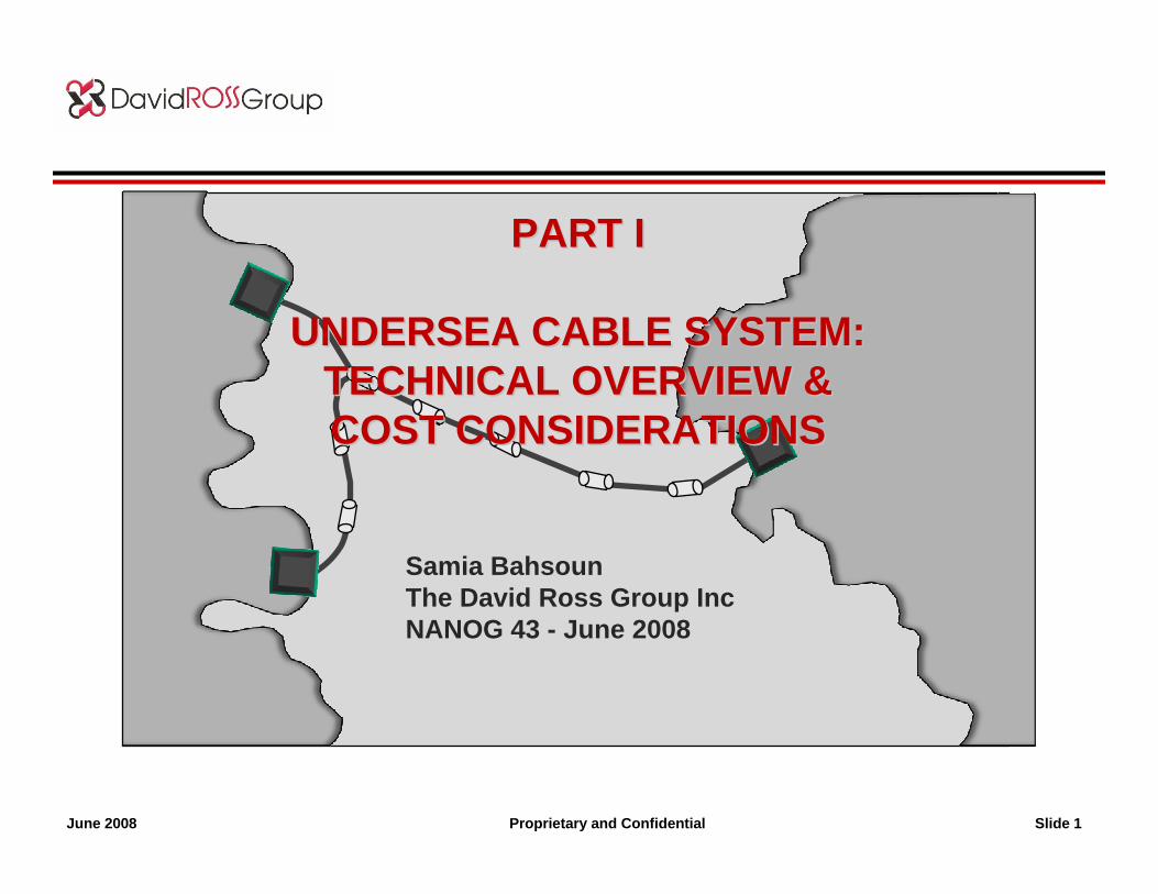
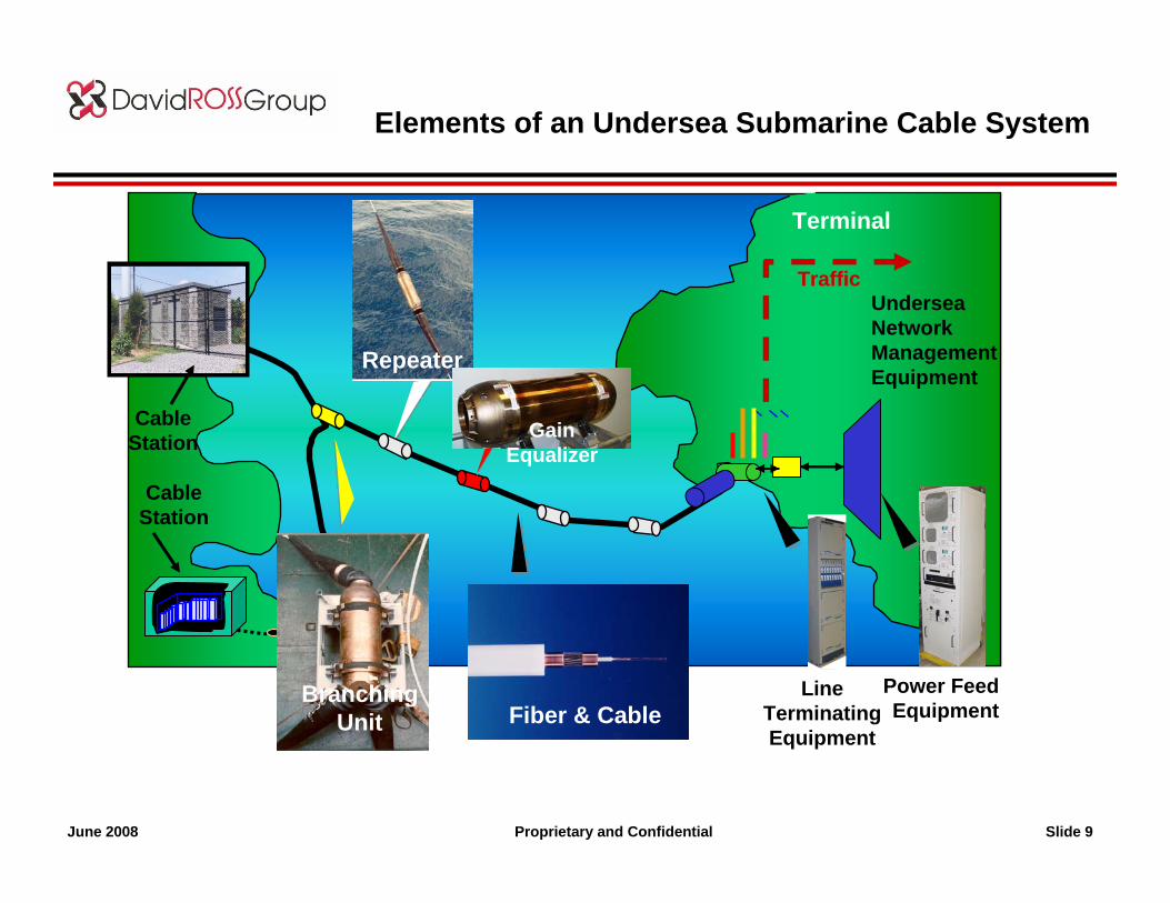
Elements of an Undersea Submarine Cable System
Power FeedEquipment
Terminal
TrafficUndersea Network ManagementEquipment
SDH
CableStation
Fiber & Cable
Repeater
BranchingUnit
LineTerminatingEquipment
CableStation
Proprietary and Confidential Slide 3June 2008
Undersea Cables
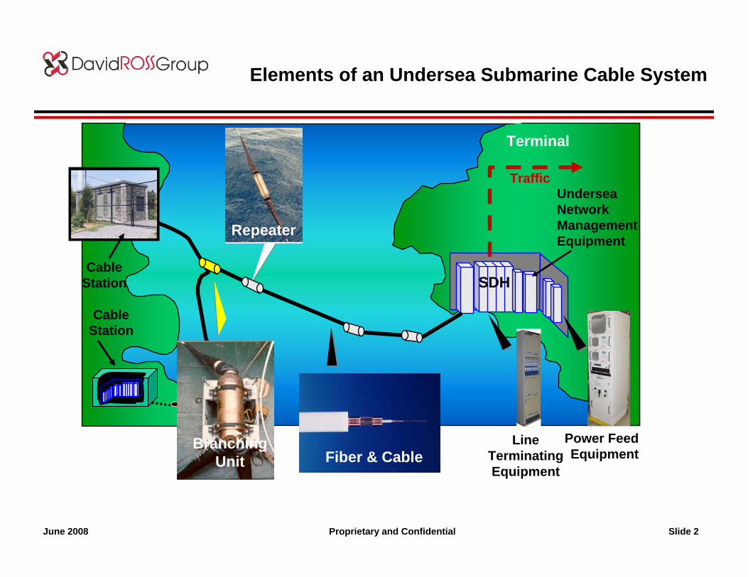
Armored Cable (LWA, SA, DA, etc)
Fibers
Steel Strength member
Copper Conductor
Polyethylene insulator
Steel Armor
Lightweight Cable: Serves as the core for all armored cables
• Contain & protect optical fibers and electrical conductor for 25 years or more in a marine environment.
• Design and construction complies with standard industry safety practices.
• Withstand the stresses and strains (temperature, tension, torsion, pressure, chemical exposure, bending/flexing) associated with deployment, recovery, repair and re-deployment operations with state-of-the-art cable handling equipment.
• Cable types suitable for deep (>1000m) and shallow (<1000m) water use; burial or surface lay.
• Cable power conductor suitable for carrying fault-locating signals.
• Deployment (LW) to 8,000m depth
• Non-threatening to the undersea environment
Fiber & Cable
Proprietary and Confidential Slide 4June 2008
Amplifier Pair Chassis
Pump UnitControl Circuit
Erbium Amplifiers
Supervisory
Heat Transfer Plate
Locking Plate
Power Supply
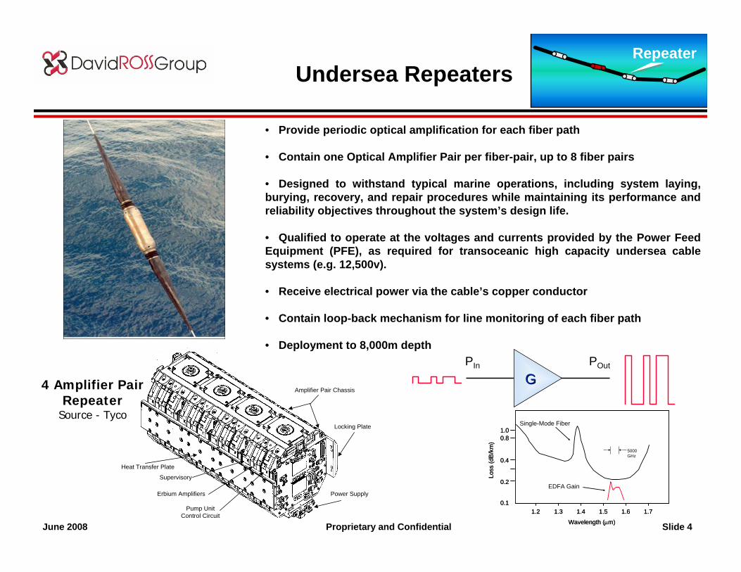
Undersea Repeaters
• Provide periodic optical amplification for each fiber path
• Contain one Optical Amplifier Pair per fiber-pair, up to 8 fiber pairs
• Designed to withstand typical marine operations, including system laying, burying, recovery, and repair procedures while maintaining its performance and reliability objectives throughout the system’s design life.
• Qualified to operate at the voltages and currents provided by the Power Feed Equipment (PFE), as required for transoceanic high capacity undersea cable systems (e.g. 12,500v).
• Receive electrical power via the cable’s copper conductor
• Contain loop-back mechanism for line monitoring of each fiber path
• Deployment to 8,000m depth
Repeater
4 Amplifier Pair Repeater
Source - Tyco
GGPIn POut
EDFA Gain
Single-Mode Fiber
1.2 1.3 1.4 1.5 1.6 1.7
Wavelength (µm)
Loss
(dB
/km
)
0.1
0.2
0.4
0.81.0
5000GHz
EDFA Gain
Single-Mode Fiber
1.2 1.3 1.4 1.5 1.6 1.7
Wavelength (µm)
Loss
(dB
/km
)
0.1
0.2
0.4
0.81.0
5000GHz
Proprietary and Confidential Slide 5June 2008
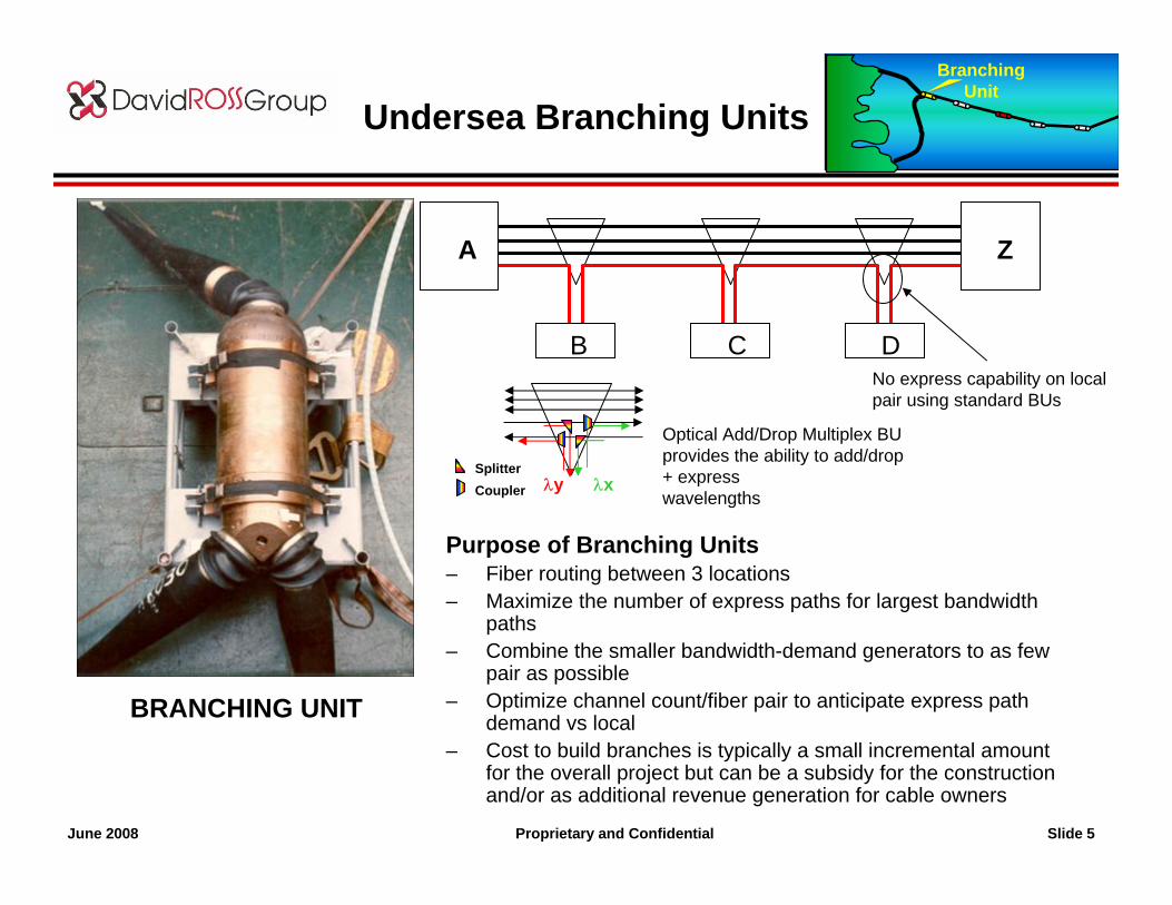
Undersea Branching Units
BRANCHING UNIT
Purpose of Branching Units– Fiber routing between 3 locations– Maximize the number of express paths for largest bandwidth
paths – Combine the smaller bandwidth-demand generators to as few
pair as possible– Optimize channel count/fiber pair to anticipate express path
demand vs local– Cost to build branches is typically a small incremental amount
for the overall project but can be a subsidy for the construction and/or as additional revenue generation for cable owners
No express capability on local pair using standard BUs
λy λxSplitterCoupler
Optical Add/Drop Multiplex BUprovides the ability to add/drop + expresswavelengths
A Z
B C D
BranchingUnit

Proprietary and Confidential Slide 6June 2008
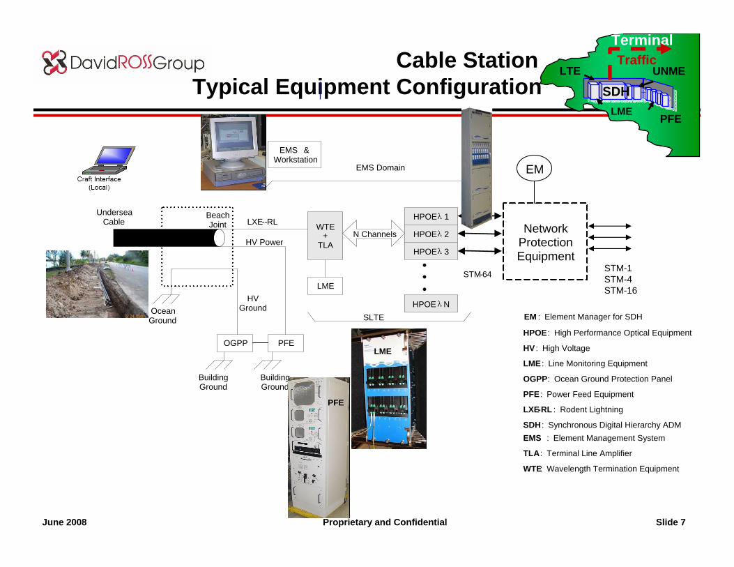
Cable Stations
- A typical cable station building is much like a Telco Central Or Gateway Office, except located close to the beach
- With infrastructure (racking, generators, batteries, distribution systems, alarm systems, etc) much like gateways
-If beachfront property scarce, or room exists in PoP station can be split into two:
- Container for PFE at beach- Transmission Gear at Gateway
Structural: Wind – Category 4 (up to 155 mph) minimumEarthquake – Seismic Zone 4
Security & Infrastructure:• Alarm & Security Systems• Fire/smoke alarms & Fire Suppression• Remote Monitoring Systems• A/C, DC Power, Backup Diesel, etc.
- Costs vary substantially, depending on size (a few million, to several million dollars)
- Associated permitting & construction can often be causeof project delays
TerminalTraffic
LTE
PFE
UNMEt
LME
SDH
Proprietary and Confidential Slide 7June 2008
Cable StationTypical Equipment Configuration
STM-1STM-4STM-16
SDH WTE
+ TLA
LME
N Channels
PFEOGPP
HPOE λ 1
HPOE λ 2
HPOE λ 3
EMS & Workstation
STM-64•••
LXE--RL
HV Power
Building Ground
Building Ground
Ocean Ground
HV Ground
Beach Joint
Undersea Cable
HPOE λN
EMS Domain
SLTE
Network ProtectionEquipment
EM
HPOE : High Performance Optical Equipment
HV : High Voltage
LME : Line Monitoring Equipment
OGPP : Ocean Ground Protection Panel
PFE : Power Feed Equipment
LXE-RL : Rodent Lightning
EMS : Element Management System
TLA : Terminal Line Amplifier
WTE: Wavelength Termination Equipment
SDH : Synchronous Digital Hierarchy ADM
EM : Element Manager for SDH
TerminalTraffic
LTE
PFE
UNMEt
LME
SDH
PFE
LME
Proprietary and Confidential Slide 8June 2008
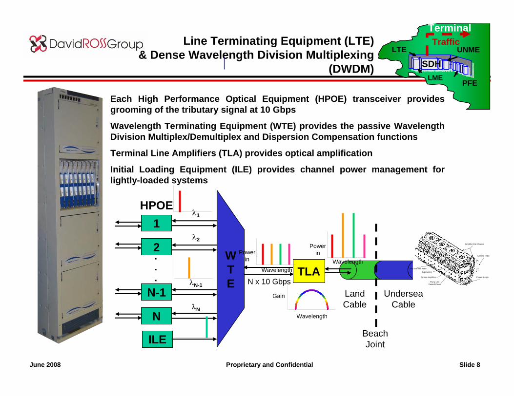
Line Terminating Equipment (LTE)& Dense Wavelength Division Multiplexing
(DWDM)
Each High Performance Optical Equipment (HPOE) transceiver provides grooming of the tributary signal at 10 Gbps
Wavelength Terminating Equipment (WTE) provides the passive Wavelength Division Multiplex/Demultiplex and Dispersion Compensation functions
Terminal Line Amplifiers (TLA) provides optical amplification
Initial Loading Equipment (ILE) provides channel power management for lightly-loaded systems
TerminalTraffic
LTE
PFE
UNMEt
LME
SDH
Gain
Wavelength
1
2
N
ILE
N-1λN-1
λN
.
.
.
λ1
λ2
HPOE
TLAN x 10 Gbps
WTE
LandCable
UnderseaCable
BeachJoint
Wavelength
Power in Wavelength
Power in
Amplifier Pair Chassis
Pump UnitControl Circuit
Erbium Amplifiers
Supervisory
Heat Transfer Plate
Locking Plate
Power Supply
Proprietary and Confidential Slide 9June 2008
Elements of an Undersea Submarine Cable System
Power FeedEquipment
Terminal
TrafficUndersea Network ManagementEquipment
CableStation
Fiber & Cable
Repeater
BranchingUnit
LineTerminatingEquipment
CableStation Gain
Equalizer
Proprietary and Confidential Slide 10June 2008
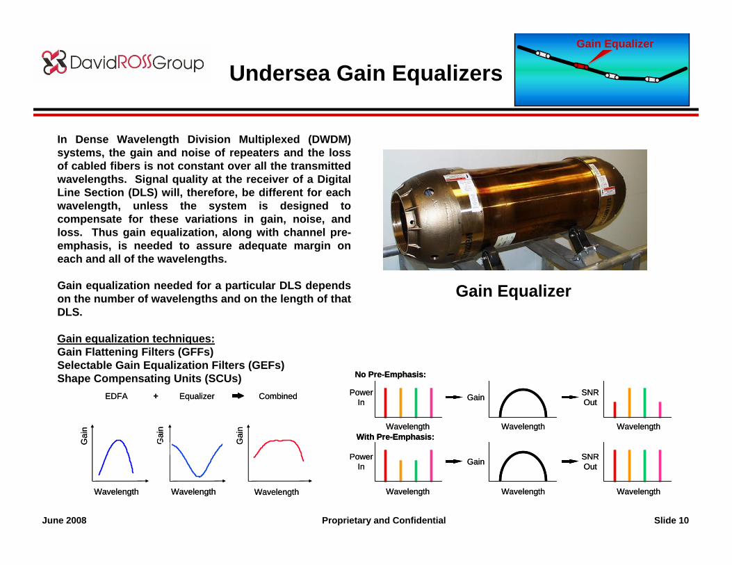
Undersea Gain Equalizers
Gain Equalizer
In Dense Wavelength Division Multiplexed (DWDM) systems, the gain and noise of repeaters and the loss of cabled fibers is not constant over all the transmitted wavelengths. Signal quality at the receiver of a Digital Line Section (DLS) will, therefore, be different for each wavelength, unless the system is designed to compensate for these variations in gain, noise, and loss. Thus gain equalization, along with channel pre-emphasis, is needed to assure adequate margin on each and all of the wavelengths.
Gain equalization needed for a particular DLS depends on the number of wavelengths and on the length of that DLS.
Gain equalization techniques:Gain Flattening Filters (GFFs)Selectable Gain Equalization Filters (GEFs)Shape Compensating Units (SCUs)
Gai
n
Wavelength Wavelength Wavelength
EDFA Equalizer Combined++
Gai
n
Gai
n
Gai
n
Wavelength Wavelength Wavelength
EDFA Equalizer Combined++
Gai
n
Gai
n
No Pre-Emphasis:
With Pre-Emphasis:
PowerIn
SNROutGain
PowerIn Gain SNR
Out
Wavelength Wavelength Wavelength
Wavelength Wavelength Wavelength
No Pre-Emphasis:
With Pre-Emphasis:
PowerIn
SNROutGain
PowerIn Gain SNR
Out
Wavelength Wavelength Wavelength
Wavelength Wavelength Wavelength
Gain Equalizer
Proprietary and Confidential Slide 11June 2008
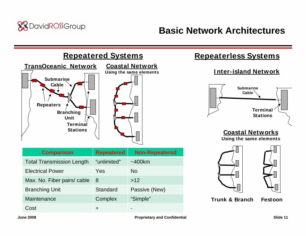
Basic Network Architectures
Repeaters
Branching Unit
SubmarineCable
TerminalStations
TransOceanic Network Coastal NetworkUsing the same elements
Coastal NetworksUsing the same elements
Trunk & Branch Festoon
Inter-island Network
SubmarineCable
TerminalStations
Repeatered Systems Repeaterless Systems
Comparison Repeatered Non-RepeateredTotal Transmission Length “unlimited” ~400km
Electrical Power Yes No
Max. No. Fiber pairs/ cable 8 >12
Branching Unit Standard Passive (New)
Maintenance Complex “Simple”
Cost + -
Proprietary and Confidential Slide 12June 2008
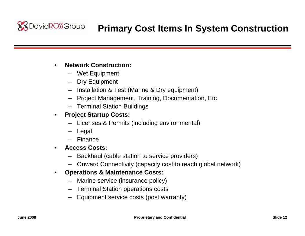
• Network Construction:– Wet Equipment– Dry Equipment– Installation & Test (Marine & Dry equipment)– Project Management, Training, Documentation, Etc– Terminal Station Buildings
• Project Startup Costs:– Licenses & Permits (including environmental)– Legal– Finance
• Access Costs:– Backhaul (cable station to service providers)– Onward Connectivity (capacity cost to reach global network)
• Operations & Maintenance Costs:– Marine service (insurance policy)– Terminal Station operations costs– Equipment service costs (post warranty)
Primary Cost Items In System Construction
Proprietary and Confidential Slide 13June 2008
Property of The David Ross Group Inc. All rights reserved
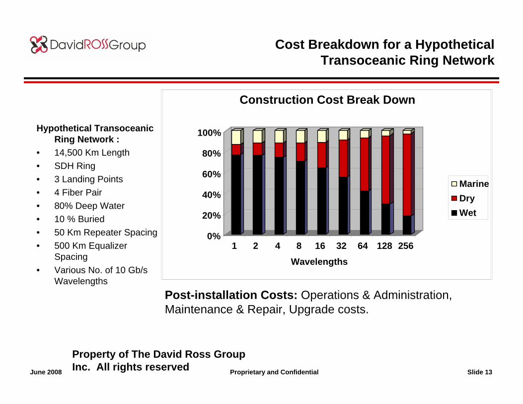
Cost Breakdown for a Hypothetical Transoceanic Ring Network
Construction Cost Break Down
0%
20%
40%
60%
80%
100%
1 2 4 8 16 32 64 128 256Wavelengths
MarineDry Wet
Hypothetical Transoceanic Ring Network :
• 14,500 Km Length• SDH Ring• 3 Landing Points• 4 Fiber Pair• 80% Deep Water• 10 % Buried• 50 Km Repeater Spacing• 500 Km Equalizer
Spacing• Various No. of 10 Gb/s
WavelengthsPost-installation Costs: Operations & Administration, Maintenance & Repair, Upgrade costs.
Proprietary and Confidential Slide 14June 2008
Summary
• A new undersea cable system typically:– Minimally cost 10’s of millions to construct, up to hundreds of millions for the very
long ones, and at least hundreds of thousands/year to operate & maintain thereafter
– Take 12-24 months to plan & construct, depending on the length, complexity of finance/regulatory situations, and supply market situation
– Utilizes well-proven products that perform for decades, and can be purchased from one of several qualified undersea suppliers
– Can provide huge amounts of transport capacity, starting with very little, and growing over time
– Provide high-quality transport that typically outperforms satellite quality
• When planning a new project, key issues that are sometimes overlooked include:– Regulatory issues, and time to get licenses/permits and form agreements with
landing parties in other countries
– The time it takes for financing, and the need to fund initial work with seed capital
– The cost and importance of access (backhaul & onward connectivity) options
– The schedule risks of civil construction & environmental permits
Proprietary and Confidential Slide 15June 2008
Samia BahsounThe David Ross Group IncNANOG 43 - June 2008
PART IIPART II
DEVELOPING AN DEVELOPING AN UNDERSEA CABLE SYSTEMUNDERSEA CABLE SYSTEM::
WHO GETS INVOLVED?WHO GETS INVOLVED?
Proprietary and Confidential Slide 16June 2008
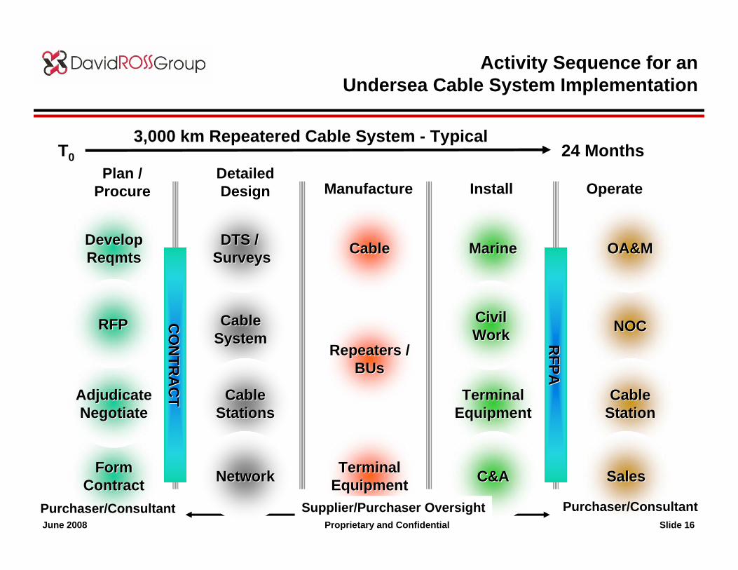
Plan / Procure
Detailed Design Manufacture Install Operate
CO
NTR
AC
TC
ON
TRA
CT
RFPA
RFPA
FormFormContractContract
AdjudicateAdjudicateNegotiateNegotiate
DevelopDevelopReqmtsReqmts
NOCNOC
OA&MOA&M
CableCableStationStation
CableCableSystemSystem
DTS / DTS / SurveysSurveys
CableCableStationsStations
NetworkNetwork
MarineMarine
TerminalTerminalEquipmentEquipment
C&AC&A
Repeaters /Repeaters /BUsBUs
TerminalTerminalEquipmentEquipment
CableCable
Activity Sequence for anUndersea Cable System Implementation
24 MonthsT03,000 km Repeatered Cable System - Typical
RFPRFP CivilCivilWorkWork
SalesSales
Purchaser/Consultant Supplier/Purchaser Oversight Purchaser/Consultant
Proprietary and Confidential Slide 17June 2008
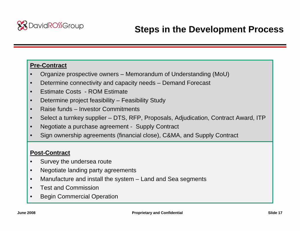
Steps in the Development Process
Pre-Contract • Organize prospective owners – Memorandum of Understanding (MoU)• Determine connectivity and capacity needs – Demand Forecast• Estimate Costs - ROM Estimate• Determine project feasibility – Feasibility Study• Raise funds – Investor Commitments• Select a turnkey supplier – DTS, RFP, Proposals, Adjudication, Contract Award, ITP• Negotiate a purchase agreement - Supply Contract• Sign ownership agreements (financial close), C&MA, and Supply Contract
Post-Contract• Survey the undersea route• Negotiate landing party agreements• Manufacture and install the system – Land and Sea segments• Test and Commission• Begin Commercial Operation
Proprietary and Confidential Slide 18June 2008
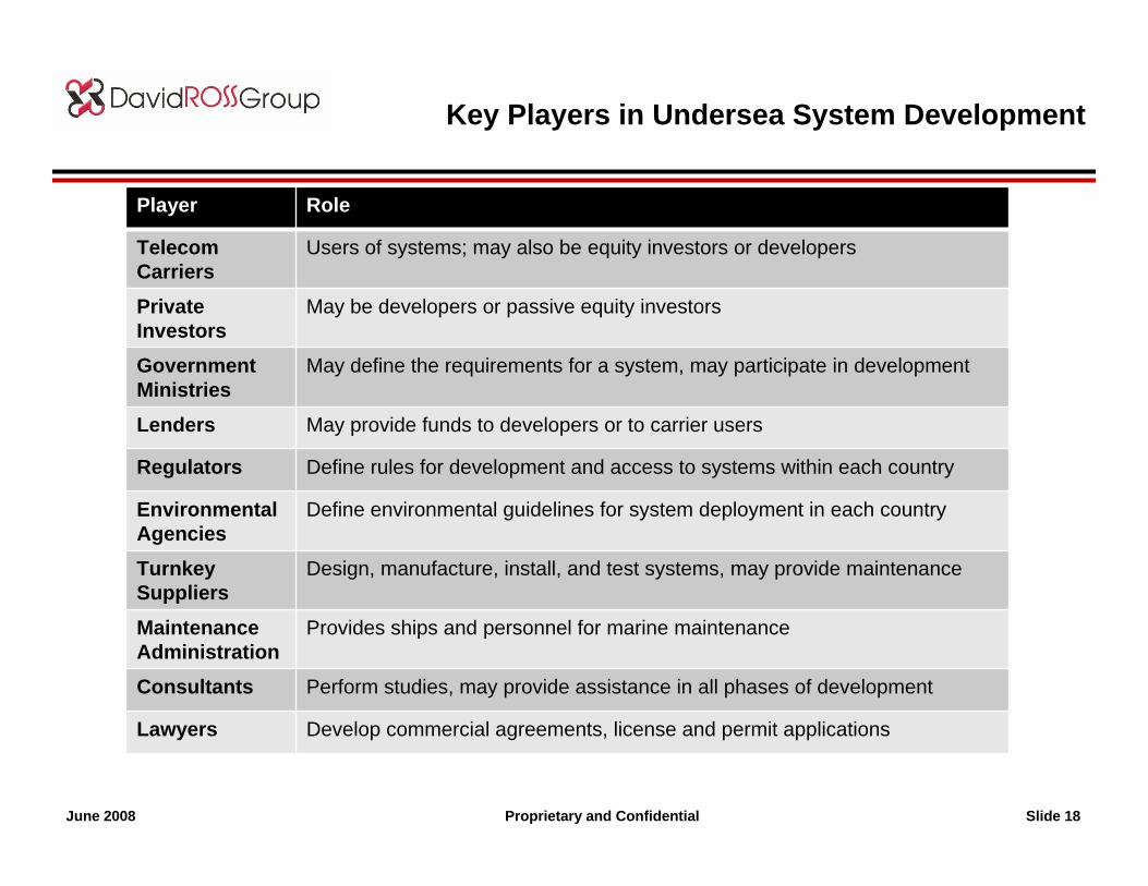
Key Players in Undersea System Development
Player Role
Telecom Carriers
Users of systems; may also be equity investors or developers
Private Investors
May be developers or passive equity investors
Government Ministries
May define the requirements for a system, may participate in development
Lenders May provide funds to developers or to carrier users
Regulators Define rules for development and access to systems within each country
Environmental Agencies
Define environmental guidelines for system deployment in each country
TurnkeySuppliers
Design, manufacture, install, and test systems, may provide maintenance
Maintenance Administration
Provides ships and personnel for marine maintenance
Consultants Perform studies, may provide assistance in all phases of development
Lawyers Develop commercial agreements, license and permit applications
Proprietary and Confidential Slide 19June 2008
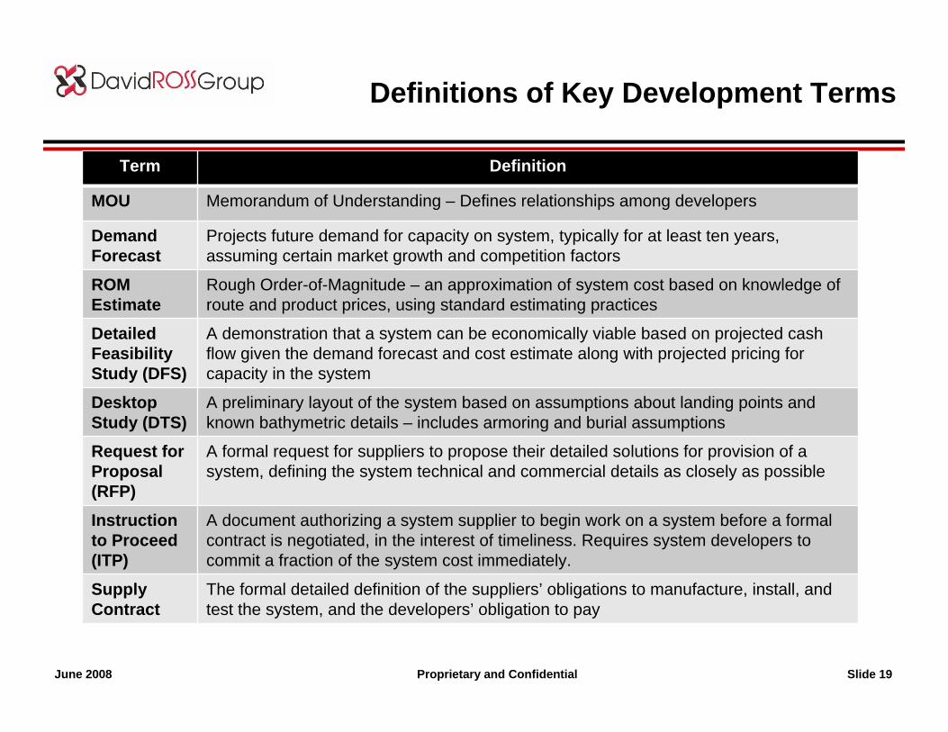
Definitions of Key Development Terms
Term Definition
MOU Memorandum of Understanding – Defines relationships among developers
Demand Forecast
Projects future demand for capacity on system, typically for at least ten years, assuming certain market growth and competition factors
ROM Estimate
Rough Order-of-Magnitude – an approximation of system cost based on knowledge of route and product prices, using standard estimating practices
Detailed Feasibility Study (DFS)
A demonstration that a system can be economically viable based on projected cash flow given the demand forecast and cost estimate along with projected pricing for capacity in the system
Desktop Study (DTS)
A preliminary layout of the system based on assumptions about landing points and known bathymetric details – includes armoring and burial assumptions
Request for Proposal (RFP)
A formal request for suppliers to propose their detailed solutions for provision of a system, defining the system technical and commercial details as closely as possible
Instruction to Proceed (ITP)
A document authorizing a system supplier to begin work on a system before a formal contract is negotiated, in the interest of timeliness. Requires system developers to commit a fraction of the system cost immediately.
Supply Contract
The formal detailed definition of the suppliers’ obligations to manufacture, install, and test the system, and the developers’ obligation to pay
Proprietary and Confidential Slide 20June 2008
Methods of Network Procurement
• Traditional Consortium
• Private Ownership
• Hybrids
Proprietary and Confidential Slide 21June 2008
Methods of Network Procurement
• Traditional Carrier Consortium– Joint development by carrier owners who share the facility– Dates to first undersea telecom cables of 1950s– Originally developed for pre-liberalization, one- carrier- per- country conditions– Adaptations for current conditions keep this a viable model worldwide– Financed by carriers from operating revenues– Philosophy: cooperate on facilities, compete on services– United Nations – style arrangement– Requires unanimous or majority agreement– Detailed Request for Quotations– Rigid competitive bidding – Lengthy Q&A, “Best & final offer” process– Carriers own capacity in proportion to investment– IRU sales by individual owners – Capacity Pricing: Determined by consortium
Proprietary and Confidential Slide 22June 2008
Methods of Network Procurement
• Private Networks– Development by private investors who sell capacity to carriers and
enterprises, otherwise known as carriers’ carriers– Flourished in the late 1990s telecom boom– Well suited to a liberalized, competitive market– Model has been applied worldwide in large and small markets– Philosophy: compete on facilities– Very informal Request for Quotations– Competitive offers and/or direct contract award – Entrepreneurs own network– Suppliers may share in ownership– IRU sales or capacity lease strategy, published pricing– Deals for volume purchasers– Sales through agents– Capacity Pricing: Determined by market conditions
Proprietary and Confidential Slide 23June 2008
Methods of Network Procurement
• Hybrid Networks– Development by a mix of carriers, enterprises, investors, and government– Primarily a 21st century development– Well suited to niche and developing markets with special needs– Philosophy: compete on facilities and services– Informal Request for Quotations– Competitive offers and/or direct contract award – Entrepreneurs and carriers own network– Suppliers may share in ownership– IRU sales or capacity lease strategy, published pricing– Deals for volume purchasers– Sales through agents– Capacity Pricing: May be consortium-like for owners, or determined by
market conditions