PART A – IMPACC COMMUNICATIONS...
94
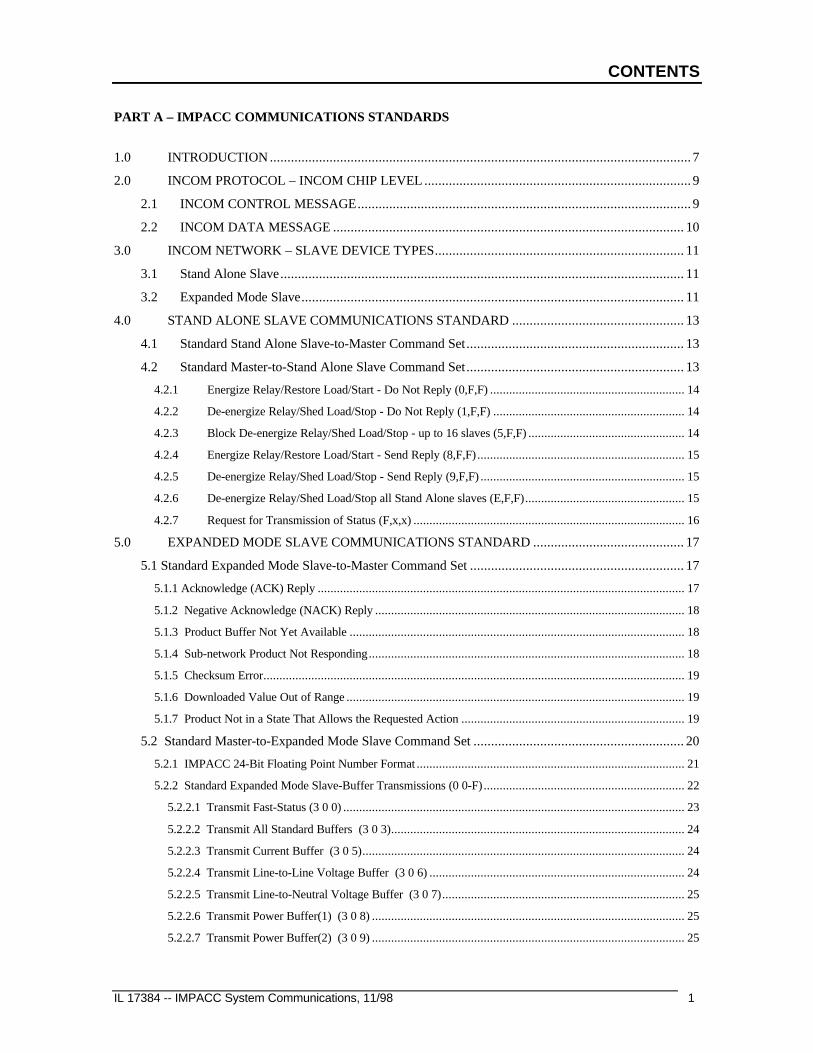
CONTENTS IL 17384 -- IMPACC System Communications, 11/98 1 PART A – IMPACC COMMUNICATIONS STANDARDS 1.0 INTRODUCTION ........................................................................................................................ 7 2.0 INCOM PROTOCOL – INCOM CHIP LEVEL ............................................................................ 9 2.1 INCOM CONTROL MESSAGE ............................................................................................... 9 2.2 INCOM DATA MESSAGE .................................................................................................... 10 3.0 INCOM NETWORK – SLAVE DEVICE TYPES....................................................................... 11 3.1 Stand Alone Slave ................................................................................................................... 11 3.2 Expanded Mode Slave ............................................................................................................. 11 4.0 STAND ALONE SLAVE COMMUNICATIONS STANDARD ................................................. 13 4.1 Standard Stand Alone Slave-to-Master Command Set .............................................................. 13 4.2 Standard Master-to-Stand Alone Slave Command Set .............................................................. 13 4.2.1 Energize Relay/Restore Load/Start - Do Not Reply (0,F,F) ............................................................. 14 4.2.2 De-energize Relay/Shed Load/Stop - Do Not Reply (1,F,F) ............................................................ 14 4.2.3 Block De-energize Relay/Shed Load/Stop - up to 16 slaves (5,F,F) ................................................. 14 4.2.4 Energize Relay/Restore Load/Start - Send Reply (8,F,F) ................................................................. 15 4.2.5 De-energize Relay/Shed Load/Stop - Send Reply (9,F,F) ................................................................ 15 4.2.6 De-energize Relay/Shed Load/Stop all Stand Alone slaves (E,F,F) .................................................. 15 4.2.7 Request for Transmission of Status (F,x,x) ..................................................................................... 16 5.0 EXPANDED MODE SLAVE COMMUNICATIONS STANDARD ........................................... 17 5.1 Standard Expanded Mode Slave-to-Master Command Set ............................................................. 17 5.1.1 Acknowledge (ACK) Reply ................................................................................................................... 17 5.1.2 Negative Acknowledge (NACK) Reply ................................................................................................. 18 5.1.3 Product Buffer Not Yet Available ......................................................................................................... 18 5.1.4 Sub-network Product Not Responding ................................................................................................... 18 5.1.5 Checksum Error.................................................................................................................................... 19 5.1.6 Downloaded Value Out of Range .......................................................................................................... 19 5.1.7 Product Not in a State That Allows the Requested Action ...................................................................... 19 5.2 Standard Master-to-Expanded Mode Slave Command Set ............................................................ 20 5.2.1 IMPACC 24-Bit Floating Point Number Format .................................................................................... 21 5.2.2 Standard Expanded Mode Slave-Buffer Transmissions (0 0-F) ............................................................... 22 5.2.2.1 Transmit Fast-Status (3 0 0) ........................................................................................................... 23 5.2.2.2 Transmit All Standard Buffers (3 0 3)............................................................................................ 24 5.2.2.3 Transmit Current Buffer (3 0 5) ..................................................................................................... 24 5.2.2.4 Transmit Line-to-Line Voltage Buffer (3 0 6) ................................................................................ 24 5.2.2.5 Transmit Line-to-Neutral Voltage Buffer (3 0 7) ............................................................................ 25 5.2.2.6 Transmit Power Buffer(1) (3 0 8) .................................................................................................. 25 5.2.2.7 Transmit Power Buffer(2) (3 0 9) .................................................................................................. 25
Transcript of PART A – IMPACC COMMUNICATIONS...
CONTENTS
IL 17384 -- IMPACC System Communications, 11/98 1
PART A – IMPACC COMMUNICATIONS STANDARDS
1.0 INTRODUCTION ........................................................................................................................ 7
2.0 INCOM PROTOCOL – INCOM CHIP LEVEL ............................................................................ 9
2.1 INCOM CONTROL MESSAGE............................................................................................... 9
2.2 INCOM DATA MESSAGE .................................................................................................... 10
3.0 INCOM NETWORK – SLAVE DEVICE TYPES....................................................................... 11
3.1 Stand Alone Slave................................................................................................................... 11
3.2 Expanded Mode Slave............................................................................................................. 11
4.0 STAND ALONE SLAVE COMMUNICATIONS STANDARD ................................................. 13
4.1 Standard Stand Alone Slave-to-Master Command Set.............................................................. 13
4.2 Standard Master-to-Stand Alone Slave Command Set.............................................................. 13
4.2.1 Energize Relay/Restore Load/Start - Do Not Reply (0,F,F) ............................................................. 14
4.2.2 De-energize Relay/Shed Load/Stop - Do Not Reply (1,F,F) ............................................................ 14
4.2.3 Block De-energize Relay/Shed Load/Stop - up to 16 slaves (5,F,F) ................................................. 14
4.2.4 Energize Relay/Restore Load/Start - Send Reply (8,F,F) ................................................................. 15
4.2.5 De-energize Relay/Shed Load/Stop - Send Reply (9,F,F) ................................................................ 15
4.2.6 De-energize Relay/Shed Load/Stop all Stand Alone slaves (E,F,F).................................................. 15
4.2.7 Request for Transmission of Status (F,x,x) ..................................................................................... 16
5.0 EXPANDED MODE SLAVE COMMUNICATIONS STANDARD ........................................... 17
5.1 Standard Expanded Mode Slave-to-Master Command Set ............................................................. 17
5.1.1 Acknowledge (ACK) Reply ................................................................................................................... 17
5.1.2 Negative Acknowledge (NACK) Reply ................................................................................................. 18
5.1.3 Product Buffer Not Yet Available ......................................................................................................... 18
5.1.4 Sub-network Product Not Responding................................................................................................... 18
5.1.5 Checksum Error.................................................................................................................................... 19
5.1.6 Downloaded Value Out of Range .......................................................................................................... 19
5.1.7 Product Not in a State That Allows the Requested Action ...................................................................... 19
5.2 Standard Master-to-Expanded Mode Slave Command Set ............................................................ 20
5.2.1 IMPACC 24-Bit Floating Point Number Format .................................................................................... 21
5.2.2 Standard Expanded Mode Slave-Buffer Transmissions (0 0-F) ............................................................... 22
5.2.2.1 Transmit Fast-Status (3 0 0) ........................................................................................................... 23
5.2.2.2 Transmit All Standard Buffers (3 0 3)............................................................................................ 24
5.2.2.3 Transmit Current Buffer (3 0 5)..................................................................................................... 24
5.2.2.4 Transmit Line-to-Line Voltage Buffer (3 0 6) ................................................................................ 24
5.2.2.5 Transmit Line-to-Neutral Voltage Buffer (3 0 7)............................................................................ 25
5.2.2.6 Transmit Power Buffer(1) (3 0 8) .................................................................................................. 25
5.2.2.7 Transmit Power Buffer(2) (3 0 9) .................................................................................................. 25

Contents
2 IL 17384 -- IMPACC System Communication, 11/98
5.2.2.8 Transmit Energy Buffer (3 0 A)...................................................................................................... 25
5.2.2.9 Transmit Saved Energy Buffer (3 0 B)........................................................................................... 26
5.2.2.10 Transmit Saved Reactive Energy Buffer (3 0 C)........................................................................... 27
5.2.2.11 Transmit Expanded Buffer (3 0 F) ................................................................................................ 28
5.2.2.9.1 Temperature Buffer (N=1) ....................................................................................................... 29
5.2.2.9.2 Peak Demand Currents(1) Buffer (N=2) ................................................................................... 30
5.2.2.9.3 Currents Buffer (N=3).............................................................................................................. 30
5.2.2.9.4 Line-to-line Voltage Buffer (N=4)............................................................................................ 30
5.2.2.9.5 Line-to-Neutral Voltage Buffer (N=5) ..................................................................................... 30
5.2.2.9.6 Power Buffer (N=6) ................................................................................................................ 31
5.2.2.9.7 Per-Phase Power Buffer (N=7) ................................................................................................ 31
5.2.2.9.8 System Energy Buffer (N=8)................................................................................................... 32
5.2.2.9.9 Total Harmonic Distortion Buffer (N=9).................................................................................. 33
5.2.2.9.10 Demand & Peak Demand Avg. Current Buffer (N=10)........................................................... 33
5.2.2.9.11 Demand & Peak Demand Currents Buffer (N=11).................................................................. 33
5.2.2.9.12 Peak Demand Power Buffer (N=12)....................................................................................... 34
5.2.2.9.13 Min/Max Current Buffer (N=13) ........................................................................................... 34
5.2.2.9.13 Min/Max Current Buffer (N=13) -- continued ........................................................................ 35
5.2.2.9.14 Min/Max L-L Voltage Buffer (N=14) .................................................................................... 35
5.2.2.9.15 Min/Max L-N Voltage Buffer (N=15).................................................................................... 35
5.2.2.9.15 Min/Max L-N Voltage Buffer (N=15) -- continued................................................................. 36
5.2.2.9.16 Min/Max PF-Displacement Buffer (N=16)............................................................................. 36
5.2.2.9.17 Min/Max PF-Apparent Buffer (N=17) ................................................................................... 37
5.2.2.9.18 Min/Max Power/Frequency Buffer (N=18) ............................................................................ 37
5.2.2.9.18 Min/Max Power/Frequency Buffer (N=18) -- continued ......................................................... 38
5.2.2.9.19 Min/Max Current %THD Buffer (N=19)................................................................................ 38
5.2.2.9.20 Transmit Min/Max Voltage %THD Buffer (N=20)................................................................. 39
5.2.2.9.21 Crest Factor Buffer (N=21).................................................................................................... 40
5.2.2.9.22 Min/Max Real Power Buffer (N=22) ..................................................................................... 40
5.2.2.9.23 Min/Max Reactive Power Buffer (N=23) ............................................................................... 41
5.2.2.9.24 Min/Max Voltampere (Apparent Power) Buffer (N=24) ......................................................... 41
5.2.2.9.25 Min/Max Currents Buffer (N=25).......................................................................................... 42
5.2.2.9.26 Min/Max Per-Phase Demand Current Buffer (N=26).............................................................. 42
5.2.2.9.27 Demand Power Buffer (N=27)............................................................................................... 42
5.2.2.9.28 Min/Max Voltage Buffer (N=28)........................................................................................... 43
5.2.2.9.29 Min/Max Power/Frequency/Power Factor Buffer (N=29) ....................................................... 43
5.2.2.9.30 Min/Max Current % THD Buffer (N=30)............................................................................... 43
5.2.2.9.31 Min/Max Voltage % THD Buffer (N=31) .............................................................................. 44
5.2.2.9.32 Min/Max Current THD Magnitude Buffer (N=32).................................................................. 44
5.2.2.9.33 Transmit Min/Max Voltage THD Magnitude Buffer (N=33)................................................... 45

Contents
IL 17384 -- IMPACC System Communications, 11/98 3
5.2.2.9.34 Transmit APC Energy Buffer (N=34) .................................................................................... 46
5.2.2.9.35 Transmit APC (Whole Load Center) Saved Energy Buffer (N=35) ......................................... 46
5.2.3 Transmit Product Specific Slave-Buffers (3 C 8-F) ................................................................................ 47
5.2.3.1 Transmit FLAGs Buffer (3 C 8) ..................................................................................................... 47
5.2.3.2 Transmit SETPOINTs Buffer (3 C 9) ............................................................................................ 48
5.2.3.3 Transmit (Unacknowledged) Time Stamped Event Data Buffer (3 C B)........................................... 49
5.2.3.3.1 Time-stamped Event Data Buffers Transmitted by Products that use the Offset Time Stamp.. 51
5.2.3.3.2 Time-stamped Event Data Buffers Transmitted by products that use the RTC (Real TimeClock) Time Stamp. ............................................................................................................................... 52
5.2.3.4 Transmit Expanded Buffer (3 C F)...................................................................................................... 53
5.2.4 Standard Expanded Mode Slave Action (3 D 0,1) .................................................................................. 54
5.2.4.1 Receive Slave Action Number (3 D 0)............................................................................................ 54
5.2.4.2 Process Sub-Network Command (3 D 1) ........................................................................................ 57
5.2.5 Standard Master-Buffer Transmissions (3 D 8-F)................................................................................... 59
5.2.5.1 Receive Current Date and Time (3 D 8)......................................................................................... 59
5.2.5.2 Receive INCOM Address (3 D 9)................................................................................................... 60
5.2.6 Product Specific Master-Buffer Transmissions (3 F 8-F) ........................................................................ 61
5.2.6.1 General Download (3 F 8).............................................................................................................. 61
5.2.6.2 Download Setpoints (3 F 9)............................................................................................................ 62
5.2.7 Broadcast Commands (D X X).............................................................................................................. 63
5.2.8 Transmit System Management Buffers (3 A 3-7) ................................................................................... 64
5.2.8.1 Transmit PONI configuration buffer (3 A 3) ................................................................................... 64
5.2.8.2 Transmit INCOM Slave-Interface Statistics buffer (3 A 4) .............................................................. 65
5.2.8.3 Transmit Product Specific Statistics buffer (3 A 5).......................................................................... 66
5.2.8.4 Transmit Sub-Network Master INCOM Statistics buffer (3 A 6) ..................................................... 67
5.2.8.5 Transmit Checksum of Previous Data Buffer (3 A 7) ...................................................................... 67
5.3 Standard IMPACC System Functions............................................................................................ 68
5.3.1 Sub-Network Master Demand Synchronization .............................................................................. 68
5.4 Programming Considerations for IMPACC Master Communications ............................................ 71
5.4.1 IMPACC Device Communications Standards................................................................................. 71
5.4.2 IMPACC Device Response Times.................................................................................................. 71
6.0 OVERVIEW .............................................................................................................................. 73
6.1 Register Definitions ................................................................................................................ 73
6.2 Initialization............................................................................................................................ 84
6.3 Mode 1 Operation ................................................................................................................... 84
6.3.1 Transmit Operation for Mode 1.............................................................................................................. 84
6.3.2 Receive Operation in Mode 1................................................................................................................ 85
6.4 Mode 2 Operation ................................................................................................................... 86
6.4.1 Transmit / Receive Operation for Mode 2............................................................................................... 86
6.5 PC Interrupt Usage.................................................................................................................. 88

Contents
4 IL 17384 -- IMPACC System Communication, 11/98
7.0 RS 232/ASCII – TO INCOM...................................................................................................... 89
7.1 ASCII Message Formats.......................................................................................................... 89
7.2 BCH Error and Data Flow Control ASCII Messages ................................................................ 92
7.2.1 BCH Error Characters.................................................................................................................... 92
7.2.2 Data Flow Control Characters ........................................................................................................ 93
7.3 RS232C Hardware Specifications............................................................................................ 94

Contents
IL 17384 -- IMPACC System Communications, 11/98 5
PART B – METERING PRODUCTS
100 COMMUNICATIONS PROTOCOL FOR THE IQ ANALYZER........................................... 100-1
101 COMMUNICATIONS PROTOCOL FOR THE IQ DATA AND IQ GENERATOR............... 101-1
102 COMMUNICATIONS PROTOCOL FOR THE IQ DATA PLUS .......................................... 102-1
103 COMMUNICATIONS PROTOCOL FOR THE IQ DATA PLUS II....................................... 103-1
104 COMMUNICATIONS PROTOCOL FOR THE IQ DP-4000 ................................................. 104-1
105 COMMUNICATIONS PROTOCOL FOR THE IQ ENERGY SENTINEL............................. 105-1
106 COMMUNICATIONS PROTOCOL FOR THE POWER SENTINEL.................................... 106-1
PART C – TRIP UNITS
200 COMMUNICATIONS PROTOCOL FOR THE DIGITRIP OPTIM....................................... 200-1
201 COMMUNICATIONS PROTOCOL FOR THE DIGITRIP RMS T700 & T800..................... 201-1
202 COMMUNICATIONS PROTOCOL FOR THE DIGITRIP RMS T810.................................. 202-1
203 COMMUNICATIONS PROTOCOL FOR THE DIGITRIP T910........................................... 203-1
204 COMMUNICATIONS PROTOCOL FOR THE DIGITRIP MV............................................. 204-1
205 COMMUNICATIONS PROTOCOL FOR THE IQ FP-3000.................................................. 205-1
PART D – MOTOR PROTECTION AND CONTROL
300 COMMUNICATIONS PROTOCOL FOR THE IQ 500 ......................................................... 300-1
301 COMMUNICATIONS PROTOCOL FOR THE IQ 1000 ....................................................... 301-1
302 COMMUNICATIONS PROTOCOL FOR THE IQ 1000 II.................................................... 302-1
303 COMMUNICATIONS PROTOCOL FOR THE MP-3000...................................................... 303-1
310 COMMUNICATIONS PROTOCOL FOR THE ADVANTAGE ............................................ 304-1
311 COMMUNICATIONS PROTOCOL FOR THE ADVANTAGE ACM................................... 305-1
312 COMMUNICATIONS PROTOCOL FOR THE ADVANTAGE CONTROL PONI................ 306-1
PART E – IMPACC PANEL MOUNTED OPERATOR PANELS
400 COMMUNICATIONS PROTOCOL FOR THE AEMII ......................................................... 400-1
401 COMMUNICATIONS PROTOCOL FOR THE ADVANTAGE CMU................................... 401-1
402 COMMUNICATIONS PROTOCOL FOR THE IQ CED ....................................................... 402-1
403 COMMUNICATIONS PROTOCOL FOR THE BIM............................................................. 403-1

Contents
6 IL 17384 -- IMPACC System Communication, 11/98
PART F – OTHER C-H IMPACC DEVICES
500 COMMUNICATIONS PROTOCOL FOR THE ADDRESSABLE RELAY ........................... 500-1
501 COMMUNICATIONS PROTOCOL FOR THE UNIVERSAL RTD ...................................... 501-1
502 COMMUNICATIONS PROTOCOL FOR THE AIM............................................................. 502-1
510 COMMUNICATIONS PROTOCOL FOR THE ACCUTROL 400......................................... 510-1
511 COMMUNICATIONS PROTOCOL FOR THE AF97 ........................................................... 511-1
520 COMMUNICATIONS PROTOCOL FOR THE MPCV NETWORK PROTECTOR .............. 520-1
530 COMMUNICATIONS PROTOCOL FOR THE IQ TRANSFER SWITCH ............................ 530-1
531 COMMUNICATIONS PROTOCOL FOR THE IQ TRANSFER SWITCH II......................... 531-1

Section 1
Introduction
IL 17384 -- IMPACC System Communications, 11/98 7
1.0 Introduction
The Cutler-Hammer Westinghouse INCOM (INdustrial COMmunications) Network is designed toprovide two-way communication between a network master and a variety of Cutler-HammerWestinghouse products such as breakers, digital meters, motor overload relays, etc. Control andmonitoring is carried out over a network consisting of dedicated twisted pair wires. The basis of thisnetwork is a semi-custom integrated circuit that has been developed to provide a simple, low-costinterface to the network. This integrated circuit provides the following network functions:
* Carrier generation and detection * Data modulation/demodulation * Address decoding * Generation and checking of a 5-bit cyclic redundant BCH error code
The INCOM communications protocol is master/slave. An INCOM network can have one masterand up to 1000 slaves. The INCOM communications protocol is based on 33-bit message packets.A typical INCOM network transaction consists of one or more 33-bit message packets transmittedby the master, and one or more 33-bit message packets transmitted by a slave in response.
Any computer or programmable device with either an RS 232c communications port or the PCXT/AT bus may function as an INCOM network master. An RS 232c based INCOM network masterrequires the use of a gateway device such as the Westinghouse MINT (Master INCOM NetworkTranslator) or RS 232 PONI. The gateway device converts the 33-bit binary messages used on theWestinghouse INCOM local area network to and from 10 byte ASCII encoded hexadecimal RS232c messages. An IBM compatible personal computer with at least one available ISA card slotcan alternatively use the Westinghouse CONI (Computer Operated Network Interface) forinterfacing to the INCOM network. An IBM XT or AT compatible personal computer canalternatively use the Westinghouse CONI (Computer Operated Network Interface) for interfacing tothe INCOM network. The CONI's direct PC-bus interface provides a more efficient networkinterface than the MINT.
This document is intended for users or OEMs who desire to develop their own software for anINCOM network master. It includes descriptions of the communications protocol at the INCOM chiplevel (ie. 33-bit messages) and the communications protocols at the product level (which arecombinations of 33-bit messages). Information on the CONI's PC interface and information on theMINT's ASCII translation are also provided.

Section 2 – INCOM Protocol – INCOM Chip Level
8 IL 17384 -- IMPACC System Communication, 11/98
This page intentionally left blank.
Section 2
INCOM Protocol – INCOM Chip Level
IL 17384 -- IMPACC System Communications, 11/98 9
2.0 INCOM Protocol – INCOM Chip Level
There are two basic types of INCOM messages:
* INCOM CONTROL Messages
* INCOM DATA Messages
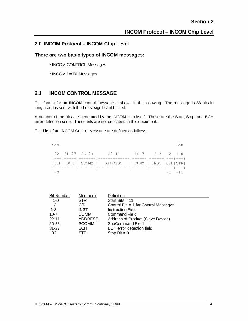
2.1 INCOM CONTROL MESSAGE
The format for an INCOM-control message is shown in the following. The message is 33 bits inlength and is sent with the Least significant bit first.
A number of the bits are generated by the INCOM chip itself. These are the Start, Stop, and BCHerror detection code. These bits are not described in this document.
The bits of an INCOM Control Message are defined as follows:
MSB LSB
32 31-27 26-23 22-11 10-7 6-3 2 1-0 +---+-----+-------+-------------+------+------+---+---+ |STP| BCH | SCOMM | ADDRESS | COMM | INST |C/D|STR| +---+-----+-------+-------------+------+------+---+---+ =0 =1 =11
Bit Number Mnemonic Definition . 1-0 STR Start Bits = 11 2 C/D Control Bit = 1 for Control Messages 6-3 INST Instruction Field10-7 COMM Command Field22-11 ADDRESS Address of Product (Slave Device)26-23 SCOMM SubCommand Field31-27 BCH BCH error detection field 32 STP Stop Bit = 0

Section 2 – INCOM Protocol – INCOM Chip Level
10 IL 17384 -- IMPACC System Communication, 11/98
2.2 INCOM DATA MESSAGE
The format for an INCOM-Data message is shown in the following. The message is 33 bits inlength and is sent with the Least significant bit first.
A number of the bits are generated by the INCOM chip itself. These are the Start, Stop, and BCHerror detection code. These bits are not described in this document.
The bits of an INCOM Data Message are defined as follows:
MSB LSB 32 31-27 26-19 18-11 10-3 2 1-0 +---+-----+---------+---------+---------+---+---+ |STP| BCH | BYTE2 | BYTE1 | BYTE0 |C/D|STR| +---+-----+---------+---------+---------+---+---+ =0 =0 =11
BIT NUMBER Mnemonic Definition 1-0 STR Start Bits = 11 2 C/D Control Bit = 0 for Data Messages 10-3 BYTE0 8-bit data field (Bit 3 = B0) 18-11 BYTE1 8-bit data field (Bit 11 = B0) 26-19 BYTE2 8-bit data field (Bit 18 = B0) 31-27 BCH BCH error detection field 32 STP Stop Bit = 0
Section 3
INCOM Network – Slave Device Types
IL 17384 -- IMPACC System Communications, 11/98 11
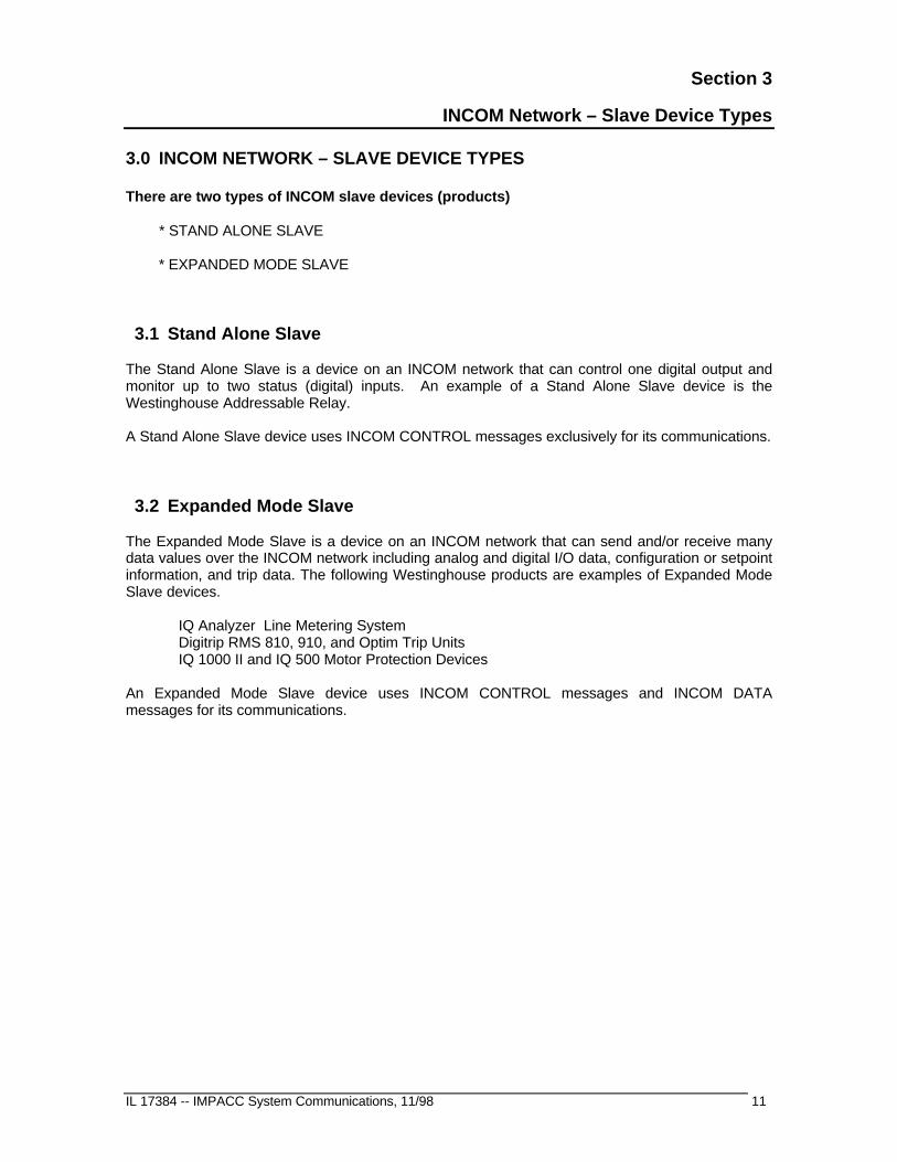
3.0 INCOM NETWORK – SLAVE DEVICE TYPES
There are two types of INCOM slave devices (products)
* STAND ALONE SLAVE
* EXPANDED MODE SLAVE
3.1 Stand Alone Slave
The Stand Alone Slave is a device on an INCOM network that can control one digital output andmonitor up to two status (digital) inputs. An example of a Stand Alone Slave device is theWestinghouse Addressable Relay.
A Stand Alone Slave device uses INCOM CONTROL messages exclusively for its communications.
3.2 Expanded Mode Slave
The Expanded Mode Slave is a device on an INCOM network that can send and/or receive manydata values over the INCOM network including analog and digital I/O data, configuration or setpointinformation, and trip data. The following Westinghouse products are examples of Expanded ModeSlave devices.
IQ Analyzer Line Metering SystemDigitrip RMS 810, 910, and Optim Trip UnitsIQ 1000 II and IQ 500 Motor Protection Devices
An Expanded Mode Slave device uses INCOM CONTROL messages and INCOM DATAmessages for its communications.

Section 3 – INCOM Network – Slave Device Types
12 IL 17384 -- IMPACC System Communication, 11/98
This page intentionally left blank.
Section 4
Stand Alone Slave Communications Standard
IL 17384 -- IMPACC System Communications, 11/98 13
4.0 STAND ALONE SLAVE COMMUNICATIONS STANDARD
4.1 Standard Stand Alone Slave-to-Master Command Set
There are seven commands that an INCOM network master may send to a Stand Alone Slavedevice. Three of the commands (INST = 8,9, and F) require the slave to send a reply. A StandAlone slave device's reply is always a control messages of following format:
C/D = 1 INST = INST value sent by the master (echoed) COMM = COMM value sent by the master (echoed) ADDRESS= ADDRESS of slave SCOMM = SCOMM value sent by the master (echoed) except bits 2 and 3 of the SCOMM
field (bits 25 and 26 of the 33-bit message) contain the status of the device (two status bits or digital inputs)
4.2 Standard Master-to-Stand Alone Slave Command Set
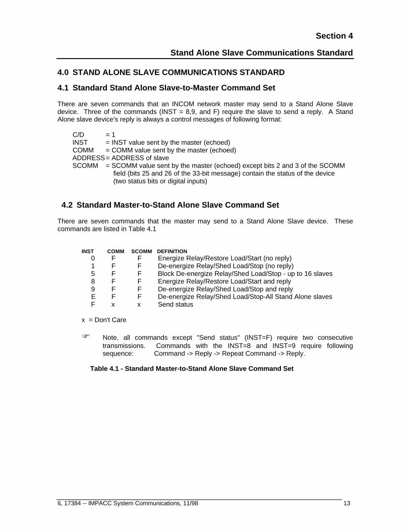
There are seven commands that the master may send to a Stand Alone Slave device. Thesecommands are listed in Table 4.1
INST COMM SCOMM DEFINITION 0 F F Energize Relay/Restore Load/Start (no reply) 1 F F De-energize Relay/Shed Load/Stop (no reply) 5 F F Block De-energize Relay/Shed Load/Stop - up to 16 slaves 8 F F Energize Relay/Restore Load/Start and reply 9 F F De-energize Relay/Shed Load/Stop and reply E F F De-energize Relay/Shed Load/Stop-All Stand Alone slaves F x x Send status
x = Don't Care
F Note, all commands except "Send status" (INST=F) require two consecutivetransmissions. Commands with the INST=8 and INST=9 require followingsequence: Command -> Reply -> Repeat Command -> Reply.
Table 4.1 - Standard Master-to-Stand Alone Slave Command Set

Section 4 – Stand Alone Slave Communications Standard
14 IL 17384 -- IMPACC System Communication, 11/98
4.2.1 Energize Relay/Restore Load/Start - Do Not Reply (0,F,F)
This command requests the specifically addressed slave device to energize its relay, restore itsload, or to start, depending on the function of the device. The Stand Alone slave does not send areply message. The format of the Energize Relay/Restore Load/Start command message is shownbelow. This message must be sent two consecutive times by the INCOM master.
C/D = 1INST = 0COMM = FADDRESS = ADDRESS of the Stand Alone slaveSCOMM = F
4.2.2 De-energize Relay/Shed Load/Stop - Do Not Reply (1,F,F)
This command requests the specifically addressed slave device to de-energize its relay, shed itsload, or to stop, depending on the function of the device. The Stand Alone slave does not send areply message. The format of the De-Energize Relay/Shed Load/Stop command message isshown below. This message must be sent two consecutive times by the INCOM master.
C/D = 1INST = 1COMM = FADDRESS = ADDRESS of the Stand Alone slaveSCOMM = F
4.2.3 Block De-energize Relay/Shed Load/Stop - up to 16 slaves(5,F,F)
This command requests a block of up to 16 Stand Alone slave devices to de-energize their relay,shed their load, or to stop, depending on the function of each device. None of the Stand Aloneslaves will send a reply message. The format of the Block De-Energize Relay/Shed Load/Stopcommand message is shown below. This message must be sent two consecutive times by theINCOM master.
C/D = 1INST = 5COMM = FADDRESS B3-B0 = F
B11-B4 = Most significant 8 bits of Stand Alone Slave's INCOM addressSCOMM = F

Section 4 – Stand Alone Slave Communications Standard
IL 17384 -- IMPACC System Communications, 11/98 15
4.2.4 Energize Relay/Restore Load/Start - Send Reply (8,F,F)
This command requests the specifically addressed slave device to energize its relay, restore itsload, or to start, depending on the function of the device. The Stand Alone slave will send a replymessage. (Refer to section 4.1 for information on the reply message). The format of the EnergizeRelay/Restore Load/Start command message is shown below. This message must be sent twoconsecutive times. The slave will send a reply after each transmission of the command by themaster.
C/D = 1INST = 8COMM = FADDRESS = ADDRESS of the Stand Alone slaveSCOMM = F
4.2.5 De-energize Relay/Shed Load/Stop - Send Reply (9,F,F)
This command requests the specifically addressed slave device to de-energize its relay, shed itsload, or to stop, depending on the function of the device. The Stand Alone slave will send a replymessage. (Refer to section 4.1 for information on the reply message). The format of the De-Energize Relay/Shed Load/Stop command message is shown below. This message must be senttwo consecutive times. The slave will send a reply after each transmission of the command by themaster.
C/D = 1INST = 9COMM = FADDRESS = ADDRESS of the Stand Alone slaveSCOMM = F
4.2.6 De-energize Relay/Shed Load/Stop all Stand Alone slaves(E,F,F)
This command requests all Stand Alone slave devices on the INCOM network to de-energize theirrelay, shed their load, or to stop, depending on the function of each device. None of the StandAlone slaves will send a reply message. The format of the De-energize Relay/Shed Load/Stop allStand Alone slaves command message is shown below. This message must be sent twoconsecutive times.
C/D = 1INST = 6COMM = FADDRESS = FFFSCOMM = F
Section 4 – Stand Alone Slave Communications Standard
16 IL 17384 -- IMPACC System Communication, 11/98
4.2.7 Request for Transmission of Status (F,x,x)
This command requests the specifically addressed slave device to transmit its status (ie. its twostatus bits/digital inputs). The Stand Alone slave will send a reply message. (Refer to section 4.1for information on the reply message). The format of the Request for Transmission of Statuscommand message is shown below.
C/D = 1INST = FCOMM = Don't Care (not used)ADDRESS = ADDRESS of the Stand Alone slaveSCOMM = Don't Care (not used)

Section 5
Expanded Mode Slave Communications Standard
IL 17384 -- IMPACC System Communications, 11/98 17
5.0 EXPANDED MODE SLAVE COMMUNICATIONS STANDARD
5.1 Standard Expanded Mode Slave-to-Master Command Set
There are seven special cases in which an Expanded Mode Slave product, in response to acommand from the master, may send a return-command message to the master. These are:
1. Acknowledge (ACK) Reply2. Negative Acknowledge (NACK) Reply3. Product Buffer Not Yet Available4. Sub-network Product Not Responding5. Checksum Error6. Downloaded Value Out of Range7. Product Not in a State That Allows the Requested Action
The next seven sections describe these slave-to-master commands messages.
5.1.1 Acknowledge (ACK) Reply
Some INCOM commands require the product to transmit an acknowledge (ACK) message. Thepositive acknowledge indicates that the product accepted the present command or the datatransmission was completed successfully. The format of the ACK message is shown below:
C/D = 1INST = 3COMM = 1ADDRESS = address of slave (Note 1)SCOMM = 0
Note 1: Some products may use address 000H or FFFH.

Section 5 -- Expanded Mode Slave Communications Standard
18 IL 17384 -- IMPACC System Communication, 11/98
5.1.2 Negative Acknowledge (NACK) Reply
The product will transmit a negative acknowledge (NACK) rather than an ACK in response tocertain conditions. The negative acknowledge indicates that the product has not accepted theCOMM and SCOMM command request. The format of the NACK message is shown below:
C/D = 1INST = 3COMM = 1ADDRESS = address of slave (Note 1)SCOMM = 1
The conditions that a product will respond with a NACK include, but are not limited to:
a) The product received an INCOM control message that it does not recognize, that is, anINCOM Control message with INST=3, and COMM and SCOMM values that it does notsupport. Products should not respond to control messages with INST not equal to 3.
b) The PONI received an INCOM control message that it cannot process due to acommunications error between the PONI and the product.
Note, products will only respond to INCOM messages containing a good BCH value.
5.1.3 Product Buffer Not Yet Available
This response can be sent to the master in response to a buffer request, should the product not beready to send the requested buffer. The format of the Product Buffer Not Yet Available message isshown below:
C/D = 1INST = 3COMM = 1ADDRESS = address of slave (Note 1)SCOMM = 5
5.1.4 Sub-network Product Not Responding
This response can be sent to the master in response to a Process Sub-Network Command thatcannot be processed due to the target sub-network product not responding. This response is usedby sub-network masters only. The format of the Sub-network Product Not Responding message isshown below:
C/D = 1INST = 3COMM = 1ADDRESS = address of slave (Note 1)SCOMM = 9

Section 5 -- Expanded Mode Slave Communications Standard
IL 17384 -- IMPACC System Communications, 11/98 19
5.1.5 Checksum Error
This response can be sent to the master in response to a Download Setpoints Command thatcannot be processed due to a checksum error on downloaded data. (See section 5.2.6.2"Download Setpoints"). The format of the Checksum Error message is shown below:
C/D = 1INST = 3COMM = 1ADDRESS = address of slave (Note 1)SCOMM = A
5.1.6 Downloaded Value Out of Range
This response can be sent to the master in response to a Download Setpoints Command thatcannot be processed due to an out-of-range value within the downloaded data. (See section5.2.6.2 "Download Setpoints"). The format of the Downloaded Value Out of Range message isshown below:
C/D = 1INST = 3COMM = 1ADDRESS = address of slave (Note 1)SCOMM = B
5.1.7 Product Not in a State That Allows the Requested Action
This response can be sent to the master in response to a Command that cannot be processed dueto the target product not being in a state that allows the requested action. The format of theProduct Not in a State That Allows the Requested Action message is shown below:
C/D = 1INST = 3COMM = 1ADDRESS = address of slave (Note 1)SCOMM = C
Section 5 -- Expanded Mode Slave Communications Standard
20 IL 17384 -- IMPACC System Communication, 11/98
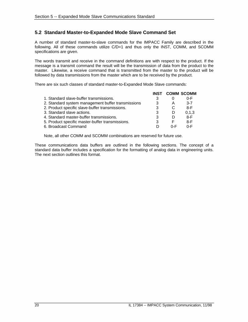
5.2 Standard Master-to-Expanded Mode Slave Command Set
A number of standard master-to-slave commands for the IMPACC Family are described in thefollowing. All of these commands utilize C/D=1 and thus only the INST, COMM, and SCOMMspecifications are given.
The words transmit and receive in the command definitions are with respect to the product. If themessage is a transmit command the result will be the transmission of data from the product to themaster. Likewise, a receive command that is transmitted from the master to the product will befollowed by data transmissions from the master which are to be received by the product.
There are six such classes of standard master-to-Expanded Mode Slave commands:
INST COMM SCOMM 1. Standard slave-buffer transmissions. 3 0 0-F 2. Standard system management buffer transmissions 3 A 3-7 2. Product specific slave-buffer transmissions. 3 C 8-F 3. Standard slave actions. 3 D 0,1,3 4. Standard master-buffer transmissions. 3 D 8-F 5. Product specific master-buffer transmissions. 3 F 8-F 6. Broadcast Command D 0-F 0-F
Note, all other COMM and SCOMM combinations are reserved for future use.
These communications data buffers are outlined in the following sections. The concept of astandard data buffer includes a specification for the formatting of analog data in engineering units.The next section outlines this format.

Section 5 -- Expanded Mode Slave Communications Standard
IL 17384 -- IMPACC System Communications, 11/98 21
5.2.1 IMPACC 24-Bit Floating Point Number Format
The IMPACC family consists of a number of products that send similar analog parameters(currents, voltages, etc.). Each parameter is sent as a single data transmission with the bytesdefined as shown in the following.
BYTE0 low-order byte of 16-bit magnitudeBYTE1 high-order byte of 16-bit magnitudeBYTE2 scale byte
BYTE2 bit definitions.
b7 0 => the value in BYTE0 and BYTE1 is a 16-bit unsigned integer 1 => the value in BYTE0 and BYTE1 is a 16-bit signed integer
b6 0 => data is invalid 1 => data is valid
b5 0 => multiplier as power of 2 1 => multiplier as power of 10
b4-b0 => multiplier's exponent in 5-bit signed integer form.
This allows a magnitude of multiplier to range from
2-16 to 2+15 (b5 = 0)
or 10-16 to 10 +15 (b5 = 1)
Example 1: The following shows two ways to represent 41,300.
BYTE2 | BYTE1 | BYTE0 MSB | | LSB 0 1 1 0 0 0 0 0 | 1 0 1 0 0 0 0 1 | 0 1 0 1 0 1 0 0
BYTE2 | BYTE1 | BYTE0 MSB | | LSB 0 1 1 0 0 0 1 0 | 0 0 0 0 0 0 0 1 | 1 0 0 1 1 1 0 1
Example 2: The following shows the representation of -79.46.
BYTE2 | BYTE1 | BYTE0 MSB | | LSB 1 1 1 1 1 1 1 0 | 1 1 1 0 0 0 0 0 | 1 1 1 1 0 1 1 0

Section 5 -- Expanded Mode Slave Communications Standard
22 IL 17384 -- IMPACC System Communication, 11/98
5.2.2 Standard Expanded Mode Slave-Buffer Transmissions (0 0-F)
INST COMM SCOMM Command Definition3 0 0 Transmit Fast-Status.3 0 1-2 reserved3 0 3 Transmit All Standard Buffers.3 0 4 reserved3 0 5 Transmit Current Buffer.3 0 6 Transmit Line-to-Line Voltage Buffer.3 0 7 Transmit Line-to-Neutral Voltage Buffer.3 0 8 Transmit Power Buffer(1).3 0 9 Transmit Power Buffer(2).3 0 A Transmit Energy Buffer3 0 B Transmit Saved Energy Buffer3 0 C Transmit Saved Reactive Energy Buffer3 0 D-E reserved3 0 F Receive Expanded Transmit Buffer NumberBuffer Number:
N=1 Transmit Temperature BufferN=2 Transmit Demand Currents BufferN=3 Transmit Current BufferN=4 Transmit Line-line Voltage BufferN=5 Transmit Line-neutral Voltage BufferN=6 Transmit Power BufferN=7 Transmit Per-Phase Power BufferN=8 Transmit System Energy BufferN=9 Transmit THD BufferN=10 Transmit Demand Current Buffer &
Peak Demand Avg. Current (w/ time stamp)N=11 Transmit Demand & Peak Demand Currents (w/ time stamp)N=12 Transmit Demand & Peak Demand Power (w/ time stamp)N=13 Transmit Min/Max Current Buffer (w/ time stamp)N=14 Transmit Min/Max L-L Voltage Buffer (w/ time stamp)N=15 Transmit Min/Max L-N Voltage Buffer (w/ time stamp)N=16 Transmit Min/Max PF-Displacement Buffer (w/ time stamp)N=17 Transmit Min/Max PF-Apparent Buffer (w/ time stamp)N=18 Transmit Min/Max Power/Frequency Buffer (w/ time stamp)N=19 Transmit Min/Max Current %THD Buffer (w/ time stamp)N=20 Transmit Min/Max Voltage %THD Buffer (w/ time stamp)N=21 Transmit Crest Factor BufferN=22 Transmit Min/Max per-phase real power (w/ time stamp)N=23 Transmit Min/Max per-phase reactive power (w/ time stamp)N=24 Transmit Min/Max per-phase VA (w/ time stamp)N=25 Transmit Min/Max Currents Buffer (w/o time stamp)N=26 Transmit Demand & Peak Demand Current (w/o time stamp)N=27 Transmit Demand & Peak Power (w/o time stamp)N=28 Transmit Min/Max Voltage Buffer (w/o time stamp)N=29 Transmit Min/Max Power/Frequency/PF Buffer (w/o time stamp)N=30 Transmit Min/Max Current %THD Buffer (w/o time stamp)N=31 Transmit Min/Max Voltage %THD Buffer (w/o time stamp)N=32 Transmit Min/Max Current THD Magnitude Buffer (w/ time stamp)N=33 Transmit Min/Max Voltage THD Magnitude Buffer (w/ time stamp)N=34 Transmit Whole Load Center Energy Buffer
Table 5.1 Standard Slave-Buffer Command Set

Section 5 -- Expanded Mode Slave Communications Standard
IL 17384 -- IMPACC System Communications, 11/98 23
5.2.2.1 Transmit Fast-Status (3 0 0)
This command will cause the product to respond with one data message with the format shownbelow:
BYTE2 | BYTE1 | BYTE0MSB | | LSBS7 S6 S5 S4 S3 S2 S1 S0|P5 P4 P3 P2 P1 P0 V3 V2|V1 V0 D5 D4 D3 D2 D1 D0
where
D5 D4 D3 D2 D1 D0 => Division code. V3 V2 V1 V0 => Communications software version. P5 P4 P3 P2 P1 P0 => Product ID. S3 S2 S1 S0 => Product defined status bits. S7 S6 S5 S4 => Standard status bits.
S7 S6 0 0 Opened, Off or Ready (Normal Inactive) 0 1 Closed, On or Running (Normal Active) 1 0 Tripped (Abnormal Inactive) 1 1 Alarmed (Abnormal Active)
S5 Opened or Off condition set by remote communicationsS4 Powered on since last Fast-Status requestS3 Product specific: For products that support the Time-Stamped Event Data Buffer (3 C
B) command, this bit=1 indicates the product has a time-stampedevent data buffer that has not been released by the INCOM master.(Note, some products reset this bit (i.e. release the buffer) when thebuffer is read (i.e. upon receiving the 3CB command).
S2,S1,S0 Product Specific
The communications software version is not necessarily the same as the product software version.The communications version is incremented each time the product version is changed in an areathat effects the communications response such as the addition to or modification of a product databuffer.

Section 5 -- Expanded Mode Slave Communications Standard
24 IL 17384 -- IMPACC System Communication, 11/98
5.2.2.2 Transmit All Standard Buffers (3 0 3)
The standard buffers are those defined by INST=3, COMM=0, and SCOMM=5 through A. Thosebuffers that are supported are sent in sequence starting with the SCOMM=5 buffer and ending withthe SCOMM=A buffer. The first message from the slave is a data message that outlines which ofthe 16 standard commands are supported. The BYTE2 of the message contains the number ofExpanded Buffers that are supported by the slave.
The format of the first response message is shown below.
BYTE2 | BYTE1 | BYTE0 MSB | | LSB 0 0 Y Y Y Y Y Y | 0 0 0 0 0 CA C9 C8 | C7 C6 C5 C4 C3 C2 C1 C0
where
CX = 1 indicates that INST=3, COMM = 0, and SCOMM =X is supported.
YYYYYY = number of Expanded Buffers which are supported.
Note: All products respond to the with the "Transmit All Buffers" request with the above message. Bits C5-Cf are set to zero if none of the Standard buffers are supported
5.2.2.3 Transmit Current Buffer (3 0 5)
The Current Buffer response consists of four data messages, each containing an IMPACC 24-bitFloating Point Number . Currents are expressed in amperes. The parameters sent are outlinedbelow.
Message number Parameter Units1 phase current IA Amperes2 phase current IB Amperes3 phase current IC Amperes4 current IX (Note) Amperes
Note: Current IX will usually be ground current. For some products, this current may be eitherfourth pole current or neutral current. These latter cases will not have ground current.
5.2.2.4 Transmit Line-to-Line Voltage Buffer (3 0 6)
The Line-to-Line Voltage Buffer response consists of three data messages, each containing anIMPACC 24-bit Floating Point number. Voltage is expressed in volts. The parameters sent areoutlined below.
Message number Parameter Units1 line-to-line voltage VAB Volts2 line-to-line voltage VBC Volts3 line-to-line voltage VCA Volts

Section 5 -- Expanded Mode Slave Communications Standard
IL 17384 -- IMPACC System Communications, 11/98 25
5.2.2.5 Transmit Line-to-Neutral Voltage Buffer (3 0 7)
The Line-to-Neutral Voltage Buffer response consists of three data messages, each containing anIMPACC 24-bit Floating Point number. Voltage is expressed in volts. The parameters sent areoutlined below.
Message number Parameter Units1 line-to-neutral voltage VAN volts2 line-to-neutral voltage VBN volts3 line-to-neutral voltage VCN volts
5.2.2.6 Transmit Power Buffer(1) (3 0 8)
The Power Buffer(1) response consists of three data messages, each containing an IMPACC 24-bit Floating Point number. The parameters sent are outlined below. The first is the system'spresent power value in watts, the second is the power demand and the third is the energy in unitsof watt hours.
Message number Parameter Units1 power watts2 power demand watts3 energy watthours
5.2.2.7 Transmit Power Buffer(2) (3 0 9)
The Power Buffer response consists of three data messages, each containing an IMPACC 24-bitFloating Point number. The parameters sent are outlined below. The first is the system's presentfrequency, the second vars and the third power factor.
Message number Parameter Units1 frequency hertz2 reactive power vars3 power factor
5.2.2.8 Transmit Energy Buffer (3 0 A)
The Energy Buffer response consists of one data message. This data message contains a 24-bitunsigned integer number representing the value for energy in units of Kilowatthours.
The maximum range for energy is 0 - 16,777,215 kWh.
Section 5 -- Expanded Mode Slave Communications Standard
26 IL 17384 -- IMPACC System Communication, 11/98
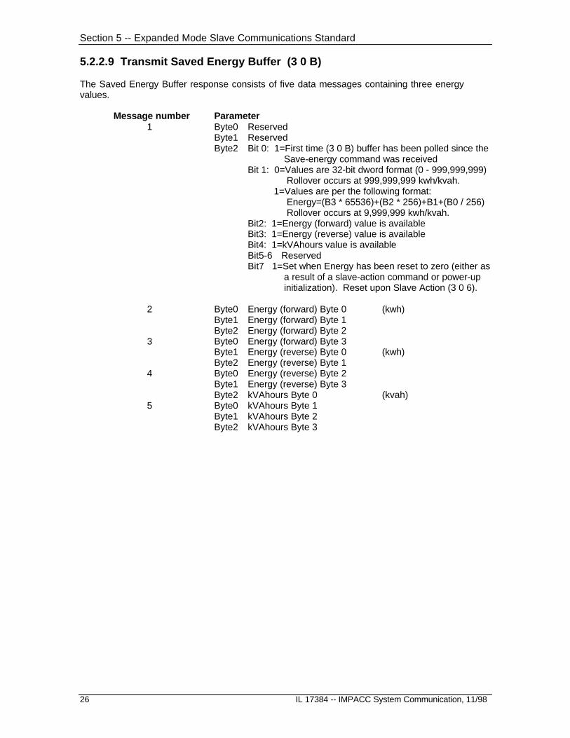
5.2.2.9 Transmit Saved Energy Buffer (3 0 B)
The Saved Energy Buffer response consists of five data messages containing three energyvalues.
Message number Parameter1 Byte0 Reserved
Byte1 ReservedByte2 Bit 0: 1=First time (3 0 B) buffer has been polled since the
Save-energy command was receivedBit 1: 0=Values are 32-bit dword format (0 - 999,999,999)
Rollover occurs at 999,999,999 kwh/kvah. 1=Values are per the following format:
Energy=(B3 * 65536)+(B2 * 256)+B1+(B0 / 256) Rollover occurs at 9,999,999 kwh/kvah.
Bit2: 1=Energy (forward) value is availableBit3: 1=Energy (reverse) value is availableBit4: 1=kVAhours value is availableBit5-6 ReservedBit7 1=Set when Energy has been reset to zero (either as
a result of a slave-action command or power-up initialization). Reset upon Slave Action (3 0 6).
2 Byte0 Energy (forward) Byte 0 (kwh)Byte1 Energy (forward) Byte 1Byte2 Energy (forward) Byte 2
3 Byte0 Energy (forward) Byte 3Byte1 Energy (reverse) Byte 0 (kwh)Byte2 Energy (reverse) Byte 1
4 Byte0 Energy (reverse) Byte 2Byte1 Energy (reverse) Byte 3Byte2 kVAhours Byte 0 (kvah)
5 Byte0 kVAhours Byte 1Byte1 kVAhours Byte 2Byte2 kVAhours Byte 3
Section 5 -- Expanded Mode Slave Communications Standard
IL 17384 -- IMPACC System Communications, 11/98 27
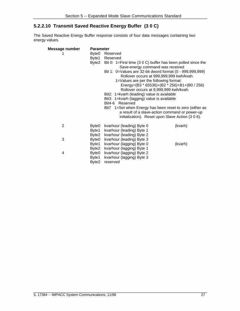
5.2.2.10 Transmit Saved Reactive Energy Buffer (3 0 C)
The Saved Reactive Energy Buffer response consists of four data messages containing twoenergy values.
Message number Parameter1 Byte0 Reserved
Byte1 ReservedByte2 Bit 0: 1=First time (3 0 C) buffer has been polled since the
Save-energy command was receivedBit 1: 0=Values are 32-bit dword format (0 - 999,999,999)
Rollover occurs at 999,999,999 kwh/kvah. 1=Values are per the following format:
Energy=(B3 * 65536)+(B2 * 256)+B1+(B0 / 256) Rollover occurs at 9,999,999 kwh/kvah.
Bit2: 1=kvarh (leading) value is availableBit3: 1=kvarh (lagging) value is availableBit4-6 ReservedBit7 1=Set when Energy has been reset to zero (either as
a result of a slave-action command or power-up initialization). Reset upon Slave Action (3 0 6).
2 Byte0 kvarhour (leading) Byte 0 (kvarh)Byte1 kvarhour (leading) Byte 1Byte2 kvarhour (leading) Byte 2
3 Byte0 kvarhour (leading) Byte 3Byte1 kvarhour (lagging) Byte 0 (kvarh)Byte2 kvarhour (lagging) Byte 1
4 Byte0 kvarhour (lagging) Byte 2Byte1 kvarhour (lagging) Byte 3Byte2 reserved

Section 5 -- Expanded Mode Slave Communications Standard
28 IL 17384 -- IMPACC System Communication, 11/98
5.2.2.11 Transmit Expanded Buffer (3 0 F)
The Expanded Buffer command allows for the use of additional standard responses beyond thosecovered by INST=3, COMM=0, and SCOMM=3 to E. The Expanded Buffer command consists ofthe following communications sequence.
1. Master sends slave Transmit Expanded Buffer Number command.
2. Slave responds with ACK
3. Master sends slave a single data message containing the expanded buffer number.
4. Slave sends the requested buffer as a series of data messages. The first byte BYTE0 ofthe first data message must specify the total number data messages to be sent. Thenumber of data messages is limited to 43.
The expanded buffer number N is sent as a 24 bit binary number.

Section 5 -- Expanded Mode Slave Communications Standard
IL 17384 -- IMPACC System Communications, 11/98 29
5.2.2.9.1 Temperature Buffer (N=1)
This buffer consists of the temperature in degrees centigrade for six motor windings temperatures,two motor bearings temperatures, two load bearings temperature and one ambient temperature.The buffer is sent as five data messages with bytes defined as follows.
message number byte parameter
1 BYTE0 number of additional data messages BYTE1 Winding Temperature 1 BYTE2 Winding Temperature 2
2 BYTE0 Winding Temperature 3 BYTE1 Winding Temperature 4 BYTE2 Winding Temperature 5
3 BYTE0 Winding Temperature 6 BYTE1 Motor Bearing 1 Temperature BYTE2 Motor Bearing 2 Temperature
4 BYTE0 Load Bearing 1 Temperature BYTE1 Load Bearing 2 Temperature BYTE2 Auxiliary Temperature
5 BYTE0 VALIDITY 1 BYTE1 VALIDITY 2 BYTE2
Temperatures are presented as binary numbers, range 0 to 255 degrees centigrade. TheVALIDITY bytes are used to represent the presence of a selected sensor. The VALIDITY bytes aredefined as follows.
VALIDITY 1 = b7 b6 b5 b4 b3 b2 b1 b0 MB2 MB1 WT6 WT5 WT4 WT3 WT2 WT1
VALIDITY 2 = b7 b6 b5 b4 b3 b2 b1 b0 DEV AUX LB2 LB1
If a bit is set its associated temperature is valid. The DEV bit represents a device interface controlbit.

Section 5 -- Expanded Mode Slave Communications Standard
30 IL 17384 -- IMPACC System Communication, 11/98
5.2.2.9.2 Peak Demand Currents(1) Buffer (N=2)
The Peak Demand Currents Buffer response consists of four data messages, each containing anIMPACC 24-bit Floating Point Number . Currents are expressed in amperes. The parameters sentare outlined below.
Message number Parameter Units Format 1 Byte 0 -- No. of additional msgs = 42 Peak demand current phase A amps IMPACC 24-bit float3 Peak demand current phase B amps IMPACC 24-bit float4 Peak demand current phase C amps IMPACC 24-bit float5 Peak demand current phase X amps IMPACC 24-bit float
Note: Peak demand current phase X will usually be ground current. For some products, thiscurrent may be either fourth pole current or neutral current. These latter cases will nothave ground current.
5.2.2.9.3 Currents Buffer (N=3)
Message number Parameter Units Format 1 Byte 0 -- No. of additional msgs = 62 Phase A current amps IMPACC 24-bit float3 Phase B current amps IMPACC 24-bit float4 Phase C current amps IMPACC 24-bit float5 Ground current amps IMPACC 24-bit float6 Neutral current amps IMPACC 24-bit float7 Average phase current amps IMPACC 24-bit float
5.2.2.9.4 Line-to-line Voltage Buffer (N=4)
Message number Parameter Units Format 1 Byte 0 -- No. of additional msgs = 42 Line-to-line voltage VAB volts IMPACC 24-bit float3 Line-to-line voltage VBC volts IMPACC 24-bit float4 Line-to-line voltage VCA volts IMPACC 24-bit float5 Average line-to-line voltage volts IMPACC 24-bit float
5.2.2.9.5 Line-to-Neutral Voltage Buffer (N=5)
Message number Parameter Units Format 1 Byte 0 -- No. of additional msgs = 52 Line-to-neutral voltage VAN volts IMPACC 24-bit float3 Line-to-neutral voltage VBN volts IMPACC 24-bit float4 Line-to-neutral voltage VCN volts IMPACC 24-bit float5 Average line-to-neutral voltage volts IMPACC 24-bit float6 Neutral-to-ground voltage volts IMPACC 24-bit float

Section 5 -- Expanded Mode Slave Communications Standard
IL 17384 -- IMPACC System Communications, 11/98 31
5.2.2.9.6 Power Buffer (N=6)
Message number Parameter Units Format 1 Byte 0 -- No. of additional msgs = 82 real power -- 3-phase watts IMPACC 24-bit float3 reactive power -- 3 phase vars IMPACC 24-bit float4 Voltamperes -- 3 phase VA IMPACC 24-bit float5 PF displacement -- 3 phase IMPACC 24-bit float6 PF apparent -- 3 phase IMPACC 24-bit float7 Frequency Hz IMPACC 24-bit float8 K-Factor IMPACC 24-bit float9 THD Factor IMPACC 24-bit float
5.2.2.9.7 Per-Phase Power Buffer (N=7)
Message number Parameter Units Format 1 Byte 0 -- No. of additional msgs = 152 real power -- phase A watts IMPACC 24-bit float3 real power -- phase B watts IMPACC 24-bit float4 real power -- phase C watts IMPACC 24-bit float5 reactive power -- phase A vars IMPACC 24-bit float6 reactive power -- phase B vars IMPACC 24-bit float7 reactive power -- phase C vars IMPACC 24-bit float8 Voltamperes -- phase A VA IMPACC 24-bit float9 Voltamperes -- phase B VA IMPACC 24-bit float10 Voltamperes -- phase C VA IMPACC 24-bit float11 PF displacement -- phase A IMPACC 24-bit float12 PF displacement -- phase B IMPACC 24-bit float13 PF displacement -- phase C IMPACC 24-bit float14 PF apparent -- phase A IMPACC 24-bit float15 PF apparent -- phase B IMPACC 24-bit float16 PF apparent -- phase C IMPACC 24-bit float

Section 5 -- Expanded Mode Slave Communications Standard
32 IL 17384 -- IMPACC System Communication, 11/98
5.2.2.9.8 System Energy Buffer (N=8)
Message number Parameter Units Format 1 Byte0 No. of additional msgs = 12
Byte1 Engineering Units power of 10 3=K units, 6=M units
Byte2 reserved = 02 Byte0 watthours (fwd) byte0 xxwh 32-bit unsigned integer
Byte1 watthours (fwd) byte1Byte2 watthours (fwd) byte2
3 Byte0 watthours (fwd) byte3Byte1 watthours (rev) byte0 xxwh 32-bit unsigned integerByte2 watthours (rev) byte1
4 Byte0 watthours (rev) byte2Byte1 watthours (rev) byte3Byte2 watthours (net) byte0 xxwh 32-bit signed integer
5 Byte0 watthours (net) byte1Byte1 watthours (net) byte2Byte2 watthours (net) byte3
6 Byte0 varhours (leading) byte0 xxvarh 32-bit unsigned integerByte1 varhours (leading) byte1Byte2 varhours (leading) byte2
7 Byte0 varhours (leading) byte3Byte1 varhours (lagging) byte0 xxvarh 32-bit unsigned integerByte2 varhours (lagging) byte1
8 Byte0 varhours (lagging) byte2Byte1 varhours (lagging) byte3Byte2 varhours (net) byte0 xxvarh 32-bit signed integer
9 Byte0 varhours (net) byte1Byte1 varhours (net) byte2Byte2 varhours (net) byte3
10 Byte0 VAhours byte0 xxvah 32-bit unsigned integerByte1 VAhours byte1Byte2 VAhours byte2
11 Byte0 VAhours byte3Byte1 Time last reset -- Hour (0-23) packed BCDByte2 Time last reset -- Minute (0-59)
12 Byte0 Time last reset -- Second (0-59)Byte1 Date last reset -- Month (1-12)Byte2 Date last reset -- Day (1-31)
13 Byte0 Date last reset -- Year (0-99)Byte1 reservedByte2 reserved
FF Note: All time and dates in buffers N=10, 11, 12, 13, 14, 15, 16, 17, 18,19, 20, 22, 23, and 24 are in the format:
Time Byte0 Hour (0-23) Packed BCDByte1 Minute (0-59) Packed BCDByte2 Second (0-59) Packed BCD
Date Byte0 Month (1-12) Packed BCD Note: Month=0 indicates the timeByte1 Day (1-31) Packed BCD and date are notByte2 Year (0-99) Packed BCD available.
Section 5 -- Expanded Mode Slave Communications Standard
IL 17384 -- IMPACC System Communications, 11/98 33
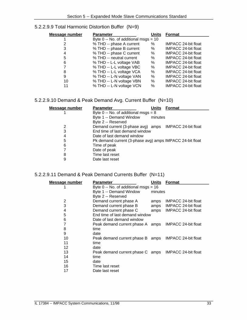
5.2.2.9.9 Total Harmonic Distortion Buffer (N=9)
Message number Parameter Units Format 1 Byte 0 -- No. of additional msgs = 102 % THD -- phase A current % IMPACC 24-bit float3 % THD -- phase B current % IMPACC 24-bit float4 % THD -- phase C current % IMPACC 24-bit float5 % THD -- neutral current % IMPACC 24-bit float6 % THD – L-L voltage VAB % IMPACC 24-bit float7 % THD -- L-L voltage VBC % IMPACC 24-bit float8 % THD -- L-L voltage VCA % IMPACC 24-bit float9 % THD -- L-N voltage VAN % IMPACC 24-bit float10 % THD -- L-N voltage VBN % IMPACC 24-bit float11 % THD -- L-N voltage VCN % IMPACC 24-bit float
5.2.2.9.10 Demand & Peak Demand Avg. Current Buffer (N=10)
Message number Parameter Units Format 1 Byte 0 -- No. of additional msgs = 8
Byte 1 -- Demand Window minutesByte 2 -- Reserved
2 Demand current (3-phase avg) amps IMPACC 24-bit float3 End time of last demand window4 Date of last demand window5 Pk demand current (3-phase avg) amps IMPACC 24-bit float6 Time of peak7 Date of peak8 Time last reset9 Date last reset
5.2.2.9.11 Demand & Peak Demand Currents Buffer (N=11)
Message number Parameter Units Format 1 Byte 0 -- No. of additional msgs = 16
Byte 1 -- Demand Window minutesByte 2 -- Reserved
2 Demand current phase A amps IMPACC 24-bit float3 Demand current phase B amps IMPACC 24-bit float4 Demand current phase C amps IMPACC 24-bit float5 End time of last demand window6 Date of last demand window7 Peak demand current phase A amps IMPACC 24-bit float8 time 9 date10 Peak demand current phase B amps IMPACC 24-bit float11 time12 date13 Peak demand current phase C amps IMPACC 24-bit float14 time15 date16 Time last reset17 Date last reset
Section 5 -- Expanded Mode Slave Communications Standard
34 IL 17384 -- IMPACC System Communication, 11/98
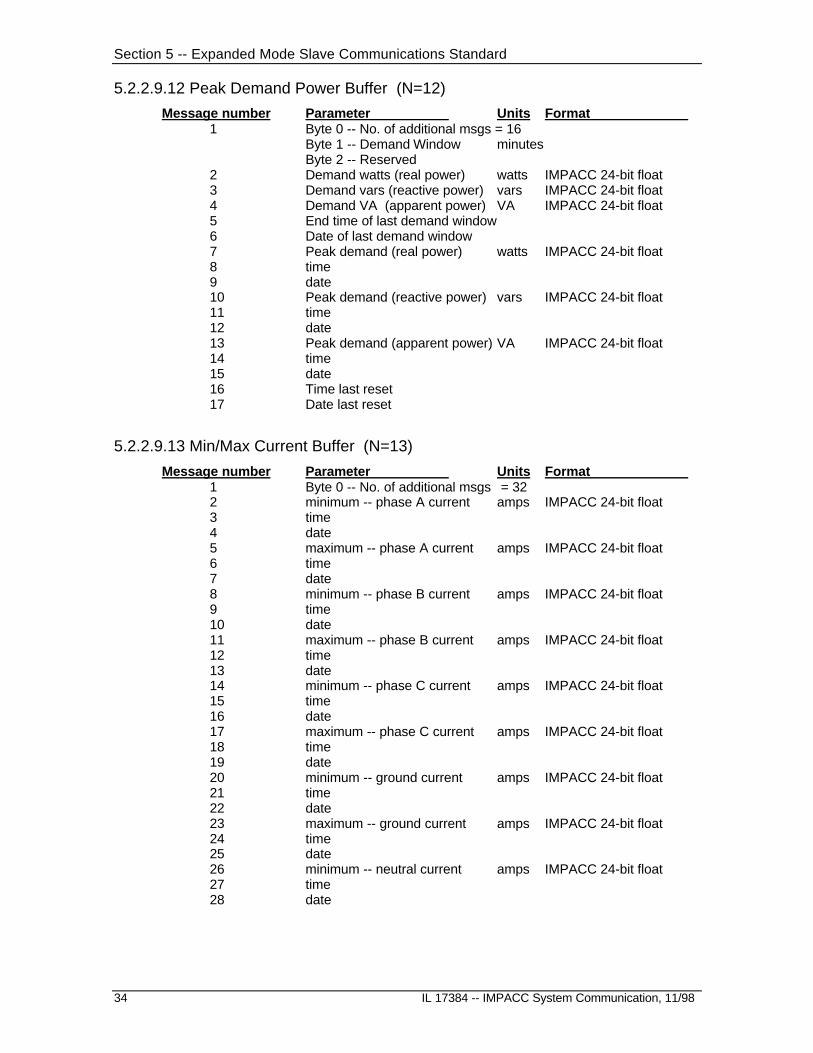
5.2.2.9.12 Peak Demand Power Buffer (N=12)
Message number Parameter Units Format 1 Byte 0 -- No. of additional msgs = 16
Byte 1 -- Demand Window minutesByte 2 -- Reserved
2 Demand watts (real power) watts IMPACC 24-bit float3 Demand vars (reactive power) vars IMPACC 24-bit float4 Demand VA (apparent power) VA IMPACC 24-bit float5 End time of last demand window6 Date of last demand window7 Peak demand (real power) watts IMPACC 24-bit float8 time 9 date10 Peak demand (reactive power) vars IMPACC 24-bit float11 time12 date13 Peak demand (apparent power) VA IMPACC 24-bit float14 time15 date16 Time last reset17 Date last reset
5.2.2.9.13 Min/Max Current Buffer (N=13)
Message number Parameter Units Format 1 Byte 0 -- No. of additional msgs = 322 minimum -- phase A current amps IMPACC 24-bit float3 time 4 date5 maximum -- phase A current amps IMPACC 24-bit float6 time7 date8 minimum -- phase B current amps IMPACC 24-bit float9 time 10 date11 maximum -- phase B current amps IMPACC 24-bit float12 time13 date14 minimum -- phase C current amps IMPACC 24-bit float15 time 16 date17 maximum -- phase C current amps IMPACC 24-bit float18 time19 date20 minimum -- ground current amps IMPACC 24-bit float21 time 22 date23 maximum -- ground current amps IMPACC 24-bit float24 time25 date26 minimum -- neutral current amps IMPACC 24-bit float27 time 28 date
Section 5 -- Expanded Mode Slave Communications Standard
IL 17384 -- IMPACC System Communications, 11/98 35
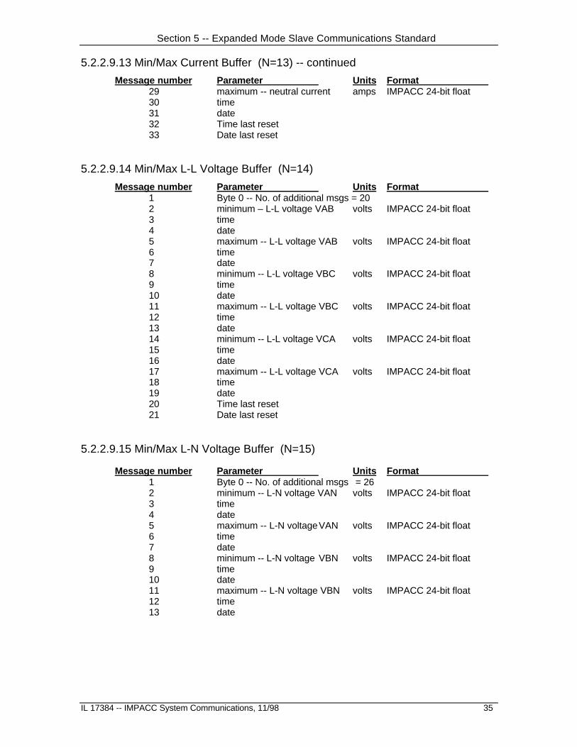
5.2.2.9.13 Min/Max Current Buffer (N=13) -- continued
Message number Parameter Units Format 29 maximum -- neutral current amps IMPACC 24-bit float30 time31 date32 Time last reset33 Date last reset
5.2.2.9.14 Min/Max L-L Voltage Buffer (N=14)
Message number Parameter Units Format 1 Byte 0 -- No. of additional msgs = 202 minimum – L-L voltage VAB volts IMPACC 24-bit float3 time 4 date5 maximum -- L-L voltage VAB volts IMPACC 24-bit float6 time7 date8 minimum -- L-L voltage VBC volts IMPACC 24-bit float9 time 10 date11 maximum -- L-L voltage VBC volts IMPACC 24-bit float12 time13 date14 minimum -- L-L voltage VCA volts IMPACC 24-bit float15 time 16 date17 maximum -- L-L voltage VCA volts IMPACC 24-bit float18 time19 date20 Time last reset21 Date last reset
5.2.2.9.15 Min/Max L-N Voltage Buffer (N=15)
Message number Parameter Units Format 1 Byte 0 -- No. of additional msgs = 262 minimum -- L-N voltage VAN volts IMPACC 24-bit float3 time 4 date5 maximum -- L-N voltageVAN volts IMPACC 24-bit float6 time7 date8 minimum -- L-N voltage VBN volts IMPACC 24-bit float9 time 10 date11 maximum -- L-N voltage VBN volts IMPACC 24-bit float12 time13 date

Section 5 -- Expanded Mode Slave Communications Standard
36 IL 17384 -- IMPACC System Communication, 11/98
5.2.2.9.15 Min/Max L-N Voltage Buffer (N=15) -- continued
Message number Parameter Units Format 14 minimum -- L-N voltage VCN volts IMPACC 24-bit float15 time 16 date17 maximum -- L-N voltageVCN volts IMPACC 24-bit float18 time19 date20 minimum -- neutral-gnd vltg volts IMPACC 24-bit float21 time 22 date23 maximum -- neutral-gnd vltg volts IMPACC 24-bit float24 time25 date26 Time last reset27 Date last reset
5.2.2.9.16 Min/Max PF-Displacement Buffer (N=16)
Message number Parameter Format 1 Byte 0 -- No. of additional msgs = 262 minimum -- phase A PF (disp) IMPACC 24-bit float3 time 4 date5 maximum -- phase A PF (disp) IMPACC 24-bit float6 time7 date8 minimum -- phase B PF (disp) IMPACC 24-bit float9 time 10 date11 maximum -- phase B PF (disp) IMPACC 24-bit float12 time13 date14 minimum -- phase C PF (disp) IMPACC 24-bit float15 time 16 date17 maximum -- phase C PF (disp) IMPACC 24-bit float18 time19 date20 minimum -- system PF (disp) IMPACC 24-bit float21 time 22 date23 maximum -- system PF (disp) IMPACC 24-bit float24 time25 date26 Time last reset27 Date last reset

Section 5 -- Expanded Mode Slave Communications Standard
IL 17384 -- IMPACC System Communications, 11/98 37
5.2.2.9.17 Min/Max PF-Apparent Buffer (N=17)
Message number Parameter Format 1 Byte 0 -- No. of additional msgs = 262 minimum -- phase A PF (apparent) IMPACC 24-bit float3 time 4 date5 maximum -- phase A PF (apparent) IMPACC 24-bit float6 time7 date8 minimum -- phase B PF (apparent) IMPACC 24-bit float9 time 10 date11 maximum -- phase B PF (apparent) IMPACC 24-bit float12 time13 date14 minimum -- phase C PF (apparent) IMPACC 24-bit float15 time 16 date17 maximum -- phase C PF (apparent) IMPACC 24-bit float18 time19 date20 minimum -- system PF (apparent) IMPACC 24-bit float21 time 22 date23 maximum -- system PF (apparent) IMPACC 24-bit float24 time25 date26 Time last reset27 Date last reset
5.2.2.9.18 Min/Max Power/Frequency Buffer (N=18)
Message number Parameter Format 1 Byte 0 -- No. of additional msgs = 262 minimum -- real power IMPACC 24-bit float3 time 4 date5 maximum -- real power IMPACC 24-bit float6 time7 date8 minimum -- reactive power IMPACC 24-bit float9 time 10 date11 maximum -- reactive power IMPACC 24-bit float12 time13 date14 minimum – Volt-amperes IMPACC 24-bit float15 time 16 date17 maximum – Volt-amperes IMPACC 24-bit float18 time19 date
Section 5 -- Expanded Mode Slave Communications Standard
38 IL 17384 -- IMPACC System Communication, 11/98
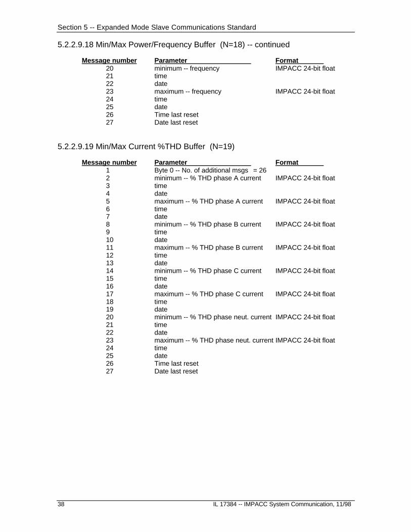
5.2.2.9.18 Min/Max Power/Frequency Buffer (N=18) -- continued
Message number Parameter Format 20 minimum -- frequency IMPACC 24-bit float21 time 22 date23 maximum -- frequency IMPACC 24-bit float24 time25 date26 Time last reset27 Date last reset
5.2.2.9.19 Min/Max Current %THD Buffer (N=19)
Message number Parameter Format 1 Byte 0 -- No. of additional msgs = 262 minimum -- % THD phase A current IMPACC 24-bit float3 time 4 date5 maximum -- % THD phase A current IMPACC 24-bit float6 time7 date8 minimum -- % THD phase B current IMPACC 24-bit float9 time 10 date11 maximum -- % THD phase B current IMPACC 24-bit float12 time13 date14 minimum -- % THD phase C current IMPACC 24-bit float15 time 16 date17 maximum -- % THD phase C current IMPACC 24-bit float18 time19 date20 minimum -- % THD phase neut. current IMPACC 24-bit float21 time 22 date23 maximum -- % THD phase neut. current IMPACC 24-bit float24 time25 date26 Time last reset27 Date last reset

Section 5 -- Expanded Mode Slave Communications Standard
IL 17384 -- IMPACC System Communications, 11/98 39
5.2.2.9.20 Transmit Min/Max Voltage %THD Buffer (N=20)
Message number Parameter Format 1 Byte 0 -- No. of additional msgs = 382 minimum -- % THD L-L voltage VAB IMPACC 24-bit float3 time 4 date5 maximum -- % THD L-L voltage VAB IMPACC 24-bit float6 time7 date8 minimum -- % THD L-L voltage VBC IMPACC 24-bit float9 time 10 date11 maximum -- % THD L-L voltage VBC IMPACC 24-bit float12 time13 date14 minimum -- % THD L-L voltage VCA IMPACC 24-bit float15 time 16 date17 maximum -- % THD L-L voltage VCA IMPACC 24-bit float18 time19 date20 minimum -- % THD L-N voltage VAN IMPACC 24-bit float21 time 22 date23 maximum -- % THD L-N voltage VAN IMPACC 24-bit float24 time25 date26 minimum -- % THD L-N voltage VBN IMPACC 24-bit float27 time 28 date29 maximum -- % THD L-N voltage VBN IMPACC 24-bit float30 time31 date32 minimum -- % THD L-N voltage VCN IMPACC 24-bit float33 time 34 date35 maximum -- % THD L-N voltage VCN IMPACC 24-bit float36 time37 date38 Time last reset39 Date last reset

Section 5 -- Expanded Mode Slave Communications Standard
40 IL 17384 -- IMPACC System Communication, 11/98
5.2.2.9.21 Crest Factor Buffer (N=21)
Message number Parameter Units Format 1 Byte0 Number of additional msgs = 7
Byte1 IA crest factor x 256 -- low byteByte2 IA crest factor x 256 -- high byte
2 Byte0 IB crest factor x 256 -- low byteByte1 IB crest factor x 256 -- high byteByte2 IC crest factor x 256 -- low byte
3 Byte0 IC crest factor x 256 -- high byteByte1 IG crest factor x 256 -- low byteByte2 IG crest factor x 256 -- high byte
4 Byte0 In crest factor x 256 -- low byteByte1 In crest factor x 256 -- high byteByte2 VAN crest factor x 256 -- low byte
5 Byte0 VAN crest factor x 256 -- high byteByte1 VBN crest factor x 256 -- low byteByte2 VBN crest factor x 256 -- high byte
6 Byte0 VCN crest factor x 256 -- low byteByte1 VCN crest factor x 256 -- high byteByte2 VAB crest factor x 256 -- low byte
7 Byte0 VAB crest factor x 256 -- high byteByte1 VBC crest factor x 256 -- low byteByte2 VBC crest factor x 256 -- high byte
8 Byte0 VCA crest factor x 256 -- low byteByte1 VCA crest factor x 256 -- high byteByte2 reserved
5.2.2.9.22 Min/Max Real Power Buffer (N=22)
Message number Parameter Units Format 1 Byte 0 -- No. of additional msgs = 202 minimum -- Real power phase A IMPACC 24-bit float3 time 4 date5 maximum -- Real power phase A IMPACC 24-bit float6 time7 date8 minimum -- Real power phase B IMPACC 24-bit float9 time 10 date11 maximum -- Real power phase B IMPACC 24-bit float12 time13 date14 minimum -- Real power phase C IMPACC 24-bit float15 time 16 date17 maximum -- Real power phase C IMPACC 24-bit float18 time19 date20 Time last reset21 Date last reset

Section 5 -- Expanded Mode Slave Communications Standard
IL 17384 -- IMPACC System Communications, 11/98 41
5.2.2.9.23 Min/Max Reactive Power Buffer (N=23)
Message number Parameter Units Format 1 Byte 0 -- No. of additional msgs = 202 minimum -- Reactive power phase A IMPACC 24-bit float3 time 4 date5 maximum -- Reactive power phase A IMPACC 24-bit float6 time7 date8 minimum -- Reactive power phase B IMPACC 24-bit float9 time 10 date11 maximum -- Reactive power phase B IMPACC 24-bit float12 time13 date14 minimum -- Reactive power phase C IMPACC 24-bit float15 time 16 date17 maximum -- Reactive power phase C IMPACC 24-bit float18 time19 date20 Time last reset21 Date last reset
5.2.2.9.24 Min/Max Voltampere (Apparent Power) Buffer (N=24)
Message number Parameter Units Format 1 Byte 0 -- No. of additional msgs = 202 minimum -- VA phase A IMPACC 24-bit float3 time 4 date5 maximum -- VA phase A IMPACC 24-bit float6 time7 date8 minimum -- VA phase B IMPACC 24-bit float9 time 10 date11 maximum -- VA phase B IMPACC 24-bit float12 time13 date14 minimum -- VA phase C IMPACC 24-bit float15 time 16 date17 maximum -- VA phase C IMPACC 24-bit float18 time19 date20 Time last reset21 Date last reset

Section 5 -- Expanded Mode Slave Communications Standard
42 IL 17384 -- IMPACC System Communication, 11/98
5.2.2.9.25 Min/Max Currents Buffer (N=25)
Message number Parameter Units Format 1 Byte 0 -- No. of additional msgs = 10 2 minimum -- phase A current amps IMPACC 24-bit float 3 maximum -- phase A current amps IMPACC 24-bit float 4 minimum -- phase B current amps IMPACC 24-bit float 5 maximum -- phase B current amps IMPACC 24-bit float 6 minimum -- phase C current amps IMPACC 24-bit float 7 maximum -- phase C current amps IMPACC 24-bit float 8 minimum -- Ground current amps IMPACC 24-bit float 9 maximum -- Ground current amps IMPACC 24-bit float10 minimum -- Neutral current amps IMPACC 24-bit float11 maximum -- Neutral current amps IMPACC 24-bit float
5.2.2.9.26 Demand & Peak Demand Current Buffer (N=26)
Message number Parameter Units Format 1 Byte 0 -- No. of additional msgs = 10
Byte 1 -- 5-minute window update counter (range: 0 - 251)Byte 2 -- Optional -- demand window period (1-60 minutes)
2 Demand current (window) ph A amps IMPACC 24-bit float 3 Demand current (window) ph B amps IMPACC 24-bit float 4 Demand current (window) ph C amps IMPACC 24-bit float 5 Demand ground current (window) amps IMPACC 24-bit float 6 Demand neutral current (window) amps IMPACC 24-bit float 7 Peak demand current phase A amps IMPACC 24-bit float 8 Peak demand current phase B amps IMPACC 24-bit float 9 Peak demand current phase C amps IMPACC 24-bit float10 Peak demand current ground amps IMPACC 24-bit float11 Peak demand current neutral amps IMPACC 24-bit float
5.2.2.9.27 Demand & Peak Demand Power Buffer (N=27)
Message number Parameter Units Format 1 Byte 0 -- No. of additional msgs = 6
Byte 1 -- 5-minute window update counter (range: 0 - 251)Byte 2 -- Demand window period (1-60 minutes)
2 Demand watts (window) watts IMPACC 24-bit float 3 Demand vars (window) vars IMPACC 24-bit float 4 Demand voltamps (window) VA IMPACC 24-bit float 5 Peak demand watts watts IMPACC 24-bit float 6 Peak demand vars vars IMPACC 24-bit float 7 Peak demand voltamperes VA IMPACC 24-bit float
Section 5 -- Expanded Mode Slave Communications Standard
IL 17384 -- IMPACC System Communications, 11/98 43
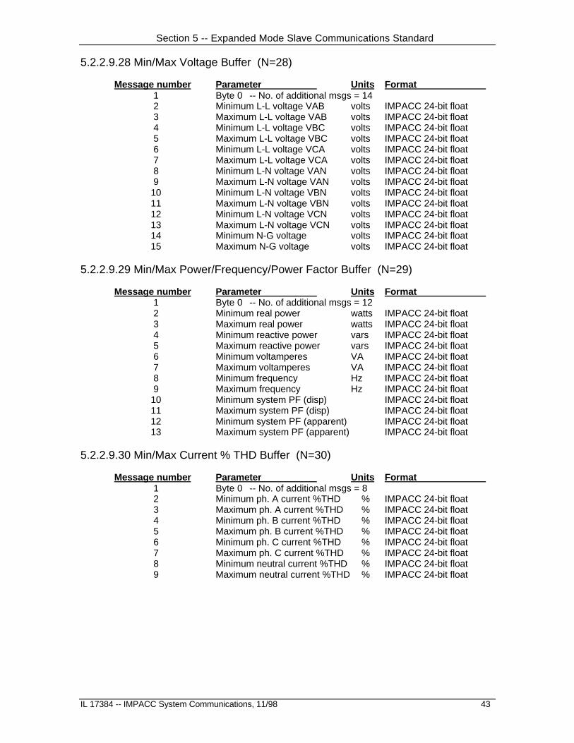
5.2.2.9.28 Min/Max Voltage Buffer (N=28)
Message number Parameter Units Format 1 Byte 0 -- No. of additional msgs = 14 2 Minimum L-L voltage VAB volts IMPACC 24-bit float 3 Maximum L-L voltage VAB volts IMPACC 24-bit float 4 Minimum L-L voltage VBC volts IMPACC 24-bit float 5 Maximum L-L voltage VBC volts IMPACC 24-bit float 6 Minimum L-L voltage VCA volts IMPACC 24-bit float 7 Maximum L-L voltage VCA volts IMPACC 24-bit float 8 Minimum L-N voltage VAN volts IMPACC 24-bit float 9 Maximum L-N voltage VAN volts IMPACC 24-bit float 10 Minimum L-N voltage VBN volts IMPACC 24-bit float 11 Maximum L-N voltage VBN volts IMPACC 24-bit float 12 Minimum L-N voltage VCN volts IMPACC 24-bit float 13 Maximum L-N voltage VCN volts IMPACC 24-bit float 14 Minimum N-G voltage volts IMPACC 24-bit float 15 Maximum N-G voltage volts IMPACC 24-bit float
5.2.2.9.29 Min/Max Power/Frequency/Power Factor Buffer (N=29)
Message number Parameter Units Format 1 Byte 0 -- No. of additional msgs = 12 2 Minimum real power watts IMPACC 24-bit float 3 Maximum real power watts IMPACC 24-bit float 4 Minimum reactive power vars IMPACC 24-bit float 5 Maximum reactive power vars IMPACC 24-bit float 6 Minimum voltamperes VA IMPACC 24-bit float 7 Maximum voltamperes VA IMPACC 24-bit float 8 Minimum frequency Hz IMPACC 24-bit float 9 Maximum frequency Hz IMPACC 24-bit float 10 Minimum system PF (disp) IMPACC 24-bit float 11 Maximum system PF (disp) IMPACC 24-bit float 12 Minimum system PF (apparent) IMPACC 24-bit float 13 Maximum system PF (apparent) IMPACC 24-bit float
5.2.2.9.30 Min/Max Current % THD Buffer (N=30)
Message number Parameter Units Format 1 Byte 0 -- No. of additional msgs = 8 2 Minimum ph. A current %THD % IMPACC 24-bit float 3 Maximum ph. A current %THD % IMPACC 24-bit float 4 Minimum ph. B current %THD % IMPACC 24-bit float 5 Maximum ph. B current %THD % IMPACC 24-bit float 6 Minimum ph. C current %THD % IMPACC 24-bit float 7 Maximum ph. C current %THD % IMPACC 24-bit float 8 Minimum neutral current %THD % IMPACC 24-bit float 9 Maximum neutral current %THD % IMPACC 24-bit float

Section 5 -- Expanded Mode Slave Communications Standard
44 IL 17384 -- IMPACC System Communication, 11/98
5.2.2.9.31 Min/Max Voltage % THD Buffer (N=31)
Message number Parameter Units Format 1 Byte 0 -- No. of additional msgs = 12 2 Minimum L-L voltage VAB %THD % IMPACC 24-bit float 3 Maximum L-L voltage VAB %THD % IMPACC 24-bit float 4 Minimum L-L voltage VBC %THD % IMPACC 24-bit float 5 Maximum L-L voltage VBC %THD % IMPACC 24-bit float 6 Minimum L-L voltage VCA %THD % IMPACC 24-bit float 7 Maximum L-L voltage VCA %THD % IMPACC 24-bit float 8 Minimum L-N voltage VAN %THD % IMPACC 24-bit float 9 Maximum L-N voltage VAN %THD % IMPACC 24-bit float 10 Minimum L-N voltage VBN %THD % IMPACC 24-bit float 11 Maximum L-N voltage VBN %THD % IMPACC 24-bit float 12 Minimum L-N voltage VCN %THD % IMPACC 24-bit float 13 Maximum L-N voltage VCN %THD % IMPACC 24-bit float
5.2.2.9.32 Min/Max Current THD Magnitude Buffer (N=32)
Message number Parameter Format 1 Byte 0 -- No. of additional msgs = 262 minimum ph A current THD magnitude IMPACC 24-bit float3 time 4 date5 maximum ph A current THD magnitude IMPACC 24-bit float6 time7 date8 minimum ph B current THD magnitude IMPACC 24-bit float9 time 10 date11 maximum ph B current THD magnitude IMPACC 24-bit float12 time13 date14 minimum ph C current THD magnitude IMPACC 24-bit float15 time 16 date17 maximum ph C current THD magnitude IMPACC 24-bit float18 time19 date20 minimum neut. current THD magnitude IMPACC 24-bit float21 time 22 date23 maximum neut. current THD magnitude IMPACC 24-bit float24 time25 date26 Time last reset27 Date last reset

Section 5 -- Expanded Mode Slave Communications Standard
IL 17384 -- IMPACC System Communications, 11/98 45
5.2.2.9.33 Transmit Min/Max Voltage THD Magnitude Buffer (N=33)
Message number Parameter Format 1 Byte 0 -- No. of additional msgs = 382 minimum voltage VAB THD magnitude IMPACC 24-bit float3 time 4 date5 maximum voltage VAB THD magnitude IMPACC 24-bit float6 time7 date8 minimum voltage VBC THD magnitude IMPACC 24-bit float9 time 10 date11 maximum voltage VBC THD magnitude IMPACC 24-bit float12 time13 date14 minimum voltage VCA THD magnitude IMPACC 24-bit float15 time 16 date17 maximum voltage VCA THD magnitude IMPACC 24-bit float18 time19 date20 minimum voltage VAN THD magnitude IMPACC 24-bit float21 time 22 date23 maximum voltage VAN THD magnitude IMPACC 24-bit float24 time25 date26 minimum voltage VBN THD magnitude IMPACC 24-bit float27 time 28 date29 maximum voltage VBN THD magnitude IMPACC 24-bit float30 time31 date32 minimum voltage VCN THD magnitude IMPACC 24-bit float33 time 34 date35 maximum voltage VCN THD magnitude IMPACC 24-bit float36 time37 date38 Time last reset39 Date last reset

Section 5 -- Expanded Mode Slave Communications Standard
46 IL 17384 -- IMPACC System Communication, 11/98
5.2.2.9.34 Transmit APC Energy Buffer (N=34)
Message number Parameter Format 1 Byte0 No. of additional msgs = 2
Byte1 Engineering Units signed, power-of-tenByte2 Mantissa Multiplier signed, power-of-two
2 Byte0 Energy Byte0 (LSB)Byte1 Energy Byte1Byte2 Energy Byte2 Unsigned 48-bit in units of
3 Byte0 Energy Byte3 WatthoursByte1 Energy Byte4Byte2 Energy Byte5 (MSB)
Engineering Units = -128 implies that the Energy value is invalid.
Energy = 2 Mantissa multiplier * (48-bit Energy Value) * 10 Engineering Units
5.2.2.9.35 Transmit APC (Whole Load Center) Saved Energy Buffer (N=35)
Message number Parameter Format 1 Byte0 No. of additional msgs = 5
Byte1 Engineering Units signed, power-of-tenByte2 Mantissa Multiplier signed, power-of-two
2 Byte0 Forward Energy Byte0 (LSB)Byte1 Forward Energy Byte1Byte2 Forward Energy Byte2 Unsigned 48-bit in units of
3 Byte0 Forward Energy Byte3 WatthoursByte1 Forward Energy Byte4Byte2 Forward Energy Byte5 (MSB)
4 Byte0 Bit 0: 1=First time this buffer has been polled since the Save-energy command was received
Bit 1: 1=Energy has been reset, cleared by (3 D 0, 3 0 6)Bit2-3: ReservedBit4: 1=Forward energy value is availableBit5: 1=Reverse energy value is availableBit6-7: Reserved
Byte1 Engineering Units signed, power-of-tenByte2 Mantissa Multiplier signed, power-of-two
5 Byte0 Reverse Energy Byte0 (LSB)Byte1 Reverse Energy Byte1Byte2 Reverse Energy Byte2 Unsigned 48-bit in units of
6 Byte0 Reverse Energy Byte3 WatthoursByte1 Reverse Energy Byte4Byte2 Reverse Energy Byte5 (MSB)
Engineering Units = -128 implies that the Energy value is invalid.
Energy = 2 Mantissa multiplier * (48-bit Energy Value) * 10 Engineering Units

Section 5 -- Expanded Mode Slave Communications Standard
IL 17384 -- IMPACC System Communications, 11/98 47
5.2.3 Transmit Product Specific Slave-Buffers (3 C 8-F)
This transmission consists of an INCOM Control message from the master and one or more datamessages returned from the slave. The BYTE0 of the first data message indicates the number ofadditional messages are to be sent.
1. Master sends slave a request for a Product Specific Buffer Transmission.
2. Slave responds with sending one to 44 data messages. The first byte of the first messageindicates the number of additional messages.
INST COMM SCOMM Command Definition 3 C 8 FLAGs Buffer request
3 C 9 SETPOINTs Buffer request 3 C A Defined per product Buffer request 3 C B TIME STAMPED EVENT DATA Buffer request 3 C C Defined per product Buffer request 3 C D Defined per product Buffer request 3 C E Defined per product Buffer request 3 C F Transmit Expanded Buffer request
Table 5.2 Product Specific Slave-Buffer Command Set
5.2.3.1 Transmit FLAGs Buffer (3 C 8)
BYTE0 of the first message from the slave contains the number of additional data messages thatwill follow.
message number byte parameter
1 BYTE0 number of additional data messages BYTE1 FLAG0 (product specific)
BYTE2 FLAG1 (product specific)
2 BYTE0 FLAG2 (product specific) etc.
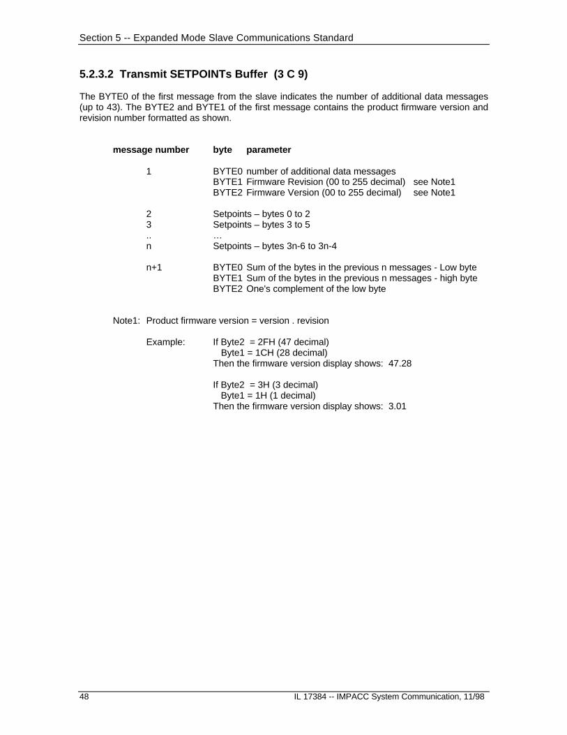
Section 5 -- Expanded Mode Slave Communications Standard
48 IL 17384 -- IMPACC System Communication, 11/98
5.2.3.2 Transmit SETPOINTs Buffer (3 C 9)
The BYTE0 of the first message from the slave indicates the number of additional data messages(up to 43). The BYTE2 and BYTE1 of the first message contains the product firmware version andrevision number formatted as shown.
message number byte parameter
1 BYTE0 number of additional data messagesBYTE1 Firmware Revision (00 to 255 decimal) see Note1BYTE2 Firmware Version (00 to 255 decimal) see Note1
2 Setpoints – bytes 0 to 23 Setpoints – bytes 3 to 5.. …n Setpoints – bytes 3n-6 to 3n-4
n+1 BYTE0 Sum of the bytes in the previous n messages - Low byteBYTE1 Sum of the bytes in the previous n messages - high byteBYTE2 One's complement of the low byte
Note1: Product firmware version = version . revision
Example: If Byte2 = 2FH (47 decimal) Byte1 = 1CH (28 decimal)Then the firmware version display shows: 47.28
If Byte2 = 3H (3 decimal) Byte1 = 1H (1 decimal)Then the firmware version display shows: 3.01
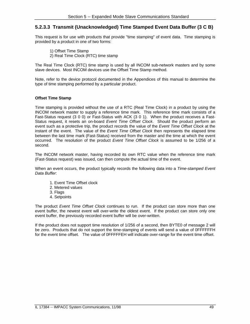
Section 5 -- Expanded Mode Slave Communications Standard
IL 17384 -- IMPACC System Communications, 11/98 49
5.2.3.3 Transmit (Unacknowledged) Time Stamped Event Data Buffer (3 C B)
This request is for use with products that provide "time stamping" of event data. Time stamping isprovided by a product in one of two forms:
1) Offset Time Stamp2) Real Time Clock (RTC) time stamp
The Real Time Clock (RTC) time stamp is used by all INCOM sub-network masters and by someslave devices. Most INCOM devices use the Offset Time Stamp method.
Note, refer to the device protocol documented in the Appendices of this manual to determine thetype of time stamping performed by a particular product.
Offset Time Stamp
Time stamping is provided without the use of a RTC (Real Time Clock) in a product by using theINCOM network master to supply a reference time mark. This reference time mark consists of aFast-Status request (3 0 0) or Fast-Status with ACK (3 0 1). When the product receives a Fast-Status request, it resets an on-board Event Time Offset Clock. Should the product perform anevent such as a protective trip, the product records the value of the Event Time Offset Clock at theinstant of the event. The value of the Event Time Offset Clock then represents the elapsed timebetween the last time mark (Fast-Status) received from the master and the time at which the eventoccurred. The resolution of the product Event Time Offset Clock is assumed to be 1/256 of asecond.
The INCOM network master, having recorded its own RTC value when the reference time mark(Fast-Status request) was issued, can then compute the actual time of the event.
When an event occurs, the product typically records the following data into a Time-stamped EventData Buffer:
1. Event Time Offset clock2. Metered values3. Flags4. Setpoints
The product Event Time Offset Clock continues to run. If the product can store more than oneevent buffer, the newest event will over-write the oldest event. If the product can store only oneevent buffer, the previously recorded event buffer will be over-written.
If the product does not support time resolution of 1/256 of a second, then BYTE0 of message 2 willbe zero. Products that do not support the time-stamping of events will send a value of 0FFFFFFHfor the event time offset. The value of 0FFFFFEH will indicate over-range for the event time offset.

Section 5 -- Expanded Mode Slave Communications Standard
50 IL 17384 -- IMPACC System Communication, 11/98
RTC Time Stamp
Products which have an on-board RTC (Real Time Clock) record the value of the RTC at theinstant an event occurs. In addition, sub-network masters which have an on-board RTC provide acalculated RTC value for the time of the event.
When an event occurs, the product typically records the following data into a Time-stamped EventData Buffer:
1. RTC value at time of event2. Metered values3. Flags4. Setpoints
If the product can store more than one event buffer, the newest event will over-write the oldestevent. If the product can store only one event buffer, the previously recorded event buffer will beover-written.
Receiving TIME STAMPED EVENT DATA Buffers
The network master is made aware of the existence of an un-released Time-stamped Event DataBuffer by a status bit in the response to a Transmit Fast-Status Request (see 5.2.2.1). The networkmaster may subsequently request that the product transmit the un-released Time-stamped EventData (3 C B). When an un-released event data buffer is read by the master, the buffer is retainedat the product. Each time the buffer is requested the product sends the data buffer for the oldestun-released event. For products which can store more than one Time-stamped Event Data Buffer,the oldest un-released event data buffer must be released before the next Time-stamped EventData buffer can be read by the master. The master issues the Receive Slave Action Number (3 D0) command and sends the “Release Time-stamped Event Data Buffer” action number (see 5.2.4.1- System Control) to acknowledge it has read the current buffer and to inform the product toadvance its internal index of event buffers to the next un-released Time-stamped Event DataBuffer. The master may then read the Time-stamped Event Data Buffer for the next event. This isa cyclic procedure in which the event data buffers are read from the oldest to the most recentevent.
If the master sends the Slave-action command to acknowledge a Time-stamped Event Data Bufferwhen in fact there are no un-released Time-stamped Event Data buffers available in the product,the product will respond with the “Product not in a state that allows the requested action” Slave-to-Master command (see 5.1.7). (Note, some older products may respond with a NACK 311).
If no un-released Time-stamped Event Data Buffers are available at the product, the productresponds to Transmit Time-stamped Event Data (3 C B) request with the Buffer Not Yet AvailableSlave-to-Master command.
All Time-stamped Event Data Buffers can be reset (released) by using a Receive Slave ActionNumber (3 D 0) command with the reset Time Stamped Event Data Buffers action message (see5.2.4.1 - Reset).

Section 5 -- Expanded Mode Slave Communications Standard
IL 17384 -- IMPACC System Communications, 11/98 51
5.2.3.3.1 Time-stamped Event Data Buffers Transmitted by Products that usethe Offset Time Stamp.
Message number Byte Parameter 1 BYTE0 number of additional data messages
BYTE1 Time-stamped Event Data Buffer numberBYTE2 number of additional un-released Time-stamped
Event Data Buffers available excluding the buffer currentlybeing read.
2 BYTE0 Trip Time OffsetBYTE1 "BYTE2 "
where Event Time Offset in seconds = 256*BYTE2 + BYTE1.BYTE0/256
Subsequent messages are sent sequentially as though the Master had sent in order the followingrequests
1. Transmit All Standard Buffers (3 0 3)2. (Optional) -- Transmit FLAGS Buffer Request (3 C 8)3. (Optional) -- Transmit SETPOINTs Buffer Request (3 C 9)4. (Optional) -- Transmit Product Specific Buffer(s) (3 C X)5. (Optional) -- Transmit Other Data
Note: Some products do not include all of their standard (3 0 X) buffers in the event data buffer.Such products will indicate in the buffer supported map (3rd message) which standardbuffers are included in the event data buffer. Please refer to the appropriate appendix formore information.

Section 5 -- Expanded Mode Slave Communications Standard
52 IL 17384 -- IMPACC System Communication, 11/98
5.2.3.3.2 Time-stamped Event Data Buffers Transmitted by products that usethe RTC (Real Time Clock) Time Stamp.
Time-Stamped Event Data Buffers received from a product with a RTC (real time clock) will havetwo additional INCOM data messages, and the format of the time offset will be different than if theproduct did not have an RTC. These differences result from the fact that the product calculates thetime and date that the event occurred. Refer to Section 5.2.4.2 (Process Sub-Network Command)for more information on how to communicate to products on sub-networks. Refer to Section 5.2.5.1(Receive Current Date and Time) for information on how to update a product RTC (real time clock).
Message number Byte Parameter 1 BYTE0 number of additional data messages
BYTE1 Time-stamped Event Data Buffer numberBYTE2 number of additional unacknowledged Time-stamped
Event Data Buffers available (pertaining to the deviceaddressed) excluding the buffer currently being read.
2 BYTE0 Total number of events (all devices) currently bufferedBYTE1 1/100 second (0-99) Packed BCDBYTE2 Hour (0-23) Packed BCD
3 BYTE0 Minute (0 - 59) Packed BCDBYTE1 Second (0 - 59) Packed BCDBYTE2 Month (1 - 12) Packed BCD **See Note1 below
4 BYTE0 Day (1 - 31) Packed BCDBYTE1 Year (0 - 99) Packed BCDBYTE2 Buffer Type 0 = Trip Event
1 = Alarm Event80H = No Response Event81H= Transfer Event
Note1: A value of negative 1 (0FFHEX) for the month is used to indicate the Slave device’sclock may not be synchronized with the Master’s clock (ie. that the slave devicehas not received an “Update Time” message from the master). When the “Monthof Trip” is negative 1, the remainder of the Time stamp (day, hour, etc.) is the timethe trip occurred relative to when the slave device was last powered up.
Subsequent messages are sent sequentially as though the Master had sent in order the followingrequests
1. Transmit All Standard Buffers (3 0 3)2. (Optional) -- Transmit FLAGS Buffer Request (3 C 8)3. (Optional) -- Transmit SETPOINTs Buffer Request (3 C 9)4. (Optional) -- Transmit Product Specific Buffer(s) (3 C X)5. (Optional) -- Transmit Other Data
Note2: Some products do not include all of their standard (3 0 X) buffers in the event databuffer. Such products will indicate in the buffer supported map (5th message)which standard buffers are included in the event data buffer. Please refer to theappropriate appendix for more information.

Section 5 -- Expanded Mode Slave Communications Standard
IL 17384 -- IMPACC System Communications, 11/98 53
5.2.3.4 Transmit Expanded Buffer (3 C F)
The Expanded Buffer command allows for the use of additional standard responses beyond thosecovered by INST=3, COMM=C and SCOMM=8 to E. The Expanded Buffer command consists ofthe following communications sequence.
1. master sends slave Transmit Expanded Buffer Number command.
2. slave responds with ACK
3. master sends slave the Expanded Buffer number as single data message.
4. slave sends the requested buffer as a series of data messages. The BYTE0 of the first data message specifies the total number data messages to follow.
The expanded buffer number N is sent as a 24 bit binary number. A minimum of 10ms must beallowed between consecutive data transmissions to insure proper slave reception.

Section 5 -- Expanded Mode Slave Communications Standard
54 IL 17384 -- IMPACC System Communication, 11/98
5.2.4 Standard Expanded Mode Slave Action (3 D 0,1)
There are a number of standardized requests that result in the slave or product performing anaction. These are listed below.
INST COMM SCOMM Command Definition 3 D 0 Receive Requested Slave Action Number3 D 1 Process Sub-Network Command
Table 5.3: Standard Slave Action Command Set
5.2.4.1 Receive Slave Action Number (3 D 0)
The slave action number allows for the passing of open, close, reset etc. commands. The multipletransmission requirement allows for more security as well as flexibility.
1. master sends slave Receive Slave Action Number command.
2. slave responds with ACK
3. master sends slave the action number as single data message.
4. slave performs requested action.
5. slave responds with ACK or NACK
(The NACK is returned if for some reason the requested action can not be performed).
The action number N is sent as a 24 bit binary number.

Section 5 -- Expanded Mode Slave Communications Standard
IL 17384 -- IMPACC System Communications, 11/98 55
Reset
This is used to request one of many reset options.
BYTE2 = 0 indicates Reset applications
BYTE1 BYTE0 Definition 0 1 reset alarm 0 2 reset trip 0 4 reset (peak) demand-watts 0 8 reset energy (kilowatt hours) 0 10H reset device software 0 20H reset time stamped event data buffers 0 40H reset (synchronize) demand watts window 0 80H snapshot command 1 1 reset (peak) demand-currents 1 2 reset operations count (or trigger counters) 1 3 reset run time 1 4 Reset all min/max values 1 5 Un-lock wave-form buffer (clear upload-in-progress ) 1 6 Reset discrete input counters 1 13 Reset min/max Currents 1 14 Reset min/max L-L Voltages 1 15 Reset min/max L-N Voltages 1 16 Reset min/max PF-Apparent 1 17 Reset min/max PF-Displacement 1 18 Reset min/max Power 1 19 Reset min/max Current THD 1 20 Reset min/max Voltage THD 1 22 Reset min/max per-ph. power 1 36 Reset op count, runtime, & override count 1 37 Reset motor data maximum values 1 38 Reset motor trip & alarm counters 2 X Reset Locked-trigger #X (X = Trigger number) 3 1 Reset source 1 available time. 3 2 Reset source 1 connect time. 3 3 Reset source 1 run time. 3 4 Reset source 2 available time. 3 5 Reset source 2 connect time. 3 6 Reset source 2 run time. 4 X Reset tamper flag for sensor #X
Circuit Breaker Open-Close
This request is used to open or close a circuit breaker.
BYTE2 = 1 indicates circuit breaker applicationBYTE1 = 0BYTE0 = Value Description
0 = open request 1 = close request 2 = trip request
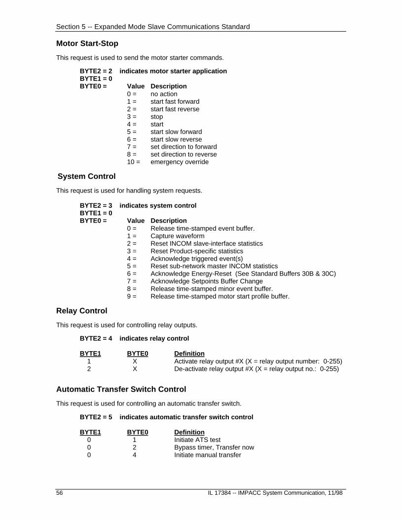
Section 5 -- Expanded Mode Slave Communications Standard
56 IL 17384 -- IMPACC System Communication, 11/98
Motor Start-Stop
This request is used to send the motor starter commands.
BYTE2 = 2 indicates motor starter applicationBYTE1 = 0BYTE0 = Value Description
0 = no action1 = start fast forward2 = start fast reverse3 = stop4 = start5 = start slow forward6 = start slow reverse7 = set direction to forward8 = set direction to reverse10 = emergency override
System Control
This request is used for handling system requests.
BYTE2 = 3 indicates system controlBYTE1 = 0BYTE0 = Value Description
0 = Release time-stamped event buffer.1 = Capture waveform2 = Reset INCOM slave-interface statistics3 = Reset Product-specific statistics4 = Acknowledge triggered event(s)5 = Reset sub-network master INCOM statistics6 = Acknowledge Energy-Reset (See Standard Buffers 30B & 30C)7 = Acknowledge Setpoints Buffer Change8 = Release time-stamped minor event buffer.9 = Release time-stamped motor start profile buffer.
Relay Control
This request is used for controlling relay outputs.
BYTE2 = 4 indicates relay control
BYTE1 BYTE0 Definition 1 X Activate relay output #X (X = relay output number: 0-255) 2 X De-activate relay output #X (X = relay output no.: 0-255)
Automatic Transfer Switch Control
This request is used for controlling an automatic transfer switch.
BYTE2 = 5 indicates automatic transfer switch control
BYTE1 BYTE0 Definition 0 1 Initiate ATS test 0 2 Bypass timer, Transfer now 0 4 Initiate manual transfer
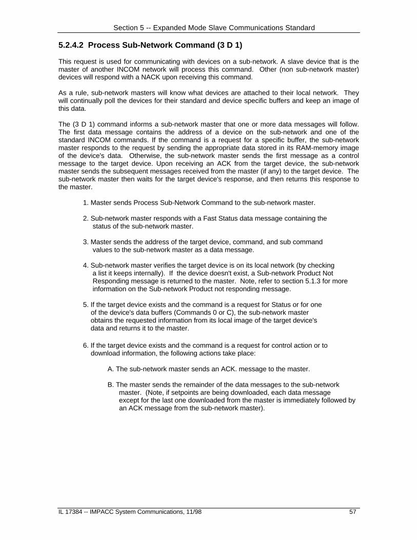
Section 5 -- Expanded Mode Slave Communications Standard
IL 17384 -- IMPACC System Communications, 11/98 57
5.2.4.2 Process Sub-Network Command (3 D 1)
This request is used for communicating with devices on a sub-network. A slave device that is themaster of another INCOM network will process this command. Other (non sub-network master)devices will respond with a NACK upon receiving this command.
As a rule, sub-network masters will know what devices are attached to their local network. Theywill continually poll the devices for their standard and device specific buffers and keep an image ofthis data.
The (3 D 1) command informs a sub-network master that one or more data messages will follow.The first data message contains the address of a device on the sub-network and one of thestandard INCOM commands. If the command is a request for a specific buffer, the sub-networkmaster responds to the request by sending the appropriate data stored in its RAM-memory imageof the device's data. Otherwise, the sub-network master sends the first message as a controlmessage to the target device. Upon receiving an ACK from the target device, the sub-networkmaster sends the subsequent messages received from the master (if any) to the target device. Thesub-network master then waits for the target device's response, and then returns this response tothe master.
1. Master sends Process Sub-Network Command to the sub-network master.
2. Sub-network master responds with a Fast Status data message containing the status of the sub-network master.
3. Master sends the address of the target device, command, and sub command values to the sub-network master as a data message.
4. Sub-network master verifies the target device is on its local network (by checking a list it keeps internally). If the device doesn't exist, a Sub-network Product Not Responding message is returned to the master. Note, refer to section 5.1.3 for more information on the Sub-network Product not responding message.
5. If the target device exists and the command is a request for Status or for one of the device's data buffers (Commands 0 or C), the sub-network master obtains the requested information from its local image of the target device's data and returns it to the master.
6. If the target device exists and the command is a request for control action or to download information, the following actions take place:
A. The sub-network master sends an ACK. message to the master.
B. The master sends the remainder of the data messages to the sub-network master. (Note, if setpoints are being downloaded, each data message except for the last one downloaded from the master is immediately followed by an ACK message from the sub-network master).

Section 5 -- Expanded Mode Slave Communications Standard
58 IL 17384 -- IMPACC System Communication, 11/98
C. The sub-network master sends the control request/download to the target device or in some cases, it may process the control request/download locally. If the control request/download is sent to the target device, the response from the target device (ACK or NACK) is sent to the master. If the command/download is processed locally by the sub-network master, an ACK message is sent to the master if the command is accepted, otherwise a NACK is sent.
FF Note, all INCOM control messages sent by the sub-network master to the mainnetwork master contain the INCOM network address of the sub-networkmaster. ACK, NACK, and any other control messages received by the sub-network master from devices on the sub-network will have their address fieldmodified by the sub-network master before they are forwarded onto the mainnetwork.
The format of the Process Sub-Network Command message is:
C/D = 1INST = 3COMM = DADDRESS = Address of sub-network masterSCOMM = 1
The format of the first data message to be sent by Master following a Process Sub-NetworkCommand message is:
C/D 0 (Note)BYTE0 low nibble INST (of message to be sent )BYTE0 high nibble COMM ( " )BYTE1 low nibble A0 ( " )BYTE1 high nibble A1 ( " )BYTE2 low nibble A2 ( " )BYTE2 high nibble SCOMM ( " )
Note : While C/D = 0 in the received message from the Master, C/D = 1 when passed through tothe Target.
Should the Master send additional data messages after the first, they are passed on to the Targetas data messages with C/D = 0.
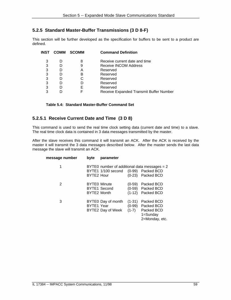
Section 5 -- Expanded Mode Slave Communications Standard
IL 17384 -- IMPACC System Communications, 11/98 59
5.2.5 Standard Master-Buffer Transmissions (3 D 8-F)
This section will be further developed as the specification for buffers to be sent to a product aredefined.
INST COMM SCOMM Command Definition
3 D 8 Receive current date and time3 D 9 Receive INCOM Address3 D A Reserved3 D B Reserved3 D C Reserved3 D D Reserved3 D E Reserved3 D F Receive Expanded Transmit Buffer Number
Table 5.4: Standard Master-Buffer Command Set
5.2.5.1 Receive Current Date and Time (3 D 8)
This command is used to send the real time clock setting data (current date and time) to a slave.The real time clock data is contained in 3 data messages transmitted by the master.
After the slave receives this command it will transmit an ACK. After the ACK is received by themaster it will transmit the 3 data messages described below. After the master sends the last datamessage the slave will transmit an ACK.
message number byte parameter
1 BYTE0 number of additional data messages = 2BYTE1 1/100 second (0-99) Packed BCDBYTE2 Hour (0-23) Packed BCD
2 BYTE0 Minute (0-59) Packed BCDBYTE1 Second (0-59) Packed BCDBYTE2 Month (1-12) Packed BCD
3 BYTE0 Day of month (1-31) Packed BCDBYTE1 Year (0-99) Packed BCDBYTE2 Day of Week (1-7) Packed BCD
1=Sunday2=Monday, etc.
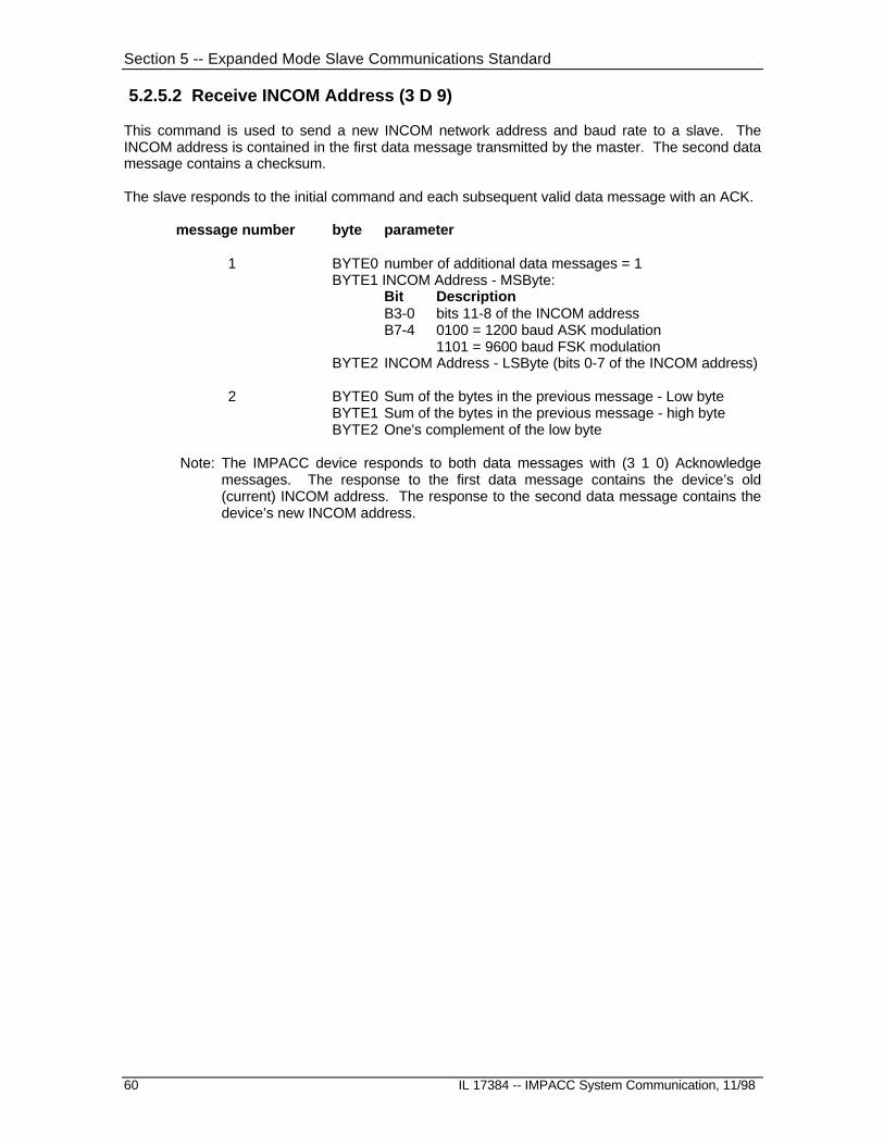
Section 5 -- Expanded Mode Slave Communications Standard
60 IL 17384 -- IMPACC System Communication, 11/98
5.2.5.2 Receive INCOM Address (3 D 9)
This command is used to send a new INCOM network address and baud rate to a slave. TheINCOM address is contained in the first data message transmitted by the master. The second datamessage contains a checksum.
The slave responds to the initial command and each subsequent valid data message with an ACK.
message number byte parameter
1 BYTE0 number of additional data messages = 1BYTE1 INCOM Address - MSByte:
Bit DescriptionB3-0 bits 11-8 of the INCOM addressB7-4 0100 = 1200 baud ASK modulation
1101 = 9600 baud FSK modulationBYTE2 INCOM Address - LSByte (bits 0-7 of the INCOM address)
2 BYTE0 Sum of the bytes in the previous message - Low byteBYTE1 Sum of the bytes in the previous message - high byteBYTE2 One's complement of the low byte
Note: The IMPACC device responds to both data messages with (3 1 0) Acknowledgemessages. The response to the first data message contains the device’s old(current) INCOM address. The response to the second data message contains thedevice’s new INCOM address.

Section 5 -- Expanded Mode Slave Communications Standard
IL 17384 -- IMPACC System Communications, 11/98 61
5.2.6 Product Specific Master-Buffer Transmissions (3 F 8-F)
This transmission consists of a Command message and one or more data messages. BYTE0 ofthe first data message indicates the number of additional messages that will be sent.
1. Master sends slave Product Specific Master-Buffer Transmission message.
2. Slave responds with ACK.
3. Master sends one or more messages. The first byte of the first message indicates thenumber of additional messages.
Note: For most commands, the slave will send an ACK message after each datamessage it receives from the master. For one command (3 F 8), the master sends3 consecutive messages to the slave. In this latter case, the master should inserta 20 millisecond (or greater) delay between consecutive data messages.
4. In all cases, the slave responds after the last downloaded data message with an ACK.
INST COMM SCOMM Command Definition
3 F 8 General download - one ACK at end of download3 F 9 Download setpoints - each message is ACK'd3 F A Product dependent -- each message is ACK’d3 F B Product dependent -- each message is ACK’d3 F C Reserved3 F D Reserved3 F E Reserved3 F F Receive Expanded Receive Buffer
Table 5.5: Product Specific Master-Buffer Command Set
5.2.6.1 General Download (3 F 8)
1. Master sends slave Product Specific Master-Buffer Transmission message.
2. Slave responds with ACK
3. Master sends one to 44 messages. The first byte of the first message indicates the number of additional messages.
4. The slave responds after the last downloaded data message with an ACK.

Section 5 -- Expanded Mode Slave Communications Standard
62 IL 17384 -- IMPACC System Communication, 11/98
5.2.6.2 Download Setpoints (3 F 9)
1. Master sends slave the Download setpoints message (3 F 9).
2. Slave responds with ACK
3. Master sends the first data message. The first byte of this message indicates the number of additional messages.
4. Slave responds with ACK.
5. Master sends the next data message (containing setpoint values).
6. Slave responds with ACK.
7. Steps 5 and 6 are repeated until the setpoint buffer is downloaded.
8. Master sends a data message containing a checksum for the previously downloaded data messages. The checksum is a 16-bit summation of the bytes contained in the previously sent data messages. The format of the checksum message is:
Byte 0 = Sum of the bytes in the previously downloaded messages - Low byteByte 1 = Sum of the bytes in the previously downloaded messages - high byteByte 2 = One's complement of the low byte of the checksum
9. Slave responds with ACK if the checksum is OK and the setpoints are accepted. Slave responds with NACK if the setpoints are not accepted.
Note: If the checksum received by the device is incorrect, or if any of the downloadedsetpoint values are detected as not within an acceptable range, all of thedownloaded setpoints are discarded by the device.

Section 5 -- Expanded Mode Slave Communications Standard
IL 17384 -- IMPACC System Communications, 11/98 63
5.2.7 Broadcast Commands (D X X)
A number of standard master broadcast commands for the IMPACC Family are described in thefollowing. All of these commands utilize C/D=1.
INST COMM SCOMM Command DefinitionD 0 0 Save Energy Buffer RequestD 0 1 Reset Demand WindowD E 2 Capture Waveform (for IQ Analyzers)D E 3 Synchronize RTC (real time clock)D F E Reserved for watchdog timer usageD F F Reserved for hand-held programmers
Table 5.6: Standard Master-Broadcast Command Set
Note: The Synchronize RTC command’s ADDRESS field contains the current secondsand 1/100 of a second. The format is as follows:
ADDRESS = Second & 1/100 second where:Bits 0-6 contains current 1/100 seconds (0-99)Bits 7-11 contain current seconds (0-31)
Note: It is recommended that the Broadcast Synchronize RTC command be transmittedduring the time period from the 15th to the 31st second of the minute.

Section 5 -- Expanded Mode Slave Communications Standard
64 IL 17384 -- IMPACC System Communication, 11/98
5.2.8 Transmit System Management Buffers (3 A 3-7)
This transmission consists of an INCOM Control message from the master and one or more datamessages returned from the slave.
1. Master sends slave a request for a System Management Buffer Transmission.
2. Slave responds with sending one to 43 data messages.
INST COMM SCOMM Command Definition 3 A 3 Transmit PONI configuration
3 A 4 Transmit INCOM slave-interface statistics 3 A 5 Transmit product specific statistics 3 A 6 Transmit sub-network master INCOM statistics 3 A 7 Transmit checksum of previous data packet
5.2.8.1 Transmit PONI configuration buffer (3 A 3)
This buffer is supported by the PONI. It contains two messages containing the PONI’s dip-switchsettings (baud rate and PONI mode), the PONI version, and its program checksum. The format ofthe response is:
Message number Byte Description 1 Byte0 PONI mode and INCOM baud rate
Bit DefinitionB1-0 00=PONI is in Buffered PONI mode
01=PONI is in PONI mode10=PONI is in TSF mode11=LPONI
B2 1=1200 baud, 0=9600 baud INCOMB7-3 Reserved
Byte1 PONI Firmware VersionByte2 PONI Firmware Revision
2 PONI firmware checksum (24-bit unsigned integer)

Section 5 -- Expanded Mode Slave Communications Standard
IL 17384 -- IMPACC System Communications, 11/98 65
5.2.8.2 Transmit INCOM Slave-Interface Statistics buffer (3 A 4)
The INCOM Slave-Interface Statistics buffer consists of 10 INCOM messages that contain thevalues for several INCOM communications-related counters. These counters are maintained byslave devices (including sub-network masters -- which are slave devices on the main network) andprovide a measure of the integrity of the slave device’s INCOM interface to its master. The formatof the response is:
Msg Byte Description Format 1 Byte0 Number of additional data messages = 9
Byte1 Reserved=0Byte2 Reserved=0
2 No. of messages received from master with BCH errors see notes 1, 2, 3 No. of INCOM over-run errors see notes 1, 2 4 No. of messages received (total) from INCOM master see notes 1, 2, 3 5 No. of broadcast messages received from master see notes 1, 2, 4 6 No. of uncompleted slave action requests from master see notes 1, 2, 5 7 No. of invalid commands received from INCOM master see notes 1, 2 8 Reserved=0 9 Reserved=0 10 Reserved=0
Note1: The format of the data in messages 2-7 is as follows:Byte Description Byte0 Bits 0-7 of a 20-bit unsigned valueByte1 Bits 8-15 of a 20-bit unsigned valueByte2 Bits Description
0-3 Bits 16-19 of a 20-bit unsigned value4-6 Reserved=07 Validity: 1=valid, 0=invalid
Note2: These counter values should not roll-over. They should hold their count at theirhighest possible value until a reset command (3 0 2) is sent to the slave device.
Note3: This counter value should include the number of erroneous messages (if any) thatare received (that is, messages with BCH error and invalid command messages).
Note4: This should include all broadcast (D X X) messages received, even those not actedupon by the device.
Note5: This indicates the number of times a (3 D 0) command is received and is notfollowed by a data messages containing a valid request.

Section 5 -- Expanded Mode Slave Communications Standard
66 IL 17384 -- IMPACC System Communication, 11/98
5.2.8.3 Transmit Product Specific Statistics buffer (3 A 5)
The Product Specific Statistics buffer consists of 10 INCOM messages. The definition and formatof the data contained in this buffer is product specific. Please refer to the applicable appendix ofthis document for implementation details for each device. The format of the response is:
Message Byte Description 1 Byte0 Number of additional data messages = 9
Byte1 Reserved=0Byte2 Reserved=0
2 Product specific information 3 Product specific information 4 Product specific information 5 Product specific information 6 Product specific information 7 Product specific information 8 Product specific information 9 Product specific information 10 Product specific information
Note: The Product-specific statistics buffer can be reset via the Slave-action (3 D 0)command (Byte2=3, Byte1=0, Byte0=3). See Section 5.2.4.1 (System Control) foradditional information.

Section 5 -- Expanded Mode Slave Communications Standard
IL 17384 -- IMPACC System Communications, 11/98 67
5.2.8.4 Transmit Sub-Network Master INCOM Statistics buffer (3 A 6)
The Sub-Network Master INCOM Statistics buffer consists of 10 INCOM messages. It containsvalues for several INCOM communications-related counters maintained by the sub-network master,and therefore provides a measure of the communications integrity of the sub-network. TheTransmit Sub-Network Master INCOM statistics request can be sent directly to the sub-networkmaster, or sent as a “pass-thru”, using the (3 D 1) command, to the slave device. The sub-networkmaster will process both types of requests (the pass-thru version is not actually sent to the slavedevice). The sub-network master responds to the direct request with the totals for the sub-network.It responds to pass-thru requests with the values that pertain to the particular device that wasaddressed. The format of the response is:
Msg Byte Description 1 Byte0 Number of additional data messages = 9
Byte1 Reserved=0Byte2 Reserved=0
2 No. of messages received from slave(s) with BCH error See Notes 1,3 3 No. of no-responses (slave communications time-outs) See Notes 1,3 4 No. of invalid fast-status responses from slave(s) See
Notes 1,3 5 No. of un-expected messages received on sub-network See Notes 1,2,3 6 No. of sub-network transmit failures See Notes 1,2,3 7 No. of messages received (total) from slave See Notes 1,38-10 Reserved=0
Note1: The format of the data in messages 2-7 is as follows:Byte Description Byte0 Bits 0-7 of a 20-bit unsigned valueByte1 Bits 8-15 of a 20-bit unsigned valueByte2 Bits Description
0-3 Bits 16-19 of a 20-bit unsigned value4-6 Reserved=07 Validity: 1=valid, 0=invalid
Note2: Values for messages 5 and 6 are maintained for the system, but not for eachdevice.
Note3: These counter values should not roll-over. They should hold their count at theirhighest possible value until a reset command (3 0 5) is sent to the sub-networkmaster.
5.2.8.5 Transmit Checksum of Previous Data Buffer (3 A 7)This transmission consists of an INCOM Control message from the master and one data messagereturned from the slave. The response should contain the slave-computed checksum on the mostrecently sent data buffer. The format of the response message is:
Msg Byte Description 1 Byte0 Sum of the bytes in the previous data buffer transmitted - Low byte
Byte1 Sum of the bytes in the previous data buffer transmitted - high byteByte2 One's complement of the low byte
This command applies to the data buffers that are returned in response to the following INCOMcontrol commands: (3 0 3) through (3 0 F), (3 A 3) through (3 A 6), and the (3 C 8) through (3 D 1).Note, all messages of the previously transmitted data buffer are included in the checksumcalculation (including any messages that may contain another checksum).

Section 5 -- Expanded Mode Slave Communications Standard
68 IL 17384 -- IMPACC System Communication, 11/98
5.3 Standard IMPACC System Functions
5.3.1 Sub-Network Master Demand Synchronization
A Sub-network master device may support up to three methods or modes of operation forsynchronizing the computation of demand-Watts and/or demand-vars. They are:
1) Internal (the sub-network master uses an internal timer or clock to determine thedemand window interval)
2) External pulse (a contact input sensed by the sub-network master is used to determinethe demand windows interval)
3) IMPACC (INCOM communication)These operational modes are mutually exclusive and user select-able. Regardless of the mode, thesub-network master device will perform a demand calculation upon sensing the applicablesynchronization signal.
IMPACC Mode
In the IMPACC mode, the Broadcast Save Energy Buffer request (D 0 0) and the Slave-action SaveEnergy Buffer request (3 D 0 – 0 0 80h) serve as triggers for the sub-network master’s calculationof power demand for each of the energy metering devices on its sub-network. In addition, the sub-network master supports the following protocol to provide energy data for the IMPACC master’slogging of energy. This energy data is sent in the Transmit Saved Energy Buffer (3 0 B) andTransmit Saved Reactive Energy Buffer (3 0 C) buffers which are fabricated by the sub-networkmaster for each energy monitoring device on its sub-network (including all IQ Energy Sentinels --regardless of Comm Version, all Optim 1050s, and all Digitrip 810s and 910s).
Sequence1. Master sends a (D 0 0) Broadcast Save Energy Buffer request to all sub-network masters.
The (D 0 0) command informs all sub-network masters that energy logging and demandcalculations are required by the main network master. Alternately, a (0 0 80h) slave actioncommand (3 D 0) may be sent to individual sub-network master(s) as required.
2. Sub-network master immediately modifies its Flags Buffer (see Flags Buffer Descriptionbelow) as follows:
- sets the “IMPACC synchronization in-process” bit (3 C 8) Message 1 Byte1 Bit 1- clears the “IMPACC synchronization complete” bit (3 C 8) Message 1 Byte1 Bit 0.
Note: A sub-network master can only process one Save Energy Buffer request at a time. Ifthe sub-network master receives a new Save Energy Buffer request while it isprocessing a previous Save Energy Buffer request, it will ignore the new request.Further, if the main network master sends a Slave-action Save Energy Buffer request(3 D 0 – 0 0 80h) while the sub-network master is processing a previous Save EnergyBuffer request, the sub-network master will reply with a Product Not in a State thatallows the Requested Action (3 1 C) NACK.
3. Sub-network master immediately clears the first-time-energy-polled-bit (Msg1 Byte2 Bit0)within each Saved Energy Buffer (3 0 B) and Saved Reactive Energy Buffer(3 0 C) for eachof its slave devices that support energy monitoring.
4. Sub-network master sends the Broadcast Save Energy Buffer request (D 0 0) on its sub-network twice in quick succession.

Section 5 -- Expanded Mode Slave Communications Standard
IL 17384 -- IMPACC System Communications, 11/98 69
5. Sub-network master then reads the Saved Energy Buffers from all sub-network devicesand uses this data to build it own Saved Energy Buffers (3 0 B) and/or (3 0 C) for each sub-network device. If any sub-network device’s energy snapshot has not been saved (e.g.device did not respond to (D 0 0) broadcast) then the sub-network master must issueSlave-action Save Energy Buffer request (3 D 0 – 0 0 80h) to snapshot the energy of thoseparticular sub-network devices. Upon successful reading of a saved energy snapshot froma sub-network device, the sub-network master will modify the appropriate (3 0 B) and/or
(3 0 C) buffers for the applicable sub-network device as follows:- sets (3 0 B) Message 1 Byte2 Bit 0- sets (3 0 C) Message 1 Byte2 Bit 0
If the sub-network device does not indicate reception of the sub-network master’s savedenergy snapshot command, the sub-network master will indicate this via the first-time-energy-polled-bit (Msg1 Byte2 Bit0) within each Saved Energy Buffer (3 0 B) and SavedReactive Energy Buffer(3 0 C) for each such sub-network device.
6. After the Saved Energy (3 0 B) and (3 0 C) buffers for all of the sub-network devices havebeen updated and the sub-network master has completed the demand calculations for allsub-network devices, the logging process is complete and the sub-network master modifiesits Flags Buffer as follows:
- clears the “IMPACC synchronization in-process” bit (3 C 8) Message 1 Byte1 Bit 1- sets the “IMPACC synchronization complete” bit (3 C 8) Message 1 Byte1 Bit 0.
7. Master then requests the Saved Energy (3 0 B) and/or (3 0 C) buffer(s) for each sub-network device utilizing the pass-through (3 D 0) command, and performs its appropriatedata logging.
8. Upon receiving the first request for any sub-network device’s Saved Energy buffer, (afterstep 6), the sub-network master modifies its Flags Buffer as follows:
- clears the “IMPACC synchronization complete” bit (3 C 8) Message 1 Byte1 Bit 0.
Additionally, as each Saved Energy (3 0 B) and/or (3 0 C) buffer for a sub-network device isrequested by the main network master, the sub-network master will modify that (3 0 B)and/or (3 0 C) buffer as follows:
- clears (3 0 B) Message 1 Byte2 Bit 0- clears (3 0 C) Message 1 Byte2 Bit 0
Note: The IMPACC main network master can verify that each sub-network master has received thesynchronization trigger (Broadcast Save Energy Buffer request or slave action command) bychecking the sub-network master Flags Buffer as follows:- “IMPACC synchronization in-process” bit (3 C 8) Message 1 Byte1 Bit 1 is set,
OR- “IMPACC synchronization complete” bit (3 C 8) Message 1 Byte1 Bit 0 is set.
Note: The Flags Buffer (3 C 8) Message 1 Byte1 Bit 2 is used to indicate that the sub-networkmaster is configured and ready to respond to the IMPACC mode of synchronization trigger:
- “IMPACC synchronization ready” bit (3 C 8) Message 1 Byte1 Bit 2 is set
All re-tries of energy snapshots for sub-network devices are handled by the sub-network master.The sub-network master shall send (3 1 C) (Product Not in a State that Allows the RequestedAction) NACK to the main network master if the main network master attempts to pass through aslave action command to a sub-network device request a save energy (3 D 0, 0 0 80h). The sub-network master should take no longer than 10 seconds to complete the energy logging anddemand calculations in the IMPACC mode of synchronization trigger.

Section 5 -- Expanded Mode Slave Communications Standard
70 IL 17384 -- IMPACC System Communication, 11/98
Sub-network Master Flags Buffer Description (3 C 8)
Message Byte Description 1 Byte0 Number of additional data messages = 1 Byte1 Demand synchronization status
Bit Description0 IMPACC synchronization complete (1 = complete)1 IMPACC synchronization in-process (1 = in-process)2 IMPACC synchronization ready (1 = ready)7-3 reserved = 0
Byte2 Synch Type (type of demand synchronization) setpoint
2 Reserved = 0
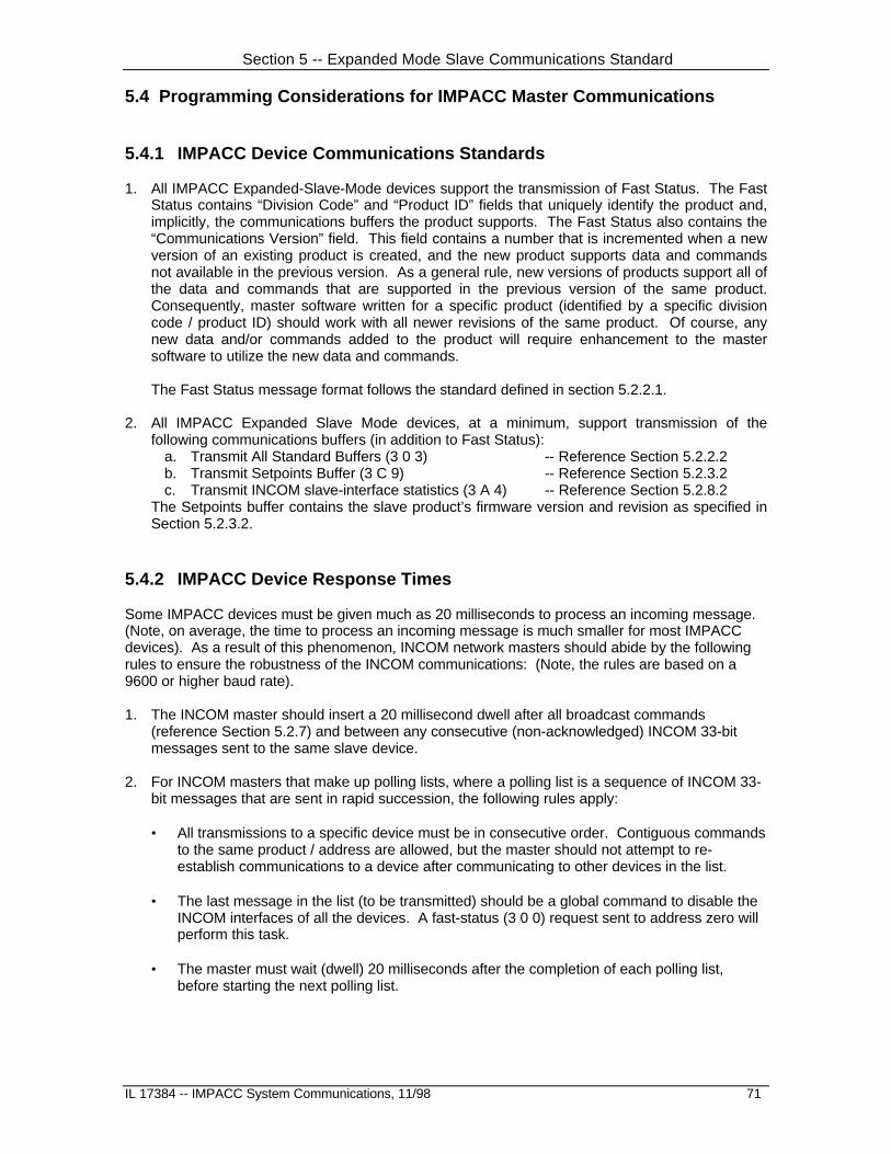
Section 5 -- Expanded Mode Slave Communications Standard
IL 17384 -- IMPACC System Communications, 11/98 71
5.4 Programming Considerations for IMPACC Master Communications
5.4.1 IMPACC Device Communications Standards
1. All IMPACC Expanded-Slave-Mode devices support the transmission of Fast Status. The FastStatus contains “Division Code” and “Product ID” fields that uniquely identify the product and,implicitly, the communications buffers the product supports. The Fast Status also contains the“Communications Version” field. This field contains a number that is incremented when a newversion of an existing product is created, and the new product supports data and commandsnot available in the previous version. As a general rule, new versions of products support all ofthe data and commands that are supported in the previous version of the same product.Consequently, master software written for a specific product (identified by a specific divisioncode / product ID) should work with all newer revisions of the same product. Of course, anynew data and/or commands added to the product will require enhancement to the mastersoftware to utilize the new data and commands.
The Fast Status message format follows the standard defined in section 5.2.2.1.
2. All IMPACC Expanded Slave Mode devices, at a minimum, support transmission of thefollowing communications buffers (in addition to Fast Status):
a. Transmit All Standard Buffers (3 0 3) -- Reference Section 5.2.2.2b. Transmit Setpoints Buffer (3 C 9) -- Reference Section 5.2.3.2c. Transmit INCOM slave-interface statistics (3 A 4) -- Reference Section 5.2.8.2
The Setpoints buffer contains the slave product’s firmware version and revision as specified inSection 5.2.3.2.
5.4.2 IMPACC Device Response Times
Some IMPACC devices must be given much as 20 milliseconds to process an incoming message.(Note, on average, the time to process an incoming message is much smaller for most IMPACCdevices). As a result of this phenomenon, INCOM network masters should abide by the followingrules to ensure the robustness of the INCOM communications: (Note, the rules are based on a9600 or higher baud rate).
1. The INCOM master should insert a 20 millisecond dwell after all broadcast commands(reference Section 5.2.7) and between any consecutive (non-acknowledged) INCOM 33-bitmessages sent to the same slave device.
2. For INCOM masters that make up polling lists, where a polling list is a sequence of INCOM 33-bit messages that are sent in rapid succession, the following rules apply:
• All transmissions to a specific device must be in consecutive order. Contiguous commandsto the same product / address are allowed, but the master should not attempt to re-establish communications to a device after communicating to other devices in the list.
• The last message in the list (to be transmitted) should be a global command to disable theINCOM interfaces of all the devices. A fast-status (3 0 0) request sent to address zero willperform this task.
• The master must wait (dwell) 20 milliseconds after the completion of each polling list,before starting the next polling list.

Section 5 -- Expanded Mode Slave Communications Standard
72 IL 17384 -- IMPACC System Communication, 11/98
This page intentionally left blank.

Section 6
CONI-PC Interface
IL 17384 -- IMPACC System Communications, 11/98 73
6.0 OVERVIEW
The CONI-III may be configured via a dip-switch SW4-1 to operate in one of two possible modes.In the CONI-1a compatibility mode (or mode 1), the CONI-III operates like a CONI-1a. In thismode, the CONI can queue a single transmission message and can buffer multiple receivemessages (up to 1024 receive messages). In mode 2, the CONI-III can queue multipletransmission messages and can buffer the messages it receives in response to thosetransmissions. The CONI-III can buffer a maximum of 256 out-going (TX) messages and 1024 in-coming (RX) messages.
In both modes of operation all data and control information from the PC’s processor is passed tothe CONI-III through I/O registers located on the CONI-III card. The CONI-III does not respond toprocessor memory commands.
6.1 Register Definitions
The CONI-III utilizes twelve I/O port addresses for the passing of control and data information. Thetwelve addresses are consecutive. The starting address is user-selective via six dip switches onthe CONI-III card. Each I/O port provides access to an 8-bit register. Six of the I/O port registersare read-only, three are write-only, and three can be read and written. The purpose for each I/Oport is summarized below:
Location Read/Write Purpose xx0 - xx3 Write Used to output 33-bit INCOM messages to the CONI-III
for subsequent transmission on the INCOM network.xx4 - xx7 Read Used to input 33-bit INCOM messages received
by the CONI-III from the INCOM network.xx8 Write Used to control the transfer of information to and
from the CONI-III.xx8-xx9 Read Used to monitor the status of the CONI-III.xx9 Write Used to set the amount of time the CONI-III will wait
between last received message and the next transmitmessage when transmitting a sequence in mode 2.
xxA Write Used to set the amount of time the CONI-IIIshould wait for responses on the INCOM network.
xxA Read Resets the CONI-IIIxxB Read Used to monitor the status and version of the CONI-III
Note: xx is user-selective via dip switches SW1-1 through SW1-6 on the CONI-III. Itsrange is 00 to 3FHEX. Read-registers xx9 and xxB, and write-register xxA are usedfor mode 2 only. The remaining registers are used for both operational modes.

Section 6 – CONI-PC Interface
74 IL 17384 -- IMPACC System Communication, 11/98
Tx Buffer: xx0HEX - xx3HEX (Write)
The Transmit Buffer consists of four byte-wide write-only registers accessed at I/O addressesxx0HEX through xx3HEX A message to be transmitted is loaded into these I/O locations by the PC’sprocessor. The PC’s processor should write to these registers only when a message is not in theprocess of being transmitted (mode 1) or in the process of being queued (mode 2) as indicated bythe contents of the status register. The registers may be loaded in any order. The format of theTransmit Buffer shown below is for a message with the Control/Data Bit (b2) set to 1. Fielddefinitions change for messages with the Control/Data bit (b2) set to 0, but the bit mapping isidentical.
I/O Port xx0 -- Write Bit 7 Bit 0
C/D U # Receive Messages Expected
| | | | | Mode1: Unused | | Mode2: Number of receive messages to expect in response to this | | transmission. Valid range: 0 - 62 | Unused | Control/Data Bit
I/O Port xx1 -- Write Bit 7 Bit 0
INCOM Command INCOM Instruction
I/O Port xx2 -- Write Bit 7 Bit 0
INCOM Address Field -- Bits 7-0
I/O Port xx3 -- Write Bit 7 Bit 0
INCOM Sub-Command INCOM Address Bits 11-8

Section 6 – CONI-PC Interface
IL 17384 -- IMPACC System Communications, 11/98 75
Rx Buffer: xx4HEX - xx7HEX (Read)
The Receive Buffer consists of four byte-wide read-only registers accessed at I/O addresses xx4HEX
- xx7HEX. All messages received by the CONI-III from the INCOM network are passed to the PCthrough this four byte buffer. The CONI-III will write into the Receive Buffer only when the RxControl Bit in the Status Register is set (SR:1=1). The PC’s processor may read the Receive Bufferin any order after the Rx Control Bit has been reset by the CONI (SR:1=0). After the message hasbeen read by the PC’s processor, it should set the Rx Control Bit by writing the AcknowledgeReceive bit in the Control Register (CR:1=1).
Note: During mode 1 operation, control of the Receive Buffer should be quickly returned to theCONI-III, since only one additional message can be buffered by the INCOM integratedcircuit. During mode 2 operation, the CONI-III buffers up to 1024 receive messages,and timing is not as critical.
I/O Port xx4 -- Read Bit 7 Bit 0
C/D BCH RX Message Number
| | | | | Mode1: Bit 5 = 1, Bits 0-4 are not used | | Mode2: Receive message number (1 to 62) | | Message number = 0 indicates an un-solicited message. | | Message number = 63 indicates a time-out (missing response). | | | BCH error status (1=BCH error, 0=No BCH error) | Control/Data Bit (1=Control message, 0=Data message)
I/O Port xx5 -- Read Bit 7 Bit 0
BYTE0 -- (bits 3-10 of the INCOM message)
I/O Port xx6 -- Read Bit 7 Bit 0
BYTE1 -- (bits 11-18 of the INCOM message)
I/O Port xx7-- Read Bit 7 Bit 0
BYTE2-- (bits 19-26 of the INCOM message)

Section 6 – CONI-PC Interface
76 IL 17384 -- IMPACC System Communication, 11/98
Control Register: xx8HEX (Write)
The Control Register (CR) is used by the PC’s processor to control the CONI-III interface. Theformat of this register is as follows.
I/O Port xx8 -- Write (Mode 1) Bit 7 Bit 0
Baud rate Not used Rx Tx
| | | Initiate Transmit | Acknowledge Receive
I/O Port xx8 -- Write (Mode 2) Bit 7 Bit 0
Baud rateAux
IntrptTxRxIntrpt
Net-work QTx Rx Tx
| | | | | | | | | | | Queue Transmit Message | | | | | and Initiate Transmit Sequence | | | | |
| | | | Acknowledge Receive | | | | | | | Queue Transmit Message | | | | | Network Select (0=Baseband, 1=Carrier) | | | Transmit/Receive Interrupt Enable (1=enable, 0=disable) | Auxiliary Contact Input Interrupt Enable (1=enable, 0=disable)
The definition of bits in this register has been designed so that independent operation of the variousfunctions on the CONI-III can share this common Control Register. Zero fields have been definedto have no effect on their associated control function. For example, initiating the transmitter(SR=01HEX) will not affect operation of the receiver or change the baud rate.
Bit O: Initiate Transmit
Mode 1: When the Control Register is written with a 1 in bit 0 (CR:0=1), the contents of theTransmit Buffer will be transmitted. Once a message transmission is initiated, additionalwrites to bit 0 are ignored until the CONI-III completes the transmission. Writing a 0 in bit0 of the Control Register has no effect.
Mode 2: When the Control Register is written with a 1 in bit 0 (CR:0=1), the CONI-III copies thecontents of the Tx Buffer into its internal transmit-message queue. Then the CONI-IIItransmits the first queued message. It waits for any expected receive messages. Afterreceiving the expected number of messages, or after a communications time-out, theCONI-III sends the second queued message. This process continues until all queuedmessages are transmitted and expected response messages are received by the CONI-III. Once the Initiate Transmit bit is set by the PC processor, the CONI-III ignoresadditional writes of 1 in bit 0 until the operation is complete. Writing a 0 in bit 0 of theControl Register has no effect.

Section 6 – CONI-PC Interface
IL 17384 -- IMPACC System Communications, 11/98 77
Bit 1: Acknowledge Receive
The Control Register (CR) should be written with bit 1 set (CR:1-1) whenever a receive messagehas been processed and the Receive Buffer is available to the CONI. Writing a zero to bit 1 willhave no effect.
Note, the above definition for Bit1 applies to both modes of the CONI-III.
Bit 2: Queue Transmit Message
Mode 1: Not used. Writing either a zero or a one to bit 2 will have no effect.
Mode 2: This bit is used by the PC processor to queue TX messages on to the CONI-III for amultiple-transmission sequence. Specifically, when the Control Register is written with a1 in bit 2 (CR2=1), the CONI-III copies the contents of the TX Buffer into its internalmessage queue. Writing a zero to bit 2 will have no effect.
Note: The Queue Transmit Message bit (Bit 2) can be used to queue a maximum of 255transmit messages on to the CONI-III. The last transmit-message of a multipletransmit-message sequence must be queued by using Bit 0 (the Queue TransmitMessage and Initiate Transmit Sequence bit).
Bit 7 of Port xx0 and Ports xx1-xx3 (Tx Buffer) must be pre-loaded with themessage to be transmitted. Bits 0 - 5 of TX Buffer Port xx0 must be pre-loadedwith the number of RX (receive) messages the CONI-III is to expect as the resultof the transmission. The CONI-III’s receive-message queue can hold a maximumof 1024 RX messages.
Bit 3: Network
Mode 1: Not used. Writing either a zero or a one to bit 3 will have no effect.
Mode 2: This bit selects the transceiver to be used. It is read and acted upon when Transmit isinitiated -- see Bit 0 “Initiate Transmit”. A zero (CR:3=0) selects baseband while a one(CR:3=1) selects INCOM carrier.
Bit 4: Transmit/Receive Interrupt Enable
Mode 1: Not used. Writing either a zero or a one to bit 4 will have no effect.
Mode 2: This bit enables the CONI-III transmit/receive interrupt. When it is set (CR:4=1), theCONI-III issues a PC hardware interrupt whenever it sets either bit 2 or bit 3 of the StatusRegister (SR:2=1 Rx Queue Empty/Tx Sequence Complete, or SR:3=1 Rx MessagePlaced in Rx Buffer). When it is not set (CR:4=0), the CONI-III will not issue PCinterrupts when it sets Status Register bits 2 and 3. In this latter mode of operation, thePC processor must periodically poll the CONI-III status register to determine when theCONI-III has completed a transmit or receive action.
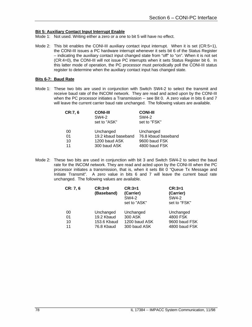
Section 6 – CONI-PC Interface
78 IL 17384 -- IMPACC System Communication, 11/98
Bit 5: Auxiliary Contact Input Interrupt EnableMode 1: Not used. Writing either a zero or a one to bit 5 will have no effect.
Mode 2: This bit enables the CONI-III auxiliary contact input interrupt. When it is set (CR:5=1),the CONI-III issues a PC hardware interrupt whenever it sets bit 6 of the Status Register– indicating the auxiliary contact input changed state from “off” to “on”. When it is not set(CR:4=0), the CONI-III will not issue PC interrupts when it sets Status Register bit 6. Inthis latter mode of operation, the PC processor must periodically poll the CONI-III statusregister to determine when the auxiliary contact input has changed state.
Bits 6-7: Baud Rate
Mode 1: These two bits are used in conjunction with Switch SW4-2 to select the transmit andreceive baud rate of the INCOM network. They are read and acted upon by the CONI-IIIwhen the PC processor initiates a Transmission -- see Bit 0. A zero value in bits 6 and 7will leave the current carrier baud rate unchanged. The following values are available.
CR:7, 6 CONI-III CONI-IIISW4-2 SW4-2set to "ASK" set to "FSK"
00 Unchanged Unchanged 01 19.2 kbaud baseband 76.8 kbaud baseband 10 1200 baud ASK 9600 baud FSK 11 300 baud ASK 4800 baud FSK
Mode 2: These two bits are used in conjunction with bit 3 and Switch SW4-2 to select the baudrate for the INCOM network. They are read and acted upon by the CONI-III when the PCprocessor initiates a transmission, that is, when it sets Bit 0 “Queue Tx Message andInitiate Transmit”. A zero value in bits 6 and 7 will leave the current baud rateunchanged. The following values are available.
CR: 7, 6 CR:3=0 CR:3=1 CR:3=1(Baseband) (Carrier) (Carrier)
SW4-2 SW4-2set to "ASK" set to "FSK"
00 Unchanged Unchanged Unchanged 01 19.2 Kbaud 300 ASK 4800 FSK 10 153.6 Kbaud 1200 baud ASK 9600 baud FSK 11 76.8 Kbaud 300 baud ASK 4800 baud FSK

Section 6 – CONI-PC Interface
IL 17384 -- IMPACC System Communications, 11/98 79
Status Register 1: xx8HEX (Read)
The Status Register (SR) is used by the CONI-III to inform the PC processor the state of the CONI-III card. The contents of this register are read from I/O location xx8h. The format of this register isas follows:
I/O Port xx8 -- Read Bit 7 Bit 0
BusySW4-2/Sync
Mode1: baudMode2: 00 IRr IRt Rx Tx
| | | | | | | Tx Buffer Not Available | | |
| | Rx Buffer Not Available | | | Tx Buffer Unloaded / Rx Queue Empty | Tx Sequence Complete | Rx Message Placed in Rx Buffer
Bit O: Tx Buffer Not Available
This status bit indicates the availability of the Transmit Buffer to the PC processor.
Mode 1: A one (SR:0=1) indicates that the CONI-III is transferring the contents of the TransmitBuffer to the INCOM for transmission on the network. During this time the PC’s processorshould not write to the Transmit Buffer registers. A zero (SR:0=0) indicates that theTransmit Buffer is available to the PC’s processor. After reset, SR:0=0.
Mode 2: A one (SR:0=1) indicates that the CONI-III is transferring the contents of the TransmitBuffer to the CONI-III’s internal message queue. During this time, the PC processorshould not write to the Transmit Buffer (I/O ports xx0-xx3). A zero (SR:0=0) indicates thatthe Transmit Buffer is available to the PC processor. After reset, SR:0=0.
Bit 1: Rx Buffer Not Available
This status bit indicates the availability of the Receive Buffer to the PC processor. A one (SR:1=1)indicates that the Receive Buffer is not available. Reading the Receive Buffer during this time willproduce meaningless data. A zero (SR:1=0) indicates that the buffer contains a valid message andthe PC processor may safely read the contents. After reset, and after the PC Processor sets theAcknowledge Receive Bit (CR:1=1), SR:1=1.
Bit 2: Tx Buffer Unloaded / Rx Queue Empty (Tx Sequence Complete)
Mode 1: This status bit indicates the completion of the last transmission request. This bit will beset (SR:2=1) after the Transmit Buffer has been loaded into the INCOM integrated circuitand transmission is initiated. It will be set at the same time the optional interrupt requestis set. This bit will be cleared (SR:2=0) after the status read operation. Note that theactual message transmission will still be in progress at the time the Transmitter InterruptRequest is set.
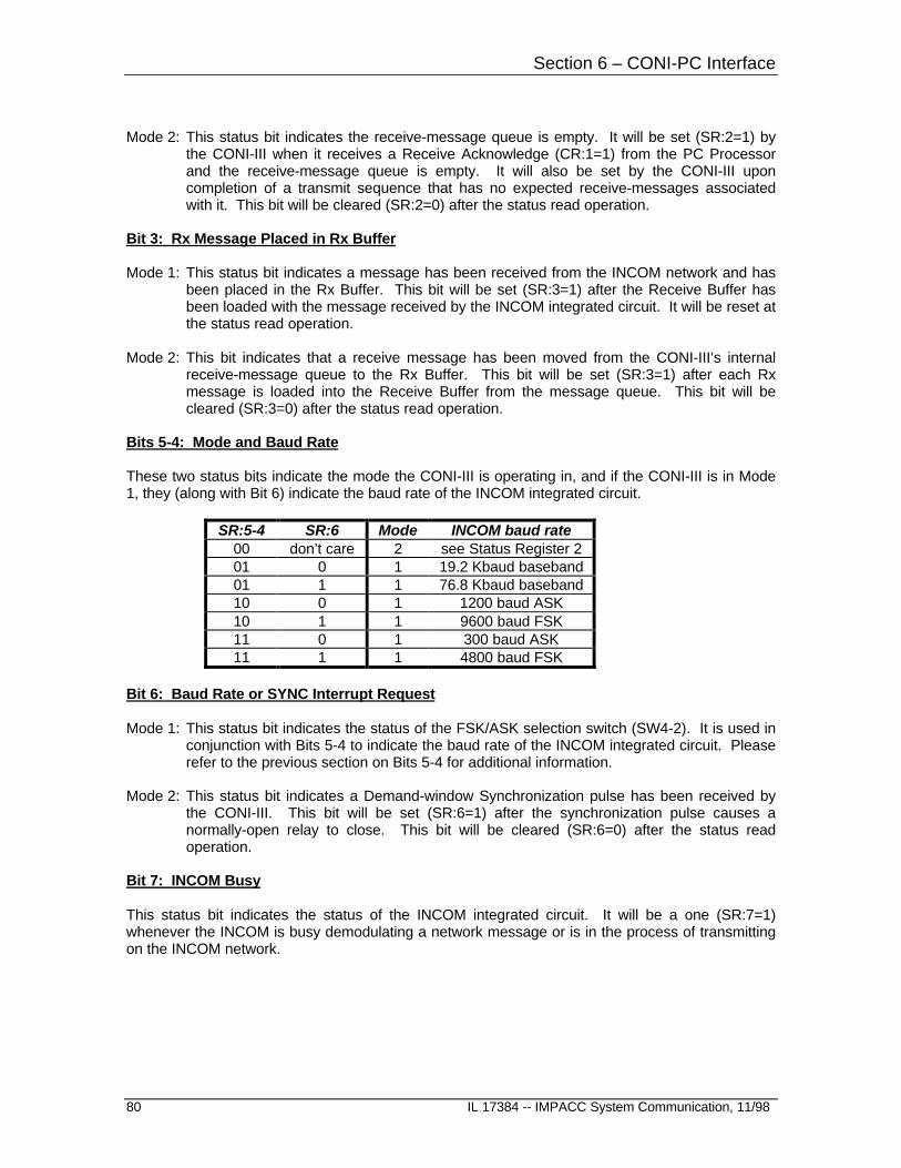
Section 6 – CONI-PC Interface
80 IL 17384 -- IMPACC System Communication, 11/98
Mode 2: This status bit indicates the receive-message queue is empty. It will be set (SR:2=1) bythe CONI-III when it receives a Receive Acknowledge (CR:1=1) from the PC Processorand the receive-message queue is empty. It will also be set by the CONI-III uponcompletion of a transmit sequence that has no expected receive-messages associatedwith it. This bit will be cleared (SR:2=0) after the status read operation.
Bit 3: Rx Message Placed in Rx Buffer
Mode 1: This status bit indicates a message has been received from the INCOM network and hasbeen placed in the Rx Buffer. This bit will be set (SR:3=1) after the Receive Buffer hasbeen loaded with the message received by the INCOM integrated circuit. It will be reset atthe status read operation.
Mode 2: This bit indicates that a receive message has been moved from the CONI-III’s internalreceive-message queue to the Rx Buffer. This bit will be set (SR:3=1) after each Rxmessage is loaded into the Receive Buffer from the message queue. This bit will becleared (SR:3=0) after the status read operation.
Bits 5-4: Mode and Baud Rate
These two status bits indicate the mode the CONI-III is operating in, and if the CONI-III is in Mode1, they (along with Bit 6) indicate the baud rate of the INCOM integrated circuit.
SR:5-4 SR:6 Mode INCOM baud rate00 don’t care 2 see Status Register 201 0 1 19.2 Kbaud baseband01 1 1 76.8 Kbaud baseband10 0 1 1200 baud ASK10 1 1 9600 baud FSK11 0 1 300 baud ASK11 1 1 4800 baud FSK
Bit 6: Baud Rate or SYNC Interrupt Request
Mode 1: This status bit indicates the status of the FSK/ASK selection switch (SW4-2). It is used inconjunction with Bits 5-4 to indicate the baud rate of the INCOM integrated circuit. Pleaserefer to the previous section on Bits 5-4 for additional information.
Mode 2: This status bit indicates a Demand-window Synchronization pulse has been received bythe CONI-III. This bit will be set (SR:6=1) after the synchronization pulse causes anormally-open relay to close. This bit will be cleared (SR:6=0) after the status readoperation.
Bit 7: INCOM Busy
This status bit indicates the status of the INCOM integrated circuit. It will be a one (SR:7=1)whenever the INCOM is busy demodulating a network message or is in the process of transmittingon the INCOM network.

Section 6 – CONI-PC Interface
IL 17384 -- IMPACC System Communications, 11/98 81
Status Register 2: xx9HEX (Read)
I/O Port xx9 -- Read Bit 7 Bit 0
T/ODis.
AuxCLevel
TxSeq.
Net-work Reserved=0 Baud Rate
| | | | | | | Network Selected (1 = Carrier, 0 = Baseband) | | | | | Transmit Sequence in Progress | | | Auxiliary Contact Input Level (0=Contact closed, 1=Contact open) | Time-out Disabled
Status Register 2 is used when the CONI-III is configured for Mode 2 operation. Status Register 2does not provide meaningful information when the CONI-III is configured for Mode 1.
Bits 1-0: Baud Rate
These two Status bits along with Status bit 4 indicate the baud rate of the INCOM communications.
SR2:1-0 SR2:4 Baud rate00 0 Invalid01 0 19.2 Kbaud (baseband)10 0 153.6 Kbaud (baseband)11 0 76.8 Kbaud (baseband)00 1 1200 baud ASK (carrier)01 1 300 baud ASK (carrier)10 1 9600 baud FSK (carrier)11 1 4800 baud FSK (carrier)
Bit 4: Transceiver Selection
This bit indicates the currently selected transceiver. A zero indicates the baseband transceiver wasselected via the most recent write to the Control Register. A one indicates the carrier transceiverwas selected via the most recent write to the Control Register. Please see the section entitled“Control Register:: xx8HEX (Write)” for additional information.
Bit 5: Transmit Sequence in Progress
This bit indicates the CONI-III is currently processing a transmit sequence. This TransmitSequence in Progress is set (SR2:5=1) by the CONI-III upon its receiving the Initiate Transmitcommand (CR:0=1) from the PC Processor. It will remain set until all of the queued transmit-messages are transmitted and all of the expected receive-messages are received (or timed-out).
Bit 6: Auxiliary Contact Input Level
This bit indicates the current level of the auxiliary contact input.
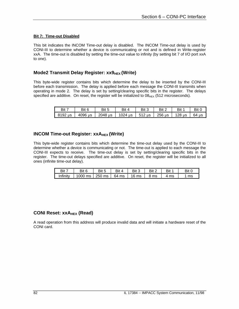
Section 6 – CONI-PC Interface
82 IL 17384 -- IMPACC System Communication, 11/98
Bit 7: Time-out Disabled
This bit indicates the INCOM Time-out delay is disabled. The INCOM Time-out delay is used byCONI-III to determine whether a device is communicating or not and is defined in Write-registerxxA. The time-out is disabled by setting the time-out value to infinity (by setting bit 7 of I/O port xxAto one).
Mode2 Transmit Delay Register: xx9HEX (Write)
This byte-wide register contains bits which determine the delay to be inserted by the CONI-IIIbefore each transmission. The delay is applied before each message the CONI-III transmits whenoperating in mode 2. The delay is set by setting/clearing specific bits in the register. The delaysspecified are additive. On reset, the register will be initialized to 08HEX (512 microseconds).
Bit 7 Bit 6 Bit 5 Bit 4 Bit 3 Bit 2 Bit 1 Bit 08192 µs 4096 µs 2048 µs 1024 µs 512 µs 256 µs 128 µs 64 µs
INCOM Time-out Register: xxAHEX (Write)
This byte-wide register contains bits which determine the time-out delay used by the CONI-III todetermine whether a device is communicating or not. The time-out is applied to each message theCONI-III expects to receive. The time-out delay is set by setting/clearing specific bits in theregister. The time-out delays specified are additive. On reset, the register will be initialized to allones (infinite time-out delay).
Bit 7 Bit 6 Bit 5 Bit 4 Bit 3 Bit 2 Bit 1 Bit 0Infinity 1000 ms 250 ms 64 ms 16 ms 8 ms 4 ms 1 ms
CONI Reset: xxAHEX (Read)
A read operation from this address will produce invalid data and will initiate a hardware reset of theCONI card.

Section 6 – CONI-PC Interface
IL 17384 -- IMPACC System Communications, 11/98 83
Status Register 3: xxBHEX (Read)
I/O Port xxB -- Read Bit 7 Bit 0
RxQO-F
TxQO-F
M/S Rsvd= 0
CONI-III FPGA Revision
| | | | | Master/Slave (1=INCOM network master, 0=INCOM network slave) | | | Tx Queue Over-flow | Rx Queue Over-flow
Status Register 3 is used when the CONI-III is configured for Mode 2 operation. Status Register 3does not provide meaningful information when the CONI-III is configured for Mode 1.
Bits 3-0: CONI-III FPGA Revision
These four bits indicate the revision of the CONI-III’s Field Programmable Gate Array.
SR3:3-0 FPGA Revision0000 Beta0001 Release 1
Bit 5: Master/Slave
This status bit is set (SR3:5=1) if switch SW1-3 is off – indicating the CONI-III is configured to be anINCOM network master. This status bit is reset (SR3:5=0) if switch SW1-3 if on – indicating theCONI-III is configured to be an INCOM network slave.
Bit 6: Tx Queue Over-flow
This status bit is set (SR3:6=1) if the PC Processor attempts to queue more transmit messagesthan can fit on the CONI-III (that is, more than 256). A correctly programmed PC Processor shouldprevent this error from occurring. If this error occurs, a reset command should be issued to theCONI-III.
Bit 7: Rx Queue Over-flow
This status bit is set (SR3:7=1) when the CONI-III receives more messages than can fit in thereceive-message queue. If and when this condition occurs, the CONI-III will suspend the receivingof INCOM messages until the PC Processor reads all of the messages in the receive-messagequeue (empties the queue). It is cleared (SR3:7=0) when the PC Processor acknowledges itsreceipt of the last receive-message in the queue.
Note: The receive-message queue does not wrap-around. The queue pointers are reset uponpower-up, when the CONI-III is reset, and when the PC Processor empties the queue (readsthe latest receive message).

Section 6 – CONI-PC Interface
84 IL 17384 -- IMPACC System Communication, 11/98
6.2 Initialization
The CONI is initialized by the hardware reset signal "PC_RESET" received from the IBM processorbus. Software reset is performed by reading address xxAh. After reset, the CONI will have thefollowing state:
• The contents of the RX and Tx Buffers are zero.• Status Register 1 contents will be one of the following values:
22h -- if the CONI-III’s switches are set for Mode 1 ASK operation.62h -- if the CONI-III’s switches are set for Mode 1 FSK operation.02h -- if the CONI-III’s switches are set for Mode 2 operation.
• Status Register 2 contents will be D2HEX. (Assumes the Aux contact input is open)• Status Register 3 contents will one of the following values: FPGA version number (00HEX - 0FHEX) for Mode 1 or Mode 2 master operation FPGA version number + 40HEX (40HEX - 4FHEX) for Mode 2 slave operation.• The carrier baud rate will be set to 1200 or 9600, depending on the FSK/ASK switch.• The baseband baud rate will be set to 153.6 kbaud• No message transmission will be in progress.• The CONI will be prepared to receive a message from the carrier-based INCOM
network.• The default value contained in the Time-out Register will be 0FFHEX, (The INCOM
Timeout will be disabled).• The default value contained in the Control Register will be 88HEX (Mode 2) or 80HEX
(Mode1).• The default value contained in the Mode2 Transmit Delay Register will be initialized to
08HEX (512 microseconds).
Note: After the PC Processor resets the CONI-III (reads port address xxAHEX), it must wait for a22h, 62h, or 02h to appear in the status register before issuing any commands (or writes) tothe CONI-III’s registers.
6.3 Mode 1 Operation
6.3.1 Transmit Operation for Mode 1
Whenever a message is to be transmitted, Status Register bit 0 (SR:0) should be checked todetermine if the Transmit Buffer is available to the PC processor. A one (1) indicates that the CONIhas not yet completed unloading the previous message from the Transmit Buffer. A zero in SR:0indicates that the Transmit Buffer is available and may be filled with a new message. After theTransmit Buffer has been loaded, the Initiate transmit bit in the Control Register (CR:0) should beset to request that the message in the Transmit Buffer be transmitted.
The CONI-III will set the Tx Buffer Not Available bit in the Status Register (SR:0=1) in response towriting CR:0=1. The new transmit message will be loaded into the INCOM integrated circuit when itis available. After the message has been loaded into the INCOM and transmission initiated, SR:0will be reset, an interrupt request set, and SR:2 set.
The PC processor can either poll the Status Register (SR:0) or respond to the interrupt request todetermine completion. Since bit 2 and 3 of the Status Register are reset after the status readoperation, the program must keep track of these completion flags. The hardware implementation of

Section 6 – CONI-PC Interface
IL 17384 -- IMPACC System Communications, 11/98 85
these flags (SR:2 & SR:3) will only reset each flag if it was read as a one. This prevents clearingthe flag erroneously if the status read and completion occur simultaneously.
The actual message transmission on the INCOM network will continue after the Status Registerupdate. The INCOM Busy flag (SR:7) will remain set until the message has been completelytransmitted by the INCOM. It should be remembered that the INCOM Busy flag (SR:7) is alsoasserted by receive operations of the INCOM.
6.3.2 Receive Operation in Mode 1
The CONI-III will receive all messages on the INCOM network except those transmitted by itself.Whenever a message is detected, the INCOM circuit will demodulate it and load the receivedmessage into its internal shift register. If the Receive Buffer is available at the completion of themessage (SR:1-0), the CONI-III will transfer the contents of the INCOM shift register to the ReceiveBuffer, set the Receiver Interrupt Request flag (SR:3=1), and request a PC processor interrupt. Ifthe Receive Buffer is not available (SR:1=1), the message will remain in the INCOM shift registeruntil the PC processor software releases the Receive Buffer by clearing SR:1.
When the PC processor responds to the Receiver Interrupt, or polls the Status Register (SR:3=1), itmay read the message stored in the Receive Buffer (304h - 307h). Caution must be exercised inreading the Status Register, since SR:2 and SR:3 are cleared after reading. A status of one (1) ineither of these bits indicates an operation has been completed by the CONI-III or the CONI-IIIrequires service. This status must be saved for processing by the appropriate software routine.
All messages should have the BCH Error Status flag checked for a data error (RB304:6=1) andshould be discarded if the flag is set. After the message has been read from the CONI, the PCprocessor must free the Receive Buffer for additional messages by setting the AcknowledgeReceive bit in the Control Register (CR:1=1). Failure to release the Receive Buffer will cause allfuture messages to be ignored by the CONI-III.
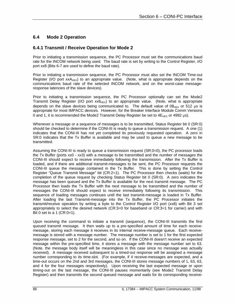
Section 6 – CONI-PC Interface
86 IL 17384 -- IMPACC System Communication, 11/98
6.4 Mode 2 Operation
6.4.1 Transmit / Receive Operation for Mode 2
Prior to initiating a transmission sequence, the PC Processor must set the communications baudrate for the INCOM network being used. The baud rate is set by writing to the Control Register, I/Oport xx8 (Bits 6-7 are used to define the baud rate).
Prior to initiating a transmission sequence, the PC Processor must also set the INCOM Time-outRegister (I/O port xxAHEX) to an appropriate value. (Note, what is appropriate depends on thecommunications baud rate of the selected INCOM network, and on the worst-case message-response latencies of the slave devices).
Prior to initiating a transmission sequence, the PC Processor optionally can set the Mode2Transmit Delay Register (I/O port xx8HEX) to an appropriate value. (Note, what is appropriatedepends on the slave devices being communicated to. The default value of 08HEX or 512 µs isappropriate for most IMPACC devices. However, for the Breaker Interface Module Comm Versions0 and 1, it is recommended the Mode2 Transmit Delay Register be set to 4EHEX or 4992 µs).
Whenever a message or a sequence of messages is to be transmitted, Status Register bit 0 (SR:0)should be checked to determine if the CONI-III is ready to queue a transmission request. A one (1)indicates that the CONI-III has not yet completed its previously requested operation. A zero inSR:0 indicates that the Tx Buffer is available and may be used to queue a new message to betransmitted.
Assuming the CONI-III is ready to queue a transmission request (SR:0=0), the PC processor loadsthe Tx Buffer (ports xx0 - xx3) with a message to be transmitted and the number of messages theCONI-III should expect to receive immediately following the transmission. After the Tx Buffer isloaded, and if there are additional transmit-messages to be sent, the PC Processor requests theCONI-III queue the message contained in the Tx Buffer. This is done by setting the ControlRegister “Queue Transmit Message” bit (CR:2=1). The PC Processor then checks (waits) for thecompletion of the queue request by checking Status Register bit 0 (SR:0). A zero indicates themessage has been queued and the Tx Buffer is available for the next transmit message. The PCProcessor then loads the Tx Buffer with the next message to be transmitted and the number ofmessages the CONI-III should expect to receive immediately following its transmission. Thissequence of loading messages continues until the last transmit-message is loaded in Tx Buffer.After loading the last Transmit-message into the Tx Buffer, the PC Processor initiates thetransmit/receive operation by writing a byte to the Control Register I/O port (xx8) with Bit 3 setappropriately to select the desired network (CR:3=0 for baseband or CR:3=1 for carrier) and withBit 0 set to a 1 (CR:0=1).
Upon receiving the command to initiate a transmit (sequence), the CONI-III transmits the firstqueued transmit message. It then waits up to a pre-specified amount of time for each receive-message, storing each message it receives in its internal receive-message queue. Each receive-message is stored with a message number. The message number is set to 1 for the first expectedresponse message, set to 2 for the second, and so on. If the CONI-III doesn’t receive an expectedmessage within the pre-specified time, it stores a message with the message number set to 63.(Note, the message body itself will be meaningless in this case since no message was actuallyreceived). A message received subsequent to a timed-out response will be assigned a messagenumber corresponding to its time-slot. (For example, if 4 receive-messages are expected, and atime-out occurs on the 2nd and 3rd messages, the CONI-III stores message numbers of 1, 63, 63,and 4 for the four messages respectively). Upon receiving the last expected message or upontiming-out on the last message, the CONI-III pauses momentarily (see Mode2 Transmit DelayRegister) and then transmits the second queued message and waits for its corresponding receive-

Section 6 – CONI-PC Interface
IL 17384 -- IMPACC System Communications, 11/98 87
messages. This process continues until all of the queued transmit-messages are transmitted andtheir response messages received (or timed-out). Upon completion, the CONI-III copies the firstmessage contained in the received-message queue to the Rx Buffer, sets Status Register Bit 3(SR:3=1), and requests a PC Processor Interrupt.
When the PC Processor responds to the Receive Interrupt, or polls the Status Register (SR:3=1), itmay read the message stored in the Rx Buffer (I/O ports xx4 - xx7). Note, caution must beexercised in reading the Status Register, since SR:2, SR:3, and SR:6 are cleared after reading. Astatus of one (1) in any of these bits indicates an operation has been completed by the CONI-III orthe CONI-III requires service. This status must be saved for processing by the appropriatesoftware routine.
After reading the message stored in the Rx Buffer, the PC Processor must free the Rx Buffer for thenext message by setting the Acknowledge Receive Bit in the Control Register (CR:1=1). Uponreceiving the Acknowledge Receive command, the CONI-III sets the Status Register “Rx Buffer NotAvailable” Bit (SR:1=1), and copies the next message contained in the receive-message queue tothe Rx Buffer. It then sets Status Register Bit 3 (SR:3=1), and requests another PC ProcessorInterrupt. This process continues until the last message stored in the receive-message queue istransferred to the PC Processor. After the PC Processor reads the last message and sets theAcknowledge Receive (CR:1=1), the CONI-III sets Status Register Bit 2 (Tx Queue Empty), andrequests a PC Processor Interrupt. This informs the PC Processor that the Tx Sequence iscomplete and that all receive-messages have been read from the CONI-III.
If and when the CONI-III receives an un-solicited message, it stores the message in its receive-message queue and sets its message number to zero (0).
Warnings:
Failure to release the Receive Buffer will prevent the CONI-III from informing the PC Processor ofthe presence of additional messages.
All messages should have the BCH Error Status flag checked for a data error (RB304:6=1) andshould be discarded if the flag is set.
All messages with message numbers of zero or 63 should be discarded.
All receive-messages from a transmit message sequence should be discarded if there are any un-solicited messages (messages with message number equal to zero) included in the responses.

Section 6 – CONI-PC Interface
88 IL 17384 -- IMPACC System Communication, 11/98
6.5 PC Interrupt Usage
The CONI-III can be configured to use IRQ 3, 4, 5, 7, or 9. This is configured via Switch SW2.
Note, IRQ3 is the COM 2 port interruptIRQ4 is the COM1 port interrupt.The uses for interrupts IRQ5, IRQ7, and IRQ9 may depend on the brand andmodel of the personal computer being used and the optional cards installed.
The IRQ assigned to the CONI-III must be unique, that is, not assigned to any other function in thepersonal computer.

Section 7
RS 232 / ASCII - to - INCOM
IL 17384 -- IMPACC System Communications, 11/98 89
7.0 RS 232/ASCII – to INCOM
Any computer or programmable device with an RS 232 communications port may function as anINCOM network master. An RS 232 based INCOM network master requires the use of a gatewaydevice such as the Westinghouse MINT (Master INCOM Network Translator), RS 232 PONI, orSeries III Gateway Interface. The gateway device converts the 33-bit binary messages used on theWestinghouse INCOM local area network to and from 10 byte ASCII encoded hexadecimal RS 232messages.
7.1 ASCII Message Formats
The format for the ASCII versions of the INCOM control and data message are shown below.
ASCII Control Message
Character Number
10 9 8 7 6 5 4 3 2 1 +-----+-----+-----+-----+-----+-----+-----+-----+-----+-----+ | Check Sum | Address |SCOMM|COMM |INST | C/D | STX | +-----+-----+-----+-----+-----+-----+-----+-----+-----+-----+
ASCII Data Message
Character Number
10 9 8 7 6 5 4 3 2 1 +-----+-----+-----+-----+-----+-----+-----+-----+-----+-----+ | Check Sum | Data | C/D | STX | +-----+-----+-----+-----+-----+-----+-----+-----+-----+-----+
Note that the format for the ASCII string is similar to that for the INCOM message with the followingexceptions.
1. The start-of-text control character STX replaces the two start bits.
2. The SCOMM character is moved to follow the COMM character rather than the address.
Note: This applies to control messages only. For data messagescontaining a "Pass Thru" control message for a device on asub-network, the SCOMM character follows the address field.
3. Besides distinguishing between control and data messages, the C/D character is also used to indicate a BCH error.
4. The two character check sum replaces the 5 bit BCH error code.
5. The check sum is the two least significant hex values of the sum of the number
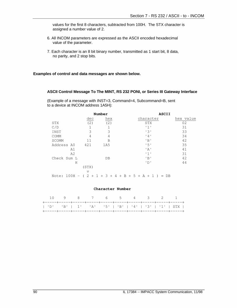
Section 7 - RS 232 / ASCII - to - INCOM
90 IL 17384 -- IMPACC System Communication, 11/98
values for the first 8 characters, subtracted from 100H. The STX character is assigned a number value of 2.
6. All INCOM parameters are expressed as the ASCII encoded hexadecimal value of the parameter.
7. Each character is an 8 bit binary number, transmitted as 1 start bit, 8 data, no parity, and 2 stop bits.
Examples of control and data messages are shown below.
ASCII Control Message To The MINT, RS 232 PONI, or Series III Gateway Interface
(Example of a message with INST=3, Command=4, Subcommand=B, sentto a device at INCOM address 1A5H):
Number ASCII dec hex character hex value
STX (2) (2) STX 02 C/D 1 1 '1' 31 INST 3 3 '3' 33 COMM 4 4 '4' 34 SCOMM 11 B 'B' 42 Address A0 421 1A5 '5' 35 A1 'A' 41 A2 '1' 31 Check Sum L DB 'B' 42 H 'D' 44 (STX) v Note: 100H - ( 2 + 1 + 3 + 4 + B + 5 + A + 1 ) = DB
Character Number
10 9 8 7 6 5 4 3 2 1 +-----+-----+-----+-----+-----+-----+-----+-----+-----+-----+ | 'D' 'B' | 1' 'A' '5' | 'B' | '4' | '3' | '1' | STX | +-----+-----+-----+-----+-----+-----+-----+-----+-----+-----+

Section 7 – RS 232 / ASCII - to - INCOM
IL 17384 -- IMPACC System Communications, 11/98 91
ASCII Control Message Received from the MINT, RS 232 PONI, or Series III Gateway Interface (No BCH Error)
(Example of a message with INST=3, Command=4, Subcommand=B):
Number ASCII dec hex character hex value STX (2) (2) STX 02 C/D 2 2 '2' 32 INST 3 3 '3' 33 COMM 4 4 '4' 34 SCOMM 11 B 'B' 42 Address A0 421 1A5 '5' 35 A1 'A' 41 A2 '1' 31 Check Sum L DA 'A' 41 H 'D' 44 (STX) v Note: 100H - ( 2 + 2 + 3 + 4 + B + 5 + A + 1 ) = DA
Character Number
10 9 8 7 6 5 4 3 2 1 +-----+-----+-----+-----+-----+-----+-----+-----+-----+-----+ | 'D' 'A' | 1' 'A' '5' | 'B' | '4' | '3' | '2' | STX | +-----+-----+-----+-----+-----+-----+-----+-----+-----+-----+
ASCII Data Message to or from a MINT, RS 232 PONI, or Series III Gateway Interface (No BCH Error)(Example of a message with the data field set to 0D4AD31H):
number ASCII dec hex character hex value
STX (2) (2) STX 02 C/D 0 0 '0' 30 BYTE0 lsn 49 31 '1' 31 msn '3' 33 BYTE1 lsn 173 AD 'D' 44 msn 'A' 41 BYTE2 lsn 212 D4 '4' 34 msn 'D' 44 Check Sum L D2 '2' 32 H 'D' 44 (STX) v Note: 100H - ( 2 + 0 + 1 + 3 + D + A + 4 + D ) = D2
Character Number
10 9 8 7 6 5 4 3 2 1 +-----+-----+-----+-----+-----+-----+-----+-----+-----+-----+ | 'D' '2' | 'D' '4' 'A' 'D' '3' '1' | '1' | STX | +-----+-----+-----+-----+-----+-----+-----+-----+-----+-----+

Section 7 - RS 232 / ASCII - to - INCOM
92 IL 17384 -- IMPACC System Communication, 11/98
7.2 BCH Error and Data Flow Control ASCII Messages
7.2.1 BCH Error Characters
Should the MINT (or RS 232 PONI) receive a transmission from a product that contains a BCHerror there is no separate character available in the 10 character string that can be used to informthe host that the message had an error. The C/D character is used for this purpose and thus C/D isdefined differently when it is part of the ASCII string than when it is part of an INCOM message.These different definitions are listed below.
Messages from the host to the MINT, RS 232 PONI, or Series III Gateway Interface
C/D INCOM ASCII
'0' data data'1' control control
Messages from the MINT (or RS 232 PONI) to the host
C/D INCOM ASCII
'0' data data, no BCH error'1' data data, with BCH error'2' control control, no BCH error'3' control control, with BCH error
Messages from the Series III Gateway Interface to the host
C/D INCOM ASCII
'0' data data, no BCH error'2' control data, no BCH error

Section 7 – RS 232 / ASCII - to - INCOM
IL 17384 -- IMPACC System Communications, 11/98 93
7.2.2 Data Flow Control Characters
In order to control the data flow and other functions of the RS232 Channel, several specialcharacters are used in addition to those already discussed. All of the legal characters arepresented in the following table together with notes on their function.
HEX VALID VALID CHAR CHAR CODE Tx Rx DESCRIPTION
<STX> CTRL-B 02H X X Start of ten byte message <ACK> CTRL-F 06H X Format message acknowledge <LF> CTRL-J 0AH X Used for echo screen display <CR> CTRL-M 0DH X Used for echo screen <XON> CTRL-G 11H X X gateway ready to accept data <DC2> CTRL-R 12H X Turn on gateway echoing <XOFF> CTRL-S 13H X X gateway not able to accept data <DC4> CTRL-T 14H X Turn off gateway echoing <NAK> CTRL-U 15H X Format message not acknowledge '0'-'9' 30-39H X ASCII encoded HEX numerics 'A'-'F' 41-46H X ASCII encode HEX alphas 'A' 41H X Echo format acknowledge 'N' 4EH X Echo format not acknowledge 'a'-'f' 61-66H X ASCII encoded HEX alphas
Notes:
1) An <ACK> or <NAK> is sent to the host by the gateway device (MINT, RS 232 PONI, or Series III Gateway Interface) immediately following the reception of a 10-character message. An <ACK> is sent if the 10 characters are valid (legal) and if the checksum is correct. A <NAK> is sent if an invalid (non-supported) character is received or if the checksum is incorrect.
2) All characters received will be echoed when the echoing is active.
3) An <XOFF> is sent immediately after two characters of a new message are received and the previous message processing is not yet completed. An <XON> is sent only when <XOFF> has been sent, and is transmitted when the previous message processing has completed (freed the input INCOM buffer). Hardware start/stop control of data flow is performed 1 byte prior to this software control.
An RS232 Device communicating through a gateway may stop and start the data flow by sending the <XON> and <XOFF> characters.
4) When echoing is active (on), reception of a <CR> by the gateway will cause a <CR> and <LF> to be echoed by it. This may cause double spacing on a master device display.
5) Reception of lower case HEX alphas are converted to hex values inside the gateway but are echoed as upper case characters.

Section 7 - RS 232 / ASCII - to - INCOM
94 IL 17384 -- IMPACC System Communication, 11/98
6) Within a 10 byte data stream representing a message from a master device, <LF>, <CR>, <DC2>, <RUB>, and <BS> are ignored as far as byte count for the message is concerned. They will not interfere with the gateway receiving a valid message if interspersed within the message (this would not normally occur).
7) Any characters not in the above table and in the valid RX column are considered bad characters and counted in the message byte count, but will cause a formatting error and subsequent <NAK> to be sent when the message is complete. Characters not counted at all include <CR>, <LF>,<DC2> and <DC4>.
7.3 RS232C Hardware Specifications
The gateway device physical interface is a 25 pin "D" subminiature connector that utilizes theminimum 3-wire configuration outlined in the RS232C standard. These three wires consist of TX,RX and common. The pins are designated as shown below. The interface cable is user supplied.The IMPACC gateways utilize an 8 bit data word with 1 start, 2 stop bits and no parity bit. Thespeed is gateway dependent. All gateways support a BAUD rate of 1200 bps.
HOST IMPACC GATEWAY
RS232 PORT MINT/RS 232 PONI/SERIES III GATEWAY INTERFACE
9 pin "D" 25 pin "D" 25 pin "D" pin number pin number pin number
3 2 --- TX --> 2 2 3 <-- RX --- 3 5 7 common 7