Part 9 9.12 Rev Clean - IN.gov 9A - 9D...01 General information and definitions concerning traffic...
28
2011 IMUCTD Page 815 November 2011 Sect. 9A..0815 to 9A..08 PART 9 TRAFFIC CONTROL FOR BICYCLE FACILITIES CHAPTER 9A. GENERAL Section 9A.01 Requirements for Bicyclist Traffic Control Devices Support: 01 General information and definitions concerning traffic control devices are found in Part 1. Section 9A.02 Scope Support: 01 Part 9 covers signs, pavement markings, and highway traffic signals specifically related to bicycle operation on both roadways and shared-use paths. Guidance: 02 Parts 1, 2, 3, and 4 should be reviewed for general provisions, signs, pavement markings, and signals. Standard: 03 The absence of a marked bicycle lane or any of the other traffic control devices discussed in this Chapter on a particular roadway shall not be construed to mean that bicyclists are not permitted to travel on that roadway. Section 9A.03 Definitions Relating to Bicycles Support: 01 Definitions and acronyms pertaining to Part 9 are provided in Sections 1A.13 and 1A.14. Section 9A.04 Maintenance Guidance: 01 All signs, signals, and markings, including those on bicycle facilities, should be properly maintained to command respect from both the motorist and the bicyclist. When installing signs and markings on bicycle facilities, an agency should be designated to maintain these devices. Section 9A.05 Relation to Other Documents Support: 01 “The Uniform Vehicle Code and Model Traffic Ordinance” published by the National Committee on Uniform Traffic Laws and Ordinances (see Section 1A.11) has provisions for bicycles and is the basis for the traffic control devices included in this Manual. 02 Informational documents used during the development of the signing and marking recommendations in Part 9 include the following: A. “Guide for Development of Bicycle Facilities,” which is available from the American Association of State Highway and Transportation Officials (see Page i for the address); and B. State and local government design guides. 03 Other publications that relate to the application of traffic control devices in general are listed in Section 1A.11. Section 9A.06 Placement Authority Support: 01 Section 1A.08 contains information regarding placement authority for traffic control devices. Section 9A.07 Meaning of Standard, Guidance, Option, and Support Support: 01 Paragraph 1 of Section 1A.13 contains information regarding the meaning of the headings Standard, Guidance, Option, and Support, and the use of the words “shall,” “should,” and “may.” Section 9A.08 Colors Support: 01 Section 1A.12 contains information regarding the color codes.
Transcript of Part 9 9.12 Rev Clean - IN.gov 9A - 9D...01 General information and definitions concerning traffic...
2011 IMUCTD Page 815
November 2011 Sect. 9A..0815 to 9A..08
PART 9 TRAFFIC CONTROL FOR BICYCLE FACILITIES
CHAPTER 9A. GENERAL
Section 9A.01 Requirements for Bicyclist Traffic Control Devices Support:
01 General information and definitions concerning traffic control devices are found in Part 1.
Section 9A.02 Scope Support:
01 Part 9 covers signs, pavement markings, and highway traffic signals specifically related to bicycle operation on both roadways and shared-use paths. Guidance:
02 Parts 1, 2, 3, and 4 should be reviewed for general provisions, signs, pavement markings, and signals. Standard:
03 The absence of a marked bicycle lane or any of the other traffic control devices discussed in this Chapter on a particular roadway shall not be construed to mean that bicyclists are not permitted to travel on that roadway.
Section 9A.03 Definitions Relating to Bicycles Support:
01 Definitions and acronyms pertaining to Part 9 are provided in Sections 1A.13 and 1A.14. Section 9A.04 Maintenance
Guidance: 01 All signs, signals, and markings, including those on bicycle facilities, should be properly maintained to
command respect from both the motorist and the bicyclist. When installing signs and markings on bicycle facilities, an agency should be designated to maintain these devices.
Section 9A.05 Relation to Other Documents
Support:
01 “The Uniform Vehicle Code and Model Traffic Ordinance” published by the National Committee on Uniform Traffic Laws and Ordinances (see Section 1A.11) has provisions for bicycles and is the basis for the traffic control devices included in this Manual.
02 Informational documents used during the development of the signing and marking recommendations in Part 9 include the following:
A. “Guide for Development of Bicycle Facilities,” which is available from the American Association of State Highway and Transportation Officials (see Page i for the address); and
B. State and local government design guides. 03 Other publications that relate to the application of traffic control devices in general are listed in Section 1A.11.
Section 9A.06 Placement Authority Support:
01 Section 1A.08 contains information regarding placement authority for traffic control devices.
Section 9A.07 Meaning of Standard, Guidance, Option, and Support Support:
01 Paragraph 1 of Section 1A.13 contains information regarding the meaning of the headings Standard, Guidance, Option, and Support, and the use of the words “shall,” “should,” and “may.”
Section 9A.08 Colors Support:
01 Section 1A.12 contains information regarding the color codes.
Page 816 2011 IMUCTD
Sect. 9B.816 to 9B.07 November 2011
CHAPTER 9B. SIGNS
Section 9B .01 Application and Placement of Signs
Standard: 01 Bicycle signs shall be standard in shape, legend, and color. 02 All signs shall be retroreflectorized for use on bikeways, including shared-use paths and bicycle lane facilities. 03 Where signs serve both bicyclists and other road users, vertical mounting height and lateral placement
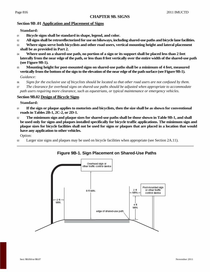
shall be as provided in Part 2. 04 Where used on a shared-use path, no portion of a sign or its support shall be placed less than 2 feet
laterally from the near edge of the path, or less than 8 feet vertically over the entire width of the shared-use path (see Figure 9B-1).
05 Mounting height for post-mounted signs on shared-use paths shall be a minimum of 4 feet, measured vertically from the bottom of the sign to the elevation of the near edge of the path surface (see Figure 9B-1).
Guidance: 06 Signs for the exclusive use of bicyclists should be located so that other road users are not confused by them. 07 The clearance for overhead signs on shared-use paths should be adjusted when appropriate to accommodate
path users requiring more clearance, such as equestrians, or typical maintenance or emergency vehicles.
Section 9B.02 Design of Bicycle Signs Standard:
01 If the sign or plaque applies to motorists and bicyclists, then the size shall be as shown for conventional roads in Tables 2B-1, 2C-2, or 2D-1.
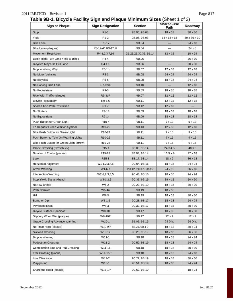
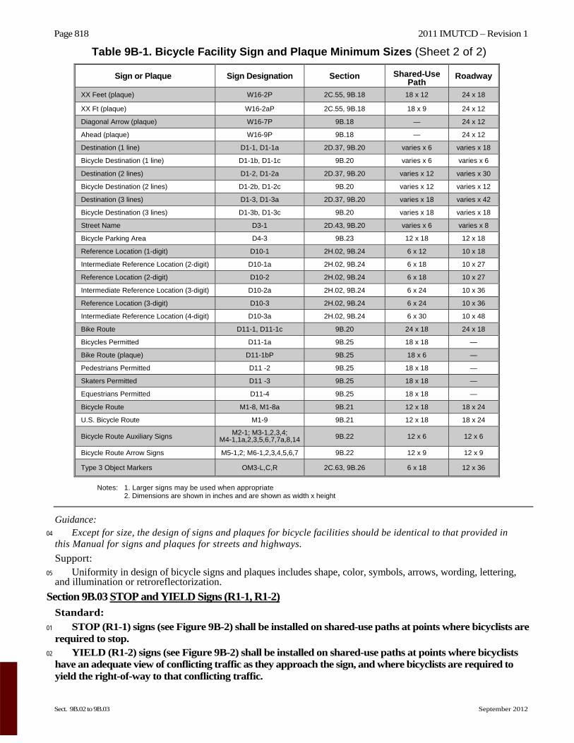
02 The minimum sign and plaque sizes for shared-use paths shall be those shown in Table 9B-1, and shall be used only for signs and plaques installed specifically for bicycle traffic applications. The minimum sign and plaque sizes for bicycle facilities shall not be used for signs or plaques that are placed in a location that would have any application to other vehicles. Option:
03 Larger size signs and plaques may be used on bicycle facilities when appropriate (see Section 2A.11).
Figure 9B-1. Sign Placement on Shared-Use Paths
2011 IMUTCD – Revision 1 Page 817
September 2012 Sect. 9B.02
Table 9B-1. Bicycle Facility Sign and Plaque Minimum Sizes (Sheet 1 of 2) Sign or Plaque Sign Designation Section Shared-Use
Path Roadway
Stop R1-1 2B.05, 9B.03 18 x 18 30 x 30
Yield R1-2 2B.08, 9B.03 18 x 18 x 18 30 x 30 x 30
Bike Lane R3-17 9B.04 — 24 x 18
Bike Lane (plaques) R3-17aP, R3-17bP 9B.04 — 24 x 8
Movement Restriction R4-1,2,3,7,16 2B.28,29,30,32; 9B.14 12 x 18 18 x 24
Begin Right Turn Lane Yield to Bikes R4-4 9B.05 — 36 x 30
Bicycles May Use Full Lane R4-1 1 9B.06 — 30 x 30
Bicycle Wrong Way R5-1b 9B.07 12 x 18 12 x 18
No Motor Vehicles R5-3 9B.08 24 x 24 24 x 24
No Bicycles R5-6 9B.09 18 x 18 24 x 24
No Parking Bike Lane R7-9,9a 9B.10 — 12 x 18
No Pedestrians R9-3 9B.09 18 x 18 18 x 18
Ride With Traffic (plaque) R9-3cP 9B.07 12 x 12 12 x 12
Bicycle Regulatory R9-5,6 9B.11 12 x 18 12 x 18
Shared-Use Path Restriction R9-7 9B.12 12 x 18 —
No Skaters R9-13 9B.09 18 x 18 18 x 18
No Equestrians R9-14 9B.09 18 x 18 18 x 18
Push Button for Green Light R10-4 9B.11 9 x 12 9 x 12
To Request Green Wait on Symbol R10-22 9B.13 12 x 18 12 x 18
Bike Push Button for Green Light R10-24 9B.11 9 x 15 9 x 15
Push Button to Turn On Warning Lights R10-25 9B.11 9 x 12 9 x 12
Bike Push Button for Green Light (arrow) R10-26 9B.11 9 x 15 9 x 15
Grade Crossing (Crossbuck) R15-1 8B.03, 9B.14 24 x 4.5 48 x 9
Number of Tracks (plaque) R15-2P 8B.03, 9B.14 13.5 x 9 27 x 18
Look R15-8 8B.17, 9B.14 18 x 9 36 x 18
Horizontal Alignment W1-1,2,3,4,5 2C.04, 9B.15 18 x 18 24 x 24
Arrow Warning W1-6,7 2C.12, 2C.47, 9B.15 24 x 12 36 x 18
Intersection Warning W2-1,2,3,4,5 2C.46, 9B.16 18 x 18 24 x 24
Stop,Yield, Signal Ahead W3-1,2,3 2C.36, 9B.19 18 x 18 30 x 30
Narrow Bridge W5-2 2C.20, 9B.19 18 x 18 30 x 30
Path Narrows W5-4a 9B.19 18 x 18 —
Hill W7-5 9B.19 18 x 18 30 x 30
Bump or Dip W8-1,2 2C.28, 9B.17 18 x 18 24 x 24
Pavement Ends W8-3 2C.30, 9B.17 18 x 18 30 x 30
Bicycle Surface Condition W8-10 9B.17 18 x 18 30 x 30
Slippery When Wet (plaque) W8-10P 9B.17 12 x 9 12 x 9
Grade Crossing Advance Warning W10-1 8B.06, 9B.19 24 Dia. 36 Dia.
No Train Horn (plaque) W10-9P 8B.21, 9B.1 9 18 x 12 30 x 24
Skewed Crossing W10-12 8B.25, 9B.19 18 x 18 36 x 36
Bicycle Warning W11-1 9B.18 18 x 18 24 x 24
Pedestrian Crossing W11-2 2C.50, 9B.19 18 x 18 24 x 24
Combination Bike and Ped Crossing W11-15 9B.18 18 x 18 30 x 30
Trail Crossing (plaque) W11-15P 9B.18 18 x 12 24 x 18
Low Clearance W12-2 2C.27, 9B.19 18 x 18 30 x 30
Playground W15-1 2C.51, 9B.19 18 x 18 24 x 24
Share the Road (plaque) W16-1P 2C.60, 9B.19 — 18 x 24
Page 818 2011 IMUTCD – Revision 1
Sect. 9B.02 to 9B.03 September 2012
Table 9B-1. Bicycle Facility Sign and Plaque Minimum Sizes (Sheet 2 of 2)
Sign or Plaque Sign Designation Section Shared-Use Path
Roadway
XX Feet (plaque) W16-2P 2C.55, 9B.18 18 x 12 24 x 18
XX Ft (plaque) W16-2aP 2C.55, 9B.18 18 x 9 24 x 12
Diagonal Arrow (plaque) W16-7P 9B.18 — 24 x 12
Ahead (plaque) W16-9P 9B.18 — 24 x 12
Destination (1 line) D1-1, D1-1a 2D.37, 9B.20 varies x 6 varies x 18
Bicycle Destination (1 line) D1-1b, D1-1c 9B.20 varies x 6 varies x 6
Destination (2 lines) D1-2, D1-2a 2D.37, 9B.20 varies x 12 varies x 30
Bicycle Destination (2 lines) D1-2b, D1-2c 9B.20 varies x 12 varies x 12
Destination (3 lines) D1-3, D1-3a 2D.37, 9B.20 varies x 18 varies x 42
Bicycle Destination (3 lines) D1-3b, D1-3c 9B.20 varies x 18 varies x 18
Street Name D3-1 2D.43, 9B.20 varies x 6 varies x 8
Bicycle Parking Area D4-3 9B.23 12 x 18 12 x 18
Reference Location (1-digit) D10-1 2H.02, 9B.24 6 x 12 10 x 18
Intermediate Reference Location (2-digit) D10-1a 2H.02, 9B.24 6 x 18 10 x 27
Reference Location (2-digit) D10-2 2H.02, 9B.24 6 x 18 10 x 27
Intermediate Reference Location (3-digit) D10-2a 2H.02, 9B.24 6 x 24 10 x 36
Reference Location (3-digit) D10-3 2H.02, 9B.24 6 x 24 10 x 36
Intermediate Reference Location (4-digit) D10-3a 2H.02, 9B.24 6 x 30 10 x 48
Bike Route D11-1, D11-1c 9B.20 24 x 18 24 x 18
Bicycles Permitted D11-1a 9B.25 18 x 18 —
Bike Route (plaque) D11-1bP 9B.25 18 x 6 —
Pedestrians Permitted D11 -2 9B.25 18 x 18 —
Skaters Permitted D11 -3 9B.25 18 x 18 —
Equestrians Permitted D11-4 9B.25 18 x 18 —
Bicycle Route M1-8, M1-8a 9B.21 12 x 18 18 x 24
U.S. Bicycle Route M1-9 9B.21 12 x 18 18 x 24
Bicycle Route Auxiliary Signs M2-1; M3-1,2,3,4; M4-1,1a,2,3,5,6,7,7a,8,14 9B.22 12 x 6 12 x 6
Bicycle Route Arrow Signs M5-1,2; M6-1,2,3,4,5,6,7 9B.22 12 x 9 12 x 9
Type 3 Object Markers OM3-L,C,R 2C.63, 9B.26 6 x 18 12 x 36
Notes: 1. Larger signs may be used when appropriate 2. Dimensions are shown in inches and are shown as width x height
Guidance: 04 Except for size, the design of signs and plaques for bicycle facilities should be identical to that provided in
this Manual for signs and plaques for streets and highways.
Support: 05 Uniformity in design of bicycle signs and plaques includes shape, color, symbols, arrows, wording, lettering,
and illumination or retroreflectorization.
Section 9B.03 STOP and YIELD Signs (R1-1, R1-2)
Standard:
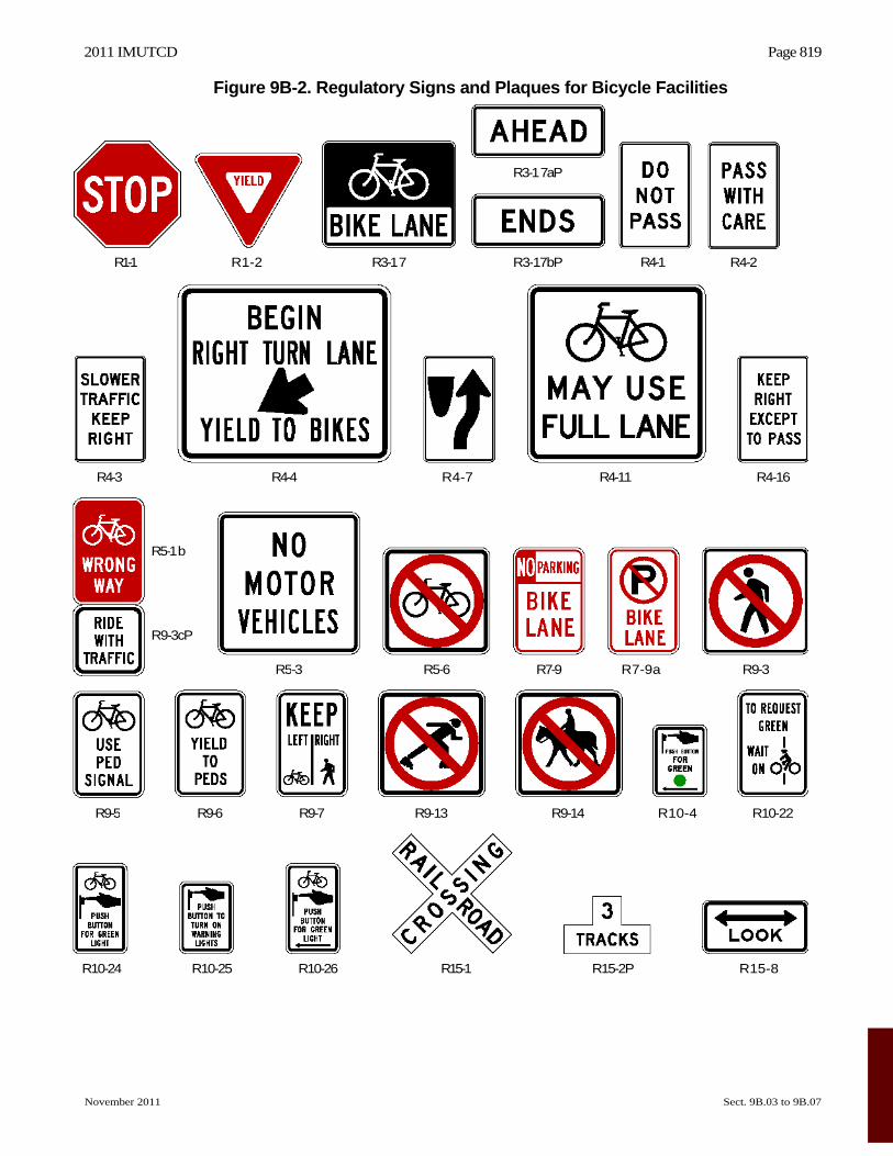
01 STOP (R1-1) signs (see Figure 9B-2) shall be installed on shared-use paths at points where bicyclists are required to stop.
02 YIELD (R1-2) signs (see Figure 9B-2) shall be installed on shared-use paths at points where bicyclists have an adequate view of conflicting traffic as they approach the sign, and where bicyclists are required to yield the right-of-way to that conflicting traffic.
2011 IMUTCD Page 819
November 2011 Sect. 9B.03 to 9B.07
Figure 9B-2. Regulatory Signs and Plaques for Bicycle Facilities
R10-24 R10-25 R10-26 R15-1 R15-2P R15-8
R4-2R4-1 R3-1 7
R3-1 7aP
R4-11 R4-16R4-3 R4-4 R4-7
R3-17bPR1-1 R1-2
R9-5 R9-6 R9-7 R9-13 R9-14 R10-4
R5-1 b
R9-3cP
R5-3 R5-6 R7-9 R7-9a R9-3
R10-22
Page 820
2011 IMUTCDOption:
03 A 30 x 30-inch STOP sign or a 36 x 36 x 36-inch YIELD sign may be used on shared-use paths for added emphasis. Guidance:
04 Where conditions require path users, but not roadway users, to stop or yield, the STOP or YIELD sign should be placed or shielded so that it is not readily visible to road users.
05 When placement of STOP or YIELD signs is considered, priority at a shared-use path/roadway intersection should be assigned with consideration of the following:
A. Relative speeds of shared-use path and roadway users, B. Relative volumes of shared-use path and roadway traffic, and C. Relative importance of shared-use path and roadway.
06 Speed should not be the sole factor used to determine priority, as it is sometimes appropriate to give priority to a high-volume shared-use path crossing a low-volume street, or to a regional shared-use path crossing a minor collector street.
07 When priority is assigned, the least restrictive control that is appropriate should be placed on the lower priority approaches. STOP signs should not be used where YIELD signs would be acceptable.
Section 9B.04 Bike Lane Signs and Plaques (R3-17, R3-17aP, R3-17bP) Standard:
01 The BIkE LANE (R3-17) sign and the R3-17aP and R3-17bP plaques (see Figure 9B-2) shall be used only in conjunction with marked bicycle lanes as described in Section 9C.04. Guidance:
02 If used, Bike Lane signs and plaques should be used in advance of the upstream end of the bicycle lane, at the downstream end of the bicycle lane, and at periodic intervals along the bicycle lane as determined by engineering judgment based on prevailing speed of bicycle and other traffic, block length, distances from adjacent intersections, and other considerations.
Section 9B.05 BEGIN RIGHT TURN LANE YIELD TO BIKES Sign (R4-4) Option:
01 Where motor vehicles entering an exclusive right-turn lane must weave across bicycle traffic in bicycle lanes, the BEGIN RIGHT TURN LANE YIELD TO BIKES (R4-4) sign (see Figure 9B-2) may be used to inform both the motorist and the bicyclist of this weaving maneuver (see Figures 9C-1, 9C-4, and 9C-5). Guidance:
02 The R4-4 sign should not be used when bicyclists need to move left because of a right-turn lane drop situation.
Section 9B.06 Bicycles May Use Full Lane Sign (R4-11) Option:
01 The Bicycles May Use Full Lane (R4-11) sign (see Figure 9B-2) may be used on roadways where no bicycle lanes or adjacent shoulders usable by bicyclists are present and where travel lanes are too narrow for bicyclists and motor vehicles to operate side by side.
02 The Bicycles May Use Full Lane sign may be used in locations where it is important to inform road users that bicyclists might occupy the travel lane.
03 Section 9C.07 describes a Shared Lane Marking that may be used in addition to or instead of the Bicycles May Use Full Lane sign to inform road users that bicyclists might occupy the travel lane. Support:
04 The Uniform Vehicle Code (UVC) defines a “substandard width lane” as a “lane that is too narrow for a bicycle and a vehicle to travel safely side by side within the same lane.”
Section 9B.07 Bicycle WRONG WAy Sign and RIDE WITH TRAFFIC Plaque (R5-1b, R9-3cP) Option:
01 The Bicycle WRONG WAY (R5-1b) sign and RIDE WITH TRAFFIC (R9-3cP) plaque (see Figure 9B-2) may be placed facing wrong-way bicycle traffic, such as on the left side of a roadway.
02 This sign and plaque may be mounted back-to-back with other signs to minimize visibility to other traffic.
Sect. 9B.03 to 9B.07 November 2011
2011 IMUTCD Page 821
November 2011 Sect. 9B.07 to 9B.12
Guidance: 03 The RIDE WITH TRAFFIC plaque should be used only in conjunction with the Bicycle WRONG WAY sign,
and should be mounted directly below the Bicycle WRONG WAY sign.
Section 9B.08 NO MOTOR VEHICLES Sign (R5-3) Option:
01 The NO MOTOR VEHICLES (R5-3) sign (see Figure 9B-2) may be installed at the entrance to a shared-use path.
Section 9B.09 Selective Exclusion Signs
Option: 01 Selective Exclusion signs (see Figure 9B-2) may be installed at the entrance to a roadway or facility to notify
road or facility users that designated types of traffic are excluded from using the roadway or facility. Standard:
02 If used, Selective Exclusion signs shall clearly indicate the type of traffic that is excluded. Support:
03 Typical exclusion messages include: A. No Bicycles (R5-6), B. No Pedestrians (R9-3), C. No Skaters (R9-13), and D. No Equestrians (R9-14).
Option: 04 Where bicyclists, pedestrians, and motor-driven cycles are all prohibited, it may be more desirable to use the
R5-10a word message sign that is described in Section 2B.39.
Section 9B.10 No Parking Bike Lane Signs (R7-9, R7-9a) Standard:
01 If the installation of signs is necessary to restrict parking, standing, or stopping in a bicycle lane, appropriate signs as described in Sections 2B.46 through 2B.48, or the No Parking Bike Lane (R7-9 or R7-9a) signs (see Figure 9B-2) shall be installed.
Section 9B.11 Bicycle Regulatory Signs (R9-5, R9-6, R10-4, R10-24, R10-25, and R10-26) Option:
01 The R9-5 sign (see Figure 9B-2) may be used where the crossing of a street by bicyclists is controlled by pedestrian signal indications.
02 Where it is not intended for bicyclists to be controlled by pedestrian signal indications, the R10-4, R10-24, or R10-26 sign (see Figure 9B-2 and Section 2B.52) may be used. Guidance:
03 If used, the R9-5, R10-4, R10-24, or R10-26 signs should be installed near the edge of the sidewalk in the vicinity of where bicyclists will be crossing the street. Option:
04 If bicyclists are crossing a roadway where In-Roadway Warning Lights (see Section 4N.02) or other warning lights or beacons have been provided, the R10-25 sign (see Figure 9B-2) may be used.
05 The R9-6 sign (see Figure 9B-2) may be used where a bicyclist is required to cross or share a facility used by pedestrians and is required to yield to the pedestrians.
Section 9B.12 Shared-Use Path Restriction Sign (R9-7) Option:
01 The Shared-Use Path Restriction (R9-7) sign (see Figure 9B-2) may be installed to supplement a solid white pavement marking line (see Section 9C.03) on facilities that are to be shared by pedestrians and bicyclists in order to provide a separate designated pavement area for each mode of travel. The symbols may be switched as appropriate. Guidance:
02 If two-way operation is permitted on the facility for pedestrians and/or bicyclists, the designated pavement area that is provided for each two-way mode of travel should be wide enough to accommodate both directions of travel for that mode.
Page 822 2011 IMUTCD
Sect. 9B.13 to 9B.18 November 2011
Section 9B.13 Bicycle Signal Actuation Sign (R10-22) Option:
01 The Bicycle Signal Actuation (R10-22) sign (see Figure 9B-2) may be installed at signalized intersections where markings are used to indicate the location where a bicyclist is to be positioned to actuate the signal (see Section 9C.05).
Guidance: 02 If the Bicycle Signal Actuation sign is installed, it should be placed at the roadside adjacent to the marking to
emphasize the connection between the marking and the sign.
Section 9B.14 Other Regulatory Signs Option:
01 Other regulatory signs described in Chapter 2B may be installed on bicycle facilities as appropriate.
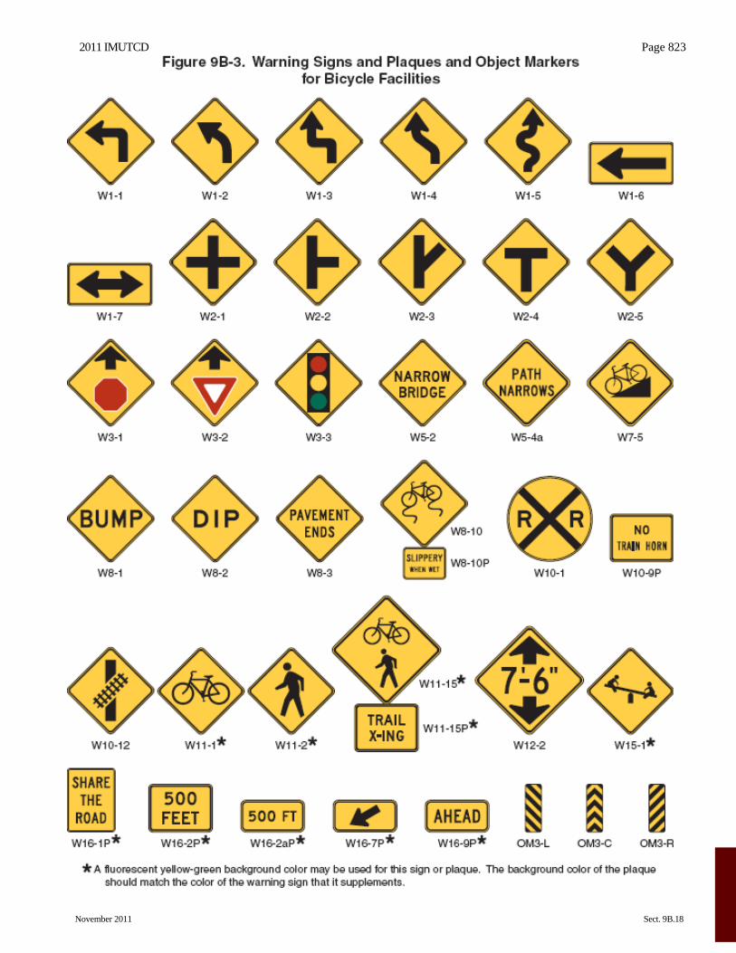
Section 9B.15 Turn or Curve Warning Signs (W1 Series) Guidance:
01 To warn bicyclists of unexpected changes in shared-use path direction, appropriate turn or curve (W1-1 through W1-7) signs (see Figure 9B-3) should be used.
02 The W1-1 through W1-5 signs should be installed at least 50 feet in advance of the beginning of the change of alignment.
Section 9B.16 Intersection Warning Signs (W2 Series) Option:
01 Intersection Warning (W2-1 through W2-5) signs (see Figure 9B-3) may be used on a roadway, street, or shared-use path in advance of an intersection to indicate the presence of an intersection and the possibility of turning or entering traffic. Guidance:
02 When engineering judgment determines that the visibility of the intersection is limited on the shared-use path approach, Intersection Warning signs should be used.
03 Intersection Warning signs should not be used where the shared-use path approach to the intersection is controlled by a STOP sign, a YIELD sign, or a traffic control signal.
Section 9B.17 Bicycle Surface Condition Warning Sign (W8-10) Option:
01 The Bicycle Surface Condition Warning (W8-10) sign (see Figure 9B-3) may be installed where roadway or shared-use path conditions could cause a bicyclist to lose control of the bicycle.
02 Signs warning of other conditions that might be of concern to bicyclists, including BUMP (W8-1), DIP (W8-2), PAVEMENT ENDS (W8-3), and any other word message that describes conditions that are of concern to bicyclists, may also be used.
03 A supplemental plaque may be used to clarify the specific type of surface condition.
Section 9B.18 Bicycle Warning and Combined Bicycle/Pedestrian Signs (W11-1 and W11-15) Support:
01 The Bicycle Warning (W11-1) sign (see Figure 9B-3) alerts the road user to unexpected entries into the roadway by bicyclists, and other crossing activities that might cause conflicts. These conflicts might be relatively confined, or might occur randomly over a segment of roadway. Option:
02 The combined Bicycle/Pedestrian (W11-15) sign (see Figure 9B-3) may be used where both bicyclists and pedestrians might be crossing the roadway, such as at an intersection with a shared-use path. A TRAIL X-ING (W11-15P) supplemental plaque (see Figure 9B-3) may be mounted below the W11-15 sign.
03 A supplemental plaque with the legend AHEAD or XX FEET may be used with the Bicycle Warning or combined Bicycle/Pedestrian sign. Guidance:
04 If used in advance of a specific crossing point, the Bicycle Warning or combined Bicycle/Pedestrian sign should be placed at a distance in advance of the crossing location that conforms with the guidance given in Table 2C-4.
2011 IMUTCD Page 823
November 2011 Sect. 9B.18
Page 824 2011 IMUTCD
Sect. 9B.18 to 9B.20 November 2011
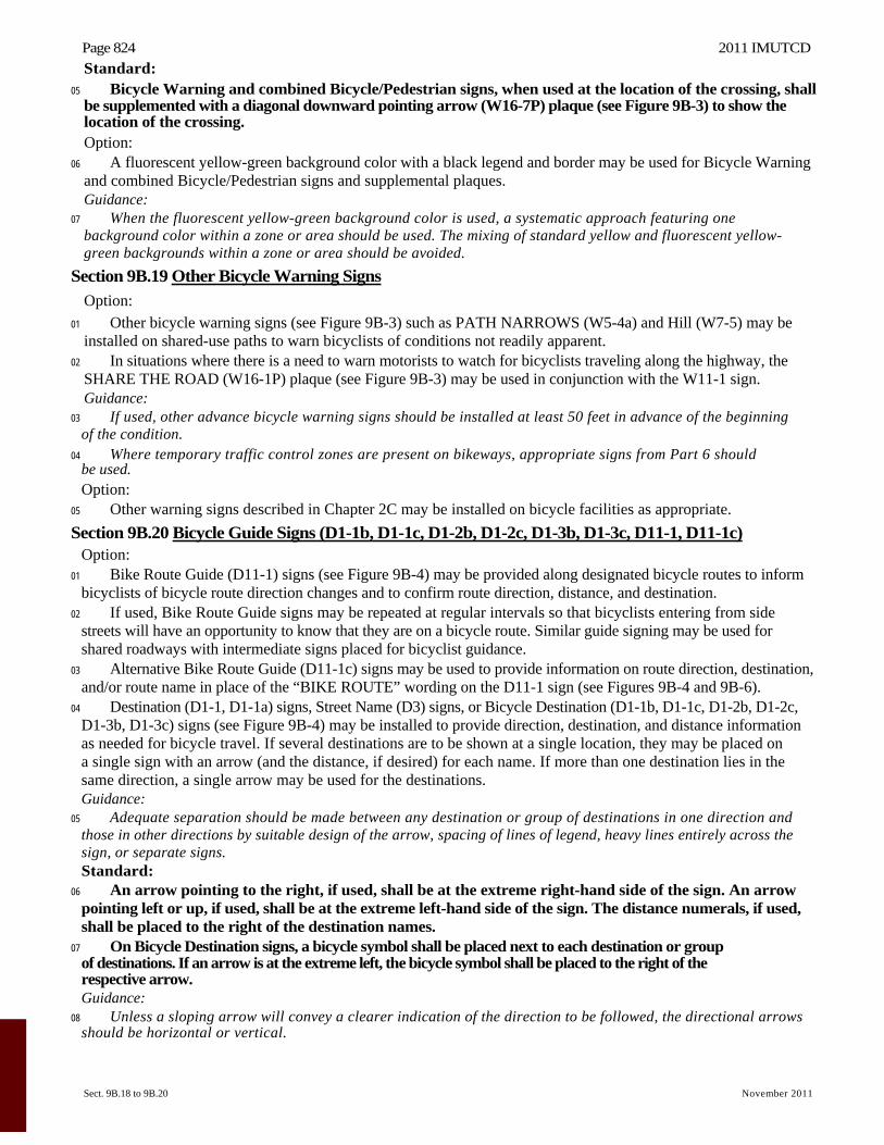
Standard: 05 Bicycle Warning and combined Bicycle/Pedestrian signs, when used at the location of the crossing, shall
be supplemented with a diagonal downward pointing arrow (W16-7P) plaque (see Figure 9B-3) to show the location of the crossing. Option:
06 A fluorescent yellow-green background color with a black legend and border may be used for Bicycle Warning and combined Bicycle/Pedestrian signs and supplemental plaques. Guidance:
07 When the fluorescent yellow-green background color is used, a systematic approach featuring one background color within a zone or area should be used. The mixing of standard yellow and fluorescent yellow- green backgrounds within a zone or area should be avoided.
Section 9B.19 Other Bicycle Warning Signs
Option:
01 Other bicycle warning signs (see Figure 9B-3) such as PATH NARROWS (W5-4a) and Hill (W7-5) may be installed on shared-use paths to warn bicyclists of conditions not readily apparent.
02 In situations where there is a need to warn motorists to watch for bicyclists traveling along the highway, the SHARE THE ROAD (W16-1P) plaque (see Figure 9B-3) may be used in conjunction with the W11-1 sign. Guidance:
03 If used, other advance bicycle warning signs should be installed at least 50 feet in advance of the beginning of the condition.
04 Where temporary traffic control zones are present on bikeways, appropriate signs from Part 6 should be used. Option:
05 Other warning signs described in Chapter 2C may be installed on bicycle facilities as appropriate.
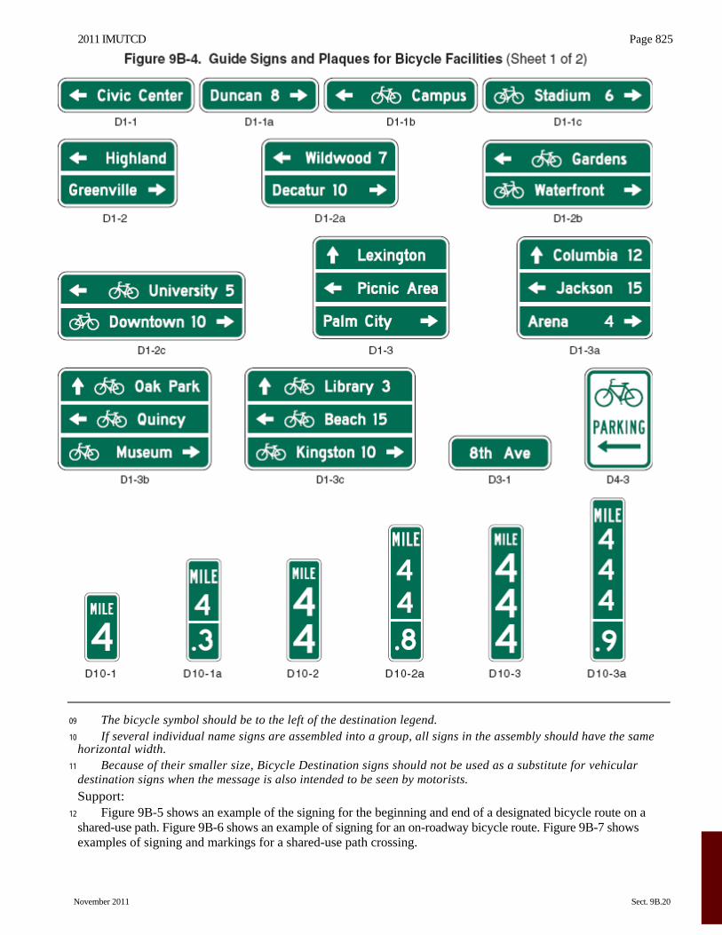
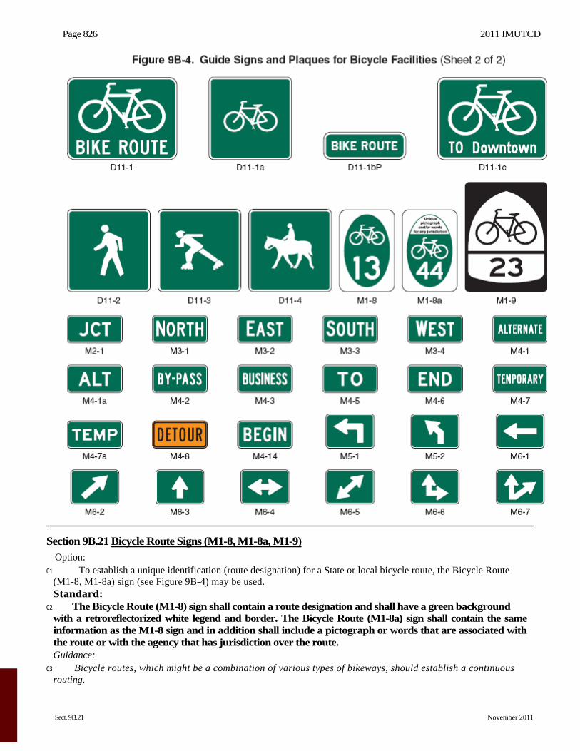
Section 9B.20 Bicycle Guide Signs (D1-1b, D1-1c, D1-2b, D1-2c, D1-3b, D1-3c, D11-1, D11-1c) Option:
01 Bike Route Guide (D11-1) signs (see Figure 9B-4) may be provided along designated bicycle routes to inform bicyclists of bicycle route direction changes and to confirm route direction, distance, and destination.
02 If used, Bike Route Guide signs may be repeated at regular intervals so that bicyclists entering from side streets will have an opportunity to know that they are on a bicycle route. Similar guide signing may be used for shared roadways with intermediate signs placed for bicyclist guidance.
03 Alternative Bike Route Guide (D11-1c) signs may be used to provide information on route direction, destination, and/or route name in place of the “BIKE ROUTE” wording on the D11-1 sign (see Figures 9B-4 and 9B-6).
04 Destination (D1-1, D1-1a) signs, Street Name (D3) signs, or Bicycle Destination (D1-1b, D1-1c, D1-2b, D1-2c, D1-3b, D1-3c) signs (see Figure 9B-4) may be installed to provide direction, destination, and distance information as needed for bicycle travel. If several destinations are to be shown at a single location, they may be placed on a single sign with an arrow (and the distance, if desired) for each name. If more than one destination lies in the same direction, a single arrow may be used for the destinations. Guidance:
05 Adequate separation should be made between any destination or group of destinations in one direction and those in other directions by suitable design of the arrow, spacing of lines of legend, heavy lines entirely across the sign, or separate signs. Standard:
06 An arrow pointing to the right, if used, shall be at the extreme right-hand side of the sign. An arrow pointing left or up, if used, shall be at the extreme left-hand side of the sign. The distance numerals, if used, shall be placed to the right of the destination names.
07 On Bicycle Destination signs, a bicycle symbol shall be placed next to each destination or group of destinations. If an arrow is at the extreme left, the bicycle symbol shall be placed to the right of the respective arrow. Guidance:
08 Unless a sloping arrow will convey a clearer indication of the direction to be followed, the directional arrows should be horizontal or vertical.
2011 IMUTCD Page 825
November 2011 Sect. 9B.20
09 The bicycle symbol should be to the left of the destination legend. 10 If several individual name signs are assembled into a group, all signs in the assembly should have the same
horizontal width. 11 Because of their smaller size, Bicycle Destination signs should not be used as a substitute for vehicular
destination signs when the message is also intended to be seen by motorists. Support:
12 Figure 9B-5 shows an example of the signing for the beginning and end of a designated bicycle route on a shared-use path. Figure 9B-6 shows an example of signing for an on-roadway bicycle route. Figure 9B-7 shows examples of signing and markings for a shared-use path crossing.
Page 826 2011 IMUTCD
Sect. 9B.21 November 2011
Section 9B.21 Bicycle Route Signs (M1-8, M1-8a, M1-9) Option:
01 To establish a unique identification (route designation) for a State or local bicycle route, the Bicycle Route (M1-8, M1-8a) sign (see Figure 9B-4) may be used. Standard:
02 The Bicycle Route (M1-8) sign shall contain a route designation and shall have a green background with a retroreflectorized white legend and border. The Bicycle Route (M1-8a) sign shall contain the same information as the M1-8 sign and in addition shall include a pictograph or words that are associated with the route or with the agency that has jurisdiction over the route. Guidance:
03 Bicycle routes, which might be a combination of various types of bikeways, should establish a continuous routing.
2011 IMUTCD Page 827
November 2011 Sect. 9B.21
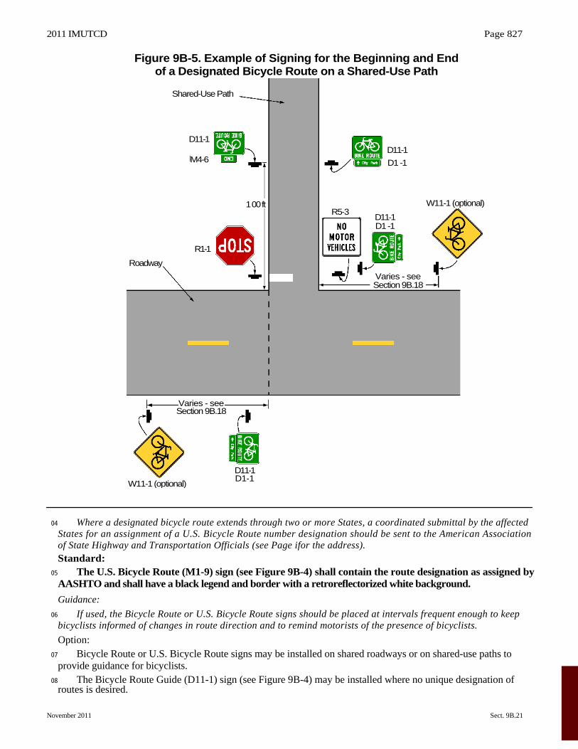
Figure 9B-5. Example of Signing for the Beginning and End of a Designated Bicycle Route on a Shared-Use Path
04 Where a designated bicycle route extends through two or more States, a coordinated submittal by the affected States for an assignment of a U.S. Bicycle Route number designation should be sent to the American Association of State Highway and Transportation Officials (see Page ifor the address). Standard:
05 The U.S. Bicycle Route (M1-9) sign (see Figure 9B-4) shall contain the route designation as assigned by AASHTO and shall have a black legend and border with a retroreflectorized white background.
Guidance:
06 If used, the Bicycle Route or U.S. Bicycle Route signs should be placed at intervals frequent enough to keep bicyclists informed of changes in route direction and to remind motorists of the presence of bicyclists.
Option: 07 Bicycle Route or U.S. Bicycle Route signs may be installed on shared roadways or on shared-use paths to
provide guidance for bicyclists. 08 The Bicycle Route Guide (D11-1) sign (see Figure 9B-4) may be installed where no unique designation of
routes is desired.
W11-1 (optional)
D11-1D1-1
Varies - see Section 9B.18
Roadway
Shared-Use Path
D11-1
M4-6
R1-1
1 00 ftR5-3
Varies - see Section 9B.18
D11-1D1-1
D11-1
D1 -1
W11-1 (optional)
Page 828 2011 IMUTCD
Sect. 9B.22 November 2011
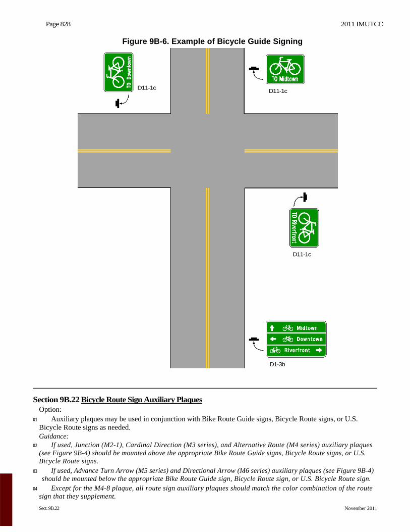
Figure 9B-6. Example of Bicycle Guide Signing
Section 9B.22 Bicycle Route Sign Auxiliary Plaques Option:
01 Auxiliary plaques may be used in conjunction with Bike Route Guide signs, Bicycle Route signs, or U.S. Bicycle Route signs as needed. Guidance:
02 If used, Junction (M2-1), Cardinal Direction (M3 series), and Alternative Route (M4 series) auxiliary plaques (see Figure 9B-4) should be mounted above the appropriate Bike Route Guide signs, Bicycle Route signs, or U.S. Bicycle Route signs.
03 If used, Advance Turn Arrow (M5 series) and Directional Arrow (M6 series) auxiliary plaques (see Figure 9B-4) should be mounted below the appropriate Bike Route Guide sign, Bicycle Route sign, or U.S. Bicycle Route sign.
04 Except for the M4-8 plaque, all route sign auxiliary plaques should match the color combination of the route sign that they supplement.
D11-1cD11-1c
D11-1c
D1-3b
2011 IMUTCD Page 829
November 2011 Sect. 9B.22
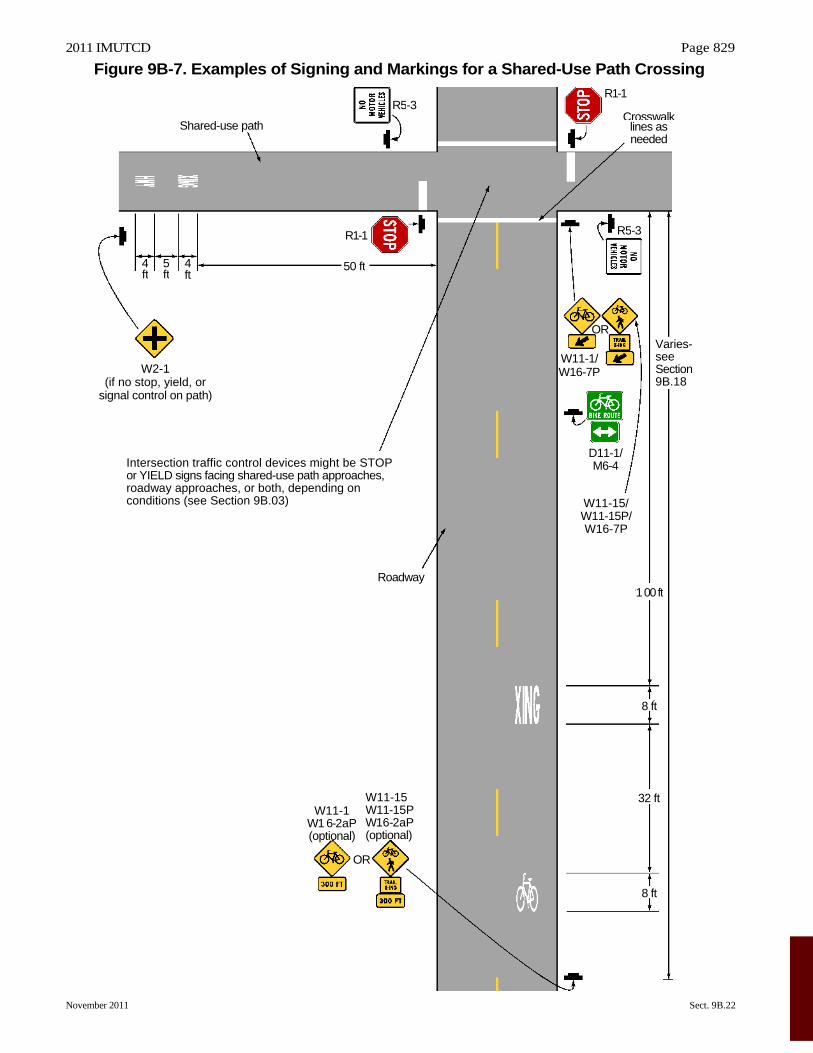
Figure 9B-7. Examples of Signing and Markings for a Shared-Use Path Crossing
W2-1 (if no stop, yield, or
signal control on path)
Intersection traffic control devices might be STOP or YIELD signs facing shared-use path approaches, roadway approaches, or both, depending on conditions (see Section 9B.03)
4 ft
5 ft
Shared-use path
4ft
W11-1W1 6-2aP(optional)
50 ft
R1-1
OR
W11-15 W11-15PW16-2aP (optional)
Roadway
R5-3
W16-7P W11-1/
W11-15/ W11-15P/ W16-7P
D11-1/
OR
M6-4
R1-1
R5-3
Crosswalklines asneeded
1 00 ft
32 ft
8 ft
8 ft
Varies-see Section 9B.18
Page 830 2011 IMUTCD
Sect. 9B.22 to 9B.24 November 2011
05 Route sign auxiliary plaques carrying word legends that are used on bicycle routes should have a minimum size of 12 x 6 inches. Route sign auxiliary plaques carrying arrow symbols that are used on bicycle routes should have a minimum size of 12 x 9 inches. Option:
06 With route signs of larger sizes, auxiliary plaques may be suitably enlarged, but not such that they exceed the width of the route sign.
07 A route sign and any auxiliary plaques used with it may be combined on a single sign. 08 Destination (D1-1b and D1-1c) signs (see Figure 9B-4) may be mounted below Bike Route Guide signs, Bicycle
Route signs, or U.S. Bicycle Route signs to furnish additional information, such as directional changes in the route, or intermittent distance and destination information.
Section 9B.23 Bicycle Parking Area Sign (D4-3) Option:
01 The Bicycle Parking Area (D4-3) sign (see Figure 9B-4) may be installed where it is desirable to show the direction to a designated bicycle parking area. The arrow may be reversed as appropriate. Standard:
02 The legend and border of the Bicycle Parking Area sign shall be green on a retroreflectorized white background.
Section 9B.24 Reference Location Signs (D10-1 through D10-3) and Intermediate Reference Location Signs (D10-1a through D10-3a)
Support: 01 There are two types of reference location signs:
A. Reference Location (D10-1, 2, and 3) signs show an integer distance point along a shared-use path; and B. Intermediate Reference Location (D10-1a, 2a, and 3a) signs also show a decimal between integer distance
points along a shared-use path. Option:
02 Reference Location (D10-1 to D10-3) signs (see Figure 9B-4) may be installed along any section of a shared- use path to assist users in estimating their progress, to provide a means for identifying the location of emergency incidents and crashes, and to aid in maintenance and servicing.
03 To augment the reference location sign system, Intermediate Reference Location (D10-1a to D10-3a) signs (see Figure 9B-4), which show the tenth of a mile with a decimal point, may be installed at one tenth of a mile intervals, or at some other regular spacing. Standard:
04 If Intermediate Reference Location (D10-1a to D10-3a) signs are used to augment the reference location sign system, the reference location sign at the integer mile point shall display a decimal point and a zero numeral.
05 If placed on shared-use paths, reference location signs shall contain 4.5-inch white numerals on a green background that is at least 6 inches wide with a white border. The signs shall contain the word MILE in 2.25-inch white letters.
06 Reference location signs shall have a minimum mounting height of 2 feet, measured vertically from the bottom of the sign to the elevation of the near edge of the shared-use path, and shall not be governed by the mounting height requirements prescribed in Section 9B.01. Option:
07 Reference location signs may be installed on one side of the shared-use path only and may be installed back-to-back.
08 If a reference location sign cannot be installed in the correct location, it may be moved in either direction as much as 50 feet. Guidance:
09 If a reference location sign cannot be placed within 50 feet of the correct location, it should be omitted. 10 Zero distance should begin at the south and west terminus points of shared-use paths.
Support: 11 Section 2H.05 contains additional information regarding reference location signs.
2011 IMUTCD Page 831
November 2011 Sect. 9B.25 to 9B.26
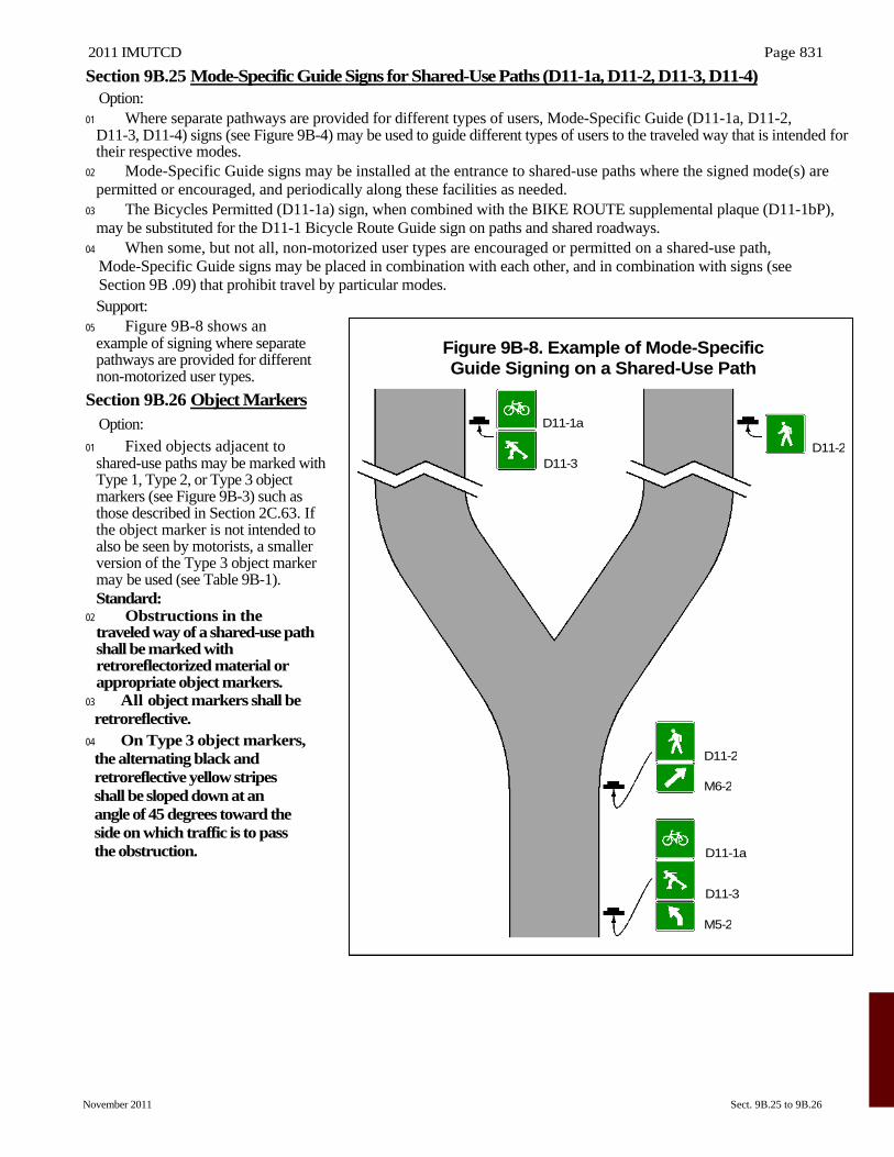
Section 9B.25 Mode-Specific Guide Signs for Shared-Use Paths (D11-1a, D11-2, D11-3, D11-4) Option:
01 Where separate pathways are provided for different types of users, Mode-Specific Guide (D11-1a, D11-2, D11-3, D11-4) signs (see Figure 9B-4) may be used to guide different types of users to the traveled way that is intended for their respective modes.
02 Mode-Specific Guide signs may be installed at the entrance to shared-use paths where the signed mode(s) are permitted or encouraged, and periodically along these facilities as needed.
03 The Bicycles Permitted (D11-1a) sign, when combined with the BIKE ROUTE supplemental plaque (D11-1bP), may be substituted for the D11-1 Bicycle Route Guide sign on paths and shared roadways.
04 When some, but not all, non-motorized user types are encouraged or permitted on a shared-use path, Mode-Specific Guide signs may be placed in combination with each other, and in combination with signs (see Section 9B .09) that prohibit travel by particular modes. Support:
05 Figure 9B-8 shows an example of signing where separate pathways are provided for different non-motorized user types.
Section 9B.26 Object Markers Option:
01 Fixed objects adjacent to shared-use paths may be marked with Type 1, Type 2, or Type 3 object markers (see Figure 9B-3) such as those described in Section 2C.63. If the object marker is not intended to also be seen by motorists, a smaller version of the Type 3 object marker may be used (see Table 9B-1). Standard:
02 Obstructions in the traveled way of a shared-use path shall be marked with retroreflectorized material or appropriate object markers.
03 All object markers shall be retroreflective.
04 On Type 3 object markers, the alternating black and retroreflective yellow stripes shall be sloped down at an angle of 45 degrees toward the side on which traffic is to pass the obstruction.
Figure 9B-8. Example of Mode-SpecificGuide Signing on a Shared-Use Path
D11-1a
D11-3
D11-2
M6-2
D11-1a
D11-3
M5-2
D11-2
Page 832 2011 IMUTCD
Sect. 9C.01 to 9C.04 November 2011
CHAPTER 9C. MARKINGS
Section 9C.01 Functions of Markings
Support: 01 Markings indicate the separation of the lanes for road users, assist the bicyclist by indicating assigned travel
paths, indicate correct position for traffic control signal actuation, and provide advance information for turning and crossing maneuvers.
Section 9C.02 General Principles Guidance:
01 Bikeway design guides (see Section 9A.05) should be used when designing markings for bicycle facilities. Standard:
02 Markings used on bikeways shall be retroreflectorized. Guidance:
03 Pavement marking word messages, symbols, and/or arrows should be used in bikeways where appropriate. Consideration should be given to selecting pavement marking materials that will minimize loss of traction for bicycles under wet conditions. Standard:
04 The colors, width of lines, patterns of lines, symbols, and arrows used for marking bicycle facilities shall be as defined in Sections 3A.05, 3A.06, and 3B.20. Support:
05 Figures 9B-7 and 9C-1 through 9C-9 show examples of the application of lines, word messages, symbols, and arrows on designated bikeways. Option:
06 A dotted line may be used to define a specific path for a bicyclist crossing an intersection (see Figure 9C-1) as described in Sections 3A.06 and 3B.08.
Section 9C.03 Marking Patterns and Colors on Shared-Use Paths Option:
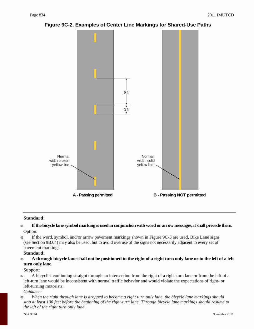
01 Where shared-use paths are of sufficient width to designate two minimum width lanes, a solid yellow line may be used to separate the two directions of travel where passing is not permitted, and a broken yellow line may be used where passing is permitted (see Figure 9C-2). Guidance:
02 Broken lines used on shared-use paths should have the usual 1-to-3 segment-to-gap ratio. A nominal 3-foot segment with a 9-foot gap should be used.
03 If conditions make it desirable to separate two directions of travel on shared-use paths at particular locations, a solid yellow line should be used to indicate no passing and no traveling to the left of the line.
04 Markings as shown in Figure 9C-8 should be used at the location of obstructions in the center of the path, including vertical elements intended to physically prevent unauthorized motor vehicles from entering the path. Option:
05 A solid white line may be used on shared-use paths to separate different types of users. The R9-7 sign (see Section 9B.12) may be used to supplement the solid white line.
06 Smaller size letters and symbols may be used on shared-use paths. Where arrows are needed on shared-use paths, half-size layouts of the arrows may be used (see Section 3B.20).
Section 9C.04 Markings For Bicycle Lanes Support:
01 Pavement markings designate that portion of the roadway for preferential use by bicyclists. Markings inform all road users of the restricted nature of the bicycle lane. Standard:
02 Longitudinal pavement markings shall be used to define bicycle lanes. Guidance:
03 If used, bicycle lane word, symbol, and/or arrow markings (see Figure 9C-3) should be placed at the beginning of a bicycle lane and at periodic intervals along the bicycle lane based on engineering judgment.
2011 IMUTCD Page 833
November 2011 Sect. 9C.04
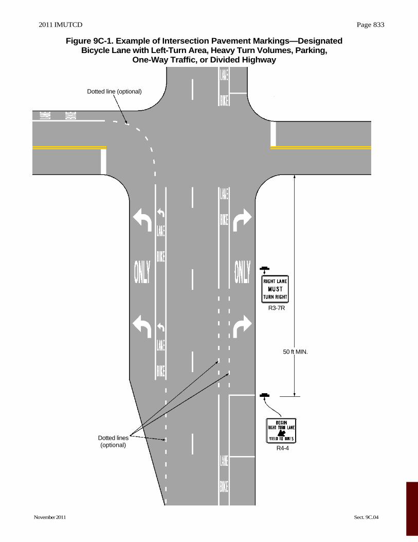
Figure 9C-1. Example of Intersection Pavement Markings—Designated Bicycle Lane with Left-Turn Area, Heavy Turn Volumes, Parking,
One-Way Traffic, or Divided Highway
Dotted line (optional)
Dotted lines (optional)
R3-7R
R4-4
50 ft MIN.
Page 834 2011 IMUTCD
Sect. 9C.04 November 2011
Figure 9C-2. Examples of Center Line Markings for Shared-Use Paths
A - Passing permitted B - Passing NOT permitted
Standard:
04 If the bicycle lane symbol marking is used in conjunction with word or arrow messages, it shall precede them. Option:
05 If the word, symbol, and/or arrow pavement markings shown in Figure 9C-3 are used, Bike Lane signs (see Section 9B.04) may also be used, but to avoid overuse of the signs not necessarily adjacent to every set of pavement markings. Standard:
06 A through bicycle lane shall not be positioned to the right of a right turn only lane or to the left of a left turn only lane. Support:
07 A bicyclist continuing straight through an intersection from the right of a right-turn lane or from the left of a left-turn lane would be inconsistent with normal traffic behavior and would violate the expectations of right- or left-turning motorists. Guidance:
08 When the right through lane is dropped to become a right turn only lane, the bicycle lane markings should stop at least 100 feet before the beginning of the right-turn lane. Through bicycle lane markings should resume to the left of the right turn only lane.
9 ft
3 ft
Normalwidth broken
yellow line
Normal width solidyellow line
2011 IMUTCD Page 835
November 2011 Sect. 9C.04
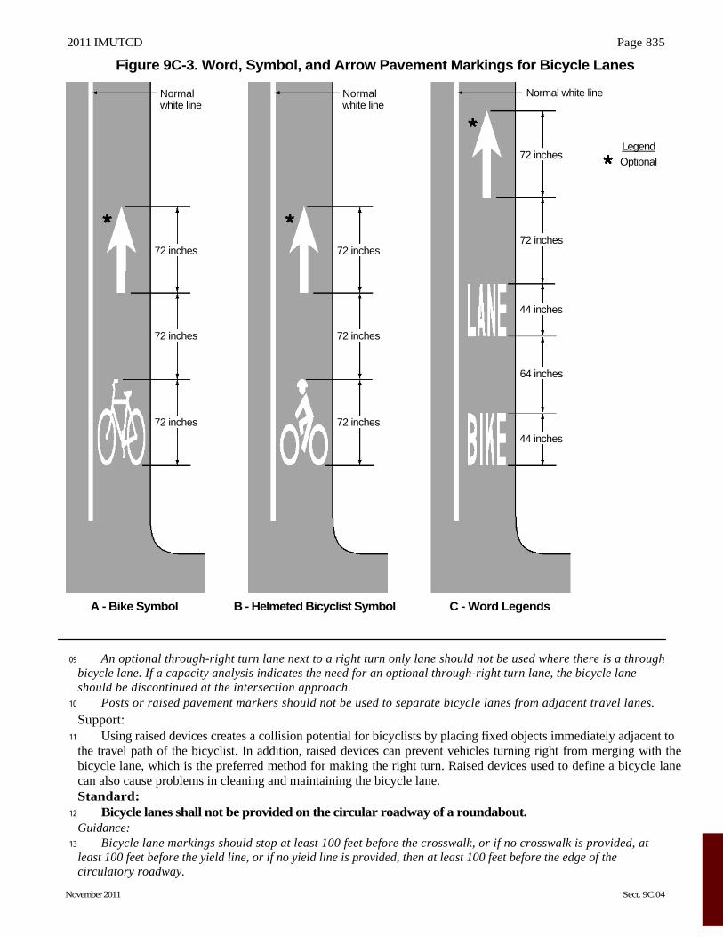
Figure 9C-3. Word, Symbol, and Arrow Pavement Markings for Bicycle Lanes
09 An optional through-right turn lane next to a right turn only lane should not be used where there is a through bicycle lane. If a capacity analysis indicates the need for an optional through-right turn lane, the bicycle lane should be discontinued at the intersection approach.
10 Posts or raised pavement markers should not be used to separate bicycle lanes from adjacent travel lanes. Support:
11 Using raised devices creates a collision potential for bicyclists by placing fixed objects immediately adjacent to the travel path of the bicyclist. In addition, raised devices can prevent vehicles turning right from merging with the bicycle lane, which is the preferred method for making the right turn. Raised devices used to define a bicycle lane can also cause problems in cleaning and maintaining the bicycle lane. Standard:
12 Bicycle lanes shall not be provided on the circular roadway of a roundabout. Guidance:
13 Bicycle lane markings should stop at least 100 feet before the crosswalk, or if no crosswalk is provided, at least 100 feet before the yield line, or if no yield line is provided, then at least 100 feet before the edge of the circulatory roadway.
A - Bike Symbol B - Helmeted Bicyclist Symbol C - Word Legends
72 inches
72 inches
72 inches
Normal white line
72 inches
72 inches
72 inches
Normal white line
Normal white line
72 inches
72 inches
44 inches
64 inches
44 inches
Legend
Optional
Page 836 2011 IMUTCD
Sect. 9C.04 to 9C.07 November 2011
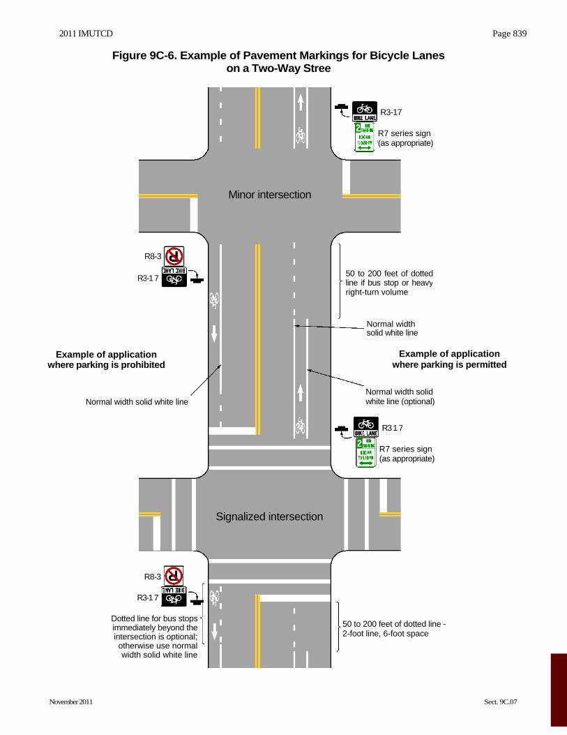
Support: 14 Examples of bicycle lane markings at right-turn lanes are shown in Figures 9C-1, 9C-4, and 9C-5. Examples
of pavement markings for bicycle lanes on a two-way street are shown in Figure 9C-6. Pavement word message, symbol, and arrow markings for bicycle lanes are shown in Figure 9C-3.
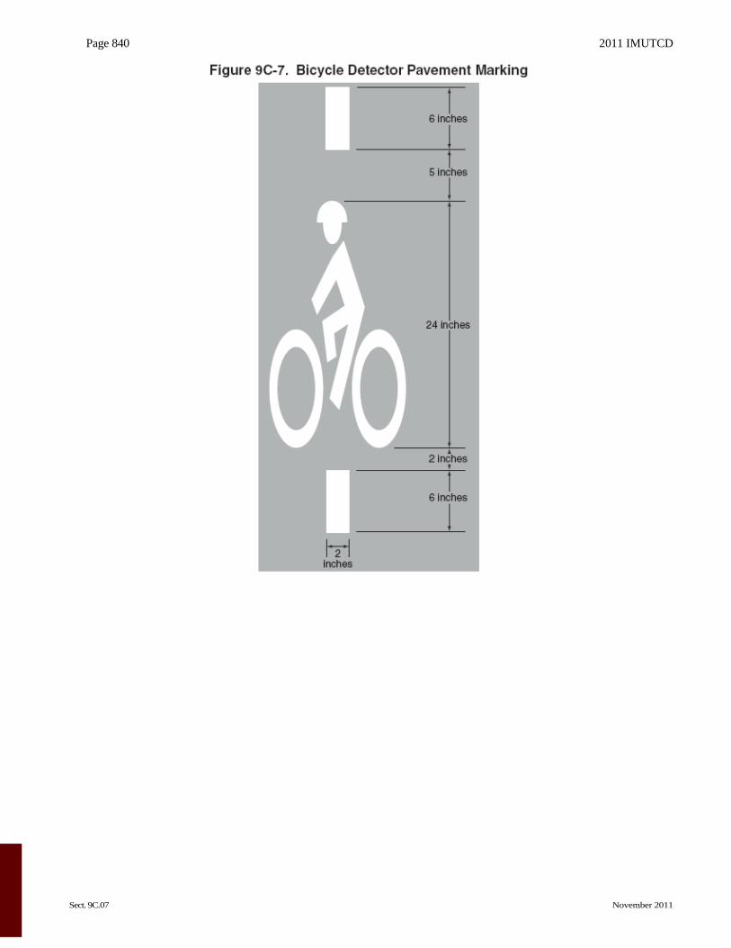
Section 9C.05 Bicycle Detector Symbol Option:
01 A symbol (see Figure 9C-7) may be placed on the pavement indicating the optimum position for a bicyclist to actuate the signal.
02 An R10-22 sign (see Section 9B.13 and Figure 9B-2) may be installed to supplement the pavement marking.
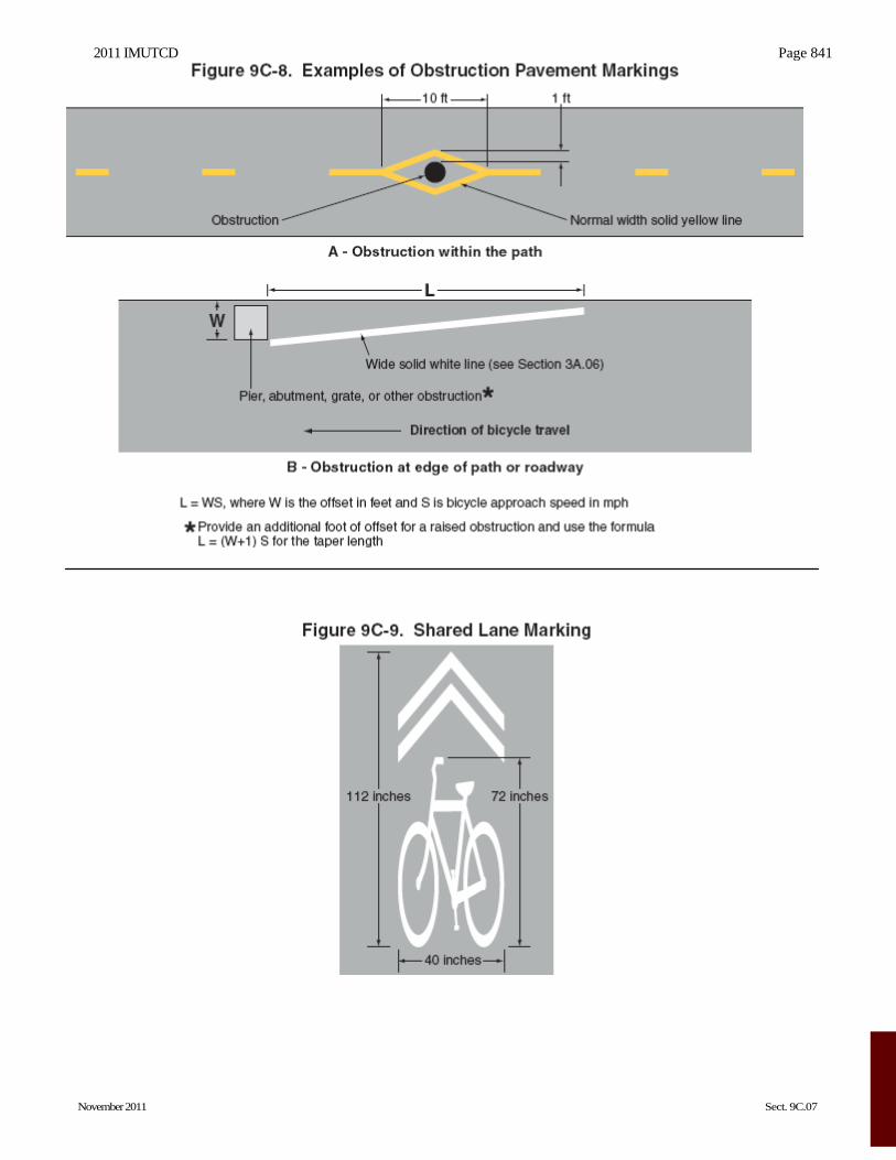
Section 9C.06 Pavement Markings for Obstructions Guidance:
01 In roadway situations where it is not practical to eliminate a drain grate or other roadway obstruction that is inappropriate for bicycle travel, white markings applied as shown in Figure 9C-8 should be used to guide bicyclists around the condition.
Section 9C.07 Shared Lane Marking Option:
01 The Shared Lane Marking shown in Figure 9C-9 may be used to: A. Assist bicyclists with lateral positioning in a shared lane with on-street parallel parking in order to reduce
the chance of a bicyclist’s impacting the open door of a parked vehicle, B. Assist bicyclists with lateral positioning in lanes that are too narrow for a motor vehicle and a bicycle to
travel side by side within the same traffic lane, C. Alert road users of the lateral location bicyclists are likely to occupy within the traveled way, D. Encourage safe passing of bicyclists by motorists, and E. Reduce the incidence of wrong-way bicycling.
Guidance: 02 The Shared Lane Marking should not be placed on roadways that have a speed limit above 35 mph.
Standard:
03 Shared Lane Markings shall not be used on shoulders or in designated bicycle lanes. Guidance:
04 If used in a shared lane with on-street parallel parking, Shared Lane Markings should be placed so that the centers of the markings are at least 11 feet from the face of the curb, or from the edge of the pavement where there is no curb.
05 If used on a street without on-street parking that has an outside travel lane that is less than 14 feet wide, the centers of the Shared Lane Markings should be at least 4 feet from the face of the curb, or from the edge of the pavement where there is no curb.
06 If used, the Shared Lane Marking should be placed immediately after an intersection and spaced at intervals not greater than 250 feet thereafter. Option:
07 Section 9B.06 describes a Bicycles May Use Full Lane sign that may be used in addition to or instead of the Shared Lane Marking to inform road users that bicyclists might occupy the travel lane.
2011 IMUTCD Page 837
November 2011 Sect. 9C.07
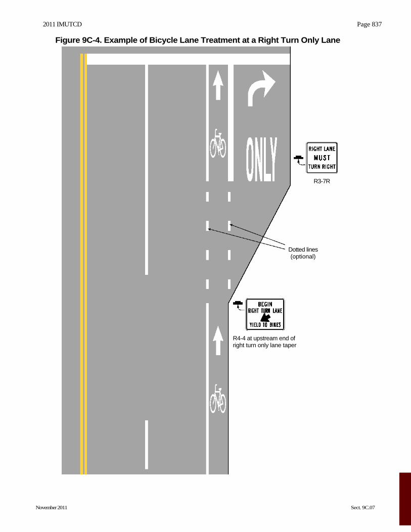
Figure 9C-4. Example of Bicycle Lane Treatment at a Right Turn Only Lane
R3-7R
Dotted lines (optional)
R4-4 at upstream end of right turn only lane taper
Page 838 2011 IMUTCD
Sect. 9C.07 November 2011
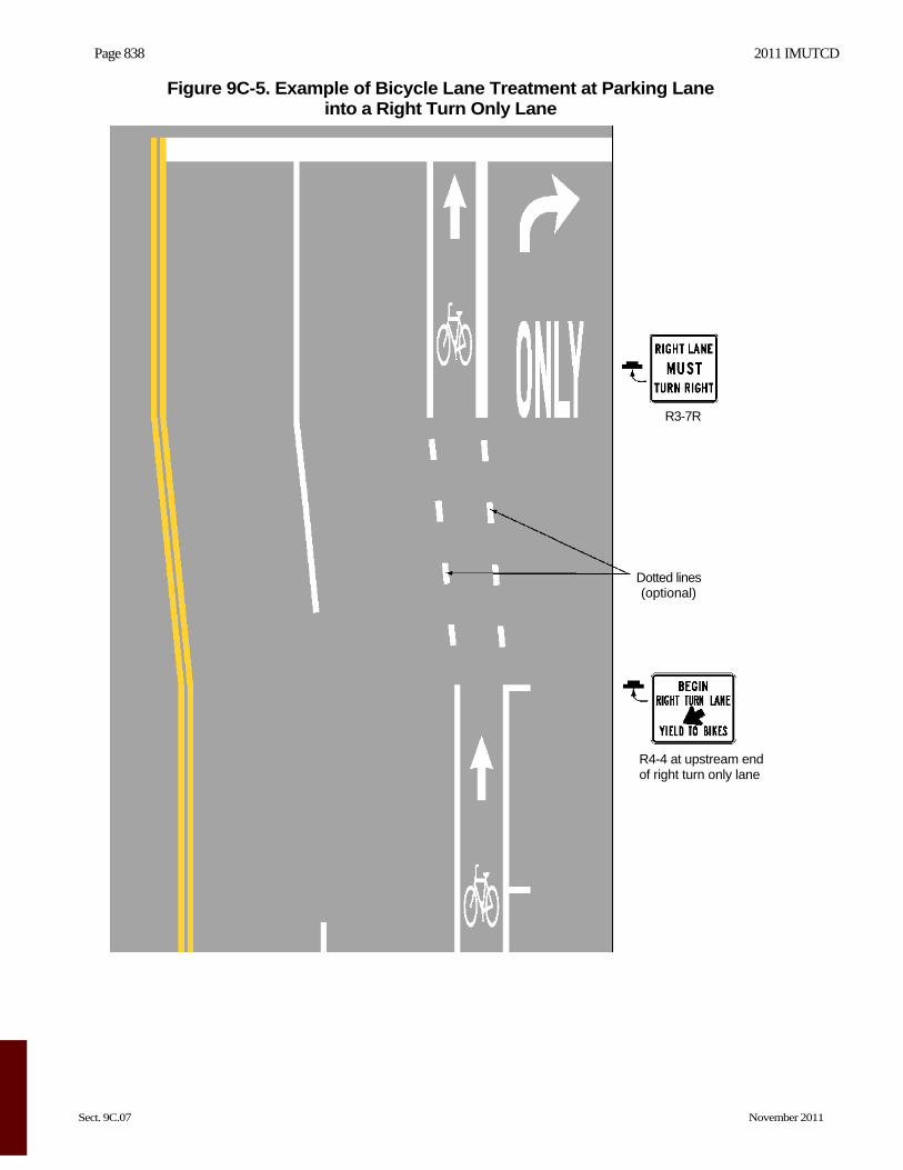
Figure 9C-5. Example of Bicycle Lane Treatment at Parking Lane into a Right Turn Only Lane
R3-7R
Dotted lines (optional)
R4-4 at upstream end of right turn only lane
2011 IMUTCD Page 839
November 2011 Sect. 9C.07
Figure 9C-6. Example of Pavement Markings for Bicycle Lanes on a Two-Way Stree
Example of application where parking is prohibited
Normal width solid white line
Dotted line for bus stopsimmediately beyond theintersection is optional;otherwise use normalwidth solid white line
R3-1 7
R3-1 7
R8-3
R8-3
Signalized intersection
Minor intersection
50 to 200 feet of dotted line - 2-foot line, 6-foot space
50 to 200 feet of dottedline if bus stop or heavyright-turn volume
Normal width solid white line (optional)
Normal width solid white line
R7 series sign (as appropriate)
R7 series sign (as appropriate)
R3-17
R3 1 7
Example of application where parking is permitted
Page 840 2011 IMUTCD
Sect. 9C.07 November 2011
2011 IMUTCD Page 841
November 2011 Sect. 9C.07
Page 842 2011 IMUTCD
Sect. 9D.01 to 9D.02 November 2011
CHAPTER 9D. SIGNALS
Section 9D.01 Application Support:
01 Part 4 contains information regarding signal warrants and other requirements relating to signal installations. Option:
02 For purposes of signal warrant evaluation, bicyclists may be counted as either vehicles or pedestrians.
Section 9D.02 Signal Operations for Bicycles Standard:
01 At installations where visibility-limited signal faces are used, signal faces shall be adjusted so bicyclists for whom the indications are intended can see the signal indications. If the visibility-limited signal faces cannot be aimed to serve the bicyclist, then separate signal faces shall be provided for the bicyclist.
02 On bikeways, signal timing and actuation shall be reviewed and adjusted to consider the needs of bicyclists.