Part 642 Specifications for Construction Contracts210-VI-NEH, January 2009) i Part 642...
488
(210-VI-NEH, January 2009) National Engineering Handbook Part 642 Specifications for Construction Contracts
Transcript of Part 642 Specifications for Construction Contracts210-VI-NEH, January 2009) i Part 642...
(210-VI-NEH, January 2009)
National Engineering Handbook
Part 642 Specifications for Construction Contracts

National Engineering HandbookSpecificationsPart 642
(210-VI-NEH, January 2009)
Originally issued May 2001First Revision issued November 2005Second Revision issued January 2009
The U.S. Department of Agriculture (USDA) prohibits discrimination in all its programs and activities on the basis of race, color, national origin, age, disability, and where applicable, sex, marital status, familial status, parental status, religion, sexual orientation, genetic information, political beliefs, reprisal, or because all or a part of an individual’s income is derived from any public assistance program. (Not all prohibited bases apply to all pro-grams.) Persons with disabilities who require alternative means for commu-nication of program information (Braille, large print, audiotape, etc.) should contact USDA’s TARGET Center at (202) 720-2600 (voice and TDD). To file a complaint of discrimination write to USDA, Director, Office of Civil Rights, 1400 Independence Avenue, S.W., Washington, D.C. 20250-9410 or call (800) 795-3272 (voice) or (202) 720-6382 (TDD). USDA is an equal opportunity provider and employer.

i(210-VI-NEH, January 2009)
Part 642 Specifications for Construction Contracts
Contents: Chapter 1 General Contract Specification Procedures
642.0100 General 1–1
(a) Nonfederal construction contract ................................................................1–1
(b) Federal construction contract .....................................................................1–1
(c) Purpose ...........................................................................................................1–1
642.0101 Terms and definitions 1–2
642.0102 Applicability 1–2
642.0103 National standard construction specifications 1–3
642.0104 National standard material specifications 1–3
642.0105 Selecting appropriate national standard specifications 1–4
642.0106 Interim specifications 1–4
642.0107 One-time-use specifications 1–5
642.0108 Bid schedule 1–6
(a) Designating the items of work ......................................................................1–6
(b) Division of the work into items ....................................................................1–6
(c) Numbering and titling ....................................................................................1–7
(d) Pay items .........................................................................................................1–7
642.0109 Contract specifications 1–8
(a) Compilation .....................................................................................................1–8
(b) Identifying .......................................................................................................1–8
(c) Measurement and payment ...........................................................................1–9
(d) Preparing construction details .....................................................................1–9
Examples Example 1–1 Typical bid schedule ..................................................................1–7
Example 1–2 Typical construction detail for a specific contract .............1–10
for excavation
Example 1–3 Typical construction detail to cross reference a .................1–14
subsidiary item
National Engineering HandbookSpecifications for Construction Contracts
Part 642
ii (210-VI-NEH, January 2009)
Chapter 2 National Standard Construction Specifications
- - - - - - - Effective date - - - - - - - - Instruction Specification
Site preparation 1—Clearing 1/09 5/01 2—Clearing and Grubbing 1/09 5/01 3—Structure Removal 1/09 5/01 4—Channel Clearing and Shaping 1/09 5/01 5—Pollution Control 1/09 1/09 6—Seeding, Sprigging, and Mulching 1/09 5/01 7—Construction Surveys 1/09 1/09 8—Mobilization and Demobilization 1/09 5/01 9—Traffic Control 1/09 5/01 10—Water for Construction 1/09 1/09
Foundation work 11—Removal of Water 1/09 5/01 12—Relief Wells 1/09 5/01 13—Piling 1/09 5/01 14—Pressure Grouting 1/09 5/01
Earthwork 21—Excavation 1/09 5/01 22—(Reserved) 23—Earthfill 1/09 1/09 24—Drainfill 1/09 5/01 25—Rockfill 1/09 5/01 26—Topsoiling 1/09 5/01 27—Diversions and Waterways 1/09 5/01 28—Lime Treated Earthfill 1/09 1/09 29—Soil-Cement 1/09 1/09
Concrete and reinforcement 31—Concrete for Major Structures 1/09 1/09 32—Structure Concrete 1/09 1/09 33—Shotcrete 1/09 1/09 34—Steel Reinforcement 1/09 1/09 35—Concrete Repair 1/09 1/09 36—Roller Compacted Concrete 1/09 1/09

iii
National Engineering HandbookSpecifications for Construction Contracts
Part 642
(210-VI-NEH, January 2009)
- - - - - - - Effective date - - - - - - - Instruction Specification
Nonmetal pipe conduits and drains 41—Reinforced Concrete Pressure Pipe Conduits 1/09 5/01 42—Concrete Pipe Conduits and Drains 1/09 5/01 43—Clay Pipe 1/09 5/01 44—Corrugated Polyethylene Pipe 1/09 1/09 45—Plastic Pipe 1/09 1/09 46—Tile Drains 1/09 11/05
Metal pipe conduits 51—Corrugated Metal Pipe 1/09 5/01 52—Steel Pipe 1/09 5/01 53—Ductile-Iron Pipe 1/09 5/01
Riprap and slope protection 61—Rock Riprap 1/09 1/09 62—Grouted Rock Riprap 1/09 5/01 63—Treatment of Rock Surfaces 1/09 5/01 64—Gabion Baskets and Mattresses 1/09 1/09
Water control gates and valves 71—Water Control Gates 1/09 5/01
Miscellaneous structural work 81—Metal Fabrication and Installation 1/09 5/01 82—Painting Metalwork 1/09 11/05 83—Timber Fabrication and Installation 1/09 1/09 84—Painting Wood 1/09 11/05Miscellaneous construction 91—Chain Link Fence 1/09 5/01 92—Field Fence 1/09 1/09 93—Identification Markers or Plaques 1/09 5/01 94—Contractor Quality Control 1/09 1/09 95—Geotextile 1/09 5/01 96—Field Office 1/09 5/01 97—Flexible Membrane Liner 1/09 11/05 98—Geosynthetic Clay Liner 1/09 11/05

National Engineering HandbookSpecifications for Construction Contracts
Part 642
iv (210-VI-NEH, January 2009)
Chapter 3 National Standard Material Specifications
Effective date
Foundation materials 511—Steel Piles 5/01 512—Wood Piles 5/01 513—Precast Concrete Piles 5/01 514—Cast-In-Place Concrete Piles With Shells 5/01
Aggregates and rock 521—Aggregates for Drainfill and Filters 5/01 522—Aggregates for Portland Cement Concrete 5/01 523—Rock for Riprap 11/05 524—Aggregates for Roller Compacted Concrete 11/05
Concrete materials 531—Portland Cement 5/01 532— Supplementary Cementitious Materials 1/09 533—Chemical Admixtures for Concrete 11/05 534—Concrete Curing Compound 1/09 535—Preformed Expansion Joint Filler 5/01 536—Sealing Compound for Joints in Concrete and Concrete Pipe 1/09 537—Nonmetallic Waterstops 5/01 538—Metal Waterstops 5/01 539—Steel Reinforcement (for concrete) 1/09
Nonmetal pipe and fittings 541—Reinforced Concrete Pressure Pipe 5/01 542—Concrete Culvert Pipe 11/05 543—Nonreinforced Concrete Pipe 5/01 544—Clay Pipe and Drain Tile 11/05 545—(Reserved) 546—(Reserved) 547—Plastic Pipe 1/09 548—Corrugated Polyethylene Pipe 1/09
Metal pipe and fittings 551—Coated Corrugated Steel Pipe 11/05 552—Aluminum Corrugated Pipe 5/01 553—Ductile-Iron Pipe 5/01 554—Steel Pipe 5/01
Water control gates and valves 571—Slide Gates 1/09 572—Flap Gates, Metal 1/09 573—Radial Gates 5/01

v
National Engineering HandbookSpecifications for Construction Contracts
Part 642
(210-VI-NEH, January 2009)
Effective date
Miscellaneous structural materials 581—Metal 11/05 582—Galvanizing 5/01 583—Coal Tar-Epoxy Paint 11/05 584—Structural Timber and Lumber 5/01 585—Wood Preservatives and Treatment 1/09
Miscellaneous construction materials 591—Field Fencing Material 1/09 592—Geotextile 1/09 593—Lime 11/05 594—Flexible Membrane Liner 1/09 595—Geosynthetic Clay Liner 11/05

National Engineering HandbookSpecifications for Construction Contracts
Part 642
(210-VI-NEH, January 2009)

(210–VI–NEH, January 2009) 1–1
Chapter 1 General Contract Specification Procedures
642.0100 General
(a) Non-Federal construction contract
The body of a non-Federal construction contract con-sists of the general provisions, bid schedule, specifica-tions, drawings, and, when applicable, special provi-sions and wage rate decisions. The general provisions are administrative and technical requirements that apply to all items of construction and to all contracts. In Natural Resources Conservation Service (NRCS) practice, these general provisions are furnished in a preprinted Form SCS-AS-43. The special provisions are administrative instructions and requirements that apply to the specific contract and are prepared by the responsible administrative office.
The bid schedule tabulates the items of work for which direct payment will be made, shows the estimat-ed quantities of work and the units of measurement, and provides space for the entry of contract prices. The specifications and drawings include the technical details and requirements of the contract. The office responsible for the design of the work develops the drawings and specifications and, in cooperation with the responsible administrative office, the bid schedule.
(b) Federal construction contract
The body of a Federal construction contract is assem-bled following the uniform contract format shown in Federal Acquisition Regulations (FAR) 14.201-1. Each section of an invitation for bids contains specific kinds of information for the contractor.
• SectionAistheStandardForm1442 Construction Contract cover sheet.
• SectionBisthebidscheduleasinnon-Federalcontract.
• SectionCisthespecificationsanddrawingsora reference to their attachment as Section J.
• SectionD,packaginginstructions,isusuallyblank.
• SectionsE,F,andGhavetheinspection,per-formance time, and contract administration data, respectively.
• SectionHisthemostsimilarsectiontothenon-Federal special provisions.
• SectionIistheboilerplate provisions common to all construction contracts. It may include most clauses by reference.
• SectionJisthelistofattachments.
• SectionsK,L,andMareinstructionsandcertifications necessary to complete the bid package properly. These three sections do not become part of the contract.
The technical specialist responsible for the design must work closely with the contracting officer to as-sure that the contract clauses are coordinated with the design requirements.
(c) Purpose
The purpose of Part 642, Specifications of the National Engineering Handbook (NEH) is to establish national standard construction and material specifications and procedures for developing interim and one-time-use specifications, preparing contract specifications, and bid schedules.

Part 642 National Engineering Handbook
General Contract Specification Procedures
Chapter 1
(210–VI–NEH, January 2009)1–2
642.0101 Terms and definitions
The following terms and definitions are established for use in all NRCS documents, publications, and corre-spondence relating to specifications for construction contracts:
National Standard Construction Specifications—State the technical and workmanship requirements for the various operations required in the construction of the works, the methods of measurement, and the basis of payment.
National Standard Material Specifications—State the quality of materials to be incorporated in the per-manent works.
Interim Specifications—Specifications prepared by States for use in contracts that include construction items or materials not covered by national standard specifications.
Standard Specifications—National standard and interim specifications.
Unique or One-Time-Use Specifications—Speci-fications for construction or material items that are unique to the contract and are not covered by national standard specifications or State interim specifications. The specifications are prepared within the State and intended for one-time-use only in a specific contract.
Construction Details—Prepared by the design office and state the special requirements peculiar to a spe-cific work of construction. They may take the form of written addenda to the standard construction specifi-cations or notes on the drawings.
Contract specifications—The complete specifica-tions prepared for a specific contract and consist of an assembly of appropriate standard and one-time-use specifications supplemented by lists and descriptions of items of work and construction details.
642.0102 Applicability
The national standard specifications in this handbook were prepared for use in construction work adminis-tered by NRCS. They were developed to
• ensureadherencetolawsandregulations,
• preventconflictswithinthespecificationsandbetween the specifications and other contract requirements,
• preventomissionofessentialelements,
• preventinclusionofextraneousmaterials,
• provideauniformbasisforinterpretation,and
• ensureuniformqualityofNRCSprojectworks.
NRCS policy on preparation and use of these specifica-tionsisintheNationalEngineeringManual,Part542,Specifications.
National standard specifications are prepared for con-struction operations and construction materials fre-quentlyrequiredinNRCSprojects.Nationalstandardconstruction specifications are in chapter 2 of this handbook. National standard material specifications are in chapter 3. These specifications will be modified bytheConservationEngineeringDivisionwheneveritappears appropriate to do so. Suggestions for changes, additions, deletions, or corrections should be submit-tedtotheDirectoroftheConservationEngineeringDivision.

Part 642 National Engineering Handbook
General Contract Specification Procedures
Chapter 1
(210–VI–NEH, January 2009) 1–3(210–VI–NEH, January 2009)
642.0103 National standard con-struction specifications
National standard construction specifications are to be used verbatim. Some national standard specifica-tions have sections that contain alternative methods of achieving work. The specification writer may delete the methods not used in the contract; however, the method selected must be used verbatim. Only methods identified in the specification may be deleted from the nationalstandardconstructionspecification.Detailson how to delete the methods and revise the section are included in the instructions.
Each of the construction specifications is supplement-ed by instructions for its use. These instructions state the applicability of the specification and describe the items of information that must be included in the con-tract specifications and drawings to completely define the specified item. They also give the conditions under which it may be appropriate to use any of the various methods listed. These supplementary instructions are included for use by design personnel and are not to be included in contract specifications.
All construction specification packages shall include Construction Specification 94, Contractor Quality Control. If single specifications are used for conserva-tion practices, Construction Specification 94 is recom-mended.
642.0104 National standard material specifications
National standard material specifications are prepared for those materials whose quality must be uniform in all areas of applicability. National standard material specifications are to be used verbatim. They are not supplemented by instructions for use. Items of infor-mation that must be included in the contract specifica-tions to completely describe the materials required for a specific contract are listed in the instructions for use of the construction specifications to which the mate-rial specifications are complementary.
Reference to material specifications may be in the na-tional standard construction specifications or may be placed in the construction details (either written in the specifications or noted on the contract drawings).

Part 642 National Engineering Handbook
General Contract Specification Procedures
Chapter 1
(210–VI–NEH, January 2009)1–4
642.0105 Selecting appropriate national standard specifications
The type of work to be done or the type of structural detail required often dictates the construction method or sequence. The specification requirements must be compatible with the methods that must be used. The specification writer must also make sure that the methods selected in one specification are compat-iblewiththoseselectedinanother.Forexample,themethodofdesignatingpaylimitsforexcavationandearthfill.
642.0106 Interim specifications
States may prepare interim specifications for use in their State for items not covered by national stan-dard construction and material specifications (such as methods or materials unique to a given locality) if there is a recurring need. Interim specifications are not to be developed if an industry standard is available, OMBA119.
Interim construction specifications must:
• Conformtotheformatofthenationalstandardconstruction specifications.
• Benumberedconsecutivelystartingwithnumber 200 and be dated and identified. In-terim construction specifications prepared by the former National Technical Centers (NTC's) that continue to have application need to be adapted as a State interim and numbered ac-cordingly.
• Containtermsanddefinitionsthatarecompat-ible with those used in the national standard construction specifications.
• Beconciseandfreefromambiguousclauses.
• Containmeasurementandpaymentclauseswritten in the same manner as those in the national standard construction specifications.
Interim construction specifications are to be used ver-batim. Some interim specifications have sections that contain alternative methods of achieving work. The specification author may delete the methods not used in the contract; however, the method selected must be used verbatim. Only methods identified in the specifi-cation may be deleted from the interim construction specification.Detailsonhowtodeletethemethodsand revise the section are included in the instructions.

Part 642 National Engineering Handbook
General Contract Specification Procedures
Chapter 1
(210–VI–NEH, January 2009) 1–5
Interim material specifications must:
• Conformtotheformatofthenational standard material specifications.
• Benumberedconsecutivelystartingwiththenumber 300 for States and be dated and identi-fied.Materialspecificationspreparedbytheformer NTC's that continue to have application need to be adapted by the State and numbered accordingly.
• DescribematerialsbyreferencetoAmericanSocietyforTestingandMaterials(ASTM)andother accepted reference standards and specifi-cations.
• Interimmaterialspecificationsaretobeusedverbatim.
The geographical area of application of each interim construction or material specification must be identi-fied at the lower left corner of each page of the specifi-cation. The identifying symbol should consist of NRCS anddatefollowedbytheStateabbreviationandproj-ect name:
NRCS – 12/99OK–WhiteCloud#2
States are to review and concur with all interim speci-fications when conducting peer reviews for designs conducted by another State. For Class VIII engineering designapprovallevelprojects,interimspecificationsneed to be submitted and identified when transmitting totheDirectoroftheConservationEngineeringDivi-sionforreview.WhenthespecificationforamaterialcoveredbyanexistingASTMorotheracceptedspeci-fication or standard has requirements other than those includedintheexistingspecificationorstandard,theengineering staff that prepared the specification shall prepareawrittenjustificationforthedeviation.ThisjustificationissubmittedwiththespecificationtotheState that will conduct the peer review.
Interim specifications that are technically sound and have proven to be national in scope will be considered for inclusion in the national standard construction and material specifications.
642.0107 One-time-use specifi-cations
Unique or one-time-use specifications are prepared for construction work or construction materials not covered by standard specifications and are for one-time-use in a specific contract. These specifications shall be approved before their use by the state conser-vation engineer. If such one-time-use specifications are later considered for adoption as interim specifications, they shall be submitted for approval according to the procedures prescribed for review of interim specifica-tions. One-time-use specifications shall be formatted according to the national standard specifications. They shall be numbered in the 400's for construction specifi-cations and in the 600's for material specifications. The conditions and requirements for interim specifications are also applicable to one-time-use specifications.

Part 642 National Engineering Handbook
General Contract Specification Procedures
Chapter 1
(210–VI–NEH, January 2009)1–6
642.0108 Bid schedule
The bid schedule forms the basis for payments to the contractor and must list all items of work for which di-rect payment will be made. Since the efficiency of con-tract administration is directly affected by the manner in which the schedule is organized, the preparation of the bid schedule requires the close cooperation of the responsible design engineer and the contracting of-ficer. Operating procedures must include provision for administrative review of the bid schedule in the early stages of its development as well as upon completion. Example1–1showsatypicalbidschedule.
(a) Designating the items of work
Considerablejudgmentbasedondesign,construction,andcontractingexperienceisrequiredtodividethework into items for inclusion in the bid schedule. The schedule must be sufficiently comprehensive to allow the contractor to make reasonably accurate estimates of the cost of doing the work. It must also enable the contracting officer to keep orderly records of work progress and to accurately compute progress and final payments due. On the other hand, the number of scheduled items should be held to the minimum needed to accomplish these purposes. The practi-cableextenttowhichtheworkshouldbedividedintoscheduleditemsmustbejudgedinlightofthequanti-ties of work involved and local construction practices and procedures. The bid schedule should include those items necessary to result in fair and equitable treatment of the owner(s) and the contractor.
(b) Division of the work into items
Formaximumefficiencyofcontractadministration,the work should be divided into items based on the fol-lowing principles:
The work should be divided into items in a man-ner that ensures reasonable refinement of unit prices. The cost of any given type of work will vary accordingtoitscomplexityandthecomplicatingef-fects of the conditions under which it must be done. Generally,thescopeofabiditemshouldbelimitedtoagiventypeofworkofaparticularorderofcomplex-ityandcost.Exceptionstothisrulemaybejustifiedonsmalljobsinvolvingrelativelysmallquantitiesofwork.
The work should be divided into items to prevent confusion of supplemental job requirements. Similar types of work may involve different sizes of components or different qualities of materials. To prevent confusion, each variation of a given type of work should be established as a separate item of work. Also, the grouping of nonrelated items or similar com-ponents of separate works of improvement should be avoided.
The work should be divided into items in a man-ner consistent with the cost sharing arrange-ments established in the watershed plan and the project agreement. Formanyprojects,certainworksof improvement may be paid for entirely or partly by the local sponsoring organization. To facilitate ac-countingofprojectcosts,theworkforsuchimprove-ments should be established as separate items of work in the bid schedule.

Part 642 National Engineering Handbook
General Contract Specification Procedures
Chapter 1
(210–VI–NEH, January 2009) 1–7
(c) Numbering and titling
Biditemsmustbenumberedconsecutivelybeginningwith the number one (1). Subitem numbers shall not be used. Each bid item shall be given a descriptive title that distinctly identifies the work to be done. All items that involve significant quantities of work (or significant procurement cost in the case of prefabricated units) should be designated as a separate bid item.
(d) Pay items
Measurableitemswhosequantitiesmaybesubjecttovariation should be designated for payment on a unit price basis. The estimated quantity of work and units of measurement must be shown in the schedule. Items that involve significant quantities of work, but are either not conveniently measurable or have quantities thatarenotsubjecttovariation,maybedesignatedforpayment on a lump-sum basis.
An item involving a relatively insignificant quantity ofworkthatissubjecttoonlyminor variation may be designated as a subsidiary item. Compensation for this item is included in the payment for another item that has a logical relationship to the subsidiary item. Subsidiary items are not numbered nor listed in the bid schedule, but must be designated and described inthe"ItemsofWorkandConstructionDetails"oftheitemandalsoreferencedinthe"ItemsofWorkandConstructionDetails"sectionofthespecificationforthe pay item to which it is subsidiary.
Units of measurement must be compatible with the measurement and payment clauses of the specifica-tions.
Example 1–1 Typical bid schedule
Bid Schedule
Item Work Spec. Est. Unit Unit Amount no. quan. price
1 Clearing,classA 1 12.5 acre _____ ________
2 Mobilizationanddemobilization 8 1 job xxxx ________
3 Excavation,common 21 300 cubicyard _____ ________
4 Rockriprap 61 500 ton _____ ________
Total $__________

Part 642 National Engineering Handbook
General Contract Specification Procedures
Chapter 1
(210–VI–NEH, January 2009)1–8
642.0109 Contract specifications
Contract specifications shall consist of an assembly of the appropriate standard and one-time-use construc-tion and material specifications. Each construction specification will be supplemented by a section en-titled Items of Work and Construction Details. The supplemental section of each construction specifica-tion shall
• bepreparedespeciallyforeachinvitation,
• designatebynumberandtitleallofthebiditems(exactlyasnumberedandtitledinthebid schedule) to be performed in conformance with the requirements of the specification,
• designateallsubsidiaryitemstobeperformedin conformance with the requirements of the specification,
• foreachdesignateditemofwork,statesuchsupplemental requirements and items of infor-mation as are needed to relate the construction specificationtothejobathand,
• bearthenumberthatisnextinsequenceafterthe number of the last section of the standard specification, and
• beinsertedintothecontractspecificationasthe last page(s) of the construction specifica-tion.
(a) Compilation
A contract specification must conform verbatim to the standardconstructionormaterialspecificationexceptwhere a section in the standard specification contains more than one method, only the applicable method need be included. The methods selected must be compatible with one another and with the conditions, materials, and methods prevalent in the area of appli-cability and the requirements of the specified structural element.
Morethanonemethodmaybeincludedinanysec-tion of a construction specification, in which case, the methodsshallbenumberedsequentially(i.e.,Method1,Method2,…).Themethodapplicabletoeachre-spective item of work, material, measurement, and payment shall be identified in the construction detail section. The optional methods are identified in the instructions for each construction specification.
Whenonlyonemethodofmeasurementandpaymentis included in the construction specification, dele-tions are required in the standard specification. In addition to deletion of the other methods contained inthestandardspecification,thetextAll Methods The following provisions apply to all methods of measurement and payment must be deleted from thelastparagraphandtheremainingtextleftjustified.This guidance is included with the instruction associ-ated with each construction specification.
(b) Identifying
The title of each contract specification shall be the same as that of the standard construction or material specification. One-time-use specifications shall have titlesthatdonotconflictwiththestandardspecifica-tions in the contract.
Whenaconstructionspecificationismodifiedforaspecificjobbydeletingspecificmethodsfromthestan-dardspecification,thestateabbreviationandprojectname shall be added. This indicates to the user and reviewers that the standard specification has been modified. The date at the bottom of the pages of the national standard specification shall not be changed. The pages should be renumbered consecutively.
WhenaStateelectstouseaspecificselectionofmethods from a standard construction specification as a State construction specification, the State version of

Part 642 National Engineering Handbook
General Contract Specification Procedures
Chapter 1
(210–VI–NEH, January 2009) 1–9
this specification shall bear the same number and date as the standard construction specification plus the State name added. The pages should be renumbered consecutively.
Whenaconstructionspecificationisnotmodifiedbydeleting specific methods from the standard specifi-cation, the numbering and footer information on the standard specification shall not be changed.
The Items of Work and Construction Details pages shall have footers containing the following informa-tion:
• NRCS—effectivedateoftheIWCD
• Stateabbreviation—ProjectName
• Specificationnumber
• Pagenumber
The information shall be displayed consistently throughout specifications.
(c) Measurement and payment
Each construction specification contains a section that describes the method of measurement to be used for the work performed or the material furnished and the payment method for full compensation of the work described. The basis for designating separate work itemswasdescribedin642.0108,Bidschedule.Withinthe conditions described therein, each of the construc-tion specifications may be modified to include a lump sum payment method. The format and wording of the method is generally as follows:
For items of work for which specific lump sum prices as established in the contract, the quantity of work will not be measured for pay-ment. Payment for this item will be made at the contract lump sum price for the item and will constitute full compensation for comple-tion of the work.
(d) Preparing construction details
The construction details for each item of work should be concise. They normally include the following items. (An individual instruction for use of each construction specification is in chapter 2 of this handbook.)
• Definitionsanddescriptionsneededtodefinethe scope of work.
• Informationrequiredtodefinethetypesandqualities of materials to be used in the work.
• Specialrequirements,suchasfoundationpreparation, grading tolerances, provisions for coordinating with other work, and obtaining "as built" geology data.
• Otheritemsofinstructionnecessarytodefinethe construction requirements peculiar to the item of work.
The construction details should contain only informa-tion and instructions needed to relate the construction specificationtothejob.Provisionsofthespecificationdo not need to be emphasized or interpreted by repeti-tion of the provisions in the construction details in the same or similar words.
In preparing construction details, notes on the draw-ings have the effect of specifications in defining the type and quality of materials to be furnished and in defining the scope of the work. Supplemental informa-tion or requirements that are directly related to details shown on the drawings may be stated in notes on the drawings rather that in the specifications if that ar-rangement more conveniently and effectively conveys the information to the individuals benefiting from the data. The engineer responsible for the design must use goodjudgmentindecidingwherevarioussupplementaldatashouldbelocatedformaximumeffectiveness.Generally,informationshownbynotesonthedrawingsneed not be repeated in the specifications; however, if there is a compelling reason for doing so, great care

Part 642 National Engineering Handbook
General Contract Specification Procedures
Chapter 1
(210–VI–NEH, January 2009)1–10
mustbetakentopreventconflictsbetweenthenotesand the specifications.
Constructiondetailsshouldnotconflictwithorinter-pret the general terms and conditions of the contract. They may modify a clause in the standard specifica-tions if the standard specification contains the phrase "unlessotherwisespecified…."
NRCS–05/01IN–BUSSERONL-1 21–6
Example 1–2 Typicalconstructiondetailforaspecificcontractforexcavation
11. Items of Work and Construction Details
Items of work to be performed in conformance with this specification and construction details are:
a. BidItem7,Excavation,Foundation,Common
(1) Thisitemshallconsistoftheexcavationofunsuitablematerialsfromthefoundationofthe main dam in areas that are located within the base area of the dam, but outside the limits of cutoff trench.
(2) Thedepthofexcavationrequiredisestimatedfive(5)feetatthecentralhalfofthebasearea of the dam and tapering to about two (2) feet at the edges. The actual depths and extentoffoundationexcavationwillbedeterminedbytheengineerafterexaminationofthe material encountered.
(3) Thesidesofallfoundationexcavationsshallbesteeperthan11/2horizontalto1verti-cal.
(4) InSection5,UseofExcavatedMaterials,method1willapply.
(5) InSection6,DisposalofWasteMaterials,method2willapply.
(6) InSection10,MeasurementandPayment,method1willapply.
Example1–2showsatypicalconstructiondetailpre-paredforaspecificcontractforexcavation.Thisin-formation is inserted at the end of Construction Speci-fication21,Excavation.Example1–3showsatypicalconstruction detail to cross-reference a subsidiary item,earthfill(seeexample1–2,itemg).Thisdetailwould be written for a specific contract and inserted into Construction Specification 23, Earthfill.

Part 642 National Engineering Handbook
General Contract Specification Procedures
Chapter 1
(210–VI–NEH, January 2009) 1–11
Example 1–2 Typicalconstructiondetailforaspecificcontractforexcavation—Continued
b. BidItem8,Excavation,CutoffTrench,Common
(1) Thisitemconsistsofallcommonexcavationrequiredwithinthelimitsofthecutofftrench as shown on the drawings.
(2) Thedepthofexcavationrequiredisestimatedtoextendgenerallydowntoneareleva-tion1105.Theactualdepthsofexcavationwillbedeterminedbytheengineerafterexaminationofthematerialsencountered.
(3) InSection5,UseofExcavatedMaterials,method1willapply.
(4) InSection6,DisposalofWasteMaterials,method2willapply.
(5) InSection10,MeasurementandPayment,method1willapply.
c. BidItem9,Excavation,CutoffTrench,Rock
(1) Thisitemconsistsofallrockexcavationrequiredwithinthelimitsofthecutofftrenchas shown on the drawings.
(2) InSection4,Blasting,ablastingplanshallbefurnishedtotheengineerforreviewpriorto the start of any blasting operations.
(3) InSection5,UseofExcavatedMaterials,method1willapply.
(4) InSection6,DisposalofWasteMaterials,method2willapply.
(5) InSection10,MeasurementandPayment,method1willapply.
d. BidItem10,Excavation,PrincipalSpillway,Common
(1) Thisitemconsistsofallcommonexcavationrequiredwithinthelimitsshownonthedrawings for the installation of the pipe conduit, riser footing, and outlet structure exceptforthatportionoftheexcavationlocatedwithinthelimitsofthecutofftrenchorabovethelowerlimitoffoundationexcavation.
(2) InSection5,UseofExcavatedMaterials,method1willapply.
(3) InSection6,DisposalofWasteMaterials,method2willapply.
(4) InSection10,MeasurementandPayment,method1willapply.
NRCS–05/01IN–BUSSERONL–1 21–7

Part 642 National Engineering Handbook
General Contract Specification Procedures
Chapter 1
(210–VI–NEH, January 2009)1–12
NRCS–05/01IN–BUSSERONL–1 21–8
Example 1–2 Typicalconstructiondetailforaspecificcontractforexcavation—Continued
e. BidItem11Excavation,PrincipalSpillway,Rock
(1) Thisitemconsistsofallrockexcavationrequiredwithinthelimitsshownonthedrawingsfortheinstallationofthepipeconduit,riserfooting,andoutletstructureexceptforthatportionoftheexcavationlocatedwithinthelimitsofthecutofftrench.
(2) InSection4,Blasting,ablastingplanshallbeprovidedtotheengineerforreviewpriortothe start of any blasting operations.
(3) InSection5,UseofExcavatedMaterials,method1willapply.
(4) InSection6,DisposalofWasteMaterials,method2willapply.
(5) InSection10,MeasurementandPayment,method2willapply.
f. BidItem12,Excavation,EmergencySpillway,Common
(1) Thisitemconsistsofallcommonexcavationrequiredwithinthelimitsshownonthedrawings for the construction of the emergency spillway.
(2) Thegradingtolerancesforemergencyexcavationcontrolsection(EmergencySpillwayStations 11+30 to 12+10) shall be plus or minus 0.1 foot from grade shown. The grading tolerancesforotheremergencyspillwayexcavationsshallbeplusorminus0.2footfromthe grades shown.
(3) InSection5,UseofExcavationMaterials,method1willapply.
(4) InSection6,DisposalofWasteMaterials,method2willapply.
(5) InSection10,MeasurementandPayment,method1willapply.

Part 642 National Engineering Handbook
General Contract Specification Procedures
Chapter 1
(210–VI–NEH, January 2009) 1–13
g. SubsidiaryItem,Excavation,Borrow,Common
(1) Thisitemconsistsofallcommonexcavationrequiredtoobtainsuitableearthfillmateri-als required to construct the permanent works.
(2) InSection8,BorrowExcavation,allborrowareasshallbegradedtopreventthepondingof water. Finished slopes shall not be steeper than four (4) horizontal to one (1) vertical.
(3) InSection10,MeasurementandPayment,noseparatepaymentwillbemadeforborrowexcavation.CompensationforborrowexcavationwillbeincludedinthepaymentforBidItem 13, Earthfill Zone I.
NRCS–05/01IN–BUSSERONL–1 21–9
Example 1–2 Typicalconstructiondetailforaspecificcontractforexcavation—Continued

Part 642 National Engineering Handbook
General Contract Specification Procedures
Chapter 1
(210–VI–NEH, January 2009)1–14
10. Items of work and construction details
Items of work to be performed in conformance with this specification and construction details are:
a. BidItem13,Earthfill,ZoneI
(1) This item consists of placing and compacting all suitable materials required to construct Zone I of the embankment and the desilting pond. It also includes backfilling the cutoff trench and constructing a two (2) foot thick blanket on the left abutment as shown on the drawings.
(2) InSection2,Materials,thefollowingshallapply:
(a) The material for Zone I shall be the natural deposits of gravel, sands, silts, and clays obtainedfromborrowarea1andsuitablematerialsfromtherequiredexcavations.
(b) MaterialselectedtoconstructionZoneI,Earthfill,shallcontainnotlessthan35per-cent fines (material passing the No. 200 sieve) when determined on a dry weight basis of the portion of the mass smaller than three (3) inches in nominal diameter, when testedinaccordancewithASTMD-1140.
(c) Unsuitable or oversize material shall be removed from fill materials before placement on the embankment and shall be wasted in the designated disposal locations shown onthedrawings.Acceptablerockmaterialslargerthansix(6)inchesindiametershall be removed from Zone I and placed in Zone II or placed as rock riprap as appli-cable.
(3) InSection4,Placement,thefillshallbeplacedinlayersnotexceedingnine(9)inchesinthicknesspriortocompaction.Themaximumsizeofrockincorporatedinthefillmatrixshallbesix(6)inches.
(4) InSection5,ControlofMoisture,themoisturecontentofthefillmatrixatthetimeofcom-paction shall be maintained with the range of two (2) percentage points below to two (2) percentage points above optimum moisture content.
(5) InSection6,Compaction,compactionshallbeClassA.Thefillmatrixshallbecompactedtoatleastninety-five(95)percentofthemaximumdensitydeterminedbycompactiontestsofthefillmaterialsbytheappropriatemethodoutlinedinASTMD698.
(6) InSection9,MeasurementandPayment,Method2and6willapply.SuchpaymentwillconstitutefullcompensationforrelatedSubsidiaryItem,Excavation,Borrow,Common.
NRCS–05/01IN–BUSSERONL–1 23–9
Example 1–3 Typical construction detail to cross reference a subsidiary item

(210–VI–NEH, January 2009) 1–I–1
Chapter 2 National Standard Construction Specifications
Instructions for useConstruction Specification 1—Clearing
1. ApplicabilityConstruction Specification 1 is applicable to the clear-ing of vegetation at construction sites where grubbing is not required.
2. Material specificationsNo material specifications complement Construction Specification 1.
3. Included items Items to be included in contract specifications and drawings follow:
a. When the area(s) to be cleared is definable on the project layout map or other construction plan view drawing, the limits of each class (A, B, or C as defined in Section 2 Classification) of clearing must be shown and clearly defined.
b. When the area(s) to be cleared is not definable on the drawings (which may occur for many channel improvement projects), the extent of each class of clearing required must be described by notes and by designation of right-of-way boundaries and station limits. The full extent of work to be performed must be clearly defined.
c. When replacement plants are required because of damage caused by the contractor, the specif-ic size, number, and species needs to be speci-fied in section 8. Example: "Any tree removed that was designated to remain or is irreparably damaged shall be replaced with two 15-gallon valley oak (Quercus lobata) as directed by the contracting officer."
d. When measurement and payment are identified to be in accordance with method 2, section 7, the survey line(s) along which the length of cleared area(s) is to be measured must be des-ignated. The lateral extent and station reaches of the area(s) to be cleared must be clearly defined.
e. Areas in which disposal of refuse/waste mate-rial is not allowed or areas where disposal is restricted or limited must be clearly defined or shown on the drawings.
f. Required minimum depth of earth cover over buried materials, if applicable.
g. Required surface grading over buried materi-als, if applicable. Existing natural flow patterns onto or from the construction site onto other properties must be a consideration in the final grading.
h. Restrictions on the use of explosives, if any.
i. Restrictions on the burning of combustible materials as a disposal procedure, if any.
j. Special requirements to control erosion, water pollution, and air pollution, if applicable. Re-quirements of this specification must be com-patible with any and all requirements outlined in Construction Specification 5, Pollution Control, when included as part of the contract.
k. Method(s) of measurement and payment if the standard specification includes more than one method.
4. Methods
Section 7, Measurement and payment
Methods 1 and 3—Intended for use when the area(s) to be cleared is extensive and can be defined in area units on the ground and clearly shown on the drawing(s). Section 8 should specify horizontal or surface measurements to be used to determine area cleared. A reservoir project is a good example of this type of site.
Method 2—Intended for use when the area(s) to be cleared is long and narrow, and cannot be clearly de-fined on the drawings. Section 8 should specify hori-zontal or surface measurements to be used to deter-mine area cleared. A channel right-of-way is a typical example of this type of site.

Part 642 National Engineering Handbook
National Standard Construction Specifications
Chapter 2
(210–VI–NEH, January 2009)1–I–2
Method 4—Intended for use when the area(s) to be cleared cannot be measured practically and when it is reasonable to expect that variations in the quantity of clearing to be performed will be minor. For method 4, the procedures that will be used to determine the amount of work satisfactorily completed for progress payment need to be identified in section 8. Options may include:
• Anonsiteagreed-toestimateofthepercentofwork satisfactorily completed at time of pro-gess payment cutoff.
• Requirethecontractortoprovidemeasure-ments of all areas and those that have been satisfactorily cleared, and use a percentage of the total item.
• Othersuitableandfairmethods,oneofwhichcould be related to the construction schedule.
When all but one method is deleted for use in a con-tract specification, delete from the last paragraph All Methods—The following provisions apply to all methods of measurement and payment. Left justify the remaining text.
5. Items of work and construction detailsStarting at the top of page 1–2, prepare and outline job specific "Items of Work and Construction Details" (IWCD) in accordance with these instructions.
1–1(210–VI–NEH, May 2001)
1. ScopeThe work shall consist of the clearing and disposal of trees, snags, logs, brush, shrubs, stumps, and rubbish from the designated areas.
2. ClassificationUnless otherwise specified in section 8, clearing will be classified according to the following definitions:
Class A—Requires that trees and other woody vegetation be removed so that the remaining stumps extend no higher than 4 inches above the ground surface.
Class B—Requires that trees and other woody vegetation be removed so that the remaining stumps extend no higher than 12 inches above the ground surface.
Class C—Requires that trees and other woody vegetation be removed as near the ground surface as conventional tools or field conditions will permit or as specified in section 8.
3. Protection of existing vegetationTrees and other woody vegetation designated to remain undisturbed shall be protected from damage throughout the entire construction period. Any damage resulting from the contractor's operations or neglect shall be repaired by the contractor.
Earthfill, stockpiling of materials, vehicular parking, and excessive foot or vehicular traffic shall not be allowed within the dripline of vegetation designated to remain in place. Vegetation damaged by any of these or similar ac-tions shall be replaced with viable vegetation of the same species or as specified in section 8 and approved by the contracting officer.
Any cuts, skins, scrapes, or bruises to the bark of the vegetation shall be carefully trimmed and local nursery ac-cepted procedures used to seal damaged bark.
Any limbs or branches 0.5-inch or larger in diameter that are broken, severed, or otherwise seriously damaged during construction shall be cut off at the base of the damaged limb or branch flush with the adjacent limb or tree trunk.
All roots 1 inch or larger in diameter that are cut, broken, or otherwise severed during construction operations shall have the end smoothly cut perpendicular to the root. Roots exposed during excavation or other operations shall be covered with moist earth and/or backfilled as soon as possible to prevent them from drying.
4. MarkingThe limits of the areas to be cleared will be marked by stakes, flags, tree markings, or other suitable methods. Trees to be left standing and uninjured will be designated by special markings placed on the trunks at a height of about 6 feet above the ground surface.
5. ClearingAll trees not marked for preservation and all snags, logs, brush, shrubs, stumps, rubbish, and similar materials shall be cleared from within the limits of the marked areas.
Construction Specification 1—Clearing

1–2 (210–VI–NEH, May 2001)
6. DisposalAll materials cleared from the designated areas shall be disposed of at locations shown on the drawings or in a manner specified in section 8. The contractor is responsible for complying with all local rules and regulations and the payment of any and all fees that may result from the disposal at locations away from the construction location.
7. Measurement and paymentMethod 1—For items of work for which specific unit prices are established in the contract, the cleared area is measured to the nearest 0.1 acre. Payment for clearing is made for the total area within the designated limits at the contract unit price for the specified class of clearing. Such payment will constitute full compensation for all labor, equipment, tools, and all other items necessary and incidental to the completion of the work.
Method 2—For items of work for which specific unit prices are established in the contract, the length of the cleared area is measured to the nearest full station (100 feet) along the line designated on the drawings or in the specifications. Payment for clearing is made for the total length within the designated limits at the contract unit price for the specified class of clearing. Such payment will constitute full compensation for all labor, equipment, tools, and all other items necessary and incidental to the completion of the work.
Method 3—For items of work for which specific unit prices are established in the contract, the cleared areas is measured within the specified limits to the nearest 0.1 acre. The cleared areas are determined by measuring the width cleared, within the specified limits, at representative sections and multiplying the average width between sections by the linear distance between sections. Payment for clearing is made at the contract unit price for the item and shall constitute full compensation for all labor, equipment, tools, and all other items necessary and inci-dental to the completion of the work.
Method 4—For items of work for which specific lump sum prices are established in the contract, payment for clearing is made at the contract lump sum prices. Such payment shall constitute full compensation for all labor, equipment, tools, and all other items necessary and incidental to the completion of the work.
All Methods—These provisions apply to all methods of measurement and payment. Compensation for any item of work described in the contract, but not listed in the bid schedule is included in the payment for the item of work to which it is made subsidiary. Such items and the items to which they are made subsidiary are identified in section 8.
8. Items of work and construction details

Part 642 National Engineering Handbook
National Standard Construction Specifications
Chapter 2
(210–VI–NEH, January 2009) 2–I–1
1. ApplicabilityConstruction Specification 2 is applicable to the clear-ing and grubbing of woody vegetation and the removal of trash and rubbish at construction sites.
2. Material specificationsNo material specifications complement Construction Specification 2.
3. Included itemsItems to be included in contract specifications and drawings follow:
a. When the area(s) to be cleared and grubbed, in-cluding area(s) of rubbish removal, is definable on the project layout map or other construction plan view, the limits must be shown and clearly defined.
b. When the area(s) to be cleared and grubbed is not definable on the drawings (which may oc-cur for many channel improvement projects), the extent of clearing and grubbing required must be described by notes and by designation of right-of-way boundaries and station limits.
c. When replacement plants are required because of damage caused by the contractor, the specif-ic size, number, and species needs to be speci-fied in section 7. Example: "Any tree removed that was designated to remain or is irreparably damaged shall be replaced with two 15-gallon valley oak (Quercus lobata) as directed by the contracting officer."
d. When measurement and payment are identi-fied to be in accordance with method 2, section 6, the survey line(s) along which the cleared and grubbed area(s) length is to be measured must be designated. The lateral extent and station reaches of the area(s) to be cleared and grubbed must be clearly defined.
e. Areas in which disposal of refuse/waste mate-rial is not allowed or areas where disposal is restricted must be clearly defined or shown on the drawings.
f. Special requirements for grubbing depth, if required.
g. Required depth of earth cover over buried ma-terials, if applicable.
h. Required surface grading over buried materi-als, if applicable. Existing natural flow patterns onto the construction site or from the site onto other properties must be a consideration in the final grading.
i. Restrictions on the use of explosives, if any.
j. Restrictions on the burning of combustible materials as a disposal procedure, if any.
k. Special requirements for control of erosion, water pollution, and air pollution, if applicable. Requirements of this specification must be compatible with any and all requirements out-lined in Construction Specification 5, Pollution Control, when included as part of the contract.
l. Method(s) of measurement and payment if the standard specification includes more than one method.
4. MethodsSection 6, Measurement and payment
Method 1—Intended for use when the area(s) to be cleared and grubbed is extensive and can be defined in units of area on the ground and on the drawings. Section 6 should specify horizontal or surface mea-surements to be used to determine area cleared and grubbed. A reservoir area is a typical example of this type of site.
Instructions for use
Construction Specification 2—Clearing and Grubbing

Part 642 National Engineering Handbook
National Standard Construction Specifications
Chapter 2
(210–VI–NEH, January 2009)2–I–2
Method 2—Intended for use when the area(s) to be cleared and grubbed is long and narrow. Section 6 should specify horizontal or surface measurements to be used to determine length of clearing and grubbing. A channel right-of-way is a typical example of this type of site.
Method 3—Intended for use when the area(s) to be cleared and grubbed is extensive, but the vegetation consists mainly of scattered trees, stumps, or snags that can be measured individually.
Method 4—Intended for use when the area(s) to be cleared and grubbed cannot be measured practically and when it is reasonable to expect that variations in the estimated quantity of work to be performed will not occur after the contract is awarded. For method 4, the procedures that will be used to determine the amount of work satisfactorily completed for progress payment need to be identified in section 7. Options may include:
• Anonsiteagreed-toestimateofthepercentofwork satisfactorily completed at time of cutoff.
• Requirethecontractortoprovidemeasure-ments of all areas and identify those that have been satisfactorily cleared and grubbed, and use a percentage of the total bid item.
• Othersuitableandfairmethods,oneofwhichcould be related to construction schedule.
• Whenallbutonemethodisdeletedforuseina contract specification, delete from the last paragraph All Methods—The following pro-visions apply to all methods of measure-ment and payment. After deleting, left justify the remaining text.
5. Items of work and construction detailsStarting at the top of page 2–3, prepare and outline job specific "Items of Work and Construction Details" (IWCD) in accordance with these instructions.

2–1(210–VI–NEH, May 2001)
1. ScopeThe work consists of clearing and grubbing and disposal of trees, snags, logs, brush, stumps, shrubs, and rubbish from the designated areas.
2. Protection of existing vegetationTrees and other vegetation designated to remain undisturbed shall be protected from damage throughout the dura-tion of the construction period. Any damages resulting from the contractor's operations or neglect shall be repaired by the contractor.
Earthfill, stockpiling of materials, vehicular parking, and excessive foot or vehicular traffic shall not be allowed within the drip line of vegetation designated to remain in place. Vegetation damaged by any of these or similar ac-tions shall be replaced with viable vegetation of the same species, similar condition, and like size unless otherwise approved by the contracting officer.
Any cuts, skins, scrapes, or bruises to the bark of the vegetation shall be carefully trimmed and local nursery ac-cepted procedures used to seal damaged bark.
Any limbs or branches 0.5 inch or larger in diameter that are broken, severed, or otherwise seriously damaged during construction shall be cut off at the base of the damaged limb or branch flush with the adjacent limb or tree trunk. All roots 1-inch or larger in diameter that are cut, broken, or otherwise severed during construction opera-tions shall have the end smoothly cut perpendicular to the root. Roots exposed during excavation or other opera-tions shall be covered with moist earth or backfilled as soon as possible to prevent the roots from drying out.
3. MarkingThe limits of the area(s) to be cleared and grubbed will be marked by stakes, flags, tree markings, or other suitable methods. Trees to be left standing and uninjured will be designated by special markings placed on the trunk about 6 feet above the ground surface.
4. Clearing and grubbingAll trees not marked for preservation and all snags, logs, brush, stumps, shrubs, rubbish, and similar materials shall be cleared from within the limits of the designated areas. Unless otherwise specified, all stumps, roots, and root clusters that have a diameter of 1 inch or larger shall be grubbed out to a depth of at least 2 feet below subgrade for concrete structures and 1 foot below the ground surface at embankment sites and other designated areas.
5. DisposalAll materials cleared and grubbed from the designated areas shall be disposed of at locations shown on the draw-ings or in a manner specified in section 7. The contractor is responsible for complying with all local rules and regu-lations and the payment of any and all fees that may result from disposal at locations away from the project site.
6. Measurement and paymentMethod 1—For items of work for which specific units prices are established in the contract, the cleared and grubbed area is measured to the nearest 0.1 acre. Payment for clearing and grubbing is made for the total area within the designated limits at the contract unit price. Such payment will constitute full compensation for all labor, equipment, tools, and all other items necessary and incidental to the completion of the work.
Construction Specification 2—Clearing and Grubbing

2–2 (210–VI–NEH, May 2001)
Method 2—For items of work for which specific unit prices are established in the contract, the length of the cleared and grubbed area is measured to the nearest full station (100 feet) along the line designated on the drawing or identified in the specifications. Payment for clearing and grubbing is made for the total length within the des-ignated limits at the contract unit price. Such payment will constitute full compensation for all labor, equipment, tools, and all other items necessary and incidental to the completion of the work.
Method 3—For items of work for which specific unit prices are established in the contract, each tree, stump, and snag having a diameter of 4 inches or larger and each log having a diameter of 4 inches or larger and a length of 10 feet are measured before removal. The size of each tree and snag is determined by measuring its trunk at breast height above the natural ground surface. The size of each log is determined by measuring the butt and by measur-ing its length from butt to tip. The size of each stump is measured at the top. Diameter is determined by dividing the measured circumference by 3.14.
Payment for clearing and grubbing of each tree, stump, and snag having a diameter of 4 inches or larger and each log having a diameter of 4 inches or larger and a length of 10 feet or larger is made at the contract unit price for its size designation as determined by the following schedule:
Measured diameter Size designation
(in) (in)
4 to 8 6 8 to 12 10 12 to 24 18 24 to 36 30 36 to 60 48 Over 60 60
The sum of such payments shall constitute full compensation for clearing and grubbing (including the clearing and grubbing of smaller trees, stumps, snags, logs, brush, shrubs, and roots), applicable permits and associated fees, and rubbish removal. Such payment shall constitute full compensation for all labor, equipment, tools, and all other items necessary and incidental to the completion of the work.
Method 4—For items of work for which specific lump sum prices are established in the contract, payment for clearing and grubbing is made at the contract lump sum price. Such payment shall constitute full compensation for all labor, equipment, tools, and all other items necessary and incidental to the completion of the work.
All Methods—The following provisions apply to all methods of measurement and payment. Compensation for any item of work described in the contract, but not listed in the bid schedule will be included in the payment for the item of work to which it is made subsidiary. Such items and the items to which they are made subsidiary are identi-fied in section 7.
7. Items of work and construction details

Part 642 National Engineering Handbook
National Standard Construction Specifications
Chapter 2
(210–VI–NEH, January 2009) 3–I–1
1. ApplicabilityConstruction Specification 3 is applicable to the re-moval of all types of structures (including fences) from construction sites.
2. Material specificationsNo material specifications complement Construction Specification 3.
3. Included itemsItems to be included in contract specifications and drawings follow:
a. The location and description of each structure or fence to be removed or the area from which structures are to be removed must be shown on the drawings. If structure removal is designated by area limits, the location and description of all buried structures to be removed must be shown together with area boundaries. All known information regarding the structure must be shown.
b. The location and types of structures or fences to be preserved in place or to be salvaged must be shown on the drawings.
c. The required extent and depth of removal.
d. The locations of storage areas for salvaged structural materials must be shown on the drawings or indicated by appropriate notations. Note: A separate bid item may be required as a result of cost sharing arrangements when structure salvage is included in the contract.
e. Areas where disposal of refuse material is not permitted or areas where disposal is limited, if known. If refuse materials must be disposed of outside the right-of-way or work limits, make appropriate notation.
f. Structures, including fences, to be removed by others.
g. Required minimum depth of earth cover, soil density requirements, and surface grading over buried materials, if applicable.
h. Restrictions on the use of explosives, if any.
i. Special requirements for control of erosion, water pollution, and air pollution, if applicable. Requirements of this specification must be compatible with any and all requirements out-lined in Construction Specification 5, Pollution Control, when included as part of the contract.
j. Method(s) of measurement and payment, if the standard specification includes more than one method.
4. MethodsSection 2, Marking
Method 1—Intended for use when the structures to be removed are of significant size or when structures at several easy to identify locations must be removed. Whenever possible, this method is preferred over method 2.
Method 2—Used when several small structures lo-cated within the work limits are to be removed.
Section 3, Removal
Method 1—Compatible with Method 1, Marking, and must be used accordingly.
Method 2—Compatible with Method 2, Marking, and must be used accordingly.
Section 6, Measurement and payment
Method 1—For measurement and payment on a unit basis.
Instructions for use
Construction Specification 3—Structure Removal

Part 642 National Engineering Handbook
National Standard Construction Specifications
Chapter 2
(210–VI–NEH, January 2009)3–I–2
Method 2—For payment on a lump sum basis. For this method, section 7 should include the procedures that will be used to determine extent of satisfactory completed work for progress payment purposes.
When using only one of the methods in the contract, delete All Methods—The following provisions apply to all methods of measurement and pay-ment. Left justify the remaining text.
5. Items of work and construction detailsStarting at the top of page 3–2, prepare and outline job specific "Items of Work and Construction Details" (IWCD) in accordance with these instructions.

3–1(210–VI–NEH, May 2001)
1. ScopeThe work shall consist of the removal, salvage, and disposal of structures (including fences) from the designated areas.
2. MarkingMethod 1—Each structure or structure part to be removed will be marked with stakes, flags, paint, or other suit-able method.
Method 2—The area boundaries from which structures must be removed will be marked using stakes, flags, paint, or other suitable method. Structures to remain undisturbed or to be salvaged will be designated by special mark-ings.
3. RemovalMethod 1—All structures designated for removal in the contract shall be removed to the specified extent and depth.
Method 2—Within the areas so marked, all visible and buried structures identified shall be removed to the speci-fied extent and depth.
4. SalvageStructures or structure parts that are designated to be salvaged shall be carefully removed and neatly placed in the specified or approved storage location. Salvaged structures that are capable of being disassembled shall be disman-tled into individual members or sections. Such structures shall be neatly and systematically match marked with paint before disassembly. All connectors and other parts shall be marked to indicate their proper location within the structure and shall be fastened to the appropriate structural member or packed in suitable containers.
Material from fences designated to be salvaged shall be placed outside the work area on the property on which the fence was originally located. Fence wire shall be rolled into uniform rolls of suitable size and neatly piled with other salvaged materials. Posts and rails shall be neatly stacked.
5. Disposal of refuse materialsRefuse materials resulting from structure removal shall be disposed of in a manner and at locations specified in section 7 of this specification or in an acceptable manner and at locations approved by the contracting officer. Dis-posal by burning shall be in accordance with local rules and regulations.
6. Measurement and paymentMethod 1—For items of work for which specific unit prices are established by the contract, payment for the removal of each structure unit, except fences, is made at the contract unit price. Fences removed or removed and salvaged are measured to the nearest linear foot. Payment for fence removal or removal and salvage is made at the contract unit prices for each type and size of fence.
Such payment will constitute full compensation for all labor, equipment, tools, applicable permits and associated fees for burning and disposal of refuse, and all other items necessary and incidental to the completion of the work.
Method 2—For items of work for which specific lump sum prices are established by the contract, payment for structure removal is made at the contract lump sum price.
Construction Specification 3—Structure Removal

3–2 (210–VI–NEH, May 2001)
Such payment will constitute full compensation for all labor, equipment, tools, applicable permits and associated fees for burning and disposal of refuse, and all other items necessary and incidental to the completion of the work.
All Methods—The following provisions apply to all methods of measurement and payment. Compensation for any item of work described in the contract, but not listed as a contract line item number in the bid schedule, is included in the payment for the item of work to which it is made subsidiary. Such items and items to which they are made subsidiary are identified in section 7 of this specification.
7. Items of work and construction details

Part 642 National Engineering Handbook
National Standard Construction Specifications
Chapter 2
(210–VI–NEH, January 2009) 4–I–1
1. ApplicabilityConstruction Specification 4 is applicable to the clear-ing, removal, and disposal of woody and other veg-etation; removal and disposal of trash and rubbish; and the earth shaping of the bottom and sides of the channel. This specification is applicable for natural floodways, constructed channels, and other drainage systems.
2. Material specificationsNo material specifications complement Construction Specification 4.
3. Included itemsItems to be included in contract specifications and drawings
a. The special markings indicating trees to be left standing, undisturbed, and uninjured must be described.
b. For Section 2, Protection of Existing Vegeta-tion, when the specific size of replacement plant is known or is desired, specify the num-ber, size, and species of the replacement in sec-tion 8. Example: "Any tree designated to remain or is irreparably damaged shall be replaced with two 15-gallon valley oak (Quercus lobata) as directed by the contracting officer."
c. Areas in which disposal of refuse material or other waste materials resulting from channel clearing and shaping activities is not allowed or areas where disposal is limited or restricted, if known.
d. Restrictions on the burning of combustible materials as a disposal procedure, if any.
e. The reaches of the stream or channel where shaping is to be performed.
f. An illustration or description that provides the shaping requirements.
g. Method(s) of measurement and payment if the standard specification includes more than one method.
4. MethodsSection 7, Measurement and Payment
Method 1—Intended for irregularly shaped reaches that need to be physically measured in the field. Section 8 should specify horizontal or surface mea-surements to be used to determine area cleared and shaped.
Methods 2 and 3—Intended for long channel reaches that have a uniform width and minor variations in width, respectively. Section 8 should specify horizontal or surface measurements to be used to determine area cleared and shaped.
Method 4—Intended for use where the amount of work required is relatively consistent throughout the described work area. For this method, procedures that will be used to determine the amount of work satis-factorily completed for progress payment need to be identified in section 8. Options may include:
• Anonsiteagreed-toestimateofthepercentofwork satisfactorily completed at time of cutoff.
• Requirethecontractortoprovidesupportingcalculations to determine extent of work satis-factorily completed.
• Othersuitableandfairmethods,oneofwhichcould be related to the construction schedule.
Instructions for use
Construction Specification 4—Channel Clearing and Shaping

Part 642 National Engineering Handbook
National Standard Construction Specifications
Chapter 2
(210–VI–NEH, January 2009)4–I–2
Method of measurement and paymentWhen all but one method are deleted for use in a contract specification, delete from the last paragraph All Methods—The following provisions apply to all methods of measurement and payment. Left justify the remaining text.
5. Items of work and construction detailsStarting at the top of page 4–3, prepare and outline job specific "Items of Work and Construction Details" (IWCD) in accordance with these instructions.

4–1(210–VI–NEH, May 2001)
1. ScopeThe work consists of clearing designated areas by the removal and disposal of trees, logs, stumps, shrubs, brush, and rubbish, and the shaping of the channel.
2. Protection of existing vegetationTrees and other vegetation designated to remain undisturbed shall be protected from damage throughout the dura-tion of the construction period. Any damages resulting from the contractor's operations or neglect shall be repaired by the contractor.
Earthfill, stockpiling of materials, vehicle or equipment parking, and excessive foot or vehicle traffic shall not be allowed within the drip line of vegetation designated to remain in place. Vegetation damaged by any of these or similar actions shall be replaced with viable vegetation of the same species, similar condition, and like size unless otherwise approved by the contracting officer.
Any cuts, skins, scrapes, or bruises to the bark of the vegetation shall be carefully trimmed and local nursery ac-cepted procedures used to seal damaged bark.
Any limbs or branches 0.5 inch or larger in diameter that are broken, severed, or otherwise seriously damaged during construction shall be cut off at the base of the damaged limb or branch flush with the adjacent limb or tree trunk.
All roots 1 inch or larger in diameter that are cut, broken, or otherwise severed during channel shaping shall have the end smoothly cut perpendicular to the root. Roots exposed during channel shaping operations shall be covered with moist soil as soon as possible to prevent roots from drying out.
3. MarkingThe limits of the area(s) to be cleared and shaped are marked by stakes, flags, paint, tree markings, or other suit-able methods or as specified in section 8 of this specification, or they will be shown on the drawings. Trees to remain standing, undisturbed, and uninjured are designated by special markings.
4. ClearingTrees and other vegetation marked for clearing shall be cut off as near the ground surface as conventional tools and equipment normally permit. All trees not marked for preservation and all snags, logs, brush, shrubs, stumps, and rubbish shall be cleared from within the area limits identified.
5. DisposalAll woody material, vegetation, and rubbish resulting from clearing from designated areas shall be disposed of at the locations and in a manner shown on the drawings, or as specified in section 8 of this specification.
6. ShapingThe channel bottom and side slopes shall be shaped as shown on the drawings. The resulting shaped channel sur-face shall be reasonably smooth. Material excavated during the channel shaping operation shall be removed from the channel and disposed of as specified in section 8 of this specification.
7. Measurement and paymentMethod 1—For items of work for which specific unit prices are established by the contract, the designated cleared and shaped area is measured and the area determined to the nearest 0.1 acre. Payment for clearing and shaping is
Construction Specification 4—Channel Clearing and Shaping

4–2 (210–VI–NEH, May 2001)
made at the contract unit price for the item and shall constitute full compensation for all labor, equipment, tools, applicable permits and associated fees for burning and disposal of refuse, and all other items necessary and inci-dental to the satisfactory completion of the work.
Method 2—For items of work for which specific unit prices are established by the contract, the length of the cleared and shaped channel designated is measured to the nearest 100 feet. Payment for clearing and shaping is made at the contract unit price for the item and shall constitute full compensation for all labor, equipment, tools, applicable permits and associated fees for burning and disposal of refuse, and all other items necessary and inci-dental to the satisfactory performance of the work.
Method 3—For items of work for which specific unit prices are established by the contract, the cleared and shaped area(s) is measured and the area determined to the nearest 0.1 acre. The designated cleared and shaped area(s) is determined from the measured width at representative sections and the distance between the sections. Payment for clearing and shaping is made at the contract unit price for the item and shall constitute full compensa-tion for all labor, equipment, tools, applicable permits and associated fees for burning and disposal of refuse, and all other items necessary and incidental to the satisfactory completion of the work.
Method 4—For items of work for which specific lump sum prices are established by the contract, the extent of clearing and shaping is not measured or determined for payment. Payment for clearing and shaping is made at the contract lump sum price for the item and shall constitute full compensation for all labor, equipment, tools, appli-cable permits and associated fees for burning and disposal of refuse, and all other items necessary and incidental to the satisfactory completion of the work.
All Methods—The following provisions apply to all methods of measurement and payment. Compensation for any item of work described in the contract, but not listed in the bid schedule is included in the payment for the item of work to which it is made subsidiary. Such items and items to which they have been made subsidiary are identified in section 8 of this specification.
8. Items of work and construction details

Part 642 National Engineering Handbook
National Standard Construction Specifications
Chapter 2
(210–VI–NEH, January 2009) 5–I–1
1. ApplicabilityThis specification is applicable to the control or reduc-tion of pollution from all construction activities.
2. Material specificationsNo material specifications complement this specifi-cation. Any material specifications required shall be specified in section 8 of this specification.
3. Included itemsItems to be included in contract specifications and drawings follow:
a. The area to be controlled should be defined, and the limits to be treated shall be shown on the drawings or described in the construction specifications, or both.
b. If areas to be treated are not easily definable on the site map, such as some channel projects, the extent of treatment shall be fully described by notes or designated by stations or right-of-way limits.
c. Restrictions or special requirements limiting the selection of best management practices for control or treatment should be specified.
d. Special requirements designating the sequence of construction operations are included. These requirements might require temporary or pro-longed shutdown of some or all construction operations.
e. Alternate methods of control, if applicable.
f. Any restrictions on amount of area disturbed before treatment is started.
g. Any restriction on timing of installation, opera-tion, or removal of any of the controls or treat-ments. Stabilization and structural practices, such as diversions, stream crossings, sediment basins, sediment filters, and waterways, are typically specified as temporary and to be re-moved. If any of these practices are to remain
in place, specify in section 8, along with any maintenance or changes required before final acceptance.
h. Special pollution control requirements, such as sectional excavation or placement of materials, burying operations, waste area reclamation, blasting, clearing, dredging, or other unique construction procedure or operation.
i. Water and chemicals for dust control is covered in section 5. Payment for water for dust control may be included as an item of work under this specification or Construction Specification 10, Water for Construction. The intent is to be covered in section 8 of this specification.
j. Any other special requirements pertaining to this specification, including reference to appli-cable state and local laws and regulations.
k. Storm Water Pollution Prevention Plan (SWP-PP) requirements. Environmental Protection Agency or State requirements shall be followed as applicable.
l. Method of measurement and payment.
4. Construction methods to be applied in contracts to control pollutionThe following list does not include all possible ero-sion and pollution control methods. All personnel concerned with planning, design, and construction should study the site carefully and specify needed practices required to control erosion, sediment, and air pollution. Pollution control specifications are to be coordinated with the SWPPP requirements developed to meet the National Pollution Discharge Elimination System (NPDES) program.
Structures1. Limit clearing and grubbing before actual need.
Protect vegetation where possible.
Instructions for use
Construction Specification 5—Pollution Control

Part 642 National Engineering Handbook
National Standard Construction Specifications
Chapter 2
(210–VI–NEH, January 2009)5–I–2
2. Install terraces, diversions, or level spreaders, including stable outlets:
(a) Above and below borrow areas (b) Above earth emergency spillways (c) Above storage areas3. Control access and haul roads: (a) Contour roads and grade surfaces away
from slopes and toward controlled outlets. (b) Dust control with water and/or chemicals. (c) Erosion control by installing turnouts and
culverts and by stabilizing road ditches. (d) Vegetate disturbed areas. (e) Surface roughening or pitting.
4. Shape and control borrow areas. Reduce area and duration of exposed areas.
5. Install debris basins, brush dams, straw bale barriers, and geotextile fences.
6. Locate, shape, size, and protect by-pass chan-nel:
— Use coffer dams.
— Pump extra water across construction area.
7. Sectional construction.
8. Timely installation of all structural and stabili-zation practices.
9. Control work sequence.
10. Complete as you go.
11. Winter or seasonal shutdowns to minimize pollution control problems.
12. Good housekeeping practices, to prevent water or air pollution, in use at the work site at all times.
13. Seeding for temporary or permanent protec-tion. Provide topsoil as appropriate.
14. Prevent wildfires. Burn only per regulations.
15. Prevent pollution by chemicals and lubri-cants.
16. Mulch unprotected areas.
Channels1. Preserve natural vegetation where possible.
Remove blocks if possible.
2. Leave old channel to function as long as pos-sible. Perform new channel excavation as an initial construction activity.
3. Where possible, do not open new channel to flows until vegetation is established. Sequence work.
4. Seed or sod slopes immediately after con-struction. Provide topsoil as necessary.
5. Mulch or mat slopes immediately after distur-bance.
6. Spray mulch, seed, fertilizer, and asphalt or polyvinyl resin.
7. Begin excavation downstream and work up-stream.
8. Use temporary grade control structures.
9. Limit clearing, clearing and grubbing, and snagging.
10. Limit disturbance of channel banks to one side. Delay and complete other side after the initial side is vegetated.
11. Channel construction should be performed in segments, completing each segment before starting the next.
12. Control storm water inlets into channel.
13. Install pipe inlets, grade control structures, and other such structures at the time of con-struction.
14. Install sediment traps in channel and provide for their cleanout and maintenance.
5. MethodsSection 7, Measurement and payment
Method 1—Provides measurement and payment by the unit of work performed. The use of water and chemical suppressants inappropriately and in exces-sive to need may be clarified in section 8.
Method 2—Provides for payment on the lump sum ba-sis with progress payments determined from invoices provided by the contractor.

Part 642 National Engineering Handbook
National Standard Construction Specifications
Chapter 2
(210–VI–NEH, January 2009) 5–I–3
Method 3—Provides for payment on the lump sum basis with measurement on a prorated and equal basis for each monthly payment.
When specifications are prepared using electronic procedures and all methods but one are deleted for use in the contract specification, delete from the last paragraph, All Methods—The following provisions apply to all methods of measurement and pay-ment. Left justify the remaining text.
6. Items of work and construction detailsStarting at the top of page 5–3, prepare and outline job specific "Items of Work and Construction Details" (IWCD) in accordance with these instructions.

Part 642 National Engineering Handbook
National Standard Construction Specifications
Chapter 2
(210–VI–NEH, January 2009)5–I–4

5–1(210–VI–NEH, January 2009)
1. ScopeThe work consists of installing measures or performing work to control erosion and minimize the production of sediment and other pollutants to water and air from construction activities.
2. MaterialAll material furnished shall meet the requirements of the material specifications listed in section 8 of this specifica-tion.
3. Erosion and sediment control measures and worksThe measures and works shall include, but are not limited to, the following:
Staging of earthwork activities—The excavation and moving of soil materials shall be scheduled to minimize the size of areas disturbed and unprotected from erosion for the shortest reasonable time.
Seeding—Seeding to protect disturbed areas shall occur as soon as reasonably possible following completion of that earthwork activity.
Mulching—Mulching to provide temporary protection of the soil surface from erosion.
Diversions—Diversions to divert water from work areas and to collect water from work areas for treatment and safe disposition. They are temporary and shall be removed and the area restored to its near original condition when the diversions are no longer required or when permanent measures are installed.
Stream crossings—Culverts or bridges where equipment must cross streams. They are temporary and shall be removed and the area restored to its near original condition when the crossings are no longer required or when permanent measures are installed.
Sediment basins—Sediment basins collect, settle, and eliminate sediment from eroding areas from impacting properties and streams below the construction site(s). These basins are temporary and shall be removed and the area restored to its original condition when they are no longer required or when permanent measures are installed.
Sediment filters—Straw bale filters or geotextile sediment fences trap sediment from areas of limited runoff. Sediment filters shall be properly anchored to prevent erosion under or around them. These filters are temporary and shall be removed and the area restored to its original condition when they are no longer required or when permanent measures are installed.
Waterways—Waterways for the safe disposal of runoff from fields, diversions, and other structures or measures. These works are temporary and shall be removed and the area restored to its original condition when they are no longer required or when permanent measures are installed.
Other—Additional protection measures as specified in section 8 of this specification or required by Federal, State, or local government.
4. Chemical pollutionThe contractor shall provide watertight tanks or barrels or construct a sump sealed with plastic sheets to collect and temporarily contain chemical pollutants, such as drained lubricating or transmission fluids, grease, soaps, concrete mixer washwater, or asphalt, produced as a by-product of the construction activities. Pollutants shall be disposed of in accordance with appropriate State and Federal regulations. At the completion of the construction work, tanks, barrels, and sumps shall be removed and the area restored to its original condition as specified in sec-tion 8 of this specification. Sump removal shall be conducted without causing pollution.
Construction Specification 5—Pollution Control
5–2 (210–VI–NEH, January 2009)
Sanitary facilities, such as chemical toilets, or septic tanks shall not be located next to live streams, wells, or springs. They shall be located at a distance sufficient to prevent contamination of any water source. At the comple-tion of construction activities, facilities shall be disposed of without causing pollution as specified in section 8 of this specification.
5. Air pollutionThe burning of brush or slash and the disposal of other materials shall adhere to state and local regulations.
Fire prevention measures shall be taken to prevent the start or spreading of wildfires that may result from project activities. Firebreaks or guards shall be constructed and maintained at locations shown on the drawings.
All public access or haul roads used by the contractor during construction of the project shall be sprinkled or otherwise treated to fully suppress dust. All dust control methods shall ensure safe construction operations at all times. If chemical dust suppressants are applied, the material shall be a commercially available product specifically designed for dust suppression and the application shall follow manufacturer's requirements and recommendations. A copy of the product data sheet and manufacturer's recommended application procedures shall be provided to the engineer 5 working days before the first application.
6. Maintenance, removal, and restorationAll pollution control measures and temporary works shall be adequately maintained in a functional condition for the duration of the construction period. All temporary measures shall be removed and the site restored to near original condition.
7. Measurement and paymentMethod 1—For items of work for which specific unit prices are established in the contract, each item is measured to the nearest unit applicable. Payment for each item is made at the contract unit price for that item. For water or chemical suppressant items used for dust control for which items of work are established in section 8 of this speci-fication, measurement for payment will not include water or chemical suppressants that are used inappropriately or excessive to need. Such payment will constitute full compensation for the completion of the work.
Method 2—For items of work for which lump sum prices are established in the contract, payment is made as the work proceeds and supported by invoices presented by the contractor that reflect actual costs. If the total of all progress payments is less than the lump sum contract price for this item, the balance remaining for this item will be included in the final contract payment. Payment of the lump sum contract price will constitute full compensa-tion for completion of the work.
Method 3—For items of work for which lump sum prices are established in the contract, payment will be prorated and provided in equal amounts on each monthly progress payment estimate. The number of months used for pro-rating shall be the number estimated to complete the work as outlined in the contractor's approved construction schedule. The final month's prorate amount will be provided with the final contract payment. Payment as described will constitute full compensation for completion of the work.
All Methods—The following provisions apply to all methods of measurement and payment. Compensation for any item of work described in the contract, but not listed in the bid schedule is included in the payment for the item of work to which it is made subsidiary. Such items, and the items to which they are made subsidiary, are identified in section 8 of this specification.
8. Items of work and construction details

Part 642 National Engineering Handbook
National Standard Construction Specifications
Chapter 2
(210–VI–NEH, January 2009) 6–I–1
Instructions for useConstruction Specifications 6—Seeding, Sprigging, and Mulching
k. Supplemental irrigation to support vegetation establishment; frequency, volume per applica-tion, and duration of irrigation. Overirrigation and soil saturation must be avoided for some soils.
4. MethodsSection 6, Measurement and payment
Method 1—Measurements used to determine the size of the area treated should specify horizontal or surface measured values in section 7. Constructed fill or cut slopes steeper than 3 feet horizontal to 1 foot vertical should consider surface measurements to calculate areas for payment purposes.
Methods 2 and 3—The procedures that will be used to determine the amount of work satisfactorily com-pleted for progress payment should be identified in section 7. Options may include:
• Anonsiteagreed-toestimateofthepercentofwork satisfactorily complete at time of prog-ress payment preparation.
• Requirethecontractortoprovideinvoices(method 3) to support his incurred costs to sat-isfactorily complete work at time of progress payment.
• Othersuitableandfairmethods,oneofwhichcould be related to the construction schedule.
When all methods but one are deleted for use in a contract specification, delete from the last paragraph All Methods—The following provisions apply to all methods of measurement and payment. Left justify the remaining text.
5. Items of work and construction detailsStarting at the top of page 6–3, prepare and outline job specific "Items of Work and Construction Details" (IWCD) in accordance with these instructions.
1. ApplicabilityConstruction Specification 6 is applicable to vegetating or mulching all designated areas requiring protective cover following completion of construction opera-tions.
2. Material specificationsMaterial requirements are included in this specification.
3. Included itemsItems to be included in contract specifications and drawings:
a. Complete plans of the designated areas to be treated, including locations of disposal sites for oversize rocks and other debris.
b. Name of plant or mixture to include scientific name, common name, and acceptable cultivars.
c. Purity, germination, hard seed, and weed seed requirements for seed or mixture. Certified (e.g., Blue Tag) seed may be specified.
d. Fertilizer, lime, and other soil amendment re-quirements, if applicable.
e. Inoculant requirements, if needed.
f. Types of mulch, straw, hay, or native hay and mulching methods, when required.
g. Dates for seeding, sprigging, fertilizing, and mulching operations.
h. Rates for seeding, sprigging, fertilizing, and mulching operations, expressed in pounds pure live seed (PLS) per acre.
i. Method of application of seed, sprigs, fertilizer, and mulch.
j. Method of anchoring mesh or netting.

Part 642 National Engineering Handbook
National Standard Construction Specifications
Chapter 2
(210–VI–NEH, January 2009)6–I–2

6–1(210–VI–NEH, May 2001)
1. ScopeThe work consists of preparing the area for treatment; furnishing and placing seed, sprigs, mulch, fertilizer, inocu-lant, lime, and other soil amendments; and anchoring mulch in designated areas as specified.
2. MaterialSeed—All seed shall conform to the current rules and regulations of the state where it is being used and shall be from the latest crop available. It shall meet or exceed the standard for purity and germination listed in section 7.
Seed shall be labeled in accordance with the state laws and the U.S. Department of Agriculture rules and regula-tions under the Federal Seed Act in effect on the date of invitations for bids. Bag tag figures are evidence of purity and germination. No seed will be accepted with a test date of more than 9 months before the delivery date to the site.
Seed that has become wet, moldy, or otherwise damaged in transit or storage will not be accepted. The percent of noxious weed seed allowable shall be as defined in the current State laws relating to agricultural seeds. Each type of seed shall be delivered in separate sealed containers and fully tagged unless exception is granted in writing by the contracting officer.
Fertilizer—Unless otherwise specified, the fertilizer shall be a commercial grade fertilizer. It shall meet the standard for grade and quality specified by State law. Where fertilizer is furnished from bulk storage, the contrac-tor shall furnish a supplier's certification of analysis and weight. When required by the contract, a representative sample of the fertilizer shall be furnished to the contracting officer for chemical analysis.
Inoculants—The inoculant for treating legume seeds shall be a pure culture of nitrogen-fixing bacteria prepared specifically for the species and shall not be used later than the date indicated on the container or as otherwise specified. A mixing medium, as recommended by the manufacturer, shall be used to bond the inoculant to the seed. Two times the amount of the inoculant recommended by the manufacturer shall be used except four times the amount shall be used when seed is applied using a hydraulic seeder. Seed shall be sown within 24 hours of treat-ment and shall not remain in the hydraulic seeder longer than 4 hours.
Lime and other soil amendments—Lime shall consist of standard ground agriculture limestone, or approved equiv-alent. Standard ground agriculture limestone is defined as ground limestone meeting current requirements of the State Department of Agriculture. Other soil amendments shall meet quality criteria and application requirements specified in section 7.
Mulch tackifiers—Asphalt emulsion tackifiers shall conform to the requirements of ASTM D 977, Specification for Emulsified Asphalt. The emulsified asphalt may be rapid setting, medium setting, or slow setting. Nonasphaltic tackifiers required because of environmental considerations shall be as specified in section 7.
Straw mulch material—Straw mulch shall consist of wheat, barley, oat or rye straw, hay, grass cut from native grasses, or other plants as specified in section 7. The mulch material shall be air-dry, reasonably light in color, and shall not be musty, moldy, caked, or otherwise of low quality. The use of mulch that contains noxious weeds is not permitted. The contractor shall provide a method satisfactory to the contracting officer for determining weight of mulch furnished.
Construction Specification 6—Seeding, Sprigging, and Mulching

6–2 (210–VI–NEH, May 2001)
Other mulch materials—Mulching materials, such as wood cellulose fiber mulch, mulch tackifiers, synthetic fiber mulch, netting, and mesh, are other mulching materials that may be required for specialized locations and conditions. These materials, when specified, must be accompanied by the manufacturer's recommendations for methods of application.
3. Seeding mixtures, sod, sprigs, and dates of plantingThe application rate per acre for seed mixtures, sprigs, or sod and date of seeding or planting shall be as shown on the plans or as specified in section 7.
4. Seedbed preparation and treatmentAreas to be treated shall be dressed to a smooth, firm surface. On sites where equipment can operate on slopes safely, the seedbed shall be adequately loosened (4 to 6 inches deep) and smoothed. Depending on soil and mois-ture conditions, disking or cultipacking, or both, may be necessary to properly prepare a seedbed. Where equip-ment cannot operate safely, the seedbed shall be prepared by hand methods by scarifying to provide a roughened soil surface so that broadcast seed will remain in place.
If seeding is to be accomplished immediately following construction operations, seedbed preparation may not be required except on a compacted, polished, or freshly cut soil surface.
Rocks larger than 6 inches in diameter, trash, weeds, and other debris that will interfere with seeding or mainte-nance operations shall be removed or disposed of as specified in section 7.
Seedbed preparation shall be discontinued when soil moisture conditions are not suitable for the preparation of a satisfactory seedbed as determined by the contracting officer's technical representative (COTR).
5. Seeding, sprigging, fertilizing, mulching, and stabilizingAll seeding or sprigging operations shall be performed in such a manner that the seed or sprigs are applied in the specified quantities uniformly in the designated areas. The method and rate of seed application shall be as specified in section 7. Unless otherwise specified, seeding or sprigging shall be accomplished within 2 days after final grading is completed and approved.
Fertilizer, lime, and other soil amendments shall be applied as specified in section 7. When specified, the fertilizer and soil amendments shall be thoroughly incorporated into the soil immediately following surface application.
The rate, amount, and kind of mulching or mesh shall be as specified in section 7. Mulches shall be applied uni-formly to the designated areas. They shall be applied to areas seeded not later than 2 working days after seeding has been performed. Straw mulch material shall be stabilized within 24 hours of application using a mulch crimper or equivalent anchoring tool or by a suitable tackifier. When the mulch crimper or equivalent anchoring tool is used, it shall have straight blades and be the type manufactured expressly for and capable of firmly punching the mulch into the soil. Where the equipment can be safely operated, it shall be operated on the contour. Hand methods shall be used where equipment cannot safely operate to perform the work required.
The tackifier shall be applied uniformly over the mulch material at the specified rate, or it shall be injected into the mulch material as it is being applied. Mesh or netting stabilizing materials shall be applied smoothly, but loosely on the designated areas. The edges of these materials shall be buried or securely anchored using spikes or staples as specified in section 7.

6–3(210–VI–NEH, May 2001)
The contractor shall maintain the mesh or netting areas until all work under the contract has been completed and accepted. Maintenance shall consist of the repair of areas damaged by water erosion, wind, fire, or other causes. Such areas shall be repaired to reestablish the intended condition and to the design lines and grades required by the contract. The areas shall be refertilized, reseeded, and remulched before the new application of the mesh or netting.
6. Measurement and paymentMethod 1—For items of work for which specific unit prices are established in the contract, each area treated is measured as specified in section 7 and the area calculated to the nearest 0.1 acre. Payment for treatment is made at the contract unit price for the designated treatment, which will constitute full compensation for completion of the work.
When specified as an item of work, mesh or netting is measured to the nearest square yard of surface area covered and accepted. Payment is made at the contract unit price and will constitute full compensation for completion of the work.
Method 2—For items of work for which specific lump sum prices are established in the contract, the quantity of work will not be measured for payment. Payment for this item is made at the contract lump sum price for the item and will constitute full compensation for the completion of the work.
Method 3—For items of work for which lump sum prices are established in the contract, payment is made as the work proceeds. Progress payments will be determined as specified in section 7. Payment of the lump sum contract price will constitute full compensation for completion of the work.
All Methods—The following provisions apply to all methods of measurement and payment. Compensation for any item of work described in the contract, but not listed in the bid schedule is included in the payment for the item of work to which it is made subsidiary. Such items and the item(s) to which they are made subsidiary are identified in section 7.
7. Items of work and construction details

(210–VI–NEH, May 2001)

Part 642 National Engineering Handbook
National Standard Construction Specifications
Chapter 2
(210–VI–NEH, January 2009) 7–I–1
1. ApplicabilityConstruction Specification 7 is applicable to construc-tion contracts containing clauses requiring the con-tractor to provide construction surveys, layout, and measurement from government established baselines and bench marks; to provide quantity surveys, mea-surements, and computations for progress payment es-timates; and when method 3, section 5, is authorized, provide original and final surveys for final quantity determinations.
2. Material specificationsNo material specifications complement this specifica-tion. Any material requirements are to be specified in section 9.
3. Included itemsItems to be included in contract specifications and drawings follow:
a. Baselines, bench marks, and all other basic sur-vey control information to be provided by the government are to be indicated on the draw-ings.
b. Number of copies, format and timing of the submittal of survey data, notes, computations, and other such information is provided to the engineer by the contractor.
c. Special requirements for advance notification of surveys to be performed by the contractor.
d. Quality of any material, as applicable. Example may be the providing of permanent reference stakes.
e. Qualifications of construction survey person-nel, such as qualified construction personnel, certified or licensed land surveyors, or regis-tered engineers. Provide a list outlining the minimum requirements expected.
f. Special requirements for staking, such as offset reference stakes and hubs for excavations and fills.
g. Requirements other than the standards of the industry, such as being consistent with NRCS procedures or higher levels of accuracy than those specified. Precision and accuracy are de-scribed in Engineering Field Handbook (EFH) chapter 1.
h. Any special surveys to be performed by either the contractor or the government that are not listed in section 5.
4. MethodsSection 5, Construction surveysMethod 1—Used where the government provides basic staking that includes alignment, grade, and slope stakes. Other staking shall be performed by the con-tractor and is considered quality control construction staking and surveys for the determination of work accomplished for progress payment purposes.
Method 2—Used where the contractor performs all surveys required for the layout and control of con-struction work and all surveys necessary for progress payment quantities. This does not include original (initial) and final surveys for determining final quanti-ties for payment purposes.
Method 3—This method is the same as method 2 ex-cept the contractor is required to perform the original (initial) and final surveys for use in determining final payment quantities. Note: The use of method 3 re-quires approval to use FAR Clause 52.236–16, Quantity Surveys, Alternate I. The project's Quality Assurance Plan should outline the checking requirements. Per FAR 52.236–16, administrative authority to use method 3 is determined at a level above that of the contracting officer.
Section 8, Payment
Method 1—Used when a related construction survey activity is significant and not expected to be uniform throughout the contract.
Instructions for useConstruction Specifications 7—Construction Surveys

Part 642 National Engineering Handbook
National Standard Construction Specifications
Chapter 2
(210–VI–NEH, January 2009)7–I–2
Method 2—Used when the extent of required con-struction survey is minor and could be expected to be fairly uniform throughout the duration of the contract.
When specifications are prepared using electronic pro-cedures and all methods but one are deleted for use in a contract specification, delete from the last paragraph All Methods—The following provisions apply to all methods of measurement and payment. Left justify the remaining text.
5. Items of work and construction detailsStarting at the top of page 7–3, prepare and outline job specific "Items of Work and Construction Details" (IWCD) in accordance with these instructions.
Note: Implementation of methods within this construction specification needs to be compatible with the Quality Assurance Plan prepared and ap-proved for the project.

7–1(210–VI–NEH, January 2009)
1. ScopeThe work consists of performing all surveys, measurements, and computations required by this specification.
2. Equipment and materialEquipment for construction surveys shall be of a quality and condition to provide the required accuracy. The equip-ment shall be maintained in good working order and in proper adjustment at all times. Records of repairs, calibra-tion tests, accuracy checks, and adjustments shall be maintained and be available for inspection by the engineer. Equipment shall be checked, tested, and adjusted as necessary in conformance with manufacturer's recommenda-tions.
Material is field notebooks, stakes, templates, platforms, equipment, spikes, steel pins, tools, and all other items necessary to perform the work specified.
3. Quality of workAll work shall follow recognized professional practice and the standards of the industry unless otherwise specified in section 9 of this specification. The work shall be performed to the accuracy and detail appropriate for the type of job. Notes, sketches, and other data shall be complete, recorded neatly, legible, reproducible and organized to facilitate ease in review and allow reproduction of copies for job documentation. Survey equipment that requires little or no manual recording of field data shall have survey information documented as outlined in section 9 of this specification.
All computations shall be mathematically correct and shall include information to identify the bid item, date, and who performed, checked, and approved the computations. Computations shall be legible, complete, and clearly document the source of all information used including assumptions and measurements collected.
If a computer program is used to perform the computations, the contractor shall provide the engineer with the software identification, vendor's name, version number, and other pertinent data before beginning survey activities. Computer generated computations shall show all input data including values assigned and assumptions made.
The elevations of permanent and temporary bench marks shall be determined and recorded to the nearest 0.01 foot. Differential leveling and transit traverses shall be of such precision that the error of vertical closure in feet shall not exceed plus or minus 0.1 times the square root of the traverse distance in miles. Linear measurements shall be accurate to within 1 foot in 5,000 feet, unless otherwise specified in section 9 of this specification. The an-gular error of closure for transit traverses shall not exceed 1 minute times the square root of the number of angles turned.
The minimum requirements for placing slope stakes shall be at 100-foot stations for tangents, as little as 25 feet for sharp curves, breaks in the original ground surface and at any other intermediate stations necessary to ensure accurate location for construction layout and measurement. Slope stakes and cross sections shall be perpendicular to the centerline. Significant breaks in grade shall be determined for cross sections. Distances shall be measured horizontally and recorded to the nearest 0.1 foot. Side shots for interim construction stakes may be taken with a hand level.
Unless otherwise specified in section 9 of this specification, measurements for stationing and establishing the loca-tion of structures shall be made to the nearest 0.1 foot.
Construction Specification 7—Construction Surveys

7–2 (210–VI–NEH, January 2009)
Elevations for concrete work, pipes, and mechanical equipment shall be determined and recorded to the nearest 0.01 foot. Elevations for earth work shall be determined and recorded to the nearest 0.1 foot.
4. Primary controlThe baselines and bench marks for primary control, necessary to establish lines and grades needed for construc-tion, are shown on the drawings and have been located on the job site.
These baselines and bench marks shall be used as the origin of all surveys, layouts, and measurements to establish construction lines and grades. The contractor shall take all necessary precautions to prevent the loss or damage of primary control points. Any stakes or control points lost or damaged by construction activity will be reestablished by the contractor or at contractor expense.
5. Construction surveysBefore work starts that requires contractor performed surveys, the contractor shall submit in writing for the engi-neer's review: the name, qualifications, and experience of the individuals to be assigned to the survey tasks.
Method 1—Contractor performed surveys shall include:
• checkingandanysupplementalorinterimstaking
• performingquantitysurveys,measurements,andcomputationsforprogresspayment
• othersurveysasdescribedinsection9ofthisspecification
Method 2—Contractor performed surveys shall consist of all work necessary for:
• establishinglineandgradeforallwork
• settingslopestakesforallwork
• checkingandanysupplementalorinterimstaking
• establishingfinalgradestakes
• performingquantitysurveys,measurements,andcomputationsforprogresspayment
• othersurveysasdescribedinsection9ofthisspecification
Method 3—Contractor performed surveys shall consist of all work necessary for:
• establishinglineandgradeforallwork
• settingslopestakesforallwork
• checkingandanysupplementalorinterimstaking
• establishingfinalgradestakes
• performingquantitysurveys,measurements,andcomputationsforprogresspayments
• performingoriginal(initial)andfinalsurveysfordeterminationsoffinalquantities
• othersurveysasdescribedinsection9ofthisspecification.
6. StakingThe construction staking required for the item shall be completed before work on any item starts. Construction staking shall be completed as follows or as otherwise specified in section 9 of this specification:
Clearing and grubbing—The boundary of the area(s) to be cleared and grubbed shall be staked or flagged at a maximum interval of 200 feet, closer if needed, to clearly mark the limits of work. When contractor staking is the basis for determining the area for final payment, all boundary stakes will be reviewed by the engineer before start of this work item.

7–3(210–VI–NEH, January 2009)
Excavation and fill—Slope stakes shall be placed at the intersection of the specified slopes and ground line. Slope stakes and the reference stakes for slopes shall be marked with the stationing, required cut or fill, slope ratio, and horizontal distance from the centerline or other control line. The minimum requirements for placing slope stakes is outlined in section 3, Quality of work.
Structures—Centerline and offset reference line stakes for location, alignment, and elevation shall be placed for all structures.
7. RecordsAll survey data shall be recorded in fully identified standard hard-bound engineering survey field notebooks with consecutively numbered pages. All field notes and printed data shall include the purpose or description of the work, the date the work was performed, weather data, sketches, and the personnel who performed and checked the work. Electronically generated survey data and computations shall be bound, page numbered, and cross ref-erenced in a bound field notebook containing the index for all survey activities. All work shall follow recognized professional practice.
The construction survey records shall be available at all times during the progress of the work for examination and use by the engineer and when requested, copies shall be made available. The original field notebooks and other re-cords shall be provided to and become the property of the owner before final payment and acceptance of all work.
Complete documentation of computations and supporting data for progress payments shall be submitted to the en-gineer with each invoice for payment as specified in section 9 of the specification. When the contractor is required to conduct initial and final surveys as outlined in section 5, Construction Surveys, notes shall be provided as soon as possible after completion to the engineer for the purpose of determining final payment quantities.
8. PaymentMethod 1—For items of work for which lump sum prices are established in the contract, payment is made as the work proceeds, after presentation of correct and accurate invoices by the contractor showing related costs and evi-dence of the charges of suppliers, subcontractors, and others for supplies furnished and work performed. Invoices for the total amount of the contract price will not be accepted until all surveys are complete and required docu-mentation has been determined complete. If the total of such payments is less than the lump sum contract price for this item, the unpaid balance will be included in the final contract payment. Payment of the lump sum contract price will constitute full compensation for completion of all work under the bid item.
Method 2—For items of work for which lump sum prices are established in the contract, payment is made as the work proceeds with progress payment amounts determined as a percentage of the total work planned as projected from the contractor's approved construction schedule. Payment of the lump sum contract price will constitute full compensation for completion of all work under this bid item.
All Methods—Payment will not be provided under this item for the purchase price of materials or equipment hav-ing a residual value.
Compensation for any item of work described in the contract, but not listed in the bid schedule will be included in the payment for the item of work to which it is made subsidiary. Such items and the item to which they are made subsidiary are identified in section 9 of this specification.
9. Items of work and construction details

(210–VI–NEH, January 2009)

Part 642 National Engineering Handbook
National Standard Construction Specifications
Chapter 2
(210–VI–NEH, January 2009) 8–I–1
1. ApplicabilityConstruction Specification 8 is applicable to any con-struction contract that includes a bid item for general mobilization and demobilization of the contractor's personnel and equipment. It is not intended to cover mobilization and demobilization of special equipment for specific items of work, such as grouting equipment, pile driving equipment, or rock drilling equipment, for which payment for mobilization and demobilization is included and provided by specific bid items elsewhere in the contract.
2. Material specificationNo material specifications complement Construction Specification 8.
3. Included items Items to be included in contract specifications and drawings follow:
a. Special requirements pertaining to mobilization and demobilization, if any.
b. Any particular work for which payment will or will not be made under the mobilization and demobilization item if not adequately described by the specification.
c. When more sites than one (work limits not con-tinuous) are included in the contract, include in section 4 of this specification if mobilization of contractor's equipment and personnel between sites is included or not included in Section 3, Payment.
4. Items of work and construction detailsStarting at the top of page 8–1, prepare and outline job specific "Items of Work and Construction Details" (IWCD) in accordance with these instructions.
Instructions for useConstruction Specifications 8—Mobilization and Demobilization

Part 642 National Engineering Handbook
National Standard Construction Specifications
Chapter 2
(210–VI–NEH, January 2009)8–I–2

8–1(210–VI–NEH, May 2001)
1. ScopeThe work consists of the mobilization and demobilization of the contractor's forces and equipment necessary for performing the work required under the contract. It does not include mobilization and demobilization for specific items of work for which payment is provided elsewhere in the contract. Mobilization will not be considered as work in fulfilling the contract requirements for commencement of work.
2. Equipment and materialMobilization shall include all activities and associated costs for transportation of contractor's personnel, equip-ment, and operating supplies to the site; establishment of offices, buildings, and other necessary general facilities for the contractor's operations at the site; premiums paid for performance and payment bonds including coinsur-ance and reinsurance agreements as applicable; and other items specified in section 4 of this specification.
Demobilization shall include all activities and costs for transportation of personnel, equipment, and supplies not required or included in the contract from the site; including the disassembly, removal, and site cleanup of offices, buildings, and other facilities assembled on the site specifically for this contract.
This work includes mobilization and demobilization required by the contract at the time of award. If additional mobilization and demobilization activities and costs are required during the performance of the contract as a result of changed, deleted, or added items of work for which the contractor is entitled to an adjustment in contract price, compensation for such costs will be included in the price adjustment for the item or items of work changed or added.
3. PaymentPayment will be made as the work proceeds, after presentation of paid invoices or documentation of direct costs by the contractor showing specific mobilization and demobilization costs and supporting evidence of the charges of suppliers, subcontractors, and others. When the total of such payments is less than the lump sum contract price, the balance remaining will be included in the final contract payment. Payment of the lump sum contract price for mobilization and demobilization will constitute full compensation for completion of the work.
Payment will not be made under this item for the purchase costs of materials having a residual value, the purchase costs of materials to be incorporated in the project, or the purchase costs of operating supplies.
4. Items of work and construction details
Construction Specification 8—Mobilization and Demobilization

(210–VI–NEH, May 2001)

Part 642 National Engineering Handbook
National Standard Construction Specifications
Chapter 2
(210–VI–NEH, January 2009) 9–I–1
1. ApplicabilityThis specification is applicable to providing facilities for control of traffic and providing public safety during construction.
2. Material specificationsNo material specifications complement Construction Specification 9.
3. Included itemsItems to be included in contract specifications and drawings follow:
a. Any local constraints in traffic control, utilities, and access of local residents to their homes shall be stated.
b. Provide information on any required permits and/or approvals.
(1) List any traffic control permits required and the issuing agency.
(2) List any fees or inspection costs that may be required as a result of obtaining a per-mit.
c. Any special local activities that would gener-ate above average vehicle use by the public. Outline the dates that this activity could occur so construction schedules would consider this potential conflict. Examples: State and county fairs, rodeos, sporting events, special local holiday, or seasonal activities.
d. Name(s) and contact information for local au-thorities responsible for traffic control, mainte-nance, and public safety in the project area.
e. The appropriate state or other acceptable technical reference(s) shall be identified. Also, provide for issuing agency's name, contact per-son, address, telephone number, and ordering information, as appropriate.
Examples:Manual of Traffic Controls for Construction and Maintenance of Work Zones (Reference)
State of California: Business, Transportation and Housing Agency, Department of Trans-portation (Issued by) (Contact person's name and title)
(805) 792-4729 CDOT-39-2870(Telephone no.) (Order no.)
f. For measurement and payment, outline the procedures that will be used to determine the percent of work completed for progress pay-ments if it differs from that outlined in section 6.
4. Items of work and construction detailsStarting at the top of page 9–2, prepare and outline job specific "Items of Work and Construction Details" (IWCD) in accordance with these instructions.
Instructions for useConstruction Specifications 9—Traffic Control

Part 642 National Engineering Handbook
National Standard Construction Specifications
Chapter 2
(210–VI–NEH, January 2009)9–I–2
9–1(210–VI–NEH, May 2001)
1. ScopeThe work shall consist of establishing traffic control and maintaining safe, convenient use of public roads and rights-of-way.
2. Traffic and accessThe contractor's operations shall cause no unnecessary inconvenience to the public. The public rights-of-way shall be maintained at all times unless interruption is authorized by proper local authority. Contractor's authorized clos-ing or detour plans shall be provided to the engineer for approval.
Safe and adequate access shall be provided and maintained to all public protection devices and to all critical utility control locations. Facility access shall be continuous and unobstructed unless otherwise approved.
3. Storage of equipment and material in public streetsConstruction materials and equipment shall not be stored or parked on public streets, roads, or highways. During any material or equipment loading or unloading activities that may temporarily interfere with traffic, an acceptable detour shall be provided for the duration of the activity. Any associated expense for this activity is the responsibil-ity of the contractor.
Excavated material, including suitable material that is intended for adjacent trench backfill or other earth backfill as specified in section 5 of this specification, shall not be stored on public streets, roads, or highways that remain in service for the public. Any waiver of this requirement must be obtained from the proper local authority and ap-proved by the engineer. All excess and unsuitable material shall be removed from the site as soon as possible. Any spillage shall be removed from roadways before they are used by the public.
4. Street closures, detours, and barricadesThe contractor shall comply with the requirements of all applicable responsible units of government for closure of any street, road, or highway. The contractor shall provide the required barriers, guards, lights, signs, temporary bridges, and flaggers together with informing the public of any detours and construction hazards by the most suit-able means available, such as local newspapers or radio stations. The contractor is also responsible for compliance with additional public safety requirements that may arise during construction. The contractor shall furnish, install, and, upon completion of the work, promptly remove all signs, warning devices, and other materials used in the performance of this work.
Unless otherwise specified, the contractor shall notify, in writing, the fire chief, police chief, county sheriff, state patrol, schools that operate school buses, or any other government official as may be appropriate no less than 7 days before closing, partly closing, or reopening any street, road, or highway.
Unless otherwise specified, the contractor shall furnish to the engineer a written plan showing the proposed meth-od of signing, barricading for traffic control, and safety for street detours and closures.
All temporary detours will be maintained to ensure use of public rights-of-way is provided in a safe manner. This may include dust control, grading, and graveling as required in section 7 of this specification.
Construction Specification 9—Traffic Control

9–2 (210–VI–NEH, May 2001)
5. General and specific referencesAll signs, signals, barricades, use of flaggers, and other traffic control and public safety devices shall conform to the general requirements set forth in the Manual of Uniform Traffic Control Devices (MUTCD) and the latest edition of Standard Highway Signs and Standard Alphabets for Highway Signs and/or OSHA Construction Industry Standards (29 CFR Part 1926), Subpart G, Signs, Signals, and Barricades unless otherwise specified in section 7 of this specifi-cation.
6. Measurement and paymentFor items of work for which specific lump sum prices are established in the contract, payment for the work is made at the contract lump sum price. Progress payments will be made based upon the percentage of estimated total time that traffic control will be required unless otherwise specified in section 7 of this specification. Payment will consti-tute full compensation for all flaggers, labor, materials, equipment, and all other items necessary and incidental to completion of the work.
Compensation for any item of work described in the contract, but not listed in the bid schedule will be included in the payment for the item of work to which it is made subsidiary. Such items and items to which they are made subsidiary are identified in section 7 of this specification.
7. Items of work and construction details

Part 642 National Engineering Handbook
National Standard Construction Specifications
Chapter 2
(210–VI–NEH, January 2009) 10–I–1
1. ApplicabilityConstruction Specification 10 is applicable to all water required at the construction site except for water used for mixing or curing grout and concrete covered by Construction Specifications 14, 31, 32, 33, 35, 62, and 63. Construction Specification 10 is to be made a part of the contract when a pay item for water is provided. More than one pay item and method of payment may be used if the source of water is expected to be differ-ent, the volume of water required is uncertain, and the cost is expected to vary.
2. Material specificationsNo material specifications complement Construction Specification 10.
3. Included itemsItems to be included in the contract specifications and drawings follow:
a. Pay item for water in units of 1,000 gallons with an estimated quantity provided.
b. Designated source of water with details of own-ership and water rights, if applicable.
c. Cost to the contractor of water at the desig-nated source, if applicable. Note: It may be advantageous for NRCS or sponsor to contract separately with the owner of the water and furnish it to the contractor free at the source. This should be considered only if the net cost to the NRCS or sponsors would be less than if included in the bid by the contractor.
d. Special requirements pertaining to furnishing and using water, including water quality re-quirements if quality may be a problem for the purpose intended.
e. Details on metering, accuracy, gauge certifica-tion, location of meter for payment purposes, or other requirements imposed by state and/or local agencies for measuring water use. Specify in section 8 of this specification where meters are located if water losses are a concern between the measured source and the point of delivery or application. A statement, such as meters shall be installed at the point of delivery into the water hauling equipment or application systems; such as, sprinkler systems or flooding systems, may be used.
f. Details of the costs and expenses that will be included in the pay items if exceptions are to be made in the measurement and payment op-tion selected from section 7.
4. MethodsSection 7, Measurement and paymentMethod 1—Used when the cost of water is paid, but the remaining costs of transporting water, distribut-ing it for construction purposes, and application are subsidiary to the items of work with which they are associated. Only costs of water at the meter are paid for under this method.
Method 2—Used when the cost of water and all other associated transportation, distribution, and application costs are included in the unit cost of water.
Method 3—Used when the water is provided to the contractor without cost and the remaining costs of transportation, distribution, and application are to be paid at the unit price for each 1,000 gallons applied.
Instructions for useConstruction Specifications 10—Water for Construction

Part 642 National Engineering Handbook
National Standard Construction Specifications
Chapter 2
(210–VI–NEH, January 2009)10–I–2
When specifications are prepared using electronic procedures and all methods but one are deleted for use in the contract specification, delete from the last paragraph, All Methods—The following provisions apply to all methods of measurement and pay-ment. Left justify the remaining text.
5. Items of work and construction detailsStarting at the top of page 10–2, prepare and outline job specific "Items of Work and Construction Details" (IWCD) in accordance with these instructions.
10–1(210–VI–NEH, January 2009)
Construction Specification 10—Water for Construction
1. ScopeThe work consists of furnishing, transporting, measuring, and applying water as specified.
2. Facilities and equipmentThe contractor shall install and maintain access and haul roads and furnish, operate, and maintain all pumps, meters, piping, tanks, storage, and other facilities required to load, transport, store, distribute, and use construction water as specified.
These facilities shall be equipped with accurate, work dedicated meters; tanks of known volume; or other devices that provide a correct measurement of water supplied. Meters shall be installed at the point of delivery into water hauling equipment or application system, such as sprinkler systems or flooding systems, as specified.
3. Dust abatement and haul road maintenanceWater for dust abatement and haul road maintenance shall be applied to haul roads and other dust producing areas as needed to prevent air pollution or excessive dust (which causes impaired vision on trafficked roads and in work areas) and to maintain the roads in good condition for safe and efficient operation during periods of use. Roads that may be jointly used with the public and by the contractor's equipment shall have dust abatement provisions ac-ceptable to the public entity that has road maintenance responsibility. Compensation for water used for dust abate-ment and haul road maintenance shall be as specified in section 8 of this specification.
4. Earthfill, drainfill, and rockfillWater required for proper installation of earthfill, drainfill, and/or rockfill shall be used in the fill materials as speci-fied in the applicable construction specification(s). Compensation for construction water used for earthfill, drain-fill, and/or rockfill shall be as specified in section 8 of this specification.
5. Concrete, mortar, and groutWater required in the mixing or curing of concrete, shotcrete, roller compacted concrete, or other portland ce-ment mortar or grout shall meet the requirements of the applicable construction specifications and shall be used in conformance with those specifications. Payment for construction water used in these items is covered by the applicable concrete, mortar, or grout specification, or a combination of these.
6. Other construction requiring waterWater required and used for other construction activities under this contract, but not specifically covered by this specification shall be considered subsidiary to the item(s) of work that requires its use.
7. Measurement and paymentMethod 1—For water items for which specific unit prices are established in the contract, the volume of water furnished and used in accordance with the specifications will be measured to the nearest 1,000 gallons.
Payment for water is made at the contract unit price. Such payment will constitute full compensation for the direct costs of water. All other costs necessary for transportation, distribution, and application are subsidiary to the items of work with which they are associated.
10–2 (210–VI–NEH, January 2009)
Method 2—For water items for which specific unit prices are established in the contract, the volume of water furnished and used in accordance with the specifications will be measured to the nearest 1,000 gallons.
Payment for water and the cost associated with transportation, distribution, and application is made at the contract unit price. Such payment will constitute full compensation for completion of the work.
Method 3—For water items for which specific unit prices are established in the contract, the volume of water used in accordance with the specifications will be measured to the nearest 1,000 gallons.
Payment for water is made at the contract unit price. Such payment, excluding water cost, will constitute full com-pensation for completion of the work.
All methods—The following provisions apply to all methods of measurement and payment:
• Themeasurementforpaymentwillincludeallwaterusedexceptasnotedinsections5,6,and8ofthisspecification. Measurement for payment will not include water that is used inappropriately or in excess of that needed to accomplish the specified task.
• Compensationforanyitemofworkdescribedinthecontract,butnotlistedinthebidscheduleisincludedin the payment for the item of work to which it is made subsidiary. Such items and the items to which they are made subsidiary are identified in section 8 of this specification.
8. Items of work and construction details

Part 642 National Engineering Handbook
National Standard Construction Specifications
Chapter 2
(210–VI–NEH, January 2009) 11–I–1
1. ApplicabilityConstruction Specification 11 is applicable to the temporary diversion of surface water and dewatering of the borrow and construction areas during the con-struction period.
2. Material specificationsNo material specifications complement Construction Specification 11.
3. Included itemsItems to be included in contract specifications and drawings follow:
a. Special requirements or restrictions for the diversion system and/or method of diverting surface water.
b. Special requirements for dewatering the con-struction site that may affect quality of work and/or construction safety (such as lowering water table before performing excavations and maintaining a maximum water level during construction operations).
c. Special requirements for dewatering borrow areas, such as removal of surface water and subsurface drainage to contribute to proper soil moisture conditions during borrow excava-tion operations. A contract bid item should be included if water problems may be expected in the borrow area and additional work, such as installation and operation of a pumping system, could be expected.
d. Information on alternate borrow sources that may not require dewatering.
e. Special requirements for the control of erosion and water pollution. Requirements included in this specification should be directly associated with dewatering and be compatible with Con-struction Specification 5, Pollution Control, if also used as a contract bid item.
f. Waiver of the requirement that the contractor furnish a site specific plan outlining procedures to divert surface water and dewatering the con-struction site, if a plan in writing is not neces-sary.
g. Depending on the magnitude and complexity expected, diverting surface water and dewater-ing may require separate bid items.
h. Provisions for payment, if payment is to be made on a unit price basis for pumping to dewater borrow areas and construction sites as follows:
(1) Contract bid item for pumping to dewater borrow areas or construction sites.
(2) At least one lump sum contract bid item that will include compensation for the work and cost of preparation for pumping.
4. MethodsSection 7, Measurement and paymentMethod 1—Intended for use when removal of water is to be covered by one or more lump sum contract bid items. The procedures to be used to determine prog-ress payments should be outlined in section 8.
Method 2—Intended for use when pumping to dewa-ter borrow areas is to be measured and paid for as a unit price bid item of work.
When all methods but one are deleted for use in a contract specification, delete from the last paragraph All Methods—The following provisions apply to all methods of measurement and payment. Left justify the remaining text.
5. Items of work and construction detailsStarting at the top of page 11–2, prepare and outline job specific "Items of Work and Construction Details" (IWCD) in accordance with these instructions.
Instructions for useConstruction Specifications 11—Removal of Water

Part 642 National Engineering Handbook
National Standard Construction Specifications
Chapter 2
(210–VI–NEH, January 2009)11–I–2

11–1(210–VI–NEH, May 2001)
Construction Specification 11—Removal of Water
1. ScopeThe work consists of the removal of surface water and ground water as necessary to perform the construction required by the contract in accordance with the specifications. It shall include: (1) constructing, installing, build-ing, and maintaining all necessary temporary water containment facilities, channels, and diversions; (2) furnishing, installing, and operating all necessary pumps, piping, and other facilities and equipment; and (3) removing all such temporary works and equipment after their intended function is no longer required.
2. Diverting surface waterThe contractor shall install, maintain, and operate all cofferdams, channels, flumes, sumps, and all other tempo-rary diversion and protective works needed to divert streamflow and other surface water through or around the construction site. Control of surface water shall be continuous during the period that damage to construction work could occur. Unless otherwise specified and/or approved, the diversion outlet shall be into the same drainageway that the water would have reached before being diverted.
The contractor shall furnish the contracting officer, in writing, a proposed plan for diverting surface water before beginning any construction activities for which a diversion is required, unless waived in section 8 of this specifica-tion. Acceptance of this plan or the waiving of the plan requirement will not relieve the contractor of the responsi-bilities related to this activity during the process of completing the work as specified.
3. Dewatering the construction siteFoundations, cutoff trenches, and all other parts of the construction site shall be dewatered and kept free of stand-ing water and muddy conditions as necessary for the proper execution of the work. The contractor shall furnish, install, operate, and maintain all drains, sumps, pumps, casings, well points, and all other equipment required to properly dewater the site as specified. Dewatering systems that cause a loss of soil fines from the foundation areas will not be permitted.
The contractor shall furnish the contracting officer, in writing, a proposed plan for dewatering before commencing with any construction activity for which dewatering may be required, unless waived in section 8 of this specifica-tion. Acceptance of this plan or the waiving of the plan requirement will not relieve the contractor of the responsi-bilities for completing the specified work.
4. Dewatering borrow areasThe contractor shall maintain all borrow areas free of surface water or otherwise provide for timely and effective removal of surface and subsurface water that accumulates within the borrow area, unless waived in section 8 of this specification. Borrow material shall be processed as necessary to achieve proper and uniform moisture con-tent at the time of placement.
If pumping to dewater borrow areas is included as a bid item of work in the bid schedule, each pump discharge pipe shall be equipped with a water meter. The meter shall be such that the measured quantity of water is accurate within 3 percent of the true quantity. The contractor shall provide necessary support to perform accuracy tests of the water meter when requested by the contracting officer.
5. Erosion and pollution controlRemoval of water from the construction site, including the borrow areas, shall be accomplished so that erosion and the transporting of sediment and other pollutants are minimized. Dewatering activities shall be accomplished in a manner that the water table water quality is not altered. Pollution control activities shall not conflict with the requirements of Construction Specification 5, Pollution Control, if it is a part of this contract.

11–2 (210–VI–NEH, May 2001)
6. Removal of temporary worksWhen temporary works are no longer needed, the contractor shall remove and return the area to a condition similar to that which existed before construction. Areas where temporary works were located shall be graded for sightly appearance with no obstruction to natural surface waterflows or the proper functioning and access to the works of improvement installed. The contractor shall exercise extreme care during the removal stages to minimize the loss of soil sediment and debris that was trapped during construction.
Pipes, casings, and any other material used to dewater the site shall be removed from temporary wells. The wells shall be filled to ground level with clean gravel or other suitable material approved by the contracting officer. The contractor shall exercise extreme care to prevent pollution of the ground water by these actions.
7. Measurement and paymentMethod 1—Items of work listed in the bid schedule for removal of water, diverting surface water, and dewatering construction sites and borrow areas are paid for at the contract lump sum prices. Such payment will constitute full compensation for all labor, equipment, tools, and all other items necessary and incidental to the completion of the work.
Method 2—Items of work listed in the bid schedule for removal of water, diverting surface water, dewatering construction sites, and dewatering borrow areas are paid for at the contract lump sum prices. Such payment will constitute full compensation for furnishing, installing, operating, and maintaining the necessary trenches, drains, sumps, pumps, and piping and for all labor, equipment, tools, and all other items necessary and incidental to the completion of the work. The exception is that additional payment for pumping to dewater borrow areas and the removal of water will be made as described in the following paragraph.
If pumping to dewater borrow areas is a contract bid item, payment is made at the contract unit price, which shall be the price per 1,000 gallons shown in the bid schedule. Such payment will constitute full compensation for pump-ing only. Compensation for equipment and preparation and for other costs associated with pumping is included in the lump sum payment for removal of water or the lump sum payment for dewatering the borrow areas. Payment is made only for pumping that is necessary to dewater borrow areas that cannot be effectively drained by gravity or that must have the water table lowered to be usable as a suitable borrow source. Pumping for other purposes will not be included for payment under this item.
All Methods—The following provisions apply to all methods of measurement and payment. Compensation for any item of work described in the contract, but not listed in the bid schedule is included in the payment for the contract line item to which it is made subsidiary. Such items and the items to which they are made subsidiary are identified in section 8 of this specification.
8. Items of work and construction details

Part 642 National Engineering Handbook
National Standard Construction Specifications
Chapter 2
(210–VI–NEH, January 2009) 12–I–1
1. ApplicabilityConstruction Specification 12 is applicable to the construction of pressure relief wells in foundations of structures.
2. Material specificationMaterial Specification 521, Aggregates for Drainfill and Filters, and 554, Steel Pipe, complement Construction Specification 12.
3. Included itemsItems to be included in contract specifications and drawings follow:
a. Plan location of each well.
b. Profile along the line of wells showing the spac-ing and estimated depths of the wells.
c. Sectional elevation of typical wells showing:
(1) Location of the well screens, if required
(2) Diameter and vertical extent of the filter
(3) Details of the outlet at the upper end of the filter
(4) Details of couplings and special fittings and appurtenances, such as tees, check valves, caps, and appurtenant housings
d. Special limits on time of installation. For ex-ample, relief wells must be installed before any structural load is placed on the foundation or before a specific phase of construction.
e. The type and size of pipe.
f. The type and size of well screens including the size and pattern of screen openings or slots.
g. The grading requirements of the filter material.
h. Section 7, note in section 13 when well devel-opment is required.
i. Acceptable methods of plugging abandoned wells in section 13. Requirements placed on the contractor must be in conformance with State and local regulations for this activity.
4. MethodsTwo methods are included in Section 11, Measure-ment, and three methods in Section 12, Payment. These methods are self-explanatory, but it must be not-ed that methods 1 and 2 of section 11 are, respectively, complementary to methods 1 and 2 of section 12.
When specifications are prepared using electronic procedures and all methods but one are deleted for use in the contract specification, delete from the last paragraph, All Methods—The following provisions apply to all methods of measurement and pay-ment. Left justify the remaining text.
5. Items of work and construction detailsStarting at the top of page 12–4, prepare and outline job specific "Items of Work and Construction Details" (IWCD) in accordance with these instructions.
Instructions for useConstruction Specifications 12—Relief Wells

Part 642 National Engineering Handbook
National Standard Construction Specifications
Chapter 2
(210–VI–NEH, January 2009)12–I–2
12–1(210–VI–NEH, May 2001)
1. ScopeThe work consists of installing and developing pressure relief wells in foundations of earth structures.
2. MaterialThe well screen shall be of the specified type and size, and the size and pattern of the screen openings shall con-form to the details shown on the drawings. Each screen shall be equipped with a bottom plug of the same material as the screen.
The riser pipe and fittings shall conform to the requirements of Material Specifications 547, 551, and 554 for the type of pipe specified in section 13 of this specification. Filter material shall conform to the requirements of Mate-rial Specification 521 and shall be graded as specified in section 13 of this specification.
3. Location and depth of wellsThe plan location and depth of each well shown on the drawings are based on design estimates. The final depth and location of the components of each well will be determined by the engineer on the basis of the examination of the well log and samples recovered during drilling. The location of a well will be changed by the engineer where ob-structions encountered during drilling require abandonment of the proposed well location.
4. DrillingUnless otherwise specified, the wells shall be drilled vertically by a rotary drilling procedure. The diameter of each well shall be adequate to permit the placement of the specified thickness of filter material. As determined by the engineer, drilling methods that may reduce the yield of the well will not be permitted. The well shall be cased with a temporary casing of a type that:
a. Has sufficient thickness to retain its shape and maintain the true section throughout its total depth, and
b. Is removable in a manner that does not disturb the filter, well screen, or riser pipe.
5. Installing riser pipe and screenThe riser, consisting of the riser pipe, well screens, couplings, and fittings, shall be measured and inspected as it is assembled and placed in the well. Spiders or other centering devices shall be attached to the assembled riser in suf-ficient numbers to center it within the well and to accurately maintain its position during the placement of the filter material.
Before the riser is placed, filter materials shall be placed at the bottom of the well to the elevation specified by the engineer for the bottom of the well screen. The riser shall be placed in the well in such a manner as to avoid shock and to prevent damage to any of its components. The relief outlet or top of the riser shall be securely maintained at the designated elevation during the placement of the filter material.
6. Placing filter/drainfillThe filter material shall be placed by tremie, or by another method approved by the engineer, to an elevation not less than 1 foot above the top of the highest well screen. At the initial placement operations, the tremie shall rest on the bottom of the well and be filled with filter material. The tremie and the temporary casing shall be raised in increments of not more than 2 feet, allowing the filter material to flow from the bottom of the tremie. The top sur-face of the filter material in the tremie shall be maintained above the water surface at all times. The top surface of the filter material in the well shall be maintained a minimum of 2 feet above the bottom of the casing as the casing is raised.
Construction Specification 12—Relief Wells

12–2 (210–VI–NEH, May 2001)
7. DevelopingFollowing filter material placement and when specified in section 13 of this specification, the well shall be devel-oped by an approved method. The contractor shall submit a plan for accomplishing the work to the engineer for review before development of the well.
All materials pulled into the screen during development shall be removed. Filter material shall be added to the an-nular space around the screen as needed to maintain the top of the filter at the specified elevation.
Any well that continues to produce appreciable amounts of fines for 4 hours after development will be abandoned and relocated unless otherwise continued by the engineer.
8. BackfillingAfter the well has been developed, the annular space around the riser pipe above the filter material shall be filled with selected moist impervious earthfill or portland cement concrete. Backfill shall be placed in layers not to ex-ceed 12 inches in thickness, and each layer shall be tamped firmly into place. The temporary casing shall be with-drawn in increments as the backfill is placed.
9. Abandoned wellsAll abandoned wells shall be plugged as specified in section 13 of this specification. When a well is abandoned after development, the well screen and riser pipe shall be salvaged, if possible.
10. Logging and samplingThe contractor shall conduct drilling operations in a manner that allows the engineer to take representative dis-turbed soil samples of all materials encountered.
11. MeasurementMethod 1—The amount of well drilling is measured to the nearest foot of well drilled and cased. Wells abandoned for causes other than the fault of the contractor will be included in the measurement for payment.
The volume of filter material and backfill material is computed to the nearest 0.1 cubic yard from measurements of the vertical well space occupied by each and the outside diameters of the casing and riser. Filter material and backfill material for wells abandoned for causes not attributed to actions of the contractor will be included in the measurement for payment.
The amounts of pipe and well screen installed in the riser and outlet assembly are measured to the nearest linear foot at the time the riser is assembled. Pipe and well screen that cannot be salvaged from wells abandoned for causes not attributed to actions of the contractor will be included in the measurement for payment.
The couplings and special fittings and appurtenances are counted at the time the riser is assembled. Couplings and special fittings and appurtenances that cannot be salvaged from wells abandoned for causes not attributed to ac-tions of the contractor will be included in the measurement for payment.
The time required to develop each well is measured to the nearest half hour. Time required to develop wells aban-doned for causes not attributed to actions of the contractor will be included in the measurement for payment.

12–3(210–VI–NEH, May 2001)
Method 2—The amount of well drilling is measured to the nearest foot of well drilled and cased. Wells abandoned for causes not attributed to actions of the contractor will be included in the measurement for payment.
The volume of each grading of filter material placed is computed to the nearest 0.1 cubic yard from measurements of the vertical well space occupied by each and the diameters of the casing and riser. Filter in wells abandoned for causes not attributed to actions of the contractor will be included in the measurement for payment.
The amounts of pipe, couplings, fittings, appurtenances, and well screen installed in the riser and outlet assembly are measured to the nearest linear foot at the time the riser is assembled. Pipe, couplings, fittings, appurtenances, and well screen that cannot be salvaged from wells abandoned for causes not attributed to actions of the contrac-tor will be included in the measurement for payment.
The time required to develop each well is measured to the nearest half hour. Time required to develop wells aban-doned for causes not attributed to actions of the contractor will be included in the measurement for payment.
Backfill is not measured.
12. PaymentMethod 1—Payment for each item of work will constitute full compensation for all labor, equipment, materials, and all other items necessary and incidental to the completion of the work included in the item.
Payment for drilling and casing each size of well is made at the contract unit price for that size of well and will include compensation for drilling, casing, and pulling casing.
Payment for furnishing and placing filter material is made at the contract unit price for that grading of filter material.
Payment for furnishing, placing, and compacting backfill is made at the contract unit price.
Payment for furnishing and installing each type and size of pipe is made at the contract unit price for that type and size of pipe.
Payment for furnishing and installing each type and size of well screen is made at the contract unit price for that type and size of well screen.
Payment for furnishing and installing each coupling is made at the contract unit price for that type and size of coupling.
Payment for each special fitting or appurtenance is made at the contract unit price for that type and size of fitting or appurtenance.
Payment for developing each well is made at the contract unit price for developing that size of well.
Method 2—Payment for each item of work will constitute full compensation for all labor, equipment, materials and all other items necessary and incidental to the completion of the work included in the item.

12–4 (210–VI–NEH, May 2001)
Payment for drilling, casing, and backfilling each size of well is made at the contract unit price for that size of well and includes compensation for drilling, casing, pulling casing, and backfilling.
Payment for furnishing and placing filter material is made at the contract unit price for that grading of filter material.
Payment for furnishing and installing each type and size of pipe complete with all couplings, fittings, and appurte-nances (except well screens) is made at the contract unit price for that type and size of pipe.
Payment for furnishing and installing each type and size of well screen is made at the contract unit price for that type and size of well screen.
Payment for developing each well is made at the contract unit price for developing that size of well.
Method 3—Measurement is not made. Items of work listed in the bid schedule for installing, operating, and remov-al of relief wells will be paid for at the contract lump sum prices. Such payment will constitute full compensation for all labor, equipment, tools, and all other items necessary and incidental to the completion of the work.
All methods—The following provisions apply to all methods of measurement and payment. Compensation for any item of work described in the contract, but not listed in the bid schedule is included in the payment for the item of work to which it is made subsidiary. Such items and the items to which they are made subsidiary are identified in section 13 of this specification.
13. Items of work and construction details
Part 642 National Engineering Handbook
National Standard Construction Specifications
Chapter 2
(210–VI–NEH, January 2009) 13–I–1
1. ApplicabilityConstruction Specification 13 is applicable to the furnishing and installation of timber piles, steel piles, steel sheet piles, precast concrete piles, and shells for cast-in-place piles. It is not applicable to the installa-tion of drilled, cast-in-place piles.
2. Material specificationsThe following material specifications complement Construction Specification 13:511—Steel Piles512—Wood Piles513—Precast Concrete Piles514—Cast-in-Place Concrete Piles
Include Construction Specification 31, Concrete for Major Structures, or 32, Structure Concrete, as ap-propriate, when not included in the contract for other concrete installation.
3. Included itemsItems to be included in construction specifications and drawings follow:
a. Plan showing the location of all piles, including test piles, if any.
b. Foundation profiles and sections showing:
(1) Log of borings, including penetration test results
(2) Required or estimated pile penetration
(3) Cutoff elevations
c. Required bearing capacities. (Note: Specify (1) required bearing capacity or (2) required pen-etration or (3) required bearing capacity and minimum penetration, as appropriate.)
d. For timber piles, state the type, class, species and length of piles required. For Type I piles, state where the piles will be inspected. For Type II piles, state the type of treatment and minimum retention of preservative per cubic foot of pile.
e. Details of precast or cast-in-place concrete piles including dimensions, reinforcement de-tails, class of concrete, size of aggregate, and type of cement and slump required.
f. Nominal size and weight of section for H-bear-ing piles.
g. Authorization to use gravity drop hammers, if appropriate.
h. Details of load tests that will be required, if ap-propriate.
i. Methods of measurement and payment if the standard specification includes more than one method.
4. MethodsSection 12, Measurement and paymentMethods 1 and 2—Intended for use when a consid-erable number of piles of about the same length are required. Method 1 provides for a single pay item for furnishing and driving piles. Method 2 provides for sep-arate pay items for furnishing piles and driving piles.
Method 3—Used when the lengths of piles required are quite variable. It is particularly suitable where the cut-off portions of the piles may be salvaged and used on the job, such as when steel bearing piles are specified.
Method 4—Used for sheet pile walls when the re-quired depth of penetration is known.
When specifications are prepared using electronic procedures and all methods but one are deleted for use in the contract specification, delete from the last paragraph, All Methods—The following provisions apply to all methods of measurement and pay-ment. Left justify the remaining text.
5. Items of work and construction detailsStarting at the top of page 13–5, prepare and outline job specific "Items of Work and Construction Details" (IWCD) in accordance with these instructions.
Instructions for useConstruction Specifications 13—Piling

Part 642 National Engineering Handbook
National Standard Construction Specifications
Chapter 2
(210–VI–NEH, January 2009)13–I–2

13–1(210–VI–NEH, May 2001)
1. ScopeThe work consists of furnishing and installing the specified kinds and types of piles at the locations shown on the drawings.
2. MaterialPiles shall conform to the requirements of following material specifications as appropriate to the kinds of piles specified. For piles of materials other than those listed, the material requirements outlined in section 14 of this specification shall apply.
511—Steel Piles512—Wood Piles513—Precast Concrete Piles514—Cast-in-Place Concrete Piles
3. Site preparationAll excavation within the area to be occupied by bearing piles shall be completed before the piles are driven.
4. Protection of pile headsThe heads of all piles shall be protected during driving by suitable caps, rings, heads, blocks, mandrels, and other devices.
The heads of timber piles shall be fitted into a steel head block or fitted with heavy steel or wrought iron rings or wire wrapping.
The heads of steel piles shall be cut square and fitted with a steel driving cap.
The heads of precast concrete piles and casings shall be fitted into cushion type drive caps having a rope or other suitable cushion next to the pile head and fitting into a casting that in turn supports a timber shock block.
Driving heads, mandrels, and other devices shall be provided by the contractor as needed for special types of piles and shall conform to the recommendations of the pile manufacturer.
5. Piles, generalThe contractor shall notify the engineer before pile driving operation commences. Such notice shall be far enough in advance, a minimum of 24 hours, to provide the engineer adequate time to be present for the driving operations. Piles shall be driven only in the presence of the engineer or authorized representative.
The determination of piling order lengths shall be the contractor's responsibility unless otherwise specified.
Unless otherwise approved, piles shall be driven with steam, air, diesel powered hammers or a combination of hammers, or by vibration or water jets. Water jets may be used only when specifically authorized by the engineer. Where jetting is authorized, the jets shall be withdrawn before the specified depth or bearing capacity is obtained and the piles shall be driven with the hammer to the final penetration.
Construction Specification 13—Piling

13–2 (210–VI–NEH, May 2001)
When drop hammers are permitted, the height of drop shall not be more than 8 feet for concrete piles or 12 feet for steel and timber piles, unless otherwise specified.
The driving of piling with followers shall be allowed only when expressly approved by the engineer.
Piles shall not be driven within 20 feet of concrete less than 7 days after placement, including concrete placed in cast-in-place piles with or without predriven shells or casings.
The contractor shall not attempt to drive piles beyond the point of refusal, as indicated by excessive bouncing of the hammer or kicking of the pile.
6. Bearing pilesBearing piles shall be driven to the position, line, and batter specified on the drawings. Each pile shall be driven continuously and without interruption to the specified depth or until the specified bearing capacity is obtained. Deviation from this procedure is permitted only when interruption of driving is caused by conditions that could not reasonably be anticipated.
When a diesel hammer is used, it shall be operated at full throttle when blows are counted for determination of bearing capacity except that throttle adjustments shall be made as necessary to prevent the nonstriking parts of the hammer from rising from the pile on the ram upstroke.
7. Sheet pilesThe piling shall be driven in a manner that ensures perfect interlocking throughout the entire length of each pile. The piles shall be held in proper alignment during driving by assembling frames or other suitable temporary guide structures. Temporary guide structures shall be removed when they have served their purpose.
Anytime the forward edge of the sheet pile wall is found to be out of correct alignment,
a. The piling already assembled and partly driven shall be driven to the required depth.
b. Taper piles shall then be driven to bring the forward edge into correct alignment before additional regular piling is assembled and driven. The maximum permissible taper in a single pile shall be 0.25 inch per foot of length.
8. Estimating bearing capacityWhen load tests are not required, the bearing capacity of each pile shall be estimated using one of the following formulas, as appropriate:
Gravity hammers:
wGsat
water
d s
%( ) = × −
100
1γγ
Single-acting steam or air hammers and diesel hammers having unrestricted rebound of the ram:
wsat %.
.. %
( ) = × −
=
10062 4116
12 66
15 8
Double-acting steam or air hammers and diesel hammers having enclosed rams:
wsat %.
.. %
( ) = × −
=
10062 4108
12 66
20 2
or RE
S=
+2
0 1.
where:R = safe bearing capacity, in pounds
W = weight of striking parts of hammer, in pounds

13–3(210–VI–NEH, May 2001)
H = height of fall, in feet
A = area of piston, in square inches
P = pressure of steam, air, or other gas exerted on the hammer piston or ram, in pounds per square inch
E = the manufacturer's rating for foot-pounds of energy developed by double-acting steam or air hammers, or 90 percent of the average equivalent energy developed by diesel hammers having enclosed rams as evalu-ated by gauge and chart readings, in foot-pounds
S = average penetration for the last 5 to 10 blows of a gravity hammer or the last 10 to 20 blows for steam, air, or diesel powered hammers, in inches per blow
These formulas are applicable when:
• Thehammerhasafreefall.
• Theheadofthepileisnotcrushed.
• Thepenetrationisreasonablyquickanduniform.
• Thereisnosensiblebounceaftertheblow.
• Afollowerisnotused.
Twice the height of the bounce shall be deducted from H to determine its value in the formula.
If case water jets are used in conjunction with the driving, these formulas are used to determine the bearing power from the results of driving after the jets have been removed.
9. Load testsWhen load tests are specified, the test loads shall be applied gradually, without impact, and in a manner that no lateral forces are applied to the pile. Load testing shall not be started until 24 hours after driving of the test pile is completed unless otherwise specified in section 14 of this specification. Except as otherwise specified, load tests shall be performed according to the following procedures.
The total test load shall be twice the specified working load and shall be applied to the pile in increments equal to 25 percent of the working load. Settlement of the top of the pile shall be measured to an accuracy of 0.01 inch before and after the application of each load increment and at 2, 4, 8, 15, 30, and 60 minutes after, and then every 2 hours until the next load increment is applied. Additional load shall not be applied until the rate of settlement is less than 0.01 inch in 1 hour.
The total test load shall remain on the pile for a minimum of 24 hours. Settlement shall be measured at 6-hour inter-vals during this period and at the end of the period, at least twice during removal of the load, and immediately after all of the test load is removed. The net settlement shall be measured about 24 hours after the total load has been removed.
If settlement continues in excess of 0.01 inch per hour under less than the total test load, no additional load shall be applied. However, the load that has been applied shall remain on the pile a minimum of 24 hours, and settlement measurements while the load is on the pile and during and after removal of the load shall be made as if it were the total test load.
10. Cutting off pilesThe contractor shall cut the piles at the specified elevations. The length of pile cut off shall be sufficient to permit the removal of all damaged material. Steel shells or concrete casings for cast-in-place concrete piles shall be cut off at the specified elevation before being filled with concrete.
Steel bearing piles shall be cut off in clean, straight lines as shown on the drawings. Any irregularities shall be lev-eled off with deposits of weld metal or by grinding before placement of bearing caps.
13–4 (210–VI–NEH, May 2001)
Precast concrete piles and concrete casings shall be cut off in a manner that prevents damage to the rest of the pile or casing or to the projecting reinforcement required for connecting the piles to the structure.
Timber piles that are to be capped shall be accurately cut off so that true bearing is obtained on every pile without the use of shims.
11. Defective pilesAny pile damaged in driving, driven out of proper location, driven below the specified cutoff elevation, or inaccu-rately cut off shall be corrected by one of the following methods, as approved by the engineer:
a. The defective pile shall be pulled and replaced or re-driven.
b. A new pile shall be driven adjacent to the defective pile.
c. The defective pile shall be spliced or built up or a sufficient part of the footing shall be extended to properly embed the pile.
Pile shells abandoned in place after driving shall be filled with concrete or sand-cement grout as appropriate to the conditions that are present.
All piles pushed up by the driving of adjacent piles or by any other cause shall be re-driven to final grade.
Any sheet pile ruptured in the interlock or otherwise damaged during driving shall be pulled and replaced.
12. Correcting surface heaveAny excess material resulting from displacement of earth by pile driving shall be removed. Materials disturbed by pile driving shall be conditioned and compacted to a minimum density equal to adjacent undisturbed material.
13. Measurement and paymentMethod 1—For items of work for which specific unit prices are established in the contract, each type, kind, and length of pile driven in place is counted. Payment for furnishing and driving each type, kind, and length of pile is made at the contract unit price. Such payment will constitute full compensation for all labor, equipment, materials, and all other items necessary and incidental to the completion of the work.
Method 2—For items of work for which specific unit prices are established in the contract, each type, kind, and length of pile furnished, accepted, and stockpiled in good condition at the site of the work is counted. Payment for furnishing each type, kind, and length of pile is made at the contract unit price. Payment for driving each type and kind of pile is made at the contract unit price. Such payment will constitute full compensation for all labor, equip-ment, materials, and all other items necessary and incidental to the completion of the work.
Method 3—For items of work for which specific unit prices are established in the contract, the length of each type and kind of pile driven is computed to the nearest foot as the difference between the measured length of pile be-fore driving and measured length of pile cut off after driving. Payment for furnishing and driving each type and kind of pile is made at the contract unit price. Such payment will constitute full payment for all labor, equipment, materi-als, and other items necessary and incidental to the completion of the work.
Method 4—For items of work for which specific unit prices are established in the contract, the area of sheet pile walls, acceptably placed in accordance and within the neat lines shown on the drawings, is computed to the near-est square foot. Payment is made at the contract unit price for each type, kind, and weight of piling. Such payment

13–5(210–VI–NEH, May 2001)
will constitute full payment for all labor, equipment, materials, and other items necessary and incidental to the completion of the work.
All Methods—The following provisions apply to all methods of measurement and payment:
The measurement of the number of linear feet of piles (or number of piles) furnished and the number of piles driven shall include test and tension piles specified in the contract. Piles furnished and driven at the option of the contractor are not included. No payment is made for furnishing or driving pile, including test piles, to replace piles lost or damaged before the completion of the contract while in stockpile or during handling and driving.
When load tests are specified, payment for each test is made at the contract unit price per test. Such payment will constitute full compensation for all labor, equipment, materials, and all other items necessary and incidental to perform the test, except furnishing and driving piling.
When splices are specified, payment for each splice is made at the contract unit price. Such payment shall consti-tute full compensation for labor, equipment, materials, and all other items necessary and incidental to the comple-tion of the work.
Compensation for any item of work described in the contract, but not listed in the bid schedule is included in the payment for the item of work to which it is made subsidiary. Such items and the items to which they are made sub-sidiary are identified in section 14 of this specification.
14. Items of work and construction details

(210–VI–NEH, May 2001)

Part 642 National Engineering Handbook
National Standard Construction Specifications
Chapter 2
(210–VI–NEH, January 2009) 14–I–1
1. ApplicabilityConstruction Specification 14 is applicable to the drilling and pressure grouting of structure foundations with suspension grouts.
2. Material specificationsThe following material specifications complement Construction Specification 14:522—Aggregates for Portland Cement Concrete531—Portland Cement
3. Included itemsItems to be included in contract specifications and drawings follow:
a. Plan and profile of the grouting layout. Include region to be grouted, location, and spacing of lines and holes. Show the depth of holes, loca-tion, and logs of drill holes used in the geologic investigation.
b. Mode of drilling (rotary, percussion, or rotary-percussion) and diameter of grout holes.
c. Inclination of holes (angle to vertical) if in-clined holes are required.
d. Designate the location and distance for trans-port of core boxes into storage.
e. Number and depth of check holes to be drilled and mode of drilling.
f. Details of testing and sampling in overburden, if required. Include method of measurement and payment.
g. Location and placement details of capping con-crete or concrete slabs, if required.
h. Method of grouting (packer or stage). As a rule, packer grouting is the preferred method unless rock conditions prohibit the seating of packers in the hole. If analysis shows stage grouting must be used, the reasoning for the decision should be documented.
i. Area boundaries and depth of stages for stage grouting. Depth intervals (lifts) for packer grouting.
j. Criteria for split spacing (cubic feet of dry sol-ids per linear foot of hole, usually 0.5 cubic foot per foot of hole).
k. Sequence in which grout hole rows are to be grouted, usually upstream row first.
l. Design pressures at the collar for various grout mixes and various depth intervals (see chart in section 13 of the specification).
m. Limitations and requirements on the sequence of drilling and grouting, usually 50 feet.
n. Minimum distance to be maintained between grouting and drilling operations, and minimum age of grout at which drilling in grouted holes or adjacent to grouted holes will be permitted, normally 12 hours.
o. Specify the minimum distance between grouted area and blasting site and maximum allowable blasting intensity. Criteria: Particle velocity maximum of 1 inch per second at the location of the grouted rock.
p. Minimum distance between grout and water injections, concrete structures, and drains.
q. Specify type of cement to be used in grout mix and the starting ratios if different from section 14.
r. Specify to which gradation sand is to conform as per gradation limits in section 2.
s. Type and quality of admixtures. If calcium chlo-ride is to be used, specify that it shall conform to ASTM D 98. Specify: high sodium, Wyoming grade bentonite if bentonite is specified in sec-tion 18.
Instructions for useConstruction Specifications 14—Pressure Grouting
Part 642 National Engineering Handbook
National Standard Construction Specifications
Chapter 2
(210–VI–NEH, January 2009)14–I–2
t. Type and quality of bulk fillers. (Specify section 2 gradation limits or other numerical gradation. Note approval of fly ash source, if applicable.)
u. Pollution control measures (PCM)—When Construction Specification 5, Pollution Con-trol, does not provide guidance for the grout-ing operations, include requirements in this specification. PCM are to be installed and maintained by the contractor to prevent waste grout materials, chemical wastes, and soil from entering the stream. A plan for pollution con-trol is to be submitted by the contractor to the engineer for review before installation of any measures. After grouting has been completed, pollution control measures are to be removed. A minimum of one sediment basin is generally required. Cross reference these requirements with Construction Specification 5.
v. The quantity variation clause applies to pres-sure grouting. Quantity estimates should not include token amounts, but should reflect the best estimate of expected grout take based on site exploration data and engineering geology.
w. Bid items for mobilization for pressure grout-ing, if applicable. A separate bid item should be considered if mobilization for grouting equipment will involve a significant amount of work and if grouting is not the principal item of construction work under the contract. If grout-ing is the main job, a general mobilization item using Construction Specification 8 should be used for all mobilization.
x. If Construction Specification 94, Contractor Quality Control, is not a part of the contract and if this specification is being used in a Fed-eral contract and the contractor is required to keep detailed records for quality control, mod-ify Section 15, Records, by inserting in Section 18, Items of work and construction details, the altered roles of the engineer and contractor.
y. As an alternate to the item just above this one, use Construction Specification 94 and detail the contractor's quality control activities that are required.
4. MethodsNo methods are outlined in the specification. Section 18 shall provide a clear statement of the items listed under Section 17, Measurement and payment, that will apply to work requirements for measurement and pay-ment purposes.
5. Items of work and construction detailsStarting at the top of page 14–8, prepare and outline job specific "Items of Work and Construction Details" (IWCD) in accordance with these instructions.
14–1(210–VI–NEH, May 2001)
1. ScopeThe work consists of drilling grout holes, exploratory holes, and check holes; pressure testing, pressure washing, and injecting suspension grout under pressure; and includes furnishing of all materials, labor, and equipment as described and specified.
2. MaterialPortland Cement—Portland cement shall conform to the requirements of Material Specification 531, Portland Cement, for the specified type. If the cement contains lumps or foreign material that would clog the grouting equip-ment or interfere with grout injection, it shall be screened through a 100-mesh screen. Cement shall be furnished in bags (94 lb) unless special equipment is provided for storing, handling, and weighing bulk cement as specified in section 3 of this specification.
Water—Water used shall be clean and free from injurious amounts of oil, acid, organic matter, or other deleterious substances.
Sand—Sand for grout shall conform to Material Specification 522, Aggregates for Portland Cement Concrete, and, unless otherwise specified, the gradation shall be within the numerical limits as follows:
Sieve designation Percent passing (U.S. std. square mesh) by weight
16 100
50 20–50
100 10 – 30
200 0 – 5
Sand included in the mix shall be measured in cubic-foot boxes or other volumetric method approved by the engi-neer, or by dry unit weight with correction for moisture content.
Bulk fillers—Bulk fillers other than sand shall be of the type and quality specified in section 18 of this specifica-tion. Bulk fillers included in the mix shall be measured in cubic-foot boxes or by dry unit weight with correction for moisture content, if applicable.
Admixtures—Admixtures shall be the type and quality specified in section 18 of this specification.
Storage and supply—A sufficient quantity of all materials shall be on hand to ensure that grouting operations will not be interrupted or delayed. Materials shall be stored and protected at all times and at all locations so that the quality of the materials is maintained.
3. EquipmentAll drilling and grouting equipment shall be of a type and capacity and in condition to perform the work described.
Drilling equipment—Drilling equipment shall be capable of drilling angle holes up to 45 degrees from vertical un-less otherwise specified in section 18 of this specification.
Construction Specification 14—Pressure Grouting

14–2 (210–VI–NEH, May 2001)
For exploratory holes, all drilling equipment used in rock shall be the rotary type and shall be equipped with hy-draulic feed.
Cores shall be drilled with standard ballbearing, swivel type, N-size, double or triple tube split inner core barrels or equivalent size wire-line coring equipment.
Equipment for drilling grout and check holes shall be rotary, percussion, or rotary-percussion type as specified in section 18 of this specification. No core recovery will be required, and the type of bit used shall be optional. Equip-ment using air alone for flushing cuttings shall not be used. When percussion drilling equipment using water for flushing cuttings is used, the lifting rate of the flushing water shall be not less than 18 inches per second.
Grouting equipment—The equipment shall be capable of mixing and pumping grout having a mix ratio, by vol-ume, of one part water, one part cement, and two parts bulk filler, such as sand or fly ash.
Mixers—Unless otherwise specified, mixers shall be high speed colloidal type and capable of thoroughly mix-ing water, cement, and bulk fillers to produce a grout of uniform texture and consistency. Mixers shall match the capacity of the pumping plant.
Holdover tank—A holdover tank shall be furnished if a single compartment mixer is used. It shall be equipped with mechanical agitators to prevent segregation of the grout and shall have sufficient capacity to temporarily store the grout and thus provide a continuous supply. The outflow shall pass through a No. 16 wire mesh screen if the grout contains particles or foreign matter that would interfere with its proper flow into the voids it is intended to fill.
Pumps—Grout pumps shall be long stroke, multiple piston or the helical screw type. The capacity shall be not less than 3 cubic feet per minute at 200 pounds per square inch for the maximum grout mix of 1:1:2 (w:c:bf), by volume.
Cement and fly ash-handling equipment—If bulk cement or fly ash is used, it shall be stored in weather tight bins or silos equipped and arranged to discharge directly into a weighing hopper, and hence, directly into the grout mixer without spillage and without intermediate handling.
Air supply—The air supply shall meet the requirement of the pumps and shall not be less than 200 cubic feet per minute per plant.
Water meter—One water meter that has a reset and is graduated in tenths of gallons or hundredths of cubic feet shall be used with each mixer.
Pressure gauges—One pressure gauge shall be installed at the pump and one at the collar of the hole. Gauges shall be nonclogging or use gauge savers or grease to prevent clogging. Spare gauges shall be available at the plant at all times.
Hoses, valves, and fittings—Hoses, valves, and fittings shall be compatible with the maximum pressures speci-fied. Hose from pump to grout header and return shall not be smaller than 1.5-inch (ID), and the pipe between header and packer shall not be smaller than 0.75-inch (ID). Double or single packers may be required for grouting and pressure testing. Packers shall fit tightly in the holes at all testing and grouting pressures.

14–3(210–VI–NEH, May 2001)
4. Arrangement of grouting equipmentThe arrangement of grouting equipment shall provide a return line from the header back to the mixer or holdover tank. This permits continuous circulation of the grout. The grout pressure shall be controlled at the header or at the end of the return line.
The hose between the takeoff at the grout supply line to the header at the hole shall not be longer than 15 feet.
Grouting several holes simultaneously from the same grout pump (multiple header arrangement) is not permitted.
Each hole shall be equipped with a shutoff valve below the hand coupling union. This permits shutoff at refusal pressure and removal of the header to another hole while still maintaining pressure in the completed hole.
The header arrangement shall include a blowoff valve and a control valve used to check hole back pressure be-fore header removal. It must also have a return line valve. The header shall be connected to the supply line by a U-shaped pipe arrangement or other fashion that prevents fallout of solids into the hole from the bypassing grout during low rates of grout acceptance.
5. CommunicationsA suitable voice communications system between individuals at the pump units and the holes shall be maintained by the contractor.
6. Grout mixturesComposition—Grout shall consist of a mixture of portland cement, water, sand, bulk filler, and additives, as speci-fied. Grout mixes and sequences of changes in mix ratio or composition shall be as specified in section 13 of this specification or as approved by the engineer.
Mix ratios—Grout mix ratios are expressed in cubic feet of water to a bag of cement. Bulk fillers are expressed in cubic feet to a bag of cement. Other additives are expressed in percent to a bag of cement and measured in pounds, gallons, or pints.
7. Grout caps and concrete slabsConcrete for grout caps and slabs, if required, shall be placed as shown on the drawings. The concrete shall be a workable mixture of portland cement, fine and coarse aggregates, and water, containing not less than 6 bags of ce-ment per cubic yard of concrete, and not more than 6 gallons of water per bag of cement, including the free mois-ture of the aggregates.
Portland cement shall conform to the requirements of Material Specification 531 for the type specified. Aggregates shall consist of sound and durable particles and shall conform to the limitations for deleterious substances and the grading requirements of ASTM Specification C 33. Coarse aggregates shall be size 7, 67, 57, or 467 as defined in ASTM Specification C 33.
Batching, mixing, and placing shall be conducted in a manner that produces a uniform, well-graded, and dense concrete.
When ready-mixed concrete is furnished, the contractor shall furnish the engineer a delivery ticket showing the time of loading and the quantities of materials used for each load of concrete. Concrete shall be placed within 1.5 hours after introduction of the cement to the aggregates or within 45 minutes when the temperature of the con-crete is 85 degrees Fahrenheit or greater.

14–4 (210–VI–NEH, May 2001)
Surfaces against which concrete is to be placed shall be cleaned of all soil, loose rock, and other loose material and shall be moist when the concrete is placed.
Concrete shall be placed only when the engineer is present.
The concrete shall be prevented from drying for a curing period of at least 5 days after it is placed. Exposed surfac-es shall be kept continuously moist for the entire period, or shall be coated with an acceptable curing compound as soon as free water has disappeared.
8. Drilling overburdenUnless otherwise specified, holes drilled through overburden shall be cased with steel. Casings shall be removed af-ter completion of the grouting operations unless otherwise approved by the engineer. Holes in overburden shall be backfilled with grout or a sand-cement mixture or by tamping soil into the holes to approximately the bulk density of the surrounding overburden, unless otherwise specified in Section 18 of this specification.
9. Drilling rockThe location, inclination, and depth of holes shall be as shown on the drawings or as directed by the engineer.
Rod dope, grease, and other solid or liquid lubricants are not permitted.
The contractor shall perform such exploratory drilling as may be required to determine the condition of the rock before grouting and the effectiveness of the grouting operation as the work progresses. All exploratory holes shall be cored and shall be pressure tested when directed by the engineer. Exploratory holes shall be drilled with an N-size core barrel as specified in section 3 of this specification. Rock core samples shall be carefully placed in correct sequence in labeled core boxes furnished by the contractor. The contractor shall transport the core boxes to the location designated in section 18 of this specification.
Unless otherwise specified, grout holes shall have a diameter not less than 2 15/16 inches (NX).
10. Washing grout holesWhen authorized by the engineer and prior to grout injection, grout holes shall be washed with water and air to remove mud, drill cuttings, and other materials that will interfere with the grout take of the hole. Grout holes to be washed and the sequence of washing shall be approved by the engineer. Washing under pressure using packers or pressure testing shall be performed when specified. Washing time for each hole shall be approved by the engineer.
If mud is moved into a hole by grouting nearby holes after the hole has been washed, the mud will be removed by rewashing the hole.
The air and water pressure will be adjusted to provide the maximum cleaning condition for the holes as determined by the engineer. Water and air shall be introduced simultaneously under pressure and at the same elevation in the hole. The water pump shall be capable of producing 200 gpm of water at a minimum of 100 pounds per square inch. The air supply shall be capable of furnishing a minimum of 200 cubic feet per minute at 100 pounds per square inch.
Unless approved by the engineer, no holes within 100 feet of a previously grouted hole shall be washed unless the grout has been placed for at least 48 hours.

14–5(210–VI–NEH, May 2001)
11. Pressure testingIn holes to be pressure tested, the packer or packers shall be set at intervals as directed by the engineer. Each inter-val shall be tested at water pressures up to the specified design grouting pressure for that interval, unless otherwise directed by the engineer. Pressures exceeding the specified design pressures shall not be applied unless specifically authorized by the engineer.
The flow shall be read at 1 minute intervals. The test is completed when the rate of take is steady for at least 3 consecutive minutes at the maximum pressure for the section being tested. The flow readings shall be recorded on a form supplied by or approved by the NRCS.
Pressure test equipment shall be calibrated at the site to determine the pressure loss in the equipment at various flow rates and test depths. Pressure tests and calibration of pressure test equipment shall be performed in the pres-ence of the engineer.
12. Packer and stage groutingFor packer grouting, the holes shall be drilled to the total depths and shall be grouted in lifts starting at the bottom. If the drill water is lost completely, the hole shall be grouted at that depth and drilling continued not less than 24 hours after grouting. The packer lifts and related pressures shall be as specified except as otherwise directed by the engineer.
If stage grouting becomes necessary, it shall be performed in successive depth intervals (stages) in each hole begin-ning at the rock surface and progressing to the deeper stages. All of the holes in a specified area shall be drilled and grouted in each stage before grouting of the succeeding stage is begun. The stages and the grouting pressures for each stage shall be as specified unless otherwise directed by the engineer.
Each stage of a hole shall be washed with water and air simultaneously and immediately before grouting. Washing under pressure or pressure testing shall be performed as specified in section 10 of this specification.
13. Grout injectionThe pumping rate shall not exceed 3 cubic feet per minute unless otherwise approved by the engineer. Grout pres-sures shall be as specified in section 18 of this specification, but shall not exceed the refusal pressures shown as follows:
Grout refusal pressures for mix ratios
Rock cover - - - - - - - Gauge pressure at collar in PSI for the mix ratios (by volume) - - - - - - - (ft) 1:1:2 1:1:1 1:1:3/5 1:1 W:C 2:1 3:1 5:1 water
5 1 1 1 1 1 1 2 3
10 1 1 2 2 3 3 4 5
20 1 2 3 5 7 8 9 10
40 8 12 14 17 21 23 26 30
60 22 26 28 34 40 43 46 52
80 36 41 44 52 60 64 68 75
100 50 56 60 70 80 84 90 99
Notes: (1) 1:1:3/5 = 5 water : 5 cement : 3 sand (2) Overburden counts as 50% rock cover (10 feet of overburden = 5 feet of rock cover) (3) For depths and mix ratios other than those shown, linear interpolation shall be made to determine maximum pressure.

14–6 (210–VI–NEH, May 2001)
Grouting, particularly in zones near the surface, shall be accomplished with extreme caution to prevent uplift of the rock or excessive leakage at the surface.
The contractor shall caulk surface cracks that allow excessive loss of grout. Cracks may be caulked by mechanical means or with fast setting mortar. If necessary, grouting shall be temporarily suspended or the pressure shall be reduced to permit the caulking of leaks. Accelerators may be added to the grout for the same purpose if approved by the engineer.
If grout injected into one hole appears in adjacent holes, the interconnected holes shall be plugged temporarily with packers set just above the level at which the grout is entering. Holes grouted by interconnection shall be split spaced.
The quantity of grout prepared in advance shall be kept to a minimum. Grout that has remained in the mixer or holdover tank with or without agitation for more than an hour shall be discarded.
Grout temperatures shall be no lower than 50 degrees Fahrenheit. The grouted soil, rock, or concrete shall be no colder than 40 degrees Fahrenheit when grout is injected and for at least 48 hours thereafter. Insulation or heat shall be applied to the surface for 24 hours before grouting and 48 hours after if required to keep the soil, rock, or concrete above the minimum required temperature.
When the hole shows signs of refusal, a thinner mix shall be used to prevent or remove clogging.
A hole shall be considered grouted when the grout take at the design pressure is less than 1 cubic foot of grout in 10 minutes.
If a hole continues to accept grout after a specified amount of the thickest workable grout mixture has been inject-ed, the engineer may specify a reduced pump speed and/or the use of accelerators, or may direct that the pumping be halted temporarily to permit the grout to set. In which case, the hole shall be flushed with about 5 to 8 cubic feet of water and rested for at least 4 hours.
Grouting shall be discontinued in holes that do not respond to the above procedure. The holes shall be redrilled and regrouted later, or the area of high grout absorption shall be grouted from adjacent holes until the design ob-jective has been achieved.
14. Grouting procedureThe procedures and grout mixes described below are general guidelines and may be altered in the field by the engi-neer to suit the conditions encountered and to meet the design objectives.
Unless on-the-site experience indicates otherwise and in lieu of pressure testing, each stage or lift of a hole to be grouted shall be started with about 15 cubic feet (three batches) of water:cement mix to be no thinner than 5:1 (w:c), by volume, unless otherwise specified in section 18 of this specification.
If the hole continues to take grout at a pumping rate not to exceed 3 cubic feet per minute and at a pressure equal to or less than specified as refusal pressure, the mix ratio shall be changed to 3:1 (w:c). If the majority of the holes accept the 3:1 without signs of slowdown in the rate of take, holes in that stage or location may be started with a 3:1 instead of the 5:1 mix. A change to a different location or stage may require a return to the 5:1 starter mix.
Grout mixes shall be thickened from 5:1 to 3:1 to 2:1 to 1:1 after which sand and/or fly ash shall be added to the mix in a graduated manner (5:5:1S, 5:5:2S, …). The water-cement ratio shall not be less than one.
14–7(210–VI–NEH, May 2001)
15. RecordsUnless otherwise specified, the contractor shall keep drilling logs and complete records of all grouting operations. These records include time logs of grout mixes and admixtures used in each stage or lift for each hole, related pres-sures and pumping rates, back-pressures, and observations on excessive leakage and other nonroutine conditions. The drilling log shall include date, hole location, depth of rock, and depths to various rock features. Rock features shall be described as hard, soft, weathered, cracks, or cavities. The contractor quality control activities are outlined in Construction Specification 94, when applicable.
Unless otherwise specified, the contractor shall cooperate in providing all information related to drilling and grout-ing activities required by the contract.
Unless otherwise specified, one copy of the records shall be provided the engineer at the completion of each shift.
16. CleanupAfter grouting is completed, the contractor shall remove the grouting plant and all related parts, equipment, and supplies from the site. The cleanup includes unused materials and waste.
17. Measurement and paymentFor items of work for which specific unit prices or lump sum prices are established in the contract, measurement and payment for pressure grouting is made as described below. Such payment will constitute full compensation for all labor, materials, equipment, and all other items necessary and incidental to the completion of the work.
Mobilization—Payment for mobilization is made at the contract lump sum price. Such payment will include compensation for moving grouting equipment and supplies to the site of the work, assembling the plant at the site, moving on the site as work progresses, and removal from the site upon completion of the work. Sixty percent of the lump sum price will be paid when the plant is assembled at the site and grouting work is begun. The remaining 40 percent will be paid after the work is completed, the plant is removed from the site, and cleanup is complete.
Drilling overburden—Drilling overburden is measured by determining to the nearest foot the total linear feet of accepted hole drilled in the overburden. Payment for drilling overburden is made at the contract unit price, which will include compensation for placing and removing casings.
Drilling rock—Drilling rock is measured by determining to the nearest foot the total linear feet of accepted hole of each size drilled in rock without coring. Payment for drilling rock is made at the contract unit price for each size of hole.
Coring rock—Coring rock is measured by determining to the nearest foot the total linear feet of accepted hole of each size cored in rock. Payment for coring rock is made at the contract unit price for each core size, which will include compensation for furnishing and handling the core boxes, storing cores, and recording observations as specified.
Pressure tests—Pressure testing is measured by determining the total time to the nearest quarter hour that pres-sure is applied to the holes in making the required tests. A quarter hour will be added for setting up equipment for each testing period. No extra payment will be made for calibrating pressure test equipment. Payment for pressure tests is made at the contract unit price.
Washing grout holes—Measurement for payment is determined by the total time, to the nearest one-tenth hour, that water is actually applied to the hole. No extra payment will be made for setting up equipment. Payment for washing grout holes is made at the contract unit price.

14–8 (210–VI–NEH, May 2001)
Connections to grout holes—Connections to grout holes are measured by determining the number of connec-tions made of the grout supply hose to the holes to be grouted. The number of connections for payment will not exceed one per hole for packer grouting or one for each stage for stage grouting. The exception is if grouting is interrupted to permit the grout to set, then one additional connection will be measured for payment each time grouting at the same elevation in the same hole is resumed. Payment for connections to grout holes is made at the contract unit price.
Placing grout—Grout placed is measured to the nearest cubic foot by counting the number of batches of each grout mixture injected in the holes as specified and multiplying by the number of cubic feet per batch. The number of cubic feet per batch for each grout mixture is determined as the average of the measured volumes of at least three batches of the mixture, or it is calculated as the sum of the absolute volumes of water, cement, sand, and bulk fillers used in the mixture. Absolute volume is defined as:
weight (lb) of material
bulk specific gravity of material × 662 4.
Admixtures shall not be considered in determining batch volume. The weight and specific gravity for sand shall be based on saturated surface dry conditions.
Payment for placing grout is made at the contract unit price, which includes compensation for handling all materi-als for the purpose of mixing and placing grout, sealing surface leaks, and maintaining grout records. Payment is not made for grout lost by failure of the contractor to caulk surface leaks or for grout otherwise wasted because of the actions of the contractor.
Cement—Cement for grout is measured on the basis of the number of bags of cement (94 lb) or equivalent weight of bulk cement used in the grout. Cement used in concrete for capping or other purposes is not included. Payment for cement is made at the contract unit price. Payment is not made for cement in grout wasted because of mechani-cal failure or the actions of the contractor.
Sand and bulk fillers—Sand and bulk fillers are measured by volume or equivalent weight, adjusted for moisture content where applicable, to the nearest cubic foot of each used in the grouting operation. Payment is made at the contract unit price for sand and each type of bulk filler specified. Payment is not made for sand or bulk filler wast-ed because of mechanical failure or the actions of the contractor.
Admixtures—Liquid admixtures are measured by volume to the nearest gallon. Dry admixtures are measured by weight to the nearest pound. Payment for admixtures is made at the contract unit price for each type of admixture specified. Payment is not made for admixtures wasted because of mechanical failure or the actions of the contractor.
Grout caps and concrete slabs—Capping and slab concrete are measured to the nearest 0.1 cubic yard by determin-ing the combined weights of cement, aggregates, and water used in concrete mixed and placed as specified, and dividing by a unit weight of 4,000 pounds per cubic yard. Payment for capping concrete is made at the contract unit price, which includes compensation for furnishing and handling all materials (including cement) and for mixing, transporting, placing, and curing the concrete.
Subsidiary items—Compensation for any item of work described in the contract, but not listed in the bid sched-ule is included in the payment for the item of work to which it is made subsidiary. Such items and the items to which they are made subsidiary are identified in section 18 of this specification.
18. Items of work and construction details

Part 642 National Engineering Handbook
National Standard Construction Specifications
Chapter 2
(210–VI–NEH, January 2009) 21–I–1
1. ApplicabilityConstruction Specification 21 is applicable to all types of excavation. The specification defines classes of ex-cavation and includes special requirements for certain types of excavation, but does not establish and define all types of excavation. It is intended that the types of excavation be established on a job or project basis, as needed.
The class of excavation defines the kind of material to be excavated. The type defines the functional purpose of the excavation. Established types of excavation may include (but are not restricted to):
• Foundationexcavationwithorwithoutstrip-ping
• Cutoff,keyway,orcoretrenchexcavation
• Channelexcavation
• Structureexcavation
• Auxiliaryspillwayexcavation
• Abutmentshapingexcavation
• Borrowareaexcavation
Any of the established types may include excavation of materials in any class. However, the excavation of a given class of material may be more difficult in one type of excavation than in another. These factors must be carefully considered as a basis for establishing types of excavation to be designated on the drawings and listed in the bid schedule.
For projects involving considerable quantities of ex-cavation of different classes of material under condi-tions that vary in different part of the works, bids must be asked, and payments made, on the basis of both type and class of excavation. For such projects, the bid schedule must be set up in terms of both type and class of excavation (for example: channel excavation, common; and channel excavation, rock).
Instructions for useConstruction Specifications 21—Excavation
For projects involving only one type of excavation and for projects involving small quantities of excavation, it may be sufficient to include only the classes of excava-tion in the bid schedule.
2. Material specificationsNo material specifications complement Construction Specification 21, Excavation.
3. Included itemsItems to be included in contract specifications and drawings follow:
a. The horizontal and vertical extent of each type of excavation. Indicate the vertical extent as approximate where the exact depth required is not known.
b. Designation and definition of types of excava-tion.
c. Excavation pay limits when method 1, section 9, is used.
d. Surface finish requirements, such as grading tolerances. This may be especially important at the crest of an auxiliary spillway.
e. The location and limits of all borrow areas. Outline all surface grading requirements follow-ing completion of borrow material utilization.
f. The location and limits of all waste areas. When borrow areas serve also as waste areas, coordination of construction activities may be important.
g. Boring logs and test pit logs pertinent to all ar-eas to be excavated. In addition to descriptions of materials, logs must also include water table elevations and dates of observation , where applicable. For purposes of the construction drawings, no indications of correlation of ma-terials between logs shall be shown. Interpreta-tion of materials is to be avoided and left to the contractor for determination.
Part 642 National Engineering Handbook
National Standard Construction Specifications
Chapter 2
(210–VI–NEH, January 2009)21–I–2
h. Existing access and haul roads.
i. Special requirements for dewatering and keep-ing the excavation dry, with cross reference to Construction Specification 11, Removal of Water, where applicable.
j. Special requirements for control of blasting, including written plans and approvals, if appli-cable.
k. Special requirements for control of erosion, water pollution, and air pollution, with cross reference to Construction Specification 5, Pol-lution Control, as applicable.
l. Requirements for control of the size gradation of excavated rock where necessary to obtain material of a particular gradation for rock fill or riprap.
m. Methods of measurement and payment, if the standard specification includes more than one method.
n. Requirements for concrete to fill voids from overexcavation (refer to Construction Specifi-cation 31, Concrete for Major Structures, or 32, Structure Concrete) if requirements in section 8 are not adequate.
4. MethodsSection 4, Use of excavated materialsMethod 1—Intended for use when the quality, condi-tion, and relative location of significant quantities of the materials to be excavated are known to be suited to the economic construction of the required earthfills and earth backfills, and particularly where alternate sources of material are less desirable or do not exist.
Method 2—Intended for use when the known data indicate that the use of alternate sources of earthfill materials may result in more economical construction of the required earthfills and earth backfills.
Section 5, Disposal of waste materialsMethod 1—Intended for use when areas for wasting unsuitable and/or excess materials are available at the site, when the waste fill will beneficially supplement the function of the permanent works, or if no known market is available for such waste materials as may be produced.
Method 2—Intended for use when areas for wasting unsuitable and excess material are not readily avail-able at the site or if a known market for such waste materials is readily available.
Section 9, Measurement and paymentNote in section 10 when volume calculations other than the average cross-sectional end area method are used and describe the applicable method. Example: In lieu of computing excavation volumes by the method of average cross-sectional end areas, the volume may be computed by the prismoidal formula method with the assistance of computer aided design program.
Method 1—Intended for excavations where the pay limits can best be defined on the drawings.
Method 2—Intended for excavations bounded by simple plane surfaces and constant or gradually vary-ing cross section throughout.
Method 3—Intended for excavations where the lower limits are determinable only by examination of the ma-terials encountered and where the lower limits have been designated on the drawings as approximate or to be determined by the engineer during construction.
Method 4—Intended for structure excavation bound-ed by fairly simple plane surfaces where pay limits are not shown on the drawings.
When specifications are prepared using electronic pro-cedures and all methods but one are deleted for use in a contract specification, delete from the last paragraph

Part 642 National Engineering Handbook
National Standard Construction Specifications
Chapter 2
(210–VI–NEH, January 2009) 21–I–3
All Methods—The following provisions apply to all methods of measurement and payment. Left justify the remaining text.
5. Items of work and construction detailsStarting at the top of page 21–4, prepare and outline job specific "Items of Work and Construction Details" (IWCD) in accordance with these instructions.

Part 642 National Engineering Handbook
National Standard Construction Specifications
Chapter 2
(210–VI–NEH, January 2009)21–I–4

(210–VI–NEH, May 2001) 21–1
1. ScopeThe work shall consist of the excavation required by the drawings and specifications and disposal of the excavated materials.
2. ClassificationExcavation is classified as common excavation, rock excavation, or unclassified excavation in accordance with the following definitions or is designated as unclassified.
Common excavation is defined as the excavation of all materials that can be excavated, transported, and unloaded using heavy ripping equipment and wheel tractor-scrapers with pusher tractors or that can be excavated and dumped into place or loaded onto hauling equipment by excavators having a rated capacity of one cubic yard or larger and equipped with attachments (shovel, bucket, backhoe, dragline, or clam shell) appropriate to the material type, character, and nature of the materials.
Rock excavation is defined as the excavation of all hard, compacted, or cemented materials that require blasting or the use of ripping and excavating equipment larger than defined for common excavation. The excavation and removal of isolated boulders or rock fragments larger than 1 cubic yard encountered in materials otherwise con-forming to the definition of common excavation shall be classified as rock excavation. The presence of isolated boulders or rock fragments larger than 1 cubic yard is not in itself sufficient cause to change the classification of the surrounding material.
For the purpose of these classifications, the following definitions shall apply:
Heavy ripping equipment is a rear-mounted, heavy duty, single-tooth, ripping attachment mounted on a track type tractor having a power rating of at least 250 flywheel horsepower unless otherwise specified in section 10.
Wheel tractor-scraper is a self-loading (not elevating) and unloading scraper having a struck bowl capacity of at least 12 cubic yards.
Pusher tractor is a track type tractor having a power rating of at least 250 flywheel horsepower equipped with ap-propriate attachments.
Unclassified excavation is defined as the excavation of all materials encountered, including rock materials, regard-less of their nature or the manner in which they are removed.
3. Unclassified excavationExcavation designated as unclassified excavation shall include all materials encountered regardless of their nature or the manner in which they are removed. When excavation is unclassified, none of the definitions or classifications stated in Section 2, Classification, shall apply.
4. BlastingThe transportation, handling, storage, and use of dynamite and other explosives shall be directed and supervised by a person(s) of proven experience and ability who is authorized and qualified to conduct blasting operations. Blasting shall be done in a manner as to prevent damage to the work or unnecessary fracturing of the underlying rock materials and shall conform to any special requirements in section 10 of this specification. When specified in section 10, the contractor shall furnish the engineer, in writing, a blasting plan before blasting operations begin.
Construction Specification 21—Excavation

21–2 (210–VI–NEH, May 2001)
5. Use of excavated materialMethod 1—To the extent they are needed, all suitable material from the specified excavations shall be used in the construction of required permanent earthfill or rockfill. The suitability of material for specific purposes is deter-mined by the engineer. The contractor shall not waste or otherwise dispose of suitable excavated material.
Method 2—Suitable material from the specified excavations may be used in the construction of required earthfill or rockfill. The suitability of material for specific purposes is determined by the engineer.
6. Disposal of waste materialsMethod 1—All surplus or unsuitable excavated materials are designated as waste and shall be disposed of at the locations shown on the drawings.
Method 2—All surplus or unsuitable excavated materials are designated as waste and shall be disposed of by the contractor at sites of his own choosing away from the site of the work. The disposal shall be in an environmentally acceptable manner that does not violate local rules and regulations.
7. Excavation limitsExcavations shall comply with OSHA Construction Industry Standards (29CFR Part 1926) Subpart P, Excavations, Trenching, and Shoring. All excavations shall be completed and maintained in a safe and stable condition through-out the total construction phase. Structure and trench excavations shall be completed to the specified elevations and to the length and width required to safely install, adjust, and remove any forms, bracing, or supports necessary for the installation of the work. Excavations outside the lines and limits shown on the drawings or specified herein required to meet safety requirements shall be the responsibility of the contractor in constructing and maintaining a safe and stable excavation.
8. Borrow excavationWhen the quantities of suitable material obtained from specified excavations are insufficient to construct the speci-fied earthfills and earth backfills, additional material shall be obtained from the designated borrow areas. The extent and depth of borrow pits within the limits of the designated borrow areas shall be as specified in section 10 or as approved by the engineer.
Borrow pits shall be excavated and finally dressed to blend with the existing topography and sloped to prevent ponding and to provide drainage.
9. OverexcavationExcavation in rock beyond the specified lines and grades shall be corrected by filling the resulting voids with portland cement concrete made of materials and mix proportions approved by the engineer. Concrete that will be exposed to the atmosphere when construction is completed shall meet the requirements of concrete selected for use under Construction Specification 31, Concrete for Major Structures, or 32, Structure Concrete, as appropriate.
Concrete that will be permanently covered shall contain not less than five bags of cement per cubic yard. The con-crete shall be placed and cured as specified by the engineer.
Excavation in earth beyond the specified lines and grades shall be corrected by filling the resulting voids with ap-proved, compacted earthfill. The exception to this is that if the earth is to become the subgrade for riprap, rockfill, sand or gravel bedding, or drainfill, the voids may be filled with material conforming to the specifications for the riprap, rockfill, bedding, or drainfill. Before correcting an overexcavation condition, the contractor shall review the planned corrective action with the engineer and obtain approval of the corrective measures.

21–3(210–VI–NEH, May 2001)
9. Measurement and paymentFor items of work for which specific unit prices are established in the contract, the volume of each type and class of excavation within the specified pay limits is measured and computed to the nearest cubic yard by the method of average cross-sectional end areas or by methods outlined in section 10 of this specification. Regardless of quanti-ties excavated, the measurement for payment is made to the specified pay limits except that excavation outside the specified lines and grades directed by the engineer to remove unsuitable material is included. Excavation required because unsuitable conditions result from the contractor's improper construction operations, as determined by the engineer, is not included for measurement and payment.
Method 1—The pay limits shall be as designated on the drawings.
Method 2—The pay limits shall be defined as follows:
a. The upper limit shall be the original ground surface as it existed before the start of construction operations except that where excavation is performed within areas designated for previous excavation or earthfill, the upper limit shall be the modified ground surface resulting from the specified previous excavation or earth-fill.
b. The lower and lateral limits shall be the neat lines and grades shown on the drawings.
Method 3 —The pay limits shall be defined as follows:
a. The upper limit shall be the original ground surface as it existed before the start of construction operations except that where excavation is performed within areas designated for previous excavation or earthfill, the upper limit shall be the modified ground surface resulting from the specified previous excavation or earth-fill.
b. The lower and lateral limits shall be the true surface of the completed excavation as directed by the engi-neer.
Method 4—The pay limits shall be defined as follows:
a. The upper limit shall be the original ground surface as it existed before the start of construction operations except that where excavation is performed within areas designated for previous excavation or earthfill, the upper limit shall be the modified ground surface resulting from the specified previous excavation or earth-fill.
b. The lower limit shall be at the bottom surface of the proposed structure.
c. The lateral limits shall be 18 inches outside of the outside surface of the proposed structure or shall be verti-cal planes 18 inches outside of and parallel to the footings, whichever gives the larger pay quantity, except as provided in d below.
d. For trapezoidal channel linings or similar structures that are to be supported upon the sides of the excava-tion without intervening forms, the lateral limits shall be at the underside of the proposed lining or struc-ture.
e. For the purposes of the definitions in b, c, and d, above, any specified bedding or drainfill directly beneath or beside the structure will be considered to be a part of the structure.
All methods—The following provisions apply to all methods of measurement and payment.
Payment for each type and class of excavation is made at the contract unit price for that type and class of excava-tion. Such payment will constitute full compensation for all labor, materials, equipment, and all other items neces-sary and incidental to the performance of the work except that extra payment for backfilling overexcavation will be made in accordance with the following provisions.

21–4 (210–VI–NEH, May 2001)
Payment for backfilling overexcavation, as specified in section 8 of this specification, is made only if the excavation outside specified lines and grades is directed by the engineer to remove unsuitable material and if the unsuitable condition is not a result of the contractor's improper construction operations as determined by the engineer.
Compensation for any item of work described in the contract, but not listed in the bid schedule is included in the payment for the item of work to which it is made subsidiary. Such items and the items to which they are made sub-sidiary are identified in section 10 of this specification.
10. Items of work and construction details

Part 642 National Engineering Handbook
National Standard Construction Specifications
Chapter 2
(210–VI–NEH, January 2009) 23–I–1
1. ApplicabilityConstruction Specification 23 is applicable to all types of earthfill including fill sections constructed of rocky soils and embankments constructed of soft or friable rock that is expected to break down during compac-tion.
2. Material specificationsNo material specifications complement Construction Specification 23.
3. Included itemsItems to be included in the contract specifications and drawings
a. Complete plans and cross sections of the re-quired earthfills and earth backfills.
b. Pay limits, where applicable.
c. Borrow areas or other sources of material.
d. Designation and description of the types of ma-terial required in the various parts of the work.
e. Maximum allowable size of rock particles.
f. Special requirements for foundation prepara-tion.
g. Maximum layer thickness before compac-tion for earthfill. (Table A-23 may be used as a guide. This table gives upper limits for the general classes of material listed. The speci-fied maximum layer thickness may need to be substantially less than the tabulated value to obtain adequate compaction.)
h. Maximum layer thickness before compaction for earth backfill by manually directed power tampers. (The maximum thickness that can be adequately compacted depends upon the tam-pers and upon the soil being placed. It varies from about 4 inches for plastic clays to about 8 inches for coarse grained material of low plas-ticity.)
Instructions for useConstruction Specifications 23—Earthfill
i. Special instructions for sectional or phased construction, where applicable.
j. Allowable range of moisture content for each item. For example:
(1) "The moisture content of the fill matrix at the time of compaction shall be neither less than 2 percent below optimum moisture content nor more than 2 percent above optimum moisture content."
(2) "The moisture content of the fill material shall be maintained within the limits re-quired to: (a) prevent bulking or dilatance of the material under the action of the haul-ing or compacting equipment, (b) prevent the adherence of the earthfill material to the treads and tracks of the equipment, and (c) ensure the crushing and blending of the soil clods and aggregations into a reason-ably homogeneous mass."
k. Compaction class for each item. (Table A-23 may be used as a guide.)
l. For Class A compaction—Compaction test method and required percent of maximum density. Typical compaction test results, if ap-plicable.
m. For Class B compaction—Contact NDCSMC for methodology for testing minimum mass density which shall be included in section 10.
n. For Class C compaction—Type of roller, mini-mum weight or contact pressure of roller, mini-mum vibrating force and frequency for vibrat-ing roller, and minimum number of passes.
o. When the family of curves and the one-point Proctor is the intended method for soil density standard determination and verification, it should be referenced and so specified in sec-tion 10.

Part 642 National Engineering Handbook
National Standard Construction Specifications
Chapter 2
(210–VI–NEH, January 2009)23–I–2
p. Special requirements, where applicable, for placing earth backfill adjacent to structures, such as reduced compactive effort for high, thin walled structures. This may include moni-toring stresses and wall movements and/or specifying minimum in-place concrete strength requirements before the forms or other sup-ports are removed or earth backfilling com-mences. Minimum inplace concrete strength requirements shall be determined by the de-signer and clearly stated.
q. Required minimum strength of concrete, de-termined according to section 6, for starting compaction of backfill adjacent to structures, if applicable. Use of minimum strength is encour-aged over minimum times listed in section 6.
r. Methods of measurement and payment.
s. Embedded structures or other elements whose volume will be excluded from the earthfill volume for payment. Major items may be listed for exclusion. The cost of measuring, comput-ing, checking, recordkeeping, and other similar activities must clearly justify the exclusion.
t. Special requirements pertaining to furnishing and applying water including designated source and details of ownership and water rights, if applicable, and water quality requirements if quality may be a concern.
u. Special requirements for control of erosion, water pollution, and air pollution, with appro-priate cross reference to Construction Specifi-cation 5, Pollution Control.
v. Surface finish requirements, such as completed surface grade tolerances.
4. MethodsSection 9, Measurement and paymentMethod 1—Intended for structure earth backfill and other cases where pay limits can best be shown on the drawings.
The selected methods for pay limits must be compat-ible with those selected for use in Construction Speci-fication 21, Excavation.
Methods 6 or 7 must be used with any or all methods 1 through 5.
a. Method 6 is intended for use when no separate payment is to be made for water.
b. Method 7 is intended for use with Construction Specification 10, Water for Construction, when the contractor is to be paid under a separate item for the water needed to bring the earthfill and earth backfill materials to the specified moisture content.
When specifications are prepared using electronic pro-cedures and all methods but one are deleted for use in a contract specification, delete from the last paragraph All Methods—The following provisions apply to all methods of measurement and payment. Left justify the remaining text.
5. Items of work and construction detailsStarting at the top of page 23–5, prepare and outline job specific "Items of Work and Construction Details" (IWCD) in accordance with these instructions.

Part 642 National Engineering Handbook
National Standard Construction Specifications
Chapter 2
(210–VI–NEH, January 2009) 23–I–3
Table A–23 Compaction class
Grading characteristics of soil fill material% > no. 4
Appropriate compaction classes
– – – – – – – – – – – – – Maximum layer thickness – – – – – – – – – – – – – (before compaction)
% fines (passing #200)
tampingroller (in)
pneum. roller (in)
vibrating roller (in)
40,000 lbtrack trctr (in)
Over 5 A 9 9 – – – – – –
0 – 35
Under 5 A B, C
9 – – –
12 18
24 30
– – – 12
– – – – – – – – – – – – – – – – – – – – – – – – – – – – – – – – – – – – – – – – – – – – – – – – – – – – – – – – – – – – – – – – – – – – – – – – – –
25 – 50 A B, C
9 9
12 18
24 24
– – – – – –
35 – 65 5 – 25 A B, C
– – – – – –
12 18
24 24
– – – – – –
Under 5 B, C – – – 24 24 18
– – – – – – – – – – – – – – – – – – – – – – – – – – – – – – – – – – – – – – – – – – – – – – – – – – – – – – – – – – – – – – – – – – – – – – – – – –
Over 5 B, C – – – 18 24 – – –
Over 65
Under 5 B, C – – – 24 24 18
Note: Tabulated values are upper limits. Actual maximum layer thickness for uniform compaction of a given soil material may be substan-tially lower. Maximum size of rock or rock fragments should not exceed two-thirds of the layer thickness prior to compaction. Soil plasticity should be a consideration.
For weathered or weakly indurated rock materials:For material, such as shales, schists, disintegrated granite, soft sandstone, and siltstone, the appropriate compaction classes depend upon the degree of breakdown under the action of the excavating and compacting equipment. The maximum layer thickness before compaction must be determined on the basis of special laboratory tests or field compaction tests, or both. Field test fills should be considered to determine the least effort required to meet minimum density requirements.

Part 642 National Engineering Handbook
National Standard Construction Specifications
Chapter 2
(210–VI–NEH, January 2009)23–I–4

23–1(210–VI–NEH, January 2009)
1. ScopeThe work consists of the construction of earth embankments, other earthfills, and earth backfills required by the drawings and specifications.
Earthfill is composed of natural earth materials that can be placed and compacted by construction equipment oper-ated in a conventional manner.
Earth backfill is composed of natural earth material placed and compacted in confined spaces or adjacent to struc-tures (including pipes) by hand tamping, manually directed power tampers or vibrating plates, or their equivalent.
2. MaterialAll fill material shall be obtained from required excavations and designated borrow areas. The selection, blending, routing, and disposition of material in the various fills shall be subject to approval by the engineer.
Fill materials shall contain no frozen soil, sod, brush, roots, or other perishable material. Rock particles larger than the maximum size specified for each type of fill shall be removed prior to compaction of the fill.
The types of material used in the various fills shall be as listed and described in the specifications and drawings.
3. Foundation preparationFoundations for earthfill shall be stripped to remove vegetation and other unsuitable material or shall be excavated as specified.
Except as otherwise specified, earth foundation surfaces shall be graded to remove surface irregularities and shall be scarified parallel to the axis of the fill or otherwise acceptably scored and loosened to a minimum depth of 2 inches. The moisture content of the loosened material shall be controlled as specified for the earthfill, and the surface material of the foundation shall be compacted and bonded with the first layer of earthfill as specified for subsequent layers of earthfill.
Earth abutment surfaces shall be free of loose, uncompacted earth in excess of 2 inches in depth normal to the slope and shall be at such a moisture content that the earthfill can be compacted against them to produce a good bond between the fill and the abutments.
Rock foundation and abutment surfaces shall be cleared of all loose material by hand or other effective means and shall be free of standing water when fill is placed upon them. Occasional rock outcrops in earth foundations for earthfill, except in dams and other structures designed to restrain the movement of water, shall not require special treatment if they do not interfere with compaction of the foundation and initial layers of the fill or the bond be-tween the foundation and the fill.
Foundation and abutment surfaces shall be no steeper than one horizontal to one vertical unless otherwise speci-fied. Test pits or other cavities shall be filled with compacted earthfill conforming to the specifications for the earth-fill to be placed upon the foundation.
Construction Specification 23—Earthfill

23–2 (210–VI–NEH, January 2009)
4. PlacementEarthfill shall not be placed until the required excavation and foundation preparation have been completed and the foundation has been inspected and approved by the engineer. Earthfill shall not be placed upon a frozen surface nor shall snow, ice, or frozen material be incorporated in the earthfill matrix.
Earthfill shall be placed in approximately horizontal layers. The thickness of each layer before compaction shall not exceed the maximum thickness specified in section 10 or shown on the drawings. Materials placed by dumping in piles or windrows shall be spread uniformly to not more than the specified thickness before being compacted.
Hand compacted earth backfill shall be placed in layers whose thickness before compaction does not exceed the maximum thickness specified for layers of earth backfill compacted by manually directed power tampers.
Earth backfill shall be placed in a manner that prevents damage to the structures and allows the structures to as-sume the loads from the earth backfill gradually and uniformly. The height of the earth backfill adjacent to a struc-ture shall be increased at approximately the same rate on all sides of the structure.
Earthfill and earth backfill in dams, levees, and other structures designed to restrain the movement of water shall be placed to meet the following additional requirements:
(a) The distribution of materials throughout each zone shall be essentially uniform, and the earthfill shall be free from lenses, pockets, streaks, or layers of material differing substantially in texture, moisture con-tent, or gradation from the surrounding material. Zone earthfills shall be constructed concurrently unless otherwise specified.
(b) The surface of each layer shall be scarified parallel to the axis of the fill to a depth of not less than 2 inches before the next layer is placed.
(c) The top surface of embankments shall be maintained approximately level during construction with two exceptions: A crown or cross-slope of about 2 percent shall be maintained to ensure effective drainage, or as otherwise specified for drainfill or sectional zones.
(d) Dam embankments shall be constructed in continuous layers from abutment to abutment except where openings to facilitate construction or to allow the passage of streamflow during construction are specifi-cally authorized in the contract.
(e) Embankments built at different levels as described under (c) or (d) above shall be constructed so that the slope of the bonding surfaces between embankment in place and embankment to be placed is not steeper than 3 feet horizontal to 1 foot vertical. The bonding surface of the embankment in place shall be stripped of all material not meeting the requirements of this specification and shall be scarified, moist-ened, and recompacted when the new earthfill is placed against it. This ensures a good bond with the new earthfill and obtains the specified moisture content and density at the contact of the inplace and new earthfills.
5. Control of moisture contentDuring placement and compaction of earthfill and earth backfill, the moisture content of the material being placed shall be maintained within the specified range.
The application of water to the earthfill material shall be accomplished at the borrow areas insofar as practicable. Water may be applied by sprinkling the material after placement on the earthfill, if necessary. Uniform moisture distribution shall be obtained by disking.
Material that is too wet when deposited on the earthfill shall either be removed or be dried to the specified mois-ture content prior to compaction.

23–3(210–VI–NEH, January 2009)
If the top surface of the preceding layer of compacted earthfill or a foundation or abutment surface in the zone of contact with the earthfill becomes too dry to permit suitable bond, it shall either be removed or scarified and moist-ened by sprinkling to an acceptable moisture content before placement of the next layer of earthfill.
6. CompactionEarthfill—Earthfill shall be compacted according to the following requirements for the class of compaction speci-fied:
Class A compaction—Each layer of earthfill shall be compacted as necessary to provide the density of the earthfill matrix not less than the minimum density specified in Section 10 or identified on the drawings. The earthfill matrix is defined as the portion of the earthfill material finer than the maximum particle size allowed in the reference compaction test method specified (ASTM D698 or ASTM D1557).
Class B compaction—Each layer of earthfill shall be compacted to a mass density not less than the mini-mum density specified.
Class C compaction—Each layer of earthfill shall be compacted by the specified number of passes of the type and weight of roller or other equipment specified or by an approved equivalent method. Each pass shall consist of at least one passage of the roller wheel or drum over the entire surface of the layer.
Earth backfill—Earth backfill adjacent to structures shall be compacted to a density equivalent to that of the sur-rounding inplace earth material or adjacent required earthfill or earth backfill. Compaction shall be accomplished by hand tamping or manually directed power tampers, plate vibrators, walk-behind, miniature, or self-propelled rollers. Unless otherwise specified heavy equipment including backhoe mounted power tampers or vibrating compactors and manually directed vibrating rollers shall not be operated within 3 feet of any structure. Towed or self-propelled vibrating rollers shall not be operated within 5 feet of any structure. Compaction by means of drop weights operating from a crane or hoist is not permitted.
The passage of heavy equipment will not be allowed:
• Overcast-in-placeconduitswithin14-daysafterplacementoftheconcrete
• Overcradledorbeddedprecastconduitswithin7daysafterplacementoftheconcretecradleorbedding
• Overanytypeofconduituntilthebackfillhasbeenplacedabovethetopsurfaceofthestructuretoaheightequal to one-half the clear span width of the structure or pipe or 3 feet, whichever is greater, except as may be specified in section 10.
Compacting of earth backfill adjacent to structures shall not be started until the concrete has attained the strength specified in section 10 for this purpose. The strength is determined by compression testing of test cylinders cast by the contractor's quality control personnel for this purpose and cured at the work site in the manner specified in ASTM C 31 for determining when a structure may be put into service.
When the required strength of the concrete is not specified as described above, compaction of earth backfill adja-cent to structures shall not be started until the following time intervals have elapsed after placement of the con-crete.

23–4 (210–VI–NEH, January 2009)
Structure Time interval
(days)
Vertical or near-vertical walls with earth loading on one side only 14
Walls backfilled on both sides simultaneously 7
Conduits and spillway risers, cast-in-place (with inside forms in place) 7
Conduits and spillway risers, cast-in-place (inside forms removed) 14
Conduits, pre-cast, cradled 2
Conduits, pre-cast, bedded 1
Cantilever outlet bents (backfilled both sides simultaneously) 3
7. Reworking or removal and replacement of defective earthfillEarthfill placed at densities lower than the specified minimum density or at moisture contents outside the specified acceptable range of moisture content or otherwise not conforming to the requirements of the specifications shall be reworked to meet the requirements or removed and replaced by acceptable earthfill. The replacement earthfill and the foundation, abutment, and earthfill surfaces upon which it is placed shall conform to all requirements of this specification for foundation preparation, approval, placement, moisture control, and compaction.
8. TestingDuring the course of the work, the contractor shall perform quality control tests, as applicable, to identify earthfill and earth backfill materials; determine the reference maximum density and optimum moisture content; and docu-ment that the moisture content of material at the time of compaction and the density of earthfill and earth backfill in place conform to the requirements of this specification.
Determining Reference Maximum Density and Optimum Moisture Content—For Class A compaction, the refer-ence maximum density and optimum moisture content shall be determined in accordance with the compaction test and method specified on the drawings or in section 10.
Documenting Specification Conformance—In-place densities of earthfill and earth backfill requiring Class A com-paction shall be measured in accordance with ASTM D1556, D2167, D2937, or D6938. Moisture contents of earthfill and earth backfill at the time of compaction shall be measured in accordance with ASTM D2216, D4643, or D6938. Values of moisture content determined by ASTM D2216 are considered the true value of the soil moisture. Values of moisture content determined by ASTM D4643 or D6938 shall be verified by comparison to values obtained by ASTM D2216. Values of in-place density and moisture content determined by these tests shall be compared to the minimum density and moisture content range specified on the drawings or in section 10.
Correction for Oversize Particles—If the materials to be used for earthfill or earth backfill contain more than 5 percent by dry weight of oversize rock particles (particles larger than those allowed in the specified compaction test and method), corrections for oversize particles shall be made using the appropriate procedures explained in ASTM D4718.
9. Measurement and paymentFor items of work for which specific unit prices are established in the contract, the volume of each type and com-paction class of earthfill and earth backfill within the specified zone boundaries and pay limits is measured and computed to the nearest cubic yard by the method of average cross-sectional end areas. Unless otherwise specified in section 10, no deduction in volume is made for embedded items, such as, but not limited to, conduits, inlet struc-tures, outlet structures, embankment drains, sand diaphragm and outlet, and their appurtenances.

23–5(210–VI–NEH, January 2009)
The pay limits shall be as defined below, with the further provision that earthfill required to fill voids resulting from overexcavation of the foundation, outside the specified lines and grades, will be included in the measurement for payment only under the following conditions:
• Wheresuchoverexcavationisdirectedbytheengineertoremoveunsuitablematerial,and
• Wheretheunsuitableconditionisnotaresultofthecontractor'simproperconstructionoperationsasdeter-mined by the engineer.
Earthfill beyond the specified lines and grades to backfill excavation required for compliance with OSHA require-ments will be considered subsidiary to the earthfill bid item(s).
Method 1—The pay limits shall be as designated on the drawings.
Method 2—The pay limits shall be the measured surface of the foundation when approved for placement of the earthfill and the specified neat lines of the earthfill surface.
Method 3—The pay limits shall be the measured surface of the foundation when approved for placement of the earthfill and the measured surface of the completed earthfill.
Method 4—The pay limits shall be the specified pay limits for excavation and the specified neat lines of the earth-fill surface.
Method 5—The pay limits shall be the specified pay limits for excavation and the measured surface of the com-pleted earthfill.
Method 6—Payment for each type and compaction class of earthfill and earth backfill is made at the contract unit price for that type and compaction class of earthfill. Such payment will constitute full compensation for all labor, material, equipment, and all other items necessary and incidental to the performance of the work.
Method 7—Payment for each type and compaction class of earthfill and earth backfill is made at the contract unit price for that type and compaction class of earthfill. Such payment will constitute full compensation for all labor, material, equipment, and all other items necessary and incidental to the performance of the work except furnish-ing, transporting, and applying water to the foundation and earthfill material. Water applied to the foundation and earthfill material is measured and payment made as specified in Construction Specification 10.
All methods—The following provisions apply to all methods of measurement and payment. Compensation for any item of work described in the contract, but not listed in the bid schedule is included in the payment for the item of work to which it is made subsidiary. Such items and the items to which they are made subsidiary are identified in section 10 of this specification.
10. Items of work and construction details

(210–VI–NEH, January 2009)

Part 642 National Engineering Handbook
National Standard Construction Specifications
Chapter 2
(210–VI–NEH, January 2009) 24–I–1
1. ApplicabilityConstruction Specification 24 is applicable to the placing of drainfill in all types of structure drainage systems, such as:
a. Drainage systems installed beneath concrete structures, lining, or pavements
b. Wall drains for concrete structures
c. Embankment drainage systems
d. Interceptor drains installed adjacent to struc-tures
e. Foundation drains
2. Material specificationsMaterial Specification 521, Aggregates for Drainfill and Filters, complements Construction Specification 24.
3. Included itemsItems to be included in contract specifications and drawings
a. The location, extent, and dimensions of each drain.
b. The grading limits of each type of drainfill.
c. The allowable percentage of material (non-plastic) passing No. 200 Sieve.
d. The source of drainfill materials, when appli-cable.
e. Specifications for control of moisture if re-quired. If water is to be added and is to be included in a separate pay item for water, add the statement in section 9: Water applied to the drainfill material is measured and payment made as specified in Construction Specification 10, Water for Construction.
f. Class of compaction. Also specify the weight and number of passes of the compacting equipment required if more than the minimum amounts specified in Section 6. (Class A pro-
Instruction for useConstruction Specification 24 —Drainfill
vides for control of compaction by minimum density requirements determined by ASTM D 698 for fine grain material. Classes I, II, and III specify the method of compaction. Relative density tests during construction generally should be made in connection with the method specifications to evaluate the compaction being accomplished and be compared to test data outlined in ASTM D4254. Class I is intended for use where highest densities are required, Class II is intermediate, and Class III may be used for wall drains in uncompacted backfill or for other applications where strength is not important.
Specify in section 9 the ASTM D 698 procedure to be modified to consist of one point value for maximum dry density determined on an oven-dried representative sample of the drainfill material. The procedure shall be repeated three times to obtain an average value for the one point.
When specifying Class II compaction, note in section 9 the method (a, b, or c) that applies. Note also if one or more of the methods are to be excluded.
g. Special requirements for placing drainfill adja-cent to new concrete as set forth in section 4.
4. MethodsSection 2, Material
Method 1—Intended for use in specifications for drainage systems in areas where commercial aggre-gate is available in sufficient quantity to meet project needs.

Part 642 National Engineering Handbook
National Standard Construction Specifications
Chapter 2
(210–VI–NEH, January 2009)24–I–2
Method 2—Intended to be used in specifications for drainage systems in areas where the contractor will need to process the material from designated sources.
Section 8, Measurement and payment
Method 1—Intended for use when quantities are determined from volume measurements and payment is made to the nearest cubic yard.
Method 2—Intended for use when quantities are de-termined by weight and payment is by the ton.
5. Items of work and construction detailsStarting at the top of page 24–3, prepare and outline job specific "Items of Work and Construction Details" (IWCD) in accordance with these instructions.

(210–VI–NEH, May 2001) 24–1
1. ScopeThe work consists of furnishing, placing, and compacting drainfill required in the construction of structure drain-age systems.
2. MaterialMethod 1—Drainfill material shall conform to the requirements of Material Specification 521, Aggregates for Drainfill and Filters. A minimum of 30 days before delivery of materials to the site, the contractor shall inform the engineer in writing of the source(s) from which drainfill material will be obtained. The contractor shall provide the engineer free access to the source(s) for the purpose of obtaining samples for testing.
Method 2—Drainfill material shall be sand, gravel, or crushed stone, or mixtures thereof, obtained from the speci-fied sources. The material shall be selected as necessary to avoid the inclusion of organic matter, clay balls, exces-sive fine particles, or other substances that would interfere with their free-draining properties.
3. Base preparationFoundation surface and trenches shall be clean and free of organic matter, loose soil, foreign substance, and stand-ing water when the drainfill is placed. Earth surfaces upon or against which drainfill will be placed shall not be scarified.
4. PlacementDrainfill shall not be placed until the subgrade has been inspected and approved by the engineer. Drainfill shall not be placed over or around pipe or drain tile until the installation of the pipe or tile has been inspected and approved.
Drainfill shall be placed uniformly in layers not to exceed 12 inches thick before compaction. When compaction is accomplished by manually controlled equipment, the layers shall not exceed 8 inches thick. The material shall be placed to avoid segregation of particle sizes and to ensure the continuity and integrity of all zones. No foreign mate-rial shall be allowed to become intermixed with or otherwise contaminate the drainfill.
Traffic shall not be permitted to cross over drains at random. Equipment cross-overs shall be maintained, and the number and location of such crossovers shall be established and approved before the beginning of drainfill place-ment. Each crossover shall be cleaned of all contaminating material and shall be inspected and approved by the engineer before the placement of additional drainfill material.
Any damage to the foundation surface or the trench sides or bottom occurring during placement of drainfill shall be repaired before drainfill placement is continued.
The upper surface of drainfill constructed concurrently with adjacent zones of earthfill shall be maintained at a minimum elevation of 1 foot above the upper surface of adjacent earthfill.
Drainfill over and/or around pipe or drain tile shall be placed to avoid any displacement in line or grade of the pipe or tile.
Drainfill shall not be placed adjacent to structures until the concrete has attained the strength specified in section 9 of this specification. The strength shall be determined by compression testing of concrete test cylinders cast
Construction Specification 24—Drainfill

24–2 (210–VI–NEH, May 2001)
and field cured at the project site in accordance with ASTM Method C 31 for determining when a structure may be placed into service.
When the required strength of the concrete is not specified as described above, placement of drainfill adjacent to concrete structures shall not be commenced until the following item intervals have elapsed following placement of the concrete:
Structure type Time interval (days)
Vertical or near-vertical wall with earth loading on one side only 14 (retaining walls and counterforts)
Walls backfilled on both sides simultaneously 7
Conduits and galleries, cast-in-place (with inside forms in place) 7 (inside forms removed) 14
Conduits, precast, cradled 2
Conduits, precast, bedded 1
Cantilever outlet bents backfilled on both sides simultaneously 3
5. Control of moistureThe moisture content of drainfill material shall be controlled as specified in section 9 of this specification. When additional water is required, it shall be applied in a manner to avoid excessive wetting to adjacent earthfill. Except as specified in section 9 of this specification, control of moisture content will not be required.
6. CompactionDrainfill shall be compacted according to the following requirements for the class of compaction specified:
Class A compaction—For drainfill materials with more than 70 percent passing the 3/4 inch sieve, each layer of drainfill shall be compacted to a minimum dry density of not less than the density specified in section 9 of this specification as determined by ASTM D 698. For drainfill materials with 70 percent or less passing the 3/4 inch sieve, each layer of drainfill shall be compacted to a relative density of not less than 70 percent as determined by ASTM D 4254.
Class I compaction—Each layer of drainfill shall be compacted by a minimum of two passes over the entire surface with a steel-drum vibrating roller weighing at least 5 tons and exerting a vertical vibrating force of not less than 20,000 pounds at a minimum frequency of 1,200 times per minute, or by an approved equivalent method.
Class II compaction—Each layer of drainfill shall be compacted by one of the following methods or by an ap-proved equivalent method. (A pass is defined as at least one complete coverage of the roller wheel, tire, or drum over the entire surface for each layer.)
a. A minimum of two passes over the entire surface with a pneumatic-tired roller exerting a minimum pressure of 75 pounds per square inch.
b. A minimum of four passes over the entire surface with the track of a crawler-type tractor weighing at least 20 tons.
c. Controlled movement of the hauling equipment so that the entire surface is traversed by not less than one tread track of the loaded hauling equipment.

24–3(210–VI–NEH, May 2001)
Class III compaction—No compaction will be required beyond that resulting from the placing and spreading operations.
When compaction other than Class III compaction is specified, material placed in trenches or other locations inac-cessible to heavy equipment shall be compacted by manually controlled pneumatic or vibrating tampers as speci-fied in section 9 of this specification.
Heavy equipment shall not be operated within 2 feet of any structure. Vibrating rollers shall not be operated within 5 feet of any structure. Compaction by means of drop weights operating from cranes, hoists, or similar equipment will not be permitted.
7. TestingThe contractor shall conduct such tests as necessary to verify that the drainfill material and the inplace drainfill meets the specification requirements.
The engineer shall be granted access to perform such tests as are required to verify that the drainfill materials and the drainfill in place meets the requirements of the specifications. These tests are not intended to provide the contractor with information needed to assure that the materials and workmanship meet the specification require-ments. These verification tests will not relieve the contractor of the responsibility of performing required tests for that purpose.
8. Measurement and paymentMethod 1—For items of work for which specific unit prices are established in the contract, the volume of drain-fill within the neat lines shown on the drawings are measured and computed to the nearest cubic yard. Where the engineer directs placement of drainfill outside the neat lines to replace unsuitable foundation material, the volume of such drainfill is included. The volume included is only to the extent that the unsuitable condition is not a result of the contractor's improper construction operation in the determination of the engineer.
Payment for drainfill is made at the contract unit price for each type of drainfill, complete in place. Except as other-wise specified in section 9 of this specification, such payment will constitute full compensation for all labor, equip-ment, material, and all other items necessary and incidental to the performance of the work.
Method 2—For items of work for which specific unit prices are established in the contract, the quantity of drainfill placed within the specified limits is computed to the nearest 0.1 ton by actual weight. Where the engineer directs placement of drainfill outside the neat lines to replace unsuitable foundation material, the weight of such drainfill is included. The weight included is only to the extent that the unsuitable condition is not a result of the contractor's improper construction operation in the determination of the engineer.
Payment for drainfill is made at the contract unit price for each type of drainfill, complete in place. Except as other-wise specified in section 9 of this specification, such payment will constitute full compensation for all labor, equip-ment, material, and all other items necessary and incidental to the performance of the work.
Compensation for any item of work described in the contract, but not included in the bid schedule is included in the payment for the item of work to which it is made subsidiary. Such items and the items to which they are made subsidiary are identified in section 9 of this specification.
9. Items of work and construction details

(210–VI–NEH, May 2001)

Part 642 National Engineering Handbook
National Standard Construction Specifications
Chapter 2
(210–VI–NEH, January 2009) 25–I–1
1. ApplicabilityConstruction Specification 25 is applicable to rockfill constructed of hard, durable rock with sufficiently open grading to drain freely. It does not apply to riprap slope protection nor to earthfill constructed of rocky soils or of soft rock that is expected to break down during compaction activities.
2. Material specificationsNo material specifications complement Construction Specification 25.
3. Included itemsItems to be included in contract specifications and drawings
a. Complete plans and cross-sections of the required fills. Include any required construction tolerances measured from the lines and grades shown on the drawings.
b. Zoning plans, including gradation requirements for material in each zone.
c. Specifications for bedding.
d. Pay limits where applicable.
e. The source of each type of fill.
f. Screening or other processing requirements.
g. Specifications for wetting during placement and compaction, if required. If water is to be added and is to be included in the separate pay item for water, add the statement: Water applied to the fill material will be measured and payment will be made as specified in Construction Specification 10, Water for Con-struction.
Instruction for useConstruction Specification 25 —Rockfill
h. Class of compaction for rockfill. Specify more passes or heavier equipment if test fills or other sources of information indicate the need for it. (Class I is intended for use where the highest degree of compaction is required. Class II is intermediate, and Class III is for use where no special compaction is needed.)
When specifying Class II compaction, note in section 10 the method (a, b, or c) that applies. Note also if one or more of the methods are to be excluded.
i. Class of compaction for bedding. Also specify more passes or heavier equipment if more than minimum amounts specified in section 8 may be needed.
4. MethodsSection 5, PlacementMethod 1—Intended for use whenever the grading of materials within the fill is not a critical element of the design.
Method 2—Intended for use when the piping or cracking potential of the core zone is a critical element of the design or when the percentage of large rock is relatively low and special slope protection is desired.
5. Items of work and construction detailsStarting at the top of page 25–3, prepare and outline job specific "Items of Work and Construction Details" (IWCD) in accordance with these instructions.

Part 642 National Engineering Handbook
National Standard Construction Specifications
Chapter 2
(210–VI–NEH, January 2009)25–I–2

25–1(210–VI–NEH, May 2001)
1. ScopeThe work consists of the construction of rockfill zones of embankments and other rockfills required by the draw-ings and specifications, including bedding where specified.
2. MaterialMaterial for rockfill and bedding shall be obtained from the specified sources unless otherwise specified in section 10 of this specification. The material shall be excavated, selected, processed, and handled as necessary to conform to the specified gradation requirements.
3. Foundation preparationFoundations for rockfill shall be stripped to remove vegetation and other unsuitable material or shall be excavated as specified.
Except as otherwise specified, earth foundation surfaces shall be graded to remove surface irregularities, and test pits or other cavities shall be filled with compacted earthfill of approximately the same kind and density as the adjacent foundation material.
Rock foundation surfaces shall be cleared of all loose material not conforming to the specifications for the rockfill.
Abutments for rockfill zones of embankments shall be prepared as specified above for foundations.
Rockfill and/or bedding shall not be placed until the foundation preparation is completed and the foundation and excavations have been inspected and approved.
4. BeddingWhen a bedding layer beneath rockfill is specified, the bedding material shall be spread uniformly on the prepared subgrade surfaces to the depth indicated. Compaction of the bedding material shall be as specified in section 10 of this specification.
5. PlacementMethod 1—The rock shall be dumped and spread into position in approximately horizontal layers not to exceed 3 feet in thickness. It shall be placed to produce a reasonably homogeneous stable fill that contains no segregated pockets of large or small fragments or large unfilled spaces caused by bridging of the larger rock fragments.
Method 2—The rock shall be dumped and spread into position in approximately horizontal layers not to exceed 3 feet in thickness. The rock shall be placed so that the completed fill shall be graded with the smaller rock frag-ments placed in the inner portion of the embankment and the larger rock fragments placed on the outer slopes. Rock shall be placed to produce a stable fill that contains no large unfilled spaces caused by bridging of the larger fraction.
6. Control of moistureThe moisture content of rockfill material shall be controlled as specified in section 10 of this specification. When the addition of water is required, it shall be applied in a manner to avoid excessive wetting of adjacent earthfill. Except as specified in section 10 of this specification, control of the moisture content is not required.
Construction Specification 25—Rockfill

25–2 (210–VI–NEH, May 2001)
The moisture content of the bedding material shall be controlled to ensure that bulking of the sand materials does not occur during compaction operations.
7. Compaction of rockfillRockfill shall be compacted as described below for the class of compaction specified or by an approved equivalent method.
Class I compaction—Each layer of fill shall be compacted by at least four passes over the entire surface with a steel-drum vibrating roller that weighs at least 5 tons and exerting a vertical vibrating force of not less than 20,000 pounds at a frequency not less than 1,200 times per minute.
Class II compaction—Each layer of fill shall be compacted by at least four passes over the entire surface by a track of a crawler-type tractor weighing at least 20 tons.
Class III compaction—No compaction is required beyond that resulting from the placing and spreading opera-tions.
Heavy equipment shall not be operated within 2 feet of any structure. Vibrating rollers shall not be operated within 5 feet of any structure. Compaction by means of drop weights operating from a crane, hoist, or similar equipment is not permitted.
When compaction other than Class III compaction is specified, rockfill placed in trenches or other locations inac-cessible to heavy equipment shall be compacted by manually controlled pneumatic or vibrating tampers or by equivalent methods approved by the engineer.
8. Compaction of beddingBedding shall be compacted according to the following requirements for the Class of compaction specified:
Class A compaction—Each layer of bedding shall be compacted to a relative density of not less than 70 percent as determined by ASTM Method D 4254.
Class I compaction—Each layer of bedding shall be compacted by at least two passes over the entire surface with a steel-drum vibrating roller weighing at least 5 tons and exerting a vertical vibrating force not less than 20,000 pounds at a frequency not less than 1,200 times per minute, or an approved equivalent method.
Class II compaction—Each layer of bedding shall be compacted by one of the following methods or by an equiv-alent method approved by the engineer:
a. At least two passes over the entire surface with pneumatic rubber-tired roller exerting a minimum pressure of 75 pounds per square inch. A pass is defined as at least one passage of the roller wheel, track, tire, or drum over the entire surface of the bedding layer.
b. At least four passes over the entire surface with the track of a crawler-type tractor weighing a minimum of 20 tons.
c. Controlled movement of the hauling equipment so that the entire surface is traversed by a minimum of one tread track of the loaded equipment.

25–3(210–VI–NEH, May 2001)
Class III compaction—No compaction is required beyond that resulting from the placing and spreading opera-tions.
Heavy equipment shall not be operated within 2 feet of any structure. Vibrating rollers shall not be operated within 5 feet of any structure. Compaction by means of drop weights operating from a crane, hoist, or similar equipment is not permitted.
When compaction other than Class III is specified, bedding placed in trenches or other locations inaccessible to heavy equipment shall be compacted by manually controlled pneumatic or vibrating tampers or by equivalent methods approved by the engineer.
9. Measurement and paymentFor items of work for which specific unit prices are established in the contract, the volume of each type of rockfill, including bedding, with the zone boundaries and limits specified on the drawings or established by the engineer is measured and computed to the nearest cubic yard by the method of average cross-sectional end areas.
Payment for each type of rockfill is made at the contract unit price for that type of fill. Except as otherwise speci-fied in section 10 of this specification, such payment will constitute full compensation for all labor, equipment, material, and all other items necessary and incidental to the performance of the work including furnishing, placing, and compacting the bedding material.
Compensation for any type of work described in the contract, but not listed in the bid schedule is included in the payment for the item of work to which it is made subsidiary. Such items and the items to which they are made sub-sidiary are identified in section 10 of this specification.
10. Items of work and construction details

(210–VI–NEH, May 2001)

Part 642 National Engineering Handbook
National Standard Construction Specifications
Chapter 2
(210-VI-NEH, January 2009) 26–I–1
1. ApplicabilityConstruction Specification 26 is applicable to the furnishing and spreading of topsoil to selected areas of the construction site for the purpose of establishing vegetative cover to minimize soil erosion and provide aesthetic improvement.
2. Material specificationsNo material specifications complement Construction Specification 26.
3. Included itemsItems to be included in contract specifications and drawings follow:
a. Limits of source areas for obtaining topsoil.
b. Limits of areas on which topsoil is to be spread.
c. Depth of topsoil layer following the spreading operation.
d. Limits and locations for stockpile areas, if criti-cal.
e. Limitation of rock sizes to be included in the topsoil to be spread.
f. Restriction of woody vegetation that may be included in the topsoil to be spread.
g. Note in the Measurement and payment section if the measurements will be slope measured or horizontal measurements for use in computing the area covered.
h. Extent of compaction required for the topsoil.
4. MethodsThe methods in Section 5, Spreading, and Section 6, Measurement and payment, are self-explanatory.
When progress payments are anticipated, outline in section 7 the procedures that will be implemented to determine progress amounts.
When specifications are prepared using electronic pro-cedures and all methods but one are deleted for use in a contract specification, delete from the next to last paragraph All Methods The following provisions apply to all methods of measurement and pay-ment. Left justify the remaining text. Also, delete from the last paragraph All Payment Methods. Left justify the remaining text.
5. Items of work and construction detailsStarting at the top of page 26–2, prepare and outline job specific "Items of Work and Construction Details" (IWCD) in accordance with these instructions.
Instructions for useConstruction Specifications 26—Topsoiling

Part 642 National Engineering Handbook
National Standard Construction Specifications
Chapter 2
(210-VI-NEH, January 2009)26–I–2

26–1(210–VI–NEH, May 2001)
1. ScopeThe work consists of furnishing and spreading topsoil to specified depths at locations shown on the drawings.
2. Quality of topsoilTopsoil shall consist of friable surface soil reasonably free of grass, roots, weeds, sticks, rocks, or other unsuitable material. Additional quality requirements, if any, are in section 7 of this specification.
3. FurnishingMethod 1—Topsoil shall be salvaged from designated earth surfaces that will be disturbed by construction activi-ties. After designated sites have been cleared and grubbed, the topsoil shall be removed from the designated areas and stockpiled at locations shown on the drawings or acceptable to the engineer. Unsuitable material encountered during removal of topsoil shall be disposed of at locations shown on the drawings or approved by the engineer, or it will be otherwise hauled and disposed of at locations removed from the construction site. The contractor is responsible for complying with all local rules and regulations and the payment of any and all fees that may result from the disposal at locations outside the construction work limits.
Method 2—Topsoil shall be furnished from an offsite source designated by the contractor. The engineer shall be granted access to the source for inspection and acceptance before delivery to the site. Test results and samples shall be provided when specified in section 7 of this specification.
4. StockpilingStockpiles of topsoil shall not conflict with the requirements of Construction Specification 5, Pollution Control, when made a part of this contract.
5. SpreadingMethod 1—Spreading shall not be conducted when the ground or topsoil is frozen, excessively wet, or otherwise in a condition detrimental to uniform spreading operations. Surfaces designated to receive a topsoil application shall be lightly scarified just before the spreading operation.
Following the spreading operation, the topsoil surface shall be left reasonably smooth and without ruts or surface irregularities that could contribute to concentrated waterflow downslope.
Method 2—Spreading shall not be performed when the ground or topsoil is frozen, excessively wet, or otherwise in a condition detrimental to uniform spreading operations. Surfaces designated to receive a topsoil application shall be lightly scarified just before the spreading operation. Where compacted earthfills are designated to be top-soiled, the topsoil shall be placed concurrently with the earthfill and shall be bonded to the compacted fill with the compacting equipment.
Following the spreading operation, the topsoil surface shall be left reasonably smooth and without ruts or surface irregularities that could contribute to concentrated waterflow downslope.
6. Measurement and paymentMethod 1—The total surface covered by topsoil is measured and the area(s) computed to the nearest square yard. Payment for furnishing and placing topsoil is made at the contract unit price.
Construction Specification 26—Topsoiling

26–2 (210–VI–NEH, May 2001)
Method 2—The total surface covered by topsoil, except the surface area of embankments, levees, dikes, and other earthfills not included for payment, is measured and the area(s) computed to the nearest square yard.
Payment for topsoil spread on the surface of embankments, levees, dikes, and other earthfills is included in the measurement and payment for that item of earthfill where topsoil application occurred.
Method 3—For items of work for which specific unit prices are established in the contract, the volume of topsoil furnished and spread is computed to the nearest cubic yard by the method of average cross-sectional end areas from surveys of the excavated topsoil stockpile or, if not stockpiled, cross-sectional surveys of the borrow area(s). Payment for furnishing and spreading topsoil is made at the contract unit price.
All methods—The following provisions apply to all methods of measurement and payment. Compensation for any item of work described in the contract, but not listed in the bid schedule is included in the payment for the item of work to which it is made subsidiary. Such items and the items to which they are made subsidiary are identified in section 7 of this specification.
All payment methods—Payment will constitute full compensation for all labor, equipment, material, and all other items necessary and incidental to the completion of the work. This includes excavating, stockpiling, hauling, spreading, and the wasting of unsuitable excavated material.
7. Items of work and construction details

Part 642 National Engineering Handbook
National Standard Construction Specifications
Chapter 2
(210-VI-NEH, January 2009) 27–I–1
1. ApplicabilityConstruction Specification 27 is applicable to diver-sion and waterway construction where the extent of earth excavation and embankment installations is considered minor.
2. Material specificationsNo material specifications complement Construction Specification 27.
3. Included itemsItems to be included in contract specifications and drawings follow:
a. Location of diversion(s) and waterway(s) in plan view.
b. Typical cross section(s) for diversion and wa-terway.
c. Locations of special borrow area(s) and waste or disposal area(s), if required.
d. Profile when structure (diversion or waterway) location is known.
e. Clear and concise information needs to be pro-vided in the specifications to ensure bid item integrity. This is especially true when other earthwork construction specifications are be-ing used in the adjacent areas.
f. Method of measurement and payment. When specifications are prepared using electronic procedures and all methods but one are deleted for use in a contract specification, delete from the last paragraph All Methods The follow-ing provisions apply to all methods of measurement and payment. Left justify the remaining text.
4. Items of work and construction detailsStarting at the top of page 27–2, prepare and outline job specific "Items of Work and Construction Details" (IWCD) in accordance with these instructions.
Instructions for use
Construction Specification 27—Diversions and Waterways

(210-VI-NEH, January 2009)

27–1(210–VI–NEH, May 2001)
1. ScopeThe work consists of all excavations, shaping, grading, and earthfills required to construct the diversions and wa-terways as shown on the drawings or as staked in the field.
2. MaterialThe earth material used in constructing the earthfill portions of the diversions or waterways shall be suitable ma-terial obtained from required excavations or earth material obtained from designated borrow areas. Material for earthfills shall be free from frozen material, brush, roots, sod, stones over 6 inches in diameter, or other objection-able material.
3. Foundation preparationFoundations for earthfill shall be stripped to remove vegetation and other unsuitable materials or shall be exca-vated as specified.
Except as otherwise specified, earth foundation surfaces shall be graded to remove surface irregularities and shall be scarified parallel to the axis of the earthfill or otherwise acceptably scored and loosened to a minimum depth of 2 inches. The moisture content of the loosened material shall be controlled as specified for the earthfill, and the surface material of the foundation shall be compacted and bonded with the first layer of earthfill as specified for subsequent layers of earthfill.
Earth abutment surfaces shall be free of loose, uncompacted earth in excess of 2 inches in depth normal to the slope and shall be at such a moisture content that the earthfill can be compacted against them to produce a good bond between the earthfill and the abutments.
4. PlacementEarthfill material shall not be placed until the required foundation preparation is complete, inspected, and ap-proved for placement. Earthfill shall not be placed upon a frozen surface. Earthfill shall be placed in horizontal layers not exceeding 9 inches in thickness. The moisture content of the earthfill materials shall be sufficient to obtain firm and suitable compaction. Compaction shall be obtained by routing the hauling and spreading equipment over the earthfill material so that the entire surface of each layer is traversed by not less than one track tread of the loaded equipment, or equivalent methods approved by the engineer.
5. ExcavationExcavation shall be to the lines and grades shown on the drawings or as staked in the field. All surplus and unsuit-able material is designated as waste and shall be disposed of at locations shown on the drawings or at a location approved by the engineer.
6. Measurement and paymentMethod 1—For items of work for which specific unit prices are established in the contract, the length of waterway or diversion is determined to the nearest linear foot by measurement along the centerline of the waterway or diver-sion. Such payment will constitute full compensation for all labor, material, equipment, and all other items neces-sary and incidental to the performance of the work.
Method 2—For items of work for which specific lump sum prices are established in the contract, the quantity of waterways or diversions is not measured for payment. Payment for waterways and diversions is made at the con-tract lump sum price and shall constitute full compensation for all labor, material, equipment, and all other items necessary and incidental to the performance of the work.
Construction Specification 27—Diversion and Waterways

27–2 (210–VI–NEH, May 2001)
Method 3—The pay limits for excavation and earthfill shall be as designated on the drawings. Payment for excava-tion and earthfill to construct the waterways and diversions is separately measured and computed to the nearest cubic yard by the method of average cross-sectional end areas. Payment for excavation and earthfill is made at the unit price bid and shall constitute full compensation for all labor, material, equipment, and all other items neces-sary and incidental to the performance of the work.
All methods—The following provisions apply to all methods of measurement and payment. Compensation for any item of work described in the contract, but not listed in the bid schedule is included in the payment for the item of work to which it is made subsidiary. Such items and the items to which they are made subsidiary are identified in section 7 of this specification.
7. Items of work and construction details

Part 642 National Engineering Handbook
National Standard Construction Specifications
Chapter 2
(210-VI-NEH, January 2009) 28–I–1
1. ApplicabilityConstruction Specification 28 is applicable to the treatment of clayey soils for the construction or repair of earthfills for dams, dikes, and similar engineering works using hydrated lime.
2. Material specificationsMaterial Specification 593, Lime, complements Con-struction Specification 28.
3. Included itemsItems to be included in the contract specifications and drawings follow:
a. Work limits of area to be treated and process-ing area.
b. Treatment procedures or sequence of opera-tions if different or in addition to those in this basic specification.
c. Type of lime to be used.
d. Rate of application of lime. This is expressed as a percentage of dry weight of the soil.
e. Source of soil to be treated.
f. Location and thickness of zone to be treated.
g. Maximum layer thickness before compaction. (Refer to Instruction for use of Construction Specification 23.)
h. Maximum layer thickness before compaction for earth backfill compacted by manually di-rected power tampers. (Refer to Instruction for use of Construction Specification 23.)
i. Compaction class.
j. Construction Specification 5, Pollution Control, shall address weather for spreading, location of work area, storage of materials, and disposal of waste materials and containers.
k. Special equipment needed.
l. Construction Specification 23, Earthfill, needs to be included.
m. Measurement and payment for lime by the ton as a separate bid item.
4. MethodsSection 6, Lime application
Method 1—Intended for dry application of lime.
Method 2—Intended for the application of lime as a water slurry mix.
Section 11, Measurement and payment
Method 1—Intended for cases where pay limits can best be shown on the drawings.
Methods 2 through 5—Self-explanatory.
Methods 6 or 7—Must be used with any or all methods 1 through 5. Method 6 is intended for use when no separate payment is to be made for water. Method 7 is intended for use with Construction Specification 10, Water for construction, when the contractor is to be paid under a separate item for the water.
When specifications are prepared using electronic procedures and all methods but one are deleted from use in the contract specification, delete from the last paragraph All Methods The following provisions apply to all methods of measurement and pay-ment. Left justify the remaining text.
5. Items of work and construction detailsStarting at the top of page 28–4, prepare and outline job specific "Items of Work and Construction Details" (IWCD) in accordance with these instructions.
Instructions for use
Construction Specification 28—Lime Treated Earthfill

(210–VI–NEH, January 2009)
28–1(210–VI–NEH, January 2009)
1. Scope
The work consists of furnishing lime, mixing lime with soil, curing, and placing the lime treated soil.
2. MaterialSoil material shall be obtained from the designated area(s). The selection of the material shall be as outlined in section 12 of this specification. Soil material shall contain no frozen soil, sod, brush, roots, or other perishable material. Rock particles larger than the maximum size specified for each type of earthfill shall be removed before treatment operations.
Water shall be clean and free from injurious amounts of oil, acid, alkali, organic matter, or other deleterious sub-stances.
Hydrated lime shall meet the requirements of Material Specification 593.
3. EquipmentAll equipment necessary for the proper construction of the work shall be on the work site before the lime treat-ment operations start. Unless otherwise specified, mixing equipment shall include the combined use of heavy disk plows and high speed rotary mixers. Disks shall be at least 24 inches in diameter, and rotary mixers shall be capa-ble of mixing lifts at least 9 inches thick traveling at a minimum speed of 4 miles per hour and covering a minimum width of 6 feet.
All equipment used to convey or transport lime to or on the work site shall be covered or enclosed to avoid lime dust problems.
4. Site preparationThe contractor shall prepare, mix, and cure the lime treated earth material in the area(s) shown on the drawings.
Before lime treatment operations start, the processing area used for mixing and curing shall be stripped of topsoil and graded to a relatively smooth and uniform surface.
After the area is no longer required for mixing and curing, it shall be regraded as required, disked to a depth of 4 inches, and covered uniformly with the removed topsoil.
5. Lime proportioningThe amount of lime shall be as specified in section 12 of this specification. Adjustment in the amount of lime may be required as the work progresses and shall be adjusted as requested and approved by the engineer.
6. Lime applicationLime shall not be applied when the temperature is below 40 degrees Fahrenheit or is expected to drop below 40 degrees Fahrenheit within 24 hours. Lime will not be applied during high wind conditions that hinder effective ap-plication or cause pollution by drift offsite.
Method 1—Hydrated lime shall be uniformly applied in dry form on the soil surface at a rate that will attain the specified proportioning and lightly sprinkled with water to minimize dusting and blowing.
Construction Specification 28—Lime Treated Earthfill

28–2 (210–VI–NEH, January 2009)
Method 2—Hydrated lime shall be mixed with water to form a slurry before application to the soil surface. The slurry shall be a mixture of 1 ton lime to a minimum volume of 500 gallons of water. Agitation shall be accom-plished through integral paddles, recirculating pumps, or a combination of these devices. The lime and water shall be maintained as a uniform mixture until application to the soil surface.
The slurry shall be uniformly applied to the soil surface at a rate that will attain the specified proportioning. The slurry shall be applied under pressure through spray bars.
7. MixingThe soil, lime, and water shall be mixed by disking and use of rotary mixers until a uniform mixture is obtained. During initial mixing with dry lime, a minimum of two cycles of water application followed by mixing with disks and high speed rotary mixers shall be accomplished.
The depth of the lift for treatment shall be no greater than the depth that can be effectively mixed by the equipment. The cycle of watering and mixing shall continue until the soil, lime, and water are thoroughly processed to a uniform mixture without lumps of soil or lime. When mixing is complete, the water content of the mix shall not be less than standard optimum water for the soil-lime mixture, when tested in accordance with ASTM D 698, Method A.
After mixing, the lime treated layer shall be sealed to minimize evaporation loss, lime carbonation, and exces-sive wetting from rainfall or other sources. Sealing shall be accomplished by lightly compacting the surface of the treated layer with a pneumatic tire or smooth wheel roller or by other methods approved by the engineer.
The mixing of lime, soil, and water shall be completed within the same workday it is started.
8. PlacementLime-treated earthfill shall not be placed until the required excavation and foundation preparation have been com-pleted and the foundation has been inspected and approved by the engineer. Earthfill shall not be placed upon a frozen surface, nor shall snow, ice, or frozen material be incorporated in the earthfill.
Immediately before placement of lime-soil mixture, the subgrade shall be scarified and moistened to create a water content that allows suitable bonding of lime-soil mixture. Surface free water shall not be present during placement operations.
Lime-treated earthfill shall be placed in approximately horizontal layers. The thickness of each layer before com-paction shall not exceed the maximum thickness specified in section 12 or shown on the drawings. Material placed by dumping in piles or windrows shall be spread uniformly to not more than the specified thickness before being compacted.
During placement and compaction of the lime-soil mixture, the moisture content of the material being placed shall be maintained within the specified range. The water content of the mixture at the time of placement and compac-tion shall not be less than standard optimum moisture when tested in accordance with ASTM D 698, Method A.
9. CompactionLime-treated earthfill shall be compacted in accordance with section 6 of Construction Specification 23, Earthfill, for the specified class.
28–3(210-VI-NEH, January 2009)
10. CuringThe lime and soil mixture shall be cured at least 72 hours unless otherwise specified in section 12. The water con-tent of the mixture shall be maintained at or above standard optimum water content during the curing period by sprinkling with water, remixing, and resealing.
After the required curing time has occurred and before use as earthfill, the treated material shall be thoroughly remixed. Final mixing shall be accomplished so that all nonslaked lime particles retained on the No. 4 sieve are removed. The remaining material shall have all clods reduced in size to meet the following gradation: Minimum passing 2-inch sieve = 100 percent Minimum passing no. 4 sieve = 60 percent
11. Measurement and paymentFor items of work for which specific unit prices are established in the contract bid schedule:
(1) The quantity of lime used for lime treatment is measured to the nearest ton by actual weight.
(2) The volume of lime stabilized earthfill within the specified zone boundaries and pay limits shown on the drawings are measured and computed to the nearest cubic yard by the method of average cross-sectional end areas. Unless otherwise specified, no deduction in volume is made for embedded conduits and appur-tenances.
The pay limits for lime-treated earthfill shall be as defined below, with the further provision that lime stabilized earthfill required to fill voids resulting from overexcavation of the foundation and/or placed outside the specified lines and grades will be included in the measurement for payment only where such placement is approved by the engineer. Such approval will only be granted for the purpose of filling overexcavation that results from the removal of unsuitable material and where placement outside the lines and grades were not a result of contractor's improper construction operations as determined by the engineer.
Method 1—The pay limits shall be as designated on the drawings.
Method 2—The pay limits shall be the measured surface of the foundation when approved for placement of lime treated earthfill and the specified neat lines of the earthfill surface.
Method 3—The pay limits shall be the measured surface of the foundation when approved for placement of lime treated earthfill and measured surface of the completed earthfill.
Method 4—The pay limits shall be the specified pay limits for excavation and specified neat lines of the earthfill surface.
Method 5—The pay limits shall be the specified pay limits for excavation and measured surface of the completed earthfill.
Method 6—Payment for the lime treated earthfill is made at the contract unit price for that type of earthfill. Such payment will constitute full compensation for all labor, material, equipment, and all other items necessary and incidental to the performance of the work including stripping topsoil, grading, and spreading topsoil over the pro-cessing area following completion of lime treated earthfill activities. No separate payment will be made for water applied to the foundation and used for preparing hydrated lime.
Method 7—Payment for lime treated earthfill is made at the contract unit price for that type of earthfill. Such pay-ment will constitute full compensation for all labor, material, equipment, and all other items necessary and inciden-tal to the performance of the work, including stripping topsoil, grading, and spreading topsoil over the processing

28–4 (210-VI-NEH, January 2009)
area following completion of lime treated earthfill activities. It does not include furnishing, transporting, and ap-plying water to the foundation and earthfill material. Water applied to the foundation and earthfill material is mea-sured and payment made as specified in Construction Specification 10, Water for Construction.
All methods—The following provisions apply to all methods of measurement and payment. Compensation for any item of work described in the contract, but not listed in the bid schedule is included in the payment for the item of work to which it is made subsidiary. Such items and the items to which they are made subsidiary are identified in section 12 of this specification.
12. Items of work and construction details

Part 642 National Engineering Handbook
National Standard Construction Specifications
Chapter 2
(210-VI-NEH, January 2009) 29–I–1
1. ApplicabilityConstruction Specification 29 is applicable to all soil-cement fills.
2. Material specificationsThe following material specifications complement Construction Specification 29: 531—Portland Cement 534—Curing Compound (for concrete)
3. Included itemsItems to be included in the contract specifications and drawings follow:
a. Complete plans and cross sections of the re-quired soil-cement fills.
b. Borrow areas or other sources of material. Any grading and shaping requirements of borrow areas.
c. Soil-cement soil gradation and Atterberg limits.
d. Cement content of the soil-cement mixture.
e. Cement type and types of admixtures.
f. Required pozzolan content.
g. Allowable range of moisture content of the soil-cement mixture at the time of compaction.
h. Compaction requirement for subgrade and soil-cement.
i. The maximum compacted layer thickness.
j. Pay limits where applicable.
k. The method of curing process required. If a concrete curing compound is designated, speci-fy type and class of curing compound required.
l. Minimum capacity of the mixing plant, if appli-cable.
m. Any special instructions about the use of soil material that does not have similar gradation and Atterberg limits to those tested.
Instructions for use
Construction Specification 29—Soil Cement
n. All surfaces that are to be bonding surfaces need to be identified (i.e., soil-cement surfaces that are to receive an overlying layer of soil-cement or concrete that requires bonding of the two materials).
o. The minimum strength of soil-cement deter-mined by the design investigation using avail-able borrow materials and the cement content specified.
p. If required, specify in section 15 the durability or strength requirements to evaluate alternative design mixes as provided in section 2(b).
4. MethodsMethods in Section 5, Design of soil-cement mixture, and Section 6, Mixing, are self-explanatory.
Section 12, Protecting and curing
Method 1—An environmentally sound, economi-cal curing process that provides either a clear or an opaque white moisture barrier.
Method 2—Provides the best environment for curing, but will most likely be the most expensive. It is sug-gested for small areas or to reduce shrinkage cracking to the least extent.
Method 3—Adaptable for smaller areas and offers the economy to reuse sheeting. Windy conditions may disrupt this curing method.
Section 14, Measurement and payment
Method 1—Use when cement is included in the unit price for soil-cement.
Method 2—Use when the cement is paid for as a sepa-rate unit priced item apart from the soil-cement.
Part 642 National Engineering Handbook
National Standard Construction Specifications
Chapter 2
(210-VI-NEH, January 2009)29–I–2
Sections 5, 6, 12, and 14When specifications are prepared using elec-tronic procedures and all methods but one are deleted for use in a contract specification, delete from the last paragraph All Methods. The following provisions apply to all methods of measurement and payment. Left justify the remaining text.
5. Items of work and construction de-tailsStarting at the top of page 29–7, prepare and outline job specific "Items of Work and Con-struction Details" (IWCD) in accordance with these instructions.

29–1(210–VI–NEH, January 2009)
1. ScopeThe work consists of furnishing, placing, compacting, and curing a mixture of soil material, portland cement, and water. The mixture shall be uniformly mixed, blended, compacted, finished, and cured as specified. It shall conform to the lines, grades, thicknesses, and cross section(s) shown on the drawings.
2. MaterialSoil material shall be obtained from the required excavations or designated borrow locations and shall meet the requirements outlined in this section.
Deleterious material, such as sod, brush, or roots, shall be separated from soil material during the selection, blend-ing, and routing operations. Rock particles larger than 2 inches in any dimension shall be removed before mixing.
Soil material, cement content, and moisture content other than those specified in section 15 may be used as ap-proved by the engineer. Proposed alternatives must meet one of the following requirements to be considered:
a. If the soil material to be used has gradation and Atterberg limits similar to the soils specified, the same ce-ment content and water content shall be used. The contractor shall provide gradation and Atterberg limit test data from a qualified soil testing laboratory verifying gradation and Atterberg limits.
b. If the soil material does not have gradation and Atterberg limits similar to the soils specified, the contrac-tor shall provide soil-cement, moisture-density relations data, Atterberg limits, gradation tests, and either durability or strength tests as specified in section 15 from a qualified soil testing laboratory. The soil-cement mix ratio and water content shall also be provided by the laboratory. If durability is selected, the following durability tests shall be provided: ASTM D 559 and ASTM D 560. If strength is selected, use ASTM D 1632 for cylinder preparation and curing and provide ASTM D 1633 test results. The moisture-density relations are to be in accordance with ASTM D 558. The tests must indicate a soil-cement of a quality equal to or exceeding the quality specified.
Portland cement shall conform to the requirements of Material Specification 531, Portland Cement, for the speci-fied type. Mixing of different brands or types of cement is not permitted.
Portland cement shall be furnished in bags, barrels, or bulk. Bagged cement that is stored at the job site shall be used in the same order as the deliveries arrived on the site. Each shipment of bagged cement shall be handled and stored so that it may be readily distinguished from other shipments. Emptied cement bags shall be disposed of by the contractor at offsite locations selected by the contractor. Burning of emptied cement bags is permitted if identi-fied on the burning permit as an allowable activity.
Water used in mixing or curing soil-cement shall be clean and free from injurious amounts of oil, acid, alkali, or-ganic matter, or other deleterious substances, and shall meet the requirements for water as specified in ASTM C 94.
Pozzolanic material, when used, shall comply with the requirements of ASTM C 618 Class C or F, Specifications for Fly Ash, and Raw or Calcined Natural Pozzolan.
Curing compounds, when used, shall conform to the requirements of Material Specification 534, Concrete Curing Compound. Application of the curing compound shall be in accordance with section 12 of this specification and the manufacturer's recommendations.
Construction Specification 29—Soil Cement
29–2 (210–VI–NEH, January 2009)
3. Operations of pits or stockpiles of soil materialAll work required in the opening and operation of borrow areas or stockpiles shall be performed by the contractor. The borrow areas or stockpiles shall be opened in a manner to expose a near vertical face of the soil material for a suitable working depth. Exposed cut faces shall not exceed 5 feet in height without benching back if it poses a threat to construction personnel or others. The contractor shall conform to OSHA Construction Industry Standards (29 CFR Part 1926) Subpart P, Excavations, Trenching, and Shoring, during all excavation operations.
Material shall be excavated in successive vertical cuts extending across the pit or stockpile. When approved by the engineer, successive horizontal cuts on a horizontal oriented working face may be permitted in homogeneous soils. All pockets or strata of unsuitable material not meeting the quality requirements specified in Section 2, Material, shall be wasted. The method of operating the pit or stockpile and the blending of material shall be adjusted as nec-essary to obtain material conforming to the specifications. Upon completion of the work, the pits shall be graded and dressed to minimize erosion and to provide free drainage.
4. Foundation preparationBefore soil-cement processing commences, the subgrade placement area shall be graded, shaped, and compacted in conformance with the lines and grades shown on the drawings. The subgrade shall firmly support the construc-tion equipment. Immediately before placement of the soil-cement, the compacted subgrade surface shall be moist-ened to approximately the same moisture content as specified for the soil-cement, and shall be kept moist until the soil-cement is placed.
5. Design of soil-cement mixtureThe materials and proportions of the soil-cement mixture shall constitute the job-mix. After a job-mix has been ap-proved, the source, character, or grading of the soil and the type, brand, or quantity of cement or pozzolanic mate-rial shall not be changed without prior approval of the engineer. A change in material or proportions requires the establishment of a new job-mix supported by evidence, as required for the initial job-mix, that the proposed new material and mix proportions will produce soil-cement of the strength specified.
The use of calcium chloride or other accelerants or antifreeze compounds is not permitted unless approved by the engineer.
Method 1—The contractor shall determine the mix proportions and submit the job-mix design along with the sup-porting test results to the engineer for approval before incorporating any of the material into the work. The brand of cement and the location of the soil material source shall be included with the job-mix design data. The mix design shall be such that the soil-cement meets or exceeds the minimum compressive strength specified. A new mix design shall be submitted for approval any time the contractor requests a change in material or a proportioning of material from that given in the approved mix design. In no case will the engineer's review and approval of a mix design relieve the contractor of responsibility to provide soil-cement meeting the contract specifications.
A maximum of 15 percent of the total weight of cement may be replaced with fly ash at a rate of 1.2 pounds of fly ash per pound of cement replaced.
Method 2—The contractor shall furnish the soil, fly ash, cement, and moisture content as specified in section 15 of this specification. During the course of the work, the engineer may adjust the job-mix proportions as needed to achieve the specified compressive strength.
All methods—The percent of cement to be used in the mix is determined by dividing the weight of cement by the oven-dry weight of the soil material.
29–3(210-VI-NEH, January 2009)
6. MixingThe mixing plant shall produce a mixture of soil, cement, and water that is uniform in color and at the required moisture and cement content throughout. The plant shall be equipped with measurement devices that proportion the mix in the specified quantities. Before all measurement devices are used, they shall be calibrated and certified by a qualified technician approved by the engineer. The actual quantities of the mix shall not vary more than 2 per-cent from the approved job-mix quantities unless otherwise approved. The moisture content shall be the percent-age of moisture in the mixture at the time of compaction.
The engineer shall have full and free access to the mixing plant at all times for inspection of the plant's operation and for sampling the soil-cement mixture and its components.
Method 1—Mixing of the soil, cement (including fly ash), and water shall be accomplished in a stationary mixing plant. The plant may be either a batch type or a continuous flow type design. The plant may use either weight or volume proportioning. The scale or metering devices shall be sensitive to 1 percent of the maximum load that may be required or imposed. The mixer shall be a pugmill, revolving-blade, or rotary-drum system.
Facilities for efficiently storing, handling, and proportioning unmixed materials shall be provided at the plant.
Method 2—Mixing of the soil, cement (including fly ash), and water shall be accomplished in a truck mixer. The mixer shall meet the requirements for truck mixers contained in ASTM C 94.
Method 3—Mixing of the soil-cement shall be accomplished in place. Mixing of the soil, cement (including fly ash), and water shall be accomplished by a single or multiple transverse shaft mixer, a traveling pugmill, or similar equip-ment approved by the engineer. A motor grader or similar equipment is not acceptable in lieu of the mixing equip-ment specified.
Soil material to be mixed in place shall be formed into windrows or divided into known grid areas. If windrows are used, they shall be prepared to a known size with a sizing device. The tops of the windrows shall be flattened or slightly trenched to receive the cement.
The cement quantity necessary to meet the specified cement-to-soil ratio shall be distributed uniformly on the windrowed soil or over the prepared grid areas. After spreading, cement that has been displaced or is found to be less than that specified shall be properly adjusted or replaced before starting mixing operations.
The mixing operation shall be accomplished so that no unmixed seams of soil are between layers. Excessive streaking of the soil cement below the layer being mixed is not allowed.
All methods—The following provisions apply to all methods of mixing. The mixing time shall be controlled so that all ingredients are mixed as long as necessary to ensure a thorough, uniform, homogeneous mixture of soil, cement, pozzolanic material (if used), and water. Mixing time shall be adjusted based on tests and field determina-tions. Mixing time is considered as the interval between the time the cement contacts the soil and water and the time the mixture leaves the mixing unit or when the mixer speed is reduced to the agitating speed. The soil and cement shall be mixed sufficiently to prevent cement balls from forming before the water is added. The water may be applied through the mixing machine or separately by approved pressure distributing equipment.
Soil that has plastic silt or clay lumps larger than 1 inch shall be pulverized or screened out of the raw soil before mixing.

29–4 (210-VI-NEH, January 2009)
7. TransportingThe soil-cement mixture shall be transported from the mixing plant to the site of placement in vehicles having tight, clean, smooth beds or mixer trucks. Haul time shall not exceed 30 minutes.
The contractor shall protect the soil-cement mixture if transported during unfavorable weather. Any material ex-cessively wet by precipitation is subject to rejection.
Equipment shall not be operated on a finished and compacted layer of soil-cement except where specifically per-mitted. Any damage resulting to the finished surface of the soil-cement from such an operation shall be repaired by the contractor at no cost to the owner.
Earth ramps crossing over completed soil-cement must have a minimum compacted thickness of 2 feet. Where ramps are constructed over soil-cement that is not to finished grade, all foreign material and the uppermost inch of the top layer of soil-cement must be removed before the soil-cement installation is continued.
8. PlacementSoil-cement shall not be placed until the required excavations and preparation of the foundation are completed and the foundation has been inspected and approved by the engineer.
Equipment for spreading the soil-cement mixture shall be suitable for the purpose and shall be operated to pro-duce a reasonably smooth, uniform surface. The equipment shall be controllable so as to produce uniform layers not more than the specified maximum thickness. The layer of soil-cement, or each successive lift when layering is required, shall be spread and compacted as soon as possible after the preceding layer is completed and approved. Soil-cement shall be placed in horizontal layers or layers conforming to the plane of the subgrade.
When the time between completion of compaction on a layer and start of placement of the next layer is more than 2 hours, the contractor shall scarify the surface to a depth of 1 inch at a maximum spacing of 12 inches unless specified otherwise in section 15 or approved by the engineer. The contractor shall clean off the scarified surface thoroughly by power brooming or other approved methods before proceeding. The entire broomed surface shall then be thoroughly moistened before the next layer of soil-cement is placed.
Soil-cement placement operations may commence when the air temperature is not less 40 degrees Fahrenheit and a rising temperature is expected for the work period. Soil-cement shall not be placed on a frozen foundation or if the soil to be processed is frozen or if weather conditions are such that the material being processed cannot be completely compacted and protected before the onset of damaging weather (overnight lows below 40 degrees Fahrenheit, cold fronts, rainstorms). The use of accelerators or antifreeze compounds is not allowed unless other-wise specified. The temperature of fresh soil-cement shall not be allowed to drop below 32 degrees Fahrenheit for 7 days after placement. If temperatures are expected to be below 45 degrees Fahrenheit, the contractor's method for protection shall be approved by the engineer before placement of any soil-cement.
When the mean air temperature does not exceed 90 degrees Fahrenheit, the moisture content at the time of com-paction shall be within the range specified. When the mean air temperature exceeds 90 degrees Fahrenheit or conditions promoting rapid drying of the soil-cement mixture exist, the moisture content of the mixture may be increased up to 2 percentage points above optimum unless otherwise specified. Any increase in moisture content shall be less than the quantity that causes the soil-cement to become unstable during the compaction and finishing operations.

29–5(210-VI-NEH, January 2009)
9. CompactionEquipment—Compaction equipment used shall be capable of uniformly compacting the soil-cement mixture to the specified density. It shall not have tamping feet or projections that penetrate to previously compacted layers. Com-paction with only the wheels of the hauling equipment is not an acceptable method of compaction.
Compaction requirements—Soil-cement shall be uniformly compacted to a density not less than the minimum density specified. Optimum moisture and maximum density shall be determined by ASTM D 558. Natural Resources Conservation Service Test No. S-6 (USBR Test E-25), Rapid Compaction Control Method as referenced in NEH-19, may be used as equivalent to ASTM D 558.
Compaction shall start as soon as possible after spreading. Elapsed time between the addition of water to the soil-cement mixture and the start of compaction shall not exceed 60 minutes. The elapsed time between addition of water to the soil-cement mixture and completion of compaction shall not exceed 90 minutes.
Other requirements—If the surface of a layer of soil-cement has been rutted or compacted unduly by hauling or other equipment, the contractor shall scarify and recompact such surfaces within 2 hours of the addition of water to the cement. When required to maintain uniformity of the layer surface, blading in connection with compaction operations shall be employed. If blading is required, raw unmixed soil shall not be bladed onto the mixed soil-cement. When more than 2 hours has occurred from the time water was added to the cement, the damaged soil-cement shall be removed in a manner and to the extent approved by the engineer.
10. Construction jointsAt the end of each workday, or when the adjacent placing operation is terminated for more than 2 hours, a vertical construction joint shall be made along all unfinished edges of the thoroughly compacted soil-cement. Just before placing operations are resumed, the construction joint shall be shaved to remove all dry soil-cement and all curing compound from the joint face.
11. Removal and replacementThe soil-cement installation shall be considered defective and shall be removed and replaced in accordance with these specifications when any one of the following conditions occur:
a. Compaction operations are interrupted for any reason before the completion of compaction and the soil-cement mixture is left undisturbed for more than 30 minutes.
b. The soil-cement mixture becomes excessively wet before completion of compaction so that the moisture content exceeds the specified limits.
c. The compacted soil-cement does not meet the density and moisture requirements except that when the moisture is lower than required, the soil-cement mixture may be reworked, thoroughly mixed, and compact-ed within the time limits stated in section 9, Compaction requirements.
• Thefinishedsurfaceisroughorbelowgradesuchthatathin"scab"sectionwouldberequiredtosmooththesurface or bring the surface to grade.
12. Protecting and curing
Moistening bonding surfaceCompacted surface of soil-cement that is to receive an overlay of soil-cement or concrete shall be kept moist until placement of the overlay or adjacent layer of soil-cement or concrete. The contractor is not required to keep such surfaces moistened for longer than 7 days unless the overlay of soil-cement or concrete is not accomplished within 7 days as a result of the contractor's operations.

29–6 (210-VI-NEH, January 2009)
Curing finished exposed surfaceMethod 1—Concrete curing compound conforming to ASTM C 309 of the type specified shall be applied at a rate of not less than 1 gallon per 150 square feet of surface using constantly agitating, pressure spray equipment. This compound shall form a uniform, continuous, adherent film that does not check, crack, or peel.
The surface of each section of soil-cement to be treated with curing compound shall be moistened with a light spray of water immediately after the section has been compacted. As soon as the surface film of moisture disap-pears, but while the surface still has a damp appearance, the curing compound shall be applied. Special care shall be implemented to ensure ample coverage with the compound at edges, corners, and around rough spots. After application of the curing compound has been completed and the coating is dry to the touch, any required repair of the soil-cement surface shall be performed. To ensure a clean bonding surface, all curing compound or other for-eign substances shall be removed from the area before additional soil-cement is applied. Each repair, after being finished, shall be moistened and coated with curing compound in accordance with the foregoing requirements.
Method 2—Curing moisture shall be maintained by sprinkling, flooding, fog spraying, or covering with continu-ously moistened canvas, cloth mats, straw, sand, or other approved material. Water or covering, or both, shall be applied so that the soil-cement surface is not eroded or otherwise damaged.
Method 3—Waterproof paper or plastic sheeting shall be used to completely cover the soil-cement and prevent moisture loss. Adjoining sheeting shall be overlapped at least 1 foot and weighted or taped to prevent moisture loss at joints. Sheeting shall be anchored sufficiently to prevent displacement by the wind.
All methods—The curing process shall be maintained for 7 days. Any curing compound that is removed from the surface or damaged within 7 days after application shall be repaired immediately. The contractor shall have all equipment and material required for curing at the site ready for use before starting soil-cement placement activi-ties.
13. Inspection and testingDuring the course of the work, the engineer will perform quality assurance tests as required to identify materials and determine compaction characteristics, moisture content, and density of soil-cement in place. Tests performed by the engineer will be used to verify that the soil-cement placed conforms to contract requirements of the specifi-cations and not as a replacement for the contractor's quality control program.
The contractor shall conduct all required quality control tests in accordance with the approved Contractor Quality Control Plan to assure that work performed meets contract requirements.
14. Measurement and paymentFor items of work for which specific unit prices are established in the contract, the quantity of soil-cement is mea-sured within the specified limits and computed to the nearest cubic yard by the method of average cross-sectional end areas. The quantity of soil-cement required to fill voids resulting from overexcavation outside the neat lines or pay limits is included in the measurement for payment where such overexcavation is directed by the engineer to remove unsuitable foundation material, but only to the extent that the unsuitable condition is not a result of the contractor's improper construction operations, as determined by the engineer.

29–7(210-VI-NEH, January 2009)
Method 1—Payment for soil-cement is made at the contract unit price per cubic yard. The payment will constitute full compensation for all labor, material, equipment, transportation, tools, and all other items necessary and inci-dental to completion of the work, but not including other items listed for payment elsewhere in the contract.
Method 2—Payment for soil-cement is made at the contract unit price per cubic yard. The payment will constitute full compensation for all labor, material, equipment, transportation, tools, and all other items necessary and inci-dental to completion of the work, but not including furnishing and handling cement or other items listed for pay-ment elsewhere in the contract.
Measurement for payment of cement is made to the nearest 100 pounds by actual weight. For each load of cement delivered, the contractor shall furnish to the engineer a statement-of-delivery ticket showing the weight of the cement in the load. Payment for cement is made at the contract unit price for furnishing and handling the cement, and such payment will constitute full compensation for all material, labor, equipment, storage, transportation, and other items necessary and incidental to furnishing and handling the cement. No payment is made for cement used in wasted soil-cement, replacement of damaged or defective soil-cement, extra soil-cement required as a result of overexcavation, and excavations intentionally performed to facilitate operations.
All methods—The following provisions apply to all methods of measurement and payment. Compensation for any item of work described in the contract, but not listed in the bid schedule is included in the payment for items of work to which it is made subsidiary. Such payment and the items to which they are made subsidiary are identified in section 15 of this specification.
15. Items of work and construction details

(210-VI-NEH, January 2009)

Part 642 National Engineering Handbook
National Standard Construction Specifications
Chapter 2
(210-VI-NEH, January 2009) 31–I–1
Instructions for use
Construction Specification 31—Concrete for Major Structures
1. ApplicabilityConstruction Specification 31 is applicable to the types of concrete construction entailed in NRCS operations where high material quality is not negotiable. Supple-mentary specifications are required for works of a special nature, such as:
a. Placing concrete under water.
b. Concrete exposed to seawater.
c. Concrete exposed to alkali soils or alkaline water.
d. High strength concrete using microsilica.
e. Special finishes, such as sack rubbed, stone rubbed, and treatment with cement-based coat-ings.
Examples of such specifications and guides are in Standard Specifications for Highway Bridges, AASHTO, and the ACI Manual of Concrete Practice.
2. Material specificationsThe following material specifications complement Construction Specification 31: Aggregates—Specification 522, Aggregates for Port-land Cement Concrete Cement—Specification 531, Portland Cement Fly ash—Specification 532, Supplementary Cementi-tious Materials Blast-furnace slag—Specification 532, Supplemen-tary Cementitious Materials Air-entraining admixtures—Specification 533, Chemical Admixtures for Concrete Water-reducing and/or retarding admixtures—Specification 533, Chemical Admixtures for Concrete Plasticizing admixtures—Specification 533, Chemi-cal Admixtures for Concrete Accelerating and water-reducing and accelerating admixtures—Specification 533, Chemical Admixtures for Concrete
Curing compounds—Specification 534, Concrete Curing Compound Preformed joint filler—Specification 535, Preformed Expansion Joint Filler Sealing compound for joints—Specification 536, Sealing Compound for Joints in Concrete and Con-crete Pipe Nonmetallic waterstops—Specification 537, Nonme-tallic Waterstops Metal waterstops—Specification 538, Metal water-stops Dowels—Specification 539, Steel Reinforcement (for concrete) Metal—Specification 581, Metal
3. Included itemsItems to be included in contract specifications and drawings follow:
a. Complete engineering and structural detail drawings of the structure. (See Section 6, Na-tional Engineering Handbook.)
b. Type, size, and quality of joint filler, waterstops, and metal plates.
c. Deviations, if any, from the specified concrete temperature ranges in Section 21, Concreting in cold weather.
d. Specify dowel size, spacing, length, and treat-ment of moveable dowel ends (plastic sleeve, grease). Also specify deviations, if any, from dowels specified.
e. Deviations, if any, from specifications requiring: (1) Placement of slab concrete in a single layer (2) Consolidation of concrete with vibrators
f. Section 3, Concrete mix design, method 1. Specify or consider the following items:
(1) Class of concrete (2) Type of cement

Part 642 National Engineering Handbook
National Standard Construction Specifications
Chapter 2
(210-VI-NEH, January 2009)31–I–2
(3) If water-cement ratios greater than 0.50 are allowed, they must be specified in Section 25.
(4) Any deviation from the air content and slump specified in section 3, method 1, must be specified in section 25. (The air content specified in section 3 may not be reduced for structures where the average annual minimum air temperature is below 20 degrees Fahrenheit.)
(5) Aggregate data. Specify only the nominal maximum size of coarse aggregate and not the ASTM size designation for coarse aggregates. If Material Specification 522 does not apply, specify the applicable specification and/or the salient properties for aggregate.
(6) Types of admixtures, if any.
(7) Fly ash and slag considerations. Specify in section 25 if fly ash or ground blast-furnace slag is required or is not allowed in the design mix as a partial substitute for cement. Specify in section 25 if the fly ash class is restricted to either Class F or C (ASTM C 618). If fly ash or slag is not men-tioned in section 25, the contractor has the option to use either fly ash (Class F or C) or slag (any grade) in the design mix under method 1, section 3. For fly ash, specify supplementary optional physical require-ments listed in ASTM C618 if applicable. For example, if fly ash is required to con-trol alkali-silica reaction, specify, "In Sec-tion 2, fly ash shall meet the supplemental optional physical requirement for effec-tiveness in controlling alkali-silica reaction as stated in ASTM C618." If it is required to improve resistance to moderate sulfate attack, specify, "In Section 2, fly ash shall meet the supplemental optional physical requirement for effectiveness in contribut-ing to sulfate resistance, Procedure A for moderate sulfate exposure after 6 months exposure as stated in ASTM C618."
g. Section 3, Concrete mix design, method 2. Specify the material proportions and batch weights for the initial job mix, which includes water-cement ratio, cement type and content/
cy, coarse aggregate nominal maximum size and content/cy, fine aggregate content/cy, per-cent air content required, slump requirements, fly ash class and content/cy (if any), slag grade and content/cy (if any), and any other admix-tures that will be used.
h. Section 9, Conveying. The hot weather limi-tations for nonplasticized concrete may be waived by the engineer if the concrete contin-ues to remain within the allowable slump range and the temperature of the concrete does not exceed 90 degrees Fahrenheit. This is consis-tent with industry practices, but the waiver must be based on the performance of the con-crete onsite, and the engineer should exercise caution and judgment when waiving the limita-tions.
i. Section 10, Placing. Specify a placement plan when required. Placement plans should be con-sidered only when complex placement and/or control is required or expected or when a high volume of concrete is involved.
j. Section 16, Removal of forms, supports, and protective coverings.
(1) Strength test option. Specify a minimum concrete compressive strength for the form removal of structure member in section 25. The designer and the government assume the risk of form removal at that designated strength.
(2) Cumulative time option. Form removal time for this option is based upon the structural live load (the final inservice load the member must support) being substantially greater than the structural dead load (load of the member only) and no significant horizontal loads on the member when the forms are removed. If the structural dead load is near to or larger than the structural live load, identify in section 25 the members that require longer form removal times. (See footnote 2 for the accumulative form removal time table in the construction specification.) For walls and columns where forms may be removed quickly and may be exposed to signifi-cant horizontal loads, such as wind loads, different removal times should be speci-

Part 642 National Engineering Handbook
National Standard Construction Specifications
Chapter 2
(210-VI-NEH, January 2009) 31–I–3
fied or the Strength Test option required. (See footnote 3 for the accumulative form removal time table.) ACI 347R, Guide to Formwork for Concrete, Paragraph 3.7.2.3 may be used as a reference for removal times.
k. Section 19, specify the type and class of curing compound. Refer to table A-31 for guidance in selecting the curing compound (ASTM C309) or curing and sealing compound (ASTM C1315). Include the type and class as applicable. For example state, "In Section 2, curing compound shall comply with ASTM C309, Type 2 or ASTM C1315, Type II."
l. Specify the finish in section 25 if a finish other than that required in sections 17 and 18 is needed, such as an architectural surface, a special finish, or other necessary restrictions. USBR Concrete Manual, Chapter VI, Sections 119 and 121 may be used as a reference for dif-ferent finishes.
m. Section 22, Concreting in hot weather. Extreme conditions for formed concrete is a manner of professional judgment on the part of the engi-neer. Extreme conditions for flatwork and slab construction is defined as when the evapora-tion rate exceeds 0.2 pound per square foot per hour. Another method that may be specified in section 25 or approved is figure 11–8, page 135, "Design and Control of Concrete," Thirteenth Edition, Portland Cement Association, 5420 Old Orchard Road, Skokie, IL 60077-1083.
n. Section 23, Acceptance of concrete work.
(1) Concrete strength. The basic premise for acceptance is the approved job mix is delivered to the structure. Strength test failing to meet the required criteria occa-sionally occurs although concrete strength and uniformity are satisfactory. The prob-abilities of a low strength test result from a job mix meeting the criteria in section 3 are:
• 9percentchance(1in11)thatanindi-vidual strength test will fall below f′c
• 1percentchance(1in100)thatanindi-vidual strength test will fall more than 500 pounds per square inch below f′c
• 1percentchancethattheaverageofthree consecutive strength tests will fall below f′c
Allowances should be made for such statistically expected variations in deciding whether the strength level being produced is adequate. The criterion of an individual strength test falling more than 500 pounds per square inch below f′c adapts well to small numbers of tests (small concrete volumes) and is the strongest indicator that something is wrong with the concrete mix. Although there is a 1 percent chance that concrete strength will not meet this criteria, verification of the inplace strength should be required if it does not meet the criteria and the contractor is required to take actions to improve the strength test averages. The criterion of the average of three consecutive tests being equal to or greater than the f′c is a good trend indica-tor and not as critical as the other criteri-on. An occasional average below f′c can be tolerated; however, if it occurs two or more consecutive times, consideration should be given to verifying the inplace concrete strength and requiring the contractor to take actions to improve the strength test averages.
(2) Structure dimensions. Specify accept-able tolerances for the structure if the tolerances shown under Structure Dimen-sions affect the function, strength, or ap-pearance of the structure.
4. MethodsSection 3, Concrete mix design
Method 1—Intended for use when strength is to be used as one of the criteria for acceptance of the con-crete and the contractor is to be responsible for the mix.
Method 2—Intended for use when the engineer is to be responsible for and prescribe the concrete mix and strength will not govern acceptance from the contractor.

Part 642 National Engineering Handbook
National Standard Construction Specifications
Chapter 2
(210-VI-NEH, January 2009)31–I–4
Section 13, Construction joints
Method 1—Intended for use in circumstances where maximum bond between old and new concrete is desired. When such joint treatment is specified, it is permissible to design horizontal construction joints as flat plane surfaces without keyways or metal plates. Method 1 is preferred for all structures that are con-tinuously or intermittently exposed to water.
Method 2—Intended for use in circumstances where bond between old and new concrete is not a critical element.
Section 24, Measurement and payment
Method 1—Intended for use with method 1 in section 3 when the design and control of the concrete mix is the responsibility of the contractor (that is, when the compressive strength of the concrete is one of the criteria determining acceptability).
Method 2—Intended for use with method 2 in section 3 when the job mix is designed and controlled by the engineer. A bid item for cement should be included in the specification and the bid schedule.
When all methods but one are deleted for use in a contract specification, delete from the last paragraph All Methods The following provisions apply to all methods of measurement and payment. Left justify the remaining text.
5. Items of work and construction detailsStarting at the top of page 31–19, prepare and outline job specific "Items of Work and Construction Details" (IWCD) in accordance with these instructions.

Part 642 National Engineering Handbook
National Standard Construction Specifications
Chapter 2
(210-VI-NEH, January 2009) 31–I–5
Designation Description Usage
ASTM C309 Curing Compound For curing only. This product will work for most applications. It should not be used if the surface to which it is applied will be painted or bonded to other finishes or toppings.
Type 1 Clear or translucent without dye
Use where a white curing compound would be asthetically unacceptable. May be used for small surface areas where assurance of uniform coverage can be had without the aid of a dye.
Type 1–D Clear or translucent with fugitive dye
Use where a white curing compound would be asthetically unacceptable. The fugitive dye promotes assurance of uniform coverage. The dye dissipates in about 4 hours.
Type 2 White pigmented Use where a white curing compound is asthetically acceptable or otherwise will be removed. Recommended for hot weather concreting because its reflective qualitites tend to reduce solar-heat gain, thus reducing the concrete tempera-ture.
Class A Unrestricted composi-tion (usually used to designate wax based products)
Typically not restricted for NRCS work.
Class B Resin-based composi-tions.
Typically not restricted for NRCS work.
ASTM C1315 Curing and Sealing Com-pound
For curing and sealing. This product has better water retention characteristics than the C309 curing compounds. The white pigmented C1315 compound is slightly more reflective than the C309 compounds. C1315 compounds provide protection from acids and alkalies, are resistant to degradation from UV light, and exhibit adhesion-promoting qualities. This product may be used in lieu of C309 compounds. Specify C1315 whenever it is desirable to seal the surface for protection against salts or acids. Specify this product whenever the surface be-ing cured will be painted or bonded to other finishes or toppings.
Type I Clear or translucent Use where a white curing compound would be asthetically unacceptable. May be used for small surface areas where assurance of uniform coverage can be had without the aid of a dye.
Type II White pigmented Use where a white curing compound is asthetically acceptable or otherwise will be removed. Recommended for hot weather concreting because its reflective qualitites tend to reduce solar-heat gain, thus reducing the concrete tempera-ture.
Class A Non-yellowing Use where yellowing would be asthetically unacceptable.
Class B Moderate yellowing Not restricted for NRCS work unless yellowing is asthetically unacceptable.
Class C Unrestricted with regard to yellowing
Not restricted for NRCS work unless yellowing is asthetically unacceptable.
Table A-31 Concrete Curing or Curing and Sealing Compounds

(210-VI-NEH, January 2009)

31–1(210–VI–NEH, January 2009)
Construction Specification 31—Concrete for Major Structures
1. ScopeThe work consists of furnishing, forming, placing, finishing, and curing portland cement concrete as required to build the structures designated in section 25 of this specification.
2. MaterialAggregates shall conform to the requirements of section 25 and Material Specification 522, Aggregates for Port-land Cement Concrete, unless otherwise specified.
Portland cement shall conform to the requirements of Material Specification 531, Portland Cement, for the speci-fied type. One brand only of any type of cement shall be used in any single structure as defined in section 25.
Fly ash shall conform to the requirements of Material Specification 532, Supplementary Cementitious Materials.
Blast-furnace slag used as a partial substitution of Portland cement in concrete shall conform to the requirements of Material Specification 532, Supplementary Cementitious Materials.
Air-entraining admixtures shall conform to the requirements of Material Specification 533, Chemical Admixtures for Concrete. If air-entraining cement is used, any additional air-entraining admixture shall be of the same type as that in the cement.
Plasticizing admixtures shall conform to the requirements of Material Specification 533, Chemical Admixtures for Concrete.
Water-reducing and/or retarding admixtures shall conform to the requirements of Material Specification 533, Chemical Admixtures for Concrete.
Accelerating and water-reducing and accelerating admixtures, if specified in section 25, shall conform to the requirements of Material Specification 533, Chemical Admixtures for Concrete.
Curing compound shall conform to the requirements of Material Specification 534, Concrete Curing Com-pound.
Preformed expansion joint filler shall conform to the requirements of Material Specification 535, Preformed Expansion Joint Filler.
Sealing compound for joints shall conform to the requirements of Material Specification 536, Sealing Compound for Joints in Concrete and Concrete Pipe.
Waterstops shall conform to the requirements of Material Specifications 537, Nonmetallic Waterstops, and 538, Metal Waterstops, for the specified kinds.
Dowels shall be a plain, round steel bar conforming to the requirements of Material Specification 539, Steel Rein-forcement (for concrete).

31–2 (210–VI–NEH, January 2009)
Metal plates shall conform to the requirements of Material Specification 581, Metal, for structural quality or com-mercial or merchant quality steel. Structural quality shall be used only if specifically designated in the drawings or specifications.
Water used in mixing and curing concrete shall be clean and free from injurious amounts of oil, salt, acid, alkali, organic matter, or other deleterious substances.
3. Concrete mix design
Method 1Responsibilities—The contractor is responsible for the design and proportioning of the concrete. Job mixes shall be prepared to meet the quality, consistency, and strength of concrete specified.
Submittals—At least 15 calendar days before the placement of any concrete, the contractor shall provide the engineer with full documentation to support each job mix and any admixtures to be used in the work. The contrac-tor shall furnish test results to the engineer for each admixture showing that it meets the requirements of Material Specification 533, Chemical Admixtures for Concrete. Job mixes are reviewed and accepted or rejected by the engi-neer within 8 calendar days following the date of submittal. After a job mix has been accepted, neither the source, character, or gradation of the aggregates nor the type or brand of cement or admixtures shall be changed without prior notice to the engineer. Revisions or changes in a job mix that are determined to be significant by the engineer shall follow the same submittal and acceptance process as that for the initial job mix.
Design criteria—The class of concrete shall be as specified in Section 25 and in accordance with the following specified compressive strength.
Class of concrete Specified compressive
strength (f′c) at 28 days (lb/in2)
5000 5,000
4000 4,000
3000 3,000
2500 2,500
Maximum water-cement ratio shall be 0.50, unless otherwise specified.
Unless otherwise specified the air content (by volume) of the concrete at the time of placement shall be:
Maximum size aggregate Air content (%)
3/8 inch to l inch 5 to 7
Over l inch 4 to 6
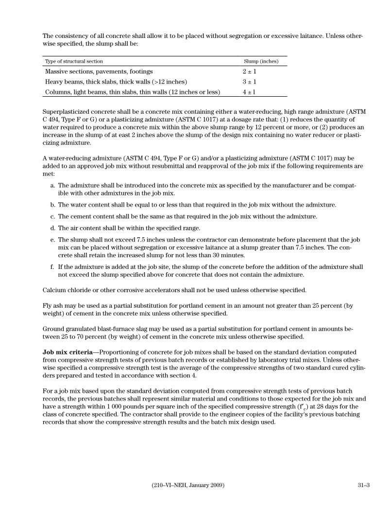
31–3(210–VI–NEH, January 2009)
The consistency of all concrete shall allow it to be placed without segregation or excessive laitance. Unless other-wise specified, the slump shall be:
Type of structural section Slump (inches)
Massive sections, pavements, footings 2 ± 1
Heavy beams, thick slabs, thick walls (>12 inches) 3 ± 1
Columns, light beams, thin slabs, thin walls (12 inches or less) 4 ± l
Superplasticized concrete shall be a concrete mix containing either a water-reducing, high range admixture (ASTM C 494, Type F or G) or a plasticizing admixture (ASTM C 1017) at a dosage rate that: (1) reduces the quantity of water required to produce a concrete mix within the above slump range by 12 percent or more, or (2) produces an increase in the slump of at east 2 inches above the slump of the design mix containing no water reducer or plasti-cizing admixture.
A water-reducing admixture (ASTM C 494, Type F or G) and/or a plasticizing admixture (ASTM C 1017) may be added to an approved job mix without resubmittal and reapproval of the job mix if the following requirements are met:
a. The admixture shall be introduced into the concrete mix as specified by the manufacturer and be compat-ible with other admixtures in the job mix.
b. The water content shall be equal to or less than that required in the job mix without the admixture.
c. The cement content shall be the same as that required in the job mix without the admixture.
d. The air content shall be within the specified range.
e. The slump shall not exceed 7.5 inches unless the contractor can demonstrate before placement that the job mix can be placed without segregation or excessive laitance at a slump greater than 7.5 inches. The con-crete shall retain the increased slump for not less than 30 minutes.
f. If the admixture is added at the job site, the slump of the concrete before the addition of the admixture shall not exceed the slump specified above for concrete that does not contain the admixture.
Calcium chloride or other corrosive accelerators shall not be used unless otherwise specified.
Fly ash may be used as a partial substitution for portland cement in an amount not greater than 25 percent (by weight) of cement in the concrete mix unless otherwise specified.
Ground granulated blast-furnace slag may be used as a partial substitution for portland cement in amounts be-tween 25 to 70 percent (by weight) of cement in the concrete mix unless otherwise specified.
Job mix criteria—Proportioning of concrete for job mixes shall be based on the standard deviation computed from compressive strength tests of previous batch records or established by laboratory trial mixes. Unless other-wise specified a compressive strength test is the average of the compressive strengths of two standard cured cylin-ders prepared and tested in accordance with section 4.
For a job mix based upon the standard deviation computed from compressive strength tests of previous batch records, the previous batches shall represent similar material and conditions to those expected for the job mix and have a strength within 1 000 pounds per square inch of the specified compressive strength (f′c) at 28 days for the class of concrete specified. The contractor shall provide to the engineer copies of the facility's previous batching records that show the compressive strength results and the batch mix design used.

31–4 (210–VI–NEH, January 2009)
For a job mix based upon a laboratory trial mix, the trial mix shall contain the actual material to be used in the final job mix, have a slump within 0.75 inches of the maximum allowable slump, and have an air content within 0.5 percent of the maximum allowable air content. The contractor shall provide the engineer with copies of the actual compressive strength test records for the trial mix from the testing facility performing the test.
The trial job mix or previous batch records shall include the water reducing admixture when a water reducing admixture is used in a concrete mix specifically to improve the physical properties of the hardened concrete or change portions of the mix components.
In meeting strength requirements, the selected job mix proportions must produce an average strength, fcr, exceed-ing the specified compressive strength, f′c, by the amount specified below.
n s30 fcr
>30 1.00 s The larger of these
25 1.03 s two equations:
20 1.08 s f′c + 1.34 s30
15 1.16 s f′c + 2.33 s30–500
<15 f′c + 1,000 for f′c < 3,000
f′c + 1,200 for f′c 5,000
f′c + 1,400 for f′c > 5,000
where:n = number of consecutive compressive strength testss30 = standard deviation adjusted to 30 tests, lb/in2
fcr = required average compressive strength, lb/in2
f′c = specified compressive strength of concrete, lb/in2
s = standard deviation (lb/in2) computed as {[sum(Xi-Xa)2]/[n-1]}1/2
where: Xi = individual strength test result, lb/in2
Xa = average of n strength test results, lb/in2
Method 2Responsibilities—The engineer is responsible for the design and proportioning of the job mix. The initial job mix will be as specified in section 25. The engineer may adjust the initial job mix proportions to establish the des-ignated job mix. The engineer will provide the contractor with a copy of each job mix as soon as the material and proportions have been determined. After the job mix has been designated, neither the source, character, or grada-tion of the aggregates nor the type or brand of cement or admixtures shall be changed without prior approval of the engineer. During the course of the work, the engineer may adjust the job mix proportions and batch weights when-ever necessary to meet special job conditions.

31–5(210–VI–NEH, January 2009)
The contractor, for each class of concrete, shall be responsible for: a. Taking the following actions and furnishing the engineer with the following information at least 35 calendar
days before any placement of concrete, unless otherwise designated: (1) Select the source of aggregates and sample and test the gradations of aggregates available. (2) Select the brand and type of cement. (3) Select the brand of admixtures and obtain manufacturer's test data and recommendation of use. (4) Identify the concrete production facility, the type of mixer, and the mixing methods that will be used. (5) Provide from the concrete production facility consecutive compressive strength test records and batch-
ing records for concrete mixes that have material, proportions, and compressive strengths within 1 000 pounds per square inch of the proposed design mix.
b. Batching at least 3 cubic yards of the initial job mix, in the presence of the engineer, for testing and evalua-tion not less than 30 calendar days before any placement of concrete.
4. Inspecting and testingDuring the course of the work, the engineer performs quality assurance testing as required to assure the concrete meets the contract requirements. The engineer shall have free entry to the plant and equipment furnishing concrete under the contract. Proper facilities shall be provided for the engineer to inspect material, equipment, and process-es, and to obtain samples of the concrete. All tests and inspections are conducted so as not to interfere unnecessar-ily with the manufacture, delivery, and placement of the concrete.
Any portion of a batch may be tested by the engineer for any of the purposes shown below. Samples taken for test-ing shall be representative of that part of the batch.
a. Determining uniformity of the batch.
b. Checking compliance with requirements for slump and air content when the batch is discharged over an extended period.
c. Checking compliance of the concrete with the specifications when the whole amount being placed in a small structure, or a distinct part of a larger structure, is less than full batch.
If concrete is conveyed to the placement location by pumping or conveyor belts, the samples shall be collected at the discharge end.
When a plasticizing admixture is added to the concrete mix at the job site, slump tests are made both before the ad-dition of the admixture to the concrete mix and after the admixture has been incorporated into the concrete mix.
The tests on concrete are performed by the following methods unless otherwise specified:
Type of test Test method(ASTM designation)
Sampling C 172
Slump test C 143
Air content C 231 or C 173
Compression test specimens C 31 or C 42
Compressive strength testing C 39
Unit weight C 138
Temperature C 1064

31–6 (210–VI–NEH, January 2009)
A strength test for concrete is the average of two standard cured concrete cylinders prepared in accordance with ASTM C 31 from the same sample of concrete and tested in accordance with ASTM C 39 at 28 days, unless other-wise specified. If one cylinder shows manifest evidence of improper sampling, molding, curing, or testing, it shall be discarded and the strength of the remaining cylinder shall then be considered the compressive strength of the concrete. Should both cylinders show such defects, the entire test shall be discarded.
If both cylinders are discarded or inplace concrete that was not sampled is in question, the inplace concrete may be sampled by coring in accordance with ASTM C 42. For core tests, these requirements shall be followed:
a. At least three representative cores shall be taken from each area of concrete in question. If one or more of the cores shows signs of being damaged before testing, it shall be replaced by a new one.
b. Test cores shall be prepared for testing in accordance with moisture conditioning in ASTM C 42 unless the engineer determines that the concrete in the structure will be dry under service conditions. If the concrete is determined to be dry under service conditions, the cores shall be air dried (temperature 60 °F to 80 °F and relative humidity less than 60%) for 7 days before testing and shall be tested dry.
5. Handling and measurement of materialAggregates shall be stored or stockpiled in such a manner that separation of coarse and fine particles of each size is avoided and that various sizes do not become intermixed before proportioning. Methods of handling and transport-ing aggregates shall avoid contamination, excessive breakage, segregation, degradation, or intermingling of various sizes.
Unless otherwise specified, scales shall be beam type or springless dial type. They shall be accurate when static load tested to plus 0.4 percent of the total capacity of the scales. All exposed fulcrums, clevises, and similar work-ing parts of scales shall be kept clean.
Measuring tanks for mixing water shall be of adequate capacity to furnish the maximum amount of mixing water required per batch. Tanks shall be equipped with outside taps and valves to verify their calibration unless other means are provided for readily and accurately determining the amount of water in the tank.
The quantities of each component of the concrete mix shall be measured by the following methods and to the ac-curacy indicated below:
Cement, fly ash, slag—Cement, except as otherwise specifically permitted, shall be measured by weight or in bags on which the weight is plainly marked. When cement, fly ash, and slag are supplied in bulk and are measured by weight, they shall be weighed on a scale separate from that used for other material and in a hopper entirely free and independent of the hopper used for weighing the aggregate. When fly ash or slag is used in the job mix, the cement and the fly ash or slag may be weighed separately or cumulatively by weighing the cement first and then adding the fly ash or slag to arrive at the composite weight. The weight of the cement and the combined weight of the cement and fly ash or slag shall be within plus or minus 1 percent of the required weight of the cementitious material. When cement is measured in bags, no fraction of a bag shall be used unless weighed.
Aggregates—Aggregates shall be measured by weight unless otherwise specifically permitted. Mix proportions shall be based on saturated, surface-dry weights. The batch weight of each aggregate shall be the required saturat-ed, surface-dry weight corrected by the weight of surface moisture it contains. The weight of each of the specified aggregates shall be within plus or minus 2 percent of the required weight.

31–7(210–VI–NEH, January 2009)
Mixing water—Mixing water shall consist of water added to the batch, ice added to the batch, water occurring as surface moisture on the aggregates, and water introduced in the form of admixtures. The added water shall be measured by weight or volume to an accuracy of l percent of the required total mixing water. Added ice shall be measured by weight. Wash water shall not be used as part of the mixing water for succeeding batches.
Admixtures—Dry admixtures shall be measured by weight. Paste or liquid admixtures shall be measured by weight or volume. The admixtures shall be within plus or minus 3 percent of the required weight or volume for each specific admixture.
6. Mixers and mixingMixers are either stationary parts of a central mixing plant or portable equipment, such as revolving drum truck mixers and volumetric batching/continuous mixing truck mixers. Mixers shall be capable of thoroughly mixing the concrete ingredients into a uniform mass within the specified mixing time and of discharging the mix without seg-regation. Each mixer or agitator shall bear a manufacturer's rating plate indicating the gross volume of the drum, the capacity of the drum or container in terms of the volume of mixed concrete, and the minimum and maximum mixing speeds of rotation of the drum, blades, or paddles. When the truck mixer is used for truck mixed concrete as described in section 6a(2) or for shrink mixed concrete as described in section 6a(3), the capacity of the drum or container in terms of the volume of mixed concrete shall not exceed 63 percent of the gross volume of the drum. When the truck mixer is used to transport central-mixed concrete as described in section 6a(1), the capacity of the drum or container in terms of the volume of mixed concrete shall not exceed 80 percent of the gross volume of the drum. The mixer shall be operated in accordance with these recommendations.
Concrete shall be uniform and thoroughly mixed when delivered to the forms in a freshly mixed and unhardened state. Variations in slump of more than 1 inch within a batch is considered evidence of inadequate mixing and shall be corrected by changing batching procedures, increasing mixing time, changing mixers, or other means. Mixing time shall be within the limits specified below unless the contractor demonstrates by mixer performance tests that adequate uniformity is obtained by different times of mixing.
No mixing water in excess of the amount called for by the job mix shall be added to the concrete during mixing or hauling or after arrival at the delivery point. Water to compensate for up to a 1-inch loss in slump may be added, not to exceed the design maximum water cement ratio. Withholding some of the mixing water until the concrete arrives on the job, then adding the remaining water and turning the mixer 30 revolutions at mixing speed is allowed to overcome transporting conditions. When loss of slump or workability cannot be offset by these measures, com-plete mixing shall be performed by onsite batching and mixing or by using a combination of centrally batching and transporting material to the site and adding remainder of material onsite.
Concrete may be furnished by ready-mix methods, by volumetric batching and continuous mixing at the site, or by batch mixing at the site.
a. Ready-mixed concreteReady-mixed concrete shall be mixed, transported, and placed in a freshly mixed and unhardened state. The con-tractor shall furnish the engineer a batch ticket showing amount of concrete in cubic yards, the time of loading, the time the load was discharged, the revolution counter reading at the time of loading and discharge, and the type and actual quantity of each material including all admixtures used in each batch of concrete.

31–8 (210–VI–NEH, January 2009)
Truck mixers and truck agitators shall be equipped with revolution counters by which the number of revolutions of the drum or blades may be readily verified. Ready-mixed concrete shall be mixed and delivered by one of the following methods:
(1) Central-mixed concrete—Central-mixed concrete is mixed completely in a stationary mixer and trans-ported to the point of delivery either in a truck agitator, a truck mixer operating at agitating speed, or nonagitating equipment.
When a truck agitator or a truck mixer is used as an agitator and transports concrete that has been com-pletely mixed in a stationary mixer, mixing during transportation shall be at the speed designated by the manufacturer of the equipment as agitating speed. When concrete is transported in a truck mixer or truck agitator, the volume of the mixed concrete shall not exceed 80 percent of the gross volume of the drum. The total number of revolutions of the truck mixer or truck agitator shall not exceed 200 before discharge of the concrete, unless otherwise specified.
The use of nonagitating equipment to transport concrete to the site of the work is permitted only if the consistency and uniformity of the concrete as discharged at the point of delivery meet the requirements of this specification. Bodies of nonagitating hauling equipment shall be constructed so that leakage of the concrete mix, or any part thereof, does not occur. Concrete hauled in opentop vehicles shall be protected from rain and from more than 20 minutes exposure to the sun and wind when the air temperature is above 75 degrees Fahrenheit.
(2) Truck-mixed concrete—Truck-mixed concrete is completely mixed in a truck mixer. The total volume of all ingredients to be mixed in a revolving drum truck mixer shall not exceed 63 percent of the gross volume of the drum. The concrete ingredients shall be mixed between 70 and 100 revolutions of the drum or blades at the speed designated by the manufacturer as mixing speed. Mixing in excess of 100 revolu-tions shall be at the speed designated by the manufacturer of the equipment as agitating speed. The total number of revolutions shall not exceed 300 before discharge of the concrete unless otherwise specified.
(3) Shrink-mixed concrete—Shrink-mixed concrete is partly mixed at a central plant and the mixing is com-pleted in a truck mixer. The mixing time in the central plant mixer is the minimum required to intermin-gle the ingredients. The volume of the mixed concrete in a truck mixer shall not exceed 63 percent of the gross volume of the truck drum. The mixing shall be completed in a truck mixer. The number of revolu-tions of the truck mixer drum or blades shall be between 50 and 100 revolutions at the speed designated by the manufacturer as mixing speed. Mixing in excess of 100 revolutions shall be at the speed desig-nated by the manufacturer of the equipment as agitating speed. The total number of revolutions shall not exceed 300 before discharge of the concrete unless otherwise specified.
b. Volumetric batching and continuous mixing at the site Volumetric batching and continuous mixing at the site is commonly referred to as mobile concrete mixers. Unless otherwise specified volumetric batching and continuous mixing at the construction site is permitted. The batching and mixing equipment shall conform to the requirements of ASTM C 685 and shall be demonstrated before place-ment of concrete by tests with the job mix to produce concrete meeting the specified proportioning and uniformity requirements. Concrete made by this method shall be produced, inspected, and documented in conformance with sections 6, 7, 8, 13, and 14 of ASTM C 685.

31–9(210–VI–NEH, January 2009)
c. Batch mixing at the siteThis method of batching and mixing concrete is either by batching and mixing all material onsite using paving mix-ers or stationary construction mixers or by using a combination of centrally batching part of the mix, transporting it to the site, and adding the rest of the material and mixing onsite.
Paving mixers or stationary construction mixers and associated transport vehicles shall be in accordance with rec-ommended practices described in method 1 for central mixed concrete. The time for mixing a batch of concrete in the mixer drum shall be according to manufacturer's recommendations, but not less than 1 minute plus 0.25 minute for each cubic yard of concrete being mixed (8 yd3 batch = 3 minutes).
When a combination of centrally batching and transporting material to the site and adding rest of material onsite is used, the contractor shall prepare a written plan detailing how the batching and mixing of the concrete mate-rial will be accomplished and controlled. This written batching and mixing plan shall be submitted to the engineer for review and approval not less than 10 working days before the placement of concrete. The volume of the mixed concrete in a truck mixer shall not exceed 63 percent of the gross volume of the drum.
The contractor shall furnish the engineer a batching ticket for each batch of fresh concrete. The ticket shows the type, brand, and amount of cement; the type, name, and amount of each admixture; total water added to the batch, which includes free water on the aggregate; maximum size of aggregate; the type and dry weight of fine aggregate; the type and dry weight of coarse aggregate; the time of loading (the time that water was introduced to the ce-ment); and the time the load was discharged.
7. FormsForms shall be of good quality wood, plywood, steel, or other approved material and shall be mortar tight. The forms and associated falsework shall be substantial and unyielding and shall be constructed so that the finished concrete conforms to the specified dimensions and contours. Form surfaces shall be smooth and free from holes, dents, sags, or other irregularities and shall be maintained in this condition throughout the work. Forms shall be coated with a nonstaining form release agent before being set into place. Acceptable tolerances for formed struc-ture members are specified in section 23.
When a superplasticized concrete mix is used, forms shall be coated according to the manufacturer's recommenda-tions with a form release agent that is specifically formulated for plasticized concrete. Forms shall be designed to withstand the increased pressures of the superplasticized concrete and the increased impact forces resulting from larger drop heights used in placing the superplasticized concrete.
Metal ties or anchorages that will be embedded in the concrete shall be equipped with cones, she-bolts, or other devices that permit their removal to a depth of at least 1 inch without injury to the concrete. Ties designed to break off below the surface of the concrete shall not be used without cones. If approved fiberglass or plastic form ties are used, the tie ends shall be cut flush with the finished concrete and ground smooth.
All edges that will be exposed shall be chamfered unless finished with molding tools as specified in section 18.
8. Preparation of forms and subgradeBefore placement of concrete, the forms, embedments, and subgrade shall be free of chips, sawdust, debris, water, ice, snow, extraneous oil, mortar, or other harmful substances or coatings. Any form release agent on the reinforc-ing steel or other surfaces required to be bonded to the concrete shall be removed.

31–10 (210–VI–NEH, January 2009)
Rock surfaces shall be cleaned by high pressure air-water cutting, sandblasting, or wire brush scrubbing, as nec-essary, and shall be wetted immediately before placement of concrete. The earth surface shall be firm and damp. Placement of concrete on mud, dried earth, noncompacted fill, or frozen subgrade is not permitted. All ice, snow, and frost shall be removed, and the temperature of all surfaces, including the reinforcing steel and other steel inclu-sions, to be in contact with the new concrete shall be no colder than 40 degrees Fahrenheit.
Items to be embedded in the concrete shall be positioned accurately and anchored firmly.
Weepholes in walls or slabs shall be formed with nonferrous material.
9. ConveyingConcrete shall be delivered to the site and discharged completely into the forms within 1.5 hours or before the drum of truck has revolved a total of 300 revolutions, whichever comes first, after the introduction of the mixing water to the cement and aggregates or the introduction of the cement to the aggregates. In hot weather or under conditions contributing to quick stiffening of the concrete, or when the temperature of the concrete is 85 degrees Fahrenheit or above, the time between the introduction of the cement to the aggregates and discharge shall not exceed 45 minutes.
Superplasticized concrete can be conveyed and placed when the temperature of the concrete is below 95 degrees Fahrenheit and the slump of the concrete remains within the allowable slump range.
The engineer can allow an appropriate extension of time when the setting time of the concrete is increased a corre-sponding amount by the addition of an approved admixture. In any case concrete shall be conveyed from the mixer to the forms as rapidly as practicable by methods that prevent segregation of the aggregates or loss of mortar.
10. PlacingConcrete shall not be placed until the subgrade, forms, steel reinforcement, and other embedments are inspected and approved by the engineer. For walls and columns, subsequent higher placements of concrete shall not be placed until the concrete below the new placement has gained sufficient strength to support the concrete dead load and any superimposed loads without distress. Placement sequences and timing shall consider form removal timing covered in section 16.
If a placement plan is required in section 25, concrete shall not be placed until the placement plan has been re-viewed and approved by the engineer. The contractor shall have all equipment and material required for curing available at the site ready for use before placement of concrete begins.
Concrete shall be placed only in the presence of the engineer. The contractor shall give reasonable notice to the engineer before each placement. Such notice shall be far enough in advance to give the engineer adequate time to assure that the subgrade, forms, steel reinforcement, and other preparations comply with specifications. Other preparations include, but are not limited to, the concrete batching plant, mixing and delivery equipment and sys-tem, placing and finishing equipment and system, schedule of work, workforce, and heating or cooling facilities, as applicable. All deficiencies are to be corrected before concrete is delivered for placing.
Concrete shall be placed and consolidated to prevent segregation of the mix components. The concrete shall be deposited as closely as possible to its final position in the forms. It shall be worked into the corners and angles of the forms and around all reinforcement and embedded items to prevent segregation of aggregates or excessive laitance. The depositing of concrete shall be regulated so that the concrete can be consolidated with a minimum of lateral movement. Concrete placed against a sloping surface shall start at the lowest elevation and work upwards to the highest elevation.

31–11(210–VI–NEH, January 2009)
Concrete other than architectural concrete shall not be dropped more than 5 feet vertically unless suitable equip-ment is used to prevent segregation. Architectural concrete shall not be dropped more than 3 feet vertically unless suitable equipment is used to prevent segregation. When a superplasticized concrete mix is used, concrete other than architectural concrete shall not be dropped more than 12 feet vertically and architectural concrete shall not be dropped more than 10 feet vertically unless suitable equipment is used to prevent segregation.
11. LayersSlab concrete shall be placed to design thickness in one continuous layer unless otherwise specified. Formed con-crete shall be placed in horizontal layers not more than 20 inches deep. Where a superplasticized concrete mix is used, formed concrete may be placed in horizontal layers not more than 5 feet deep.
Successive layers of fresh concrete between construction joints shall be placed at a rate fast enough that the pre-ceding layer is still plastic and can be easily mixed with the fresh concrete such that seams (cold joints) or plane of weakness do not occur. If the surface of a previously placed layer of concrete has taken a set to the degree that it will not flow and mix with the succeeding layer when vibrated, the contractor shall discontinue placing concrete and shall make a construction joint according to the procedure specified in section 13. If placing is discontinued when a layer is incomplete, the ends of the incomplete layer shall be formed by a vertical bulkhead.
12. ConsolidatingAll concrete shall be consolidated with internal type mechanical vibrators capable of transmitting vibration to the concrete at frequencies not less than 8,000 impulses per minute, unless otherwise specified or approved before placement. Vibration shall be supplemented by spading, rodding, and hand tamping as necessary to ensure smooth and dense concrete along the form surface, in corners, and around embedded items. The contractor shall provide a sufficient number of vibrators to properly consolidate the concrete immediately after it is placed. A sufficient number of standby vibrators shall be kept onsite during the placement of concrete.
Vibration shall compact the concrete and bring it into intimate contact with the forms, reinforcing steel, and other embedded items while removing voids and pockets of entrapped air. The location, insertion, duration, and removal of the vibrators shall be such that maximum consolidation of the concrete is achieved without causing segrega-tion of the mortar and coarse aggregate or causing water or cement paste to flush to the surface. Vibration shall be applied to the freshly deposited concrete by rapidly inserting the vibrator and slowly, in an up and down motion, removing the vibrator at points uniformly spaced at not more than 1.5 times the radius of the area visibly effected by vibration. Generally, this is at 5 to 10 seconds per foot on 14-inch spacings or less. The area visibly effected by the vibrator shall overlap the adjacent, just vibrated area. The vibrator shall extend vertically into the previously placed layer of fresh concrete by at least 6 inches at all points. This ensures effective bond between layers. In thin slabs the vibrator(s) should be sloped toward the horizontal to allow operations in a fully embedded position.
Vibration shall not be applied directly to the reinforcement steel, the forms, or other embedded items unless other-wise specified. Vibration shall not be applied to concrete that has hardened to the degree that it does not become plastic when vibrated. If surface vibrators are used, they may contact forms when consolidating thin slabs.
The use of vibrators to transport concrete in the forms or conveying equipment is not permitted.
Surface vibrators may be used to consolidate slabs 8 inches and less in thickness. Slabs more than 8 inches thick shall be consolidated with internal vibration and may be augmented through use of surface vibrator, such as vi-

31–12 (210–VI–NEH, January 2009)
brating screeds, plate or grid vibratory tampers, or vibratory roller screeds. If concrete is to be consolidated using surface vibration methods, the contractor shall detail how this work is to be performed in writing to the engineer for review and approval. This report must be submitted no less than 30 calendar days before placing concrete by this method. It includes equipment selection and specifications.
13. Construction jointsConstruction joints shall be made at the locations shown on the drawings unless otherwise specified or approved by the engineer. If construction joints are needed that are not shown on the drawings, they shall be placed in loca-tions approved by the engineer.
Where a feather edge would be produced at a construction joint, as in the top surface of a sloping wall, an insert form shall be used so that the resulting edge thickness on either side of the joint is not less than twice the maxi-mum aggregate diameter used in the concrete mix.
Nonvertical construction joints in structural elements, such as walls and columns, shall be consolidated and screeded to grade unless otherwise specified. Construction joints shall be covered and wet cured for 7 days or until concrete placement resumes unless otherwise specified.
Steel tying and form construction next to concrete in place shall not be started until the concrete has cured at least 12 hours. Before new concrete is deposited on or against concrete that has hardened, the forms shall be retight-ened. New concrete shall not be placed until the hardened concrete has cured at least 12 hours.
Method l—The surface of construction joints shall be cleaned of all unsatisfactory concrete, laitance, coatings, stains, or debris by sandblasting or high-pressure air-water cutting, or both. Sandblasting can be used after the con-crete has gained sufficient strength to resist excessive cutting, and high-pressure air-water cutting can be used as soon as the concrete has hardened sufficiently to prevent the jet from displacing the coarse aggregates. The surface of the concrete in place shall be cut to expose clean, sound aggregate, but not so deep as to undercut the edges of larger particles of the aggregate. After cutting, the surface shall be thoroughly washed to remove all loose material. If the surface is congested by reinforcing steel, is relatively inaccessible, has cured beyond the ability to cut with air-water blasting, or disturbing the concrete before it is hardened is considered undesirable, cleaning of the joint by air or water jets is not permitted. The sandblasting method is required after the concrete has hardened.
Immediately before new concrete is placed, all construction joints shall be wetted and standing water removed.
Method 2—The surface of construction joints shall be cleaned of all unsatisfactory concrete, laitance, coatings, stains, or debris by washing and scrubbing with a wire brush or wire broom, or by other means approved by the engineer. Immediately before new concrete is placed, all construction joints shall be wetted and standing water removed.
14. Expansion and contraction jointsExpansion and contraction joints shall be made only at locations shown on the drawings. Exposed concrete edges at expansion and contraction joints shall be carefully tooled or chamfered, and the joints shall be free of mortar and concrete. Joint filler shall be fully exposed for its entire length with clean and true edges.
Where open joints or weakened plane "dummy" joints are specified, joints formed in fresh concrete shall be con-structed by the insertion and subsequent removal of a wood strip, metal plate, or other suitable template. This will be done so that the corners of the concrete do not chip or break. The edges of the fresh concrete at the joints shall

31–13(210–VI–NEH, January 2009)
be finished with an edging tool before the joint strips are removed. Open joints or weakened plane dummy joints may also be sawcut joints conforming to the depth and extent specified.
Preformed expansion joint filler shall be held firmly in the correct position as the concrete is placed.
15. WaterstopsWaterstops shall be held firmly in the correct position as the concrete is placed. Joints in metal waterstops shall be brazed or welded. Joints in rubber or plastic waterstops shall be cemented, welded, or vulcanized as recommended by the manufacturer. Joints shall be watertight and of a strength equivalent to that specified in Material Specifica-tion 537. Intersecting waterstop joints shall be prefabricated and supplied by the same manufacturer providing the waterstop.
16. Removal of forms, supports, and protective coveringsForms, supports, and protective coverings shall be removed as soon as practical after the concrete has gained sufficient strength to support its own weight and superimposed loads. Removal shall be done so that the concrete surface is not damaged and sudden or excessive stresses are not induced. The minimum period from completion of the concrete placement to the removal of the forms shall be based on either strength tests or cumulative times.
Strength tests—The strength of the inplace concrete is determined by testing concrete cylinders specifically cast for this purpose and cured adjacent to the member in accordance with the ASTM C 31 method for determining removal time. Unless otherwise specified, forms supporting the weight of the concrete member may be removed after the concrete strength is 70 percent of that specified for the class of concrete. Forms not supporting the weight of the concrete member or other superimposed loads may be removed after the concrete strength has reached the strength specified in section 25.
Cumulative time—The total accumulated time, not necessarily continuous, that the air adjacent to the concrete is above 50 degrees Fahrenheit and the specified concrete curing has occurred concurrently will be determined. Forms may be removed after the total accumulated time shown:
Accumulated form removal times
Forms Time 1/
Sides of slabs or beams 12 hours
Undersides of slabs or beams Clear span 2/
< 10 ft 4 days
10 - 20 ft 7 days
> 20 ft 14 days
Sides of walls or columns Height above form 3/ 4/
< 10 ft 12 hours
< 20 ft 24 hours
> 20 ft 72 hours
1/ Table values apply to normal concrete. Values for concrete that contains cements or admixtures that significantly retard or accelerate strength gain will be determined by the engineer and based on actual design mix data.
2/ Values apply to members designed to support significant superimposed loads. Values for members designed for only self weight when placed in service shall be 50 percent greater.
3/ Values apply to members not subject to significant horizontal loads. Additional time or rebracing is needed for members subject to significant wind or other horizontal loads.
4/ Subsequent higher lifts may be placed after 12 hours.

31–14 (210–VI–NEH, January 2009)
17. Finishing formed surfacesAll formed concrete surfaces shall be true and even, and shall be free from overtolerance depressions, holes, pro-jections, bulges, or other defects in the specified surface finish or alignment, unless otherwise specified in section 25. Depressions are measured as the distance from the bottom of a 5-foot-long template or straight edge.
A surface to be backfilled or otherwise concealed when construction is completed shall have the following surface treatment unless otherwise specified:
• Repairdefectiveconcrete.
• Fillallformtieholes.
• Correctsurfacedepressionsdeeperthan1inch.
• Removeorsmoothfinsandabruptprojectionsthatexceed0.75inch.
A surface to be permanently exposed, where other finishes are not specified, shall have the following treatment:
• Repairdefectiveconcrete.
• Fillallformtieholes.
• Removeorsmoothallabruptirregularitiesgreaterthan0.25inchindepthorprojection.
• Treatalldepressionsandirregularitiessothattheydonotexceed0.5inchindepth.
Form bolt and tie holes and other holes of similar size and depth shall be repaired and filled as specified in section 20.
18. Finishing unformed surfacesAll exposed surfaces of the concrete shall be accurately screeded to grade and then float finished unless otherwise specified. The float finish shall result in a surface that has no irregularities of more than 0.25 inch when checked with a template or straight edge that is 10 feet long.
All exposed surfaces of concrete shall be accurately struck off to grade after placement and consolidation are completed. Following strikeoff, the surface shall be immediately smoothed by darbying or bull floating before any free water has bled to the surface. The concrete shall then be allowed to rest until the bleed water and water sheen have left the surface and the concrete has stiffened to where it will sustain foot pressure with only about 0.25-inch indentation. At this time all joints and edges that are exposed to view and are not chamfered shall be finished with edging tools. After edging and hand jointing is complete, all exposed surfaces shall be floated with wood or mag-nesium floats. The floating should work the concrete no more than necessary to remove screed, edger, and jointer marks and to produce a compact surface uniform in texture.
Water shall not be sprinkled or added to the surface of the concrete during the darbying, bull floating, floating, or other finishing operations to facilitate finishing.
19. CuringFreshly placed concrete shall be cured a minimum of 7 days in accordance with the recommended practices set forth in this section. A curing process shall be started as soon as the concrete has hardened sufficiently to prevent surface damage. Curing concrete, including exposed surfaces of formed concrete and concrete in forms, shall be

31–15(210–VI–NEH, January 2009)
maintained at a satisfactory moisture content for at least 7 days following placement. If forms are removed before the end of the 7-day curing period, the interrupted curing process shall be reestablished and maintained until a full 7-day curing period is achieved. A satisfactory moisture condition is:
• Continuousorfrequentapplicationofwateroruseofasaturatedcovermaterial,suchascanvas,cloth,burlap, earth, or sand.
• Preventionofexcessivewaterlossfromtheconcretebyuseofanimpermeablecoating(curingcompound)or covering (plastic, paper).
The application of water or covering shall not erode, mar, or otherwise damage the concrete. Plastic film or paper shall meet the requirements of ASTM C 171. Black covering shall not be used when concreting in hot weather.
Except as otherwise specified in section 25, curing compound may be used for exposed surfaces or formed sur-faces after patching and repair are completed. Curing compounds shall not be used on a surface that is to receive additional concrete, paint, tile, or other coatings unless the contractor demonstrates that the membrane can be satisfactorily removed or can serve as a base for the later application.
Curing compound shall be thoroughly mixed before applying and be agitated during application. Except as other-wise specified in section 25, the compound shall be applied at a pressure of 75 to 100 pounds per square inch. A continuously agitating pressure sprayer is used for application at a uniform rate of not less than 1 gallon per 175 square feet of surface. Manual hand pump sprayers shall not be used unless otherwise specified. For individual concrete placements or repairs having a surface area of 400 square feet or less, curing compound may be applied with a soft-bristled brush, paint roller, or hand sprayer. The compound shall form a uniform, continuous, adherent film that shall not check, crack, or peel and shall be free from pinholes or other imperfections.
All surfaces covered with curing compound shall be continuously protected from damage to the protective film during the required curing period.
A surface subjected to heavy rainfall or running water within 3 hours after the compound has been applied or that is damaged by subsequent construction operations during the curing period shall be resprayed in the same manner as for the original application.
Water for curing shall be clean and free from any substances that cause discoloration of the concrete.
20. Concrete patching, repair or replacementPatching—All form bolts, metal ties, and similar forming restraints shall be removed to a depth of 1 inch below the surface of the concrete and their cavities repaired unless otherwise specifically permitted or specified. Small cavities, large air holes, minor honeycombed areas, and other superficial imperfections that require patching to meet the specified finish requirements shall be thoroughly cleaned and filled. Holes left by bolts or straps that pass through the concrete section shall be filled solid with a dense, well-bonded, nonshrink patching material. Dry-pack mortar and replacement concrete shall follow the appropriate procedure detailed in the Repair and Maintenance chapter of the Concrete Manual, Bureau of Reclamation, U.S. Department of the Interior. Proprietary patching ma-terial shall be appropriate for the type of repair, used within the manufacturer's recommended limits, and applied according to the manufacturer's recommendations.
Repair or replacement—The contractor shall repair or replace concrete that does not meet the requirements of this specification. Before starting any repair or replacement work, the contractor shall prepare a written plan for the repair or replacement. The primary reference for material and repair methods for the plan shall be the appropriate sections of the Repair and Maintenance chapter of the Concrete Manual, Bureau of Reclamation, U.S. Department of the Interior. The repair plan shall be submitted to the engineer for review at least 10 days before any repair or replacement work. Approval of the plan will be authorized in writing by the contracting officer.

31–16 (210–VI–NEH, January 2009)
When proprietary patching material is proposed in the plan, the manufacturer's data sheets and written recommen-dations shall be included in the plan.
Repair material or replacement concrete shall have properties, color, and texture similar to and compatible with the concrete being repaired or replaced. Repair or replacement concrete work shall be performed only when the engineer is present.
Curing of repaired or replaced concrete shall be started immediately after finish work is completed and as specified in section 19 or as specified by the manufacturer of proprietary compounds.
21. Concreting in cold weatherMethods for concreting in cold weather shall be performed when, for more than 3 consecutive days, the following conditions exist:
• Theaveragedailyairtemperatureatthejobsiteislessthan40degreesFahrenheit.(Theaveragedailyairtemperature is the average of the highest and lowest temperatures occurring during the period from mid-night to midnight.)
• Theairtemperatureatthejobsiteisnotmorethan50degreesFahrenheitformorethanhalfofany24-hourperiod.
Concrete shall be protected against freezing during the first 24 hours after placement whether or not the average weather conditions specified above for cold weather concreting exist. The following provisions also shall apply un-less otherwise specified:
a. When the cement is added to the mix, the temperature of the mixing water shall not exceed 140 degrees Fahrenheit nor shall the temperature of the aggregate exceed 150 F.
b. The temperature of the concrete at the time of placing shall be within the placement temperature range shown below, unless otherwise specified.
Least dimension of section, inches Placement temperature, °F
Less than 12 55 – 75
12 to 36 50 – 70
36 to 72 45 – 65
Greater than 72 40 – 60
c. The minimum temperature of the concrete for the first 72 hours after placement shall not be less than the minimum temperature shown above. Concrete structures shall be immediately protected after concrete placement by covering, housing, insulating, or heating concrete structures sufficiently to maintain the mini-mum temperature adjacent to the concrete surface. If the minimum temperature requirements are not met and the concrete did not freeze, the protection time will be extended a period equal to twice the number of hours the temperature was below the minimum temperature.
d. Exhaust flue gases from combustion heaters shall be vented to the outside of the enclosure. The heat from heaters and ducts shall be directed in such a manner as to not overheat or dry the concrete in localized areas or to dry the exposed concrete surface.
e. At the end of the protection period, the concrete shall be allowed to cool gradually. The maximum decrease at the concrete surface in a 24-hour period shall not exceed 40 degrees Fahrenheit.

31–17(210–VI–NEH, January 2009)
22. Concreting in hot weatherMethods for concreting in hot weather shall be in accordance with the requirements set forth below.
For the purpose of this specification, hot weather is defined as any combination of the following conditions that im-pair the quality of freshly mixed or hardened concrete by accelerating the rate of moisture loss and rate of cement hydration, or otherwise resulting in detrimental results:
• Highambienttemperature
• Highconcretetemperature
• Lowrelativehumidity
• Windvelocity
• Solarradiation
Whenever the above conditions exist or when climatic conditions are such that the temperature of the concrete may reasonably be expected to exceed 90 degrees Fahrenheit at the time of delivery to the worksite or during the placement operations, the following provisions shall apply:
a. The contractor shall maintain the temperature of the concrete below 90 degrees Fahrenheit during mixing, conveying, and placing.
b. Exposed concrete surfaces that tend to dry or set too rapidly shall be continuously moistened using fog sprays or other means to maintain adequate moisture during the time between placement and finishing. Water shall not be sprinkled or added directly to the surface of the concrete before finishing.
c. Finishing of slabs and other exposed surfaces shall be started as soon as the condition of the concrete allows and shall be completed without delay. Water shall not be sprinkled or added to the surface of the concrete during the darbying, bull floating, floating, or other finishing operations to facilitate finishing.
d. Formed surfaces shall be kept completely and continuously wet from the time the concrete takes initial set to when the forms are removed. After the forms are removed, the concrete surfaces shall be kept com-pletely and continuously wet for the duration of the curing period or until curing compound is applied in accordance to section 21.
e. Exposed and unformed concrete surfaces, especially flat work placed with large areas of surface, shall be kept completely and continuously wet for the duration of the curing period or until curing compound is applied in accordance to section 19. The concrete shall be protected against thermal shock from rapid cool-ing (5 °F per hour or more than 40 °F per 24-hour period) of the concrete by application of curing water or temperature changes during the first 24 hours of the curing period.
f. When any single or combination of conditions may result in very rapid setting or drying of the concrete, ex-treme conditions exist. For flat work and slab construction, extreme conditions exist when the evaporation rate exceeds 0.2 pound per square foot per hour. The engineer may:
(1) Restrict placement to the most favorable time of the day. (2) Restrict the depth of layers to assure coverage of the previous layer while it will still respond readily to
vibration. (3) Suspend placement until conditions improve. (4) Restrict the removal of forms, repair, and patching to small areas that can be protected with curing
compound immediately.
The evaporation rate for flat work and slab construction may be determined by calculating the evaporation rate from a shallow cake pan having a surface area of at least 1 square foot or by other methods approved by the engi-neer or designated in section 25.

31–18 (210–VI–NEH, January 2009)
23. Acceptance of the concrete workAcceptance of the concrete work will be a cumulative acceptance process based upon progressively meeting the requirements of the specifications and drawings for:
• Freshconcrete
• Concretestrengthanddurability
• Structuredimensions
• Structureappearance
Fresh concrete—Fresh concrete conforming to the mix proportions and quality requirements of the approved job mix and the handling and placement requirements of previous sections will be satisfactory.
Concrete strength—A strength test is the average of the compressive strengths of two standard cured cylinders prepared and tested in accordance with section 4, unless otherwise specified. The strength of the hardened con-crete is satisfactory if the following requirements are met:
a. If method 1 from section 3 is specified and the concrete work is less than 75 total cubic yards for the class of concrete specified, the compressive strength of the concrete is satisfactory if no individual strength test falls more than 500 pounds per square inch below the specified compressive strength (f′c) for the respective class of concrete.
b. If method 1 from section 3 is specified and the concrete work is 75 total cubic yards or more for the class of concrete specified, the compressive strength of the concrete is satisfactory if both of the following require-ments are met:
(1) No individual strength test falls more than 500 pounds per square inch below the specified compressive strength (f′c) for the class of concrete specified.
(2) The average of any three consecutive strength tests is not less than the specified compressive strength (f′c) two or more consecutive times for the class of concrete specified.
The contractor shall take steps to increase the average of subsequent strength tests when the average of any three consecutive strength tests falls below the specified concrete strength (f′c).
c. The engineer determines the structural adequacy and evaluates the durability of the in-place concrete when the concrete strength based on the standard cured concrete cylinders is unsatisfactory. The engineer deter-mines the need for additional quality assurance testing.
d. The contractor may core the concrete, have the cores tested by a certified testing laboratory at the contrac-tor's expense, and submit test results to the engineer for consideration and evaluation of concrete strength adequacy when the concrete strength based on the standard cured concrete cylinders is unsatisfactory.
e. Sampling and testing concrete by coring shall conform to section 4. The strength of the concrete based upon concrete cores is satisfactory if both of the following requirements are met:
(1) The average compressive strength of the three cores equal or exceed 85 percent of the specified com-pressive strength (f′c).
(2) The compressive strength of any individual core does not fall below 75 percent of the specified com-pressive strength (f′c).
f. If method 2 from section 3 is specified, the engineer is responsible for the concrete job mix design and the quality concrete that results from the job mix.
The hardened concrete is satisfactory if the required batch tickets or other documentation acceptable to the engineer clearly show that the batch ingredients and weights of each ingredient including all admixtures conforms to the job mix provided by the engineer. Random periodic inspection of the batching operations may be made by the engineer to verify that ingredients and ingredient proportions conform to the batching documentation.
31–19(210–VI–NEH, January 2009)
If the concrete ingredients, proportions, or admixtures varies from the job mix provided by the engineer, the concrete may be rejected if, in the judgment of the engineer, the variance will significantly affect the strength or durability of the concrete or will adversely affect the life expectancy or other components of the structure.
Structure dimensions and appearanceThe appearance of the concrete shall meet the requirements of sections 17 and 18.
The dimensions of formed members, unless otherwise specified, are satisfactory if they conform to the require-ments of the specifications, the locations shown on the drawings, and are within acceptable tolerances:
a. Variation from plumb for walls and column shall be not more than 0.2 percent of the wall or column height.
b. Variation from specified elevations for slabs, floors, or other horizontal members shall be not more than 0.2 percent of the length of the member in the direction of grade.
c. Variations in the cross-sectional dimensions of columns and beams and in the thickness of walls and above-grade slabs shall not be more than minus 0.25 inch or plus 0.5 inch from the shown dimensions.
24. Measurement and paymentFor items of work for which specific unit prices are established in the contract, concrete is measured to the neat lines or pay limits shown on the drawings, and the volume of concrete is computed to the nearest 0.1 cubic yard. No deduction in volume is made for chamfers, rounded or beveled edges, or for any void or embedded item that is less than 5 cubic feet in volume. Where concrete is placed against the sides or bottom of an excavation without intervening forms, drainfill, or bedding, the volume of concrete required to fill voids resulting from overexcava-tion outside the neat lines or pay limits is included in the measurement for payment where such overexcavation is directed by the engineer to remove unsuitable foundation material. However, this payment is only to the extent that the unsuitable condition is not a result of the contractor's improper construction operations, as determined by the engineer.
Method l—Payment for each item of concrete is made at the contract unit price for that item. The payment for concrete will constitute full compensation for completion of the concrete work, including joint fillers, waterstops, dowels or dowel assemblies, and metal plates, but not including reinforcing steel or other items listed for payment elsewhere in the contract.
Method 2—Payment for each item of concrete is made at the contract unit price for that item. The payment for concrete constitutes full compensation for completion of the concrete work, including joint fillers, waterstops, metal plates, dowels, and other assemblies. It does not include furnishing and placing reinforcing steel or furnish-ing and handling cement or other items listed for payment elsewhere in the contract.
Cement is measured by dividing the volume of concrete accepted for payment by the yield of the applicable job mix. The yield is determined by the procedure specified in ASTM C 138. If the amount of cement actually used per batch exceeds the amount in the job mix specified by the engineer, the measurement is based on the amount of ce-ment specified by the engineer for the job mix. Unless otherwise stated in section 25, a bag of cement is considered 94 pounds. Payment for each type of cement will be made at the contract unit price for furnishing and handling that type of cement and such payment will constitute full compensation for furnishing and handling the cement.
All methods—The following provisions apply to all methods of measurement and payment. Compensation for any item of work described in the contract, but not listed in the bid schedule, will be included in the payment for the item of work to which it is make subsidiary. Such items and the items to which they are made subsidiary are identi-fied in section 25 of this specification.
25. Items of work and construction details

31–20 (210–VI–NEH, January 2009)

Part 642 National Engineering Handbook
National Standard Construction Specifications
Chapter 2
32–I–1(210–VI–NEH, January 2009)
Instructions for useConstruction Specifications 32—Structure Concrete
1. ApplicabilityConstruction Specification 32 is applicable for the installation of low and moderate hazard structures, where the quantity of concrete is generally 75 cubic yards or less per structure, and where the location of the structure will allow economical maintenance or replacement.
2. Material specificationsThe following material specifications complement Construction Specification 32:522—Aggregates for Portland Cement Concrete531—Portland Cement532—Supplementary Cementitious Materials533—Chemical Admixtures for Concrete534—Concrete Curing Compound535—Preformed Expansion Joint Filler537—Nonmetallic Waterstops538—Metal Waterstops
When local aggregates do not conform to the require-ments of Material Specification 522, but are known to produce concrete of adequate quality, reference to Interim Standard Material Specification is permissible, or requirements may be stated in the construction details in section 24.
3. Included itemsItems to be included in contract specifications and drawings follow:
a. Class of concrete.
b. Type, size and quantity of joint filler, waterstop, and any other items to be embedded.
c. Type of cement.
d. Specify in section 24 if fly ash or ground blast-furnace slag is required or is not allowed in the design mix as a partial substitute for cement.
Specify supplementary optional physical re-quirements listed in ASTM C618 if applicable. For example, if fly ash is required to control alkali-silica reaction, specify, "In Section 2, fly ash shall meet the supplemental optional physi-cal requirement for effectiveness in controlling alkali-silica reaction as stated in ASTM C618."
If it is required to improve resistance to moder-ate sulfate attack, specify, "In Section 2, fly ash shall meet the supplemental optional physical requirement for effectiveness in contributing to sulfate resistance, Procedure A for moderate sulfate exposure after 6 months exposure as stated in ASTM C618."
e. Nominal size of coarse aggregate; or specifica-tions for aggregate if Material Specification 522 does not apply.
f. Specify in section 24, maximum allowable wa-ter to cement or water to cementitious materi-als ratio if other than 0.5.
g. Type of admixtures, if any.
h. Specify in section 24, type and class of cur-ing compound. Refer to Table A-31 in the instructions for Construction Specification 31, Concrete for Major Structures for guidance in selecting the curing compound (ASTM C309) or curing and sealing compound (ASTM C1315). Include the type and class as applicable. For example state, "In Section 2, curing compound shall comply with ASTM C309, Type 2 or ASTM C1315, Type II."
i. Special slump and air content requirements, if applicable.
j. Include a statement if volumetric batching and continuous mixing are not permitted.
k. Special type of finish or coating of finished surfaces.
l. Note in section 24 any other deviations from the basic specifications.
m. Describe method of measurement and payment if it differs from the methods listed in section 23.
4. Items of work and construction detailsStarting at the top of page 32–6, prepare and outline job specific "Items of Work and Construction Details" (IWCD) in accordance with these instructions.

(210–VI–NEH, January 2009)

32–1(210–VI–NEH, January 2009)
1. ScopeThe work shall consist of furnishing, forming, placing, finishing, and curing portland cement concrete as required to build the structures described in section 24 of this specification.
2. MaterialAggregates shall conform to the requirements of Material Specification 522, Aggregates for Portland Cement Con-crete, unless otherwise specified. The grading of coarse aggregates shall be as specified in section 24.
Portland cement shall conform to the requirements of Material Specification 531, Portland Cement, for the speci-fied type.
Fly ash shall conform to the requirements of Material Specification 532, Supplementary Cementitious Materials.
Air-entraining admixtures shall conform to the requirements of Material Specification 533, Chemical Admixtures for Concrete. If air-entraining cement is used, any additional air-entraining admixture shall be of the same type as that in the cement.
Water reducing and/or retarding admixtures shall conform to the requirements of Material Specification 533, Chemical Admixtures for Concrete.
Curing compound shall conform to the requirements of Material Specification 534, Concrete Curing Compound.
Preformed expansion joint filler shall conform to the requirements of Material Specification 535, Preformed Expansion Joint Filler.
Waterstops shall conform to the requirements of Material Specifications 537, Nonmetallic Waterstops, and 538, Metal Waterstops, for the specified kinds.
Water used in mixing and curing concrete shall be clean and free from injurious amounts of oil, salt, acid, alkali, organic matter, or other deleterious substances.
3. Class of concreteConcrete for structure concrete shall be classified as follows:
Class ofconcrete
Maximum netwater content (gal/bag)
Minimumcement content (bags/yd3)
3000M 6 5.5
4000M 6 6
Construction Specification 32—Structure Concrete

32–2 (210–VI–NEH, January 2009)
4. Air content and consistencyUnless otherwise specified, the slump shall be 3 to 5 inches. If air entrainment is specified, the air content, by vol-ume, shall be 4 to 7 percent of the volume of the concrete. When specified, directed, or approved by the engineer, a water-reducing, set-retarding, or other admixture shall be used. High range, water reducing agents (superplasticiz-ers) may be used to increase workability, reduce water content, and control concrete temperature in hot weather. The maximum slump after adding high range water reducing agents shall be 7.5 inches.
5. Design of the concrete mixThe proportions of the aggregates shall be such as to produce a concrete mixture that works readily into the cor-ners and angles of the forms and around reinforcement when consolidated, but does not segregate or exude free water during consolidation.
Fly ash may be used as a partial substitution for portland cement in an amount of no more than 25 percent (by weight) of the cement in the concrete mix, unless otherwise specified.
The maximum water to cement ratio shall be 0.5 unless otherwise specified. When more than one cementitious material is used, the maximum water to cementitious materials ratio shall be 0.5 unless otherwise specified.
Before the concrete is placed, the contractor shall furnish the contracting officer, for approval, a statement of the materials and mix proportions (including admixtures, if any) intended for use. The statement shall include evi-dence satisfactory to the contracting officer that the materials and proportions will produce concrete conforming to this specification. The materials and proportions so stated shall constitute the "job mix." After a job mix has been approved, neither the source, character, or grading of the aggregates nor the type or brand of cement or admixture shall be changed without prior notice to the contracting officer. If such changes are necessary, no concrete contain-ing such new or altered material shall be placed until the contracting officer has approved a revised job mix.
6. Inspection and testingThe engineer shall have free entry to the plant and equipment furnishing concrete under the contract. Proper facili-ties shall be provided for the engineer to inspect materials, equipment, and processes and to obtain samples of the concrete. All tests and inspections will be conducted so as not to interfere unnecessarily with manufacture and delivery of the concrete.
7. Handling and measurement of materialMaterials shall be stockpiled and batched by methods that prevent segregation or contamination of aggregates and ensure accurate proportioning of the ingredients of the mix. Except as otherwise provided in section 8, cement and aggregates shall be measured as follows:
Cement shall be measured by weight or in bags of 94 pounds each. When cement is measured in bags, no fraction of a bag shall be used unless weighed.
Aggregates shall be measured by weight. Mix proportions shall be based on saturated, surface-dry weight. The batch weight of each aggregate shall be the required saturated, surface-dry weight plus the weight of surface mois-ture it contains.
Water shall be measured, by volume or by weight, to an accuracy within 1 percent of the total quantity of water required for the batch.
Admixtures shall be measured within a limit of accuracy of 3 percent.
8. Mixers and mixingConcrete shall be uniform and thoroughly mixed when delivered to the work site. Variations in slump of more than 1 inch within a batch are considered evidence of inadequate mixing and shall be corrected by increasing mixing time or other acceptable alternative.

32–3(210–VI–NEH, January 2009)
For stationary mixers, the mixing time after all cement and aggregates are in the mixer drum shall be not less than 1.5 minutes. When concrete is mixed in a truck mixer, the number of revolutions of the drum or blades at mixing speed shall be not less than 70 nor more than l00.
Unless otherwise specified, volumetric batching and continuous mixing at the construction site are permitted. To produce concrete meeting the specified proportioning and uniformity requirements, the batching and mixing equip-ment shall conform to the requirements of ASTM Specification C 685 and shall be demonstrated by tests with the job mix before the concrete is placed. Concrete made by this method shall be produced, inspected, and certified in conformance with sections 6, 7, 8, 13, and 14 of ASTM Specification C 685.
No mixing water in excess of the amount called for by the job mix shall be added to the concrete during mixing or hauling or after arrival at the delivery point.
9. FormsForms shall be of wood, plywood, steel, or other approved material and shall be mortar tight. The forms and as-sociated falsework shall be substantial and unyielding and shall be constructed so that the finished concrete will conform to the specified dimensions and contours. Form surfaces shall be smooth and free from holes, dents, sags, or other irregularities. Forms shall be coated with a nonstaining form release agent before being set into place.
Metal ties or anchorages within the forms shall be equipped with cones, she-bolts or other devices that permit their removal to a depth of at least 1 inch without injury to the concrete. Ties designed to break off below the surface of the concrete shall not be used without cones.
All edges that will be exposed to view when the structure is completed shall be chamfered, unless finished with molding tools as specified in Section l8.
10. Preparation of forms and subgradePrior to placement of concrete, the forms and subgrade shall be free of chips, sawdust, debris, water, ice, snow, extraneous oil, mortar, or other harmful substances or coatings and the temperature of all surfaces to be in contact with the new concrete shall be not be less than 40 degrees Fahrenheit. Any oil on the reinforcing steel or other surfaces required to be bonded to the concrete shall be removed. Rock surfaces shall be cleaned by air-water cut-ting, wet sandblasting, or wire brush scrubbing, as necessary, and shall be wetted immediately before placement of concrete. The earth surface shall be firm and damp. Placement of concrete on mud, dried earth, or uncompacted fill or frozen subgrade is not permitted.
Items to be embedded in the concrete shall be positioned accurately and anchored firmly.
Weepholes in walls or slabs shall be formed with nonferrous material.
11. ConveyingConcrete shall be delivered to the site and discharged into the forms within l-1/2 hours after the introduction of the cement to the aggregates. In hot weather or under conditions contributing to quick stiffening of the concrete, the time between the introduction of the cement to the aggregates and discharge shall not exceed 45 minutes.
The engineer may allow a longer time, provided the setting time of the concrete is increased a corresponding amount by the addition of an approved set-retarding admixture. In any case, concrete shall be conveyed from the mixer to the forms as rapidly as practicable by methods that prevent segregation of the aggregates and assure no loss of mortar occurs.

32–4 (210-VI-NEH, January 2009)
12. PlacingConcrete shall not be placed until the subgrade, forms, steel reinforcement, and embedded items have been in-spected and approved. No concrete shall be placed except in the presence of the engineer. The contractor shall give reasonable notice to the engineer each time concrete is to be placed. Such notice shall provide sufficient time for the engineer to inspect the subgrade, forms, steel reinforcement, and other preparations for compliance with the specifications. Other preparations include, but are not limited to, the concrete mixing plant; delivery equipment system; placing, finishing, and curing equipment and system; schedule of work; workforce; and heating or cooling facilities, if applicable. Deficiencies are to be corrected before concrete is delivered for placing.
The concrete shall be deposited as closely as possible to its final position in the forms. It shall be worked into the corners and angles of the forms and around all reinforcement and embedded items in a manner to prevent segre-gation of aggregates or excessive laitance. Formed concrete shall be placed in horizontal layers not more than 20 inches thick. Concrete shall not be dropped more than 5 feet vertically unless suitable equipment is used to prevent segregation. When high range water reducing agents are used, the concrete shall not be allowed to drop more than 10 feet. Hoppers and chutes, pipes, or "elephant trunks" shall be used as necessary to prevent segregation and the splashing of mortar on the forms and reinforcing steel above the layer being placed.
Immediately after the concrete is placed in the forms, it shall be consolidated by spading, hand tamping, or vibra-tion as necessary to ensure a smooth surface and dense concrete. Each layer shall be consolidated to ensure mono-lithic bond with the preceding layer. If the surface of a layer of concrete in place sets to the degree that it will not flow and merge with the succeeding layer when spaded or vibrated, the contractor shall discontinue placing con-crete and shall make a construction joint according to the procedure specified in section 13.
If placing is discontinued when an incomplete horizontal layer is in place, the unfinished end of the layer shall be formed by a vertical bulkhead.
13. Construction jointsConstruction joints shall be made at the locations shown on the drawings. If construction joints are needed that are not shown on the drawings, they shall be placed in locations approved by the engineer.
Where a feather edge would be produced at a construction joint, as in the top surface of a sloping wall, an insert form shall be used so that the resulting edge thickness on either side of the joint is not less than 6 inches.
In walls and columns, as each lift is completed, the top surface shall be immediately and carefully protected from any condition that might adversely affect the hardening of the concrete.
Steel tying and form construction adjacent to concrete in place shall not be started until the concrete has cured at least 12 hours. Before new concrete is deposited on or against concrete that has hardened, the forms shall be retightened. New concrete shall not be placed until the hardened concrete has cured at least 12 hours.
The surface of construction joints shall be cleaned of all unsatisfactory concrete, laitance, coatings, or debris by washing and scrubbing with a wire brush or wire broom or by other means approved by the engineer. The surface shall be kept moist for at least 1 hour before the new concrete is placed.

32–5(210-VI-NEH, January 2009)
14. Expansion and contraction jointsExpansion and contraction joints shall be made only at locations shown on the drawings.
Exposed concrete edges at expansion and contraction joints shall be carefully tooled or chamfered, and the joints shall be free of mortar and concrete. Joint filler shall be left exposed for its full length with clean and true edges.
Preformed expansion joint filler shall be held firmly in the correct position as the concrete is placed.
When open joints are specified, they shall be constructed by the insertion and subsequent removal of a wooden strip, metal plate, or other suitable template in such a manner that the corners of the concrete are not chipped or broken. The edges of open joints shall be finished with an edging tool before the joint strips are removed.
15. WaterstopsWaterstops shall be held firmly in the correct position as the concrete is placed. Joints in metal waterstops shall be soldered, brazed, or welded. Joints in rubber or plastic waterstops shall be cemented, welded, or vulcanized as recommended by the manufacturer.
16. Removal of formsForms shall not be removed without the approval of the engineer. Forms shall be removed in such a way as to pre-vent damage to the concrete. Supports shall be removed in a manner that permits the concrete to take the stresses of its own weight uniformly and gradually.
17. Finishing formed surfacesImmediately after the forms are removed:
a. All fins and irregular projections shall be removed from exposed surfaces.
b. The holes produced on all surfaces by the removal of form ties, cone-bolts, and she-bolts shall be cleaned, wetted, and filled with a dry-pack mortar. The mortar will consist of one part portland cement, three parts sand that will pass a No. 16 sieve, and just sufficient water to produce a consistency such that the filling is at the point of becoming rubbery when the material is solidly packed.
18. Finishing unformed surfacesAll exposed surfaces of the concrete shall be accurately screeded to grade and then float finished, unless specified otherwise.
Excessive floating or troweling of surfaces while the concrete is soft is not permitted.
Adding dry cement or water to the surface of the screeded concrete to expedite finishing is not allowed.
Joints and edges on unformed surfaces that will be exposed to view shall be chamfered or finished with molding tools.
19. CuringConcrete shall be prevented from drying for a curing period of at least 7 days after it is placed. Exposed surfaces shall be kept continuously moist for the entire period, or until curing compound is applied as specified below. Moisture shall be maintained by sprinkling, flooding, or fog spraying, or by covering with continuously moistened canvas, cloth mats, straw, sand, or other approved material. Wood forms left in place during the curing period shall be kept continuously wet. A formed surface shall be thoroughly wetted immediately after forms are removed and

32–6 (210-VI-NEH, January 2009)
shall be kept wet until patching and repairs are completed. Water or covering shall be applied in such a way that the concrete surface is not eroded or otherwise damaged.
Concrete, except at construction joints, may be coated with the approved curing compound instead of continued application of moisture, except as otherwise specified in section 24. The compound shall be sprayed on the moist concrete surface as soon as free water has disappeared, but shall not be applied to any surface until patching, re-pairs, and finishing of that surface are completed. The compound shall be applied at a uniform rate of not less than 1 gallon per 175 square feet of surface and shall form a continuous adherent membrane over the entire surface. Curing compound shall be thoroughly mixed before applying and continuously agitated during application. Curing compound shall not be applied to a surface requiring bond to subsequently placed concrete, such as construction joints, shear plates, reinforcing steel, and other embedded items. If the membrane is damaged during the curing period, the damaged area shall be resprayed at the rate of application specified above. Any surface covered by the membrane shall not be trafficked unless protected from wear.
20. Removal and replacement or repairWhen concrete is honeycombed, damaged, or otherwise defective, the contractor shall remove and replace the structure or structural member containing the defective concrete or, where feasible, correct or repair the defective parts. The contracting officer determines the required extent of removal, replacement, or repair. Before starting re-pair work, the contractor shall obtain the contracting officer's approval of the plan for repairs. The contractor shall perform all repair work in the presence of the engineer.
21. Concreting in cold weatherConcrete shall not be mixed nor placed when the daily minimum atmospheric temperature is less than 40 degrees Fahrenheit unless facilities are provided to prevent the concrete from freezing. The use of accelerators or anti-freeze compounds is not allowed.
22. Concreting in hot weatherThe contractor shall apply effective means to maintain the temperature of the concrete below 90 degrees Fahren-heit during mixing, conveying, and placing.
23. Measurement and paymentFor items of work for which specific unit prices are established in the contract, concrete is measured to the neat lines shown on the drawings and the volume of concrete is computed to the nearest 0.l cubic yard. Measurement of concrete placed against the sides of an excavation without using intervening forms is made only to the neatness or pay limits shown on the drawings. No deduction in volume is made for chamfers, rounded or beveled edges, or for any void or embedded item that is less than 5 cubic feet in volume.
Payment for each item of structure concrete is made at the contract unit price or the contract lump sum; whichever is applicable for that item. Such payment constitutes full compensation for all labor, material, equipment, transpor-tation, tools, forms, falsework, bracing, and all other items necessary and incidental to the completion of the work except items listed for payment elsewhere in the contract. Compensation for any item of work described in the contract, but not listed in the bid schedule, is included in the payment for the item of work to which it is made sub-sidiary. Such items and the items to which they are made subsidiary are identified in section 24 of this specification.
24. Items of work and construction details

Part 642 National Engineering Handbook
National Standard Construction Specifications
Chapter 2
(210-VI-NEH, January 2009) 33–I–1
g. Nozzleman qualifications as stated in section 6 are considered appropriate for most complex jobs with significant amount of concrete. Quali-fication requirements may be reduced for small, simple jobs as determined by the designer.
h. Volumetric batching is permitted in section 7 for projects with difficult access, small volumes of shotcrete, or low placement rates. Volume batch-ing where permitted shall be specified in section 19 by aggregate and cement batching by the bag or pre-blended dry cement and aggregate.
i. Specify in section 19, type and class of cur-ing compound. Refer to Table A-31 in the instructions for Construction Specification 31, Concrete for Major Structures for guidance in selecting the curing compound (ASTM C309) or curing and sealing compound (ASTM C1315). Include the type and class as applicable. For example state, "In Section 2, curing compound shall comply with ASTM C309, Type 2 or ASTM C1315, Type II.
4. MethodsSection 18, Measurement and paymentMethod 1—Intended for use where shotcrete inplace is to be reasonably uniform in shape and thickness so that measurement of the surface area will be feasible and representative of the amount of shotcrete placed.
Method 2—Intended for use where measurement of shotcrete inplace is not feasible or when payment by material inplace is not feasible or when payment by material used rather than shotcrete inplace is desir-able for other reasons.
When specifications are prepared using electronic procedures and all measurement and payment meth-ods but one are deleted for use in a contract specifi-cation, delete from the last paragraph, All Methods The following provisions apply to all methods of measurement and payment. Left justify the remain-ing text.
Instructions for useConstruction Specifications 33—Shotcrete
1. ApplicabilityConstruction Specification 33 is applicable to the placement of dry mix and wet mix shotcrete.
2. Material specificationsThe following material specifications complement Construction Specification 33:531—Portland Cement 522—Aggregates for Portland Cement Concrete534—Concrete Curing Compound
3. Included itemsItems to be included in contract specifications and drawings follow:
a. Complete engineering drawings and structural detail drawings as specified in Section 6, Na-tional Engineering Handbook, including as a minimum:
(1) Plans and cross sections showing the surface dimensions and thickness of all shotcrete slabs, walls, or layers and neat pay lines.
(2) Reinforcement details including bar place-ment diagrams.
(3) Finish lines and grades.
(4) Joint and edge details.
b. The condition or orientation of subgrade ma-terial or surfaces. Identify wet areas that will require special treatment. Detail the special treatment that will be required (special shot-crete mixtures that may include silica fume and/or accelerators for flash sets, drainage blankets, special subsurface treatment).
c. Notes as necessary to indicate special place-ment or finishing requirements.
d. Type of cement.
e. Special admixtures; i.e., silica fume, fibers, high range water reducers, air entraining, and accel-erators. Calcium chloride shall not be used in shotcrete containing steel embedments.
f. Required compressive strength.

Part 642 National Engineering Handbook
National Standard Construction Specifications
Chapter 2
(210-VI-NEH, January 2009)33–I–2
5. Items of work and construction detailsStarting at the top of page 33–7, prepare and outline job specific "Items of Work and Construction Details" (IWCD) in accordance with these instructions.
33–1(210–VI–NEH, January 2009)
1. ScopeThe work shall consist of furnishing, mixing, applying and curing shotcrete. Except as otherwise specified, either a dry mix or wet mix process may be used.
2. MaterialPortland cement shall conform to the requirements of Material Specification 531, Portland Cement, for the speci-fied type.
Aggregates shall conform to the requirements of Material Specification 522, Aggregates for Portland Cement Concrete, unless otherwise specified. Gradation shall be one of the three options specified by ACI 506R, table 2.1, unless otherwise specified.
Admixtures, if specified, shall meet the requirements indicated. Nonchloride chemical admixtures shall conform to ASTM C 494. Air-entraining admixtures shall conform to ASTM C 260. Fly ash or pozzolanic material shall con-form to ASTM C 618. Calcium chloride shall conform to ASTM D 98 and shall be in flake or pellet form.
Water used in mixing or curing shotcrete shall be clean and free from injurious amounts of oil, salt, acid, alkali, organic matter, or other deleterious substances.
Curing compound shall conform to the requirement of Material Specification 534, Concrete Curing Compound.
3. Strength and qualityThe compressive strength of shotcrete at the age of 28 days shall be not less than specified in section 19 of this specification.
Shotcrete shall be uniform and dense, free from "drummy" areas that indicate laminations, voids, sand pockets, or disbonded material.
4. ConsistencyThe proportion of water added to the mixture shall be accurately controlled to produce thorough and uniform hydration of the shotcrete. The consistency of the shotcrete shall be such that the surface of the shotcrete in place shall have a rich, glossy appearance and that the shotcrete shall adhere to the supporting surface without flowing, slumping, or sloughing. For application to vertical or overhanging surfaces, the mix proportions shall be adjusted so that the placed shotcrete will adhere to a minimum thickness of 0.75 inch without sagging or sloughing. For adjustment of consistency, fly ash or pozzolanic material can be added to the mixture in amounts of no more than 20 percent (by weight) of cement in the mixture.
5. Inspection and testingProcedures for preparing shotcrete test panels and the testing specimens sawed or cored from panels will be performed in accordance with ASTM Method C 1140. The compression test specimens will be cores taken from the test panels or from the structure.
Similar panels not less than 18 inches square and not less than 6 inches thick shall be made periodically as directed by the engineer during the progress of the work.
Construction Specification 33—Shotcrete

33–2 (210–VI–NEH, January 2009)
Cores taken from the test panels shall receive standard curing in lime-saturated water at 73.4 degrees Fahrenheit plus or minus 3.0 degrees Fahrenheit within 24 hours after removal. Cores shall continue to receive the prescribed initial cure treatment until standard curing is commenced.
For each strength test, three cores will be tested in compression. The test result will be the average of the strengths of the three specimens except that if one specimen shows manifest evidence of improper sampling, coring, or test-ing, it will be discarded and the strengths of the remaining two specimens will be averaged. If more than one speci-men representing a test shows such defects, the entire test will be discarded.
The contractor shall furnish the forms and make the required test panels and shall provide such facilities, material, and assistance as may be necessary for curing, handling, and protecting the panels. Test panels shall be cast only when the engineer is present.
6. Nozzle operator qualificationsThe Contractor shall submit a resume for each nozzleman certifying that each has not less than one year's experi-ence for the particular type of shotcrete to be applied. The resume shall include company name, address, and tele-phone number, name of supervisor, and detailed description of work performed. All nozzlemen shall be certified in accordance with ACI CP-60. Qualifications of additional nozzlemen throughout the job shall be similarly submitted for approval.
The nozzle operator and application crew members shall be required to meet pre-construction testing requirements administered by the engineer on a test panel or an area. The engineer will carefully observe shooting of the test panel or area and note if the nozzle operator examinee:
a. Cleans the shooting surface with air and water before shooting.
b. Applies a bonding coat on the shooting surface ahead of the heavier shotcrete applications
c. Directs shotcrete application around reinforcement in a manner that prevents buildup on the face of the reinforcement and allows the shotcrete to flow and compact tightly around the back of the reinforcement.
d. If applicable, directs the finisher or nozzle helper to cut out any sags, sand, or rebound pockets.
e. If applicable and where necessary, directs the finisher or nozzle helper to broom the shotcrete surface be-fore application of additional layers.
7. Measuring materialThe proportions of the shotcrete mix shall be controlled on the basis of the weight of each component material, un-less otherwise specified in section 19 of this specification, except that water may be measured by volume. Material shall have the following batch tolerances of the mix proportion weights: cement, plus or minus 2 percent; aggre-gate, plus or minus 4 percent; and admixtures, plus or minus 6 percent. Weighing equipment used shall be accurate to within 0.4 percent of scale capacity.
8. EquipmentThe contractor shall furnish all equipment necessary for batching, mixing, and placing the shotcrete. The equip-ment shall meet the following requirements.
The placing equipment for dry mix shotcrete shall be designed and equipped to receive the dry mix, introduce the mix into a stream of compressed oil free dry air, convey the mix pneumatically through a delivery hose to a nozzle at the point of discharge, inject water under pressure into the suspended stream of dry sand and cement within the nozzle, and spray the resulting shotcrete mix onto the surface of the work at a uniform rate and at a controlled velocity. The placing equipment shall be equipped with accurate gauges to indicate the air pressure and water pres-sure and with devices capable of accurately controlling the air pressure at any level between 50 pounds per square inch and 80 pounds per square inch, the water pressure at any level between 50 pounds per square inch and 100 pounds per square inch, and the rate of application of water at the nozzle.

33–3(210–VI–NEH, January 2009)
The placing equipment for wet mix shotcrete shall be designed and equipped to receive the shotcrete from the mixer, convey it through a delivery hose to a nozzle at the point of discharge, accelerate it in the nozzle by means of compressed oil-free dry air, and spray it onto the surface of the work. It shall be capable of delivering shotcrete to the nozzle uniformly and continuously and discharging it from the nozzle at a uniform rate and at a controlled velocity sufficient for all parts of the work.
Batch and continuous mixing equipment shall include a power-driven mixer capable of thoroughly mixing the ma-terial at a rate adequate to ensure uniform feeding of the mixture to the placing equipment and a feeding apparatus capable of supplying the mixture to the placing equipment at an adequate and uniform rate.
9. MixingDry mix shotcrete—The cement and admixtures and other additives (except accelerator) shall be mixed into a predampened homogeneous mass that thoroughly coats the aggregate before being fed through a vibratory screen into the placing equipment. Proper predampening shall be indicated by the ball-in-hand test as follows: When a small amount of mix is tightly squeezed, the resulting ball holds together or cracks slightly, but essentially remains whole. The mix has too little predampening moisture if the ball crumbles into discrete particles when the hand is opened and/or color is light gray. If moisture comes off on the hand, too much predampening moisture is in the mix. The properly predampened dry mix shall be used within 45 minutes after mixing (15 minutes in hot weather conditions where the temperature is over 85 °F). Any material that dries out or cakes after mixing shall be wasted. Rebound material shall not be remixed or reused.
Wet mix shotcrete—Air-entrainment and chemical admixtures may only be used in wet mix concrete. The ce-ment, sand, admixtures (except accelerator), and water shall be thoroughly mixed in the mixer drum sufficiently to produce shotcrete of the required consistency. It must be uniform within each batch and uniform from batch to batch when discharged into the placing equipment. Accelerators, if specified, shall be mixed at the nozzle. Ready-mix concrete shall conform to the requirements of ASTM C 94 unless otherwise specified.
The entire contents of the mixer shall be discharged from the drum before material for a succeeding batch is placed therein. A mix that becomes difficult to pump shall be discarded; otherwise, a batch shall be gunned within 1.5 hours of batching in normal weather and within 45 minutes during hot weather conditions (temperatures over 85 °F). Rebound material shall not be remixed or reused.
10. FormsForms shall be structurally adequate and of such design that rebound or accumulated loose sand can freely es-cape or be readily removed. Shooting strips shall be used at corners, edges, and on the surface where necessary to obtain true lines and proper thickness. Where practicable, ground wires shall be installed as guides to accurately establish the specified contour of the finished surface of shotcrete. Ground wires shall be set and used as guides for templates in forming curved and molded surfaces. When shotcrete is to be placed on a horizontal or sloping surface, headers and ground wires shall be provided to the extent necessary to ensure control of slab thickness. Ground wires shall be tightened and kept taut, secure, and true to line and plane during placement of shotcrete and shall be removed when placement is completed.
Header boards are required where the drawings indicate a square edge and at required joints. Form surfaces shall be thoroughly cleaned and a form release agent applied before shotcrete is placed.
11. Preparation of surfaces to receive shotcreteAll surfaces to receive or support shotcrete shall be carefully prepared and conditioned. All such prepared surfaces shall be inspected and approved by the engineer before the application of shotcrete.

33–4 (210-VI-NEH, January 2009)
Earth surfaces to which shotcrete is to be applied shall be firmly compacted and neatly trimmed to line and grade.
Asphaltic concrete surfaces shall be thoroughly cleaned of any growths, earth, or any other material that would af-fect bond or be detrimental to the shotcrete.
Concrete, mortar, or rock surfaces shall be thoroughly cleaned by water blasting or sand blasting to remove all dirt, laitance, weak or unbonded mortar, loose material, grease, or other deleterious substances.
Surfaces on which the shotcrete is to be placed shall be sufficiently rough to ensure the adherence of the shotcrete. Offsets that would cause an abrupt and substantial change in thickness of the shotcrete shall be removed or ta-pered.
All surfaces shall be maintained in a moistened condition for 3 hours before application of shotcrete. Shotcrete shall not be applied to mud, dried earth, uncompacted fill, rebound material, or surfaces on which free water exists unless otherwise specified in section 19. All ice, snow, and frost shall be removed, and the temperature of all sur-faces to be in contact with the new shotcrete shall be no colder than 40 degrees Fahrenheit.
12. PlacingThe contractor shall have all equipment and material required for curing available at the site and ready for use before placement of shotcrete begins. No shotcrete shall be placed except in the presence of the engineer or au-thorized representative. The contractor shall give reasonable notice to the engineer each time shotcrete placement is scheduled. Such notice shall be far enough in advance to give the engineer adequate time to inspect the surfaces to which the shotcrete is to be applied, the forms, steel reinforcement, and other preparations for compliance with the specifications before the start of placement operations.
During placement of shotcrete, the air pressure shall be adjusted as required to control rebound and density of shotcrete. For a given application, once the optimum operating pressures have been established, they shall be maintained constantly throughout the application. For dry mix shotcrete, the air pressure at the material outlet or air-inlet on the gun shall be not less than 40 pounds per square inch plus 5 pounds per square inch for each 50 feet of length of the discharge hose greater than 100 feet and 5 pounds per square inch for each 25 feet the nozzle is above the gun (shotcrete delivery equipment). The water pressure at the nozzle shall be not less than 15 pounds per square inch greater than the air pressure at the material outlet or air-inlet on the gun.
For most applications the placing nozzle shall be held between 2 and 6 feet from and approximately normal to the surface of the work. At a longer distance the nozzle velocity may need to be increased so that the impact velocity suits the requirements of the application. Corners shall be filled first.
Shotcrete shall be applied in a single thickness or to a layer thickness no greater than that which will cause sag-ging, sloughing, or dropout. Sags and sloughs shall be cut out and regunned. Replacement shall be accomplished before the previously placed shotcrete has completely set. When shotcrete is placed on a vertical surface, applica-tion shall be started at the bottom and be completed at the top.
In any case when the placing of shotcrete is interrupted for more than 1 hour, the edge of the layer shall be sloped off at an angle of about 45 degrees to the surface being shot, and the sloped part shall be covered with a double layer of 6-ounce burlap and kept continuously moist until the application of shotcrete is resumed. Before apply-ing new material, the sloped part shall be thoroughly cleaned and wetted by means of an air and water blast or an equally effective method approved by the engineer.
33–5(210-VI-NEH, January 2009)
Material that rebounds and accumulates on forms, subgrade surfaces, or reinforcing steel ahead of the shotcrete be-ing placed shall be removed and discarded.
13. FinishingRebound material shall be carefully swept off the finished shotcrete surface and discarded before it becomes too hard for removal. After the shotcrete has been placed to the depth required, the surface shall be checked with a straightedge or template and any low spots shall be brought up to grade by placing additional shotcrete. The fin-ished surface of the shotcrete shall be left as a natural gun finish unless screeding or further finishing, or both, are specified in section 19 of this specification.
When specified, screeding shall be accomplished as follows:
• Placeshotcreteafractionbeyondtheguidestrips,groundwires,orforms.
• Allowthesurfaceoftheshotcretetostiffentothepointitwillnotpullorcrackunderscreedingortrowel-ing.
• Trim,slice,orscrapeexcessmaterialtotruelineandgradeandremovetheplacingguides.
A natural rod finish shall consist of the removal, by floating, of the impressions left after the guide strips or ground wires have been removed. A natural broom finish shall be that finish resulting from brooming the natural rod finish. A float finish shall be that finish resulting from floating the natural rod finish with a wood or rubber float.
14. CuringShotcrete shall be prevented from drying for a curing period of at least 7 days after it is placed. The exposed sur-face shall be kept continuously moist for the entire period or until curing compound is applied as specified below. Moisture shall be maintained by sprinkling, flooding, or fog spraying, or by covering with continuously moistened canvas, cloth mats, straw, sand, or other approved material. Wood forms left in place during the curing period shall be kept wet. Formed surfaces shall be thoroughly wetted immediately after forms are removed and shall be kept wet until patching and repairs are completed. Water or covering shall be applied in such a way that the shotcrete surface is not eroded or otherwise damaged.
Water for curing shall be clean and free from any substances that cause discoloration of the shotcrete where the finished surface will be exposed to view.
Except as otherwise specified in section 17d of this specification and except for surfaces to which additional shot-crete is to be applied, shotcrete may be coated with curing compound as an alternative to the continued applica-tion of moisture.
The compound shall be sprayed on the moist shotcrete surface as soon as rebound has been removed and any required repairs are completed, or as soon as water curing is discontinued.
The curing compound shall be thoroughly mixed immediately before applied and continuously agitated during ap-plication. It shall be applied at a uniform rate of not less than 1 gallon per 100 square feet of surface for natural gun finishes. Curing compound shall be applied in two applications, one in each direction. If a natural rod, broom, or float finish is specified, the curing compound application rate shall be at least 1 gallon per 150 square feet. Curing compound shall not check, crack, or peel, and shall be free from pinholes or other imperfections.
Curing compound shall not be applied to a subgrade surface or other surfaces requiring bond with subsequently placed shotcrete, such as construction joints, reinforcing steel, and other embedded items.

33–6 (210-VI-NEH, January 2009)
A surface subjected to heavy rainfall or running water within 3 hours after the compound has been applied or a surface damaged by subsequent construction operations during the curing period shall be resprayed in the same manner as for the original applications. A surface covered by the membrane shall not be trafficked unless protected from damage and/or wear.
15. Replacement or repairWhen shotcrete lacks uniformity; exhibits segregation, honeycombing, or laminations; or contains dry patches, slugs, voids, or sand pockets, the contractor shall remove and replace the defective shotcrete. The engineer's con-currence in the extent of removal and replacement is required.
Before starting significant removal and replacement work, the contractor shall obtain the engineer's approval of the plan for making the repair. Such approval shall not be considered a waiver of the contracting officer's or own-er's right to require complete removal of defective work if the completed repair does not produce shotcrete of the required quality and appearance.
Repair work shall be performed only when the engineer is present.
Repair shall be made with shotcrete conforming to this specification. When removal of defective shotcrete is re-quired, reinforcement damaged or destroyed shall be replaced before replacement of the shotcrete. At the edges of removed sections, the sound shotcrete shall be carefully trimmed to the extent required to expose sufficient rein-forcement for effecting competent splices. The sound shotcrete at the edges of removed sections shall be trimmed to a slope of about 45 degrees with the surface of the work and shall be thoroughly moistened before placement of the new shotcrete.
Any parts of the work having thickness less than that specified may be repaired by the placement of additional lay-ers of shotcrete if such repair is expressly approved by the engineer.
The surface to which additional shotcrete is to be applied shall be prepared as required by section 11 of this specifi-cation.
Curing as specified in section 14 of this specification shall be applied to repaired areas immediately after the re-pairs are completed.
16. Placing in cold weatherWhen the atmospheric temperature may be expected to drop below 40 degrees Fahrenheit at the time shotcrete is placed, or at any time during the curing period, the following provisions shall also apply:
a. Shotcrete placement shall be permitted when the air temperature is at least 40 degrees Fahrenheit and ris-ing. Placement shall be discontinued if the temperature falls to 40 degrees Fahrenheit and is expected to continue to fall.
b. The temperature of the shotcrete at time of placing shall not be less than 50 degrees Fahrenheit nor more than 90 degrees Fahrenheit. The temperature of neither aggregates nor mixing water shall be more than 100 degrees Fahrenheit just before mixing with the cement.
c. When the daily minimum temperature is less than 40 degrees Fahrenheit, shotcrete shall be insulated or housed and heated after placement. The temperature of the shotcrete and air adjacent to the shotcrete shall be maintained at not less than 50 degrees Fahrenheit nor more than 90 degrees Fahrenheit for the duration of the curing period.
d. Methods of insulating, housing, and heating the structure shall be in accordance with Standard Specification for Cold Weather Concreting, ACI Standard 306.1.
e. The use of accelerators or antifreeze compounds is not allowed unless otherwise specified.

33–7(210-VI-NEH, January 2009)
f. When dry heat is used to protect shotcrete, means of maintaining an ambient humidity of at least 40 percent shall be provided unless the shotcrete has been coated with curing compound as specified in section 14 of this specification or is covered tightly with an approved impervious material.
17. Placing in hot weatherThe following provisions shall apply when climatic factors, such as high air temperature, reduced relative humidity, and increased wind velocities, are present or conditions are such that the temperature of placed shotcrete exceeds 90 degrees Fahrenheit at or during the first 24 hours after placement:
a. The contractor shall maintain the temperature of the shotcrete below 90 degrees Fahrenheit during mixing, conveying, and placing using the methods given in items b, c, and d.
b. An exposed shotcrete surface that tends to dry or set too rapidly shall be continuously moistened by means of a fog spray or otherwise protected from drying immediately after placement.
c. Shotcrete surfaces exposed to the air shall be covered as soon as the shotcrete has hardened sufficiently and shall be kept continuously wet for at least the first 24 hours of the curing period and for the entire cur-ing period unless curing compound is applied as specified in subsection d.
d. If moist curing is discontinued before the end of the curing period, white pigmented curing compound shall be applied immediately following the procedures specified in section 14 of this specification.
18. Measurement and paymentMethod 1—For items of work for which specific unit prices are established in the contract, the dimensions of the exposed surface of the shotcrete is measured to the neatness shown on the drawings and the surface area is com-puted to the nearest square foot. Payment is made at the contract unit price for shotcrete. Such payment consti-tutes full compensation for completion of the work including making and handling test panels, but not including reinforcing steel or other items listed for payment elsewhere in the contract.
Measurement and payment for furnishing and placing reinforcing steel are made as specified in Construction Speci-fication 34.
Method 2—For items of work for which specific unit prices are established in the contract, cement and aggregates used in shotcrete and in authorized test panels are measured by the batch weights of the material charged into the mixer. No deduction is made for normal rebound; however, payment is not made for material wasted because the inplace shotcrete does not conform to the specifications. Payment is made at the contract unit prices for cement and aggregates for shotcrete. Such payment constitutes full compensation for completion of the work including making and handling test panels, but not including reinforcing steel or other items listed for payment elsewhere in the contract.
Measurement and payment for furnishing and placing reinforcing steel are made as specified in Construction Speci-fication 34.
All Methods—The following provisions apply to all methods of measurement and payment. Compensation for any item of work described in the contract, but not listed in the bid schedule, is included in the payment for the item of work to which it is made subsidiary. Such items and the items to which they are made subsidiary are identified in section 19 of this specification.
19. Items of work and construction details

Part 642 National Engineering Handbook
National Standard Construction Specifications
Chapter 2
33–8 (210-VI-NEH, January 2009)

Part 642 National Engineering Handbook
National Standard Construction Specifications
Chapter 2
(210-VI-NEH, January 2009) 34–I–1
1. ApplicabilityConstruction Specification 34 is applicable to the placement of steel bar reinforcement and steel welded wire reinforcement for reinforced concrete or pneu-matically applied mortar.
2. Material specificationsMaterial Specification 539, Steel Reinforcement (for concrete) complements Construction Specification 34.
3. Included itemsItems to be included in contract specifications and drawings follow:
a. Complete placing drawings prepared by the designer or instructions for the contractor to prepare placement drawings with steel sched-ules from the engineering drawings.
b. Steel schedule and bar list with bending diagram if needed to facilitate the placement drawings. These items are generally needed for all except simple structures.
c. Type and grade of steel if the contractor's choice from the list in Material Specification 539 must be restricted.
d. Bar splice requirements are normally covered by the ACI Codes and should be referenced. Unique limitations or exceptions need be in-cluded to provide clarity.
e. Standard methods would include the following to be used to specify bar splice lengths. One of two methods can be used in specifying lap lengths at bar splices. The required information varies depending upon the method used.
Method 1—Show splice locations along with lengths of bars in a schedule that is adequate to meet the design requirements and criteria.
Method 2—Include the following:
(1) Locations where splices are permitted or not
(2) Type of splices at locations permitted: contact, noncontact, or butt
(3) Splice layout at locations permitted: stag-gered or coincident and alternating or repeated in section 10.
(4) Splice class for each respective location and mat
(5) Concrete design compressive strength, f′c (6) Bar stress condition: tension or compres-
sion
(7) Designation of top bars and others
(8) Steel reinforcement design yield strength
f. Method(s) of measurement and payment, if the standard specification includes more than one method.
4. Methods
Section 5, Splicing bar reinforcement
Method 1—Intended for use when construction drawings for reinforced concrete structures show bar placement details and steel schedules listing bar di-mensions and bar shape. Splice locations and bar laps have been determined during design and fully detailed on the drawings. This method applies when national standard detail drawings are used.
Method 2—Intended for use when construction draw-ings do not contain complete bar placement diagrams and bar schedules. This method should be considered when quality control and other responsibilities are placed on the contractor.
Instructions for useConstruction Specifications 34—Steel Reinforcement

Part 642 National Engineering Handbook
National Standard Construction Specifications
Chapter 2
(210-VI-NEH, January 2009)34–I–2
Complete bar placement—Drawings and schedules should normally be included in all construction draw-ings. However, in such cases when engineering draw-ings are prepared by a project sponsor or an A–E firm and complete bar placement drawings and schedules are not provided, they may be prepared by the steel fabricator based on engineering drawings as shown in ACI 315.
Section 9, Measurement and payment
Method 1—Intended for use when all reinforcement is measured by weight.
Method 2—Intended for use when bar reinforcement is measured by weight and welded wire reinforcement is measured by area.
When all methods but one are deleted for use in a contract specification, delete from the last paragraph All Methods The following provisions apply to all methods of measurement and payment. Left justify the remaining text.
5. Items of work and construction detailsStarting at the top of page 34–4, prepare and outline job specific "Items of Work and Construction Details" (IWCD) in accordance with these instructions.

34–1(210–VI–NEH, January 2009)
1. ScopeThe work shall consist of furnishing and placing steel reinforcement for reinforced concrete or pneumatically ap-plied mortar.
2. MaterialSteel reinforcement shall conform to the requirements of Material Specification 539, Steel Reinforcement (for con-crete). Before reinforcement is placed, the surface of the bars and fabric and any metal supports shall be cleaned to remove any loose, flaky rust, mill scale, oil, grease, or other undesirable coatings or foreign substances. Epoxy-coated steel reinforcement shall be free of surface damage. After placement, the reinforcement shall be maintained in a clean and serviceable condition until it is completely embedded within the concrete.
3. Bar schedule, lists and diagramsAny supplemental bar schedules, bar lists or bar-bending diagrams required in section 10 of this specification to accomplish the fabrication and placement of steel reinforcement shall be provided by the contractor. Before rein-forcement is placed, the contractor shall furnish four copies of any such lists or diagrams to the contracting officer for approval. Acceptance of the reinforcement is not based on approval of these lists or diagrams, but on inspec-tion of the steel reinforcement after it has been placed, tied, and supported and is ready to receive concrete.
4. BendingReinforcement shall be cut and bent in compliance with the requirements of the American Concrete Institute Standard 315. Bars shall not be bent or straightened in a manner that will injure or weaken the material. Bars with kinks, cracks, or improper bends will be rejected.
5. Splicing bar reinforcementMethod 1—Splices of reinforcement shall be made only at locations shown on the drawings and provided by the steel schedule. Placement of bars at the lap splice locations shown, when not in contact, shall not be farther apart than one-fifth the shown lap length and in any case no greater than 6 inches.
Method 2—Splices of reinforcement shall be limited to those locations shown on the drawings. Splice lengths shall be determined before fabrication and meet the requirements of ACI Standard 318, Building Code Require-ments for Reinforced Concrete, based upon design information in section 10 of this specification. Bar placement drawings and schedules shall be provided for approval before fabrication. The drawings shall show all splice loca-tions, layouts, and lap dimensions.
6. Splicing welded wire reinforcementUnless otherwise specified, welded wire reinforcement shall be spliced in the following manner:
End-to-end—Adjacent sections shall be spliced end-to-end (longitudinal lap) by overlapping a minimum of one full mesh plus 2 inches plus the length of the two end overhangs. The splice length is measured from the end of the longitudinal wires in one piece of fabric to the end of the longitudinal wire in the lapped piece of fabric.
Side-to-side—Adjacent sections shall be spliced side to side (transverse lap) a minimum of one full mesh plus 2 inches. The splice length shall be measured from the centerline of the first longitudinal wire in one piece of fabric to the centerline of the first longitudinal wire in the lapped piece of fabric.
Construction Specification 34—Steel Reinforcement

34–2 (210–VI–NEH, January 2009)
7. PlacingReinforcement shall be accurately placed and secured in position to prevent its displacement during the placement of concrete. Tack welding of bars is not permitted. Metal chairs, metal hangers, metal spacers, and concrete chairs may be used to support the reinforcement. Metal hangers, spacers, and ties shall be placed in such a manner that they are not exposed in the finished concrete surface. The legs of metal chairs or side form spacers that may be exposed on any face of slabs, walls, beams, or other concrete surfaces shall have a protective coating or finish. The coating or finish can be hot dip galvanizing, epoxy coating, plastic coating, or stainless steel. Metal chairs and spac-ers not fully covered by a protective coating or finish shall have a minimum cover of 0.75 inch of concrete over the unprotected metal part. The exception is that those with plastic coatings may have a minimum cover of 0.5 inch of concrete over the unprotected metal part. Precast concrete chairs shall be manufactured of the same class of con-crete as specified for the structure and shall have the tie wires securely anchored in the chair or a V-shaped groove at least 0.75 inch in depth molded into the upper surface to receive the steel bar at the point of support. Precast concrete chairs shall be clean and moist at the time concrete is placed.
High density or structural plastic rebar accessories designed to ensure maximum concrete bond may be substi-tuted for metal or concrete accessories in spacer applications as approved by the contracting officer. Exposure of plastic rebar accessories at the finished concrete surface shall be kept to a minimum. Plastic rebar accessories, when used, shall be staggered along adjacent parallel bars and shall be placed at intervals no closer than 12 inches. Plastic rebar accessories shall not be used in concrete sections 6 inches or less in thickness.
Reinforcement shall not be placed until the prepared site has been inspected and approved. After placement of the reinforcement, concrete shall not be placed until the reinforcement has been inspected and approved by the con-tracting officer's technical representative (COTR).
8. StorageSteel reinforcement stored at the work site shall be placed on platforms, skids, or other supports. This is done so that contact with the ground is avoided and the material is protected from mechanical damage and/or corrosion.
9. Measurement and paymentMethod 1—For items of work for which specific unit prices are established in the contract, the weight of steel re-inforcement placed in the concrete in accordance with the drawings is determined to the nearest pound by compu-tation from the placing drawings. Measurement of hooks and bends is based on the requirements of ACI Standard 315. Computation of weights of reinforcement is based on the unit weights established in tables 34–1 and 34–2 of this specification. Computation of weights for welded wire reinforcement not shown in table 34–2 shall be based on ACI Standard 315. The area of welded wire reinforcement placed in the concrete in accordance with the drawings is determined to the nearest square foot by computation from the placing drawings with no allowance for required laps. The weight of steel reinforcing in extra splices or extra-length splices approved for the convenience of the contractor or the weight of supports and ties is not included in the measurement for payment.
Payment for furnishing and placing reinforcing steel is made at the contract unit price. Such payment constitutes full compensation for all labor, material, equipment, and all other items necessary and incidental to the completion of the work including preparing and furnishing bar schedules, lists, or diagrams; furnishing and attaching ties and supports; and furnishing, transporting, storing, cutting, bending, cleaning, and securing all reinforcements.

34–3(210–VI–NEH, January 2009)
Method 2—For items of work for which specific unit prices are established in the contract, the weight of bar rein-forcement placed in the concrete in accordance with the drawings is determined to the nearest pound by computa-tion from the placing drawings. Measurement of hooks and bends is based on the requirements of ACI Standard 315. Computation of weights of bar reinforcement is based on the unit weights established in table 34–1 of this specification. The weight of steel reinforcing in extra splices or extra length splices approved for the convenience of the contractor or the weight of supports and ties is not included in the measurement for payment.
The area of welded wire reinforcement placed in the concrete in accordance with the drawings is determined to the nearest square foot by computation from the placing drawings with no allowance for required laps.
Payment for furnishing and placing bar reinforcing steel is made at the contract unit price for bar reinforcement. Payment for furnishing and placing welded wire reinforcing steel is made at the contract unit price for welded wire reinforcement. Such payment constitutes full compensation for all labor, material, equipment, and all other items necessary and incidental to the completion of the work including preparing and furnishing bar schedules, lists, or diagrams; furnishing and attaching ties and supports; and furnishing, transporting, cutting, bending, cleaning, and securing all reinforcement.
All Methods—The following provisions apply to all methods of measurement and payment. Compensation for any item of work described in the contract, but not listed in the bid schedule, is included in the payment for the item of work to which it is made subsidiary. Such items to which they are made subsidiary are identified in section 10 of this specification.
Table 34–1 Standard reinforcing bars
- - Bar size designations - - Weight (lb/ft)
English Metric
3 10 0.376
4 13 0.668
5 16 1.043
6 19 1.502
7 22 2.044
8 25 2.670
9 29 3.400
10 32 4.303
11 36 5.313
14 43 7.650
18 57 13.600
1/ The bar diameter (inches) equals the bar size number divided by eight. For example, the diameter of a #4 bar is 4÷8 = 0.5 inch.
2/ The metric bar size has been rounded to a whole number that represents the approximate diameter of the bar in millime-ters.
Table 34–2 Rectangular welded wire reinforcement
- - - - - - - - - - Style designation 1/ - - - - - - - - - - Weight
by W-number by steel wire gauge (former designation)
(lb/100 ft2)
6 × 6 – W1.4 × W1.4 6 × 6 – 10 × 10 21
6 × 6 – W2.1 × W2.1 6 × 6 – 8 × 8 30
6 × 6 – W2.9 × W2.9 6 × 6 – 6 × 6 42
6 × 6 – W4.0 × W4.0 6 × 6 – 4 × 4 58
4 × 4 – W1.4 × W1.4 4 × 4 – 10 × 10 31
4 × 4 – W2.1 × W2.1 4 × 4 – 8 × 8 44
4 × 4 – W2.9 × W2.9 4 × 4 – 6 × 6 62
4 × 4 – W4.0 × W4.0 4 × 4 – 4 × 4 85
4 × 12 – W2.1 × W0.9 2/ 4 × 12 – 8 × 12 25
4 × 12 – W2.5 × W1.1 2/ 4 × 12 – 7 × 11 31
1/ Style designation is defined in ACI Standard 315 of the American Concrete Institute.
2/ Welded smooth wire reinforcement with wires smaller than size W1.4 is manufactured from galvanized wire.

34–4 (210–VI–NEH, January 2009)
10. Items of work and construction details

Part 642 National Engineering Handbook
National Standard Construction Specifications
Chapter 2
(210-VI-NEH, January 2009) 35–I–1
1. ApplicabilityConstruction Specification 35 is applicable to the usual types of concrete repair entailed in NRCS operations. Supplementary specifications are required for works of a special nature, such as:
a. Placing concrete repair under water.
b. Concrete repair exposed to sea or salt water.
c. Concrete repair exposed to alkali soils or alka-line water.
d. Special surface finishes.
2. Material specificationsThe following specifications complement Construction Specification 35:522—Aggregates for Portland Cement Concrete531—Portland Cement 532— Supplementary Cementitious Materials (fly ash)533—Chemical Admixtures for Concrete (water- reducing, set-retarding admixtures)532—Supplementary Cementitious Materials (air-entraining admixtures)534—Concrete Curing compounds
3. Included itemsItems to be included in contract specifications and drawings
a. Complete engineering and structural detail drawings of the repair.
b. Notation of the type and quality of concrete, including:
(1) Strength of concrete repair material if other than 4,000 pounds per square inch.
(2) Type of cement. (3) Types of admixtures, if any. (4) Nominal size of coarse aggregate; or speci-
fication for aggregate if Material Specifica-tion 522 does not apply.
(5) Authorization for a design mix that in-cludes pozzolan as a partial substitute for cement.
(6) For fly ash, specify supplementary optional physical requirements listed in ASTM C618 if applicable. For example, if fly ash is
Instructions for useConstruction Specifications 35—Concrete Repair
required to control alkali-silica reaction, specify, "In Section 2, fly ash shall meet the supplemental optional physical require-ment for effectiveness in controlling alkali-silica reaction as stated in ASTM C618." If it is required to improve resistance to moderate sulfate attack, specify, "In Sec-tion 2, fly ash shall meet the supplemental optional physical requirement for effective-ness in contributing to sulfate resistance, Procedure A for moderate sulfate exposure after 6 months exposure as stated in ASTM C618."
(7) Deviations from the air content, if any. (8) If replacement concrete is permitted,
specify slump of the nonplasticized con-crete mixture.
c. Notation of which strength test procedure is to be used when ASTM C 684 is used.
d. If volumetric batching and continuous mixing is not permitted, include statement to that ef-fect.
e. Deviations, if any, from specifications requiring: (1) Placement of concrete repair in a single
continuous pour. (2) Consolidation of concrete repair material
with vibrators.f. Finish requirements for unformed surfaces if
other than float finish is designated.
g. Section 13, specify type and class of curing compound. Refer to table A-31 in the instruc-tions for Construction Specification 31, Con-crete for Major Structures for guidance in selecting the curing compound (ASTM C309) or curing and sealing compound (ASTM C1315). Include the type and class as applicable. For example state, "In Section 2, curing compound shall comply with ASTM C309, Type 2 or ASTM C1315, Type II."

Part 642 National Engineering Handbook
National Standard Construction Specifications
Chapter 2
(210-VI-NEH, January 2009)35–I–2
4. MethodsSection 17, Measurement and Payment
Method 1—Intended for use when the actual ap-proved volume of the repair is calculated to determine payment.
Method 2—Intended for use when proprietary repair methods are used and the major components come in premeasured and prepackaged units. The size of a unit should be described in section 18.
Method 3—Intended for use when the actual ap-proved surface area of the repair is calculated to determine payment.
When specifications are prepared using electronic procedures and all methods but one are deleted for use in a contract specification, delete All Methods The following provisions apply to all methods of measurement and payment. Left justify the remain-ing text.
5. Items of work and construction detailsStarting at the top of page 35–9, prepare and outline job specific "Items of Work and Construction Details" (IWCD) in accordance with these instructions.

35–1(210–VI–NEH, January 2009)
1. ScopeThe work shall consist of removal of unsuitable concrete; surface and face preparation; forming; and furnishing, placing, finishing, and curing concrete repair material as required to repair structures designated in section 18 of this specification.
2. MaterialAggregates shall conform to the requirements of Material Specification 522, Aggregates for Portland Cement Con-crete, unless otherwise specified. The grading of coarse aggregates shall be as specified in section 18, shown on the drawings, or as specified by the manufacturer of a proprietary repair material.
Portland cement shall conform to the requirements of Material Specification 531, Portland Cement, for the speci-fied type. Only one brand of any type of cement shall be used in any single repair as defined in section 18.
Water used in mixing and curing of the concrete repair shall be clean and free from injurious amounts of oil, salt, acid, alkali, organic matter, or other deleterious substances.
Fly ash shall conform to the requirements of Material Specification 532, Supplementary Cementitious Materials.
Air-entraining admixtures shall conform to the requirements of Material Specification 533, Chemical Admixtures for Concrete. If air-entraining cement is used, any additional air-entraining admixture shall be the same type as that in the cement.
Chemical admixtures for water-reducing, retarding, or water-reducing and retarding shall conform to the require-ments of Material Specification 533, Chemical Admixtures for Concrete.
Curing compound shall conform to the requirements of Material Specification 534, Concrete Curing Compound.
Shotcrete, Construction Specification 33.
Proprietary concrete repair material shall be subject to review and approval of the engineer before use. The material shall meet all specified salient features for repair material and not react detrimentally with the existing concrete or associated member of the structure being repaired.
Replacement concrete repair material shall be a material that consists essentially of a binding medium of port-land cement and water that will meet all the specified salient features for repair material and not react detrimental-ly with the existing concrete or associated members of the structure being repaired. This may be, but is not limited to, a conventional concrete mix with or without admixtures, shotcrete, preplaced aggregate concrete, or grout.
3. Preparation of areas to be repairedAll loose, cracked or otherwise unsuitable or defective concrete shall be removed from the existing structure as shown on the drawings or specified in section 18. The final extent of removal shall be determined by the engineer after inspection of prepared surfaces.
Construction Specification 35—Concrete Repair

35–2 (210–VI–NEH, January 2009)
Feathered edges at the surface are not permitted. The surface edge of the repaired area shall be cut with a saw, drilled, or chipped to leave a sharp edge with a minimum of a 0.75-inch depth face perpendicular to the face of the wall.
The top side of the repair hole shall be shaped to a uniform, fairly straight face that is sloped upward on a 1-inch rise for each 3 inches of depth of cut toward the face from which the repair material will be placed. The repair hole shall be conical in shape with the large end at the surface from which repair material will be placed.
The bottom and vertical or near vertical sides of the hole shall be cut sharply and approximately perpendicular to the face of the wall. All interior corners shall be rounded to a minimum radius of 1 inch.
Where reinforcement is encountered, the concrete directly in contact with the sides of the reinforcement shall be removed to provide at least 1-inch clear distance between the reinforcement and the inplace concrete.
Before the concrete repair material is placed, all oil and grease shall be steam or solvent cleaned from all reinforce-ment and surfaces to which the repair material is required to bond. If solvent cleaning is used, solvents and solvent residue shall not impair the repair material or its bonding strengths.
After removal of all oil and grease, the reinforcement shall be cleaned to remove any loose, flaky rust, mill scale, and other coatings or foreign substances that would impair bonding of the repair material to the reinforcement. The prepared faces of the repair hole shall be cleaned by high pressure water jets or compressed air jetting with water to remove all loose particles and dust. The repair hole shall be free of chips, sawdust, debris, free water, ice, snow, or other harmful substances or coatings.
4. DisposalUnless otherwise specified, all concrete and other debris resulting from the repair works shall be removed from the site and disposed of at location(s) of the contractor's selection. The contractor is responsible for complying with all local, State, and Federal regulations pertaining to the disposal of such waste.
5. Selection of concrete repair materialOnly one brand of proprietary concrete repair material shall be used in any single repair operation unless compat-ibility between brands can be proven with actual test or performance data.
A conventional concrete mix to be used as a replacement concrete repair material shall be ready-mix concrete that meets all the specified salient features for repair material and conforms to ASTM C 94. Option A from section 5 of ASTM C 94 shall apply.
The contractor is responsible for the selection and correct application of the concrete repair material. At least 14 days before installation, the contractor shall provide the engineer for approval all technical data for the repair material. The technical data shall include the design mix and test results to verify satisfactory conformance to the salient feature requirements. If a proprietary material is used, the manufacturer's recommended preparation, use, and installation specifications shall also be submitted 14 days before installation. Concrete repair material shall not be placed before approval.
Concrete repair material shall have the following salient features:
a. Be a cementitious material that after hardening will remain stable in wet and moist environments and will not dissolve in water.
b. A 28-day compressive strength of 4,000 pounds per square inch or greater when tested according to ASTM C 39, unless otherwise specified.

35–3(210-VI-NEH, January 2009)
c. Bond strength of the repair material shall be tested in accordance with ASTM C 882 procedures for type V material and shall have the minimum strength of 1,100 pounds per square inch at 28 days unless otherwise specified.
d. Shall be suitable for application at the minimum temperature of 55 degrees Fahrenheit.
e. Shall not contain chlorides, added gypsum, added lime, or high alumina cements. Shall be noncombustible both before and after cure.
f. Color shall be concrete gray unless otherwise specified.
g. Shall not produce a vapor barrier material and shall be thermally compatible with concrete.
h. Shall have a freeze-thaw resistance equal to or greater than 4,000 pounds per square inch, air-entrained con-crete designed for severe exposure conditions according to ACI Standard Practice 211.1, unless otherwise specified.
i. Shall exhibit no shrinkage at 28 days and no more than 0.4 percent expansion at 3, 14, or 28 days after place-ment when tested according to the procedures in Corps of Engineers Specification for Non-shrink Grout, CRD-C 621.
Additional site specific requirements for materials are defined in section 18.
6. Handling and measurement of materialFor all types of repair material, the cementitious components shall be kept dry and protected from contamination until incorporated in the mix. Broken containers or bags of premeasured and premixed components will not be accepted.
Handling and measurement of conventional concrete mix repair material shall conform to ASTM C 94.
Handling and measurement of prepackaged proprietary material shall follow the manufacturer's recommendations and requirements. Handling and measurement of components that are not prepackaged or premeasured shall be in accordance with the following requirements and the manufacturer's requirements. A copy of the manufacturer's written requirements will be provided to the engineer 14 days before installation. The handling and measurement requirements are:
• Aggregatesshallbestoredorstockpiledinsuchamannerthatseparationofcoarseandfineparticlesofeach size is avoided and that various sizes do not become intermixed before proportioning. Methods of han-dling and transporting aggregates shall be such as to avoid contamination, excessive breakage, segregation or degradation, or intermingling of various sizes.
• Scalesforweighingaggregatesandrepairmaterialcomponentsshallbebeamtype,electronic,orspring-less dial type. They shall be accurate within 0.4 percent under operating conditions. All exposed fulcrums, clevises, and similar working parts of scales shall be kept clean and properly maintained.
• Thequantitiesbyweightofrepairmaterialcomponentsandaggregatesineachbatchofmaterial,asindi-cated by the scales, shall be within the following percentage of the required batch weights:
Aggregates ± 2 percent
Other components ± 1 percent
Measuring tanks for mixing water or liquid shall be of adequate capacity to furnish the maximum amount of mixing water or liquid required per approved batch. Measuring tanks shall provide the means for readily and accurately measuring the amount of water or liquid required. Accuracy of water measurement shall be plus or minus 1 percent.

35–4 (210-VI-NEH, January 2009)
7. FormsForming material shall be wood, plywood, steel, or other approved material and shall be mortar tight. The forms and associated falsework shall be substantial and unyielding and shall be constructed so that the finished repair conforms to the specified dimensions and contours. Form surfaces shall be smooth and free from holes, dents, sags, or other irregularities.
Before the forms are set into place, the surface of the form shall be lined with plastic sheeting or coated with a nonstaining form release agent compatible with the repair material being used. This prevents bonding of the repair material to the forms. If the forms are lined with plastic, the plastic shall be stretched taut to remove all wrinkles and folds and maintain a smooth condition during the placement and curing of the repair material.
Metal ties or anchorage within the forms shall be equipped with cones, she-bolts, or other devices that permit their removal to a minimum depth of 1 inch without injury to the concrete or repair material. Ties designed to break off below the surface of the concrete shall not be used without cones.
All visible edges and corners included in the repair location shall be shaped the same as adjacent or similar edges or corners of the structure being repaired.
Forms shall be constructed to facilitate consolidation and complete filling of the repair void, and, when all surfaces are formed, to facilitate applying pressure to the repair material immediately after placement.
8. Mixing, conveying, and placingProprietary repair material shall be mixed and conveyed to the forms according to manufacturer's written recom-mendations. Material that cannot be placed within the manufacturer's time requirements shall not be placed in the forms and shall be discarded offsite at locations selected by the contractor.
Concrete repair material shall not be placed until the subgrade, forms, and steel reinforcement have been inspected and approved by the engineer.
The contractor shall have all equipment and material required for curing available at the site ready for use before placement of repair material begins.
No concrete repair material shall be placed except in the presence of the engineer. The contractor shall give rea-sonable notice to the engineer each time concrete repair material is scheduled for placement. Such notice shall be adequate to allow the engineer sufficient time to review and approve the subgrade, forms, steel reinforcement, and other preparations for compliance with the specifications. Other preparations include, but are not limited to, the mixing and delivery equipment and system, placing and finishing equipment and system, schedule of work, work-force, and heating and cooling facilities as applicable. All deficiencies are to be corrected before concrete repair material is mixed for placement.
The concrete repair material shall be deposited as closely as possible to its final position in the forms and shall be worked into the corners and angles of the forms and around all reinforcement and embedded items in a manner to prevent segregation of aggregates or excessive laitance. The depositing of repair material shall be regulated so that the material can be consolidated with a minimum of lateral movement.
Unless otherwise approved, concrete repair material shall not be dropped from a height greater than recommended by the manufacturer or 5 feet, whichever is less.

35–5(210-VI-NEH, January 2009)
Unless otherwise specified, all concrete repair material required for each repair location shall be placed in one continuous operation. Successive layers or batches shall be placed at a rate sufficient to prevent setting of material between successive layers.
At the time of placement of repair material, the existing concrete surface shall be damp and without free water un-less otherwise specified or required by the manufacturer of the proprietary repair material being used.
9. ConsolidatingConcrete repair material shall be consolidated to ensure positive contact of repair material with all repair surfaces and reinforcing steel, to remove entrapped air pockets and voids, and to maximize the density of the repair mate-rial.
Vibration shall not be applied directly to the reinforcing steel or other embedded items, the forms, or to concrete repair material that has hardened to the degree that it is no longer plastic. The use of vibrators to transport con-crete repair material in the forms or conveying equipment is not allowed.
Proprietary repair material shall be consolidated in accordance with the manufacturer's recommendations.
Unless otherwise specified in section 18, conventional concrete mix repair material shall be consolidated in the following manner:
• Conventionalconcretemixrepairmaterialshallbeconsolidatedwithinternaltypemechanicalvibratorscapable of transmitting vibration to the concrete at frequencies not less than 8,000 impulses per minute. Vibration shall be supplemented by spading, rodding, or hand tamping as necessary to ensure smooth and dense concrete along form surfaces, in corners, and around embedded items.
• Thelocation,manner,anddurationoftheapplicationofthevibratorsshallbesuchastosecuremaximumconsolidation of the concrete repair material without causing segregation of the mortar and coarse aggre-gate and without causing water or cement paste to flush to the surface. Vibration shall compact the concrete repair material and bring it into intimate contact with the forms and embedded items while removing voids and pockets of entrapped air.
The contractor shall provide sufficient vibrators to properly consolidate the concrete repair material im-mediately after it is placed. Vibration shall be applied to the freshly deposited concrete repair material by slowly inserting and removing the vibrator at points uniformly spaced and not farther apart than twice the radius of action (i.e., the distance that the concrete repair material is visibly effected by the vibration). The area visibly effected by the vibrator shall overlap the adjacent, just vibrated area. The vibrator shall extend vertically into the previously placed layer of fresh concrete repair material at all points. This ensures an effective bond between layers. In thin slabs the vibrator(s) should be sloped toward the horizontal to allow operations in a fully embedded position.
• Theinternalvibrationofthinslabs(lessthan9inches)maybeaugmentedusingsurfacevibratorswhenap-proved by the engineer. Consolidation of the concrete repair material from the top surface down, along with a leveling effect to assist the finishing operation, may be provided by vibrating screeds, plate or grid vibra-tory tampers, or vibrating roller screeds. The contractor's plan, including equipment selection and specifica-tions, shall be submitted to the contracting officer for approval at lease 5 days before concrete repair mate-rial placement using surface vibrating methods.

35–6 (210-VI-NEH, January 2009)
10. Removal of formsUnless otherwise approved, forms shall not be removed sooner than the minimum time recommended by the manufacturer of the repair material or 48 hours, whichever is greater.
Forms shall be removed only when the engineer is present. Forms shall be removed in a manner to prevent damage to the concrete repair material. Supports shall be removed in a manner that permits the repair material to take the stresses caused by its own weight, uniformly and gradually.
11. Finishing formed surfacesAll repaired surfaces shall be true and even, and shall be free of open or rough spaces, depressions, or projections. Immediately after the removal of forms:
• Allbulges,fins,formmarks,orotherirregularitiesthatinthejudgmentoftheengineerwilladverselyaffectthe appearance or function of the structure shall be removed. All form bolts and ties shall be removed to a minimum depth of 1 inch below the surface of the repair. The cavities produced by form ties and all other holes of similar size and depth shall be thoroughly cleaned. After the interior surface has been kept continu-ously wet for at least 3 hours, the cavities shall be carefully repaired with a compatible patching mortar or packed with a dry patching mortar mixed not richer than one part cement and three parts sand. Dry patch-ing mortar shall be mixed in advance and allowed to stand without addition of water until it has reached the stiffest consistency that will permit placing. Manipulation of the mortar with a trowel during this period shall be performed as required to ensure the proper consistency.
Holes resulting from form bolts or straps that pass through the wall shall be entirely filled with mortar to form a dense, well-bonded unit. The mortar shall be tamped into place with a rod slightly smaller than the hole being filled. The hardened mortar shall be sound and free from shrinkage cracks.
All repaired areas shall be cured as specified in section 13.
12. Finishing unformed surfacesAll exposed surfaces of the concrete repair material shall be accurately screeded to grade and finished to match adjacent surfaces, unless otherwise specified. Water shall not be sprinkled or in any manner added to the surface of conventional concrete mix repair material during finishing operations.
Proprietary repair material shall be finished in accordance with the manufacturer's recommendations.
Joints and edges on unformed surfaces shall be shaped the same as adjacent or similar edges or corners of the structure being repaired.
13. CuringThe repair material shall be protected against premature surface drying, rainfall, and freezing for at lease 72 hours. For proprietary repair material, the manufacturer's recommendations for curing shall be followed. Replacement concrete repair material shall be protected from drying and freezing for 7 days after placement.
If curing compound is used, it shall be nonsolvent type and shall conform to ASTM C 309, Type 1–D, Class B, non-pigmented with a fugitive dye, unless otherwise specified. Curing compounds shall not be used if specifically pro-hibited by the proprietary repair material user guides.

35–7(210-VI-NEH, January 2009)
14. Removal or repairWhen the repaired area is honeycombed, damaged, or otherwise defective, the contractor shall remove and replace the defective repair. The engineer determines the required extent of removal, replacement, and/or repair. Removal and repair activities shall be performed only when the engineer is present.
15. Concrete repair in cold weatherFor proprietary repair material, the manufacturer's recommendation together with the requirements below will be followed.
For conventional concrete mix repair material, the requirements below shall be followed.
Concrete repairing in cold weather shall be performed in accordance with ACI 306, Cold Weather Concreting, of which some specific interpretations are set forth below.
Cold weather concrete repairing shall apply when the 3-day average daily outdoor temperature at the job site is less than 40 degrees Fahrenheit. When cold weather conditions exist on the job site, the following additional provisions shall apply:
a. The temperature of the concrete repair material at the time of placing shall not be less than 55 degrees Fahrenheit or more than 90 degrees Fahrenheit. The temperature of the mixing water shall not exceed 140 degrees Fahrenheit when the cement is added nor shall aggregate temperature exceed 150 degrees Fahren-heit.
b. Concrete structures shall be immediately protected after placement of the concrete repair material. The temperature of the concrete repair material at the concrete surface shall be maintained at not less than 55 degrees Fahrenheit nor more than 90 degrees Fahrenheit during the 7-day protection period.
c. Proper methods of covering, insulating, housing, or heating concrete structures shall be implemented.
d. Exhaust flue gases from combustion heaters shall be vented to the outside of the heating enclosure.
e. Following the completion of the protection period, the concrete repair material shall be allowed to cool gradually. The concrete repair material surface shall not have a temperature decrease of more than 40 de-grees Fahrenheit in a 24-hour period.
f. Concrete repair material placed during cold weather not meeting the cold weather definition above shall be protected by proper methods for a minimum of 24 hours after placement.
16. Concrete repair in hot weatherFor proprietary repair material, the manufacturer's recommendation together with the requirements below shall be followed.
For replacement concrete repair material, the requirements below shall be followed.
For the purpose of this specification, hot weather is defined as any combination of the following conditions that may impair the quality of the freshly mixed and/or hardened concrete repair material by accelerating the rate of moisture loss and rate of cement hydration, or any other action that could contribute to detrimental results. These conditions are:
• Highambienttemperature
• Highconcretetemperature
• Lowrelativehumidity
• Windvelocity
• Solarradiation

35–8 (210-VI-NEH, January 2009)
Whenever these conditions exist or when climatic conditions are such that the temperature of the concrete repair material may reasonably be expected to exceed 90 degrees Fahrenheit at the time of delivery to the work site or during the placement operations, the following provisions shall apply:
a. The contractor shall maintain the temperature of the concrete repair material below 90 degrees Fahrenheit during mixing, conveying, and placing.
b. The exposed concrete repair material surface that tends to dry or set too rapidly shall be continuously moistened using fog sprays or other suitable means to maintain adequate moisture during the period be-tween placement and finishing, and following finishing. Water shall not be sprinkled or added directly to the surface of the concrete repair before or during finishing.
c. Finishing of slabs and other exposed or nonformed surfaces shall be started as soon as the condition of the concrete repair material allows and shall be completed without delay.
d. The formed surface shall be kept completely and continuously moist for the duration of the curing period or until the application of the curing compound is completed.
e. Concrete repair material surface, especially flat-work placed with large surface areas, shall be covered with wet burlap or other similar material as soon as the concrete repair material has sufficiently hardened and shall be kept continuously moist for at least 24 hours for the initial curing period. This protective method shall be continued for the required curing period or until the application of curing compound is completed.
f. Moist curing may be discontinued before the end of the curing period if white, or other color selected in section 18, pigmented curing compound is applied immediately.
g. Under extreme conditions of high ambient temperature, high concrete temperature, low relative humidity, wind velocity, and exposure to solar radiation, the engineer may:
(1) Restrict placement to the most favorable time of day.
(2) Restrict the depth of layers to assure coverage of the previous layer while it will still respond readily to vibration
(3) Suspend placement until conditions improve.
(4) Require removal of forms, repair, patching, and reapplication of wet curing by small areas at a time.
17. Measurement and paymentMethod 1—For items of work for which specific unit prices are established in the contract, concrete repair volume is determined by computing the volume to the nearest 0.1 cubic foot between the neatness shown on the drawings and the approved pay limit.
Method 2—For items of work for which specific unit prices are established in the contract, concrete repair volume is determined by counting the number of premeasured, prepackaged units properly used to perform the approved repair. A premeasured, prepackaged unit is defined as a composite of all components and additives required to be mixed together before the repair material can be properly placed.
When only a part of a unit is needed to complete the filling of a repair void, it is counted as one unit. Units required to fill voids outside the approved pay limits are not counted for payment. Units mixed, but not placed in a repair void because of the contractor's improper construction operation or management are not counted.
Method 3—For items of work for which specific unit prices are established in the contract, concrete repair area is determined by measuring the surface treated and computing the area to the nearest 0.1 square foot.

35–9(210-VI-NEH, January 2009)
All methods—The following applies to all methods of measurement and payment:
Payment for concrete repair is made at the contract unit price for the item. The payment for repair constitutes full compensation for all labor, material, equipment, transportation, tools, forms, false-work, bracing, and all other items necessary and incidental to the completion of the repair work.
Repair material required to fill voids outside the neatness or pay limits not directed or approved by the engineer and resulting from excessive removal by the contractor, damages caused by the contractor's activities, or improper construction operations as determined by the contracting officer is not measured nor paid for under this item.
Compensation for any item of work described in the contract, but not listed in the bid schedule is included in the payment for the item of work to which it is made subsidiary. Such items and the items to which they are made sub-sidiary are identified in section 18 of this specification.
18. Items of work and construction details

Part 642 National Engineering Handbook
National Standard Construction Specifications
Chapter 2
35–10 (210-VI-NEH, January 2009)

Part 642 National Engineering Handbook
National Standard Construction Specifications
Chapter 2
(210-VI-NEH, January 2009) 36–I–1
Instructions for useConstruction Specifications 36—Roller Compound
1. ApplicabilityConstruction Specification 36 is applicable to the types of roller compacted concrete (RCC) construc-tion entailed in NRCS operations where high material quality is not negotiable. This specification is oriented toward smaller RCC projects, such as overtopping spillways, where suitable aggregates are commercially available. Additional considerations may be required if this specification is to be used for major RCC dam projects. Areas of added and/or expanded consid-eration include: development of aggregate sources, mix performance, responsibility for mix design, shear strength, foundation and lift joint treatment, facing systems, seepage control, crack control, instrumenta-tion, quality control, and test section.
2. Construction specificationsConstruction Specification 63, Treatment of Rock Surfaces, shall be included with Construction Specifi-cation 36 when RCC will be installed on a rock founda-tion. Note per chapter 1, Construction Specification 94, Contractor Quality Control, shall be used in conjunc-tion with Construction Specification 36.
3. Material specificationsThe following material specifications complement Construction Specification 36:
Aggregates—524, Aggregates for Roller Compacted ConcreteCement—531, Portland CementFly ash—532, Supplementary Cementitious MaterialsBlast-furnace slag—532, Supplementary Cementi-tious MaterialsWater reducing and/or retarding admixtures—533, Chemical Admixtures for ConcreteCuring compound—534, Concrete Curing Compound
4. Included ItemsItems to be included in contract specifications and drawings follow:
a. Complete engineering and structural detail drawings of the structure. (See Section 6, Na-tional Engineering Handbook.)
b. Deviation, if any, from the requirement that the aggregate fines have a plasticity index less than four, as specified in Material Specification 524, Aggregates for Roller Compacted Concrete, Section 3, Gradation.
c. Special provisions for acceptance of aggregate, if any, as mentioned in Material Specification 524, Aggregates for Roller Compacted Con-crete, Section 5, Acceptance.
d. Special provisions for specific mix require-ments, if any, as mentioned in Material Speci-fication 524, Aggregates for Roller Compacted Concrete, Section 5, Acceptance.
e. Deviation, if any, from the class of pozzolan, as specified in Section 2, Material. For fly ash, specify supplementary optional physical re-quirements listed in ASTM C618 if applicable. For example, if fly ash is required to control alkali-silica reaction, specify, "In Section 2, fly ash shall meet the supplemental optional physi-cal requirement for effectiveness in controlling alkali-silica reaction as stated in ASTM C618." If it is required to improve resistance to moder-ate sulfate attack, specify, "In Section 2, fly ash shall meet the supplemental optional physical requirement for effectiveness in contributing to sulfate resistance, Procedure A for moderate sulfate exposure after 6 months exposure as stated in ASTM C618."
f. Deviations, if any, from the requirements for aggregates, as specified in Section 2, Material.
g. Deviations, if any, from the requirements for quantity and timing of use of cement and poz-

Part 642 National Engineering Handbook
National Standard Construction Specifications
Chapter 2
(210-VI-NEH, January 2009)36–I–2
zolan specified to be stored onsite, as specified in Section 2, Material, Material handling and processing.
h. The location of disposal area(s) for segregated or contaminated aggregates, as mentioned in Section 2, Material, Material handling and pro-cessing.
i. Deviations, if any, from requirements for the quantity of aggregates specified to be stock-piled and maintained at the mixing plant loca-tion, as specified in Section 2, Material, Mate-rial handling and processing.
j. Deviation, if any, from the requirement to pro-vide trial mix production submittals, in writing for approval, to the engineer no later than 30 days prior to trial mix production, as specified in Section 3, Submittals, Trial mix production submittals.
k. Deviation, if any, from the requirement to submit a final written plan for RCC production methods, materials, plant, equipment, and per-sonnel 7 days prior to beginning RCC produc-tion, as specified in Section 3, Test Section, Submittals.
l. Deviation, if any, from the requirement to provide RCC production submittals, in writing for approval, to the engineer no later than 24 hours after the records are produced, as speci-fied in Section 3, Submittals, RCC production submittals.
m. The minimum compressive strength for the RCC job mix, as mentioned in Section 5, RCC Mix Design.
n. Deviations, if any, from the lab test require-ments in Section 5, RCC Mix Design, Trial mix design parameters.
o. Restrictions, if any, on allowing the contractor to propose the location of the test section, as mentioned in Section 6, Test Section.
p. Deviation, if any, from the requirement that the contractor remove and dispose of the test section, as mentioned in Section 6, Test Sec-tion.
q. Additional techniques, materials, and equip-ment, if any, to be demonstrated in the test
section, as mentioned in Section 6, Test Sec-tion.
r. Deviations, if any, from the tolerances on ver-tical surfaces in the test section, as specified in Section 6, Test Section.
s. Deviations, if any, from the required number of cores to be extracted from the test section, as specified in Section 6, Test Section, Com-pressive strength tests.
t. The location of disposal area(s) for waste RCC, including RCC produced from the begin-ning of startup until a uniform mix is con-sistently discharged from the mixer, as men-tioned in Section 8, Mixing.
u. The maximum RCC temperature at the time of placement, as mentioned in Section 10, Weath-er, Hot weather placement.
v. The moisture content, depth, and degree of compaction required to prepare the founda-tion, as mentioned in Section 11, Foundation Preparation, Earthen foundations.
w. Deviations, if any, from the required number and frequency of moisture and wet density tests to be performed on compacted RCC, as specified in Section 13, Compaction.
x. Deviations, if any, from the required frequency of compressive strength tests and coring, as specified in Section 14, Record Testing.
y. The joint treatment method for each joint con-dition, as mentioned in Section 15, Lift Joints.
z. Restrictions, if any, on allowing the use of curing compound, as mentioned in Section 16, Curing and protection. If curing compound is allowed, specify in section 22, type and class of curing compound. Refer to table A-31 in the Instructions for Construction Specification 31, Concrete for Major Structures, for guid-ance in selecting the curing compound (ASTM C309) or curing and sealing compound (ASTM C1315). Include the type and class as appli-cable. For example state, "In section 2, curing compound shall comply with ASTM C309, Type 2 or ASTM C1315, Type II."

Part 642 National Engineering Handbook
National Standard Construction Specifications
Chapter 2
(210-VI-NEH, January 2009) 36–I–3
aa. Deviations, if any, from the requirements for the finish and appearance of formed vertical surfaces in Section 17, Vertical Surfaces.
ab. The requirements for the finish and appear-ance of unformed vertical surfaces, as men-tioned in Section 17, Vertical Surfaces.
ac. Deviations, if any, from the requirement to patch cavities or specific requirements related to patching cavities as mentioned in Section 19, RCC Repair, Replacement, and Patching.
ad. The location of disposal area(s) for loose RCC material that falls into the basin or accumu-lates at the toe of the structure, as mentioned in Section 20, Cleanup of Spillage.
ae. Deviation, if any, from the requirement that no deduction in volume is made for embedded items, as mentioned in Section 21, Measure-ment and Payment.
af. Deviations, if any, from the limits of measure-ment as specified in Section 21, Measurement and Payment.
af. Deviations, if any, from the limits of measure-ment as specified in Section 21, Measurement and Payment.
ag. Deviation, if any, from including the volume of RCC in the test section in the total volume for payment under the main RCC bid item, as specified in Section 21, Measurement and Pay-ment.
ah. A separate bid item, if applicable, for treating rock surfaces under Construction Specifica-tion 63, Treatment of Rock Surfaces.
ai. A separate bid item, if applicable, for the test section as specified in Section 6, Test Section.
aj. Coordination between Construction Specifica-tion 94, Contractor Quality Control, if used, and Construction Specification 36 to provide for the specification of, and payment for, all work related to contractor quality control without conflict or overlap.
5. MethodsSection 15, Lift JointsTypically, the same joint treatment method is speci-fied for both intermediate and cold joints on a given project. However, on larger, more complex structures, the designer may specify different levels of treatment for these two joint conditions. For applications where the shear strength of lift joints is critical, such as large RCC dams, consider adding to the Items of Work and Construction Details the requirement that intermedi-ate and cold joint lift surfaces be pressure washed to expose the aggregate immediately prior to placing any required treatment material and RCC on the lift sur-face.
Treatment Method I—Intended for use with fresh joints; or with all three joint conditions where joint bond and seepage control are not critical.
Treatment Method II—Intended for use with inter-mediate and cold joints where joint bond is critical.
Treatment Method III—Intended for use with inter-mediate and cold joints where joint bond and seepage control are critical.
Treatment Methods II and III may be specified for use with intermediate and/or cold joints, when joint bond and seepage control are not critical, as an incentive for the contractor to avoid intermediate and/or cold joints.
6. Items of work and construction detailsStarting at the top of page 36–21, prepare and outline job specific “Items of Work and Construction Details” (IWCD) in accordance with these instructions. Include reference to subsidiary items as mentioned in Section 21, Measurement and Payment.

Part 642 National Engineering Handbook
National Standard Construction Specifications
Chapter 2
(210-VI-NEH, January 2009)36–I–4

36–1(210–VI–NEH, January 2009)
Construction Specification 36—Roller Compacted Concrete
1. ScopeThe work shall consist of furnishing all materials, tools, equipment, and mixing plant; and performing all labor for the mixing, transporting, forming, placing, compacting, and curing of roller compacted concrete (RCC) as required to install the structure(s) as shown on the drawings and designated in section 22 of this specification and the test section designated in the same section.
2. MaterialPortland cement shall conform to the requirements of Material Specification 531, Portland cement. Type III Port-land cement shall not be used.
Pozzolan shall conform to the requirements of Material Specification 532, Supplementary Cementitious Materials. Fly ash shall be class F unless otherwise specified. The source of pozzolan shall consistently supply material with similar chemical and physical properties.
Combined aggregates shall conform to the requirements of Material Specification 524, Aggregates for Roller Com-pacted Concrete, unless otherwise specified.
Water incorporated into the mix or used for curing RCC shall be clean and free from injurious amounts of oil, salt, acid, alkali, organic matter, turbidity, or other deleterious substances. Water shall conform to the requirements of ASTM C 94 except that wash water shall not be used for mixing RCC.
Water-reducing, set-retarding admixture shall conform to ASTM C 494, type D.
Curing compound shall conform to the requirements of Material Specification 534, Concrete Curing Compound. Curing compound shall be furnished in containers that have not been previously opened and that have the original manufacturer’s labels attached.
Bonding mortar shall consist of cement, sand, water, and a water-reducing, set-retarding admixture to retard the set and control the consistency of the mortar. The cement, water, and admixture shall be as specified. Sand shall comply with ASTM C 33 for fine aggregate. The mortar shall be mixed in the proportions 1 part cement to 2.5 parts sand, by weight. Water content shall be sufficient to provide a spreadable consistency. In combination with the admixture, the maximum water-to-cementitious materials ratio shall be 0.45. The mortar slump shall be 7 to 9 inches when tested in accordance with ASTM C 143. The admixture shall be included at the manufacturer’s recommended dosage so that the initial set time is retarded at least 3 hours when the ambient air temperature is 95 degrees Fahrenheit.
Material testing—The contractor shall test materials or provide certified test results to ensure all materials conform to the specified requirements. All nonconforming materials shall be promptly removed from the job site, including those that have been incorporated into the work.
Aggregate sampling shall be in accordance with ASTM D 75.
Aggregate samples shall be taken from stockpiles, belt feeders from bins, the mix plant feed conveyor belt(s), the mixer feed conveyer belt, or from the pug mill discharge while only aggregate is discharged from the pugmill.
When obtaining aggregate samples from stockpiles, samples shall be obtained from various parts of the stockpiles, but never from the perimeter of the lower third of the pile.
36–2 (210–VI–NEH, January 2009)
The contractor shall provide access for material sampling and performance of quality assurance testing activities at material storage sites.
Sampling—The contractor shall provide suitable platforms, tools, equipment, and labor necessary for obtaining representative samples of materials to be used for the contractor's quality control testing and for the Government's quality assurance testing. Samples may be taken from stockpiles, aggregate bins and feed belts, entrance to the mixer, mixer discharge, gob hopper discharge, points in transit, or the placement area.
Material handling and processing—Transportation of cement and pozzolan to the batching plant shall be accomplished in weather-tight trucks, conveyors, or other means that will completely and thoroughly protect the cementitious materials from exposure to moisture and contaminants.
The temperature of cement and pozzolan when delivered to the job site shall not exceed 160 degrees Fahrenheit. The temperature of the cement and pozzolan shall be determined by direct insertion of a thermometer into the material in the delivery truck. The temperature of air to transport cement into storage containers or silos shall not exceed 180 degrees Fahrenheit. It may be assumed that the temperature of the air in the transfer pipe is the same as the temperature on the outside surface of the transport pipe. The temperature of the air shall be determined by measuring the temperature on the outside of the transport pipe with a surface thermometer.
Immediately upon receipt at the job site, cement and pozzolan shall be stored in dry, weather-tight, ventilated structures. All storage facilities shall permit easy access for inspection and identification. Sufficient cement and pozzolan shall be stored onsite at all times to complete a minimum of 24 hours of placement at the planned average production rate, unless otherwise specified. Cement and pozzolan that have been stored at the site for the longest period shall be used first, unless otherwise specified.
Aggregates shall be transported to the site in two or more components that will be combined in the mix plant to meet the overall aggregate gradation. Aggregate components shall be of a gradation that will minimize segregation prior to introduction into the mixer. Aggregates shall be stored in stockpile(s) in the designated contractor use area. Aggregate components shall be stockpiled separately. Aggregates shall be handled and stockpiled in a man-ner to prevent intermixing between dissimilar aggregates and to prevent contamination of the aggregate. Coarse and fine aggregates shall remain separated until they are introduced into the mixing plant. For plants that mix in discrete batches, the coarse and fine aggregates shall be fed separately into the batch hopper. For mix plants that mix continuously, the coarse and fine aggregates shall remain separated until they are dropped onto the belt that delivers the aggregates to the mixing compartment. The contractor shall develop and utilize methods that reliably and consistently withdraw and transport the aggregates from the stockpile without contamination or segregation. Segregated or contaminated aggregates shall not be used in production of the RCC and shall be disposed of in loca-tions specified in section 22.
A 2-week supply of aggregates, based on the average planned weekly production rate, shall be stockpiled at the mixing plant location or other approved location, prior to RCC production unless otherwise specified.
Sufficient water shall be available for mixing and curing to complete a minimum of 24 hours of placement at the average planned production rate.
3. SubmittalsManufacturer’s certifications and test reports shall in no way relieve the contractor of the responsibility for furnish-ing materials that meet the specified requirements. Manufacturer’s certifications and test reports shall be produced and dated within the 6 months preceding the delivery of the submittal. The test method used shall be noted on all

36–3(210–VI–NEH, January 2009)
test reports. Any deviation from standard test methods shall be detailed in the test report and the reason for the deviation shall be given.
Trial mix production submittals—The submittals listed below shall be provided, in writing for approval no later than 30 days before trial mix production, unless otherwise specified. Trial mix production shall not proceed before approval of these submittals.
a. The name and qualifications of the laboratory that will perform the mix design.
b. The source(s) from which the cementitious materials will be obtained along with a certified mill test report for each type of cement, pozzolan, and/or blended cement that will be used to produce RCC. The certified mill test report shall verify that the cement, pozzolan, or blended cement conforms to the applicable mate-rial specification.
c. The source from which the aggregate will be obtained and certified test results showing that all aggregates conform to the specification.
d. The source from which the water will be obtained and the certified test results showing that water to be used in the mix conforms to ASTM C 94.
e. The source of the admixture along with certified test results showing that the admixture conforms to the specification.
RCC pre-production submittals—The submittals listed below shall be provided, in writing for approval, to the engineer. The submittal for the job mix and bonding mortar shall be furnished 30 days before delivery of any RCC or bonding mortar component materials to the site. The submittal for the plant and equipment, personnel, and test section plan shall be provided no later than 30 days before delivery of the plant or equipment to the site. RCC mate-rials or equipment shall not be delivered to the site before approval of these submittals.
Job mix
a. A certified statement of materials, mix proportions (reported for saturated surface dry aggregate), theoreti-cal air-free density (TAFD), moisture/density curves (wet density only), Vebe time, air content, unit weight of mix in air pot just prior to testing air content, and all compressive strength test results for each of the three mixes required in the development of the RCC job mix.
b. Gradation of each of the aggregate component and combined aggregates used in each mix developed in the mix design program.
c. The compacted bulk density and voids in each of the aggregate components and combined aggregates used in each mix developed in the mix design program.
d. A statement of materials and mix proportions used in each mix developed in the mix design program.
e. A statement of materials and mix proportions proposed to be used in manufacturing the RCC job mix.
Bonding mortar
a. A statement of materials and mix proportions to be used in manufacturing the bonding mortar.
Plant and equipment
a. The planned RCC component material production, transportation, and storage and temperature control procedures. Anticipated peak production capacity, normal production capacity, and onsite storage volumes shall be included in the plan.
b. Mixing plant manufacturer’s data and operating instructions and the plant layout to include a schematic drawing of the plant and materials storage with a narrative description providing its peak capacity, normal

36–4 (210–VI–NEH, January 2009)
anticipated production rate, and results of the most recent uniformity tests conducted within the previous 12 months. The proposed location of the mixing plant relative to the placement site(s) shall be provided.
c. A narrative description and a layout of the equipment and methods to be used for delivering and depositing RCC at the placement site(s).
d. The type and expected number of pieces of equipment required for all placing, spreading, and compaction of the RCC.
e. The plan for obtaining the specified vertical surfaces.
f. The method and procedure for curing of the in-place RCC, including the type of curing compound if used.
g. The method and procedure that will be implemented to provide protection of RCC from temperature ex-tremes, including the type of external heating equipment and insulating materials to be used.
Personnel
a. The names and qualifications of the supervisor and plant operator who will direct the batching, mixing, and placing of RCC.
Test section plan
a. The contractor's proposed location for the test section and equipment, materials, personnel, and methods to construct the test section as specified. The submittal shall include plans for the pre- and post-test section briefings.
Test section submittals—Within 24-hours of completing the tests or test section, the following information shall be transmitted to the engineer in writing.
a. Results of moisture and density tests used to compute the apparent maximum density (AMD). Include the results of all density tests made of RCC in the test section.
b. Lift maps of the test section.
c. Results of compressive strength tests.
d. Air content and unit weight of RCC.
e. Production plan that includes RCC production methods, materials, plant, equipment, and personnel as modified based on the results from the performance of the test section that have been documented to pro-duce RCC that meets the requirements of the specification.
Unless otherwise specified, 7 days prior to beginning RCC production, submit a final written plan for RCC produc-tion methods, materials, plant, equipment, and personnel that will produce RCC that meets the requirements of this specification.
RCC production submittals—The following submittals shall be provided in writing within 24 hours after deliv-ery tickets, records, or test results are produced, unless otherwise specified.
a. Delivery tickets for cement and pozzolan shall include the source, date manufactured or produced, type or class, contractor’s name, project name, and a certification that the material meets the specification require-ments.
b. Delivery tickets for aggregates shall include the source, material description, date, and certification that the material meets the specification requirements.
c. Delivery tickets for bonding mortar shall include name and location of batch plant, ticket number, load and truck number, date, destination, class of cementitious materials, mix proportions, quantity of bonding mor-tar, time mixer drum charged with cement, and recording of revolution counter (transit-mixed concrete). If bonding mortar is produced on site, the above required information shall be provided as applicable.

36–5(210–VI–NEH, January 2009)
d. Records of climatic conditions shall be collected on a daily basis and reported on a weekly basis.
e. Mix plant production records and summary of daily material use and RCC produced shall be submitted be-fore the start of the next production shift. Production records shall include a comparison of actual materials used to the approved job mix.
f. Results of RCC moisture and wet density tests.
g. Results of uniformity tests.
h. Results of compressive strength tests.
i. Results of RCC temperature tests.
j. Lift maps shall be submitted before the start of the next production shift.
4. PersonnelThere shall be a supervisor who is responsible for all aspects of the RCC operation and a plant operator who is solely responsible for batching and mixing. The supervisor and the plant operator shall have responsible experi-ence on at least one previous RCC job in the same position for which they are being considered for the current job.
There shall be at least one person whose sole responsibility is the oversight of the RCC curing activities.
5. RCC mix designThe contractor shall be responsible for the mix design and selection of all materials to be used in the design mix. The materials and proportions so stated, when approved, shall constitute the job mix. The job mix(s) shall be pre-pared to meet the quality, consistency, and strength of the RCC specified.
The contractor shall conduct the mix design program at a materials testing laboratory staffed by American Con-crete Institute (ACI) Certified Grade II Concrete Laboratory Testing Technicians.
Trial mix design parameters—The aggregate gradation shall be as specified. The bulk density and voids in each of the aggregate components and the combined aggregate shall be determined according to ASTM C 29.
The density, relative density, and absorption shall be determined according to ASTM C 127 for coarse aggregate and ASTM C 128 for fine aggregate.
The air content of each mix shall be determined according to ASTM C 231. The volume and tare weight of the air pot shall be determined according to ASTM C 138. After consolidating the RCC in the air pot and just prior to test-ing to determine the air content, the weight of the RCC and pot shall be determined according to ASTM C 138. The density of the RCC that is consolidated in the pot at the time of testing shall be computed.
The minimum compressive strength for the RCC job mix shall be as specified in section 22 of this specification.
Unless otherwise specified in section 22:
• Aminimumofthreeseparatemixesshallbedevelopedinthelaboratory.
• Pozzolan(s)shallcompriseatleast20percent(byvolume),butshallnotexceed50percent(byvolume)ofthe cementitious materials.
• TheremainderofthecementitiousmaterialsshallbecomprisedofPortlandcement.
• Acompactioncurve(wetdensityonly)shallbedevelopedforeachmixtodeterminethewatercontentthatcorresponds to the maximum wet density of each mix. Compaction tests shall be performed in accordance with ASTM D 1557, adapted as follows:

36–6 (210–VI–NEH, January 2009)
o The mold specified for Method C shall be used.
o All mix components shall be included.
o When the maximum size aggregate in the mix is larger than 3/4 inch, place the material in three layers into the mold and compact each layer with 94 blows of the hammer.
• AVebetestshallbeperformedoneachtrialmixdesigntodeterminetheVebeconsistencytimeinsecondsand the wet density in pounds per cubic foot. The Vebe test shall be performed according to ASTM C 1170. The Vebe consistency time shall range from a minimum of 15 seconds to a maximum of 30 seconds.
Theoretical air free density—The theoretical air free density (TAFD) shall be computed for each of the three laboratory mixes in the mix design program. The TAFD is the maximum wet density that can be attained for a specific mix assuming there is no air (entrapped or entrained) in the mix. The TAFD shall be computed by divid-ing the sum of the individual weights of the mix components by the sum of the individual absolute volumes of the mix components. The absolute volume is the volume of the solid matter in the particles, exclusive of the volume of voids between the particles. The absolute volume of each mix component is determined as per ACI 211. The satu-rated surface dry weight and density of the aggregate shall be used when computing the TAFD.
Laboratory compressive strength—Fifteen compressive strength cylinders from each RCC mixture shall be prepared in accordance with ASTM C 1176 or C 1435 and weighed to determine the density of the RCC within each cylinder. Any cylinder that weighs less than 98 percent of the weight of the heaviest cylinder shall be discarded and another cylinder prepared and weighed until all 15 cylinders have a weight that is at least 98 percent of that of the heaviest cylinder. The water content of each mixture, from which cylinders are made, shall be within 0.5 percent of the water content that corresponds to the maximum wet density determined in accordance with ASTM D 1557. Three cylinders from each RCC mixture shall be tested at 7, 14, 28, 90, and 180 days for compressive strength in accordance with ASTM C 39.
The average of the two closest 28-day strength values shall represent the 28-day compressive strength of the mix. The 28-day compressive strength of at least one of the mix designs shall be 75 percent to 100 percent of the speci-fied strength. The 28-day compressive strength of at least one of the mix designs shall be 100 percent to 125 percent of the specified strength. The 28-day compressive strength of the remaining mix design shall approximate the speci-fied strength.
The cementitious materials content that will be used for the job mix will be based on the results of the 28-day com-pressive strengths of the three laboratory mix designs. The 28-day compressive strengths of each of the three labo-ratory mix designs will be plotted to form a curve showing the relationship of the cementitious materials content to the 28-day compressive strength of the laboratory mix designs. A cementitious material content shall be selected from this curve corresponding to the 28-day compressive strength specified in section 22. The proposed job mix shall be proportioned to contain the selected cementitious materials content and shall be submitted for approval.
After the job mix has been approved, neither the source, character, or grading of the aggregates; nor the source mill, type, brand, or quantity of the cement; nor the source, type, or quantity of the pozzolan; nor the type, brand, or quantity of the chemical admixture(s) used shall be changed without approval. Changes to the approved job mix will require submittal and approval of a new job mix that complies with the requirements of this specification.
6. Test sectionPrior to RCC production the contractor shall construct a test section as part of the RCC placement operations. RCC production is defined as the mixing of RCC to be incorporated into the work and the placing and compacting of

36–7(210–VI–NEH, January 2009)
RCC, to the specified density, within the specified lines and grades of the structure(s). Unless otherwise specified in section 22, the test section shall be installed at an approved location proposed by the contractor. If the contrac-tor constructs the test section in a location that will be incorporated into the RCC structure, it shall be located in a noncritical part of the structure, and it shall be removed if it fails to meet the requirements of this specification. If the contractor constructs the test section in a location that will not be incorporated into the structure, the con-tractor shall remove and dispose of the test section upon completion of the testing requirements unless otherwise specified.
All RCC that is incorporated into the structure and placed prior to determining the AMD shall be compacted to a density that is at least 96 percent of the TAFD. All RCC incorporated into the structure after the AMD is determined shall be compacted to specification requirements.
The test section shall be used to demonstrate all techniques, materials, plant and equipment, and personnel to be used for RCC construction and quality control. Additional techniques, materials, equipment, and personnel shall be demonstrated in the test section as specified in section 22. Information gained will be used to evaluate the practical effectiveness of all techniques, materials, plant and equipment, and personnel to make minor adjustments to the mix and to determine the AMD of the approved job mix. The contractor shall allow for numerous stops and starts to facilitate the testing that is required to determine the AMD.
The test section shall be of sufficient size to allow the complete RCC placement and compaction operation to be conducted with the equipment operating at normal operating speeds.
When the test section is placed on soil, a minimum of two 12-inch lifts shall be placed, and tests for determining the AMD shall be conducted on the uppermost lift.
A section shall be constructed to determine the adequacy of the procedures implemented to construct vertical surfaces. Any surface that is not horizontal is, within this specification, considered to be a vertical surface. Unless otherwise specified in section 22, the tolerance of vertical surfaces shall conform to the requirements of section 18. The finish and appearance of formed and unformed vertical surfaces shall comply with the requirements specified in section 17.
The contractor and engineer shall conduct the pre-test section briefing to review the field status related to the pre-paredness, capability, and readiness of the contractor to construct the test section according to the approved plan. After test section construction and before RCC production, the contractor and engineer shall conduct the post-test section briefing to discuss adjustments to the techniques, materials, plant, equipment, and personnel that will be used in RCC production. The contractor shall submit in writing a final plan for RCC production methods, materials, plant, equipment, and personnel that will produce RCC that meets the requirements of this specification. Unless otherwise specified, the plan shall be submitted no later than 7 days prior to beginning RCC production. Written approval of the plan shall be required prior to beginning RCC production.
Apparent maximum density—AMD is the maximum RCC density of the approved job mix that can be attained by compacting the RCC with the production roller defined in section 13 of this specification. The AMD shall be greater than or equal to 98 percent of the TAFD. The AMD of the RCC shall be determined from the test section.
To determine the AMD, the RCC lift shall be compacted by successive passes of the production roller over the entire lift surface. (Note: The act of rolling forward past a point and then rolling in reverse past the same point is considered two passes.) Between passes of the production roller, in-place wet density tests (ASTM C 1040) shall be made at a depth of 12 inches. Density tests shall be initiated after the second pass of the production roller. A

36–8 (210–VI–NEH, January 2009)
minimum of two density tests shall be performed at a depth of 12 inches and at approved locations. Successive passes of the production roller, followed by density tests at the 12-inch depth, shall be made until the density of the lift no longer increases. When it appears that continued compaction will not increase the density, make two more passes of the production roller, each followed by a density test to document that the density is no longer increas-ing. Once it has been determined that the density measurement at the 12-inch depth is no longer increasing, density tests shall be taken in two locations at depths of 2, 4, 6, 8, 10, and 12 inches. If the maximum and minimum density values obtained in one test hole vary more than 2 percent of the maximum value obtained at that test hole, the contractor shall modify operations until this variation is no more than 2 percent.
When the density of the lift no longer increases and the density measurements taken at the specified depths vary no more than 2 percent of the highest value measured at one location, the density shall be measured at the 10-inch depth at six approved locations. If more than one of these density measurements results in values less than 96 percent of the TAFD, the contractor shall modify operations and repeat the process for determining the AMD. The AMD shall be the average of the in-place density test values that are greater than or equal to 96 percent of the TAFD of the job mix. If the AMD is less than 98 percent of the TAFD of the job mix, the contractor shall modify opera-tions to attain an AMD that is at least 98 percent of the TAFD.
If a new job mix is approved during production of RCC, a new TAFD will be computed and a new AMD will be determined as previously specified.
Air content and density—The air content of the mix shall be determined according to ASTM C 231. The volume and tare weight of the air pot shall be determined according to ASTM C 138. After consolidating the RCC in the air pot and just prior to testing to determine the air content, the weight of the RCC and pot shall be determined ac-cording to ASTM C 138. The density of the RCC that is consolidated in the pot at the time of testing shall be com-puted.
Compressive strength tests—Fifteen compressive strength cylinders shall be prepared from the mix in accor-dance with ASTM C 1176 or C 1435 and weighed to determine the density of the RCC within each cylinder. Any cyl-inder that weighs less than 98 percent of the weight of the heaviest cylinder shall be discarded and another cylinder prepared and weighed until all 15 cylinders have a weight that is at least 98 percent of that of the heaviest cylinder. Three cylinders shall be tested at 7, 14, 28, 90, and 180 days, respectively, for compressive strength in accordance with ASTM C 39.
Unless otherwise specified in section 22 of this specification, the contractor shall extract 10 intact vertical core samples, in accordance with ASTM C 42, from a portion of the test section that has been placed to the specified density and cured in accordance with this specification. Core specimens shall be taken 13 days after the RCC is placed. The contractor shall test two samples at 14, 28, 56, 90, and 180 days, respectively, for compressive strength in accordance with ASTM C 42. Cores shall have a minimum length equal to one lift thickness and a nominal diam-eter of 6 inches.
7. Mix plantThe plant shall either be a batch-type pugmill or a continuous-flow pugmill. The pugmill shall be a twin shaft pad-dle-type mixer and shall have adequate capacity to produce a uniform RCC mix at a rate that will conform to the production schedule. The plant shall have a minimum capacity of 100 tons per hour.
The plant shall have demonstrated satisfactory reliable performance on similar mixes on other RCC projects with little or no down time because of mixer breakdown or other production-related problems, excluding normal main-tenance. Satisfactory reliable performance of the proposed plant shall be documented by mixer uniformity tests from recent production work showing that the plant produced a mix of similar proportions that met the require-ments for production rate and uniformity set forth in this specification.
The results of uniformity tests that are conducted after the plant is set up and calibrated may be substituted for documentation of reliable past plant performance. RCC produced during uniformity tests required herein shall not be incorporated into the test section or any permanent structure.
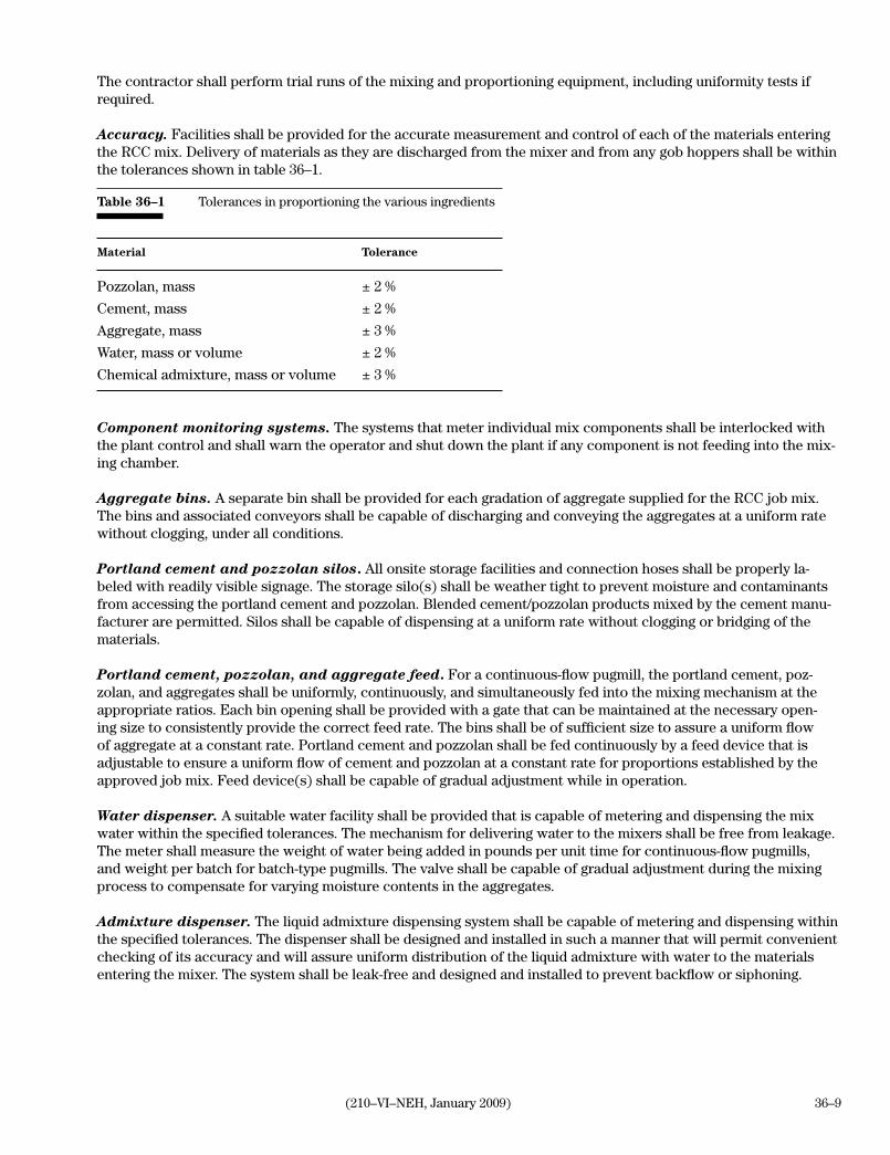
36–9(210–VI–NEH, January 2009)
The contractor shall perform trial runs of the mixing and proportioning equipment, including uniformity tests if required.
Accuracy. Facilities shall be provided for the accurate measurement and control of each of the materials entering the RCC mix. Delivery of materials as they are discharged from the mixer and from any gob hoppers shall be within the tolerances shown in table 36–1.
Table 36–1 Tolerances in proportioning the various ingredients
Material Tolerance
Pozzolan, mass ± 2 %
Cement, mass ± 2 %
Aggregate, mass ± 3 %
Water, mass or volume ± 2 %
Chemical admixture, mass or volume ± 3 %
Component monitoring systems. The systems that meter individual mix components shall be interlocked with the plant control and shall warn the operator and shut down the plant if any component is not feeding into the mix-ing chamber.
Aggregate bins. A separate bin shall be provided for each gradation of aggregate supplied for the RCC job mix. The bins and associated conveyors shall be capable of discharging and conveying the aggregates at a uniform rate without clogging, under all conditions.
Portland cement and pozzolan silos. All onsite storage facilities and connection hoses shall be properly la-beled with readily visible signage. The storage silo(s) shall be weather tight to prevent moisture and contaminants from accessing the portland cement and pozzolan. Blended cement/pozzolan products mixed by the cement manu-facturer are permitted. Silos shall be capable of dispensing at a uniform rate without clogging or bridging of the materials.
Portland cement, pozzolan, and aggregate feed. For a continuous-flow pugmill, the portland cement, poz-zolan, and aggregates shall be uniformly, continuously, and simultaneously fed into the mixing mechanism at the appropriate ratios. Each bin opening shall be provided with a gate that can be maintained at the necessary open-ing size to consistently provide the correct feed rate. The bins shall be of sufficient size to assure a uniform flow of aggregate at a constant rate. Portland cement and pozzolan shall be fed continuously by a feed device that is adjustable to ensure a uniform flow of cement and pozzolan at a constant rate for proportions established by the approved job mix. Feed device(s) shall be capable of gradual adjustment while in operation.
Water dispenser. A suitable water facility shall be provided that is capable of metering and dispensing the mix water within the specified tolerances. The mechanism for delivering water to the mixers shall be free from leakage. The meter shall measure the weight of water being added in pounds per unit time for continuous-flow pugmills, and weight per batch for batch-type pugmills. The valve shall be capable of gradual adjustment during the mixing process to compensate for varying moisture contents in the aggregates.
Admixture dispenser. The liquid admixture dispensing system shall be capable of metering and dispensing within the specified tolerances. The dispenser shall be designed and installed in such a manner that will permit convenient checking of its accuracy and will assure uniform distribution of the liquid admixture with water to the materials entering the mixer. The system shall be leak-free and designed and installed to prevent backflow or siphoning.

36–10 (210–VI–NEH, January 2009)
Mixing mechanism. The mixing mechanism shall be capable of combining the materials into a uniform mixture and discharging this mixture without segregation. The mixing mechanism shall produce a mix that meets the uni-formity requirements listed in table 36–2.
Uniformity tests. When a continuous-flow pugmill is used, the three samples for obtaining uniformity tests shall be taken from RCC produced near the beginning, the middle, and the end of a production run lasting a minimum of 1 minute. When a batch-type pugmill is used, the samples shall be taken from RCC produced from three separate batch-es. Each batch shall be similar in size, be produced by charging the mixer in a similar manner, be mixed at the same mixing speed and mix retention time as the other two batches, and be representative of a normal production run.
Table 36–2 Requirements for uniformity
Test Allowable max. ASTM standard difference 1/
Water content of full mix (% by weight) 10% C 566(Select one of the ASTM standard tests listed) D 2216 D 3017 D 4643 D 4959Coarse aggregate content (% by weight) 10% C 685 (annex)Density (lb/ft3) of full mix 2% C 1170, C 1176, C 1435Compressive strength at 14 days (lb/in2) 15% C 39 2/
1/ The allowable maximum difference = 100 multiplied by the (maximum value – minimum value) divided by the average of three tests.2/ Cylinders shall be made in accordance with ASTM Standard C 1176 or C 1435.
Mix record. The mix plant shall be capable of continually producing an RCC mix record. The record shall show the weight of portland cement, pozzolan, water, aggregate, and weight or volume of chemical admixture that is processed through the plant during a specific time interval. The time interval shall not exceed 30 minutes. The aggregate shall be reported in terms of saturated surface dry weight processed through the plant during a specific time interval. The RCC mix record shall be produced at all times when the plant is producing a mix. The aggregate moisture shall be tested daily whenever RCC is being produced. The mix plant record shall include the aggregate moisture content tests upon which the batch proportions are based.
A summary shift record shall be provided. The record shall include the total quantity of each constituent in the mix, total quantity of RCC produced, and a comparison of the quantity of each constituent mixed per cubic yard to that of the job mix.
Noise pollution. The plant shall be operated to comply with all applicable regulations pertaining to noise pollution.
Pollution control. The plant shall be operated to comply with all applicable regulations pertaining to air and water quality.
8. MixingThe plant shall be operated according to the manufacturer’s recommendations. The mixing mechanism shall be maintained in satisfactory operating condition and shall be cleaned after each production run. All supply bins and silos shall be kept sufficiently full to ensure a uniform and constant flow of all materials.

36–11(210–VI–NEH, January 2009)
All RCC produced from the beginning of startup shall be disposed of at the location(s) specified in section 22 of this specification until a uniform mix of the required proportions is consistently being discharged from the mixer.
After a batch-type pugmill has been calibrated and has produced the job mix with the specified uniformity, the mix retention time shall not be reduced.
Uniformity—RCC uniformity shall be monitored by continuous visual inspection by the plant operator and by pe-riodic visual inspection by contractor quality control personnel. The mix shall be visually inspected for uniformity by contractor quality control personnel at the beginning of each production run and at least once each hour during the production run. If it becomes apparent that the mixer is not producing a uniform mix of the proportions speci-fied, RCC production shall be promptly discontinued until the problem(s) that caused the uniformity problem are discovered and corrected.
If a uniformity problem is suspected, the contractor shall conduct the tests listed in table 36–2, determine the maxi-mum difference and compare to the allowable maximum difference, and take appropriate corrective measure(s).
Adjustments shall be made to the mixing plant as necessary to obtain the required uniformity and consistency of the RCC mix when uniformity test results indicate that the requirements for uniformity are not being met. The production and placement of RCC may proceed without waiting for the compressive strength results if the results of the other three tests listed in table 36–2 are within the allowable maximum difference and the issues that caused a uniformity problem are resolved.
9. Conveying The RCC mix shall be conveyed from mixer to placement area as rapidly as practicable by methods that prevent segregation, contamination, and loss of water. The total length of time from the end of mixing until the RCC has been placed, spread, and compacted shall not exceed 45 minutes.
The contractor shall provide baffles to limit free fall of mixed RCC to a maximum of 5 feet at the discharge end of conveyors, within hoppers, and at other locations where the potential for segregation may occur. Chutes that tend to cause segregation, such as an inclined chute, will not be permitted.
Communications—Telephone, radio, or other voice communication shall be provided between all interim stor-age hoppers, the batch plant control, and the placement locations. The contractor shall provide the Government inspector the same form of communication.
Temporary storage containers—Gob hoppers shall be used for storage wherever the mixed RCC is temporar-ily accumulated prior to being loaded into hauling equipment and when direct conveyor systems do not otherwise provide continuous delivery to the final placement location. Gob hoppers shall be configured to allow free flow of RCC without segregation or choking.
Conveyor belts—The conveyor system design and layout shall provide for adequate capacity, speed, reach, and pivot points to convey RCC to all placement areas.
Conveyor belts shall be designed, erected, operated, and maintained in a manner that meets production require-ments and does not segregate materials. RCC shall not be exposed on any belt for a period exceeding 5 minutes without being protected from the drying elements of wind and sun. RCC shall not be exposed on any belt during rainfall unless it is protected from the rain.
Hauling equipment—Equipment shall be maintained in good operating condition and shall not be permitted onto the RCC surface when vehicle fluids are leaking or when there is a potential for contamination to the RCC.

36–12 (210–VI–NEH, January 2009)
RCC may be hauled using trucks, front-end loaders, or scrapers. Hauling equipment that rut, score, mar, or indent the RCC surface shall not be operated directly on previously compacted RCC surfaces. Hauling equipment shall not track mud or other contaminants onto previously placed RCC and shall not be operated directly on uncompacted RCC. All hauling vehicles shall be operated in a manner that prevents tight turns, sudden stops, or other actions that cause damage or displacement to previously compacted RCC. The contractor shall implement necessary mea-sures to prevent contamination or damage of the previously compacted RCC.
10. WeatherAdverse weather—In adverse weather (heavy rain, severe cold, heavy snow, and hot temperature) where the conditions specified herein for RCC construction cannot be maintained, an interruption in placing operations shall be required.
Weather station—The contractor shall install and maintain a weather station onsite at all times during perfor-mance of the test section and the production and placement of RCC. The weather station shall be located at an approved location near the RCC structure. The weather station shall record wind speed, ambient temperature, humidity, and the rate and cumulative volume of rainfall. A record of climatic conditions at the designated location including wind speed, ambient temperature, humidity, and rainfall rate and volume shall be recorded daily.
Wet weather placement—RCC shall be protected from rainfall induced erosion and shall not be placed during rainfall events at a rate equal to or greater than 0.1 inch in 20 minutes. Placement during a light mist may continue when covered belt conveyors rather than hauling vehicles are used to convey the mix. Placement of RCC will not be permitted when rainwater accumulates on compacted RCC surfaces.
Cold weather placement—RCC shall not be placed when the ambient air temperature drops below 35 degrees Fahrenheit or the temperature of the RCC mix is less than 40 degrees Fahrenheit.
Hot weather placement—The maximum temperature of the RCC at time of placement shall be as specified in section 22. After placing, but prior to compaction, the temperature of the mix shall be determined according to ASTM C 1064. When the RCC temperature is within two degrees of the specified limit it shall be measured every hour. Introduction of chilled water and/or ice, shading and/or cooling of the aggregates, or other measures may be required in the production of RCC to maintain the RCC temperature within the specified requirements. If the RCC temperature exceeds the maximum specified temperature, RCC placement shall be suspended until cooler weather or additional measures to reduce the RCC temperature results in a reduction of the placement temperature of the RCC to or below the specified maximum temperature.
11. Foundation preparationPrior to the start of RCC placement, the foundation shall be excavated or filled to the specified lines and grades as shown on the drawings. The foundation shall be free of standing water and any organic or loose materials. All surfaces where RCC installation is specified shall be damp and have a surface temperature not less than 35 degrees Fahrenheit at time of placement. Placement of RCC on mud, dried earth, uncompacted fill, standing water, or fro-zen subgrade is not permitted.
Earthen foundations—Earthen foundation surfaces shall be prepared by adjusting the moisture content and compacting the foundation. The moisture content, depth, and degree of compaction required shall be as specified in section 22. If the earthen foundation is allowed to dry after compaction, it shall be moistened prior to placing RCC. The foundation surface shall be firm and damp.

36–13(210–VI–NEH, January 2009)
Rock foundations—Rock foundations shall be cleaned and prepared as specified in Construction Specification 63, Treatment of Rock Surfaces. The slope of the finished foundation surface shall not be steeper than one horizon-tal to one vertical. Rock surfaces shall be damp at the time of RCC placement.
12. Placing and spreadingThe placement of RCC into the structure shall be performed in a virtually continuous non-stop operation.
All equipment used on the RCC fill shall be maintained in good operating condition at all times. Equipment shall not drip or spill oil or other contaminants onto the RCC. Any equipment that contaminates the RCC mixture shall be promptly removed from contact with the RCC and repaired or replaced. Any contaminated RCC mixture shall be removed and replaced.
Placing and spreading shall be performed with equipment that does not mar or contaminate the surface of the com-pacted RCC. Track-type equipment shall not operate directly on compacted RCC unless the tracks are equipped with rubber pads. Equipment used to deposit, spread, or compact shall not turn on previously compacted RCC.
Layout of the placement area—The RCC shall be spread in level lifts across the entire area of the structure. The direction of RCC placement shall be parallel to the long axis of the structure so that the number of lanes and the number of edge joints are minimized. Transverse joints of adjacent lanes shall be offset by no less than 20 feet - horizontally.
Placing—RCC mix, bonding mortar, Portland cement, neat cement grout, or concrete shall not be placed on previ-ously placed layers that have not been compacted to the specified density.
Roller compacted concrete mix shall be deposited as near to its final location as possible. When haul vehicle deliv-ery is used, depositing shall be accomplished with a dump-spread action while the placing vehicle is moving. Belt placement shall discharge with a spreading action that does not segregate the material. RCC shall not be deposited directly against formwork or other vertical surfaces. Piles that form when placing RCC shall not contact forms or vertical surfaces. Neither the discharge height nor the pile height of RCC shall exceed 5 feet.
Spreading—Spreading of the RCC shall be completed within 10 minutes following depositing. RCC shall be spread into an uncompacted, uniform lift thickness that can be compacted to produce a lift of the specified thick-ness and density. In areas requiring special compaction, it may be necessary to deposit, spread, and compact the RCC in several layers to produce a lift of the specified thickness and density.
Equipment shall not operate directly on any surface that has been cleaned and prepared to receive a subsequent lift of RCC.
Spreading of RCC material shall be performed with a track-type bulldozer in a manner that will not cause damage to previously compacted RCC.
With RCC placement at or near its final location, spreading will typically be limited to leveling the RCC into uniform lifts. In isolated or confined placement locations, the RCC may be deposited and spread up to a maximum distance of 50 feet provided segregation does not occur, specified spreading time is not exceeded and the time specified be-tween mixing and a completion of compaction is not exceeded. The contractor shall conduct placing and spreading operations in a manner that will prevent segregation of RCC.
If segregation of RCC occurs during the spreading operation, it shall be corrected by immediately reworking the RCC. Reworking shall be performed using techniques that do not damage previously compacted RCC. This may require removing the RCC from the lift surface to accomplish reworking, then transporting the mix back onto the

36–14 (210–VI–NEH, January 2009)
surface after mix uniformity has been achieved. If reworking the RCC does not produce a uniform mix, the segre-gated RCC shall be wasted and replaced.
If a uniformity problem is suspected, uniformity tests shall be performed from material taken from the placement area following spreading of the material and/or other points in the RCC production process as required to identify the source of the problem. Three individual samples of the material shall be taken at the sample location at inter-vals of 5 minutes or more. Uniformity tests shall be conducted in accordance with table 36–2. The maximum differ-ence between the resulting values shall be compared to the allowable maximum difference and appropriate correc-tive measure(s) shall be employed.
13. CompactionThe entire surface area of each RCC lift shall be compacted to the specified density, as determined from the appar-ent maximum density (AMD) specified in section 6, with adequate compaction overlap to assure complete compac-tion of the RCC.
The in-place wet density of the compacted RCC measured at a depth of 10 inches shall not be less than 98 percent of the AMD.
Uniformity of density shall be achieved within each lift. The difference between density measurements at any two depths shall not exceed 2 percent of the greater of the two values.
The wet density of the compacted RCC shall be tested in accordance with ASTM C 1040. The moisture content of the compacted RCC shall be tested in accordance with ASTM D 3017. Unless otherwise specified in section 22, a minimum of three moisture and density tests will be performed on each lift of RCC with no less than one density measurement and moisture measurement for each 100 cubic yards of RCC compacted.
Production compaction shall be performed with production rollers as defined in this section. RCC compacted with production rollers shall be compacted in single lifts that are 12 inches thick (plus/minus one inch) after the speci-fied density has been achieved.
Production rollers shall consist of single or double drum, large, self-propelled vibratory rollers. The roller(s) shall transmit a centrifugal force to the surface through a smooth steel drum(s) by means of revolving weights, eccentric shafts, or other equivalent methods. Production rollers shall impart a centrifugal force of at least 450 pounds per inch of drum width at the operating frequency during compaction. Production rollers shall operate at a vibrating frequency of at least 1,500 vibrations per minute and have a drum diameter of 4 to 6 feet and a drum width of 5 to 8 feet. The amplitude of vibration of the roller shall be between 0.03 and 0.07 inch. The roller shall not travel at greater than 2 feet per second during the compaction operation.
Production rollers shall be used in open areas where they can compact RCC to the specified density within the specified time and without damage to the structure, forms, foundation, or appurtenances.
Rollers shall be only operated in the vibratory mode while actively compacting the RCC. After the RCC has been deposited and spread, rollers may be operated in static mode to smooth and/or firm up the surface, but shall oper-ate in the vibratory mode to compact the RCC to the specified density. Compaction shall be completed with the roller operated in the static mode, as necessary, to achieve the specified density near the surface of the lift.
36–15(210–VI–NEH, January 2009)
The contractor shall select the combination of frequency of vibration, amplitude of vibration, and speed of opera-tion that result in the specified density at the fastest production rate while meeting all other requirements.
Placement and compaction of RCC shall be completed without damaging the structure, other structures, forms, foundation, or other embedded appurtenances. Any appurtenance damaged by the compaction process will be repaired or removed and replaced at the contractor's expense.
Special compaction techniques shall be performed using special compaction rollers and power tampers in areas where production rollers cannot maneuver or will cause damage to the structure, forms, foundation, or appurte-nances. RCC shall be deposited, spread, and compacted in 4 or 6 inch thick layers as required to obtain uniform specified density throughout the 12-inch lift with limited compaction to avoid drying the surface.
The individual layers that compose one lift shall be deposited, spread, and compacted within 1 hour from the time the first layer within that lift is placed.
Special compaction rollers shall be vibratory rollers that are capable of operating in confined areas and adjacent to forms, foundation, or appurtenances without damage to the RCC structure or appurtenances. Special compac-tion rollers shall produce a centrifugal force of at least 150 pounds per linear inch of drum width for each drum of a double drum unit and 300 pounds per linear inch of drum width for a single drum unit. Special compaction rollers shall be operated at a speed less than 2 feet per second during the compaction operation.
Power tampers shall develop a force per blow of at least 3,500 pounds per square foot. The maximum layer thick-ness to be compacted by power tampers shall be plus or minus 6 inches after the specified density has been achieved.
The contractor shall maintain at least one special compaction roller and two tampers in operating condition at the site during RCC placement.
Manually directed vibratory plate compactors may be used to shape, smooth, and level the surface, but shall not be used as a substitute for vibratory rollers and power tampers.
14. Record testingUnless otherwise specified in section 22, one set of RCC cylinders for compressive strength tests shall be obtained for each 1,000 cubic yards of RCC placed to be used for compressive strength testing.
Each set shall consist of 15 compressive strength cylinders prepared in accordance with ASTM C 1176 or C 1435 and weighed to determine the density of the RCC within each cylinder. Any cylinder that weighs less than 98 per-cent of the weight of the heaviest cylinder shall be discarded and another cylinder prepared and weighed until all 15 cylinders have a weight that is at least 98 percent of that of the heaviest cylinder. Three cylinders shall be tested for compressive strength in accordance with ASTM C 39 at 7, 14, 28, 90, and 180 days, respectively, after the speci-mens are molded.
Unless otherwise specified in section 22 of this specification, the contractor shall extract two sets of vertical core RCC samples in accordance with ASTM C 42. Each set shall be sampled from RCC that has been placed in the structure at no less than 1 week apart. Each set shall contain eight intact cores taken from the structure at ap-proved locations. Cores shall have a minimum length equal to one lift thickness and a nominal diameter of 6 inches. Core specimens shall be obtained no earlier than 20 days after placement. The contractor shall test two samples at 28, 56, 90, and 180 days, respectively, after placement for compressive strength in accordance with ASTM C 42.

36–16 (210–VI–NEH, January 2009)
15. Lift jointsThe term joint, as used in this specification, applies to all surfaces that will eventually be covered by RCC mix, bonding mortar, Portland cement, neat cement grout, or conventional concrete.
The joint treatment method shall be as specified in section 22.
Joint condition—Three potential joint conditions will exist during construction: fresh joint, intermediate joint, and cold joint. The condition of a joint shall be defined on the basis of joint maturity or time of exposure. Joint ma-turity is defined as the product of the average RCC surface temperature (AST) in degrees Fahrenheit and the time of exposure (TE) in hours. Joint maturity is expressed in degree-hours (deg F-hr) and is calculated as:
——————>Joint maturity in deg F-hr = (AST) × (TE).
The TE shall be the period, expressed to the nearest quarter hour, beginning when the compaction of RCC is com-pleted and ending when covered by the subsequent placement of RCC, bonding mortar, Portland cement, neat cement grout, or conventional concrete.
Whenever the joint condition is defined on the basis of joint maturity, the AST shall be determined hourly during the exposure period by measuring the RCC surface temperature at various locations with a surface thermometer. The temperature shall be measured in degrees Fahrenheit and the temperature readings averaged to determine the AST.
A fresh joint is defined as a joint having maturity of 400 deg F-hr or less. In lieu of determining the joint maturity, a fresh joint may be defined as a joint with a TE of 4 hours or less.
An intermediate joint is defined as a joint having a maturity greater than 400 deg F-hr, but less than or equal to 1,600 deg F-hr. In lieu of determining the joint maturity, an intermediate joint may be defined as a joint with a TE of more than 4 hours, but less than 16 hours.
A cold joint is defined as a joint having a maturity of over 1,600 deg F-hr. In lieu of determining the joint maturity, a cold joint may be defined as a joint with a TE of 16 hours or more.
Joint treatment—All joint surfaces shall be kept continuously moist, clean, and uncontaminated until placement of succeeding RCC lifts. Water that ponds on a finished surface shall be removed prior to placing RCC.
The surface of previously placed RCC shall be free of soil, dust, or other contaminants prior to being covered with joint treatment material or another layer or lift of RCC. Cleaning of previously placed RCC lifts shall be ac-complished by pressurized water and/or air or other methods provided that the surface of the in-place layer is not damaged by the cleaning operation.
The contractor shall have a pressure washer and a blowpipe onsite capable of delivering a combined air-water mix-ture, with the ability to adjust the pressure, volume, and proportion of air and water.
Edge joints that are exposed for more than 30 minutes shall be trimmed back no less than 9 inches to an RCC surface, that has been compacted to the specified density and beveled at a slope of one horizontal to one vertical. Immediately before placing RCC against a trimmed surface, the joint condition shall be determined and the speci-fied joint treatment shall be applied.
Any surface to be covered with RCC, a bonding material or conventional concrete that is damaged to the extent that over 25 percent of the exposed coarse aggregate is undercut shall be treated as a cold joint. Coarse aggregate with less than half of it surface area remaining embedded and bonded to the RCC is considered undercut.

36–17(210–VI–NEH, January 2009)
All RCC materials removed by cleaning, brooming, smoothing, beveling, or trimming layers shall be collected and removed from the structure.
Treatment Method I. Remove any loose materials and contaminants from the lift joint surface. The lift joint surface shall be cleaned using moderate-pressure air immediately before spreading the next RCC lift. Maintain the surface in a moistened condition.
Treatment Method II. Perform Treatment Method I. Before the placement of RCC on the joint surface, uniformly distribute a layer of dry Portland cement over the surface. The Portland cement shall be applied at a rate of 0.5 to 1 pound per square foot of surface. The amount of water applied to the lift surface before, during, or after distrib-uting the cement shall be of sufficient quantity to dampen all of the cement. The ratio of water to cement shall be limited to that which will produce a tacky paste. Water applied after the cement is distributed shall be applied in a fine mist to prevent the displacement of cement. The cement shall be applied immediately ahead of placing the next layer or lift of RCC. The cement shall not be exposed on the surface more than 10 minutes before being cov-ered with RCC. Portland cement paste that does not meet these requirements shall be removed from the structure and disposed of, and the treatment method shall be repeated.
Treatment Method III. Perform Treatment Method I. Before the placement of RCC, the joint surface shall be covered with a layer of the bonding mortar specified in section 2. The thickness of the bonding mortar shall be 0.25 to 0.5 inch. The bonding mortar shall be covered with the next layer or lift of RCC while the mortar is still fluid. In no case shall the bonding mortar remain uncovered for more than 30 minutes. Bonding mortar shall be placed in a manner that will avoid segregation. Bonding mortar that does not meet these requirements shall be removed from the structure and disposed of, and the treatment method shall be repeated.
16. Curing and protectionCuring—Curing of RCC shall begin immediately after compaction. All exposed and completed RCC surfaces shall be cured for a minimum of 14 days at or above 40 degrees Fahrenheit following placement. All repairs including that required to fill holes associated with form anchorages and coring shall be cured for a minimum of 7 days at or above 40 degrees Fahrenheit following repair.
If the RCC is wet cured, the RCC shall be maintained in a continuously damp condition for the entire curing period. The continuous application of water supplemented by the use of a saturated cover material or an impermeable covering shall be required to obtain the continuously damp condition. The application of water or cover material shall not erode, mar, or otherwise damage the RCC. Plastic or paper covering shall meet the requirements of ASTM C 171. Only white or reflective coverings shall be used during hot weather as defined by ACI 305.
In lieu of wet curing, RCC that will not be covered with subsequent joint treatment, RCC, or conventional concrete may be treated with a curing compound as specified in section 2, unless otherwise specified in section 22. Areas to be cured with curing compound shall be kept continuously moist until curing compound is applied. Curing compound shall be thoroughly mixed before applying and be agitated during application. A continuously agitating pressure sprayer shall be used to apply the curing compound at a uniform rate of not less than double the curing compound manufacturer’s recommended rate for conventional concrete curing. Manual hand pump sprayers shall not be used. A brush or paint roller shall be used in areas that are near unmasked surfaces that will be covered with subsequent joint treatment, RCC, or conventional concrete. The curing compound shall form a uniform, con-tinuous, adherent film that shall not check, crack, or peel and shall be free from pinholes or other imperfections. Multiple applications of curing compound may be necessary to achieve the specified coverage. When multiple ap-plications are required, the second application shall be applied at a 90 degree angle to the first application. During

36–18 (210–VI–NEH, January 2009)
the curing period, curing compound shall be reapplied 7 days after the initial application. In areas where the curing compound is damaged, it shall be reapplied immediately.
Curing compound shall not be applied to areas that are to be repaired or patched. Areas to be repaired or patched shall be kept continuously moist until the repair is made. Curing compound or wet curing shall then be imple-mented to conform to curing requirements specified herein. Any curing compound applied to areas that are to be repaired or patched shall be removed prior to applying the repair material.
Regardless of the curing method used, curing activities shall not be discontinued or interrupted until the RCC has remained at or above 40 degrees Fahrenheit for a total of 14 days. This will require extending the curing period by the number of days that the RCC temperature drops below 40 degrees Fahrenheit during the curing period.
Protection—The temperature of RCC shall be maintained at or above 35 degrees Fahrenheit from the time the RCC is placed until 7 days after the curing period. When ambient temperatures are expected to be below 32 de-grees Fahrenheit, measures shall be implemented to protect the RCC from freezing. The protection shall remain in place until ambient temperatures remain continuously above 35 degrees Fahrenheit for 24 hours. Protective mea-sures shall not hinder the specified curing of the RCC.
RCC shall be protected from damage by precipitation, vehicular traffic, or other causes.
17. Vertical surfacesUnless otherwise specified in section 22, all formed RCC vertical surfaces that are subject to exposure shall be fin-ished to ensure a minimum of 80 percent of the surface area is free from honeycomb or other voids and is uniform in appearance.
Forming is not required for vertical RCC surfaces that are not subject to permanent exposure.
The finish and appearance of unformed vertical surfaces shall comply with the requirements specified in section 22.
18. TolerancesAny variation in the face or surface of the finished RCC shall be within the tolerances stated herein.
The structure(s) shall be constructed to the lines and grades depicted on the drawings.
The thickness of compacted lifts of RCC shall be 12 inches plus or minus 1 inch.
The allowable tolerance of all exposed formed surfaces shall be plus or minus 0.1 foot from specified line. Abrupt changes shall not exceed 0.05 foot in any exposed formed surface.
Limit gradual overbuild of exposed unformed RCC faces to 0.5 foot. Under build will not be allowed.
Do not exceed 0.1 foot in 10 feet variation in an unformed, exposed RCC face as measured in a straight line along the length and height of the face, or 0.5 foot over the entire length of the structure. Abrupt changes shall be less than 0.1 foot.
The elevation of any horizontal RCC surface shall be plus or minus 0.1 foot of the specified grade except that the elevation of a finished top of dam or spillway crest shall be no more than 0.1 foot above the specified elevation.
36–19(210–VI–NEH, January 2009)
19. Repair of RCCRepair or replacement—The contractor shall repair or replace RCC that does not meet the requirements of this specification. Before starting any repair or replacement work, the contractor shall prepare a written plan for the repair or replacement. The primary reference for material and repair methods for the plan shall be the appropriate sections of the American Concrete Institute’s Manual of Concrete Inspection. The repair plan shall be submitted for review and approval at least 10 days before any repair or replacement work.
Patching—All form bolts, metal ties, and similar forming restraints shall be removed to a depth of 1 inch below the surface of the RCC and their cavities repaired unless otherwise specifically permitted or specified in section 22. Small cavities large air holes, minor honeycombed areas, holes created from test coring, and other superficial imperfections that require patching to meet the specified finish requirement shall be thoroughly cleaned and filled. Holes left by bolts or straps that passes through the RCC shall be filled solid with a dense, well-bonded nonshrink patching material. Dry-pack mortar and replacement concrete shall follow the appropriate procedure detailed in the Repair and Maintenance chapter of the Concrete Manual, Bureau of Reclamation, U.S. Department of the Inte-rior. Proprietary patching material shall be appropriate for the type of repair used within the manufacturer's recom-mended limits and applied according to the manufacturer's recommendations.
When proprietary patching material is proposed in the plan, the manufacturer's data sheets and written recommen-dations shall be included in the plan.
Repair material or replacement concrete shall have properties, color, and texture similar to and compatible with the concrete being repaired or replaced.
Curing of repaired or replaced concrete shall be started immediately after finish work is completed as specified in section 16 or as specified by the manufacturer of proprietary compounds.
20. Cleanup of spillageAll loose gravel and uncompacted RCC material shall be removed from the structure for disposal in approved location(s) or as specified in section 22 and shall not be recycled into the RCC mix.
21. Measurement and paymentFor items of work for which specific unit prices are established in the contract, the volume of RCC is measured and computed to the nearest cubic yard by the method of average cross-sectional end areas. Unless otherwise specified in section 22, no deduction in volume is made for embedded items, such as, but not limited to conduits, inlet struc-tures, outlet structures, embankment drains, sand diaphragm and outlet, and their appurtenances.
The volume of RCC shall be determined by measuring from the surface of the foundation when approved for RCC placement to the specified neatlines of the completed RCC structures, unless otherwise specified in section 22.
If the test section is not incorporated into the RCC structure, the volume of RCC placed into the construction of the test section will be added to the volume computation of the completed RCC structure to determine the total volume of RCC for payment. If the test section is incorporated into the RCC structure, no addition volume of RCC shall be included for payment.
When the test section is paid for under a separate bid item, the test section will not be measured for payment. Pay-ment will be made at the contract lump sum price for the test section and will constitute full compensation for the completion of the test section including any removal and disposal as applicable.

36–20 (210–VI–NEH, January 2009)
Payment for the RCC, for which a specific unit price is established in the contract, will be computed to the near-est cubic yard. Payment shall constitute full compensation for furnishing all labor, materials (except cementitious materials), equipment, tools transportation, and all other items necessary and incidental to the construction and removal of the test section and construction of the RCC structure, including joint treatment, trimming and removal, repair, replacement, patching, curing, protection, site clean up, and disposal of spillage and waste materials. Pay-ment for treatment of rock foundation surfaces, if any, shall not be included in the payment for RCC. Payment will not be made for RCC material that is wasted or rejected for failure to comply with this specification.
Payment for each cementitious component of the RCC, for which a separate bid item is included in the contract, shall include the quantity incorporated into the RCC structure and test section. This quantity shall be computed based on statement of delivery tickets. Payment will not be made for any cementitious materials not incorporated into the structure(s) or test section.
Payment for the cementitious materials for which specific unit prices are established in the contract will be to the nearest 0.1 ton of cementitious materials.
Compensation for any item of work described in the contract, but not listed in the bid schedule will be included in the payment for the item of work to which it is made subsidiary. Such items and the items to which they are made subsidiary are identified in section 22.
22. Items of work and construction details

Part 642 National Engineering Handbook
National Standard Construction Specifications
Chapter 2
(210-VI-NEH, January 2009) 41–I–1
Instructions for useConstruction Specifications 41—Reinforced Concrete Pressure Pipe Conduits
1. ApplicabilityConstruction Specification 41 is applicable to the construction of principal spillway conduits appurte-nant to earth dams using bedded or cradled reinforced concrete pressure pipe. It may also be applied to the construction of any type of reinforced concrete pipe conduit that crosses under or through an earth dam or other deep earthfill.
2. Material specificationsThe following material specifications complement Construction Specification 41:535—Preformed Expansion Joint Filler 536—Sealing Compound for Joints in Concrete and Concrete Pipe541—Reinforced Concrete Pressure Pipe
Construction Specification 31, Portland Cement Con-crete for Bedding and Cradles, complements Construc-tion Specification 41.
3. Included itemsItems to be included in contract specifications and drawings follow:
a. Line and grade of the conduit. Include state-ment in items of work that pipe shall be laid so that there is no reversal of grade between joints unless shown on drawings.
b. Details of the pipe bedding or cradle, including joint details.
c. Excavation and backfill requirements, if appli-cable.
d. Pay limits or actual limits for excavation.
e. Details of wall fittings and other special pipe fittings.
f. Special requirements for foundation prepara-tion.
g. Type of pipe.
h. Size of pipe.
i. Strength of pipe in terms of three-edge bearing load and internal pressure.
j. Statement on acceptability for project use of pipe or pipe specimens tested in three-edge bearing test within the limits specified in Mate-rial Specification 541.
k. Maximum allowable offset in alignment of inte-rior pipe surface at joints, if tolerance is limited by cavitation hazard.
l. Method of pressure test selected. See item 4, Section 4, Pressure testing. Identify any vari-ance from ASTM C 924 for air test criteria.
m. Minimum joint length and minimum limiting angle of the joints according to definitions in Material Specification 541. Industry recommen-dation is to limit joint deflections to 1.5 inches.
n. Type and class of expansion joint filler.
o. Class of concrete for bedding or cradle and support blocks.
p. Statement that metal strips covering the joints as specified in section 4 are not required, if ap-plicable. (If the conduit rests on bedrock so no appreciable movement takes place at the joints, metal cover strips generally are not needed.)
4. MethodsSection 3, Laying the pipe
Method 1—The preferred method of stating the in-structions for connecting pipe sections.
Method 2—Intended for use when special problems are anticipated or when the pipe to be furnished re-quires special methods of connection.
Part 642 National Engineering Handbook
National Standard Construction Specifications
Chapter 2
(210-VI-NEH, January 2009)41–I–2
Section 4, Pressure testing
Method 1—Considered adequate for principal spill-way conduits that operate under pressure intermit-tently at normal frequencies.
Method 2—May be required for principal spillway conduits that operate under pressure for extended periods or at frequent intervals.
Method 3—May be required where water is at a pre-mium or unavailable; otherwise is not recommended because of potential size limitations and safety con-cerns.
Method 4—May be required for conduits that oper-ate under pressure when large pipe diameters or other project restraints make method 2 or 3, or both, diffi-cult, expensive or unsafe to test.
Section 6, Measurement and payment
Method 1—Must be used when it is desired to base payment on the measurement of the laid length of the conduit.
Method 2—Must be used when it is desired to base payment on the summation of the nominal laying lengths of the pipe sections used.
Sections 3, 4, and 6
When specifications are prepared using electronic pro-cedures and all methods but one are deleted for use in a contract specification, delete from the last paragraph All Methods The following provisions apply to all methods of measurement and payment. Left justify the remaining text.
5. Items of work and construction detailsStarting at the top of page 41–3, prepare and outline job specific "Items of Work and Construction Details" (IWCD) in accordance with these instructions.

41–1(210–VI–NEH, May 2001)
Construction Specification 41—Reinforced Concrete Pressure Pipe Conduits1. ScopeThe work shall consist of furnishing and installing reinforced concrete pressure pipe conduits, fittings, and acces-sories as shown on the drawings and/or specified herein.
2. MaterialReinforced concrete pressure pipe, fittings, and accessories shall conform to the requirements of Material Specification 541, Reinforced Concrete Pressure Pipe.
Portland cement concrete for bedding and cradles shall conform to the requirements of Construction Specifi-cation 31 for the specified class of concrete.
Joint sealing compound shall conform to the requirements of Material Specification 536, Sealing Compound for Joints in Concrete and Concrete Pipe.
Preformed expansion joint filler shall conform to the requirements of Material Specification 535, Preformed Expansion Joint Filler.
Filter fabric shall conform to Material Specification 592, Geotextile.
Portland cement concrete for bedding and cradles shall conform to Construction Specification 31.
3. Laying the pipe
The pipe shall be set to the specified line and grade and temporarily supported on precast concrete blocks or wedges. Concrete blocks and wedges used to temporarily support the pipe during placement of concrete bedding or cradle, or both, shall be a class of concrete equal to or stronger than the concrete used to construct the bedding or cradle. Bell and spigot pipe shall be laid with the bells or grooves facing upstream unless otherwise specified in section 7 or shown on the drawings. When precast pipe risers and other similar precast pipe structures are installed before pipe installation, pipe may be installed in the downstream direction with the belled end upstream. Adequate bell clearance in the subgrade/bedding shall be provided.
Just before each joint is connected, the connecting surface of the bell and spigot or spigots and sleeve shall be thoroughly cleaned and dried. Also, the rubber gasket and the inside surface of the bell or sleeve shall be lubricated with a light film of soft vegetable soap compound (flax soap). The rubber gasket shall be stretched uniformly as it is placed in the spigot groove to ensure a uniform volume of rubber around the circumference of the pipe.
Method 1—The joint shall be connected by means of a pulling or jacking force so applied to the pipe that the spigot enters squarely into the bell.
Method 2—The joint shall be connected in accordance with the manufacturer's instructions.
Use with either method—When the spigot has been seated to within 0.5 inch of its final position, the position of the gasket in the joint shall be checked around the entire circumference of the pipe by means of a metal feeler gauge. In any case where the gasket is found to be displaced, the joint shall be disengaged and properly recon-nected. After the position of the gasket has been checked, the spigot shall be completely pulled into the bell and the section of pipe shall be adjusted to line and grade.

41–2 (210–VI–NEH, May 2001)
4. Filling jointsBefore the placement of the bedding or cradle, the exterior annular space between the ends of the pipe sections shall be cleaned and completely filled with joint sealing compound. Before the compound is applied, the surface against which it is to be placed shall be cleaned of all dust, lubricant, and other substances that would interfere with a bond between the compound and the pipe. If recommended by the manufacturer of the compound, the con-crete surface shall be coated with a primer in accordance with the manufacturer's recommendations. Primers shall be applied to the concrete surface only and shall not come in contact with the gasket or gasket sealing surface. Un-less the compound or primer is specifically recommended for use on moist concrete, the surface shall be dry when the compound or primer is applied.
The joint sealing compound shall be allowed to cure until it is sufficiently firm to prevent the entry of concrete or earth into the joint. Unless otherwise specified in section 7 of this specification, before placing bedding or earth backfill (excluding concrete) containing particles larger than 0.25 inch in maximum dimension within 6 inches of the joint sealing compound, the compound shall be covered with a strip of 16-gauge to 24-gauge metal at least 2-inches wider than the space between the ends of the pipe sections. Instead of metal strips, the joints shall be covered by a minimum of 2-foot-wide, 4-ply thick filter fabric. Filter fabric shall be wrapped completely around the joint and overlapped a minimum of 12 inches at the top of the pipe. Lap shall be securely fastened to ensure filter fabric fits snugly during backfill operations. Filter fabric is centered on the joint. It shall conform to Material Speci-fication 592, table 2, Nonwoven, class II.
5. Pressure testingMethod 1—Pressure testing of the completed conduit is not required.
Method 2—Before placing any concrete or earthfill around the conduit or filling the pipe joints, the conduit shall be tested for leaks in the following manner:
The ends of the conduits shall be plugged and a standpipe with a minimum diameter of 2 inches shall be attached to the upstream plug. The conduit shall be braced at each end to prevent slippage. The conduit and the standpipe shall be filled with water. The water level in the standpipe shall be maintained at least 10 feet above the invert of the upstream end of the conduit for at least 2 hours. Any leaks shall be repaired, and the conduit shall be tested again as described. The procedure shall be repeated until the conduit is watertight.
The pipe joints shall show no leakage. Damp spots developing on the surface of the pipe are not considered as leakage.
Method 3—Before placing any concrete or earthfill around the conduit or filling the pipe joints, the conduit shall be air tested in accordance with ASTM C 924. The conduit shall be braced on each end to prevent slippage. All end plugs used for the air test shall be capable of resisting the internal pressure and must be securely braced.
All testing equipment to be used shall be furnished by the contractor and shall be inspected and approved by the engineer. The pressure gauges used shall be graduated to read in increments of 0.1 pounds per square inch and cali-brated to provide accuracy within 10 percent plus or minus of the standard gauge. The contractor has the option of prewetting the conduit or line before testing. Any conduit that fails to pass this test must be repaired by a method satisfactory to the engineer. After the repairs are made, the conduit shall be retested until it passes the test require-ments.

41–3(210–VI–NEH, May 2001)
Method 4—Before placing concrete or earth backfill around the conduit joint to be tested or filling the pipe joints, the joint shall be tested in accordance to ASTM C 1103, Standard Practice for Joint Acceptance Testing of Installed Precast Concrete Sewer Line. The test pressure shall be as specified in section 7 of this specification. Any joints showing leaks shall be relaid or repaired, and the joint shall be retested. The procedure shall be repeated until the joint passes the test.
6. Measurement and paymentMethod 1—For items of work for which specific unit prices are established in the contract, the quantity of each size, type, and class of pipe is determined to the nearest 0.l foot by measurement of the laid length of pipe along the invert centerline of the conduit. Payment for each size, type, and class of reinforced concrete pressure pipe is made at the contract unit price for that size, type, and class of pipe. Such payment constitutes full compensation for fur-nishing, transporting, and installing the pipe complete in place. This includes accessories, such as wall fittings, joint gaskets, coupling bands, sleeves, or collars, and all other items necessary and incidental to the completion of the work except the special fittings and appurtenances listed separately in the bid schedule. Payment for each special fitting and appurtenance is made at the contract price for that type and size of fitting or appurtenance.
Method 2—For items of work for which specific unit prices are established in the contract, the quantity of each size, type, and class of pipe is determined as the sum of the nominal laying lengths of the pipe sections used. Pay-ment for each size, type, and class of reinforced concrete pressure pipe is made at the contract unit price for that size, type, and class of pipe. Such payment constitutes full compensation for furnishing, transporting, and installing the pipe complete in place. This includes accessories, such as wall fittings, joint gaskets, coupling bands, sleeves or collars, and all other items necessary and incidental to the completion of the work except the special fittings and appurtenances listed separately in the bid schedule. Payment for each special fitting and appurtenance is made at the contract price for that type and size of fitting and appurtenance.
All Methods—The following provisions apply to all methods of measurement and payment. Compensation for any item of work described in the contract, but not listed in the bid schedule, is included in the payment for the item of work to which it is made subsidiary. Such items and the items to which they are made subsidiary are identified in section 7 of this specification.
7. Items of work and construction details

Part 642 National Engineering Handbook
National Standard Construction Specifications
Chapter 2
(210-VI-NEH, May 2001)41–4

Part 642 National Engineering Handbook
National Standard Construction Specifications
Chapter 2
(210-VI-NEH, January 2009) 42–I–1
Instructions for useConstruction Specifications 42—Concrete Pipe Conduits and Drains
1. ApplicabilityConstruction Specification 42 is applicable to all con-crete pipe conduits except principal spillway conduits for earth dams or conduits under deep fills. It may be applied to culverts, pipe collector systems in structure drains, irrigation pipelines, or parts of land drainage systems.
2. Material specificationsThe following material specifications complement Construction Specification 42:535—Preformed Expansion Joint Filler 536—Sealing Compound for Joints in Concrete and Concrete Pipe541—Reinforced Concrete Pressure Pipe 542—Concrete Culvert Pipe 543—Nonreinforced Concrete Pipe (concrete irrigation pipe, drainage pipe, and drain tile)
Portland cement concrete for bedding and cradles shall conform to Construction Specification 31, Con-crete for Major Structures, or Construction Specifica-tion 32, Structure Concrete.
3. Included itemsItems to be included in contract specifications and drawings follow:
a. Line and grade of the conduit. Include state-ment in section 11 that pipe shall be laid so that there is no reversal of grade between joints unless shown on the drawings.
b. Details of concrete bedding or cradle, includ-ing class of concrete, joint details, and type of expansion joint filler.
c. Details of earth, sand, or gravel bedding, in-cluding description and grading limits of the bedding material.
d. Excavation and backfill requirements, if appli-cable.
e. Pay limits or actual limits for excavation and backfill, if required.
f. Special requirements for foundation prepara-tion.
g. Kind of pipe or tile by name and class. (See ap-propriate reference specifications.)
h. Size of pipe or tile.
i. Type of cement for pipe or tile if a certain type is necessary because of soil, water, or other environmental conditions.
j. Strength of pipe, if not covered by reference specifications, in terms of three-edge-bearing load and internal pressure as appropriate.
k. Type of joint and details of banded joints or other special joints.
l. Details of wall fittings and other special fittings and appurtenances.
m. Test pressure, if applicable.
n. Method of measurement and payment if the standard specification includes more than one method.
4. MethodsSection 5a, Rubber gasket joint, pressure pipe
Method 1—The preferred method of stating the in-structions for connecting pipe sections.
Method 2—Intended for use when special problems are anticipated or when the pipe to be furnished re-quires special methods of connection.
Section 9, Pressure testingThe methods are self-explanatory. The choice of method must be consistent with the function of the conduit and the required operating pressure.

Part 642 National Engineering Handbook
National Standard Construction Specifications
Chapter 2
(210-VI-NEH, January 2009)42–I–2
Section 10, Measurement and paymentMethod 1—Must be used when it is desired to base payment on the measurement of the laid length of the conduit.
Method 2—Must be used when it is desired to base payment on the summation of the nominal laying lengths of the pipe sections used.
Sections 5a, 9, and 10When specifications are prepared using electronic pro-cedures and all methods but one are deleted for use in a contract specification, delete from the last para-graph All Methods The following provisions apply to all methods of measurements and payment. Left justify the remaining text.
5. Items of work and construction detailsStarting at the top of page 42–5, prepare and outline job specific "Items of Work and Construction Details" (IWCD) in accordance with these instructions.
42–1(210–VI–NEH, May 2001)
Construction Specification 42—Concrete Pipe Conduits and Drains
1. ScopeThe work shall consist of furnishing and installing concrete pipe or concrete drain tile and the necessary fittings as shown on the drawings.
2. MaterialReinforced concrete pressure pipe shall conform to the requirements of Material Specification 541, Reinforced Concrete Pressure Pipe, for the type and strength specified.
Concrete culvert pipe shall conform to the requirements of Material Specification 542, Concrete Culvert Pipe, for the kind of pipe specified.
Concrete irrigation pipe, drainage pipe, and drain tile shall conform to the requirements of Material Specifi-cation 543, Nonreinforced Concrete Pipe, for the kind of pipe or tile specified.
Pipe fittings shall conform to the requirements of the applicable pipe specifications.
Sealing compound for filling rubber gasket joints shall conform to the requirements of Material Specification 536, Sealing Compound for Joints in Concrete and Concrete Pipe.
Hot-pour joint sealer shall conform to the requirements of Material Specification 536, Sealing Compound for Joints in Concrete and Concrete Pipe.
Cold-applied sealing compound shall conform to the requirements of Material Specification 536, Sealing Com-pound for Joints in Concrete and Concrete Pipe.
Preformed sealing compound shall conform to the requirements of Material Specification 536, Sealing Com-pound for Joints in Concrete and Concrete Pipe.
Joint packing shall be commercial grade oakum.
Preformed expansion joint filler shall conform to the requirements of Material Specification 535, Preformed Expansion Joint Filler.
Portland cement concrete for bedding and cradles shall conform to Construction Specification 31, Concrete for Major Structures, or Construction Specification 32, Structure Concrete.
3. Laying and beddingPipe and tile shall be laid to the line and grade shown on the drawings. Unless otherwise specified, belled pipe shall be laid with the bells or grooves facing upstream. When precast pipe risers and other similar precast pipe struc-tures are installed before pipe installation, pipe may be installed in the downstream direction with the belled end upstream. Adequate bell clearance in the subgrade/bedding shall be provided.
Concrete cradles or bedding—Pipe to be cradled or bedded on concrete shall be set to the specified line and grade and temporarily supported on precast concrete blocks or wedges until the cradle or bedding concrete is placed. Concrete blocks or wedges used to temporarily support the pipe during placement of bedding or cradle shall be of a class of concrete equal to or stronger than that to be used in the bedding or cradle.
42–2 (210–VI–NEH, May 2001)
Earth, sand, or gravel bedding—The pipe shall be uniformly bedded throughout its entire length to the depth and in the manner specified on the drawings. The pipe shall be loaded sufficiently during backfilling around the sides to prevent displacement.
Perforated pipe shall be laid with the perforations down and oriented symmetrically about a vertical centerline. Perforations shall be clear of any obstructions when the pipe is laid.
Elliptical pipe and pipe with elliptical or quadrant reinforcement shall be laid so that the vertical axis, as indicated by markings on the pipe, is in a vertical position.
4. JointsPipe joints shall conform to the details shown on the drawings and to the requirements of sections 5 and 6 of this specification applicable to the type of joint specified. Except where unsealed joints are indicated, pipe joints shall be sound and watertight at the pressure specified.
5. Jointing bell and spigot pipeRubber gasket joint, pressure pipeJust before the joint is connected, the connecting surfaces of the spigot and the bell or coupling band, sleeve, or collar shall be thoroughly cleaned and dried. Also, the rubber gasket and the inside surface of bell or coupling band, sleeve, or collar shall be lubricated with a light film of soft vegetable soap compound (flax soap). The rubber gasket shall be stretched uniformly as it is placed in the spigot groove to ensure a uniform volume of rubber around the circumference of the pipe.
Method 1—The joint shall be connected by means of a pulling or jacking force so applied to the pipe that the spigot enters squarely into the bell.
Method 2—The joint shall be connected in accordance with the manufacturer's recommendations.
Use with either method—When the spigot has been seated to within 0.5 inch of its final position, the position of the gasket in the joint shall be checked around the entire circumference of the pipe using a metal feeler gauge. In any case where the gasket is found to be displaced, the joint shall be disengaged and properly reconnected. After the proper position of the gasket has been confirmed, the spigot shall be completely pulled into the bell and the section of the pipe shall be adjusted to line and grade.
Rubber gasket joints, sewer, and culvert pipe or irrigation pipeThe pipe shall be joined in accordance with the gasket manufacturer's recommendations except as otherwise specified.
Mastic sealed jointsAt the time of assembly, the inside surface of the bell and the outside surface of the spigot shall be clean, dry, and primed as recommended by the manufacturer of the sealing compound. A closely twisted gasket of joint packing of the diameter required to support the spigot at the proper grade and to make the joint concentric shall be made in one piece of sufficient length to pass around the pipe and lap at the top. The gasket shall be laid in the bell through-out the lower third of the circumference. The end of the spigot shall be laid in the bell throughout the lower third of the circumference. The end of the spigot shall be laid on the gasket, and the spigot shall be fully inserted into the bell so that the pipe sections are closely fitted and aligned. The gasket then shall be lapped at the top of the pipe and thoroughly packed into the annular space between the bell and the spigot.
Hot-pour joint sealer—The sealing compound shall be heated to within the temperature range recommended by the manufacturer and shall not be overheated or subjected to prolonged heating. After the joint is assembled with the pipe in its final location, a suitable joint runner shall be placed around the joint with an opening left at the top.

42–3(210–VI–NEH, May 2001)
Molten sealing compound shall be poured into the joint as rapidly as possible without entrapping air until the an-nular space between bell and spigot is completely filled. After the compound has set, the runner may be removed. Alternate joints may be poured before the pipe is lowered into the trench. In this case the joint shall be poured with the pipe in a vertical position without the use of the runner. The compound shall have thoroughly set before the pipe is placed in the trench, and the pipe is handled so as to cause no deformation of the joint during placement.
Cold-applied sealing compound—The annular space between bell and spigot shall be completely filled with the sealing compound. The compound shall be mixed on the job in accordance with the manufacturer's recommenda-tions and in relatively small quantities so that setting will not be appreciable before application.
Preformed sealing compound—Joint packing is not required except as recommended by the manufacturer of the sealing compound. Preformed strips or bands of the sealing compound shall be applied to the bell and spigot be-fore assembly of the joint in accordance with the manufacturer's recommendations. Any compound extruded from the interior side of the joint during assembly shall be trimmed even with the interior surface of the pipe.
Cement mortar sealed jointsCement mortar for joints shall consist of one part by weight of portland cement and two parts by weight of fine sand with enough water added to produce a workable consistency. At the time of assembly, the inside surface of the bell and the outside surface of the spigot shall be clean and moist.
With packing—A closely twisted gasket of joint packing of the diameter required to support the spigot at the proper grade and to make the joint concentric shall be made in one piece of sufficient length to pass around the pipe and lap at the top. The gasket shall be saturated with neat cement grout, laid in the bell throughout the lower third of the circumference, and covered with mortar. The end of the spigot shall be fully inserted into the bell so that the pipe sections are closely fitted and aligned. A small amount of mortar shall be placed in the annular space throughout the upper two-thirds of the circumference. The gasket then shall be lapped at the top of the pipe and thoroughly packed into the annular space between the bell and the spigot. The remainder of the annular space then shall be filled completely with mortar and beveled off at an angle of about 45 degrees with the outside of the bell. If the mortar is not sufficiently stiff to prevent appreciable slump before setting, the outside of the joint thus made shall be wrapped with cheesecloth. After the mortar has set slightly, the joint shall be wiped inside the pipe. If the pipe is too small for a person to work inside, wiping may be done by dragging an approved swab through the pipe as the work progresses.
Without packing—The lower part of the bell shall be filled with stiff mortar of sufficient thickness to make the in-ner surface of the abutting sections flush. The spigot end of the pipe to be joined shall be fully inserted into the bell so that the sections are closely fitted and aligned. The remaining annular space between the bell and spigot shall then be filled with mortar and the mortar neatly beveled off at an angle of about 45 degrees with the outside of the bell. After the mortar has set slightly, the joint shall be wiped inside the pipe. If the pipe too small for a person to work inside, wiping may be done by dragging an approved swab through the pipe as the work progresses.
Unsealed jointsWhen unsealed joints are specified, they shall conform to the details shown on the drawings.
6. Joining tongue and groove pipeCement mortar sealed jointMortar shall be as specified for bell and spigot joints. The tongue end of the section being placed shall be covered with mortar and firmly pressed into the groove of the laid section so that the tongue fits snugly and truly in the
42–4 (210–VI–NEH, May 2001)
groove and that mortar is squeezed out on both the interior and exterior of the joint. Care shall be taken that no mortar falls from the groove end during the abutting operation. Immediately after the pipe sections have been abutted, exposed external surface mortar shall be pressed into the joint and any excess mortar removed. After this is done, the interior surface of the joint shall be carefully pointed and brushed smooth and all surplus mortar removed.
Mastic sealed jointsStrips or bands of preformed sealing compound shall be applied to the tongue and groove before assembly of the joint in accordance with the manufacturer's recommendations. Any compound extruded from the interior side of the joint during assembly shall be trimmed even with the interior surface of the pipe.
Rubber gasket jointsThe pipe shall be joined in accordance with the gasket manufacturer's recommendations except as otherwise specified.
Unsealed jointsWhen unsealed joints are specified, they shall conform to the details shown on the drawings.
7. BandingWhen external mortar bands are specified, they shall conform to the details shown on the drawings.
8. Curing mortar joints and bandsThe external surface of mortar joints shall be covered with moist earth, sand, canvas, burlap, or other approved material and shall be kept moist for 10 days or until the pipe is backfilled. Earth backfilling operations shall not begin until 24 hours after joints are finished.
Water shall not be turned into the conduit within 24 hours after the joints are finished. Hydrostatic pressure shall not be applied to the conduit before 14 days after the joints are finished.
9. Pressure testingMethod 1—Pressure testing of the completed conduit is not required.
Method 2—Before the concrete or earth backfill is placed around the conduit, the conduit shall be tested for leaks in the following manner:
The ends of the conduits shall be plugged and a standpipe with a minimum diameter of 2 inches shall be attached to the upstream plug. The conduit shall be braced at each end to prevent slippage. The conduit and the standpipe shall be filled with water. The water level in the standpipe shall be maintained a minimum of 10 feet above the invert of the upstream end of the conduit for a period of not less than 2 hours. Any leaks shall be repaired and the conduit shall be retested as described. The procedure shall be repeated until the conduit is watertight.
Method 3—Before the concrete or earth backfill is placed around the conduit, the conduit shall be tested at the specified test pressure for a period of at least 2 hours. Any leaks shall be repaired, and the conduit shall be retest-ed. The procedure shall be repeated until the conduit is watertight.
Method 4—Before the concrete or earth backfill is placed around the conduit joint to be tested, the joint shall be tested in accordance to ASTM C 1103, Standard Practice for Joint Acceptance Testing of Installed Precast Concrete Pipe Sewer Lines. Any joints showing leaks shall be relaid or repaired, and the joint shall be retested. The proce-dure shall be repeated until the joint passes the test.

42–5(210–VI–NEH, May 2001)
For methods 2, 3, and 4, the pipe joints shall show no leakage. Damp spots developing on the surface of the pipe are not considered leaks.
10. Measurement and paymentMethod 1—For items of work for which specific unit prices are established in the contract, the quantity of each kind, size, and class of pipe or tile is determined to the nearest 0.l foot by measurement of the laid length along the invert centerline of the conduit. Payment for each kind, size, and class of pipe or tile is made at the contract unit price for that kind, size, and class. Such payment constitutes full compensation for furnishing, transporting, and installing the pipe or tile complete in place.
Method 2—For items of work for which specific unit prices are established in the contract, the quantity of each kind, size, and class of pipe or tile is determined as the sum of the nominal laying lengths of the sections used. Payment for each kind, size, and class of pipe or tile is determined as the sum of the nominal laying lengths of the sections used. Payment for each kind, size, and class of pipe or tile is made at the contract unit price for that kind, size, and class. Such payment constitutes full compensation for furnishing, transporting, and installing the pipe or tile complete in place.
All methods—The following provisions apply to all methods of measurement and payment. Compensation for any item of work described in the contract, but not listed in the bid schedule, is included in the payment for the item of work to which it is made subsidiary. Such items and the items to which they are made subsidiary are identified in section 11 of this specification.
11. Items of work and construction details

Part 642 National Engineering Handbook
National Standard Construction Specifications
Chapter 2
(210-VI-NEH, May 2001)42–6

Part 642 National Engineering Handbook
National Standard Construction Specifications
Chapter 2
(210-VI-NEH, January 2009) 43–I–1
Instructions for useConstruction Specifications 43—Clay Pipe
1. ApplicabilityConstruction Specification 43 is applicable to all types of clay pipe conduits. Application to pipe collector systems in structure drains or to parts of land drainage systems is applicable.
2. Material specificationsThe following material specifications complement Construction Specification 43:536—Sealing Compound for Joints in Concrete and Concrete Pipe 544—Clay Pipe and Drain Tile
3. Included itemsItems to be included in contract specifications and drawings follow:
a. Line and grade of the conduit. Include state-ment in items of work that pipe shall be in-stalled in a manner that no reversal of grade between joints occurs unless shown on the drawings.
b. Details of the bedding including description and grading limits of the bedding material.
c. Excavation and backfill requirements, if appli-cable.
d. Pay limits or actual limits for excavation and backfill, if required. When excavation require-ments need to be performed to comply with safety requirements, state clearly if those vol-umes are included or not in the pay limits.
e. Kind and class of pipe or tile.
f. Size(s) of pipe or tile.
g. Type of joint and details of special joints.
h. Details of wall fittings and other special fittings and appurtenances.
i. Pressure testing requirements, if applicable.
j. Method of measurement and payment if the standard specification includes more than one method.
4. MethodsSection 6, Measurement and payment
Method 1—Must be used when it is desired to base payment on the measurement of the laid length of the conduit.
Method 2—Must be used when it is desired to base payment on the summation of the nominal laying lengths of the pipe conduit.
When specifications are prepared using electronic procedures and all measurement and payment meth-ods but one are deleted for use in a contract specifi-cation, delete from the last paragraph, All Methods The following provisions apply to all methods of measurement and payment. Left justify the remain-ing text.
5. Items of work and construction detailsStarting at the top of page 43–3, prepare and outline job specific "Items of Work and Construction Details" (IWCD) in accordance with these instructions.

Part 642 National Engineering Handbook
National Standard Construction Specifications
Chapter 2
(210-VI-NEH, January 2009)43–I–2

43–1(210–VI–NEH, May 2001)
Construction Specification 43—Clay Pipe
1. Scope
The work consists of furnishing and installing clay pipe and/or clay drain tile and the necessary fittings as shown on the drawings.
2. MaterialPipe, drain tile, and fittings shall conform to the requirements of Material Specification 544, Clay Pipe and Drain Tile, for the kind of pipe or tile specified.
Sealing compound for filling rubber gasket joints shall conform to the requirements of Material Specification 536, Sealing Compound for Joints in Concrete and Concrete Pipe.
Compression joints using resilient material shall conform to the requirements of ASTM C 425.
Nonpour joint sealer shall conform to the requirements of Material Specification 536, Sealing Compound for Joints in Concrete and Concrete Pipe.
Cold-applied sealing compound shall conform to the requirements of Material Specification 536, Sealing Com-pound for Joints in Concrete and Concrete Pipe.
Joint packing shall be commercial grade oakum.
3. Laying and beddingPipe and tile shall be installed to the line and grade shown on the drawings. Each pipe section shall be installed with the bell end upstream.
The pipe shall be firmly and uniformly bedded throughout its entire length to the depth and in the manner specified on the drawings. The pipe shall be loaded sufficiently during backfilling around the sides to prevent uplift of the pipe and the development of voids between the pipe and bedding.
Perforated pipe and tile shall be laid with the perforations down and oriented symmetrically about the vertical centerline. Perforations shall be clear of any obstructions when the pipe is installed.
4. JointsPipe joints shall conform to the details shown on the drawings except where unsealed joints are indicated. The joints shall be sound and watertight at the pressures specified.
Rubber gasket joints shall be assembled in accordance with the gasket manufacturer's recommendations except as otherwise specified.
Compression joints using resilient material shall be assembled in accordance with the manufacturer's recom-mendations.
Mastic sealed joints—At the time of pipe assembly, the inside surface of the bell and the outside surface of the spigot shall be clean, dry, and primed as recommended by the manufacturer of the sealing compound. A closely twisted gasket of joint packing, of the diameter required to support the spigot at the proper grade and to make the joint concentric, shall be made in one piece of sufficient length to pass around the pipe and lap at the top of the pipe and be thoroughly packed into the annular space between the bell and the spigot.

43–2 (210–VI–NEH, May 2001)
Hot-pour joint sealer—The sealing compound shall be heated to within the temperature range recom-mended by the manufacturer and shall not be overheated or subjected to prolonged heating. After the joint is assembled, with the pipe in its final location, a suitable joint runner shall be placed around the joint with an opening left at the pipe top. Molten sealing compound shall be poured into the joint as rapidly as pos-sible without entrapping air until the annular space between bell and spigot is completely filled. After the compound has set, the runner may be removed. Alternate joints may be poured before the pipe is lowered into the trench. When this installation procedure is used, the joint shall be poured with the pipe in a vertical position without the use of a runner. The compound shall have thoroughly set before the pipe is placed in the trench, and the pipe shall be handled so as to cause no deformation of the joint during placement.
Cold-applied sealing compound—The annular space between bell and spigot shall be completely filled with the sealing compound. The compound shall be mixed on the job in accordance with the manufacturer's recommendations and in relatively small quantities so that setting is not appreciable before application.
Preformed sealing compound—Joint packing is not required except as recommended by the manufacturer of the sealing compound. Preformed strips or bands of the sealing compound shall be applied to the bell and spigot before assembly of the joint in accordance with the manufacturer's recommendations. Any com-pound extruded from the interior side of the joint during assembly shall be trimmed even with the interior surface of the pipe.
Cement mortar sealed joints—Cement mortar for joints shall consist of one part, by weight, of portland cement and two parts, by weight, of fine sand with adequate water added to produce a workable consistency. At the time of assembly, the inside surface of the bell and the outside surface of the spigot shall be clean and moist.
With packing. A closely twisted gasket of joint packing, of the diameter required to support the spigot at the proper grade and to make the joint concentric, shall be made in one piece of sufficient length to pass around the pipe and lap at the pipe top. The gasket shall be saturated with neat cement grout, laid in the bell throughout the lower third of the circumference, and covered with mortar. The end of the spigot shall be fully inserted into the bell so that the pipe sections are closely fitted and aligned. A small amount of mortar shall be placed in the annular space throughout the upper two-thirds of the circumference. The gasket then shall be lapped at the top of the pipe and thoroughly packed into the annular space between the bell and the spigot. The remainder of the annular space shall then be filled completely with mortar and beveled off at an angle of about 45 degrees with the outside of the bell. If the mortar is not sufficiently stiff to prevent appre-ciable slump before setting, the outside of the joint thus made shall be wrapped with cheesecloth. After the mortar has set slightly, the joint shall be wiped inside the pipe. If pipe is too small for a person to work in-side, wiping may be accomplished by dragging an approved swab through the pipe as the work progresses.
Without packing. The lower part of the bell shall be filled with stiff mortar of sufficient thickness to make the inner surface of the abutting sections flush. The spigot end of the pipe to be jointed shall be fully in-serted into the bell so that the sections are closely fitted and aligned. The remaining annular space between the bell and spigot shall be then filled with mortar and the mortar neatly beveled-off at an angle of about 45 degrees with the outside of the bell. After the mortar has set slightly, the joint shall be wiped inside the pipe. If pipe is too small for a person to work inside, wiping may be accomplished by dragging an approved swab through the pipe as the work progresses.

43–3(210–VI–NEH, May 2001)
Unsealed joints—When unsealed joints are specified, they shall conform to the details shown on the drawings.
5. Curing mortar jointsThe external surface of mortar joints shall be covered with moist earth, sand, canvas, burlap, or other approved material and shall be kept moist for 10 days or until the pipe is backfilled.
Water shall not be turned into the conduit within 24 hours after the joints are finished.
6. Measurement and paymentMethod 1—For items of work for which specific unit prices are established in the contract, the quantity of each kind, size, and class of pipe or tile is determined to the nearest foot by measurement of the laid length along the invert centerline of the conduit. Payment for each kind, size, and class of pipe or tile is made at the contract unit price for that kind, size, and class. Such payment constitutes full compensation for furnishing, transporting, and installing the pipe or tile complete in place.
Method 2—For items of work for which specific unit prices are established in the contract, the quantity of each kind, size, and class of pipe or tile is determined as the sum of the nominal laying lengths of the sections satisfac-torily installed. Payment for each kind, size, and class of pipe or tile is made at the contract unit price for that kind, size, and class. Such payment constitutes full compensation for furnishing, transporting, and installing the pipe or tile complete in place.
All methods—The following provisions apply to all methods of measurement and payment. Compensation for any item of work described in the contract, but not listed in the bid schedule, is included in the payment for the item of work to which it is made subsidiary. Such items and the items to which they are made subsidiary are identified in section 7 of this specification.
7. Items of work and construction details

Part 642 National Engineering Handbook
National Standard Construction Specifications
Chapter 2
(210-VI-NEH, May 2001)43–4

Part 642 National Engineering Handbook
National Standard Construction Specifications
Chapter 2
(210-VI-NEH, January 2009) 44–I–1
Instructions for useConstruction Specifications 44—Corrugated Polyethylene Pipe
1. ApplicabilityConstruction Specification 44 is applicable for use for land drainage and drains for embankments, founda-tions, structures, and other conduit systems.
2. Material specificationsMaterial specification 548, Corrugated Polyethylene Pipe, complements Construction Specification 44.
3. Included itemsItems to be included in construction specifications and drawings follow
a. Line and grade of pipe. Include in Section 9, Items of work and construction details, any ap-plicable limitations or restrictions on the grade of the pipe, such as reverse grades are not ac-ceptable.
b. Details of the trench bottom.
c. Details of the bedding including description and grading limits of the bedding material.
d. Describe in section 9 the range of over excava-tion that will be permitted without corrective measures.
e. Diameter(s) of the pipe and interior finish (cor-rugated or smooth wall).
f. Describe any special filter envelope for pipe, if required.
g. Type of joint and details for any special joints.
h. Details of special fittings and appurtenances.
i. Details for connections with other appurte-nances or existing structures, or both.
j. Details and specifications for nylon sock, when required.
4. Measurement and paymentMethod 1—Includes all excavation and earth backfill to install the pipe.
Method 2—Intended for use when separate payment items are identified for earthwork.
When a nylon sock or other special filter material is an installation requirement, mention the item in section 9 of this specification as an included item for measure-ment and payment if it is not a separate item in the bid schedule.
When specifications are prepared using electronic procedures and all methods but one are deleted for use in the contract specification, delete from the last paragraph, All Methods The following provisions apply to all methods of measurement and pay-ment. Left justify the remaining text.
5. Items of work and construction detailsStarting at the top of page 44–2, prepare and outline job specific "Items of Work and Construction Details" (IWCD) in accordance with these instructions.

Part 642 National Engineering Handbook
National Standard Construction Specifications
Chapter 2
(210-VI-NEH, January 2009)44–I–2

44–1(210–VI–NEH, January 2009)
Construction Specification 44—Corrugated Polyethylene Pipe
1. ScopeThe work consists of furnishing and installing pipe and the necessary fittings and appurtenances as shown on the drawings and as outlined in this specification.
2. MaterialCorrugated polyethylene pipe and fittings shall conform to the material requirements as outlined in Material Speci-fication 548, Corrugated Polyethylene Pipe.
When perforations are specified, the water inlet area shall be a minimum of 1 square inch per lineal foot of pipe. The inlets either shall be circular perforations or slots equally spaced along the length and circumference of the pipe. Unless otherwise specified, circular perforations shall not exceed 3/16 inch in diameter, and slot perforations shall not be more that 1/8 inch wide.
Geotextile filter socks, when required, shall meet the material requirements outlined in section 9 of this specifica-tion.
Granular bedding material, when specified, shall conform to the requirements specified in section 9 of this specifi-cation.
The pipe shall be appropriately marked with ASTM or AASHTO designation.
3. Handling and storagePipe shall be delivered to the job site and handled by means that provide adequate support to the pipe and do not subject it to undue stresses or damage. When handling and placing corrugated polyethylene pipe, care shall be taken to prevent impact blows, abrasion damage, and gouging or cutting (by metal edges and/or surface or rocks). The manufacturer's special handling requirements shall be strictly observed. Special care shall be taken to avoid impact when the pipe must be handled at a temperature of 40 degrees Fahrenheit or less.
Pipe shall be stored on a relatively flat surface so that the full length of the pipe is evenly supported. Unless the pipe is specifically manufactured to withstand exposure to ultraviolet radiation, it shall be covered with an opaque material when stored outdoors for 15 days or longer.
4. ExcavationUnless otherwise specified or approved by the engineer, excavation for and subsequent installation of each tube pipeline shall begin at the outlet end and progress upgrade. The trench or excavation for the pipe shall be con-structed to the lines, depths, cross sections, and grade shown on the drawings, specified in Section 9 of this specifi-cation, or as approved by the engineer.
Trench shields, shoring and bracing, or other suitable methods necessary to safeguard the contractor's employees and the works of improvement and to prevent damage to the existing improvements shall be furnished, placed, and subsequently removed by the contractor.
5. Preparing the pipe bed and blinding the pipeWhen a granular filter or envelope is specified, the filter or envelope material shall be placed in the bottom of the trench just before the pipe is laid. The pipe shall then be laid and the filter and envelope material placed to a depth over the top of the pipe of not less than that shown on the drawings or as specified in section 9 of this specification.
When a granular filter or envelope is not specified, the bottom of the trench shall be shaped to form a semicircular or trapezoidal groove in its center. This groove shall provide support for not less than a fourth of the outside cir-cumference of the pipe. After the pipe is placed in the excavated groove, it shall be capped with friable material from the sides of the trench. The friable material shall be placed around the pipe, completely filling the trench to a

44–2 (210–VI–NEH, January 2009)
depth of at least 3 inches over the top of the pipe. For material to be suitable, it must not contain hard clods, rocks, frozen soil, or fine material that will cause a silting hazard to the drain. Pipe placed during any day shall be blinded (place required soil material around and over pipe) and temporarily capped before construction activities are com-pleted for that day.
6. Placement and joint connectionsAll pipe shall be installed to grade as shown on the drawings. After the pipe is placed in the trench and blinded, al-low sufficient time for the pipe to adapt to the soil temperature before backfilling.
Maximum allowable stretch of the pipe is 5 percent. Special precautions must be implemented on hot, bright days to ensure that the stretch limit is not exceeded and excessive deflection does not occur as a result of installation procedures, including backfill operations.
Unless otherwise specified in section 9 of this specification or shown on the drawings, connections are made with manufactured junctions comparable in strength with the specified pipe. All split fittings shall be securely fastened with nylon cord or plastic zip ties before any backfill is placed. All buried ends shall be supplied with end caps un-less otherwise approved by the engineer.
7. BackfillingUnless otherwise specified in section 9 of this specification, the backfilling of the trench shall be as shown on the drawings and completed as rapidly as is consistent with the soil conditions. Automatic backfilling machines may be used only when approved by the engineer. Backfill shall extend above the ground surface and be well rounded and centered over the trench.
8. Measurement and paymentMethod 1—For items of work for which specific unit prices are established in the contract, the quantity of each kind and size of pipe is determined to the nearest foot of length measured along the centerline of the installed pipe. Payment for each kind and size of pipe is made at the contract unit price for that kind and size of pipe. Such pay-ment constitutes full compensation for all labor, equipment, tools, and all other items necessary and incidental to furnishing, transporting, and installing the pipe, including excavation, shoring, geotextile or granular filter (when specified), backfill and all fittings, appurtenances, and other items required to complete the work. Payment for appurtenances listed separately in the bid schedule is made at the contract unit price(s) for the size and type of ap-purtenance listed.
Method 2—For items of work for which specific unit prices are established in the contract, the quantity of each kind, size, and class of pipe is determined to the nearest foot by measurement of the laid length along the crown centerline of the pipe. Payment for each kind, size, and class of pipe is made at the contract unit price for the kind, size, and class. Such payment constitutes full compensation for furnishing, transporting, and installing the pipe, in-cluding shoring, all fittings, thrust blocks, appurtenances, and other items necessary and incidental to the comple-tion of the work. Payment for appurtenances listed separately in the bid schedule are made at the contract prices for those items.
Compensation for any item of work described in the contract, but not listed in the bid schedule, is included in the payment for the item of work to which it is made subsidiary. Such items and the items to which they are made sub-sidiary are identified in section 9 of this specification.
9. Items of work and construction details

Part 642 National Engineering Handbook
National Standard Construction Specifications
Chapter 2
(210-VI-NEH, January 2009) 45–I–1
Instructions for useConstruction Specifications 45—Plastic Pipe
1. ApplicabilityConstruction Specification 45 is applicable for the use of plastic pipe conduits except corrugated polyethyl-ene pipe (see Construction Specification 44).
2. Material specificationMaterial Specification 547, Plastic Pipe, complements Construction Specification 45.
3. Included itemsItems to be included in the construction specification and drawings follow:
a. Line and grade of the conduit.
b. Details of the bedding and shape and place-ment requirements.
c. Description of the bedding material and grad-ing limits, if needed.
d. Excavation requirements. Provide pay limits or actual limits for excavation, minimum trench width, if applicable and any special consid-erations necessary in case of unstable trench bottom or walls or for safety.
e. Backfill requirements. Provide pay limits or actual limits of backfill, compaction require-ments, or other special methods of performing and controlling backfill, including the kind of material, as appropriate.
f. Specify industry (ASTM or AWWA) material standards or specifications that the pipe mate-rial is required to meet, as applicable.
The designer may require a specific type of pipe by listing in section 14 of this construc-tion specification or the appropriate reference specification(s). The designer must be prepared to evaluate and accept pipe meeting other
references that equal or exceed the minimum specified when proposed by the contractor or supplier. NRCS maintains a limited list of refer-ence specifications in NRCS offices for use of design and construction personnel.
g. Specify the salient features of the pipe that are required to meet the intent of the design.
(1) Size (diameter, include ID or OD if critical) and type of plastic (PE, HDPE, ABS, PVC 1120, or other).
(2) Schedule, SDR or DR, pressure class, and/or pressure rating, as appropriate.
(3) Perforation requirements if different from Material Specification 547.
h. Type of joint by referring to a reference speci-fication or details of any specific joint require-ments.
i. Details of special fittings, when applicable.
j. Type of protective coatings for special fittings and appurtenances, when applicable (include field repair requirements).
k. Pressure testing specifications, including rate of filling requirements, if applicable. The test pressure specified should not be less than the normal operating pressure together with the duration of the test with the allowable pressure change that is acceptable.
l. Specify and detail concrete thrust blocks, encasement, and anchors where applicable. Requirements for concrete encasement and for thrust blocks if other than Construction Specifi-cation 32, Structure Concrete, Class 3000M.
m. Methods of measurement and payment.

Part 642 National Engineering Handbook
National Standard Construction Specifications
Chapter 2
(210-VI-NEH, January 2009)45–I–2
4. MethodsSection 12, Pressure testingThe methods are self-explanatory. The choice of method must be consistent with the function of the conduit and the required operating pressure.
Section 13, Measurement and paymentThe methods are self-explanatory.
When specifications are prepared using electronic procedures and all methods but one are deleted for use in a contract specification, delete from the last paragraph, All Methods The following provisions apply to all methods of measurement and pay-ment. Left justify the remaining two sentences.
5. DiscussionThis specification is written to include cast iron pipe sizes, iron pipe sizes (IPS), sewer pipe, pressure pipe, water pipe, drainpipe, and plastic irrigation pipe (PIP).
In addition to the ductile iron and cast iron fittings, one piece, injection molded, gasketed PVC plastic fittings are available for PVC pipe. These fitting are available for sewer pipe sizes 4 inches to 15 inches, for IPS-PVC pipe sizes 1.5 inches to 8 inches, and for AWWA Standard C900 pipes that are compatible with cast iron pipe sizes 4 inches to 8 inches.
6. Items of work and construction detailsStarting at the top of page 45–7, prepare and outline job specific "Items of Work and Construction Details" (IWCD) in accordance with these instructions.

45–1(210-VI-NEH, January 2009)
1. ScopeThe work consists of furnishing and installing plastic pipe (except corrugated polyethylene pipe) and the necessary fittings and appurtenances as shown on the drawings or as specified herein.
2. MaterialPipe, fittings, and gaskets shall conform to the requirements of Material Specification 547, Plastic Pipe, and as specified in section 14 of this specification or as shown on the drawings.
Perforated pipe shall conform to the requirements of Material Specification 547, Plastic Pipe, and as specified in section 14 of this specification or as shown on the drawings.
Unless otherwise specified, concrete shall conform to the requirements of Construction Specification 32, Structure Concrete, and section 8 of this specification.
Unless otherwise specified, earth backfill shall conform to the requirements of Construction Specification 23, Earthfill.
Unless otherwise specified, drainfill shall conform to the requirements of Construction Specification 24, Drainfill.
3. Handling and storagePipe shall be delivered to the job site and handled by means that provide adequate support to the pipe and do not subject it to undue stresses or damage. When handling and placing plastic pipe, care shall be taken to prevent im-pact blows, abrasion damage, and gouging or cutting (by metal edges and/or surface or rocks). The manufacturer's special handling requirements shall be strictly observed. Special care shall be taken to avoid impact when the pipe must be handled at a temperature of 40 degrees Fahrenheit or less.
Pipe shall be stored on a relatively flat surface so that the barrels are evenly supported. Unless the pipe is specifi-cally manufactured to withstand exposure to ultraviolet radiation, it shall be covered with an opaque material when stored outdoors for 15 days or longer.
4. ExcavationExcavation shall be in accordance with Construction Specification 21, Excavation, and section 14 of this specifica-tion or as shown on the drawings.
The pipe foundation shall be excavated a minimum of 4 inches lower than the pipe grade shown on the drawings or staked in the field whenever bedrock, boulders, cobbles, or other material that may cause pipe damage is encoun-tered at planned pipe grade.
5. Laying the pipePlastic pipe conduits complete with fittings and other related appurtenances shall be installed to the lines and grades shown on the drawings or specified in section 14 of this specification. The pipe shall be installed so that there is no reversal of grade between joints unless otherwise shown on the drawings. The pipe shall not be dropped or dumped on the bedding or into the pipe trench. The ground surface near the pipe trench shall be free of loose rocks and stones greater than 1 inch in diameter. This ensures that rock will not be displaced and impact the pipe.
Construction Specification 45—Plastic Pipe
45–2 (210-VI-NEH, January 2009)
Just before placement, each pipe section shall be inspected to ensure that all foreign material is removed from in-side the pipe. The pipe ends and the couplings shall be free of foreign material when assembled. At the completion of a work shift, all open ends of the pipeline shall be temporarily closed off using a suitable cover or plug.
Care shall be taken to prevent distortion and damage during hot or cold weather. During unusually hot weather (daytime high temperature of more than 90 °F), the pipe assembled in the trench shall be lightly backfilled or shaded to keep it as near to ground temperature as possible until final backfill is placed. Backfill operations should be performed during daily construction periods when the ground temperature and the temperature of the pipe do not vary more than 40 degrees Fahrenheit.
Perforated pipe shall be installed with the perforations down and oriented symmetrically about the vertical center-line. Perforations shall be clear of any obstructions on the inside and outside of the pipe when the pipe is approved by the engineer for backfill.
During installation, the pipe shall be firmly and uniformly bedded throughout its entire length, to the depth and in the manner specified in section 14 of this specification or as shown on the drawings. Bell-holes shall be placed in bedding material under bells, couplings, and other fittings to assure the pipe is uniformly supported throughout its entire length. Blocking or mounding beneath the pipe to bring the pipe to final grade is not permitted.
6. Pipe embedmentEarth bedding—The pipe shall be firmly and uniformly placed on compacted earthfill bedding or an inplace earth material bedding of ample bearing strength to support the pipe without noticeable settlement. The earth material on which the pipe is placed shall be of uniform density to prevent differential settlement.
Unless otherwise specified, a groove that closely conforms to the outside surface of the pipe shall be formed in the bedding. The depth of the groove shall be equal to or greater than 0.3 of the pipe diameter.
Earth bedding shall be compacted to a density not less than adjacent undisturbed inplace earth material or be com-pacted earth backfill. Earthfill material used for compacted earth bedding shall be free of rocks or stones greater than 1 inch in diameter and earth clods greater than 2 inches in diameter. The pipe shall be loaded sufficiently dur-ing the compaction of bedding under the haunches and around the sides of the pipe to prevent displacement from its final approved placement.
Sand, gravel, or crushed rock bedding—When sand, gravel, or crushed rock bedding is specified, the pipe shall be firmly and uniformly placed on the bedding material. Material for bedding shall not exceed 1 inch in diameter. Unless otherwise specified in section 14 of this specification or shown on the drawings, the coarse-grained bedding material shall be carefully placed and compacted to a depth equal to or greater than 0.3 of the diameter of the pipe above the bottom of the pipe. The pipe shall be loaded sufficiently during backfilling and compaction around the sides to prevent displacement of the pipe from its final approved placement.
Pipe encased in drainfill—The pipe shall be firmly and uniformly placed on bedding of specified drainfill. Drain-fill shall be placed and compacted as specified in section 14 of this specification or as shown on the drawings to form a continuous uniform support around the entire circumference of the pipe. The pipe shall be loaded sufficient-ly during backfilling around the sides and during compaction to prevent displacement of the pipe.

45–3(210–VI–NEH, January 2009)
7. BackfillInitial backfill—Unless otherwise specified, initial backfill to 6 inches above the top of the conduit is required. Earth haunching and initial backfill material shall consist of soil material that is free of rocks, stones, or hard clods more than 1 inch in diameter. Coarse backfill material shall be the specified sand, gravel, crushed rock, or drainfill material.
Initial backfill shall be placed in two stages. In the first stage (haunching), backfill is placed to the pipe spring line (center of pipe). In the second stage, it is placed to 6 inches above the top of the pipe.
The first stage material shall be worked carefully under the haunches of the pipe to provide continuous support throughout the entire pipe length. The haunching backfill material shall be placed in layers that have a maximum thickness of about 6 inches and are compacted as specified in section 14 of this specification or as shown on the drawings. During compaction operations, care shall be taken to ensure that the tamping or vibratory equipment does not come in contact with the pipe and the pipe is not deformed or displaced.
When pressure testing is not specified, the pipe shall be covered with a minimum of 6 inches of backfill material as soon as possible following assembling of the pipe in the trench, but not later than within the same day that place-ment has occurred. When pressure testing is specified, sufficient backfill material shall be placed over the pipe to anchor the conduit against movement during pressure testing activities.
Final backfill—Final backfill shall consist of placing the remaining material required to complete the backfill from the top of the initial backfill to the ground surface, including mounding at the top of the trench. Final backfill mate-rial within 2 feet of the top of the pipe shall be free of debris or rocks larger than 3 inches nominal diameter. Coarse backfill material shall be the specified sand, gravel, crushed rock, or drainfill. Final backfill shall be placed in ap-proximately uniform, compacted layers. Final backfill compaction requirements shall be as specified in section 14 of this specification or as shown on the drawings.
Vehicles or construction equipment shall not be allowed to cross the pipe until the minimum earth cover and re-quired density as specified in section 14 of this specification has been obtained.
8. Pipe encasement in concreteConcrete encasement shall be carefully placed to form a continuous uniform support around the entire circum-ference of the pipe as specified in section 14 of this specification or as shown on the drawings. Pipes encased in concrete shall be securely anchored to prevent movement of the pipe during concrete placement. A clear distance of 1.5 inch shall be maintained between the pipe and the reinforcing steel.
The concrete for the encasement shall conform to the requirements of Construction Specification 32, Structure Concrete, for Class 3000M concrete unless otherwise specified.
9. JointsUnless otherwise specified in section 14 of this specification or shown on the drawings, joints shall be either bell and spigot type with elastomeric gaskets, coupling type, solvent cement bell and spigot, or jointed by butt heat fu-sion. When a lubricant is required to facilitate joint assembly, it shall be a type having no deleterious affect on the gasket or pipe material.
Pipe joints shall be watertight at the pressures specified except where unsealed joints are indicated.
Pipe shall be installed and joined in accordance with the manufacturer's recommendations. Laying deflections and joint fitting or stab depths shall be within the manufacturer's recommended tolerances.

45–4 (210–VI–NEH, January 2009)
When solvent cement joints are specified for PVC or ABS pipe and fittings, they shall be made in accordance with the following ASTMs and the related appendix of each ASTM; D 2855 for PVC pipe and fittings and D 2235 for ABS pipe and fittings.
Flanged, banded, heat-fusion, or elastomeric-sealed mechanical joints shall be used when joining polyethylene (PE) and high density polyethylene (HDPE) pipe and fittings unless otherwise specified in section 14 of this specification or as shown on the drawings.
Pipe ends shall be cut square and be deburred to provide a uniform, smooth surface for the jointing process. Reference marks shall be placed on the spigot ends to assist in determining when proper seating depth has been achieved within the joint.
10. FittingsUnless otherwise specified, steel fittings, valves, and bolted connections shall be painted or coated as recommend-ed by the manufacturer.
Fittings for nonpressure pipe shall be of the same or similar material as the pipe and shall provide the same dura-bility, watertightness, and strength as the pipe unless otherwise specified.
11. Thrust blocks and anchorsWhen specified, concrete thrust blocks and anchors shall be installed as shown on the drawings or specified in sec-tion 14 of this specification.
The concrete for the thrust blocks and anchors shall conform to the requirements of Construction Specification 32, Structure Concrete, for Class 3000M concrete unless otherwise specified in section 14 of this specification.
The thrust block cavity shall be hand dug into undisturbed soil or previously placed compacted backfill. The cavity shall be formed with soil or wood to hold the freshly placed concrete without displacement until an initial set has occurred.
When excavation beyond the designated trench widths and depths as shown on the drawings or specified in section 14 of this specification occurs at locations where installation of concrete thrust blocks is required, the contrac-tor shall install an alternative thrust block provision. The concrete thrust block shall have a thickness of one pipe diameter and a contact face area that shall be formed against the pipe as shown on the drawings or specified in section 14 of this specification. Backfill shall be placed on all sides of the thrust block and to the sides of the exca-vation. It shall be compacted as specified for initial backfill.
12. Pressure testingMethod 1—Pressure testing of the completed conduit is not required.
Method 2—The conduit shall be tested for leaks in the following manner:
a. Before pressure testing:
(1) Joints of the assembled pipeline shall be allowed to cure as recommended by the manufacturer.
(2) Pipeline shall be flushed and cleaned.
(3) All concrete anchors and thrust blocks shall be in place and allowed to cure for a minimum of 3 days.
(4) Earth backfill shall be sufficient to anchor the conduit against movement during the pressure testing and shall be compacted as specified in Section 14 of this specification or as shown on the drawings.

45–5(210–VI–NEH, January 2009)
(5) The conduit shall be braced, anchored, or both, at each end to restrict all potential pipe movement.
(6) The ends of the conduit shall be plugged. The upstream plug shall have a standpipe installed vertically having a minimum diameter of 2 inches and shall be equipped with a shutoff valve. All high points in the line shall be vented to evacuate air pockets. The conduit and the standpipe shall be slowly filled with water such that no air is entrapped during the filling operation. After filling is complete, all vents shall be closed.
b. During pressure testing, the water level in the standpipe shall be continuously maintained at a minimum of 10 feet above the highest invert elevation of the conduit for no less than 2 hours unless otherwise specified in section 14 of this specification or as shown on the drawings.
The volume of water leakage in the 2-hour test period shall be recorded. The maximum allowable leakage (L) in gallons per hour shall not exceed 0.02 times the nominal pipe diameter (D) in inches for each 1,000 feet of pipe line, which is about 50 pipe joints (L = 0.02 x D).
c. When observed leakage exceeds the allowable, leaks shall be sealed by replacement of pipe and fittings as necessary. The conduit shall be retested as described above. This procedure shall be repeated until the conduit leakage does not exceed the allowable specified above.
The contractor shall be fully responsible for any and all work required to correct leakage exceeding the amount specified.
Method 3—The conduit shall be tested for leaks in the following manner:
a. Before pressure testing:
(1) Joints of the assembled pipeline shall be allowed to cure as recommended by the manufacturer.
(2) Pipeline shall be flushed and cleaned.
(3) All concrete anchor and thrust blocks shall be in place and allowed to cure for at least 3 days.
(4) Earth backfill shall be sufficient to anchor the conduit against movement during the pressure testing and compacted as specified in section 14 of this specification or as shown on the drawings.
(5) The conduit shall be braced and/or anchored at each end to prevent all potential pipe movement.
(6) The ends of the conduit shall be plugged, and a pressure gauge shall be attached to the upstream and downstream ends. All high points along the pipeline shall be vented to permit the complete removal of all air within the pipeline. The conduit shall be slowly filled with water such that no air is entrapped during the filling operations.
b. The testing pressure specified in section 14 of this specification shall be continuously maintained at the upstream gauge for a minimum of 2 hours. The pressure at the downstream gauge shall not exceed the pres-sure rating of the pipe.
c. The volume of water leakage for the 2-hour test period shall be recorded. Maximum allowable leakage shall be in accordance with the following:

45–6 (210–VI–NEH, January 2009)
Allowable leakage for plastic pipe (gal/hr/1,000 feet, or 50 pipe joints) 1/
Nominal Test pressure in the pipeline (lb/in2)pipe size 50 100 150 200 (in) - - - - - - - - Allowable leakage - - - - - - -
4 .19 .27 .33 .38
6 .29 .41 .50 .57
8 .38 .54 .66 .76
10 .48 .68 .83 .96
12 .57 .81 .99 1.15
14 .67 .95 1.16 1.34
15 .72 1.02 1.25 1.44
16 .76 1.07 1.32 1.52
18 .86 1.22 1.49 1.72
1/ Computation basis
LND P
=7 400,
where: L = allowable leakage in gallons per hourN = number of joints (pipe and fittings)D = nominal diameter of pipe in inchesP = test pressure in pounds per square inch
d. When observed leakage exceeds the allowable, leaks shall be sealed by replacement of pipe and fittings as necessary. The conduit shall be retested as described in this section. The procedure shall be repeated until the conduit leakage does not exceed the allowable specified above.
The contractor shall be fully responsible for any and all work required to correct leakage exceeding the amount specified.
13. Measurement and paymentMethod 1—For items of work for which specific unit prices are established in the contract, the quantity of each kind, size, and class of pipe is determined to the nearest foot by measurement of the laid length along the crown centerline of the conduit. Payment for each kind, size, and class of pipe is made at the contract unit price for that kind, size, and class. Such payment constitutes full compensation for furnishing, transporting, and installing the pipe including excavation, shoring, backfill, bedding, thrust blocks, and all fittings, appurtenances, and other items necessary and incidental to the completion of the work. Payment for appurtenances listed separately in the bid schedule is made at the contract prices for those items.
Method 2—For items of work for which specific unit prices are established in the contract, the quantity of each kind, size, and class of pipe is determined as the sum of the nominal laying lengths of the sections used. Payment for each kind, size, and class of pipe is made at the contract unit price for the kind, size, and class. Such payment constitutes full compensation for furnishing, transporting, and installing the pipe including excavation, shoring, backfill, bedding, thrust blocks, and all fittings, appurtenances, and other items necessary and incidental to the completion of the work. Payment for appurtenances listed separately in the bid schedule is made at the contract prices for those items.
45–7(210–VI–NEH, January 2009)
Method 3—For items of work for which specific unit prices are established in the contract, the quantity of each kind, size, and class of pipe is determined to the nearest foot by measurement of the laid length along the crown centerline of the conduit. Payment for each kind, size, and class of pipe is made at the contract unit price for the kind, size, and class. Such payment constitutes full compensation for furnishing, transporting, and installing the pipe including shoring, all fittings, thrust blocks, appurtenances, and other items necessary and incidental to the completion of the work. Payment for appurtenances listed separately in the bid schedule is made at the contract prices for those items.
Method 4—For items of work for which specific unit prices are established in the contract, the quantity of each kind, size, and class of pipe is determined as the sum of the nominal laying lengths of the pipe sections used. Pay-ment for each kind, size, and class of pipe is made at the contract unit price for that kind, size, and class. Such payment constitutes full compensation for furnishing, transporting, and installing the pipe including shoring, all fittings, thrust blocks, appurtenances, and other items necessary and incidental to the completion of the work. Pay-ment for appurtenances listed separately in the bid schedule is made at the contract prices for those items.
Methods 3 and 4—Excavation, backfill, and bedding is paid separately under their respective bid items.
All measurement and payment methods—Compensation for any items of work described in the contract, but not listed in the bid schedule, is included in the payment for the item of work to which it is made subsidiary. Such items and items to which they are made subsidiary are identified in section 14 of this specification.
14. Items of work and construction details

Part 642 National Engineering Handbook
National Standard Construction Specifications
Chapter 2
45–8 (210-VI-NEH, January 2009)

Part 642 National Engineering Handbook
National Standard Construction Specifications
Chapter 2
(210-VI-NEH, January 2009) 46–I–1
Instruction for useConstruction Specification 46 —Tile Drains
1. ApplicabilityConstruction Specification 46 is applicable to the installation of clay and concrete drain tile for land drainage.
2. Material specificationsThe following material specifications complement Construction Specification 46:543—Nonreinforced Concrete Pipe 544—Clay Pipe and Drain Tile
3. Included itemsItems to be included in contract specifications and drawings follow:
a. Line and grade for tile/pipe. Include statement in items of work that pipe shall be installed so that there is no reversal of grade between joints unless specifically shown otherwise on the drawings.
b. Kind, size, and class of tile and/or pipe.
c. Typical cross sections, including typical bed-ding details.
d. Special fittings, appurtenances, and other items necessary to complete the work.
e. Maximum and minimum trench widths.
f. Procedures to use where unstable soils are en-countered. Consider contractor's responsibility for construction safety.
g. Typical pipe outlets.
h. Details of appurtenances.
i. Location and details of any special tile/pipe bedding requirements.
j. Use or restrictions of automatic backfillers.
k. Location of required compacted backfill.
l. Details of any special fittings.
m. Type of joint required (including spacers where required).
n. Type, kind, and size of material to be used to cover joint or pipe.
o. Type of envelope or filter.
p. Gradation of sand-gravel envelope or filter ma-terial. Note the limits of the moisture content of sand material so bulking is avoided.
q. Directions for covering pipe with envelope or filter material. Provide caution to avoid the dropping of gravel/rock material directly on clay tile.
4. MethodsMethods are included in sections 4, 5, and 7. The meth-ods are self-explanatory.
When specifications are prepared using electronic procedures and all methods but one are deleted for use in the contract specification, delete from the last paragraph, All Methods The following provisions apply to all methods of measurement and pay-ment. Left justify the remaining text.
5. Items of work and construction detailsStarting at the top of page 46–3, prepare and outline job specific "Items of Work and Construction Details" (IWCD) in accordance with these instructions.

Part 642 National Engineering Handbook
National Standard Construction Specifications
Chapter 2
(210-VI-NEH, January 2009)46–I–2

46–1(210–VI–NEH, November 2005)
Construction Specification 46—Tile Drains
1. ScopeThe work consists of furnishing and installing drain tile and necessary fittings and appurtenances.
2. MaterialUnless otherwise specified, the drain tile and fittings shall conform to the requirements of Material Specification 543, Nonreinforced Concrete Pipe, or Material Specification 544, Clay Pipe and Drain Tile, whichever is applicable.
3. ExcavationUnless otherwise specified, excavation for the installation of each tile line shall begin at the outlet end and prog-ress upstream.
The trench or excavation for the tile shall be constructed to the depths and cross-sections shown on the drawings. The trench width may be increased above the top of the tile at the option of the contractor.
Trench shields, shoring and bracing, or other methods necessary to safeguard construction personnel and to pre-vent damage to the existing improvements shall be furnished, placed, and subsequently removed by the contractor.
4. Preparing the tile bedMethod 1—In stable soils the tile shall be firmly and uniformly bedded throughout its entire length to the specified depth and in the specified manner.
When the bottom of the trench does not provide a sufficiently stable or firm foundation for the drain tile, cradles for the tile (constructed of timber or fabricated lumber of a cleat-and-rail type construction), a sand-gravel mix, or other approved material shall be used to stabilize the bottom of the trench.
Drain tile shall not be laid on a rock foundation. In the event that boulders, rocks or ledge rock, or cemented ma-terial that prevents satisfactory bedding are encountered at the required grade with the trench cross-section, the trench shall be excavated to a minimum depth of 6 inches below grade and backfilled to grade with a sand-gravel mixture or other approved material. The bedding material shall be shaped to grade and compacted.
Method 2—Tile shall be bedded as shown on the drawings or as specified in section 10 of this specification.
5. Laying tile and joint coveringMethod 1—Gaps between tile ordinarily shall be from 1/8 inch to 1/4 inch in clay, clay loam, and cohesive soil. Tile is laid without gaps in sandy soils and on lines to convey water with no intention of providing drainage.
Where tile is installed with the width of joint opening exceeding the limits stated above for noncohesive silts and fine and medium sands, the joint shall be covered with a permanent type material, such as coal tar pitch treated roofing paper, fiber glass sheet or mat, or plastic sheeting.

46–2 (210–VI–NEH, November 2005)
For tile installations on a curve alignment, the outside tile gap shall be covered with tile bats (broken tile) or cov-ered as described above when the gap exceeds the recommended gap for the type of soil encountered. To maintain the gap within the allowable range, the inside pipe lip may be chipped and fitted to secure the required joint opening.
The ends and inside surface of all tiles shall be kept clean during installation. All earth or other extraneous material within the tile shall be removed before installation of the next tile section. At the end of work each day and when laying has been temporarily suspended, the inlet end shall be blocked so that earth or other extraneous material cannot enter the tile. The upper end of each tile line shall be blocked with permanent type material following satis-factory completion of tile installation.
Method 2—Tile shall be laid and joints shall be covered in the manner shown on the drawings or as specified in section 10 of this specification.
6. ConnectionsLateral connections are made with manufactured junctions comparable in strength with the specified tile unless otherwise specified.
Where existing tile lines not shown on the drawings are crossed, they shall be bridged across the new trench or they shall be connected into the new tile lines, as directed by the engineer.
7. Blinding or filter materialMethod 1—As soon as the tiles are placed satisfactorily, they shall be blinded by covering with friable soil material to a minimum depth of 6 inches. Material used for blinding shall not be frozen and, unless otherwise specified in section 10 of this specification, shall contain no rocks or stones that when dropped may cause tile damage. Sandy and other noncohesive soil shall not be used for blinding unless the joints are covered. All tile placed during any day shall be blinded at the completion of the work activities that day.
Method 2—Tile shall be covered with sand and gravel meeting the gradation, quality, quantities, and dimensions requirements and installed as shown on the drawings or as specified in section 10 of this specification. Material used for blinding shall not be frozen or contain rocks or stones that when dropped may cause tile damage. All tile placed during any day shall be blinded at the completion of the work activities that day.
Method 3—Unless otherwise specified, tile shall be covered with material obtained from required trench excava-tions.
8. BackfillingBackfilling of the trench shall be completed as rapidly as consistent with the soil conditions.
Automatic backfilling machines may be used only when approved by the engineer. Backfill shall extend above the ground surface and be well rounded and centered over the trench.
Unless otherwise specified, where drain tile is installed under roads and at other designated locations shown on the drawings, the backfill shall be placed in successive layers of not more than 6 inches and each layer shall be com-pacted before the next layer is placed. The density of the compacted backfill shall not be less than the density of the surrounding adjacent earth material unless otherwise specified in section 10 of this specification.

46–3(210–VI–NEH, November 2005)
9. Measurement and paymentFor items of work for which specific unit prices are established in the contract, the quantity of each kind, size, and class of tile is determined to the nearest foot of length measured along the centerline of the installed tile. Payment for each kind, size, and class of tile is made at the contract unit price for that kind, size, and class of tile. Such payment constitutes full compensation for furnishing, transporting, and installing the tile, including excavation, shoring, backfill, and all fittings, appurtenances, and other items necessary and incidental to the completion of the work. Payment for appurtenances listed separately in the bid schedule is made at the contract prices for the sizes and types of appurtenances listed.
Compensation for any item of work described in the contract, but not listed in the bid schedule is included in the payment for the item of work to which it is made subsidiary. Such items and the items to which they are made sub-sidiary are identified in section 10 of this specification.
10. Items of work and construction details

Part 642 National Engineering Handbook
National Standard Construction Specifications
Chapter 2
46–4 (210-VI-NEH, November 2005)
Part 642 National Engineering Handbook
National Standard Construction Specifications
Chapter 2
(210-VI-NEH, January 2009) 51–I–1
Instruction for useConstruction Specification 51 —Corrugated Metal Pipe
1. ApplicabilityConstruction Specification 51 is applicable to the installation of all types of corrugated metal pipe con-duits.
2. Material specificationsThe following material specifications complement Construction Specification 51:551—Coated Corrugated Steel Pipe 552—Aluminum Corrugated Pipe
3. Included itemsItems to be included in contract specifications and drawings follow:
a. Line and grade of the conduit.
b. Details of the pipe bedding including descrip-tion and grading limits of the bedding material.
c. Details of wall fittings, joint and other special pipe fittings.
d. Details of struts or ties, as necessary.
e. Pay limits or actual limits for excavation and backfill, if required. Due consideration of OSHA safety requirements for trench excavation should be considered for pay quantities.
f. Applicable material specifications.
g. Type, class, size, gauge, and length of pipe.
h. Type of coupling and gasket, if required. Cou-pling bands may be detailed on the drawings and described in section 11, or may be specified in section 11 by describing the performance requirements by reference to ASTM A 798, paragraph 8, Pipe Installation. Using ASTM A 798, joint watertightness may be specified per paragraph 8.2.4.6 Watertightness; however, the method of testing and the basis for determining acceptance is needed.
i. Close riveting or double riveting, if required.
j. Type of pipe coating, if required.
k. Methods of measurement and payment if the contract specification includes more than one method.
l. Backfill requirements. Compaction require-ments should be equal to requirements for the adjacent embankment for principal spillways or similar installations.
4. MethodsSection 10, Measurement and paymentThe methods are self-explanatory.
When specifications are prepared using electronic procedures and all methods but one are deleted for use in a contract specification, delete from the last paragraph, All Methods The following provisions apply to all methods of measurement and pay-ment. Left justify the remaining text.
5. Items of work and construction detailsStarting at the top of page 51–3, prepare and outline job specific "Items of Work and Construction Details" (IWCD) in accordance with these instructions.

Part 642 National Engineering Handbook
National Standard Construction Specifications
Chapter 2
(210-VI-NEH, January 2009)51–I–2

51–1(210–VI–NEH, May 2001)
Construction Specification 51—Corrugated Metal Pipe
1. ScopeThe work consists of furnishing and placing circular, arched, or elliptical corrugated metal pipe and the necessary fittings.
2. MaterialPipe and fittings shall conform to the requirements of Material Specification 551, Coated Corrugated Steel Pipe, or Material Specification 552, Aluminum Corrugated Pipe, whichever is specified.
Unless otherwise specified in section 11 of this specification, perforated pipe furnished shall conform to the re-quirements for Class I perforations as described in ASTM A 760 or A 762.
3. Coupling bands and hardwarePipe joint coupling bands shall be provided meeting the requirements specified in section 11 of this specification.
Hardware consisting of coupling bands and band fastening devices, such as connecting bolts, rods, lugs, and angles used in conjunction with zinc-coated iron or steel pipe, shall be galvanized by the hot-dip method. Hardware used in conjunction with aluminum pipe and aluminum or aluminum-zinc alloy-coated iron and steel pipe shall be of the same material as the pipe except that hot-dip galvanized or cadmium-plated fasteners may be used. The surface of all band-fastening devices for pipe specified with bituminous or polymer coating shall be coated with asphalt-mas-tic material meeting the requirements of ASTM A 849. The coupling band shall be coated similar to that specified for the pipe unless otherwise specified in section 11 of this specification.
Coupling bands shall be installed to provide straight alignment of the connecting pipe ends. Unless otherwise specified in section 11 of this specification, the bandwidth shall be as specified in ASTM A 760 and A 762. The bands shall be positioned to overlap adjacent pipe ends equally. The coupling bands shall be corrugated to match the corrugations of the pipe section ends being connected.
4. FabricationFabrication of appurtenant sections shall be performed as shown on the drawings and described in section 11 of this specification. The items may consist of inlet sections, outlet sections, end sections, elbows, skew or beveled sections, rod reinforced ends, cut-off collars, or headwalls. Fabrication of these appurtenant sections shall be made from metallic-coated material identical to that from which the attached pipe is fabricated. Fabrication shall be of a quality and finished workmanship equal to that required for the pipe.
5. Handling the pipeThe contractor shall furnish equipment as necessary to install the pipe without damaging the pipe or coating. The pipe shall be transported and handled in a manner to prevent damage to the pipe and coating.
6. Laying and bedding the pipeUnless otherwise specified, the pipe shall be installed in accordance with the manufacturer's recommendations. Pipe shall be installed so no reversal of grade between joints results unless otherwise shown on the drawings. The pipe shall be installed with the outside laps of circumferential joints pointing upstream and with longitudinal laps at the sides near the vertical mid-height of the pipe.

51–2 (210–VI–NEH, May 2001)
Field welding of corrugated galvanized iron or steel pipe is not permitted. The pipe sections shall be joined with fabricator-supplied coupling bands meeting the specified joint requirements. The coupling shall be installed as recommended by the fabricator.
The pipe shall be firmly and uniformly bedded throughout its full length to the depth and in the manner specified on the drawings.
Perforated pipe shall be installed with the perforations down and oriented symmetrically about a vertical center-line. Perforations shall be clear of any obstructions at the time the pipe is installed in its final position.
The pipe shall be loaded sufficiently during backfilling to prevent displacement from line and grade and to maintain full contact with the bedding during the placement operations.
7. StruttingWhen required, struts or horizontal ties shall be installed in the manner specified on the drawings. Struts and ties shall remain in position until the backfill has been placed above the top of the pipe to a height of 5 feet or the pipe diameter, whichever is greater, or to the surface of the completed earth backfill when the fill height is less than 5 feet above the top of the pipe. The contractor shall remove the struts or ties following completion of the earth backfill requirements that apply.
8. Embedment in concreteSpecial treatment shall be provided to the pipe surface when embedded or attached to concrete and the pipe mate-rial is aluminum or aluminum-coated and aluminum-zinc alloy-coated. Potential contact surfaces in contact with concrete and masonry surfaces shall be coated with two coats of a bituminous paint of the cutback type. Place-ment of the pipe shall be such that direct metal-to-metal contact with other metallic material, such as embedded steel reinforcement or water control gates, is prevented.
9. Repair of damaged coatingAny damage to the metallic coating shall be repaired by cleaning the damaged surface area by sand blasting, power disk sanding, or wire brushing. All loose and cracked coating, dirt, and any products of corrosion shall be removed before application of paint. Oil and grease material shall be removed by use of a solvent. The surface shall be clean and dry during the painting period and until the coating has completely dried.
Painting shall be accomplished by one of the following options based upon installed exposure conditions of the pipe as determined by the engineer.
Normal exterior or interior atmospheric exposure:
a. Zinc dust - zinc oxide primer, ASTM D 79 and D 520
b. Single package, moisture cured urethane prime in silver metallic color, or
c. Zinc-rich cold galvanized compound, brush, or aerosol application
Submergence in water exposure:
a. Zinc dust - zinc oxide primer, ASTM D 79 and D 520
b. Zinc dust paint, ASTM D 4146
When the metallic coating is damaged in any individual area larger than 12 square inches or if more than 0.2 per-cent of the total surface area of a single pipe section is damaged, that section of pipe will be rejected.

51–3(210–VI–NEH, May 2001)
Breaks or scuffs in bituminous coatings that are less than 36 square inches in area shall be repaired by applying two coats of hot-asphaltic paint or a coating of cold-applied bituminous mastic. The repair coating shall be a mini-mum of 0.05 inch thick after hardening and shall bond securely and permanently to the pipe and coating. The mate-rial shall meet the minimum physical requirements for bituminous coating in ASTM A 849 and A 885. Whenever individual breaks exceed 36 square inches in area or when the total area of breaks exceeds 0.5 percent of the total surface area of an individual pipe section, that section of pipe will be rejected.
Bituminous coating damaged by welding of coated pipe or pipefittings shall be repaired as specified in this section for breaks or scuffs in bituminous coatings.
Breaks or scuffs in polymer coatings that are less than 36 square inches in area shall be repaired by the applica-tion of a polymer material similar to and compatible with the durability, adhesion, and appearance of the original polymer coating, as described in ASTM A 849, paragraph 6.8. The repair coating shall be a minimum thickness of 0.010 inch (10 mils) after drying. Whenever individual breaks exceed 36 square inches in area or when the total area of breaks exceeds 0.5 percent of the total surface area of the individual pipe section, that section of pipe will be rejected.
10. Measurement and paymentMethod 1—For items of work for which specific unit prices are established in the contract, the quantity of each type, class, size, and gauge of pipe is determined to the nearest 0.1 foot by measurement of the laid length of the pipe along the centerline of the pipe. Payment for each type, class, size, and gauge of pipe is made at the contract unit price for that type, class, size and gauge of pipe. Such payment constitutes full compensation for furnishing, transporting, and installing the pipe and fittings and all other items necessary and incidental to the completion of the work except items designated as special fittings. Special fittings are those sections of pipe requiring special fabrication to meet layout requirements. Payment for special fittings is made at the contract unit price for special fittings (CMP).
Method 2—For items of work for which specific unit prices are established in the contract, the quantity of each type, class, size, and gauge of pipe is determined as the sum of the nominal laying lengths of the pipe sections installed. Payment for each type, class, size, and gauge of pipe is made at the contract unit price for that type, class, size, and gauge of pipe. Such payment constitutes full compensation for furnishing, transporting, and installing the pipe and fittings and all other items necessary and incidental to the completion of the work except items designat-ed as special fittings. Special fittings are those sections of pipe requiring special fabrication to meet layout require-ments. Payment for special fittings is made at the contract unit price for special fittings (CMP).
Method 3—For items of work for which specific lump sum prices are established in the contract, payment for corrugated metal pipe structures is made at the contract lump sum price. Such payment constitutes full compensa-tion for furnishing, fabricating, transporting, and installing the pipe structure complete with metal pipe, fittings, and appurtenances, and all other items necessary and incidental to completion of the work, which includes, except as otherwise specified, required excavation, dewatering, and earth backfill.
All Methods—The following provisions apply to all methods of measurement and payment. Compensation for any item of work described in the contract, but not listed in the bid schedule, is included in the payment for the item of work to which it is made subsidiary. Such items and items to which they are made subsidiary are identified in sec-tion 11 of this specification.
11. Items of work and construction details

Part 642 National Engineering Handbook
National Standard Construction Specifications
Chapter 2
(210-VI-NEH, May 2001)51–4

Part 642 National Engineering Handbook
National Standard Construction Specifications
Chapter 2
(210-VI-NEH, January 2009) 52–I–1
1. ApplicabilityConstruction Specification 52 is applicable to the installation of steel pipe conduits.
2. Material specificationsThe following material specifications complement Construction Specification 52:554—Steel Pipe581—Metal
3. Included itemsItems to be included in contract specifications and drawings follow:
a. Details of the bedding, including description and grading limits of the bedding material.
b. Excavation requirements. If measurement and payment method 1 or 2 is used, a bid item and items of work and construction details for excavation and backfill would normally be cov-ered under Construction Specification 21 and 23. If measurement and payment method 3 or 4 is used, construction details for excavation can be covered either in section 12, or as a subsid-iary item under Construction Specification 21.
c. Method of backfill selected from section 10.
d. Pay limits or actual limits for excavation and backfill, if required.
e. Kind of pipe. Include name, type, grade, finish, weight class, and wall thickness as required. (See appropriate reference specifications.)
f. Size of pipe.
g. Length of pipe.
h. Type of protective lining and coating if re-quired (Refer to AWWA Standard C203, AWWA Standard C209, or AWWA Standard C214 for
detailed information). Note: In accordance with AWWA C203, field welded pipe 27-inch diameter and larger is large enough to allow entry of personnel to clean the welded surface and apply primer and enamel. Therefore, lined pipe smaller than 27-inch diameter should not be field welded.
i. Type of joint and details of special joints.
j. Details of wall fittings and other special fittings and appurtenances.
k. Watertightness or pressure test requirements, if applicable.
l. Shop coating of fittings if the vinyl option is specified as described in section 6.
m. Bonding details for cathodic protection, if ap-plicable.
n. Method of field lining, coating, wrapping, and repair selected from section 7.
o. Method of measurement and payment in sec-tion 11.
4. MethodsSection 7, Field Lining, Coating, Wrapping, and Repair
Method 1—Intended for use when hot-applied linings and/or coatings are required or for repairing hot ap-plied linings and/or coatings.
Method 2—Intended for use when cold-applied tapes are required for wrapping assembled joints and for repair of hot applied coatings.
Method 3—Intended for use when the pipe is coated in accordance with AWWA Standard C214.
Method 4—Intended for use when cold-applied lin-ings and/or coatings are required or for repairing lin-ings and/or coatings.
Instruction for useConstruction Specification 52 —Steel Pipe
Part 642 National Engineering Handbook
National Standard Construction Specifications
Chapter 2
(210-VI-NEH, January 2009)52–I–2
More than one method may be used, in which case the paragraphs should be linked with the word or and the following paragraph inserted before the last paragraph in the section:
All Methods—The following provisions apply to all methods of field coating, wrapping, and coating repair.
Section 10, BackfillThe methods are self-explanatory.
Section 11, Measurement and paymentThe methods are self-explanatory.
When specifications are prepared using electronic procedures and all methods but one are deleted for use in a contract specification, delete from the last paragraph, All Methods The following provisions apply to all methods of measurement and pay-ment. Left justify the remaining text.
5. Items of work and construction detailsStarting at the top of page 52–5, prepare and outline job specific "Items of Work and Construction Details" (IWCD) in accordance with these instructions.

(210-VI-NEH, May 2001) 52–1
1. Scope
The work shall consist of furnishing and installing steel pipe complete with lining, coating, fittings, and appurte-nances.
2. MaterialSteel pipe and fittings shall conform to the requirements of Material Specification 554, Steel Pipe.
Unless otherwise specified, special fittings and appurtenances shall be of the same material as the pipe.
Welding electrodes shall conform to the requirements of Material Specification 581, Metal.
Coating and lining materials shall conform to the requirements of the following:
• AWWAC203,StandardforCoal-TarProtectiveCoatingsandLiningsforSteelWaterPipelines-EnamelandTape - Hot-Applied
• AWWAC209,StandardforCold-AppliedTapeCoatingsfortheExteriorofSpecialSections,Connections,and Fittings for Steel Water Pipelines
• AWWAC214,StandardforTapeCoatingSystemsfortheExteriorofSteelWaterPipelines
and as specified below:
• ShopcoatingmaterialshallconformtotherequirementsofAWWAStandardC203andAWWAStandardC214 and as specified in section 12 of this specification.
• ShopliningmaterialshallconformtotherequirementsofAWWAStandardC203.
• FieldcoatingandcoatingrepairmaterialshallconformtotherequirementsofAWWAStandardC203,AWWA Standard C209, AWWA Standard C214, and, as specified in Section 12 of this specification.
• FieldliningmaterialshallconformtotherequirementsofAWWAStandardC203andasspecifiedinsection12 of this specification.
3. Coating and liningShop coating of pipe, specials, and fittings shall be in accordance with AWWA Standard C203, AWWA Standard C209, or AWWA Standard C214 and as specified in Section 12 of this specification.
Shop lining of pipe, specials, and fittings shall conform to the requirements of AWWA Standard C203.
4. ExcavationExcavation shall be in accordance with Construction Specification 21 or as specified in section 12 of this specifica-tion.
5. Laying and bedding the pipePipe shall be installed to the line and grade shown on the drawings. Unless otherwise specified, the pipe shall be installed so that there are no reversals of grade between joints, and shall be installed in accordance with the manu-facturer's recommendations. The pipe shall be firmly and uniformly bedded to the depth and in the manner speci-fied on the drawings. An ample bell hole working area may be left at pipe joints to perform welding, coating, and other related activities. The bell hole area shall then be bedded, as specified, before backfill operations.
Construction Specification 52—Steel Pipe

(210-VI-NEH, May 2001)52–2
The pipe shall be weighed down sufficiently to prevent its displacement from the bedding during placement of the backfill under the haunches.
6. Joints and connectionsPipe joints shall conform to the details shown on the drawings and shall be sound and watertight at the pressures specified in section 12 of this specification.
Welded joints—Welding and welded joints shall conform to the welding procedure details and requirements of AWWA Standard C206. Field welding shall be done in such a way as to avoid burning the protective coating on the pipe except in the immediate vicinity of the weld.
Where welded field joints are used, they shall be single welded butt joints or lap welded slip joints, as shown on the drawings. Special closure lap joints shall be used as described in AWWA Standard C206.
Bell and spigot joints—The dimensions of bells and spigots shall be in accordance with the manufacturer's stan-dard design dimensions and tolerances.
The pipe shall be laid with the bell oriented upstream. The spigot end shall be seated in the bell to a depth as rec-ommended by the manufacturer. The spigot, when seated, shall compress the gasket radially in its annular recess to provide a positive seal. Joints with fish-mouthed gaskets will be taken apart and reseated with a new gasket.
Rubber gaskets shall meet the requirements of AWWA Standard C200.
Mechanical couplings—The ends of pipe to be connected with mechanical couplings shall be machined to allow coupling the pipe sections without damaging or displacing the gaskets and to ensure uniform end separation of the pipes. Machined ends of the pipe that receive the coupling sleeves shall be free from dents, gouges, rust, or scale. The pipe and couplings shall be assembled with continuous rubber ring gaskets conforming to the dimensions and tolerances recommended by the pipe manufacturer. Coupling followers shall be drawn up evenly to ensure uniform pressure on the gaskets.
Grooved and shouldered joints shall be furnished and installed in accordance with AWWA Standard C606.
Flanged joints—All steel ring flanges shall be fabricated in accordance with AWWA Standard C207. Gaskets shall be either a neoprene cloth insert 1/16 or 1/8 inch thick or red rubber 1/16 inch thick. The gasket shall be full face where used between flat face flange surfaces. All flanged joints shall be made up tightly and shall not leak.
Fitting and coupling coatings—Compression couplings, mechanical couplings, and flanged fittings shall be shop coated with the AWWA Standard C203 coal tar enamel coating, as recommended by the coating manufacturer, or a factory-applied vinyl coating at least 12 mils thick and as specified in section 12 of this specification. All bolts furnished for flanges, couplings, and other types of bolted connections shall be stainless steel or low alloy steel and shall be field coated with a coal tar enamel or vinyl coating after installation.
7. Field lining, coating, wrapping, and repairLining and coating or wrapping of field joints or connections and repair of damage to the wrap or coating on pipe, couplings, fittings, and appurtenances shall be made in accordance with section 12 of this specification and one of the following methods:
Method 1—All field coating, lining, and repair shall be as specified in AWWA Standard C203.

(210-VI-NEH, May 2001) 52–3
Method 2—All field wrapping and repair shall be as specified in AWWA Standard C209 with type I or II tape.
Method 3—All field wrapping and repair shall be as specified in AWWA Standard C214 and as specified in section 12 of this specification.
Surface preparation—Bare steel surfaces shall be prepared for coating by removing all grease and oil or other soluble contaminants with solvent commercial cleaners (wiping, dipping, or steam) or vapor degreasing. After degreasing, surfaces shall be cleaned with hand tools to remove all loose scale rust and other loose detrimental foreign matter.
On previously coated surfaces, all dirt, paper, and other foreign matter and loose coating shall be removed. Kraft paper, whitewash, or other surface protective layers shall be removed at least 12 inches on either side of the bare steel to be coated.
Welds shall be cleaned of all welding slag, splatter, and scale. Sharp edges or burrs that could puncture or cut the coating shall be removed by grinding or filing. All welds shall be allowed to cool before applying primer or coatings.
Primer application—After surface preparation is complete, primer shall be thoroughly mixed and applied in strict adherence to manufacturer's instructions. The primer shall be permitted to dry to the consistency recommended by the manufacturer before applying the coating. No foreign matter shall come in contact with the primed surface before application of the coating. Application of primer to surfaces shall be limited to that amount of area that can be wrapped during the same workshift. Primed areas not wrapped during the same workshift shall be reprimed. Cold weather applications of primer shall be done in accordance with AWWA Standard C203.
Coating application—The specified coating shall be applied in accordance with the manufacturer's recommenda-tions unless otherwise specified.
After assembly, all pipe joints shall be field wrapped in accordance with AWWA C209 or AWWA C214, as appro-priate. Surface preparation and primer application to the ends of the pipe to be wrapped shall be as previously described in this specification. A tape or filler tape shall be cigarette wrapped over the annular ring of the joint. The pipe coating shall be primed 2 inches back from the coating cutback and two layers of tape shall be wrapped overlapping 2 inches of pipe coating on one side of the joint, extending across the joint and overlapping 2 inches of coating on the other side of the joint. Coal tar enamel coating cutback edges shall be tapered back until 1 inch of coal tar is exposed on the taper before priming and wrapping. Wraps shall be terminated on the underside of the pipe. Tape widths shall be 6 inches for pipe greater than 8 inches in diameter and 4 inches for pipe 2 to 8 inches in diameter.
Welded field joints of lined pipe shall be lined in accordance with AWWA Standard C203, section 4.3, or as specified in section 12 of this specification.
Repair and patching factory coatings—All loose or disbonded material shall be removed from the area of the "holiday." All points, burrs, or rough edges shall be smoothed to a feathered edge. The surface shall be cleaned and prepared as specified for joints, couplings, and fittings. The area to be cleaned and prepared shall be at least twice the size of the "holiday." The repair coating shall be worked onto the surface of the steel to leave no voids or wrinkles on the surface.
Coal tar enamel coatings shall be repaired in accordance with AWWA Standard C203, section 2.15. Tape coatings shall be repaired in accordance with AWWA Standard C214, Section 3.4, Coating Repair. The repair shall be made by wrapping tape around the circumference of the pipe.

(210-VI-NEH, May 2001)52–4
All damaged vinyl coat areas shall be cleaned and recoated in accordance with the manufacturer's recommenda-tion.
8. Handling the pipeThe contractor shall furnish such equipment as is necessary to place the pipe without damaging the pipe or coat-ing. Coated pipe shall be handled in the manner specified in AWWA Standard C203 or C214, as appropriate.
9. Pressure testingIf pressure testing of the conduit is specified, it shall be performed as follows:
a. Placement of backfill before pressure testing shall be as specified in section 10 of this specification.
b. Before pressure testing, the pipeline shall be flushed and cleaned.
c. The pipeline shall not be pressure tested until concrete in the anchor and thrust blocks has attained the minimum specified compressive strength.
d. The total conduit or section of the conduit, to be tested shall be filled with clean water at the rate specified and tested at the pressure specified in section 12 of this specification.
e. The section of conduit being tested shall be allowed to stand full of water for at least 24 hours before the start of pressure and leakage test. Test pressure shall be held constant for 2 hours. If the amount of water loss exceeds the limit specified, the leaks shall be repaired and the conduit shall be retested. The procedure shall be repeated until the amount of water loss is within the limits specified in section 12 of this specifica-tion.
10. BackfillMethod 1—Backfill, in accordance with Construction Specification 23 and section 12 of this specification, shall be made only in sufficient amount to hold the conduit in place during testing, with the following exceptions:
a. Compacted backfill shall be placed to its final depth as shown on the drawings at vertical and horizontal angle points, road crossings, and thrust blocks. Backfill shall be placed in such a way that the conduit and joints will not be subject to displacement or damage.
b. All joints and connections shall be completely exposed for visual inspection during testing, except at loca-tions that may be exempt as outlined in the previous exemption.
Method 2—Backfill, in accordance with Construction Specification 23 and section 12 of this specification, shall be to its final depth as shown on the drawings for the section of conduit being tested.
Use with either method—The contractor shall be fully responsible for any and all work required to repair any leakage when water loss exceeds the amount specified in section 12 of this specification. After pressure testing is satisfactorily completed, the backfill shall be placed in accordance with Construction Specification 23 and section 12 of this specification.
11. Measurement and paymentMethod 1—For items of work for which specific unit prices are established in the contract, the quantity of each type and size of pipe is determined to the nearest 0.1 foot by measurement of the installed length of pipe along the centerline of the pipe. Payment for each type and size of pipe is made at the contract unit price for that type and size of pipe. Such payment constitutes full compensation for furnishing, transporting, and installing the pipe, in-cluding the necessary fittings and all other items necessary and incidental to the completion of the work.

(210-VI-NEH, May 2001) 52–5
Method 2—For items of work for which specific unit prices are established in the contract, the quantity of each type and size of pipe is determined to the nearest 0.1 foot by measurement of the installed length of pipe along the centerline of the pipe. Payment for each type and size of pipe is made at the contract unit price for that type and size of pipe. Such payment constitutes full compensation for furnishing, transporting, and installing the pipe, com-plete in place, including the necessary fittings and all other items necessary and incidental to the completion of the work except the special fittings and appurtenances listed separately in the bid schedule. Payment for each special fitting and appurtenance is made at the contract unit price for that type and size of fitting or appurtenance.
Method 3—For items of work for which specific unit prices are established in the contract, the quantity of each type and size of pipe is determined to the nearest 0.1 foot by measurement of the installed length of pipe along the centerline of the pipe. Payment for each type and size of pipe is made at the contract unit price for that type and size of pipe. Such payment constitutes full compensation for furnishing, transporting, and installing the pipe, in-cluding excavation, shoring, backfill, and all the necessary fittings and all other items necessary and incidental to the completion of the work.
Method 4—For items of work for which specific unit prices are established in the contract, the quantity of each type and size of pipe is determined to the nearest 0.1 foot by measurement of the installed length of pipe along the centerline of the pipe. Payment for each type and size of pipe is made at the contract unit price for that type and size of pipe. Such payment constitutes full compensation for furnishing, transporting, and installing the pipe, com-plete in place, including excavation, shoring, backfill, and all the necessary fittings and all other items necessary and incidental to the completion of the work except the special fittings and appurtenances listed separately in the bid schedule. Payment for each special fitting and appurtenance is made at the contract unit price for that type and size of fitting or appurtenance.
All methods—The following provisions apply to all methods of measurement and payment. Compensation for any item of work described in the contract, but not listed in the bid schedule, is included in the payment for the item of work to which it is made subsidiary. Such items, and the items to which they are made subsidiary, are identified in section 12 of this specification.
12. Items of work and construction details

Part 642 National Engineering Handbook
National Standard Construction Specifications
Chapter 2
(210-VI-NEH, May 2001)52–6

Part 642 National Engineering Handbook
National Standard Construction Specifications
Chapter 2
(210-VI-NEH, January 2009) 53–I–1
1. ApplicabilityConstruction Specification 53 is applicable to the in-stallation of ductile-iron pipe and fittings used in water distribution systems.
2. Material specificationsMaterial Specification 553, Ductile-Iron Pipe, comple-ments Construction Specification 53.
3. Included itemsItems to be included in the contract specifications and drawings follow:
a. Line and grade of the conduit. Include a state-ment in items of work that the pipe shall be installed so reversal of grade between joints does not occur unless shown on the drawings.
b. Details of bedding including description and grading limits of bedding material.
c. Method of backfill consistent with minimum job requirements, complexity, and inspection compliance considerations. Refer to Construc-tion Specification 23, Earthfill, if used.
d. Pay limits or actual limits for excavation, minimum trench width, and any special con-siderations necessary. Consider the need for contractor's compliance with the excavation safety requirements of OSHA.
e. Pay limits of actual limits of backfill, compac-tion requirements, or other special methods of performance and controlling backfill, as ap-propriate. (AWWA Standard C600 provides a prepared standard that may be referenced for installation as appropriate.) Provide the neces-sary guidance when sand bedding is specified so bulking potential is avoided.
f. Kind of pipe (thickness class and rated working pressure).
g. Size of pipe (diameter).
h. Laying length of pipe.
i. Type of joints for pipe and fittings (mechanical push-on or flanged). Pipe joining details if dif-ferent from manufacturer's recommendations.
j. Lining thickness and coating for pipe (interior and exterior) and methods of repair. Loose polyethylene pipe encasement, tube or sheet form, for corrosion protection can be speci-fied as per ANSI A21.5 (AWWA C105). Provide placing and handling details as appropriate. Protective coatings applied to the pipe during manufacture must be specified on the job basis. Outline minimum repair procedures to correct tears and rips in the loose encasement cover-ings.
k. Pressure and leakage test requirements includ-ing the duration of the test period.
l. Details of special fittings and appurtenances.
m. Concrete thrust and anchor block specifica-tions and details.
4. MethodsSection 7, BackfillMethods are self-explanatory.
Section 8, Measurement and PaymentWhen deduction in measured pipe length will be made for special fittings and other appurtenances, outline in section 9 the procedures that will be implemented to determine pipe length for payment purposes.
5. Items of work and construction detailsStarting at the top of page 53–2, prepare and outline job specific "Items of Work and Construction Details" (IWCD) in accordance with these instructions.
Instruction for useConstruction Specification 53 —Ductile-Iron Pipe

Part 642 National Engineering Handbook
National Standard Construction Specifications
Chapter 2
(210-VI-NEH, January 2009)53–I–2

(210-VI-NEH, May 2001) 53–1
1. Scope
The work consists of furnishing and installing ductile-iron pipe, fittings, and appurtenances as specified in section 9 of this specification and as shown on the drawings.
2. MaterialDuctile-iron pipe and fittings shall conform to the requirements of Material Specification 553, Ductile-Iron Pipe. Thickness class of pipe and rated working pressure shall be as specified in section 9 of this specification or as shown on the drawings.
Unless otherwise specified, special fittings and appurtenances shall be the same material as the pipe.
3. Laying and bedding the pipePipe shall be installed to the lines and grades shown on the drawings with bell socket ends aligned upstream unless otherwise specified. The pipe shall be installed in accordance with the manufacturer's recommendations, unless otherwise specified. Two copies of the pipe manufacturer's installation instructions shall be provided to the engi-neer before any pipe placement. The pipe shall be firmly and uniformly bedded within the trench throughout the entire length of the pipe section to the depth and in the manner specified. Bell holes for flanged, push-on, or me-chanical joint pipe shall be provided as necessary to allow space for joint assembly and to permit the pipe barrel to be uniformly supported on the bedding.
4. Joints and connectionsPipe joints shall conform to the details shown on the drawings and shall be sound and watertight at the pressures specified in section 9 of this specification.
5. Handling the pipeThe contractor shall furnish all equipment and facilities needed to handle, store, and place the pipe without damag-ing the pipe, lining, encasement, or coating. Pipe coating, encasement, or lining that is damaged shall be repaired using methods recommended by the manufacturer unless otherwise specified in section 9 of this specification.
6. Pressure testingPressure testing of the conduit, when specified, shall be conducted as follows:
a. Placement of backfill before pressure testing shall be as specified in section 7 of this specification.
b. Before pressure testing, the pipeline shall be flushed and free of all foreign material.
c. The pipeline shall not be pressure tested until concrete for anchor and thrust blocks has attained the mini-mum specified compressive strength unless other specified methods of thrust restraint are provided.
d. The total conduit or continuous section of conduit to be tested shall be filled with clean water at a rate not to exceed the maximum specified and tested at the pressure(s) specified in section 9 of this specification.
e. The section of conduit being tested shall be allowed to stand full of water for a minimum of 24 hours before the start of pressure and leakage tests. Test pressures shall be held constant for 2 hours. When the amount of water loss exceeds the maximum allowable loss specified in section 9 of this specification, the leak(s) shall be repaired or otherwise corrected and the conduit shall be re-tested. The testing procedure shall be repeated until the requirements of the specifications are met.
Construction Specification 53—Ductile-Iron Pipe
(210-VI-NEH, May 2001)53–2
7. BackfillMethod 1—Backfill in accordance with section 9 of this specification shall be accomplished only in sufficient amount to hold the conduit in place during testing, with the following exceptions:
a. Compacted backfill shall be placed to its final depth as shown on the drawings at vertical and horizontal de-flection points, road crossings, and thrust blocks. Backfill shall be placed so that conduit and joint displace-ment does not occur.
b. All joints and connections shall be completely exposed for visual observation during testing, except at loca-tions described in the exception above.
Method 2—Backfill in accordance with section 9 of this specification shall be to the final depth as shown on the drawings for the section of conduit being tested.
Use with either method—The contractor shall be fully responsible for any and all work required to correct any leakage when the leakage test results in water loss that exceeds the amount specified in section 9 of this specifica-tion.
8. Measurement and paymentFor items of work for which specific unit prices are established in the contract, the quantity of each size, and thick-ness class of pipe is determined to the nearest foot by measurement of the installed length of pipe along the crown centerline of the conduit. Payment for each size and thickness class of pipe is made at the contract unit price for that size and thickness class of pipe. Such payment constitutes full compensation for furnishing, transporting, han-dling, and installing the pipe and necessary fittings and appurtenances complete in place.
Compensation for any item of work described in the contract, but not listed, is included in the payment for the item of work to which it is made subsidiary. Such items and the items to which they are made subsidiary are identified in section 9 of this specification.
9. Items of work and construction details

Part 642 National Engineering Handbook
National Standard Construction Specifications
Chapter 2
(210-VI-NEH, January 2009) 61–I–1
1. ApplicabilityConstruction Specification 61 is applicable to equip-ment-placed or hand-placed rock riprap, granular filter, and granular bedding. It is also applicable for riprap placed over geotextile fabrics installed in accordance with Construction Specification 95.
2. Material specificationsMaterial Specifications 521, 523, and 592 complement Construction Specification 61. Select rock type 1, 2, or 3 of Specification 523, section 2, as appropriate and specify in section 8.
Rock type 1—For exposure conditions that require sound and durable material because of aggressive environment and demanding requirements, or in loca-tions where replacement or repair would be difficult if breakdown or other failure were to occur.
Rock type 2—A lesser degree of durability is required while meeting a good standard of performance. The hazard is not a major consideration, and accessibil-ity for repair or replacement is practical. No design changes are necessary for use of this rock type.
Rock type 3—Does not meet our normal require-ments for quality, but because of the lack of onsite availability or availability of better materials, it is advantageous to use. Design changes, such as greater rock thickness and/or flatter slopes, may be required to compensate for the lack of long-term durability. More frequent repair and replacement should be an-ticipated.
3. Included itemsItems to be included in contract specifications and drawings follow:
a. Complete plans and cross-sections of the re-quired riprap.
b. Type of placement (equipment or hand-placed).
c. Pay limits, where applicable.
d. Foundation preparation requirements, if any.
e. Gradation requirements for material.
f. Screening, selection, or other processing re-quirements to ensure obtaining rock of the required quality and grading. For example, if angular to subangular rock is preferred over subrounded to rounded rock, specify this re-quirement in section 8.
g. Sources of material if the sources are to be specified. When sources are designated in the contract, the adequacy of quantity and qual-ity of usable material at each source must be determined in advance by:
(1) Geologic investigations with adequate sam-pling and testing
(2) Specific case history that establishes the quality by satisfactory performance under comparable conditions of use and expo-sure or acceptable prequalification by other agencies.
h. ASTM D 5240 should be specified to check for rock resistance to freeze-thaw damage on sites that have large volumes of riprap, at highly hazardous locations, or on sites that would be difficult to repair if rock breakdown occurs. Acceptance limits in the specification must be evaluated and strengthened, if needed, to ensure the use of the appropriate rock type and quality.
i. Method(s) of measurement and payment.
j. When geotextile filters are specified, Construc-tion Specification 95 should be used.
Instruction for useConstruction Specification 61 —Rock Riprap

Part 642 National Engineering Handbook
National Standard Construction Specifications
Chapter 2
(210-VI-NEH, January 2009)61–I–2
4. MethodsSection 8, Measurement and paymentThe methods listed below provide two basic options for measuring and paying for rock riprap using either weight (ton) or volume (cubic yard) methods. Advan-tages of each option are as follows:
Weight—Ton methods would be more appropriate for quarried rock imported to a site. Contractors generally pay their supplier for quarried rock by the ton. Pay-ment by the ton provides for direct pricing without the need to convert from a ton basis to cubic yards. Varia-tions in riprap characteristics, such as rock specific gravity, transportation and placement losses, dense-ness of placement, make it necessary for the contrac-tor to add contingencies that include these variations.
Volume—Cubic yard methods would be more appro-priate for riprap that is produced from onsite loca-tions, for gathered field stone, quarried rock sold by the truck load, and other situations where a certified scale is not readily available. It would also be ap-propriate for small quantities of rock where quantity measurement is not complex or a major task. Cubic yard methods can also be an advantage where the rip-rap end section is uniform for long reaches on larger projects. The elimination of the need to keep track of delivery tickets may be a considerable timesavings.
Cubic yard methods can be expected to impose some contingency considerations from the contractor be-cause of the necessity to convert from tons to cubic yards in quantity estimation.
Methods 1, 2, and 3—Provide various means of measurement and are intended for use where filter or bedding aggregate, if any, is to be paid for as a sepa-rate item.
Method 4—Intended for use where filter or bedding aggregate is a minor item and payment for it is to be included in the payment for rock riprap.
Methods 5 and 6—Intended for use when geotextile filters are specified or when no filter, bedding aggre-gate, or geotextile are specified.
When all methods but one are deleted for use in a contract specification, delete from the last paragraph All Methods The following provisions apply to all methods of measurement and payment. Left justify the remaining text.
5. Items of work and construction detailsStarting at the top of page 61–3, prepare and outline job specific "Items of Work and Construction Details" (IWCD) in accordance with these instructions.

61–1(210–VI–NEH, January 2009)
1. Scope
The work shall consist of the construction of rock riprap revetments and blankets, including filter or bedding where specified.
2. MaterialRock riprap shall conform to the requirements of Material Specification 523, Rock for Riprap, or if so specified, shall be obtained from designated sources. It shall be free from dirt, clay, sand, rock fines, and other material not meeting the required gradation limits.
At least 30 days before rock is delivered from other than designated sources, the contractor shall designate in writ-ing the source from which rock material will be obtained and provide information satisfactory to the contracting officer that the material meets contract requirements. The contractor shall provide the contracting officer's techni-cal representative (COTR) free access to the source for the purpose of obtaining samples for testing. The size and grading of the rock shall be as specified in section 8.
Rock from approved sources shall be excavated, selected, and processed to meet the specified quality and grading requirements at the time the rock is installed.
Based on a specific gravity of 2.65 (typical of limestone and dolomite) and assuming the individual rock is shaped midway between a sphere and a cube, typical size/weight relationships are:
Sieve size of rock
Approx. weightof rock
Weight of test pile
16 inches 300 pounds 6,000 pounds
11 inches 100 pounds 2,000 pounds
6 inches 15 pounds 300 pounds
When specified in Section 8 or when it is necessary to verify the gradation of the rock riprap, a particle size analysis shall be performed in accordance with ASTM D5519, Test Method A or B. The analysis shall be performed at the work site on a test pile of representative rock. The mass of the test pile shall be at least 20 times the mass of the largest rock in the pile.
The results of the test shall be compared to the gradation required for the project. Test pile results that do not meet the construction specifications shall be cause for the rock to be rejected. The test pile that meets contract require-ments shall be left on the job site as a sample for visual comparison. The test pile shall be used as part of the last rock riprap to be placed.
Filter or bedding aggregates when required shall conform to Material Specification 521, Aggregates for Drainfill and Filters, unless otherwise specified. Geotextiles shall conform to Material Specification 592, Geotextile.
3. Subgrade preparationThe subgrade surface on which the rock riprap, filter, bedding, or geotextile is to be placed shall be cut or filled and graded to the lines and grades shown on the drawings. When fill to subgrade lines is required, it shall consist of ap-proved material and shall conform to the requirements of the specified class of earthfill.
Construction Specification 61—Rock Riprap

61–2 (210-VI-NEH, January 2009)
Rock riprap, filter, bedding, or geotextile shall not be placed until the foundation preparation is completed and the subgrade surface has been inspected and approved.
4. Equipment-placed rock riprapThe rock riprap shall be placed by equipment on the surface and to the depth specified. It shall be installed to the full course thickness in one operation and in such a manner as to avoid serious displacement of the underlying material. The rock for riprap shall be delivered and placed in a manner that ensures the riprap in place is reason-ably homogeneous with the larger rocks uniformly distributed and firmly in contact one to another with the smaller rocks and spalls filling the voids between the larger rocks. Some hand placing may be required to provide a neat and uniform surface.
Rock riprap shall be placed in a manner to prevent damage to structures. Hand placing is required as necessary to prevent damage to any new and existing structures.
5. Hand placed rock riprapThe rock riprap shall be placed by hand on the surface and to the depth specified. It shall be securely bedded with the larger rocks firmly in contact one to another without bridging. Spaces between the larger rocks shall be filled with smaller rocks and spalls. Smaller rocks shall not be grouped as a substitute for larger rock. Flat slab rock shall be laid on its vertical edge except where it is laid like paving stone and the thickness of the rock equals the speci-fied depth of the riprap course.
6. Filter or beddingWhen the contract specifies filter, bedding, or geotextile beneath the rock riprap, the designated material shall be placed on the prepared subgrade surface as specified. Compaction of filter or bedding aggregate is not required, but the surface of such material shall be finished reasonably smooth and free of mounds, dips, or windrows.
7. Measurement and paymentMethod 1—For items of work for which specific unit prices are established in the contract, the quantity of each type of rock riprap placed within the specified limits is computed to the nearest ton by actual weight. The volume of each type of filter or bedding aggregate is measured within the specified limits and computed to the nearest cubic yard by the method of average cross-sectional end areas. For each load of rock riprap placed as specified, the contractor shall furnish to the COTR a statement-of-delivery ticket showing the weight to the nearest 0.1 ton.
Payment is made at the contract unit price for each type of rock riprap, filter, or bedding. Such payment is consid-ered full compensation for completion of the work.
Method 2—For items of work for which specific unit prices are established in the contract, the quantity of each type of rock riprap placed within the specified limits is computed to the nearest 0.1 ton by actual weight. The quantity of each type of filter or bedding aggregate delivered and placed within the specified limits is computed to the nearest 0.1 ton. For each load of rock riprap placed as specified, the contractor shall furnish to the engineer a statement-of-delivery ticket showing the weight to the nearest 0.1 ton. For each load of filter or bedding aggregate, the contractor shall furnish to the COTR a statement-of-delivery ticket showing the weight to the nearest 0.1 ton.
Payment is made at the contract unit price for each type of rock riprap, filter, or bedding. Such payment is consid-ered full compensation for completion of the work.
Method 3—For items of work for which specific unit prices are established by the contract, the volume of each type of rock riprap and filter or bedding aggregate is measured within the specified limits and computed to the nearest cubic yard by the method of average cross-sectional end areas.
61–3(210-VI-NEH, January 2009)
Payment is made at the contract unit price for each type of rock riprap, filter, or bedding. Such payment is consid-ered full compensation for completion of the work.
Method 4—For items of work for which specific unit prices are established by the contract, the volume of each type of rock riprap, including filter and bedding aggregate, is measured within the specified limits and computed to the nearest cubic yard by the method of average cross-sectional end areas.
Payment is made at the contract unit price for each type of rock riprap, including filter and bedding. Such payment is considered full compensation for completion of the work.
Method 5—For items of work for which specific unit prices are established by the contract, the quantity of each type of rock riprap placed within the specified limits is computed to the nearest ton by actual weight. For each load of rock for riprap placed as specified, the contractor shall furnish to the COTR a statement-of-delivery ticket show-ing the weight to the nearest 0.1 ton.
Payment is made at the contract unit price for each type of rock riprap, including geotextile used for filter or bed-ding. Such payment is considered full compensation for completion of the work.
Method 6—For items of work for which specific unit prices are established by the contract, the volume of each type of rock riprap is measured within the specified limits and computed to the nearest cubic yard by the method of average cross-sectional end areas.
Payment is made at the contract unit price for each type of rock riprap, including geotextile used for filter or bed-ding. Such payment is considered full compensation for completion of the work.
All methods—The following provision applies to all methods of measurement and payment. Compensation for any item of work described in the contract, but not listed in the bid schedule, is included in the payment for the item of work to which it is made subsidiary. Such items and the items to which they are made subsidiary are identi-fied in section 8.
No separate payment is made for testing the gradation of the test pile. Compensation for testing is included in the appropriate bid item for riprap.
8. Items of work and construction details

Part 642 National Engineering Handbook
National Standard Construction Specifications
Chapter 2
61–4 (210-VI-NEH, January 2009)

Part 642 National Engineering Handbook
National Standard Construction Specifications
Chapter 2
(210-VI-NEH, January 2009) 62–I–1
1. ApplicabilityConstruction Specification 62 is applicable to the placement of grouted rock riprap on channel slopes and in other designated areas.
2. Material specificationsThe following material specifications complement Construction Specification 62:521—Aggregates for Drainfill and Filters522—Aggregates for Portland Cement Concrete523—Rock for Riprap531—Portland Cement532—Supplementary Cementitious Materials533—Chemical Admixtures for Concrete534—Concrete Curing Compound592—Geotextile
Construction Specifications 31, 32, and 95 also comple-ment Construction Specification 62.
3. Included itemsItems to be included in construction specifications and drawings follow:
a. Complete plans and cross-sections clearly defining the grouted rock riprap requirements.
b. Pay limits, where applicable.
c. Gradation of rock.
d. Gradation of filter or bedding materials, if used.
e. Location of weep holes and pipe material for weep holes, if used.
f. Placement tolerances.
g. Design of grout mix together with the slump range and amount of air content.
h. Type of cement.
i. Type of admixtures, if any.
j. Gradation of coarse aggregate.
k. Designate equipment-placed or hand-placed rock.
l. Designate if grout is to be placed or pumped.
m. Method of measurement and payment.
4. MethodsSection 4, Placement of rock riprap
Method 1—Intended for use when rock placement operations that may cause some displacement of the filter or bedding material is not critical. Access to the site for dumping by hauling and placing equipment is reasonable.
Method 2—Intended for sites with limited access by hauling and placement equipment. This method should be considered when using geotextile filter material and sharp angular rock so puncture of the geotextile can be minimized. Hand-placed operations should be considered on steeper slopes.
Section 12, Measurement and payment
Method 1—Intended for use when the volume of rip-rap and grout, together with the filter or bedding mate-rial when used, is computed as one quantity and paid for at the contract unit price for grouted rock riprap.
Method 2—Intended for use when the volume of riprap, the volume of filter or bedding, the volume of concrete grout, and the area of geotextile are comput-ed and paid as separate items.
Method 3—Intended for use when the actual weight of rock and filter/bedding material delivered is de-termined and paid to the nearest 0.1 ton, the grout volume is determined and paid to the nearest 0.1 cubic yard from batch volumes delivered, and the geotextile is determined and paid to the nearest square yard.
Instruction for useConstruction Specification 62 —Grouted Rock Riprap

Part 642 National Engineering Handbook
National Standard Construction Specifications
Chapter 2
(210-VI-NEH, January 2009)62–I–2
When specifications are prepared using electronic procedures and all methods but one are deleted for use in a contract specification, delete from the last paragraph, All Methods The following provisions apply to all methods of measurement and pay-ment. Left justify the remaining text.
5. Items of work and construction detailsStarting at the top of page 62–6, prepare and outline job specific "Items of Work and Construction Details" (IWCD) in accordance with these instructions.

(210-VI-NEH, May 2001) 62–1
1. Scope
The work consists of furnishing, transporting, and the installation of grouted rock riprap revetments and blankets, including filter or bedding where specified.
2. MaterialRock for riprap shall conform to the requirements of Material Specification 523, or, if so specified, shall be obtained from designated sources. It shall be free from dirt, clay, sand, rock fines, and other material not meeting the re-quired gradation limits.
At least 30 days before rock is delivered from other than designated sources, the contractor shall designate, in writ-ing, the source from which rock material will be obtained and provide information satisfactory to the engineer that the material meets contract requirements. The contractor shall provide the engineer free access to the source for the purpose of obtaining samples for testing. The size and grading of the rock shall be as specified in section 13 of this specification.
Rock from approved sources shall be excavated, selected, and processed to meet the specified quality and grading requirements at the time the rock is installed.
When specified in section 13 of this specification or when requested by the contracting officer, a gradation quality control check shall be made by the contractor and subject to inspection by the engineer. The test shall be per-formed at the work site in accordance to ASTM D 5519 Test Method B Size, Size-Range Grading, on a test pile of representative rock. The weight or size of the test pile shall be large enough to ensure a representative gradation of rock from the source and to provide test results within a 5 percent accuracy.
Based on a specific gravity of 2.65 (typical of limestone and dolomite), and assuming the individual rock is shaped midway between a sphere and a cube, typical size/weight relationships are:
Sieve size Approx. weight of rock
Weight of test pile
16 inches 300 pounds 6,000 pounds
11 inches 100 pounds 2,000 pounds
6 inches 15 pounds 300 pounds
The results of the test shall be compared to the gradation required for the project. Test pile results that do not meet the construction specifications shall be cause for the rock to the rejected. The test pile that meets contract require-ments shall be left on the job site as a sample for visual comparison. The test pile shall be used as part of the last rock riprap to be placed.
Filter or bedding aggregates, when required, shall conform to Material Specification 521, Aggregates for Drainfill and Filters, unless otherwise specified.
Portland cement shall conform to the requirements of Material Specification 531 for the specified type.
Construction Specification 62—Grouted Rock Riprap

(210-VI-NEH, May 2001)62–2
Pozzolan conforming to Specification ASTM C 618, Class C or F, in amounts not to exceed 25 percent based on absolute volume, may be substituted for an equivalent amount of portland cement in the grout mixture unless oth-erwise specified in section 13 of this specification.
Aggregates shall conform to the requirements of Material Specification 522, Aggregates for Portland Cement Con-crete, except that the grading for coarse aggregate shall be as specified in section 13 of this specification.
Water shall be clean and free from injurious amounts of oils, acid, alkali, organic matter, or other deleterious sub-stances.
Air-entraining admixtures shall conform to the requirements of Material Specification 533, Chemical Admixtures for Concrete.
Curing compound shall conform to the requirements of Material Specification 534, Concrete Curing Compound.
Other admixtures, when required, shall be as specified in section 13 of this specification.
Geotextiles shall conform to the requirements of Material Specification 592.
3. Subgrade preparationThe subgrade surface on which the grouted rock riprap, filter, bedding, or geotextile is to be placed shall be cut or filled and graded to the lines and grades shown on the drawings. When fill to subgrade lines is required, it shall consist of approved material and shall conform to the requirements of the specified class of earthfill.
Rock riprap, filter, bedding, or geotextile shall not be placed until the foundation preparation is completed and the subgrade surface has been inspected and approved.
4. Placement of rock riprapMethod 1 Equipment-placed rock—The rock riprap shall be placed by equipment on the surface and to the depth specified. It shall be installed to the full section thickness in one operation and in such a manner as to avoid serious displacement of the underlying material. The rock for riprap shall be delivered and placed in a manner that ensures that the riprap in place shall be reasonably homogeneous with the larger rocks uniformly distributed and firmly in contact one to another with the smaller rocks and spalls filling the voids between the larger rocks. Some hand placing may be required to provide a neat and uniform surface.
Rock riprap shall be placed in a manner to prevent damage to structures. Hand placing is required as necessary to prevent damage to any new and existing structures.
Method 2 Hand-placed rock—The rock riprap shall be placed by hand on the surface and to the depth specified. It shall be securely bedded with the larger rocks firmly in contact one to another without bridging. Spaces between the larger rocks shall be filled with smaller rocks and spalls. Smaller rocks shall not be grouped as a substitute for larger rock. Flat slab rock shall be laid on its vertical edge except where it is installed like paving stone and the thickness of the rock equals the specified depth of the riprap section.
5. Filter or beddingWhen the contract specifies filter, bedding, or geotextile beneath the rock riprap, the designated material shall be placed on the prepared subgrade surface as specified. Compaction of filter or bedding aggregate is not required, but the surface of such material shall be finished reasonably smooth and free of mounds, dips, or windrows.

(210-VI-NEH, May 2001) 62–3
6. Design of the grout mixThe mix proportions for the grout mix shall be as specified in the construction details in section 13 of this specifica-tion. During installation, the engineer may require adjustment of the mix proportions whenever necessary. The mix shall not be altered without the approval of the engineer.
7. Handling and measurement of grout materialMaterial shall be stockpiled and batched by methods that prevent segregation or contamination of aggregates and ensure accurate proportioning of the mix ingredients.
Except as otherwise provided in section 13 of this specification, cement and aggregates shall be measured as fol-lows:
• Cementshallbemeasuredbyweightorinbagsof94poundseach.Whencementismeasuredinbags,nofraction of a bag shall be used unless weighed.
• Aggregatesshallbemeasuredbyweight.Mixproportionsshallbebasedonthebatchweightofeachaggre-gate saturated, surface-dry weight plus the weight of surface moisture it contains at the time of batching.
• Watershallbemeasured,byvolumeorbyweight,toanaccuracywithin1percentofthetotalquantityofwater required for the batch.
• Admixturesshallbemeasuredwithinalimitofaccuracyofplusorminus3percent.
8. Mixers and mixingThe mixer, when operating at capacity, shall be capable of combining the ingredients of the grout mix into a thor-oughly mixed and uniform mass and of discharging the mix with a satisfactory degree of uniformity.
The mixer shall be operated within the limits of the manufacturer's guaranteed capacity and speed of rotation.
The time of mixing after all cement and aggregates have been combined in the mixer shall be a minimum of 1 minute for mixers having a capacity of 1 cubic yard or less. For larger capacity mixers, the minimum time shall be increased 15 seconds for each cubic yard or fraction thereof of additional capacity. The batch shall be so charged into the mixer that some water will enter in advance of the cement and aggregates, with the balance of the mixing water introduced into the mixer before a fourth of the total minimum mixing time has elapsed.
When ready-mix grout is furnished, the contractor shall furnish to the engineer at the time of delivery a ticket showing the time of loading and the quantities of material used for each load of grout mix delivered.
No mixing water in excess of the amount required by the approved job mix shall be added to the grout mix during mixing or hauling or after arrival at the delivery point.
9. Conveying and placingThe grout mix shall be delivered to the site and placed within 1.5 hours after the introduction of the cement to the aggregates. In hot weather or under conditions contributing to accelerated stiffening of the concrete, the time between the introduction of the cement to the aggregates and complete discharge of the grout batch shall be a maximum of 45 minutes. The engineer may allow a longer time provided the setting time of the grout is increased a

(210-VI-NEH, May 2001)62–4
corresponding amount by the addition of an approved set-retarding admixture. In any case concrete shall be con-veyed from the mixer to the final placement as rapidly as practicable by methods that prevent segregation of the aggregates, loss of mortar, displacement of the rock riprap, or a combination of these.
Grout mix shall not be allowed to free fall more than 5 feet unless suitable equipment is used to prevent segrega-tion.
The grout mix shall not be placed until the rock riprap has been inspected and approved by the engineer for the placement of grout.
Rock to be grouted shall be kept moist for a minimum of 2 hours before grouting.
The rock riprap shall be flushed with water before placing the grout to remove the fines from the rock surfaces. The rock shall be kept moist before the grouting and without placing in standing or flowing water. Grout placed on inverts or other nearly level areas may be placed in one operation. On slopes, the grout shall be placed in two near-ly equal applications consisting of successive lateral strips about 10 feet in width starting at the toe of the slope and progressing upward. The grout shall be delivered to the place of final deposit by approved methods and discharged directly on the surface of the rock. A metal or wood splash plate is used to prevent displacement of the rock direct-ly under the grout discharge. The flow of grout shall be directed with brooms, spades, or baffles to prevent grout from flowing excessively along the same path and to assure that all intermittent spaces are filled. Sufficient barring shall be conducted to loosen tight pockets of rock and otherwise aid in the penetration of grout to ensure the grout fully penetrates the total thickness of the rock blanket. All brooming on slopes shall be uphill. After the grout has stiffened, the entire surface shall be rebroomed to eliminate runs and to fill voids caused by sloughing. The surface finish, following the completion of grout installation, shall consist of one-third of the rock extended above the level of grout. The exposed rock will not have a plastered appearance.
After completion of any strip or panel, no individual(s) or equipment shall be permitted on the grouted surface for 24 hours. The grouted surface shall be protected from injurious action by the sun, rain, flowing water, mechanical injury, or other potential damaging activity.
10. Curing and protectionThe completed finished surface shall be prevented from drying for a minimum curing period of 7 days following placement. Exposed surfaces shall be maintained in a moist condition continuously for the 7-day curing period or until curing compound has been applied as specified in this section. Moisture shall be maintained by sprinkling, flooding, or fog spraying or by covering with continuously moistened canvas, cloth mats, straw, sand, or other ap-proved material. Water or moist covering shall be used to protect the grout during the curing process without caus-ing damage to the grout surface by erosion or other mechanisms that may cause physical damage.
The grouted rock may be coated with an approved curing compound as an alternative method to maintaining a con-tinuous moisture condition during the curing period. The compound shall be sprayed on the moist grout surface as soon as free water has disappeared and all surface finishing has been completed. The compound shall be applied at a minimum uniform rate of 1 gallon per 175 square feet of surface and shall form a continuous adherent membrane over the entire surface. Curing compound shall not be applied to surfaces requiring bond to subsequently placed grout and/or concrete. If the membrane is damaged during the curing period, the damaged area shall be resprayed at the rate of application specified for the original treatment.
Grout mix shall not be placed when the daily minimum temperature is less than 40 degrees Fahrenheit unless facilities are provided to ensure that the temperature of the material is maintained at a minimum temperature of 50

(210-VI-NEH, May 2001) 62–5
degrees Fahrenheit and not more than 90 degrees Fahrenheit during placement and the curing period. Grout mix shall not be placed on a frozen surface. When freezing conditions prevail, rock to be grouted must be covered and heated to within a range of 50 to 90 degrees Fahrenheit for a minimum of 24 hours before placing grouting material.
11. Inspecting and testing fresh groutThe grout material shall be checked and tested throughout the grouting operation. Sampling of fresh grout shall be conducted in conformance with ASTM C 172. The volume of each batch will be determined by methods prescribed in ASTM C 138.
The engineer shall have free access to all parts of the contractor's plant and equipment used for mixing and placing grout during the period of the contract. Proper facilities shall be provided for the engineer to sample material and view processes implemented in the mixing and placing of grout as well as for securing grout test samples. All tests and inspections shall be conducted so that only a minimum of interference to the contractor's operation occurs.
For ready-mixed grout, the contractor shall furnish to the engineer a statement-of-delivery ticket for each batch delivered to the site. The ticket shall provide as a minimum: weight in pounds of cement, aggregates (fine and coarse), water; weight in ounces of air-entraining agent; time of loading; and the revolution counter reading at the time batching was started.
12. Measurement and paymentMethod 1—For items of work for which specific unit prices are established in the contract, the volume of grouted rock riprap, including filter layers or bedding, is determined to the nearest cubic yard from the specified thickness shown on the drawings and the area on which acceptable placement has been installed. Payment for grouted rock riprap is made at the contract unit price. Such payment is considered full compensation for all labor, material, equipment, and all other items necessary and incidental to the completion of the grouted rock riprap, filter layers and bedding, and geotextile material.
Method 2—For items of work for which specific unit prices are established in the contract, the volume of riprap and the volume of filter layers or bedding is determined to the nearest cubic yard from the specified thickness shown on the drawings and the area in which acceptable placement has been installed. The volume of grout is determined from the calculated batch volume and the number of mixed batches delivered to the site and placed in accordance with the specification. The area of geotextile is determined to the nearest square yard from measure-ments of geotextile material installed according to the contract requirements. Payment is made at the contract unit price for each type of rock riprap, filter or bedding, concrete grout, and geotextile. Such payment is considered full compensation for all labor, material, equipment, and all other items necessary and incidental to the completion of the work.
Method 3—For items of work for which specific unit prices are established in the contract, the quantity of each type of rock riprap placed within the specified limits is computed to the nearest 0.1 ton by actual weight. The quantity of each type of filter or bedding aggregate delivered and placed within the specified limits is computed to the nearest 0.1 ton. For each load of rock riprap placed as specified, the contractor shall furnish to the engineer a statement-of-delivery ticket showing the weight to the nearest 0.1 ton. For each load of filter or bedding aggregate, the contractor shall furnish to the engineer a statement-of-delivery ticket showing the weight to the nearest 0.1 ton. The volume of grout is determined from the calculated batch volume and the number of mixed batches delivered to the site and placed in accordance with the specifications and drawings. The area of geotextile is determined to the nearest square yard from measurements of geotextile material installed according to the contract requirements. Payment is made at the contract unit price for each type of rock riprap, filter or bedding, concrete grout, and geo-textile. Such payment is considered full compensation for all labor, material, equipment, and all other items neces-sary and incidental to the completion of the work.

62–6 (210-VI-NEH, May 2001)
All methods—The following provision applies to all methods of measurement and payment. Compensation for any item of work described in the contract, but not listed in the bid schedule is included in the payment for the item of work to which it is made subsidiary. Such items and the items to which they are made subsidiary are identi-fied in section 13 of this specification.
13. Items of work and construction details

Part 642 National Engineering Handbook
National Standard Construction Specifications
Chapter 2
(210-VI-NEH, January 2009) 63–I–1
1. ApplicabilityConstruction Specification 63 is applicable to the treat-ment of rock surfaces. Included are the cleaning and preparing of the surfaces and the furnishing and plac-ing of the treatment material. Where large volumes of concrete are involved, or when desired, Construction Specification 32 may be used as an alternative to this specification. Treatment details would then be placed in construction details for Construction Specification 32.
2. Material specificationsThe following material specifications complement Construction Specification 63:522—Aggregate for Portland Cement Concrete 531—Portland Cement534—Concrete Curing Compound
3. Included itemsItems to be included in contract specifications and drawings follow:
a. Plan view showing location and extent of sur-face treatment.
b. Details for cleaning and treatment of cracks, and dental excavation.
c. Type of treatment including design of mix, slump, air content, and special placement methods when required.
d. Type of cement.
e. Type of admixtures, include necessary material specifications.
f. Gradation of coarse aggregate.
g. Slope limitations for the finished surface(s), as determined by site topography, plasticity of available fill material, embankment zoning, and other design considerations, stated as follows:
Except for small local areas, the slope of the finished surface shall not be steeper than ____ horizontal to _____ vertical. Steeper surfaces extending not more than ____ feet, measured vertically, are permitted.
h. Method of curing and protection in section 8.
i. Method of measurement and payment in sec-tion 9.
4. MethodsSection 8, Curing and protection
Method 1—Treatment of rock surfaces is intended to remove surface irregularities that could contribute to nonuniform installation of earth material.
Method 2—Treatment of rock surfaces is an integral phase to ensure blending and/or bonding of surface treatment and the proposed earth embankments. Water-tightness and the reduction of potential seep-age paths are major design considerations. (See figure 63–1.)
Section 9, Measurement and payment
Method 1—Intended for use when the area to be treated is not fully definable and the full extent of treatment needs to be determined at the time of instal-lation. This method applies to rock surfaces that have significant irregularities and are not readily deter-mined before installation.
Method 2—Intended for use when the area to be treated is clearly definable and the extent of treatment has been determined. This method applies to rock surfaces that can be viewed and where the extent of treatment will not vary.
Instruction for useConstruction Specification 63 —Treatment of Rock

Part 642 National Engineering Handbook
National Standard Construction Specifications
Chapter 2
(210-VI-NEH, January 2009)63–I–2
When specifications are prepared using electronic pro-cedures and all methods but one are deleted for use in a contract specification, delete from the last paragraph All Methods The following provisions apply to all methods of measurement and payment. Left justify the remaining text.
5. Items of work and construction detailsStarting at the top of page 63–4, prepare and outline job specific "Items of Work and Construction Details" (IWCD) in accordance with these instructions.
1 1/2 inSlurry concrete Top of sound
rock
Thin surface cracksThin surface cracks
1 1/2 - 3 in
Open fissures
Top of sound rock
6 in
Slurry or dental concretedepending on size of opening
Twice the width offissure, 6 in. minimum.
Holes or solution channels
Top of sound rock
Dental concrete
Overhangs and irregular surfaces
Top of sound rock
Dental concrete
Figure 63–1 Typical treatments of rock surfaces

(210-VI-NEH, May 2001) 63–1
1. ScopeThis work consists of preparing and cleaning the designated rock surfaces, including the specified dental excava-tion, and the furnishing and placing of the specified treatment material for either dental or slurry grout.
2. MaterialPortland cement shall conform to the requirements of Material Specification 531 for the type specified in section 10 of this specification.
Pozzolans conforming to the ASTM C 618, Class C or F, may be used in amounts not to exceed 25 percent, based on absolute volume, to substitute for an equal amount of portland cement in the concrete grout mixture, unless otherwise specified in section 10 of this specification.
Aggregates shall conform to the requirements of Material Specification 522, Aggregates for Portland Cement Con-crete, except that the grading for coarse aggregate shall be as specified in section 10 of this specification.
Water shall be clean and free from injurious amounts of oil, acid, alkali, organic matter, or other deleterious sub-stances.
Admixtures, when specified, shall be of the type and quality specified in section 10 of this specification.
Curing compound shall conform to the requirements of Material Specification 534, Concrete Curing Compound.
3. Preparation and cleaningAfter excavation of the overburden has been completed, the rock surfaces shall be thoroughly cleaned and dewa-tered. All loose rock, ledges, and overhangs exposed during preparation of the rock surfaces shall be removed. Surfaces exceeding the slope limitations specified in section 10 of this specification shall be eliminated by excava-tion or by filling with concrete as described in section 7 of this specification.
Dental excavation shall consist of the removal of all soil and soft or loose rock from cracks, fissures, holes, and solution channels exposed during excavation activities. The extent of the dental excavation shall be as shown on the drawings with onsite adjustments as determined by the engineer.
Rock surfaces shall be cleaned by air-water cutting, water jetting, wire brush scrubbing, or other suitable methods determined necessary to obtain an acceptable surface. No surface treatment material shall be applied until rock surfaces have been inspected and approved.
Rock surfaces shall be free of standing or running water during the placement of surface treatment material.
4. Design of surface treatment materialThe treatment material and mix proportions shall be as specified in section 10 of this specification. During the sur-face treatment operation, the engineer may require adjustment of the mix proportions. The mix shall not be altered without the approval of the engineer.
Construction Specification 63—Treatment of Rock Surfaces

(210-VI-NEH, May 2001)63–2
5. Handling and measurement of materialMaterial shall be stockpiled and batched by methods that prevent segregation or contamination of aggregates and ensure accurate measurement and proportioning of the mix ingredients.
Except as otherwise provided in section 10 of this specification, cement and aggregates shall be measured as fol-lows:
a. Cement shall be measured by weight or in bags of 94 pounds each. When cement is measured in bags, no fraction of a bag shall be used unless properly weighed.
b. Aggregates shall be measured by weight. Mix proportions shall be based on saturated, surface-dry weights. The batch weight of each aggregate shall be required saturated, surface-dry weight plus the weight of the surface moisture it contains at the time of batching.
c. Water shall be measured, by volume or weight, to an accuracy within 1 percent of the total quantity of water required for the batch.
d. Admixtures shall be measured within a limit of accuracy of 3 percent.
6. Mixers and mixingThe mixer, when operating at capacity, shall be capable of combining the ingredients of the concrete into a thor-oughly mixed and uniform mass and of discharging the mix with a satisfactory degree of uniformity.
The mixer shall be operated within the limits of the manufacturer's guaranteed capacity and speed of rotation.
The time of mixing, after all cement and aggregates are combined in the mixer, shall be a minimum of 1 minute for mixers having a capacity of 1 cubic yard or less. For larger capacity mixers, the minimum time shall be increased 15 seconds for each cubic yard or fraction thereof of additional capacity. The batch shall be so charged into the mixer that some water enters before the cement and aggregates, with the balance of the mixing water introduced into the mixer before a fourth of the total mixing time has elapsed.
No mixing water in excess of the amount required by the approved job mix shall be added to the grout mix during mixing or hauling or after arrival at the delivery point.
7. Conveying and placingSurface treatment material shall be delivered to the site and placed within 1.5 hours after the introduction of the cement to the aggregates. In hot weather or under conditions contributing to accelerated stiffening of the concrete, the time between the introduction of the cement to the aggregates and complete discharge of the concrete shall be a maximum of 45 minutes. The engineer may allow a longer period if the setting time of the concrete is increased a corresponding amount by the addition of an approved set-retarding admixture. In any case concrete shall be conveyed from the mixer to the final placement as rapidly as practical by methods that prevent segregation of the aggregates, loss of mortar, or both.
Concrete shall not be allowed to free fall more than 5 feet unless suitable equipment is used to prevent segregation.
Surface treatment material shall not be placed until the rock surfaces have been inspected and approved by the engineer.
All cracks, fissures, solution channels, and other surfaces within the designated area shall be treated as shown on the drawings. Surfaces to be treated shall be kept moist for at least 2 hours before treatment.

(210-VI-NEH, May 2001) 63–3
Concrete shall be filled against any specified remaining rock surfaces that exceed the slope limitations and shall be shaped so that no part of the finished surface exceeds these limitations.
Material placed in cracks, fissures, and solution channels shall be consolidated by vibration, spading, or tamping as necessary to assure complete filling of the void.
8. Curing and protectionMethod 1—The surface of treatment material shall be prevented from drying for a minimum curing period of 7 days after placement. Exposed surfaces shall be maintained in a moist condition continuously for the 7-day cur-ing period or until curing compound has been applied as specified in this section. Moisture shall be maintained by sprinkling, flooding, or fog spraying or by covering with continuously moistened canvas, cloth mats, straw, sand, or other acceptable material. Water or moist covering shall be used to protect the concrete treatment during the curing process without causing damage to the treatment surface by erosion or other mechanisms that may cause physical damage.
The concrete treatment material may be coated with an approved curing compound as an alternative method to maintaining a continuous moisture condition during the curing period. The compound shall be sprayed on the moist treatment surfaces as soon as free water has disappeared and all surface finishing has been completed. The compound shall be applied at a minimum uniform rate of 1 gallon per 175 square feet of surface and shall form a continuous adherent membrane over the entire treated surface. Curing compound shall not be applied to surfaces requiring bond to subsequently placed grout or concrete. If the membrane is damaged during the curing period, the damaged area shall be resprayed at the rate application specified for the original treatment.
Backfilling operations shall not commence for a minimum period of 24 hours following the placement of concrete treatment unless otherwise specified.
Method 2—A minimum earth cover of 1.5 feet depth shall be placed and compacted before the rock surface treat-ment material (concrete) has established an initial set. The earth cover may be placed on the concrete with a dragline or hoe, or it can be bladed onto the treated surface by lightweight dozer or similar equipment operating from a covered and compacted surface. Compaction shall be accomplished by pneumatic-tired equipment or by an alternative method that provides an equivalent density.
Use with either method—No backfill material shall be placed until the treated surfaces have been inspected and approved by the engineer.
Surface treatment material shall not be placed when the daily minimum temperature is less than 40 degrees Fahr-enheit unless facilities are provided to ensure that the temperature of the material is maintained at a minimum temperature of 50 degrees Fahrenheit and not greater than 90 degrees Fahrenheit during placement and the curing period. Concrete treatment material shall not be placed on a frozen surface. When freezing conditions prevail, rock surfaces to be treated must be covered and heated to within a range of 50 to 90 degrees Fahrenheit for a minimum period of 24 hours before placing concrete treatment material.
9. Measurement and paymentMethod 1—For items of work for which specific unit prices are established in the contract, the area of rock surfac-es to be prepared, cleaned, and treated is measured to the nearest square yard within the limits established by the engineer. The volume of surface treatment material placed within the established limits is computed to the nearest 0.1 cubic yard of concrete placed. Payment is made at the contract unit price for surface preparation, cleaning, and installation of surface treatment material. Such payment constitutes full compensation of all labor, equipment, material, and all other items necessary and incidental to the completion of the work.

63–4 (210-VI-NEH, May 2001)
Method 2—For items of work for which specific unit prices are established in the contract, the area of rock sur-faces to be prepared, cleaned, and treated will not be measured. The volume of surface treatment material deliv-ered and properly installed to treat rock surfaces is determined to the nearest 0.1 cubic yard. Areas to be treated are shown on the drawings with the final extent of rock surface treatment to be determined by the engineer. The volume of any waste or otherwise unsuitable material is determined by procedures established by the engineer and deducted from the volume of concrete delivered to the site. Payment is made at the contract unit price for surface preparation, cleaning, and installation of surface treatment material. Such payment constitutes full compensation of all labor, equipment, material, and all other items necessary and incidental to the completion of the work.
All methods—For each load of concrete delivered to the site for placement as rock treatment material, the con-tractor shall furnish to the engineer a delivery ticket at the time of delivery, This ticket shall provide as a minimum: Weights in pounds of cement, aggregates (fine and coarse), pozzolan (if used), and water; weight in ounces of air-entraining agent; time of loading; and, the revolution counter reading at the time batching was started.
Compensation for any item of work described in the contract, but not listed in the bid schedule is included in the payment for the item of work to which it is made subsidiary. Such items and the items to which they are made sub-sidiary are identified in section 10 of this specification.
10. Items of work and construction details

Part 642 National Engineering Handbook
National Standard Construction Specifications
Chapter 2
(210-VI-NEH, January 2009) 64–I–1
1. ApplicabilityConstruction Specification 64 is applicable to the in-stallation of wire mesh gabions and gabion mattresses, including bedding, filter, or geotextile where specified.
2. Material specificationsThe following material specifications complement Construction Specification 64:521—Aggregates for Drainfill and Filters 523—Rock for Riprap 592—Geotextile
Construction Specification 95, Geotextile, also comple-ments this specification.
3. Included itemsItems to be included in contract specifications and drawings follow:
a. Complete drawings showing alignment, layout, size of gabions or gabion mattresses, interior support details, lacing, connecting or fastening plans as applicable, and any other related ap-purtenances or details.
b. Where the type of gabion constructed is re-stricted to only one type, specify the type: twisted or welded-mesh. If either twisted or welded-mesh may be used, state that the gabi-ons and gabion mattresses may be constructed of either twisted or welded-mesh.
c. Specify in section 7 the class of wire. Gabions and gabion mattresses are classified in the ap-plicable ASTM standard (A974 for welded-wire or A975 for twisted-wire) according to coating. For welded-wire, specify coating Style 1, 2, 3, or 4 and select Style 5 if the wire is to be PVC coated. For twisted-wire, specify coating Style 1, 2, 3, or 4. For example, “Welded-wire shall be zinc-coated and coated with PVC (ASTM A974 Styles 1 and 5 or Styles 2 and 5). Twisted-wire shall be zinc-coated and coated with PVC (ASTM A975 Style 3).” Zinc coated wire with a PVC coating is adequate for most applications. For welded-wire there is a choice of wire that is
Instruction for useConstruction Specification 64 —Gabions and Gabion Mattresses
coated before being welded into a fabric (Style 1) or wire that is coated after being welded into a fabric (Style 2). Either style is acceptable. Aluminum and zinc coated wire with no PVC coating has performed well in arid climates. Aluminum-mishmetal alloy (Zn–5A1–MM) coated wire should be specified for marine and other corrosive environments.
d. List specific requirements such as coating color or non-standard wire size or mesh openings, as applicable.
e. When fill is required, specify material and com-paction requirements in section 7. If material and compaction requirements are specified in Construction Specification 23, Earthfill, refer-ence this specification in section 7.
f. Details of bedding, filter material, and/or geotextile including gradation for material, compaction requirements of material, class of geotextile, and any special requirements. Refer to the respective construction specifications as applicable. Both types of gabions perform best when placed on relatively smooth and unyield-ing foundations. A coarse aggregate or a stone leveling course can be successfully used under gabions to provide good support and grade control.
g. Source of rock and prequalification of rock sources as appropriate.
h. Rock size if different than that specified in sec-tion 2.
i. Requirements for concrete cap, if applicable, including location and placement details. In-clude and refer to Construction Specifications 31, 32, or 33 as necessary.
j. Rockfill and lid closure requirements for gabi-ons placed on a slope to serve as a chute with flow down the top surface. These gabions must be filled as densely as possible to avoid move-ment and distortion during design flow events.

Part 642 National Engineering Handbook
National Standard Construction Specifications
Chapter 2
(210-VI-NEH, January 2009)64–I–2
k. The specified batter to the front face of verti-cal gabion walls. A minimum wall batter of 6 degrees is recommended (1 horizontal to 10 vertical). Where possible, design stepped faced gabion walls instead of vertical faced walls.
l. Method of measurement and payment in sec-tion 7.
4. Methods
Section 7, Measurement and payment
Method 1—Use when payment is to be made for gabions or gabion mattresses and rock filler. Bedding, filter, or geotextile is to be paid under a separate item.
Method 2—Use when payment is made for gabions or gabion mattresses and rock filler including the bedding or filter and geotextile. Include a description of the subsidiary items in section 7 of this specification and in the items of work and construction details of the ap-propriate companion construction specification.
Method 3—Use when payment is to be made for gabion mattresses and rock filler. Bedding, filter, or geotextile is to be paid under a separate item of work.
Method 4—Used when payment is made for com-pleted gabion mattresses and rock filler including the bedding or filter and geotextile. Include a description of the subsidiary items in section 7 and in the items of work and construction details of the appropriate companion construction specification.
When only one method is specified, delete from the last paragraph All Methods—The following provi-sions apply to all methods of measurement and payment. Left justify the remaining text.
5. Items of work and construction detailsStarting at the top of page 64–4, prepare and outline job specific "Items of Work and Construction Details" (IWCD) in accordance with these instructions.

64–1(210–VI–NEH, January 2009)
1. Scope
The work consists of furnishing, assembling, and installing rock filled wire mesh gabions and gabion mattresses. Gabions are at least 12 inches high. Gabion mattresses are no more than 12 inches high.
2. Material
Gabions and gabion mattresses shall consist of rectangular wire mesh formed containers filled with rock. The wire coating shall be as specified in section 7.
Twisted-mesh—Nonraveling, double twisted, hexagonal wire mesh consisting of two wires twisted together in two 180-degree turns. Twisted-mesh, fasteners, and stiffeners shall conform to the requirements of ASTM A975.
Welded-mesh—Welded mesh with a uniform square or rectangular pattern and a resistance weld at each intersec-tion. Welded-mesh and stiffeners shall conform to the requirements of ASTM A974 with the exception that welded-mesh may be delivered in component form, either rolled or stacked, for assembly at the job site.
Spiral binders are the standard fastener for welded-mesh gabions and gabion mattresses. Spiral binders shall conform to the requirements of ASTM A974. Alternate fasteners for use with welded-mesh gabions and gabion mattresses, such as ring fasteners or lacing wire, shall be formed from wire meeting the same quality and coating thickness requirements as specified for the gabions and gabion mattresses. Ring fasteners shall be made of stain-less steel. Standard fasteners and alternate fasteners must provide the minimum strength per lineal foot that is specified in ASTM A974 for gabions and gabion mattresses.
Rock—Rock shall conform to the quality requirements in Material Specification 523, Rock for Riprap, unless oth-erwise specified in Section 7. At least 85 percent of the rock particles, by weight, shall be within the predominant rock size range.
Gabion basketor mattress height
Predominantrock size(in)
Minimum rockdimension(in)
Maximum rockdimension(in)
12-, 18-, or 36-inch basket 4 to 8 4 8
6-, 9-, or 12-inch mattress 3 to 6 3 6
At least 30 days before delivery to the site, the contractor shall submit in writing the source from which the rock will be obtained, test data, and other information needed to document that the rock meets the requirements of this specification. The contractor shall provide the engineer free access to the source for the purpose of obtaining samples for testing.
Bedding or filter material—Bedding or filter material, when specified, shall meet the gradation shown on the plans, or as specified in section 7, and the requirements of Material Specification 521, Aggregates for Drainfill and Filters. Geotextile, when specified, shall conform to the requirements specified in section 7 and those of Material Specification 592, Geotextile.
3. Foundation preparation
The foundation on which the gabions and gabion mattresses are to be placed shall be cut or filled and graded to the lines and grades shown on the drawings. Surface irregularities, loose material, vegetation, and all foreign matter shall be removed from the foundation. When fill is required, it shall consist of material conforming to the require-ments specified in Section 7. Fill shall be compacted as specified in Section 7. Gabions, gabion mattresses, and bedding or geotextiles shall not be placed until the foundation meets the requirements of this specification.
Construction Specification 64—Gabions and Gabion Mattresses

64–2 (210–VI–NEH, January 2009)
Compaction of bedding or filter material is required as specified in section 7. The surface of the finished material shall be to grade and free of mounds, dips, or windrows. Geotextile shall be installed in accordance with the re-quirements of Construction Specification 95.
4. Assembly and placement
Where a gabion or gabion mattress unit must be modified, welded-mesh panels may be cut to fit. Twisted-mesh panels may be folded and neatly wired but shall not be cut.
Assembly—Use lacing wire for the assembly and placement of twisted-mesh panels. Wrap the lacing wire with alternating single and double half-hitches at 4- to 6-inch intervals and secure by tying a double half hitch at each end. Use spiral or ring type fasteners for the assembly and placement of welded-mesh panels. Where spiral fasten-ers are used, crimp the ends to secure the spirals in place. Where ring type fasteners are used, install the fasteners at a maximum spacing of 6 inches.
Interior diaphragms are required where any dimension exceeds 3 feet. Use the same type fasteners and fastening procedures to install interior diaphragms and lids as used in the panel assembly.
Placement—Place the gabions or gabion mattresses on the foundation and use lacing wire to interconnect all adjacent horizontal and vertical edges. Wrap the wire with alternating single and double half-hitches at 4- to 6-inch intervals. Welded-mesh gabions and gabion mattresses may be interconnected with spiral fasteners, ring type fasteners, or lacing wire. Where spiral fasteners are used, crimp the ends to secure the spirals in place. Where ring type fasteners are used, install the fasteners at a maximum spacing of 6 inches.
Interconnect each layer of gabions and gabion mattresses to the underlying layer along the front, back, and sides. Stagger the vertical and horizontal joints of adjacent rows and layers by at least one fourth of a cell length.
5. Filling operation
Twisted-mesh—After adjacent empty twisted-mesh units are set to line and grade and common sides properly connected, they shall be placed in straight line tension and stretched to remove any kinks from the mesh and to gain a uniform alignment. Units may be staked to maintain the established proper alignment before the rock is placed. No stakes shall be placed through geotextile material. Fasteners shall be attached during the filling opera-tion as needed to preserve the strength and shape of the structure.
Internal connecting crosstie wires shall be placed in each unrestrained gabion and gabion mattress unit of more than 18 inches in height, including units left temporarily unrestrained. Two internal connecting wires shall be placed concurrently with rock placement at each 12-inch interval of depth. These crossties shall be evenly spaced along the front face and connected to the back face. All crosstie wires shall be looped around two mesh openings and each wire end shall be secured by a minimum of five 180-degree twists around itself after looping.
Welded-mesh—Welded-mesh units do not require stretching. Units may be staked to maintain the established proper alignment before the rock is placed. No stakes shall be placed through geotextile material. Fasteners shall be attached during the filling operation as needed to preserve the strength and shape of the structure.
Internal crossties or stiffeners shall be placed in each unrestrained gabion and gabion mattress unit of more than 18 inches in height, including units left temporarily unrestrained. Crossties or stiffeners shall be placed concur-rently with rock placement at each 12-inch interval of depth. They shall be placed across the corners of the gabions (at 12 inches from the corners) providing diagonal bracing. Lacing wire or preformed hooked wire stiffeners may be used.
Twisted and welded-mesh—The gabions and gabion mattresses shall be carefully filled with rock in a manner that will ensure alignment, avoid bulges, and provide a compact mass that minimizes voids. Machine placement requires supplementing with hand work to ensure the desired results. The units or cells in any row shall be filled in stages so that the depth of rock placed in any one cell does not exceed the depth of rock in any adjoining cell by more than 12 inches. Along the exposed faces, the outer layer of stone shall be carefully placed and arranged by hand to ensure a neat, compact placement with a uniform appearance.

64–3(210–VI–NEH, January 2009)
The last layer of rock shall be uniformly leveled to the top edges of the cells. Lids shall be stretched tight over the rock filling. The use of crowbars or other single point leverage bars for lid closing is prohibited as they may damage the baskets. The lid shall be stretched until it meets the perimeter edges of the front and end panels. The gabion lid shall then be secured to the sides, ends, and diaphragms with lacing wire, spiral binders, or approved alternate fas-teners. Lacing wire shall be wrapped with alternating single and double half-hitches at 4 to 6-inch intervals. Where spiral fasteners are used, crimp the ends to secure the spirals in place.
Any damage to the wire or coatings during assembly, placement, or filling shall be repaired promptly in accordance with the manufacturer's recommendations or replaced with undamaged materials.
6. Measurement and payment
Method 1—For items of work for which specific unit prices are established in the contract, the volume of rock is measured within the neat lines of the gabion structure and computed to the nearest cubic yard. Payment for gabi-ons is made at the contract unit price and includes the wire mesh and rock. Such payment is considered full com-pensation for all labor, material, equipment, and all other items necessary and incidental to completion of the work.
Method 2—For items of work for which specific unit prices are established in the contract, the volume of the gabions is measured within the neat lines of the gabion structure and computed to the nearest cubic yard. Payment for the gabions is made at the contract unit price and includes the wire mesh, rock, and specified bedding material or geotextile. Such payment is considered full compensation for all labor, material, equipment, and all other items necessary and incidental to the completion of the work.
Method 3—For items of work for which specific unit prices are established in the contract, the surface area is measured within the neat lines of the gabion mattress structure and computed to the nearest square yard. Payment for the gabion mattress is made at the contract unit price and includes the wire mesh and rock. Such payment is considered full compensation for all labor, material, equipment, and all other items necessary and incidental to the completion of the work.
Method 4—For items of work for which specific unit prices are established in the contract, the surface area is measured within the neat lines of the gabion mattress structure and computed to the nearest square yard. Payment for the gabion mattress is made at the contract unit price and includes the wire mesh, rock, and specified bedding material or geotextile. Such payment is considered full compensation for all labor, material, equipment, and all other items necessary and incidental to the completion of the work.
All methods—The following provisions apply to all methods of measurement and payment. Unless otherwise specified in section 7, no deduction in volume is made for any void or embedded item (e.g. a pipe passing through a gabion wall). Compensation for any item of work described in the contract, but not listed in the bid schedule, is included in the payment for the item of work to which it is made subsidiary. Each item and the items to which they are made subsidiary are identified in section 7 of this specification.
7. Items of work and construction details

(210–VI–NEH, January 2009)

Part 642 National Engineering Handbook
National Standard Construction Specifications
Chapter 2
(210-VI-NEH, January 2009) 71–I–1
1. ApplicabilityConstruction Specification 71 is applicable to the installation of gates for the purpose of water control, including slide gates, flap gates, and radial gates.
2. Material specificationsMaterial Specifications 571, 572, and 573 complement Construction Specification 71. Table 71–1 is a guide to selection of metal water control gates. When fabri-cated wooden gates are required for special applica-tions, a material specification tailored to the specific job generally is more appropriate.
3. Included itemsItems to be included in contract specifications and drawings follow:
a. Plans, elevations, and sections showing loca-tion of gates and type and size of openings.
b. Types of gates and applicable material specifi-cations.
c. Class of gate (seating and unseating heads expressed as a numerical symbol). Example: Class 40-10 denotes a seating head of 40 feet and an unseating head of 10 feet.
d. Type of frame (flat, spigot, flange, flange with spigot) and details of the method of attach-ing the gate to the structure or pipe. Include thimble details, when required, together with designation of type of thimble (E, F, C, L, flange and bell, or flange and flare).
e. Special gate requirements (self-contained, nonrising stem, flush-bottom opening); include material requirements for fabricated metal gates if other than steel is required.
f. Type and capacity of gate stems, hoists, lifts, stem guides, stem housings, couplings, sleeves, and other appurtenances.
g. Paint systems to be used in shop and field painting. (Refer to Construction Specification 82, Painting Metalwork.)
h. Special gate operating requirements, particu-larly if the gate is intended to operate in other than the fully open or fully closed position. Example: Gate will be required to operate in a partly open position under a full head.
4. MethodsNo alternative methods are included.
5. Items of work and construction detailsStarting at the top of page 71–3, prepare and outline job specific "Items of Work and Construction Details" (IWCD) in accordance with these instructions.
Instructions for useConstruction Specifications 71—Water Control Gates

Part 642 National Engineering Handbook
National Standard Construction Specifications
Chapter 2
(210-VI-NEH, January 2009)71–I–2
Table 71–1 Guide to selection of metal water control gates
Typeofgate
Application Frequency of use - - - - - - Types of gates satisfactory for exposure condition - - - - -
fresh water or slight pollution
moderate pollution (do-mestic and agricultural sewage, industrial waste)
extreme pollution,(sea water, brackishwater)
Slide Drainage gates Frequent MLS-1&2, MS-1
Canal headgates Infrequent MMS-1, MHS-1 MHS-2 MHS-3
Sediment pool drainage gate
Infrequent MMS-2, MHS-1 MHS-2 MHS-3
Reservoir water supply
Frequent MMS-2, MHS-1 MHS-2 MHS-3
Intake gates Infrequent MHS-1, MHS-2 MHS-3 MHS-3
Flap Accessible gravity outlets
MMF-1, MLF-1 MHF-2 MHF-3
Inaccessible gravity outlets
MHF-1, MMF-1 MHF-2 MHF-3
Pump outlets, not subject to slamming
MHF-1, MMF-1 MHF-2 MHF-3
Pump outlets, subject to slamming
MHF-1R MHF-2R MHF-3R

71–1(210–VI–NEH, May 2001)
Construction Specification 71—Water Control Gates
1. ScopeThe work consists of furnishing and installing water control gates including gate stems, hoists, lifts, and other ap-purtenances.
2. MaterialThe gates furnished shall conform to the requirements of Material Specifications 571, 572, and 573, as appropriate, and as specified in section 8 of this specification and on the drawings. All gates shall be furnished complete with hoisting equipment and other specified appurtenances.
3. Installing gatesThe contractor shall install the gates in a manner that prevents leakage around the seats and binding of the gates during normal operation.
Surfaces of metal against which concrete will be placed shall be free from oil, grease, loose mill scale, loose paint, surface rust, and other debris or objectionable coatings.
Anchor bolts, thimbles, and spigot frames shall be secured in true position within the concrete forms and main-tained in alignment during concrete placement.
Concrete surfaces against which rubber seals will bear or against which flat frames or plates are to be installed shall be finished to provide a smooth and uniform contact surface.
When a flat frame is installed against concrete, a layer of concrete mortar shall be placed between the gate frame and the concrete.
When a gate is attached to a wall thimble, a mastic or resilient gasket shall be applied between the gate frame and the thimble in accordance with the recommendations of the gate manufacturer.
Wall plates, sills, and pin brackets for radial gates shall be adjusted and fastened by grouting and bolting after the gates have been completely assembled in place.
4. Installing hoists and liftsGate stems, stem guides, and gate lifts shall be carefully aligned so that the stem shall be parallel to the guide bars or angles on the gate frame following installation.
5. Radial gate sealsThe rubber seals for radial gates shall be installed so that the seals contact the walls or wall plates throughout the entire gate length when the gate is in the closed position.
6. Operational testsAfter the gate(s) and hoist(s) (or lifts) have been installed, they shall be cleaned, lubricated, and otherwise serviced by the contractor in accordance with the manufacturer's instructions. The contractor shall test the gate and hoist by operating the system several times throughout its full range of operation. The contractor shall make any chang-es or adjustments necessary to ensure satisfactory operation of the complete gate system.

71–2 (210–VI–NEH, May 2001)
7. Measurement and paymentThe number of each type, size, and class of gate is counted. Payment for furnishing and installing each type, size, and class of gate shall be made at the contract unit price for that type, size, and class of gate. Such payment consti-tutes full compensation for all labor, equipment, material, and all other items necessary and incidental to the com-pletion of the work including furnishing and installing anchor bolts and all specified appurtenances and fittings.
Compensation for any item of work described in the contract, but not listed in the bid schedule is included in the payment for the item of work to which it is made subsidiary. Such items and items to which they are made subsid-iary are identified in section 8 of this specification.
8. Items of work and construction details

Part 642 National Engineering Handbook
National Standard Construction Specifications
Chapter 2
(210-VI-NEH, January 2009) 81–I–1
1. ApplicabilityConstruction Specification 81 is applicable to the construction of items of metalwork not covered by other specifications. It is applicable to such items as trash guards, anti-vortex hoods and baffles, flashboard guides, and similar structures or parts. It is not appli-cable to the installation of concrete reinforcing steel, water control gates, fences, wells, piles, or pipe con-duits.
2. Material specificationsMaterial Specification 581 and 582 and Construction Specification 82 complement Construction Specifica-tion 81.
3. Included itemsItems to be included in construction specifications and drawings follow:
a. Detailed drawings as necessary to show the di-mensions and method of fabrication and erect-ing the item or structure.
b. For aluminum, the alloy to be used in the work if other than specified in Material Specification 581. Alloys specified for use should be limited to those for which ASCE Specifications for Structures of Aluminum Alloy are available. Such specifications are published in section A of the Aluminum Construction Manual of The Aluminum Association.
c. Type of steel if other than structural quality. Use commercial or merchant quality only for small parts where the strength is not a major design consideration. Examples: Noncritical angles and other shapes less than 3 inches in maximum dimension of section, shear plates for construction joints in concrete, small trash rack parts, and other similar metal features.
d. Details of connections showing sizes and num-ber of bolts; sizes, kinds, and dimensions of welds; and sizes and number of rivets.
e. Designation of items to be galvanized or paint-ed and designation of paint systems to be used.
f. Ordering data listed in the material specifica-tions, as appropriate, including such items as:
(1) Type, kind, size, hardness, and length of bolts.
(2) Class, grade, condition, and finish of cast-ings.
(3) Type, composition, hardness, size, and form of other material.
g. Methods of measurement and payment if the standard specification includes more than one method.
4. MethodsSection 6, Measurement and payment
Method 1—Intended for use when the metalwork is a minor portion of the contract and consists largely of items that would normally be fabricated by the con-tractor.
Method 2—Intended for use when the metalwork is a significant portion of the contract.
Method 3—Intended for use when the metalwork includes individual items of significant scope or com-plexity or which would normally be procured from outside sources or fabricated for the contractor by others.
Instructions for use
Construction Specification 81—Material Fabrication and Installation

Part 642 National Engineering Handbook
National Standard Construction Specifications
Chapter 2
(210-VI-NEH, January 2009)81–I–2
When specifications are prepared using electronic procedures and all methods but one are deleted for use in a contract specification, delete from the last paragraph, All Methods—The following provisions apply to all methods of measurement and pay-ment. Left justify the remaining text.
5. Items of work and construction detailsStarting at the top of page 81–2, prepare and outline job specific "Items of Work and Construction Details" (IWCD) in accordance with these instructions.

81–1(210–VI–NEH, May 2001)
Construction Specification 81—Metal Fabrication and Installation
1. ScopeThe work consists of furnishing, fabricating, and erecting metalwork, including the metal parts and fasteners of the composite structures.
2. MaterialUnless otherwise specified, material shall conform to the requirements of Material Specification 581, Metal. Steel shall be structural quality unless otherwise specified. Castings shall be thoroughly cleaned and subjected to care-ful inspection before installation. Finished surfaces shall be smooth and true to assure proper fit. Galvanizing shall conform to the requirements of Material Specification 582, Galvanizing.
3. FabricationFabrication of structural steel shall conform to the requirements of Specification for the Design, Fabrication and Erection of Structural Steel for Buildings (Riveted, Bolted and Arc-Welded Construction), American Institute of Steel Construction.
Fabrication of structural aluminum shall conform to the requirements in the Aluminum Design Manual available from The Aluminum Association.
4. ErectionThe frame of metal structures shall be installed true and plumb. Temporary bracing shall be placed wherever nec-essary to resist all loads to which the structure may be subjected, including those applied by the installation and operation of equipment. Such bracing shall be left in place as long as may be necessary for safety.
As erection progresses the work shall be securely bolted up, or welded, to resist all dead load, wind, and erection stresses. The contractor shall furnish such installation assisting bolts, nuts, and washers as may be required.
No riveting or welding shall be performed until the structure is stiffened and properly aligned.
Rivets driven in the field shall be heated and driven with the same care as those driven in the shop.
All field welding shall be performed in conformance to the requirements for shop fabrication except those that expressly apply to shop conditions only.
5. Protective coatingsItems specified to be galvanized shall be completely fabricated for field assembly before the application of the zinc coatings. Galvanized items shall not be cut, welded, or drilled after the zinc coating is applied.
Items specified to be painted shall be painted in conformance to the requirements of Construction Specification 82 for the specified paint systems.

81–2 (210–VI–NEH, May 2001)
6. Measurement and payment
Method 1—The work is not measured. Payment for metal fabrication and installation is made at the contract lump sum price in the contract. Such payment constitutes full compensation for all labor, equipment, material, and all other items necessary and incidental to the completion of the work including connectors and appurtenances, such as rivets, bolts, nuts, pins, studs, washers, hangers, and weld metal.
Method 2—The weight of metal installed complete in place shall be determined to the nearest pound. Unless oth-erwise specified, the weight of metal shall be computed by the method specified in section 3 of the Code of Stan-dard Practice for Steel Buildings and Bridges, American Institute of Steel Construction, except that the following unit weights shall also be used, as appropriate, as the basis of computation:
Material Unit weight
(lb/ft3)
Aluminum alloy 173
Bronze or copper alloy 536
Iron, malleable 470
Iron, wrought 487
Payment for furnishing, fabricating, and installing metalwork is made at the contract unit price for the specified types of labor, material, equipment, and all other items necessary and incidental to the completion of the work.
Method 3—The work is not measured. Payment for furnishing, fabricating, and installing each item of metalwork is made at the contract price for that item. Such payment constitutes full compensation for all labor, equipment, material, and all other items necessary and incidental to the completion of the work including connectors and ap-purtenances, such as rivets, bolts, nuts, pins, studs, washers, hangers, and weld metal.
All methods—The following provisions apply to all methods of measurement and payment. Compensation for any item of work described in the contract, but not listed in the bid schedule, is included in the payment for the item of work to which it is made subsidiary. Such items and the items to which they are made subsidiary are identified in section 7 of this specification.
7. Items of work and construction details

Part 642 National Engineering Handbook
National Standard Construction Specifications
Chapter 2
(210-VI-NEH, January 2009) 82–I–1
1. ApplicabilityConstruction Specification 82 is applicable to the painting of metalwork including structural metal, water control gates, piping, pumps, and other metal equipment and machinery.
The durability of paint films on metal depends upon the exposure condition, the types of paints used, the thickness of the coating, and the method of preparing the metal surface before the application of primers and paint. To a large extent the type of paint required is dictated by the exposure condition, and the required surface preparation is dictated by the type of paint to be applied. Each paint system specifies the type and quality of paint, the number of coats or minimum paint film thickness required, and the finish (gloss, semi-gloss, flat).
The paint systems are not equivalent optional meth-ods. Each paint system is designed to provide protec-tion for a particular exposure condition or to produce a particular finished appearance or both. The criteria for selection of the appropriate paint system and surface preparations for that finish are summarized in table 82–1 of these instructions.
Where a minor amount of painting is to be performed and it is not required for protection, use a simple note on the drawings rather than Construction Specification 82.
2. Material specificationsMaterial Specification 583, Coal Tar-Epoxy Paint, complements Construction Specification 82 when Paint System F is specified. References to the Steel Structures Paint Council (SSPC) for surface prepara-tion are summarized. Refer to SSPC for full text as appropriate. No other material specifications comple-ment this specification. Any material requirements are to be specified in section 10.
3. Included itemsItems to be included in contract specifications and drawings follow:
a. Indicate by notes on the drawings, the surfaces and items to be painted.
b. Designate the paint system (by letter) to be used for painting each indicated item. If all metalwork is to be painted by the same paint system, one standard note to that effect is suf-ficient.
c. Waiver of the requirement that the contractor furnish a plan and material list if the plan is not necessary.
d. Provide color requirements, finish (gloss, semigloss, flat) and any special requirements as appropriate.
e. Instructions for painting, surface preparation, or other special conditions or methods not covered by the standard specification.
f. Surface preparation for needed maintenance painting may be limited to those spots or areas having loss of protection by corrosion and/or wearing surfaces. A clean, sound paint surface provides a good base for added layers.
g. Provide tinting requirements as appropriate. Various coatings have a unique tolerance for pigmentation. Under- or over-pigmentation can produce poor cover quality (hide) and less than desirable performance.
h. Note in section 10 if the contractor is to pro-vide paint specification information to the engineer that is to be shared with the owners to use for their responsibility for operation and maintenance.
Instructions for use
Construction Specification 82—Painting Metalwork

Part 642 National Engineering Handbook
National Standard Construction Specifications
Chapter 2
(210-VI-NEH, January 2009)82–I–2
4. MethodsSelect the method or methods for surface preparation that is appropriate for the durability and length of ser-vice required. Refer to table 82–1 for surface prepara-tion recommendations. The quality of surface prepara-tion diminishes as the method number increases, and the expected surface life is reduced accordingly. The small cost increase in selecting a higher quality prepa-ration can significantly reduce operation and mainte-nance costs and untimely coating failure.
5. Items of work and construction detailsStarting at the top of page 82–4, prepare and outline job specific "Items of Work and Construction Details" (IWCD) in accordance with these instructions.
Table 82–1 Paint systems for metalwork*
Paintsystem
Type of paint material
Description and conditions for use Example applications Surface preparation
A Alkyd primer (type 1)Alkyd enamel (type 2)Gloss orsemigloss (type 3)
A good interior and exterior system.It is not intended for humid or dampenvironments. System A should notbe applied to a surface that constantlysweats or is immersed in water. Itchalks or oxidizes when subjectedto sunlight.
Interior and exteriorsurfaces of buildings,piping, pumps, andmachinery aboveoperating floors, doors, frames, tanks.
Method 2 or 3,commercial blast or brush-off blast.
B Single packagemoisture curedurethane primer (type 9)Alkyd enamel (type 2)Gloss or semigloss (type 3)
Similar to the qualities of system A.Urethane primer allows system to beapplied over poorly prepared surfacesparticularly in areas where proper preparation is difficult or impractical.It is a good system for repaintingover old existing paint forrehabilitation.
Exterior or interior surfaces of buildings,piping, pumps, andmachinery aboveoperating level. Goodrehabilitation systemwhen preparation isminimal.
Method 2 or 3,commercial blast or brush-off blast.
C Epoxypolyamide (type 4)Epoxypolyamide (type 5)
An excellent system for constant orintermittent immersion in salt or freshwater. Excellent for surfaces exposedto constant humidity and sweating.Excellent chemical resistance and available in almost all colors. Willchalk or oxidize when exposed to sunlight.
Trash racks and guards or flap gates,stop logs and guides,pumps, piping, machinery, and storage tanks.
Method 1, nearwhite blast.
See footnotes at end of table.
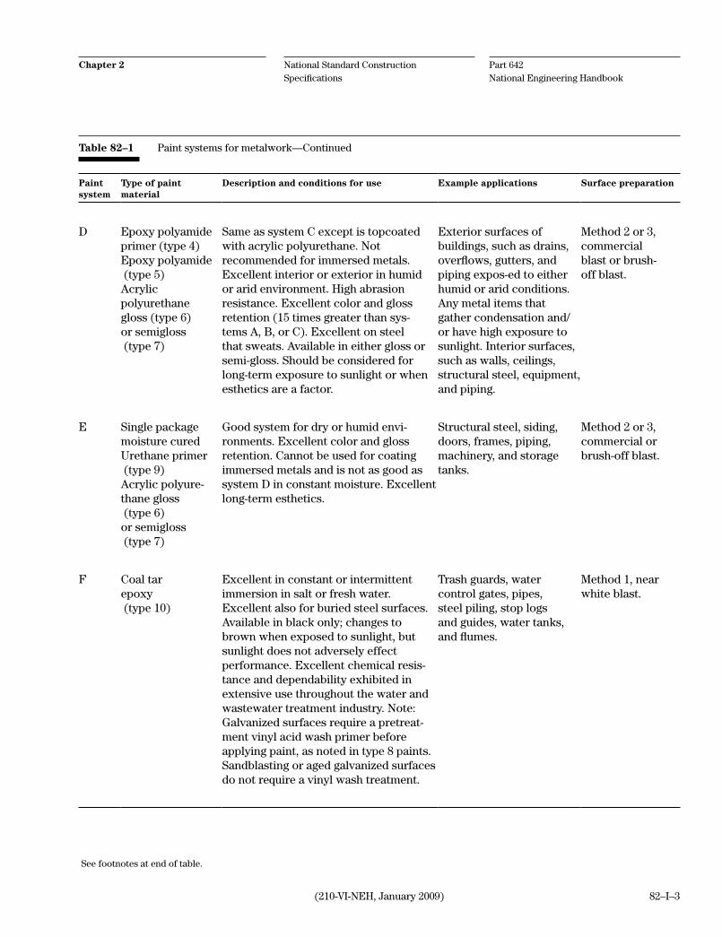
Part 642 National Engineering Handbook
National Standard Construction Specifications
Chapter 2
(210-VI-NEH, January 2009) 82–I–3
Paintsystem
Type of paint material
Description and conditions for use Example applications Surface preparation
D Epoxy polyamideprimer (type 4)Epoxy polyamide (type 5)Acrylicpolyurethanegloss (type 6)or semigloss (type 7)
Same as system C except is topcoatedwith acrylic polyurethane. Not recommended for immersed metals.Excellent interior or exterior in humid or arid environment. High abrasionresistance. Excellent color and glossretention (15 times greater than sys-tems A, B, or C). Excellent on steel that sweats. Available in either gloss or semi-gloss. Should be considered for long-term exposure to sunlight or when esthetics are a factor.
Exterior surfaces ofbuildings, such as drains, overflows, gutters, and piping expos-ed to either humid or arid conditions. Any metal items that gather condensation and/or have high exposure to sunlight. Interior surfaces, such as walls, ceilings, structural steel, equipment, and piping.
Method 2 or 3,commercial blast or brush-off blast.
E Single packagemoisture curedUrethane primer (type 9)Acrylic polyure-thane gloss (type 6)or semigloss (type 7)
Good system for dry or humid envi-ronments. Excellent color and gloss retention. Cannot be used for coating immersed metals and is not as good as system D in constant moisture. Excellent long-term esthetics.
Structural steel, siding,doors, frames, piping,machinery, and storage tanks.
Method 2 or 3,commercial orbrush-off blast.
F Coal tarepoxy (type 10)
Excellent in constant or intermittentimmersion in salt or fresh water.Excellent also for buried steel surfaces.Available in black only; changes to brown when exposed to sunlight, butsunlight does not adversely effectperformance. Excellent chemical resis-tance and dependability exhibited in extensive use throughout the water and wastewater treatment industry. Note: Galvanized surfaces require a pretreat-ment vinyl acid wash primer before applying paint, as noted in type 8 paints. Sandblasting or aged galvanized surfaces do not require a vinyl wash treatment.
Trash guards, watercontrol gates, pipes, steel piling, stop logs and guides, water tanks, and flumes.
Method 1, near white blast.
Table 82–1 Paint systems for metalwork—Continued
See footnotes at end of table.

Part 642 National Engineering Handbook
National Standard Construction Specifications
Chapter 2
(210-VI-NEH, January 2009)82–I–4
Paintsystem
Type of paint material
Description and conditions for use Example applications Surface preparation
G
Epoxy polyamideprimer (type 4)Single packagemoisture curedurethane (type 9)
Excellent system for repair of damagedgalvanized metal in humid or aridenvironments. Provides protectionfor surfaces exposed to constant humidity and sweating.
Trash guards, CMP, stop logs and guides,and other galvanizedmetalwork.
Method 4 or 5,hand tool orsolvent clean.
H Vinyl acidwash treatment (type 8)
For use as a pretreatment wash forgalvanized and nonferrous metals that require painting.
Trash guards, CMP,stop logs and guides,gutters, downspouts, and other galvanizedor nonferrous metals.
Steam clean with TSP, or solvent clean, regularly chang-ing rags.
Footnotes:a. All surface preparation referred to herein shall be performed in accordance with SSPC (Steel Structures Painting Council).b. All painting and coating shall be performed per SSPC Good Painting Practices and paint manufacturer's recommendations.c. Coated steel subjected to potable water service shall be coated in accordance with American Water Works Association (AWWA) provisions
and directions. Said coatings shall meet United States National Sanitation Foundation (US-NSF) requirements.d. When special protective coatings or other specific painting recommendations are necessary, refer to the Paint Manual, United States Depart-
ment of Interior (USDI), Bureau of Reclamation, or paint manufacturer's data.e. Surface preparation indicated is the method that will provide coating quality appropriate for exposure conditions. Methods that produce a
greater or a lesser quality can be chosen to produce the quality of work that is necessary. Hand tool cleaning (method 4) and solvent clean-ing (method 5) are applicable for field applications, small areas requiring coating, or in making repairs to factory coatings.
Table 82–1 Paint systems for metalwork—Continued

82–1(210–VI–NEH, November 2005)
1. ScopeThe work consists of cleaning metal surfaces and applying paints and protective coatings.
2. PaintFor the purpose of this specification, paints and coatings shall be designated by types as defined below.
Materials for systems requiring two or more coats shall be supplied by the same manufacturer.
Unless otherwise specified and before application, the contractor shall furnish in writing to the engineer for ap-proval a plan outlining procedures proposed for painting metalwork and a list of material including name of manufacturer, pertinent product identification names and numbers, and product data sheets. Data shall reflect the requirements set forth in this section.
Type 1—Alkyd primer. Alkyd based, rust inhibitive primer shall be lead and chromate free. Primer shall have a minimum of 54 percent solids, by volume. Color availability shall be red, gray, and white. Primer shall be able to be applied satisfactory at 2 to 3 mils dry-film thickness in one coat.
Type 2—Alkyd enamel (gloss). Alkyd based enamel shall be lead free. It shall have a minimum of 49 percent solids, by volume. Alkyd enamel shall be able to be applied satisfactory at 2 to 3 mils dry-film thickness in one coat. Finish shall be gloss.
Type 3—Alkyd enamel (semigloss). Alkyd based enamel shall be lead free. It shall have a minimum of 55 per-cent solids, by volume. Alkyd enamel shall be able to be applied satisfactory at 2 to 3 mils dry-film thickness in one coat. Finish shall be semigloss.
Type 4—Epoxy polyamide primer. Epoxy polyamide primer shall be lead and chromate free. It shall have a minimum of 56 percent solids, by volume. Epoxy primer shall be able to be applied satisfactory at 4 to 6 mils dry-film thickness in one coat. Color availability shall be red, gray, and white. Epoxy primer shall conform to AWWA Standard C 210 and AWWA Standard D 102.
Type 5—Epoxy polyamide (intermediate or finish). Epoxy polyamide shall be lead free. It shall have a mini-mum of 56 percent solids, by volume. Epoxy polyamide shall be able to be applied satisfactory at 4 to 6 mils dry-film thickness in one coat. Finish shall be semigloss. Epoxy finish shall conform to AWWA C 210 and AWWA D 102.
Type 6—Acrylic polyurethane (gloss). Acrylic polyurethane shall be lead free. It shall have a minimum of 74 percent solids, by volume. Polyurethane shall be able to be applied satisfactory at 3 to 5 mils dry-film thickness in one coat. Finish shall be gloss.
Type 7—Acrylic polyurethane (semigloss). Acrylic polyurethane shall be lead free. It shall have a minimum of 58 percent solids, by volume. Polyurethane shall be able to be applied satisfactory at 3 to 5 mils dry-film thickness in one coat. Finish shall be semigloss.
Type 8—Vinyl acid wash treatment. Pretreatment primer for galvanized and nonferrous metal. Pretreatment primer shall have a minimum of 8 percent solids, by volume. The applied dry-film thickness of pretreatment primer shall not exceed 0.5 mil. Steel primed with pretreatment primer shall be topcoated within 6 to 8 hours in humid conditions.
Construction Specification 82—Painting Metalwork

82–2 (210–VI–NEH, November 2005)
Type 9—Single package moisture cured urethane primer. Urethane primer shall have a minimum of 50 per-cent solids, by volume. Primer shall be able to be applied satisfactory at 2 to 3 mils dry-film thickness in one coat. Color shall be metallic aluminum.
Type 10—Coal tar epoxy. Coal tar epoxy shall have a minimum of 75 percent solids, by volume, and conform to the requirements of NRCS Material Specification 583 Coal Tar Epoxy Paint (Steel Structures Paint Council PS No. 16, Type I). Coal tar epoxy shall be able to be applied satisfactory at 8 to 15 mils dry-film thickness in one coat.
3. TintingTinting shall not be performed in the field unless otherwise specified.
4. Surface preparationSurfaces to be painted shall be thoroughly cleaned before the application of paint or coatings. Surface preparations required by this specification are as designated by SSPC (Steel Structures Painting Council) and are summarized by the methods listed in this section.
Method 1—Near white blast (SSPC-SP10). All surfaces to be coated shall be prepared by removing all grease and oil using steam cleaning or solvent cleaning methods per method 5. After degreasing is completed, sand or grit blasting shall be performed to remove all dirt, rust, mill scale, and other foreign material or residue. The cleaned, finished surface shall be a minimum of 95 percent free of all visible foreign material or residue.
Method 2—Commercial blast (SSPC-SP6). All surfaces to be coated shall be prepared by removing all grease and oil using steam cleaning or solvent cleaning methods per method 5. After degreasing is completed, sand or grit blasting shall be performed to remove all dirt, rust, mill scale, or other foreign material or residue. The cleaned, finished surface shall be a minimum of 67 percent free of all visible foreign material or residue.
Method 3—Brush-off blast cleaning (SSPC-SP7). All surfaces to be coated shall be prepared by removing all grease and oil using steam cleaning or solvent cleaning methods per method 5. After degreasing is completed, sand or grit blasting shall be performed to remove dirt, rust, mill scale, or other foreign material or residue. Mill scale, rust, and paint are considered tightly adherent if they cannot be removed by lifting with a dull putty knife.
Method 4—Hand tool cleaning (SSPC-SP2). All surfaces to be coated shall be prepared by removing all oil or grease using steam cleaning or solvent cleaning methods per method 5. After degreasing is completed, nonpower handtools shall be used to remove loose, detrimental foreign material. Adherent mill scale, rust, and paint need not be removed.
Method 5—Solvent cleaning (SSPC-SP1). Surfaces to be coated shall be prepared by removing all visible oil, grease, soil, drawing and cutting compounds, and other soluble contaminants from surfaces with solvents or com-mercial cleaners using various methods of cleaning, such as wiping, dipping, steam cleaning, or vapor degreasing.
5. Paint systemsFor the purposes of this specification, systems of painting and coating metalwork are designated as defined in this section.
Paint system A—Consists of the application of one primer coat of type 1 and two or more coats of type 2 (gloss) or type 3 (semigloss) to provide a minimum dry-film thickness of 6 mils.

82–3(210–VI–NEH, November 2005)
Paint system B—Consists of the application of one primer coat of type 9 and two or more coats of type 2 (gloss) or type 3 (semigloss) to provide a minimum dry-film thickness of 6 mils.
Paint system C—Consists of the application of one coat of type 4 and one or more coats of type 5 to provide a minimum dry-film thickness of 8 mils.
Paint system D—Consists of the application of one coat of type 4 primer, one coat of type 5, and one coat of type 6 (gloss) or type 7 (semigloss) to provide a minimum dry-film thickness of 11 mils.
Paint system E—Consists of the application of one coat of type 9 and one coat of type 6 (gloss) or type 7 (semi-gloss) to provide a minimum dry-film thickness of 5 mils.
Paint system F—Consists of the application of two coats of type 10 at a dry-film thickness of 8 mils. per coat. Total system shall provide a minimum dry-film thickness of 16 mils.
Paint system G—Consists of the application of two coats of type 4 and two coats of type 9 paint. Total system shall provide a minimum dry-film thickness of 14 mils.
6. Application of paintSurfaces shall be painted immediately after preparation or within the same day as prepared with a minimum of one coat of the primer type specified. Remaining surfaces not required to be painted shall be protected against contami-nation and damage during the cleaning and painting operation.
Paints shall be thoroughly mixed immediately before application.
After erection or installation of the metalwork, all damage to shop-applied coating shall be repaired and all bolts, nuts, welds, and field rivet heads shall be cleaned and painted with one coat of the specified priming paint.
Initial priming coats shall be applied by brush except on surfaces accessible only to spray equipment. All other coats may be applied by brush or spray. Each coat shall be applied in such a manner to produce a paint film of uniform thickness with a rate of coverage within the guidelines and limits recommended by the paint manufacturer and as outlined in section 2 of this specification.
The drying time between coats shall be as prescribed by the paint manufacturer, but not less than that required for the paint film to thoroughly dry. The elapsed time between coats in paint system F shall not exceed 24 hours. If for any reason the critical recoat time is exceeded, the coated surface shall be treated with the manufacturer's recom-mended tackifier solvent or brush blasted to roughen the surface.
The finished surface of each coat shall be free from runs, drops, ridges, laps, or excessive brushmarks and shall present no variation in color, texture, and finish. The surface of each dried coat shall be cleaned as necessary be-fore application of the next coat.
7. Atmospheric conditionsPaint application shall not be performed when the temperature of the item to be painted or the surrounding air is less than 50 degrees Fahrenheit. Painting shall be performed only when the humidity and temperature of the sur-rounding air and the temperature of the metal surfaces are such that evaporation rather than condensation results during the time required for application and drying. The surface shall be dry and a minimum of 5 degrees Fahren-heit above the dew point. Surfaces protected from adverse atmospheric conditions by special cover, heating, or ventilation shall remain so protected until the paint is thoroughly dry.

82–4 (210–VI–NEH, November 2005)
8. TestsDry-film thickness on ferrous metal shall be determined by the use of a nondestructive magnetic instrument, such as an Elcometer or Mikrotest gauge. Instruments shall have been calibrated within 1 month before use. Film thick-ness on nonferrous metal shall be determined with film gauges during the application process. Systems with film thickness less than specified shall be brought into conformance by the application of one or more additional coats of the specified material.
9. PaymentFor items of work for which lump sum prices are established in the contract, payment is made as the work pro-ceeds, but after presentation of invoices by the contractor supporting actual related costs and evidence of the charges of suppliers, subcontractors, and others for supplies furnished and work completed. If the total of such payments is less than the lump sum contract price for this item, the unpaid balance is included in the next appro-priate contract payment. Payment of the lump sum contract price constitutes full compensation for completion of the work.
Compensation for any item of work described in the contract, but not listed in the bid schedule, is included in the payment for the item of work to which it is made subsidiary. Such items and the items to which they are made sub-sidiary are identified in section 10 of this specification.
10. Items of work and construction details
Part 642 National Engineering Handbook
National Standard Construction Specifications
Chapter 2
(210-VI-NEH, January 2009) 83–I–1
1. ApplicabilityConstruction Specification 83 is applicable to all types of timber construction (except pile driving or the use of round timber) that are normally an integral part of struc-tures designed and installed under agency programs. Supplementary specifications will be required for works of a special nature, such as bridges or buildings.
2. Material specificationsMaterial Specifications 581, 582, 584, and 585 and Con-struction Specification 84 complement Construction Specification 83.
3. Included itemsItems to be included in contract specifications and drawings follow:
a. Plans and dimensions of all structural ele-ments.
b. Complete details of all connections including number, type, size, and kind of nails or spikes or bolts with nuts if the design requires that these be specified; depth of embedment of screws and pins, and other such information.
c. For lumber and timber, specify:
(1) Stress grade
(2) Species according to standard commercial name
(3) Heartwood requirements or other special requirements
(4) Nominal size and dress requirements (rough or dressed)
(5) For preservative treated wood, specify the type of preservative and the use category. For guidance in determining the applicable use category, refer to the American Wood-Preservers' Association Standard U1 at http://www.awpa.com. Preservatives may be creosote, water-born preservatives, or oil-born preservatives. With respect to where they may be used, water-born pre-
Instructions for use
Construction Specification 83—Timber Fabrication and Installation
servatives are generally less restricted than creosote and oil-born preservatives. Thus, water-born preservatives are generally pre-ferred over creosote and oil-born preserva-tives. Common water-born preservatives are: acid copper chromate (ACC); ammo-niacal copper zinc arsenate (ACZA); chro-mated copper arsenate (CCA); alkyl am-monium compound (AAC); alkaline copper quaternary (ACQ); copper azole (CA); and copper naphthenate, waterborne (CuN-W). Common oil-born preservatives are pen-tachlorophenol (penta) and copper naph-thenate (CuN). All types of preservatives should be restricted from contact with feed for animal consumption and food and water for human consumption. Some preservatives such as creosote and penta should also be restricted from contact with skin (human or animal) and animal drink-ing water. Refer to the applicable material safety data sheet (MSDS) for information on preservative restrictions.
(6) Applicable grading rule, including the name of the agency that sponsors the rule (such as National Hardwood Lumber As-sociation), the paragraph number, and year of issue.
d. For plywood and chipboard, specify:
(1) Number of plies, width and length of sheet
(2) Species or group according to PS 1
(3) Grade
(4) Type (exterior, interior)
(5) Finished thickness
(6) Finish requirements (such as sanded or unsanded)
e. Designation of surfaces to be painted.
f. Special instructions concerning cutting of treated lumber or timber, if such operations are to be allowed.
Part 642 National Engineering Handbook
National Standard Construction Specifications
Chapter 2
(210-VI-NEH, January 2009)83–I–2
g. Any deviation from the requirement in Mate-rial Specification 585 to use stainless steel for all fasteners, connectors, and any other metal contacting alkali copper quaternary (ACQ) or copper azole (CA) treated wood.
4. MethodsSection 6, Measurement and payment
Method 1—Intended for use in cases where the quan-tities of lumber and timber are large and the measure-ment of structural elements is feasible.
Method 2—Considered more appropriate for struc-tures of moderate size.
Method 3—Provides a flexible method of payment when there are some structure units that can be paid for as completed structures and also structures that lend themselves to partial payment on a linear foot basis.
When specifications are prepared using electronic procedures and all methods but one are deleted for use in a contract specification, delete from the last paragraph, All Methods—The following provisions apply to all methods of measurement and pay-ment. Left justify the remaining text.
5. Items of work and construction detailsStarting at the top of page 83–2, prepare and outline job specific "Items of Work and Construction Details" (IWCD) in accordance with these instructions.

83–1(210–VI–NEH, January 2009)
1. ScopeThe work shall consist of the construction of timber structures and timber parts of composite structures.
2. MaterialStructural timber and lumber shall conform to the requirements of Material Specification 584. Treated timber and lumber shall be impregnated with the specified type and quantity of preservative and in the manner specified in Material Specification 585.
Hardware, except cast iron, shall be galvanized as specified for iron and steel hardware in Material Specification 582. Unless otherwise specified, structural steel shapes, plates, and rods shall not be galvanized. Nuts, driftbolts, dowels, and screws shall be either wrought iron or steel.
Steel bolts shall conform to the requirements of ASTM A 307. When galvanized or zinc-coated bolts are specified, the zinc coating shall conform to the requirements of Material Specification 582.
Washers shall be ogee gray iron castings or malleable iron castings unless washers cut from medium steel or wrought iron plate are specified on the drawings or in section 7 of this specification. Cast washers shall have a thickness equal to the diameter of the bolt and a diameter equal to four times the thickness. The thickness for plate washers shall be equal to half the diameter of the bolt, and the sides of the square shall be equal to four times the diameter of the bolt. Holes in washers shall have a maximum diameter of 1/8 inch larger than the diameter of the bolt. Split ring connectors, tooth ring connectors, and pressed steel shear plate connectors shall be manufactured from hot-rolled, low carbon steel conforming to the requirements of ASTM A 711, Grade 1015. Malleable iron shear plate connectors and spike grid connectors shall be manufactured in conformance with the requirements of ASTM A 47, Grade No. 35018. All connectors shall be of approved design and the type and size specified.
Structural shapes, rods, and plates shall be structural steel conforming to the requirements of Material Specifica-tion 581. No welds are permitted in truss rods or other main members of trusses or girders.
3. WorkmanshipAll framing shall be true and exact. Timber and lumber shall be accurately cut and assembled to a close fit and shall have even bearing over the entire contact surface. No open or shimmed joints will be accepted. Nails and spikes shall be driven with just sufficient force to set the heads flush with the surface of the wood. Deep hammer marks in wood surfaces shall be considered evidence of poor workmanship and may be sufficient cause for rejection of the work.
Holes for round driftpins and dowels shall be bored with a bit 1/16 inch smaller in diameter than that of the drift-pin or dowel to be installed. The diameter of holes for square driftpins or dowels shall be equal to one side of the driftpin or dowel. Holes for lag screws shall be bored with a bit not larger than the body of the screw at the base of the thread.
Washers shall be used in contact with all bolt heads and nuts that would otherwise be in contact with wood. Cast iron washers shall be used when the bolt will be in contact with earth. All nuts shall be checked or burred effec-tively with a pointed tool after finally tightened.
Unless otherwise specified, surfacing, cutting, and boring of timber and lumber shall be completed before treat-ment. If field cutting or field repair of treated timber and lumber is approved, all cuts and abrasions shall be care-
Construction Specification 83—Timber Fabrication and Installation
83–2 (210–VI–NEH, January 2009)
fully trimmed and coated with copper naphthenate preservative containing a minimum of 2.0 percent copper metal. The treatment preservative shall be applied according to the product label. Any excess preservative not absorbed by the wood member shall be cleaned from the surface prior to the use of the member. Bored holes for connectors or bolts may be treated by pumping coal-tar roofing cement meeting ASTM D5643 into the holes using a caulking gun or similar device. After timber assembly, any unfilled holes shall be plugged with tightly fitting wooden plugs that have been treated with preservative as specified.
4. Handling and storing materialAll timber and lumber stored at the site of the work shall be neatly stacked on supports a minimum of 12 inches above the ground surface and protected from the weather by suitable covering(s). Untreated material shall be staked and stripped to permit free circulation of air between the tiers and courses. Treated timber may be close-staked. The ground surface for the stockpile of timber and lumber shall be free of weeds and rubbish. The use of cant hooks, peavies, or other pointed tools except end hooks is not permitted in the handling of structural timber and/or lumber. Treated timber shall be handled with rope slings or by other methods that prevent the breaking or bruising of outer fibers or penetration of the surface in any manner.
5. PaintingExcept as otherwise specified, surfaces designated for painting shall be prepared and painted in accordance with Construction Specification 84.
6. Measurement and paymentMethod 1—The unit of measurement of lumber and timber is the number of thousand feet board measure (MBM) of each type, size, species, and grade of lumber and timber installed in the completed structure. The quantity of each type, size, species, and grade is computed from the nominal dimensions and actual lengths of the pieces in the completed structure and does not include waste timber used for erection purposes (such as falsework or tempo-rary sheeting and bracing) or any part of any pile or other round timber. The total quantity of lumber and timber in each type, size, species, and grade is computed to the nearest 0.01 MBM.
The unit of measurement of plywood is the number of square feet of each type, species, grade, and thickness in-stalled in the completed structure.
Payment for each type, size, species, and grade of lumber and timber is made at the contract unit price for that type, size, species, and grade. Payment for each type, species, grade, and thickness of plywood is made at the contract unit price for that type, species, grade, and thickness. Such payment is considered full compensation for completion of the work.
Method 2—No measurement of material quantities is made. Payment for each structure, complete in place, is made at the contract lump sum price for that structure. Such payment is considered full compensation for comple-tion of the work.
Method 3—For items of work for which specific unit prices are established in the contract, measurement and pay-ment for each structure unit except those for which a linear foot payment is established is counted and payment made at the contract unit price. Items for which a linear foot payment is established are measured to the nearest linear foot, and payment is made at the contract unit prices as appropriate. Such payment is considered full com-pensation for completion of the work.
All methods—The following provisions apply to all methods of measurement and payment. Compensation for any item of work described in the contract, but not listed in the bid schedule, is included in the payment for the item of work to which it is made subsidiary. Such items and the items to which they are made subsidiary are identified in section 7 of this specification.
7. Items of work and construction details

Part 642 National Engineering Handbook
National Standard Construction Specifications
Chapter 2
(210-VI-NEH, January 2009) 84–I–1
Instructions for use
Construction Specification 84—Painting Wood
1. ApplicabilityConstruction Specification 84 is applicable to the exte-rior painting of wood material.
2. Material specificationsNo material specifications complement Construction Specification 84.
3. Included itemsItems to be included in construction specifications and drawings follow:
a. Surfaces to be painted.
b. Instructions for tinting if colors other than white are required.
c. Paint and primer to be used if other than speci-fied in section 2.
d. Number of paint and/or primer coats if other than specified in section 4.
4. MethodsNo methods are included.
5. Items of work and construction detailsStarting at the top of page 84–2, prepare and outline job specific "Items of Work and Construction Details" (IWCD) in accordance with these instructions.

Part 642 National Engineering Handbook
National Standard Construction Specifications
Chapter 2
(210-VI-NEH, January 2009)84–I–2

84–1(210–VI–NEH, November 2005)
Construction Specification 84—Painting Wood
1. ScopeThe work shall consist of cleaning and preparing wood surfaces and applying protective paint coatings.
2. MaterialUnless otherwise specified in section 7 of this specification, painting material shall meet the following require-ments:
• ExteriorpaintprimershallconformtotherequirementsofMasterPaintersInstitute—MPI#5ExteriorAl-kyd Wood Primer.
• ExterioroilpaintshallconformtotherequirementsofMasterPaintersInstitute—MPI#8ExteriorAlkyd,Flat. Unless otherwise specified, the color shall be white. The second coat of exterior oil paint may be thinned with mineral spirits conforming to the requirements of ASTM D 235 or with pure gum turpentine. The amount of thinner shall not exceed 1 pint per gallon of paint.
• Whentintingisrequired,itshallbeaccomplishedbytheadditionofpigment-in-oiltintingcolorsconformingto the requirements of Federal Specification A-A-3108A.
3. Surface preparationAll surfaces to be painted/primed shall be thoroughly cleaned before the application of paint/primer. Pitch pockets and knots shall be scraped and sealed with a shellac varnish conforming to the requirements of ASTM D 360. Previ-ously painted surfaces shall be scraped and brushed to remove any checked or blistered paint and all excess chalk.
4. Application of paint/primerSurfaces shall be clean and dry during paint/primer application. No paint/primer shall be applied until the prepared surfaces have been inspected and approved for paint/primer application.
Surfaces of new wood shall be painted with 1 brush coat of exterior primer paint and two brush coats of exterior oil paint unless otherwise specified in section 7 of this specification.
Paints/primers shall be thoroughly mixed at the time of application.
Each paint and primer coat shall be applied in such a manner as to produce a coating film of uniform thickness with a finished surface free of runs, drops, ridges, laps, or excessive brush marks. The minimum drying time be-tween applications shall be as prescribed by the manufacturer of the paint/primer and not before the previous paint/primer application being thoroughly dry.
The surface of each dried coating shall be cleaned as necessary before application of the next coat.
The first coat of exterior oil paint shall be tinted off-color by the addition of 3 ounces of an appropriate tinting color per gallon of paint.
5. Atmospheric conditionsUnless otherwise specified in section 7 of this specification or by the manufacturer of the coating products, paint and primer shall not be applied when the temperature of the wood surface or of the surrounding air is less than 45 degrees Fahrenheit. Coatings shall not be applied when atmospheric conditions result in moisture condensation on the surface to be painted/primed. Surfaces protected from atmospheric conditions by special cover or enclosure, heating, or ventilation shall remain to provide full protection until the paint/primer is thoroughly dry.

84–2 (210–VI–NEH, November 2005)
6. PaymentFor items of work for which specific lump sum prices are established in the contract, payment for priming and painting wood is made at the contract lump sum price. Such payment is full compensation for furnishing, prepar-ing the surfaces, and applying all coating material to wood surfaces designated to be painted including labor, tools, equipment, material, and all other items necessary and incidental to the completion of the work.
Compensation for any item of work described in the contract, but not listed in the bid schedule is included in the payment for the item of work to which it is made subsidiary. Such items and the item to which they are made sub-sidiary are identified in section 7 of this specification.
7. Items of work and construction details

Part 642 National Engineering Handbook
National Standard Construction Specifications
Chapter 2
(210-VI-NEH, January 2009) 91–I–1
1. ApplicabilityConstruction Specification 91 is applicable to the installation of chain link fences.
2. Material specificationsNo material specifications complement Construction Specification 91.
3. Included itemsItems to be included in contract specifications and drawings follow:
a. Plan showing the location and extent of fences including location of gates, corners, pull posts, and end points.
b. Dimensions of the fence including post spacing, clearance from ground, and height of fence.
c. Details of posts and assemblies:
(1) Types of post and top rails if other than specified in section 2.
(2) Line post detail showing height of post, depth of embedment.
(3) Details of corner post assembly, pull post, and corner post, including embedment, top rail connections, tension wire detail, braces, and trusses.
(4) Show diameters of embedment items.
(5) Special anchor requirements, if any.
d. Dimensions of gate opening (clear opening between inside faces of the gateposts).
e. Dimensions of gates and type if other than specified in section 2.
f. Required appurtenances, such as locks with number of keys, barbed wire arms, barbed wire, and post tops.
g. Type, mesh, and gauge of chain link fabric, if other than specified in section 2.
h. If the fence material is to be PVC coated, the following information should be included in the Items of Work and Construction Details:
(1) Specify PVC coating for the fence material.
(2) Specify desired standard color of PVC coating (see ASTM F 934) if other than black is to be used.
4. MethodsSection 5, Measurement and payment
Method 1—Intended for use when gates are a minor part of the work item.
Method 2—Intended for use when gates form a sub-stantial part of the work item or when gates must be installed in existing fences.
When specifications are prepared using electronic pro-cedures and all methods but one are deleted for use in a contract specification, delete from the last paragraph All Methods—The following provisions apply to all methods of measurement and payment. Left justify the remaining text.
5. Items of work and construction detailsStarting at the top of page 91–2, prepare and outline job specific "Items of Work and Construction Details" (IWCD) in accordance with these instructions.
Instructions for use
Construction Specification 91—Chain Link Fence

Part 642 National Engineering Handbook
National Standard Construction Specifications
Chapter 2
(210-VI-NEH, January 2009)91–I–2

91–1(210–VI–NEH, May 2001)
1. ScopeThe work consists of furnishing and installing chain link fencing complete with all posts, braces, gates, and all other appurtenances.
2. MaterialThe material for the chain link fence shall be as follows:
GalvanizedChain link fence fabric shall conform to the requirements of ASTM A 392, 2-inch mesh and 9-gauge galvanized steel wire. Zinc coating shall be class 2.
Posts and fence framework shall conform to the requirements of ASTM F 1043 Group 1A, for Heavy Industrial Fence. Coatings shall be a type A galvanized coating for internal and external surfaces. Steel pipe posts shall con-form to the requirements of ASTM F 1043 and F 1083.
Fence fittings shall conform to the requirements of ASTM F 626. Fittings shall be galvanized steel. Wire ties and clips shall be 9-gauge.
Gates, gateposts, and gate accessories shall conform to the requirements of ASTM F 900. Coating shall be the same as selected for adjoining fence and framework.
Barbed wire shall be 12.5 gauge and shall conform to the requirements of ASTM A 121, chain link fence grade.
Galvanized and PVC coatedChain link fence fabric shall conform to the requirements of ASTM F 668 for class 2a or 2b, 2-inch mesh, and 9-gauge galvanized steel wire. The fabric shall have a polymer top coating of the color specified in section 6.
Posts and fence framework shall conform to the requirements of ASTM F 1043 Group 1A, for Heavy Industrial Fence. Coatings shall be a type A galvanized coating for internal and external surfaces and covered with a polymer top coating of color as specified in section 6.
Fence fittings shall conform to the requirements of ASTM F 626. Fittings shall be galvanized steel with a polymer top coating of color as specified in section 6.
Any damage to the coating shall be repaired in accordance with the manufacturer's recommendations, or the dam-aged fencing material shall be replaced. The contractor shall provide the engineer a copy of the manufacturer's recommended repair procedure and materials before correcting damaged coatings.
3. Installing fence postsUnless otherwise specified, line posts shall be placed at intervals of 10 feet measured from center to center of adja-cent posts. In determining the post spacing, measurement is made parallel with the ground surface.
Posts shall be set in concrete backfill in the manner shown on the drawings.
Posts set in the tops of concrete walls shall be grouted into preformed holes to a depth of 12 inches.
Construction Specification 91—Chain Link Fence

91–2 (210–VI–NEH, May 2001)
All corner posts, end posts, gateposts, and pull posts shall be embedded, braced, and trussed as shown on the drawings or in accordance with appropriate industry practice if not otherwise shown or specified.
4. Installing wire fabricFencing fabric shall not be stretched until at least 4 days after the posts are grouted into walls or 7 days after the posts are set in the concrete backfill.
Fencing fabric shall be installed on the side of the posts designated on the drawings.
The fabric shall be stretched taut and securely fastened, by means of tie clips, to the posts at intervals not exceed-ing 15 inches and to the top rails or tension wires at intervals not exceeding 2 feet. Care shall be taken to equalize the fabric tension on each side of each post.
Barbed wire shall be installed as shown on the drawings and shall be pulled taut and fastened to each post or arm with the tie wires or metal tie clips.
5. Measurement and paymentMethod 1—The length of fence is measured to the nearest 0.1 foot along the fence, including gates. Payment is made at the contract unit price for the specified height of fence. Such payment constitutes full compensation for all labor, material, equipment, and all other items necessary and incidental to the completion of the work.
Method 2—The length of fence is measured to the nearest 0.1 foot along the fence, excluding gate openings. Pay-ment is made at the contract unit price for the specified height of fence. The number of each size and type of gate installed is determined. Payment is made at the contract unit price for that type and size of gate. Such payment constitutes full compensation for all labor, material, equipment, and all other items necessary and incidental to the completion of the work.
All methods—The following provisions apply to all methods of measurement and payment. Compensation for any item of work described in the contract, but not listed in the bid schedule, is included in the payment for the item of work to which it is made subsidiary. Such items and the items to which they are made subsidiary are identified in section 6 of this specification.
6. Items of work and construction details

Part 642 National Engineering Handbook
National Standard Construction Specifications
Chapter 2
(210-VI-NEH, January 2009) 92–I–1
1. ApplicabilityConstruction Specification 92 is applicable to the installation of field fence of the barbed wire, woven wire, or wire netting types.
2. Material specificationsMaterial Specification 591 complements Construction Specification 92.
3. Included itemsItems to be included in contact specifications and drawings follow:
a. Plan showing the location and extent of fences including location of gates, corners, braces, and end points.
b. Dimensions of the fence including post spacing, clearance from ground and height of fence.
c. Details of concrete or other specialty post, if required.
d. Details of posts and assemblies.
(1) Type and kind of posts as defined and ref-erenced in Material Specification 591.
(2) Line post detail showing height of post, depth of embedment.
(3) Details of end panel assembly, pull post as-sembly, brace panel assembly, and corner assembly including types of posts, types of backfill, types and dimensions of braces, gauges of tension wires and details of fas-tening of tension wires to post.
(4) Special anchor requirements for posts at crossings over depressions or waterways.
(5) Where fencing is to be placed on a curved alignment, special consideration should be given to providing adequate vertical stabil-ity for prevention of pullover. Consider-ation should include spacing of end panels, post spacing, type of posts, and post depth.
e. Details of gates listed in this section may often be shown on a standard drawing developed for use for fencing projects within an agency administrative area.
f. Type and kind of fencing as defined in section 11.
(1) For barbed wire fencing, specify the type, gauge of wire, gauge and spacing of barbs, and the number of points per barb.
(2) For woven wire fencing, specify the type, style, design number, and tensile strength grade.
(3) For wire netting, specify the type, style, height of netting, size of mesh and gauge of wire, or design number and coating class.
(4) For high tensile strength wire fencing ma-terial, specify the strength grade classifica-tion.
g. Species of wood posts.
h. Preservative treatment of wood posts and braces, as applicable.
i. Protective coating (painted or zinc-coated) for steel posts and braces.
4. MethodsSection 10, Measurement and payment
Method 1—Intended for use when gates are simple and are considered to be of field fabricated type.
Method 2—Intended for use when gates must be shop fabricated, available on the market, or when gates must be installed within existing fences.
Instructions for use
Construction Specification 92—Field Fence

Part 642 National Engineering Handbook
National Standard Construction Specifications
Chapter 2
(210-VI-NEH, January 2009)92–I–2
When specifications are prepared using electronic pro-cedures and all methods but one are deleted for use in a contract specification, delete from the last paragraph All Methods—The following provisions apply to all methods of measurement and payment. Left justify the remaining text.
5. Items of work and construction detailsStarting at the top of page 92–2, prepare and outline job specific "Items of Work and Construction Details" (IWCD) in accordance with these instructions.

92–1(210–VI–NEH, January 2009)
1. ScopeThe work shall consist of furnishing and installing field fence, including gates and fittings.
2. MaterialMaterial for field fence shall conform to the requirements of Material Specification 591. All wooden posts shall be of the same species, when available.
Unless otherwise specified, surfacing, cutting, and boring of preservative treated wooden posts and braces shall be completed before treatment. If field cutting or field repair of treated material is approved, all cuts and abrasions shall be carefully trimmed and coated with copper naphthenate preservative containing a minimum of 2.0 percent copper metal. The treatment preservative shall be applied according to the product label. Any excess preservative not absorbed by the wood member shall be cleaned from the surface prior to the use of the member. Bored holes for connectors or bolts may be treated by pumping coal-tar roofing cement meeting ASTM D5643 into the holes using a caulk gun or similar device. After assembly, any unfilled holes shall be plugged with tightly fitting wooden plugs that have been treated with preservative as specified.
3. Setting postsConcrete or wood posts shall be set in holes and backfilled with earth except where otherwise specified. Wood posts may be driven when approved by the engineer. Steel posts shall be driven unless otherwise specified.
Holes for installing fence posts shall be at least 6 inches larger than the diameter or side dimension of the posts.
Earth backfill around posts shall be thoroughly tamped in layers not thicker than 4 inches and shall completely fill the posthole up to the ground surface. Concrete backfill around posts shall be rodded into place in layers not thicker than 12 inches and shall completely fill the posthole to the surface of the ground. Backfill, either earth or concrete, shall be crowned-up around posts at the ground surface.
No stress shall be applied to posts set in concrete for a period of not less than 24 hours following the development of a firm set of the concrete.
4. Corner assemblyUnless otherwise specified in section 11, corner assemblies shall be installed at all points where the fence align-ment changes 15 degrees or more.
5. End panelsEnd panels shall be built at gates and fence ends.
6. Pull post assemblyPull post assembly (bracing within a section of straight fence) shall be installed at the following locations:
a. In straight fence sections, at intervals not to exceed 660 feet.
b. At any point where the vertical angle described by two adjacent reaches of wire is upward and exceeds 10 degrees (except as provided in section 11 of this specification).
c. At the beginning and end of each curved fence section.
Construction Specification 92—Field Fence

92–2 (210–VI–NEH, January 2009)
7. Attaching fencing to postsThe fencing shall be stretched and attached to posts as follows:
a. The fencing wire or netting shall be placed on the side of the post opposite the area being protected except for installation along curved sections.
b. The fencing wire or netting shall be placed on the outside for installation along curved sections.
c. The fencing wire or netting shall be fastened to each end post, corner post, and pull post by wrapping each horizontal strand around the post and tying it back on itself with not less than three tightly wound wraps.
d. The fencing wire or netting shall be fastened to wooden line posts by means of steel staples. Woven-wire fencing shall be attached at alternate horizontal strands. Each strand of barbed wire shall be attached to each post. Steel staples shall be driven diagonally with the grain of wood and at a slight downward angle and shall not be driven so tightly as to bind the wire against the post.
e. The fencing wire or netting shall be fastened to steel or concrete line posts with either two turns of 14 gauge galvanized steel or iron wire or in accordance with recommendations provided by the post's manufacturer.
f. Wire shall be spliced by means of a Western Union splice or by suitable splice sleeves applied with a tool designed for that purpose. The Western Union splice shall have no less than eight wraps of each end about the other. All wraps shall be tightly wound and closely spaced. Splices made with splice sleeves shall have a tensile strength no less than 80 percent of the strength of the wire being spliced.
8. StaysStays shall be attached to the fencing at the spacing outlined in section 11 or as shown on the drawings to ensure maintenance of the proper spacing of the fence wire strands.
9. Crossings at depressions and watercoursesWhere fencing is installed parallel to the ground surface, the line posts subject to upward pull shall be anchored.
a. If the fence wire or netting is installed parallel to the ground surface, the line posts subject to uplift shall be anchored by means of extra embedment or by special anchors as detailed on the drawings.
b. If the fence wire is installed with the top wire straight and parallel to the ground surface on either side of the depression, extra length posts shall be used to allow normal post embedment. Unless otherwise speci-fied, excess space between the bottom of the fence and the ground shall be closed with extra strands of barbed wire or with netting.
10. Measurement and paymentMethod 1—The length of each type and kind of fence is measured to the nearest foot along the profile of the fence, including gate openings. Payment for each type and kind of fence is made at the contract unit price for that type and kind of fence. Such payment constitutes full compensation for completion of the work, including fabricating and installing gates.
Method 2—The length of each type and kind of fence is measured to the nearest foot along the profile of the fence, excluding gate openings. Payment is made at the contract unit price for the specified height of fence. The number of each size and type of gate installed is determined. Payment is made at the contract unit price for that type and size of gate. Such payment constitutes full compensation for all labor, material, equipment, and all other items nec-essary and incidental to the completion of the work.
All methods—The following provisions apply to all methods of measurement and payment. Compensation for any item of work described in the contract, but not listed in the bid schedule, is included in the payment for the item of work to which it is made subsidiary. Such items and the items to which they are made subsidiary are identified in section 11 of this specification.
11. Items of work and construction details
Part 642 National Engineering Handbook
National Standard Construction Specifications
Chapter 2
(210-VI-NEH, January 2009) 93–I–1
1. ApplicabilityThe construction specification is applicable to the installation of identification markers or plaques to the works of improvement.
2. Material specificationsNo material specifications complement this specifi-cation. Any specific material requirements must be indicated in the specifications or on the drawings.
3. Included itemsItems to be included in contract specifications and drawings follows:
a. Complete detail drawings for each type, kind, and size of marker or plaque, including material requirements.
b. The style of letters and height of each line.
c. A carefully worded exhibit showing the exact arrangement of words.
d. The physical description for the installation location for each type and size of marker or plaque to be installed. Location selected should consider the audience intended and the poten-tial for vandalism.
e. Type of required monument or type of structure to which marker or plaque will be mounted.
f. For markers signifying buried structures, state and/or local government regulations for sign specifications may apply. Ensure that project sign message and state and/or local govern-ment rules do not conflict.
Instructions for use
Construction Specification 93—Identification Markers or Plaques4. MethodsSection 5, Measurement and Payment
Method 1—Intended for use when various sizes and types of markers or plaques are to be installed.
Method 2—Intended for use when a single marker or plaque is to be installed or multiple number of markers are to be installed and they are of similar type and size.
When specifications are prepared using electronic pro-cedures and all methods but one are deleted for use in a contract specification, delete from the last paragraph All Methods—The following provisions apply to all methods of measurement and payment. Left justify the remaining text.
5. Items of work and construction detailsStarting at the top of page 93–1, prepare and outline job specific "Items of Work and Construction Details" (IWCD) in accordance with these instructions.

Part 642 National Engineering Handbook
National Standard Construction Specifications
Chapter 2
(210-VI-NEH, January 2009)93–I–2

93–1(210–VI–NEH, May 2001)
1. Scope
The work consists of furnishing and installing identification markers or plaques at the designated locations.
2. MaterialThe markers or plaques shall be constructed of the specified material, and shall meet all requirements for lettering, painting, finishing, and related items as shown on the drawings or as specified in section 6 of this specification.
3. Construction methodsThe markers or plaques shall be installed at location(s) as shown on the drawings and in the manner or condition specified in section 6.
4. MonumentsUnless otherwise specified, the markers or plaques shall be mounted on concrete monuments, on existing struc-tures, or on structures proposed for installation under this contract.
5. Measurement and paymentMethod 1—For items of work for which specific unit prices are established in the contract, payment for each type, kind, and size of marker or plaque complete in place is made at the contract unit price for that type, kind, and size. Such payment constitutes full compensation for all labor, equipment, tools, and all other items necessary and inci-dental to the completion of the work.
Method 2—For items of work for which specific lump sum prices are established in the contract, payment for identification markers or plaques is made at the contract lump sum price. Such payment constitutes full compensa-tion for all labor, equipment, tools, and all other items necessary and incidental to the completion of the work.
All methods—The following provisions apply to all methods of measurement and payment. Compensation for any item of work described in the contract, but not listed in the bid schedule, is included in the payment for the item of work to which it is made subsidiary. Such items and the items to which they are made subsidiary are identified in section 6 of this specification.
6. Items of work and construction details
Construction Specification 93—Identification Markers or Plaques

Part 642 National Engineering Handbook
National Standard Construction Specifications
Chapter 2
(210-VI-NEH, May 2001)93–2

Part 642 National Engineering Handbook
National Standard Construction Specifications
Chapter 2
(210-VI-NEH, January 2009) 94–I–1
Instructions for useConstruction Specifications 94—Contractor Quality
1. ApplicabilityConstruction Specification 94 is applicable to con-tracts that require the contractor to provide quality control (QC), material testing, and verification of material quality before use.
2. Material specificationsNo material specifications complement Construction Specification 94. Any material requirements are to be specified in section 10 (see 3 b below).
3. Included itemsItems to be included in the contract specification and drawings follow:
a. Develop specific requirements for the quality control testing that the contractor is to pro-vide. Establish, as appropriate for the method selected, the types of material the contractor is required to test, types of representative tests required, frequency of tests, and other site spe-cific related details.
b. Provide details on the required intensity of contractor's quality control inspection efforts with emphasis on the site-specific aspects of the work, equipment, and material to be used. Specify, as appropriate for the method selected, the documentation required for verification of foundations and cutoff trench excavations, subgrade for fills, placement of reinforcement and forming before ordering concrete, equip-ment operational tests and available equipment backups, and safety measures specified. Pre-scribe specific requirements regarding:
(1) Reliance on contractor for initial or bench-mark testing, production testing, and testing to adjust to changes in material or methods.
(2) Standards to be used as reference for qual-ity control testing and field inspections of material, methods, and procedures.
(3) Special testing or inspection procedures that need to be included in the quality con-trol system.
c. Contract specific qualifications or requirements for professional registration or certification of QC personnel if necessary to meet Federal, State, or local statutes or job requirements.
d. Specify the required approvals by the contract-ing officer not covered in the basic specifica-tion for items, such as personnel qualifications, equipment condition, format of recordkeeping, and documentation.
e. Describe the cooperation and communication aspects for the quality control and quality as-surance activities.
4. MethodsSection 3, Quality Control System, and Section 4, Quality Control Personnel
Method 1—For use with the smaller or less complex work where the contractor's staff is expected to un-derstand and be qualified to perform routine quality control. The contractor must develop an effective quality control system. The contractor and contracting officer will meet and reach agreement on the system. Specify in section 10 if the contracting officer will document by correspondence to the contractor the understanding reached concerning the quality control system. When the project supervisor can also function as the contractor's quality control manager, so state in section 10.

Part 642 National Engineering Handbook
National Standard Construction Specifications
Chapter 2
(210-VI-NEH, January 2009)94–I–2
Method 2—For use with large or complex work where the contractor is required to have qualified qual-ity control testing and inspection personnel on their staff or will subcontract for these services and provide NRCS with a written quality control plan and regularly submit quality control documentation.
Unless otherwise approved by the State Conservation Engineer, selection of either method 1 or method 2 in sections 3 and 4 must be uniformly made within the specification for each contract.
Section 9, Payment
Method 1—Used for larger, more complex projects where uniformity in QC activities may not exist.
Method 2—Used for smaller, simpler projects. The use of method 2 is encouraged when fair and equitable treatment will occur.
When specifications are prepared using electronic pro-cedures and all methods but one are deleted for use in a contract specification, delete from the last paragraph All Methods—The following provisions apply to all methods of measurement and payment. Left justify the remaining text.
5. Items of work and construction detailsStarting at the top of page 94–3, prepare and outline job specific "Items of Work and Construction Details" (IWCD) in accordance with these instructions.

94–1(210–VI–NEH, January 2009)
Construction Specification 94—Contractor Quality Control
1. ScopeThe work consists of developing, implementing, and maintaining a quality control system to ensure that the speci-fied quality is achieved for all materials and work performed.
2. Equipment and materialsEquipment and material used for quality control shall be of the quality and condition required to meet the test specifications cited in the contract. Testing equipment shall be properly adjusted and calibrated at the start of op-erations and the calibration maintained at the frequency specified. Records of equipment calibration tests shall be available to the engineer at all times. Equipment shall be operated and maintained by qualified operators as pre-scribed in the manufacturer's operating instructions, the references specified, and as specified in section 10 of this specification. All equipment and materials used in performing quality control testing shall be as prescribed by the test standards referenced in the contract or in section 10.
All equipment and materials shall be handled and operated in a safe and proper manner and shall comply with all applicable regulations pertaining to their use, operation, handling, storage, and transportation.
3. Quality control systemMethod 1—The contractor shall develop, implement, and maintain a system of quality control to provide the speci-fied material testing and verification of material quality before use. The system activities shall include procedures to verify adequacy of completed work, initiate corrective action to be taken, and document the final results. The identification of the quality control personnel and their duties and authorities shall be submitted to the contracting officer in writing within 15 calendar days after notice of award.
Method 2—The contractor shall develop, implement, and maintain a system adequate to achieve the specified quality of all work performed, material incorporated, and equipment furnished before use. The system established shall be documented in a written plan developed by the contractor and approved by the contracting officer. The system activities shall include the material testing and inspection needed to verify the adequacy of completed work and procedures to be followed when corrective action is required. Daily records to substantiate the conduct of the system shall be maintained by the contractor. The quality control plan shall cover all aspects of quality control and shall address, as a minimum, all specified testing and inspection requirements. The plan provided shall be consis-tent with the planned performance in the contractor's approved construction schedule. The plan shall identify the contractor's onsite quality control manager and provide an organizational listing of all quality control personnel and their specific duties. The written plan shall be submitted to the contracting officer within 15 calendar days after notice of award. The contractor shall not proceed with any construction activity that requires inspection until the written plan is approved by the contracting officer.
All methods—The quality control system shall include, but not be limited to, a rigorous examination of construc-tion material, processes, and operation, including testing of material and examination of manufacturer's certifica-tions as required, to verify that work meets contract requirements and is performed in a competent manner.
94–2 (210–VI–NEH, January 2009)
4. Quality control personnelMethod 1—Quality control activities shall be accomplished by competent personnel. A competent person is: One who is experienced and capable of identifying, evaluating, and documenting that materials and processes being used will result in work that complies with the contract; and, who has authority to take prompt action to remove, replace, or correct such work or products not in compliance. Off-site testing laboratories shall be certified or in-spected by a nationally recognized entity. The Contractor shall submit to the Contracting Officer, for approval, labo-ratory certification or inspection information. The Contractor shall submit to the Contracting Officer, for approval, the names, qualifications, authorities, certifications, and availability of the competent personnel who will perform the quality control activities.
Method 2—Quality control activities shall be accomplished by competent personnel who are separate and apart from line supervision and who report directly to management. A competent person is one who is experienced and capable of identifying, evaluating, and documenting that material and processes being used will result in work that complies with the contract, and who has authorization to take prompt action to remove, replace, or correct such work or products not in compliance. Offsite testing laboratories shall be certified or inspected by a nationally recognized entity. The Contractor shall submit to the Contracting Officer, for approval, laboratory certification or inspection information. The contractor shall submit to the contracting officer, for approval, the names, qualifica-tions, authorities, certifications, and availability of the competent personnel who will perform the quality control activities.
5. Post-award conferenceThe contractor shall meet with the contracting officer before any work begins and discuss the contractor's quality control system. The contracting officer and the contractor shall develop a mutual understanding regarding the qual-ity control system, including procedures for correcting quality control issues.
6. RecordsThe contractor's quality control records shall document both acceptable and deficient features of the work and corrective actions taken. All records shall be on forms approved by the contracting officer, be legible, and be dated and signed by the competent person creating the record.
Unless otherwise specified in section 10 of this specification, records shall include:
a. Documentation of shop drawings including date submitted to and date approved by the contracting officer, results of examinations, any need for changes or modifications, manufacturer's recommendations and certi-fications, if any, and signature of the authorized examiner.
b. Documentation of material delivered including quantity, storage location, and results of quality control examinations and tests.
c. Type, number, date, time, and name of individual performing quality control activities.
d. The material or item inspected and tested, the location and extent of such material or item, and a descrip-tion of conditions observed and test results obtained during the quality control activity.
e. The determination that the material or item met the contract provisions and documentation that the engi-neer was notified.
f. For deficient work, the nature of the defects, specifications not met, corrective action taken, and results of quality control activities on the corrected material or item.
7. Reporting resultsThe results of contractor quality control inspections and tests shall be communicated to the engineer immediately upon completion of the inspection or test. Unless otherwise specified in section 10, the original plus one copy of all records, inspections, tests performed, and material testing reports shall be submitted to the engineer within one

94–3(210–VI–NEH, January 2009)
working day of completion. The original plus one copy of documentation of material delivered shall be submitted to the engineer before the material is used.
8. AccessThe contracting officer and the engineer shall be given free access to all testing equipment, facilities, sites, and related records for the duration of the contract.
9. PaymentMethod 1—For items of work for which lump sum prices are established in the contract, payment is made as the work proceeds, after presentation by the contractor of invoices showing related costs and evidence of charges by suppliers, subcontractors, and others for furnishing supplies and work performed. If the total of such payments is less than the lump sum contract price for this item, the remaining balance is included in the final contract payment. Payment of the lump sum contract price constitutes full compensation for completion of the work.
Payment is not made under this item for the purchase cost of material and equipment having a residual value.
Method 2—For items of work for which lump sum prices are established in the contract, payment is prorated and paid in equal amounts on each monthly estimate. The number of months used for prorating shall be the number estimated to complete the work. The final month's prorate amount is made with the final payment. Payment as described above constitutes full compensation for completion of the work.
Payment is not made under this item for the purchase cost of material and equipment having a residual value.
All methods—Compensation for any item of work described in the contract, but not listed in the bid schedule, is included in the payment for the item of work to which it is made subsidiary. Such items and the items to which they are made subsidiary are identified in section 10.
10. Items of work and construction details

Part 642 National Engineering Handbook
National Standard Construction Specifications
Chapter 2
94–4 (210-VI-NEH, January 2009)

Part 642 National Engineering Handbook
National Standard Construction Specifications
Chapter 2
(210-VI-NEH, January 2009) 95–I–1
1. ApplicabilityThis specification is applicable for the installation of both woven and nonwoven geotextiles used for purposes of slope protection, subsurface drains, and stabilization of soils.
2. Material specificationsMaterial Specification 592 complements Construction Specification 95.
3. Included itemsItems to be included in the contract specifications and drawings follow:
a. The purpose or use of the geotextile (i.e., slope protection) and the selection of class I, II, III, or IV, as appropriate, woven or nonwoven, (See Design Note 24).
b. The range of apparent opening size (AOS) for woven geotextiles. Any increase or change from those parameters shown in tables 1 and 2 that are desired and based on specific design data.
c. When specified, size and configuration of pan-els for payment (e.g., method 2). Note: A panel represents pieces from a roll that have been seamed together to create the specified size and shape.
d. Details of panel joining and splicing; i.e., seam-ing, overlap or folding (method 1 or method 2 in section 5).
e. The required roll width, when necessary.
f. Details of panel placement, orientation, and anchorage, when necessary. Perimeter and toe anchorage details, as necessary. When the use of pins is acceptable as temporary anchorage, so specify.
g. Requirements of cushioning or bedding mate-rial used to cover the geotextile to protect against damage during placement of surface material, such as rock riprap.
h. Special installation requirements.
i. Ultraviolet exposure requirements for condi-tions where the potential exposure is con-sidered severe (use 500 hours). The 150-hour requirement listed in tables 1 and 2 is recom-mended for normal exposure conditions.
j. In section 6 for measurement when method 1 or 2 is selected, note the method of measure-ment being horizontal or slope measurement in determining surface area of the geotextile for payment purposes.
4. MethodsSection 5, Placement
Method 1—Intended to be used when the primary use of the geotextile is to function as a filter and holes or "holidays" from anchoring pins might compromise the integrity of the installation.
Method 2—Intended to be used when the primary use of the geotextile is to function as a bedding and as a separator of material. Seepage may be present, but the potential for piping in the base soil material is not a concern.
May also need to specify whether a, b, or c in the Included items apply.
Section 6, Measurement and payment
Method 1—Intended for use when the geotextile is measured for payment based on the total surface area covered. The additional lap material needed for joining is not measured for payment.
Method 2—Intended for use when the geotextile is measured for payment based on the roll width and length used to cover the area. The measurement includes that amount needed for overlap and joining panels.
Instructions for useConstruction Specifications 95—Geotextile
Part 642 National Engineering Handbook
National Standard Construction Specifications
Chapter 2
(210-VI-NEH, January 2009)95–I–2
Method 3—Intended for use when the quantity is not measured for payment and there is not likely to be any change in quantity.
When specifications are prepared using electronic procedures and all methods but one are deleted for use in a contract specification, delete from the last paragraph, All Methods—The following provisions apply to all methods of measurement and pay-ment. Left justify the remaining text.
5. Items of work and construction detailsStarting at the top of page 95–3, prepare and outline job specific "Items of Work and Construction Details" (IWCD) in accordance with these instructions.

(210-VI-NEH, May 2001) 95–1
1. ScopeThis work consists of furnishing all material, equipment, and labor necessary for the installation of geotextiles.
2. QualityGeotextiles shall conform to the requirements of Material Specification 592 and this specification.
3. StorageBefore use, the geotextile shall be stored in a clean, dry location out of direct sunlight, not subject to extremes of either hot or cold temperatures, and with the manufacturer's protective cover undisturbed. Receiving, storage, and handling at the job site shall be in accordance with the requirements listed in ASTM D 4873.
4. Surface preparationThe surface on which the geotextile is to be placed shall be graded to the neat lines and grades as shown on the drawings. It shall be reasonably smooth and free of loose rock and clods, holes, depressions, projections, muddy conditions, and standing or flowing water (unless otherwise specified in section 7 of this specification).
5. PlacementBefore the geotextile is placed, the soil surface will be reviewed for quality assurance of the design and construc-tion. The geotextile shall be placed on the approved prepared surface at the locations and in accordance with the details shown on the drawings and specified in section 7 of this specification. It shall be unrolled along the place-ment area and loosely laid, without stretching, in such a manner that it conforms to the surface irregularities when material or gabions are placed on or against it. The geotextile may be folded and overlapped to permit proper placement in designated area(s).
Method 1—The geotextile shall be joined by machine sewing using thread material meeting the chemical require-ments for the geotextile fibers or yarn. The sewn overlap shall be 6 inches, and the sewing shall consist of two parallel stitched rows at a spacing of about 1 inch and shall not cross (except for any required re-stitching). The stitching shall be a lock-type stitch. Each row of stitching shall be located a minimum of 2 inches from the geotex-tile edge. The seam type and sewing machine to be used shall produce a seam strength, in the specified geotextile, that provides a minimum of 90 percent of the tensile strength in the weakest principal direction of the geotextile being used, when tested in accordance with ASTM D 4884. The seams may be factory or field sewn.
The geotextile shall be temporarily secured during placement of overlying material to prevent slippage, folding, wrinkling, or other displacement of the geotextile. Unless otherwise specified, methods of securing shall not cause punctures, tears, or other openings to be formed in the geotextile.
Method 2—The geotextile shall be joined by overlapping a minimum of 18 inches (unless otherwise specified) and secured against the underlying foundation material. Securing pins, approved and provided by the geotextile manufacturer, shall be placed along the edge of the panel or roll material to adequately hold it in place during installation. Pins shall be steel or fiberglass formed as a U, L, or T shape or contain "ears" to prevent total penetra-tion through the geotextile. Steel washers shall be provided on all but the U-shaped pins. The upstream or upslope geotextile shall overlap the abutting downslope geotextile. At vertical laps, securing pins shall be inserted through the bottom layers along a line through approximately the mid-point of the overlap. At horizontal laps and across slope labs, securing shall be inserted through the bottom layer only. Securing pins shall be placed along a line about
Construction Specification 95—Geotextile
(210-VI-NEH, May 2001)95–2
2 inches in from the edge of the placed geotextile at intervals not to exceed 12 feet unless otherwise specified. Ad-ditional pins shall be installed as necessary and where appropriate to prevent any undue slippage or movement of the geotextile. The use of securing pins will be held to the minimum necessary. Pins are to remain in place unless otherwise specified.
Should the geotextile be torn or punctured, or the overlaps or sewn joint disturbed, as evidenced by visible geotex-tile damage, subgrade pumping, intrusion, or grade distortion, the backfill around the damaged or displaced area shall be removed and restored to the original approved condition. The repair shall consist of a patch of the same type of geotextile being used and overlaying the existing geotextile. When the geotextile seams are required to be sewn, the overlay patch shall extend a minimum of 1 foot beyond the edge of any damaged area and joined by sew-ing as required for the original geotextile except that the sewing shall be a minimum of 6 inches from the edge of the damaged geotextile. Geotextile panels joined by overlap shall have the patch extend a minimum of 2 feet from the edge of any damaged area.
Geotextile shall be placed in accordance with the following applicable specification according to the use indicated in section 7:
Slope protection—The geotextile shall not be placed until it can be anchored and protected with the speci-fied covering within 48 hours or protected from exposure to ultraviolet light. In no case shall material be dropped on uncovered geotextile from a height of more than 3 feet.
Subsurface drains—The geotextile shall not be placed until drainfill or other material can be used to pro-vide cover within the same working day. Drainfill material shall be placed in a manner that prevents damage to the geotextile. In no case shall material be dropped on uncovered geotextile from a height of more than 5 feet.
Road stabilization—The geotextile shall be unrolled in a direction parallel to the roadway centerline in a loose manner permitting conformation to the surface irregularities when the roadway fill material is placed on its surface. In no case shall material be dropped on uncovered geotextile from a height of more than 5 feet. Unless otherwise specified, the minimum overlap of geotextile panels joined without sewing shall be 24 inches. The geotextile may be temporarily secured with pins recommended or provided by the manufac-turer, but they shall be removed before the permanent covering material is placed.
6. Measurement and paymentMethod 1—For items of work for which specific unit prices are established in the contract, the quantity of geotex-tile for each type placed within the specified limits is determined to the nearest specified unit by measurements of the covered surfaces only, disregarding that required for anchorage, seams, and overlaps. Payment is made at the contract unit price. Such payment constitutes full compensation for the completion of the work.
Method 2—For items of work for which specific unit prices are established in the contract, the quantity of geotex-tile for each type placed with the specified limits is determined to the nearest specified unit by computing the area of the actual roll size or partial roll size installed. The computed area will include the amount required for overlap, seams, and anchorage as specified. Payment is made at the contract unit price. Such payment constitutes full com-pensation for the completion of the work.
Method 3—For items of work for which specific lump sum prices are established in the contract, the quantity of geotextile is not measured for payment. Payment for geotextiles is made at the contract lump sum price and consti-tutes full compensation for the completion of the work.

95–3(210–VI–NEH, May 2001)
All methods—The following provisions apply to all methods of measurement and payment. Compensation for any item of work described in the contract, but not listed in the bid schedule, is included in the payment for the item of work to which it is made subsidiary. Such items and the items to which they are made subsidiary are identified in section 7 of this specification.
7. Items of work and construction details

Part 642 National Engineering Handbook
National Standard Construction Specifications
Chapter 2
(210-VI-NEH, May 2001)95–4

Part 642 National Engineering Handbook
National Standard Construction Specifications
Chapter 2
(210-VI-NEH, January 2009) 96–I–1
1. ApplicabilityConstruction Specification 96 is applicable when an onsite project field office with the basic facilities for material testing and construction office needs is to be furnished by the contractor.
2. Material specificationsNo material specifications complement Construction Specification 96.
3. Included itemsItem to be included in contract specifications and drawings follow:
a. Type of field office; identify type A, B, or C from table 1. If other equipment than that specified is required or is not necessary, supplement or amend table 1 in section 5 of this specification to provide appropriate requirements.
b. Identify any exception, deletion, or special needs in the equipment, material, or furnish-ings, such as blinds, lighting, testing equipment (microwave oven), toilet facilities, typewriter (electric or manual), secure storage for nuclear equipment, computer (minimum features need to be identified), copy machine, FAX machine, telephone with answering equipment, and other related items. It should be determined if NRCS or sponsors are to furnish any required items or if they should be included in the contract for the contractor to provide.
Instructions for use
Construction Specifications 96—Field Officec. Include the responsibility for providing service
during the construction period; such as deliv-ery of bottled water, sanitary facility service, cleaning service, snow removal, maintenance of the field office equipment, and electric ser-vice. Include any requirements for inspections by utilities or government authorities, such as electrical safety or fire department inspection.
d. Show on the drawings the approximate loca-tion where facilities are to be placed. When known, show the location of the utility services (electricity, natural gas, telephone, water, sewer) available.
4. Items of work and construction detailsStarting at the top of page 96–4, prepare and outline job specific "Items of Work and Construction Details" (IWCD) in accordance with these instructions.

Part 642 National Engineering Handbook
National Standard Construction Specifications
Chapter 2
(210-VI-NEH, January 2009)96–I–2

96–1(210-VI-NEH, May 2001)
1. ScopeThis work shall consist of furnishing and maintaining a field office for the exclusive use of the engineer and other employees of the owner.
2. LogisticsThe approximate location of the office shall be as shown on the drawings. Office space provided under this con-tract item shall be separated from any space used by the contractor for other purposes.
The field office and appurtenances shall be set up, equipped, and made ready for use within 20 days of the receipt of the written Notice to Proceed, unless otherwise specified in section 5. The field office and appurtenances shall remain the property of the contractor and shall be maintained in good condition and appearance until completion of the contract work.
When a mobile field office facility is furnished, it shall be leveled, blocked, and anchored in accordance with Stan-dard A 225.1 of Manufactured Home Installations, 1987 of the National Conference of States on Building Codes and Standards, Inc., or the requirements of the local government that has jurisdiction.
The contractor shall install, provide, and maintain all utilities except telephone service as outlined in section 5. Contractor shall provide access to the telephone company and authorization for the installation of telephone ser-vice for the use of NRCS and their agents. Utility service maintenance may include heating fuel, electricity, water, and sewer. Contractor shall provide a sanitary facility (toilet) in accordance with the minimum OSHA Safety and Health Requirements for use by NRCS and their agents (see table 96–1, footnote 1).
The contractor shall provide and maintain a reasonable access road to the field office location together with park-ing for a minimum of four vehicles in the proximity of the field office site.
Upon completion and acceptance of the project work, the contractor shall remove the field office from the project site and, unless otherwise directed, shall restore all areas affected by the field office installation, including the en-trance road and parking areas, to a condition equal to or better than existed before installation of the field office.
3. Materials and furnishingsThe contractor shall furnish all materials and furnishings as set forth below:
a. Provide the type of field office as specified in section 5 of this specification.
b. The field office shall include, or possess as a minimum, the features shown below and as specified in table 96–1 for the office type specified:
(1) Be provided with all items in a clean, usable condition.
(2) Be structurally sound, entirely enclosed, secure, and waterproof.
(3) Have a ceiling height of not less than 7 feet.
(4) Be attractively painted on the outside with a finished interior.
(5) Be provided with two exterior doors except type C office shall have one door. The doors shall be equipped with dead-bolt type cylinder locks, including four keys for each lock. Exterior lock and hasps, or equivalent, shall also be provided for each door.
(6) Windows shall be equipped with screens and with provisions for opening and closing. Latches or other approved locking provisions to secure the windows shall be provided.
(7) Window blinds shall be available and provided for all windows.
Construction Specification 96—Field Office

96–2 (210-VI-NEH, May 2001)
(8) Be provided with adequate artificial lighting to provide an average of 50 candlepower to all work areas within the office. Overhead lamps for each desk and drafting table shall be provided. Electric service shall be continuous for the period the field office is being used to service this contract. Electric lights and power service shall be supplied with at least four grounded duplex convenience outlets installed in each room.
(9) Be provided with an approved heating system capable of maintaining a temperature of at least 70 degrees Fahrenheit throughout the office during the periods of cold weather that can be expected to occur during the construction period.
(10) Be provided with an approved air conditioner(s) with a minimum capacity of 15,000 BTUs for each office room.
(11) Be provided with an electric or gas water heater with a 5-gallon minimum capacity.
c. The field office shall be furnished with the following listed minimum equipment in good condition and as specified in table 96–1:
(1) Desk(s) shall have a minimum of two drawers on each side and have minimum surface dimension of 30 inches by 60 inches. A standard office chair with arm rests and casters shall be provided with each desk.
(2) A slant-top adjustable height drafting table, with approximate dimensions of 36 inches wide by 60 inches long and a 36-inch height, and an adjustable height drafting stool.
(3) Work table with the approximate dimensions of 30 inches wide by 60 inches long and 30 inches high, a portable meeting table with approximate dimensions of 36 inches wide by 72 inches long and 30 inches high, and at least six folding or stacking office chairs.
(4) Closets with a minimum clear height of 7 feet and approximately 24 inches by 30 inches equipped with two adjustable and removable shelves.
(5) Bookcases or built-in shelving equivalent to five 4-foot-long shelves, each 10-inches wide and 12-inches high, suitably located to reflect an office environment.
(6) One two-burner propane or natural gas stove or electric grill that can accommodate two 12-inch diam-eter pans. Heating capacity shall be adequate to remove soil moisture to meet the requirements of the ASTM quick-dry method.
(7) Underwriters Laboratory approved wall-mounted fire extinguisher with a minimum rating of 10 ABC.
(8) Minimum of one 16-unit first aid kit approved or certified by the American Red Cross or equivalent.
(9) Four-drawer, locking, fireproof metal file cabinet with two keys provided.
(10) Electrical refrigerated cold water drinking equipment supplied with potable drinking water and dis-posable cups for the duration of the contract.
(11) Racks for hanging drawings, together with holders or clamps, to accommodate 24- by 36-inch maxi-mum size sheets.
(12) Nonskid steps and landing platform with safety handrail for each entrance.
(13) One inside and usable sanitary facility (flush type) located within a private room.
(14) One utility sink approximately 24 inches by 24 inches equipped with hot and cold running water.
(15) One microwave oven with specifications as listed in footnote 2 to table 96–1.
d. Before mobilizing and setting up the field office, the contractor shall prepare and submit detailed plans of the office to the engineer.
e. The contractor shall provide access to the engineer for visual verification that the office and equipment meet contract requirements before mobilizing the field office to the work site.

96–3(210-VI-NEH, May 2001)
4. PaymentThis item is not measured, but is paid at the contract lump sum price established for this bid item in the contract, including mobilization and demobilization. The following progress payment schedule applies unless other provi-sions are outlined in section 5 of this specification:
• 40percentofthelumpsumpricebidwillbepayableforthefirstmonthlyprogresspaymentfollowingsatis-factory delivery and setup complete with full service installed.
• 20percentofpaymentwillberetainedtocovertheremovalofserviceanddemobilizationfollowingcom-pletion of the work and will be included in the final payment.
• 40percentremainingwillbeproratedoverthebalanceofthecontractinaccordancewiththeplannedcon-struction schedule.
Payment as described herein is full compensation for all labor, material, supplies, equipment, rental fees, utility charges (excluding telephone service charges), and incidentals required to provide, equip, maintain, insure, and cleanup the site following demobilization of the field office unit.
Table 96–1 Equipment for field office types
Equipment - - - - - - - - - - - - - - - - - - - Field office type - - - - - - - - - - - - - - - - - - -
A B C
Floor space (ft2) 480 (2 rooms) 360 (2 rooms) 120 (1 room)
Window space (ft2) 66 50 30
Air conditioning Yes Yes Yes
Desk and chair 3 2 1
Rack for drawings 1 1 - - -
Work tables 2 1 1
Meeting table 1 1 - - -
Drafting table and stool 2 1 - - -
4-drawer file (D label) metal file cabinet 2 1 - - -
Folding/office chairs 10 8 4
Electric water cooler 1 1 1
Inside sanitary facility 1 1/ 1 1/ 1 1/
Oven, microwave 1 2/ 1 2/ - - -
Cupboards, closets, etc. 3/ 3/ 3/
2-burner stove 1 1 - - -
Fire extinguisher 1 1 1
First aid kit (16 unit) 1 1 1
Utility sink 1 1 - - -
Window blinds Yes Yes No
Electrical service Yes Yes 4/
Desk and table lamps Yes Yes No
1/ Exterior self-contained sanitary facilities within 100 feet of the office with maintenance service is an option.2/ A variable power microwave oven with minimum inside dimensions of 12 inch by 10 inch by 10 inch. The maximum power setting on the microwave oven shall operate at approximately 650 watts. The microwave oven shall have at least one power setting that operates at between 300 and 400 watts.3/ Reasonable number for the size of the office.4/ A generator to provide electric service for heating, lighting, and calculators is sufficient. Contractor is responsible for maintenance, fuel supplies, and service.

(210-VI-NEH, May 2001)96–4
5. Items of work and construction details

Part 642 National Engineering Handbook
National Standard Construction Specifications
Chapter 2
(210-VI-NEH, January 2009) 97–I–1
Instructions for use
Construction Specifications 97—Flexible Membrane Liner
1. ApplicabilityConstruction Specification 97 is applicable to the placement of flexible membrane liners in liquid con-tainment systems to control seepage.
2. Material specificationsMaterial Specification 594, Flexible Membrane Liner, is complementary to this specification.
3. Included itemsItems to be included in the contract drawings and specifications follow:
a. The type of liner material being used and the required thickness.
b. The required lines and grades of the liner sub-grade and the cover layer, if applicable.
c. Details of panel placement, orientation, and anchorage.
d. Requirements for subgrade compaction.
e. Requirements of any cushioning material to be used and the material references for the same.
f. Requirements for a geosynthetic rub sheet, as mentioned in section 6, Liner Placement
g. Requirements for under drains and the associ-ated materials.
h. Details for any loading, unloading, or cleanout ramps; including batten strips or other means of fastening.
i. Details for pipe outlets and boots or appurte-nances to fit the liner to the pipe, concrete, or steel structures, as mentioned in section 11, Appurtenances.
j. Details of gas vents and their locations, as men-tioned in section 12, Gas Vents and Drainage.
k. Details for fences, ladders, or other safety fea-tures.
l. Requirements for cover soil, as mentioned in section 13, Cover Soil.
m. Requirements for concrete placement including the slump of the concrete, as mentioned in sec-tion 14, Placement of concrete.
n. Any special instructions related to the materials, installation, and onsite quality control testing.
4. Items of work and construction detailsStarting at the top of page 97–5, prepare and outline job specific "Items of Work and Construction Details" (IWCD) in accordance with these instructions.

Part 642 National Engineering Handbook
National Standard Construction Specifications
Chapter 2
(210-VI-NEH, January 2009)97–I–2

97–1(210–VI–NEH, November 2005)
Construction Specification 97—Flexible Membrane Liner
1. Scope The work consists of furnishing and installing a flexible membrane liner, including appurtenances, cover soil, and concrete pads.
2. Material The liner, welding rod, vent covers, pipe boots, gaskets, metal battens, clamps, bolts, embed channel, adhesive, and sealant shall conform to the requirements of Material Specification 594, the applicable provisions in this specifica-tion, and details as shown on the drawings.
3. Shipping and storage Liner material shall be delivered, handled, and stored according to the manufacturer's recommendations. Liner material shall be stored and protected from puncture, dirt, grease, excessive heat, exposure to ultraviolet radiation, or other damage.
Damaged liner material shall be repaired or replaced. Liner material that cannot be satisfactorily repaired to com-ply with the requirements of Material Specification 594 shall be removed from the job site.
4. Subgrade preparation Subgrade soils shall be compacted to provide a smooth, firm, and unyielding foundation. All subgrade surfaces shall be free of organic material, rocks larger than 3/8 inch, angular rocks, or other sharp objects. Surface deforma-tions shall not exceed 1 inch. Standing water, mud, and snow shall be removed prior to liner placement.
The liner shall not be placed until the subgrade has been approved by the engineer.
5. Anchor trench The anchor trench provides permanent anchoring for the liner and shall be constructed in accordance with the drawings. The trench corners shall be slightly rounded to prevent sharp bends in the liner.
If sloughing of the trench occurs, the sloughed soils shall be removed and necessary repairs shall be made to pro-vide a smooth trench wall. Standing water, mud, and snow shall be removed prior to liner placement and trench backfill.
Soil material used for backfilling the trench shall meet the requirements specified in section 4 of this specification. The trench shall be backfilled in two equal lifts and compacted by rolling with rubber-tired equipment or manually directed compaction equipment.
6. Liner placement The liner shall be installed with a minimum of handling by using a spreader bar assembly attached to a front-end loader, track-hoe bucket, or by other methods recommended by the liner manufacturer. The liner shall be placed parallel to the direction of maximum slope. During installation, the liner shall be secured with sandbags to protect it from wind uplift forces. The liner shall be seamed and secured by the end of each workday.
Construction equipment shall not be allowed to operate directly on the liner except for all terrain vehicles that produce ground pressure less than 5 pounds per square inch.

97–2 (210–VI–NEH, November 2005)
The liner shall not be placed during foggy conditions, precipitation events, or in the presence of excessive winds. High-Density Polyethylene (HDPE) and Linear Low-Density Polyethylene (LLDPE) liners shall not be placed when the temperature is less than 50 degrees Fahrenheit. Polypropylene (PP) liners shall not be placed when the tem-perature is less than 40 degrees Fahrenheit. Polyvinyl Chloride (PVC) liners shall not be placed when the tempera-ture is less than 40 degrees Fahrenheit or greater than 105 degrees Fahrenheit. Ethylene Propylene Diene Monomer (EPDM) liners shall not be placed when the temperature is less than zero degrees Fahrenheit or greater than 120 degrees Fahrenheit.
The liner shall be loosely laid over the subgrade with sufficient slack to accommodate thermal expansion and contraction. Each panel shall be laid out and positioned to minimize the number and length of liner seams and in accordance with the manufacturer’s recommendations. The methods used to place panels shall minimize wrinkles especially along field seams. Wrinkles shall not exceed 6 inches in height or "fold over" during soil cover placement or other load application. When specified in section 16 of this specification or recommended by the manufacturer, a geosynthetic rub sheet shall be used under the liner when dragging or moving the panels.
Seam overlap—Liner panels shall have a minimum seam overlap of 4 inches for hot wedge welding, hot air weld-ing, chemical fusion welding, adhesive seams, inseam tape, and cover strip seams. A minimum seam overlap of 3 inches shall be used for extrusion-welded seams. Upslope panels shall overlap downslope panels to produce a shingle effect for drainage.
7. Seaming methods HDPE, LLDPE, PP—The primary method of seaming shall be hot wedge fusion welding. Fillet extrusion welding shall be used for repairs, T-seams, and detail work. Hot air fusion or chemical fusion welding may be used for PP. Seaming shall not be performed when the ambient sheet temperature is below 45 degrees Fahrenheit or above 90 degrees Fahrenheit.
PVC—Seams shall be joined using hot wedge fusion welding, hot air fusion welding, chemical fusion welding, or an adhesive. Special precautions, as recommended by the manufacturer, shall be taken for seam joining if the ambi-ent sheet temperature is above 105 degrees Fahrenheit. Seam joining shall not be performed when the ambient sheet temperature is below 40 degrees Fahrenheit or above 140 degrees Fahrenheit.
EPDM—Seams shall be joined using double-faced inseam tape or a cover strip recommended by the manufacturer. Seaming shall not be performed when the ambient sheet temperature is below zero degrees Fahrenheit or above 120 degrees Fahrenheit.
8. Seaming procedures Seaming shall extend to the outside edge of the liner to be placed in the anchor trenches. Seaming shall not be conducted in the presence of moisture, dust, dirt, standing water, or soft subgrade. Seaming procedures shall be in accordance with the liner manufacturer’s recommendations.
Hot wedge welding—Hot wedge welding shall be accomplished by a double-wedge fusion welder that produces a double track weld. Welding equipment and accessories shall be in accordance with the liner manufacturer’s recom-mendations. The welder shall be calibrated at least once per day at the beginning of each seaming period.
Fillet extrusion welding—Extrusion welding equipment and accessories shall be in accordance with the liner manufacturer’s recommendations. The extrusion welder shall be calibrated at least once per day at the beginning of each seaming period. To ensure proper bonding of the extrusion weld, edges of the patch material and the adjacent liner shall be properly abraded by a light grinding. This operation shall be done no more than 15 minutes before the welding operation. The abrasion process shall remove no more than 10 percent of the material thickness.

97–3(210–VI–NEH, November 2005)
Hot air welding—Hot air welding shall be accomplished by a single- or double-tracked fusion welder. Welding equipment and accessories shall be in accordance with the liner manufacturer's recommendations. The welder shall be calibrated at least once per day at the beginning of each seaming period.
Chemical fusion welding—The chemical fusion agent shall be applied to both panels by a squeeze bottle or paintbrush. The width of application shall be a minimum of 2 inches. Pressure shall be applied to the seam in ac-cordance with the liner manufacturer’s recommendations to provide adequate contact between the panels. Excess agent extruded from the seam shall be immediately removed.
Adhesive—Adhesive shall be approved by the manufacturer and consist of material with a life expectancy similar to that of the liner material. The adhesive shall be applied to both panels by a paintbrush or other approved meth-od. The adhesive shall cover the entire seam overlap. Pressure shall be applied to the seam in accordance with the liner manufacturer’s recommendations to provide adequate contact between the panels. Excess adhesive extruded from the seam shall be immediately removed.
Inseam tape—A primer shall be applied to both panels by a scrub pad or other approved method recommended by the manufacturer. The primer shall cover the entire seam overlap. As soon as the primer has flashed, install the tape on the bottom sheet, remove tape backing, lap the top sheet over the tape, and roll with sufficient pressure to provide adequate contact between the panels.
Cover strip—A primer shall be applied to both panels by a scrub pad or other approved method recommended by the manufacturer. The top sheet shall be lapped over the bottom sheet and rolled to provide contact between the panels. Additional primer shall be applied to cover the entire seam overlap. As soon as the primer has flashed, install the cover strip and roll it with sufficient pressure to provide adequate contact between the cover strip and the panels.
9. Seam testing Field seams shall be nondestructively tested over their full length. Seam testing shall be performed as the work progresses.
Nondestructive seam testing—Air pressure tests shall be performed in accordance with ASTM D 5820 on all double-track fusion seams. The air pressure test equipment and procedures shall conform to this specification and the liner manufacturer's recommendations. Pressurize the air channel to 25 to 30 pounds per square inch for HDPE, LLDPE, and PP liners, 15 to 25 pounds per square inch for 30 mil PVC liners, and 20 to 30 pounds per square inch for 40 mil PVC liners.
Monitor any pressure drops for 5 minutes. A loss of pressure in excess of 4 pounds per square inch for HDPE, LL-DPE, and PP liners, 5 pounds per square inch for 30 mil PVC liners, 4 pounds per square inch for 40 mil PVC liners, or a continuous loss of pressure is an indication of a leak. The location of all defective seams shall be marked and repaired.
Vacuum box tests shall be performed in accordance with ASTM D 5641 on all seams and repairs made by extrusion welds and may be used on PP chemical fusion welds. Vacuum box tests shall not be used on PVC liner seams. The location of all defective seams shall be marked and repaired.
Air lance tests shall be performed in accordance with ASTM D 4437 on single-track fusion welds, chemical fusion welds, and on adhesive PVC seams and EPDM seams, and may be used on PP chemical fusion seams. The location of all defective seams shall be marked and repaired.
Destructive seam testing—If specified in section 16 of this specification, seam samples shall be cut at no more than one sample per 500 feet of weld for destructive seam testing. All destructive seam samples shall be tested in shear and peel modes in accordance with ASTM D 6392 to verify seams meet the requirements of Material Specifi-cation 594.
97–4 (210–VI–NEH, November 2005)
10. Repairs All defective liner areas and failed seams shall be repaired and retested.
Tears, punctures, material defects—All tears, punctures, and material defects in the liner shall be repaired by installing a patch over the defective area. Surfaces of the liner to be patched shall be cleaned before the repair. All patches shall be of the same liner material and extend a minimum of 6 inches beyond the edges of the defect area. All patches shall have rounded corners and shall be seamed to the liner. Holes that are less than 0.25 inch in diam-eter on HDPE, LLDPE, and PP liners shall be repaired by a bead of extrudent.
Seam repair—Failed seams shall be repaired by installing a cap strip over the entire length of failed seam. The cap strip shall be of the same liner material and shall extend beyond the failed seam a minimum of 6 inches in all direc-tions. Alternatively, the upper flap may be extrusion welded to the liner along the entire length of the failed seam.
11. Appurtenances The liner shall be mechanically attached to pipe, concrete, or steel structures as shown in the drawings and accord-ing to liner the manufacturer’s recommendations.
Pipe boots—Factory fabricated pipe boots shall be used as specified in section 16 of this specification. Pipe boots fabricated in the field shall be from the same material as the liner. The boots shall be welded and clamped to pipes of the same material as the liner. They shall be clamped to other types of pipe as shown in the drawings, or as rec-ommended by the manufacturer, to provide a leak-free attachment.
Metal battens—Metal battens shall meet the requirements of Material Specification 594 and shall be installed according to the drawings and the liner manufacturer's recommendations. The battens shall be bolted to concrete by bolts on 6-inch intervals to create a leak-free connection under submerged conditions. Bolt spacing may be increased to 12 inches for connections above the fluid level.
Embed channel—Embed channel shall meet the requirements of Material Specification 594 and be installed ac-cording to drawings and the liner manufacturer's recommendations. The embed channel shall be prefabricated to the dimensions shown on the drawings. All sections of the channel shall be continuously welded to subsequent sections before installation in the concrete forms. All corners shall be miter cut and welded on all sides.
12. Gas vents and drainage Gas vent flaps vent pipes, and drainage systems shall be installed as specified in section 16 of this specification and as shown on the drawings.
13. Cover soil If specified in section 16 of this specification, cover soil and placement method shall be in accordance to the draw-ings and shall conform to this specification and the liner manufacturer's recommendations. Cover soils shall meet the same requirements as specified for subgrade soils in section 4 of this specification. Cover soil placement shall be performed by a loader or bulldozer with ground pressure of less than 8 pounds per square inch. Cover soil shall not be dropped onto the liner from a height of more than 3 feet. Following construction of an access ramp, the soil shall be placed from the bottom of the slope upward. Construction equipment or machinery shall not operate directly on the liner. Cover soil shall be placed during the coolest part of the day.

97–5(210–VI–NEH, November 2005)
14. Placement of concrete Concrete placement for ramps and other appurtenances shall be in accordance with the drawings and as specified in section 16 of this specification. All reinforcing steel shall be placed on flat-footed plastic rebar chairs. All rebar splices shall be fully tied. On slopes, concrete shall be placed from the bottom of the slope to the top and have a slump as specified in section 16 of this specification. Internal vibrators shall be used to consolidate concrete. Metal shovels and rodding shall not be used to consolidate or place the concrete. Concrete forms shall be held in place by methods that avoid damaging the liner.
15. Measurement and payment For work for which specific unit prices are established in this contract, the quantity of liner installed shall be de-termined to the nearest square foot by measurement of the covered surfaces only, disregarding that for anchorage, seams, and overlaps. Payment for items listed separately in the contract bid schedule shall be made at the contract price for those items. Such payment shall constitute full compensation for furnishing, shipping, and installing the liner including all pipe boots or shirts, mechanical attachments to pipes and structures, and other items necessary and incidental to the completion of the work.
Compensation for any item of work described in the contract, but not listed in the bid schedule, is included in the payment for the item of work to which it is made subsidiary. Such items and the items to which they are made sub-sidiary are identified in section 16 of this specification.
16. Items of work and construction details

97–6 (210–VI–NEH, November 2005)

Part 642 National Engineering Handbook
National Standard Construction Specifications
Chapter 2
98–I–1(210–VI–NEH, January 2009)
Instructions for use
Construction Specifications 98—Geosynthetic Clay Liner
1. ApplicabilityConstruction Specification 98 is applicable to the placement of geosynthetic clay liners in liquid contain-ment systems to control seepage.
2. Material specifications Material Specification 595, Geosynthetic Clay Liner, complements this specification.
Construction Specification 95, Geotextile, also comple-ments this specification.
3. Included itemsItems to be included in the contract Drawings and specifications follow:
a. The maximum index flux of the geosynthetic clay liner. Geosynthetic Clay liners sandwiched between two geotextiles typically have an in-dex flux of 1x10⁻⁸ m/s while those with a lami-nate or film have an index flux of 1x10⁻⁹ m/s.
b. The required lines and grades of the liner sub-grade and the cover layer, if applicable.
c. Details of panel placement, orientation, and anchorage.
d. Requirements of any cushioning material to be used and the material references for the same.
e. Requirements for subgrade compaction.
f. Requirements for under drains or interceptors and the associated materials.
g. Details for any loading, unloading, or cleanout ramps.
h. Details for pipe outlets or appurtenances to fit the liner to the outlet or inlet structures.
i. Details for fences, ladders, or other safety fea-tures.
j. Any special instructions related to the materi-als, installation, and onsite quality control test-ing.
4. Items of work and construction detailsStarting at the top of page 98–2, prepare and outline job specific "Items of Work and Construction Details" (IWCD) in accordance with these instructions.

Part 642 National Engineering Handbook
National Standard Construction Specifications
Chapter 2
(210-VI-NEH, January 2009)98–I–2

98–1(210–VI–NEH, November 2005)
1. ScopeThe work shall consist of furnishing and installing a geosynthetic clay liner (GCL) with the necessary appurtenanc-es as shown on the drawings or as specified herein.
2. MaterialThe liner material shall comply with the requirements of Material Specification 595, the applicable provisions in this specification, and those shown on the drawings.
Granular bentonite used at panel joints and around penetrations and structures shall be of the same quality as the bentonite that is encapsulated in the liner.
Cover soil shall conform to this specification and requirements shown on the drawings.
3. Shipping and storageThe liner material shall be transported to the job site and stored onsite in a manner that does not damage the rolls. The rolls shall be handled at the site with equipment capable of safely doing the job with no damage to the mate-rial. The rolls shall be stored on a flat, dry surface and shall be kept dry at all times.
4. Subgrade preparationIrregularities and any abrupt grade changes shall be eliminated from the surface prior to placing the GCL. When the GCL is placed, the subgrade shall be dry, smooth, and free of debris, roots, ruts, and stones or any projection of more than 0.5 inch. All projections of more than 0.5 inches shall be removed, crushed, or pushed into the surface with a smooth-drum roller.
5. GCL installationThe contractor shall confine the work to an area that can be completely installed and covered by the end of the normal working day in a manner that will prevent the occurrence of hydration prior to being covered with the specified cover soils. Daily completion shall be defined as the full installation of the liner, covering around appurte-nances, and placement of the specified cover soils.
The rolls shall be carefully rolled down the slope and not allowed to unroll freely and out of control. When it is nec-essary to drag liner panels, a geosynthetic subgrade covering known as a rub sheet shall be used to reduce friction and protect the GCL during placement.
The rolls shall be placed with the woven geotextile or geomembrane side against the subgrade. The GCL panels shall be placed so that the long axis of the panels is oriented up and down the slope. This panel orientation shall apply to all covered slopes including corner slopes. All seams shall be overlapped a minimum of 6 inches. End-of-roll seams shall be located at least 3 feet from the toe or crest of the slope. Seams at the base of the slope shall be a minimum of 6 feet from the toe.
Seams at the ends of panels should be constructed such that they are shingled in the direction of the grade to pre-vent flow from entering the overlap zone. The end of roll overlap shall be a minimum of 24 inches. All seam areas or runs shall be augmented with granular bentonite. Granular bentonite shall be dispersed evenly to cover the en-tire lapped area from the panel edge to the lap line at a minimum rate of 1 pound per 2 square feet of area covered. Seams shall remain closed during the backfill operation in order to prevent contamination of the bond surface and to ensure the panels remain in intimate contact, where jointed, at all times.
For penetrations or structures the liner will contact, a 3-inch by 3-inch notch shall be cut or dug in the subgrade around the penetration or structure.
Construction Specification 98—Geosynthetic Clay Liner

98–2 (210–VI–NEH, November 2005)
For penetrations, the liner shall be brought up to the penetration and trimmed to fit into the notch. Granular ben-tonite or a compact mixture of 1 part bentonite to 4 parts soil (by volume), blended dry, shall be placed into the bottom half of the notch. The liner shall then be inserted into the notch, with the remaining area in the notch filled with the granular bentonite or the 1 to 4 mixture, and compacted. A secondary GCL collar shall be placed around horizontal penetrations. The collar shall overlap the GCL a minimum of 12 inches in each direction.
For liner terminated at a structure, granular bentonite or a compact mixture of one part bentonite to four parts soil (by volume), blended dry, shall be placed in the notch and against the structure. The liner shall extend over the notch and a minimum of 3 inches vertically adjacent to the structure.
The GCL shall be anchored at the top of the slope as shown on the drawings. The GCL shall be placed in the anchor trench so that it covers the entire trench bottom and only one trench wall.
The GCL shall be placed so that seams are parallel to the direction of the slope. End of roll seams shall be a mini-mum of 3-feet from the toe or crest of the slope.
The GCL shall not be placed in the rain, at times of impending precipitation, or in ponded water.
6. Repairs during installationGCL that has begun to hydrate before being covered with soil shall be removed and replaced with dry GCL.
All damaged or flawed material shall be repaired as follows:
• Completelyexposetheaffectedarea.
• Removeallsoilorotherforeignobjects.
• PlaceaGCLpatchovertheexposedareawithaminimumoverlapof12inchesonalledges.
• Placegranulatedbentonitebetweenoverlapattherateof1poundper2squarefeetofareacovered,andspread to a minimum width of 6 inches.
• Onaslopingsurface,fastenaugmentthebentonite-enhancedseamwithconstructionadhesive.
7. Protective soil coverA soil cover shall be placed to the final depths and moisture content as specified in section 9 of this specification or as shown on the plans.
At all times during the soil cover operation, a minimum of 12 inches of soil material shall be kept between the liner and any equipment being used to spread soil cover. In frequently trafficked areas or roadways, a minimum cover thickness of 2 feet is required. The soil cover on slopes shall be pushed up the slopes to prevent downhill stress on the liner material. Avoid sharp turns and quick starts or stops that could pinch or shift the liner.
8. Measurement and paymentFor work for which specific unit prices are established in this contract, the quantity of liner installed shall be de-termined to the nearest square foot by measurement of the covered surfaces only, disregarding that for anchorage, seams, and overlaps. Payment for items listed separately in the contract bid schedule shall be made at the contract price for those items. Such payment shall constitute full compensation for furnishing, shipping, and installing the liner including all pipe boots or shirts, mechanical attachments to pipes and structures, and other items necessary and incidental to the completion of the work.
Compensation for any item of work described in the contract, but not listed in the bid schedule, is included in the payment for the item of work to which it is made subsidiary. Such items and the items to which they are made sub-sidiary are identified in section 9 of this specification.
9. Items of work and construction details

Part 642 National Engineering Handbook
National Standard Material Specifications
Chapter 3
(210–VI–NEH, May 2001) 511–1(210–VI–NEH, May 2001)
1. ScopeThe specification covers the type and quality of steel piles.
2. Bearing pilesSteel bearing piles shall be structural steel H-piles conforming to the requirements of ASTM A 36.
The required length of pile may be fabricated by butt-welding shorter lengths of pile stock. Unless otherwise specified, the cross-section of each pile shall be con-stant throughout its length. The axis of the pile shall
be straight, and the number of welded joints in the length of the pile shall be as few as practicable. Pieces below the top piece shall have a minimum length of 10 feet.
3. Sheet pilesSteel sheet piles shall conform to the requirements of ASTM A 328, A 572, or A 690.
Fabrication of piles from shorter lengths of pile stock is not permitted.
Material Specification 511—Steel Piles

(210–VI–NEH, May 2001)

Part 642 National Engineering Handbook
National Standard Material Specifications
Chapter 3
(210–VI–NEH, May 2001) 512–1
Material Specification 512—Wood Piles
1. ScopeThis specification covers the quality of wood piles.
2. Quality of pilesThe piles shall conform to the requirements of ASTM D 25 for the specified classes and sizes of piles.
3. TreatmentPiles shall be treated with the specified type and amount of preservative and in conformance with the requirements of Material Specification 585.
4. MarkingEach treated pile delivered to the job site shall be marked as specified in Material Specification 585.

(210–VI–NEH, May 2001)512–2

Part 642 National Engineering Handbook
National Standard Material Specifications
Chapter 3
513–1(210–VI–NEH, May 2001)
Material Specification 513—Precase Concrete Piles
1. ScopeThis specification covers the quality of precast con-crete piles.
2. General requirementsThe piles shall conform to the details shown on the drawings. The piles shall be cast of portland cement concrete mixed, placed, and cured by the methods specified in Construction Specification 31 except as amended in the specification. The finished piles shall be true to line with a smooth surface free from stone pockets, honeycomb, or other surface defects.
3. Classes of concreteUnless otherwise specified, Class 4000 concrete ap-plies.
4. ReinforcementReinforcement steel shall conform to the requirements of Construction Specification 34.
5. FormsForms shall be constructed of plywood, metal, or dressed lumber and shall have 1-inch chamfer strips at all corners. They shall be mortar tight, true to line, and adequately supported to prevent deformation or settlement during concrete placement. They shall be designed to be removable without damaging the com-pleted piles.
6. Placing concreteThe concrete shall be placed in each pile in one contin-uous operation. The concrete shall be compacted and worked into the forms and around the reinforcement by procedures outlined in Construction Specification 31.
7. CuringThe piles shall be cured for a minimum of 14 days by a method specified in Construction Specification 31.
Test cylinders cast for the purpose of determining when the piles may be subjected to handling stresses shall be cured by the same method as the pile, at the same location, and under the same conditions as those applied to the piles.
The steam curing process may be used as an alterna-tive to moist curing or membrane curing. The piles shall be cured inplace on the casting bed by the intro-duction of steam into a steam-tight housing that com-pletely encloses the casting bed. The first application of steam shall be applied after the concrete has gained an initial set, but in no case sooner than 2 hours after the concrete is placed unless a set-retarding admixture is an ingredient of the approved concrete mix. When a set-retarding admixture is used, the first application of steam shall be applied no sooner than 4 hours after the concrete is placed. Moist curing methods shall be applied during the interval between the placement of the concrete and the application of the steam.
The steam shall be at 100 percent relative humid-ity and shall not be applied directly on the concrete. During application of the steam, the ambient air tem-perature within the housing shall be increased at a maximum rate of 40 degrees Fahrenheit per hour until the maximum temperature is reached. The tempera-ture within the housing shall be maintained between 140 and 160 degrees Fahrenheit until the concrete has reached the specified strength. In discontinuing the application of the steam, the ambient air temperature within the housing shall be decreased at a maximum rate of 40 degrees Fahrenheit per hour until the tem-perature within the housing does not exceed than 20 degrees Fahrenheit above the ambient air temperature outside the housing.
The concrete shall not be exposed to temperatures be-low freezing for a minimum of 6 days after placement.

Part 642 National Engineering Handbook
National Standard Material Specifications
Chapter 3
(210–VI–NEH, May 2001)513–2
8. Removing formsSide forms shall remain in place a minimum 24 hours.
9. Handling and storing pilesThe contractor shall handle and store piles by methods that do not cause spalling, cracking, or other damage to the piles. The contractor shall furnish all bridles, slings, and other handling equipment as necessary.
Piles shall not be moved until the tests indicate a minimum compressive strength of 80 percent of the design 28-day compressive strength. Piles shall not be transported or driven until the field cure test cylinders indicate a minimum compressive strength equal to the design 28-day compressive strength.
Piles that are cracked, spalled, or otherwise damaged during handling will be rejected.

Part 642 National Engineering Handbook
National Standard Material Specifications
Chapter 3
(210–VI–NEH, May 2001) 514–1
Material Specification 514—Cast-In-Place Concrete Piles With Shells
1. ScopeThis specification outlines the quality of piles formed by driving shells to the required bearing, leaving the shells permanently in place, and placing concrete within the shells.
2. General requirementsThe piles may have constant diameter or may be ta-pered. The diameter of the tapered pile shall increase uniformly from bottom to top. The pile may be stepped increasing in diameter from bottom to top with the diameter changes between steps to be gradual and uni-form throughout the total pile length. Unless otherwise specified, the average diameter of each pile shall not be less than 11inches. The minimum tip diameter of a tapered pile shall be 8 inches.
3. ShellThe shell shall be made of reinforced concrete or steel. It shall have sufficient strength and rigidity to prevent distortion during driving or after driving by soil or water pressures or pressures caused by the driving of adjacent piles. It shall be sufficiently watertight to exclude water during placement of concrete. Driven shells shall be clean and free of water before reinforc-ing steel and/or concrete is placed.
4. ReinforcementWhen internal reinforcement is specified, it shall con-form to the details on the drawings and to the require-ments of Construction Specification 34.
5. ConcreteConcrete shall not be placed in any pile until the driven shell complete with reinforcement inplace has been inspected and approved by the engineer.
Unless otherwise specified, the concrete:
• shallconformtotherequirementsofConstruc-tion Specification 31and shall be Class 4000
• shallbeplacedineachpileinonecontinuousoperation
• shallbeplacedandconsolidatedintotheshellin conformance with the requirements of Con-struction Specification 31

(210–VI–NEH, May 2001)

Part 642 National Engineering Handbook
National Standard Material Specifications
Chapter 3
521–1(210–VI–NEH, May 2001)
Material Specification 521—Aggregates for Drainfill and Filters
1. ScopeThis specification covers the quality of mineral aggre-gates for the construction of drainfill and filters.
2. QualityDrainfill and filter aggregates shall be sand, gravel, or crushed stone or mixtures thereof. Aggregates shall be composed of clean, hard, durable, mineral particles free from organic matter, clay balls, soft particles, or other substances that would interfere with the free-draining properties of the aggregates.
Coarse aggregate may be crushed limestone or other material that has limestone particles included. Ag-gregates from crushed limestone shall be thoroughly washed and screened to remove limestone dust, lime-stone fines, and fine soil particles. For coarse aggre-gate containing limestone, the total portion finer than the No. 4 sieve shall not contain more than 3 percent by weight of limestone. Limestone shall not be used for fine aggregates except in combination with other material, such that not more than 5 percent of the por-tion finer than the No. 4 sieve shall be limestone.
Aggregates shall be tested for soundness according to ASTM Method C 88 and shall have a weighted aver-age loss in 5 cycles of not more than 12 percent when sodium sulfate is used or 18 percent when magnesium sulfate is used.
3. GradingDrainfill and filter aggregates shall conform to the specified grading limits after being placed or after being compacted when compaction is specified. Grad-ing shall be determined by ASTM Method C 136. The percentage of material finer than the No. 200 sieve shall be determined by the method in ASTM Designa-tion C 117.
4. Storing and handlingDrainfill and filter aggregates shall be stored and han-dled by methods that prevent segregation of particle sizes or contamination by mixing with other material.

Part 642 National Engineering Handbook
National Standard Material Specifications
Chapter 3
(210–VI–NEH, May 2001)

Part 642 National Engineering Handbook
National Standard Material Specifications
Chapter 3
(210–VI–NEH, May 2001) 522–1
1. ScopeThis specification covers the quality of fine aggregate and coarse aggregate for use in the manufacture of portland cement concrete.
2. QualityAggregate shall conform to the requirements of ASTM Specification C 33 for the specified sizes. Aggregates that fail to meet any requirement may be accepted only when either:
a. The specified alternate conditions of accep-tance can be proven before the aggregates are used on the job and within a period such that no work under the contract will be delayed by the requirements of such proof,
or
b. The specification for concrete expressly con-tains a provision of special mix requirements to compensate for the effects of the deficiencies.
3. Reactivity with alkaliesThe potential reactivity of aggregates with the alkalies in cement shall be evaluated by petrographic exami-nation and, where applicable, the chemical method of test, ASTM Designation C 289, or by the results of previous tests or service records of concrete made from similar aggregates from the same source. The standards for evaluating potential reactivity shall be as described in ASTM Specification C 33, appendix A1.
Aggregates indicated by any of the above to be poten-tially reactive shall not be used except under one of the following conditions:
a. Applicable test results of mortar bar tests made according to ASTM Method C 227 are available which indicate an expansion of less than 0.10 percent at 6 months in mortar bars made with cement containing not less than 0.8 percent alkalies expressed as sodium oxide; or
b. Concrete made from similar aggregates from the same source has been demonstrated to be sound after 3 years or more of service under conditions of exposure to moisture and weath-er similar to those anticipated for the concrete under these specifications.
Aggregates indicated to be potentially reactive, but within acceptable limits as determined by mortar bar test results or service records, shall be used only with low alkali cement, containing less than 0.60 percent alkalies expressed as sodium oxide.
4. Storing and handlingAggregates of each class and size shall be stored and handled by methods that prevent segregation of par-ticles sizes or contamination by intermixing with other material.
Material Specification 522—Aggregates for Portland Cement Concrete

(210–VI–NEH, May 2001)
Part 642 National Engineering Handbook
National Standard Material Specifications
Chapter 3
523–1(210–VI–NEH, November 2005)
1. ScopeThis specification covers the quality of rock to be used in the construction of rock riprap.
2. QualityIndividual rock fragments shall be dense, sound, and free from cracks, seams, and other defects conducive to accelerated weathering. Except as otherwise speci-fied, the rock fragments shall be angular to subround-ed. The least dimension of an individual rock fragment shall be not less than one-third the greatest dimension of the fragment. ASTM D 4992 provides guidance on selecting rock from a source.
Except as otherwise provided, the rock shall be tested and shall have the following properties:Rock type 1
• Bulk specific gravity (saturated surface-dry basis)—Not less than 2.5 when tested in accordance with ASTM C 127 on samples prepared as described for soundness testing.
• Absorption—Not more than 2 percent when tested in accordance with ASTM C 127 on samples prepared as described for soundness testing.
• Soundness—The weight loss in 5 cycles shall not be more than 10 percent when sodium sulfate is used or more than 15 percent when magnesium sulfate is used.
Rock type 2• Bulk specific gravity (saturated surface-
dry basis)—Not less that 2.5 when tested in accordance with ASTM C 127 on samples prepared as described for soundness testing.
• Absorption—Not more than 2 percent when tested in accordance with ASTM C 127 on samples prepared as described for soundness testing.
• Soundness—The weight loss in 5 cycles shall be not more than 20 percent when sodium sulfate is used or more than 25 percent when magnesium sulfate is used.
Rock type 3• Bulk specific gravity (saturated surface-
dry basis)—Not less than 2.3 when tested in accordance with ASTM C 127 on samples prepared as described for soundness testing.
• Absorption—Not more than 4 percent when tested in accordance with ASTM C 127 on samples prepared as described for soundness testing.
• Soundness—The weight loss in 5 cycles shall be not more than 20 percent when sodium sulfate is used or more than 25 percent when magnesium sulfate is used.
3. Methods of soundness testingRock cube soundness—The sodium or magnesium sulfate soundness test for all rock types (1, 2, or 3) shall be performed on a test sample of 5,000 ± 300 grams of rock fragments, reasonably uniform in size and cubical in shape, and weighing, after sampling, about 100 grams each. They shall be obtained from rock samples that are representative of the total rock mass, as noted in ASTM D 4992, and that have been sawed into slabs as described in ASTM D 5121. The samples shall further be reduced in size by sawing the slabs into cubical blocks. The thickness of the slabs and the size of the sawed fragments shall be deter-mined by the size of the available test apparatus and as necessary to provide, after sawing, the approximate 100-gram samples. The cubes shall undergo five cycles of soundness testing in accordance with ASTM C 88.
Internal defects may cause some of the cubes to break during the sawing process or during the initial soaking period. Do not test any of the cubes that break during this preparatory process. Such breakage, including an approximation of the percentage of cubes that break, shall be noted in the test report.
Material Specification 523—Rock for Riprap

Part 642 National Engineering Handbook
National Standard Material Specifications
Chapter 3
523–2 (210–VI–NEH, November 2005)
After the sample has been dried following completion of the final test cycle and washed to remove the so-dium sulfate or magnesium sulfate, the loss of weight shall be determined by subtracting from the original weight of the sample the final weight of all fragments that have not broken into three or more fragments.
The test report shall show the percentage loss of the weight and the results of the qualitative examination.
Rock slab soundness—When specified, the rock shall also be tested in accordance with ASTM D 5240. Deterioration of more than 25 percent of the number
of blocks shall be cause for rejection of rock from this source. Rock shall also meet the requirements for average percent weight loss stated below.
• ForprojectslocatednorthoftheNumber20Freeze-Thaw Severity Index Isoline (fig. 523–1). Unless otherwise specified, the average percent weight loss for Rock Type 1 shall not exceed 20 percent when sodium sulfate is used or 25 per-cent when magnesium sulfate is used. For Rock Types 2 and 3, the average percent weight loss shall not exceed 25 percent for sodium sulfate soundness or 30 percent for magnesium sulfate soundness.
• ForprojectslocatedsouthoftheNumber20Freeze-Thaw Severity Index Isoline, unless otherwise specified, the average percent weight loss for Rock Type 1 shall not exceed 30 per-
2020
Figure 523–1 Number 20 freeze-thaw severity index isoline (map approximates the map in ASTM D 5312)
Material Specification 523 Rock for Riprap (continued)

Part 642 National Engineering Handbook
National Standard Material Specifications
Chapter 3
523–3(210–VI–NEH, November 2005)
cent when sodium sulfate is used or 38 percent when magnesium sulfate is used. For Rock Types 2 and 3, the average percent weight loss shall not exceed 38 percent for sodium sulfate soundness or 45 percent for magnesium sulfate soundness.
4. Field durability inspectionRock that fails to meet the material requirements stated above (if specified), may be accepted only if similar rock from the same source has been demon-strated to be sound after 5 years or more of service under conditions of weather, wetting and drying, and erosive forces similar to those anticipated for the rock to be installed under this specification.
A rock source may be rejected if the rock from that source deteriorates in 3 to 5 years under similar use and exposure conditions expected for the rock to be installed under this specification, even though it meets the testing requirements stated above.
Deterioration is defined as the loss of more than one-quarter of the original rock volume, or severe crack-ing that would cause a block to split. Measurements of deterioration are taken from linear or surface area particle counts to determine the percentage of deterio-rated blocks. Deterioration of more than 25 percent of the pieces shall be cause for rejection of rock from the source.
5. GradingThe rock shall conform to the specified grading limits after it has been placed within the matrix of the rock riprap. Grading tests shall be performed, as necessary, according to ASTM D 5519, Method A, B, or C, as ap-plicable.
Material Specification 523 Rock for Riprap (continued)

(210–VI–NEH, November 2005)

Part 642 National Engineering Handbook
National Standard Material Specifications
Chapter 3
524–1(210–VI–NEH, November 2005)
Material Specification 524—Aggregates for Roller Compacted Concrete
1. ScopeThis specification covers the quality of aggregate for use in the manufacture of roller compacted concrete (RCC).
2. QualityAggregate shall conform to the quality requirements of ASTM Specification C 33.
3. GradationAggregate gradation shall be within the limits provided below for the total aggregate weight in a unit volume of RCC. For the sieve sizes shown below that are largerthan#4,nomorethan20percentofthetotalaggregate shall be retained on an individual sieve. For sieve sizes smaller than 3/8 inch, at least 3 percent of the total aggregate shall be retained on each sieve.
Sieve size Percent passing
2" 100
1-1/2" 85–100
1" 70–100
3/4" 60–84
1/2" 50–70
3/8" 40–60
#4 32–50
#8 26–42
#16 20–35
#30 14–28
#50 8–22
#100 4–15
#200 0–7
Unless otherwise specified, the fines (material passing the#200sieve)shallhaveaplasticityindexlessthanfour.
Particle shape—Theamountofflatandelongatedparticles with a length-to-width or width-to-thickness ratio greater than 3:1, as determined by ASTM D 4791, shall not exceed 25 percent on any individual sieve size group nor a weighted average of 20 percent for all of the sieve sizes in the total gradation.
4. Reactivity with alkaliesThe potential reactivity of aggregates with the alkalies in cement shall be evaluated by petrographic examina-tion and, where applicable, the chemical method of test, ASTM C 289, or by the results of previous tests or service records of RCC or concrete made from similar aggregates from the same source. The standards for evaluating potential reactivity shall be as described in ASTM C 33, appendix A1.
Aggregates indicated by any of the above to be poten-tially reactive shall not be used except under one of the following conditions:
a. Applicable test results of mortar bar tests made according to ASTM Method C 227 are available and indicate an expansion of less than 0.10 percent at 6 months in mortar bars made with cement containing not less than 0.8 percent alkalies expressed as sodium oxide; or
b. RCC or concrete made from similar aggregates from the same source has been demonstrated to be sound after 3 years or more of service under conditions of exposure to moisture and weather similar to those anticipated for the RCC under these specifications.
Aggregates indicated to be potentially reactive, but within acceptable limits as determined by mortar bar test results or service records, shall be used only with low alkali cement, containing less than 0.60 percent alkalies expressed as sodium oxide.

Part 642 National Engineering Handbook
National Standard Material Specifications
Chapter 3
524–2 (210–VI–NEH, November 2005)
5. AcceptanceAggregates that fail to meet any requirement may be accepted only when the specification for RCC express-ly contains either:
a. Special provisions for acceptance that can be proven before the aggregates are used on the job and within a period such that no work un-der the contract will be delayed by the require-ments of such proof, or
b. Special provisions for specific mix require-ments to compensate for the effects of the deficiencies.
6. Storing and handlingAggregates shall be stored in stockpiles at specified storage areas. Separators, such as timbers, boards, or pre-cast concrete panels, shall be used between adja-cent stockpiles to prevent the contamination and in-termixing of dissimilar materials. The contractor shall be responsible for providing a system that reliably and consistently stockpiles the aggregates and allows the withdrawal of the aggregates from the stockpiles without contamination or segregation. Segregated or contaminated aggregates will not be allowed in pro-duction of RCC.
Material Specification 524 Aggregates for Roller Compacted Concrete (continued)
Part 642 National Engineering Handbook
National Standard Material Specifications
Chapter 3
(210–VI–NEH, May 2001) 531–1
Material Specification 531—Portland Cement
1. Scope
This specification covers the quality of Portland ce-ment.
2. QualityPortland cement shall conform to the requirements of ASTM Specification C 150 for the specific types of cement. When Type I Portland cement is specified, Type IS Portland blast-furnace slag cement or Type IP Portland-pozzolan cement conforming to the require-ments of ASTM Specification C 595 may be used un-less prohibited by the specifications.
When air-entraining cement is required, the contrac-tor shall furnish the manufacturer's written statement providing the source, amount, and brand name of the air-entraining component.
3. Storage at the construction siteCement shall be stored and protected at all times from weather, dampness, or other destructive elements. Ce-ment that is partly hydrated or otherwise damaged will not be accepted.

(210–VI–NEH, May 2001)531–2

Part 642 National Engineering Handbook
National Standard Material Specifications
Chapter 3
532–1(210–VI–NEH, January 2009)
Material Specification 532—Supplementary Cementitious Materials
1. ScopeThis specification covers the quality of supplementary cementitious materials for concrete.
2. QualityFly ash used as a partial substitution of Portland ce-ment shall conform to the requirements of ASTM C 618, Class C or F except the loss on ignition shall not exceed 3 percent, unless otherwise specified. Lot-to-lot variation in the loss on ignition shall not exceed 1 per-cent.Whenspecified,flyashshallconformtooneormore of the supplementary optional physical require-ments listed in ASTM C618.
Blast-furnace slag used as a partial substitution of portland cement shall conform to ASTM Standard C 989 for ground granulated blast-furnace slag.

(210–VI–NEH, January 2009)

Part 642 National Engineering Handbook
National Standard Material Specifications
Chapter 3
533–1(210–VI–NEH, November 2005)
Material Specification 533—Chemical Admixtures for Concrete
1. ScopeThis specification covers the quality of chemical ad-mixtures for manufacturer of portland cement con-crete.
2. QualityAir-entraining admixtures shall conform to the require-ments of ASTM Specification C 260.
Water-reducing and/or retarding admixtures shall con-form to the requirements of ASTM Specification C 494, Types A, B, D, F, or G.
Plasticizing or plasticizing and retarding admixtures shall conform to ASTM C 494, Types F or G, or C 1017 as applicable.
Accelerating or water-reducing and accelerating ad-mixtures shall be noncorrosive and conform to the re-quirements of ASTM Specification C 494, Types C and E. The manufacturer shall provide long-term test data results from an independent laboratory verifying that the product is noncorrosive when used in concrete exposed to continuously moist conditions.

(210–VI–NEH, November 2005)

Part 642 National Engineering Handbook
National Standard Material Specifications
Chapter 3
534–1(210–VI–NEH, January 2009)
1. ScopeThis specification covers the quality of liquid mem-brane-forming compounds suitable for spraying on concrete surfaces to retard the loss of water during the concrete curing process.
2. QualityThe curing compound shall meet the requirements of either ASTM Specification C 309 or C 1315. If Type 1 is specified, a fugitive dye shall be used.
3. Delivery and storageAll curing compounds shall be delivered to the site of the work in the original container bearing the name of the manufacturer and the brand name. The compound shall be stored in a manner that prevents damage to the container and protects water-emulsion types from freezing.
Material Specification 534—Concrete Curing Compound

(210–VI–NEH, January 2009)

Part 642 National Engineering Handbook
National Standard Material Specifications
Chapter 3
(210–VI–NEH, May 2001) 535–1
Material Specification 535—Preformed Expansion Joint Filler
1. ScopeThis specification covers the quality of preformed expansion joint fillers for concrete.
2. QualityPreformed expansion joint filler shall conform to the requirements of ASTM Specification D 1752, Type I, Type II, or Type III, unless bituminous type is specified. Bituminous type preformed expansion joint filler shall conform to the requirements of ASTM Specification D 994, or D 1751.

(210–VI–NEH, May 2001)

Part 642 National Engineering Handbook
National Standard Material Specifications
Chapter 3
536–1(210–VI–NEH, January 2009)
Material Specification 536—Sealing Compound for Joints for Concrete and Concrete Pipe1. ScopeThis specification covers the quality of sealing com-pound for filling joints in concrete pipe and concrete structures.
2. TypeThe compound shall be a cold-application material unless otherwise specified and shall be a single com-ponent or multiple component type.
3. QualityThe sealing compound shall conform to the require-ments of one of the following specifications:
• ASTMSpecificationC990—Jointsforconcretepipe, manholes, and precast box sections using preformedflexiblejointsealants.
• ASTMSpecificationC877—Externalsealingbands for noncircular concrete sewer, storm drain, and culvert pipe.
• ASTMSpecificationD6690—StandardSpecifi-cation for Joint and Crack Sealants, Hot Ap-plied, for Concrete and Asphalt Pavements.
• ASTMSpecificationC920—Elastomericjointsealants for cold applied sealing and caulking of joints on mortar and concrete structures not subject to fuel spills. Use type S or M, grade NS for vertical joints; type S or M, grade P or NS for horizontal joints. For class 25, use M, qual-ity materials shall be used for both vertical and horizontal joints unless otherwise specified.
The sealing compound if used with other joint mate-rial, such as fillers or gaskets, shall be compatible.

(210–VI–NEH, January 2009)
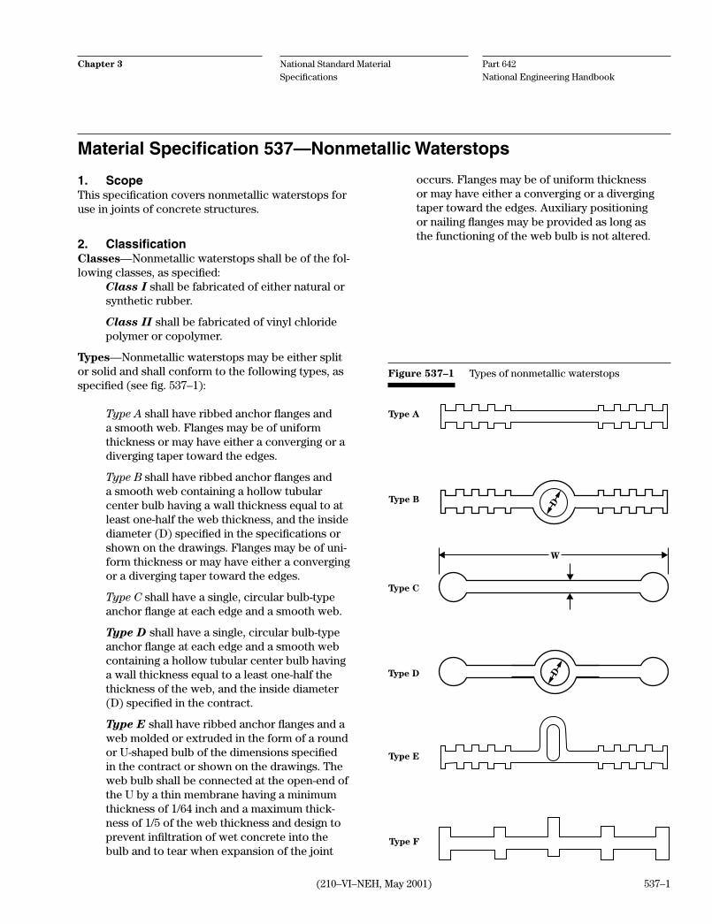
Part 642 National Engineering Handbook
National Standard Material Specifications
Chapter 3
(210–VI–NEH, May 2001) 537–1
1. ScopeThis specification covers nonmetallic waterstops for use in joints of concrete structures.
2. ClassificationClasses—Nonmetallic waterstops shall be of the fol-lowing classes, as specified:
Class I shall be fabricated of either natural or synthetic rubber.
Class II shall be fabricated of vinyl chloride polymer or copolymer.
Types—Nonmetallic waterstops may be either split or solid and shall conform to the following types, as specified (see fig. 537–1):
Type Ashallhaveribbedanchorflangesanda smooth web. Flanges may be of uniform thickness or may have either a converging or a diverging taper toward the edges.
Type Bshallhaveribbedanchorflangesanda smooth web containing a hollow tubular center bulb having a wall thickness equal to at least one-half the web thickness, and the inside diameter (D) specified in the specifications or shown on the drawings. Flanges may be of uni-form thickness or may have either a converging or a diverging taper toward the edges.
Type C shall have a single, circular bulb-type anchorflangeateachedgeandasmoothweb.
Type D shall have a single, circular bulb-type anchorflangeateachedgeandasmoothwebcontaining a hollow tubular center bulb having a wall thickness equal to a least one-half the thickness of the web, and the inside diameter (D) specified in the contract.
Type Eshallhaveribbedanchorflangesandaweb molded or extruded in the form of a round or U-shaped bulb of the dimensions specified in the contract or shown on the drawings. The web bulb shall be connected at the open-end of the U by a thin membrane having a minimum thickness of 1/64 inch and a maximum thick-ness of 1/5 of the web thickness and design to prevent infiltration of wet concrete into the bulb and to tear when expansion of the joint
occurs. Flanges may be of uniform thickness or may have either a converging or a diverging taper toward the edges. Auxiliary positioning ornailingflangesmaybeprovidedaslongasthe functioning of the web bulb is not altered.
Material Specification 537—Nonmetallic Waterstops
Figure 537–1 Types of nonmetallic waterstops
DD
W
Type A
Type B
Type C
Type D
Type E
Type F
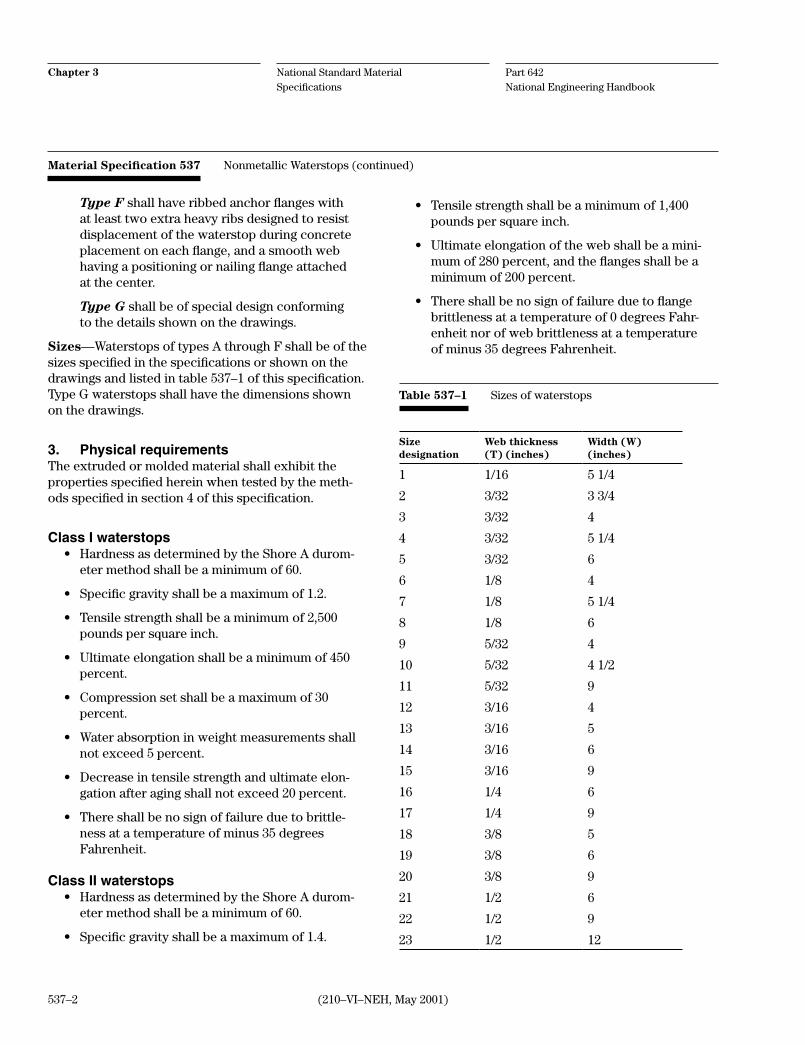
Part 642 National Engineering Handbook
National Standard Material Specifications
Chapter 3
(210–VI–NEH, May 2001)537–2
Material Specification 537 Nonmetallic Waterstops (continued)
Type Fshallhaveribbedanchorflangeswithat least two extra heavy ribs designed to resist displacement of the waterstop during concrete placementoneachflange,andasmoothwebhavingapositioningornailingflangeattachedat the center.
Type G shall be of special design conforming to the details shown on the drawings.
Sizes—Waterstops of types A through F shall be of the sizes specified in the specifications or shown on the drawings and listed in table 537–1 of this specification. Type G waterstops shall have the dimensions shown on the drawings.
3. Physical requirementsThe extruded or molded material shall exhibit the properties specified herein when tested by the meth-ods specified in section 4 of this specification.
Class I waterstops• HardnessasdeterminedbytheShoreAdurom-
eter method shall be a minimum of 60.
• Specificgravityshallbeamaximumof1.2.
• Tensilestrengthshallbeaminimumof2,500pounds per square inch.
• Ultimateelongationshallbeaminimumof450percent.
• Compressionsetshallbeamaximumof30percent.
• Waterabsorptioninweightmeasurementsshallnot exceed 5 percent.
• Decreaseintensilestrengthandultimateelon-gation after aging shall not exceed 20 percent.
• Thereshallbenosignoffailureduetobrittle-ness at a temperature of minus 35 degrees Fahrenheit.
Class II waterstops• HardnessasdeterminedbytheShoreAdurom-
eter method shall be a minimum of 60.
• Specificgravityshallbeamaximumof1.4.
• Tensilestrengthshallbeaminimumof1,400pounds per square inch.
• Ultimateelongationofthewebshallbeamini-mumof280percent,andtheflangesshallbeaminimum of 200 percent.
• Thereshallbenosignoffailureduetoflangebrittleness at a temperature of 0 degrees Fahr-enheit nor of web brittleness at a temperature of minus 35 degrees Fahrenheit.
Table 537–1 Sizes of waterstops
Sizedesignation
Web thickness (T) (inches)
Width (W)(inches)
1 1/16 5 1/4
2 3/32 3 3/4
3 3/32 4
4 3/32 5 1/4
5 3/32 6
6 1/8 4
7 1/8 5 1/4
8 1/8 6
9 5/32 4
10 5/32 4 1/2
11 5/32 9
12 3/16 4
13 3/16 5
14 3/16 6
15 3/16 9
16 1/4 6
17 1/4 9
18 3/8 5
19 3/8 6
20 3/8 9
21 1/2 6
22 1/2 9
23 1/2 12

Part 642 National Engineering Handbook
National Standard Material Specifications
Chapter 3
(210–VI–NEH, May 2001) 537–3
• Decreaseineithertensilestrengthorultimateelongation after accelerated extraction shall not exceed 15 percent.
• Resultsofalkaliexposure:
a. After immersion for 7 days, the sample shall exhibit no loss of weight and a maximum weight gain of 0.25 percent, and the hard-ness measured by the Shore A durometer method shall not vary more than 5 points either plus or minus from the untreated sample.
b. After immersion for 30 days, the sample shall exhibit no loss of weight and a maxi-mum weight gain of 0.40 percent, and the dimensions of the treated sample shall not vary by more than 1 percent from the un-treated sample.
4. Test methodsTesting shall be conducted by the methods cited herein. All cited test methods are included in ASTM as follows:
a. Hardness shall be determined by ASTM D 2240.
b. Specific gravity shall be determined by ASTM D 792.
c. Tensile strength shall be determined by ASTM D 412 for Class I waterstops and ASTM D 638 for Class II waterstops.
d. Ultimate elongation shall be determined by ASTM D 412 for Class I waterstops and ASTM D 638 for Class II waterstops.
e. Compression set shall be determined by ASTM D 395.
f. Water absorption shall be determined by ASTM D 570.
g. Tensile strength and ultimate elongation after aging shall be determined by ASTM D 412 for Class I waterstops and ASTM D 638 for Class II waterstops.
h. Brittleness shall be determined by ASTM D 746 for Class II waterstops.
i. Accelerated extraction shall be accomplished by procedures outlined by United States Army Corps of Engineers (USACE), Concrete Re-search Division (CRD) C 572 under the follow-ing conditions:
(1) Samples shall not be less than 1/16 inch nor more than 1/8 inch in thickness.
(2) The immersion medium shall be a solution prepared by dissolving 5 grams of chemi-cally pure sodium hydroxide and 5 grams of chemically pure potassium hydroxide in 1 liter of water.
(3) The samples shall be immersed in the medium for 14 days at a temperature of 145 degrees Fahrenheit, plus or minus 5 degrees Fahrenheit.
(4) During the period of immersion, air shall be gently bubbled through the medium from a 0.25-inch diameter glass tube at an approximate rate of one bubble per sec-ond.
(5) Fresh medium shall be provided each day.
(6) Samples need not be dipped in acetone.
j. The effects of alkalies shall be determined by USACE CRD C 572 under the following condi-tions:
(1) Sample shall have a maximum thickness of 0.25 inch.
(2) The immersion medium shall be as de-scribed for accelerated extraction above.
(3) Fresh medium shall be provided every 7days.
(4) The samples shall be immersed in the me-dium for 30 days.
(5) Samples need not be dipped in acetone.
5. ConditionWaterstops shall be extruded or molded in such a manner that the material is dense and homogeneous throughout and free from voids, tears, thins, inden-tations, or other imperfections. Unless otherwise
Material Specification 537 Nonmetallic Waterstops (continued)

Part 642 National Engineering Handbook
National Standard Material Specifications
Chapter 3
(210–VI–NEH, May 2001)537–4
specified, waterstops shall be symmetrical in shape and uniform in dimensions and shall be furnished in continuous strips a minimum length of 50 feet. Factory splices shall have a minimum tensile strength of 50 percent of the unspliced section.
6. Packaging and storingWaterstops shall be packaged and stored by methods that provide protection from prolonged exposure to direct sunlight and/or excessive heat.
Material Specification 537 Nonmetallic Waterstops (continued)

Part 642 National Engineering Handbook
National Standard Material Specifications
Chapter 3
(210–VI–NEH, May 2001) 538–1
1. ScopeThis specification covers the quality of material for metal waterstops as specified for reinforced concrete installation.
2. MaterialMetal waterstops shall be made of copper or galva-nized steel as specified. Waterstops that require form-ing of the metal involving sharp bends shall be made of copper, which shall be soft and pliable so bending to an inside radius equal to its thickness without crack-ing will occur at temperatures less than 180 degrees Fahrenheit.
3. QualityMetal for waterstops shall conform to the require-ments of the applicable ASTM Standard:
• Copper—ASTMSpecificationB152
• Zinc-coated(galvanized)steel—ASTMSpecifi-cation A 653
Material Specification 538—Metallic Waterstops

(210–VI–NEH, May 2001)

Part 642 National Engineering Handbook
National Standard Material Specifications
Chapter 3
539–1(210–VI–NEH, January 2009)
1. ScopeThis specification covers the quality of steel reinforce-ment for reinforced concrete.
2. QualityAllreinforcementshallbefreefromlooseorflakyrust,soil, oil, grease, paint, or other deleterious matter.
Steel bars for concrete reinforcement shall be grade 40, 50, or 60 deformed bars conforming to one of the following specifications:
• Deformedandplainbillet-steelbarsforcon-crete reinforcement—ASTM A 615
• Rail-steeldeformedbarsforconcretereinforce-ment—ASTM A 996
• Axle-steeldeformedbarsforconcreterein-forcement—ASTM A 996
Dowels shall be plain round bars conforming to the same specifications listed above for steel bars.
Fabricated deformed steel bar mats for concrete reinforcement shall conform to the requirements of ASTM A 184.
Plain steel welded wire reinforcement for concrete reinforcement shall conform to the requirements of ASTM A 185.
Deformed steel welded wire reinforcement for concrete reinforcement shall conform to the require-ments of ASTM A 497.
Epoxy-coated steel bars for concrete reinforcement shall conform to the requirements of ASTM A 775.
3. Dimensions of welded wire reinforcementGauges, diameters, spacing, and arrangement of wires for welded steel wire fabric shall be as defined for the specified style designations.
4. StorageSteel reinforcement inventories at the site of the work shall be stored above the ground surface on platforms, skids, or other supports and shall be kept clean and protected from mechanical injury and corrosion.
Material Specification 539—Steel Reinforcement (for concrete)

(210–VI–NEH, January 2009)

Part 642 National Engineering Handbook
National Standard Material Specifications
Chapter 3
(210–VI–NEH, May 2001) 541–1
1. ScopeThis specification covers the quality of reinforced con-crete pressure pipe and fittings.
2. Manufacture and fabricationThe pipe, the material used in its manufacture, and the methods of fabrication shall conform to the require-ments of the following specifications applicable to the specified type of pipe.
Steel cylinder type, pre-stressed—AWWA Standard C301 for Pre-stressed Concrete Pressure Pipe, Steel Cylinder Type, for Water and Other Liquids.
Steel cylinder type, not pre-stressed—AWWA Standard C300 for Reinforced Concrete Pressure Pipe, Steel Cylinder Type, for Water and Other Liquids.
Noncylinder type, not pre-stressed—AWWA Stan-dard C302 for Reinforced Concrete Pressure Pipe, Non-Cylinder Type, for Water and Other Liquids.
Steel cylinder type, pre-tensioned—AWWA Stan-dard C303 for Concrete Pressure Pipe, Bar-Wrapped, Steel Cylinder Type for Water and Other Liquids.
Low head pressure pipe—ASTM Specification C 361.
The following specification sections shall not apply:
• AWWAC300andC301,sections1.5and1.6.
• AWWAC302andC303,sections4.2and4.3.
3. DesignThe actual pipe and fittings shall be designed by the manufacturer to withstand the specified external loads and internal pressures. Designs shall be by either of the following methods as applicable to the type of pipe specified:
Indirect design—ASTM C497 for Standard Test Method for Concrete Pipe, Manhole Sections, or Tile. Pipe design shall be based on the results of external crushing strength tests on a minimum 2-foot length of pipe or a specimen of equivalent size, design, and ma-terial. The test shall demonstrate the following bearing loads:
• ForpipemanufacturedaccordingtoASTMC361, AWWA C300, or AWWA C302, the load re-quired to produce a 0.01-inch crack 1 foot long.
• ForpipemanufacturedaccordingtoAWWAC301, the load required to produce a 0.001-inch crack 1 foot long or the load 10 percent greater than the specified three-edge bearing strength, whichever occurs first.
In lieu of actual testing for this contract, pipe design may be based on design curve previously approved and published by the Natural Resources Conservation Service.
Direct design—AWWA C304 for Design of Pre-Stressed Concrete Cylinder Pipe or AWWA Manual M9 for Concrete Pressure Pipe. Pipe design shall be based on structural analysis and design calculations.
Standard design—ASTM C361 for Reinforced Con-crete Low Head Pressure Pipe. Pipe design shall be as published in the standard.
Material Specification 541—Reinforced Concrete Pressure Pipe

Part 642 National Engineering Handbook
National Standard Material Specifications
Chapter 3
(210–VI–NEH, May 2001)541–2
4. Steel reinforcementThe steel reinforcements shall conform to the require-ments of the specifications cited in section 2 for the specified type of pipe except that elliptical reinforcing cages or other reinforcements that require special ori-entation of the pipe during placement are not allowed.
5. JointsThe pipe joints shall conform to the requirements of the applicable specification for the pipe. They shall be bell-and-spigot type or double-spigot-and-sleeve type and shall have a positive groove in the spigot to contain the rubber gasket. The size and shape of the groove shall be such that it prevents displacement of the gasket by either internal or external water pressure when the joint is in any position within the required range of movement capability. Joint sleeves, also referred to as collars or coupling bands, shall conform to the requirements for bell rings in the ap-plicable pipe specification.
The joints shall be constructed to permit relative movement of the adjoining pipe sections with no reduction of watertightness. The joint length and the limiting angle defining the required capability of rela-tive movement at each joint shall be no less than speci-fied.
Joint length refers to the permissible axial movement in the joint. It is defined as the maximum distance through which the spigot can move, relative to the bell or sleeve, from the fully engaged to the fully extended condition of the joint when the adjoining pipe sections are in parallel, concentric alignment. The joint is con-sidered to be fully engaged when the spigot is inserted as far as it will go into the bell or sleeve and is fully extended when it is inserted the least amount that will ensure full confinement of the gasket and complete watertightness.
Joint length specified for double-spigot joints refers to the permissible movement in each of the spigot-to-sleeve connections, not the sum of the two.
The limiting angle of the joint is defined as the maxi-mumdeflectionanglebetweenadjoiningpipesectionsthe joint will permit before the outer surface of the spigot comes into direct contact with inside of the mating bell or sleeve. If both spigot-to-sleeve connec-tions of a double-spigot joint permit angular move-ment, the limiting angle of the joint is the sum of the twodeflectionanglespermittedbythetwoconnec-tions.
6. GasketsThe pipe joint gaskets shall conform to the require-ments of the specifications cited in section 2 of this specification. They shall be endless rubber gaskets having circular cross section. The cross-sectional diameter of the gaskets shall conform to the pipe manufacturer's recommendation for the type and size of pipe furnished.
7. MarkingAll pipe sections and special fittings shall be marked by the manufacturer with the manufacturer's name or trademark, the date of manufacture, the nominal size, design head, design external load, and the structure site for which it was designed and manufactured.
8. CertificationAll component material and actual pipe fabrication shall be tested, inspected, and documented as pre-scribed in the manufacturing specifications for the type of pipe specified. All documentation as noted in the manufacturing specifications shall be submitted to the engineer. Documentation shall include current test reports on steel and steel wire reinforcing and compression tests of concrete used in the manufacture of the furnished pipe. Current tests are those that have been conducted within the last year.
Material Specification 541 Reinforced Concrete Pressure Pipe (continued)

Part 642 National Engineering Handbook
National Standard Material Specifications
Chapter 3
(210–VI–NEH, May 2001) 541–3
For pipe design based on actual external crushing strength tests, the engineer shall witness the actual test.
For pipe design based on published design curves, a copy of the appropriate design curve marked to show the resultant concrete core stress and correspond-ing three-edge bearing load and a specification sheet showing all data and dimensions necessary to calcu-late the resultant core stress for the pipe furnished shall be submitted to the engineer.
For pipe design based on structural analysis and calcu-lations, such analysis and calculations shall be submit-ted to the engineer. Printouts of such calculations by computer programs shall be sufficiently detailed to enable comparison with standardized procedures and methods.
Drawings, details, and descriptions of the pipe joints as necessary to show that the joint conforms to the specified requirements shall also be submitted.
Material Specification 541 Reinforced Concrete Pressure Pipe (continued)

(210–VI–NEH, May 2001)

Part 642 National Engineering Handbook
National Standard Material Specifications
Chapter 3
542–1(210–VI–NEH, November 2005)
1. ScopeThis specification covers the quality of nonreinforced and reinforced concrete culvert pipe.
2. Nonreinforced pipeNonreinforced concrete culvert pipe shall conform to the requirements of ASTM Specification C 14 for the class of pipe specified.
3. Reinforced pipeRound pipe—Round reinforced concrete culvert pipe shall conform to the requirements of ASTM Specifica-tion C 76 or ASTM C 655 for the class of pipe specified.
Arch pipe—Reinforced concrete arch culvert pipe shall conform to the requirements of ASTM Specifica-tions C 506 for the class of pipe specified.
Material Specification 542—Concrete Culvert Pipe
Elliptical pipe—Reinforced concrete elliptical cul-vert pipe shall conform to the requirements of ASTM Specification C 507 for the class of pipe specified.
4. Reinforced box sectionsReinforced concrete box sections shall be manufac-tured meeting the requirements of ASTM Specification C 1433.
5. Rubber gasket jointsWhen rubber gasket joints are specified, the joints and gaskets shall conform to the requirements of ASTM Specification C 443.

(210–VI–NEH, November 2005)

Part 642 National Engineering Handbook
National Standard Material Specifications
Chapter 3
(210–VI–NEH, May 2001) 543–1
1. ScopeThis specification covers the quality of nonreinforced concrete irrigation pipe, drainage pipe, and drain tile.
2. Irrigation pipeUnless rubber gasket joints are specified, nonrein-forced concrete irrigation pipe shall conform to the requirements of ASTM Specification C 118 for Stan-dard Concrete Irrigation Pipe.
3. Irrigation pipe with rubber gasket jointsNonreinforced concrete irrigation pipe with rubber gasket joints shall conform to the requirements of ASTM Specification C 505.
4. Drainage pipeNonreinforced concrete drainage pipe shall conform to the requirements of ASTM Specification C 118 for the class of pipe specified.
5. Perforated pipePerforated nonreinforced concrete pipe shall conform to the requirements of ASTM Specification C 444 for the class of pipe specified.
6. Drain tileConcrete drain tile shall conform to the requirements of ASTM Specification C 412 for the class of tile specified.
Material Specification 543—Nonreinforced Concrete Pipe

(210–VI–NEH, May 2001)
Part 642 National Engineering Handbook
National Standard Material Specifications
Chapter 3
544–1(210–VI–NEH, November 2005)
1. ScopeThis specification covers the quality of clay pipe and drain tile.
2. PipeStandard strength clay pipe and extra strength clay pipe shall conform to the requirements of ASTM Speci-fication C 700 for the specified class of pipe.
3. Perforated pipePerforated clay pipe shall conform to the requirements of ASTM Specification C 700 for the specified class of pipe.
4. Drain tileClay drain tile shall conform to the requirements of ASTM Specification C 4 for the specified class of tile. Perforated drain tile shall conform to the requirements of ASTM Specification C 4 for the specified class.
5. Compression joint materialCompression joints using material having resilient properties shall conform to the requirements of ASTM Specification C 425
Material Specification 544—Clay Pipe and Drain Tile

(210–VI–NEH, November 2005)

Part 642 National Engineering Handbook
National Standard Material Specifications
Chapter 3
547–1(210–VI–NEH, January 2009)
1. ScopeThis specification covers the quality of Poly Vinyl Chloride (PVC), Polyethylene (PE), High Density Poly-ethylene (HDPE), and Acrylonitrile-Butadiene-Styrene (ABS) plastic pipe, fittings, and joint materials.
2. MaterialPipe—The pipe shall be as uniform as commercially practicable in color, opaqueness, density, and other specified physical properties. It shall be free from vis-ible cracks, holes, foreign inclusions, or other defects. The dimensions of the pipe shall be measured as pre-scribed in ASTM D 2122.
Unless otherwise specified, the pipe shall conform to the requirements listed in this specification and the applicable reference specifications in table 547–2, the requirements specified in Construction Specification 45, Plastic Pipe, and the requirements shown on the drawings.
Fittings and joints—Fittings and joints shall be of a schedule, SDR or DR, pressure class, external load carrying capacity, or pipe stiffness that equals or exceeds that of the plastic pipe. The dimensions of fittings and joints shall be compatible with the pipe and measured in accordance with ASTM D 2122. Joint and fitting material shall be compatible with the pipe material. The joints and fittings shall be as uniform as commercially practicable in color, opaqueness, den-sity, and other specified physical properties. It shall be free from visible cracks, holes, foreign inclusions, or other defects.
Fittings and joints shall conform to the requirements listed in this specification, the requirements of the applicable specification referenced in the ASTM or AWWA specification for the pipe, the requirements specified in Construction Specification 45, and the requirements shown on the drawings.
Solvents—Solvents for solvent welded pipe joints shall be compatible with the plastic pipe used and shall conform to the requirements of the applicable specification referenced in the ASTM or AWWA specifi-cation for the pipe, fitting, or joint.
Gaskets—Rubber gaskets for pipe joints shall con-form to the requirements of ASTM F 477, Elastomeric Seals (Gaskets) for Jointing Plastic Pipe.
3. PerforationsWhen perforated pipe is specified, perforations shall conform to the following requirements unless oth-erwise specified in Construction Specification 45 or shown on the drawings:
a. Perforations shall be either circular or slots.
b. Circular perforations shall be 1/4 ± 1/16-inch diameter holes arranged in rows parallel to the axis of the pipe. Perforations shall be evenly spaced along each row such that the center-to-center distance between perforations is not less than eight times the perforation diameter. Perforations may appear at the ends of short and random lengths. The minimum perforation opening per foot of pipe shall be as shown in table 547–1.
Material Specification 547—Plastic Pipe
Table 547–1 Perforations
Nominal pipe size(in)
Minimum number of rows Minimumopening/foot(in2)
circular slot
4 2 2 0.22
6 4 2 0.44
8 4 2 0.44
10 4 2 0.44
12 6 2 0.66

Part 642 National Engineering Handbook
National Standard Material Specifications
Chapter 3
547–2 (210–VI–NEH, January 2009)
Rows shall be arranged in two equal groups at equal distance from the bottom on each side of the vertical centerline of the pipe. The lower-most rows of perforations shall be separated by an arc of not less than 60 degrees or more than 125 degrees. The uppermost rows of perfora-tions shall be separated by an arc not to exceed 166 degrees. The spacing of rows between these limits shall be uniform. The minimum number of rows shall be as shown in table 547–1.
c. Slot perforations shall be symmetrically located in two rows, one on each side of the pipe cen-terline. Slot perforations shall be located within the lower quadrants of the pipe with slots no wider than 1/8 inch and spaced not to exceed 11 times the perforation width. Minimum perfo-ration opening per lineal foot of pipe shall be as shown in table 547–1.
d. On both the inside and outside of the pipe, perforations shall be free of cuttings or frayed edges and of any material that would reduce the effective opening.
Material Specification 547 Plastic Pipe (continued)

Part 642 National Engineering Handbook
National Standard Material Specifications
Chapter 3
547–3(210–VI–NEH, January 2009)
Table 547–2 Pipe specification
Pipe Specification
Poly vinyl chloride (PVC) pipe
Plastic pipe - Schedules 40, 80, 120 ...................................................................................................................ASTM D 1785 ASTM D 2466Pressure rated pipe - SDR Series .......................................................................................................................AWWA C 900 ASTM D 2241Plastic drain, waste, and vent pipe and fittings ...............................................................................................ASTM D 2665Joints for IPS PVC pipe using solvent weld cement........................................................................................ASTM D 2672Composite sewer pipe .........................................................................................................................................ASTM D 2680Type PSM PVC sewer pipe and fittings .............................................................................................................ASTM D 3034Large-diameter gravity sewer pipe and fittings ................................................................................................ASTM F 679Smooth-Wall Underdrain Systems for Highway, Airport, and Similar Drainage .........................................ASTM F 758Profile gravity sewer pipe and fittings based on controlled inside diameter ...............................................ASTM F 794Corrugated sewer pipe with a smooth interior and fittings ...........................................................................ASTM F 949Pressure pipe, 4-inch through 12-inch for water distribution ........................................................................AWWA C 900Water transmission pipe, nominal diameters 14-inch through 36-inch .........................................................AWWA C 905
Polyethylene (PE) plastic pipeSchedule 40...........................................................................................................................................................ASTM D 210412 to 60-inch annular corrugated profile-wall polyethylene (PE) pipe and fittings ....................................ASTM F 2306SIDR-PR based on controlled inside diameter.................................................................................................ASTM D 2239Schedules 40 and 80 Based on outside diameter .............................................................................................ASTM D 2447SDR-PR based on controlled outside diameter ...............................................................................................ASTM D 3035 High density polyethylene (HDPE) plastic pipePlastic pipe and fittings .......................................................................................................................................ASTM D 3350SDR-PR based on controlled outside diameter ...............................................................................................ASTM F 714Heat joining polyolefin pipe and fittings ...........................................................................................................ASTM D 2657
Acrylonitrile-butadiene-styrene (ABS) pipePlastic pipe, schedules 40 and 80 ......................................................................................................................ASTM D 1527Composite sewer pipe .........................................................................................................................................ASTM D 2680
Material Specification 547 Plastic Pipe (continued)

(210–VI–NEH, January 2009)

Part 642 National Engineering Handbook
National Standard Material Specifications
Chapter 3
548–1(210–VI–NEH, January 2009)
1. ScopeThe specification covers the quality of corrugated polyethylene pipe and fittings.
2. PipeCorrugated polyethylene pipe shall conform to the re-quirements of ASTM F 405, ASTM F 667, ASTM F 894, AASHTO M 252, or AASHTO M 294 for the appropriate pipe sizes and fittings.
3. FittingsASTM F 405 3-6 inch diameter pipe and fittings
ASTM F 667 8-, 10-, 12-, 15-, 18-, and 24-inch diam-eter pipe and fittings
ASTM F 894 18- to 120-inch diameter pipe and fittings
AASHTO M 252 3- to 10-inch diameter pipe and fit-tings
AASHTO M 294 12- to 36-inch diameter pipe and fit-tings
Material Specification 548—Corrugated Polyethylene Pipe

(210–VI–NEH, January 2009)

Part 642 National Engineering Handbook
National Standard Material Specifications
Chapter 3
551–1(210–VI–NEH, November 2005)
1. ScopeThis specification covers the quality of zinc-coated, aluminum-coated, aluminum-zinc alloy-coated, and polymer-coated corrugated steel pipe and fittings.
2. PipeAll pipe shall be metallic zinc-coated, aluminum-coated, or aluminum-zinc alloy-coated corrugated steel pipe and fittings conforming to the requirements of ASTM A 742, A 760, A 761, A 762, A 849, A 875, A 885, and A 929 for the specified type, class, fabrication of pipe and coating, and to the following additional requirements:
a. When closed riveted pipe is specified:
(1) Pipe shall be fabricated with circumfer-ential seam rivet spacing that does not exceed 3 inches except that 12 rivets are sufficient to secure the circumferential seams in 12-inch pipe.
(2) Longitudinal seams that will be within the coverage area of a coupling band, the rivetsshallhaveflatheadsortherivetsand holes shall be omitted and the seams shall be connected by welding to provide a minimum of obstruction to the seating of the coupling bands.
b. Double riveting or double spot welding for pipe less than 42 inches in diameter may be required. When double riveting or double spot welding is specified, the riveting or welding shall be performed in a manner specified for pipe 42 inches or greater in diameter.
3. CoatingsCoatings described herein, unless otherwise specified, equally refer to the inside and outside pipe surfaces.
When coatings in addition to metallic coatings are specified, they shall conform to the requirements of ASTM A 742, A 760, A 761, A 762, A 849, A 875, A 885, and A 929 for the specified type.
Polymer-coated pipe, unless otherwise specified on the drawings or in the construction specifications, shall be coated on each side with a minimum thickness of 0.01 inches (10 mils), designated as grade 10/10 in ASTM A 762.
4. Coupling bandsCoupling bands are to be provided for each section of pipe. The hardware for fastening the coupling band tightly to the connecting pipe shall be fabricated to permit tightening sufficiently to provide the required joint tensile strength and, if required, watertightness without failure of its fastening.
Gaskets, if specified, are to be provided for each coupling band. The fabrication of coupling bands and fastening hardware, in addition to the above, shall be sufficient to provide the required gasket seating with-out warping, twisting, or bending.
5. FittingsFittings shall be fabricated from steel conforming to ASTM A 742, A 849, A 875, A 885, and A 929. The coat-ing of fittings shall be the same as that specified for the contiguous corrugated coated pipe.
Welded surfaces and adjacent surfaces damaged duringweldingshallbetreatedbyremovingallfluxresidue and weld splatter. The affected surfaces shall be cleaned to bright metal by sand blasting, power disk sanding, or wire brushing. The cleaned area shall extend at least 0.5 inch into the undamaged section of the coated area. Repair and coating application of damaged and uncoated pipe surface areas shall be in accordance with ASTM A 780.
Material Specification 551—Coated Corrugated Steel Pipe

(210–VI–NEH, November 2005)

Part 642 National Engineering Handbook
National Standard Material Specifications
Chapter 3
(210–VI–NEH, May 2001) 552–1
1. ScopeThis specification covers the quality of aluminum cor-rugated pipe and fittings.
2. PipeAluminum corrugated pipe and fittings shall conform to the requirements of ASTM B 745, B 746, or B 790 for the specified pipe sheet thickness, shape type, fabrica-tion methods, and the following additional require-ments:
a. When close-riveted pipe is specified: (1) Pipe shall be fabricated with circumfer-
ential seam rivet spacing that does not exceed 3 inches except that 12 rivets are sufficient to secure the circumferential seams in 12-inch pipe.
(2) Longitudinal seams that will be within the coverage area of a coupling band, the rivetsshallhaveflatheadsortherivetsand holes shall be omitted and the seams shall be connected by welding to provide a minimum of obstruction to the seating of the coupling bands.
3. CoatingsBituminous coatings, when specified, shall conform to the requirements of ASTM A 849.
4. Coupling bandsCoupling bands are to be provided for each section of pipe. The hardware for fastening the coupling band tightly to the connecting pipe shall be fabricated to permit tightening sufficiently to provide the required joint tensile strength and, if required, watertightness without failure of its fastening.
Gaskets, if specified, are to be provided for each cou-pling band. The fabrication shall also be sufficient to provide the required gasket seating without warping, twisting, or bending.
Gaskets provided with connecting bands meeting requirements for special joints in erodible soil condi-tions shall be as specified in ASTM A 762.
5. FittingsFittings shall be fabricated from sheet aluminum meet-ing the requirements contained in ASTM B 744. The coating for fittings shall be the same as that specified for the contiguous corrugated aluminum pipe.
Fittings that are welded during fabrication shall be accomplished in a good workmanshiplike manner resulting in a continuous smooth surface finish. Alu-minum welding electrodes used shall conform to the requirements of American Welding Society (AWS) specification AWS A5.10, "Specification for Aluminum and Aluminum Alloy Welding Rods and Bare Elec-trodes." Welded surfaces and adjacent surfaces dam-aged during welding shall be treated by removing all weld splatter. The affected surface shall be cleaned to bright metal by sand blasting, power disk sanding, or wire brushing. The cleaned area shall extend at least 0.5 inch into the undamaged section of coated area. Within 24 hours of completion of surface preparation all treated surfaces shall be painted with two coats of a chromate rich primer and allowed to fully dry before exposure to weathering conditions.
Aluminum surfaces fabricated that will have contact with steel, iron, or other metals shall be coated with a zinc-chromate primer and allowed to fully dry before final installation.
Material Specification 552—Aluminum Corrugated Pipe

(210–VI–NEH, May 2001)

Part 642 National Engineering Handbook
National Standard Material Specifications
Chapter 3
(210–VI–NEH, May 2001) 553–1
1. ScopeThis specification covers the quality of ductile-iron pipe and fittings.
2. PipeDuctile-iron pipe shall conform to the requirements of ANSI/AWWA C151/A21.51, Ductile-Iron Pipe, Cen-trifugally Cast in Metal Molds or Sand-Lined Molds for Water or Other Liquids, and ANSI/AWWA C115/A21.15, Flanged Ductile-Iron Pipe with Threaded Flanges.
3. FittingsDuctile-iron pipe fittings shall conform to the require-ments of ANSI/AWWA C110/A21.10, Ductile-Iron and Gray-Iron Fittings, 3-inch through 48-inch, for Water and Other Liquids, and ANSI/AWWA C153/A21.53, Ductile-Iron Compact Fittings, 3-inch through 12-inch, for Water and Other Liquids.
4. JointsRubber-gasket joints for ductile-iron pipe and fittings where either mechanical or push-on joints are used shall conform to the requirements of ANSI/AWWA C111/A21.11, Rubber-Gasket Joints for Ductile-Iron and Gray-Iron Pressure Pipe and Fittings.
5. LiningInterior lining for ductile-iron pipe and fittings shall conform to the requirements of ANSI/AWWA C104/A21.4, Cement Mortar Lining for Ductile-Iron Pipe and Fittings for Water.
6. EncasementEncasement for ductile-iron pipe and fittings shall con-form to the requirements of ANSI/AWWA C105/A21.5-88, Polyethylene Encasement for Ductile-Iron Pipe for Water and Other Liquids.
Material Specification 553—Ductile from Pipe

(210–VI–NEH, May 2001)
Part 642 National Engineering Handbook
National Standard Material Specifications
Chapter 3
(210–VI–NEH, May 2001) 554–1
1. ScopeThis specification covers the quality of steel pipe and fittings.
2. PipeSteel pipe shall conform to the requirements of the ap-plicable specification listed below for the kind of pipe and the type, weight, grade, and finish specified:
Pipe ASTM specification
Steel, black and hot-dipped, zinc- A 53 coated welded and seamlessSteel, electric-fusion (ARC)-welded A 134 (sizes NPS 16 and over)Electric-resistance-welded steel A 135Electric-fusion (ARC)-welded steel A 139 (NPS 4 and over)
AWWA standard
Steel water pipe, 6 inches and larger C 200
3. FittingsFittings shall conform to the requirements for the types and kinds specified.
Fittings ASTM specification
Heat-treated carbon steel fittings A 858 for low-temperature and corrosive serviceThreaded couplings, steel, black or A 865 zinc-coated (galvanized) welded or seamless, for use in steel pipe joints
Material Specification 554—Steel Pipe

(210–VI–NEH, May 2001)

Part 642 National Engineering Handbook
National Standard Material Specifications
Chapter 3
571–1(210–VI–NEH, January 2009)
1. ScopeThis specification covers the quality of metal slide gates for water control.
2. Class and type of gateThe class of gate is expressed as a numerical symbol composed of the seating head and unseating head. The two numbers are separated by a hyphen with the seat-ing head listed first. For this purpose, the heads shall be expressed in terms of feet of water. Gates shall be of the specified types as defined:
Light dutyType MLS-1 Cast iron with cast iron seat facingsType MLS-2 Fabricated metal
Moderate dutyType MMS-1 Cast iron with bronze seat facings, cast
iron or galvanized structural steel guides, and galvanized steel, bronze, or stainless steel fasteners.
Type MMS-2 Cast iron with bronze seat facings, cost iron or stainless steel guides, and bronze or stainless steel fasteners. Guides and fas-teners are stainless steel, when specified.
Heavy dutyType MHS-1 Have gray cast iron slides, frames,
guides, and yokes, and are fitted with bronze seat facings, bronze wedges and wedge blocks or wedge seat facings, and bronze stem blocks or thrust nuts; bronze or stainless steel fasteners; and cold rolled steel stems except where stainless steel stems are specified.
Type MHS-2 Have gray cast iron slides, frame, guides, and yokes, and are fitted with stainless steel seat facings, wedges, wedge seat facings, stems and fasteners; and auste-nitic cast iron stem blocks or thrust nuts.
Type MHS-3 Have austenitic gray cast iron slides, frames, guides, and yokes, and are fitted with nickel-copper alloy seat facings, wedges, wedge seat facings, stems and fasteners; and austenitic cast iron stem blocks or thrust nuts.
3. Quality of materialMaterial for slide gates and appurtenances shall con-form to the requirements of the applicable specifica-tions listed below for the alloy, grade, type, or class of material and the condition and finish appropriate to the structural and operational requirements.
Material ASTM specification
Cast iron and gray cast iron .................... A 48, Class 30 A 126, Class BAustenitic cast iron................................................. A 436Structural steel shapes, plates, .............................. A 36 and barsCold rolled steel ...................................................... A 108Carbon steel bars .....................................A 108 or A 575Stainless steel ..............................................A 167, A 276, A 582; Type 302, 303, 304, or 304LCastings, nickel and nickel alloy .......................... A 494Carbon steel sheets and strips ............................ A 1011Zinc-coated carbon steel sheets.............A 653 or A 924Bronze bar, rods, shapes .............................B 21 or B 98Naval bronze.............................................................. B 21Phosphor bronze ......................................B 103 or B 139Manganese bronze ...................................B 138 or B 584Silicon bronze.............................................B 98 or B 584Cast bronze .............................................................. B 584Nickel-copper alloy plate, sheet, ......................... B 127 stripNickel-copper alloy rod or bar .............................. B 164Rubber for gaskets and seals D 395, D 412, D 471, D 572, or D 2240
Galvanizing (zinc coating) shall conform to the re-quirements of Material Specification 582.
Material Specification 571—Slide Gates

Part 642 National Engineering Handbook
National Standard Material Specifications
Chapter 3
571–2 (210–VI–NEH, January 2009)
4. Fabricated metal gates (light duty gates)Fabricated metal gates shall be built to withstand the seating head expressed by the gate class designation. Unless otherwise specified, the gates shall be galva-nizedsteelwithflat-backframes.
5. Cast iron gates (light duty gates)The frame shall be cast iron of the specified type. The front face shall be machined to receive the gate guides.
The gate slide shall be cast iron and shall be fabri-cated to withstand the seating and unseating heads expressed by the gate class designation as defined in section 2 of this specification.
Grooves shall be cast on the vertical sides of the slide to match the guide angles.
The gates guides shall be galvanized structural steel and shall be fabricated to withstand the total thrust of the gate slide from water pressure and wedge action under maximum operating conditions.
Wedges and wedge seats shall have smooth bearing surfaces. Wedges may be cast as integral parts of the slide. Removable wedges and wedge seats shall be fas-tened to the slide, frame, or guides by means of suit-able studs, screws, or bolts and shall be firmly locked in place after final adjustment. Each interacting set of wedge and wedge seat shall be adjustable as needed to ensure accurate and effective contact. Adjusting bolts or screws shall be bronze or galvanized steel.
Seat facings shall be machined to a smooth finish to ensure proper watertight contact.
6. Frame or seat (moderate and heavy duty gates)The frame shall be cast iron and of the specified type. The front face shall be machined to receive the gates guides, and the rear face shall be machined as required to match the specified attaching means. For heavy duty gates, a dovetailed groove shall be machined on the perimeter of the front face to receive the seat facing.
7. Gate slide (moderate and heavy duty gates)The gate slide shall be cast iron, rectangular in shape, and shall have horizontal and vertical stiffening ribs of sufficient section to withstand the seating and unseat-ing heads expressed by the gate class designation as defined in section 2 of this specification. For heavy duty gates, a dovetailed groove shall be machined on the perimeter of the slide face to receive the seat facing.
Tongues shall be machined on the vertical sides of the slide along its entire height to match the guide grooves and angles with a maximum clearance of 1/16 inch for gates smaller than 54 inches by 54 inches, and 1/8 inch for larger gates.
A nut pocket with reinforcing ribs shall be integrally cast on the vertical centerline and above the horizontal centerline of the slide. The pocket shall be of a shape adequatetoreceiveaflat-backedthrustnutorstemblock and shall be built to withstand the opening and closing thrust of the stem.
8. Gate guides (moderate and heavy duty gates)The gate guides shall be built to withstand the total thrust of the gate slide from water pressure and wedge action. The gate guides shall be cast iron for heavy duty gates.
Grooves shall be machine-in cast iron guides to re-ceive the tongue on the gate slide throughout the entire length of the guide.
The guides shall be of adequate length to retain a mini-mum of one-half the height of the gate slide when the gate is fully opened.
9. Wedges and wedge seats (moderate and heavy duty gates)Pads for supporting wedges, wedge seats (or blocks), and wedge loops (or stirrups) shall be cast as integral parts of the gate frame, slide, or guides and shall be accurately machined to receive those parts.
Material Specification 571 Slide Gates (continued)

Part 642 National Engineering Handbook
National Standard Material Specifications
Chapter 3
571–3(210–VI–NEH, January 2009)
Wedges and wedge seats shall have smooth bear-ing surfaces for moderate duty gates and shall have machine finish bearing surfaces for heavy duty gates. Removable wedges may be cast as integral part of the slide for moderate duty gates. Wedges shall be fastened to the gate slide, frame, or guides with suit-able studs, screws, or bolts and shall be firmly locked in place after final adjustment. Each interacting set of wedge and wedge seat shall be adjustable as needed to ensure accurate and effective contact.
10. Seat facingModerate duty gates—Seat facings shall be ma-chined to a smooth finish to ensure proper watertight contact. Bronze facings shall be securely attached by welding or other approved methods.
Heavy duty gates—Seat facings shall be pressed or impacted into the machined dovetailed grooves on the gate slide and frame and machined to a smooth finish to ensure proper watertight contact.
11. YokeWhen a self-contained gate is specified, the yoke shall be of such design as to withstand the loads resulting from normal operation of the gate. For moderate and heavy duty gates, cast iron yokes shall be provided with machined pads for connecting to the ends of gate guides and to receive the stem thrust cap or hand-wheel lift.
12. Flush bottom seal (heavy duty gate)Whenaflushbottomsealinggatesisspecified,asolid,square-corner type rubber seal shall be provided at the bottom of the gate opening. It shall be securely attached either to the bottom of the slide or to the frame. Metal surfaces bearing on the rubber seal shall be smooth and rounded as necessary to prevent cut-ting of the seal during gate operation.
13. Gate stem and lift (or hoist)The gate stem and lift/hoist shall be of the specified type, size, and capacity and, if hand operated, shall be capable of moving the gate slide under normal condi-tions, following unseating from the wedging device, with a pull on the handwheel or crank of not more than 25 pounds with the specified seating and/or un-seating head of water against the gate.
Unless otherwise specified, the stem shall be carbon steel and shall be furnished in sections as necessary to permit reasonable ease in installation. Couplings shall be bolted, pinned, or keyed to the stem. The stem shall be furnished with rolled or machine-cut 29 degree Acme threads of sufficient length to completely open the gate. The threads shall be smooth and of uniform lead and cross-section, such that the nut can travel the full length without binding or excessive friction. For moderate and heavy duty gates, the stem shall be threaded for connection to the stem block or thrust nut on the gate slide.
The lift shall be compatible with the type of stem furnished. Unless otherwise specified, the lift nut shall be cast bronze for light and moderate duty gates and cast manganese bronze for heavy duty gates and shall be fitted with ball or roller thrust bearings designed to withstand the normal thrust developed during open-ing and closing of the gate at the maximum operat-ing heads. All gears, sprockets, and pinions shall be machine-cut, with ratios and strength adequate to withstand expected operating loads. Sufficient grease fittings shall be provided to allow lubrication of all moving parts. An arrow and the word "open" shall be cast on the rim of the handwheel or on the lift housing to indicate the direction of gate opening. Unless other-wise specified, the lift for the nonrising-stem gate shall be provided with an indicator capable of showing both when the gate is fully open and when it is fully closed for the moderate and heavy duty gates.
Provisions shall be made to prevent stem rotation within the stem block or thrust nut or at the connec-tion of the gate slide.
Material Specification 571 Slide Gates (continued)
Part 642 National Engineering Handbook
National Standard Material Specifications
Chapter 3
571–4 (210–VI–NEH, January 2009)
Stop collars shall be provided to prevent overtravel in opening and closing the gate.
14. Stem guidesUnless otherwise specified, stem guides shall be cast iron for light duty gates and cast iron with bronze bushed collars for moderate and heavy duty gates. They shall be fully adjustable in two directions.
15. Wall thimble (moderate and heavy duty gates)When a wall thimble is specified, it shall be of the same cast iron used in the gate frame and of the sec-tion,type,anddepthspecified.Thefrontflangeshallbe machined to match the gate frame and drilled and tapped to accurately receive the gate attachment studs.
Gaskets or mastic to be installed between the thimble and the gate frame shall conform to the recommenda-tions of the gate manufacturer and shall be furnished with the thimble.
16. FastenersUnless otherwise specified, all anchor bolts and other fasteners shall be galvanized steel or bronze for light duty gates; galvanized steel or stainless steel or bronze for moderate duty gates; and, of the quality and size as recommended by the gate manufacturer for heavy duty gates. All anchor bolts, assembly bolts, screws, nuts, and other fasteners shall be of ample section to withstand the forces created by operation of the gate while subjected to the specified seating and unseating heads. Anchor bolts shall be furnished with two nuts to facilitate installation.
17. Installation instructionsBefore installation, the contractor shall provide the engineer with the manufacturer's complete installation data, instructions for adjustments, and drawings or templates showing the location of all anchor bolts for each gate.
18. PaintingWhen specified, gates and accessories shall be painted by the designated paint system.
19. CertificationThe supporting data submitted to the engineer shall include the name of the manufacturer, the manufac-turer's model number (for standard catalogue items), or the seating and unseating heads for which the gate is designed together with such drawings and specifica-tions as may be necessary to show that the gate con-forms to the requirements of this specification.
Material Specification 571 Slide Gates (continued)

Part 642 National Engineering Handbook
National Standard Material Specifications
Chapter 3
572–1(210–VI–NEH, January 2009)
1. ScopeThisspecificationcoversthequalityofmetalflapgatesfor water control.
2. Class and type of gateThe class of gate is expressed as the numerical value of the seating head that the gate must be built to with-stand. For this purpose, the head shall be expressed in terms of feet of water measured to the center of the gate. Gates shall be of the specified type as defined below:
Light dutyType MLF–1—Cast iron or cast steel fitted with un-bushed linkage systems and galvanized steel fasteners, or with bronze bushed linkage systems and bronze or stainless steel fasteners.
Moderate dutyType MMF–1—Cast iron or cast steel fitted with bronze seat facings, bronze bushed linkage systems, and bronze or stainless steel fasteners.
Heavy dutyType MHF–1—Havegraycastironframesandflapsand are fitted with naval bronze seat facings, gray cast iron or high-strength bronze hinge arms, bronze bush-ings, bronze hinge pins, and bronze fasteners.
Type MHF–1R—The same as Type MHF-1 gates except that the frame is fitted with a rubber seat facing instead of a metal seat facing.
Type MHF–2—Havegraycastironframesandflapsand are fitted with stainless steel seat facings, gray cast iron or stainless steel hinge arms, and stainless steel bushings, hinge pins, and fasteners.
Type MHF–2R—The same as Type MHF-2 gates except that the frame is fitted with a rubber seat facing instead of a metal seat facing.
Type MHF–3—Have austenitic gray cast iron frames, flapsandhingearmsandarefittedwithnickel-copperalloy seat facings, bushings, hinge pins, and fasteners.
Type MHF–3R—The same as Type MHF-3 except that the frame is fitted with a rubber seat facing instead of a metal seat facing.
3. Quality of materialMaterialinflapgatesandappurtenancesshallconformto the requirements of the applicable specifications listed below for the alloy, grade, type, or class of mate-rial and the condition and finish appropriate to the structural and operational requirements:
Material ASTM specifications
Cast iron and gray cast iron ............... A 48, Class 30, or A 126, Class BCast steel ......................................................A 27 or A 148Structural steel shapes, plates, ............................... A 36 and barsCarbon steel bars ......................................A 108 or A 575Stainless steel ..........................................A 167, A 276, or A 582; Type 302, 303, 304, or 304LAustenitic gray cast iron ......................................... A 436Castings, nickel and nickel-alloy ........................... A 494Carbon steel sheets and strips ............................. A 1011Bronze bar, rods, shapes, and ....................B 21 or B 98 naval bronzeRed brass .................................................................... B 43Silicon bronze..............................................B 98 or B 584Phosphor bronze .......................................B 103 or B 139Manganese bronze ....................................B 138 or B 584Nickel-copper alloy plate, sheet, .......................... B 127 stripNickel-copper alloy rod, bar ................................... B 164Cast bronze ............................................................... B 584Rubber gaskets and seals .......................... D 395, D 412, D 471, D 572, or D 2240
Material Specification 572—Flap Gates, Metal

Part 642 National Engineering Handbook
National Standard Material Specifications
Chapter 3
572–2 (210–VI–NEH, January 2009)
4. FrameThe frame shall be cast iron or cast steel for light and moderate duty gates and as specified for heavy duty gates, and of the specified type. For moderate and heavy duty gates, the rear face shall be machined as required to match the specified attaching means. For the heavy duty gate, a groove shall be matched on the perimeter of the front face to receive the seat facing.
5. FlapForlightandmoderatedutygates,theflapshallbecast iron or cast steel and shall be built to withstand the seating head expressed by the gate class designa-tion as defined in section 2 of this specification.
Forheavydutygates,theflapshallbebuilttowith-stand the seating head expressed by the gate class des-ignation as defined in section 2 of this specification. A groove shall be machined on the perimeter of the face to receive the seat facing.
6. Linkage systemThelinkagesystembywhichtheflapismountedontothe frame shall be double-pivoted type for gates more than 8 inches in diameter. It shall be designed to pre-venttheflapfromfoldinginsideoftheseatandwedg-ing in the open position. For the moderate heavy duty gates, the top pivot shall be so designed as to allow adjustment of gate alignment and sensitivity.
7. Seat facingsLight duty gates—All facings shall be machined to a smooth finish to insure proper contact.
Moderate duty gates—Seat facings shall be securely attached by welding or other approved means and ma-chined to a smooth finish to ensure proper contact.
Heavy duty gates—Metal facings shall be pressed or impactedintomachineddovetailedgroovesontheflapand frame (or securely attached in the seat grooves by means of studs, set screws, or other approved means)
and machined to a smooth finish to ensure proper con-tact. Rubber facings shall be pressed into a dovetailed groove in the frame.
8. Wall thimbleWhere a wall thimble is specified for moderate and heavy duty gates, it shall be of the same cast iron used in the gate frame and of the section, type, and depth specified.Thefrontflangeshallbemachinedtomatchthe gate frame and drilled and tapped to accurately receive the gate attachment studs.
Gaskets or mastic to be installed between the thimble and the gate frame shall conform to the recommenda-tions of the gate manufacturer and shall be furnished with the thimble.
9. GalvanizingUnless otherwise specified, cast steel and fabricated steel parts shall be galvanized in accordance with Material Specification 582.
10. PaintingWhen specified, gates and accessories shall be painted by the designated paint system.
11. Installation instructionsThe contractor shall provide the engineer with the manufacturer's complete installation data, instructions for adjustments, and drawings or templates showing the location of anchor bolts for each gate.
12. CertificationThe supporting data submitted to the engineer shall include the name of the manufacturer, the manufac-turer's model number (for standard catalogue items), or the seating head for which the gate is designed together with such drawings and specifications as may be necessary to show that the gate conforms to the requirements of this specification.
Material Specification 572 Flap Gates, Metal (continued)

Part 642 National Engineering Handbook
National Standard Material Specifications
Chapter 3
(210–VI–NEH, May 2001) 573–1
1. ScopeThis specification covers the quality of radial (Tainter) gates for water control.
2. Quality of materialMaterial in radial gates and appurtenances shall con-form to the requirements of the applicable specifica-tions listed below for the alloy, grade, type, or class of material and the condition and finish appropriate to the structural and operational requirements:
Material ASTM specifications
Cast iron ................................................ A 48, Class 30, or A 126, Class BCast steel ......................................................A 27 or A 148Structural steel shapes, plates ................................ A 36 and barsCarbon steel bars ......................................A 108 or A 575Stainless steel ..........................................A 167, A 276, or A 582; Type 302, 303, 304, or 304LZinc-coated steel sheets ...........................A 653 or A 924Bronze bar, rods, shapes ...............................B 21 or B98Cast bronze ............................................................... B 584
Galvanizing (zinc coating) shall conform to the re-quirements of Material Specification 582.
3. GatesUnless otherwise specified, the gates shall be fabri-cated from structural steel with skin plates made of smooth or corrugated iron or steel sheets. They shall conform to the dimensions shown on the drawings and shall be built to withstand the specified head. The curvature of the skin plate shall be concentric with the pivot pins or trunnions. Gates shall be supplied with pin bearings, pins, hoist, galvanized hoisting cable, and all anchor bolts. Unless otherwise specified, the pin bearings shall be cast iron and of the embedded type.
4. HoistHoists shall be of the worm-gear type and shall be equipped with hand crank or be power operated as specified on the drawings. Hoists shall be furnished complete with all lubricants, anchor bolts, and other appurtenances necessary for their installation and operation.
5. Rubber sealsEach gate shall be fitted with rubber seals along the side and bottom edges of the gate face. The seals shall be of the belt type or J type, as specified, and shall be designed to bear on the walls and bottom of the structure or on rubbing plates and sills to ensure a watertight fit when the gate is closed. When specified, a rubber seal shall also be provided at the top edge of the gate.
6. Installation instructionsBefore gate installation, the contractor shall provide the engineer with the manufacturer's complete instal-lation data, instructions for adjustments and drawings, or templates showing the location of anchor bolts and pin bearings for each gate.
7. PaintingGates and accessories shall be galvanized or painted with the specified paint system.
8. CertificationThe supporting data submitted to the engineer shall include the manufacturer's name and the hydraulic head for which the gate is designed together with such drawings and specifications as may be necessary to show that the gate conforms to the requirements of this specification.
Material Specification 573—Radial Gates

(210–VI–NEH, May 2001)

Part 642 National Engineering Handbook
National Standard Material Specifications
Chapter 3
581–1(210–VI–NEH, November 2005)
1. ScopeThis specification covers the quality of steel and alumi-num alloys.
2. Structural steel• Structuralsteelshallconformtotherequire-
ments of ASTM A 36.
• High-strengthlow-alloystructuralsteelshallconform to ASTM A 242 or A 588.
• Carbonsteelplatesofstructuralqualitytobebent, formed, or shaped cold shall conform the ASTM A 283, Grade C.
• Carbonsteelsheetsofstructuralqualityshallconform to ASTM Standard A 1011, Grade 40, or A 1008, Grade 40.
• Carbonsteelstripofstructuralqualityshallconform to ASTM Standard A 1011, Grade 36.
3. Commercial or merchant quality steelCommercial or merchant quality steel shall conform to the requirements of the applicable ASTM listed below:
Product ASTM standards
Carbon steel bars .......................... A 575, Grade M 1015 to Grade M 1031Carbon steel sheets .............................................. A 1011Carbon steel strips ................................................ A 1011Zinc-coated carbon steel sheets.............A 653 or A 924
4. Aluminum alloyAluminum alloy products shall conform to the require-ments of the applicable ASTM standard listed below. Unless otherwise specified, alloy 6061-T6 shall be used.
Product ASTM standards
Standard structural shape ..................................... B 308Extruded structural pipe and tube ....................... B 429Extruded bars, rods, shapes, and tubes ............... B 221Drawn seamless tubes ........................................... B 210Rolled or cold-finished bars, rods, and wire ...... B 211Sheet and plate ........................................................ B 209
5. BoltsSteel bolts shall conform to the requirements of ASTM Standard A 307. If high-strength bolts are specified, they shall conform to the requirements of ASTM A 325.
When galvanized or zinc-coated bolts are specified, the zinc coating shall conform to the requirements of ASTM Standard A 153 except that bolts 0.5 inch or less in diameter may be coated with electro-deposited zinc or cadmium coating conforming to the requirements of ASTM Standard B 633, Service Condition SC 3, or ASTM B 766, unless otherwise specified.
6. RivetsUnless otherwise specified, steel rivets shall conform to the requirements of ASTM Specification A 31, Grade B. Unless otherwise specified, aluminum alloy rivets shall be Alloy 6061 conforming to the requirements of ASTM Standard B 316.
7. Welding electrodesSteel welding electrodes shall conform to the require-ments of American Welding Society Specification AWS A5.1, "Specification for Mild Steel Covered Arc-Weld-ing Electrodes," except that they shall be uniformly and heavily coated (not washed) and shall be of such a nature that the coating does not chip or peel while being used with the maximum amperage specified by the manufacturer.
Aluminum welding electrodes shall conform to the requirements of American Welding Society Specifi-cation AWS A5.10, "Specification for Aluminum and Aluminum-Alloy Welding Rods and Bare Electrodes."
Material Specification 581—Metal

(210–VI–NEH, November 2005)

Part 642 National Engineering Handbook
National Standard Material Specifications
Chapter 3
(210–VI–NEH, May 2001) 582–1
Material Specification 582—Galvanizing
1. ScopeThis specification covers the quality of zinc coatings applied to iron and steel productions.
2. QualityZinc coatings shall conform to the requirements of ASTM A 123 for Zinc (Hot-Dip Galvanized) Coatings on Iron and Steel Products or as otherwise specified in the items of work and construction details of the Construction Specification.
ASTM A 123 covers both fabricated and nonfabricated products; e.g., assembled steel products, structural steel fabrications, large tubes already bent or welded
before galvanizing, and wire work fabricated from noncoated steel wire. It also covers steel forgings and iron castings incorporated into pieces fabricated before galvanizing or which are too large to be centri-fuged (or otherwise handled to remove excess galva-nizing bath metal).
Items to be centrifuged or otherwise handled to remove excess zinc shall meet the requirements of ASTM A 153, except bolts, screws, and other fasten-ers 0.5 inch or less in diameter may be coated with electro-deposited zinc or cadmium coating conforming to the requirements of ASTM B 766, coating thickness Class 5, Type III, or ASTM B 633, Service Condition SC-3, unless otherwise specified.

(210–VI–NEH, May 2001)

Part 642 National Engineering Handbook
National Standard Material Specifications
Chapter 3
583–1(210–VI–NEH, November 2005)
1. ScopeThis specification covers the quality of a coal tar poly-amide epoxy paint suitable for use on structural steel or concrete. Paint supplied meeting Paint Specification No. 16, Type 1, Class II, of the Steel Structures Painting Council will meet the requirements of this specifica-tion.
2. Composition and processingComposition—The paint shall be a two-component system that has the pitch, filler, and catalyst in one component and the resin in another. Each component of this paint based on the specified ingredients shall be uniform, stable in storage, and free from grit and coarse particles. The components shall contain the fol-lowings types and proportions of ingredients:
Ingredient Component Apercent by weight
Component A and B typical composi-tion percent by weightmin. max.
Coal tar pitch 33.0 36.0 28.2
Polyamide 11.0 12.0 9.5
Magnesium silicate
30.0 33.0 25.8
Xylene 18.0 21.0 15.4
Gelling agent and activator
2.5 2.6 2.0
Catalyst (accelerator)
1.2 1.3 1.1
Subtotal 82.0
Component B
Epoxy resin(100% nonvolatile)
100 — 18.0
Total 100.0
Processing—Magnesium silicate and gelling agent shall be thoroughly dispersed in component A by means of grinding equipment capable of develop-ing substantial shear values. Gellant shall be mixed
with an equal weight of magnesium silicate and then dampened by stirring-in all of the alcohol; the resultant mixture shall be added to and thoroughly dispersed into component A. (The viscosity of component A is markedlyinfluencedbythedegreeofdispersionofgellant and magnesium silicate.)
Quality of ingredients—Ingredient material shall exhibit the following properties:
Coal tar pitch. Coal tar pitch is a product obtained from the distillation of high temperature crude coke oven tar, which in itself is a product obtained during the destructive distillation of coal in slot ovens oper-ated at a temperature above 700 degrees Celsius. Coal tar pitch shall have the following characteristics:
Min. Max.
Softening point, in water, °C (ASTM D 36)
70 75
Ash, percent by weight (ASTM D 2415)
— 0.5
Insolubles in carbon disulfide, percent by weight (ASTM D 4)
— 20
Volatiles, percent by weight
Under 250 °C — 0.0
Under 300 °C — 5.0
Gellant. The gellant or thixotropic-producing ad-ditive shall be an organic derivative of magnesium montorillonite or hydrogenated castor oil. It shall be a creamy white powder having a bulking value of 15 ± 0.2 pounds per gallon and water content of 3 percent maximum.
Activator. The activator, if used, shall be methanol, ethanol, or propylene carbonate.
Catalyst. The catalyst (accelerator) shall be 2,4,6-tri (dimethylamino methyl) phenol.
Epoxy resin. Epoxy resin shall be a di-epoxide con-densation product of bisphenol-A and epichlorohydrin
Material Specification 583—Coal Tar-Epoxy Paint

Part 642 National Engineering Handbook
National Standard Material Specifications
Chapter 3
583–2 (210–VI–NEH, November 2005)
with terminal epoxide group. It shall be clear, tree of turbidity, crystals, and particulate matter with the fol-lowing properties:
Property Requirements
min. max.
Nonvolatile content (1 to 2 grams after 1 hour at 105 ± 2 °C), % by weight
99 —
Epoxide equivalent (ASTM D 1652)
180 200
Color, Gardner (ASTM D 1544)
— 5.0
Specific gravity (ASTM D 1475)
1.15 1.18
Viscosity, Brookfield, poises at 25 °C
100 160
Polyamide resin. Polyamide resin shall be a conden-sation product of a dimerized fatty acid in polyamides. It shall be clear, free of turbidity and particulate mat-ter, with the following characteristics:
Characteristics Requirements
min. max.
Amine value 1/ Color, Gardner (ASTM D 1544)
330 360
— 9
Specific gravity (ASTM D 1475)
0.96 0.98
Viscosity, Brookfield, poises at 25 °C
7 9
Nonvolatile content (1–2 grams after 1 hr at 105 ± 2 °C), % by weight
97 —
1/ The amine value is defined as the milligrams of potassium hydroxide equivalent to the amine alkalinity potentiometric titration with standard perchloric acid according to the following method:
a. Weigh the approximate amount of well mixed resin to give a titration in the range of 12 to 18 milliliters (mL) into a tared 200 mL berzelius tall form beaker on an analytical balance. Cover the beaker with aluminum foil to minimize contact with air.
b. From a graduated cylinder, carefully add 90 mL of solvent (suitable solvents are nitrobenzene, propylene carbonate, or acetonitrile), insert a stirring bar, cover the beaker with aluminum foil, and stir on a magnetic stirrer to dissolve the sample. Add the solvent immediately after weighing the sample. A fume hood should be used for all operations.
c. From a graduated cylinder, add 20 mL of glacial acetic acid to the sample solution and stir for several minutes.
d. Immerse the electrodes into the sample solution, stir for 2 minutes, and titrate potentiometrically with 0.1 N perchloric acid using the millivolt scale. Record the millivolt reading every 0.1 mL. Plot a graph showing the millivolts against the titration.Theendpointisthemidpointoftheinflectiononthetitration curve.
e. Conduct a blank determination on 90 mL of the solvent and 20 mL of acetic acid. The blank need only be determined once for each lot of solvent used. On the majority of lots used, the blank has been found to be zero.
f. Calculate the amine value using the following formula:
Amine value = (sample titration-solvent blank)
normality 5
×× 66.1 weight of sample
Magnesium silicate. Magnesium silicate shall con-form to ASTM Standard D 605 "Magnesium Silicate Pigment (Talc)." When a dark red coating is specified, a dark red coating shall be furnished in 50 percent or more (by volume) of the magnesium silicate is re-placed by synthetic red iron conforming to ASTM Stan-dard D 3721. The red coating shall meet all of the test requirements prescribed for the black coating except that the nonvolatile content of component A shall be anamountreflectingthegreaterspecificgravityoftheiron oxide pigment.
3. Physical requirementsWhen tested by the methods described in section 4, component A shall exhibit the following properties:
• Viscosity,Brookfield,at25degreesCelsiuspoises 160 maximum
• Nonvolatileresidue,percentbyweight77mini-mum
The mixed paint shall exhibit the following properties:• Sag,14milwetfilm—None
• Potlifeat24to27°C,hours—4minimum
The cured film shall exhibit the following properties:
Material Specification 583 Coal Tar Epoxy Paint (continued)

Part 642 National Engineering Handbook
National Standard Material Specifications
Chapter 3
583–3(210–VI–NEH, November 2005)
• Penetration,200grams,5seconds,25°C,hun-dredth centimeter units—3 maximum
• Odorafter48hourscuring—Passtest
• Flexibilityon0.5-inchmandrel—Passtest
• Adhesion—Nodelamination
4. Test methodsViscosity of component A—Fill a container having a minimum diameter of 3 inches, a minimum height of 3.75 inches, and a minimum depth of 3 inches with a representative sample of component A. Set up a Model RVT or RVF-100 Brook-field Synochro-Electric Vis-cometer with a No. 7 spindle and with guard removed. Bring the sample to (and thereafter maintain) a tem-perature of 25 degrees Celsius and stir vigorously for 2 minutes with a stiff spatula. Immediately after stir-ring, lower the viscometer, immersing the spindle until half of the neck mark on the spindle is covered. Run the viscometer at 100 rpm for 1 minute and record the pointer position on the dial. If the dial reading is 40 or less, the viscosity shall be considered to be 160 poises or less. If the reading is over 40, immediately start the motor and take additional readings at 1-minute inter-vals. If one or more readings of 40 or less are obtained out of 10 readings, taken at 1-minute intervals, the vis-cosity of the material shall be considered to be within specification limits.
Nonvolatile content of component A—Place a stirrer (e.g., short length of stiff wire, such as a partly-straightened paper clip) into a small disposable alu-minum dish of about 2 inches in diameter and weigh to the nearest 0.1 milligram. As rapidly as possible, place between 2 and 3 grams of component A into the dish and weigh immediately to the nearest 0.1 mil-ligram. After weighing, spread the material over the bottom of the dish. Heat the dish, wire, and contents in a well-ventilated, convection-type oven maintained at 105 degrees Celsius plus or minus 2 degrees Celsius for 3 hours. After the material has been in the oven for a few minutes, and periodically thereafter, stir the material. Cool in a desiccator, weigh to the nearest 0.1 milligram, and calculate the percentage of nonvolatile on a weight basis.
Sag test of coal tar-epoxy paint—Prepare about 500 mL of the material by thoroughly mixing 100 mL of component B into 400 mL of component A. Determine its viscosity immediately after mixing using the same procedure as those for component A, but employ-ing a No. 5 spindle. If all of five readings recorded at 1-minute intervals are above 50, reduce the viscosity by adding xylene in small increments until a reading not greater than 50 is obtained. Press a strip of 1-inch masking tape across the full width of a solvent-cleaned 3-inch by 6-inch cold-rolled steel panel. The tape should be parallel to and centered on the shorter axis of the panel. Within 5 minutes after making the final check of viscosity, apply the material to the panel to a wet film thickness at least 14 mils as determined by an Interchemical wet film doctor blade having a gap of about 25 mils, or by brush. Immediately after applying the material, carefully remove the masking tape and stand the panel in a vertical position (with the bare strip horizontal) in a draft-free, 24 to 27 degree Celsius location. Examine the panel after 4 hours. Sagging or running of the coating into the bare area shall consti-tute failure of the material to pass the sag test.
Pot life test of coal tar-epoxy paint—Mix 100 mL of compound B into 400 mL of component A with both components having a temperature of 24 to 27 degrees Celsius before mixing. Pour the material at once into a pint metal can, seal tightly, and maintain at 24 to 27 degrees Celsius. Examine the material 4 hours after it was mixed. For its pot life to be considered satisfac-tory,themixedmaterialmustremaininafluidcondi-tion and, when thinned with no more than 100 mL of xylene, shall be lump-free and brushable.
Penetration test on coal tar-epoxy film—Select and solvent spray-clean two 3-inch by 6-inch cold-rolled steel panels in accordance with ASTM D 609. Draw down in accordance with a coat of the paint pre-pared as described in section 4 for the sag test. Allow the film to dry 18 to 24 hours in a horizontal position at 24 to 27 degrees Celsius and at a relative humidity of not over 60 percent. Apply a second coat over and at right angles to the first coat, using freshly mixed paint prepared identically to that used for the first coat. The draw down applicator(s) shall be such as to provide
Material Specification 583 Coal Tar Epoxy Paint (continued)

Part 642 National Engineering Handbook
National Standard Material Specifications
Chapter 3
583–4 (210–VI–NEH, November 2005)
a total dry-film thickness for the two coats of 20 to 25 mils, and the coats shall be of approximately equal thickness. Allow the second coat to dry in a horizontal position for 120 hours at 24 to 27 degrees Celsius. After 120 hours of curing, and daily thereafter, clamp the pan-el into the table of a penetrometer (ASTM D 5) so that the needle is over an area that is within the prescribed thickness range (as measured by ASTM D 1186). De-termine the penetration using a total load of 200 grams applied for 5 seconds at 25 degrees Celsius. The aver-age of the three lowest out of five penetration readings, all taken within a 1 centimeter square, shall not exceed 0.03 of a centimeter after 120 hours of curing.
Odor of dried coal tar-epoxy film—Examine the paintfilmononeoftheflexibilitypanelsforodorafterit has cured for 48 hours. The film shall be free of any odor except for a faint odor of xylene.
Flexibility of coal tar-epoxy film—Sand blast three steel panels (similar to those used in the penetra-tion test) at low pressure with a clean, 30 to 50 mesh, nonmetallic abrasive until a uniform, gray-white sur-face with well developed anchor pattern, is achieved. (Note: It may be necessary to blast both sides of panel, in stages, to avoid warping.) Blow off any dust with a
clean air blast. Apply two coats of paint as described in section 4 for the penetration test. Allow the film to cure in the period equal to that required to reach a penetration of 0.03 centimeter on the penetration test panel, whichever occurs first. With the film side up, and in a time interval of about 1 second, bend each of theflexibilitypanelsdoubleovera0.5-inchdiametermandrel. Cracks in any of the panels visible to the na-ked eye shall constitute failure except that edge cracks extending no further than 0.5 inch or small local fis-sures emanating from air bubbles, craters, and similar imperfections shall be disregarded.
Adhesion of coal tar-epoxy film—Test the adhesion ofthecoatingonanunbrokenareaoftheflexibilitypanel with a sharp knife after the coating has cured for 120 hours. It shall strongly resist being removed from the metal. Also use a knife to test the intercoat adhe-sion of the film on a penetration panel after 120 hours curing. Any delamination of the two coats shall consti-tute failure.
Material Specification 583 Coal Tar Epoxy Paint (continued)

Part 642 National Engineering Handbook
National Standard Material Specifications
Chapter 3
(210–VI–NEH, May 2001) 584–1
1. ScopeThe specification covers the quality of structural tim-ber, lumber, and plywood.
2. GradingStructural timber and lumber shall be graded in accor-dance with the grading rules and standards, applicable to the specified species adopted by a lumber grading or inspection bureau or agency recognized as being competent and that conform to the basic principles of ASTM Standard D 245. The material supplied accord-ing to the commercial grading rules shall be of equal or greater stress value than the specified stress-grade.
3. Quality of materialAll material shall be sound wood free from decay and disease damage. Boxed heart pieces of Douglas firorredwoodshallnotbeusedinstringers,floorbeams, caps, posts, sills, or other principal structural members. Boxed heart pieces are defined as timber so sawed that at any section in the length of a sawed piece the pith lies entirely inside the four faces.
4. Heartwood requirementsAll timber and lumber specified for use without pre-servative treatment shall contain a minimum of 75 percent heartwood on any diameter or on any side or edge, measured at the point where the greatest amount of sapwood occurs. This requirement shall not apply to timber and lumber for which pressure treat-ment with wood preservative is specified.
5. SizesThe sizes specified are nominal sizes. Unless otherwise specified, the material shall be furnished in American Standard dressed sizes.
6. MarkingEach piece of timber and lumber shall be legibly stamped or branded with an official grade identifica-tion. Plywood shall be legibly stamped with an official mark designating the grade, type, and surface finish as described in the cited Product Standard.
Material Specification 584—Structural Timber and Lumber

(210–VI–NEH, May 2001)

Part 642 National Engineering Handbook
National Standard Material Specifications
Chapter 3
585–1(210–VI–NEH, January 2009)
1. ScopeThis specification covers the quality of wood preserva-tives, treatment processes, quality of treated material, and marking related to preservative treatment. Includ-ed are requirements for fasteners, connectors, and any other metal that will be in contact with preservative treated wood.
2. Treatment processesTreatment processes may use any combination of atmospheric air, initial air pressure, or vacuum and pressure that will achieve the desired results without damaging the wood.
3. PreservativesThe wood shall be treated with the specified type of preservative.
4. Quality of treated materialTreated lumber, timber, piles, poles, or posts shall be free from heat checks, water bursts, excessive check-ing, chafing damage, or from any other damage or defects that would impair their usefulness or durabil-ity for the purpose intended. The use of s-irons is not permitted. Holes bored for tests shall be filled with tight fitting, treated wood plugs.
5. MarkingEach treated wood item delivered to the job site shall be identified with a label, brand, or stamp that lists: the product name or logo; treatment company name and location; names of the preservative components;
treatment end use category; minimum retention; and the applicable AWPA treatment standard or the num-ber of the evaluation report from an evaluation service recognized by the International Code Council at http://www.iccsafe.org.
6. Fasteners and ConnectorsAll fasteners, connectors, and any other metal contact-ing preservative treated wood shall be hot-dip galva-nized or stainless steel. Unless otherwise specified, all fasteners, connectors, and any other metal contacting alkali copper quaternary (ACQ) or copper azole (CA) treated wood shall be stainless steel. Galvanizing for fasteners shall conform to ASTM A153. Galvanizing for connectors made from steel sheet shall conform to ASTM A653, Class G185. Galvanizing for all other metal in contact with preservative treated wood shall conform to ASTM A123. Stainless steel shall be AISI Type 304 or 316.
Material Specification 585—Wood Preservatives and Treatment

(210–VI–NEH, January 2009)

Part 642 National Engineering Handbook
National Standard Material Specifications
Chapter 3
591–1(210–VI–NEH, January 2009)
1. ScopeThis specification provides the minimum quality re-quirements for the material used in the construction of field fences.
2. Wire gaugeWhen the size of steel wire is designated by gage num-ber, the diameter shall be as defined for U.S. Steel Wire Gauge.
3. FencingFencing material shall conform to the requirements of ASTM A 121 for barbed wire, ASTM A 116 for woven wire, ASTM A 390 for poultry fence or netting, and ASTM A 854 for high-tensile wire. Barbed wire and woven wire shall be class 3 zinc coated as specified in ASTM A 641 unless otherwise specified. High-tensile wire shall have type I zinc coating unless otherwise specified.
4. Stays, fasteners, and tension wireStays and fasteners shall conform to the requirements of the appropriate ASTM for the fencing material spec-ified unless otherwise specified. Tension wires shall have a tensile strength not less than 58,000 pounds per square inch. Stays, fasteners and tension wire shall have class 3 zinc coating as specified in ASTM A 641 unless otherwise specified.
5. Wood fence posts and bracesUnless otherwise specified, wood posts shall be natu-rally rot resistant, preservative-treated, or other wood of equal life and strength. At least half the diameter or diagonal dimension of naturally rot resistant posts shall be in heartwood. Provide new wood posts that are sound, free from decay with all limbs trimmed substantiallyflushwiththebody.Allpostsshallbesubstantially straight throughout their full length. Make tops convex rounded or inclined. Provide posts free of ring shake, season cracks more than a quarter-inch wide, splits in the end, and unsound knots. Pine shall be pressure treated in conformance with Material Specification 585, Wood Preservatives and Treatment.Wood braces shall be of wood material equal to or bet-ter than construction grade Douglas fir. Wood braces shall be pressure treated in conformance with Material Specification 585.
6. Steel fence posts and bracesSteel fence posts and braces shall conform to the requirements of ASTM A 702 for steel fence posts and ASTM A 53 for bracing pipes. Posts with punched tabs for fastening the wires shall not be installed.
7. Concrete fence postsConcrete fence posts shall be manufactured to the specified requirements of size, shape, and strength.
8. Panel gatesPanel gates shall be the specified types, sizes, and qual-ity and shall include the necessary fittings required for installation. Gates shall be of rigid construction free from sag or twist. The fittings shall consist of not less than two hinges and one latch or galvanized chain for fastening. Latches shall be of such design that a pad-lock may be used for locking. All fittings shall not be of lesser quality than the gate manufacturer's standard.
9. Wire gatesWire gates shall be the type shown on the drawings, constructed in accordance with specifications, at the locations, and to the dimensions shown on the draw-ings. The material shall conform to the kinds, grades, and sizes specified for new fence, and shall include the necessary fittings and stays.
10. StaplesStaples required to secure the fence wire to wood posts shall be 9-gauge galvanized wire with a minimum length of 1.5 inches for soft woods and a minimum length of 1 inch for close-grain hardwoods.
11. GalvanizingAll iron and steel fencing material, except as otherwise specified, shall be zinc coated by the hot dip process meeting the requirements of Material Specification 582. Clips, bolts, and other small hardware may be pro-tected by electro-deposited zinc or cadmium coating.
Material Specification 591—Field Fencing Material

(210–VI–NEH, January 2009)

Part 642 National Engineering Handbook
National Standard Material Specifications
Chapter 3
592–1(210–VI–NEH, January 2009)
1. ScopeThis specification covers the quality of geotextiles.
2. General requirementsFibers (threads and yarns) used in the manufacture of geotextile shall consist of synthetic polymers com-posed of a minimum of 85 percent by weight poly-propylenes, polyesters, polyamides, polyethylene, polyolefins, or polyvinylidene-chlorides. They shall be formed into a stable network of filaments or yarns retaining dimensional stability relative to each other. The geo-textile shall be free of defects and conform to the physical requirements in tables 592–1 and 592–2. The geotextile shall be free of any chemical treatment or coating that significantly reduces its porosity. Fibers shall contain stabilizers and/or inhibitors to enhance resistance to ultraviolet light.
Thread used for factory or field sewing shall be of con-trasting color to the fabric and made of high strength polypropylene, polyester, or polyamide thread. Thread shall be as resistant to ultraviolet light as the geotex-tile being sewn.
3. ClassificationGeotextiles shall be classified based on the method used to place the threads or yarns forming the fabric. The geotextiles will be grouped into woven and non-woven types.
Woven—Fabrics formed by the uniform and regular interweaving of the threads or yarns in two directions. Woven fabrics shall be manufactured from monofila-ment yarn formed into a uniform pattern with distinct and measurable openings, retaining their position relative to each other. The edges of fabric shall be sel-vedged or otherwise finished to prevent the outer yarn from unraveling.
Material Specification 592—Geotextile
Nonwoven—Fabrics formed by a random place-ment of threads in a mat and bonded by heat-bonding, resin-bonding, or needle punching. Nonwoven fabrics shall be manufactured from individual fibers formed into a random pattern with distinct, but variable small openings, retaining their position relative to each other when bonded by needle punching, heat, or resin bonding. The use of nonwovens other than the needle punched geotextiles is somewhat restricted (see note 3 of table 592–2).
4. Sampling and testingThe geotextile shall meet the specified requirements (table 592–1 or 592–2) for the product style shown on the label. Product properties as listed in the latest edi-tion of the "Specifiers Guide," Geosynthetics, (Indus-trial Fabrics Association International, 1801 County Road B, West Roseville, MN 55113-4061 or at http://www.geosindex.com) and that represent minimum average roll values, are acceptable documentation that the product style meets the requirements of these specifications.
For products that do not appear in the above directory or do not have minimum average roll values listed, typical test data from the identified production run of the geotextile will be required for each of the specified tests (tables 592–1 or 592–2) as covered under clause AGAR 452.236-76.
5. Shipping and storageThe geotextile shall be shipped/transported in rolls wrapped with a cover for protection from moisture, dust, dirt, debris, and ultraviolet light. The cover shall be maintained undisturbed to the maximum extend possible before placement.
Each roll of geotextile shall be labeled or tagged to clearly identify the brand, class, and the individual pro-duction run in accordance with ASTM D 4873.

Part 642 National Engineering Handbook
National Standard Material Specifications
Chapter 3
592–2 (210–VI–NEH, January 2009)
Table 592–1 Requirements for woven geotextiles
Property Test method Class I Class II & III Class IV
Tensile strength(pounds) 1/
ASTM D 4632grab test
200 minimum in any principal direction
120 minimum in any principal direction
180 minimum in any principal direction
Elongation at failure (percent) 1/
ASTM D 4632grab test
<50 <50 <50
Puncture (pounds) 1/
ASTM D 4833 90 minimum 60 minimum 60 minimum
Ultraviolet light (% residual tensile strength)
ASTM D 4355150-hr exposure
70 minimum 70 minimum 70 minimum
Apparent opening size (AOS)
ASTM D 4751 As specified, but no smaller than 0.212mm(#70)2/
As specified, but no smaller than 0.212mm(#70)2/
As specified, butno smaller than 0.212mm(#70)2/
Percent open area (percent)
CWO-02215-86 4.0 minimum 4.0 minimum 1.0 minimum
Permitivity sec–1 ASTM D 4491 0.10 minimum 0.10 minimum 0.10 minimum
1/ Minimum average roll value (weakest principal direction).2/ U.S. standard sieve size.Note: CWO is a USACE reference.
Material Specification 592 Geotextile (continued)

Part 642 National Engineering Handbook
National Standard Material Specifications
Chapter 3
592–3(210–VI–NEH, January 2009)
1/ Minimum average roll value (weakest principal direction).2/ U.S. standard sieve size.3/ Heat-bonded or resin-bonded geotextile may be used for classes III and IV. They are particularly well suited to class IV. Needle-punched
geotextiles are required for all other classes.
Table 592–2 Requirements for woven geotextiles
Property Test method Class I Class II Class III Class IV 3/
Tensile strength (lb) 1/
ASTM D 4632grab test
180 minumum 120 minumum 90 minumum 115 minumum
Elongation at failure(%) 1/
ASTM D 4632 ≥ 50 ≥ 50 ≥ 50 ≥ 50
Puncture (pounds) ASTM D 4833 80 minumum 60 minumum 40 minumum 40 minumum
Ultraviolet light (% residual tensile strength)
ASTM D 4355150-hr exposure
70 minumum 70 minumum 70 minumum 70 minumum
Apparent opening size (AOS)
ASTM D 4751 As specifiedmax.#40 2/
As specifiedmax.#402/
As specifiedmax.#402/
As specifiedmax.#402/
Permittivity sec–1 ASTM D 4491 0.70 minumum 0.70 minumum 0.70 minumum 0.10 minu-mum
Material Specification 592 Geotextile (continued)

(210–VI–NEH, January 2009)

Part 642 National Engineering Handbook
National Standard Material Specifications
Chapter 3
593–1(210–VI–NEH, November 2005)
1. ScopeThis material specification covers the quality of hy-drated lime used in the treatment of clayey soils.
2. QualityHydrated lime—Hydrated lime shall meet the follow-ing requirements when tested in accordance with ASTM C 25 or AASHTO T 219:
• Minimumavailablelime,reportedas Ca(OH)2 = 90 percent.
• Maximumcarbondioxide(as-received basis) = 7 percent.
The physical gradation of hydrated lime when tested in accordance with ASTM C 110 shall meet the require-ments of ASTM C 977.
Material Specification 593—Lime

(210–VI–NEH, November 2005)
Part 642 National Engineering Handbook
National Standard Material Specifications
Chapter 3
594–1(210–VI–NEH, January 2009)
Material Specification 594—Flexible Membrane Liner
1. ScopeThis specification covers the quality of High Density Polyethylene (HDPE), Linear Low Density Polyeth-ylene (LLDPE), Ethylene Propylene Diene Monomer (EPDM), Poly Vinyl Chloride (PVC), and Polypropyl-ene(PP)flexibleliner,seams,gaskets,metalbattens,bolts, embed channels, clamps, and sealant.
2. MaterialLiner—The liner shall have a nominal thickness as specified. The liner shall be manufactured to be suit-able for use in the specified exposed or buried con-ditions. It shall conform to the requirements of this specification, Construction Specification 97, and the requirements shown on the drawings.
Gaskets, metal battens, clamps, bolts, embed channels, welding rod, adhesive, and sealant—Gasket material shall be neoprene, closed-cell medium, 0.25 inch thick, with adhesive on one side, or other gasket material as approved by the liner manufacturer. Metal battens shall be 0.25-inch-thick by 2-inch-wide stainless steel. Clamps shall be 0.5-inch-wide stainless steel. Bolts shall be stainless steel. The embed channel and welding rod shall have the same properties as the liner. Adhesive shall be approved by the manufacturer and shall consist of material with a life expectancy similar to the liner material. Sealant shall be as recom-mended by the manufacturer. Silicone sealant shall not be used with PVC liner materials.
Vents and pipe boots—Vents and pipe boots shall be made of the same material as the liner.
3. Liner propertiesThe liner shall be uniform in color, thickness, and surface texture. The liner shall be resistant to fungal or bacterial attack and free of cuts, abrasions, holes, blisters, contaminants, and other imperfections.
HDPE and LLDPE—The HDPE or LLDPE liner shall be manufactured from virgin polymer material and shall meet the property values specified in tables 594–1 through 594–4 as applicable.
EPDM—The EPDM liner shall be formulated from virgin compounding materials and shall meet the prop-erty values specified in tables 594–5 and 594–6 as ap-plicable. Regrind, reworked, or trim materials shall be from the same manufacturer and the same formulation as the liner. Recycled materials shall not be allowed.
PVC—The PVC liner shall be manufactured from virgin polymers and other compounding materials and shall meet the property values specified in table 594–7 as applicable. Regrind, reworked, or trim materials shall be from the same manufacturer and the same for-mulation as the liner. No more than 10 percent regrind, reworked, or trim materials shall be used to manufac-ture the liner. Recycled materials shall not be allowed.
The PVC compound shall consist of 50- to 70-percent PVC resin, by weight. Liquid plasticizers shall be mixed until completely absorbed by the resin powder. Other additives shall be thoroughly mixed into the resin.
PP—The PP liner shall be manufactured from virgin polymer material and shall meet the property values specified in tables 594–8 and 594–9 as applicable.
A reinforced PP liner shall consist of one ply of rein-forcing polyester (scrim) between two sheets of PP. The polyester scrim shall be of an open weave that permits strike-through of the PP.

Part 642 National Engineering Handbook
National Standard Material Specifications
Chapter 3
594–2 (210–VI–NEH, January 2009)
Table 594–1 Requirements for smooth HPDE liner
Property Test methods Requirements*
- - - - - - - - - - nominal thickness - - - - - - - - - -
30 mil 40 mil 60 mil
Density, g/cc ASTM D 1505 0.940 0.940 0.940
Tensile properties ASTM D 6693 (type IV at 2 in/min) yield stress, lb/in
break stress, lb/in yield elongation, % break elongation, %
63 114 12
700
8415212
700
12622812
700
Tear resistance, lb ASTM D 1004 21 28 42
Puncture resistance, lb ASTM D 4833 54 72 108
Carbon black content, % ASTM D 1603 2-3 2-3 2–3
Carbon black dispersion ASTM D 5596 Cat 1–2 Cat 1–2 Cat 1–2
Seam properties ASTM D 6392
shear strength, lb/in peel strength, lb/in**
6039/FTB
8052/FTB
12078/FTB
* All values, unless specified otherwise, are minimum average roll values as reported for the test method.** Film tear bond: A failure of one of the bonded sheets by tearing prior to complete separation in the bonded area.
Material Specification 594 Flexible Membrane Liner (continued)

Part 642 National Engineering Handbook
National Standard Material Specifications
Chapter 3
594–3(210–VI–NEH, January 2009)
Table 594–2 Requirements for textured HDPE liner
Property Test methods Requirements*
- - - - - - - - nominal thickness - - - - - - - - - -
30 mil 40 mil 60 mil
Density, g/cc ASTM D 1505 0.940 0.940 0.940
Tensile properties ASTM D 6693 (type IV at 2 in/min) yield stress, lb/in
break stress, lb/in yield elongation, % break elongation, %
634512
100
846012
100
1269012
100
Tear resistance, lb ASTM D 1004 21 28 42
Puncture resistance, lb ASTM D 4833 45 60 90
Carbon black content, % ASTM D 1603 2–3 2–3 2–3
Carbon black dispersion ASTM D 5596 Cat 1–2 Cat 1–2 Cat 1–2
Seam properties ASTM D 6392
shear strength, lb/in peel strength, lb/in**
6039/FTB
8052/FTB
12078/FTB
* All values, unless specified otherwise, are minimum average roll values as reported by the specified test method.** Film tear bond: A failure of one of the bonded sheets by tearing prior to complete separation in the bonded area.
Material Specification 594 Flexible Membrane Liner (continued)

Part 642 National Engineering Handbook
National Standard Material Specifications
Chapter 3
594–4 (210–VI–NEH, January 2009)
Table 594–3 Requirements for smooth LLDPE liner
Property Test methods Requirements*
- - - - - - - - - - nominal thickness - - - - - - - - - -
30 mil 40 mil 60 mil
Density, g/cc ASTM D 1505 0.915 0.915 0.915
Tensile properties ASTM D 6693(type IV at 2 in/min) break stress, lb/in
break elongation, %114800
150800
228800
Tear resistance, lb ASTM D 1004 16 22 33
Puncture resistance, lb ASTM D 4833 42 56 84
Carbon black content, % ASTM D 1603 2–3 2–3 2–3
Carbon black dispersion, % ASTM D 5596 Cat 1–2 Cat 1–2 Cat 1–2
Seam properties ASTM D 6392
shear strength, lb/in peel strength, lb/in**
4437/FTB
5850/FTB
9075/FTB
* All values, unless otherwise specified, are minimum average roll values as reported for each test method.** Film tear bond: A failure of one of the bonded sheets by tearing prior to complete separation in the bonded area.
Material Specification 594 Flexible Membrane Liner (continued)
Part 642 National Engineering Handbook
National Standard Material Specifications
Chapter 3
594–5(210–VI–NEH, January 2009)
Table 594–4 Requirements for textured LLDPE liner
Property Test methods Requirements*
- - - - - - - - - - nominal thickness - - - - - - - - - -
30 mil 40 mil 60 mil
Density, g/cc ASTM D 1505 0.915 0.915 0.915
Tensile properties ASTM D 6693 (type IV at 2 in/min) break stress, lb/in
break elongation, %60
35080
350120350
Tear resistance, lb ASTM D 1004 17 22 33
Puncture resistance, lb ASTM D 4833 33 44 66
Carbon black content, % ASTM D 1603 2–3 2–3 2–3
Carbon black dispersion, % ASTM D 5596 Cat 1–2 Cat 1–2 Cat 1–2
Seam properties ASTM D 4437(1 in wide at 2 in/min) shear strength, lb/in
peel strength, lb/in**40
33/FTB53
44/FTB79
66/FTB
* All values, unless otherwise specified, are minimum average roll values as reported for each test method.** Film tear bond: A failure of one of the bonded sheets by tearing prior to complete separation in the bonded area.
Material Specification 594 Flexible Membrane Liner (continued)

Part 642 National Engineering Handbook
National Standard Material Specifications
Chapter 3
594–6 (210–VI–NEH, January 2009)
Table 594–5 Requirements for nonreinforced EPDM liner
Property Test methods Requirements*
- - nominal thickness - -
45 mil 60 mil
Specific gravity ASTM D 792 1.1 1.1
Tensile properties ASTM D 882
break stress, lb/in (Type IV at 20 in/min) 50 50
break elongation, % 400 400
Tear resistance, lb ASTM D 1004 9 11
Puncture resistance, lb ASTM D 4833 35 60
Low temperature brittleness, °F ASTM D 1790 <-45 <-45
Seam properties ASTM D413/D4437
shear strength, lb/in** (NSF modified 20 in/min strain rate) 35 35
peel strength, lb/in*** 14 14
* All values, unless specified otherwise, are minimum average roll values as reported for the test method. ** At 200 percent strain.*** Cohesive bond mode.
Material Specification 594 Flexible Membrane Liner (continued)

Part 642 National Engineering Handbook
National Standard Material Specifications
Chapter 3
594–7(210–VI–NEH, January 2009)
Table 594–6 Requirements for reinforced EPDM liner
Property Test methods Requirements* nominal thickness 45 mil
Specific gravity ASTM D 792 1.1
Tensile properties ASTM D 751 Method A
125
Tear resistance, lb ASTM D 5884 Method B
130
Puncture resistance, lb FTMS 101C Method 2031
45
Ply adhesion, lb/in ASTM D 413 Machine method
7
Low temperature brittleness, °F
ASTM D 1790 < –45
Seam properties
shear strength, lb/in** ASTM D 751 35
peel strength, lb/in*** ASTM D 413 14
* All values, unless specified otherwise, are minimum average roll values as reported for the test method. ** At 200 percent strain.*** Cohesive bond mode.
Material Specification 594 Flexible Membrane Liner (continued)
Part 642 National Engineering Handbook
National Standard Material Specifications
Chapter 3
594–8 (210–VI–NEH, January 2009)
Table 594–7 Requirements for PVC liner
Property Test methods Requirements*- - nominal thickness - -
30 mil 40 mil
Specific gravity ASTM D 792 1.2 1.2
Tensile properties ASTM D 882
break strength, lb/in (MD and XD) 73 97
elongation at break, % 350 400
Tear resistance, lb ASTM D 1004 8.5 10.5
Low temperature brittleness, °C ASTM D 1790 < –29 < –29
Dimensional stability, % (maximum) ASTM D 1204 3 3
Hydrostatic resistance, lb/in2 ASTM D 751 100 120
Method A
Seam properties ASTM D 6392/D 6214/D 4437 **
shear strength, lb/in 58 77
peel strength, lb/in 15 15
* All values, unless specified otherwise, are minimum average roll values as reported for the test method.MD Machine directionXD Cross-machine direction** ASTM D 6392 shall be used for thermally welded seams, D 6214 for chemically welded seams, and D 4437 for all other types.
Material Specification 594 Flexible Membrane Liner (continued)

Part 642 National Engineering Handbook
National Standard Material Specifications
Chapter 3
594–9(210–VI–NEH, January 2009)
Table 594–8 Requirements for unreinforced PP liner
Property Test methods Requirements*- - - - - - - - - nominal thickness - - - - - - - - - - -
30 mil 40 mil 60 mil
Specific gravity ASTM D 792 0.90 0.90 0.90
Tensile Properties ASTM D 638
break stress, lb/in (Type IV at 20 in/min) 60 72 130
break elongation, % 600 600 600
Tear resistance, lb ASTM D 1004 9 11 16
Puncture resistance, lb ASTM D 4833 28 35 65
Carbon black content, % ASTM D 1603 2–4 2–4 2–4
Carbon black dispersion ASTM D 5596 Cat 1–2 Cat 1–2 Cat 1–2
Low temperature brittleness, °C ASTM D 1790 <–40 <–40 <–40
Seam properties ASTM D 6392/D6214/D 4437 ***
shear strength, lb/in 35 45 55
peel strength, lb/in*** 20/FTB 30/FTB 40/FTB
* All values, unless specified otherwise, are minimum average roll values as reported for the test method.
** ASTM D 6392 shall be used for thermally welded seams, D 6214 for chemically welded seams, and D 4437 for all other types.
*** Film tear bond: A failure of one of the bonded sheets by tearing prior to complete separation in the bonded area.
Material Specification 594 Flexible Membrane Liner (continued)

Part 642 National Engineering Handbook
National Standard Material Specifications
Chapter 3
594–10 (210–VI–NEH, January 2009)
Table 594–9 Requirements for reinforced PP liner
Property Test methods Requirements*
- - - nominal thickness - - -
36 mil 45 mil
Specific gravity ASTM D 792 0.90 0.90
Tensile properties ASTM D 751 225 225
Method A
Tear resistance, lb ASTM D 5884 55 75
Method B
Puncture resistance, lb FTMS 101C 200 250
Method 2031
Ply adhesion, lb/in ASTM D 413 20 20
Machine Method
Carbon black content, % ASTM D 1603 2–4 2–4
Carbon black dispersion ASTM D 5596 Cat 1–2 Cat 1–2
Low temperature brittleness, °C ASTM D 2136 < –40 < –40
Seam properties
shear strength, lb/in ASTM D 751 160 200
peel strength, lb/in** ASTM D 413 20/FTB 20/FTB
* All values, unless specified otherwise, are minimum average roll values as reported for the test method.** Film tear bond: A failure of one of the bonded sheets by tearing prior to complete separation in the bonded area.
Material Specification 594 Flexible Membrane Liner (continued)
Part 642 National Engineering Handbook
National Standard Material Specifications
Chapter 3
595–1(210–VI–NEH, November 2005)
1. ScopeThis specification covers the quality of geosynthetic clay liner (GCL) material and workmanship.
2. General requirementsThe GCL is composed of a layer of high shrink-swell sodium bentonite sandwiched between two geosyn-thetics. The GCL material shall be manufactured by one of the following processes:
• Needlepunchedprocessbywhichthebenton-ite is encapsulated between the geotextile lay-ers by a mechanical bonding process without the use of any chemical binders or adhesive, or
• Lockstitchedtoprovideinternalshearstrengthand the integrity and consistency to the thick-ness and unit weight of the material.
The bentonite shall have the following base properties:
• Aminimumof0.75poundpersquarefootofhigh shrink/swell sodium bentonite at 12 per-cent moisture. If the liner material is manufac-tured at higher moisture content, it shall still meet the above requirements when adjusted to the 12 percent moisture level.
• Swellindex—minimum24mlper2grams.
• Fluidloss—maximum18ml
The GCL shall have an index flux value no larger than 1 x 10⁻⁸ m/s or 1 x 10⁻⁹ m/s at 2 pounds per square inch (4.6 feet of head) as specified.
3. Packaging and labelingAllmaterialshallbepackagedinindividualrollsofaminimum of 3.65 meters wide and with at least 22.5 metersinlengthontheroll.Allrollsshallbelabeledand in a wrapping that is resistant to UV light deterio-ration. The labels on each roll shall identify the length and width of the roll, the manufacturer, the product, lot number, and the roll number.
4. Testing and quality controlThe following tests shall be performed and the results certified by the manufacturer:
Swellindex ASTMD5890
Fluidloss ASTMD5891
Bentonitemass/unitarea ASTMD5993
Indexflux ASTMD5887
Hydraulicconductivity ASTMD5887
5. Inspection and acceptanceNo liner material shall be accepted for placement in the permanent works that has not been certified by the manufacturer as meeting all specified requirements. No liner material shall be accepted that exhibits any visible defects. The liner material shall be subject to quality assurance testing at any time before and during installation.
Material Specification 595—Geosynthetic Clay Liner

(210–VI–NEH, November 2005)