Part 6 Floating Structures - PIANC British · PDF file · 2017-03-03Part 6 –...
28
BS 6349: “Maritime Works” Advancing on Firm Foundations 13 th February 2017 BS 6349: Part 6 Floating Structures Gareth Evans & Andrew Johnstone Part 6 – Floating Structures Brief update on the work to date – Gareth Evans PhD. BSc C.Eng FICE FIStructE MBCS An explanation on the stability requirements for pontoons – Andrew Johnston B.Eng. (hons) C.Eng MRINA A presentation on Marina pontoons – John Berry B.Eng. C.Eng. MICE 1
Transcript of Part 6 Floating Structures - PIANC British · PDF file · 2017-03-03Part 6 –...

BS 6349: “Maritime Works”
Advancing on Firm Foundations 13th February 2017
BS
63
49
: P
art
6 F
loa
tin
g S
tru
ctu
res
Ga
reth
Eva
ns
& A
nd
rew
Jo
hn
sto
ne
Part 6 – Floating Structures
Brief update on the work to date –
Gareth Evans PhD. BSc C.Eng FICE FIStructE MBCS
An explanation on the stability
requirements for pontoons –
Andrew Johnston B.Eng. (hons) C.Eng MRINA
A presentation on Marina pontoons –
John Berry B.Eng. C.Eng. MICE
1

BS 6349: “Maritime Works”
Advancing on Firm Foundations 13th February 2017
BS
63
49
: P
art
6 F
loa
tin
g S
tru
ctu
res
Ga
reth
Eva
ns
& A
nd
rew
Jo
hn
sto
ne
Update on Part 6
• The work has involved a considerable amount of
research in order to bring this part of the code up to
date.
• The initial draft is approximately 50% complete
• The current projection is to have the work
completed by the end of 2017
2

BS 6349: “Maritime Works”
Advancing on Firm Foundations 13th February 2017
BS
63
49
: P
art
6 F
loa
tin
g S
tru
ctu
res
Ga
reth
Eva
ns
& A
nd
rew
Jo
hn
sto
ne
Fatigue issues on pontoon connections
FEM modelling using
elasto-plastic analysis
• Requires more detail in the
standard
• Requires better detailing
• Use replaceable components
• Use energy absorption
systems
3
BS 6349: “Maritime Works”
Advancing on Firm Foundations 13th February 2017
BS
63
49
: P
art
6 F
loa
tin
g S
tru
ctu
res
Ga
reth
Eva
ns
& A
nd
rew
Jo
hn
sto
ne
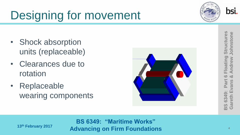
Designing for movement
• Shock absorption
units (replaceable)
• Clearances due to
rotation
• Replaceable
wearing components
4

BS 6349: “Maritime Works”
Advancing on Firm Foundations 13th February 2017
BS
63
49
: P
art
6 F
loa
tin
g S
tru
ctu
res
Ga
reth
Eva
ns
& A
nd
rew
Jo
hn
sto
ne
Design of pontoons – stability
5

BS 6349: “Maritime Works”
Advancing on Firm Foundations 13th February 2017
BS
63
49
: P
art
6 F
loa
tin
g S
tru
ctu
res
Ga
reth
Eva
ns
& A
nd
rew
Jo
hn
sto
ne
Basic ship stability
6
Metacentric height (GM) is a measure of
initial stability. The greater the metacentric
height, the greater is the restoring leaver,
and hence stability.

BS 6349: “Maritime Works”
Advancing on Firm Foundations 13th February 2017
BS
63
49
: P
art
6 F
loa
tin
g S
tru
ctu
res
Ga
reth
Eva
ns
& A
nd
rew
Jo
hn
sto
ne
Righting lever (GZ) curves
7

BS 6349: “Maritime Works”
Advancing on Firm Foundations 13th February 2017
BS
63
49
: P
art
6 F
loa
tin
g S
tru
ctu
res
Ga
reth
Eva
ns
& A
nd
rew
Jo
hn
sto
ne
Effect of free surfaces
8

BS 6349: “Maritime Works”
Advancing on Firm Foundations 13th February 2017
BS
63
49
: P
art
6 F
loa
tin
g S
tru
ctu
res
Ga
reth
Eva
ns
& A
nd
rew
Jo
hn
sto
ne
Applying heeling moments
9

BS 6349: “Maritime Works”
Advancing on Firm Foundations 13th February 2017
BS
63
49
: P
art
6 F
loa
tin
g S
tru
ctu
res
Ga
reth
Eva
ns
& A
nd
rew
Jo
hn
sto
ne
Notes: The six-column grid
IMO criteria for ships:
Area under the curve up to 30o should not be less than 0.55 metre-radians
Area under the curve up to 40o (or angle of downflooding) should not be less than 0.09 metre-radians.
The area between 30o – 40o should not be less than 0,03 metre-radians.
The righting lever GZ should not be less than 0.20m at an angle of 30o or greater.
Maximum righting arm should occur at an angle of heel preferable exceeding 30o, but not less than 25o.
10
BS 6349: “Maritime Works”
Advancing on Firm Foundations 13th February 2017
BS
63
49
: P
art
6 F
loa
tin
g S
tru
ctu
res
Ga
reth
Eva
ns
& A
nd
rew
Jo
hn
sto
ne
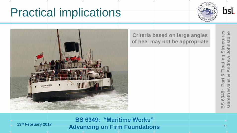
Practical implications
11
Criteria based on large angles
of heel may not be appropriate
BS 6349: “Maritime Works”
Advancing on Firm Foundations 13th February 2017
BS
63
49
: P
art
6 F
loa
tin
g S
tru
ctu
res
Ga
reth
Eva
ns
& A
nd
rew
Jo
hn
sto
ne
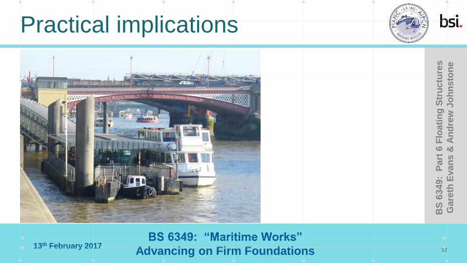
Practical implications
12
BS 6349: “Maritime Works”
Advancing on Firm Foundations 13th February 2017
BS
63
49
: P
art
6 F
loa
tin
g S
tru
ctu
res
Ga
reth
Eva
ns
& A
nd
rew
Jo
hn
sto
ne
Design risk assessment:
• A statement on the intended use.
• The environmental design criteria used, including return periods and limiting
environmental conditions.
• The design loads including any load restrictions and how these are controlled.
• Limiting responses to loads such as minimum freeboard, maximum walkway
gradients, and evacuation criteria.
• Cyclic loading and natural frequency; fatigue of critical elements.
• Suitable stability criteria including the effects of moorings or adjacent pontoons.
13

BS 6349: “Maritime Works”
Advancing on Firm Foundations 13th February 2017
BS
63
49
: P
art
6 F
loa
tin
g S
tru
ctu
res
Ga
reth
Eva
ns
& A
nd
rew
Jo
hn
sto
ne
Practical implications
14

BS 6349: “Maritime Works”
Advancing on Firm Foundations 13th February 2017
BS
63
49
: P
art
6 F
loa
tin
g S
tru
ctu
res
Ga
reth
Eva
ns
& A
nd
rew
Jo
hn
sto
ne
Design risk assessment
• Accidental damage criteria (flooding, collision loads, mooring line failure).
• Inspection and maintenance cycle requirements including the stability case for
delivery and maintenance.
• Environmental impact and pollution containment measures (sewage and fuels).
• Requirements for lifesaving appliances and navigation aids.
• Any ballasting requirements.
15

BS 6349: “Maritime Works”
Advancing on Firm Foundations 13th February 2017
BS
63
49
: P
art
6 F
loa
tin
g S
tru
ctu
res
Ga
reth
Eva
ns
& A
nd
rew
Jo
hn
sto
ne
Marina Pontoons
Typical marina style pontoons consist of a deck, most probably a timber system
on a steel galvanised frame which is supported on a system of floats.
The floats may either be a poly block encased in concrete, a set of plastic ‘boxes’
or perhaps a poly block with a simple GRP covering.
The essence of stability is the Metacentric height which needs to be positive to be
stable. The nearer to 0 the more tender and more ie easily capsizeable the unit.
BS6349 pt 6 did give some guidance on allowable limits, Table 9
Dealing with Pontoons the range given is 1.0m to 15m.
At +15m the unit being very stable
16 February 2017 16
BS 6349: “Maritime Works”
Advancing on Firm Foundations 13th February 2017
BS
63
49
: P
art
6 F
loa
tin
g S
tru
ctu
res
Ga
reth
Eva
ns
& A
nd
rew
Jo
hn
sto
ne
Stability
Analysis of the Metacentric height can be simply ascertained in considering pontoons as opposed to vessels as the waterplane area will remain relatively constant over the heel range that can be expected in service.
The procedure as set out in the existing code will be included in the proposed new version.
In looking at heel and stability the YHA guide specifies a minimum reserve freeboard to the floats of 50mm. This is another area where the new code will seek to provide guidance, however!
As an anecdotal point in relation to a set of pontoons used for a well known on water boat show, the pontoon providers were asked about the design live loads and what would happen if this were exceeded. The answer was ‘the people will start to get wet feet as the pontoons are loaded to a point where the buoyancy of the floats are exceeded at which point people will tend to back away and the pontoon deck will return to its normal freeboard’
In that case the footprint of the pontoon walkways and fingers provided an overall stable platform and with sealed floatation units the loads are spread along the walkways and if some floats are effectively ‘sunk’ they haven't lost their inherent buoyancy. What this does highlight is the need to adequately design and specify the connections between the individual pontoons
17

BS 6349: “Maritime Works”
Advancing on Firm Foundations 13th February 2017
BS
63
49
: P
art
6 F
loa
tin
g S
tru
ctu
res
Ga
reth
Eva
ns
& A
nd
rew
Jo
hn
sto
ne
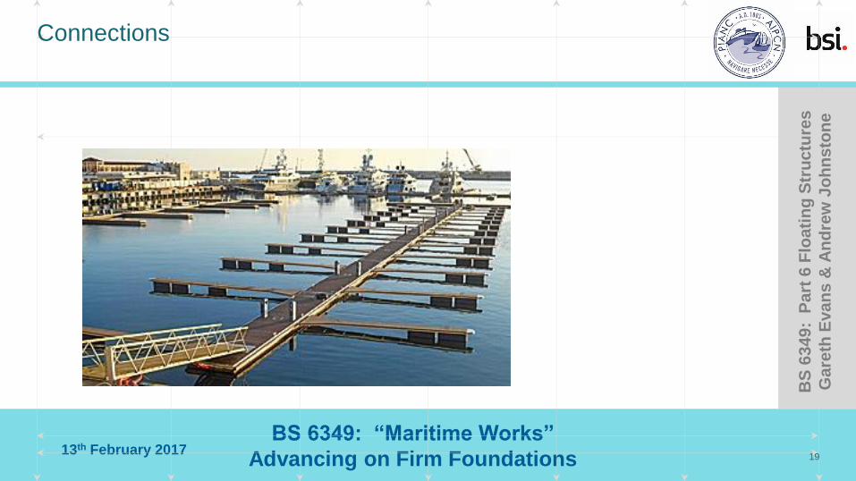
Connections for Pontoons used in the Marina type environment
Pontoons used in the Marina environment often rely on the interconnection between units to provide the stability, utilising the buoyancy of the adjacent floats on either fingers or walkways.
Typical Marina Pontoon Units
This requires the designers to assess the forces that will be transmitted across the joints and the type of joint for the location and exposure.
The joints are under constant stress due to the motion of the units flexing. Often the stability of an single run of walkway pontoons is very tender the MGyy often very small. The effects of either concrete floats or plastic can also have significant effects on the stability of the unit. However stability is not usually an issue once connected to a system of units.
• ’.
Connections
18
BS 6349: “Maritime Works”
Advancing on Firm Foundations 13th February 2017
BS
63
49
: P
art
6 F
loa
tin
g S
tru
ctu
res
Ga
reth
Eva
ns
& A
nd
rew
Jo
hn
sto
ne
Connections
19

BS 6349: “Maritime Works”
Advancing on Firm Foundations 13th February 2017
BS
63
49
: P
art
6 F
loa
tin
g S
tru
ctu
res
Ga
reth
Eva
ns
& A
nd
rew
Jo
hn
sto
ne
Connections
Consideration of the various types of joint are used, for example:-
1. flexible rubber jointed units
20
BS 6349: “Maritime Works”
Advancing on Firm Foundations 13th February 2017
BS
63
49
: P
art
6 F
loa
tin
g S
tru
ctu
res
Ga
reth
Eva
ns
& A
nd
rew
Jo
hn
sto
ne
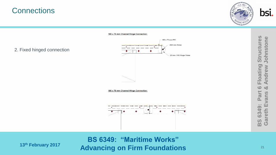
Connections
2. Fixed hinged connection
21

BS 6349: “Maritime Works”
Advancing on Firm Foundations 13th February 2017
BS
63
49
: P
art
6 F
loa
tin
g S
tru
ctu
res
Ga
reth
Eva
ns
& A
nd
rew
Jo
hn
sto
ne
Connections
3. Steel box connection option
22
BS 6349: “Maritime Works”
Advancing on Firm Foundations 13th February 2017
BS
63
49
: P
art
6 F
loa
tin
g S
tru
ctu
res
Ga
reth
Eva
ns
& A
nd
rew
Jo
hn
sto
ne
Connections
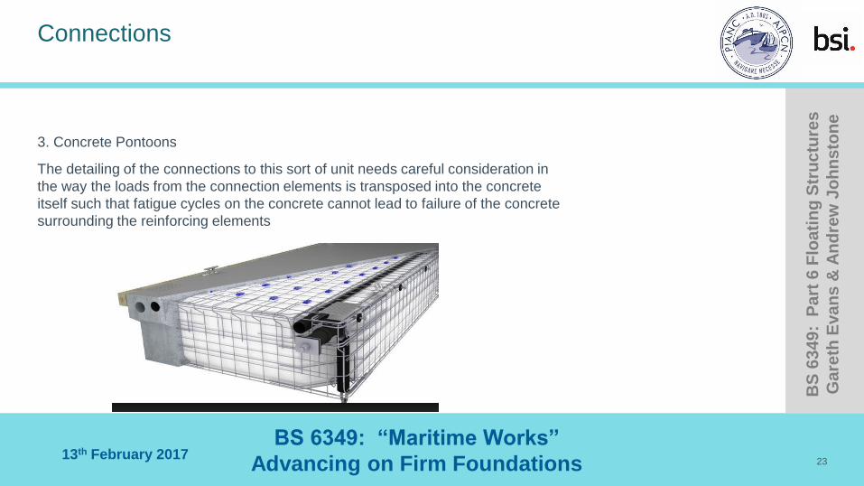
3. Concrete Pontoons
The detailing of the connections to this sort of unit needs careful consideration in
the way the loads from the connection elements is transposed into the concrete
itself such that fatigue cycles on the concrete cannot lead to failure of the concrete
surrounding the reinforcing elements
23

BS 6349: “Maritime Works”
Advancing on Firm Foundations 13th February 2017
BS
63
49
: P
art
6 F
loa
tin
g S
tru
ctu
res
Ga
reth
Eva
ns
& A
nd
rew
Jo
hn
sto
ne
Guides
Mooring of pontoon units
Typical piled installation
Various types of mooring details are available to the designer from:-
1. Piles
2. Anchor and Chain
3. Elastomeric types
4.Wall guides
For types 1 and 4 the motion of the units needs to be considered. If too much heel occurs or the heave / roll response is to great then the pontoon pile guide can put considerable loads on the pile or guide and could cause the system to bind or be damaged.
24

BS 6349: “Maritime Works”
Advancing on Firm Foundations 13th February 2017
BS
63
49
: P
art
6 F
loa
tin
g S
tru
ctu
res
Ga
reth
Eva
ns
& A
nd
rew
Jo
hn
sto
ne
Guides
25
Elastomeric types can be useful in some locations but consideration of water depth / tidal range needs
very careful attention to ensure the angles of moorings always stay reasonably the same and that the
tension variation is within the capacity of the system.

BS 6349: “Maritime Works”
Advancing on Firm Foundations 13th February 2017
BS
63
49
: P
art
6 F
loa
tin
g S
tru
ctu
res
Ga
reth
Eva
ns
& A
nd
rew
Jo
hn
sto
ne
Pontoon Loadings & Stability
The principal factor in safe operation for all concepts on floating structures is stability, ie the ability to withstand overturning forces or moments and return to a normal attitude after removal of the unbalancing loads
Also in respect to loading it is considered reasonable on pontoons with service ducts to look at the applied load over the central section not necessarily the full pontoon width.
A comparison of loads noted from various well respected publications already in existence is shown below:-
26

BS 6349: “Maritime Works”
Advancing on Firm Foundations 13th February 2017
BS
63
49
: P
art
6 F
loa
tin
g S
tru
ctu
res
Ga
reth
Eva
ns
& A
nd
rew
Jo
hn
sto
ne
Loadings
27

BS 6349: “Maritime Works”
Advancing on Firm Foundations 13th February 2017
BS
63
49
: P
art
6 F
loa
tin
g S
tru
ctu
res
Ga
reth
Eva
ns
& A
nd
rew
Jo
hn
sto
ne
Loadings considered for inclusion in new Code
Item Flotation Stability
Un Restricted Access 5 kn/m2 2.5 kn/m2
Restricted Access 2 kn/m2 1.5kn/m2
Marina’s: Secondary walkways 1.5 kn/m2 1.5 kn/m2
Fingers 1kn/m2 1kn/m2
28
For flotation apply over deck plan and for stability over the parts of the deck giving worst load
distribution ie ½ width for heeling, but not under gangways for structural analysis