Part 6 Chap 11 - Public.Resource.Org · · 2017-09-29Part 6 Structural Design ... P1 = Ratio of...
51
Part 6 Structural Design 6‐643 Chapter 11 TIMBER 11.1 SCOPE 11.1.1 This Section relates to the use of structural timber in structures or elements of structures connected together by fasteners/fastening techniques. 11.1.2 This shall not be interpreted to prevent the use of material or methods of design or construction not specifically mentioned herein; and the methods of design may be based on analytical and engineering principles, or reliable test data, or both, that demonstrate the safety and serviceability of the resulting structure. Nor is the classification of timber into strength groups to be interpreted as preventing the use of design data desired for a particular timber or grade of timber on the basis of reliable tests. 11.2 TERMINOLOGY 11.2.1 This section provides an alphabetical list of the terms used in this chapter of the Code. In case of any conflict or contradiction between a definition given in this section and that in Part 1, the meaning provided in this section shall govern for interpretation of the provisions of this chapter. 11.2.2 Structural Purpose Definitions 11.2.2.1 Beam, Built‐Up‐Laminated A beam made by joining layers of timber together with mechanical fastenings, so that the grain of all layers is essentially parallel. 11.2.2.2 Beam, Glued‐Laminated A beam made by bonding layers of veneers or timber with an adhesive, so that grain of all laminations is essentially parallel. 11.2.2.3 Diaphragm, Structural A structural element of large extent placed in a building as a wall, or roof, and made use of to resist horizontal forces such as wind or earthquakes‐acting parallel to its own plane. 11.2.2.4 Duration of Load Period during which a member or a complete structure is stressed as a consequence of the loads applied. 11.2.2.5 Edge Distance The distance measured perpendicular to grain from the centre of the connector to the edge of the member. 11.2.2.6 End Distance The distance measured parallel to grain of the member from the centre of the connector to the closest end of timber. 11.2.2.7 Finger Joint Joint produced by connecting timber members end‐to‐end by cutting profiles (tapered projections) in the form of V‐shaped grooves to the ends of timber planks or scantlings to be joined, gluing the interfaces and then mating the two ends together under pressure.
Transcript of Part 6 Chap 11 - Public.Resource.Org · · 2017-09-29Part 6 Structural Design ... P1 = Ratio of...

Part 6 Structural Design 6‐643
Chapter 11
TIMBER
11.1 SCOPE
11.1.1 This Section relates to the use of structural timber in structures or elements of structures connected together by fasteners/fastening techniques.
11.1.2 This shall not be interpreted to prevent the use of material or methods of design or construction not specifically mentioned herein; and the methods of design may be based on analytical and engineering principles, or reliable test data, or both, that demonstrate the safety and serviceability of the resulting structure. Nor is the classification of timber into strength groups to be interpreted as preventing the use of design data desired for a particular timber or grade of timber on the basis of reliable tests.
11.2 TERMINOLOGY
11.2.1 This section provides an alphabetical list of the terms used in this chapter of the Code. In case of any conflict or contradiction between a definition given in this section and that in Part 1, the meaning provided in this section shall govern for interpretation of the provisions of this chapter.
11.2.2 Structural Purpose Definitions
11.2.2.1 Beam, Built‐Up‐Laminated
A beam made by joining layers of timber together with mechanical fastenings, so that the grain of all layers is essentially parallel.
11.2.2.2 Beam, Glued‐Laminated
A beam made by bonding layers of veneers or timber with an adhesive, so that grain of all laminations is essentially parallel.
11.2.2.3 Diaphragm, Structural
A structural element of large extent placed in a building as a wall, or roof, and made use of to resist horizontal forces such as wind or earthquakes‐acting parallel to its own plane.
11.2.2.4 Duration of Load
Period during which a member or a complete structure is stressed as a consequence of the loads applied.
11.2.2.5 Edge Distance
The distance measured perpendicular to grain from the centre of the connector to the edge of the member.
11.2.2.6 End Distance
The distance measured parallel to grain of the member from the centre of the connector to the closest end of timber.
11.2.2.7 Finger Joint
Joint produced by connecting timber members end‐to‐end by cutting profiles (tapered projections) in the form of V‐shaped grooves to the ends of timber planks or scantlings to be joined, gluing the interfaces and then mating the two ends together under pressure.

Part 6 Structural Design
6‐644 Vol. 2
11.2.2.8 Fundamental or Ultimate Stress
The stress which is determined on small clear specimen of timber, in accordance with good practice; and does not take into account the effect of naturally occurring characteristics and other factors.
11.2.2.9 Inside Location
Position in buildings in which timber remains continuously dry or protected from weather.
11.2.2.10 Laminated Veneer Lumber
A structural composite made by laminating veneers, 1.5 mm to 4.2 mm thick, with suitable adhesive and with the grain of veneers in successive layers aligned along the longitudinal (length) dimension of the composite.
11.2.2.11 Loaded Edge Distance
The distance measured from the centre to the edge towards which the load induced by the connector acts, and the unloaded edge distance is the one opposite to the loaded edge.
11.2.2.12 Location
A term generally referred to as exact place where a timber is used in building.
11.2.2.13 Outside Location
Position in buildings in which timbers are occasionally subjected to wetting and drying as in the case of open sheds and outdoor exposed structures.
11.2.2.14 Permissible Stress
Stress obtained by applying factor of safety to the ultimate stress.
11.2.2.15 Sandwich, Structural
A layered construction comprising a combination or relatively high‐strength facing material intimately bonded to and acting integrally with a low density core material.
11.2.2.16 Spaced Column
Two column sections adequately connected together by glue, bolts, screws or otherwise.
11.2.2.17 Structure, Permanent
Structural units in timber which are constructed for a long duration and wherein adequate protection and design measures have initially been incorporated to render the structure serviceable for the required life.
11.2.2.18 Structure, Temporary
Structures which are erected for a short period, such as hutments at project sites, for rehabilitation, temporary defence constructions, exhibition structures, etc.
11.2.2.19 Structural Element
The component timber members and joints which make up a resulting structural assembly.
11.2.2.20 Structural Grades
Grades defining the maximum size of strength reducing natural characteristics (knots, sloping grain, etc) deemed permissible in any piece of structural timber within designated structural grade classification.
11.2.2.21 Structural Timber
Timber in which strength is related to the anticipated in‐service use as a controlling factor in grading and selection and/or stiffness.
11.2.2.22 Termite
An insect of the order Isopteran which may burrow in the wood or wood products of a building for food or shelter.

Timber Chapter 11
Bangladesh National Building Code 2011 6‐645
11.2.2.23 Wet Location
Position in buildings in which timbers are almost continuously damp or wet in contact with the earth or water, such as piles and timber foundations.
11.2.3 Definitions of Defects in Timber
11.2.3.1 Check
A separation of fibres extending along the grain which is confined to one face of a piece of wood.
11.2.3.2 Compression Wood
Abnormal wood which is formed on the lower sides of branches and inclined stems of coniferous trees. It is darker and harder than normal wood but relatively low in strength for its weight. It can be usually identified by wide eccentric growth rings with abnormally high proportion of growth latewood.
11.2.3.3 Dead Knot
A knot in which the layers of annual growth are not completely intergrown with those of the adjacent wood. It is surrounded by pitch or bark. The encasement may be partial or complete.
11.2.3.4 Decay or Rot
Disintegration of wood tissue caused by fungi (wood destroying) or other microorganisms.
11.2.3.5 Decayed Knot
A knot softer than the surrounding wood and containing decay.
11.2.3.6 Diameter of Knot
The maximum distance between the two points farthest apart on the periphery of a round knot, on the face on which it becomes visible. In the case of a spike or a splay knot, the maximum width of the knot visible on the face on which it appears shall be taken as its diameter.
11.2.3.7 Discoloration
A change from the normal colour of the wood which does not impair the strength of the wood.
11.2.3.8 Knot
A branch base or limb embedded in the tree or timber by natural growth.
11.2.3.9 Knot Hole
A hole left as a result of the removal of a knot.
11.2.3.10 Live Knot
A knot free from decay and other defects, in which the fibres are firmly intergrown with those of the surrounding wood. Syn. ‘Integrown knot’; cf. ‘Dead Knot’.
11.2.3.11 Loose Grain (Loosened Grain)
A defect on a 6 flat sawn surface caused by the separation or raising of wood fibres along the growth rings; C$ ‘Raised Grain’.
11.2.3.12 Loose Knot
A knot that is not held firmly in place by growth or position, and that cannot be relied upon to remain in place; cf ‘Tight Knot’.
11.2.3.13 Mould
A soft vegetative growth that forms on wood in damp, stagnant atmosphere. It is the least harmful type of fungus, usually confined to the surface of the wood.

Part 6 Structural Design
6‐646 Vol. 2
11.2.3.14 Pitch Pocket
Accumulation of resin between growth rings of coniferous wood as seen on the cross section.
11.2.3.15 Sap Stain
Discoloration of the sapwood mainly due to fungi.
11.2.3.16 Sapwood
The outer layer of log, which in the growing tree contain living cells and food material. The sapwood is usually lighter in colour and is readily attacked by insects and fungi.
11.2.3.17 Shake
A partial or complete separation between adjoining layers of tissues as seen in end surfaces.
11.2.3.18 Slope of Grain
The inclination of the fibres to the longitudinal axis of the member.
11.2.3.19 Sound Knot
A tight knot free from decay, which is solid across its face, and at least as hard as the surrounding wood.
11.2.3.20 Split
A crack extending from one face of a piece of wood to another and mns along the grain of the piece.
11.2.3.21 Tight Knot
A knot so held by growth or position as to remain firm in position in the piece of wood; C$ ‘Loose Knot’.
11.2.3.22 Wane
The original rounded surface of a tree remaining on a piece of converted timber.
11.2.3.23 Warp
A deviation in sawn timber from a true plane surface or distortion due to stresses causing departure from a true plane.
11.2.3.24 Warm Holes
Cavities caused by worms.
11.3 SYMBOLS
11.3.1 For the purpose of this Section, the following letter symbols shall have the meaning indicated against each:
a= Projected area of bolt in main member (t’ X d3), mm2
B= Width of the beam, mm
C= Concentrated load, N
D= Depth of beam, mm
D1 = Depth of beam at the notch, mm
D2 = Depth of notch, mm
d= Dimension of least side of column, mm
d1 = Least overall width of box column, mm
d2 = Least overall dimension of core in box column, mm
d3 = Diameter of bolt, mm
df = Bolt‐diameter factor

Timber Chapter 11
Bangladesh National Building Code 2011 6‐647
e= Length of the notch measured along the beam span from the inner edge of the support to the farthest edge of the notch, mm
E= Modulus of elasticity in bending, N/mm2
F= Load acting on a bolt at an angle to grain, N
fab = Calculated bending stress in extreme fibre, N/mm2
fac = Calculated average axial compressive stress, N/mm2
fat = Calculated axial tensile stress, N/mm2
fb = Permissible bending stress on the extreme fibre, N/mm2
fc= Permissible stress in axial compression, N/mm2
fcn = Permissible stress in compression normal (perpendicular) to grain, N/mm2
fcp = Permissible stress in compression parallel to grain, N/mm2
fcθ=Permissible compre~sive stress in the direction of the line of action of the load, N/mm2
ft = Permissible stress in tension parallel to grain, N/mm2
H= Horizontal shear stress, N/mm2
I= Moment of inertia of a section, mm4
K= Coefficient in deflection depending upon type and criticality of loading on beam
K1 = Modification factor for change in slope of grain
K2 = Modification factor for change in duration of loadings
=
⎪⎪⎪
⎭
⎪⎪⎪
⎬
⎫
6
,5
,4
,3
KandKKK
Form factors
K7 = Modification factor for bearing stress
K8 = Constant equal to cpfE584.0
K9 = Constant equal to cpqf
UE52
π
K10= Constant equal to cpfE5.2584.0
L= Span of a beam or truss, mm
M= Maximum bending moment in beam N/mm2
N= Total number of bolts in the joint
n= Shank diameter of the nail, mm
P= Load on bolt parallel to grain, N
P1 = Ratio of the thickness of the compression flange to the depth of the beam
Q = Statical moment of area above or below the neutral axis about neutral axis, mm3
q = Constant for particular thickness of plank
q1 = Ratio of the total thickness of web or webs to the overall width of the beam
R= Load on bolt perpendicular (normal) to grain, N
S= Unsupported overall length of column, mm
t = Nominal thickness of planks used in forming box type column, mm

Part 6 Structural Design
6‐648 Vol. 2
t’ = Thickness of main member, mm
U= Constant for a particular thickness of the plank
V= Vertical end reaction or shear at a section, N
W = Total uniform load, N
x = Distance from reaction to load, mm
γ = A factor determining the value of form factor K4
δ= Deflection at middle of beam, mm
θ = Angle of load to grain direction Z= Section modulus of beam, mm3
λ1 = Percentage factor for t’/d3 ratio, parallel to grain λ2 = Percentage factor for t’/d3 ratio, perpendicular to grain
11.4 MATERIALS
11.4.1 Species of Timber
The species of timber recommended for structural purposes are given in Table 11.4.1.
11.4.1.1 Grouping
Species of timber recommended for constructional purposes are classified in three groups on the basis of their strength properties, namely, modulus of elasticity (E) and extreme fibre stress in bending and tension (fb).
The characteristics of these groups areas given below:
Group A — E above 12.6 x 10³ N/mm2 and fb above 18.0 N/mm2.
Group B — E above 9.8 x 10³ N/mm2 and up to 12.6 x 10³ N/mm2 and fb above 12.0 N/mm2 and up to 18.0 N/mm2.
Group C — E above 5.6 x 10³ N/mm2 and up to 9.8 x 10³ N/mm2 and fb above 8.5 N/mm2 and up to 12.0 N/mm2.
NOTE — Modulus of elasticity given above is applicable for all locations and extreme fibre stress in bending is for inside location.
11.4.2
The general characteristics like durability and treat ability of the species are also given in Table 11.4.1.
Species of timber other than those recommended in Table 11.4.1 may be used, provided the basic strength properties are determined and found in accordance with 11.5.1.
NOTE — For obtaining basic stress figures of the unlisted species, reference may be made to the Forest Research Institute, Debra Dun.
11.4.3
The permissible lateral strength (in double shear) of mild steel wire shall be as given in Table 11.4.2 and Table 11.4.3 for different species of timber.
11.4.4
Moisture Content in Timber The permissible moisture content of timber for various positions in buildings shall be as given in Table 11.4.4.

Timber Chapter 11
Bangladesh National Building Code 2011 6‐649
Table 11.4.1 Safe Permissible Stresses for the Species of Timber
Species Average
Density at 12
percent
Content
Kg/m3
Modulus of
Elasticity x
103 N/mm2
Permissible Stress in N/mm2 for Grade I Preservative Characters
Botanical Name Trade
Name
Bending and
Tension Along
Grains, Extreme
Fibre Stress
Shear all
Location
Compression
Parallel to Grain
Compression
Perpendicular to
Grain
Durability
Class
Treatability
Grade
Refracterines to
All Seasoning
Inside
Location
outside Location
wet Location
Horizon
tal
Along
Grain
Inside
Location
outside Location
wet Location
Inside
Location
outside Location
wet Location
1 2 3 4 5 6 7 8 9 10 11 12 13 14 15 16 17 18
Acacia nilotica Babla 797 _ _ 12.9 10.3 1.4 2.1 8.9 7.9 6.4 5.2 4.0 3.3 I b B
Aglaia odulis Aglaia 815 12.56 18.2 15.2 12.1 1.4 2.0 10.1 8.9 7.3 4.4 3.4 2.8 _ _ A
Ailantahus grandis Gokul 404 7.94 8.3 6.9 5.5 0.6 0.8 5.3 4.7 3.9 1.1 0.9 0.7 III _ C
Altingia excelsa
Jutili 795 11.37 17.1 14.3 11.4 1.2 1.8 11.0 9.8 8.0 6.8 5.3 4.4 II e A
Amoora rehituka
Pitraj 668 8.98 12.3 10.2 8.2 1.1 1.5 8.0 7.1 5.8 4.0 3.1 2.6 I _ B
Amoora wallichii Lali 583 _ _ _ _ _ _ _ _ _ _ _ _ _ _ _
Amoora spp. Arnari 625 1.05 13.4 1.1 9.2 0.9 1.3 8.4 7.4 6.0 3.7 2.9 2.4 II d B
Anisoplera glabra Boilam 573 _ _ _ _ _ _ _ _ _ _ _ _ III b _
Aphenamixis polystachya Pitraj 583 _ _ _ _ _ _ _ _ _ _ _ _ III e B
Arlocarpus chaplasha Chapalish 515 9.11 13.2 11.0 8.8 0.9 1.2 8.5 7.5 6.2 3.6 2.8 2.3 III d B
Artocarpus integrifolia Kanthal 537 _ _ _ _ _ _ _ _ _ _ _ _ III c B
Azadirachta indica Neem 836 8.52 14.6 12.1 9.7 1.3 1.8 10.0 8.9 7.3 5.0 3.9 3.2 _ _ _
Betula lnoides Birch 625 9.23 9.6 8.0 6.4 0.8 1.1 5.7 5.0 4.1 2.2 1.7 1.4 _ _ B
Bischofia javanica Bhadi 769 8.84 9.6 8.2 6.5 0.8 1.1 5.9 5.3 4.3 3.6 2.8 2.3 III _ A
Bruguiera conjugata Kankra 879 _ _ _ _ _ _ _ _ _ _ _ _ _ _ A

Part 6 Structural Design
6‐650 Vol. 2
Species Average
Density at 12
percent
Content
Kg/m3
Modulus of
Elasticity x
103 N/mm2
Permissible Stress in N/mm2 for Grade I Preservative Characters
Botanical Name Trade
Name
Bending and
Tension Along
Grains, Extreme
Fibre Stress
Shear all
Location
Compression
Parallel to Grain
Compression
Perpendicular to
Grain
Durability
Class
Treatability
Grade
Refracterines to
All Seasoning
Inside
Location
outside Location
wet Location
Horizon
tal
Along
Grain
Inside
Location
outside Location
wet Location
Inside
Location
outside Location
wet Location
1 2 3 4 5 6 7 8 9 10 11 12 13 14 15 16 17 18
Bucklandia populnea Plpli 672 9.89 12.8 10.7 8.6 1.1 1.5 7.9 7.0 5.7 3.5 2.7 2.2 III e C
Canarium strictum White dhup 569 10.54 10.1 8.4 6.7 0.7 1.1 6.2 5.5 4.5 2.1 1.6 1.3 III _ C
Cassia fistula Sonalu 865 11.80 19.2 16.0 12.8 1.4 2.0 12.3 10.9 8.9 7.2 5.6 4.6 I _ A
Castanopsis hystrix Chestanut 624 9.85 10.6 8.8 7.0 0.8 1.2 6.4 5.7 4.6 2.7 2.1 1.7 II b B
Carallia lucida Maniawaga 748 12.60 18.4 15.3 12.3 1.2 1.7 11.4 10.1 8.3 5.9 4.6 3.8 _ _ _
Cassia siamea Minjiri 695 _ _ _ _ _ _ _ _ _ _ _ _ _ _ _
Chukrasia tabularis Chickrassy 666 8.35 11.8 9.8 7.9 1.1 1.5 7.1 6.3 5.2 3.9 3.1 2.5 II c B
Dalbergia sissoo Sissoo 808 _ _ _ _ _ _ _ _ _ _ _ _ _ _ B
Dillemia indica Dillenia 617 8.61 12.1 10.0 8.0 0.8 1.2 7.3 6.5 5.3 2.7 2.1 1.7 III a B
Dillenia pentagyne Dillenia 622 7.56 11.8 9.9 7.9 0.9 1.3 7.1 6.3 5.2 3.5 2.7 2.2 III d B
Dipterocarpus alatus Garjan 721 _ _ _ _ _ _ _ _ _ _ _ _ III a B
Dipterocarpus rnacrocarpus Hollong
726 13.34 14.5 12.0 9.6 0.8 1.1 8.8 7.9 6.4 3.5 2.7 2.2 III a B
Duabanga sonneratioides Banderhol 485 8.38 9.8 8.2 6.5 0.6 0.9 6.4 5.7 4.7 1.8 1.4 1.1 III c C
Garuga piannata Garuga 571 7.58 11.7 9.7 7.8 1.0 1.5 7.2 6.4 5.3 3.4 2.6 2.1 I e B
Geriops roxbarghiana Goran 869 _ _ _ _ _ _ _ _ _ _ _ _ _ _ _
gGmeline arborea Garnar 501 7.02 9.8 8.2 6.6 0.8 1.4 5.7 5.0 4.1 4.2 3.2 2.7 I e B
Grewia veslita Dhaman 758 12.00 15.4 12.6 10.3 1.4 2.0 9.1 8.1 6.6 4.1 3.2 2.6 III d B
Heritiera spp. Sundri 872 13.37 17.9 14.9 11.9 1.3 1.8 11.0 9.8 8.0 6.5 5.0 4.1 I _ A

Timber Chapter 11
Bangladesh National Building Code 2011 6‐651
Species Average
Density at 12
percent
Content
Kg/m3
Modulus of
Elasticity x
103 N/mm2
Permissible Stress in N/mm2 for Grade I Preservative Characters
Botanical Name Trade
Name
Bending and
Tension Along
Grains, Extreme
Fibre Stress
Shear all
Location
Compression
Parallel to Grain
Compression
Perpendicular to
Grain
Durability
Class
Treatability
Grade
Refracterines to
All Seasoning
Inside
Location
outside Location
wet Location
Horizon
tal
Along
Grain
Inside
Location
outside Location
wet Location
Inside
Location
outside Location
wet Location
1 2 3 4 5 6 7 8 9 10 11 12 13 14 15 16 17 18
Hopea odorata Telsur 711 _ _ _ _ _ _ _ _ _ _ _ _ III a B
Kayea floribund Karal 813 10.88 16.8 14.0 1.1 1.1 1.6 10.1 9.0 7.3 4.4 3.4 2.8 III _ _
Lagerstrocmia spp. Jarul 654 _ _ _ _ _ _ _ _ _ _ _ _ III e B
Machilus macrantha Machilus 692 10.00 12.4 10.3 8.3 1.0 1.5 8.2 7.3 6.0 3.5 2.7 2.2 III e B/C
Manglietia insignia 449 10.37 10.9 9.1 7.3 0.7 1.4 8.0 7.1 5.8 3.4 2.6 2.1 _ _ _
Manilota polyandra Ping 903 13.20 19.1 15.9 12.7 1.3 1.8 1.2 10.0 8.5 5.7 4.4 3.6 III b A
Mesua assamica Keyea 842 12.83 17.4 14.5 11.6 1.0 1.4 11.7 10.4 8.5 5.3 4.1 3.3 II e _
Mesua ferrea Mesua 965 16.30 23.3 19.4 15.5 1.2 1.8 15.5 13.8 11.3 5.9 4.6 3.7 I _ A
Michelia champaca Champa 644 _ _ _ _ _ _ _ _ _ _ _ _ _ _ B
Michelia montana Champ 512 8.25 10.9 9.1 7.3 0.7 1.0 6.6 5.9 4.8 2.8 2.2 1.8 I _ B
Michelia excelsa Champ
513 10.12 9.8 8.2 6.5 0.7 1.0 6.1 5.5 4.5 1.6 1.3 1.0 II e B
Mitragyna pervifolia Dakroom 651 7.82 12.6 10.5 8.4 1.0 1.5 7.9 7.0 5.7 3.7 2.9 2.4 III b B
Palaquium polyanthum Tali 734 11.24 14.9 12.4 10.0 1.1 1.6 9.9 8.8 7.2 4.7 3.7 3.0 _ _ B
Phoebe hainesiana Bonsum 566 9.5 13.2 11.0 8.8 0.8 1.2 8.8 7.8 6.4 2.8 2.1 1.8 II c B
Phoebe goalperansis Bonsum 511 7.65 9.7 8.1 6.5 0.7 1.0 6.6 5.9 4.8 2.2 1.7 1.4 II c B
Plerygota alata Narikel 593 10.95 13.4 11.8 8.9 0.8 1.2 8.2 7.3 6.0 2.7 2.1 1.7 III _ C
Prunus napeulensis Arupati 548 9.41 4.4 8.7 69.6 0.9 1.2 6.7 6.0 4.9 2.4 1.9 1.6 _ _ _
Pterespermum acerifolium Hattipaila 607 9.55 13.5 11.3 9.0 0.9 1.2 8.7 7.7 6.3 3.2 2.5 2.0 III C B

Part 6 Structural Design
6‐652 Vol. 2
Species Average
Density at 12
percent
Content
Kg/m3
Modulus of
Elasticity x
103 N/mm2
Permissible Stress in N/mm2 for Grade I Preservative Characters
Botanical Name Trade
Name
Bending and
Tension Along
Grains, Extreme
Fibre Stress
Shear all
Location
Compression
Parallel to Grain
Compression
Perpendicular to
Grain
Durability
Class
Treatability
Grade
Refracterines to
All Seasoning
Inside
Location
outside Location
wet Location
Horizon
tal
Along
Grain
Inside
Location
outside Location
wet Location
Inside
Location
outside Location
wet Location
1 2 3 4 5 6 7 8 9 10 11 12 13 14 15 16 17 18
Quercus lineate Oak 874 12.63 15.2 12.7 10.1 1.2 1.7 9.6 8.6 7.0 5.3 4.1 3.4 II c A
Quercus lamellosa Oak 87 12.44 14.5 12.1 9.7 1.2 1.7 8.7 7.8 6.4 3.8 2.9 2.4 II c A
Schima wallichii Chilauni 693 9.57 11.1 9.3 7.4 0.9 1.3 6.6 5.9 4.8 2.3 1.8 1.4 III d B
Seritiera fomes Sundri 1073 _ _ _ _ _ _ _ _ _ _ _ _ III b B
Shotea assamica Makai 548 9.27 11.1 9.2 7.4 0.9 1.3 7.1 6.3 5.2 2.9 2.2 1.8 III c B
Shorea robusta Sal 889 _ _ _ _ _ _ _ _ _ _ _ _ III e B
Sonneralia apetale Keora 617 8.63 12.8 10.7 8.5 0.9 1.3 7.4 6.6 5.4 4.8 3.7 3.0 II _ B
Swintonia floribunda Civit 665 _ _ _ _ _ _ _ _ _ _ _ _ III a C
Syzygium cumini Jamun 841 10.55 14.8 12.4 9.9 1.1 1.6 9.0 8.0 6.5 6.9 5.4 4.4 II e A
Syzygium spp. Jam 823 _ _ _ _ _ _ _ _ _ _ _ _ III e A
Taxus buccata Yew 705 7.79 14.3 11.9 9.5 1.2 1.7 8.7 7.8 6.4 4.7 3.7 3.0 _ _ _
Tectona grandis Teak 660 9.97 15.5 12.9 10.3 1.2 1.6 9.4 8.3 6.8 4.5 3.5 2.8 I e B
Toena ciliata Toon 487 6.40 8.7 7.3 5.8 0.7 1.0 5.4 4.8 3.9 2.4 1.8 1.5 II c B
Terminalia citrna 755 11.89 17.1 14.3 11.4 1.1 1.6 10.8 9.6 7.9 5.0 3.9 3.2 _ _ _
Terminalia myriocarpa Hollock 615 9.62 11.9 9.9 8.0 0.9 1.2 7.6 6.7 5.5 2.9 2.2 1.8 III a B
Xylia dolabriformis Lohakat 1007 _ _ _ _ _ _ _ _ _ _ _ _ _ _ _
Xylocarpus rolloensis Passur 757 _ _ _ _ _ _ _ _ _ _ _ _ _ _ B
Zanthoxylum budranga Mullilam
587 10.65 14.7 12.2 9.8 0.9 1.2 9.5 8.4 6.9 3.4 2.6 2.1 I e B

Timber Chapter 11
Bangladesh National Building Code 2011 6‐653
† Classification for preservation based on durability tests, etc.
Class
I – Average life more than 120 months;
II – Average life 60 months or above but less than 120 months; and
III – Average life less than 60 months.
‡ Treatability Grades
a – Heartwood easily treatable;
b – Heartwood treatable, but complete penetration not always obtained; in case where the least dimension is more than 60 mm;
c – Heartwood only partially treatable;
d – Heartwood refractory to treatment; and
e – Heartwood very refractory to treatment, penetration of preservative being practically nil even from the ends.
Data based on strength properties at three years of age of tree. § Classifications based on seasoning behavior of timber and refractoriness w.r.t. cracking , splitting and drying rate. A – Highly refractory (slow and difficulty to season free from surface and end cracking); B – Moderately refractory (may be seasoned free from surface and end cracking within reasonably short periods, given a little protection against rapid drying conditions); and C – Non‐refractory (may be rapidly seasoned free from surface and end‐cracking even in the open air and sun. If not rapidly dried, they develop blue stain and mould on the surface.

Part 6 Structural Design 6‐654
Table 11.4.2 Permissible Lateral Strengths (in Double Shear) of Nails 3.55 mm Dia, 80 mm Long
Sl
No.
Species of Wood For Permanent Construction
Strength per Nail
For Temporary
Structures Strength
per Nail (for Both
Lengthening Joints and
Node Joints) Nx102
Botanical Name
Trade name
Lengthening
Joints
Nx102
Node Joints
Nx102
1 2 3 4 5 6
Acacia nilotica Babla 15 11 34
Aphenamixis polystachya Pitraj 19 9 19
Canarium strictum White dhup 9 8 10.5
Castanopsis hystrix Chestanut 18 10.5 23.5
Chukrasia tabularis Chickrassy 24 8 27
Dillenia pentagyne Dillenia 16.5 12 16
Dipterocarpus rnacrocarpus Hollong 17 7 20
Grewia veslita Dhaman 13 5 24
Hopea odorata Telsur 31.5 13 28.5
Lagerstrocmia spp. Jarul 24.5 21.5 22.5
Maniltoa polyandra Ping 26 23.5 32
Mesua ferrea Mesua 26 8 41
Michelia excelsa Champ 13 9 20
Phoebe hainesiana Bonsum 12 6 13
Shorea robusta Sal 23 15.5 19.5
Syzygium spp. Jam 15 12 25
Tectona grandis Teak 14 8 13
Terminalia myriocarpa Hollock 13 10 19
Toona ciliata Toon 16 9 21
NOTES 1. Nails of 3.55 mm diameter are most commonly used. The above values can also be used for 4 mm diameter 100 mm long
nails. 2. The values in N are approximate converted values from kgf. For exact conversion the value is 1 kgf = 9.80665 N.
11.4.4.1 Tolerances
Permissible tolerances in measurements of cut sizes of structural timber shall be as follows:
a) For width and thickness:
1) Up to and including 100 mm 03
−+
mm
2) Above 100 mm 36
−+
mm
b) For length 010
−+
mm

Timber Chapter 11
Bangladesh National Building Code 2011 6‐655
11.4.5 Grading of Structural Timber
11.4.5.1 Cut sizes of structural timber shall be graded, after seasoning, into three grades based on permissible defects given in Table 11.4.8:
a) Select Grade b) Grade I c) Grade II
Table 11.4.3 Permissible Lateral Strengths (in Double Shear) of Nails 5.00 mm Dia,125 mm and 150 mm Long
Species of Wood For Permanent Construction
Strength per Nail
For Temporary Structures
Strength per Nail (for
Both Lengthening Joints
and Node Joints) Nx102
Botanical Name Trade name Lengthening
Joints
Nx102
Node
Joints
Nx102
2 3 4 5 6
Acacia nilotica Babla 27 13.5 53
Dalbergia sissoo Sissoo 17 15 43
Mesua ferrea Mesua 24 15.5 57.5
Michelia excelsa Champ 26 12.5 39
Phoebe hainesiana Bonsum 20 7.5 30
Shorea robusta Sal 19.5 17 37
Syzygium spp. Jam 18 14.5 38.5
Tectona grandis Teak 28 13 30
Terminalia myriocarpa Hollock 27.5 9 41
Table 11.4.4 Permissible Percentage Moisture Content Values
Sl
No.
Use Zones (see Note)
(1) (2) (3) (4) (5) (6)
i) Structural elements 12 14 17 20
ii) Doors and windows
50 mm and above in thickness
Thinner than 50 mm
10
8
12
10
14
12
16
14
iii) Flooring strips for general purposes 8 10 10 12
NOTE — The country has been broadly divided into the following four zones based on the humidity variations in the country:
Zone I — Average annual relative humidity less than 40 percent.
Zone II — Average annual relative humidity 40 to 50 percent.
Zone III — Average annual relative humidity 50 to 67 percent.
Zone IV — Average annual relative humidity more than 67 percent.
For detailed zonal classification, tolerances, etc reference may be made to good practice [6‐3A(4)].

Part 6 Structural Design
6‐656 Vol. 2
11.4.6 Sawn Timber
11.4.6.1 Sizes
Preferred cut sizes of timber for use in structural components shall be as given in Tables 11.4.5 to 11.4.7.
Table 11.4.5 Preferred Cut Sizes of Structural Timbers for Roof Trusses (Span from 3 m to 20 m)
Thickness
mm
Width
mm
1 2 3 4 5 6 7 8 9
20 40 50 60 80 100 _ _ _
25 40 50 60 80 100 120 160 180
30 40 50 60 80 100 120 160 180
35 _ _ 60 80 100 120 160 180
40 _ _ 60 80 100 120 160 180
50 _ _ 60 80 100 120 160 180
60 _ _ _ 80 100 120 160 180
80 _ _ _ _ 100 120 160 180
NOTES
1 For truss spans marginally above 20 m, preferred cut sizes of structural timber may be allowed.
2 Preferred lengths of timhec 1, 1.5,2,2.5 and 3 m.
Table 11.4.6 Preferred Cut Sizes of Structural Timber for Roof Purlins, Rafters, Floor Beams, Etc
Thickness
mm
Width
mm
1 2 3 4 5 6 7 8
50 80 100 120 140 _ _ _
60 80 100 120 140 160 _ _
80 _ 100 120 140 160 _ _
100 _ _ _ 140 160 180 200
NOTE —Preferred lengths of timber: 1.5,2,2.5 and 3 m.
Table 11.4.7 Preferred Cut Sizes of Structural Timbers for Partition Framing and Covering, and for Centering
Thickness
mm
Width
mm
1 2 3 4 5 6 7 8 9 10
10 40 50 60 80 _ _ _ _ _
15 40 50 60 80 100 _ _ _ _
20 40 50 60 80 100 120 160 200 _
25 40 50 60 80 100 120 160 200 240
30 40 50 60 80 100 120 160 200 240
40 40 _ 60 80 100 120 160 200 240
50 _ 50 _ 80 100 120 160 200 240
60 _ _ 60 80 100 120 160 200 240
80 _ _ _ 80 100 120 160 200 240

Timber Chapter 11
Bangladesh National Building Code 2011 6‐657
Table 11.4.8 Permissible Defects for Cut Sizes of Timber for Structural Use
Sl
No.
Defects Select Grade Grade I
Grade II
1 2 3 4 5
i) Wane
Shall be permissible at its deepest
portion up to a limit of 1/8 of the
width of the surface on which it
occurs
Shall be permissible at its deepest
portion up to a limit of 1/6 of the
width of the surface on which it
occurs
Shall be permissible at its
deepest
portion up to a limit of 1/4 of
the
width of the surface on
which it
occurs
ii) Worm holes
Other than those due to powder
post beetles are permissible
Other than those due to powder
post beetles are permissible
Other than those due to
powder post
beetles are permissible
iii) Slope of grain
Shall not be more than 1 in 20
Shall not be more than 1 in 15
Shall not be more than 1 in
12
iv) Live knots:
Width of Wide
Faces of Cut
Sizes
of Timber
Permissible Maximum Size of Live
Knot on
Permissible Maximum Size of
Live Knot on
Permissible Maximum Size
of Live Knot on
Max Narrow faces
and
1/4 of the
width
face close to
edges of cut
size
of timber
Remaining
central half of
the width of the
wide faces
Narrow faces
and
1/4 of the
width
face close to
edges of cut
size
of timber
Remaining
central half of
the width of the
wide faces
Narrow
faces and
1A of the
width
face close
to
edges of cut
size
of timber
Remaining
central
half of the
width
of the wide
faces
1 2 3 4 5 6 7
75
100
150
200
250
300
350
400
450
500
550
600
10
13
19
22
25
27
29
32
33
35
36
38
10
13
19
25
29
38
41
44
47
50
52
53
19
25
38
44
50
54
57
63
66
69
72
75
19
25
38
50
57
75
81
87
93
100
103
106
29
38
57
66
66
81
87
96
99
105
108
114
30
39
57
75
87
114
123
132
141
150
156
159
v) Checks and
shakes:

Part 6 Structural Design
6‐658 Vol. 2
Width of the
Face of
the Timber
Max
Permissible Depth
Max
Permissible Depth
Max
Permissible Depth
Max
1 2 3 4
75
100
150
200
250
300
350
400
450
500
550
600
12
18
25
33
40
50
57
66
76
83
90
100
25
35
50
65
81
100
115
131
150
165
181
200
36
54
75
99
120
150
171
198
225
249
270
300
11.4.6.2 The prohibited defects given in 4.6.2.1 and permissible defects given in 4.6.2.2 shall apply to structural timber.
11.4.6.2.1 Prohibited defects
Loose grains, splits, compression wood in coniferous species, heartwood rot, sap rot, crookedness, worm holes made by powder post beetles and pitch pockets shall not be permitted in all the three grades.
11.4.6.2.2 Defects to the extent specified in Table 11.4.8 shall be permissible.
NOTE — Wanes are permitted provided they are not combined with knots and the reduction in strength on account of the wanes is not more than the reduction with maximum allowable knots.
11.4.6.3 Location of Defects
The influence of defects in timber is different for different locations in the structural element. Therefore, these should be placed during construction in such a way so that they do not have any adverse effect on the members.
11.4.7 Suitability
11.4.7.1 Suitability in Respect of Durability and Treatability for Permanent Structures
There are two choices as given in 11.4.7.1.1 and 11.4.7.1.2.
11.4.7.1.1 First choice
The species shall be any one of the following:
a) Untreated heartwood of high durability. Heartwood if containing more than 15 percent sap wood, may need chemical treatment for protection;
b) Treated heartwood of moderate and low durability and class ‘a’ and class ‘b’ treatability; c) Heartwood of moderate durability and class ‘c’ treatability after pressure impregnation, and d) Sapwood of all classes of durability after thorough treatment with preservative.
11.4.7.1.2 Second choice
The species of timber shall be heartwood of moderate durability and class ‘d’ treatability.
11.4.7.2 Choice of load‐beting temporary structures or semi‐structural components at construction site
a) Heartwood of low durability and class ‘e’ treatability; or

Timber Chapter 11
Bangladesh National Building Code 2011 6‐659
b) The species whose durability and/or treatability are yet to be established, as listed in Table 11.4.1.
11.4.8 Fastenings
All structural members shall be framed, anchored, tied and braced to develop the strength and rigidity necessary for the purposes for which they are used.
Allowable stresses or loads on joints and fasteners shall be determined in accordance with recognized principles. Common mechanical fastenings are of bar type such as nails and spikes, wood screws and bolts, and timber connectors including metallic rings or wooden disc‐dowels. Chemical fastenings include synthetic adhesives for structural applications.
11.5 PERMISSIBLE STRESSES
11.5.1 The permissible stresses for Groups A, B and C for different locations applicable to Grade I structural timber shall be as given in Table 11.5.1 provided that the following conditions are satisfied:
a) The timbers should be of high or moderate durability and be given the suitable treatment where necessary.
b) Timber of low durability shall be used after proper preservative treatment and c) The loads should be continuous and permanent and not of impact type.
Table 11.5.1 Minimum Permissible Stress Limits (N/mm2) in Three Groups of Structural Timbers (for Grade I Material)
Sl
No.
Strength Character Location of Use Group
A
Group
B
Group
C
(1) (2) (3) (4) (5) (6)
i) Bending and tension along grain Inside 1) 18.0 12.0 8.5
ii) Shear 2)
Horizontal
Along grain
All locations
All locations
1.05
15
0.64
0.91
0.49
0.70
iii) Compression pe4rpendicular to grain Inside 1) 11.7 7.8 4.9
iv) Compression perpendicular to grain Inside 1) 4.0 2.5 1.1
v) Modulus of elasticity (×103 N/mm2) All locations and
grade
12.6 9.8 5.6
1) For working stresses for other locations of use, that is, outside and wet, generally factors of 5/6 and 2/3 are applied. 2) The values of horizontal shear to be used only for beams. In all other cases shear along grain to be used.
11.5.2 The permissible stresses (excepting E) given in Table 11.5.1 shall be multiplied by the following factors to obtain the permissible stresses for other grades provided that the conditions laid down in 5.2 are satisfied:
a) For Select Grade Timber 1.16 b) For Grade II Timber 0.84
When low durability timbers are to be used [see 5.2(b)] on outside locations, the permissible stresses for all grades of timber, arrived at by 5.2 and 5.3 shall be multiplied by 0.80.

Part 6 Structural Design
6‐660 Vol. 2
11.5.3 Modification Factors for Permissible Stresses
11.5.3.1 Due to Change in Slope of Grain
When the timber has not been graded and has major defects like slope of grain, knots and checks or shakes but not beyond permissible value, the permissible stress given in Table 11.4.1 shall be multiplied by modification factor K1 for different slopes of grain as given in Table 11.5.2.
Table 11.5.2 Modifications Factor K1 to Allow for Change in Slope of Grain
slope
Modification Factor K1
Strength of Beams,
Joists and Ties
Strength of
Posts or Columns
1 2 3
1 in 10
0.80
0.74
1 in 12
0.90 0.82
1 in 14
0.98 0.8
1 in 15 and fla~
1.00 1.00
NOTE — For intermediary slopes of grains, values of modification factor may be obtained by interpolation.
11.5.3.2 Due to Duration of Load
For different durations of design load, the permissible stresses given in Table 1 shall be multiplied by the modification factor K2 given in Table 11.5.3.
Table 11.5.3 Modifications Factor K2, for Change in Duratiou of Loading
Duration of Loading
Modification Factor K2
1 2
Continuous (Normal) 1.0
Two months 1.15
Seven days 1.25
Wind and earthquake 1.33
Instantaneous or impact 2.00
NOTE —The strength properties of timber under load are time dependent.

Timber Chapter 11
Bangladesh National Building Code 2011 6‐661
11.5.3.2.1 The factor K2 is applicable to modulus of elasticity when used to design timber columns, otherwise they do not apply thereto.
11.5.3.2.2 If there are several duration of loads (in addition to the continuous) to be considered, the modification factor shall be based on the shortest duration load in the combination, that is, the one yielding the largest increase in the permissible stresses, provided the designed section is found adequate for a combination of other larger duration loads.
[Explanation: In any structural timber design for dead loads, snow loads and wind or earthquake forces, members may be designed on the basis of total of stresses due to dead, snow and wind loads using K2 = 1.33, factor for the permissible stress (of Table 11.4.1) to accommodate the wind load, that is, the shortest of duration and giving the largest increase in the permissible stresses. The section thus found is checked to meet the requirements based on dead loads alone with modification K2 = 1.00].
11.5.3.2.3 Modification factor K2 shall also be applied to allowable loads for mechanical fasteners in design of joints, when the wood and not the strength of metal determine the load capacity.
11.6 DESIGN CONSIDERATIONS
11.6.1 All structural members, assemblies or framework in a building, in combination with the floors, walls and other structural parts of the building shall be capable of sustaining, with due stability and stiffness the whole dead and imposed loadings as per Part 6 ‘Structural Design, Section 1 Loads, Forces and Effects’, without exceeding the limits of relevant stresses specified in this Section.
11.6.2 Buildings shall be designed for all dead and imposed loads or forces assumed to come upon them during construction or use, including uplifts or horizontal forces from wind and forces from earthquakes or other loadings. Structural members and their connections shall be proportioned to provide a sound and stable structure with adequate strength and stiffness. Wooden components in construction generally include panels for sheathing and diaphragms, siding, beams, girder, columns, light framings, masonry wall and joist construction, heavy‐frames, glued laminated structural members, structural sandwiches, prefabricated panels, lamella arches, portal frames and other auxiliary constructions.
11.6.3 Net Section
11.6.3.1 The net section is obtained by deducting from the gross sectional area of timber the projected area of all material removed by boring, grooving or other means at critical plane. In case of nailing, the area of the prebored hole shall not be taken into account for this purpose.
11.6.3.2 The net section used in calculating load carrying capacity of a member shall be at least net section determined as above by passing a plane or a series of connected planes transversely through the members.
11.6.3.3 Notches shall be in no case remove more than one quarter of the section.
11.6.3.4 In the design of an intermediate or a long column, gross section shall be used in calculating load carrying capacity of the column.
11.6.4 Loads
11.6.4.1 The loads shall conform to those given in Part 6 Structural Design, Chapter 2 Loads on Buildings and Structures.
11.6.4.2 The worst combination and location of loads shall be considered for design. Wind and seismic forces shall not be considered to act simultaneously.

Part 6 Structural Design
6‐662 Vol. 2
11.6.5 Flexural Members
11.6.5.1 Such structural members shall be investigated for the following:
a) Bending strength, b) Maximum horizontal shear, c) Stress at the bearings, and d) Deflection.
11.6.5.2 Effective Span
The effective span of beams and other flexural members shall be taken as the distance from face of supports plus one‐half of the required length of bearing at each end except that for continuous beams and joists the span may be measured from centre of bearing at those supports over which the beam is continuous.
11.6.5.3 Usual formula for flexural strength shall apply in design:
bab fZMf ≤
11.6.5.4 Form Factors for Flexural Members
The following form factors shall be applied to the bending stress:
a) Rectangular Section — For rectangular sections, for different depths of beams, the form factor K3 shall be taken as:
⎟⎟⎠
⎞⎜⎜⎝
⎛++
=550008940081.0 2
2
3 DDK
NOTE—Form factor (K3) shall not be applied for beams having depth less than or equal to 300 mm. b) Box Beams and I‐Beams — For box beams and I‐beams, the form factor KA obtained by using
the formula:
⎟⎟⎠
⎞⎜⎜⎝
⎛+
−++=
550001894008.08.0 2
2
4 DDyK
where
11211
21 )1)(386( qqpppy +−+−+=
c) Solid Circular Cross‐Sections — For solid circular cross sections the form factor KS shall be taken as 1.18.
d) Square Cross‐Sections — For square cross‐sections where the load is in the direction of diagonal, the form factor KG shall be taken as 1.414.
11.6.5.5 Width
The minimum width of the beam or any flexural member shall not be less than 50 mm or 1/50 of the span, whichever is greater.
11.6.5.6 Depth
The depth of beam or any flexural member shall not be taken more than three times of its width without lateral stiffening.
11.6.5.6.1 Stiffening
All flexural members having a depth exceeding three times its width or a span exceeding 50 times its width or both shall be laterally restrained from twisting or buckling and the distance between such restraints shall not exceed 50 times its width.

Timber Chapter 11
Bangladesh National Building Code 2011 6‐663
11.6.5.7 Shear
11.6.5.7.1 The following formulae shall apply:
a) The maximum horizontal shear, when the load on a beam moves from the support towards the centre of the span, and the load is at a distance of three to four times the depth of the beam from the support, shall be calculated from the following general formula:
IbVQH =
b) For rectangular beams:
bDVH
23
=
c) For notched beams, with tension notch at supports:
212
3bDVDH =
d) For notched at upper (compression) face, where e>D:
123bDVH =
e) For notched at upper (compression) face, where e<D
⎥⎦
⎤⎢⎣
⎡⎟⎠⎞
⎜⎝⎛−
=e
DDDb
VH22
3
11.6.5.7.2 For concentrated loads:
[ ]2
2
)/(29)/)((10
DxIDxxICV
+−
=
and for uniformly distributed loads,
D1
D
(BOTTM SIDE NOTCHED)SQUARE NOTCH
DD
D
e
(UPPER SIDE NOTCHED)SPLAYED NOTCH
21

Part 6 Structural Design
6‐664 Vol. 2
⎟⎠⎞
⎜⎝⎛ −=
IDWV 21
2 After arriving at the value of V, its value will be substituted in the formula:
IbVQH =
11.6.5.7.3 In determining the vertical reaction following deductions in loads maybe made:
a) Consideration shall be given to the possible distribution of load to adjacent parallel beams, if any;
b) All uniformly distributed loads within a distance equal to the depth of the beam from the edge of the earnest support may be neglected except in case of beam hanging downwards from a particular support, and
c) All concentrated loads in the vicinity of the supports may be reduced by the reduction factor applicable according to Table 11.6.1.
Table 11.6.1 Reduction Factor for Concentrated Loads in the Vicinity of Supports
Distance of Load from
the Nearest Support
LSD or Less 2D 2.5D 3D or More
1 2 3 4 5
Reduction factor 0.6 0.4 0.2 No Reduction
NOTE — For intermediate distances, factor may be obtained by linear interpolation.
11.6.5.7.4 Unless the local stress is calculated and found to be within the permissible stress, flexural member shall not be cut, notched or bored except as follows:
a) Notches may be cut in the top or bottom neither deeper than one‐fifth of the depth of the beam nor farther from the edge of the support than one‐sixth of the span;
b) Holes not larger in diameter than one quarter of the depth maybe bored in the middle third of the depth and length; and
c) If holes or notches occur at a distance greater than three times the depth of the member from the edge of the nearest support, the net remaining depth shall be used in determining the bending strength.
Fig.11.6.1 Notched Beams
11.6.5.8 Bearing
11.6.5.8.1 The ends of flexural members shall be supported in recesses which provide adequate ventilation to prevent dry rot and shall not be enclosed. Flexural members except roof timbers which are supported directly on masonry or concrete shall have a length of bearing of not less than 75 mm. Members supported on corbels, offsets and roof timbers on a wall shall bear immediately on and be fixed to wall plate not less than 75 mm x 40 mm.
11.6.5.8.2 Timber joists or floor planks shall not be supported on the top flange of steel beams unless the bearing stress, calculated on the net bearing as shaped to fit the beam, is less than the permissible compressive stress perpendicular to the grain.
NOTCHED AT MIDDLE
NetDepth
Timber Chapter 11
Bangladesh National Building Code 2011 6‐665
11.6.5.8.3 Bearing stress
Length and position of bearing
a) At any bearing on the side grain of timber, the permissible stress in compression perpendicular to the grain, fcn, is dependent on the length and position of the bearing.
b) The permissible stresses given in Table 11.4.1 for compression perpendicular to the grain are also the permissible stresses for any length at the ends of a member and for bearings 150 mm or more in length at any other position.
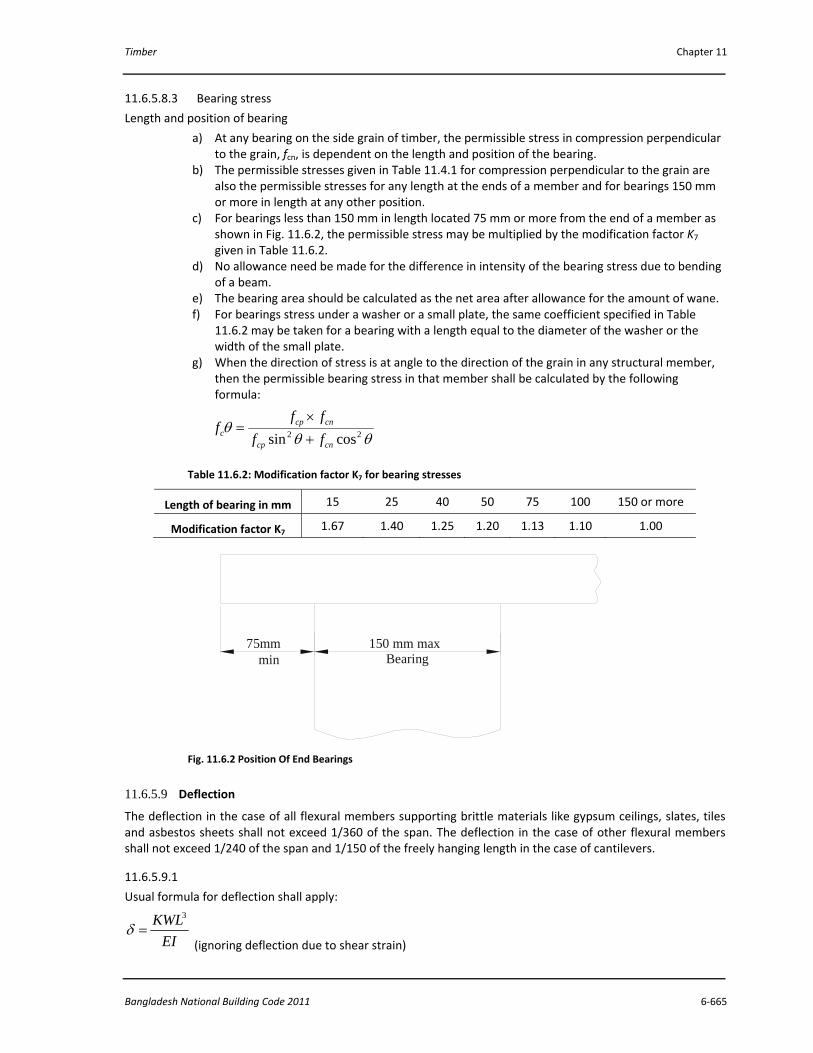
c) For bearings less than 150 mm in length located 75 mm or more from the end of a member as shown in Fig. 11.6.2, the permissible stress may be multiplied by the modification factor K7 given in Table 11.6.2.
d) No allowance need be made for the difference in intensity of the bearing stress due to bending of a beam.
e) The bearing area should be calculated as the net area after allowance for the amount of wane. f) For bearings stress under a washer or a small plate, the same coefficient specified in Table
11.6.2 may be taken for a bearing with a length equal to the diameter of the washer or the width of the small plate.
g) When the direction of stress is at angle to the direction of the grain in any structural member, then the permissible bearing stress in that member shall be calculated by the following formula:
θθθ 22 cossin cncp
cncpc ff
fff
+×
=
Table 11.6.2: Modification factor K7 for bearing stresses
Length of bearing in mm 15 25 40 50 75 100 150 or more
Modification factor K7 1.67 1.40 1.25 1.20 1.13 1.10 1.00
Fig. 11.6.2 Position Of End Bearings
11.6.5.9 Deflection
The deflection in the case of all flexural members supporting brittle materials like gypsum ceilings, slates, tiles and asbestos sheets shall not exceed 1/360 of the span. The deflection in the case of other flexural members shall not exceed 1/240 of the span and 1/150 of the freely hanging length in the case of cantilevers.
11.6.5.9.1
Usual formula for deflection shall apply:
EIKWL3
=δ (ignoring deflection due to shear strain)
75mmmin
150 mm maxBearing

Part 6 Structural Design
6‐666 Vol. 2
K‐values = 1/3 for cantilevers with load at free end,
1/8 for cantilevers with uniformly distributed load,
1/48 for beams supported at both ends with point load at centre, and
5/384 for beams supported at both ends with uniformly distributed load.
11.6.5.9.2 In order to allow the effect of long duration loading on E, for checking deflection in case of beams and joists the effective loads shall be twice the dead load if timber is initially dry.
11.6.5.9.3 Self weight of beam shall be considered in design.
11.6.6 Columns
NOTE — The formulae given are for columns with pin end conditions and the length shall be modified suitably with other end conditions.
11.6.6.1 Solid Columns
Solid columns shall be classified into short, intermediate and long columns depending upon their slenderness ratio (S/d) as follows:
a) Short columns — where S/d does not exceed 11. b) Intermediate columns — where S/d is between 11 and Kg, and c) Long columns — where S/d is greater than Kg.
11.6.6.1.1 For short columns, the permissible compressive stress shall be calculated as follows:
cpc ff =
11.6.6.1.2 For intermediate columns, the permissible compressive stress is calculated by using the following formula:
⎥⎥
⎦
⎤
⎢⎢
⎣
⎡
⎟⎟⎠
⎞⎜⎜⎝
⎛−=
4
311
dKSffg
cpc
11.6.6.1.3 For long columns, the permissible compressive stress shall be calculated by using the following formula:
2)/(329.0
dSEfc =
11.6.6.1.4 In case of solid columns of timber, S/d ratio shall not exceed 50.
11.6.6.1.5 The permissible load on a column of circular cross‐section shall not exceed that permitted for a square column of an equivalent cross‐sectional area.
11.6.6.1.6 For determining S/d ratio of a tapered column, its least dimension shall be taken as the sum of the corresponding least dimensions at the small end of the column and one‐third of the difference between this least dimension at the small end and the corresponding least dimension at the large end, but in no case shall the least dimension for the column be taken as more than one and a half times the least dimension at the small end. The induced stress at the small end of the tapered column shall not exceed the permissible compressive stress in the direction of grain.
11.6.6.2 Built‐up Columns
11.6.6.2.1 Box column
Box columns shall be classified into short, intermediate and long columns as follows:

Timber Chapter 11
Bangladesh National Building Code 2011 6‐667
a) Short columns — where22
21 ddS+
is less than 8;
b) Intermediate columns — where 22
21 ddS+
is between 8 and K9; and
c) Long columns — where 22
21 ddS+
is greater than K9.
11.6.6.2.2 For short columns, the permissible compressive stress shall be calculated as follows:
cpc qff =
11.6.6.2.3 For intermediate columns, the permissible compressive stress shall be obtained using the following formula
⎥⎥
⎦
⎤
⎢⎢
⎣
⎡
⎟⎟
⎠
⎞
⎜⎜
⎝
⎛
+−=
4
21
21
311
ddSqff cpc
11.6.6.2.4 For long columns, the permissible compressive stress shall be calculated by using the following formula:
2
22
21
329.0
⎟⎟
⎠
⎞
⎜⎜
⎝
⎛
+
=
ddS
UEfc
11.6.6.2.5 The following values of U and q, depending upon plank thickness (t) in 11.6.6.2.3 and 11.6.6.2.4, shall be used:
t (mm) U q
25 0.80 1.00
30 0.60 1.00
11.6.6.3 Spaced Columns
11.6.6.3.1 The formulae for solid columns as specified in 6.6.1 are applicable to spaced columns with a restraint factor of 2.5 or 3, depending upon distances of end connectors in the column.
NOTE — A restrained factor of 2.5 for location of centroid group of fasteners at S/20 from end and 3 for location at S/10 to S/20 from end shall be taken.
11.6.6.3.2 For intermediate spaced column, the permissible compressive stress shall be:
⎥⎥⎦
⎤
⎢⎢⎣
⎡⎟⎟⎠
⎞⎜⎜⎝
⎛−=
4
10311
dkSff cpc
11.6.6.3.3 For long spaced columns, the formula shall be:
2)/(5.2329.0
dSEfc×
=

Part 6 Structural Design
6‐668 Vol. 2
11.6.6.3.4 For individual members of spaced columns, S/d ratio shall not exceed 80.
11.6.6.4 Compression members shall not be notched. When it is necessary to pass services through such a member, this shall be effected by means of a bored hole provided that the local stress is calculated and found to be within the permissible stress specified. The distance from the edge of the hole to the edge of the member shall not be less than one quarter of width of the face.
11.6.7 Structural Members Subject to Bending and Axial Stresses
11.6.7.1 Structural members subjected both to bending and axial compression shall be designed to comply with the following formula:
b
ab
c
ac
ff
ff
+
11.6.7.2 Structural members subjected both to bending and axial tension shall be designed to comply with the following formula:
b
ab
t
at
ff
ff
+
11.7 DESIGN OF COMMON STEEL WIRE NAIL JOINTS
11.7.1 General
Nail jointed timber construction is suitable for light and medium timber framings (trusses, etc) up to 15 m spans. With the facilities of readily available materials and simpler workmanship in mono‐chord and split chord constructions, this type of fabrication has a large scope.
11.7.2 Dimensions of Members
11.7.2.1 The dimension of art individual piece of timber (that is, any single member) shall be within the range given below:
a) The minimum thickness of the main members in mono‐chord construction shall be 30 mm. b) The minimum thickness of an individual piece of members in split‐chord construction shall c) The space between two adjacent pieces of timber shall be restricted to a maximum of 3 times
the thickness of the individual piece of timber of the chord member. In case of web members, it may be greater for joining facilities.
11.7.3 No lengthening joint shall preferably be located at a panel point. Generally not more than two, but preferably one, lengthening joint shall be permitted between the two panel points of the members.
11.7.4 Specification and Diameter of Nails
11.7.4.1 The nails used for timber joints shall conform to Part 5 ‘Building Materials’. The nails shall be diamond pointed.
11.7.4.2 The diameter of nail shall be within the limits of one‐eleventh to one‐sixth of the least thickness of members being connected.
11.7.4.3 Where the nails are exposed to be saline conditions, common wire nails shall be galvanized.
11.7.5 Arrangement of Nails in the Joints
The end distances, edge distances and spacings of nails in a nailed joint should be such as to avoid undue splitting of the wood and shall not be less than those given in 11.7.5.1 and 11.7.5.2.

Timber Chapter 11
Bangladesh National Building Code 2011 6‐669
11.7.5.1 Lengthening Joints
The requirement of spacing of nails in a lengthening joint shall be as follows (see also Fig. 11.7.1):
Sl.
No.
Spacing of Nails Type of Stress in the
Joint
Requirement
Min
(1) (2) (3) (4)
i) End distance Tension 12n
Compression 10n
ii) In direction of grain Tension 10n
Compression 5n
iii) Edge distance ‐ 5n
iv) Between row of nails
perpendicular to the grain
‐ 5n
Notes:
1. n is shank diameter of nails
2. The 5n distance between the rows of nails perpendicular to the grain may
be increased subject to the availability of width of the member keeping
edge distance constant.
11.7.5.2 Node Joints
The requirement for spacing of nails in node joints shall be as specified in Fig. 11.7.2 where the members are at right angle and as in Fig. 11.7.3 where the members are inclined to one another at angles other than 90° and subjected to either pure compression or pure tension.
11.7.6 Penetration of Nails
11.7.6.1 For a lap joint when the nails are driven from the side of the thinner member, the length of penetration of nails in the thicker member shall be one and a half times the thickness of the thinner member subject to maximum of the thickness of the thicker member.
11.7.6.2 For butt joints the nails shall be driven through the entire thickness of the joint.
11.7.7 Design Considerations
11.7.7.1 Where a number of nails are used in a joint, the allowable load in lateral resistance shall be the sum of the allowable loads for the individual nails, provided that the centroid of the group of these nails lies on the axis of the member and the spacings conform to 7.5. Where a large number of nails are to be provided at a joint, they should be so arranged that there are more of rows rather than more number of nails in a row.
11.7.7.2 Nails shall, as far as practicable, be arranged so that the line of force in a member passes through the centroid of the group of nails. Where this is not practicable, allowance shall be made for any eccentricity in computing the maximum load on the fixing nails as well as the loads and bending moment in the member.
11.7.7.3 Adjacent nails shall preferably be driven from opposite faces, that is, the nails are driven alternatively from either face of joint.

Part 6 Structural Design
6‐670 Vol. 2
Effective endDistance, 10n min
5n 10n 5n
10n
5n
5n
5n
5n
5n min
5n min
5n min
12n min
10n12n10n
12n min
Effective endDistance, 5n min
n = SHANK DIAMETER OF NAIL
2B MONOCHORD TYPE BUTT JOINT SUBJECT TO TENSION
2A MONOCHORD TYPE BUTT JOINT SUBJECT TO COMPRESSION
11.7.7.4 For a rigid joint, a minimum of 2 nails for nodal joints and 4 nails for lengthening joint shall be driven.
11.7.7.5 Two nails in a horizontal row are better than using the same number of nails in a vertical row.
11.7.8 Special Consideration in Nail‐Jointed Truss Construction
11.7.8.1 The initial upward camber provided at the centre of the lower chord of nail‐jointed timber trusses shall be not less than 1/200 of the effective span for timber structures using seasoned wood and 1/100 for unseasoned or partially seasoned wood.
11.7.8.2 The total combined thickness of the gusset or splice plates on either side of the joint in a mono‐chord type construction shall not be less than one and a half times the thickness of the main members subject to a minimum thickness of 25 mm of individual gusset plate.
Fig. 11.7.1 Spacing of Nails In A Lenghthening Joint ‐ Continued

Timber Chapter 11
Bangladesh National Building Code 2011 6‐671
Fig. 11.7.1 Spacing of Nails In A Lenghthening Joint
Effective endDistance, 10n min
5n 10n 5n
10n min
5n min
5n min
2C SPLIT - CHORD TYPE BUTT JOINT SUBJECT TO COMPRESSION
5n min
5n min
5n min
5n min5n min5n min5n min
10n min 12n min 10n min
Effective endDistance, 5n min
Effective endDistance, 12n min
Effective endDistance, 5n minn = SHANK DIAMETER OF NAIL
2C SPLIT - CHORD TYPE BUTT JOINT SUBJECT TO TENSION
12n min

Part 6 Structural Design
6‐672 Vol. 2
Fig. 11.7.2 Spacing Of Nails Where Members Are At Right Angles To One Another
5n
5n
5n
10n
5n min
10n
5n
5n
5n
5n min
5n
UnloadedEdge
LoadedEdge
3A 3B
10n
5n
5n
10n
5n min
n = SHANK DIAMETER OF NAIL
*5n MAY BE INCREASED TO 10n, IF THE DESIGNED WIDTH OFCORD MEMBER PERMITS. OTHERWISE THE END OF THE LOADEDWEB MEMBER MAY BE EXTENDED BY 5n min
3C

Timber Chapter 11
Bangladesh National Building Code 2011 6‐673
Fig. 11.7.3 Spacing Of Nails At Node Where Members Are Inclined To One Another
10n
5n
10n
5n5n
10n
10n
5n 5n 5n 5n
5n
10n
10n
5n5n
Timber fishPlate
BottomChord
WebMembers
*5n MAY BE INCREASED TO 10n, IF THE DESIGNED WIDTH OF CHORD MEMBER PERMITS.OTHERWISE THE END OF THE LOADED WEB MEMBER MAY BE EXTENDED BY 5n min
4C
n = SHANK DIAMETER OF NAIL
10n
5n
5n
5n
5n
UnloadedEdge
LoadedEdge4A
10n
5n
5n
5n
5n
LoadedEdge
UploadedEdge
4B
*
5n

Part 6 Structural Design
6‐674 Vol. 2
11.7.8.3 The total combined thickness of all spacer blocks or plates or both including outer splice plates, at any joint in a split‐chord type construction shall not be less than one and a half times the total thickness of all the main members at that joint.
11.8 DESIGN OF NAIL LAMINATED TIMBER BEAMS
11.8.1 Method of Arrangement
11.8.1.1 The beam is made up of 20 mm to 30 mm thick planks placed vertically with joints staggered in the adjoining planks with a minimum distance of 300 mm. The planks are laminated with the help of wire nails at regular intervals to take up horizontal shear developed in the beam besides keeping the planks in position (see Fig. 11.8.1).
11.8.1.2 The advantage in laminations lies in dimensional stability, dispersal of defects and better structural performance.
11.8.2 Sizes of Planks and Beams
11.8.2.1 The plank thickness for fabrication of nailed laminated beams recommended are 20,25 and 30 mm.
11.8.2.2 In case of nailed laminated timber beam the maximum depth and length of planks shall be limited to 250 mm and 2000 mm, respectively.
11.8.2.3 In order to obtain the overall width of the beam, the number and thickness of planks to form vertical nailed laminated beams, and also type and size of wire nail shall be as mentioned in Table 10.8.1. The protruding portion of the nail shall be cut off or clenched across the grains.
11.8.3 Design Considerations
11.8.3.1 Nail laminated beams shall be designed in accordance with 11.6.
Table 10.8.1: Number and size of planks and nails for nailed laminated beams
Sl.
No.
Overall Width
of Beam
(mm)
No. of
Planks
Thickness of
each Plank
(mm)
No. and Size of
Nail to be used
(mm)
(1) (2) (3) (4) (5)
i) 50 2 25 80 long 3.55 dia
ii) 60 3 20 ‐do‐
iii) 70 3 (2x25)
(1x20)
‐do‐
iv) 80 4 20 100 long 4.0 dia
v) 90 3 30 ‐do‐
vi) 100 4 25 125 long 5.0 dia
vii) 110 4 (3x30)
(1x20)
‐do‐
viii) 120 4 30 ‐do‐
ix) 150 5 30 150 long 5.0 dia
Notes: A number of combinations of different thickness of planks may be
adopted as long as the minimum and maximum thickness of the planks are
adhered to.

Timber Chapter 11
Bangladesh National Building Code 2011 6‐675
11.8.3.1.1 The deflection in the case of nailed laminated timber beams, joists, purlins, battens and other flexural members supporting brittle materials like gypsum, ceiling slates, tiles and asbestos sheets shall not exceed 1/480 of the span. The deflection in case of other flexural members shall not exceed 1/360 of the span in the case of beams and joists, and 1/225 of the freely hanging length in case of cantilevers.
11.8.3.2 Permissible lateral strength of mild steel wire nails shall be as given in Table 11.4.2 and Table 11.4.3 for Indian Species of timber, which shall apply to nails that have their points cut flush with the faces. For nails clenched across the grains the strength may be increased by 20 percent over the values for nails with points cut flush.
11.8.3.3 Arrangement of Nails
11.8.3.3.1 A minimum number of four nails in a vertical row at regular interval not exceeding 75 mm to take up horizontal shear as well as to keep the planks in position shall be used. Near the joints of the planks this distance may, however, be limited to 5 cm instead of 75 mm.
11.8.3.3.2 Shear shall be calculated at various points of the beam and [he number of nails required shall be accommodated within the distance equal to the depth of the beam, with a minimum of 4 nails in a row at a standard spacing as shown in Fig. 11.8.2.
11.8.3.3.3 If the depth of the beam is more, then the vertical intermediate spacing of nails may be increased proportionately.
11.8.3.3.4 If the nails required at a point are more than that can be accommodated in a row, then these shall he provided lengthwise of the beam within the distance equal to the depth of the beam at standard lengthwise spacing.
11.8.3.3.5 For nailed laminated beam minimum depth of 100 mm for 3.55 mm and 4 mm diameter nails, and 125 mm for 5 mm diameter nails shall be provided.
11.9 DESIGN OF BOLTED CONSTRUCTION JOINTS
11.9.1 General
Bolted joints suit the requirements of prefabrication in small and medium span timber structures for speed and economy in construction. Bolt jointed construction units offer better facilities as regards to workshop ease, mass production of components, transport convenience and re‐assembly at site of work particularly in defence sector for high altitudes and far off situations.
Designing is mainly influenced by the species, size of bolts, moisture conditions and the inclination of loadings to the grains. In principle bolted joints follow the pattern of rivetted joints in steel structures.
11.9.2 Design Considerations
11.9.2.1 Bolted timber construction shall be designed in accordance with 6. The concept of critical section, that is, the net section obtained by deducting the projected area of bolt‐holes from the cross‐sectional area of member is very important for the successful design and economy in timber.
11.9.2.2 Bolt Bearing Strength of Wood
The allowable load for a bolt in a joint consisting of two members (single shear) shall be taken as one half the allowable loads calculated for a three member joint (double shear) for the same t’/d3 ratio. The percentage of safe working compressive stress of timber on bolted joints for different t’/d3 ratios shall be as given in Table 11.9.1.

Part 6 Structural Design
6‐676 Vol. 2
Fig. 11.8.1 Plan And Elevation Of A Typical Nailed Laminated Timber Beam
100
4000
1600
1200
800
4001600
1600
1600
1600
1600
1600
1200
800
400
4 @ 75mm = 300mm25mm THICK TIMBER PLANKS
25
175
25 5025 CAMBER
All dimensions in millimetres.

Timber Chapter 11
Bangladesh National Building Code 2012 6‐677
FIG. 11.8.2 Standard Lengthwise Spacing In Nailed Laminated Beam
11.9.2.2.1
Where a number of bolts are used in a joint, the allowable loads shall be the sum of the allowable loads for the individual bolts.
11.9.2.2.2
he factors for different bolt diameter used in calculating safe bearing stress perpendicular to grain in the joint shall be as given in Table 11.9.2.
11.9.2.3 Dimensions of Members
a) The minimum thickness of the main member in mono‐chord construction shall be 40 mm. b) The minimum thickness of side members shall be 20 mm and shall be half the thickness of main
members. c) The minimum individual thickness of spaced member in split‐chord construction shall be 20 mm
and 25 mm for webs and chord members respectively.
11.9.2.4 Bolts and Bolting
a) The diameter of bolt in the main member shall be so chosen to give larger slenderness (t’/d3) ratio of bolt.
b) There shall be more number of small diameter bolts rather than small number of large diameter bolts in a joint.
c) A minimum of two bolts for nodal joints and four bolts for lengthening joints shall be provided. d) There shall be more number of rows rather than more bolts in a row. e) The bolt holes shall be of such diameter that the bolt can be driven easily. f) Washers shall be used between the head of bolt and wood surface as also between the nut and
wood.
11.9.3 Arrangement of Bolts
11.9.3.1 The following spacing in bolted joints shall be followed (see Fig. 11.9.1):
757550
2020
2020
20
100
6A FOR 3.55 mm AND 4 mm DIAMETER NAILS
757550
2525
2525
25
125
6B FOR 5 mm DIAMETER NAILS
All dimensions in millimetres.

Part 6 Structural Design
6‐678 Vol. 2
a) Spacing of Bolts in a Row — For parallel and perpendicular to grain loading= 4 d3
b) Spacing Between Rows of Bolts
Table 11.9.1: Percentage of safe working compressive stress of timber for bolted joints in double shear
t//d3 ratio Stress Percentage
Parallel to
Grain
Perpendicular to
Grain
λ1 λ2
(1) (2) (3)
1.0 100 100
1.5 100 96
2.0 100 88
2.5 100 80
3.0 100 72
3.5 100 66
4.0 96 60
4.5 90 56
5.0 80 52
5.5 72 49
6.0 65 46
6.5 58 43
7.0 52 40
7.5 46 39
8.0 40 38
8.5 36 36
9.0 34 34
9.5 32 33
10.0 30 31
10.5 ‐ 31
11.0 ‐ 30
11.5 ‐ 30
12.0 ‐ 28
1) For perpendicular to grain loading — 2.5 d3, to 5 d3 (2.5 d3, for t’/d3, ratio of 2 and 5 d3 for t’/d3 ratio of 6 or more. For ratios between 2 to 6 the spacing shall be obtained by interpolation.
2) For parallel to grain loading — At least (N‐ 4) d3, with a minimum of 2.5 d3. Also governed by net area at critical section which should be 80 percent of the total area in bearing under all bolts.
c) End Distance — 7d3 for soft woods in tension, 5 d3 for hardwoods in tension and 4 d3 for all species in compression.
d) Edge Distance
1) For parallel to grain loading 1.5 d3 or half the distance between rows of bolts, whichever is greater.
2) For perpendicular to grain loading, (loaded edge distance) shall be at least 4 d3.
11.9.3.2 For inclined members, the spacing given above for perpendicular and parallel to grain of wood may be used as a guide and bolts arranged at the joint with respect to loading direction.

Timber Chapter 11
Bangladesh National Building Code 2012 6‐679
11.9.3.3 The bolts shall be arranged in such a manner so as to pass the centre of resistance of bolts through the inter‐section of the gravity axis of the members.
11.9.3.4 Staggering of bolts shall be avoided as far as possible in case of members loaded parallel to grain of wood. For loads acting perpendicular to grain of wood, staggering is preferable to avoid splitting due to weather effects.
Table 11.9.2: Bolt diameter factor
Sl. No. Diameter of Bolt
(mm)
Diameter Factor
(dr)
(1) (2) (3)
i) 6 5.70
ii) 10 3.60
iii) 12 3.35
iv) 16 3.15
v) 20 3.05
vi) 22 3.00
vii) 25 2.90
11.9.3.5 Bolting
The bolt holes shall be bored or drilled perpendicular to the surface involved. Forcible driving of the bolts shall be avoided which may cause cracking or splitting of members. A bolt hole of 1.0 mm oversize may be used as a guide for preboring.
11.9.3.5.1 Bolts shall be tightened after one year of completion of structure and subsequently at an interval of two to three years.
11.9.4 Outline for Design of Bolted Joints
Allowable load on one bolt (unit bearing stress) in a joint with wooden splice plates shall not be greater than value of P, R, F as determined by one of the following equations:
a) For Loads Parallel to Grain
1λafP cp= b) For Loads Perpendicular to Grain
fcp dafR 2λ= c) For Loads at an Angle to Grain
θθ 22 cossin RPPRF+
=
11.10 DESIGN OF TIMBER CONNECTOR JOINTS
11.10.1 In large span structures, the members have to transmit very heavy stresses requiring stronger jointing techniques with metallic rings or wooden disc‐dowels. Improvised metallic ring connector is a split circular band of steel made from mild steel pipes. This is placed in the grooves cut into the contact faces of the timber members to be joined, the assembly being held together by means of a connecting bolt.
11.10.1.1 Dimensions of Members Variation of thickness of central (main) and side members affect the load carrying capacity of the joint.

Part 6 Structural Design
6‐680 Vol. 2
Fig. 11.9.1 Typical Spacing Of Bolts In Structural Joints
The thickness of main member shall be at least 57 mm and that of side member 38 mm with length and width f members governed by placement of connector at joint.
The metallic connector shall be so placed that the loaded edge distance is not less than the diameter of the connector and the end distance not less than 1.75 times the diameter on the loaded side.
t
7B SPACING OF BOLTS AT NODE JOINTS
2.5 d for t/d ratio 25 d for t/d ratio 6
1.5d min1.5d min
2d min.
UNLOADEDEDGE
4d
4d
LOADEDEDGE
2.5 d for t/d RATIO 25 d for t/d RATIO 6
1.5d min1.5d min
UNLOADEDEDGE
LOADEDEDGE
4d
4d
2d min.3
3
3
3 3
3 3
3 3
3
3
3
3 3
3 3
3 3
NUT
WASHER
d3
HEADHEXAGONAL
4d 3
4d 3
B
A
B
7d 34d3
7d3
7A SPACING OF BOLTS IN LENTHENING JOINTS(JOINTS LOADED PARALLEL TO GRAIN)
B
A
B
LENG
THO
FBO
LT

Timber Chapter 11
Bangladesh National Building Code 2012 6‐681
11.10.1.2 Design Considerations
Figure 11.10.1 illustrates the primary stresses in a split ring connector joint under tension. The shaded areas represent the part of wood in shear, compression and tension. Related formulae for the same are indicated in Fig. 11.10.1.
For fabrication of structural members, a hole of the required size of the bolt is drilled into the member and a groove is made on the contact faces of the joint.
Fig. 11.10.1 Stress Distribution In A Split Ring Connector
11.10.2 Wooden Disc‐Dowel
11.10.2.1 It is a circular hardwood disc general] y tapered each way from the middle so as to form a double conical frustum. Such a disc is made to fit into preformed holes (recesses), half in one member and the other half in another, the assembly being held by one mild steel bolt through the centre of the disc to act as a coupling for keeping the jointed wooden members from spreading apart.
11.10.2.2 Dimensions of Members
The thickness of dowel may vary from 25 mm to 35 mm anti diameter from 50 mm to 150 mm. The diameter of dowel shall be 3.25 to 3.50 times the thickness.
The edge clearance shall range from 12 mm to 20 mm as per the size of the dowel. The end clearance shall be at least equal to the diameter of dowel for joints subjected to tension and three‐fourth the diameter for compression joints. Disc‐dowel shall be turned from quarter sawn planks of seasoned material.
SPLIT RING CONNECTOR
Wb
a/
d2
d1 d2
t 2
t 2
et 1
2 t 1 - a a/2

Part 6 Structural Design
6‐682 Vol. 2
11.10.2.3 Choice of Species
Wood used for making dowels shall be fairly straight grained, free from excessive liability to shrink and warp, and retain shape well after seasoning species recommended include:
Babul
Sissoo
Pyinkado
Yon
NOTE — Data on the above species as per Table 11.4.1 except for the species Pyinkado, which is not an indigenous species.
11.10.2.4 Design Considerations
Figure 11.10.2 illustrates the forces on dowel in a lap joint and butt joint. Dowel is subjected to shearing at the mid‐section, and compression along the grain at the bearing surfaces. For equal strength in both the forces, formula equations are given in Fig. 11.10.2 to determine the size of dowel.
The making of wooden discs may present some problems in the field, but they may be made in small workshop to the specifications of the designer. This is also economically important. Once the wood fittings are shop tailored and made, the construction process in the field is greatly simplified.
Theoretical safe loads in design shall be confirmed through sample tests.
11.11 GLUED LAMINATED CONSTRUCTION AND FINGER JOINTS
11.11.1 Developments in the field of synthetic adhesive have brought glueing techniques within the range of engineering practice. Timber members of larger cross‐sections and long lengths can be fabricated from small sized planks by the process of gluelam. The term glued laminated timber construction as applied to structural members refers to various laminations glued together, either in straight or curved form, having grain of all laminations essentially parallel to the lengths of the member.
11.11.1.1 Choice of Glue
The adhesive used for glued laminated assembly are ‘gap filling’ type. A ‘filler’ in powder form is introduced in the adhesive. Structural adhesives are supplied either in powder form to which water is added or in resin form to which a hardener or catalyst is added. However, it is important that only boiling water proof (BWP) grade adhesives shall be used for fabrication of gluelam in tropical, high humid climates like India.
11.11.1.2 Manufacturing Schedule
In absence of a systematic flow‐line in a factory, provisions of intermediate technology shall be created for manufacturing structural elements. The schedule involves steps:
a) Drying of planks; b) Planning; c) End‐jointing by scarfs or fingers; d) Machining of laminations; e) Setting up dry assembly of structural unit; f) Application of glue; g) Assembly and pressing the laminations; h) Curing the glue lines, as specified; and i) Finishing, protection and storage.
11.11.2 Finger joints are glued joints connecting timber members end‐to‐end (Fig. 11.11.1). Such joints shall be produced by cutting profiles (tapered projections) in the form of V‐shaped grooves to the ends of timber planks or scantling to be joined, glueing the interfaces and then meeting the two ends together under pressure. Finger joints provide long lengths of timber, ideal for upgrading timber by permitting removal of defects, minimizing warping and reducing wastage by avoiding short off‐cuts.

Timber Chapter 11
Bangladesh National Building Code 2012 6‐683
DOWEL
LAP JOINT
BUTT JOINT
Lap Joint : Bolt in simple tension due to clockwise turning moment on dowel :
Butt Joint : No tilting moment in dowel due to balancing effect [dowels are in shear (no bending, shearing and tensile stress on bolts)]
Size of dowel for equal strength in both shearing and bearing.
ctdSd××=×
24
2π
Where
d= Mid diameter of the dowel
t= Thickness of dowel
s= Safe working stress in shear along grain, and
c= Safe compressive stress along grain.
NOTE‐ Symbols are exclusive in this figure.
Fig. 11.10.2 Distribution Of Forces In Doewl Joint
11.11.2.1 In finger joints the glued surfaces are on the side grain rather than on the end grain and the glue line is stressed in shear rather in tension.
11.11.2.1.1 The figures can be cut from edge‐to‐edge or from face‐to‐face. The difference is mainly in appearance, although bending strength increases if several fingers share the load. Thus a joist is slightly stronger with edge‐to‐edge finger joints and a plank is stronger with face‐to‐face finger joint.
11.11.2.1.2 For structural finger jointed members for interior dry locations, adhesives based on melamine formaldehyde cross linked polyvinyl acetate (PVA) are suited. For high humid and exterior conditions, phenol formaldehyde and resorcinol formaldehyde type adhesives are recommended. Proper adhesives should be selected in consultation with the designer and adhesive manufacturers.
11.11.2.2 Manufacturing Process
In the absence of sophisticated machinery, the finger joints shall be manufactured through intermediate technology with the following steps:

Part 6 Structural Design
6‐684 Vol. 2
a) Drying of wood, b) Removal of knots and other defects, c) Squaring the ends of the laminating planks, d) Cutting the profile of finger joint in the end grain, e) Applying adhesives on the finger interfaces, f) Pressing the joint together at specified pressure, g) Curing of adhesive line at specified temperature, and h) Planning of finger‐jointed planks for smooth surface.
11.11.2.3 Strength
Strength of finger joints depends upon the geometry of the profile for structural purpose; this is generally 50 mm long, 12 mm pitch.
11.11.2.3.1 End joints shall be scattered in adjacent laminations, which shall not be located in very highly stressed outer laminations.
11.11.2.4 Tip thickness will be as small as practically possible.
Fig. 11.11.1 Typical Finger Joint Geometry
ORIENTATION OF FINGER JOINTS
L = FINGER LENGTHP = PITCHt = TIP THICKNESSe = 6°
TIP GAP
pt
L

Timber Chapter 11
Bangladesh National Building Code 2012 6‐685
11.12 LAMINATED VENEER LUMBER
11.12.1 Certain reconstituted lignocellulosic products with fibre oriented along a specific direction have been developed and are being adopted for load bearing applications. Laminated veneer lumber is one such product developed as a result of researches in plantation grown species of wood. Density of laminated veneer lumber ranges from 0.6 to 0.75.
11.12.1.1 Dimensions
Sizes of laminated veneer lumber composite shall be inclusive of margin for dressing and finishing unless manufactured to order. The margin for dressing and finishing shall not exceed 3mm in the width and thickness and 12mmin the length.
11.12.1.2 Permissible Defects
Jointing gaps — Not more than 3 mm wide, provided they are well staggered in their spacing and position between the successive plies.
Slope of grain — Not exceeding 1 in 10 in the face layers.
Tight knot — Three numbers up to 25 mm diameter in one square metre provided they are spaced 300 mm or more apart.
Warp — Not exceeding 1.5 mm per metre length.
11.12.1.3 Strength Requirements
The strength requirements for laminated veneer lumber shall be as per Table 11.12.1.
Table 11.12.1: Requirements of laminated veneer lumber
Sl. No. Properties Requirement
(1) (2) (3)
i) Modulus of rupture (N/mm2), Min 50
ii) Modulus of elasticity (N/mm2), Min 7500
iii) Compressive strength:
a) Parallel to grain (N/mm2), Min 35
b) Perpendicular to grain (N/mm2), Min 50
iv) Horizontal shear:
a) Parallel to laminac (N/mm2), Min 6
b) Perpendicular to laminac (N/mm2), Min 8
v) Tensile strength parallel to grain (N/mm2), Min 55
vi) Screw holding power:
a) Edge (N), Min 2300
b) Face (N), Min 2700
vii) Thickness swelling in 2 h water soaking (percent), Max 3
11.13 DESIGN OF GLUED LAMINATED BEAMS
11.13.1 General Glued laminated structural members shall be fabricated only where there are adequate facilities for accurate sizing and surfacing of planks, uniform application of glue, prompt assembly, and application of adequate pressure and prescribed temperature for setting and curing of the glue. Design and fabrication shall be in accordance with established engineering principles and good practice. A glued laminated beam is a straight member made from a number of laminations assembled both ways either horizontally or vertically. While vertical

Part 6 Structural Design
6‐686 Vol. 2
PLYWOODWEB
PLYWOODWEB PLYWOOD
WOODEN FLANGE(TYPICAL)
BOXDOUBLE - II - SECTION
laminations have limitations in restricting the cross‐section of a beam by width of the plank, horizontally laminated section offers wider scope to the designer in creating even the curved members.
Simple straight beams and joists are used for many structures from small domestic rafters or ridges to the light industrial structures.
11.13.2 Design The design of glue laminated wood elements shall be in accordance with good engineering practice and shall take into consideration the species and grade of timber used, presence of defects, location of end joints in laminations, depth of beams and moisture contents expected while in service. Beams of large spans shall be designed with a suitable camber to assist in achieving the most cost effective section where deflection governs the design. The strength and stiffness of laminated beams is often governed by the quality of outer laminations. Glued laminated beams can be tapered to follow specific roof slopes across a building and/or to commensurate with the varying bending moments.
11.13.3 Material
Laminating boards shall not contain decay, knots or other strength reducing characteristics in excess of those sizes or amounts permitted by specifications. The moisture content shall approach that expected in service and shall in no case exceed 15 percent at the time of glueing. The moisture content of individual laminations in a structural member shall not differ by more than 3 percent at the time of glueing. Glue shall be of type suitable for the intended service of a structural member.
11.13.4 Fabrication/Manufacture
In order to assure a well‐bonded and well‐finished member of true shape and size, all equipments, end‐Jointing, glue spread, assembly, pressing, curing or any other operation in connection with the manufacture of glued structural members shall be in accordance with the available good practices and as per glue manufacturers’ instructions as applicable.
11.14 STRUCTURAL USE OF PLYWOOD
Unlike sawn timber, plywood is a layered panel product comprising veneers of wood bonded together with adjacent layers usually at right angles. As wood is strongest when stressed parallel to grain, and weak perpendicular to grain, the lay up or arrangement of veneers in the panel determines its properties. When the face grain of the plywood is parallel to the direction of stress, veneers parallel to the face grain carry almost all the load. Some information/guidelines for structural use of plywood are given in 11.14.1 to 11.14.3.
11.14.1 The plywood has a high strength to weight ratio, and is dimensionally stable material available in sheets of a number of thicknesses and construction. Plywood can be sawn, drilled and nailed with ordinary wood working tools. The glues used to bond these veneers together are derived from synthetic resins which are set and cured by heating. The properties of adhesives can determine the durability of plywood.
11.14.2 In glued plywood construction, structural plywood is glued to timber resulting in highly efficient and light structural components like web beams (I and box sections), (Fig. 11.15.1 and Fig. 11.15.2) stressed skin panels (Fig. 11.15.3) used for flooring and walling and pre‐fabricated houses, cabins, etc.
Fig. 11.15.1 Typical Cross ‐ Section Of Web Beams

Timber Chapter 11
Bangladesh National Building Code 2012 6‐687
Glueing can be carried out by nail glueing techniques with special clamps. High shear strength of plywood in combination with high flexural strength and stiffness of wood result in structures characterized by high stiffness for even medium spares. Plywood can act as web transmitting shear stress in web bearing or stressed skin or sandwich construction. The effective moment of inertia of web beam and stressed skin construction depends on modular ratio that is, E of wood to E of plywood.
11.14.3 Structural plywood is also very efficient as cladding material in wood frame construction, such as houses. This type of sheathing is capable of resisting racking due to wind and quack forces. Structural plywood has been widely used as diaphragm (horizontal) as in roofing and flooring in timber frame construction. It has been established that 6 mm thick plywood can be used for sheathing and even for web and stressed skin construction, 9‐12 mm thick plywood is suitable for beams, flooring diaphragms, etc. Phenol formaldehyde (PF) and PRF adhesive are suitable for fabrication of glued plywood components. 6 mm‐12 mm thick structural plywood can be very well used as nailed or bolded gussets in fixing members of trusses or lattice griders or trussed rafters.
Normally, scarf joints are used for fixing plywood to required length and timber can be joined by using either finger or scarfjoints. Arch panels, folded plates, shelves are other possibilities with this technique.
11.15 TRUSSED RAFTER
11.15.1 General A roof truss is essentially a plane structure which is very stiff in the plane of the members, that is, the plane in which it is expected to carry loads, but very flexible in every other direction. Thus it can virtually be seen as a deep, narrow girder liable to buckling and twisting under loads. In order, therefore, to reduce this effect, eccentricity of loading and promote prefabrication for economy, low‐pitched trussed rafters are designed with bolt ply/nail ply joints. Plywood as gussets, besides being simple have inherent constructional advantage of grain over solid wood for joints, and a better balance is achievable between the joint strength and the member strength.
Trussed rafters are light weight truss units spaced at close centres for limited spans to carry different types of roof loads. They are made from timber members of uniform thickness fastened together in one plane. The plywood gussets may be nailed or glued to the timber to form the joints. Conceptually a trussed rafter is a triangular pin jointed system, traditionally meant to carry the combined roof weight, cladding services and wind loads. There is considerable scope for saving timber by minimizing the sections through proper design without affecting structural and functional requirements.
Trussed rafters require to be supported only at their ends so that there is no need to provide load bearing internal walls, Purlins, etc are dispensed with and in comparison with traditional methods of construction they use less timber and considerably reduces of site labour, Mass production or reliable units can be carried out under workshop controls.
11.15.2 Design Trussed rafter shall be designed to sustain the dead and imposed loads specified in Part 6 ‘Structural Design: Chapter 2 Loads on Buildings and Structures’ and the combinations expected to occur. Extra stresses/ deflections during handling, transportation and erection shall be taken care of. Structural analysis, use of load‐slip and moment, rotation characteristics of the individual joints may be used if feasible. Alternatively the maximum direct force in a member maybe assessed to be given by an idealized pin‐jointed framework, fully loaded with maximum dead and imposed load in the combination in which they may reasonably be expected to occur.
11.15.3 Timber
The species of timber including plantation grown species which can be used for trussed rafter construction and permissible stresses thereof shall be in accordance with Table 11.4.1. Moisture contents to be as per zonal requirements in accordance with 11.4.4.
11.15.4 Plywood Boiling water resistant (BWR) grade preservative treated plywood shall be used. Introduction of a plywood gusset simplifies the jointing and in addition provides rigidity to the joint. Preservation of plywood and other panel

Part 6 Structural Design
6‐688 Vol. 2
products shall be done in accordance with good practice prescribed by Bangladesh Forest Research Institute, Chittagong.
Fig. 11.15.2 Web Beam Configurations
Fig. 11.15.3 Stressed Skin Panel Construction (Single Skin Or Double Skin)
SPAN UPTO 9m
DOUBLE TAPERD
SPAN UPTO 9m
HAUNCHED
SPAN UPTO 6 - 9m
STRAIGHT
SECTION XX
X
X
PLYWOODSTIFFNER WOODEN
FLANGE
LOWER SKIN
BLOCKING
WEBS
UPPER SKIN

Timber Chapter 11
Bangladesh National Building Code 2012 6‐689
11.16 STRUCTURAL SANDWICHES
11.16.1 General Sandwich constructions are composites of different materials including wood based materials formed by bonding two thin facings of high strength material to a light weight core which provides a combination of desirable properties that are not attainable with the individual constituent materials (Fig. 11.16.1). The thin facings are usually of strong dense material since that are the principal load carrying members of the construction. The core must be stiff enough to ensure the faces remain at the correct distance apart. The sandwiches used as structural elements in building construction shall be adequately designed for their intended services and shall be fabricated only where there are adequate facilities for glueing or otherwise bonding cores to facings to ensure a strong and durable product. The entire assembly provides a structural element of high strength and stiffness in proportion to its mass.
Non‐structural advantages can also be derived by proper selection of facing and core material for example, an impermeable facings can be used to serve as a moisture barrier for walls and roof panels and core may also be selected to provide thermal and/or acoustic insulation, fire resistance, etc, besides the dimensional stability.
Fig. 11.16.1: Sandwitch construction in structural applications
11.16.2 Cores Sandwich cores shall be of such characteristics as to give to the required lateral support to the stressed facings to sustain or transmit the assumed loads or stresses. Core generally carries shearing loads and to support the thin facings due to compressive loads. Core shall maintain the strength and durability under the conditions of service for which their use is recommended. A material with low E and small shear modulus may be suitable.
11.16.3 Facings Facings shall have sufficient strength and rigidity to resist stresses that may come upon them when fabricated into a sandwich construction. They shall be thick enough to carry compressive and tensile stresses and to resist puncture or denting that maybe expected in normal usages.
FACE SHEETS
ADHESIVECORE MATERIAL

Part 6 Structural Design
6‐690 Vol. 2
11.16.4 Designing Structural designing may be comparable to the design of I‐beams, the facings of the sandwich represent the flanges of the I‐beam and the sandwich core I‐beam web.
11.16.5 Tests Tests shall include, as applicable, one or more of the following:
a) Flexural strengtldstiffness, b) Edge‐wise compressions, c) Flat‐wise compression, d) Shear in flat‐wise plane, e) Flat‐wise tensions, f) Flexural creep (creep behaviour of adhesive), g) Cantilever vibrations (dynamic property), and h) Weathering for dimensional stability.
11.17 LAMELLA ROOFING
11.17.1 General The Lamella roofing offers an excellent architectural edifice in timber, amenable to prefabrication, light weight structure with high central clearance. It is essentially an arched structure formed by a system of intersecting skewed arches built‐up of relatively short timber planks of uniform length and cross‐section. Roof is designed as a two hinged arch with a depth equal to the depth of an individual lamella and width equal to the span of the building. The curved lamellas (planks) are bevelled and bored at the ends and bolted together at an angle, forming a network (grid) pattern of mutually braced and stiffened members (Fig. 11.17.1). The design shall be based on the balanced or unbalanced assumed load distribution used for roof arches. Effect of deformation or slip of joints under load on the induced stresses shall be considered in design. Thrust components in both transverse and longitudinal directions of the building due to skewness of the lamella arch shall be adequately resisted. Thrust at lamella joints shall be resisted by the moment of inertia in the continuous lamella and roof sheathening (decking) of lamella roofing. The interaction of arches in two directions adds to the strength and stability against horizontal forces. For design calculations several assumption tested and observed derivations, long‐duration loading factors, seasoning advantages and effects of defects are taken into account.
11.17.2 Lamellas
Planking shall be of a grade of timber that is adequate in strength and stiffness to sustain the assumed loads, forces, thrust and bending moments generated in Lamella roofing. Lamella planks shall be seasoned to a moisture content approximating that they will attain in service. Lamella joints shall be proportioned so that allowable stresses at bearings of the non‐continuous lamellas on the continuous Iamellas or bearings under the head or washer of bolts are not exceeded.
11.17.3 Construction Design and construction of lamella roofs in India assumes the roof surfaces to be cylindrical with every individual lamella an elliptic segment of an elliptical arch of constant curved length but of different curvature. Lamella construction is thus more of an art than science as there is no analytical method available for true generation of schedule of cutting lengths and curvature of curved members forming the lamella grid. Dependence of an engineer on the practical ingenuity of master carpenter is almost final. All the lamella joints shall be accurately cut and fitted to give full bearing without excessive deformation or slip. Bolts at lamella splices shall be adequate to hold the members in their proper position and shall not be over tightened to cause bending of the lamellas or mashing of wood under the bolt heads. Connection of lamellas to the end arches shall be adequate to transmit the thrust or any other force. Sufficient false work or sliding jig shall be provided for the support of lamella roof during actual construction/erection.

Timber Chapter 11
Bangladesh National Building Code 2012 6‐691
Fig. 11.17.1: Typical arrangement of Lamella roofing
HH
rV
RR
r
Vr
WIND BLOCKLAMELLA
NODAL JOINT
BRESSUMMER
LAMELLS GRID
MIDDLE LAMELLA
OUTER LAMELLA
38° to 42°
OUTERBOLTLAMELLA
LAMELLA NODAL JOINT
LOAD REACTION DIAGRAM
LAMELLA GRID
I

Part 6 Structural Design
6‐692 Vol. 2
11.18 NAIL AND SCREW HOLDING POWER OF TIMBER
11.18.1 General One of the most common ways of joining timber pieces to one another is by means of common wire nails and wood screws. Timber is used for structural and nonstructural purposes inform of scantlings, rafters, joists, boarding, crating and packing cases, etc needing suitable methods of joining them. Nevertheless it is the timber which holds the nails or screws and as such pulling of the nails/screws is the chief factor which come into play predominantly. In structural nailed joints, nails are essentially loaded laterally, the design data for which is already available as standard code of practice. Data on holding power of nails/screws in different species is also useful for common commercial purposes. The resistance of mechanical fastenings is a function of the specific gravity of wood, direction of penetration with respect to the grain direction, depth of penetration and the diameter of fastener assuming that the spacing of fasteners should be adequate to preclude splitting of wood.
11.18.2 Nails Nails are probably the most common and familiar fastener. They are of many types and sizes in accordance with the accepted standards [6‐3 A(16)].
In general nails give stronger joints when driven into the side grain of wood than into the end grain. Nails perform best when loaded laterally as compared to axial withdrawal so the nailed joints should be designed for lateral nail bearing in structural design. Information on withdrawal resistance of nails is available and joints may be designed for that kind of loading as and when necessary.
11.18.3 Screw
Next to the hammer driven nails, the wood screw may be the most commonly used fastener. Wood screws are seldom used in structural work because of their primary advantage is in withdrawal resistance, for example, for fixing of ceiling “boards to joists, purlin cleats, besides the door hinges etc. They are of considerable structural importance in fixture design and manufacture. Wood screws are generally finished in a variety of head shapes and manufactured in various lengths for different screw diameters or gauges.
The withdrawal resistance of wood screws is a function of screw diameter, length of engagement of the threaded portion into the member, and the specific gravity of the species of wood. Withdrawal load capacity of wood screws are available for some species and joints may be designed accordingly. End grain load on wood screws are unreliable and wood screws shall not be used for that purpose.
11.19 PROTECTION AGAINST TERMITE ATTACK IN BUILDINGS
11.19.1 Two groups of organisms which affect the mechanical and aesthetic properties of wood in houses are fungi and insects. The most important wood destroying insects belong to termites and beetles. Of about 250 species of wood destroying termites recorded in India, not more than a dozen species attack building causing about 90 percent of the damage to timber and other cellulosic materials. Subterranean termites are the most destructive of the insects that infest wood in houses justifying prevention measures to be incorporated in the design and construction of buildings.
11.19.1.1 Control measures consist in isolating or sealing off the building from termites by chemical and non‐chemical construction techniques. It is recognized that 95 percent damage is due to internal travel of the termites from ground upwards rather than external entry through entrance thus calling upon for appropriate control measures in accordance with good practices [6‐3A(1 8)].
11.19.2 Chemical Methods
Termites live in soil in large colonies and damage the wooden structure in the buildings by eating up the wood or building nests in the wood. Poisoning the soil under and around the building is a normal recommended practice. Spraying of chemical solution in the trenches of foundations in and around walls, areas under floors before and after filling of earth, etc. In already constructed building the treatment can be given by digging trenches all around the building and then giving a liberal dose of chemicals and then closing the trenches.

Timber Chapter 11
Bangladesh National Building Code 2012 6‐693
11.19.3 Wood Preservatives
Natural resistance against organisms of quite a few wood species provides durability of timber without special protection measure. It is a property of heartwood while sapwood is normally always susceptible to attack by organisms. Preservatives should be well applied with sufficient penetration into timber. For engineers, architects and builders, the following are prime considerations for choice of preservatives:
a) Inflammability of treated timber is not increased and mechanical properties are not decreased; b) Compatibility with the glue in laminated wood, plywood and board material; c) Water repellent effect is preferred; d) Possible suitability for priming coat; e) Possibility of painting and other finishes; f) Non‐corrosive nature fasteners; and g) Influence on plastics, in case of metal rubber, tiles and concrete.
11.19.4 Constructional Method
Protection against potential problem of termite attack can simply be carried out by ordinary good construction which prevents a colony from gaining access by:
a) periodic visual observations on termite galleries to be broken off; b) specially formed and properly installed metal shield at plinth level; and c) continuous floor slabs, apron floors and termite grooves on periphery of buildings.