
Part 1 Mainframe - Repeater Buildermanuals.repeater-builder.com/te-files/ACTERN ANT20... · Part 1...
520
Part 1 ANT- 20, ANT-20E, ANT-20SE DominoCOM ANT-20 “Mainframe” Remote Control Operating Manual SCPI Command List
Transcript of Part 1 Mainframe - Repeater Buildermanuals.repeater-builder.com/te-files/ACTERN ANT20... · Part 1...
Part 1
ANT-20, ANT-20E, ANT-20SEDominoCOM ANT-20
“Mainframe”
Remote Control Operating ManualSCPI Command List

Contents
Introduction
1 ANT-20, ANT-20E, ANT-20SE. . . . . . . . . . . . . . . . . . . . . . . . . . . . . . . .I-1
1.1 General information . . . . . . . . . . . . . . . . . . . . . . . . . . . . . . .I-1
1.1.1 Overview . . . . . . . . . . . . . . . . . . . . . . . . . . . . . . . . . . . . . . . . .I-1
1.1.2 Module selection . . . . . . . . . . . . . . . . . . . . . . . . . . . . . . . . . . .I-2
1.1.3 Monitor mode . . . . . . . . . . . . . . . . . . . . . . . . . . . . . . . . . . . . .I-3
1.1.4 LabWindows/CVI driver. . . . . . . . . . . . . . . . . . . . . . . . . . . . . .I-3
1.2 GPIB Remote Control interface . . . . . . . . . . . . . . . . . . . . . .I-3
1.2.1 Items included . . . . . . . . . . . . . . . . . . . . . . . . . . . . . . . . . . . . .I-3
1.2.2 Installation . . . . . . . . . . . . . . . . . . . . . . . . . . . . . . . . . . . . . . . .I-4
1.2.2.1 Overview . . . . . . . . . . . . . . . . . . . . . . . . . . . . . . . . . . . . . . . . .I-4
1.2.2.2 Software installation . . . . . . . . . . . . . . . . . . . . . . . . . . . . . . . .I-4
1.2.2.3 Hardware installation. . . . . . . . . . . . . . . . . . . . . . . . . . . . . . . .I-7
1.2.3 Connecting to GPIB. . . . . . . . . . . . . . . . . . . . . . . . . . . . . . . . .I-8
1.2.4 Device address . . . . . . . . . . . . . . . . . . . . . . . . . . . . . . . . . . . .I-8
1.2.5 Interface functions . . . . . . . . . . . . . . . . . . . . . . . . . . . . . . . . . .I-9
1.2.5.1 Overview . . . . . . . . . . . . . . . . . . . . . . . . . . . . . . . . . . . . . . . . .I-9
1.2.5.2 Device Clear . . . . . . . . . . . . . . . . . . . . . . . . . . . . . . . . . . . . . .I-9
1.3 V.24/V.28 (RS 232) Remote Control interface . . . . . . . . . . .I-9
1.3.1 Items included . . . . . . . . . . . . . . . . . . . . . . . . . . . . . . . . . . . . .I-9
1.3.2 Installation . . . . . . . . . . . . . . . . . . . . . . . . . . . . . . . . . . . . . . . .I-9
1.3.2.1 Software installation . . . . . . . . . . . . . . . . . . . . . . . . . . . . . . .I-10
1.3.3 Connecting to V.24/V.28 (RS 232) . . . . . . . . . . . . . . . . . . . .I-11
1.3.4 Transmission parameters . . . . . . . . . . . . . . . . . . . . . . . . . . .I-13
1.3.5 Interface functions . . . . . . . . . . . . . . . . . . . . . . . . . . . . . . . . .I-14
1.3.5.1 Overview . . . . . . . . . . . . . . . . . . . . . . . . . . . . . . . . . . . . . . . .I-14
1.3.5.2 Device Clear . . . . . . . . . . . . . . . . . . . . . . . . . . . . . . . . . . . . .I-14
2 DominoCOM ANT-20 . . . . . . . . . . . . . . . . . . . . . . . . . . . . . . . . . . . . .I-15
2.1 General information . . . . . . . . . . . . . . . . . . . . . . . . . . . . . .I-15
2.1.1 Items included . . . . . . . . . . . . . . . . . . . . . . . . . . . . . . . . . . . .I-15
2.1.2 Overview . . . . . . . . . . . . . . . . . . . . . . . . . . . . . . . . . . . . . . . .I-15
2.1.3 Changing the configuration . . . . . . . . . . . . . . . . . . . . . . . . . .I-15
2.1.4 ANT-20 mode . . . . . . . . . . . . . . . . . . . . . . . . . . . . . . . . . . . .I-16
i
2.1.5 Module selection . . . . . . . . . . . . . . . . . . . . . . . . . . . . . . . . . . I-17
2.1.6 LabWindows/CVI driver . . . . . . . . . . . . . . . . . . . . . . . . . . . . I-17
2.2 GPIB Remote Control interface . . . . . . . . . . . . . . . . . . . . . I-17
2.2.1 Installation. . . . . . . . . . . . . . . . . . . . . . . . . . . . . . . . . . . . . . . I-18
2.2.1.1 Overview . . . . . . . . . . . . . . . . . . . . . . . . . . . . . . . . . . . . . . . . I-18
2.2.1.2 Configuration for GPIB . . . . . . . . . . . . . . . . . . . . . . . . . . . . . I-18
2.2.1.3 Hardware installation . . . . . . . . . . . . . . . . . . . . . . . . . . . . . . I-18
2.2.2 Connecting to GPIB . . . . . . . . . . . . . . . . . . . . . . . . . . . . . . . I-19
2.2.3 Interface functions. . . . . . . . . . . . . . . . . . . . . . . . . . . . . . . . . I-19
2.2.3.1 Overview . . . . . . . . . . . . . . . . . . . . . . . . . . . . . . . . . . . . . . . . I-19
2.2.3.2 Device Clear . . . . . . . . . . . . . . . . . . . . . . . . . . . . . . . . . . . . . I-20
2.3 V.24/V.28 (RS 232) Remote Control interface. . . . . . . . . . I-21
2.3.1 Installation. . . . . . . . . . . . . . . . . . . . . . . . . . . . . . . . . . . . . . . I-21
2.3.1.1 Overview . . . . . . . . . . . . . . . . . . . . . . . . . . . . . . . . . . . . . . . . I-21
2.3.1.2 Configuration for V.24/V.28 (RS 232) . . . . . . . . . . . . . . . . . . I-21
2.3.2 Connecting to V.24/V.28 (RS 232) . . . . . . . . . . . . . . . . . . . . I-22
2.3.3 Interface functions. . . . . . . . . . . . . . . . . . . . . . . . . . . . . . . . . I-24
2.3.3.1 Overview . . . . . . . . . . . . . . . . . . . . . . . . . . . . . . . . . . . . . . . . I-24
2.3.3.2 Device Clear . . . . . . . . . . . . . . . . . . . . . . . . . . . . . . . . . . . . . I-24
3 TX/RX SCPI block diagram . . . . . . . . . . . . . . . . . . . . . . . . . . . . . . . . I-25
4 Operating information . . . . . . . . . . . . . . . . . . . . . . . . . . . . . . . . . . . . I-26
5 Command hierarchy. . . . . . . . . . . . . . . . . . . . . . . . . . . . . . . . . . . . . . I-27
5.1 Introduction . . . . . . . . . . . . . . . . . . . . . . . . . . . . . . . . . . . . . I-27
5.2 Command hierarchy (generator) . . . . . . . . . . . . . . . . . . . . I-27
5.3 Command hierarchy (receiver) . . . . . . . . . . . . . . . . . . . . . I-28
6 Programming examples. . . . . . . . . . . . . . . . . . . . . . . . . . . . . . . . . . . I-30
6.1 Notation . . . . . . . . . . . . . . . . . . . . . . . . . . . . . . . . . . . . . . . . I-30
6.2 Example 1 (PDH measurement). . . . . . . . . . . . . . . . . . . . . I-30
6.3 Example 2 (SDH C4 measurement) . . . . . . . . . . . . . . . . . . I-31
6.4 Example 3 (SDH overhead) . . . . . . . . . . . . . . . . . . . . . . . . I-32
6.5 Example 4 (SDH overhead measurement) . . . . . . . . . . . . I-32
6.6 Example 5 (SONET STS1-SPE measurement) . . . . . . . . . I-33
ii
6.7 Example 6 (SONET Transport overhead measurement) . . . . . . . . . .I-34
6.8 Example 7 (SONET DS1 ESF testing with LOF inserted) . . . . . . . . . .I-34
7 Release Notes . . . . . . . . . . . . . . . . . . . . . . . . . . . . . . . . . . . . . . . . . . .I-36
7.1 New commands. . . . . . . . . . . . . . . . . . . . . . . . . . . . . . . . . .I-36
7.2 Changed commands. . . . . . . . . . . . . . . . . . . . . . . . . . . . . .I-38
Command reference
1 Common commands . . . . . . . . . . . . . . . . . . . . . . . . . . . . . . . . . . . . . R-1
*CAL?. . . . . . . . . . . . . . . . . . . . . . . . . . . . . . . . . . . . . . . . . . . . . . . . . . . . .R-1*CLS. . . . . . . . . . . . . . . . . . . . . . . . . . . . . . . . . . . . . . . . . . . . . . . . . . . . . .R-2*ESE . . . . . . . . . . . . . . . . . . . . . . . . . . . . . . . . . . . . . . . . . . . . . . . . . . . . .R-2*ESE? . . . . . . . . . . . . . . . . . . . . . . . . . . . . . . . . . . . . . . . . . . . . . . . . . . . .R-3*ESR? . . . . . . . . . . . . . . . . . . . . . . . . . . . . . . . . . . . . . . . . . . . . . . . . . . . .R-3*IDN? . . . . . . . . . . . . . . . . . . . . . . . . . . . . . . . . . . . . . . . . . . . . . . . . . . . . .R-4*OPC . . . . . . . . . . . . . . . . . . . . . . . . . . . . . . . . . . . . . . . . . . . . . . . . . . . . .R-4*OPC? . . . . . . . . . . . . . . . . . . . . . . . . . . . . . . . . . . . . . . . . . . . . . . . . . . . .R-5*OPT? . . . . . . . . . . . . . . . . . . . . . . . . . . . . . . . . . . . . . . . . . . . . . . . . . . . .R-5*RST . . . . . . . . . . . . . . . . . . . . . . . . . . . . . . . . . . . . . . . . . . . . . . . . . . . . .R-5*SRE . . . . . . . . . . . . . . . . . . . . . . . . . . . . . . . . . . . . . . . . . . . . . . . . . . . . .R-6*SRE? . . . . . . . . . . . . . . . . . . . . . . . . . . . . . . . . . . . . . . . . . . . . . . . . . . . .R-6*STB?. . . . . . . . . . . . . . . . . . . . . . . . . . . . . . . . . . . . . . . . . . . . . . . . . . . . .R-7*TST?. . . . . . . . . . . . . . . . . . . . . . . . . . . . . . . . . . . . . . . . . . . . . . . . . . . . .R-7*WAI. . . . . . . . . . . . . . . . . . . . . . . . . . . . . . . . . . . . . . . . . . . . . . . . . . . . . .R-7
2 SYSTEM subsystem . . . . . . . . . . . . . . . . . . . . . . . . . . . . . . . . . . . . . . R-9
:SYST:DATE . . . . . . . . . . . . . . . . . . . . . . . . . . . . . . . . . . . . . . . . . . . . . . .R-9:SYST:DATE? . . . . . . . . . . . . . . . . . . . . . . . . . . . . . . . . . . . . . . . . . . . . . .R-9:SYST:ERR[:NEXT]? . . . . . . . . . . . . . . . . . . . . . . . . . . . . . . . . . . . . . . . . .R-9:SYST:TIME. . . . . . . . . . . . . . . . . . . . . . . . . . . . . . . . . . . . . . . . . . . . . . .R-10:SYST:TIME?. . . . . . . . . . . . . . . . . . . . . . . . . . . . . . . . . . . . . . . . . . . . . .R-10:SYST:VERS? . . . . . . . . . . . . . . . . . . . . . . . . . . . . . . . . . . . . . . . . . . . . .R-10
3 STATUS subsystem . . . . . . . . . . . . . . . . . . . . . . . . . . . . . . . . . . . . . R-11
3.1 Status register structure. . . . . . . . . . . . . . . . . . . . . . . . . . R-11
3.2 STATUS commands . . . . . . . . . . . . . . . . . . . . . . . . . . . . . R-12:STATus:OPERation register . . . . . . . . . . . . . . . . . . . . . . . . . . . . . . . . . .R-12:STAT:OPER:COND? . . . . . . . . . . . . . . . . . . . . . . . . . . . . . . . . . . . . . . .R-12:STAT:OPER:ENAB. . . . . . . . . . . . . . . . . . . . . . . . . . . . . . . . . . . . . . . . .R-13:STAT:OPER:ENAB?. . . . . . . . . . . . . . . . . . . . . . . . . . . . . . . . . . . . . . . .R-13:STAT:OPER[:EVEN]?. . . . . . . . . . . . . . . . . . . . . . . . . . . . . . . . . . . . . . .R-13
iii
:STAT:OPER:NTR . . . . . . . . . . . . . . . . . . . . . . . . . . . . . . . . . . . . . . . . . R-14:STAT:OPER:NTR? . . . . . . . . . . . . . . . . . . . . . . . . . . . . . . . . . . . . . . . . R-14:STAT:OPER:PTR. . . . . . . . . . . . . . . . . . . . . . . . . . . . . . . . . . . . . . . . . . R-14:STAT:OPER:PTR?. . . . . . . . . . . . . . . . . . . . . . . . . . . . . . . . . . . . . . . . . R-15:STAT:PRES . . . . . . . . . . . . . . . . . . . . . . . . . . . . . . . . . . . . . . . . . . . . . . R-15:STATus:QUEStionable register . . . . . . . . . . . . . . . . . . . . . . . . . . . . . . . R-15:STAT:QUES:COND? . . . . . . . . . . . . . . . . . . . . . . . . . . . . . . . . . . . . . . . R-16:STAT:QUES:ENAB . . . . . . . . . . . . . . . . . . . . . . . . . . . . . . . . . . . . . . . . R-16:STAT:QUES:ENAB? . . . . . . . . . . . . . . . . . . . . . . . . . . . . . . . . . . . . . . . R-16:STAT:QUES[:EVEN]? . . . . . . . . . . . . . . . . . . . . . . . . . . . . . . . . . . . . . . R-17:STAT:QUES:NTR . . . . . . . . . . . . . . . . . . . . . . . . . . . . . . . . . . . . . . . . . R-17:STAT:QUES:NTR? . . . . . . . . . . . . . . . . . . . . . . . . . . . . . . . . . . . . . . . . R-17:STAT:QUES:PTR. . . . . . . . . . . . . . . . . . . . . . . . . . . . . . . . . . . . . . . . . . R-18:STAT:QUES:PTR?. . . . . . . . . . . . . . . . . . . . . . . . . . . . . . . . . . . . . . . . . R-18:STAT:SEQ register . . . . . . . . . . . . . . . . . . . . . . . . . . . . . . . . . . . . . . . . R-18:STAT:SEQ:COND? . . . . . . . . . . . . . . . . . . . . . . . . . . . . . . . . . . . . . . . . R-18:STAT:SEQ:ENAB . . . . . . . . . . . . . . . . . . . . . . . . . . . . . . . . . . . . . . . . . R-19:STAT:SEQ:ENAB? . . . . . . . . . . . . . . . . . . . . . . . . . . . . . . . . . . . . . . . . R-19:STAT:SEQ[:EVEN]? . . . . . . . . . . . . . . . . . . . . . . . . . . . . . . . . . . . . . . . R-19:STAT:SEQ:NTR. . . . . . . . . . . . . . . . . . . . . . . . . . . . . . . . . . . . . . . . . . . R-20:STAT:SEQ:NTR?. . . . . . . . . . . . . . . . . . . . . . . . . . . . . . . . . . . . . . . . . . R-20:STAT:SEQ:PTR . . . . . . . . . . . . . . . . . . . . . . . . . . . . . . . . . . . . . . . . . . . R-20:STAT:SEQ:PTR? . . . . . . . . . . . . . . . . . . . . . . . . . . . . . . . . . . . . . . . . . . R-21
4 TRIGGER 1 subsystem . . . . . . . . . . . . . . . . . . . . . . . . . . . . . . . . . . R-23
:ABOR[1] . . . . . . . . . . . . . . . . . . . . . . . . . . . . . . . . . . . . . . . . . . . . . . . . . R-23:INIT[1][:IMM][:ALL] . . . . . . . . . . . . . . . . . . . . . . . . . . . . . . . . . . . . . . . . . R-23:TRIG[1][:SEQ]:SOUR. . . . . . . . . . . . . . . . . . . . . . . . . . . . . . . . . . . . . . . R-24:TRIG[1][:SEQ]:SOUR?. . . . . . . . . . . . . . . . . . . . . . . . . . . . . . . . . . . . . . R-24:TRIG[1][:SEQ]:STIM . . . . . . . . . . . . . . . . . . . . . . . . . . . . . . . . . . . . . . . R-25:TRIG[1][:SEQ]:STIM? . . . . . . . . . . . . . . . . . . . . . . . . . . . . . . . . . . . . . . R-25
5 TRIGGER 2 subsystem . . . . . . . . . . . . . . . . . . . . . . . . . . . . . . . . . . R-27
:ABOR2. . . . . . . . . . . . . . . . . . . . . . . . . . . . . . . . . . . . . . . . . . . . . . . . . . R-27:INIT2[:IMM][:ALL] . . . . . . . . . . . . . . . . . . . . . . . . . . . . . . . . . . . . . . . . . . R-28:TRIG2[:SEQ]:LOG:OBYT. . . . . . . . . . . . . . . . . . . . . . . . . . . . . . . . . . . . R-28:TRIG2[:SEQ]:LOG:OBYT?. . . . . . . . . . . . . . . . . . . . . . . . . . . . . . . . . . . R-29:TRIG2[:SEQ]:LOG:SOUR . . . . . . . . . . . . . . . . . . . . . . . . . . . . . . . . . . . R-30:TRIG2[:SEQ]:LOG:SOUR? . . . . . . . . . . . . . . . . . . . . . . . . . . . . . . . . . . R-30:TRIG2[:SEQ]:LOG:TYPE. . . . . . . . . . . . . . . . . . . . . . . . . . . . . . . . . . . . R-31:TRIG2[:SEQ]:LOG:TYPE?. . . . . . . . . . . . . . . . . . . . . . . . . . . . . . . . . . . R-31:TRIG2[:SEQ]:LOG:VAL . . . . . . . . . . . . . . . . . . . . . . . . . . . . . . . . . . . . . R-32:TRIG2[:SEQ]:LOG:VAL? . . . . . . . . . . . . . . . . . . . . . . . . . . . . . . . . . . . . R-32
6 TRIGGER 3 subsystem . . . . . . . . . . . . . . . . . . . . . . . . . . . . . . . . . . R-33
:ABOR3. . . . . . . . . . . . . . . . . . . . . . . . . . . . . . . . . . . . . . . . . . . . . . . . . . R-33:INIT3[:IMM][:ALL] . . . . . . . . . . . . . . . . . . . . . . . . . . . . . . . . . . . . . . . . . . R-33
iv
7 OUTPUT subsystem . . . . . . . . . . . . . . . . . . . . . . . . . . . . . . . . . . . . . R-35
:OUTP:CLOC[1]:DIV[:STAT] . . . . . . . . . . . . . . . . . . . . . . . . . . . . . . . . . .R-35:OUTP:CLOC[1]:DIV[:STAT]? . . . . . . . . . . . . . . . . . . . . . . . . . . . . . . . . .R-35:OUTP:CLOC2[:STAT]. . . . . . . . . . . . . . . . . . . . . . . . . . . . . . . . . . . . . . .R-36:OUTP:CLOC2[:STAT]?. . . . . . . . . . . . . . . . . . . . . . . . . . . . . . . . . . . . . .R-36:OUTP:CLOC3[:STAT]. . . . . . . . . . . . . . . . . . . . . . . . . . . . . . . . . . . . . . .R-37:OUTP:CLOC3[:STAT]?. . . . . . . . . . . . . . . . . . . . . . . . . . . . . . . . . . . . . .R-37:OUTP[:TEL]:AUX . . . . . . . . . . . . . . . . . . . . . . . . . . . . . . . . . . . . . . . . . .R-38:OUTP[:TEL]:AUX[:STAT] . . . . . . . . . . . . . . . . . . . . . . . . . . . . . . . . . . . .R-38:OUTP[:TEL]:AUX[:STAT]? . . . . . . . . . . . . . . . . . . . . . . . . . . . . . . . . . . .R-38:OUTP[:TEL]:AUX:CODE. . . . . . . . . . . . . . . . . . . . . . . . . . . . . . . . . . . . .R-38:OUTP[:TEL]:AUX:CODE?. . . . . . . . . . . . . . . . . . . . . . . . . . . . . . . . . . . .R-39:OUTP[:TEL]:AUX:TYPE . . . . . . . . . . . . . . . . . . . . . . . . . . . . . . . . . . . . .R-39:OUTP[:TEL]:AUX:TYPE? . . . . . . . . . . . . . . . . . . . . . . . . . . . . . . . . . . . .R-39:OUTP[:TEL]:IBUS:DCC . . . . . . . . . . . . . . . . . . . . . . . . . . . . . . . . . . . . .R-40:OUTP[:TEL]:IBUS:DCC? . . . . . . . . . . . . . . . . . . . . . . . . . . . . . . . . . . . .R-40:OUTP[:TEL]:LINE . . . . . . . . . . . . . . . . . . . . . . . . . . . . . . . . . . . . . . . . . .R-41:OUTP[:TEL]:LINE:CODE . . . . . . . . . . . . . . . . . . . . . . . . . . . . . . . . . . . .R-41:OUTP[:TEL]:LINE:CODE? . . . . . . . . . . . . . . . . . . . . . . . . . . . . . . . . . . .R-41:OUTP[:TEL]:LINE:ERR:CODE | BPV . . . . . . . . . . . . . . . . . . . . . . . . . . .R-42:OUTP[:TEL]:LINE:ERR:CODE | BPV? . . . . . . . . . . . . . . . . . . . . . . . . . .R-42:OUTP[:TEL]:LINE:LEV . . . . . . . . . . . . . . . . . . . . . . . . . . . . . . . . . . . . . .R-42:OUTP[:TEL]:LINE:LEV? . . . . . . . . . . . . . . . . . . . . . . . . . . . . . . . . . . . . .R-43:OUTP[:TEL]:LINE:ROUT . . . . . . . . . . . . . . . . . . . . . . . . . . . . . . . . . . . .R-43:OUTP[:TEL]:LINE:ROUT? . . . . . . . . . . . . . . . . . . . . . . . . . . . . . . . . . . .R-43:OUTP[:TEL]:LINE:TYPE. . . . . . . . . . . . . . . . . . . . . . . . . . . . . . . . . . . . .R-44:OUTP[:TEL]:LINE:TYPE?. . . . . . . . . . . . . . . . . . . . . . . . . . . . . . . . . . . .R-44:OUTP[:TEL]:NRZ . . . . . . . . . . . . . . . . . . . . . . . . . . . . . . . . . . . . . . . . . .R-45:OUTP[:TEL]:NRZ[:STAT] . . . . . . . . . . . . . . . . . . . . . . . . . . . . . . . . . . . .R-45:OUTP[:TEL]:NRZ[:STAT]? . . . . . . . . . . . . . . . . . . . . . . . . . . . . . . . . . . .R-45:OUTP[:TEL]:OPT[1] . . . . . . . . . . . . . . . . . . . . . . . . . . . . . . . . . . . . . . . .R-46:OUTP[:TEL]:OPT[1][:STAT] . . . . . . . . . . . . . . . . . . . . . . . . . . . . . . . . . .R-46:OUTP[:TEL]:OPT[1][:STAT]? . . . . . . . . . . . . . . . . . . . . . . . . . . . . . . . . .R-46:OUTP[:TEL]:OPT[1]:WLEN. . . . . . . . . . . . . . . . . . . . . . . . . . . . . . . . . . .R-47:OUTP[:TEL]:OPT[1]:WLEN?. . . . . . . . . . . . . . . . . . . . . . . . . . . . . . . . . .R-47:OUTP[:TEL]:OPT2 . . . . . . . . . . . . . . . . . . . . . . . . . . . . . . . . . . . . . . . . .R-48:OUTP[:TEL]:OPT2[:STAT] . . . . . . . . . . . . . . . . . . . . . . . . . . . . . . . . . . .R-48:OUTP[:TEL]:OPT2[:STAT]? . . . . . . . . . . . . . . . . . . . . . . . . . . . . . . . . . .R-48:OUTP[:TEL]:OPT2:PWL? . . . . . . . . . . . . . . . . . . . . . . . . . . . . . . . . . . . .R-48:OUTP[:TEL]:OPT2:WLEN. . . . . . . . . . . . . . . . . . . . . . . . . . . . . . . . . . . .R-49:OUTP[:TEL]:OPT2:WLEN?. . . . . . . . . . . . . . . . . . . . . . . . . . . . . . . . . . .R-49:OUTP[:TEL]:OPT3[:STAT] . . . . . . . . . . . . . . . . . . . . . . . . . . . . . . . . . . .R-50:OUTP[:TEL]:OPT3[:STAT]? . . . . . . . . . . . . . . . . . . . . . . . . . . . . . . . . . .R-50:OUTP:TRIG . . . . . . . . . . . . . . . . . . . . . . . . . . . . . . . . . . . . . . . . . . . . . .R-51:OUTP:TRIG:SOUR. . . . . . . . . . . . . . . . . . . . . . . . . . . . . . . . . . . . . . . . .R-51:OUTP:TRIG:SOUR?. . . . . . . . . . . . . . . . . . . . . . . . . . . . . . . . . . . . . . . .R-51:OUTP:TRIG[:STAT] . . . . . . . . . . . . . . . . . . . . . . . . . . . . . . . . . . . . . . . .R-52:OUTP:TRIG[:STAT]? . . . . . . . . . . . . . . . . . . . . . . . . . . . . . . . . . . . . . . .R-52
v
8 SOURCE subsystem . . . . . . . . . . . . . . . . . . . . . . . . . . . . . . . . . . . . R-53
:SOUR:CLOC:FOFF:OFFS. . . . . . . . . . . . . . . . . . . . . . . . . . . . . . . . . . . R-53:SOUR:CLOC:FOFF:OFFS?. . . . . . . . . . . . . . . . . . . . . . . . . . . . . . . . . . R-53:SOUR:CLOC:FOFF[:STAT] . . . . . . . . . . . . . . . . . . . . . . . . . . . . . . . . . . R-53:SOUR:CLOC:FOFF[:STAT]? . . . . . . . . . . . . . . . . . . . . . . . . . . . . . . . . . R-54:SOUR:CLOC:SOUR . . . . . . . . . . . . . . . . . . . . . . . . . . . . . . . . . . . . . . . R-54:SOUR:CLOC:SOUR? . . . . . . . . . . . . . . . . . . . . . . . . . . . . . . . . . . . . . . R-54:SOUR:DATA[:TEL]:AAL1. . . . . . . . . . . . . . . . . . . . . . . . . . . . . . . . . . . . R-55:SOUR:DATA[:TEL]:AAL1:CEM . . . . . . . . . . . . . . . . . . . . . . . . . . . . . . . R-55:SOUR:DATA[:TEL]:AAL1:CEM? . . . . . . . . . . . . . . . . . . . . . . . . . . . . . . R-56:SOUR:DATA[:TEL]:AAL1:ERR[:MODE] . . . . . . . . . . . . . . . . . . . . . . . . R-56:SOUR:DATA[:TEL]:AAL1:ERR[:MODE]? . . . . . . . . . . . . . . . . . . . . . . . R-57:SOUR:DATA[:TEL]:AAL1:ERR:RATE . . . . . . . . . . . . . . . . . . . . . . . . . . R-57:SOUR:DATA[:TEL]:AAL1:ERR:RATE? . . . . . . . . . . . . . . . . . . . . . . . . . R-57:SOUR:DATA[:TEL]:ATM . . . . . . . . . . . . . . . . . . . . . . . . . . . . . . . . . . . . R-58:SOUR:DATA[:TEL]:ATM:ALAR:CLEN. . . . . . . . . . . . . . . . . . . . . . . . . . R-58:SOUR:DATA[:TEL]:ATM:ALAR:CLEN?. . . . . . . . . . . . . . . . . . . . . . . . . R-58:SOUR:DATA[:TEL]:ATM:ALAR[:MODE] . . . . . . . . . . . . . . . . . . . . . . . . R-59:SOUR:DATA[:TEL]:ATM:ALAR[:MODE]? . . . . . . . . . . . . . . . . . . . . . . . R-60:SOUR:DATA[:TEL]:ATM:DIST:BURS:BLO . . . . . . . . . . . . . . . . . . . . . . R-60:SOUR:DATA[:TEL]:ATM:DIST:BURS:BLO? . . . . . . . . . . . . . . . . . . . . . R-60:SOUR:DATA[:TEL]:ATM:DIST:BURS:BLEN . . . . . . . . . . . . . . . . . . . . . R-61:SOUR:DATA[:TEL]:ATM:DIST:BURS:BLEN? . . . . . . . . . . . . . . . . . . . . R-61:SOUR:DATA[:TEL]:ATM:DIST:BURS:BPER. . . . . . . . . . . . . . . . . . . . . R-61:SOUR:DATA[:TEL]:ATM:DIST:BURS:BPER?. . . . . . . . . . . . . . . . . . . . R-62:SOUR:DATA[:TEL]:ATM:DIST:CONS:LOAD. . . . . . . . . . . . . . . . . . . . . R-62:SOUR:DATA[:TEL]:ATM:DIST:CONS:LOAD?. . . . . . . . . . . . . . . . . . . . R-63:SOUR:DATA[:TEL]:ATM:DIST:CONS:RES. . . . . . . . . . . . . . . . . . . . . . R-63:SOUR:DATA[:TEL]:ATM:DIST:CONS:RES?. . . . . . . . . . . . . . . . . . . . . R-63:SOUR:DATA[:TEL]:ATM:DIST:EQU:CDIS . . . . . . . . . . . . . . . . . . . . . . R-64:SOUR:DATA[:TEL]:ATM:DIST:EQU:CDIS? . . . . . . . . . . . . . . . . . . . . . R-64:SOUR:DATA[:TEL]:ATM:DIST:EQU:RES . . . . . . . . . . . . . . . . . . . . . . . R-65:SOUR:DATA[:TEL]:ATM:DIST:EQU:RES? . . . . . . . . . . . . . . . . . . . . . . R-65:SOUR:DATA[:TEL]:ATM:DIST:STAT. . . . . . . . . . . . . . . . . . . . . . . . . . . R-66:SOUR:DATA[:TEL]:ATM:DIST:STAT?. . . . . . . . . . . . . . . . . . . . . . . . . . R-66:SOUR:DATA[:TEL]:ATM:DIST:TYPE . . . . . . . . . . . . . . . . . . . . . . . . . . R-66:SOUR:DATA[:TEL]:ATM:DIST:TYPE? . . . . . . . . . . . . . . . . . . . . . . . . . R-67:SOUR:DATA[:TEL]:ATM:ERR:HEAD:CLEN . . . . . . . . . . . . . . . . . . . . . R-67:SOUR:DATA[:TEL]:ATM:ERR:HEAD:CLEN? . . . . . . . . . . . . . . . . . . . . R-67:SOUR:DATA[:TEL]:ATM:ERR:HEAD[:MODE]. . . . . . . . . . . . . . . . . . . . R-68:SOUR:DATA[:TEL]:ATM:ERR:HEAD[:MODE]?. . . . . . . . . . . . . . . . . . . R-68:SOUR:DATA[:TEL]:ATM:ERR:HEAD:RATE . . . . . . . . . . . . . . . . . . . . . R-69:SOUR:DATA[:TEL]:ATM:ERR:HEAD:RATE? . . . . . . . . . . . . . . . . . . . . R-69:SOUR:DATA[:TEL]:ATM:FILL . . . . . . . . . . . . . . . . . . . . . . . . . . . . . . . . R-69:SOUR:DATA[:TEL]:ATM:FILL? . . . . . . . . . . . . . . . . . . . . . . . . . . . . . . . R-70:SOUR:DATA[:TEL]:ATM:HEAD:CLP. . . . . . . . . . . . . . . . . . . . . . . . . . . R-70:SOUR:DATA[:TEL]:ATM:HEAD:CLP?. . . . . . . . . . . . . . . . . . . . . . . . . . R-70
vi
:SOUR:DATA[:TEL]:ATM:HEAD:GFC . . . . . . . . . . . . . . . . . . . . . . . . . . .R-71:SOUR:DATA[:TEL]:ATM:HEAD:GFC? . . . . . . . . . . . . . . . . . . . . . . . . . .R-71:SOUR:DATA[:TEL]:ATM:HEAD:HEC? . . . . . . . . . . . . . . . . . . . . . . . . . .R-71:SOUR:DATA[:TEL]:ATM:HEAD:PT . . . . . . . . . . . . . . . . . . . . . . . . . . . .R-72:SOUR:DATA[:TEL]:ATM:HEAD:PT? . . . . . . . . . . . . . . . . . . . . . . . . . . .R-72:SOUR:DATA[:TEL]:ATM:HEAD:VCI. . . . . . . . . . . . . . . . . . . . . . . . . . . .R-72:SOUR:DATA[:TEL]:ATM:HEAD:VCI?. . . . . . . . . . . . . . . . . . . . . . . . . . .R-73:SOUR:DATA[:TEL]:ATM:HEAD:VPI . . . . . . . . . . . . . . . . . . . . . . . . . . . .R-73:SOUR:DATA[:TEL]:ATM:HEAD:VPI? . . . . . . . . . . . . . . . . . . . . . . . . . . .R-73:SOUR:DATA[:TEL]:ATM:NINT . . . . . . . . . . . . . . . . . . . . . . . . . . . . . . . .R-74:SOUR:DATA[:TEL]:ATM:NINT? . . . . . . . . . . . . . . . . . . . . . . . . . . . . . . .R-74:SOUR:DATA[:TEL]:ATM:PAYL:SCR . . . . . . . . . . . . . . . . . . . . . . . . . . .R-74:SOUR:DATA[:TEL]:ATM:PAYL:SCR? . . . . . . . . . . . . . . . . . . . . . . . . . .R-75:SOUR:DATA[:TEL]:ATM:PAYL:TYPE . . . . . . . . . . . . . . . . . . . . . . . . . .R-75:SOUR:DATA[:TEL]:ATM:PAYL:TYPE? . . . . . . . . . . . . . . . . . . . . . . . . .R-75:SOUR:DATA[:TEL]:ATM:SOUR . . . . . . . . . . . . . . . . . . . . . . . . . . . . . . .R-76:SOUR:DATA[:TEL]:ATM:SOUR? . . . . . . . . . . . . . . . . . . . . . . . . . . . . . .R-76:SOUR:DATA[:TEL]:ATM:TRAF:BCH:FILL:LIM. . . . . . . . . . . . . . . . . . . .R-76:SOUR:DATA[:TEL]:ATM:TRAF:BCH:FILL:LIM?. . . . . . . . . . . . . . . . . . .R-77:SOUR:DATA[:TEL]:ATM:TRAF:BCH:HEAD:CLP. . . . . . . . . . . . . . . . . .R-77:SOUR:DATA[:TEL]:ATM:TRAF:BCH:HEAD:CLP?. . . . . . . . . . . . . . . . .R-78:SOUR:DATA[:TEL]:ATM:TRAF:BCH:HEAD:GFC . . . . . . . . . . . . . . . . .R-78:SOUR:DATA[:TEL]:ATM:TRAF:BCH:HEAD:GFC? . . . . . . . . . . . . . . . .R-78:SOUR:DATA[:TEL]:ATM:TRAF:BCH:HEAD:HEC? . . . . . . . . . . . . . . . .R-79:SOUR:DATA[:TEL]:ATM:TRAF:BCH:HEAD:PT . . . . . . . . . . . . . . . . . . .R-79:SOUR:DATA[:TEL]:ATM:TRAF:BCH:HEAD:PT? . . . . . . . . . . . . . . . . . .R-79:SOUR:DATA[:TEL]:ATM:TRAF:BCH:HEAD:VCI . . . . . . . . . . . . . . . . . .R-80:SOUR:DATA[:TEL]:ATM:TRAF:BCH:HEAD:VCI? . . . . . . . . . . . . . . . . .R-80:SOUR:DATA[:TEL]:ATM:TRAF:BCH:HEAD:VPI . . . . . . . . . . . . . . . . . .R-81:SOUR:DATA[:TEL]:ATM:TRAF:BCH:HEAD:VPI? . . . . . . . . . . . . . . . . .R-81:SOUR:DATA[:TEL]:ATM:TRAF:BCH:PAYL . . . . . . . . . . . . . . . . . . . . . .R-82:SOUR:DATA[:TEL]:ATM:TRAF:BCH:PAYL? . . . . . . . . . . . . . . . . . . . . .R-82:SOUR:DATA[:TEL]:ATM:TRAF:BCH:STAT . . . . . . . . . . . . . . . . . . . . . .R-82:SOUR:DATA[:TEL]:ATM:TRAF:BCH:STAT? . . . . . . . . . . . . . . . . . . . . .R-83:SOUR:DATA[:TEL]:ATM:TRAF:BCH:TYPE . . . . . . . . . . . . . . . . . . . . . .R-83:SOUR:DATA[:TEL]:ATM:TRAF:BCH:TYPE? . . . . . . . . . . . . . . . . . . . . .R-83:SOUR:DATA[:TEL]:ATM:TRAF:BGEN:DATA. . . . . . . . . . . . . . . . . . . . .R-84:SOUR:DATA[:TEL]:ATM:TRAF:BGEN:DATA?. . . . . . . . . . . . . . . . . . . .R-85:SOUR:DATA[:TEL]:ATM:TRAF:BGEN:STAT. . . . . . . . . . . . . . . . . . . . .R-85:SOUR:DATA[:TEL]:ATM:TRAF:BGEN:STAT? . . . . . . . . . . . . . . . . . . . .R-85:SOUR:DATA[:TEL]:NEL . . . . . . . . . . . . . . . . . . . . . . . . . . . . . . . . . . . . .R-86:SOUR:DATA[:TEL]:NEL? . . . . . . . . . . . . . . . . . . . . . . . . . . . . . . . . . . . .R-86:SOUR:DATA[:TEL]:PAYL:ERR[:MODE]. . . . . . . . . . . . . . . . . . . . . . . . .R-86:SOUR:DATA[:TEL]:PAYL:ERR[:MODE]?. . . . . . . . . . . . . . . . . . . . . . . .R-87:SOUR:DATA[:TEL]:PAYL:ERR:RATE . . . . . . . . . . . . . . . . . . . . . . . . . .R-87:SOUR:DATA[:TEL]:PAYL:ERR:RATE? . . . . . . . . . . . . . . . . . . . . . . . . .R-87:SOUR:DATA[:TEL]:PAYL:PATT. . . . . . . . . . . . . . . . . . . . . . . . . . . . . . .R-88:SOUR:DATA[:TEL]:PAYL:PATT?. . . . . . . . . . . . . . . . . . . . . . . . . . . . . .R-89
vii
:SOUR:DATA[:TEL]:PAYL:SOUR. . . . . . . . . . . . . . . . . . . . . . . . . . . . . . R-89:SOUR:DATA[:TEL]:PAYL:SOUR?. . . . . . . . . . . . . . . . . . . . . . . . . . . . . R-89:SOUR:DATA[:TEL]:PAYL:UWOR . . . . . . . . . . . . . . . . . . . . . . . . . . . . . R-90:SOUR:DATA[:TEL]:PAYL:UWOR? . . . . . . . . . . . . . . . . . . . . . . . . . . . . R-90:SOUR:DATA[:TEL]:PDH . . . . . . . . . . . . . . . . . . . . . . . . . . . . . . . . . . . . R-91:SOUR:DATA[:TEL]:PDH:ALAR:FLEN . . . . . . . . . . . . . . . . . . . . . . . . . . R-91:SOUR:DATA[:TEL]:PDH:ALAR:FLEN? . . . . . . . . . . . . . . . . . . . . . . . . . R-91:SOUR:DATA[:TEL]:PDH:ALAR[:MODE] . . . . . . . . . . . . . . . . . . . . . . . . R-92:SOUR:DATA[:TEL]:PDH:ALAR[:MODE]? . . . . . . . . . . . . . . . . . . . . . . . R-93:SOUR:DATA[:TEL]:PDH:ALAR:SEQ. . . . . . . . . . . . . . . . . . . . . . . . . . . R-94:SOUR:DATA[:TEL]:PDH:ALAR:SEQ?. . . . . . . . . . . . . . . . . . . . . . . . . . R-94:SOUR:DATA[:TEL]:PDH:DS1:CHAN. . . . . . . . . . . . . . . . . . . . . . . . . . . R-95:SOUR:DATA[:TEL]:PDH:DS1:CHAN?. . . . . . . . . . . . . . . . . . . . . . . . . . R-95:SOUR:DATA[:TEL]:PDH:DS1:FRAM. . . . . . . . . . . . . . . . . . . . . . . . . . . R-96:SOUR:DATA[:TEL]:PDH:DS1:FRAM?. . . . . . . . . . . . . . . . . . . . . . . . . . R-96:SOUR:DATA[:TEL]:PDH:DS3:CHAN. . . . . . . . . . . . . . . . . . . . . . . . . . . R-97:SOUR:DATA[:TEL]:PDH:DS3:CHAN?. . . . . . . . . . . . . . . . . . . . . . . . . . R-97:SOUR:DATA[:TEL]:PDH:DS3:FEAC[:ALAR] . . . . . . . . . . . . . . . . . . . . . R-98:SOUR:DATA[:TEL]:PDH:DS3:FEAC[:ALAR]? . . . . . . . . . . . . . . . . . . . . R-98:SOUR:DATA[:TEL]:PDH:DS3:FEAC:LOOP[:TYPE] . . . . . . . . . . . . . . . R-99:SOUR:DATA[:TEL]:PDH:DS3:FEAC:LOOP[:TYPE]? . . . . . . . . . . . . . . R-99:SOUR:DATA[:TEL]:PDH:DS3:FEAC:LOOP:CODE. . . . . . . . . . . . . . . R-100:SOUR:DATA[:TEL]:PDH:DS3:FEAC:LOOP:CODE?. . . . . . . . . . . . . . R-101:SOUR:DATA[:TEL]:PDH:DS3:FRAM. . . . . . . . . . . . . . . . . . . . . . . . . . R-101:SOUR:DATA[:TEL]:PDH:DS3:FRAM?. . . . . . . . . . . . . . . . . . . . . . . . . R-101:SOUR:DATA[:TEL]:PDH:ERR[:MODE] . . . . . . . . . . . . . . . . . . . . . . . . R-102:SOUR:DATA[:TEL]:PDH:ERR[:MODE]? . . . . . . . . . . . . . . . . . . . . . . . R-103:SOUR:DATA[:TEL]:PDH:ERR:RATE. . . . . . . . . . . . . . . . . . . . . . . . . . R-103:SOUR:DATA[:TEL]:PDH:ERR:RATE?. . . . . . . . . . . . . . . . . . . . . . . . . R-103:SOUR:DATA[:TEL]:PDH:FRAM. . . . . . . . . . . . . . . . . . . . . . . . . . . . . . R-104:SOUR:DATA[:TEL]:PDH:FRAM?. . . . . . . . . . . . . . . . . . . . . . . . . . . . . R-104:SOUR:DATA[:TEL]:PDH:M2:ABIT. . . . . . . . . . . . . . . . . . . . . . . . . . . . R-104:SOUR:DATA[:TEL]:PDH:M2:ABIT?. . . . . . . . . . . . . . . . . . . . . . . . . . . R-105:SOUR:DATA[:TEL]:PDH:M2:BNF . . . . . . . . . . . . . . . . . . . . . . . . . . . . R-105:SOUR:DATA[:TEL]:PDH:M2:BNF? . . . . . . . . . . . . . . . . . . . . . . . . . . . R-105:SOUR:DATA[:TEL]:PDH:M2:CHAN. . . . . . . . . . . . . . . . . . . . . . . . . . . R-106:SOUR:DATA[:TEL]:PDH:M2:CHAN?. . . . . . . . . . . . . . . . . . . . . . . . . . R-106:SOUR:DATA[:TEL]:PDH:M2:FRAM. . . . . . . . . . . . . . . . . . . . . . . . . . . R-107:SOUR:DATA[:TEL]:PDH:M2:FRAM?. . . . . . . . . . . . . . . . . . . . . . . . . . R-107:SOUR:DATA[:TEL]:PDH:M2:SBIT. . . . . . . . . . . . . . . . . . . . . . . . . . . . R-108:SOUR:DATA[:TEL]:PDH:M2:SBIT?. . . . . . . . . . . . . . . . . . . . . . . . . . . R-108:SOUR:DATA[:TEL]:PDH:M2:TSL16 . . . . . . . . . . . . . . . . . . . . . . . . . . R-109:SOUR:DATA[:TEL]:PDH:M2:TSL16? . . . . . . . . . . . . . . . . . . . . . . . . . R-109:SOUR:DATA[:TEL]:PDH:M8:BDNB. . . . . . . . . . . . . . . . . . . . . . . . . . . R-110:SOUR:DATA[:TEL]:PDH:M8:BDNB?. . . . . . . . . . . . . . . . . . . . . . . . . . R-110:SOUR:DATA[:TEL]:PDH:M8:CHAN. . . . . . . . . . . . . . . . . . . . . . . . . . . R-111:SOUR:DATA[:TEL]:PDH:M8:CHAN?. . . . . . . . . . . . . . . . . . . . . . . . . . R-111
viii
:SOUR:DATA[:TEL]:PDH:M8:DNB . . . . . . . . . . . . . . . . . . . . . . . . . . . .R-112:SOUR:DATA[:TEL]:PDH:M8:DNB? . . . . . . . . . . . . . . . . . . . . . . . . . . .R-112:SOUR:DATA[:TEL]:PDH:M34:BDNB . . . . . . . . . . . . . . . . . . . . . . . . . .R-113:SOUR:DATA[:TEL]:PDH:M34:BDNB? . . . . . . . . . . . . . . . . . . . . . . . . .R-113:SOUR:DATA[:TEL]:PDH:M34:CHAN . . . . . . . . . . . . . . . . . . . . . . . . . .R-114:SOUR:DATA[:TEL]:PDH:M34:CHAN? . . . . . . . . . . . . . . . . . . . . . . . . .R-114:SOUR:DATA[:TEL]:PDH:M34:DNB . . . . . . . . . . . . . . . . . . . . . . . . . . .R-115:SOUR:DATA[:TEL]:PDH:M34:DNB? . . . . . . . . . . . . . . . . . . . . . . . . . .R-115:SOUR:DATA[:TEL]:PDH:M34:FTYP. . . . . . . . . . . . . . . . . . . . . . . . . . .R-116:SOUR:DATA[:TEL]:PDH:M34:FTYP?. . . . . . . . . . . . . . . . . . . . . . . . . .R-116:SOUR:DATA[:TEL]:PDH:M34:G832:OVER:DATA . . . . . . . . . . . . . . . .R-117:SOUR:DATA[:TEL]:PDH:M34:G832:OVER:DATA? . . . . . . . . . . . . . . .R-117:SOUR:DATA[:TEL]:PDH:M34:G832:OVER:DATA:BLOC . . . . . . . . . .R-118:SOUR:DATA[:TEL]:PDH:M34:G832:OVER:DATA:BLOC? . . . . . . . . .R-118:SOUR:DATA[:TEL]:PDH:M34:G832:OVER:PRES. . . . . . . . . . . . . . . .R-119:SOUR:DATA[:TEL]:PDH:M34:G832:OVER:TRAC. . . . . . . . . . . . . . . .R-120:SOUR:DATA[:TEL]:PDH:M34:G832:OVER:TRAC?. . . . . . . . . . . . . . .R-120:SOUR:DATA[:TEL]:PDH:M140:CHAN . . . . . . . . . . . . . . . . . . . . . . . . .R-121:SOUR:DATA[:TEL]:PDH:M140:CHAN? . . . . . . . . . . . . . . . . . . . . . . . .R-121:SOUR:DATA[:TEL]:PDH:M140:DNYY . . . . . . . . . . . . . . . . . . . . . . . . .R-122:SOUR:DATA[:TEL]:PDH:M140:DNYY? . . . . . . . . . . . . . . . . . . . . . . . .R-122:SOUR:DATA[:TEL]:PDH:M140:FTYP. . . . . . . . . . . . . . . . . . . . . . . . . .R-123:SOUR:DATA[:TEL]:PDH:M140:FTYP?. . . . . . . . . . . . . . . . . . . . . . . . .R-123:SOUR:DATA[:TEL]:PDH:M140:G832:OVER:DATA . . . . . . . . . . . . . . .R-124:SOUR:DATA[:TEL]:PDH:M140:G832:OVER:DATA? . . . . . . . . . . . . . .R-124:SOUR:DATA[:TEL]:PDH:M140:G832:OVER:DATA:BLOC . . . . . . . . .R-125:SOUR:DATA[:TEL]:PDH:M140:G832:OVER:DATA:BLOC? . . . . . . . .R-126:SOUR:DATA[:TEL]:PDH:M140:G832:OVER:PRES. . . . . . . . . . . . . . .R-126:SOUR:DATA[:TEL]:PDH:M140:G832:OVER:TRAC. . . . . . . . . . . . . . .R-127:SOUR:DATA[:TEL]:PDH:M140:G832:OVER:TRAC?. . . . . . . . . . . . . .R-127:SOUR:DATA[:TEL]:PDH:PAYL:TYPE . . . . . . . . . . . . . . . . . . . . . . . . .R-128:SOUR:DATA[:TEL]:PDH:PAYL:TYPE? . . . . . . . . . . . . . . . . . . . . . . . .R-128:SOUR:DATA[:TEL]:PDH:RATE . . . . . . . . . . . . . . . . . . . . . . . . . . . . . .R-129:SOUR:DATA[:TEL]:PDH:RATE? . . . . . . . . . . . . . . . . . . . . . . . . . . . . .R-130:SOUR:DATA[:TEL]:PLCP. . . . . . . . . . . . . . . . . . . . . . . . . . . . . . . . . . .R-131:SOUR:DATA[:TEL]:PLCP:ALAR[:MODE]. . . . . . . . . . . . . . . . . . . . . . .R-131:SOUR:DATA[:TEL]:PLCP:ALAR[:MODE]?. . . . . . . . . . . . . . . . . . . . . .R-131:SOUR:DATA[:TEL]:PLCP:ALAR:FLEN . . . . . . . . . . . . . . . . . . . . . . . .R-132:SOUR:DATA[:TEL]:PLCP:ALAR:FLEN? . . . . . . . . . . . . . . . . . . . . . . .R-132:SOUR:DATA[:TEL]:PLCP:ERR[:MODE]. . . . . . . . . . . . . . . . . . . . . . . .R-133:SOUR:DATA[:TEL]:PLCP:ERR[:MODE]?. . . . . . . . . . . . . . . . . . . . . . .R-133:SOUR:DATA[:TEL]:PLCP:ERR:RATE . . . . . . . . . . . . . . . . . . . . . . . . .R-134:SOUR:DATA[:TEL]:PLCP:ERR:RATE? . . . . . . . . . . . . . . . . . . . . . . . .R-134:SOUR:DATA[:TEL]:SDH. . . . . . . . . . . . . . . . . . . . . . . . . . . . . . . . . . . .R-135:SOUR:DATA[:TEL]:SDH:ALAR:FLEN . . . . . . . . . . . . . . . . . . . . . . . . .R-135:SOUR:DATA[:TEL]:SDH:ALAR:FLEN? . . . . . . . . . . . . . . . . . . . . . . . .R-135:SOUR:DATA[:TEL]:SDH:ALAR[:MODE]. . . . . . . . . . . . . . . . . . . . . . . .R-136:SOUR:DATA[:TEL]:SDH:ALAR[:MODE]?. . . . . . . . . . . . . . . . . . . . . . .R-140
ix
:SOUR:DATA[:TEL]:SDH:BPOV:DATA . . . . . . . . . . . . . . . . . . . . . . . . R-140:SOUR:DATA[:TEL]:SDH:BPOV:DATA? . . . . . . . . . . . . . . . . . . . . . . . R-140:SOUR:DATA[:TEL]:SDH:BPOV:DATA:BLOC . . . . . . . . . . . . . . . . . . . R-141:SOUR:DATA[:TEL]:SDH:BPOV:DATA:BLOC? . . . . . . . . . . . . . . . . . . R-142:SOUR:DATA[:TEL]:SDH:BPOV:HPTR . . . . . . . . . . . . . . . . . . . . . . . . R-142:SOUR:DATA[:TEL]:SDH:BPOV:HPTR? . . . . . . . . . . . . . . . . . . . . . . . R-143:SOUR:DATA[:TEL]:SDH:BPOV:PRES . . . . . . . . . . . . . . . . . . . . . . . . R-143:SOUR:DATA[:TEL]:SDH:CHAN. . . . . . . . . . . . . . . . . . . . . . . . . . . . . . R-144:SOUR:DATA[:TEL]:SDH:CHAN?. . . . . . . . . . . . . . . . . . . . . . . . . . . . . R-145:SOUR:DATA[:TEL]:SDH:CONC:DPO2 . . . . . . . . . . . . . . . . . . . . . . . . R-146:SOUR:DATA[:TEL]:SDH:CONC:DPO2? . . . . . . . . . . . . . . . . . . . . . . . R-146:SOUR:DATA[:TEL]:SDH:CONC:DPO3 . . . . . . . . . . . . . . . . . . . . . . . . R-147:SOUR:DATA[:TEL]:SDH:CONC:DPO3? . . . . . . . . . . . . . . . . . . . . . . . R-147:SOUR:DATA[:TEL]:SDH:CONC:DPO4 . . . . . . . . . . . . . . . . . . . . . . . . R-148:SOUR:DATA[:TEL]:SDH:CONC:DPO4? . . . . . . . . . . . . . . . . . . . . . . . R-148:SOUR:DATA[:TEL]:SDH:CONC:POIN[:ACT] . . . . . . . . . . . . . . . . . . . R-149:SOUR:DATA[:TEL]:SDH:CONC:POIN[:ACT]? . . . . . . . . . . . . . . . . . . R-149:SOUR:DATA[:TEL]:SDH:CONC:POV2:DATA . . . . . . . . . . . . . . . . . . . R-150:SOUR:DATA[:TEL]:SDH:CONC:POV2:DATA? . . . . . . . . . . . . . . . . . . R-150:SOUR:DATA[:TEL]:SDH:CONC:POV2:DATA:BLOC . . . . . . . . . . . . . R-151:SOUR:DATA[:TEL]:SDH:CONC:POV2:DATA:BLOC? . . . . . . . . . . . . R-151:SOUR:DATA[:TEL]:SDH:CONC:POV2:MODE . . . . . . . . . . . . . . . . . . R-152:SOUR:DATA[:TEL]:SDH:CONC:POV2:MODE? . . . . . . . . . . . . . . . . . R-152:SOUR:DATA[:TEL]:SDH:CONC:POV2:PRES. . . . . . . . . . . . . . . . . . . R-153:SOUR:DATA[:TEL]:SDH:CONC:POV3:DATA . . . . . . . . . . . . . . . . . . . R-154:SOUR:DATA[:TEL]:SDH:CONC:POV3:DATA? . . . . . . . . . . . . . . . . . . R-154:SOUR:DATA[:TEL]:SDH:CONC:POV3:DATA:BLOC . . . . . . . . . . . . . R-155:SOUR:DATA[:TEL]:SDH:CONC:POV3:DATA:BLOC? . . . . . . . . . . . . R-155:SOUR:DATA[:TEL]:SDH:CONC:POV3:MODE . . . . . . . . . . . . . . . . . . R-156:SOUR:DATA[:TEL]:SDH:CONC:POV3:MODE? . . . . . . . . . . . . . . . . . R-156:SOUR:DATA[:TEL]:SDH:CONC:POV3:PRES. . . . . . . . . . . . . . . . . . . R-157:SOUR:DATA[:TEL]:SDH:CONC:POV4:DATA . . . . . . . . . . . . . . . . . . . R-158:SOUR:DATA[:TEL]:SDH:CONC:POV4:DATA? . . . . . . . . . . . . . . . . . . R-158:SOUR:DATA[:TEL]:SDH:CONC:POV4:DATA:BLOC . . . . . . . . . . . . . R-159:SOUR:DATA[:TEL]:SDH:CONC:POV4:DATA:BLOC? . . . . . . . . . . . . R-159:SOUR:DATA[:TEL]:SDH:CONC:POV4:MODE . . . . . . . . . . . . . . . . . . R-160:SOUR:DATA[:TEL]:SDH:CONC:POV4:MODE? . . . . . . . . . . . . . . . . . R-160:SOUR:DATA[:TEL]:SDH:CONC:POV4:PRES. . . . . . . . . . . . . . . . . . . R-161:SOUR:DATA[:TEL]:SDH:ERR:FLEN . . . . . . . . . . . . . . . . . . . . . . . . . . R-162:SOUR:DATA[:TEL]:SDH:ERR:FLEN? . . . . . . . . . . . . . . . . . . . . . . . . . R-162:SOUR:DATA[:TEL]:SDH:ERR:MASK:HBIP. . . . . . . . . . . . . . . . . . . . . R-163:SOUR:DATA[:TEL]:SDH:ERR:MASK:HBIP?. . . . . . . . . . . . . . . . . . . . R-163:SOUR:DATA[:TEL]:SDH:ERR:MASK:LBIP . . . . . . . . . . . . . . . . . . . . . R-164:SOUR:DATA[:TEL]:SDH:ERR:MASK:LBIP? . . . . . . . . . . . . . . . . . . . . R-164:SOUR:DATA[:TEL]:SDH:ERR[:MODE] . . . . . . . . . . . . . . . . . . . . . . . . R-165:SOUR:DATA[:TEL]:SDH:ERR[:MODE]? . . . . . . . . . . . . . . . . . . . . . . . R-166:SOUR:DATA[:TEL]:SDH:ERR:RATE. . . . . . . . . . . . . . . . . . . . . . . . . . R-167:SOUR:DATA[:TEL]:SDH:ERR:RATE?. . . . . . . . . . . . . . . . . . . . . . . . . R-167
x
:SOUR:DATA[:TEL]:SDH:MAPP . . . . . . . . . . . . . . . . . . . . . . . . . . . . . .R-168:SOUR:DATA[:TEL]:SDH:MAPP? . . . . . . . . . . . . . . . . . . . . . . . . . . . . .R-168:SOUR:DATA[:TEL]:SDH:MAPP:OFFS. . . . . . . . . . . . . . . . . . . . . . . . .R-169:SOUR:DATA[:TEL]:SDH:MAPP:OFFS?. . . . . . . . . . . . . . . . . . . . . . . .R-169:SOUR:DATA[:TEL]:SDH:MAPP:CONC[:MODE] . . . . . . . . . . . . . . . . .R-170:SOUR:DATA[:TEL]:SDH:MAPP:CONC[:MODE]? . . . . . . . . . . . . . . . .R-170:SOUR:DATA[:TEL]:SDH:MAPP:CONC:CSIZ. . . . . . . . . . . . . . . . . . . .R-171:SOUR:DATA[:TEL]:SDH:MAPP:CONC:CSIZ?. . . . . . . . . . . . . . . . . . .R-171:SOUR:DATA[:TEL]:SDH:MAPP:TUFL . . . . . . . . . . . . . . . . . . . . . . . . .R-172:SOUR:DATA[:TEL]:SDH:MAPP:TUFL? . . . . . . . . . . . . . . . . . . . . . . . .R-172Overview :SOUR:DATA[:TEL]:SDH:OVER[i]: ... commands . . . . . . . . .R-173:SOUR:DATA[:TEL]:SDH:OVER:BYT . . . . . . . . . . . . . . . . . . . . . . . . . .R-174:SOUR:DATA[:TEL]:SDH:OVER:BYT? . . . . . . . . . . . . . . . . . . . . . . . . .R-174:SOUR:DATA[:TEL]:SDH:OVER[i]:DATA . . . . . . . . . . . . . . . . . . . . . . .R-175:SOUR:DATA[:TEL]:SDH:OVER[i]:DATA? . . . . . . . . . . . . . . . . . . . . . .R-176:SOUR:DATA[:TEL]:SDH:OVER[i]:DATA:BLOC . . . . . . . . . . . . . . . . . .R-177:SOUR:DATA[:TEL]:SDH:OVER[i]:DATA:BLOC? . . . . . . . . . . . . . . . . .R-178:SOUR:DATA[:TEL]:SDH:OVER:INS[:SOUR] . . . . . . . . . . . . . . . . . . . .R-178:SOUR:DATA[:TEL]:SDH:OVER:INS[:SOUR]? . . . . . . . . . . . . . . . . . . .R-178:SOUR:DATA[:TEL]:SDH:OVER[i]:PRES . . . . . . . . . . . . . . . . . . . . . . .R-179:SOUR:DATA[:TEL]:SDH:OVER[i]:RDAT . . . . . . . . . . . . . . . . . . . . . . .R-182:SOUR:DATA[:TEL]:SDH:OVER[i]:RDAT? . . . . . . . . . . . . . . . . . . . . . .R-183:SOUR:DATA[:TEL]:SDH:OVER[i]:RDAT:BLOC . . . . . . . . . . . . . . . . . .R-183:SOUR:DATA[:TEL]:SDH:OVER[i]:RDAT:BLOC? . . . . . . . . . . . . . . . . .R-184:SOUR:DATA[:TEL]:SDH:OVER:RSTR. . . . . . . . . . . . . . . . . . . . . . . . .R-185:SOUR:DATA[:TEL]:SDH:OVER:RSTR?. . . . . . . . . . . . . . . . . . . . . . . .R-185:SOUR:DATA[:TEL]:SDH:OVER:SEQ[:ACT]. . . . . . . . . . . . . . . . . . . . .R-186:SOUR:DATA[:TEL]:SDH:OVER:SEQ[:ACT]?. . . . . . . . . . . . . . . . . . . .R-187:SOUR:DATA[:TEL]:SDH:OVER:SEQ:MNP:DATA . . . . . . . . . . . . . . . .R-187:SOUR:DATA[:TEL]:SDH:OVER:SEQ:MNP:DATA? . . . . . . . . . . . . . . .R-188:SOUR:DATA[:TEL]:SDH:OVER:SEQ:POS:POH . . . . . . . . . . . . . . . . .R-189:SOUR:DATA[:TEL]:SDH:OVER:SEQ:POS:POH? . . . . . . . . . . . . . . . .R-189:SOUR:DATA[:TEL]:SDH:OVER:SEQ:POS:SOH | TOH . . . . . . . . . . . .R-190:SOUR:DATA[:TEL]:SDH:OVER:SEQ:POS:SOH? . . . . . . . . . . . . . . . .R-190:SOUR:DATA[:TEL]:SDH:OVER:SEQ:TCM:DATA . . . . . . . . . . . . . . . .R-191:SOUR:DATA[:TEL]:SDH:OVER:SEQ:TCM:DATA? . . . . . . . . . . . . . . .R-191:SOUR:DATA[:TEL]:SDH:OVER:SEQ:TYPE. . . . . . . . . . . . . . . . . . . . .R-192:SOUR:DATA[:TEL]:SDH:OVER:SEQ:TYPE?. . . . . . . . . . . . . . . . . . . .R-192:SOUR:DATA[:TEL]:SDH:OVER:SEQ:TCM:DATA:BLOC. . . . . . . . . . .R-193:SOUR:DATA[:TEL]:SDH:OVER:SEQ:TCM:DATA:BLOC?. . . . . . . . . .R-194:SOUR:DATA[:TEL]:SDH:PAYL:TYPE . . . . . . . . . . . . . . . . . . . . . . . . .R-195:SOUR:DATA[:TEL]:SDH:PAYL:TYPE? . . . . . . . . . . . . . . . . . . . . . . . .R-195
Overview of pointer sequences . . . . . . . . . . . . . . . . . . . . . . . . . . . . . . .R-196
:SOUR:DATA[:TEL]:SDH:POIN[:ACT]. . . . . . . . . . . . . . . . . . . . . . . . . .R-198:SOUR:DATA[:TEL]:SDH:POIN[:ACT]?. . . . . . . . . . . . . . . . . . . . . . . . .R-198:SOUR:DATA[:TEL]:SDH:POIN:ADD:PER . . . . . . . . . . . . . . . . . . . . . .R-199:SOUR:DATA[:TEL]:SDH:POIN:ADD:PER? . . . . . . . . . . . . . . . . . . . . .R-199
xi
:SOUR:DATA[:TEL]:SDH:POIN:ADD[:STAT] . . . . . . . . . . . . . . . . . . . . R-199:SOUR:DATA[:TEL]:SDH:POIN:ADD[:STAT]? . . . . . . . . . . . . . . . . . . . R-200:SOUR:DATA[:TEL]:SDH:POIN:APER . . . . . . . . . . . . . . . . . . . . . . . . . R-200:SOUR:DATA[:TEL]:SDH:POIN:APER? . . . . . . . . . . . . . . . . . . . . . . . . R-200:SOUR:DATA[:TEL]:SDH:POIN:CANC:PER. . . . . . . . . . . . . . . . . . . . . R-201:SOUR:DATA[:TEL]:SDH:POIN:CANC:PER?. . . . . . . . . . . . . . . . . . . . R-201:SOUR:DATA[:TEL]:SDH:POIN:CANC[:STAT]. . . . . . . . . . . . . . . . . . . R-201:SOUR:DATA[:TEL]:SDH:POIN:CANC[:STAT]?. . . . . . . . . . . . . . . . . . R-202:SOUR:DATA[:TEL]:SDH:POIN:IPER. . . . . . . . . . . . . . . . . . . . . . . . . . R-202:SOUR:DATA[:TEL]:SDH:POIN:IPER?. . . . . . . . . . . . . . . . . . . . . . . . . R-202:SOUR:DATA[:TEL]:SDH:POIN:MODE . . . . . . . . . . . . . . . . . . . . . . . . R-203:SOUR:DATA[:TEL]:SDH:POIN:MODE? . . . . . . . . . . . . . . . . . . . . . . . R-203:SOUR:DATA[:TEL]:SDH:POIN:NDFL . . . . . . . . . . . . . . . . . . . . . . . . . R-203:SOUR:DATA[:TEL]:SDH:POIN:NDFL? . . . . . . . . . . . . . . . . . . . . . . . . R-204:SOUR:DATA[:TEL]:SDH:POIN:NUMB. . . . . . . . . . . . . . . . . . . . . . . . . R-204:SOUR:DATA[:TEL]:SDH:POIN:NUMB?. . . . . . . . . . . . . . . . . . . . . . . . R-204:SOUR:DATA[:TEL]:SDH:POIN:PER . . . . . . . . . . . . . . . . . . . . . . . . . . R-205:SOUR:DATA[:TEL]:SDH:POIN:PER? . . . . . . . . . . . . . . . . . . . . . . . . . R-205:SOUR:DATA[:TEL]:SDH:POIN:SEQ:DIR . . . . . . . . . . . . . . . . . . . . . . R-205:SOUR:DATA[:TEL]:SDH:POIN:SEQ:DIR? . . . . . . . . . . . . . . . . . . . . . R-206:SOUR:DATA[:TEL]:SDH:POIN:SEQ:TYPE . . . . . . . . . . . . . . . . . . . . . R-206:SOUR:DATA[:TEL]:SDH:POIN:SEQ:TYPE? . . . . . . . . . . . . . . . . . . . . R-206:SOUR:DATA[:TEL]:SDH:POIN:SSB . . . . . . . . . . . . . . . . . . . . . . . . . . R-207:SOUR:DATA[:TEL]:SDH:POIN:SSB? . . . . . . . . . . . . . . . . . . . . . . . . . R-207:SOUR:DATA[:TEL]:SDH:POIN:VAL . . . . . . . . . . . . . . . . . . . . . . . . . . R-207:SOUR:DATA[:TEL]:SDH:POIN:VAL? . . . . . . . . . . . . . . . . . . . . . . . . . R-207:SOUR:DATA[:TEL]:SDH:POV:DATA. . . . . . . . . . . . . . . . . . . . . . . . . . R-208:SOUR:DATA[:TEL]:SDH:POV:DATA?. . . . . . . . . . . . . . . . . . . . . . . . . R-208:SOUR:DATA[:TEL]:SDH:POV:DATA:BLOC . . . . . . . . . . . . . . . . . . . . R-209:SOUR:DATA[:TEL]:SDH:POV:DATA:BLOC? . . . . . . . . . . . . . . . . . . . R-209:SOUR:DATA[:TEL]:SDH:POV:HPTR. . . . . . . . . . . . . . . . . . . . . . . . . . R-210:SOUR:DATA[:TEL]:SDH:POV:HPTR?. . . . . . . . . . . . . . . . . . . . . . . . . R-210:SOUR:DATA[:TEL]:SDH:POV:HSEQ . . . . . . . . . . . . . . . . . . . . . . . . . R-211:SOUR:DATA[:TEL]:SDH:POV:HSEQ? . . . . . . . . . . . . . . . . . . . . . . . . R-211:SOUR:DATA[:TEL]:SDH:POV:PRES. . . . . . . . . . . . . . . . . . . . . . . . . . R-212:SOUR:DATA[:TEL]:SDH:RATE . . . . . . . . . . . . . . . . . . . . . . . . . . . . . . R-213:SOUR:DATA[:TEL]:SDH:RATE? . . . . . . . . . . . . . . . . . . . . . . . . . . . . . R-213:SOUR:DATA[:TEL]:SDH:REPL . . . . . . . . . . . . . . . . . . . . . . . . . . . . . . R-214:SOUR:DATA[:TEL]:SDH:REPL? . . . . . . . . . . . . . . . . . . . . . . . . . . . . . R-214:SOUR:DATA[:TEL]:SDH:SCR . . . . . . . . . . . . . . . . . . . . . . . . . . . . . . . R-215:SOUR:DATA[:TEL]:SDH:SCR? . . . . . . . . . . . . . . . . . . . . . . . . . . . . . . R-215:SOUR:DATA[:TEL]:SDH:STMN. . . . . . . . . . . . . . . . . . . . . . . . . . . . . . R-216:SOUR:DATA[:TEL]:SDH:STMN:BCH . . . . . . . . . . . . . . . . . . . . . . . . . R-216:SOUR:DATA[:TEL]:SDH:STMN:BCH? . . . . . . . . . . . . . . . . . . . . . . . . R-216:SOUR:DATA[:TEL]:SDH:STMN:CHAN . . . . . . . . . . . . . . . . . . . . . . . . R-217:SOUR:DATA[:TEL]:SDH:STMN:CHAN? . . . . . . . . . . . . . . . . . . . . . . . R-217:SOUR:DATA[:TEL]:SDH:STSN:CHAN . . . . . . . . . . . . . . . . . . . . . . . . R-218:SOUR:DATA[:TEL]:SDH:STSN:CHAN? . . . . . . . . . . . . . . . . . . . . . . . R-218
xii
:SOUR:DATA[:TEL]:SDH:STSV:CHAN . . . . . . . . . . . . . . . . . . . . . . . . .R-219:SOUR:DATA[:TEL]:SDH:STSV:CHAN? . . . . . . . . . . . . . . . . . . . . . . . .R-219:SOUR:DATA[:TEL]:SDH:STMN:OVER:DATA . . . . . . . . . . . . . . . . . . .R-220:SOUR:DATA[:TEL]:SDH:STMN:OVER:DATA? . . . . . . . . . . . . . . . . . .R-220:SOUR:DATA[:TEL]:SDH:STMN:OVER:DATA:BLOC. . . . . . . . . . . . . .R-221:SOUR:DATA[:TEL]:SDH:STMN:OVER:DATA:BLOC?. . . . . . . . . . . . .R-221:SOUR:DATA[:TEL]:SDH:STMN:OVER:PRES . . . . . . . . . . . . . . . . . . .R-222:SOUR:DATA[:TEL]:SDH:STMN:OVER:RDAT . . . . . . . . . . . . . . . . . . .R-226:SOUR:DATA[:TEL]:SDH:STMN:OVER:RDAT? . . . . . . . . . . . . . . . . . .R-226:SOUR:DATA[:TEL]:SDH:STMN:OVER:RDAT:BLOC. . . . . . . . . . . . . .R-227:SOUR:DATA[:TEL]:SDH:STMN:OVER:RDAT:BLOC?. . . . . . . . . . . . .R-228:SOUR:DATA[:TEL]:SDH:TRIB . . . . . . . . . . . . . . . . . . . . . . . . . . . . . . .R-229:SOUR:DATA[:TEL]:SDH:TRIB:BPOV:DATA . . . . . . . . . . . . . . . . . . . .R-229:SOUR:DATA[:TEL]:SDH:TRIB:BPOV:DATA? . . . . . . . . . . . . . . . . . . .R-229:SOUR:DATA[:TEL]:SDH:TRIB:BPOV:LPTR . . . . . . . . . . . . . . . . . . . .R-230:SOUR:DATA[:TEL]:SDH:TRIB:BPOV:LPTR? . . . . . . . . . . . . . . . . . . .R-230:SOUR:DATA[:TEL]:SDH:TRIB:BPOV:PRES . . . . . . . . . . . . . . . . . . . .R-231:SOUR:DATA[:TEL]:SDH:TRIB:BPOV:VC3:DATA . . . . . . . . . . . . . . . .R-232:SOUR:DATA[:TEL]:SDH:TRIB:BPOV:VC3:DATA? . . . . . . . . . . . . . . .R-232:SOUR:DATA[:TEL]:SDH:TRIB:BPOV:VC3:DATA:BLOC . . . . . . . . . . .R-233:SOUR:DATA[:TEL]:SDH:TRIB:BPOV:VC3:DATA:BLOC? . . . . . . . . . .R-234:SOUR:DATA[:TEL]:SDH:TRIB:BPOV:VC3:PRES . . . . . . . . . . . . . . . .R-234:SOUR:DATA[:TEL]:SDH:TRIB:MAPP . . . . . . . . . . . . . . . . . . . . . . . . .R-235:SOUR:DATA[:TEL]:SDH:TRIB:MAPP? . . . . . . . . . . . . . . . . . . . . . . . .R-235:SOUR:DATA[:TEL]:SDH:TRIB:POIN[:ACT] . . . . . . . . . . . . . . . . . . . . .R-236:SOUR:DATA[:TEL]:SDH:TRIB:POIN[:ACT]? . . . . . . . . . . . . . . . . . . . .R-236:SOUR:DATA[:TEL]:SDH:TRIB:POIN:ADD:PER. . . . . . . . . . . . . . . . . .R-237:SOUR:DATA[:TEL]:SDH:TRIB:POIN:ADD:PER?. . . . . . . . . . . . . . . . .R-237:SOUR:DATA[:TEL]:SDH:TRIB:POIN:ADD[:STAT] . . . . . . . . . . . . . . . .R-237:SOUR:DATA[:TEL]:SDH:TRIB:POIN:ADD[:STAT]? . . . . . . . . . . . . . . .R-238:SOUR:DATA[:TEL]:SDH:TRIB:POIN:APER. . . . . . . . . . . . . . . . . . . . .R-238:SOUR:DATA[:TEL]:SDH:TRIB:POIN:APER?. . . . . . . . . . . . . . . . . . . .R-238:SOUR:DATA[:TEL]:SDH:TRIB:POIN:CANC:PER . . . . . . . . . . . . . . . .R-239:SOUR:DATA[:TEL]:SDH:TRIB:POIN:CANC:PER? . . . . . . . . . . . . . . .R-239:SOUR:DATA[:TEL]:SDH:TRIB:POIN:CANC[:STAT] . . . . . . . . . . . . . .R-239:SOUR:DATA[:TEL]:SDH:TRIB:POIN:CANC[:STAT]? . . . . . . . . . . . . .R-240:SOUR:DATA[:TEL]:SDH:TRIB:POIN:IPER . . . . . . . . . . . . . . . . . . . . .R-240:SOUR:DATA[:TEL]:SDH:TRIB:POIN:IPER? . . . . . . . . . . . . . . . . . . . .R-240:SOUR:DATA[:TEL]:SDH:TRIB:POIN:MODE . . . . . . . . . . . . . . . . . . . .R-241:SOUR:DATA[:TEL]:SDH:TRIB:POIN:MODE? . . . . . . . . . . . . . . . . . . .R-241:SOUR:DATA[:TEL]:SDH:TRIB:POIN:NDFL . . . . . . . . . . . . . . . . . . . . .R-241:SOUR:DATA[:TEL]:SDH:TRIB:POIN:NDFL? . . . . . . . . . . . . . . . . . . . .R-242:SOUR:DATA[:TEL]:SDH:TRIB:POIN:NUMB . . . . . . . . . . . . . . . . . . . .R-242:SOUR:DATA[:TEL]:SDH:TRIB:POIN:NUMB? . . . . . . . . . . . . . . . . . . .R-242:SOUR:DATA[:TEL]:SDH:TRIB:POIN:PER . . . . . . . . . . . . . . . . . . . . . .R-243:SOUR:DATA[:TEL]:SDH:TRIB:POIN:PER? . . . . . . . . . . . . . . . . . . . . .R-243:SOUR:DATA[:TEL]:SDH:TRIB:POIN:SEQ:DIR . . . . . . . . . . . . . . . . . .R-243:SOUR:DATA[:TEL]:SDH:TRIB:POIN:SEQ:DIR? . . . . . . . . . . . . . . . . .R-244
xiii
:SOUR:DATA[:TEL]:SDH:TRIB:POIN:SEQ:TYPE . . . . . . . . . . . . . . . . R-244:SOUR:DATA[:TEL]:SDH:TRIB:POIN:SEQ:TYPE? . . . . . . . . . . . . . . . R-244:SOUR:DATA[:TEL]:SDH:TRIB:POIN:VAL . . . . . . . . . . . . . . . . . . . . . . R-245:SOUR:DATA[:TEL]:SDH:TRIB:POIN:VAL? . . . . . . . . . . . . . . . . . . . . . R-245:SOUR:DATA[:TEL]:SDH:TRIB:POV:DATA . . . . . . . . . . . . . . . . . . . . . R-246:SOUR:DATA[:TEL]:SDH:TRIB:POV:DATA? . . . . . . . . . . . . . . . . . . . . R-246:SOUR:DATA[:TEL]:SDH:TRIB:POV:LPTR . . . . . . . . . . . . . . . . . . . . . R-247:SOUR:DATA[:TEL]:SDH:TRIB:POV:LPTR? . . . . . . . . . . . . . . . . . . . . R-247:SOUR:DATA[:TEL]:SDH:TRIB:POV:PRES . . . . . . . . . . . . . . . . . . . . . R-248:SOUR:DATA[:TEL]:SDH:TRIB:POV:VC3:DATA . . . . . . . . . . . . . . . . . R-249:SOUR:DATA[:TEL]:SDH:TRIB:POV:VC3:DATA? . . . . . . . . . . . . . . . . R-249:SOUR:DATA[:TEL]:SDH:TRIB:POV:VC3:DATA:BLOC. . . . . . . . . . . . R-250:SOUR:DATA[:TEL]:SDH:TRIB:POV:VC3:DATA:BLOC?. . . . . . . . . . . R-251:SOUR:DATA[:TEL]:SDH:TRIB:POV:VC3:PRES . . . . . . . . . . . . . . . . . R-251:SOUR:DATA[:TEL]:SOUR:DIV . . . . . . . . . . . . . . . . . . . . . . . . . . . . . . R-252:SOUR:DATA[:TEL]:SOUR:DIV? . . . . . . . . . . . . . . . . . . . . . . . . . . . . . R-253:SOUR:DATA[:TEL]:SOUR[:SOCK] . . . . . . . . . . . . . . . . . . . . . . . . . . . R-253:SOUR:DATA[:TEL]:SOUR[:SOCK]? . . . . . . . . . . . . . . . . . . . . . . . . . . R-253:SOUR:DATA[:TEL]:STAN . . . . . . . . . . . . . . . . . . . . . . . . . . . . . . . . . . R-254:SOUR:DATA[:TEL]:STAN? . . . . . . . . . . . . . . . . . . . . . . . . . . . . . . . . . R-254:SOUR:MODE. . . . . . . . . . . . . . . . . . . . . . . . . . . . . . . . . . . . . . . . . . . . R-255:SOUR:MODE?. . . . . . . . . . . . . . . . . . . . . . . . . . . . . . . . . . . . . . . . . . . R-255
9 INPUT Subsystem . . . . . . . . . . . . . . . . . . . . . . . . . . . . . . . . . . . . . R-256
:INP:CLOC:JITT[:STAT] . . . . . . . . . . . . . . . . . . . . . . . . . . . . . . . . . . . . R-256:INP:CLOC:JITT[:STAT]? . . . . . . . . . . . . . . . . . . . . . . . . . . . . . . . . . . . R-256:INP:CLOC:WAND[:STAT] . . . . . . . . . . . . . . . . . . . . . . . . . . . . . . . . . . R-257:INP:CLOC:WAND[:STAT]? . . . . . . . . . . . . . . . . . . . . . . . . . . . . . . . . . R-257:INP[:TEL]:AUX . . . . . . . . . . . . . . . . . . . . . . . . . . . . . . . . . . . . . . . . . . . R-258:INP[:TEL]:AUX:CODE . . . . . . . . . . . . . . . . . . . . . . . . . . . . . . . . . . . . . R-258:INP[:TEL]:AUX:CODE? . . . . . . . . . . . . . . . . . . . . . . . . . . . . . . . . . . . . R-258:INP[:TEL]:AUX:TYPE. . . . . . . . . . . . . . . . . . . . . . . . . . . . . . . . . . . . . . R-259:INP[:TEL]:AUX:TYPE?. . . . . . . . . . . . . . . . . . . . . . . . . . . . . . . . . . . . . R-259:INP[:TEL]:LINE . . . . . . . . . . . . . . . . . . . . . . . . . . . . . . . . . . . . . . . . . . R-260:INP[:TEL]:LINE:CODE . . . . . . . . . . . . . . . . . . . . . . . . . . . . . . . . . . . . . R-260:INP[:TEL]:LINE:CODE? . . . . . . . . . . . . . . . . . . . . . . . . . . . . . . . . . . . . R-260:INP[:TEL]:LINE:EQU . . . . . . . . . . . . . . . . . . . . . . . . . . . . . . . . . . . . . . R-261:INP[:TEL]:LINE:EQU? . . . . . . . . . . . . . . . . . . . . . . . . . . . . . . . . . . . . . R-261:INP[:TEL]:LINE:EREF . . . . . . . . . . . . . . . . . . . . . . . . . . . . . . . . . . . . . R-261:INP[:TEL]:LINE:EREF? . . . . . . . . . . . . . . . . . . . . . . . . . . . . . . . . . . . . R-261:INP[:TEL]:LINE:LEV. . . . . . . . . . . . . . . . . . . . . . . . . . . . . . . . . . . . . . . R-262:INP[:TEL]:LINE:LEV?. . . . . . . . . . . . . . . . . . . . . . . . . . . . . . . . . . . . . . R-262:INP[:TEL]:LINE:ROUT . . . . . . . . . . . . . . . . . . . . . . . . . . . . . . . . . . . . . R-262:INP[:TEL]:LINE:ROUT? . . . . . . . . . . . . . . . . . . . . . . . . . . . . . . . . . . . . R-263:INP[:TEL]:LINE:TYPE . . . . . . . . . . . . . . . . . . . . . . . . . . . . . . . . . . . . . R-263:INP[:TEL]:LINE:TYPE? . . . . . . . . . . . . . . . . . . . . . . . . . . . . . . . . . . . . R-263
xiv
10 SENSE subsystem. . . . . . . . . . . . . . . . . . . . . . . . . . . . . . . . . . . . . R-264
[:SENS]:DATA:FIN?. . . . . . . . . . . . . . . . . . . . . . . . . . . . . . . . . . . . . . . .R-264[:SENS]:DATA:ACT? . . . . . . . . . . . . . . . . . . . . . . . . . . . . . . . . . . . . . . .R-265[:SENS]:DATA:EVEN?. . . . . . . . . . . . . . . . . . . . . . . . . . . . . . . . . . . . . .R-266[:SENS]:DATA:EVEN:NUMB? . . . . . . . . . . . . . . . . . . . . . . . . . . . . . . . .R-267
Codes for the event memory . . . . . . . . . . . . . . . . . . . . . . . . . . . . . . . . .R-268
Alarm bit fields . . . . . . . . . . . . . . . . . . . . . . . . . . . . . . . . . . . . . . . . . . . .R-272
Alarm field “CSTatus:SIGNal”/“HSTatus:SIGNal” . . . . . . . . . . . . . . . . . R-272
Alarm field “CSTatus:SDH”/“HSTatus:SDH” . . . . . . . . . . . . . . . . . . . . . R-272
Alarm field “CSTatus:SDH2”/“HSTatus:SDH2” . . . . . . . . . . . . . . . . . . . R-274
Alarm field “CSTatus:ATM”/“HSTatus:ATM” . . . . . . . . . . . . . . . . . . . . . R-277
Alarm field “CSTatus:PDH”/“HSTatus:PDH” . . . . . . . . . . . . . . . . . . . . . R-278
Alarm field “CSTatus:PDH2”/“HSTatus:PDH2” . . . . . . . . . . . . . . . . . . . R-279
Result field “CSTatus:FEAC:LOOP:ON”/“CSTatus:FEAC:LOOP:OFF”/“HSTatus:FEAC:LOOP:ON”/“HSTatus:FEAC:LOOP:OFF” . . . . . . . . . R-280
Result field “CSTatus:TCMonitoring”/“HSTatus:TCMonitoring” . . . . . . R-281
[:SENS]:DATA[:TEL]:AAL1 . . . . . . . . . . . . . . . . . . . . . . . . . . . . . . . . . .R-282[:SENS]:DATA[:TEL]:AAL1:CEM . . . . . . . . . . . . . . . . . . . . . . . . . . . . . .R-282[:SENS]:DATA[:TEL]:AAL1:CEM? . . . . . . . . . . . . . . . . . . . . . . . . . . . . .R-282[:SENS]:DATA[:TEL]:ANAL:G821:ALL . . . . . . . . . . . . . . . . . . . . . . . . .R-283[:SENS]:DATA[:TEL]:ANAL:G821:ALL? . . . . . . . . . . . . . . . . . . . . . . . .R-283[:SENS]:DATA[:TEL]:ANAL:G821:DM:THR. . . . . . . . . . . . . . . . . . . . . .R-283[:SENS]:DATA[:TEL]:ANAL:G821:DM:THR?. . . . . . . . . . . . . . . . . . . . .R-283[:SENS]:DATA[:TEL]:ANAL:G821:EVAL . . . . . . . . . . . . . . . . . . . . . . . .R-284[:SENS]:DATA[:TEL]:ANAL:G821:EVAL? . . . . . . . . . . . . . . . . . . . . . . .R-284[:SENS]:DATA[:TEL]:ANAL:G821:MODE . . . . . . . . . . . . . . . . . . . . . . .R-285[:SENS]:DATA[:TEL]:ANAL:G821:SES:THR . . . . . . . . . . . . . . . . . . . . .R-285[:SENS]:DATA[:TEL]:ANAL:G821:SES:THR? . . . . . . . . . . . . . . . . . . . .R-285[:SENS]:DATA[:TEL]:ANAL:G826:ALL . . . . . . . . . . . . . . . . . . . . . . . . .R-286[:SENS]:DATA[:TEL]:ANAL:G826:ALL? . . . . . . . . . . . . . . . . . . . . . . . .R-286[:SENS]:DATA[:TEL]:ANAL:G826:EVAL . . . . . . . . . . . . . . . . . . . . . . . .R-286[:SENS]:DATA[:TEL]:ANAL:G826:EVAL? . . . . . . . . . . . . . . . . . . . . . . .R-287[:SENS]:DATA[:TEL]:ANAL:G826:SES:THR . . . . . . . . . . . . . . . . . . . . .R-287[:SENS]:DATA[:TEL]:ANAL:G826:SES:THR? . . . . . . . . . . . . . . . . . . . .R-288[:SENS]:DATA[:TEL]:ANAL:G826:SES:THR:AUTO . . . . . . . . . . . . . . .R-288[:SENS]:DATA[:TEL]:ANAL:G826:SES:THR:AUTO? . . . . . . . . . . . . . .R-288[:SENS]:DATA[:TEL]:ANAL:G826:UAS:LIM[:STAT] . . . . . . . . . . . . . . .R-289[:SENS]:DATA[:TEL]:ANAL:G826:UAS:LIM[:STAT]? . . . . . . . . . . . . . .R-289[:SENS]:DATA[:TEL]:ANAL:G826:UAS:LIM:UPP . . . . . . . . . . . . . . . . .R-289[:SENS]:DATA[:TEL]:ANAL:G826:UAS:LIM:UPP? . . . . . . . . . . . . . . . .R-290[:SENS]:DATA[:TEL]:ANAL:G826:UAS:MODE . . . . . . . . . . . . . . . . . . .R-290[:SENS]:DATA[:TEL]:ANAL:G826:UAS:MODE? . . . . . . . . . . . . . . . . . .R-290[:SENS]:DATA[:TEL]:ANAL:G828:ALL . . . . . . . . . . . . . . . . . . . . . . . . .R-291[:SENS]:DATA[:TEL]:ANAL:G828:ALL? . . . . . . . . . . . . . . . . . . . . . . . .R-291[:SENS]:DATA[:TEL]:ANAL:G828:EVAL . . . . . . . . . . . . . . . . . . . . . . . .R-291[:SENS]:DATA[:TEL]:ANAL:G828:EVAL? . . . . . . . . . . . . . . . . . . . . . . .R-292
xv
[:SENS]:DATA[:TEL]:ANAL:G828:SEPI[:STAT] . . . . . . . . . . . . . . . . . . R-292[:SENS]:DATA[:TEL]:ANAL:G828:SEPI[:STAT]? . . . . . . . . . . . . . . . . . R-292[:SENS]:DATA[:TEL]:ANAL:G828:SES:THR . . . . . . . . . . . . . . . . . . . . R-292[:SENS]:DATA[:TEL]:ANAL:G828:SES:THR? . . . . . . . . . . . . . . . . . . . R-293[:SENS]:DATA[:TEL]:ANAL:G828:SES:THR:AUTO . . . . . . . . . . . . . . . R-293[:SENS]:DATA[:TEL]:ANAL:G828:SES:THR:AUTO? . . . . . . . . . . . . . . R-293[:SENS]:DATA[:TEL]:ANAL:G828:UAS:LIM[:STAT] . . . . . . . . . . . . . . . R-294[:SENS]:DATA[:TEL]:ANAL:G828:UAS:LIM[:STAT]? . . . . . . . . . . . . . . R-294[:SENS]:DATA[:TEL]:ANAL:G828:UAS:LIM:UPP . . . . . . . . . . . . . . . . . R-294[:SENS]:DATA[:TEL]:ANAL:G828:UAS:LIM:UPP? . . . . . . . . . . . . . . . . R-294[:SENS]:DATA[:TEL]:ANAL:G828:UAS:MODE. . . . . . . . . . . . . . . . . . . R-295[:SENS]:DATA[:TEL]:ANAL:G828:UAS:MODE?. . . . . . . . . . . . . . . . . . R-295[:SENS]:DATA[:TEL]:ANAL:G829:EVAL. . . . . . . . . . . . . . . . . . . . . . . . R-295[:SENS]:DATA[:TEL]:ANAL:G829:EVAL?. . . . . . . . . . . . . . . . . . . . . . . R-296[:SENS]:DATA[:TEL]:ANAL:G829:SES:THR . . . . . . . . . . . . . . . . . . . . R-296[:SENS]:DATA[:TEL]:ANAL:G829:SES:THR? . . . . . . . . . . . . . . . . . . . R-296[:SENS]:DATA[:TEL]:ANAL:G829:SES:THR:AUTO . . . . . . . . . . . . . . . R-297[:SENS]:DATA[:TEL]:ANAL:G829:SES:THR:AUTO? . . . . . . . . . . . . . . R-297[:SENS]:DATA[:TEL]:ANAL:M2100:ALL . . . . . . . . . . . . . . . . . . . . . . . . R-298[:SENS]:DATA[:TEL]:ANAL:M2100:ALL? . . . . . . . . . . . . . . . . . . . . . . . R-298[:SENS]:DATA[:TEL]:ANAL:M2100:BISO:ES? . . . . . . . . . . . . . . . . . . . R-298[:SENS]:DATA[:TEL]:ANAL:M2100:BISO:MULT . . . . . . . . . . . . . . . . . R-298[:SENS]:DATA[:TEL]:ANAL:M2100:BISO:MULT? . . . . . . . . . . . . . . . . R-299[:SENS]:DATA[:TEL]:ANAL:M2100:BISO:SES?. . . . . . . . . . . . . . . . . . R-299[:SENS]:DATA[:TEL]:ANAL:M2100:EVAL. . . . . . . . . . . . . . . . . . . . . . . R-299[:SENS]:DATA[:TEL]:ANAL:M2100:EVAL?. . . . . . . . . . . . . . . . . . . . . . R-300[:SENS]:DATA[:TEL]:ANAL:M2100:S1:ES? . . . . . . . . . . . . . . . . . . . . . R-300[:SENS]:DATA[:TEL]:ANAL:M2100:S1:SES? . . . . . . . . . . . . . . . . . . . . R-300[:SENS]:DATA[:TEL]:ANAL:M2100:S2:ES? . . . . . . . . . . . . . . . . . . . . . R-301[:SENS]:DATA[:TEL]:ANAL:M2100:S2:SES? . . . . . . . . . . . . . . . . . . . . R-301[:SENS]:DATA[:TEL]:ANAL:M2100:UAS:LIM[:STAT] . . . . . . . . . . . . . . R-301[:SENS]:DATA[:TEL]:ANAL:M2100:UAS:LIM[:STAT]? . . . . . . . . . . . . . R-301[:SENS]:DATA[:TEL]:ANAL:M2100:UAS:LIM:UPP. . . . . . . . . . . . . . . . R-302[:SENS]:DATA[:TEL]:ANAL:M2100:UAS:LIM:UPP?. . . . . . . . . . . . . . . R-302[:SENS]:DATA[:TEL]:ANAL:M2100:UAS:MODE. . . . . . . . . . . . . . . . . . R-302[:SENS]:DATA[:TEL]:ANAL:M2100:UAS:MODE?. . . . . . . . . . . . . . . . . R-303[:SENS]:DATA[:TEL]:ANAL:M2101:ALL . . . . . . . . . . . . . . . . . . . . . . . . R-304[:SENS]:DATA[:TEL]:ANAL:M2101:ALL? . . . . . . . . . . . . . . . . . . . . . . . R-304[:SENS]:DATA[:TEL]:ANAL:M2101:BISO:BBE?. . . . . . . . . . . . . . . . . . R-304[:SENS]:DATA[:TEL]:ANAL:M2101:BISO:ES? . . . . . . . . . . . . . . . . . . . R-305[:SENS]:DATA[:TEL]:ANAL:M2101:BISO:MULT . . . . . . . . . . . . . . . . . R-305[:SENS]:DATA[:TEL]:ANAL:M2101:BISO:MULT? . . . . . . . . . . . . . . . . R-305[:SENS]:DATA[:TEL]:ANAL:M2101:BISO:SEP?. . . . . . . . . . . . . . . . . . R-306[:SENS]:DATA[:TEL]:ANAL:M2101:BISO:SES?. . . . . . . . . . . . . . . . . . R-306[:SENS]:DATA[:TEL]:ANAL:M2101:EVAL. . . . . . . . . . . . . . . . . . . . . . . R-306[:SENS]:DATA[:TEL]:ANAL:M2101:EVAL?. . . . . . . . . . . . . . . . . . . . . . R-307[:SENS]:DATA[:TEL]:ANAL:M2101:S1:BBE? . . . . . . . . . . . . . . . . . . . . R-307[:SENS]:DATA[:TEL]:ANAL:M2101:S1:ES? . . . . . . . . . . . . . . . . . . . . . R-307
xvi
[:SENS]:DATA[:TEL]:ANAL:M2101:S1:SEP? . . . . . . . . . . . . . . . . . . . .R-308[:SENS]:DATA[:TEL]:ANAL:M2101:S1:SES? . . . . . . . . . . . . . . . . . . . .R-308[:SENS]:DATA[:TEL]:ANAL:M2101:S2:BBE? . . . . . . . . . . . . . . . . . . . .R-308[:SENS]:DATA[:TEL]:ANAL:M2101:S2:ES? . . . . . . . . . . . . . . . . . . . . .R-308[:SENS]:DATA[:TEL]:ANAL:M2101:S2:SEP? . . . . . . . . . . . . . . . . . . . .R-309[:SENS]:DATA[:TEL]:ANAL:M2101:S2:SES? . . . . . . . . . . . . . . . . . . . .R-309[:SENS]:DATA[:TEL]:ANAL:M2101:SEPI[:STAT] . . . . . . . . . . . . . . . . .R-309[:SENS]:DATA[:TEL]:ANAL:M2101:SEPI[:STAT]? . . . . . . . . . . . . . . . .R-309[:SENS]:DATA[:TEL]:ANAL:M2101:UAS:LIM[:STAT] . . . . . . . . . . . . . .R-310[:SENS]:DATA[:TEL]:ANAL:M2101:UAS:LIM[:STAT]? . . . . . . . . . . . . .R-310[:SENS]:DATA[:TEL]:ANAL:M2101:UAS:LIM:UPP . . . . . . . . . . . . . . . .R-310[:SENS]:DATA[:TEL]:ANAL:M2101:UAS:LIM:UPP? . . . . . . . . . . . . . . .R-311[:SENS]:DATA[:TEL]:ANAL:M2101:UAS:MODE . . . . . . . . . . . . . . . . . .R-311[:SENS]:DATA[:TEL]:ANAL:M2101:UAS:MODE? . . . . . . . . . . . . . . . . .R-311[:SENS]:DATA[:TEL]:ANAL:M2101:VERSion . . . . . . . . . . . . . . . . . . . .R-311[:SENS]:DATA[:TEL]:ANAL:M2101:VERSion? . . . . . . . . . . . . . . . . . . .R-312[:SENS]:DATA[:TEL]:ANAL:PERF:EVAL. . . . . . . . . . . . . . . . . . . . . . . .R-313[:SENS]:DATA[:TEL]:ANAL:PERF:EVAL?. . . . . . . . . . . . . . . . . . . . . . .R-314[:SENS]:DATA[:TEL]:ANAL[:TYPE] . . . . . . . . . . . . . . . . . . . . . . . . . . . .R-314[:SENS]:DATA[:TEL]:ANAL[:TYPE]? . . . . . . . . . . . . . . . . . . . . . . . . . . .R-314[:SENS]:DATA[:TEL]:APS . . . . . . . . . . . . . . . . . . . . . . . . . . . . . . . . . . .R-314[:SENS]:DATA[:TEL]:APS:GATE. . . . . . . . . . . . . . . . . . . . . . . . . . . . . .R-315[:SENS]:DATA[:TEL]:APS:GATE?. . . . . . . . . . . . . . . . . . . . . . . . . . . . .R-315[:SENS]:DATA[:TEL]:APS:SENS. . . . . . . . . . . . . . . . . . . . . . . . . . . . . .R-315[:SENS]:DATA[:TEL]:APS:SENS?. . . . . . . . . . . . . . . . . . . . . . . . . . . . .R-316[:SENS]:DATA[:TEL]:ATM . . . . . . . . . . . . . . . . . . . . . . . . . . . . . . . . . . .R-316[:SENS]:DATA[:TEL]:ATM:ANAL:CTD:OFFS . . . . . . . . . . . . . . . . . . . .R-316[:SENS]:DATA[:TEL]:ATM:ANAL:CTD:OFFS? . . . . . . . . . . . . . . . . . . .R-317[:SENS]:DATA[:TEL]:ATM:ANAL:CTD:RES . . . . . . . . . . . . . . . . . . . . .R-317[:SENS]:DATA[:TEL]:ATM:ANAL:CTD:RES? . . . . . . . . . . . . . . . . . . . .R-317[:SENS]:DATA[:TEL]:ATM:ANAL:TYPE. . . . . . . . . . . . . . . . . . . . . . . . .R-318[:SENS]:DATA[:TEL]:ATM:ANAL:TYPE?. . . . . . . . . . . . . . . . . . . . . . . .R-318[:SENS]:DATA[:TEL]:ATM:CLP . . . . . . . . . . . . . . . . . . . . . . . . . . . . . . .R-319[:SENS]:DATA[:TEL]:ATM:CLP? . . . . . . . . . . . . . . . . . . . . . . . . . . . . . .R-319[:SENS]:DATA[:TEL]:ATM:CLP:FILT . . . . . . . . . . . . . . . . . . . . . . . . . . .R-319[:SENS]:DATA[:TEL]:ATM:CLP:FILT?. . . . . . . . . . . . . . . . . . . . . . . . . .R-320[:SENS]:DATA[:TEL]:ATM:NINT . . . . . . . . . . . . . . . . . . . . . . . . . . . . . .R-320[:SENS]:DATA[:TEL]:ATM:NINT? . . . . . . . . . . . . . . . . . . . . . . . . . . . . .R-320[:SENS]:DATA[:TEL]:ATM:PAYL:SCR. . . . . . . . . . . . . . . . . . . . . . . . . .R-321[:SENS]:DATA[:TEL]:ATM:PAYL:SCR?. . . . . . . . . . . . . . . . . . . . . . . . .R-321[:SENS]:DATA[:TEL]:ATM:PAYL:TYPE. . . . . . . . . . . . . . . . . . . . . . . . .R-321[:SENS]:DATA[:TEL]:ATM:PAYL:TYPE?. . . . . . . . . . . . . . . . . . . . . . . .R-321[:SENS]:DATA[:TEL]:ATM:SENS. . . . . . . . . . . . . . . . . . . . . . . . . . . . . .R-322[:SENS]:DATA[:TEL]:ATM:SENS?. . . . . . . . . . . . . . . . . . . . . . . . . . . . .R-322[:SENS]:DATA[:TEL]:ATM:VCI . . . . . . . . . . . . . . . . . . . . . . . . . . . . . . .R-323[:SENS]:DATA[:TEL]:ATM:VCI? . . . . . . . . . . . . . . . . . . . . . . . . . . . . . .R-323[:SENS]:DATA[:TEL]:ATM:VCI:FILT . . . . . . . . . . . . . . . . . . . . . . . . . . .R-323[:SENS]:DATA[:TEL]:ATM:VCI:FILT? . . . . . . . . . . . . . . . . . . . . . . . . . .R-323
xvii
[:SENS]:DATA[:TEL]:ATM:VPI . . . . . . . . . . . . . . . . . . . . . . . . . . . . . . . R-324[:SENS]:DATA[:TEL]:ATM:VPI? . . . . . . . . . . . . . . . . . . . . . . . . . . . . . . R-324[:SENS]:DATA[:TEL]:ERR:FAS:AMOD. . . . . . . . . . . . . . . . . . . . . . . . . R-324[:SENS]:DATA[:TEL]:ERR:FAS:AMOD?. . . . . . . . . . . . . . . . . . . . . . . . R-325[:SENS]:DATA[:TEL]:ERR:TSE:AMOD. . . . . . . . . . . . . . . . . . . . . . . . . R-325[:SENS]:DATA[:TEL]:ERR:TSE:AMOD?. . . . . . . . . . . . . . . . . . . . . . . . R-325[:SENS]:DATA[:TEL]:LED:AUL[:STAT] . . . . . . . . . . . . . . . . . . . . . . . . . R-325[:SENS]:DATA[:TEL]:LED:AUL[:STAT]?. . . . . . . . . . . . . . . . . . . . . . . . R-326[:SENS]:DATA[:TEL]:LED:TUL[:STAT] . . . . . . . . . . . . . . . . . . . . . . . . . R-326[:SENS]:DATA[:TEL]:LED:TUL[:STAT]? . . . . . . . . . . . . . . . . . . . . . . . . R-326[:SENS]:DATA[:TEL]:FLEX:RES:SEL. . . . . . . . . . . . . . . . . . . . . . . . . . R-327[:SENS]:DATA[:TEL]:FLEX:RES:SEL?. . . . . . . . . . . . . . . . . . . . . . . . . R-327[:SENS]:DATA[:TEL]:PAYL:PATT. . . . . . . . . . . . . . . . . . . . . . . . . . . . . R-328[:SENS]:DATA[:TEL]:PAYL:PATT?. . . . . . . . . . . . . . . . . . . . . . . . . . . . R-329[:SENS]:DATA[:TEL]:PAYL:UWOR. . . . . . . . . . . . . . . . . . . . . . . . . . . . R-329[:SENS]:DATA[:TEL]:PAYL:UWOR?. . . . . . . . . . . . . . . . . . . . . . . . . . . R-329[:SENS]:DATA[:TEL]:PDH. . . . . . . . . . . . . . . . . . . . . . . . . . . . . . . . . . . R-330[:SENS]:DATA[:TEL]:PDH:DS1:CHAN . . . . . . . . . . . . . . . . . . . . . . . . . R-330[:SENS]:DATA[:TEL]:PDH:DS1:CHAN? . . . . . . . . . . . . . . . . . . . . . . . . R-331[:SENS]:DATA[:TEL]:PDH:DS1:FRAM . . . . . . . . . . . . . . . . . . . . . . . . . R-331[:SENS]:DATA[:TEL]:PDH:DS1:FRAM? . . . . . . . . . . . . . . . . . . . . . . . . R-331[:SENS]:DATA[:TEL]:PDH:DS3:CHAN . . . . . . . . . . . . . . . . . . . . . . . . . R-332[:SENS]:DATA[:TEL]:PDH:DS3:CHAN? . . . . . . . . . . . . . . . . . . . . . . . . R-332[:SENS]:DATA[:TEL]:PDH:DS3:FEAC:LOOP:RES. . . . . . . . . . . . . . . . R-332[:SENS]:DATA[:TEL]:PDH:DS3:FRAM . . . . . . . . . . . . . . . . . . . . . . . . . R-333[:SENS]:DATA[:TEL]:PDH:DS3:FRAM? . . . . . . . . . . . . . . . . . . . . . . . . R-333[:SENS]:DATA[:TEL]:PDH:FRAM . . . . . . . . . . . . . . . . . . . . . . . . . . . . . R-334[:SENS]:DATA[:TEL]:PDH:FRAM? . . . . . . . . . . . . . . . . . . . . . . . . . . . . R-334[:SENS]:DATA[:TEL]:PDH:M2:CHAN . . . . . . . . . . . . . . . . . . . . . . . . . . R-335[:SENS]:DATA[:TEL]:PDH:M2:CHAN? . . . . . . . . . . . . . . . . . . . . . . . . . R-335[:SENS]:DATA[:TEL]:PDH:M2:FRAM . . . . . . . . . . . . . . . . . . . . . . . . . . R-336[:SENS]:DATA[:TEL]:PDH:M2:FRAM? . . . . . . . . . . . . . . . . . . . . . . . . . R-336[:SENS]:DATA[:TEL]:PDH:M2:SEQ . . . . . . . . . . . . . . . . . . . . . . . . . . . R-337[:SENS]:DATA[:TEL]:PDH:M2:SEQ? . . . . . . . . . . . . . . . . . . . . . . . . . . R-337[:SENS]:DATA[:TEL]:PDH:M8:CHAN . . . . . . . . . . . . . . . . . . . . . . . . . . R-338[:SENS]:DATA[:TEL]:PDH:M8:CHAN? . . . . . . . . . . . . . . . . . . . . . . . . . R-338[:SENS]:DATA[:TEL]:PDH:M34:CHAN . . . . . . . . . . . . . . . . . . . . . . . . . R-339[:SENS]:DATA[:TEL]:PDH:M34:CHAN? . . . . . . . . . . . . . . . . . . . . . . . . R-339[:SENS]:DATA[:TEL]:PDH:M34:FTYP . . . . . . . . . . . . . . . . . . . . . . . . . R-340[:SENS]:DATA[:TEL]:PDH:M34:FTYP? . . . . . . . . . . . . . . . . . . . . . . . . R-340[:SENS]:DATA[:TEL]:PDH:M34:G832:OVER:PLAB . . . . . . . . . . . . . . . R-341[:SENS]:DATA[:TEL]:PDH:M34:G832:OVER:PLAB? . . . . . . . . . . . . . . R-341[:SENS]:DATA[:TEL]:PDH:M34:G832:OVER:TRAC:FREF . . . . . . . . . R-342[:SENS]:DATA[:TEL]:PDH:M34:G832:OVER:TRAC:FREF? . . . . . . . . R-342[:SENS]:DATA[:TEL]:PDH:M34:G832:OVER:TRAC:REF. . . . . . . . . . . R-343[:SENS]:DATA[:TEL]:PDH:M34:G832:OVER:TRAC:REF?. . . . . . . . . . R-343[:SENS]:DATA[:TEL]:PDH:M140:CHAN . . . . . . . . . . . . . . . . . . . . . . . . R-344[:SENS]:DATA[:TEL]:PDH:M140:CHAN? . . . . . . . . . . . . . . . . . . . . . . . R-344
xviii
[:SENS]:DATA[:TEL]:PDH:M140:FTYP . . . . . . . . . . . . . . . . . . . . . . . . .R-345[:SENS]:DATA[:TEL]:PDH:M140:FTYP? . . . . . . . . . . . . . . . . . . . . . . . .R-345[:SENS]:DATA[:TEL]:PDH:M140:G832:OVER:PLAB . . . . . . . . . . . . . .R-346[:SENS]:DATA[:TEL]:PDH:M140:G832:OVER:PLAB? . . . . . . . . . . . . .R-346[:SENS]:DATA[:TEL]:PDH:M140:G832:OVER:TRAC:FREF . . . . . . . . .R-347[:SENS]:DATA[:TEL]:PDH:M140:G832:OVER:TRAC:FREF? . . . . . . . .R-347[:SENS]:DATA[:TEL]:PDH:M140:G832:OVER:TRAC:REF . . . . . . . . . .R-348[:SENS]:DATA[:TEL]:PDH:M140:G832:OVER:TRAC:REF? . . . . . . . . .R-348[:SENS]:DATA[:TEL]:PDH:PAYL:TYPE. . . . . . . . . . . . . . . . . . . . . . . . .R-349[:SENS]:DATA[:TEL]:PDH:PAYL:TYPE?. . . . . . . . . . . . . . . . . . . . . . . .R-349[:SENS]:DATA[:TEL]:PDH:RATE. . . . . . . . . . . . . . . . . . . . . . . . . . . . . .R-350[:SENS]:DATA[:TEL]:PDH:RATE?. . . . . . . . . . . . . . . . . . . . . . . . . . . . .R-351[:SENS]:DATA[:TEL]:SDH . . . . . . . . . . . . . . . . . . . . . . . . . . . . . . . . . . .R-352[:SENS]:DATA[:TEL]:SDH:ALAR:RDIE:AMOD . . . . . . . . . . . . . . . . . . .R-352[:SENS]:DATA[:TEL]:SDH:ALAR:RDIE:AMOD? . . . . . . . . . . . . . . . . . .R-352[:SENS]:DATA[:TEL]:SDH:CHAN . . . . . . . . . . . . . . . . . . . . . . . . . . . . .R-353[:SENS]:DATA[:TEL]:SDH:CHAN? . . . . . . . . . . . . . . . . . . . . . . . . . . . .R-354[:SENS]:DATA[:TEL]:SDH:ERR:BIP:AMOD . . . . . . . . . . . . . . . . . . . . .R-355[:SENS]:DATA[:TEL]:SDH:ERR:BIP:AMOD? . . . . . . . . . . . . . . . . . . . .R-355[:SENS]:DATA[:TEL]:SDH:ERR:TSE:SOUR . . . . . . . . . . . . . . . . . . . . .R-356[:SENS]:DATA[:TEL]:SDH:ERR:TSE:SOUR? . . . . . . . . . . . . . . . . . . . .R-356[:SENS]:DATA[:TEL]:SDH:MAPP . . . . . . . . . . . . . . . . . . . . . . . . . . . . .R-357[:SENS]:DATA[:TEL]:SDH:MAPP? . . . . . . . . . . . . . . . . . . . . . . . . . . . .R-357[:SENS]:DATA[:TEL]:SDH:MAPP:CONC[:MODE]. . . . . . . . . . . . . . . . .R-358[:SENS]:DATA[:TEL]:SDH:MAPP:CONC[:MODE]?. . . . . . . . . . . . . . . .R-358[:SENS]:DATA[:TEL]:SDH:MAPP:CONC:CSIZ . . . . . . . . . . . . . . . . . . .R-359:[SENS]:DATA[:TEL]:SDH:MAPP:CONC:CSIZ? . . . . . . . . . . . . . . . . . .R-359[:SENS]:DATA[:TEL]:SDH:MAPP:TUFL . . . . . . . . . . . . . . . . . . . . . . . .R-360[:SENS]:DATA[:TEL]:SDH:MAPP:TUFL? . . . . . . . . . . . . . . . . . . . . . . .R-360[:SENS]:DATA[:TEL]:SDH:OVER:BYT . . . . . . . . . . . . . . . . . . . . . . . . .R-361[:SENS]:DATA[:TEL]:SDH:OVER:BYT? . . . . . . . . . . . . . . . . . . . . . . . .R-361[:SENS]:DATA[:TEL]:SDH:OVER:DROP[:MODE] . . . . . . . . . . . . . . . . .R-362[:SENS]:DATA[:TEL]:SDH:OVER:DROP[:MODE]? . . . . . . . . . . . . . . . .R-362[:SENS]:DATA[:TEL]:SDH:OVER:RSTR:FREF. . . . . . . . . . . . . . . . . . .R-362[:SENS]:DATA[:TEL]:SDH:OVER:RSTR:FREF?. . . . . . . . . . . . . . . . . .R-363[:SENS]:DATA[:TEL]:SDH:OVER:RSTR:REF . . . . . . . . . . . . . . . . . . . .R-363[:SENS]:DATA[:TEL]:SDH:OVER:RSTR:REF? . . . . . . . . . . . . . . . . . . .R-364[:SENS]:DATA[:TEL]:SDH:OVER:TCM:RES. . . . . . . . . . . . . . . . . . . . .R-364:[SENS]:DATA[:TEL]:SDH:OVER:TCM:TYPE. . . . . . . . . . . . . . . . . . . .R-364:[SENS]:DATA[:TEL]:SDH:OVER:TCM:TYPE?. . . . . . . . . . . . . . . . . . .R-364[:SENS]:DATA[:TEL]:SDH:PAYL:TYPE. . . . . . . . . . . . . . . . . . . . . . . . .R-365[:SENS]:DATA[:TEL]:SDH:PAYL:TYPE?. . . . . . . . . . . . . . . . . . . . . . . .R-365[:SENS]:DATA[:TEL]:SDH:POIN:SSR . . . . . . . . . . . . . . . . . . . . . . . . . .R-366[:SENS]:DATA[:TEL]:SDH:POIN:SSR? . . . . . . . . . . . . . . . . . . . . . . . . .R-366[:SENS]:DATA[:TEL]:SDH:POV:HPTR:FREF . . . . . . . . . . . . . . . . . . . .R-366[:SENS]:DATA[:TEL]:SDH:POV:HPTR:FREF? . . . . . . . . . . . . . . . . . . .R-367[:SENS]:DATA[:TEL]:SDH:POV:HPTR:REF . . . . . . . . . . . . . . . . . . . . .R-367[:SENS]:DATA[:TEL]:SDH:POV:HPTR:REF? . . . . . . . . . . . . . . . . . . . .R-368
xix
[:SENS]:DATA[:TEL]:SDH:POV:HSEQ. . . . . . . . . . . . . . . . . . . . . . . . . R-368[:SENS]:DATA[:TEL]:SDH:POV:HSEQ?. . . . . . . . . . . . . . . . . . . . . . . . R-368[:SENS]:DATA[:TEL]:SDH:POV:PLAB . . . . . . . . . . . . . . . . . . . . . . . . . R-369[:SENS]:DATA[:TEL]:SDH:POV:PLAB? . . . . . . . . . . . . . . . . . . . . . . . . R-369[:SENS]:DATA[:TEL]:SDH:RATE . . . . . . . . . . . . . . . . . . . . . . . . . . . . . R-370[:SENS]:DATA[:TEL]:SDH:RATE? . . . . . . . . . . . . . . . . . . . . . . . . . . . . R-370[:SENS]:DATA[:TEL]:SDH:SCR . . . . . . . . . . . . . . . . . . . . . . . . . . . . . . R-371[:SENS]:DATA[:TEL]:SDH:SCR? . . . . . . . . . . . . . . . . . . . . . . . . . . . . . R-371[:SENS]:DATA[:TEL]:SDH:STMN:CHAN . . . . . . . . . . . . . . . . . . . . . . . R-372[:SENS]:DATA[:TEL]:SDH:STMN:CHAN? . . . . . . . . . . . . . . . . . . . . . . R-372[:SENS]:DATA[:TEL]:SDH:STSN:CHAN. . . . . . . . . . . . . . . . . . . . . . . . R-373[:SENS]:DATA[:TEL]:SDH:STSN:CHAN?. . . . . . . . . . . . . . . . . . . . . . . R-373[:SENS]:DATA[:TEL]:SDH:STSV:CHAN. . . . . . . . . . . . . . . . . . . . . . . . R-374[:SENS]:DATA[:TEL]:SDH:STSV:CHAN?. . . . . . . . . . . . . . . . . . . . . . . R-374[:SENS]:DATA[:TEL]:SDH:TRIB:MAPP . . . . . . . . . . . . . . . . . . . . . . . . R-375[:SENS]:DATA[:TEL]:SDH:TRIB:MAPP? . . . . . . . . . . . . . . . . . . . . . . . R-375[:SENS]:DATA[:TEL]:SDH:TRIB:POV:LPTR:FREF . . . . . . . . . . . . . . . R-375[:SENS]:DATA[:TEL]:SDH:TRIB:POV:LPTR:FREF? . . . . . . . . . . . . . . R-376[:SENS]:DATA[:TEL]:SDH:TRIB:POV:LPTR:REF . . . . . . . . . . . . . . . . R-376[:SENS]:DATA[:TEL]:SDH:TRIB:POV:LPTR:REF? . . . . . . . . . . . . . . . R-377[:SENS]:DATA[:TEL]:SDH:TRIB:POV:PLAB. . . . . . . . . . . . . . . . . . . . . R-377[:SENS]:DATA[:TEL]:SDH:TRIB:POV:PLAB?. . . . . . . . . . . . . . . . . . . . R-378[:SENS]:DATA[:TEL]:SENS . . . . . . . . . . . . . . . . . . . . . . . . . . . . . . . . . R-378[:SENS]:DATA[:TEL]:SENS? . . . . . . . . . . . . . . . . . . . . . . . . . . . . . . . . R-378[:SENS]:DATA[:TEL]:STAN. . . . . . . . . . . . . . . . . . . . . . . . . . . . . . . . . . R-378[:SENS]:DATA[:TEL]:STAN?. . . . . . . . . . . . . . . . . . . . . . . . . . . . . . . . . R-379[:SENS]:FUNC:OFF . . . . . . . . . . . . . . . . . . . . . . . . . . . . . . . . . . . . . . . R-380[:SENS]:FUNC:OFF:ALL. . . . . . . . . . . . . . . . . . . . . . . . . . . . . . . . . . . . R-380[:SENS]:FUNC[:ON] . . . . . . . . . . . . . . . . . . . . . . . . . . . . . . . . . . . . . . . R-381[:SENS]:FUNC[:ON]? . . . . . . . . . . . . . . . . . . . . . . . . . . . . . . . . . . . . . . R-381
Result IDs for :SENS:DATA and :SENS:FUNC commands . . . . . . . . . R-382
[:SENS]:FUNC:EVEN[:OFF] . . . . . . . . . . . . . . . . . . . . . . . . . . . . . . . . . R-404[:SENS]:FUNC:EVEN:OFF:ALL . . . . . . . . . . . . . . . . . . . . . . . . . . . . . . R-404[:SENS]:FUNC:EVEN[:ON] . . . . . . . . . . . . . . . . . . . . . . . . . . . . . . . . . . R-405[:SENS]:FUNC:EVEN[:ON]? . . . . . . . . . . . . . . . . . . . . . . . . . . . . . . . . . R-406[:SENS]:MODE . . . . . . . . . . . . . . . . . . . . . . . . . . . . . . . . . . . . . . . . . . . R-406[:SENS]:MODE? . . . . . . . . . . . . . . . . . . . . . . . . . . . . . . . . . . . . . . . . . . R-406[:SENS]:SWE . . . . . . . . . . . . . . . . . . . . . . . . . . . . . . . . . . . . . . . . . . . . R-407[:SENS]:SWE:ITIM . . . . . . . . . . . . . . . . . . . . . . . . . . . . . . . . . . . . . . . . R-407[:SENS]:SWE:ITIM? . . . . . . . . . . . . . . . . . . . . . . . . . . . . . . . . . . . . . . . R-407[:SENS]:SWE:TIME. . . . . . . . . . . . . . . . . . . . . . . . . . . . . . . . . . . . . . . . R-408[:SENS]:SWE:TIME?. . . . . . . . . . . . . . . . . . . . . . . . . . . . . . . . . . . . . . . R-408
xx
11 FETCH subsystem . . . . . . . . . . . . . . . . . . . . . . . . . . . . . . . . . . . . . R-409
:FETC[:ARR][:DATA][:TEL]:HIST:ATM:CTD? . . . . . . . . . . . . . . . . . . . .R-409:FETC[:ARR][:DATA][:TEL]:HIST:ATM:FCEL[:BITRate]? . . . . . . . . . . .R-410:FETC[:ARR][:DATA][:TEL]:HIST:ATM:LCEL[:BITRate]? . . . . . . . . . . .R-411:FETC[:ARR][:DATA][:TEL]:PDH:BITS? . . . . . . . . . . . . . . . . . . . . . . . .R-412:FETC[:ARR][:DATA][:TEL]:PDH:OVER? . . . . . . . . . . . . . . . . . . . . . . .R-413:FETC[:ARR][:DATA][:TEL][:SDH]:OVER? . . . . . . . . . . . . . . . . . . . . . .R-414:FETC[:ARR][:DATA][:TEL][:SDH]:OVER:PART[i]?. . . . . . . . . . . . . . . .R-415:FETC[:ARR][:DATA][:TEL][:SDH]:OVER:CPARt[i]? . . . . . . . . . . . . . . .R-416:FETC[:ARR][:DATA][:TEL][:SDH]:OVER:CAPT? . . . . . . . . . . . . . . . . .R-417
FIFO data structure . . . . . . . . . . . . . . . . . . . . . . . . . . . . . . . . . . . . . . . .R-419
:FETC[:ARR][:DATA][:TEL][:SDH]:OVER:CAPT:NUMB? . . . . . . . . . . .R-420:FETC[:ARR][:DATA][:TEL][:SDH]:POV?. . . . . . . . . . . . . . . . . . . . . . . .R-421:FETC[:ARR][:DATA][:TEL][:SDH]:TRIB:POV? . . . . . . . . . . . . . . . . . . .R-422:FETC:SCAL[:DATA][:TEL]:PDH:M2:SBIT? . . . . . . . . . . . . . . . . . . . . .R-423:FETC:SCAL[:DATA][:TEL][:SDH]:OVER? . . . . . . . . . . . . . . . . . . . . . .R-423:FETC:SCAL[:DATA][:TEL][:SDH]:OVER:PART[i]?. . . . . . . . . . . . . . . .R-425:FETC:SCAL[:DATA][:TEL][:SDH]:OVER:CPARt[i]? . . . . . . . . . . . . . . .R-426:FETC:SCAL[:DATA][:TEL][:SDH]:TRIB:SSBits? . . . . . . . . . . . . . . . . .R-427:FETC:STR[:DATA][:TEL]:PDH:TRAC?. . . . . . . . . . . . . . . . . . . . . . . . .R-428:FETC:STR[:DATA][:TEL][:SDH]:HPTR?. . . . . . . . . . . . . . . . . . . . . . . .R-429:FETC:STR[:DATA][:TEL][:SDH]:LPTR? . . . . . . . . . . . . . . . . . . . . . . . .R-430:FETC:STR[:DATA][:TEL][:SDH]:RSTR?. . . . . . . . . . . . . . . . . . . . . . . .R-431:FETC:STR[:DATA][:TEL][:SDH]:TCMonitoring:TRACe? . . . . . . . . . . .R-432
xxi
Appendix: Theory / Standards
1 Recommendations / Standards. . . . . . . . . . . . . . . . . . . . . . . . . . . . . A-1
1.1 ITU-T recommendations. . . . . . . . . . . . . . . . . . . . . . . . . . . A-1
1.2 ANSI standards . . . . . . . . . . . . . . . . . . . . . . . . . . . . . . . . . . A-4
1.3 Bellcore standards . . . . . . . . . . . . . . . . . . . . . . . . . . . . . . . A-4
1.4 ETSI standards . . . . . . . . . . . . . . . . . . . . . . . . . . . . . . . . . . A-5
1.5 ATM Forum recommendations . . . . . . . . . . . . . . . . . . . . . A-6
2 Alarm messages. . . . . . . . . . . . . . . . . . . . . . . . . . . . . . . . . . . . . . . . . A-9
2.1 SDH/SONET . . . . . . . . . . . . . . . . . . . . . . . . . . . . . . . . . . . . . A-9
2.2 ATM Path . . . . . . . . . . . . . . . . . . . . . . . . . . . . . . . . . . . . . . A-11
2.3 Virtual Concatenation. . . . . . . . . . . . . . . . . . . . . . . . . . . . A-11
3 Multiplexing structures . . . . . . . . . . . . . . . . . . . . . . . . . . . . . . . . . . A-12
3.1 SDH Multiplexing Structure ITU-T G.707 . . . . . . . . . . . . A-12
3.2 SONET Multiplexing Structure ANSI T1.105-1995 . . . . . A-12
4 Abbreviations . . . . . . . . . . . . . . . . . . . . . . . . . . . . . . . . . . . . . . . . . . A-13
5 SONET and SDH equivalent terms . . . . . . . . . . . . . . . . . . . . . . . . . A-23
xxii
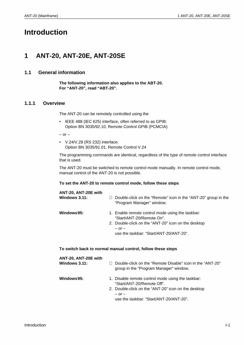
ANT-20 (Mainframe) 1 ANT-20, ANT-20E, ANT-20SE
Introduction
1 ANT-20, ANT-20E, ANT-20SE
1.1 General information
The following information also applies to the ABT-20.For “ANT-20”, read “ABT-20”.
1.1.1 Overview
The ANT-20 can be remotely controlled using the
• IEEE 488 (IEC 625) interface, often referred to as GPIB: Option BN 3035/92.10, Remote Control GPIB (PCMCIA)
– or –
• V.24/V.28 (RS 232) interface:Option BN 3035/91.01, Remote Control V.24
The programming commands are identical, regardless of the type of remote control interface that is used.
The ANT-20 must be switched to remote control mode manually. In remote control mode, manual control of the ANT-20 is not possible.
To set the ANT-20 to remote control mode, follow these steps
To switch back to normal manual control, follow these steps
ANT-20, ANT-20E with Windows 3.11: ⇒ Double-click on the “Remote” icon in the “ANT-20” group in the
“Program Manager” window.
Windows95: 1. Enable remote control mode using the taskbar: “Start/ANT-20/Remote On”.
2. Double-click on the “ANT-20” icon on the desktop – or –use the taskbar: “Start/ANT-20/ANT-20”.
ANT-20, ANT-20E with Windows 3.11: ⇒ Double-click on the “Remote Disable” icon in the “ANT-20”
group in the “Program Manager” window.
Windows95: 1. Disable remote control mode using the taskbar: “Start/ANT-20/Remote Off”.
2. Double-click on the “ANT-20” icon on the desktop – or –use the taskbar: “Start/ANT-20/ANT-20”.
Introduction I-1
1 ANT-20, ANT-20E, ANT-20SE ANT-20 (Mainframe)
From the viewpoint of remote control, each measuring module in the ANT-20 is a fully remote-controllable instrument with its own SCPI command tree, status reporting system and common command set.
The measuring module to be controlled is selected using the commandMODule:SELect <module_name> (see Sec. 1.1.2).
The instrument’s display shows which measuring modules exist and which one is selected for remote control.
A built-in monitor function can be switched on for debugging purposes (see Sec. 1.1.3).
To change the type of the remote control interface and/or its accompanying configuration parameters, the batch file remote.bat must be edited.
1.1.2 Module selection
The remote control interface of the ANT-20 supports multiple internal measuring modules. The module selection provides a mechanism to select one of these measuring modules for remote control.
This command selects the measuring module specified by <module_name> for remote control and deselects all others. All subsequent commands (including commands in subsequent program messages) are passed to the selected measuring module. All other measuring modules are unavailable for programming until selected.
<module_name>:
ANT-20, ANT-20E with Windows 3.11: 1. Double-click on the “Remote Configuration” icon in the
“ANT-20” group in the “Program Manager” window to edit the remote.bat file.
2. Follow the on-screen instructions.
Windows95: 1. Click on the “Remote Configuration” icon via taskbar: “Start/ANT-20/Remote Configuration” to edit the remote.bat file.
2. Follow the on-screen instructions.
Keyword Parameter form Notes
MODule:SELect <module_name> 1 [no query]
1 <module_name>: BASIC | JITTER | JITT16 | BAG
Table I-1 Module selection
BASIC: Selects BASIC ModuleJITTER: Selects JITTER Module for bit rates up to STM4/OC12 (extension slot)
(not available for ABT-20)JITT16: Selects JITTER Module for bit rates of STM16/OC48 (extension slot)
(not available for ABT-20)BAG: Selects BAG Module (Broadband Analyzer/Generator)
Note: • This command has no query form.• After power-on, the BASIC measuring module is selected.• If the MODule:SELect <module_name> command is required in a program
message, it must be the first (or the only) command in that program message.
I-2 Introduction
ANT-20 (Mainframe) 1 ANT-20, ANT-20E, ANT-20SE
1.1.3 Monitor mode
A monitor function can be switched on or off in remote control mode. If it is switched on, the instrument displays all messages sent to and from the instrument, corresponding to each operating step performed.
1.1.4 LabWindows/CVI driver
A LabWindows/CVI instrument driver is available for each measuring module.
Instrument drivers reduce application program development time and simplify instrument control by eliminating the need to learn the complex programming commands for each measuring module.
1.2 GPIB Remote Control interface
This section describes the GPIB Remote Control interface for applications using the ANT-20 as a remote controlled instrument.
Other applications using the ANT-20 as a GPIB controller for controlling external instruments are also possible (e.g. running the WG CATS Test Executive BN 3045 on the ANT-20 to control the ANT-20 measurement hardware plus external instruments).
To allow both these mutually exclusive operating modes to be used, the GPIB Remote Control interface and installation comprises all the software required for both operating modes.
1.2.1 Items included
The Remote Control GPIB (PCMCIA) Option BN 3035/92.10 comprises:
ANT-20, ANT-20E with Windows 3.11: • PCMCIA GPIB card including PCMCIA to GPIB cable
(2 meters)• CardWare User’s Manual (Award Software Inc.)• Distribution disk: CardWare Version 2.0 (Award Software Inc.)• Installation disks: ANT-20 PCMCIA System (configured
CardWare 2.0), ANT-20 GPIB Remote Control (includes NI-488.2)
• ANT-20 GPIB (NI-488.2) for Windows 3.x• Operating Manual: Remote Control• Brochure “SCPI and IEEE 488, Programmer‘s Introduction”
Windows95: • PCMCIA GPIB card including PCMCIA to GPIB cable (2 meters)
• Installation disks: ANT-20 GPIB Remote Control for Windows95 (includes NI-488.2M)
• Operating Manual: Remote Control• Brochure “SCPI and IEEE 488, Programmer‘s Introduction”
Introduction I-3
1 ANT-20, ANT-20E, ANT-20SE ANT-20 (Mainframe)
1.2.2 Installation
1.2.2.1 Overview
The PCMCIA GPIB interface from National Instruments Corp. (NI) is used with the NI-488.2/NI-488.2M software for GPIB Remote Control.
For ANT-20 with Windows 3.11 only:
• The NI-488.2 software requires standardized PCMCIA system software with Socket and Card Services (version 2.0 or higher) to be installed.
• A software called CardWare (written by Award Software Inc.) is used as PCMCIA system software. It can also be used with a wide variety of other PCMCIA cards.
• The CardWare software contained on the installation disk is already configured for use with the ANT-20.
1.2.2.2 Software installation
Software installation under Windows 3.11
If you ordered the Remote Control GPIB Option BN 3035/92.10 together with your ANT-20, the required software packages are already installed on the ANT-20 and the icons “Remote”, “Remote Disable” and “Remote Configuration” are shown in the “ANT-20” group in the “Program Manager” window.
If you ordered the Remote Control GPIB Option BN 3035/92.10 separately, install the software packages as follows:
Installing the PCMCIA System software
1. Start or return to Windows.2. Insert the ANT-20 PCMCIA System installation disk into drive A:.3. Choose “Run ...” from the “File” menu in the “Program Manager” window and
type the following command into the dialog box:A:\setupConfirm with “OK”.
4. After complete installation exit Windows, remove the installation disk from drive A:, and reboot the ANT-20.
Installing the GPIB Remote Control software
1. Start or return to Windows.2. Insert the ANT-20 GPIB Remote Control installation disk into drive A:.
Note: A release code is required to enable the Remote Control GPIB Option.For detailed information contact your nearest Wavetek Wandel Goltermann Service Center. The addresses are listed at the end of this manual. When contacting the Service Center, always quote:• The serial number of the ANT-20• The version number of the ANT-20 software package
I-4 Introduction
ANT-20 (Mainframe) 1 ANT-20, ANT-20E, ANT-20SE
3. Choose “Run ...” from the “File” menu in the “Program Manager” window and type the following command into the dialog box:A:\setupConfirm with “OK”.
4. After complete installation exit Windows, remove the installation disk from drive A:, and reboot the ANT-20.
Installing the ANT-20 Remote Control software
1. Start or return to Windows2. Choose “Run...” from the “File” menu in the “Program Manager” window and
type the following command into the dialog box:C:\ANT20.SUP\DISK1\setup.exeConfirm with “OK”.
3. Follow the on-screen instructions to install the ANT-20 Remote Control.4. After complete installation exit Windows, and reboot the ANT-20.
After this installation procedure, the ANT-20 can be set to remote control mode by double-clicking on the “Remote” icon in the “ANT-20” group in the “Program Manager” window.
Installing the GPIB (NI-488.2) for Windows 3.x
This software is required for applications that use the ANT-20 as a GPIB controller for controlling external instruments (e.g. for running the WG CATS Test Executive BN 3045 on the ANT-20 to control the ANT-20 measurement hardware plus external instruments).
1. Start or return to Windows.2. Insert the installation disk ANT-20 GPIB (NI-488.2) for Windows 3.x into drive A:.3. Choose “Run...” from the “File” menu in the “Program Manager” window and type the
following command into the dialog box:A:\setupConfirm with “OK”.
4. Follow the on-screen instructions to complete the installation.5. After complete installation exit Windows, remove the installation disk from drive A:, and
reboot the ANT-20.
After this installation procedure, you can access the “NI-488.2 PCMCIA GPIB Software” group in the “Program Manager” window.
To view or modify the NI-488.2 software configuration, double-click the “GPIB” icon from the “Control Panel” in the “Main” group of the “Program Manager” window.
Software installation under Windows95
If you ordered the Remote Control GPIB Option BN 3035/92.10 together with your ANT-20, the required software packages are already installed on the ANT-20 and the icons “Remote On”, “Remote Off” and “Remote Configuration” are shown in the Windows95 file folder “ANT-20”.
Verify the PCMCIA GPIB card installation as described in section “Verify the PCMCIA GPIB card installation” below.
Note: A release code is required to enable the Remote Control GPIB Option.For detailed information contact your nearest Wavetek Wandel Goltermann Service Center. The addresses are listed at the end of this manual. When contacting the Service Center, always quote:• The serial number of the ANT-20• The version number of the ANT-20 software package
Introduction I-5
1 ANT-20, ANT-20E, ANT-20SE ANT-20 (Mainframe)
If you ordered the Remote Control GPIB Option BN 3035/92.10 separately, install the software packages as follows:
Installing the GPIB Remote Control software
1. Start or return to Windows95.2. Insert the ANT-20 GPIB Remote Control for Windows95 installation disk 1 into drive A:.3. Click the Windows95 “Start” button, choose “Run ...” and
type the following command into the dialog box:A:\setupConfirm with “OK”.
4. Follow the on-screen instructions during the installation procedure and enterC:\Tmp\Gpibas GPIB distribution directory.
5. After completion, click the Windows95 “Start” button, choose “Run...” and type the following command into the dialog box:C:\Tmp\Gpib\gpib9513.exeConfirm with “OK”.
6. Follow the on-screen instructions during the setup procedure and use the default selection for components to install (all components selected).
7. After complete installation:– Shut down the ANT-20.– Remove the installation disk from drive A:.– Insert the PCMCIA GPIB card into a free PCMCIA slot.– Reboot the ANT-20.
Enable support for DOS applications as described below (by default, DOS support is disabled):
1. Return to Windows95, click the Windows95 “Start” button, choose “Settings” and then choose “Control Panel” from the submenu. In the “Control Panel” window, double-click the “System” icon.
2. In the “Device Manager” tab of the “System Properties” window, choose “View devices by type”, click on the “National Instruments GPIB Interfaces” icon in the list and then click on the “Properties” button.
3. In the “General” tab in the “National Instruments GPIB Interfaces Properties” window select the checkbox “Enable Support for DOS GPIB Applications” and confirm with “OK”.
4. Reboot the ANT-20.
Verify the PCMCIA GPIB card installation
1. The PCMCIA GPIB card must be in the slot!2. Click the Windows95 “Start” button, choose “Settings” and then
choose “Control Panel” from the submenu.In the “Control Panel” window, double-click the “System” icon.
3. In the “Device Manager” tab of the “System Properties” window,choose “View devices by type”,double-click the “National Instruments GPIB Interfaces” icon in the list and thendouble-click “PCMCIA GPIB” in the sublist.
4. In the “GPIB Settings” tab of the “PCMCIA GPIB Properties” window, the entry for“Interface Name” must be “GPIB0”. If it is not, change it to “GPIB0”.
5. Deactivate the “System Controller” checkbox.(All other parameters are properly set by starting the ANT-20 remote control mode after completion of the installation procedure.)
6. Confirm with “OK”.
I-6 Introduction
ANT-20 (Mainframe) 1 ANT-20, ANT-20E, ANT-20SE
Installing the ANT-20 Remote Control software
1. Start or return to Windows95.2. Click the Windows95 “Start” button,
choose “Run...” and type the following command into the dialog box:C:\ANT20.SUP\DISK1\setup.exeConfirm with “OK”.
3. Follow the on-screen instructions to install the ANT-20 Remote Control and select only the “Remote Control Software” as component to install.
The following patch installation described in steps 4, 5 and 6 is only required for ANT-20 software versions less or equal 7.0. It has no effect on versions greater than 7.0.
4. Insert the ANT-20 GPIB Remote Control for Windows95 installation disk 3 into drive A:.5. Click on the Windows95 “Start” button, choose “Run...” and
type the following command into the dialog box:A:\setupConfirm with “OK”.
6. Follow the on-screen instructions.After completion, remove the installation disk from drive A:.
Note: Only for ANT-20 software versions less or equal 7.0:If there is any need to execute C:\ANT20.SUP\DISK1\setup.exe (with the component “Remote Control Software” selected) at a later time again, the above described patch installation (steps 4, 5 and 6) must also be executed again.
7. Exit Windows95 and reboot the ANT-20.
After this installation procedure, you can enable the remote control mode by using the taskbar:
1. “Start/ANT-20/Remote On”.2. Then double-click on the “ANT-20” icon on the desktop or
use the taskbar: “Start/ANT-20/ANT-20”.
1.2.2.3 Hardware installation
1. Insert the PCMCIA GPIB card into a free PCMCIA socket the same way you insert a disk into a floppy drive.The PCMCIA GPIB has no jumpers or switches to set, and you do not need to power down the ANT-20 when you insert or remove the card.
2. Connect the PCMCIA GPIB cable to the PCMCIA GPIB card.
Introduction I-7
1 ANT-20, ANT-20E, ANT-20SE ANT-20 (Mainframe)
1.2.3 Connecting to GPIB
The GPIB Remote Control interface is equipped with a standard 24-way connector conforming to IEEE 488.1.
GPIB cables of various lengths are available for connecting the ANT-20 to other instruments and to the bus controller:
• 1.2 m long: Part number K 420• 2.0 m long: Part number K 421
1.2.4 Device address
Each instrument in the interface system must have a unique address to allow the controller to access each one individually.
The ANT-20 address can be changed by editing the remote.bat batch file. Any address in the range 0 to 30 can be selected.
Note: Make sure that a given address is used only once within the interface system. The controller address is reserved for the controller.
Note: • The total length of GPIB cable must not exceed 2 meters x the number of instruments in the interface system.
• Up to 15 instruments can be connected to the interface system. The maximum cable run used to connect a group of instruments is 20 meters. For more information refer to the IEEE 488.1 standard.
• Longer distances can be bridged using interface couplers (2-wire or 4-wire connections, if necessary with suitable modems).
ANT-20, ANT-20E with Windows 3.11: 1. Double-click on the “Remote Configuration” icon in the
“ANT-20” group in the “Program Manager” window to edit the remote.bat file.
2. Follow the on-screen instructions.
Windows95: 1. Click on the “Remote Configuration” icon via taskbar: “Start/ANT-20/Remote Configuration” to edit the remote.bat file.
2. Follow the on-screen instructions.
I-8 Introduction
ANT-20 (Mainframe) 1 ANT-20, ANT-20E, ANT-20SE
1.2.5 Interface functions
1.2.5.1 Overview
1.2.5.2 Device Clear
When the IEEE 488 interface message Device Clear (DCL) or Selected Device Clear (SDC) is sent to the ANT-20, a device clear message is routed to all internal measuring modules, regardless of whether they are selected or deselected.
The device clear message initializes remote control of the instrument and ensures that a subsequently sent program message will be accepted and processed.
No instrument initialization is performed by DCL or SDC. To initialize the instrument, select every measuring module and send the reset command*RST (MODule:SELect <module_name>; *RST).
1.3 V.24/V.28 (RS 232) Remote Control interface
1.3.1 Items included
The Remote Control V.24/RS 232 Option BN 3035/91.01 consists of
• Remote Control Operating Manual• Brochure “SCPI and IEEE 488, Programmer’s Introduction”
1.3.2 Installation
For remote control via RS 232 the built-in serial port (COM1) of the embedded PC-AT is used.
Interface function Note
SH1 Source Handshake Complete capability
AH1 Acceptor Handshake Complete capability
T8 Talker No Talk Only capabilityNo Serial Poll capability
L4 Listener No Listen Only capability
SR0 Service Request No capability
RL0 Remote/Local No capability
PP0 Parallel Poll No capability
DC1 Device Clear Complete capability
DT0 Device Trigger No capability
C0 Controller No capability
Table I-2 Interface functions conforming to the IEEE 488.1 standard
Introduction I-9
1 ANT-20, ANT-20E, ANT-20SE ANT-20 (Mainframe)
1.3.2.1 Software installation
Software installation under Windows 3.11
If you ordered the Remote Control V.24/V.28 (RS 232) Option BN 3035/91.01 together with your ANT-20, the required software package is already installed on the ANT-20 and the icons “Remote”, “Remote Disable” and “Remote Configuration” are shown in the “ANT-20” group in the “Program Manager” window.
If you ordered the Remote Control V.24/V.28 (RS 232) Option BN 3035/91.01 separately, install the software package as follows:
Installing the ANT-20 Remote Control software
1. Start or return to Windows2. Choose “Run...” from the “File” menu in the “Program Manager” window and
type the following command into the dialog box:C:\ANT20.SUP\DISK1\setup.exeConfirm with “OK”.
3. Follow the on-screen instructions to install the ANT-20 Remote Control.4. After complete installation exit Windows, and reboot the ANT-20.
After this installation procedure, the ANT-20 can be set to remote control mode by double-clicking on the “Remote” icon in the “ANT-20” group in the “Program Manager” window.
Software installation under Windows95
If you ordered the Remote Control V.24/V.28 (RS 232) Option BN 3035/91.01 together with your ANT-20, the required software package is already installed on the ANT-20 and the icons “Remote On”, “Remote Off” and “Remote Configuration” are shown in the Windows95 file folder “ANT-20”.
Note: A release code is required to enable the Remote Control V.24/V.28 (RS 232) Option.For detailed information contact your nearest Wavetek Wandel Goltermann Service Center. The addresses are listed at the end of this manual. When contacting the Service Center, always quote:• The serial number of the ANT-20• The version number of the ANT-20 software package
Note: A release code is required to enable the Remote Control V.24/V.28 (RS 232) Option.For detailed information contact your nearest Wavetek Wandel Goltermann Service Center. The addresses are listed at the end of this manual. When contacting the Service Center, always quote:• The serial number of the ANT-20• The version number of the ANT-20 software package
I-10 Introduction
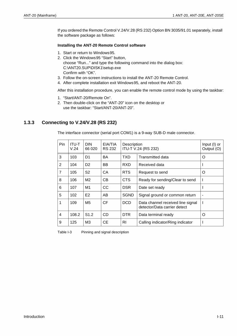
ANT-20 (Mainframe) 1 ANT-20, ANT-20E, ANT-20SE
If you ordered the Remote Control V.24/V.28 (RS 232) Option BN 3035/91.01 separately, install the software package as follows:
Installing the ANT-20 Remote Control software
1. Start or return to Windows95.2. Click the Windows95 “Start” button,
choose “Run...” and type the following command into the dialog box:C:\ANT20.SUP\DISK1\setup.exeConfirm with “OK”.
3. Follow the on-screen instructions to install the ANT-20 Remote Control.4. After complete installation exit Windows95, and reboot the ANT-20.
After this installation procedure, you can enable the remote control mode by using the taskbar:
1. “Start/ANT-20/Remote On”.2. Then double-click on the “ANT-20” icon on the desktop or
use the taskbar: “Start/ANT-20/ANT-20”.
1.3.3 Connecting to V.24/V.28 (RS 232)
The interface connector (serial port COM1) is a 9-way SUB-D male connector.
Pin ITU-TV.24
DIN66 020
EIA/TIARS 232
DescriptionITU-T V.24 (RS 232)
Input (I) orOutput (O)
3 103 D1 BA TXD Transmitted data O
2 104 D2 BB RXD Received data I
7 105 S2 CA RTS Request to send O
8 106 M2 CB CTS Ready for sending/Clear to send I
6 107 M1 CC DSR Date set ready I
5 102 E2 AB SGND Signal ground or common return -
1 109 M5 CF DCD Data channel received line signal detector/Data carrier detect
I
4 108.2 S1.2 CD DTR Data terminal ready O
9 125 M3 CE RI Calling indicator/Ring indicator I
Table I-3 Pinning and signal description
Introduction I-11
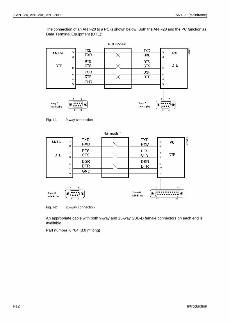
1 ANT-20, ANT-20E, ANT-20SE ANT-20 (Mainframe)
The connection of an ANT-20 to a PC is shown below. Both the ANT-20 and the PC function as Data Terminal Equipment (DTE):
Fig. I-1 9-way connection
Fig. I-2 25-way connection
An appropriate cable with both 9-way and 25-way SUB-D female connectors on each end is available:
Part number K 764 (3.0 m long)
I-12 Introduction
ANT-20 (Mainframe) 1 ANT-20, ANT-20E, ANT-20SE
1.3.4 Transmission parameters
The baud rate can be changed by editing the remote.bat batch file.
The following baud rates can be selected:
• 1200 bit/s• 2400 bit/s• 4800 bit/s• 9600 bit/s• 19200 bit/s• 38400 bit/s• 57600 bit/s
The interface operates in full-duplex (FDX) mode.
The other transmission parameters are fixed and cannot be changed:
ANT-20, ANT-20E with Windows 3.11: 1. Double-click on the “Remote Configuration” icon in the
“ANT-20” group in the “Program Manager” window to edit the remote.bat file.
2. Follow the on-screen instructions.
Windows95: 1. Click on the “Remote Configuration” icon via taskbar: “Start/ANT-20/Remote Configuration” to edit the remote.bat file.
2. Follow the on-screen instructions.
Parameter Setting
Parity None
Number of stop bits per character 1
Number of data bits per character 8
Flow control Hardware handshake by control lines RTS/CTS
Table I-4 Fixed V.24/RS 232 Transmission parameters
Introduction I-13
1 ANT-20, ANT-20E, ANT-20SE ANT-20 (Mainframe)
1.3.5 Interface functions
1.3.5.1 Overview
There is no functional equivalence to the GPIB interface functions Service Request and Serial Poll.
However, the GPIB interface function Device Clear is simulated by a BREAK signal(see Sec. 1.3.5.2, Page I-14).
1.3.5.2 Device Clear
When the BREAK signal is sent to the ANT-20, a device clear message is routed to all internal measuring modules, regardless of whether they are selected or deselected.
BREAK is detected when the RXD input is at positive voltage (i.e. logical 0 or SPACE) for the entire character frame including the stop bit.
The device clear message initializes remote control of the instrument and ensures that a subsequently sent program message will be accepted and processed.
No instrument initialization is performed by the device clear message.
To initialize the instrument, select every measuring module and send the reset command *RST(MODule:SELect <module_name>; *RST).
I-14 Introduction
ANT-20 (Mainframe) 2 DominoCOM ANT-20
2 DominoCOM ANT-20
2.1 General information
2.1.1 Items included
The delivery includes the following items relating to remote control:
• PCMCIA GPIB card including PCMCIA to GPIB cable (2 meters)• Configuration disk: DominoCOM ANT-20 Remote Control• Remote Control Operating Manual• Brochure “SCPI and IEEE 488, Programmer‘s Introduction”
For DominoCOM ANT-20 with Windows 3.11 only:
• CardWare User´s Manual (Award Software Inc.)• Distribution disk: CardWare Version 2.0 (Award Software Inc.)
2.1.2 Overview
The DominoCOM ANT-20 can be remotely controlled using the
• IEEE 488 (IEC 625) interface, often referred to as GPIB
– or –
• V.24/V.28 (RS 232) interface
The programming commands are identical, regardless of the type of remote control interface that is used.
From the viewpoint of remote control, each measuring module in the DominoCOM ANT-20 is a fully remote-controllable instrument with its own SCPI command tree, status reporting system and common command set.
The measuring module to be controlled is selected using the commandMODule:SELect <module_name> (see Sec. 2.1.5, Page I-17).
Refer to Sec. 2.1.3, Page I-15 for changing the type of remote control interface and/or its accompanying configuration parameters.
DominoCOM ANT-20 can operate in the ANT-20 mode with the use of an external monitor, keyboard and mouse. Refer to Sec. 2.1.4, Page I-16, for detailed information.
2.1.3 Changing the configuration
To change the type of remote control interface and/or its accompanying configuration parameters, follow these steps
1. Edit the remote.bat batch file (on the configuration disk) by using an external PC.Refer to the readme.txt file (on the configuration disk) for detailed editing information.
2. Insert the configuration disk into drive A: of the DominoCOM ANT-20 and reboot the DominoCOM ANT-20 (switch power off, then power on).
Factory-set configuration: Interface type V.24/V.28 (RS 232)Baud rate 9600 bit/s
Introduction I-15
2 DominoCOM ANT-20 ANT-20 (Mainframe)
2.1.4 ANT-20 mode
By connecting an external monitor, keyboard and mouse to the embedded PC-AT, the DominoCOM ANT-20 can be operated in the same way as an ANT-20.
The display shows which measuring modules exist and which one is selected for remote control.
A monitor function can be switched on for debugging purposes during remote control mode that displays all messages sent to and from the DominoCOM ANT-20, corresponding to each operating step performed.
Edit the remote.bat batch file (for changing the type of the remote control interface and/or its accompanying configuration parameters) as follows:
To leave remote control mode and enter normal manual control, follow these steps
To switch back to remote control mode, follow these steps
DominoCOM ANT-20 with Windows 3.11: 1. Double-click on the “Remote Configuration” icon in the “ANT-20”
group in the “Program Manager” window. 2. Follow the on-screen instructions.
Windows95: 1. Click on the “Remote Configuration” icon via taskbar: “Start/ANT-20/Remote Configuration”.
2. Follow the on-screen instructions.
DominoCOM ANT-20 with Windows 3.11: ⇒ Double-click on the “Remote Disable” icon in the “ANT-20”
group in the “Program Manager” window.
Windows95: 1. Disable remote mode using the taskbar: “Start/ANT-20/Remote Off”.
2. Then double-click on the “ANT-20” icon on the desktop or use the taskbar: “Start/ANT-20/ANT-20”.
DominoCOM ANT-20 with Windows 3.11: ⇒ Double-click on the “Remote” icon in the “ANT-20” group in the
“Program Manager” window.
Windows95: 1. Enable remote mode using the taskbar: “Start/ANT-20/Remote On”.
2. Then double-click on the “ANT-20” icon on the desktop or use the taskbar: “Start/ANT-20/ANT-20”.
I-16 Introduction
ANT-20 (Mainframe) 2 DominoCOM ANT-20
2.1.5 Module selection
The remote control interface of the DominoCOM ANT-20 supports multiple internal measuring modules. The module selection provides a mechanism to select one of these measuring modules for remote control.
This command selects the measuring module specified by <module_name> for remote control and deselects all others. All subsequent commands (including commands in subsequent program messages) are passed to the selected measuring module. All other measuring modules are unavailable for programming until selected.
<module_name>:
2.1.6 LabWindows/CVI driver
A LabWindows/CVI instrument driver is available for each measuring module.
Instrument drivers reduce application program development time and simplify instrument control by eliminating the need to learn the complex programming commands for each measuring module.
2.2 GPIB Remote Control interface
This section describes the GPIB Remote Control interface for applications using the DominoCOM ANT-20 as a remote controlled instrument.
Applications using the DominoCOM ANT-20 as a GPIB Controller for controlling external instruments are also possible (e.g. running the WG CATS Test Executive BN 3045 on the DominoCOM ANT-20 to control the DominoCOM ANT-20 measurement hardware plus external instruments).
To allow both these mutually exclusive operating modes to be used, the GPIB Remote Control interface and installation comprises all the software required for both operating modes.
Keyword Parameter form Notes
MODule:SELect <module_name>1 [no query]
1 <module_name>: BASIC | JITTER | JITT16 | BAG
Table I-5 Module selection
BASIC: Selects BASIC ModuleJITTER: Selects JITTER Module for bit rates up to STM4/OC12 (extension slot)
(not available for ABT-20)JITT16: Selects JITTER Module for bit rates of STM16/OC48 (extension slot)
(not available for ABT-20)BAG: Selects BAG Module (Broadband Analyzer/Generator)
Note: • This command has no query form.• After power-on, the BASIC measuring module is selected.• If the MODule:SELect <module_name> command is required in a program
message, it must be the first (or the only) command in that program message.
Introduction I-17
2 DominoCOM ANT-20 ANT-20 (Mainframe)
2.2.1 Installation
2.2.1.1 Overview
The PCMCIA GPIB interface from National Instruments Corp. (NI) is used with the NI-488.2/NI-488.2M software for GPIB Remote Control. This software is already installed on the DominoCOM ANT-20.
For DominoCOM ANT-20 with Windows 3.11 only:
• The NI-488.2 software requires standardized PCMCIA system software with Socket and Card Services (version 2.0 or higher) to be installed.
• A software called CardWare (written by Award Software Inc.) is used as PCMCIA system software. It can also be used with a wide variety of other PCMCIA cards.
• The CardWare software is already installed on the DominoCOM ANT-20 and suitably configured.
2.2.1.2 Configuration for GPIB
Set the configuration parameters:
• Interface type GPIB• Device address
by editing the remote.bat batch file.Refer to Sec. 2.1.3, Page I-15, for detailed information.
Each instrument in the interface system must have an unique address to allow the controller to access each one individually.
Any address in the range 0 to 30 can be selected.
Note: Make sure that a given address is used only once within the interface system. The controller address is reserved for the controller.
2.2.1.3 Hardware installation
1. Insert the PCMCIA GPIB card into a free PCMCIA socket the same way you insert a disk into a floppy drive.The PCMCIA GPIB has no jumpers or switches to set, and you do not need to power down the DominoCOM ANT-20 when you insert or remove the card.
2. Connect the PCMCIA GPIB cable to the PCMCIA GPIB card.
I-18 Introduction
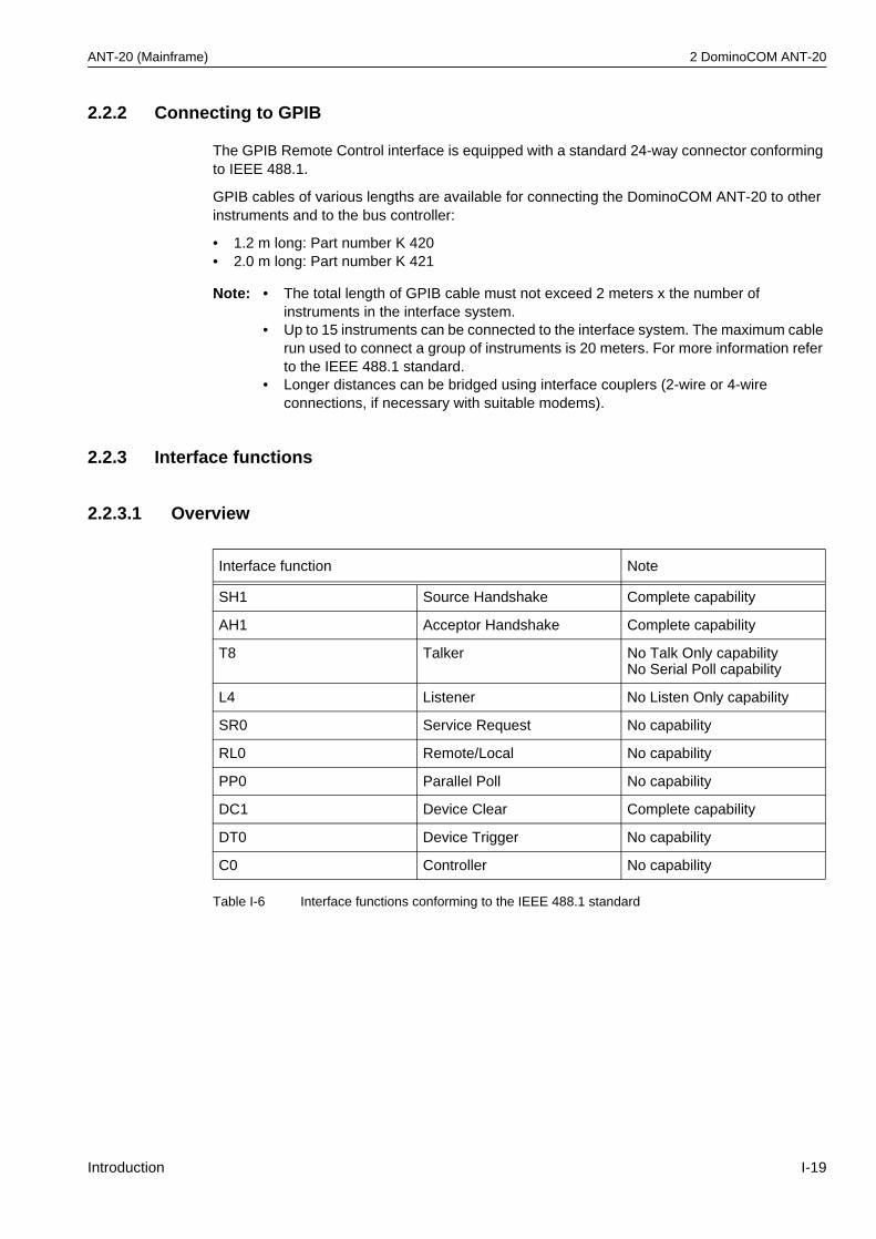
ANT-20 (Mainframe) 2 DominoCOM ANT-20
2.2.2 Connecting to GPIB
The GPIB Remote Control interface is equipped with a standard 24-way connector conforming to IEEE 488.1.
GPIB cables of various lengths are available for connecting the DominoCOM ANT-20 to other instruments and to the bus controller:
• 1.2 m long: Part number K 420• 2.0 m long: Part number K 421
2.2.3 Interface functions
2.2.3.1 Overview
Note: • The total length of GPIB cable must not exceed 2 meters x the number of instruments in the interface system.
• Up to 15 instruments can be connected to the interface system. The maximum cable run used to connect a group of instruments is 20 meters. For more information refer to the IEEE 488.1 standard.
• Longer distances can be bridged using interface couplers (2-wire or 4-wire connections, if necessary with suitable modems).
Interface function Note
SH1 Source Handshake Complete capability
AH1 Acceptor Handshake Complete capability
T8 Talker No Talk Only capabilityNo Serial Poll capability
L4 Listener No Listen Only capability
SR0 Service Request No capability
RL0 Remote/Local No capability
PP0 Parallel Poll No capability
DC1 Device Clear Complete capability
DT0 Device Trigger No capability
C0 Controller No capability
Table I-6 Interface functions conforming to the IEEE 488.1 standard
Introduction I-19
2 DominoCOM ANT-20 ANT-20 (Mainframe)
2.2.3.2 Device Clear
When the IEEE 488 interface message Device Clear (DCL) or Selected Device Clear (SDC) is sent to the DominoCOM ANT-20, a device clear message is routed to all internal measuring modules, regardless of whether they are selected or deselected.
The device clear message initializes remote control of the instrument and ensures that a subsequently sent program message will be accepted and processed.
No instrument initialization is performed by DCL or SDC.
To initialize the instrument, select every measuring module and send the reset command*RST (MODule:SELect <module_name>; *RST).
I-20 Introduction
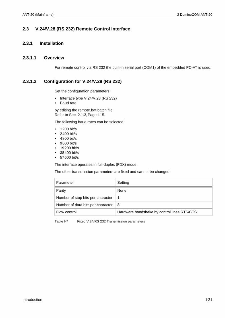
ANT-20 (Mainframe) 2 DominoCOM ANT-20
2.3 V.24/V.28 (RS 232) Remote Control interface
2.3.1 Installation
2.3.1.1 Overview
For remote control via RS 232 the built-in serial port (COM1) of the embedded PC-AT is used.
2.3.1.2 Configuration for V.24/V.28 (RS 232)
Set the configuration parameters:
• Interface type V.24/V.28 (RS 232)• Baud rate
by editing the remote.bat batch file.Refer to Sec. 2.1.3, Page I-15.
The following baud rates can be selected:
• 1200 bit/s• 2400 bit/s• 4800 bit/s• 9600 bit/s• 19200 bit/s• 38400 bit/s• 57600 bit/s
The interface operates in full-duplex (FDX) mode.
The other transmission parameters are fixed and cannot be changed:
Parameter Setting
Parity None
Number of stop bits per character 1
Number of data bits per character 8
Flow control Hardware handshake by control lines RTS/CTS
Table I-7 Fixed V.24/RS 232 Transmission parameters
Introduction I-21
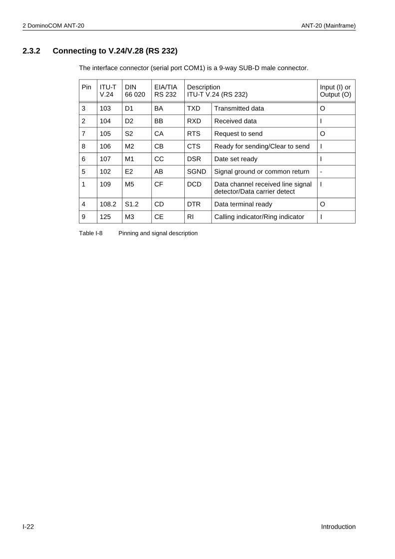
2 DominoCOM ANT-20 ANT-20 (Mainframe)
2.3.2 Connecting to V.24/V.28 (RS 232)
The interface connector (serial port COM1) is a 9-way SUB-D male connector.
Pin ITU-TV.24
DIN66 020
EIA/TIARS 232
DescriptionITU-T V.24 (RS 232)
Input (I) orOutput (O)
3 103 D1 BA TXD Transmitted data O
2 104 D2 BB RXD Received data I
7 105 S2 CA RTS Request to send O
8 106 M2 CB CTS Ready for sending/Clear to send I
6 107 M1 CC DSR Date set ready I
5 102 E2 AB SGND Signal ground or common return -
1 109 M5 CF DCD Data channel received line signal detector/Data carrier detect
I
4 108.2 S1.2 CD DTR Data terminal ready O
9 125 M3 CE RI Calling indicator/Ring indicator I
Table I-8 Pinning and signal description
I-22 Introduction
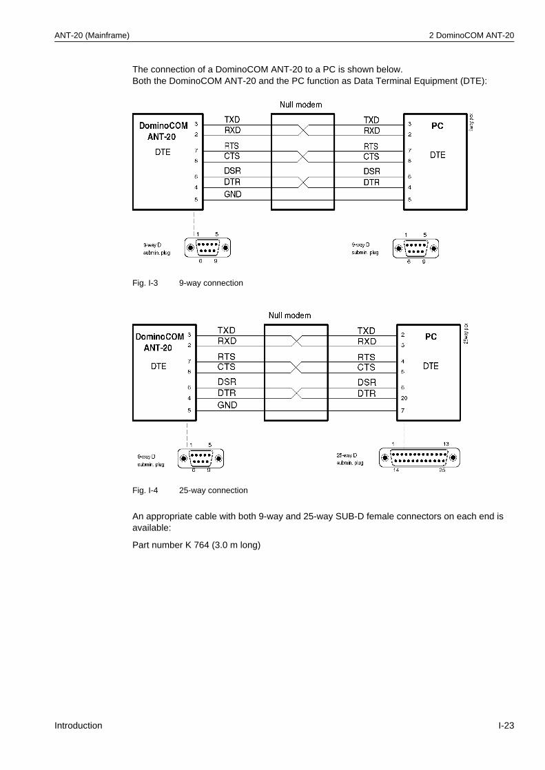
ANT-20 (Mainframe) 2 DominoCOM ANT-20
The connection of a DominoCOM ANT-20 to a PC is shown below.Both the DominoCOM ANT-20 and the PC function as Data Terminal Equipment (DTE):
Fig. I-3 9-way connection
Fig. I-4 25-way connection
An appropriate cable with both 9-way and 25-way SUB-D female connectors on each end is available:
Part number K 764 (3.0 m long)
Introduction I-23
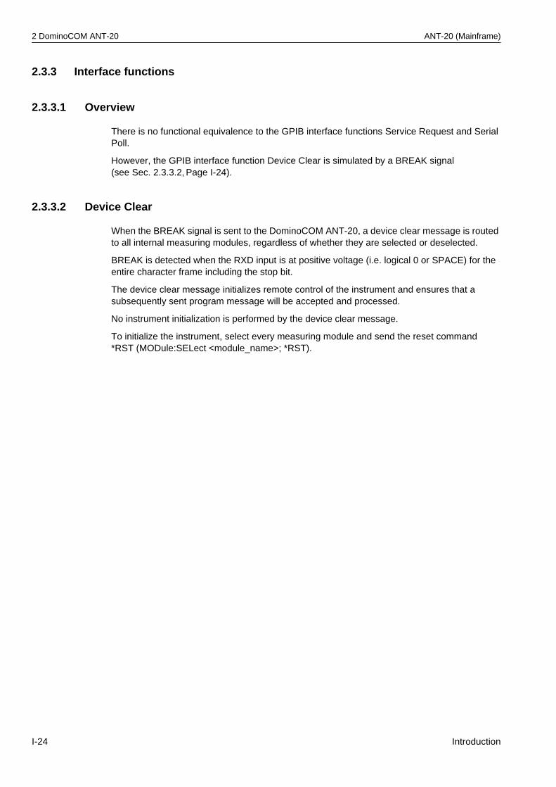
2 DominoCOM ANT-20 ANT-20 (Mainframe)
2.3.3 Interface functions
2.3.3.1 Overview
There is no functional equivalence to the GPIB interface functions Service Request and Serial Poll.
However, the GPIB interface function Device Clear is simulated by a BREAK signal(see Sec. 2.3.3.2, Page I-24).
2.3.3.2 Device Clear
When the BREAK signal is sent to the DominoCOM ANT-20, a device clear message is routed to all internal measuring modules, regardless of whether they are selected or deselected.
BREAK is detected when the RXD input is at positive voltage (i.e. logical 0 or SPACE) for the entire character frame including the stop bit.
The device clear message initializes remote control of the instrument and ensures that a subsequently sent program message will be accepted and processed.
No instrument initialization is performed by the device clear message.
To initialize the instrument, select every measuring module and send the reset command*RST (MODule:SELect <module_name>; *RST).
I-24 Introduction
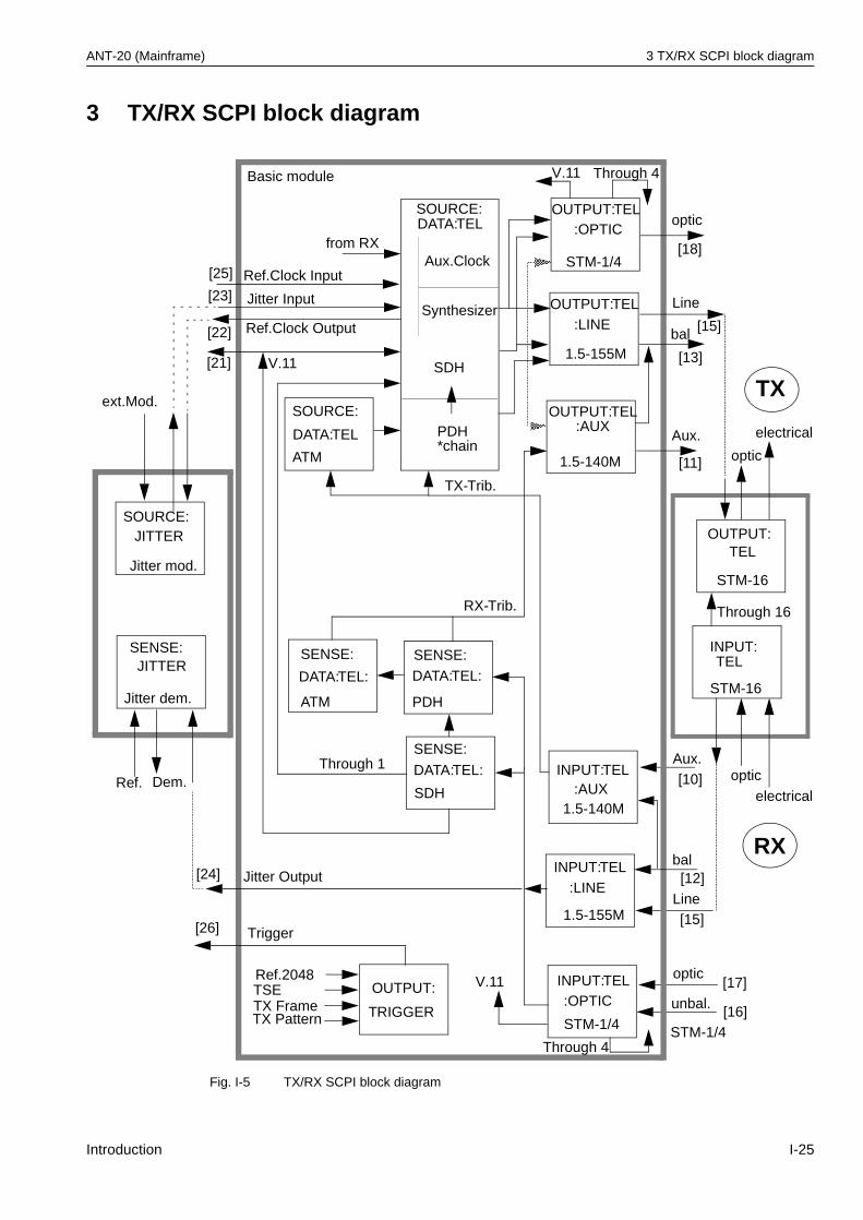
ANT-20 (Mainframe) 3 TX/RX SCPI block diagram
3 TX/RX SCPI block diagram
Fig. I-5 TX/RX SCPI block diagram
OUTPUT:TEL
OUTPUT:TEL
OUTPUT:TEL
OUTPUT:
SOURCE:DATA:TEL
:AUX
:OPTIC
:LINE
TEL
STM-16
STM-1/4
1.5-155M
1.5-140M
Line
bal
optic
optic
SDH
Synthesizer
SOURCE:JITTER
SOURCE:
DATA:TEL PDH
INPUT:TEL
:AUX
1.5-155M
INPUT:TEL
:OPTIC
1.5-140M
INPUT:TEL
:LINE
STM-1/4
INPUT:TEL
STM-16
SENSE:
DATA:TEL:
SDH
SENSE:DATA:TEL:
PDH
ATM
SENSE:JITTER
OUTPUT:
TRIGGERunbal.
bal
Trigger
optic
optic
Aux.Clock
Jitter mod.
TX-Trib.
Jitter dem.
ext.Mod.
Dem.
TX
RX
Ref.
Through 16
Ref.2048
Through 1
Jitter Input
V.11Basic module
Ref.Clock Input
from RX
RX-Trib.
SENSE:
DATA:TEL:
ATM
Jitter Output
Ref.Clock Output
V.11
V.11
[18]
[13]
[15]
[11]
[25]
[23]
Aux.
Line
Aux.*chain
Through 4
STM-1/4
[10]
[17]
[15]
[12]
[16]
Through 4
[24]
[26]
[22]
[21]
TSETX FrameTX Pattern
electrical
electrical
Introduction I-25
4 Operating information ANT-20 (Mainframe)
4 Operating information
This chapter gives the programmer some basic information which should make it easier to program this device.
• Program messages are executed in the order they are received from the controller.However, the execution of any command does not start before the PMT (Program Message Terminator <NL>) or any other sequential command is received. This gives full flexibility in controlling the device without the need to worry about the dependencies between individual commands, because the settings of coupled commands received within a single message are checked after the whole message is received.
• Commands are treated as “overlapped commands” except where otherwise noted. Overlapped commands allow the next command to be executed before the preceding command has finished execution. This gives better performance and makes it possible to change some settings while a measurement is running, for example. You can use the common command *WAI to force sequential operation whenever you need to.
• Any error detected within a program message is written into the error queue. You can read entries out of the error queue using the SYST:ERR? command. Any program message is read from the input buffer and parsed as far as possible to detect potential errors. Nevertheless, the device setting may be undefined after any error.
• Queries are not allowed to have side effects. Thus, queries of commands set in the same program message will return the old command setting.
• Note that using the SCPI short form of the commands (capital letters) will reduce operational overhead and can increase your system performance.
• The input buffer size is 4096 bytes (4 kB).
• The output buffer size is 8192 bytes (8 kB). Requesting a response with more than 8192 bytes would cause a query error.
I-26 Introduction
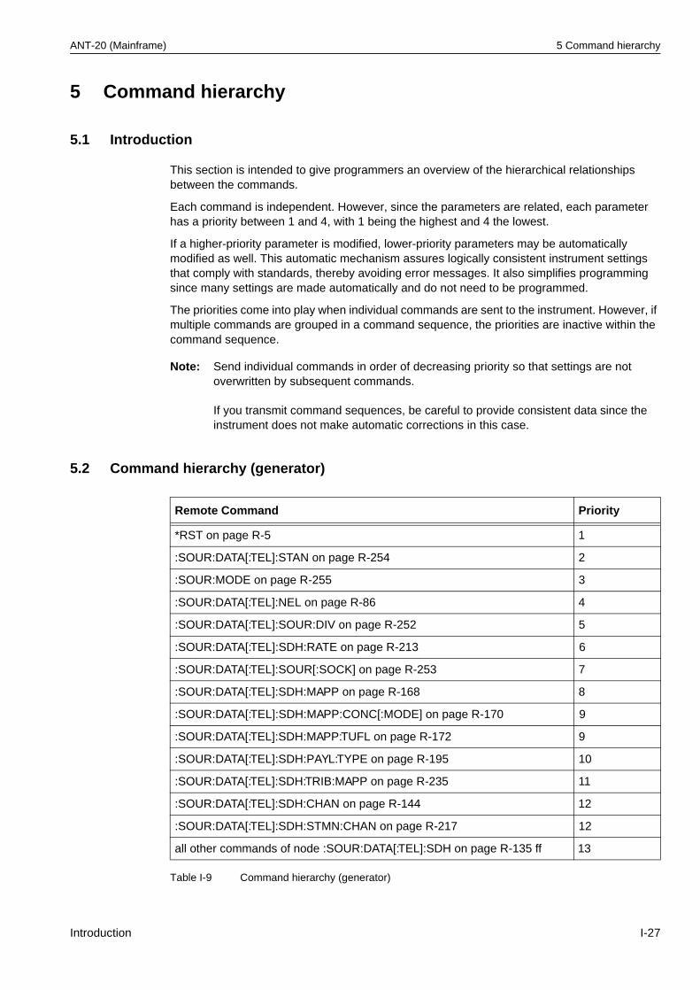
ANT-20 (Mainframe) 5 Command hierarchy
5 Command hierarchy
5.1 Introduction
This section is intended to give programmers an overview of the hierarchical relationships between the commands.
Each command is independent. However, since the parameters are related, each parameter has a priority between 1 and 4, with 1 being the highest and 4 the lowest.
If a higher-priority parameter is modified, lower-priority parameters may be automatically modified as well. This automatic mechanism assures logically consistent instrument settings that comply with standards, thereby avoiding error messages. It also simplifies programming since many settings are made automatically and do not need to be programmed.
The priorities come into play when individual commands are sent to the instrument. However, if multiple commands are grouped in a command sequence, the priorities are inactive within the command sequence.
5.2 Command hierarchy (generator)
Note: Send individual commands in order of decreasing priority so that settings are not overwritten by subsequent commands.
If you transmit command sequences, be careful to provide consistent data since the instrument does not make automatic corrections in this case.
Remote Command Priority
*RST on page R-5 1
:SOUR:DATA[:TEL]:STAN on page R-254 2
:SOUR:MODE on page R-255 3
:SOUR:DATA[:TEL]:NEL on page R-86 4
:SOUR:DATA[:TEL]:SOUR:DIV on page R-252 5
:SOUR:DATA[:TEL]:SDH:RATE on page R-213 6
:SOUR:DATA[:TEL]:SOUR[:SOCK] on page R-253 7
:SOUR:DATA[:TEL]:SDH:MAPP on page R-168 8
:SOUR:DATA[:TEL]:SDH:MAPP:CONC[:MODE] on page R-170 9
:SOUR:DATA[:TEL]:SDH:MAPP:TUFL on page R-172 9
:SOUR:DATA[:TEL]:SDH:PAYL:TYPE on page R-195 10
:SOUR:DATA[:TEL]:SDH:TRIB:MAPP on page R-235 11
:SOUR:DATA[:TEL]:SDH:CHAN on page R-144 12
:SOUR:DATA[:TEL]:SDH:STMN:CHAN on page R-217 12
all other commands of node :SOUR:DATA[:TEL]:SDH on page R-135 ff 13
Table I-9 Command hierarchy (generator)
Introduction I-27
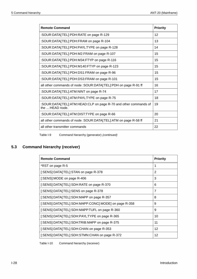
5 Command hierarchy ANT-20 (Mainframe)
5.3 Command hierarchy (receiver)
:SOUR:DATA[:TEL]:PDH:RATE on page R-129 12
:SOUR:DATA[:TEL]:PDH:FRAM on page R-104 13
:SOUR:DATA[:TEL]:PDH:PAYL:TYPE on page R-128 14
:SOUR:DATA[:TEL]:PDH:M2:FRAM on page R-107 15
:SOUR:DATA[:TEL]:PDH:M34:FTYP on page R-116 15
:SOUR:DATA[:TEL]:PDH:M140:FTYP on page R-123 15
:SOUR:DATA[:TEL]:PDH:DS1:FRAM on page R-96 15
:SOUR:DATA[:TEL]:PDH:DS3:FRAM on page R-101 15
all other commands of node :SOUR:DATA[:TEL]:PDH on page R-91 ff 16
:SOUR:DATA[:TEL]:ATM:NINT on page R-74 17
:SOUR:DATA[:TEL]:ATM:PAYL:TYPE on page R-75 18
:SOUR:DATA[:TEL]:ATM:HEAD:CLP on page R-70 and other commands of the ...:HEAD node.
19
:SOUR:DATA[:TEL]:ATM:DIST:TYPE on page R-66 20
all other commands of node :SOUR:DATA[:TEL]:ATM on page R-58 ff 21
all other transmitter commands 22
Remote Command Priority
Table I-9 Command hierarchy (generator) (continued)
Remote Command Priority
*RST on page R-5 1
[:SENS]:DATA[:TEL]:STAN on page R-378 2
[:SENS]:MODE on page R-406 3
[:SENS]:DATA[:TEL]:SDH:RATE on page R-370 6
[:SENS]:DATA[:TEL]:SENS on page R-378 7
[:SENS]:DATA[:TEL]:SDH:MAPP on page R-357 8
[:SENS]:DATA[:TEL]:SDH:MAPP:CONC[:MODE] on page R-358 9
[:SENS]:DATA[:TEL]:SDH:MAPP:TUFL on page R-360 9
[:SENS]:DATA[:TEL]:SDH:PAYL:TYPE on page R-365 10
[:SENS]:DATA[:TEL]:SDH:TRIB:MAPP on page R-375 11
[:SENS]:DATA[:TEL]:SDH:CHAN on page R-353 12
[:SENS]:DATA[:TEL]:SDH:STMN:CHAN on page R-372 12
Table I-10 Command hierarchy (receiver)
I-28 Introduction
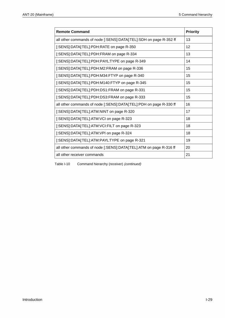
ANT-20 (Mainframe) 5 Command hierarchy
all other commands of node [:SENS]:DATA[:TEL]:SDH on page R-352 ff 13
[:SENS]:DATA[:TEL]:PDH:RATE on page R-350 12
[:SENS]:DATA[:TEL]:PDH:FRAM on page R-334 13
[:SENS]:DATA[:TEL]:PDH:PAYL:TYPE on page R-349 14
[:SENS]:DATA[:TEL]:PDH:M2:FRAM on page R-336 15
[:SENS]:DATA[:TEL]:PDH:M34:FTYP on page R-340 15
[:SENS]:DATA[:TEL]:PDH:M140:FTYP on page R-345 15
[:SENS]:DATA[:TEL]:PDH:DS1:FRAM on page R-331 15
[:SENS]:DATA[:TEL]:PDH:DS3:FRAM on page R-333 15
all other commands of node [:SENS]:DATA[:TEL]:PDH on page R-330 ff 16
[:SENS]:DATA[:TEL]:ATM:NINT on page R-320 17
[:SENS]:DATA[:TEL]:ATM:VCI on page R-323 18
[:SENS]:DATA[:TEL]:ATM:VCI:FILT on page R-323 18
[:SENS]:DATA[:TEL]:ATM:VPI on page R-324 18
[:SENS]:DATA[:TEL]:ATM:PAYL:TYPE on page R-321 19
all other commands of node [:SENS]:DATA[:TEL]:ATM on page R-316 ff 20
all other receiver commands 21
Remote Command Priority
Table I-10 Command hierarchy (receiver) (continued)
Introduction I-29
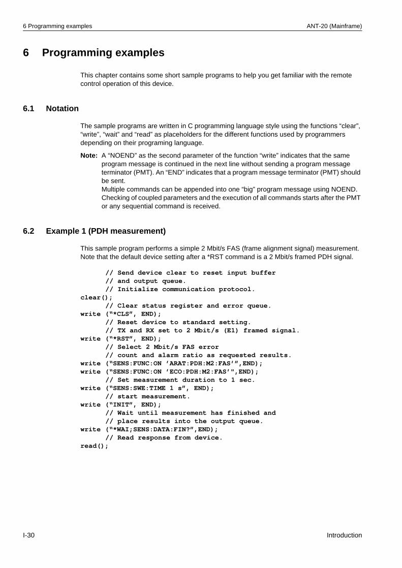
6 Programming examples ANT-20 (Mainframe)
6 Programming examples
This chapter contains some short sample programs to help you get familiar with the remote control operation of this device.
6.1 Notation
The sample programs are written in C programming language style using the functions “clear”, “write”, “wait” and “read” as placeholders for the different functions used by programmers depending on their programing language.
Note: A “NOEND” as the second parameter of the function “write” indicates that the same program message is continued in the next line without sending a program message terminator (PMT). An “END” indicates that a program message terminator (PMT) should be sent. Multiple commands can be appended into one “big” program message using NOEND. Checking of coupled parameters and the execution of all commands starts after the PMT or any sequential command is received.
6.2 Example 1 (PDH measurement)
This sample program performs a simple 2 Mbit/s FAS (frame alignment signal) measurement. Note that the default device setting after a *RST command is a 2 Mbit/s framed PDH signal.
// Send device clear to reset input buffer// and output queue.// Initialize communication protocol.
clear();// Clear status register and error queue.
write (“*CLS”, END);// Reset device to standard setting.// TX and RX set to 2 Mbit/s (E1) framed signal.
write (“*RST”, END);// Select 2 Mbit/s FAS error// count and alarm ratio as requested results.
write (“SENS:FUNC:ON ’ARAT:PDH:M2:FAS’”,END);write (“SENS:FUNC:ON ’ECO:PDH:M2:FAS’",END);
// Set measurement duration to 1 sec.write (“SENS:SWE:TIME 1 s”, END);
// start measurement.write (“INIT”, END);
// Wait until measurement has finished and// place results into the output queue.
write (“*WAI;SENS:DATA:FIN?”,END);// Read response from device.
read();
I-30 Introduction
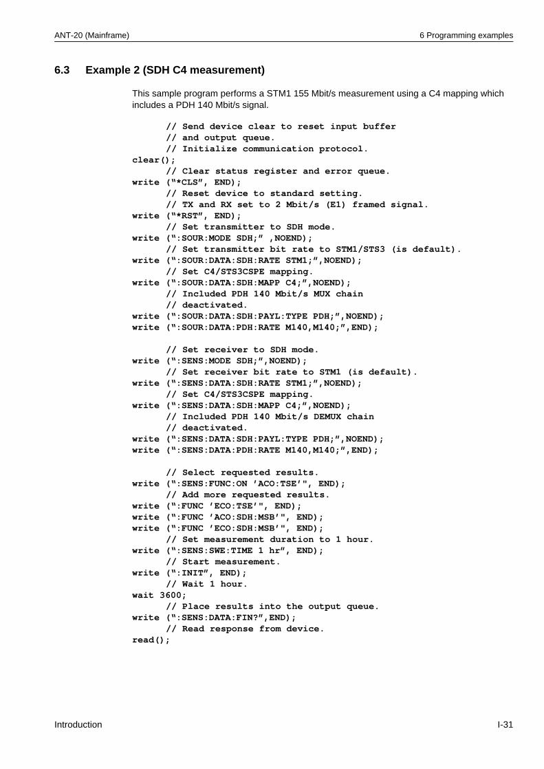
ANT-20 (Mainframe) 6 Programming examples
6.3 Example 2 (SDH C4 measurement)
This sample program performs a STM1 155 Mbit/s measurement using a C4 mapping which includes a PDH 140 Mbit/s signal.
// Send device clear to reset input buffer// and output queue.// Initialize communication protocol.
clear();// Clear status register and error queue.
write (“*CLS”, END);// Reset device to standard setting.// TX and RX set to 2 Mbit/s (E1) framed signal.
write (“*RST”, END);// Set transmitter to SDH mode.
write (“:SOUR:MODE SDH;” ,NOEND);// Set transmitter bit rate to STM1/STS3 (is default).
write (“:SOUR:DATA:SDH:RATE STM1;”,NOEND);// Set C4/STS3CSPE mapping.
write (“:SOUR:DATA:SDH:MAPP C4;”,NOEND);// Included PDH 140 Mbit/s MUX chain// deactivated.
write (“:SOUR:DATA:SDH:PAYL:TYPE PDH;”,NOEND);write (“:SOUR:DATA:PDH:RATE M140,M140;”,END);
// Set receiver to SDH mode.write (“:SENS:MODE SDH;”,NOEND);
// Set receiver bit rate to STM1 (is default).write (“:SENS:DATA:SDH:RATE STM1;”,NOEND);
// Set C4/STS3CSPE mapping.write (“:SENS:DATA:SDH:MAPP C4;”,NOEND);
// Included PDH 140 Mbit/s DEMUX chain// deactivated.
write (“:SENS:DATA:SDH:PAYL:TYPE PDH;”,NOEND);write (“:SENS:DATA:PDH:RATE M140,M140;”,END);
// Select requested results.write (“:SENS:FUNC:ON ’ACO:TSE’", END);
// Add more requested results.write (“:FUNC ’ECO:TSE’", END);write (“:FUNC ’ACO:SDH:MSB’", END);write (“:FUNC ’ECO:SDH:MSB’", END);
// Set measurement duration to 1 hour.write (“:SENS:SWE:TIME 1 hr”, END);
// Start measurement.write (“:INIT”, END);
// Wait 1 hour.wait 3600;
// Place results into the output queue.write (“:SENS:DATA:FIN?”,END);
// Read response from device.read();
Introduction I-31
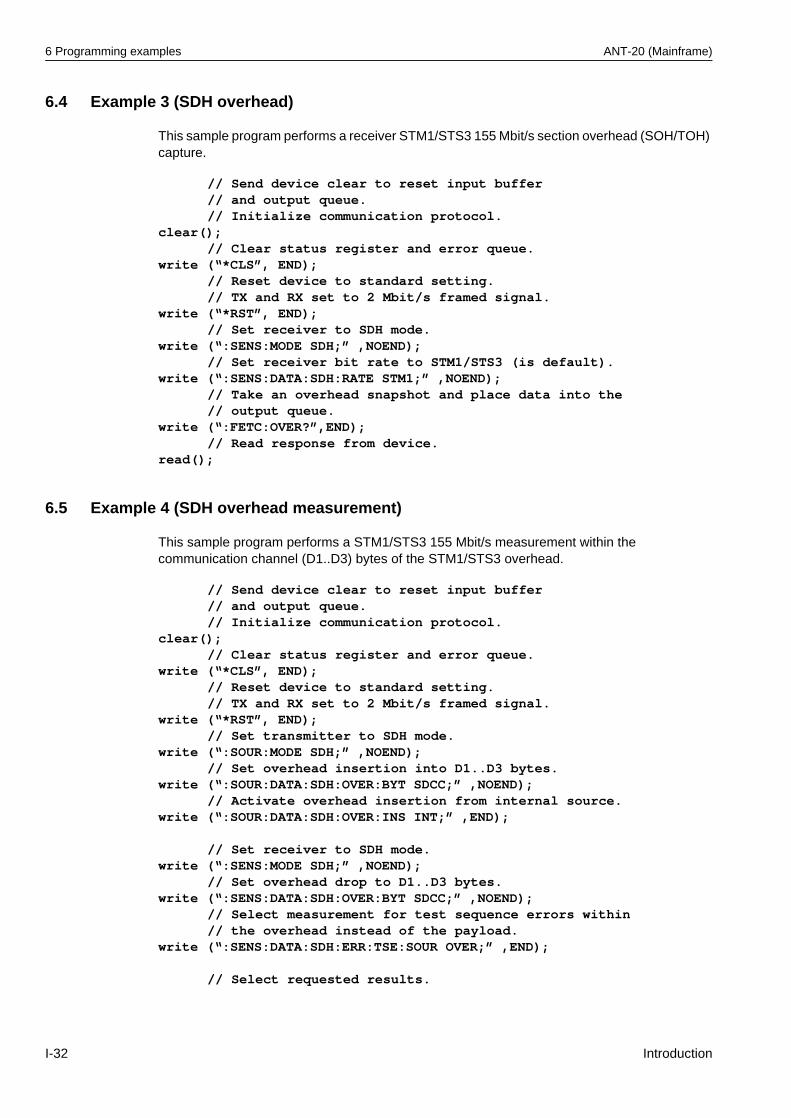
6 Programming examples ANT-20 (Mainframe)
6.4 Example 3 (SDH overhead)
This sample program performs a receiver STM1/STS3 155 Mbit/s section overhead (SOH/TOH) capture.
6.5 Example 4 (SDH overhead measurement)
This sample program performs a STM1/STS3 155 Mbit/s measurement within the communication channel (D1..D3) bytes of the STM1/STS3 overhead.
// Send device clear to reset input buffer// and output queue.// Initialize communication protocol.
clear();// Clear status register and error queue.
write (“*CLS”, END);// Reset device to standard setting.// TX and RX set to 2 Mbit/s framed signal.
write (“*RST”, END);// Set receiver to SDH mode.
write (“:SENS:MODE SDH;” ,NOEND);// Set receiver bit rate to STM1/STS3 (is default).
write (“:SENS:DATA:SDH:RATE STM1;” ,NOEND);// Take an overhead snapshot and place data into the// output queue.
write (“:FETC:OVER?”,END);// Read response from device.
read();
// Send device clear to reset input buffer// and output queue.// Initialize communication protocol.
clear();// Clear status register and error queue.
write (“*CLS”, END);// Reset device to standard setting.// TX and RX set to 2 Mbit/s framed signal.
write (“*RST”, END);// Set transmitter to SDH mode.
write (“:SOUR:MODE SDH;” ,NOEND);// Set overhead insertion into D1..D3 bytes.
write (“:SOUR:DATA:SDH:OVER:BYT SDCC;” ,NOEND);// Activate overhead insertion from internal source.
write (“:SOUR:DATA:SDH:OVER:INS INT;” ,END);
// Set receiver to SDH mode.write (“:SENS:MODE SDH;” ,NOEND);
// Set overhead drop to D1..D3 bytes.write (“:SENS:DATA:SDH:OVER:BYT SDCC;” ,NOEND);
// Select measurement for test sequence errors within// the overhead instead of the payload.
write (“:SENS:DATA:SDH:ERR:TSE:SOUR OVER;” ,END);
// Select requested results.
I-32 Introduction
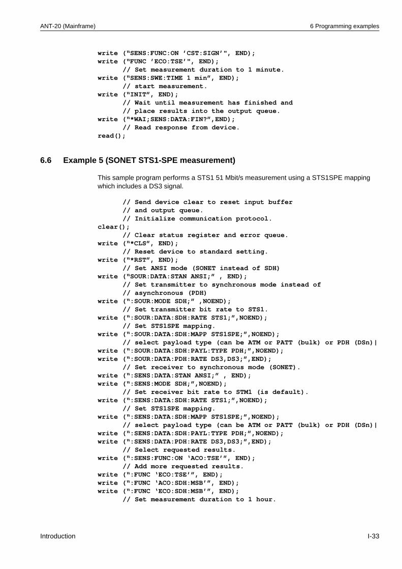
ANT-20 (Mainframe) 6 Programming examples
6.6 Example 5 (SONET STS1-SPE measurement)
This sample program performs a STS1 51 Mbit/s measurement using a STS1SPE mapping which includes a DS3 signal.
write (“SENS:FUNC:ON ’CST:SIGN’", END);write (“FUNC ’ECO:TSE’", END);
// Set measurement duration to 1 minute.write (“SENS:SWE:TIME 1 min”, END);
// start measurement.write (“INIT”, END);
// Wait until measurement has finished and// place results into the output queue.
write (“*WAI;SENS:DATA:FIN?”,END);// Read response from device.
read();
// Send device clear to reset input buffer// and output queue.// Initialize communication protocol.
clear();// Clear status register and error queue.
write (“*CLS”, END);// Reset device to standard setting.
write (“*RST”, END);// Set ANSI mode (SONET instead of SDH)
write (“SOUR:DATA:STAN ANSI;” , END);// Set transmitter to synchronous mode instead of // asynchronous (PDH)
write (“:SOUR:MODE SDH;” ,NOEND);// Set transmitter bit rate to STS1.
write (“:SOUR:DATA:SDH:RATE STS1;”,NOEND);// Set STS1SPE mapping.
write (“:SOUR:DATA:SDH:MAPP STS1SPE;”,NOEND);// select payload type (can be ATM or PATT (bulk) or PDH (DSn)|
write (“:SOUR:DATA:SDH:PAYL:TYPE PDH;”,NOEND);write (“:SOUR:DATA:PDH:RATE DS3,DS3;”,END);
// Set receiver to synchronous mode (SONET).write (“:SENS:DATA:STAN ANSI;” , END);write (“:SENS:MODE SDH;”,NOEND);
// Set receiver bit rate to STM1 (is default).write (“:SENS:DATA:SDH:RATE STS1;”,NOEND);
// Set STS1SPE mapping.write (“:SENS:DATA:SDH:MAPP STS1SPE;”,NOEND);
// select payload type (can be ATM or PATT (bulk) or PDH (DSn)|write (“:SENS:DATA:SDH:PAYL:TYPE PDH;”,NOEND);write (“:SENS:DATA:PDH:RATE DS3,DS3;”,END);
// Select requested results.write (“:SENS:FUNC:ON ‘ACO:TSE’”, END);
// Add more requested results.write (“:FUNC ‘ECO:TSE’”, END);write (“:FUNC ‘ACO:SDH:MSB’”, END);write (“:FUNC ‘ECO:SDH:MSB’”, END);
// Set measurement duration to 1 hour.
Introduction I-33
6 Programming examples ANT-20 (Mainframe)
6.7 Example 6 (SONET Transport overhead measurement)
This sample program performs a receiver STM1/STS3 155 Mbit/s Transport overhead (TOH) capture.
6.8 Example 7 (SONET DS1 ESF testing with LOF inserted)
write (“:SENS:SWE:TIME 1 hr”, END);// Start measurement.
write (“:INIT”, END);// Wait 1 hour.
wait 3600;// Place results into the output queue.
write (“:SENS:DATA:FIN?”,END);// Read response from device.
read();
// Send device clear to reset input buffer// and output queue.// Initialize communication protocol.
clear();// Clear status register and error queue.
write (“*CLS”, END);// Reset device to standard setting (E1).
write (“*RST”, END);// Set receiver to synchronous mode (SONET).
write (“:SENS:DATA:STAN ANSI;” , END);write (“:SENS:MODE SDH;” ,NOEND);
// Set receiver bit rate to STS3 (is default).write (“:SENS:DATA:SDH:RATE STS3;” ,NOEND);
// Take an overhead snapshot and place data into the// output queue.
write (“:FETC:OVER?”,END);// Read response from device.
read();
// Reset valueswrite (“*RST;”, END)write (“:func:off:all;”, END)
// Line code & framing write (“:outp:line:code B8ZS;”, NOEND)write (“:inp:line:code B8ZS;”, NOEND)write (“:sour:mode pdh;”, NOEND)write (“:sens:mode pdh;”, NOEND)write (“:sour:data:pdh:fram fram;”, NOEND)write (“:sens:data:pdh:fram fram;”, NOEND)write (“:sour:data:pdh:ds1:fram esf107;”, NOEND)write (“:sens:data:pdh:ds1:fram esf107;”, NOEND)write (“:sour:data:pdh:rate ds1, ds1;”, NOEND)write (“:sens:data:pdh:rate ds1, ds1;”, NOEND)
// Test pattern write (“:sour:data:payl:patt qrss20;”, NOEND)write (“:sens:data:payl:patt qrss20;”, END)
I-34 Introduction
ANT-20 (Mainframe) 6 Programming examples
// Insert LOFwrite (“:sour:data:pdh:alar lof1_5, cont;”, END)
// Start/Stop measurementwrite (“:sens:func ““CST:SIGN””,””CST:PDH2””,””ECO:TSE””,
””ECO:CODE””;”, END)wait 2;write (“:init;”, END)wait 3;write (“:abort;”, END)
// read and compare resultswrite (“:sens:data:act?;”, END)read();test int 50 “test status of CST:SIGN”test mask 0 245 “LOS !”test int 53 “test status of CST:PDH2 result (Defects DS1)”test mask 2 253 “Defect not LOF1.5”test int 100 “test status ECO:TSE result”test float 0 “bit error not 0”test int 130 “test status ECO:CODE result”test float 0 “BPV not 0”
Introduction I-35
7 Release Notes ANT-20 (Mainframe)
7 Release Notes
This section contains a summary of all additions included from Software Release V6.6 onwards.
7.1 New commands
Summary of all new commands included from Software Release V6.6 onwards
:SOUR:DATA[:TEL]:PDH:DS3:FEAC[:ALAR] on page R-98:SOUR:DATA[:TEL]:PDH:DS3:FEAC:LOOP[:TYPE] on page R-99:SOUR:DATA[:TEL]:PDH:DS3:FEAC:LOOP:CODE on page R-100:SOUR:DATA[:TEL]:SDH:ERR:FLEN on page R-162:SOUR:DATA[:TEL]:SDH:MAPP:OFFS on page R-169:SOUR:DATA[:TEL]:SDH:OVER:SEQ[:ACT] on page R-186:SOUR:DATA[:TEL]:SDH:OVER:SEQ:MNP:DATA on page R-187:SOUR:DATA[:TEL]:SDH:OVER:SEQ:POS:POH on page R-189:SOUR:DATA[:TEL]:SDH:OVER:SEQ:POS:SOH | TOH on page R-190:SOUR:DATA[:TEL]:SDH:OVER:SEQ:TYPE on page R-192[:SENS]:DATA[:TEL]:PDH:DS3:FEAC:LOOP:RES on page R-332[:SENS]:DATA[:TEL]:SDH:OVER:TCM:RES on page R-364:FETC:SCAL[:DATA][:TEL][:SDH]:OVER? on page R-423:FETC:STR[:DATA][:TEL][:SDH]:TCMonitoring:TRACe? on page R-432
Summary of all new commands included from Software Release V7.0 onwards
:SOUR:DATA[:TEL]:SDH:MAPP:CONC:CSIZ on page R-171:SOUR:DATA[:TEL]:SDH:POIN:SSB on page R-207:SOUR:DATA[:TEL]:SDH:OVER:SEQ:TCM:DATA on page R-191:SOUR:DATA[:TEL]:SDH:OVER:SEQ:TCM:DATA:BLOC on page R-193
:INP:CLOC:WAND[:STAT] on page R-257
[:SENS]:DATA[:TEL]:SDH:MAPP:CONC:CSIZ on page R-359
Summary of all new commands included from Software Release V7.1 onwards
:OUTP[:TEL]:OPT3[:STAT] on page R-50:SOUR:DATA[:TEL]:SDH:OVER[i]:DATA on page R-175:SOUR:DATA[:TEL]:SDH:OVER[i]:DATA:BLOC on page R-177:SOUR:DATA[:TEL]:SDH:OVER[i]:PRES on page R-179:SOUR:DATA[:TEL]:SDH:OVER[i]:RDAT on page R-182:SOUR:DATA[:TEL]:SDH:OVER[i]:RDAT:BLOC on page R-183[:SENS]:DATA[:TEL]:ANAL:M2101:ALL on page R-304[:SENS]:DATA[:TEL]:ANAL:M2101:ALL? on page R-304[:SENS]:DATA[:TEL]:ANAL:M2101:BISO:BBE? on page R-304[:SENS]:DATA[:TEL]:ANAL:M2101:BISO:ES? on page R-305[:SENS]:DATA[:TEL]:ANAL:M2101:BISO:MULT on page R-305[:SENS]:DATA[:TEL]:ANAL:M2101:BISO:MULT? on page R-305[:SENS]:DATA[:TEL]:ANAL:M2101:BISO:SEP? on page R-306[:SENS]:DATA[:TEL]:ANAL:M2101:BISO:SES? on page R-306[:SENS]:DATA[:TEL]:ANAL:M2101:EVAL on page R-306[:SENS]:DATA[:TEL]:ANAL:M2101:EVAL? on page R-307[:SENS]:DATA[:TEL]:ANAL:M2101:S1:BBE? on page R-307[:SENS]:DATA[:TEL]:ANAL:M2101:S1:ES? on page R-307[:SENS]:DATA[:TEL]:ANAL:M2101:S1:SEP? on page R-308
I-36 Introduction
ANT-20 (Mainframe) 7 Release Notes
[:SENS]:DATA[:TEL]:ANAL:M2101:S1:SES? on page R-308[:SENS]:DATA[:TEL]:ANAL:M2101:S2:BBE? on page R-308[:SENS]:DATA[:TEL]:ANAL:M2101:S2:ES? on page R-308[:SENS]:DATA[:TEL]:ANAL:M2101:S2:SEP? on page R-309[:SENS]:DATA[:TEL]:ANAL:M2101:S2:SES? on page R-309[:SENS]:DATA[:TEL]:ANAL:M2101:UAS:LIM[:STAT] on page R-310[:SENS]:DATA[:TEL]:ANAL:M2101:UAS:LIM[:STAT]? on page R-310[:SENS]:DATA[:TEL]:ANAL:M2101:UAS:LIM:UPP on page R-310[:SENS]:DATA[:TEL]:ANAL:M2101:UAS:LIM:UPP? on page R-311[:SENS]:DATA[:TEL]:ANAL:M2101:UAS:MODE on page R-311[:SENS]:DATA[:TEL]:ANAL:M2101:UAS:MODE? on page R-311[:SENS]:DATA[:TEL]:LED:AUL[:STAT] on page R-325[:SENS]:DATA[:TEL]:LED:TUL[:STAT] on page R-326:[SENS]:DATA[:TEL]:SDH:OVER:TCM:TYPE on page R-364
Summary of all new commands included from Software Release V7.2 onwards
:SOUR:DATA[:TEL]:SDH:STSN:CHAN on page R-218:SOUR:DATA[:TEL]:SDH:STSV:CHAN on page R-219[:SENS]:DATA[:TEL]:SDH:STSN:CHAN on page R-373[:SENS]:DATA[:TEL]:SDH:STSV:CHAN on page R-374[:SENS]:DATA[:TEL]:ANAL:G828:ALL on page R-291[:SENS]:DATA[:TEL]:ANAL:G828:ALL? on page R-291[:SENS]:DATA[:TEL]:ANAL:G828:EVAL on page R-291[:SENS]:DATA[:TEL]:ANAL:G828:EVAL? on page R-292[:SENS]:DATA[:TEL]:ANAL:G828:SEPI[:STAT] on page R-292[:SENS]:DATA[:TEL]:ANAL:G828:SEPI[:STAT]? on page R-292[:SENS]:DATA[:TEL]:ANAL:G828:SES:THR on page R-292[:SENS]:DATA[:TEL]:ANAL:G828:SES:THR? on page R-293[:SENS]:DATA[:TEL]:ANAL:G828:SES:THR:AUTO on page R-293[:SENS]:DATA[:TEL]:ANAL:G828:SES:THR:AUTO? on page R-293[:SENS]:DATA[:TEL]:ANAL:G828:UAS:LIM[:STAT] on page R-294[:SENS]:DATA[:TEL]:ANAL:G828:UAS:LIM[:STAT]? on page R-294[:SENS]:DATA[:TEL]:ANAL:G828:UAS:LIM:UPP on page R-294[:SENS]:DATA[:TEL]:ANAL:G828:UAS:LIM:UPP? on page R-294[:SENS]:DATA[:TEL]:ANAL:G828:UAS:MODE on page R-295[:SENS]:DATA[:TEL]:ANAL:G826:UAS:MODE? on page R-290[:SENS]:DATA[:TEL]:ANAL:G829:EVAL on page R-295[:SENS]:DATA[:TEL]:ANAL:G829:EVAL? on page R-296[:SENS]:DATA[:TEL]:ANAL:G829:SES:THR on page R-296[:SENS]:DATA[:TEL]:ANAL:G829:SES:THR? on page R-296[:SENS]:DATA[:TEL]:ANAL:G829:SES:THR:AUTO on page R-297[:SENS]:DATA[:TEL]:ANAL:G829:SES:THR:AUTO? on page R-297[:SENS]:DATA[:TEL]:ANAL:M2101:SEPI[:STAT] on page R-309[:SENS]:DATA[:TEL]:ANAL:M2101:SEPI[:STAT]? on page R-309[:SENS]:DATA[:TEL]:ANAL:M2101:VERSion on page R-311[:SENS]:DATA[:TEL]:ANAL:M2101:VERSion? on page R-312
Introduction I-37
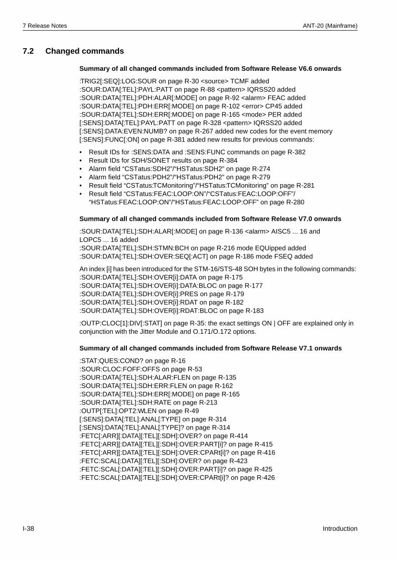
7 Release Notes ANT-20 (Mainframe)
7.2 Changed commands
Summary of all changed commands included from Software Release V6.6 onwards
:TRIG2[:SEQ]:LOG:SOUR on page R-30 <source> TCMF added:SOUR:DATA[:TEL]:PAYL:PATT on page R-88 <pattern> IQRSS20 added:SOUR:DATA[:TEL]:PDH:ALAR[:MODE] on page R-92 <alarm> FEAC added:SOUR:DATA[:TEL]:PDH:ERR[:MODE] on page R-102 <error> CP45 added:SOUR:DATA[:TEL]:SDH:ERR[:MODE] on page R-165 <mode> PER added[:SENS]:DATA[:TEL]:PAYL:PATT on page R-328 <pattern> IQRSS20 added[:SENS]:DATA:EVEN:NUMB? on page R-267 added new codes for the event memory[:SENS]:FUNC[:ON] on page R-381 added new results for previous commands:
• Result IDs for :SENS:DATA and :SENS:FUNC commands on page R-382• Result IDs for SDH/SONET results on page R-384• Alarm field “CSTatus:SDH2”/“HSTatus:SDH2” on page R-274• Alarm field “CSTatus:PDH2”/“HSTatus:PDH2” on page R-279• Result field “CSTatus:TCMonitoring”/“HSTatus:TCMonitoring” on page R-281• Result field “CSTatus:FEAC:LOOP:ON”/“CSTatus:FEAC:LOOP:OFF”/
“HSTatus:FEAC:LOOP:ON”/“HSTatus:FEAC:LOOP:OFF” on page R-280
Summary of all changed commands included from Software Release V7.0 onwards
:SOUR:DATA[:TEL]:SDH:ALAR[:MODE] on page R-136 <alarm> AISC5 ... 16 and LOPC5 ... 16 added:SOUR:DATA[:TEL]:SDH:STMN:BCH on page R-216 mode EQUipped added:SOUR:DATA[:TEL]:SDH:OVER:SEQ[:ACT] on page R-186 mode FSEQ added
An index [i] has been introduced for the STM-16/STS-48 SOH bytes in the following commands: :SOUR:DATA[:TEL]:SDH:OVER[i]:DATA on page R-175:SOUR:DATA[:TEL]:SDH:OVER[i]:DATA:BLOC on page R-177:SOUR:DATA[:TEL]:SDH:OVER[i]:PRES on page R-179:SOUR:DATA[:TEL]:SDH:OVER[i]:RDAT on page R-182:SOUR:DATA[:TEL]:SDH:OVER[i]:RDAT:BLOC on page R-183
:OUTP:CLOC[1]:DIV[:STAT] on page R-35: the exact settings ON | OFF are explained only in conjunction with the Jitter Module and O.171/O.172 options.
Summary of all changed commands included from Software Release V7.1 onwards
:STAT:QUES:COND? on page R-16:SOUR:CLOC:FOFF:OFFS on page R-53:SOUR:DATA[:TEL]:SDH:ALAR:FLEN on page R-135:SOUR:DATA[:TEL]:SDH:ERR:FLEN on page R-162:SOUR:DATA[:TEL]:SDH:ERR[:MODE] on page R-165:SOUR:DATA[:TEL]:SDH:RATE on page R-213:OUTP[:TEL]:OPT2:WLEN on page R-49[:SENS]:DATA[:TEL]:ANAL[:TYPE] on page R-314[:SENS]:DATA[:TEL]:ANAL[:TYPE]? on page R-314:FETC[:ARR][:DATA][:TEL][:SDH]:OVER? on page R-414:FETC[:ARR][:DATA][:TEL][:SDH]:OVER:PART[i]? on page R-415:FETC[:ARR][:DATA][:TEL][:SDH]:OVER:CPARt[i]? on page R-416:FETC:SCAL[:DATA][:TEL][:SDH]:OVER? on page R-423:FETC:SCAL[:DATA][:TEL][:SDH]:OVER:PART[i]? on page R-425:FETC:SCAL[:DATA][:TEL][:SDH]:OVER:CPARt[i]? on page R-426
I-38 Introduction
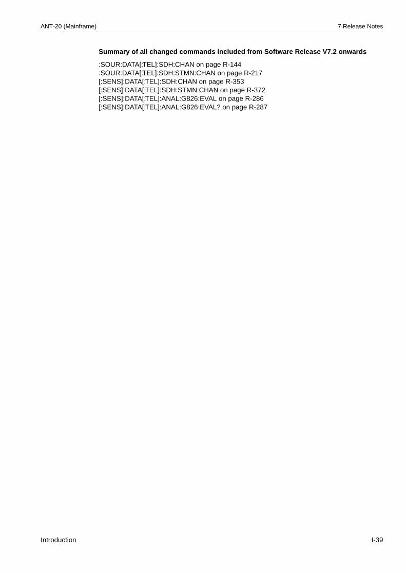
ANT-20 (Mainframe) 7 Release Notes
Summary of all changed commands included from Software Release V7.2 onwards
:SOUR:DATA[:TEL]:SDH:CHAN on page R-144:SOUR:DATA[:TEL]:SDH:STMN:CHAN on page R-217 [:SENS]:DATA[:TEL]:SDH:CHAN on page R-353[:SENS]:DATA[:TEL]:SDH:STMN:CHAN on page R-372[:SENS]:DATA[:TEL]:ANAL:G826:EVAL on page R-286[:SENS]:DATA[:TEL]:ANAL:G826:EVAL? on page R-287
Introduction I-39

7 Release Notes ANT-20 (Mainframe)
Notes:
I-40 Introduction
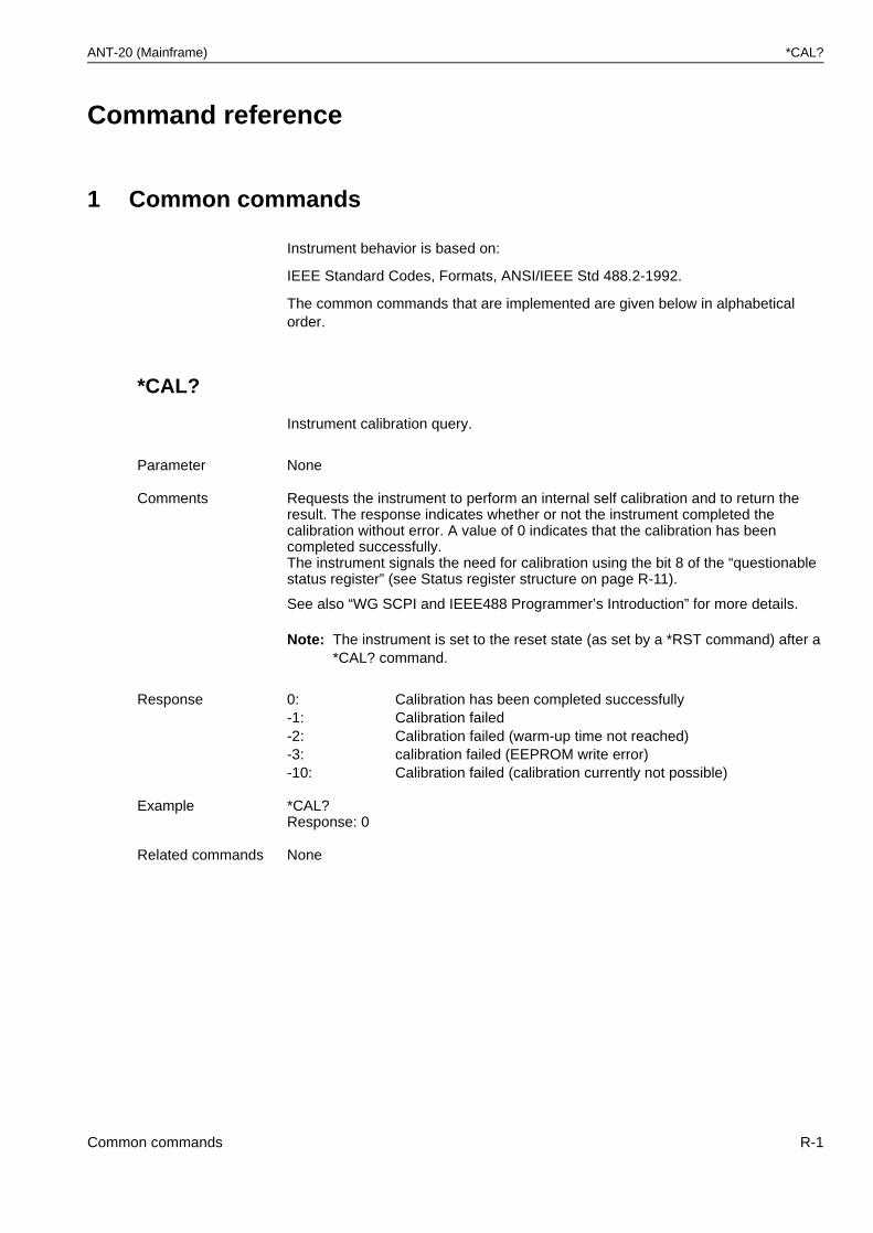
ANT-20 (Mainframe) *CAL?
Command reference
1 Common commands
Instrument behavior is based on:
IEEE Standard Codes, Formats, ANSI/IEEE Std 488.2-1992.
The common commands that are implemented are given below in alphabetical order.
*CAL?
Instrument calibration query.
Note: The instrument is set to the reset state (as set by a *RST command) after a *CAL? command.
Parameter None
Comments Requests the instrument to perform an internal self calibration and to return the result. The response indicates whether or not the instrument completed the calibration without error. A value of 0 indicates that the calibration has been completed successfully.The instrument signals the need for calibration using the bit 8 of the “questionable status register” (see Status register structure on page R-11).
See also “WG SCPI and IEEE488 Programmer’s Introduction” for more details.
Response 0: Calibration has been completed successfully-1: Calibration failed-2: Calibration failed (warm-up time not reached)-3: calibration failed (EEPROM write error)-10: Calibration failed (calibration currently not possible)
Example *CAL?Response: 0
Related commands None
Common commands R-1
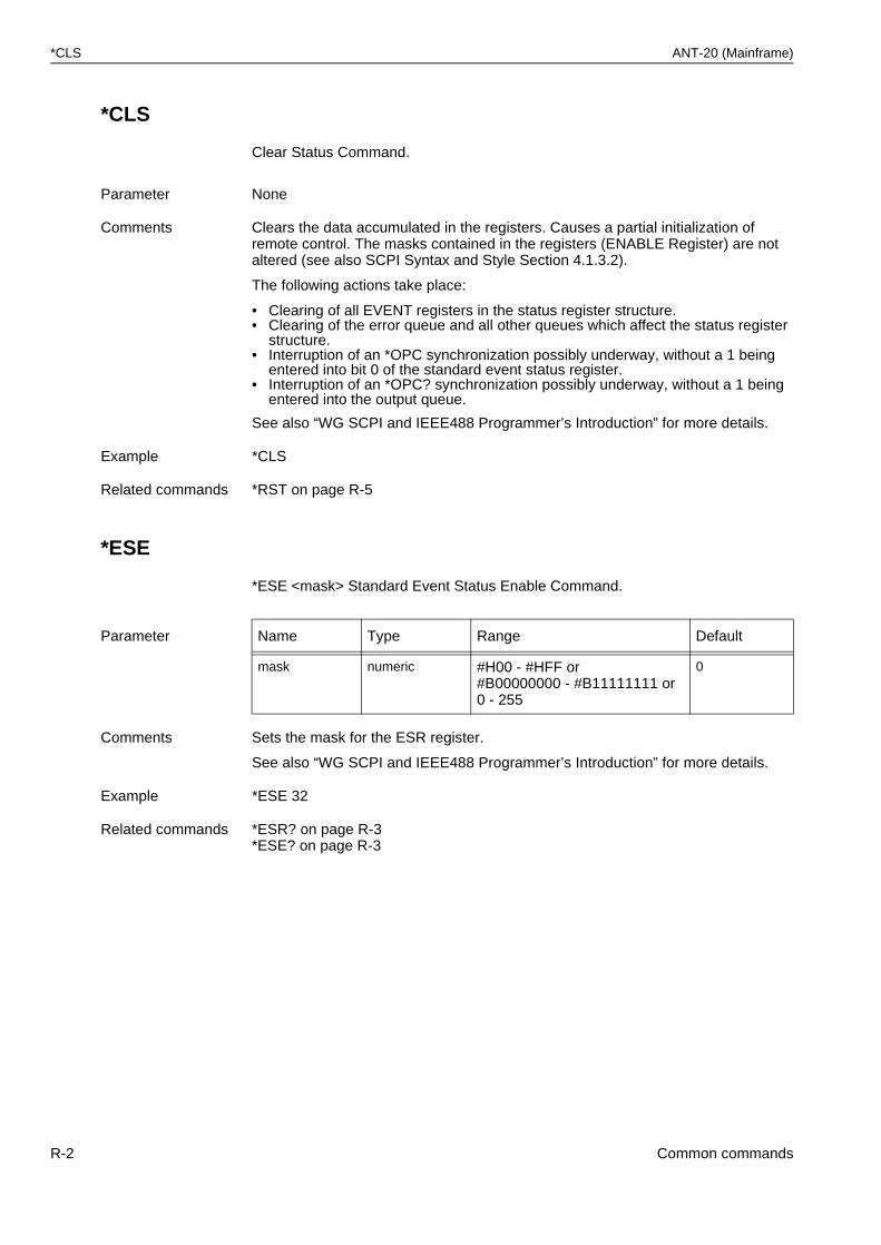
*CLS ANT-20 (Mainframe)
*CLS
Clear Status Command.
*ESE
*ESE <mask> Standard Event Status Enable Command.
Parameter None
Comments Clears the data accumulated in the registers. Causes a partial initialization of remote control. The masks contained in the registers (ENABLE Register) are not altered (see also SCPI Syntax and Style Section 4.1.3.2).
The following actions take place:
• Clearing of all EVENT registers in the status register structure.• Clearing of the error queue and all other queues which affect the status register
structure.• Interruption of an *OPC synchronization possibly underway, without a 1 being
entered into bit 0 of the standard event status register.• Interruption of an *OPC? synchronization possibly underway, without a 1 being
entered into the output queue.
See also “WG SCPI and IEEE488 Programmer’s Introduction” for more details.
Example *CLS
Related commands *RST on page R-5
Parameter Name Type Range Default
mask numeric #H00 - #HFF or#B00000000 - #B11111111 or0 - 255
0
Comments Sets the mask for the ESR register.
See also “WG SCPI and IEEE488 Programmer’s Introduction” for more details.
Example *ESE 32
Related commands *ESR? on page R-3*ESE? on page R-3
R-2 Common commands
ANT-20 (Mainframe) *ESE?
*ESE?
Standard Event Status Enable Query.
*ESR?
Standard Event Status Register Query.
Parameter None
Comments Reads the mask for the ESR register.
See also “WG SCPI and IEEE488 Programmer’s Introduction” for more details.
Example *ESE?Response: 64
Related commands *ESR? on page R-3*ESE on page R-2
Parameter None
Comments Reads out the status register ESR. Range from 0 - 255.
See also “WG SCPI and IEEE488 Programmer’s Introduction” for more details.
Example *ESR?Response: 64
Related commands *ESE on page R-2
Common commands R-3
*IDN? ANT-20 (Mainframe)
*IDN?
Identification Query.
Note: This command must always be the last query in a programming command (see also IEEE 488.2 Section 10.14.2.2). The response is always terminated with a <NL> (0A HEX).
*OPC
Operation Complete Command.
Note: Execution of this command is started after all previously received commands (sequential command).
Parameter None
Comments Reads out the instrument identification consisting of 4 fields, separated by “,”: <Manufacturer>,<Instrument name>,<Serial no.>,<Firmware level><Manufacturer>:WANDEL&GOLTERMANN<Instrument name>:ANT-20 / <Keycode no.><Serial no.>: A-0050<Firmware level>:<Software version>/<Product no.>/<Version>/<VXI code(HEX)>/<Card ID(HEX)>
Example *IDN?Response: WANDEL&GOLTERMANN,ANT-20/0A1234500000,B-0078,6.00/3035/01/0C01/0255<NL>
Related commands None
Parameter None
Comments Sets the OPC bit in the standard event status register ESR as soon as the instrument has assumed the idle state. Used to synchronize overlapping commands.Use of this command makes sense only in conjunction with a service request (SRQ).
See also “WG SCPI and IEEE488 Programmer’s Introduction” for more details.
Example *OPC
Related commands *OPC? on page R-5*WAI on page R-7
R-4 Common commands
ANT-20 (Mainframe) *OPC?
*OPC?
Operation Complete Query.
*OPT?
Option Identification Query.
Note: This command must always be the last query in a programming command (see also IEEE 488.2 Section 10.20.2.2). The response is always terminated with a <NL> (0A HEX).
*RST
Reset Command.
Note: Execution of this command is started after all previously received commands (sequential command).
Parameter None
Comments Outputs an ASCII “1” to the output buffer of the instrument as soon as it is in the idle state.As soon as all settings in the instrument are complete, a “1” is written to the output buffer. Used to synchronize the user and instrument for overlapping commands.
Example *OPC?
Related commands *OPC on page R-4*WAI on page R-7
Parameter None
Comments Outputs a list of the options available in the instrument.
Example *OPT?Response: 3035/90.33,3035/90.48 with various options set.
Related commands None
Parameter None
Comments Instrument initialization.The instrument goes to the STOP state and sets itself to defined default settings. The result memory, event FIFO and list of desired results formed with :SENS:FUNC are cleared! “*RST” does not include the initialization operations which are executed with “*CLS”!
See also “WG SCPI and IEEE488 Programmer’s Introduction” for more details.
Example *RST
Related commands *CLS on page R-2
Common commands R-5
*SRE ANT-20 (Mainframe)
*SRE
*SRE <mask> Service Request Enable Command.
Note: Bit number 6 (MSS) cannot be set and is ignored.
*SRE?
Service Request Enable Query.
Note: Bit number 6 (MSS) cannot be set and is always read as 0.
Parameter Name Type Range Default
mask numeric #H00 - #HFF or#B00000000 - #B11111111 or0 - 255
0
Comments Sets the mask for service request (SRQ).
See also “WG SCPI and IEEE488 Programmer’s Introduction” for more details
Example *SRE 128
Related commands *SRE? on page R-6*STB? on page R-7
Parameter None
Comments Reads out the bit mask (0 - 191) for forming the service request (SRQ).
See also “WG SCPI and IEEE488 Programmer’s Introduction” for more details.
Example *SRE?Response: 128
Related commands *SRE on page R-6*STB? on page R-7
R-6 Common commands
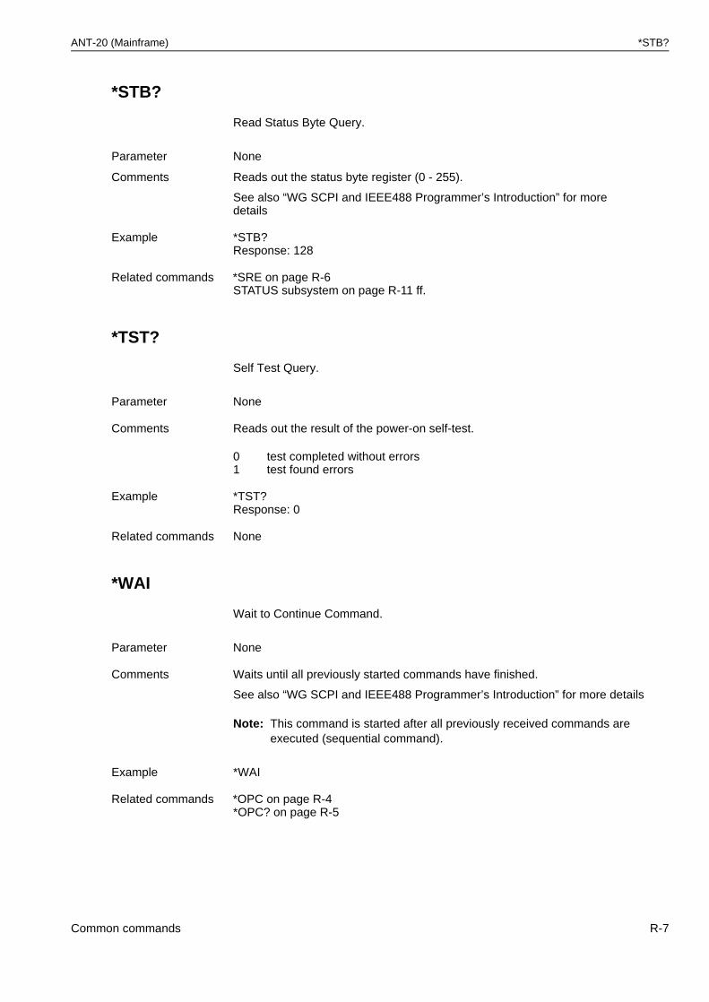
ANT-20 (Mainframe) *STB?
*STB?
Read Status Byte Query.
*TST?
Self Test Query.
*WAI
Wait to Continue Command.
Note: This command is started after all previously received commands are executed (sequential command).
Parameter None
Comments Reads out the status byte register (0 - 255).
See also “WG SCPI and IEEE488 Programmer’s Introduction” for more details
Example *STB?Response: 128
Related commands *SRE on page R-6STATUS subsystem on page R-11 ff.
Parameter None
Comments Reads out the result of the power-on self-test.
01
test completed without errorstest found errors
Example *TST?Response: 0
Related commands None
Parameter None
Comments Waits until all previously started commands have finished.
See also “WG SCPI and IEEE488 Programmer’s Introduction” for more details
Example *WAI
Related commands *OPC on page R-4*OPC? on page R-5
Common commands R-7

*WAI ANT-20 (Mainframe)
Notes:
R-8 Common commands
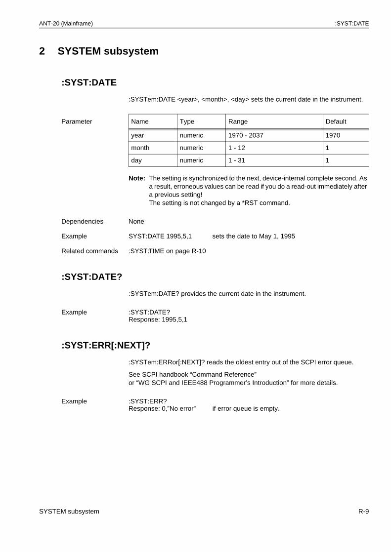
ANT-20 (Mainframe) :SYST:DATE
2 SYSTEM subsystem
:SYST:DATE
:SYSTem:DATE <year>, <month>, <day> sets the current date in the instrument.
Note: The setting is synchronized to the next, device-internal complete second. As a result, erroneous values can be read if you do a read-out immediately after a previous setting!The setting is not changed by a *RST command.
:SYST:DATE?
:SYSTem:DATE? provides the current date in the instrument.
:SYST:ERR[:NEXT]?
:SYSTem:ERRor[:NEXT]? reads the oldest entry out of the SCPI error queue.
See SCPI handbook “Command Reference”or “WG SCPI and IEEE488 Programmer’s Introduction” for more details.
Parameter Name Type Range Default
year numeric 1970 - 2037 1970
month numeric 1 - 12 1
day numeric 1 - 31 1
Dependencies None
Example SYST:DATE 1995,5,1 sets the date to May 1, 1995
Related commands :SYST:TIME on page R-10
Example :SYST:DATE?Response: 1995,5,1
Example :SYST:ERR?Response: 0,”No error” if error queue is empty.
SYSTEM subsystem R-9
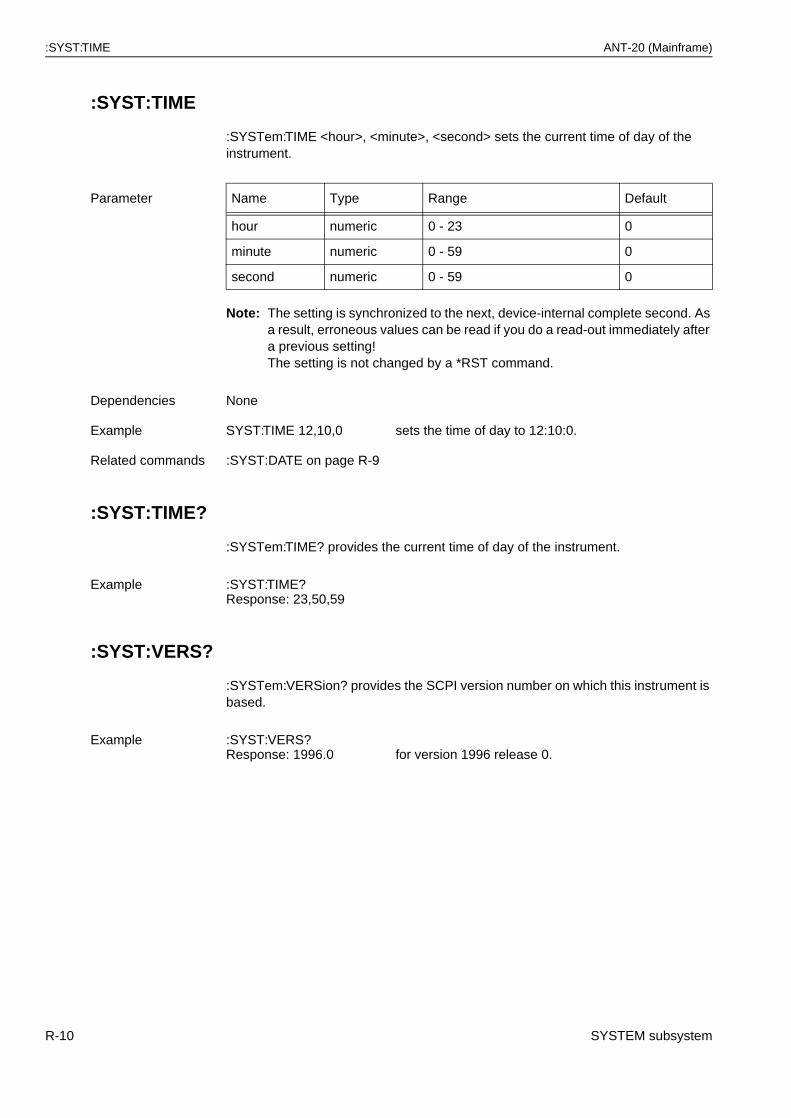
:SYST:TIME ANT-20 (Mainframe)
:SYST:TIME
:SYSTem:TIME <hour>, <minute>, <second> sets the current time of day of the instrument.
Note: The setting is synchronized to the next, device-internal complete second. As a result, erroneous values can be read if you do a read-out immediately after a previous setting!The setting is not changed by a *RST command.
:SYST:TIME?
:SYSTem:TIME? provides the current time of day of the instrument.
:SYST:VERS?
:SYSTem:VERSion? provides the SCPI version number on which this instrument is based.
Parameter Name Type Range Default
hour numeric 0 - 23 0
minute numeric 0 - 59 0
second numeric 0 - 59 0
Dependencies None
Example SYST:TIME 12,10,0 sets the time of day to 12:10:0.
Related commands :SYST:DATE on page R-9
Example :SYST:TIME?Response: 23,50,59
Example :SYST:VERS?Response: 1996.0 for version 1996 release 0.
R-10 SYSTEM subsystem
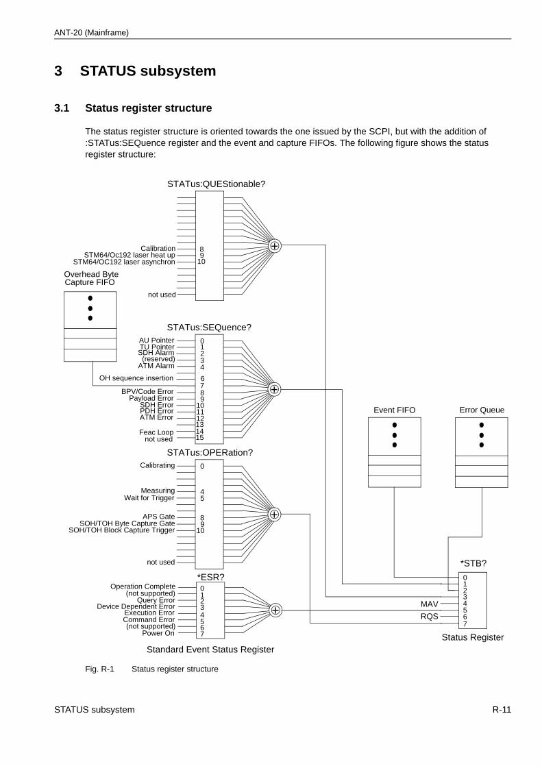
ANT-20 (Mainframe)
3 STATUS subsystem
3.1 Status register structure
The status register structure is oriented towards the one issued by the SCPI, but with the addition of:STATus:SEQuence register and the event and capture FIFOs. The following figure shows the status register structure:
Fig. R-1 Status register structure
STATus:QUEStionable?
STATus:OPERation?
4
0
Measuring
not used
not used
Standard Event Status Register
01234567
Operation Complete(not supported)
Query ErrorDevice Dependent Error
Execution ErrorCommand Error(not supported)
Power On
*ESR?
*STB?
01234567
MAV
RQS
Error Queue
Status Register
5Wait for Trigger
STATus:SEQuence?
21
11
89
10
AU Pointer
SDH Alarm
not used
3
BPV/Code Error
0TU Pointer
(reserved)
SDH ErrorPDH Error
Payload Error
4ATM Alarm
12ATM ErrorEvent FIFO
8Calibration
Calibrating
8APS Gate
Capture FIFO
7
9SOH/TOH Byte Capture Gate
Overhead Byte
OH sequence insertion 6
131415
Feac Loop
10SOH/TOH Block Capture Trigger
9STM64/Oc192 laser heat up10STM64/OC192 laser asynchron
STATUS subsystem R-11
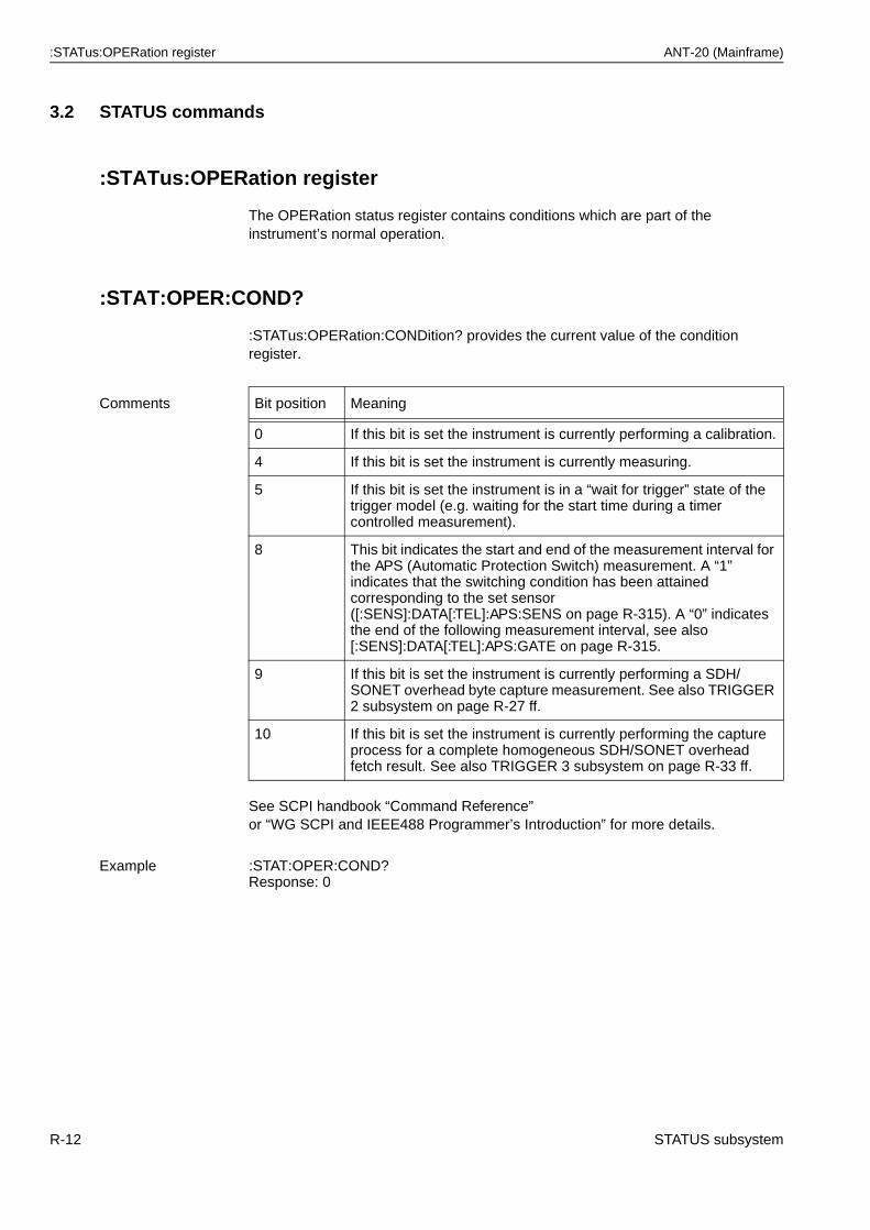
:STATus:OPERation register ANT-20 (Mainframe)
3.2 STATUS commands
:STATus:OPERation register
The OPERation status register contains conditions which are part of the instrument’s normal operation.
:STAT:OPER:COND?
:STATus:OPERation:CONDition? provides the current value of the condition register.
See SCPI handbook “Command Reference”or “WG SCPI and IEEE488 Programmer’s Introduction” for more details.
Comments Bit position Meaning
0 If this bit is set the instrument is currently performing a calibration.
4 If this bit is set the instrument is currently measuring.
5 If this bit is set the instrument is in a “wait for trigger” state of the trigger model (e.g. waiting for the start time during a timer controlled measurement).
8 This bit indicates the start and end of the measurement interval for the APS (Automatic Protection Switch) measurement. A “1” indicates that the switching condition has been attained corresponding to the set sensor ([:SENS]:DATA[:TEL]:APS:SENS on page R-315). A “0” indicates the end of the following measurement interval, see also [:SENS]:DATA[:TEL]:APS:GATE on page R-315.
9 If this bit is set the instrument is currently performing a SDH/SONET overhead byte capture measurement. See also TRIGGER 2 subsystem on page R-27 ff.
10 If this bit is set the instrument is currently performing the capture process for a complete homogeneous SDH/SONET overhead fetch result. See also TRIGGER 3 subsystem on page R-33 ff.
Example :STAT:OPER:COND?Response: 0
R-12 STATUS subsystem
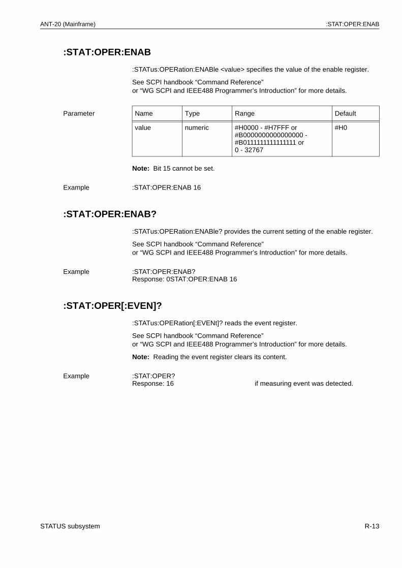
ANT-20 (Mainframe) :STAT:OPER:ENAB
:STAT:OPER:ENAB
:STATus:OPERation:ENABle <value> specifies the value of the enable register.
See SCPI handbook “Command Reference”or “WG SCPI and IEEE488 Programmer’s Introduction” for more details.
Note: Bit 15 cannot be set.
:STAT:OPER:ENAB?
:STATus:OPERation:ENABle? provides the current setting of the enable register.
See SCPI handbook “Command Reference”or “WG SCPI and IEEE488 Programmer’s Introduction” for more details.
:STAT:OPER[:EVEN]?
:STATus:OPERation[:EVENt]? reads the event register.
See SCPI handbook “Command Reference”or “WG SCPI and IEEE488 Programmer’s Introduction” for more details.
Note: Reading the event register clears its content.
Parameter Name Type Range Default
value numeric #H0000 - #H7FFF or#B0000000000000000 -#B0111111111111111 or0 - 32767
#H0
Example :STAT:OPER:ENAB 16
Example :STAT:OPER:ENAB?Response: 0STAT:OPER:ENAB 16
Example :STAT:OPER?Response: 16 if measuring event was detected.
STATUS subsystem R-13
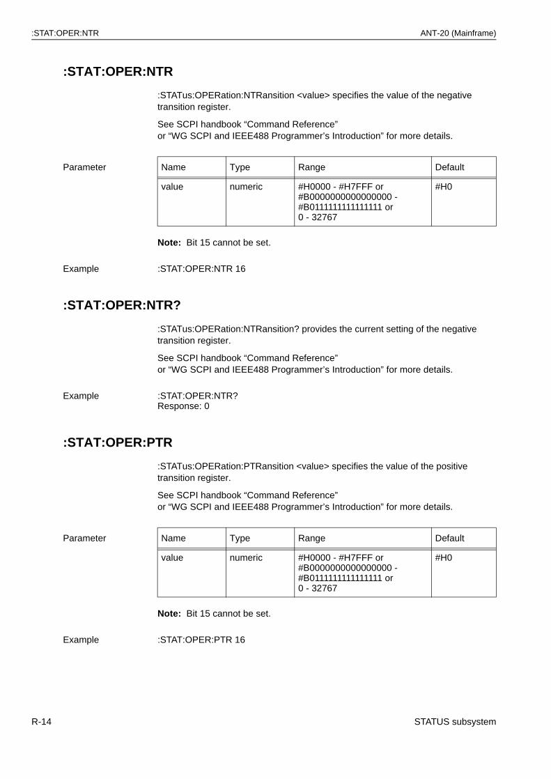
:STAT:OPER:NTR ANT-20 (Mainframe)
:STAT:OPER:NTR
:STATus:OPERation:NTRansition <value> specifies the value of the negative transition register.
See SCPI handbook “Command Reference”or “WG SCPI and IEEE488 Programmer’s Introduction” for more details.
Note: Bit 15 cannot be set.
:STAT:OPER:NTR?
:STATus:OPERation:NTRansition? provides the current setting of the negative transition register.
See SCPI handbook “Command Reference”or “WG SCPI and IEEE488 Programmer’s Introduction” for more details.
:STAT:OPER:PTR
:STATus:OPERation:PTRansition <value> specifies the value of the positive transition register.
See SCPI handbook “Command Reference”or “WG SCPI and IEEE488 Programmer’s Introduction” for more details.
Note: Bit 15 cannot be set.
Parameter Name Type Range Default
value numeric #H0000 - #H7FFF or#B0000000000000000 -#B0111111111111111 or0 - 32767
#H0
Example :STAT:OPER:NTR 16
Example :STAT:OPER:NTR?Response: 0
Parameter Name Type Range Default
value numeric #H0000 - #H7FFF or#B0000000000000000 -#B0111111111111111 or0 - 32767
#H0
Example :STAT:OPER:PTR 16
R-14 STATUS subsystem
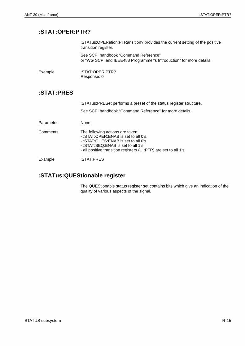
ANT-20 (Mainframe) :STAT:OPER:PTR?
:STAT:OPER:PTR?
:STATus:OPERation:PTRansition? provides the current setting of the positive transition register.
See SCPI handbook “Command Reference”or “WG SCPI and IEEE488 Programmer’s Introduction” for more details.
:STAT:PRES
:STATus:PRESet performs a preset of the status register structure.
See SCPI handbook “Command Reference” for more details.
:STATus:QUEStionable register
The QUEStionable status register set contains bits which give an indication of the quality of various aspects of the signal.
Example :STAT:OPER:PTR?Response: 0
Parameter None
Comments The following actions are taken:- :STAT:OPER:ENAB is set to all 0’s.- :STAT:QUES:ENAB is set to all 0’s.- :STAT:SEQ:ENAB is set to all 1’s.- all positive transition registers (…:PTR) are set to all 1’s.
Example :STAT:PRES
STATUS subsystem R-15
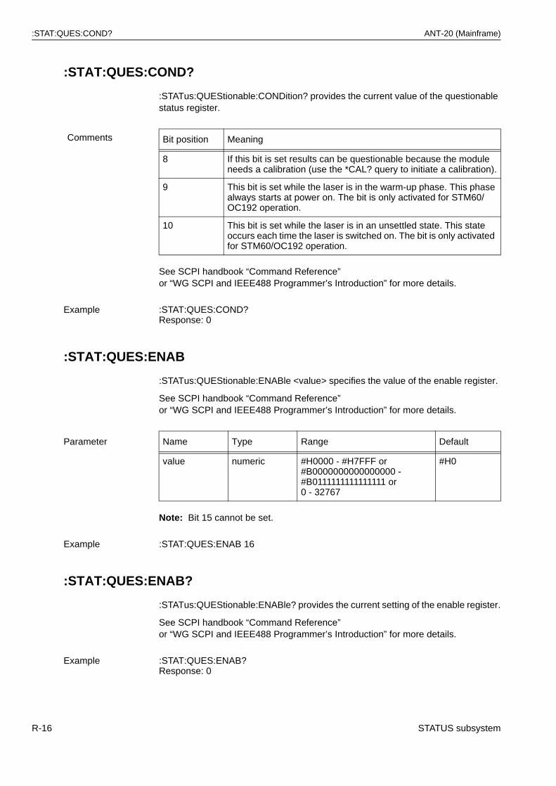
:STAT:QUES:COND? ANT-20 (Mainframe)
:STAT:QUES:COND?
:STATus:QUEStionable:CONDition? provides the current value of the questionable status register.
See SCPI handbook “Command Reference”or “WG SCPI and IEEE488 Programmer’s Introduction” for more details.
:STAT:QUES:ENAB
:STATus:QUEStionable:ENABle <value> specifies the value of the enable register.
See SCPI handbook “Command Reference”or “WG SCPI and IEEE488 Programmer’s Introduction” for more details.
Note: Bit 15 cannot be set.
:STAT:QUES:ENAB?
:STATus:QUEStionable:ENABle? provides the current setting of the enable register.
See SCPI handbook “Command Reference”or “WG SCPI and IEEE488 Programmer’s Introduction” for more details.
Comments Bit position Meaning
8 If this bit is set results can be questionable because the module needs a calibration (use the *CAL? query to initiate a calibration).
9 This bit is set while the laser is in the warm-up phase. This phase always starts at power on. The bit is only activated for STM60/OC192 operation.
10 This bit is set while the laser is in an unsettled state. This state occurs each time the laser is switched on. The bit is only activated for STM60/OC192 operation.
Example :STAT:QUES:COND?Response: 0
Parameter Name Type Range Default
value numeric #H0000 - #H7FFF or#B0000000000000000 -#B0111111111111111 or0 - 32767
#H0
Example :STAT:QUES:ENAB 16
Example :STAT:QUES:ENAB?Response: 0
R-16 STATUS subsystem
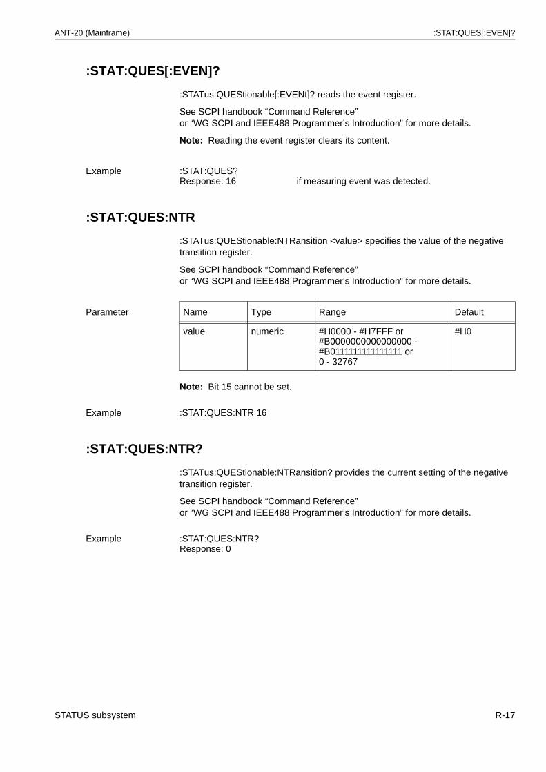
ANT-20 (Mainframe) :STAT:QUES[:EVEN]?
:STAT:QUES[:EVEN]?
:STATus:QUEStionable[:EVENt]? reads the event register.
See SCPI handbook “Command Reference”or “WG SCPI and IEEE488 Programmer’s Introduction” for more details.
Note: Reading the event register clears its content.
:STAT:QUES:NTR
:STATus:QUEStionable:NTRansition <value> specifies the value of the negative transition register.
See SCPI handbook “Command Reference”or “WG SCPI and IEEE488 Programmer’s Introduction” for more details.
Note: Bit 15 cannot be set.
:STAT:QUES:NTR?
:STATus:QUEStionable:NTRansition? provides the current setting of the negative transition register.
See SCPI handbook “Command Reference”or “WG SCPI and IEEE488 Programmer’s Introduction” for more details.
Example :STAT:QUES?Response: 16 if measuring event was detected.
Parameter Name Type Range Default
value numeric #H0000 - #H7FFF or#B0000000000000000 -#B0111111111111111 or0 - 32767
#H0
Example :STAT:QUES:NTR 16
Example :STAT:QUES:NTR?Response: 0
STATUS subsystem R-17
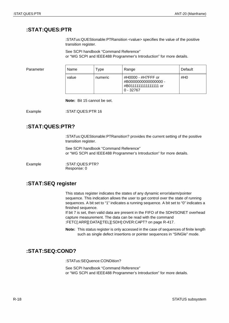
:STAT:QUES:PTR ANT-20 (Mainframe)
:STAT:QUES:PTR
:STATus:QUEStionable:PTRansition <value> specifies the value of the positive transition register.
See SCPI handbook “Command Reference”or “WG SCPI and IEEE488 Programmer’s Introduction” for more details.
Note: Bit 15 cannot be set.
:STAT:QUES:PTR?
:STATus:QUEStionable:PTRansition? provides the current setting of the positive transition register.
See SCPI handbook “Command Reference”or “WG SCPI and IEEE488 Programmer’s Introduction” for more details.
:STAT:SEQ register
This status register indicates the states of any dynamic error/alarm/pointer sequence. This indication allows the user to get control over the state of running sequences. A bit set to “1” indicates a running sequence. A bit set to “0” indicates a finished sequence.If bit 7 is set, then valid data are present in the FIFO of the SDH/SONET overhead capture measurement. The data can be read with the command :FETC[:ARR][:DATA][:TEL][:SDH]:OVER:CAPT? on page R-417.
Note: This status register is only accessed in the case of sequences of finite length such as single defect insertions or pointer sequences in “SINGle” mode.
:STAT:SEQ:COND?
:STATus:SEQuence:CONDition?
See SCPI handbook “Command Reference”or “WG SCPI and IEEE488 Programmer’s Introduction” for more details.
Parameter Name Type Range Default
value numeric #H0000 - #H7FFF or#B0000000000000000 -#B0111111111111111 or0 - 32767
#H0
Example :STAT:QUES:PTR 16
Example :STAT:QUES:PTR?Response: 0
R-18 STATUS subsystem
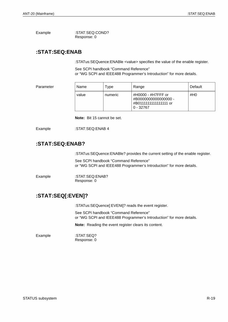
ANT-20 (Mainframe) :STAT:SEQ:ENAB
:STAT:SEQ:ENAB
:STATus:SEQuence:ENABle <value> specifies the value of the enable register.
See SCPI handbook “Command Reference”or “WG SCPI and IEEE488 Programmer’s Introduction” for more details.
Note: Bit 15 cannot be set.
:STAT:SEQ:ENAB?
:STATus:SEQuence:ENABle? provides the current setting of the enable register.
See SCPI handbook “Command Reference”or “WG SCPI and IEEE488 Programmer’s Introduction” for more details.
:STAT:SEQ[:EVEN]?
:STATus:SEQuence[:EVENt]? reads the event register.
See SCPI handbook “Command Reference”or “WG SCPI and IEEE488 Programmer’s Introduction” for more details.
Note: Reading the event register clears its content.
Example :STAT:SEQ:COND?Response: 0
Parameter Name Type Range Default
value numeric #H0000 - #H7FFF or#B0000000000000000 -#B0111111111111111 or0 - 32767
#H0
Example :STAT:SEQ:ENAB 4
Example :STAT:SEQ:ENAB?Response: 0
Example :STAT:SEQ?Response: 0
STATUS subsystem R-19
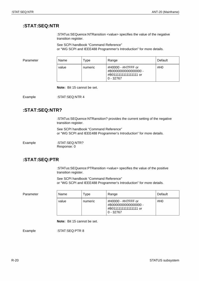
:STAT:SEQ:NTR ANT-20 (Mainframe)
:STAT:SEQ:NTR
:STATus:SEQuence:NTRansition <value> specifies the value of the negative transition register.
See SCPI handbook “Command Reference”or “WG SCPI and IEEE488 Programmer’s Introduction” for more details.
Note: Bit 15 cannot be set.
:STAT:SEQ:NTR?
:STATus:SEQuence:NTRansition? provides the current setting of the negative transition register.
See SCPI handbook “Command Reference”or “WG SCPI and IEEE488 Programmer’s Introduction” for more details.
:STAT:SEQ:PTR
:STATus:SEQuence:PTRansition <value> specifies the value of the positive transition register.
See SCPI handbook “Command Reference”or “WG SCPI and IEEE488 Programmer’s Introduction” for more details.
Note: Bit 15 cannot be set.
Parameter Name Type Range Default
value numeric #H0000 - #H7FFF or#B0000000000000000 -#B0111111111111111 or0 - 32767
#H0
Example :STAT:SEQ:NTR 4
Example :STAT:SEQ:NTR?Response: 0
Parameter Name Type Range Default
value numeric #H0000 - #H7FFF or#B0000000000000000 -#B0111111111111111 or0 - 32767
#H0
Example :STAT:SEQ:PTR 8
R-20 STATUS subsystem

ANT-20 (Mainframe) :STAT:SEQ:PTR?
:STAT:SEQ:PTR?
:STATus:SEQuence:PTRansition? provides the current setting of the positive transition register.
See SCPI handbook “Command Reference”or “WG SCPI and IEEE488 Programmer’s Introduction” for more details.
Example :STAT:SEQ:PTR?Response: 0
STATUS subsystem R-21

:STAT:SEQ:PTR? ANT-20 (Mainframe)
Notes:
R-22 STATUS subsystem
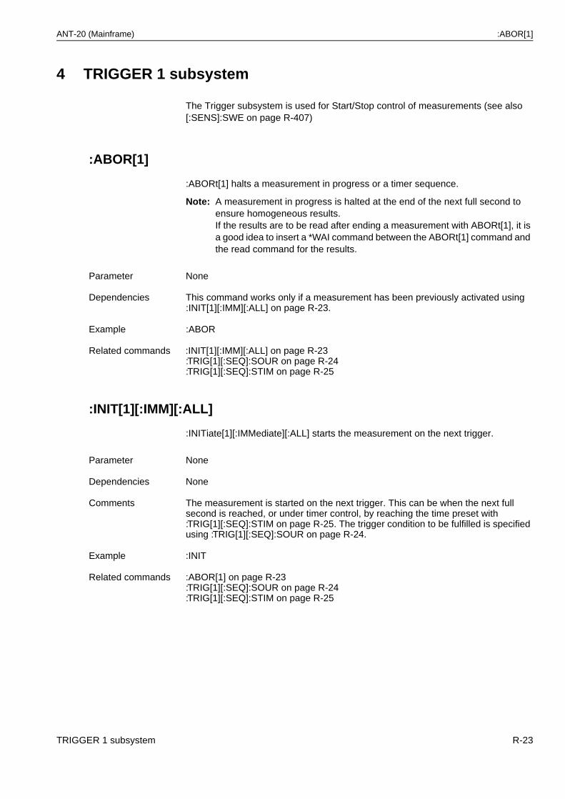
ANT-20 (Mainframe) :ABOR[1]
4 TRIGGER 1 subsystem
The Trigger subsystem is used for Start/Stop control of measurements (see also [:SENS]:SWE on page R-407)
:ABOR[1]
:ABORt[1] halts a measurement in progress or a timer sequence.
Note: A measurement in progress is halted at the end of the next full second to ensure homogeneous results.If the results are to be read after ending a measurement with ABORt[1], it is a good idea to insert a *WAI command between the ABORt[1] command and the read command for the results.
:INIT[1][:IMM][:ALL]
:INITiate[1][:IMMediate][:ALL] starts the measurement on the next trigger.
Parameter None
Dependencies This command works only if a measurement has been previously activated using :INIT[1][:IMM][:ALL] on page R-23.
Example :ABOR
Related commands :INIT[1][:IMM][:ALL] on page R-23:TRIG[1][:SEQ]:SOUR on page R-24:TRIG[1][:SEQ]:STIM on page R-25
Parameter None
Dependencies None
Comments The measurement is started on the next trigger. This can be when the next full second is reached, or under timer control, by reaching the time preset with :TRIG[1][:SEQ]:STIM on page R-25. The trigger condition to be fulfilled is specified using :TRIG[1][:SEQ]:SOUR on page R-24.
Example :INIT
Related commands :ABOR[1] on page R-23:TRIG[1][:SEQ]:SOUR on page R-24:TRIG[1][:SEQ]:STIM on page R-25
TRIGGER 1 subsystem R-23
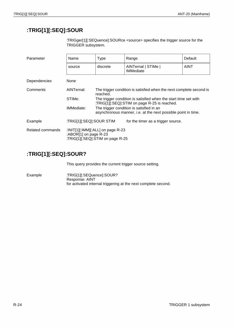
:TRIG[1][:SEQ]:SOUR ANT-20 (Mainframe)
:TRIG[1][:SEQ]:SOUR
:TRIGger[1][:SEQuence]:SOURce <source> specifies the trigger source for the TRIGGER subsystem.
:TRIG[1][:SEQ]:SOUR?
This query provides the current trigger source setting.
Parameter Name Type Range Default
source discrete AINTernal | STIMe |IMMediate
AINT
Dependencies None
Comments AINTernal: The trigger condition is satisfied when the next complete second is reached.
STIMe: The trigger condition is satisfied when the start time set with :TRIG[1][:SEQ]:STIM on page R-25 is reached.
IMMediate: The trigger condition is satisfied in an asynchronous manner, i.e. at the next possible point in time.
Example :TRIG[1][:SEQ]:SOUR STIM for the timer as a trigger source.
Related commands :INIT[1][:IMM][:ALL] on page R-23:ABOR[1] on page R-23:TRIG[1][:SEQ]:STIM on page R-25
Example :TRIG[1][:SEQuence]:SOUR?Response: AINTfor activated internal triggering at the next complete second.
R-24 TRIGGER 1 subsystem
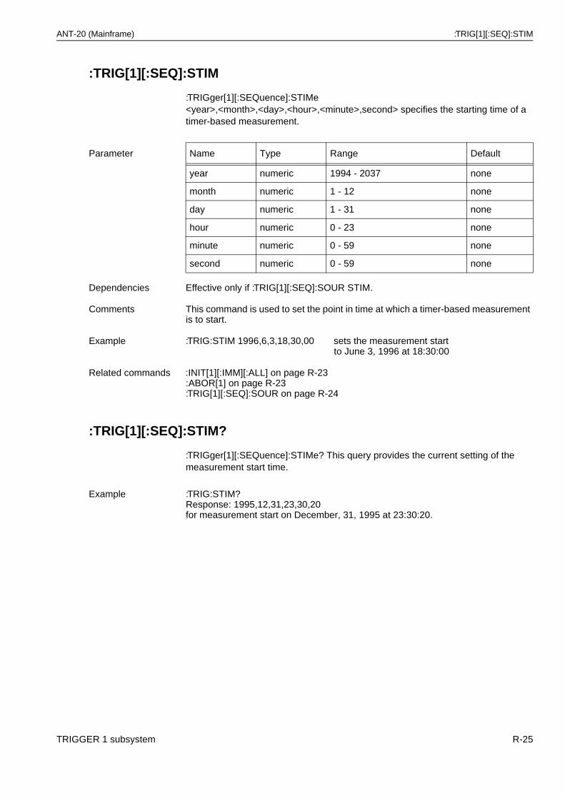
ANT-20 (Mainframe) :TRIG[1][:SEQ]:STIM
:TRIG[1][:SEQ]:STIM
:TRIGger[1][:SEQuence]:STIMe <year>,<month>,<day>,<hour>,<minute>,second> specifies the starting time of a timer-based measurement.
:TRIG[1][:SEQ]:STIM?
:TRIGger[1][:SEQuence]:STIMe? This query provides the current setting of the measurement start time.
Parameter Name Type Range Default
year numeric 1994 - 2037 none
month numeric 1 - 12 none
day numeric 1 - 31 none
hour numeric 0 - 23 none
minute numeric 0 - 59 none
second numeric 0 - 59 none
Dependencies Effective only if :TRIG[1][:SEQ]:SOUR STIM.
Comments This command is used to set the point in time at which a timer-based measurement is to start.
Example :TRIG:STIM 1996,6,3,18,30,00 sets the measurement startto June 3, 1996 at 18:30:00
Related commands :INIT[1][:IMM][:ALL] on page R-23:ABOR[1] on page R-23:TRIG[1][:SEQ]:SOUR on page R-24
Example :TRIG:STIM?Response: 1995,12,31,23,30,20for measurement start on December, 31, 1995 at 23:30:20.
TRIGGER 1 subsystem R-25

:TRIG[1][:SEQ]:STIM? ANT-20 (Mainframe)
Notes:
R-26 TRIGGER 1 subsystem
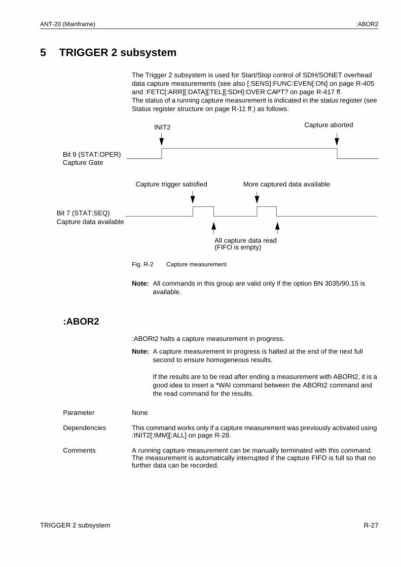
ANT-20 (Mainframe) :ABOR2
5 TRIGGER 2 subsystem
The Trigger 2 subsystem is used for Start/Stop control of SDH/SONET overhead data capture measurements (see also [:SENS]:FUNC:EVEN[:ON] on page R-405 and :FETC[:ARR][:DATA][:TEL][:SDH]:OVER:CAPT? on page R-417 ff.The status of a running capture measurement is indicated in the status register (see Status register structure on page R-11 ff.) as follows:
Fig. R-2 Capture measurement
Note: All commands in this group are valid only if the option BN 3035/90.15 is available.
:ABOR2
:ABORt2 halts a capture measurement in progress.
Note: A capture measurement in progress is halted at the end of the next full second to ensure homogeneous results.
If the results are to be read after ending a measurement with ABORt2, it is a good idea to insert a *WAI command between the ABORt2 command and the read command for the results.
Parameter None
Dependencies This command works only if a capture measurement was previously activated using :INIT2[:IMM][:ALL] on page R-28.
Comments A running capture measurement can be manually terminated with this command. The measurement is automatically interrupted if the capture FIFO is full so that no further data can be recorded.
Bit 9 (STAT:OPER)
INIT2 Capture aborted
Capture Gate
Bit 7 (STAT:SEQ)Capture data available
Capture trigger satisfied
All capture data read(FIFO is empty)
More captured data available
TRIGGER 2 subsystem R-27
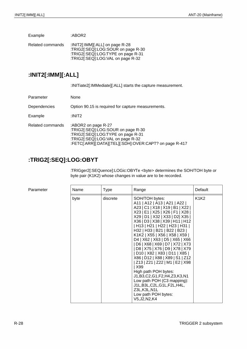
:INIT2[:IMM][:ALL] ANT-20 (Mainframe)
:INIT2[:IMM][:ALL]
:INITiate2[:IMMediate][:ALL] starts the capture measurement.
:TRIG2[:SEQ]:LOG:OBYT
:TRIGger2[:SEQuence]:LOGic:OBYTe <byte> determines the SOH/TOH byte or byte pair (K1K2) whose changes in value are to be recorded.
Example :ABOR2
Related commands :INIT2[:IMM][:ALL] on page R-28:TRIG2[:SEQ]:LOG:SOUR on page R-30:TRIG2[:SEQ]:LOG:TYPE on page R-31:TRIG2[:SEQ]:LOG:VAL on page R-32
Parameter None
Dependencies Option 90.15 is required for capture measurements.
Example :INIT2
Related commands :ABOR2 on page R-27:TRIG2[:SEQ]:LOG:SOUR on page R-30:TRIG2[:SEQ]:LOG:TYPE on page R-31:TRIG2[:SEQ]:LOG:VAL on page R-32:FETC[:ARR][:DATA][:TEL][:SDH]:OVER:CAPT? on page R-417
Parameter Name Type Range Default
byte discrete SOH/TOH bytes:A11 | A12 | A13 | A21 | A22 | A23 | C1 | X18 | X19 | B1 | X22 | X23 | E1 | X25 | X26 | F1 | X28 | X29 | D1 | X32 | X33 | D2| X35 | X36 | D3 | X38 | X39 | H11 | H12 | H13 | H21 | H22 | H23 | H31 | H32 | H33 | B21 | B22 | B23 | K1K2 | X55 | X56 | X58 | X59 | D4 | X62 | X63 | D5 | X65 | X66 | D6 | X68 | X69 | D7 | X72 | X73 | D8 | X75 | X76 | D9 | X78 | X79 | D10 | X82 | X83 | D11 | X85 | X86 | D12 | X88 | X89 | S1 | Z12 | Z13 | Z21 | Z22 | M1 | E2 | X98 | X99High path POH bytes:J1,B3,C2,G1,F2,H4,Z3,K3,N1Low path POH (C3 mapping):J1L,B3L,C2L,G1L,F2L,H4L,Z3L,K3L,N1LLow path POH bytes:V5,J2,N2,K4
K1K2
R-28 TRIGGER 2 subsystem
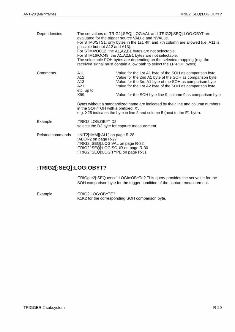
ANT-20 (Mainframe) :TRIG2[:SEQ]:LOG:OBYT?
:TRIG2[:SEQ]:LOG:OBYT?
:TRIGger2[:SEQuence]:LOGic:OBYTe? This query provides the set value for the SOH comparison byte for the trigger condition of the capture measurement.
Dependencies The set values of :TRIG2[:SEQ]:LOG:VAL and :TRIG2[:SEQ]:LOG:OBYT are evaluated for the trigger source VALue and NVALue.For STM0/STS1, only bytes in the 1st, 4th and 7th column are allowed (i.e. A11 is possible but not A12 and A13).For STM4/OC12, the A1,A2,B1 bytes are not selectable.For STM16/OC48, the A1,A2,B1 bytes are not selectable.The selectable POH bytes are depending on the selected mapping (e.g. the received signal must contain a low path to select the LP-POH bytes).
Comments A11A12A13A21etc. up toX99
Value for the 1st A1 byte of the SOH as comparison byteValue for the 2nd A1 byte of the SOH as comparison byteValue for the 3rd A1 byte of the SOH as comparison byteValue for the 1st A2 byte of the SOH as comparison byte
Value for the SOH byte line 9, column 9 as comparison byte
Bytes without a standardized name are indicated by their line and column numbers in the SOH/TOH with a prefixed ‘X’.e.g. X25 indicates the byte in line 2 and column 5 (next to the E1 byte).
Example :TRIG2:LOG:OBYT D2selects the D2 byte for capture measurement.
Related commands :INIT2[:IMM][:ALL] on page R-28:ABOR2 on page R-27:TRIG2[:SEQ]:LOG:VAL on page R-32:TRIG2[:SEQ]:LOG:SOUR on page R-30:TRIG2[:SEQ]:LOG:TYPE on page R-31
Example :TRIG2:LOG:OBYTE?K1K2 for the corresponding SOH comparison byte.
TRIGGER 2 subsystem R-29
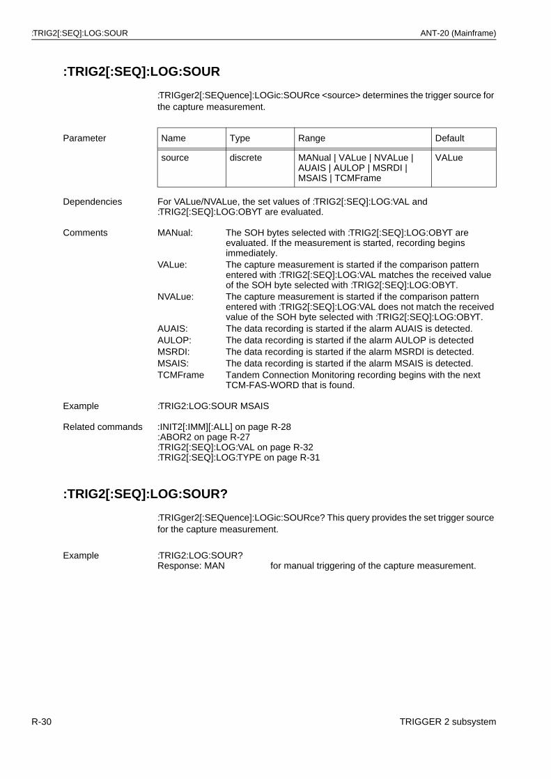
:TRIG2[:SEQ]:LOG:SOUR ANT-20 (Mainframe)
:TRIG2[:SEQ]:LOG:SOUR
:TRIGger2[:SEQuence]:LOGic:SOURce <source> determines the trigger source for the capture measurement.
:TRIG2[:SEQ]:LOG:SOUR?
:TRIGger2[:SEQuence]:LOGic:SOURce? This query provides the set trigger source for the capture measurement.
Parameter Name Type Range Default
source discrete MANual | VALue | NVALue | AUAIS | AULOP | MSRDI | MSAIS | TCMFrame
VALue
Dependencies For VALue/NVALue, the set values of :TRIG2[:SEQ]:LOG:VAL and :TRIG2[:SEQ]:LOG:OBYT are evaluated.
Comments MANual: The SOH bytes selected with :TRIG2[:SEQ]:LOG:OBYT are evaluated. If the measurement is started, recording begins immediately.
VALue: The capture measurement is started if the comparison pattern entered with :TRIG2[:SEQ]:LOG:VAL matches the received value of the SOH byte selected with :TRIG2[:SEQ]:LOG:OBYT.
NVALue: The capture measurement is started if the comparison pattern entered with :TRIG2[:SEQ]:LOG:VAL does not match the received value of the SOH byte selected with :TRIG2[:SEQ]:LOG:OBYT.
AUAIS: The data recording is started if the alarm AUAIS is detected.AULOP: The data recording is started if the alarm AULOP is detectedMSRDI: The data recording is started if the alarm MSRDI is detected.MSAIS: The data recording is started if the alarm MSAIS is detected.TCMFrame Tandem Connection Monitoring recording begins with the next
TCM-FAS-WORD that is found.
Example :TRIG2:LOG:SOUR MSAIS
Related commands :INIT2[:IMM][:ALL] on page R-28:ABOR2 on page R-27:TRIG2[:SEQ]:LOG:VAL on page R-32:TRIG2[:SEQ]:LOG:TYPE on page R-31
Example :TRIG2:LOG:SOUR?Response: MAN for manual triggering of the capture measurement.
R-30 TRIGGER 2 subsystem
ANT-20 (Mainframe) :TRIG2[:SEQ]:LOG:TYPE
:TRIG2[:SEQ]:LOG:TYPE
:TRIGger2[:SEQuence]:LOGic:TYPE <value> determines the time frame for data recording, referred to the trigger time point of the capture measurement.
:TRIG2[:SEQ]:LOG:TYPE?
:TRIGger2[:SEQuence]:LOGic:TYPE? This query provides the set value of the recording time frame for the capture measurement.
Parameter Name Type Range Default
value discrete AFTer AFTer
Dependencies None
Comments AFTer: The recording time frame of the capture measurement begins after the trigger.
Example :TRIG2:LOG:TYPE AFT
Related commands :INIT2[:IMM][:ALL] on page R-28:ABOR2 on page R-27:TRIG2[:SEQ]:LOG:SOUR on page R-30:TRIG2[:SEQ]:LOG:VAL? on page R-32:TRIG2[:SEQ]:LOG:OBYT on page R-28
Example :TRIG2:LOG:TYPE?Response: AFT for recording after the trigger event.
TRIGGER 2 subsystem R-31
:TRIG2[:SEQ]:LOG:VAL ANT-20 (Mainframe)
:TRIG2[:SEQ]:LOG:VAL
:TRIGger2[:SEQuence]:LOGic:VALue <pattern> determines the comparison pattern with which an SOH byte set with :TRIG2[:SEQ]:LOG:OBYT is compared to attain the trigger condition of the capture measurement.
:TRIG2[:SEQ]:LOG:VAL?
:TRIGger2[:SEQuence]:LOGic:VALue? This query provides the set value of the comparison pattern for the trigger condition of the capture measurement.
Parameter Name Type Range Default
pattern string String with the allowable characters “0” | “1” | “X” | “x” ,16 characters long.
“XXXXXXXXXXXXXXXX”
Dependencies The pattern set here is evaluated only for :TRIG2[:SEQ]:LOG:SOUR = VALue or NVALue.
Comments pattern: Only the characters “0”, “1”, “X”, “x” are allowed.A length of 16 characters is required.For 1 byte capture, only the first 8 characters are valid.
“X” | “x”: This bit position is irrelevant for the trigger condition.“1’’ A logical 1 is necessary at this bit position to attain the trigger
condition.“0’’ A logical 0 is necessary at this bit position to attain the trigger
condition.After the trigger condition is attained, the comparison value set here is no longer relevant, all subsequent byte changes are recorded regardless of the comparison value!
Example :TRIG2:LOG:VAL “XXXXXXXXXXXXXX01”For K1K2 capture, Bit0 is set to 1 and Bit1 to 0 as the trigger condition.:TRIG2:LOG:VAL “XXXXXX01XXXXXXXX”For 1 byte capture, Bit0 is set to 1 and Bit1 to 0 as the trigger condition since only the first 8 characters are relevant.
Related commands :INIT2[:IMM][:ALL] on page R-28:ABOR2 on page R-27:TRIG2[:SEQ]:LOG:TYPE on page R-31:TRIG2[:SEQ]:LOG:SOUR on page R-30:TRIG2[:SEQ]:LOG:OBYT on page R-28
Example :TRIG2:LOG:VAL?Response: “XXXXXXXX0011X001” for the corresponding comparison pattern.
R-32 TRIGGER 2 subsystem
ANT-20 (Mainframe) :ABOR3
6 TRIGGER 3 subsystem
The Trigger 3 subsystem is used to start and stop the capture process for a complete homogeneous SDH overhead fetch result. The following are required: Signal structure STM16/OC48 and options BN 3035/91.53, BN 3035/91.54 or BN 3035/91.59 (STM16c/OC48c hardware options).
:ABOR3
:ABORt3 halts the capture process started with :INIT3.
:INIT3[:IMM][:ALL]
:INITiate3[:IMMediate][:ALL] starts the capture process.
Parameter None
Dependencies This command works only if the capture process has been previously activated using :INIT3[:IMM][:ALL] on page R-33.
Example :ABOR3
Related commands :INIT3[:IMM][:ALL] on page R-33
Parameter None
Dependencies None
Comments :INIT3 starts the capture process for a complete homogeneous SDH overhead fetch result.
Example :INIT3
Related commands :ABOR3 on page R-33:FETC[:ARR][:DATA][:TEL][:SDH]:OVER:CPARt[i]? on page R-416:FETC:SCAL[:DATA][:TEL][:SDH]:OVER:CPARt[i]? on page R-426
TRIGGER 3 subsystem R-33

:INIT3[:IMM][:ALL] ANT-20 (Mainframe)
Notes:
R-34 TRIGGER 3 subsystem
ANT-20 (Mainframe) :OUTP:CLOC[1]:DIV[:STAT]
7 OUTPUT subsystem
:OUTP:CLOC[1]:DIV[:STAT]
:OUTPut:CLOCk[1]:DIVider[:STATe] <state> switches the clock output divider for port [24] on or off.
:OUTP:CLOC[1]:DIV[:STAT]?
This query provides the status of the clock output divider.
Parameter Name Type Range Default
state boolean ON | OFF | 0 | 1 OFF
Dependencies Is only valid if [:SENS]:DATA[:TEL]:SDH:RATE = STM4.
A setting = ON is mandatory for STM-4 Wander measurements in conjunction with the Jitter Module for options BN 3035/90.67 or O.172 BN 3035/90.86 with firmware release 7.0 or later (not possible for ABT-20 devices).
A setting = ON is mandatory for STM-4 JITTER measurements in conjunction with the Jitter Module ONLY for option O.172 BN 3035/90.86 with firmware release 7.0 or later (not possible for ABT-20 devices).
A setting = OFF is mandatory for STM-4 JITTER measurements in conjunction with the Jitter Module ONLY for option BN 3035/90.67 with firmware release earlier than 7.0 (not possible for ABT-20 devices).
Comments ON | 1: The STM4 clock divider is switched on producing a 155 Mbit/s clock signal at port [24] instead of the normal 622 Mbit/s. The setting in conjunction with the Jitter Module is explained above.
OFF | 0: Output divider off.The setting in conjunction with the Jitter Module is explained above.
Example :OUTP:CLOC:DIV ON switches the clock output divider on.
Related commands [:SENS]:DATA[:TEL]:SDH:RATE on page R-370
On Jitter Module: [:SENS]:DATA[:TEL]:RATE = STM4; [:SENS]:MODE.
Example :OUTP:CLOC:DIV?Response: 1 if the clock output divider is switched on.
OUTPUT subsystem R-35
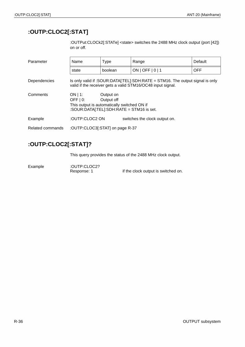
:OUTP:CLOC2[:STAT] ANT-20 (Mainframe)
:OUTP:CLOC2[:STAT]
:OUTPut:CLOCk2[:STATe] <state> switches the 2488 MHz clock output (port [42]) on or off.
:OUTP:CLOC2[:STAT]?
This query provides the status of the 2488 MHz clock output.
Parameter Name Type Range Default
state boolean ON | OFF | 0 | 1 OFF
Dependencies Is only valid if :SOUR:DATA[:TEL]:SDH:RATE = STM16. The output signal is only valid if the receiver gets a valid STM16/OC48 input signal.
Comments ON | 1: Output onOFF | 0: Output offThis output is automatically switched ON if :SOUR:DATA[:TEL]:SDH:RATE = STM16 is set.
Example :OUTP:CLOC2 ON switches the clock output on.
Related commands :OUTP:CLOC3[:STAT] on page R-37
Example :OUTP:CLOC2?Response: 1 if the clock output is switched on.
R-36 OUTPUT subsystem
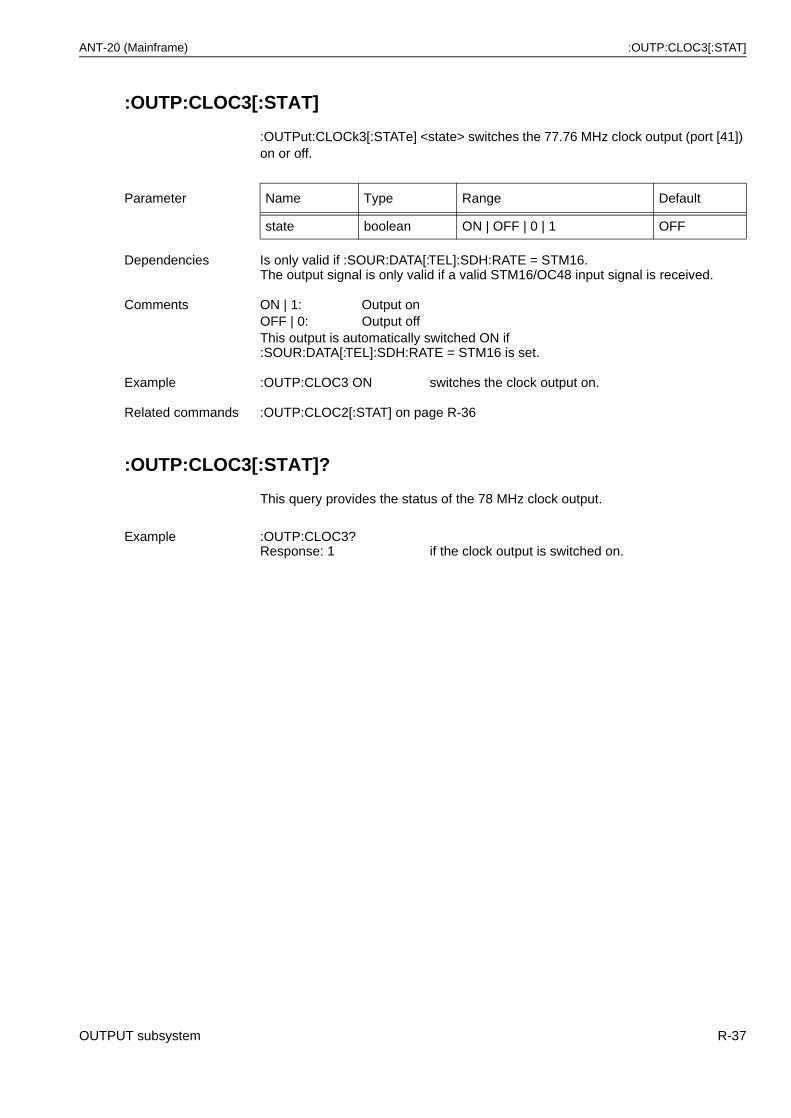
ANT-20 (Mainframe) :OUTP:CLOC3[:STAT]
:OUTP:CLOC3[:STAT]
:OUTPut:CLOCk3[:STATe] <state> switches the 77.76 MHz clock output (port [41]) on or off.
:OUTP:CLOC3[:STAT]?
This query provides the status of the 78 MHz clock output.
Parameter Name Type Range Default
state boolean ON | OFF | 0 | 1 OFF
Dependencies Is only valid if :SOUR:DATA[:TEL]:SDH:RATE = STM16.The output signal is only valid if a valid STM16/OC48 input signal is received.
Comments ON | 1: Output onOFF | 0: Output offThis output is automatically switched ON if :SOUR:DATA[:TEL]:SDH:RATE = STM16 is set.
Example :OUTP:CLOC3 ON switches the clock output on.
Related commands :OUTP:CLOC2[:STAT] on page R-36
Example :OUTP:CLOC3?Response: 1 if the clock output is switched on.
OUTPUT subsystem R-37
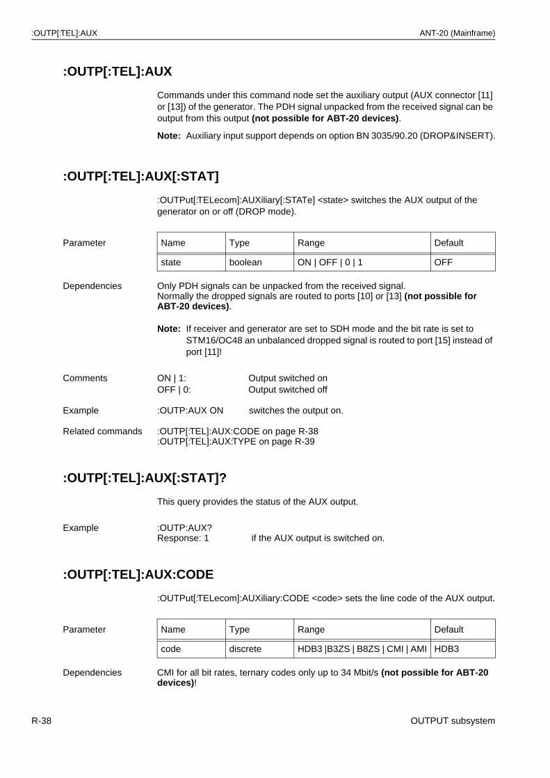
:OUTP[:TEL]:AUX ANT-20 (Mainframe)
:OUTP[:TEL]:AUX
Commands under this command node set the auxiliary output (AUX connector [11] or [13]) of the generator. The PDH signal unpacked from the received signal can be output from this output (not possible for ABT-20 devices).
Note: Auxiliary input support depends on option BN 3035/90.20 (DROP&INSERT).
:OUTP[:TEL]:AUX[:STAT]
:OUTPut[:TELecom]:AUXiliary[:STATe] <state> switches the AUX output of the generator on or off (DROP mode).
Note: If receiver and generator are set to SDH mode and the bit rate is set to STM16/OC48 an unbalanced dropped signal is routed to port [15] instead of port [11]!
:OUTP[:TEL]:AUX[:STAT]?
This query provides the status of the AUX output.
:OUTP[:TEL]:AUX:CODE
:OUTPut[:TELecom]:AUXiliary:CODE <code> sets the line code of the AUX output.
Parameter Name Type Range Default
state boolean ON | OFF | 0 | 1 OFF
Dependencies Only PDH signals can be unpacked from the received signal.Normally the dropped signals are routed to ports [10] or [13] (not possible for ABT-20 devices).
Comments ON | 1: Output switched onOFF | 0: Output switched off
Example :OUTP:AUX ON switches the output on.
Related commands :OUTP[:TEL]:AUX:CODE on page R-38:OUTP[:TEL]:AUX:TYPE on page R-39
Example :OUTP:AUX?Response: 1 if the AUX output is switched on.
Parameter Name Type Range Default
code discrete HDB3 |B3ZS | B8ZS | CMI | AMI HDB3
Dependencies CMI for all bit rates, ternary codes only up to 34 Mbit/s (not possible for ABT-20 devices)!
R-38 OUTPUT subsystem
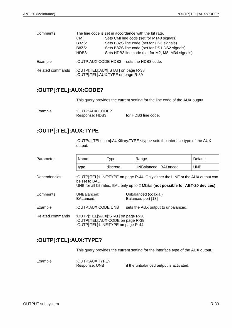
ANT-20 (Mainframe) :OUTP[:TEL]:AUX:CODE?
:OUTP[:TEL]:AUX:CODE?
This query provides the current setting for the line code of the AUX output.
:OUTP[:TEL]:AUX:TYPE
:OUTPut[:TELecom]:AUXiliary:TYPE <type> sets the interface type of the AUX output.
:OUTP[:TEL]:AUX:TYPE?
This query provides the current setting for the interface type of the AUX output.
Comments The line code is set in accordance with the bit rate.CMI: Sets CMI line code (set for M140 signals)B3ZS: Sets B3ZS line code (set for DS3 signals)B8ZS: Sets B8ZS line code (set for DS1,DS2 signals)HDB3: Sets HDB3 line code (set for M2, M8, M34 signals)
Example :OUTP:AUX:CODE HDB3 sets the HDB3 code.
Related commands :OUTP[:TEL]:AUX[:STAT] on page R-38:OUTP[:TEL]:AUX:TYPE on page R-39
Example :OUTP:AUX:CODE?Response: HDB3 for HDB3 line code.
Parameter Name Type Range Default
type discrete UNBalanced | BALanced UNB
Dependencies :OUTP[:TEL]:LINE:TYPE on page R-44! Only either the LINE or the AUX output can be set to BAL.UNB for all bit rates, BAL only up to 2 Mbit/s (not possible for ABT-20 devices).
Comments UNBalanced:BALanced:
Unbalanced (coaxial)Balanced port [13]
Example :OUTP:AUX:CODE UNB sets the AUX output to unbalanced.
Related commands :OUTP[:TEL]:AUX[:STAT] on page R-38:OUTP[:TEL]:AUX:CODE on page R-38:OUTP[:TEL]:LINE:TYPE on page R-44
Example :OUTP:AUX:TYPE?Response: UNB if the unbalanced output is activated.
OUTPUT subsystem R-39
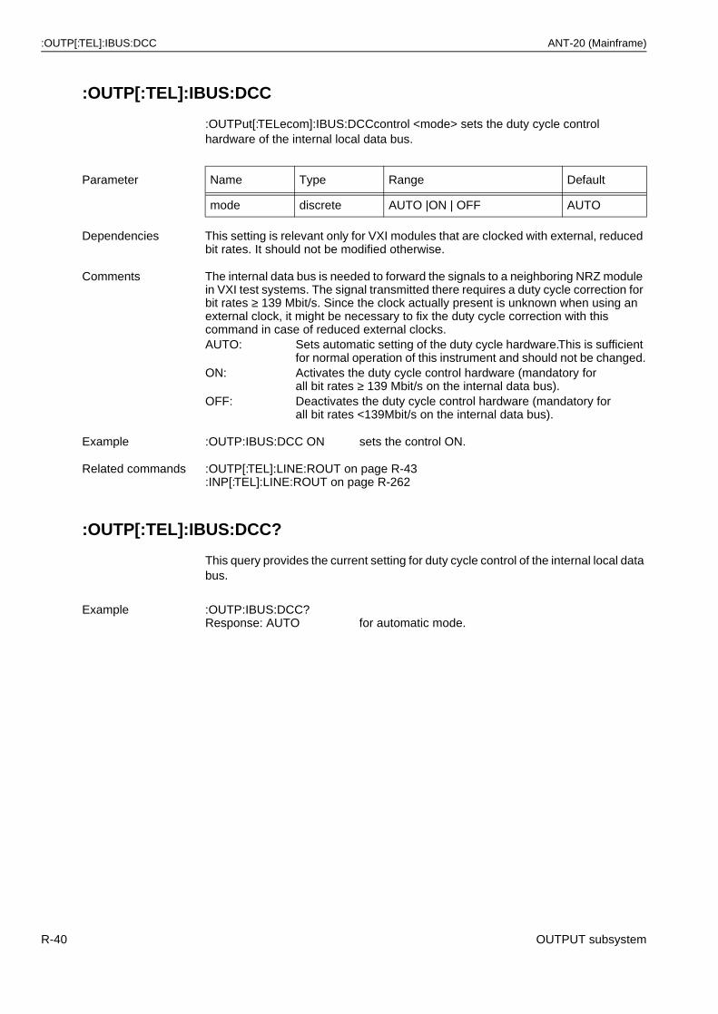
:OUTP[:TEL]:IBUS:DCC ANT-20 (Mainframe)
:OUTP[:TEL]:IBUS:DCC
:OUTPut[:TELecom]:IBUS:DCCcontrol <mode> sets the duty cycle control hardware of the internal local data bus.
:OUTP[:TEL]:IBUS:DCC?
This query provides the current setting for duty cycle control of the internal local data bus.
Parameter Name Type Range Default
mode discrete AUTO |ON | OFF AUTO
Dependencies This setting is relevant only for VXI modules that are clocked with external, reduced bit rates. It should not be modified otherwise.
Comments The internal data bus is needed to forward the signals to a neighboring NRZ module in VXI test systems. The signal transmitted there requires a duty cycle correction for bit rates ≥ 139 Mbit/s. Since the clock actually present is unknown when using an external clock, it might be necessary to fix the duty cycle correction with this command in case of reduced external clocks.AUTO: Sets automatic setting of the duty cycle hardware.This is sufficient
for normal operation of this instrument and should not be changed.ON: Activates the duty cycle control hardware (mandatory for
all bit rates ≥ 139 Mbit/s on the internal data bus).OFF: Deactivates the duty cycle control hardware (mandatory for
all bit rates <139Mbit/s on the internal data bus).
Example :OUTP:IBUS:DCC ON sets the control ON.
Related commands :OUTP[:TEL]:LINE:ROUT on page R-43:INP[:TEL]:LINE:ROUT on page R-262
Example :OUTP:IBUS:DCC?Response: AUTO for automatic mode.
R-40 OUTPUT subsystem
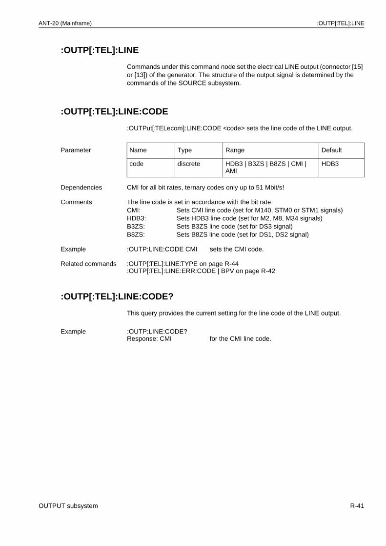
ANT-20 (Mainframe) :OUTP[:TEL]:LINE
:OUTP[:TEL]:LINE
Commands under this command node set the electrical LINE output (connector [15] or [13]) of the generator. The structure of the output signal is determined by the commands of the SOURCE subsystem.
:OUTP[:TEL]:LINE:CODE
:OUTPut[:TELecom]:LINE:CODE <code> sets the line code of the LINE output.
:OUTP[:TEL]:LINE:CODE?
This query provides the current setting for the line code of the LINE output.
Parameter Name Type Range Default
code discrete HDB3 | B3ZS | B8ZS | CMI | AMI
HDB3
Dependencies CMI for all bit rates, ternary codes only up to 51 Mbit/s!
Comments The line code is set in accordance with the bit rateCMI: Sets CMI line code (set for M140, STM0 or STM1 signals)HDB3: Sets HDB3 line code (set for M2, M8, M34 signals)B3ZS: Sets B3ZS line code (set for DS3 signal)B8ZS: Sets B8ZS line code (set for DS1, DS2 signal)
Example :OUTP:LINE:CODE CMI sets the CMI code.
Related commands :OUTP[:TEL]:LINE:TYPE on page R-44:OUTP[:TEL]:LINE:ERR:CODE | BPV on page R-42
Example :OUTP:LINE:CODE?Response: CMI for the CMI line code.
OUTPUT subsystem R-41
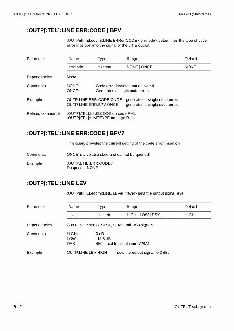
:OUTP[:TEL]:LINE:ERR:CODE | BPV ANT-20 (Mainframe)
:OUTP[:TEL]:LINE:ERR:CODE | BPV
:OUTPut[:TELecom]:LINE:ERRor:CODE <errmode> determines the type of code error insertion into the signal of the LINE output.
:OUTP[:TEL]:LINE:ERR:CODE | BPV?
This query provides the current setting of the code error insertion.
:OUTP[:TEL]:LINE:LEV
:OUTPut[:TELecom]:LINE:LEVel <level> sets the output signal level.
Parameter Name Type Range Default
errmode discrete NONE | ONCE NONE
Dependencies None
Comments NONE: Code error insertion not activated.ONCE: Generates a single code error.
Example OUTP:LINE:ERR:CODE ONCE generates a single code error.OUTP:LINE:ERR:BPV ONCE generates a single code error.
Related commands :OUTP[:TEL]:LINE:CODE on page R-41:OUTP[:TEL]:LINE:TYPE on page R-44
Comments ONCE is a volatile state and cannot be queried!
Example :OUTP:LINE:ERR:CODE?Response: NONE
Parameter Name Type Range Default
level discrete HIGH | LOW | DSX HIGH
Dependencies Can only be set for STS1, STM0 and DS3 signals.
Comments HIGH: 0 dBLOW: -13.8 dBDSX: 450 ft. cable simulation (728A)
Example OUTP:LINE:LEV HIGH sets the output signal to 0 dB.
R-42 OUTPUT subsystem
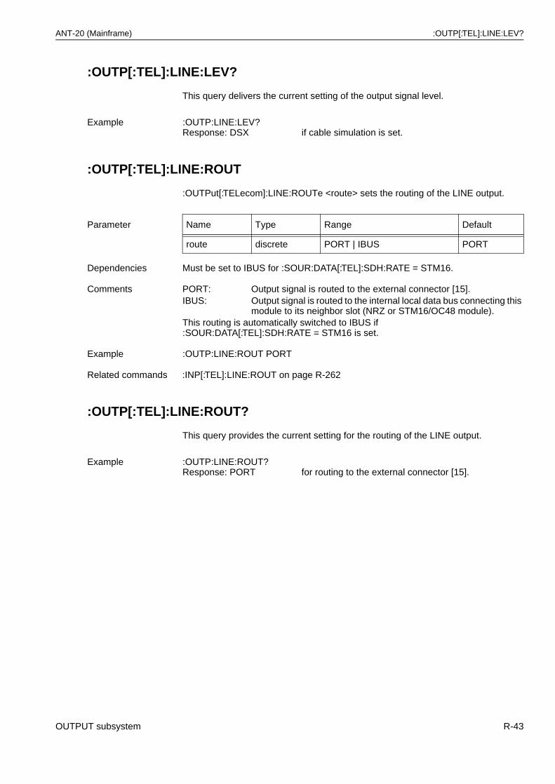
ANT-20 (Mainframe) :OUTP[:TEL]:LINE:LEV?
:OUTP[:TEL]:LINE:LEV?
This query delivers the current setting of the output signal level.
:OUTP[:TEL]:LINE:ROUT
:OUTPut[:TELecom]:LINE:ROUTe <route> sets the routing of the LINE output.
:OUTP[:TEL]:LINE:ROUT?
This query provides the current setting for the routing of the LINE output.
Example :OUTP:LINE:LEV?Response: DSX if cable simulation is set.
Parameter Name Type Range Default
route discrete PORT | IBUS PORT
Dependencies Must be set to IBUS for :SOUR:DATA[:TEL]:SDH:RATE = STM16.
Comments PORT: Output signal is routed to the external connector [15].IBUS: Output signal is routed to the internal local data bus connecting this
module to its neighbor slot (NRZ or STM16/OC48 module).This routing is automatically switched to IBUS if :SOUR:DATA[:TEL]:SDH:RATE = STM16 is set.
Example :OUTP:LINE:ROUT PORT
Related commands :INP[:TEL]:LINE:ROUT on page R-262
Example :OUTP:LINE:ROUT?Response: PORT for routing to the external connector [15].
OUTPUT subsystem R-43
:OUTP[:TEL]:LINE:TYPE ANT-20 (Mainframe)
:OUTP[:TEL]:LINE:TYPE
:OUTPut[:TELecom]:LINE:TYPE <type> sets the interface type of the LINE output.
:OUTP[:TEL]:LINE:TYPE?
This query provides the current setting for the interface type of the LINE output.
Parameter Name Type Range Default
route discrete UNB | BAL UNB
Dependencies UNB for all bit rates, BAL only up to 2Mbit/s.:OUTP[:TEL]:AUX:TYPE on page R-39! Only either the LINE or the AUX output can be set to BAL.
Comments UNBalanced: Unbalanced (coaxial)BALanced: Balanced port [13]
Example :OUTP:LINE:TYPE UNB sets the LINE output to unbalanced.
Related commands :OUTP[:TEL]:LINE:CODE on page R-41:OUTP[:TEL]:LINE:ERR:CODE | BPV on page R-42:OUTP[:TEL]:AUX:TYPE on page R-39
Example :OUTP:LINE:TYPE?Response: UNB if the unbalanced output is activated.
R-44 OUTPUT subsystem
ANT-20 (Mainframe) :OUTP[:TEL]:NRZ
:OUTP[:TEL]:NRZ
Commands under this command node set the electrical NRZ output (port[46]) of the generator for STM16 or OC48 signals.
Note: This output support depends on options BN 3035/90.5X (electrical STM16/OC48 interfaces).
:OUTP[:TEL]:NRZ[:STAT]
:OUTPut[:TELecom]:NRZ[:STATe] <state> switches the electrical output of the STM16 or OC48 generator (port[46]) on or off.
:OUTP[:TEL]:NRZ[:STAT]?
This query provides the status of the electrical STM16/OC48 output.
Parameter Name Type Range Default
state boolean ON | OFF | 0 | 1 OFF
Dependencies <state> = ON only valid if :SOUR:DATA[:TEL]:SOUR[:SOCK] = OPTIC.<state> = ON only valid if :SOUR:MODE = SDH.<state> = ON only valid if :SOUR:DATA[:TEL]:SDH:RATE = STM16.
Comments ON | 1: Output switched onOFF | 0: Output switched offThis output is automatically switched ON if :SOUR:DATA[:TEL]:SDH:RATE = STM16 is set.
Example :OUTP:NRZ ON switches the output on.
Related commands :OUTP[:TEL]:OPT2[:STAT] on page R-48
Example :OUTP:NRZ?Response: 1 if the electrical output is switched on.
OUTPUT subsystem R-45
:OUTP[:TEL]:OPT[1] ANT-20 (Mainframe)
:OUTP[:TEL]:OPT[1]
Commands under this command node set the optical output (port [18]) of the generator for STM0/1/4 or OC1/OC3/OC12 signals.
Note: Optical output support depends on options BN 3035/90.4X (optical interfaces).
:OUTP[:TEL]:OPT[1][:STAT]
:OUTPut[:TELecom]:OPTic[1][:STATe] <state> switches the optical output of the STM0/1/4 or OC1/OC3/OC12 generator (port [18]) on or off.
:OUTP[:TEL]:OPT[1][:STAT]?
This query provides the status of the optical output.
Parameter Name Type Range Default
state boolean ON | OFF | 0 | 1 OFF
Dependencies <state> = ON only valid if :SOUR:DATA[:TEL]:SOUR[:SOCK] = OPTIC.<state> = ON only valid if :SOUR:MODE = SDH.<state> = ON only valid if :SOUR:DATA[:TEL]:SDH:RATE = STM0|STM1|STM4.
Comments ON | 1: Output switched on (LASER ON)OFF | 0: Output switched off (LASER OFF)
Example :OUTP:OPT ON switches the output on.
Related commands :OUTP[:TEL]:OPT[1]:WLEN on page R-47
Example :OUTP:OPT?Response: 1 if the optical output is switched on.
R-46 OUTPUT subsystem
ANT-20 (Mainframe) :OUTP[:TEL]:OPT[1]:WLEN
:OUTP[:TEL]:OPT[1]:WLEN
:OUTPut[:TELecom]:OPTic[1]:WLENgth <wavelength> sets the wavelength of the optical STM0/1/4 or OC1/OC3/OC12 output (port [18]).
:OUTP[:TEL]:OPT[1]:WLEN?
This query provides the wavelength setting of the optical output.
Parameter Name Type Range Default
wavelength discrete W1310 | W1550 W1310
Dependencies The corresponding option must be available.Value is set to W1550 if option W1310 is not available when optical signal is selected.
Comments W1310: 1310 nm generator wavelengthW1550: 1550 nm generator wavelength
Example :OUTP:OPT:WLEN W1550 sets the wavelength to 1550 nm.
Related commands :OUTP[:TEL]:OPT[1][:STAT] on page R-46
Example :OUTP:OPT:WLEN?Response: W1310
OUTPUT subsystem R-47
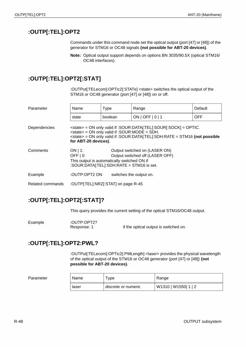
:OUTP[:TEL]:OPT2 ANT-20 (Mainframe)
:OUTP[:TEL]:OPT2
Commands under this command node set the optical output (port [47] or [48]) of the generator for STM16 or OC48 signals (not possible for ABT-20 devices).
Note: Optical output support depends on options BN 3035/90.5X (optical STM16/OC48 interfaces).
:OUTP[:TEL]:OPT2[:STAT]
:OUTPut[:TELecom]:OPTic2[:STATe] <state> switches the optical output of the STM16 or OC48 generator (port [47] or [48]) on or off.
:OUTP[:TEL]:OPT2[:STAT]?
This query provides the current setting of the optical STM16/OC48 output.
:OUTP[:TEL]:OPT2:PWL?
:OUTPut[:TELecom]:OPTic2[:PWLength] <laser> provides the physical wavelength of the optical output of the STM16 or OC48 generator (port [47] or [48]) (not possible for ABT-20 devices).
Parameter Name Type Range Default
state boolean ON | OFF | 0 | 1 OFF
Dependencies <state> = ON only valid if :SOUR:DATA[:TEL]:SOUR[:SOCK] = OPTIC.<state> = ON only valid if :SOUR:MODE = SDH.<state> = ON only valid if :SOUR:DATA[:TEL]:SDH:RATE = STM16 (not possible for ABT-20 devices).
Comments ON | 1: Output switched on (LASER ON)OFF | 0: Output switched off (LASER OFF)This output is automatically switched ON if :SOUR:DATA[:TEL]:SDH:RATE = STM16 is set.
Example :OUTP:OPT2 ON switches the output on.
Related commands :OUTP[:TEL]:NRZ[:STAT] on page R-45
Example :OUTP:OPT2?Response: 1 if the optical output is switched on.
Parameter Name Type Range
laser discrete or numeric W1310 | W1550| 1 | 2
R-48 OUTPUT subsystem
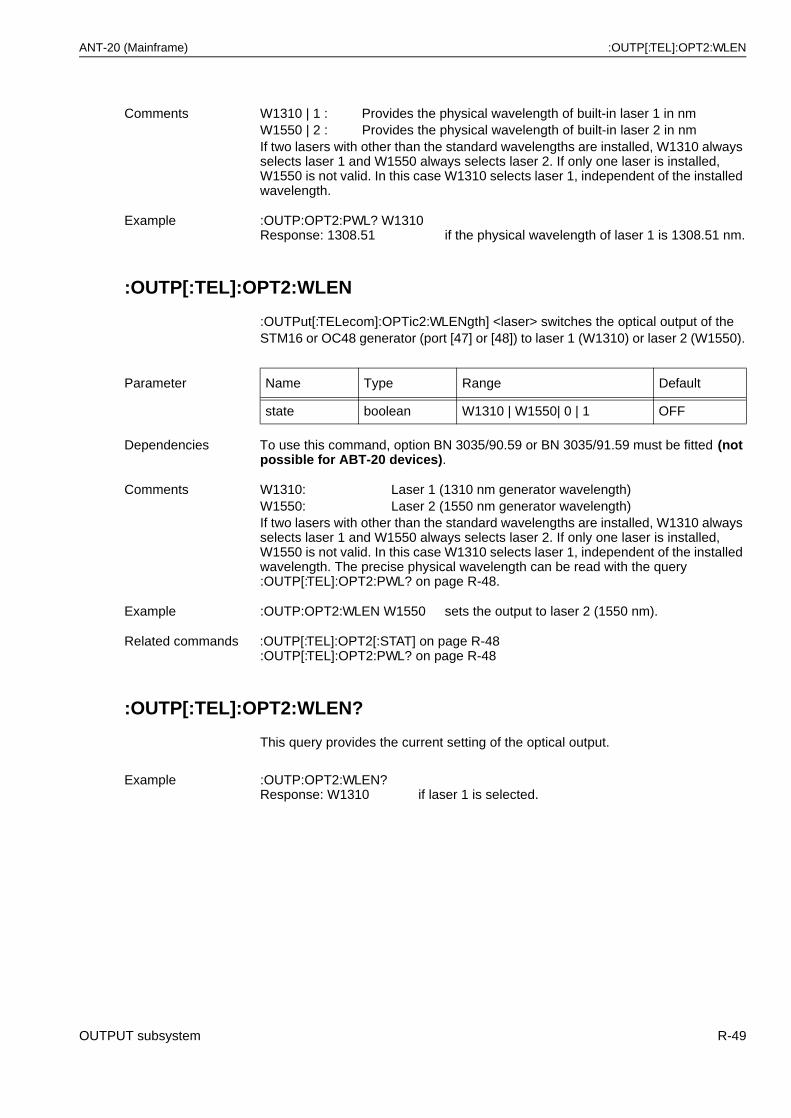
ANT-20 (Mainframe) :OUTP[:TEL]:OPT2:WLEN
:OUTP[:TEL]:OPT2:WLEN
:OUTPut[:TELecom]:OPTic2:WLENgth] <laser> switches the optical output of the STM16 or OC48 generator (port [47] or [48]) to laser 1 (W1310) or laser 2 (W1550).
:OUTP[:TEL]:OPT2:WLEN?
This query provides the current setting of the optical output.
Comments W1310 | 1 : Provides the physical wavelength of built-in laser 1 in nmW1550 | 2 : Provides the physical wavelength of built-in laser 2 in nmIf two lasers with other than the standard wavelengths are installed, W1310 always selects laser 1 and W1550 always selects laser 2. If only one laser is installed, W1550 is not valid. In this case W1310 selects laser 1, independent of the installed wavelength.
Example :OUTP:OPT2:PWL? W1310Response: 1308.51 if the physical wavelength of laser 1 is 1308.51 nm.
Parameter Name Type Range Default
state boolean W1310 | W1550| 0 | 1 OFF
Dependencies To use this command, option BN 3035/90.59 or BN 3035/91.59 must be fitted (not possible for ABT-20 devices).
Comments W1310: Laser 1 (1310 nm generator wavelength)W1550: Laser 2 (1550 nm generator wavelength)If two lasers with other than the standard wavelengths are installed, W1310 always selects laser 1 and W1550 always selects laser 2. If only one laser is installed, W1550 is not valid. In this case W1310 selects laser 1, independent of the installed wavelength. The precise physical wavelength can be read with the query:OUTP[:TEL]:OPT2:PWL? on page R-48.
Example :OUTP:OPT2:WLEN W1550 sets the output to laser 2 (1550 nm).
Related commands :OUTP[:TEL]:OPT2[:STAT] on page R-48:OUTP[:TEL]:OPT2:PWL? on page R-48
Example :OUTP:OPT2:WLEN?Response: W1310 if laser 1 is selected.
OUTPUT subsystem R-49
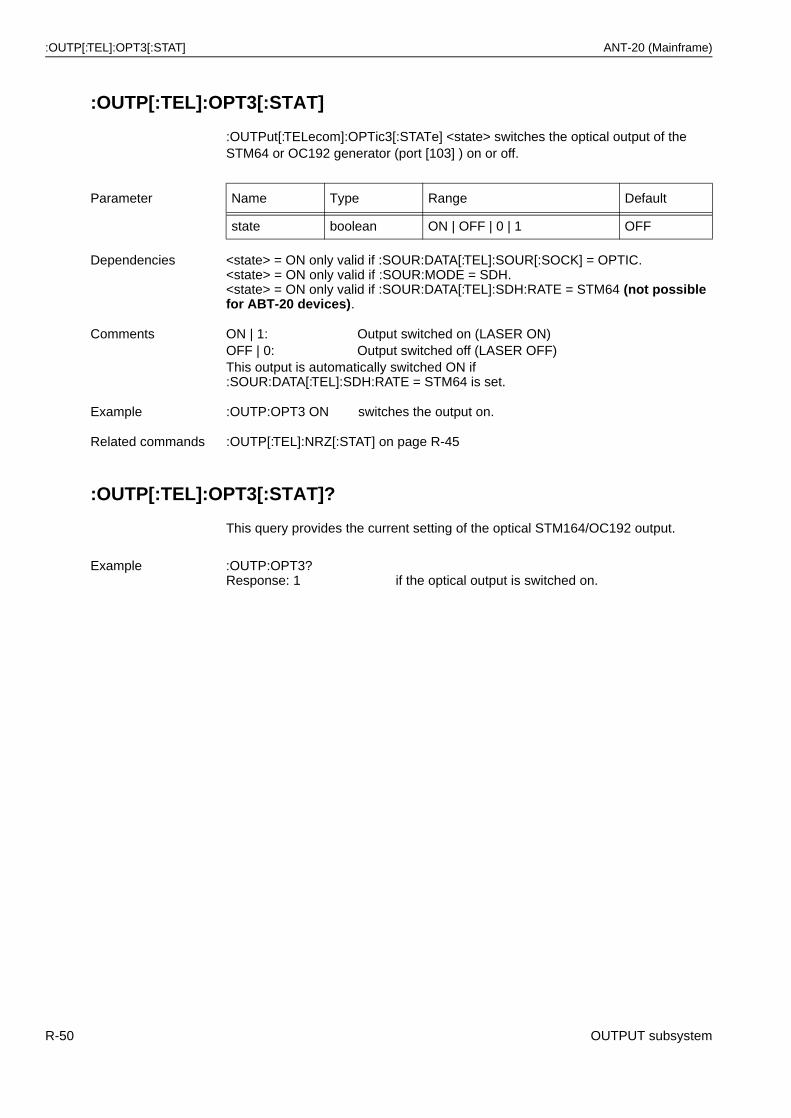
:OUTP[:TEL]:OPT3[:STAT] ANT-20 (Mainframe)
:OUTP[:TEL]:OPT3[:STAT]
:OUTPut[:TELecom]:OPTic3[:STATe] <state> switches the optical output of the STM64 or OC192 generator (port [103] ) on or off.
:OUTP[:TEL]:OPT3[:STAT]?
This query provides the current setting of the optical STM164/OC192 output.
Parameter Name Type Range Default
state boolean ON | OFF | 0 | 1 OFF
Dependencies <state> = ON only valid if :SOUR:DATA[:TEL]:SOUR[:SOCK] = OPTIC.<state> = ON only valid if :SOUR:MODE = SDH.<state> = ON only valid if :SOUR:DATA[:TEL]:SDH:RATE = STM64 (not possible for ABT-20 devices).
Comments ON | 1: Output switched on (LASER ON)OFF | 0: Output switched off (LASER OFF)This output is automatically switched ON if :SOUR:DATA[:TEL]:SDH:RATE = STM64 is set.
Example :OUTP:OPT3 ON switches the output on.
Related commands :OUTP[:TEL]:NRZ[:STAT] on page R-45
Example :OUTP:OPT3?Response: 1 if the optical output is switched on.
R-50 OUTPUT subsystem
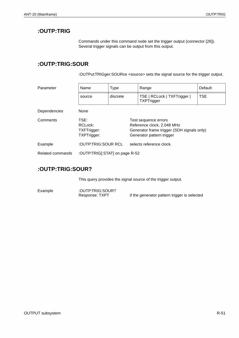
ANT-20 (Mainframe) :OUTP:TRIG
:OUTP:TRIG
Commands under this command node set the trigger output (connector [26]). Several trigger signals can be output from this output.
:OUTP:TRIG:SOUR
:OUTPut:TRIGger:SOURce <source> sets the signal source for the trigger output.
:OUTP:TRIG:SOUR?
This query provides the signal source of the trigger output.
Parameter Name Type Range Default
source discrete TSE | RCLock | TXFTrigger | TXPTrigger
TSE
Dependencies None
Comments TSE: Test sequence errorsRCLock: Reference clock, 2.048 MHzTXFTrigger: Generator frame trigger (SDH signals only)TXPTrigger: Generator pattern trigger
Example :OUTP:TRIG:SOUR RCL selects reference clock.
Related commands :OUTP:TRIG[:STAT] on page R-52
Example :OUTP:TRIG:SOUR?Response: TXPT if the generator pattern trigger is selected
OUTPUT subsystem R-51
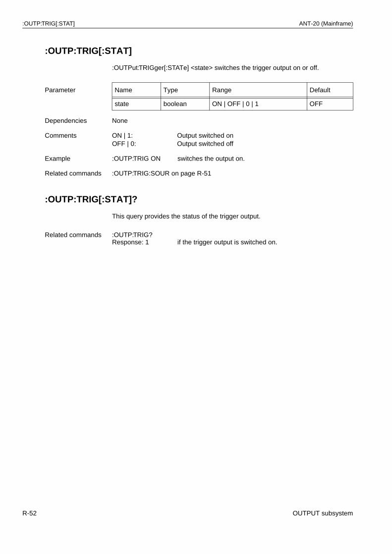
:OUTP:TRIG[:STAT] ANT-20 (Mainframe)
:OUTP:TRIG[:STAT]
:OUTPut:TRIGger[:STATe] <state> switches the trigger output on or off.
:OUTP:TRIG[:STAT]?
This query provides the status of the trigger output.
Parameter Name Type Range Default
state boolean ON | OFF | 0 | 1 OFF
Dependencies None
Comments ON | 1: Output switched onOFF | 0: Output switched off
Example :OUTP:TRIG ON switches the output on.
Related commands :OUTP:TRIG:SOUR on page R-51
Related commands :OUTP:TRIG?Response: 1 if the trigger output is switched on.
R-52 OUTPUT subsystem
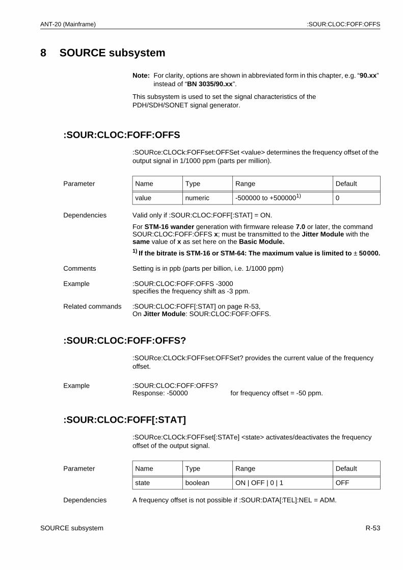
ANT-20 (Mainframe) :SOUR:CLOC:FOFF:OFFS
8 SOURCE subsystem
Note: For clarity, options are shown in abbreviated form in this chapter, e.g. “90.xx” instead of “BN 3035/90.xx”.
This subsystem is used to set the signal characteristics of the PDH/SDH/SONET signal generator.
:SOUR:CLOC:FOFF:OFFS
:SOURce:CLOCk:FOFFset:OFFSet <value> determines the frequency offset of the output signal in 1/1000 ppm (parts per million).
:SOUR:CLOC:FOFF:OFFS?
:SOURce:CLOCk:FOFFset:OFFSet? provides the current value of the frequency offset.
:SOUR:CLOC:FOFF[:STAT]
:SOURce:CLOCk:FOFFset[:STATe] <state> activates/deactivates the frequency offset of the output signal.
Parameter Name Type Range Default
value numeric -500000 to +5000001) 0
Dependencies Valid only if :SOUR:CLOC:FOFF[:STAT] = ON.
For STM-16 wander generation with firmware release 7.0 or later, the command SOUR:CLOC:FOFF:OFFS x; must be transmitted to the Jitter Module with the same value of x as set here on the Basic Module. 1) If the bitrate is STM-16 or STM-64: The maximum value is limited to ± 50000.
Comments Setting is in ppb (parts per billion, i.e. 1/1000 ppm)
Example :SOUR:CLOC:FOFF:OFFS -3000specifies the frequency shift as -3 ppm.
Related commands :SOUR:CLOC:FOFF[:STAT] on page R-53,On Jitter Module: SOUR:CLOC:FOFF:OFFS.
Example :SOUR:CLOC:FOFF:OFFS?Response: -50000 for frequency offset = -50 ppm.
Parameter Name Type Range Default
state boolean ON | OFF | 0 | 1 OFF
Dependencies A frequency offset is not possible if :SOUR:DATA[:TEL]:NEL = ADM.
SOURCE subsystem R-53
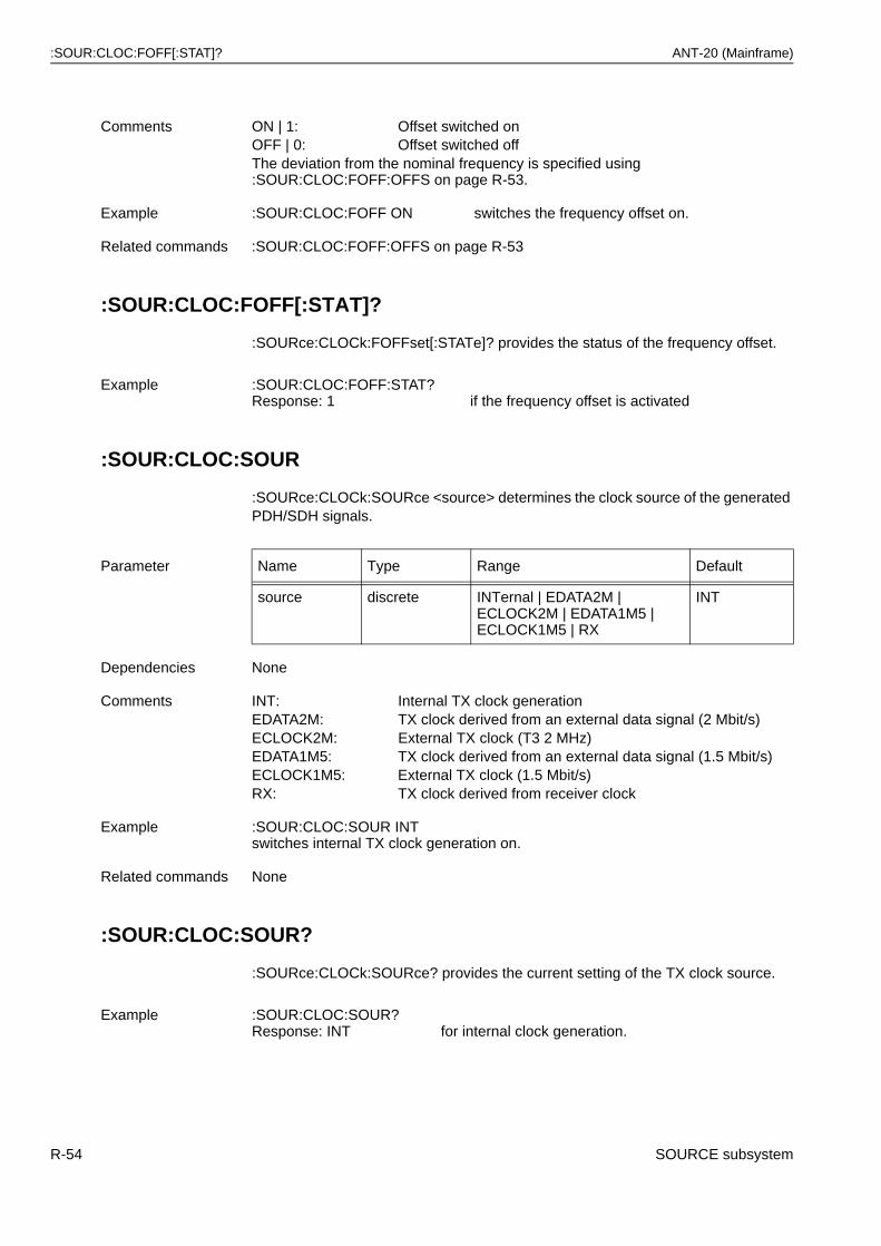
:SOUR:CLOC:FOFF[:STAT]? ANT-20 (Mainframe)
:SOUR:CLOC:FOFF[:STAT]?
:SOURce:CLOCk:FOFFset[:STATe]? provides the status of the frequency offset.
:SOUR:CLOC:SOUR
:SOURce:CLOCk:SOURce <source> determines the clock source of the generated PDH/SDH signals.
:SOUR:CLOC:SOUR?
:SOURce:CLOCk:SOURce? provides the current setting of the TX clock source.
Comments ON | 1: Offset switched onOFF | 0: Offset switched offThe deviation from the nominal frequency is specified using :SOUR:CLOC:FOFF:OFFS on page R-53.
Example :SOUR:CLOC:FOFF ON switches the frequency offset on.
Related commands :SOUR:CLOC:FOFF:OFFS on page R-53
Example :SOUR:CLOC:FOFF:STAT?Response: 1 if the frequency offset is activated
Parameter Name Type Range Default
source discrete INTernal | EDATA2M | ECLOCK2M | EDATA1M5 | ECLOCK1M5 | RX
INT
Dependencies None
Comments INT: Internal TX clock generationEDATA2M: TX clock derived from an external data signal (2 Mbit/s)ECLOCK2M: External TX clock (T3 2 MHz)EDATA1M5: TX clock derived from an external data signal (1.5 Mbit/s)ECLOCK1M5: External TX clock (1.5 Mbit/s)RX: TX clock derived from receiver clock
Example :SOUR:CLOC:SOUR INTswitches internal TX clock generation on.
Related commands None
Example :SOUR:CLOC:SOUR?Response: INT for internal clock generation.
R-54 SOURCE subsystem
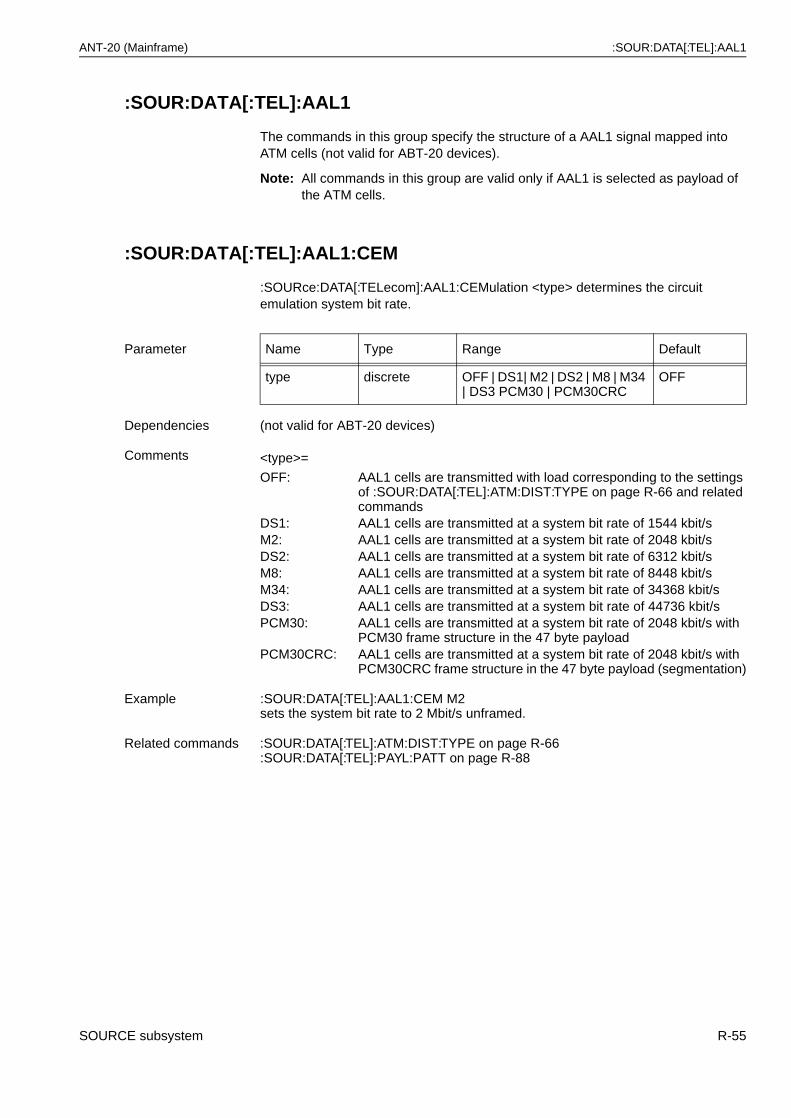
ANT-20 (Mainframe) :SOUR:DATA[:TEL]:AAL1
:SOUR:DATA[:TEL]:AAL1
The commands in this group specify the structure of a AAL1 signal mapped into ATM cells (not valid for ABT-20 devices).
Note: All commands in this group are valid only if AAL1 is selected as payload of the ATM cells.
:SOUR:DATA[:TEL]:AAL1:CEM
:SOURce:DATA[:TELecom]:AAL1:CEMulation <type> determines the circuit emulation system bit rate.
Parameter Name Type Range Default
type discrete OFF | DS1| M2 | DS2 | M8 | M34 | DS3 PCM30 | PCM30CRC
OFF
Dependencies (not valid for ABT-20 devices)
Comments <type>=
OFF: AAL1 cells are transmitted with load corresponding to the settings of :SOUR:DATA[:TEL]:ATM:DIST:TYPE on page R-66 and related commands
DS1: AAL1 cells are transmitted at a system bit rate of 1544 kbit/sM2: AAL1 cells are transmitted at a system bit rate of 2048 kbit/sDS2: AAL1 cells are transmitted at a system bit rate of 6312 kbit/sM8: AAL1 cells are transmitted at a system bit rate of 8448 kbit/sM34: AAL1 cells are transmitted at a system bit rate of 34368 kbit/sDS3: AAL1 cells are transmitted at a system bit rate of 44736 kbit/sPCM30: AAL1 cells are transmitted at a system bit rate of 2048 kbit/s with
PCM30 frame structure in the 47 byte payloadPCM30CRC: AAL1 cells are transmitted at a system bit rate of 2048 kbit/s with
PCM30CRC frame structure in the 47 byte payload (segmentation)
Example :SOUR:DATA[:TEL]:AAL1:CEM M2 sets the system bit rate to 2 Mbit/s unframed.
Related commands :SOUR:DATA[:TEL]:ATM:DIST:TYPE on page R-66:SOUR:DATA[:TEL]:PAYL:PATT on page R-88
SOURCE subsystem R-55
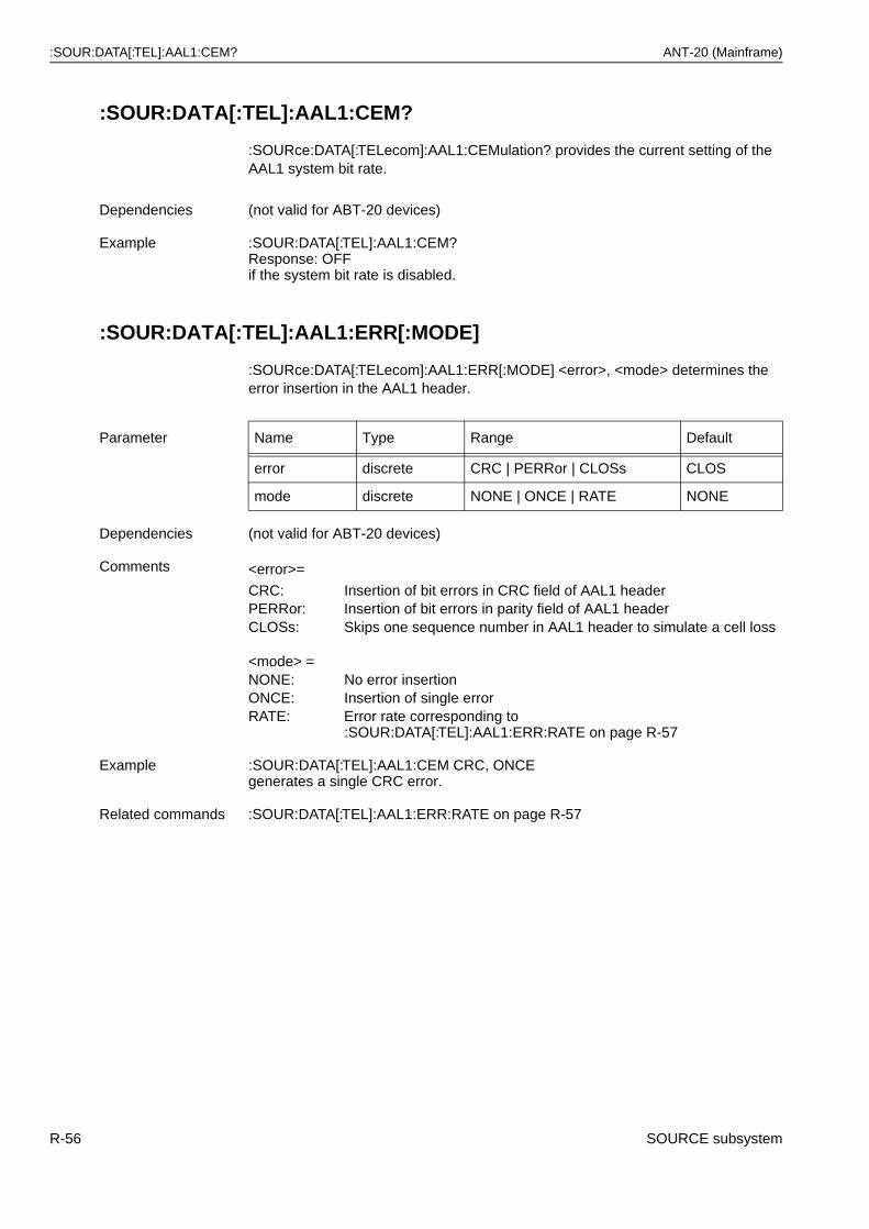
:SOUR:DATA[:TEL]:AAL1:CEM? ANT-20 (Mainframe)
:SOUR:DATA[:TEL]:AAL1:CEM?
:SOURce:DATA[:TELecom]:AAL1:CEMulation? provides the current setting of the AAL1 system bit rate.
:SOUR:DATA[:TEL]:AAL1:ERR[:MODE]
:SOURce:DATA[:TELecom]:AAL1:ERR[:MODE] <error>, <mode> determines the error insertion in the AAL1 header.
Dependencies (not valid for ABT-20 devices)
Example :SOUR:DATA[:TEL]:AAL1:CEM?Response: OFFif the system bit rate is disabled.
Parameter Name Type Range Default
error discrete CRC | PERRor | CLOSs CLOS
mode discrete NONE | ONCE | RATE NONE
Dependencies (not valid for ABT-20 devices)
Comments <error>=
CRC: Insertion of bit errors in CRC field of AAL1 headerPERRor: Insertion of bit errors in parity field of AAL1 headerCLOSs: Skips one sequence number in AAL1 header to simulate a cell loss
<mode> =NONE: No error insertionONCE: Insertion of single errorRATE: Error rate corresponding to
:SOUR:DATA[:TEL]:AAL1:ERR:RATE on page R-57
Example :SOUR:DATA[:TEL]:AAL1:CEM CRC, ONCE generates a single CRC error.
Related commands :SOUR:DATA[:TEL]:AAL1:ERR:RATE on page R-57
R-56 SOURCE subsystem
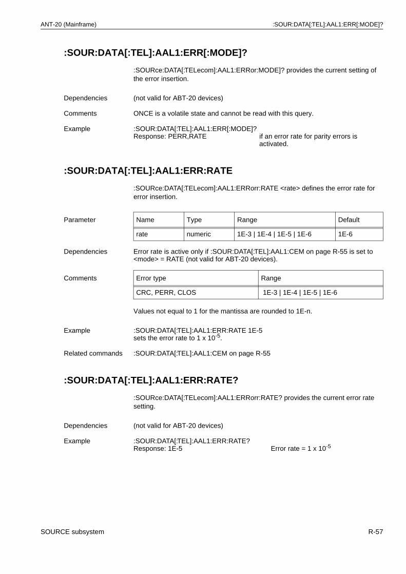
ANT-20 (Mainframe) :SOUR:DATA[:TEL]:AAL1:ERR[:MODE]?
:SOUR:DATA[:TEL]:AAL1:ERR[:MODE]?
:SOURce:DATA[:TELecom]:AAL1:ERRor:MODE]? provides the current setting of the error insertion.
:SOUR:DATA[:TEL]:AAL1:ERR:RATE
:SOURce:DATA[:TELecom]:AAL1:ERRorr:RATE <rate> defines the error rate for error insertion.
Values not equal to 1 for the mantissa are rounded to 1E-n.
:SOUR:DATA[:TEL]:AAL1:ERR:RATE?
:SOURce:DATA[:TELecom]:AAL1:ERRorr:RATE? provides the current error rate setting.
Dependencies (not valid for ABT-20 devices)
Comments ONCE is a volatile state and cannot be read with this query.
Example :SOUR:DATA[:TEL]:AAL1:ERR[:MODE]?Response: PERR,RATE if an error rate for parity errors is
activated.
Parameter Name Type Range Default
rate numeric 1E-3 | 1E-4 | 1E-5 | 1E-6 1E-6
Dependencies Error rate is active only if :SOUR:DATA[:TEL]:AAL1:CEM on page R-55 is set to <mode> = RATE (not valid for ABT-20 devices).
Comments Error type Range
CRC, PERR, CLOS 1E-3 | 1E-4 | 1E-5 | 1E-6
Example :SOUR:DATA[:TEL]:AAL1:ERR:RATE 1E-5 sets the error rate to 1 x 10⁻⁵.
Related commands :SOUR:DATA[:TEL]:AAL1:CEM on page R-55
Dependencies (not valid for ABT-20 devices)
Example :SOUR:DATA[:TEL]:AAL1:ERR:RATE?Response: 1E-5 Error rate = 1 x 10⁻⁵
SOURCE subsystem R-57
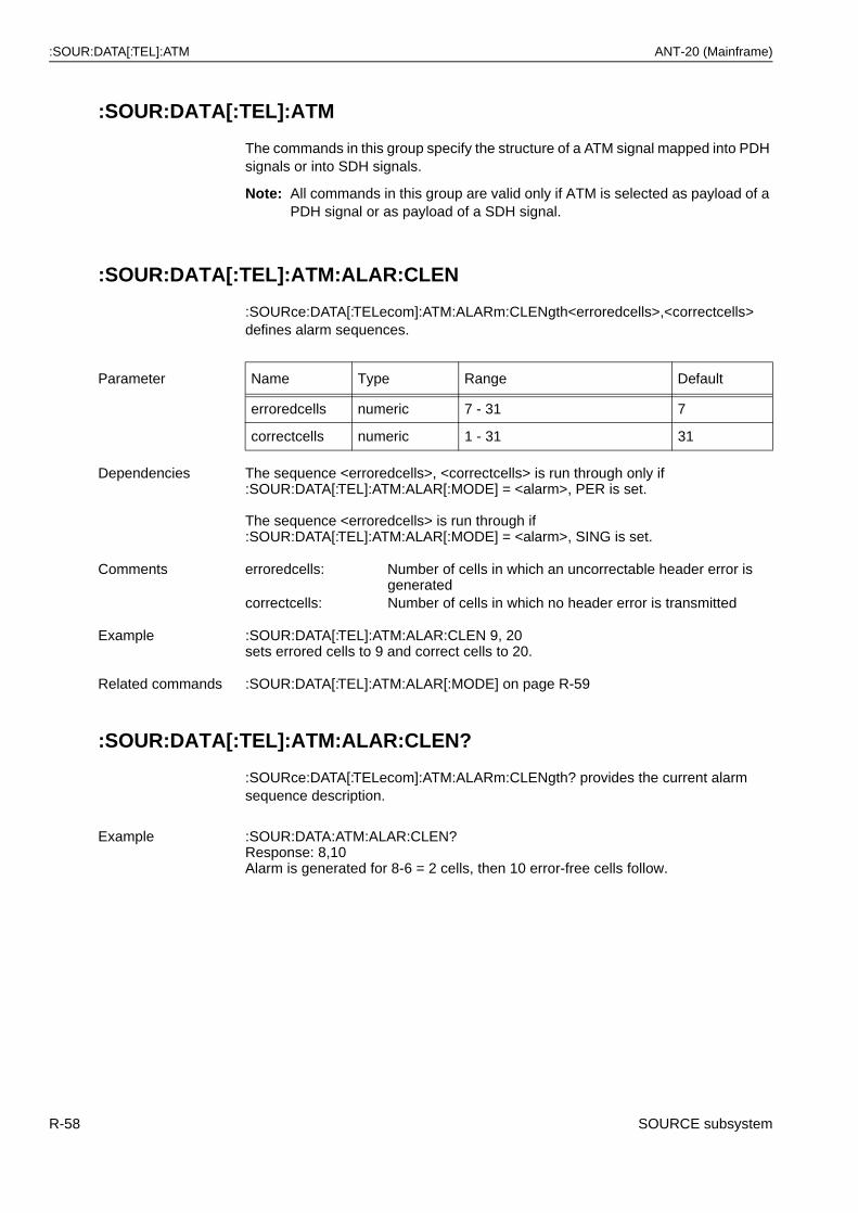
:SOUR:DATA[:TEL]:ATM ANT-20 (Mainframe)
:SOUR:DATA[:TEL]:ATM
The commands in this group specify the structure of a ATM signal mapped into PDH signals or into SDH signals.
Note: All commands in this group are valid only if ATM is selected as payload of a PDH signal or as payload of a SDH signal.
:SOUR:DATA[:TEL]:ATM:ALAR:CLEN
:SOURce:DATA[:TELecom]:ATM:ALARm:CLENgth<erroredcells>,<correctcells> defines alarm sequences.
:SOUR:DATA[:TEL]:ATM:ALAR:CLEN?
:SOURce:DATA[:TELecom]:ATM:ALARm:CLENgth? provides the current alarm sequence description.
Parameter Name Type Range Default
erroredcells numeric 7 - 31 7
correctcells numeric 1 - 31 31
Dependencies The sequence <erroredcells>, <correctcells> is run through only if :SOUR:DATA[:TEL]:ATM:ALAR[:MODE] = <alarm>, PER is set.
The sequence <erroredcells> is run through if :SOUR:DATA[:TEL]:ATM:ALAR[:MODE] = <alarm>, SING is set.
Comments erroredcells: Number of cells in which an uncorrectable header error is generated
correctcells: Number of cells in which no header error is transmitted
Example :SOUR:DATA[:TEL]:ATM:ALAR:CLEN 9, 20 sets errored cells to 9 and correct cells to 20.
Related commands :SOUR:DATA[:TEL]:ATM:ALAR[:MODE] on page R-59
Example :SOUR:DATA:ATM:ALAR:CLEN?Response: 8,10Alarm is generated for 8-6 = 2 cells, then 10 error-free cells follow.
R-58 SOURCE subsystem

ANT-20 (Mainframe) :SOUR:DATA[:TEL]:ATM:ALAR[:MODE]
:SOUR:DATA[:TEL]:ATM:ALAR[:MODE]
:SOURce:DATA:[TELecom]:ATM:ALARm[:MODE] <alarm>, <mode> determines the alarm insertion.
Parameter Name Type Range Default
alarm discrete LOCD | EVPAIS | EVPRDI | EVCAIS | EVCRDI | EV2AIS | EV2RDI
LOCD
mode discrete NONE | ONCE | CONTinuous | SINGle | PERiodical
NONE
Dependencies None
Comments <alarm> =
LOCD: Loss of cell delineationEVPAIS: Sends F4 OAM cell carrying AIS end to end
(not possible for ABT-20 devices)EVPRDI: Sends F4 OAM cell carrying RDI end to end
(not possible for ABT-20 devices)EVCAIS: Sends F5 OAM cell carrying AIS end to end
(not possible for ABT-20 devices)EVCRDI: Sends F5 OAM cell carrying RDI end to end
(not possible for ABT-20 devices)EV2AIS: Sends both EVPAIS and EVCAIS
(not possible for ABT-20 devices)EV2RDI: Sends both EVPRDI and EVCRDI
(not possible for ABT-20 devices)<mode> =NONE: No alarm insertionONCE: Insertion of single alarm for
:SOUR:DATA[:TEL]:ATM:ALAR[:MODE] = LOCD7 cells are transmitted with uncorrectable header errors
CONTinuous: Continuous alarm insertionSINGle: Insertion of an alarm for the duration <erroredcells>
corresponding to SOUR:DATA[:TEL]:ATM:ALAR:CLENPERiodical: Periodic execution of an alarm sequence corresponding to
:SOUR:DATA[:TEL]:ATM:ALAR:CLEN <erroredcells>,<correctcells>
Example :SOUR:DATA[:TEL]:ATM:ALAR[:MODE] LOCD,CONT activates the “LOCD” alarm in “continuous” mode.
Related commands :SOUR:DATA[:TEL]:ATM:ALAR:CLEN on page R-58
SOURCE subsystem R-59

:SOUR:DATA[:TEL]:ATM:ALAR[:MODE]? ANT-20 (Mainframe)
:SOUR:DATA[:TEL]:ATM:ALAR[:MODE]?
:SOURce:DATA[:TELecom]:ATM:ALARm[:MODE]? provides the current setting of the alarm insertion.
:SOUR:DATA[:TEL]:ATM:DIST:BURS:BLO
:SOURce:DATA[:TELecom]:ATM:DISTribution:BURSt:BLOad <burstload> determines the relative load of the burst in the measurement channel (burst load).
:SOUR:DATA[:TEL]:ATM:DIST:BURS:BLO?
:SOURce:DATA[:TELecom]:ATM:DISTribution:BURSt:BLOad? provides the current setting of the relative load of the burst.
Comments ONCE is a volatile state and cannot be read.
Example :SOUR:DATA:ATM:ALAR?Response: LOCD,CONT
if continuous insertion of LOCD is activated.
Parameter Name Type Range Default
burstload numeric 1 - 100 100
0.25 - 25 (if VC4_4C (STS12C_SPE) ATM is selected)
25
Dependencies The setting is valid only for :SOUR:DATA[:TEL]:ATM:DIST:TYPE = BURS (not valid for ABT-20 devices).
Comments Setting is in %. The unit % is not specified.The resolution is 1 %.Burst load 80 % means a burst with 80 % load for a duration of :SOUR:DATA[:TEL]:ATM:DIST:BURS:BLEN <burstlength> cells.
Example :SOUR:DATA[:TEL]:ATM:DIST:BURS:BLO 100sets the burst load to 100 %.
Related commands :SOUR:DATA[:TEL]:ATM:DIST:BURS:BLEN on page R-61:SOUR:DATA[:TEL]:ATM:DIST:BURS:BPER on page R-61:SOUR:DATA[:TEL]:ATM:DIST:CONS:LOAD on page R-62:SOUR:DATA[:TEL]:ATM:DIST:EQU:CDIS on page R-64:SOUR:DATA[:TEL]:ATM:DIST:TYPE on page R-66
Dependencies (not valid for ABT-20 devices)
Example :SOUR:DATA:ATM:DIST:BURS:BLO?Response: 100 for burst load = 100 %.
R-60 SOURCE subsystem
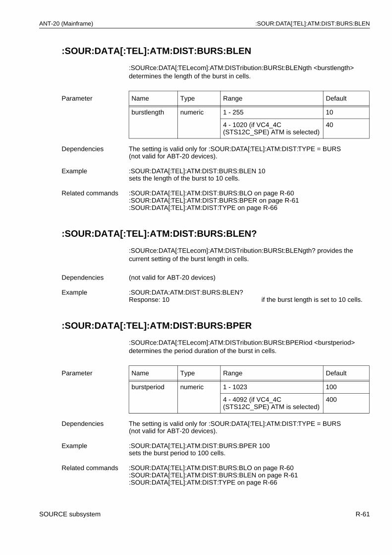
ANT-20 (Mainframe) :SOUR:DATA[:TEL]:ATM:DIST:BURS:BLEN
:SOUR:DATA[:TEL]:ATM:DIST:BURS:BLEN
:SOURce:DATA[:TELecom]:ATM:DISTribution:BURSt:BLENgth <burstlength> determines the length of the burst in cells.
:SOUR:DATA[:TEL]:ATM:DIST:BURS:BLEN?
:SOURce:DATA[:TELecom]:ATM:DISTribution:BURSt:BLENgth? provides the current setting of the burst length in cells.
:SOUR:DATA[:TEL]:ATM:DIST:BURS:BPER
:SOURce:DATA[:TELecom]:ATM:DISTribution:BURSt:BPERiod <burstperiod> determines the period duration of the burst in cells.
Parameter Name Type Range Default
burstlength numeric 1 - 255 10
4 - 1020 (if VC4_4C (STS12C_SPE) ATM is selected)
40
Dependencies The setting is valid only for :SOUR:DATA[:TEL]:ATM:DIST:TYPE = BURS (not valid for ABT-20 devices).
Example :SOUR:DATA[:TEL]:ATM:DIST:BURS:BLEN 10sets the length of the burst to 10 cells.
Related commands :SOUR:DATA[:TEL]:ATM:DIST:BURS:BLO on page R-60:SOUR:DATA[:TEL]:ATM:DIST:BURS:BPER on page R-61:SOUR:DATA[:TEL]:ATM:DIST:TYPE on page R-66
Dependencies (not valid for ABT-20 devices)
Example :SOUR:DATA:ATM:DIST:BURS:BLEN?Response: 10 if the burst length is set to 10 cells.
Parameter Name Type Range Default
burstperiod numeric 1 - 1023 100
4 - 4092 (if VC4_4C (STS12C_SPE) ATM is selected)
400
Dependencies The setting is valid only for :SOUR:DATA[:TEL]:ATM:DIST:TYPE = BURS (not valid for ABT-20 devices).
Example :SOUR:DATA[:TEL]:ATM:DIST:BURS:BPER 100 sets the burst period to 100 cells.
Related commands :SOUR:DATA[:TEL]:ATM:DIST:BURS:BLO on page R-60:SOUR:DATA[:TEL]:ATM:DIST:BURS:BLEN on page R-61:SOUR:DATA[:TEL]:ATM:DIST:TYPE on page R-66
SOURCE subsystem R-61
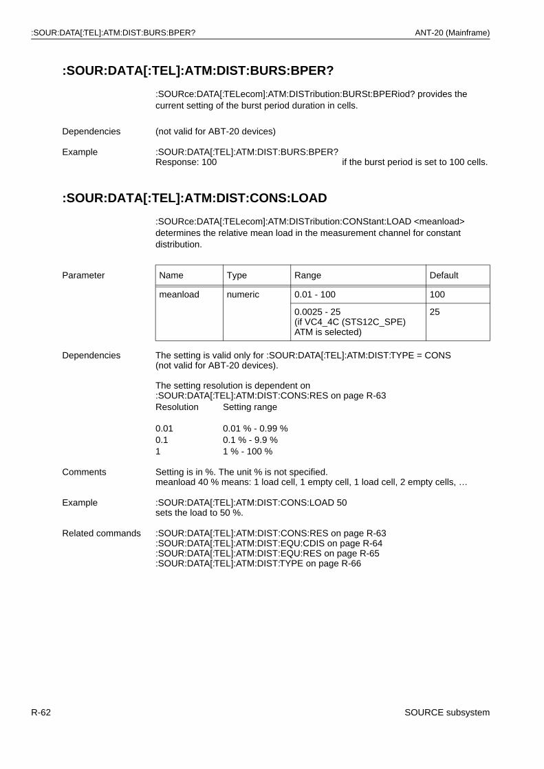
:SOUR:DATA[:TEL]:ATM:DIST:BURS:BPER? ANT-20 (Mainframe)
:SOUR:DATA[:TEL]:ATM:DIST:BURS:BPER?
:SOURce:DATA[:TELecom]:ATM:DISTribution:BURSt:BPERiod? provides the current setting of the burst period duration in cells.
:SOUR:DATA[:TEL]:ATM:DIST:CONS:LOAD
:SOURce:DATA[:TELecom]:ATM:DISTribution:CONStant:LOAD <meanload> determines the relative mean load in the measurement channel for constant distribution.
Dependencies (not valid for ABT-20 devices)
Example :SOUR:DATA[:TEL]:ATM:DIST:BURS:BPER?Response: 100 if the burst period is set to 100 cells.
Parameter Name Type Range Default
meanload numeric 0.01 - 100 100
0.0025 - 25(if VC4_4C (STS12C_SPE) ATM is selected)
25
Dependencies The setting is valid only for :SOUR:DATA[:TEL]:ATM:DIST:TYPE = CONS (not valid for ABT-20 devices).
The setting resolution is dependent on :SOUR:DATA[:TEL]:ATM:DIST:CONS:RES on page R-63Resolution Setting range
0.01 0.01 % - 0.99 %0.1 0.1 % - 9.9 %1 1 % - 100 %
Comments Setting is in %. The unit % is not specified.meanload 40 % means: 1 load cell, 1 empty cell, 1 load cell, 2 empty cells, …
Example :SOUR:DATA[:TEL]:ATM:DIST:CONS:LOAD 50 sets the load to 50 %.
Related commands :SOUR:DATA[:TEL]:ATM:DIST:CONS:RES on page R-63:SOUR:DATA[:TEL]:ATM:DIST:EQU:CDIS on page R-64:SOUR:DATA[:TEL]:ATM:DIST:EQU:RES on page R-65:SOUR:DATA[:TEL]:ATM:DIST:TYPE on page R-66
R-62 SOURCE subsystem
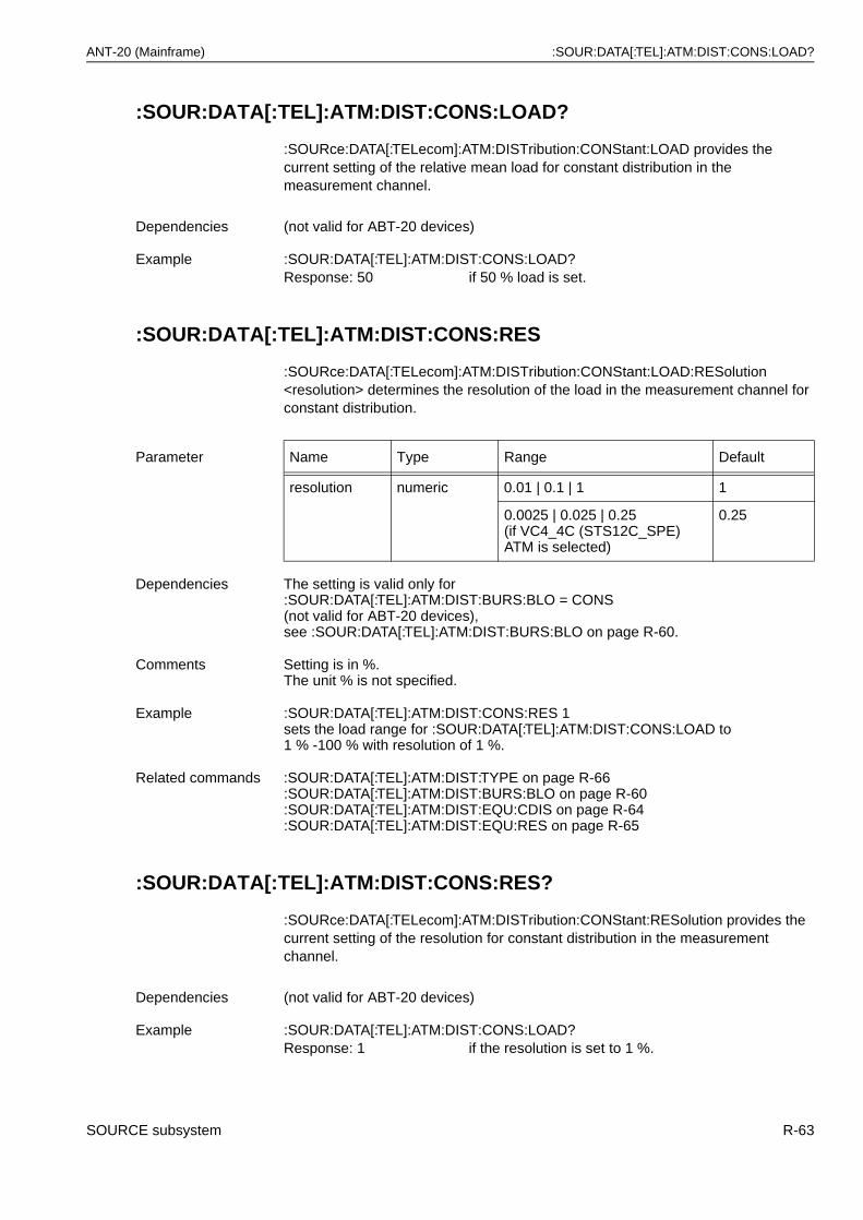
ANT-20 (Mainframe) :SOUR:DATA[:TEL]:ATM:DIST:CONS:LOAD?
:SOUR:DATA[:TEL]:ATM:DIST:CONS:LOAD?
:SOURce:DATA[:TELecom]:ATM:DISTribution:CONStant:LOAD provides the current setting of the relative mean load for constant distribution in the measurement channel.
:SOUR:DATA[:TEL]:ATM:DIST:CONS:RES
:SOURce:DATA[:TELecom]:ATM:DISTribution:CONStant:LOAD:RESolution <resolution> determines the resolution of the load in the measurement channel for constant distribution.
:SOUR:DATA[:TEL]:ATM:DIST:CONS:RES?
:SOURce:DATA[:TELecom]:ATM:DISTribution:CONStant:RESolution provides the current setting of the resolution for constant distribution in the measurement channel.
Dependencies (not valid for ABT-20 devices)
Example :SOUR:DATA[:TEL]:ATM:DIST:CONS:LOAD?Response: 50 if 50 % load is set.
Parameter Name Type Range Default
resolution numeric 0.01 | 0.1 | 1 1
0.0025 | 0.025 | 0.25(if VC4_4C (STS12C_SPE) ATM is selected)
0.25
Dependencies The setting is valid only for :SOUR:DATA[:TEL]:ATM:DIST:BURS:BLO = CONS(not valid for ABT-20 devices),see :SOUR:DATA[:TEL]:ATM:DIST:BURS:BLO on page R-60.
Comments Setting is in %. The unit % is not specified.
Example :SOUR:DATA[:TEL]:ATM:DIST:CONS:RES 1sets the load range for :SOUR:DATA[:TEL]:ATM:DIST:CONS:LOAD to1 % -100 % with resolution of 1 %.
Related commands :SOUR:DATA[:TEL]:ATM:DIST:TYPE on page R-66:SOUR:DATA[:TEL]:ATM:DIST:BURS:BLO on page R-60:SOUR:DATA[:TEL]:ATM:DIST:EQU:CDIS on page R-64:SOUR:DATA[:TEL]:ATM:DIST:EQU:RES on page R-65
Dependencies (not valid for ABT-20 devices)
Example :SOUR:DATA[:TEL]:ATM:DIST:CONS:LOAD?Response: 1 if the resolution is set to 1 %.
SOURCE subsystem R-63
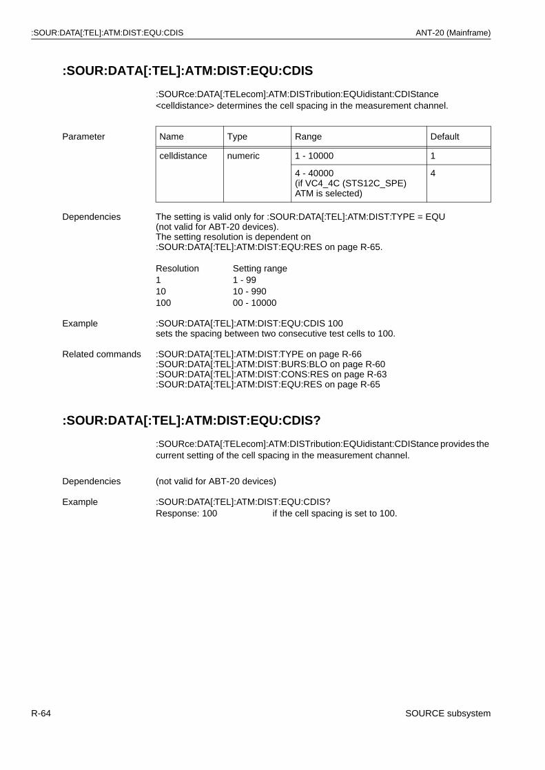
:SOUR:DATA[:TEL]:ATM:DIST:EQU:CDIS ANT-20 (Mainframe)
:SOUR:DATA[:TEL]:ATM:DIST:EQU:CDIS
:SOURce:DATA[:TELecom]:ATM:DISTribution:EQUidistant:CDIStance <celldistance> determines the cell spacing in the measurement channel.
:SOUR:DATA[:TEL]:ATM:DIST:EQU:CDIS?
:SOURce:DATA[:TELecom]:ATM:DISTribution:EQUidistant:CDIStance provides the current setting of the cell spacing in the measurement channel.
Parameter Name Type Range Default
celldistance numeric 1 - 10000 1
4 - 40000(if VC4_4C (STS12C_SPE) ATM is selected)
4
Dependencies The setting is valid only for :SOUR:DATA[:TEL]:ATM:DIST:TYPE = EQU (not valid for ABT-20 devices).The setting resolution is dependent on :SOUR:DATA[:TEL]:ATM:DIST:EQU:RES on page R-65.
Resolution Setting range1 1 - 9910 10 - 990100 00 - 10000
Example :SOUR:DATA[:TEL]:ATM:DIST:EQU:CDIS 100 sets the spacing between two consecutive test cells to 100.
Related commands :SOUR:DATA[:TEL]:ATM:DIST:TYPE on page R-66:SOUR:DATA[:TEL]:ATM:DIST:BURS:BLO on page R-60:SOUR:DATA[:TEL]:ATM:DIST:CONS:RES on page R-63:SOUR:DATA[:TEL]:ATM:DIST:EQU:RES on page R-65
Dependencies (not valid for ABT-20 devices)
Example :SOUR:DATA[:TEL]:ATM:DIST:EQU:CDIS?Response: 100 if the cell spacing is set to 100.
R-64 SOURCE subsystem
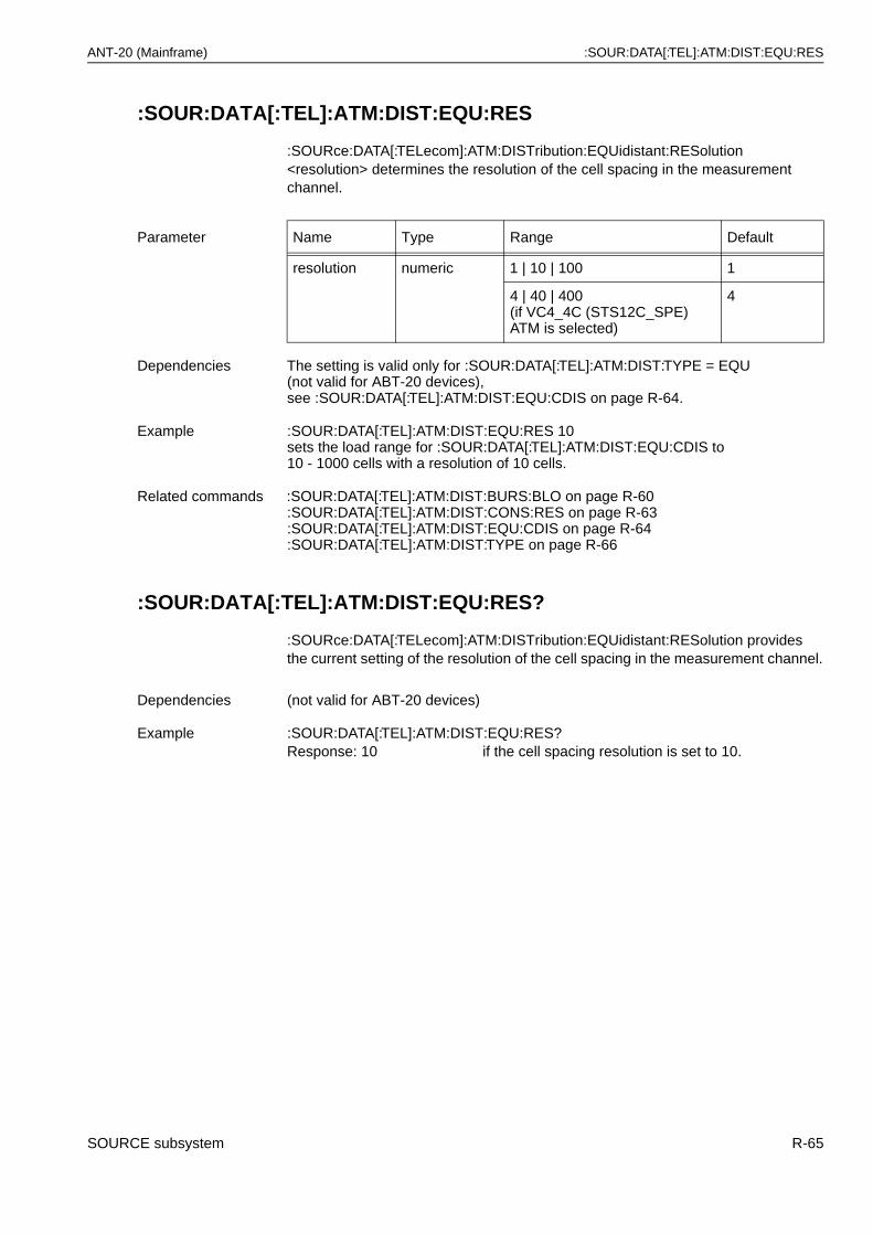
ANT-20 (Mainframe) :SOUR:DATA[:TEL]:ATM:DIST:EQU:RES
:SOUR:DATA[:TEL]:ATM:DIST:EQU:RES
:SOURce:DATA[:TELecom]:ATM:DISTribution:EQUidistant:RESolution <resolution> determines the resolution of the cell spacing in the measurement channel.
:SOUR:DATA[:TEL]:ATM:DIST:EQU:RES?
:SOURce:DATA[:TELecom]:ATM:DISTribution:EQUidistant:RESolution provides the current setting of the resolution of the cell spacing in the measurement channel.
Parameter Name Type Range Default
resolution numeric 1 | 10 | 100 1
4 | 40 | 400(if VC4_4C (STS12C_SPE) ATM is selected)
4
Dependencies The setting is valid only for :SOUR:DATA[:TEL]:ATM:DIST:TYPE = EQU (not valid for ABT-20 devices),see :SOUR:DATA[:TEL]:ATM:DIST:EQU:CDIS on page R-64.
Example :SOUR:DATA[:TEL]:ATM:DIST:EQU:RES 10 sets the load range for :SOUR:DATA[:TEL]:ATM:DIST:EQU:CDIS to10 - 1000 cells with a resolution of 10 cells.
Related commands :SOUR:DATA[:TEL]:ATM:DIST:BURS:BLO on page R-60:SOUR:DATA[:TEL]:ATM:DIST:CONS:RES on page R-63:SOUR:DATA[:TEL]:ATM:DIST:EQU:CDIS on page R-64:SOUR:DATA[:TEL]:ATM:DIST:TYPE on page R-66
Dependencies (not valid for ABT-20 devices)
Example :SOUR:DATA[:TEL]:ATM:DIST:EQU:RES?Response: 10 if the cell spacing resolution is set to 10.
SOURCE subsystem R-65
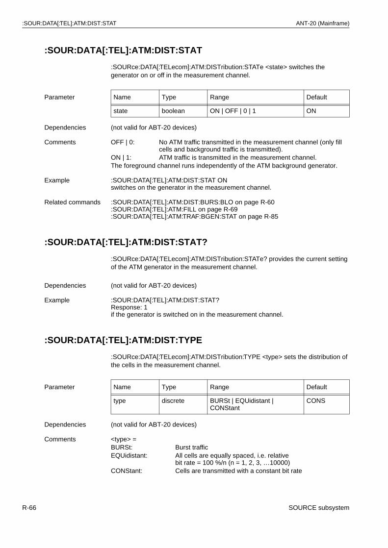
:SOUR:DATA[:TEL]:ATM:DIST:STAT ANT-20 (Mainframe)
:SOUR:DATA[:TEL]:ATM:DIST:STAT
:SOURce:DATA[:TELecom]:ATM:DISTribution:STATe <state> switches the generator on or off in the measurement channel.
:SOUR:DATA[:TEL]:ATM:DIST:STAT?
:SOURce:DATA[:TELecom]:ATM:DISTribution:STATe? provides the current setting of the ATM generator in the measurement channel.
:SOUR:DATA[:TEL]:ATM:DIST:TYPE
:SOURce:DATA[:TELecom]:ATM:DISTribution:TYPE <type> sets the distribution of the cells in the measurement channel.
Parameter Name Type Range Default
state boolean ON | OFF | 0 | 1 ON
Dependencies (not valid for ABT-20 devices)
Comments OFF | 0: No ATM traffic transmitted in the measurement channel (only fill cells and background traffic is transmitted).
ON | 1: ATM traffic is transmitted in the measurement channel.The foreground channel runs independently of the ATM background generator.
Example :SOUR:DATA[:TEL]:ATM:DIST:STAT ON switches on the generator in the measurement channel.
Related commands :SOUR:DATA[:TEL]:ATM:DIST:BURS:BLO on page R-60:SOUR:DATA[:TEL]:ATM:FILL on page R-69:SOUR:DATA[:TEL]:ATM:TRAF:BGEN:STAT on page R-85
Dependencies (not valid for ABT-20 devices)
Example :SOUR:DATA[:TEL]:ATM:DIST:STAT?Response: 1if the generator is switched on in the measurement channel.
Parameter Name Type Range Default
type discrete BURSt | EQUidistant | CONStant
CONS
Dependencies (not valid for ABT-20 devices)
Comments <type> =BURSt: Burst trafficEQUidistant: All cells are equally spaced, i.e. relative
bit rate = 100 %/n (n = 1, 2, 3, …10000)CONStant: Cells are transmitted with a constant bit rate
R-66 SOURCE subsystem
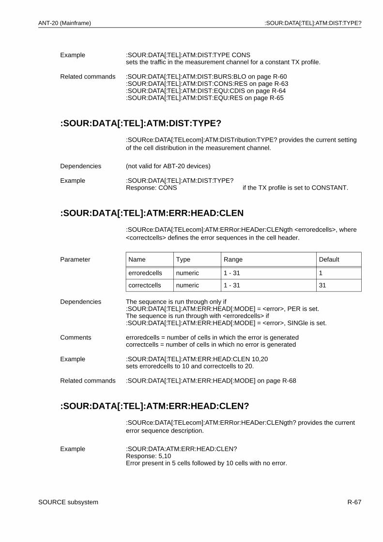
ANT-20 (Mainframe) :SOUR:DATA[:TEL]:ATM:DIST:TYPE?
:SOUR:DATA[:TEL]:ATM:DIST:TYPE?
:SOURce:DATA[:TELecom]:ATM:DISTribution:TYPE? provides the current setting of the cell distribution in the measurement channel.
:SOUR:DATA[:TEL]:ATM:ERR:HEAD:CLEN
:SOURce:DATA[:TELecom]:ATM:ERRor:HEADer:CLENgth <erroredcells>, where <correctcells> defines the error sequences in the cell header.
:SOUR:DATA[:TEL]:ATM:ERR:HEAD:CLEN?
:SOURce:DATA[:TELecom]:ATM:ERRor:HEADer:CLENgth? provides the current error sequence description.
Example :SOUR:DATA[:TEL]:ATM:DIST:TYPE CONS sets the traffic in the measurement channel for a constant TX profile.
Related commands :SOUR:DATA[:TEL]:ATM:DIST:BURS:BLO on page R-60:SOUR:DATA[:TEL]:ATM:DIST:CONS:RES on page R-63:SOUR:DATA[:TEL]:ATM:DIST:EQU:CDIS on page R-64:SOUR:DATA[:TEL]:ATM:DIST:EQU:RES on page R-65
Dependencies (not valid for ABT-20 devices)
Example :SOUR:DATA[:TEL]:ATM:DIST:TYPE?Response: CONS if the TX profile is set to CONSTANT.
Parameter Name Type Range Default
erroredcells numeric 1 - 31 1
correctcells numeric 1 - 31 31
Dependencies The sequence is run through only if :SOUR:DATA[:TEL]:ATM:ERR:HEAD[:MODE] = <error>, PER is set.The sequence is run through with <erroredcells> if :SOUR:DATA[:TEL]:ATM:ERR:HEAD[:MODE] = <error>, SINGle is set.
Comments erroredcells = number of cells in which the error is generatedcorrectcells = number of cells in which no error is generated
Example :SOUR:DATA[:TEL]:ATM:ERR:HEAD:CLEN 10,20 sets erroredcells to 10 and correctcells to 20.
Related commands :SOUR:DATA[:TEL]:ATM:ERR:HEAD[:MODE] on page R-68
Example :SOUR:DATA:ATM:ERR:HEAD:CLEN?Response: 5,10Error present in 5 cells followed by 10 cells with no error.
SOURCE subsystem R-67
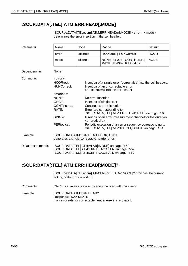
:SOUR:DATA[:TEL]:ATM:ERR:HEAD[:MODE] ANT-20 (Mainframe)
:SOUR:DATA[:TEL]:ATM:ERR:HEAD[:MODE]
:SOURce:DATA[:TELecom]:ATM:ERR:HEADer[:MODE] <error>, <mode> determines the error insertion in the cell header.
:SOUR:DATA[:TEL]:ATM:ERR:HEAD[:MODE]?
:SOURce:DATA[:TELecom]:ATM:ERRor:HEADer:MODE]? provides the current setting of the error insertion.
Parameter Name Type Range Default
error discrete HCORrect | HUNCorrect HCOR
mode discrete NONE | ONCE | CONTinuous | RATE | SINGle | PERiodical
NONE
Dependencies None
Comments <error> =HCORrect: Insertion of a single error (correctable) into the cell header..HUNCorrect. Insertion of an uncorrectable error
(≥ 2 bit errors) into the cell header<mode> =NONE: No error insertion..ONCE: Insertion of single errorCONTinuous: Continuous error insertionRATE: Error rate corresponding to
:SOUR:DATA[:TEL]:ATM:ERR:HEAD:RATE on page R-69SINGle: Insertion of an error measurement channel for the duration
<erroredcells>PERiodical: Periodic execution of an error sequence corresponding to
:SOUR:DATA[:TEL]:ATM:DIST:EQU:CDIS on page R-64
Example :SOUR:DATA:ATM:ERR:HEAD HCOR, ONCE generates a single correctable header error.
Related commands :SOUR:DATA[:TEL]:ATM:ALAR[:MODE] on page R-59:SOUR:DATA[:TEL]:ATM:ERR:HEAD:CLEN on page R-67:SOUR:DATA[:TEL]:ATM:ERR:HEAD:RATE on page R-69
Comments ONCE is a volatile state and cannot be read with this query.
Example :SOUR:DATA:ATM:ERR:HEAD?Response: HCOR,RATEif an error rate for correctable header errors is activated.
R-68 SOURCE subsystem
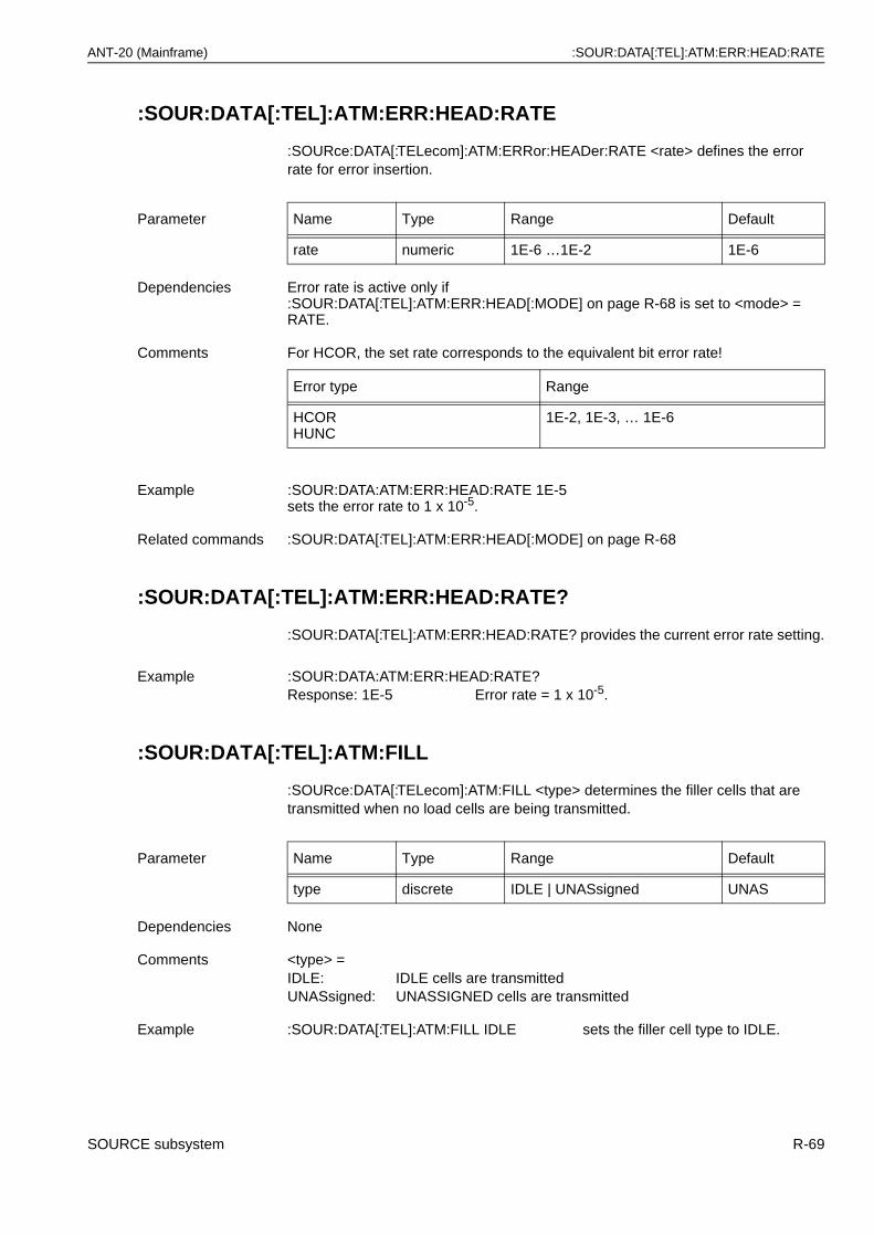
ANT-20 (Mainframe) :SOUR:DATA[:TEL]:ATM:ERR:HEAD:RATE
:SOUR:DATA[:TEL]:ATM:ERR:HEAD:RATE
:SOURce:DATA[:TELecom]:ATM:ERRor:HEADer:RATE <rate> defines the error rate for error insertion.
:SOUR:DATA[:TEL]:ATM:ERR:HEAD:RATE?
:SOUR:DATA[:TEL]:ATM:ERR:HEAD:RATE? provides the current error rate setting.
:SOUR:DATA[:TEL]:ATM:FILL
:SOURce:DATA[:TELecom]:ATM:FILL <type> determines the filler cells that are transmitted when no load cells are being transmitted.
Parameter Name Type Range Default
rate numeric 1E-6 …1E-2 1E-6
Dependencies Error rate is active only if :SOUR:DATA[:TEL]:ATM:ERR:HEAD[:MODE] on page R-68 is set to <mode> = RATE.
Comments For HCOR, the set rate corresponds to the equivalent bit error rate!
Error type Range
HCORHUNC
1E-2, 1E-3, … 1E-6
Example :SOUR:DATA:ATM:ERR:HEAD:RATE 1E-5 sets the error rate to 1 x 10⁻⁵.
Related commands :SOUR:DATA[:TEL]:ATM:ERR:HEAD[:MODE] on page R-68
Example :SOUR:DATA:ATM:ERR:HEAD:RATE?Response: 1E-5 Error rate = 1 x 10⁻⁵.
Parameter Name Type Range Default
type discrete IDLE | UNASsigned UNAS
Dependencies None
Comments <type> = IDLE: IDLE cells are transmittedUNASsigned: UNASSIGNED cells are transmitted
Example :SOUR:DATA[:TEL]:ATM:FILL IDLE sets the filler cell type to IDLE.
SOURCE subsystem R-69
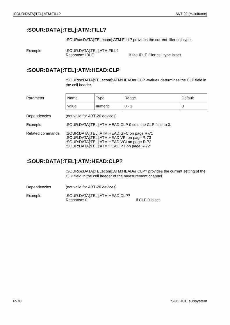
:SOUR:DATA[:TEL]:ATM:FILL? ANT-20 (Mainframe)
:SOUR:DATA[:TEL]:ATM:FILL?
:SOURce:DATA[:TELecom]:ATM:FILL? provides the current filler cell type.
:SOUR:DATA[:TEL]:ATM:HEAD:CLP
:SOURce:DATA[:TELecom]:ATM:HEADer:CLP <value> determines the CLP field in the cell header.
:SOUR:DATA[:TEL]:ATM:HEAD:CLP?
:SOURce:DATA[:TELecom]:ATM:HEADer:CLP? provides the current setting of the CLP field in the cell header of the measurement channel.
Example :SOUR:DATA[:TEL]:ATM:FILL?Response: IDLE if the IDLE filler cell type is set.
Parameter Name Type Range Default
value numeric 0 - 1 0
Dependencies (not valid for ABT-20 devices)
Example :SOUR:DATA[:TEL]:ATM:HEAD:CLP 0 sets the CLP field to 0.
Related commands :SOUR:DATA[:TEL]:ATM:HEAD:GFC on page R-71:SOUR:DATA[:TEL]:ATM:HEAD:VPI on page R-73:SOUR:DATA[:TEL]:ATM:HEAD:VCI on page R-72:SOUR:DATA[:TEL]:ATM:HEAD:PT on page R-72
Dependencies (not valid for ABT-20 devices)
Example :SOUR:DATA[:TEL]:ATM:HEAD:CLP?Response: 0 if CLP 0 is set.
R-70 SOURCE subsystem
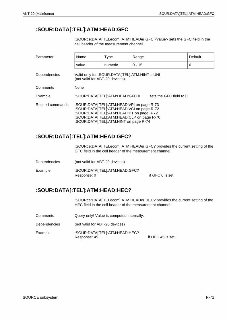
ANT-20 (Mainframe) :SOUR:DATA[:TEL]:ATM:HEAD:GFC
:SOUR:DATA[:TEL]:ATM:HEAD:GFC
:SOURce:DATA[:TELecom]:ATM:HEADer:GFC <value> sets the GFC field in the cell header of the measurement channel.
:SOUR:DATA[:TEL]:ATM:HEAD:GFC?
:SOURce:DATA[:TELecom]:ATM:HEADer:GFC? provides the current setting of the GFC field in the cell header of the measurement channel.
:SOUR:DATA[:TEL]:ATM:HEAD:HEC?
:SOURce:DATA[:TELecom]:ATM:HEADer:HEC? provides the current setting of the HEC field in the cell header of the measurement channel.
Parameter Name Type Range Default
value numeric 0 - 15 0
Dependencies Valid only for :SOUR:DATA[:TEL]:ATM:NINT = UNI (not valid for ABT-20 devices).
Comments None
Example :SOUR:DATA[:TEL]:ATM:HEAD:GFC 0 sets the GFC field to 0.
Related commands :SOUR:DATA[:TEL]:ATM:HEAD:VPI on page R-73:SOUR:DATA[:TEL]:ATM:HEAD:VCI on page R-72:SOUR:DATA[:TEL]:ATM:HEAD:PT on page R-72:SOUR:DATA[:TEL]:ATM:HEAD:CLP on page R-70:SOUR:DATA[:TEL]:ATM:NINT on page R-74
Dependencies (not valid for ABT-20 devices)
Example :SOUR:DATA[:TEL]:ATM:HEAD:GFC?Response: 0 if GFC 0 is set.
Comments Query only! Value is computed internally.
Dependencies (not valid for ABT-20 devices)
Example :SOUR:DATA[:TEL]:ATM:HEAD:HEC?Response: 45 if HEC 45 is set.
SOURCE subsystem R-71
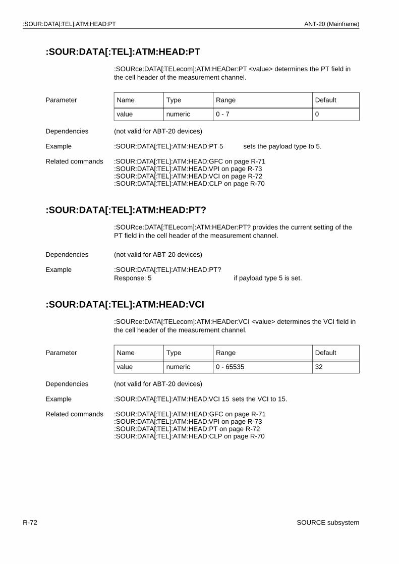
:SOUR:DATA[:TEL]:ATM:HEAD:PT ANT-20 (Mainframe)
:SOUR:DATA[:TEL]:ATM:HEAD:PT
:SOURce:DATA[:TELecom]:ATM:HEADer:PT <value> determines the PT field in the cell header of the measurement channel.
:SOUR:DATA[:TEL]:ATM:HEAD:PT?
:SOURce:DATA[:TELecom]:ATM:HEADer:PT? provides the current setting of the PT field in the cell header of the measurement channel.
:SOUR:DATA[:TEL]:ATM:HEAD:VCI
:SOURce:DATA[:TELecom]:ATM:HEADer:VCI <value> determines the VCI field in the cell header of the measurement channel.
Parameter Name Type Range Default
value numeric 0 - 7 0
Dependencies (not valid for ABT-20 devices)
Example :SOUR:DATA[:TEL]:ATM:HEAD:PT 5 sets the payload type to 5.
Related commands :SOUR:DATA[:TEL]:ATM:HEAD:GFC on page R-71:SOUR:DATA[:TEL]:ATM:HEAD:VPI on page R-73:SOUR:DATA[:TEL]:ATM:HEAD:VCI on page R-72:SOUR:DATA[:TEL]:ATM:HEAD:CLP on page R-70
Dependencies (not valid for ABT-20 devices)
Example :SOUR:DATA[:TEL]:ATM:HEAD:PT?Response: 5 if payload type 5 is set.
Parameter Name Type Range Default
value numeric 0 - 65535 32
Dependencies (not valid for ABT-20 devices)
Example :SOUR:DATA[:TEL]:ATM:HEAD:VCI 15 sets the VCI to 15.
Related commands :SOUR:DATA[:TEL]:ATM:HEAD:GFC on page R-71:SOUR:DATA[:TEL]:ATM:HEAD:VPI on page R-73:SOUR:DATA[:TEL]:ATM:HEAD:PT on page R-72:SOUR:DATA[:TEL]:ATM:HEAD:CLP on page R-70
R-72 SOURCE subsystem
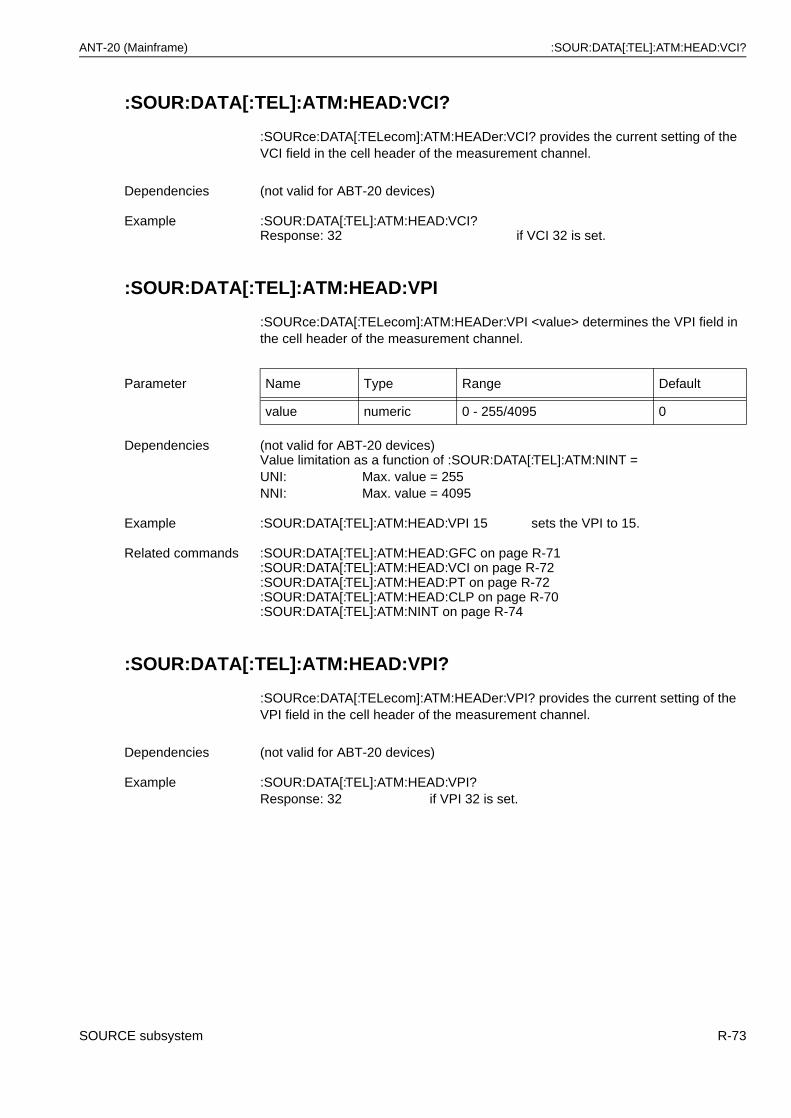
ANT-20 (Mainframe) :SOUR:DATA[:TEL]:ATM:HEAD:VCI?
:SOUR:DATA[:TEL]:ATM:HEAD:VCI?
:SOURce:DATA[:TELecom]:ATM:HEADer:VCI? provides the current setting of the VCI field in the cell header of the measurement channel.
:SOUR:DATA[:TEL]:ATM:HEAD:VPI
:SOURce:DATA[:TELecom]:ATM:HEADer:VPI <value> determines the VPI field in the cell header of the measurement channel.
:SOUR:DATA[:TEL]:ATM:HEAD:VPI?
:SOURce:DATA[:TELecom]:ATM:HEADer:VPI? provides the current setting of the VPI field in the cell header of the measurement channel.
Dependencies (not valid for ABT-20 devices)
Example :SOUR:DATA[:TEL]:ATM:HEAD:VCI?Response: 32 if VCI 32 is set.
Parameter Name Type Range Default
value numeric 0 - 255/4095 0
Dependencies (not valid for ABT-20 devices)Value limitation as a function of :SOUR:DATA[:TEL]:ATM:NINT =UNI: Max. value = 255NNI: Max. value = 4095
Example :SOUR:DATA[:TEL]:ATM:HEAD:VPI 15 sets the VPI to 15.
Related commands :SOUR:DATA[:TEL]:ATM:HEAD:GFC on page R-71:SOUR:DATA[:TEL]:ATM:HEAD:VCI on page R-72:SOUR:DATA[:TEL]:ATM:HEAD:PT on page R-72:SOUR:DATA[:TEL]:ATM:HEAD:CLP on page R-70:SOUR:DATA[:TEL]:ATM:NINT on page R-74
Dependencies (not valid for ABT-20 devices)
Example :SOUR:DATA[:TEL]:ATM:HEAD:VPI?Response: 32 if VPI 32 is set.
SOURCE subsystem R-73
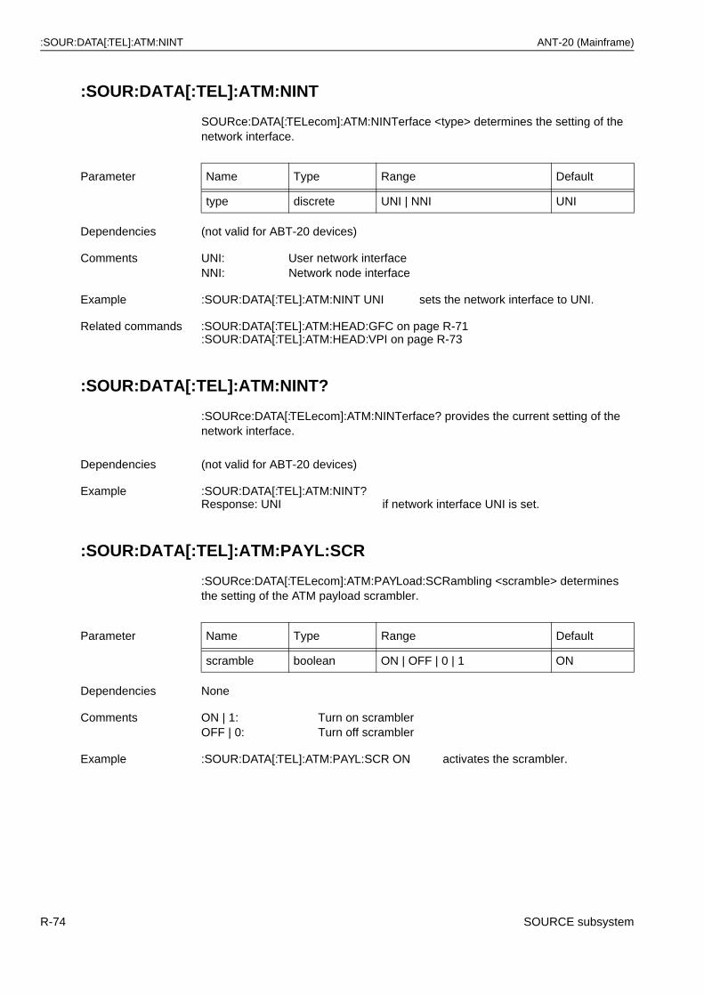
:SOUR:DATA[:TEL]:ATM:NINT ANT-20 (Mainframe)
:SOUR:DATA[:TEL]:ATM:NINT
SOURce:DATA[:TELecom]:ATM:NINTerface <type> determines the setting of the network interface.
:SOUR:DATA[:TEL]:ATM:NINT?
:SOURce:DATA[:TELecom]:ATM:NINTerface? provides the current setting of the network interface.
:SOUR:DATA[:TEL]:ATM:PAYL:SCR
:SOURce:DATA[:TELecom]:ATM:PAYLoad:SCRambling <scramble> determines the setting of the ATM payload scrambler.
Parameter Name Type Range Default
type discrete UNI | NNI UNI
Dependencies (not valid for ABT-20 devices)
Comments UNI: User network interfaceNNI: Network node interface
Example :SOUR:DATA[:TEL]:ATM:NINT UNI sets the network interface to UNI.
Related commands :SOUR:DATA[:TEL]:ATM:HEAD:GFC on page R-71:SOUR:DATA[:TEL]:ATM:HEAD:VPI on page R-73
Dependencies (not valid for ABT-20 devices)
Example :SOUR:DATA[:TEL]:ATM:NINT?Response: UNI if network interface UNI is set.
Parameter Name Type Range Default
scramble boolean ON | OFF | 0 | 1 ON
Dependencies None
Comments ON | 1: Turn on scramblerOFF | 0: Turn off scrambler
Example :SOUR:DATA[:TEL]:ATM:PAYL:SCR ON activates the scrambler.
R-74 SOURCE subsystem
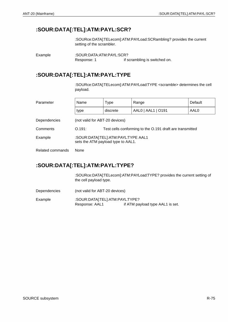
ANT-20 (Mainframe) :SOUR:DATA[:TEL]:ATM:PAYL:SCR?
:SOUR:DATA[:TEL]:ATM:PAYL:SCR?
:SOURce:DATA[:TELecom]:ATM:PAYLoad:SCRambling? provides the current setting of the scrambler.
:SOUR:DATA[:TEL]:ATM:PAYL:TYPE
:SOURce:DATA[:TELecom]:ATM:PAYLoad:TYPE <scramble> determines the cell payload.
:SOUR:DATA[:TEL]:ATM:PAYL:TYPE?
:SOURce:DATA[:TELecom]:ATM:PAYLoad:TYPE? provides the current setting of the cell payload type.
Example :SOUR:DATA:ATM:PAYL:SCR?Response: 1 if scrambling is switched on.
Parameter Name Type Range Default
type discrete AAL0 | AAL1 | O191 AAL0
Dependencies (not valid for ABT-20 devices)
Comments O.191: Test cells conforming to the O.191 draft are transmitted
Example :SOUR:DATA[:TEL]:ATM:PAYL:TYPE AAL1 sets the ATM payload type to AAL1.
Related commands None
Dependencies (not valid for ABT-20 devices)
Example :SOUR:DATA[:TEL]:ATM:PAYL:TYPE?Response: AAL1 if ATM payload type AAL1 is set.
SOURCE subsystem R-75
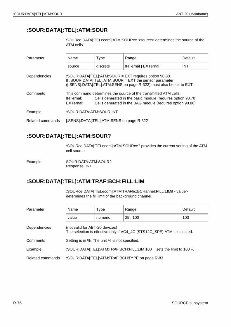
:SOUR:DATA[:TEL]:ATM:SOUR ANT-20 (Mainframe)
:SOUR:DATA[:TEL]:ATM:SOUR
SOURce:DATA[:TELecom]:ATM:SOURce <source> determines the source of the ATM cells.
:SOUR:DATA[:TEL]:ATM:SOUR?
:SOURce:DATA[:TELecom]:ATM:SOURce? provides the current setting of the ATM cell source.
:SOUR:DATA[:TEL]:ATM:TRAF:BCH:FILL:LIM
:SOURce:DATA[:TELecom]:ATM:TRAFfic:BCHannel:FILL:LIMit <value> determines the fill limit of the background channel.
Parameter Name Type Range Default
source discrete INTernal | EXTernal INT
Dependencies :SOUR:DATA[:TEL]:ATM:SOUR = EXT requires option 90.80.If :SOUR:DATA[:TEL]:ATM:SOUR = EXT the sensor parameter ([:SENS]:DATA[:TEL]:ATM:SENS on page R-322) must also be set to EXT.
Comments This command determines the source of the transmitted ATM cells:INTernal: Cells generated in the basic module (requires option 90.70)EXTernal: Cells generated in the BAG module (requires option 90.80)
Example :SOUR:DATA:ATM:SOUR INT
Related commands [:SENS]:DATA[:TEL]:ATM:SENS on page R-322
Example SOUR:DATA:ATM:SOUR?Response: INT
Parameter Name Type Range Default
value numeric 25 | 100 100
Dependencies (not valid for ABT-20 devices)The selection is effective only if VC4_4C (STS12C_SPE) ATM is selected.
Comments Setting is in %. The unit % is not specified.
Example :SOUR:DATA[:TEL]:ATM:TRAF:BCH:FILL:LIM 100 sets the limit to 100 %
Related commands :SOUR:DATA[:TEL]:ATM:TRAF:BCH:TYPE on page R-83
R-76 SOURCE subsystem
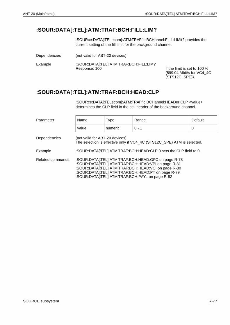
ANT-20 (Mainframe) :SOUR:DATA[:TEL]:ATM:TRAF:BCH:FILL:LIM?
:SOUR:DATA[:TEL]:ATM:TRAF:BCH:FILL:LIM?
:SOURce:DATA[:TELecom]:ATM:TRAFfic:BCHannel:FILL:LIMit? provides the current setting of the fill limit for the background channel.
:SOUR:DATA[:TEL]:ATM:TRAF:BCH:HEAD:CLP
:SOURce:DATA[:TELecom]:ATM:TRAFfic:BCHannel:HEADer:CLP <value> determines the CLP field in the cell header of the background channel.
Dependencies (not valid for ABT-20 devices)
Example :SOUR:DATA[:TEL]:ATM:TRAF:BCH:FILL:LIM?Response: 100 if the limit is set to 100 %
(599.04 Mbit/s for VC4_4C (STS12C_SPE)).
Parameter Name Type Range Default
value numeric 0 - 1 0
Dependencies (not valid for ABT-20 devices)The selection is effective only if VC4_4C (STS12C_SPE) ATM is selected.
Example :SOUR:DATA[:TEL]:ATM:TRAF:BCH:HEAD:CLP 0 sets the CLP field to 0.
Related commands :SOUR:DATA[:TEL]:ATM:TRAF:BCH:HEAD:GFC on page R-78:SOUR:DATA[:TEL]:ATM:TRAF:BCH:HEAD:VPI on page R-81:SOUR:DATA[:TEL]:ATM:TRAF:BCH:HEAD:VCI on page R-80:SOUR:DATA[:TEL]:ATM:TRAF:BCH:HEAD:PT on page R-79:SOUR:DATA[:TEL]:ATM:TRAF:BCH:PAYL on page R-82
SOURCE subsystem R-77
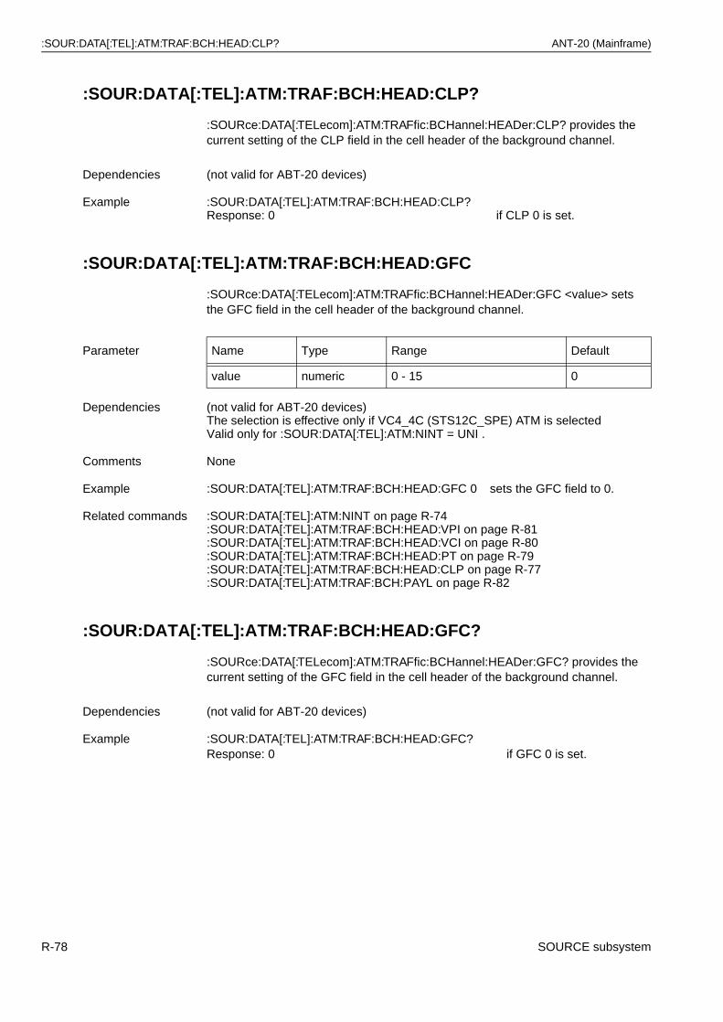
:SOUR:DATA[:TEL]:ATM:TRAF:BCH:HEAD:CLP? ANT-20 (Mainframe)
:SOUR:DATA[:TEL]:ATM:TRAF:BCH:HEAD:CLP?
:SOURce:DATA[:TELecom]:ATM:TRAFfic:BCHannel:HEADer:CLP? provides the current setting of the CLP field in the cell header of the background channel.
:SOUR:DATA[:TEL]:ATM:TRAF:BCH:HEAD:GFC
:SOURce:DATA[:TELecom]:ATM:TRAFfic:BCHannel:HEADer:GFC <value> sets the GFC field in the cell header of the background channel.
:SOUR:DATA[:TEL]:ATM:TRAF:BCH:HEAD:GFC?
:SOURce:DATA[:TELecom]:ATM:TRAFfic:BCHannel:HEADer:GFC? provides the current setting of the GFC field in the cell header of the background channel.
Dependencies (not valid for ABT-20 devices)
Example :SOUR:DATA[:TEL]:ATM:TRAF:BCH:HEAD:CLP?Response: 0 if CLP 0 is set.
Parameter Name Type Range Default
value numeric 0 - 15 0
Dependencies (not valid for ABT-20 devices)The selection is effective only if VC4_4C (STS12C_SPE) ATM is selectedValid only for :SOUR:DATA[:TEL]:ATM:NINT = UNI .
Comments None
Example :SOUR:DATA[:TEL]:ATM:TRAF:BCH:HEAD:GFC 0 sets the GFC field to 0.
Related commands :SOUR:DATA[:TEL]:ATM:NINT on page R-74:SOUR:DATA[:TEL]:ATM:TRAF:BCH:HEAD:VPI on page R-81:SOUR:DATA[:TEL]:ATM:TRAF:BCH:HEAD:VCI on page R-80:SOUR:DATA[:TEL]:ATM:TRAF:BCH:HEAD:PT on page R-79:SOUR:DATA[:TEL]:ATM:TRAF:BCH:HEAD:CLP on page R-77:SOUR:DATA[:TEL]:ATM:TRAF:BCH:PAYL on page R-82
Dependencies (not valid for ABT-20 devices)
Example :SOUR:DATA[:TEL]:ATM:TRAF:BCH:HEAD:GFC?Response: 0 if GFC 0 is set.
R-78 SOURCE subsystem
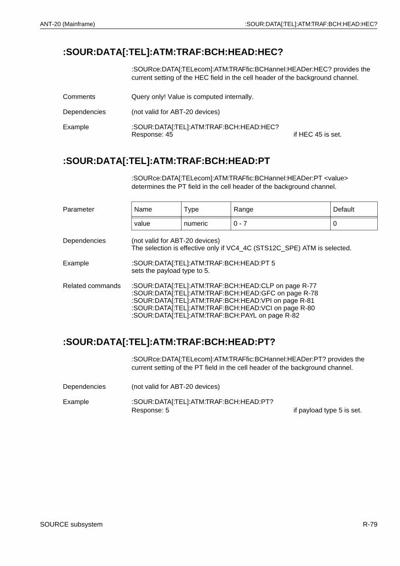
ANT-20 (Mainframe) :SOUR:DATA[:TEL]:ATM:TRAF:BCH:HEAD:HEC?
:SOUR:DATA[:TEL]:ATM:TRAF:BCH:HEAD:HEC?
:SOURce:DATA[:TELecom]:ATM:TRAFfic:BCHannel:HEADer:HEC? provides the current setting of the HEC field in the cell header of the background channel.
:SOUR:DATA[:TEL]:ATM:TRAF:BCH:HEAD:PT
:SOURce:DATA[:TELecom]:ATM:TRAFfic:BCHannel:HEADer:PT <value> determines the PT field in the cell header of the background channel.
:SOUR:DATA[:TEL]:ATM:TRAF:BCH:HEAD:PT?
:SOURce:DATA[:TELecom]:ATM:TRAFfic:BCHannel:HEADer:PT? provides the current setting of the PT field in the cell header of the background channel.
Comments Query only! Value is computed internally.
Dependencies (not valid for ABT-20 devices)
Example :SOUR:DATA[:TEL]:ATM:TRAF:BCH:HEAD:HEC?Response: 45 if HEC 45 is set.
Parameter Name Type Range Default
value numeric 0 - 7 0
Dependencies (not valid for ABT-20 devices)The selection is effective only if VC4_4C (STS12C_SPE) ATM is selected.
Example :SOUR:DATA[:TEL]:ATM:TRAF:BCH:HEAD:PT 5sets the payload type to 5.
Related commands :SOUR:DATA[:TEL]:ATM:TRAF:BCH:HEAD:CLP on page R-77:SOUR:DATA[:TEL]:ATM:TRAF:BCH:HEAD:GFC on page R-78:SOUR:DATA[:TEL]:ATM:TRAF:BCH:HEAD:VPI on page R-81:SOUR:DATA[:TEL]:ATM:TRAF:BCH:HEAD:VCI on page R-80:SOUR:DATA[:TEL]:ATM:TRAF:BCH:PAYL on page R-82
Dependencies (not valid for ABT-20 devices)
Example :SOUR:DATA[:TEL]:ATM:TRAF:BCH:HEAD:PT?Response: 5 if payload type 5 is set.
SOURCE subsystem R-79
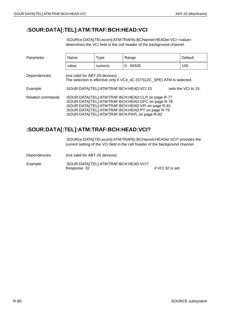
:SOUR:DATA[:TEL]:ATM:TRAF:BCH:HEAD:VCI ANT-20 (Mainframe)
:SOUR:DATA[:TEL]:ATM:TRAF:BCH:HEAD:VCI
:SOURce:DATA[:TELecom]:ATM:TRAFfic:BCHannel:HEADer:VCI <value> determines the VCI field in the cell header of the background channel.
:SOUR:DATA[:TEL]:ATM:TRAF:BCH:HEAD:VCI?
:SOURce:DATA[:TELecom]:ATM:TRAFfic:BCHannel:HEADer:VCI? provides the current setting of the VCI field in the cell header of the background channel.
Parameter Name Type Range Default
value numeric 0 - 65535 100
Dependencies (not valid for ABT-20 devices)The selection is effective only if VC4_4C (STS12C_SPE) ATM is selected.
Example :SOUR:DATA[:TEL]:ATM:TRAF:BCH:HEAD:VCI 15 sets the VCI to 15.
Related commands :SOUR:DATA[:TEL]:ATM:TRAF:BCH:HEAD:CLP on page R-77:SOUR:DATA[:TEL]:ATM:TRAF:BCH:HEAD:GFC on page R-78:SOUR:DATA[:TEL]:ATM:TRAF:BCH:HEAD:VPI on page R-81:SOUR:DATA[:TEL]:ATM:TRAF:BCH:HEAD:PT on page R-79:SOUR:DATA[:TEL]:ATM:TRAF:BCH:PAYL on page R-82
Dependencies (not valid for ABT-20 devices)
Example :SOUR:DATA[:TEL]:ATM:TRAF:BCH:HEAD:VCI?Response: 32 if VCI 32 is set.
R-80 SOURCE subsystem
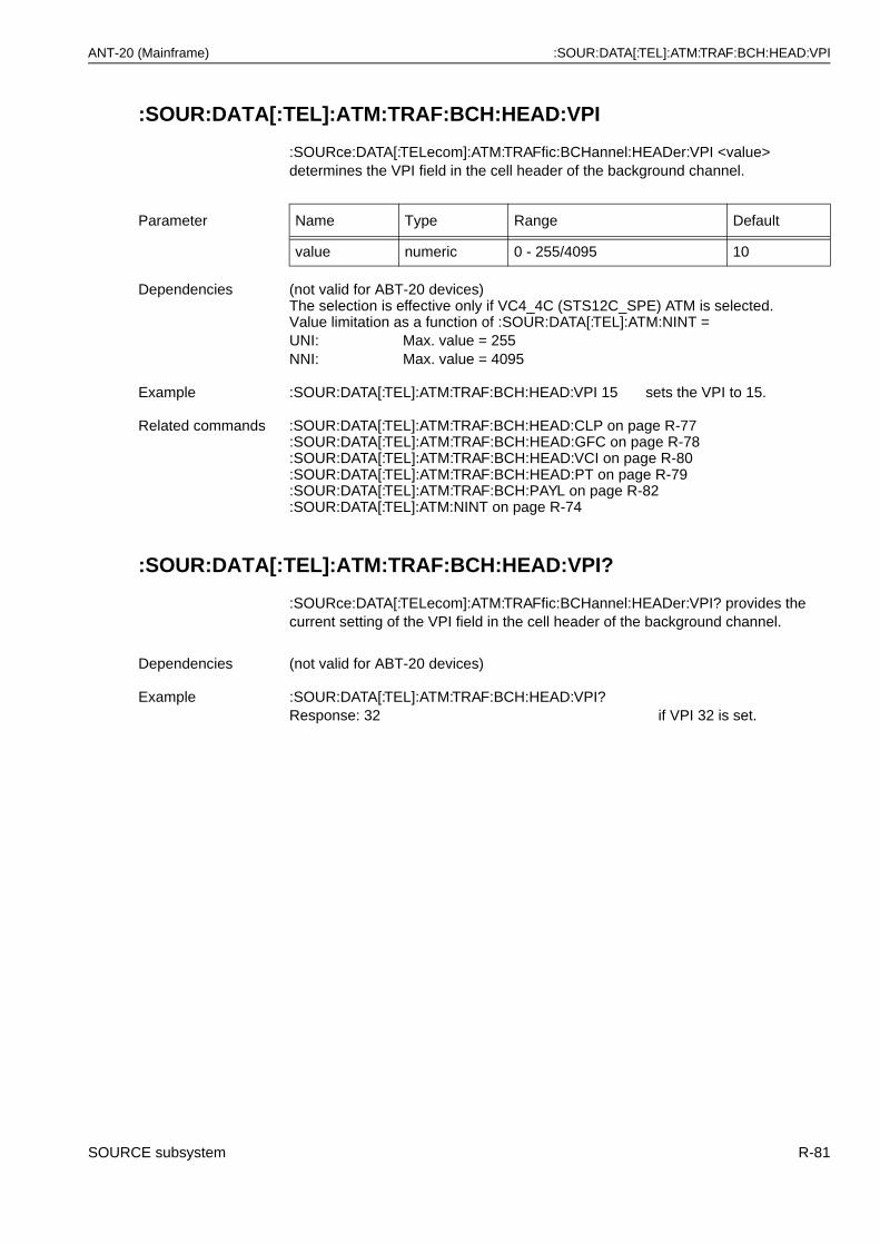
ANT-20 (Mainframe) :SOUR:DATA[:TEL]:ATM:TRAF:BCH:HEAD:VPI
:SOUR:DATA[:TEL]:ATM:TRAF:BCH:HEAD:VPI
:SOURce:DATA[:TELecom]:ATM:TRAFfic:BCHannel:HEADer:VPI <value> determines the VPI field in the cell header of the background channel.
:SOUR:DATA[:TEL]:ATM:TRAF:BCH:HEAD:VPI?
:SOURce:DATA[:TELecom]:ATM:TRAFfic:BCHannel:HEADer:VPI? provides the current setting of the VPI field in the cell header of the background channel.
Parameter Name Type Range Default
value numeric 0 - 255/4095 10
Dependencies (not valid for ABT-20 devices)The selection is effective only if VC4_4C (STS12C_SPE) ATM is selected.Value limitation as a function of :SOUR:DATA[:TEL]:ATM:NINT =UNI: Max. value = 255NNI: Max. value = 4095
Example :SOUR:DATA[:TEL]:ATM:TRAF:BCH:HEAD:VPI 15 sets the VPI to 15.
Related commands :SOUR:DATA[:TEL]:ATM:TRAF:BCH:HEAD:CLP on page R-77:SOUR:DATA[:TEL]:ATM:TRAF:BCH:HEAD:GFC on page R-78:SOUR:DATA[:TEL]:ATM:TRAF:BCH:HEAD:VCI on page R-80:SOUR:DATA[:TEL]:ATM:TRAF:BCH:HEAD:PT on page R-79:SOUR:DATA[:TEL]:ATM:TRAF:BCH:PAYL on page R-82:SOUR:DATA[:TEL]:ATM:NINT on page R-74
Dependencies (not valid for ABT-20 devices)
Example :SOUR:DATA[:TEL]:ATM:TRAF:BCH:HEAD:VPI?Response: 32 if VPI 32 is set.
SOURCE subsystem R-81
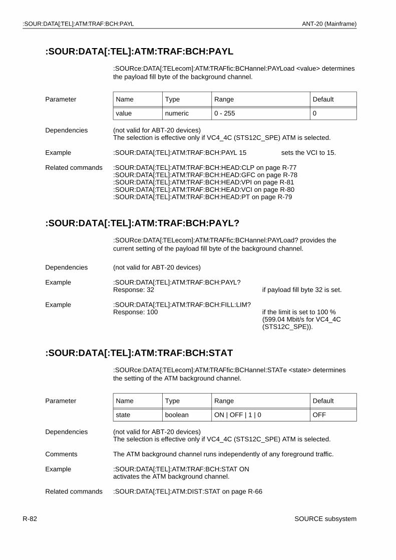
:SOUR:DATA[:TEL]:ATM:TRAF:BCH:PAYL ANT-20 (Mainframe)
:SOUR:DATA[:TEL]:ATM:TRAF:BCH:PAYL
:SOURce:DATA[:TELecom]:ATM:TRAFfic:BCHannel:PAYLoad <value> determines the payload fill byte of the background channel.
:SOUR:DATA[:TEL]:ATM:TRAF:BCH:PAYL?
:SOURce:DATA[:TELecom]:ATM:TRAFfic:BCHannel:PAYLoad? provides the current setting of the payload fill byte of the background channel.
:SOUR:DATA[:TEL]:ATM:TRAF:BCH:STAT
:SOURce:DATA[:TELecom]:ATM:TRAFfic:BCHannel:STATe <state> determines the setting of the ATM background channel.
Parameter Name Type Range Default
value numeric 0 - 255 0
Dependencies (not valid for ABT-20 devices)The selection is effective only if VC4_4C (STS12C_SPE) ATM is selected.
Example :SOUR:DATA[:TEL]:ATM:TRAF:BCH:PAYL 15 sets the VCI to 15.
Related commands :SOUR:DATA[:TEL]:ATM:TRAF:BCH:HEAD:CLP on page R-77:SOUR:DATA[:TEL]:ATM:TRAF:BCH:HEAD:GFC on page R-78:SOUR:DATA[:TEL]:ATM:TRAF:BCH:HEAD:VPI on page R-81:SOUR:DATA[:TEL]:ATM:TRAF:BCH:HEAD:VCI on page R-80:SOUR:DATA[:TEL]:ATM:TRAF:BCH:HEAD:PT on page R-79
Dependencies (not valid for ABT-20 devices)
Example :SOUR:DATA[:TEL]:ATM:TRAF:BCH:PAYL?Response: 32 if payload fill byte 32 is set.
Example :SOUR:DATA[:TEL]:ATM:TRAF:BCH:FILL:LIM?Response: 100 if the limit is set to 100 %
(599.04 Mbit/s for VC4_4C (STS12C_SPE)).
Parameter Name Type Range Default
state boolean ON | OFF | 1 | 0 OFF
Dependencies (not valid for ABT-20 devices)The selection is effective only if VC4_4C (STS12C_SPE) ATM is selected.
Comments The ATM background channel runs independently of any foreground traffic.
Example :SOUR:DATA[:TEL]:ATM:TRAF:BCH:STAT ONactivates the ATM background channel.
Related commands :SOUR:DATA[:TEL]:ATM:DIST:STAT on page R-66
R-82 SOURCE subsystem
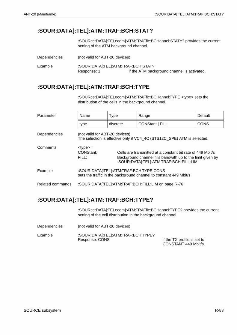
ANT-20 (Mainframe) :SOUR:DATA[:TEL]:ATM:TRAF:BCH:STAT?
:SOUR:DATA[:TEL]:ATM:TRAF:BCH:STAT?
:SOURce:DATA[:TELecom]:ATM:TRAFfic:BCHannel:STATe? provides the current setting of the ATM background channel.
:SOUR:DATA[:TEL]:ATM:TRAF:BCH:TYPE
:SOURce:DATA[:TELecom]:ATM:TRAFfic:BCHannel:TYPE <type> sets the distribution of the cells in the background channel.
:SOUR:DATA[:TEL]:ATM:TRAF:BCH:TYPE?
:SOURce:DATA[:TELecom]:ATM:TRAFfic:BCHannel:TYPE? provides the current setting of the cell distribution in the background channel.
Dependencies (not valid for ABT-20 devices)
Example :SOUR:DATA[:TEL]:ATM:TRAF:BCH:STAT?Response: 1 if the ATM background channel is activated.
Parameter Name Type Range Default
type discrete CONStant | FILL CONS
Dependencies (not valid for ABT-20 devices)The selection is effective only if VC4_4C (STS12C_SPE) ATM is selected.
Comments <type> =CONStant: Cells are transmitted at a constant bit rate of 449 Mbit/sFILL: Background channel fills bandwith up to the limit given by
:SOUR:DATA[:TEL]:ATM:TRAF:BCH:FILL:LIM
Example :SOUR:DATA[:TEL]:ATM:TRAF:BCH:TYPE CONS sets the traffic in the background channel to constant 449 Mbit/s
Related commands :SOUR:DATA[:TEL]:ATM:TRAF:BCH:FILL:LIM on page R-76
Dependencies (not valid for ABT-20 devices)
Example :SOUR:DATA[:TEL]:ATM:TRAF:BCH:TYPE?Response: CONS if the TX profile is set to
CONSTANT 449 Mbit/s.
SOURCE subsystem R-83
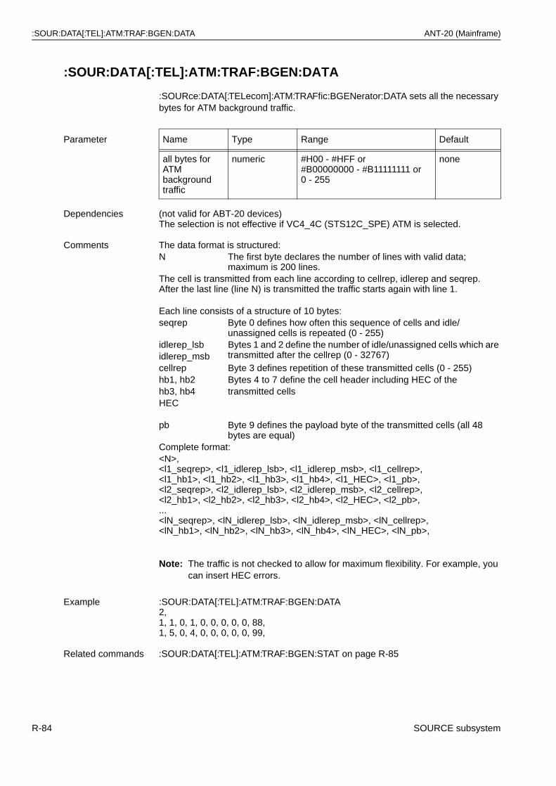
:SOUR:DATA[:TEL]:ATM:TRAF:BGEN:DATA ANT-20 (Mainframe)
:SOUR:DATA[:TEL]:ATM:TRAF:BGEN:DATA
:SOURce:DATA[:TELecom]:ATM:TRAFfic:BGENerator:DATA sets all the necessary bytes for ATM background traffic.
Note: The traffic is not checked to allow for maximum flexibility. For example, you can insert HEC errors.
Parameter Name Type Range Default
all bytes for ATM background traffic
numeric #H00 - #HFF or#B00000000 - #B11111111 or 0 - 255
none
Dependencies (not valid for ABT-20 devices)The selection is not effective if VC4_4C (STS12C_SPE) ATM is selected.
Comments The data format is structured:N The first byte declares the number of lines with valid data;
maximum is 200 lines.The cell is transmitted from each line according to cellrep, idlerep and seqrep.After the last line (line N) is transmitted the traffic starts again with line 1.
Each line consists of a structure of 10 bytes:seqrep Byte 0 defines how often this sequence of cells and idle/
unassigned cells is repeated (0 - 255)idlerep_lsb Bytes 1 and 2 define the number of idle/unassigned cells which are
transmitted after the cellrep (0 - 32767)idlerep_msbcellrep Byte 3 defines repetition of these transmitted cells (0 - 255)hb1, hb2 Bytes 4 to 7 define the cell header including HEC of thehb3, hb4 transmitted cellsHEC
pb Byte 9 defines the payload byte of the transmitted cells (all 48 bytes are equal)
Complete format:<N>,<l1_seqrep>, <l1_idlerep_lsb>, <l1_idlerep_msb>, <l1_cellrep>, <l1_hb1>, <l1_hb2>, <l1_hb3>, <l1_hb4>, <l1_HEC>, <l1_pb>, <l2_seqrep>, <l2_idlerep_lsb>, <l2_idlerep_msb>, <l2_cellrep>, <l2_hb1>, <l2_hb2>, <l2_hb3>, <l2_hb4>, <l2_HEC>, <l2_pb>, ...<lN_seqrep>, <lN_idlerep_lsb>, <lN_idlerep_msb>, <lN_cellrep>, <lN_hb1>, <lN_hb2>, <lN_hb3>, <lN_hb4>, <lN_HEC>, <lN_pb>,
Example :SOUR:DATA[:TEL]:ATM:TRAF:BGEN:DATA 2, 1, 1, 0, 1, 0, 0, 0, 0, 0, 88,1, 5, 0, 4, 0, 0, 0, 0, 0, 99,
Related commands :SOUR:DATA[:TEL]:ATM:TRAF:BGEN:STAT on page R-85
R-84 SOURCE subsystem
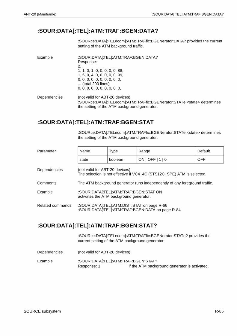
ANT-20 (Mainframe) :SOUR:DATA[:TEL]:ATM:TRAF:BGEN:DATA?
:SOUR:DATA[:TEL]:ATM:TRAF:BGEN:DATA?
:SOURce:DATA[:TELecom]:ATM:TRAFfic:BGENerator:DATA? provides the current setting of the ATM background traffic.
:SOUR:DATA[:TEL]:ATM:TRAF:BGEN:STAT
:SOURce:DATA[:TELecom]:ATM:TRAFfic:BGENerator:STATe <state> determines the setting of the ATM background generator.
:SOUR:DATA[:TEL]:ATM:TRAF:BGEN:STAT?
:SOURce:DATA[:TELecom]:ATM:TRAFfic:BGENerator:STATe? provides the current setting of the ATM background generator.
Example :SOUR:DATA[:TEL]:ATM:TRAF:BGEN:DATA?Response:2, 1, 1, 0, 1, 0, 0, 0, 0, 0, 88,1, 5, 0, 4, 0, 0, 0, 0, 0, 99,0, 0, 0, 0, 0, 0, 0, 0, 0, 0,... (total 200 lines)0, 0, 0, 0, 0, 0, 0, 0, 0, 0,
Dependencies (not valid for ABT-20 devices):SOURce:DATA[:TELecom]:ATM:TRAFfic:BGENerator:STATe <state> determines the setting of the ATM background generator.
Parameter Name Type Range Default
state boolean ON | OFF | 1 | 0 OFF
Dependencies (not valid for ABT-20 devices)The selection is not effective if VC4_4C (STS12C_SPE) ATM is selected.
Comments The ATM background generator runs independently of any foreground traffic.
Example :SOUR:DATA[:TEL]:ATM:TRAF:BGEN:STAT ONactivates the ATM background generator.
Related commands :SOUR:DATA[:TEL]:ATM:DIST:STAT on page R-66:SOUR:DATA[:TEL]:ATM:TRAF:BGEN:DATA on page R-84
Dependencies (not valid for ABT-20 devices)
Example :SOUR:DATA[:TEL]:ATM:TRAF:BGEN:STAT?Response: 1 if the ATM background generator is activated.
SOURCE subsystem R-85
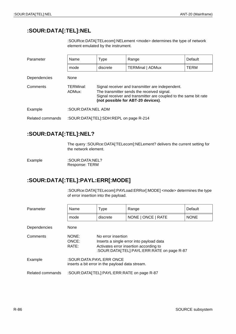
:SOUR:DATA[:TEL]:NEL ANT-20 (Mainframe)
:SOUR:DATA[:TEL]:NEL
:SOURce:DATA[:TELecom]:NELement <mode> determines the type of network element emulated by the instrument.
:SOUR:DATA[:TEL]:NEL?
The query :SOURce:DATA[:TELecom]:NELement? delivers the current setting for the network element.
:SOUR:DATA[:TEL]:PAYL:ERR[:MODE]
:SOURce:DATA[:TELecom]:PAYLoad:ERRor[:MODE] <mode> determines the type of error insertion into the payload.
Parameter Name Type Range Default
mode discrete TERMinal | ADMux TERM
Dependencies None
Comments TERMinal: Signal receiver and transmitter are independent.ADMux: The transmitter sends the received signal.
Signal receiver and transmitter are coupled to the same bit rate (not possible for ABT-20 devices).
Example :SOUR:DATA:NEL ADM
Related commands :SOUR:DATA[:TEL]:SDH:REPL on page R-214
Example :SOUR:DATA:NEL?Response: TERM
Parameter Name Type Range Default
mode discrete NONE | ONCE | RATE NONE
Dependencies None
Comments NONE: No error insertionONCE: Inserts a single error into payload dataRATE: Activates error insertion according to
:SOUR:DATA[:TEL]:PAYL:ERR:RATE on page R-87
Example :SOUR:DATA:PAYL:ERR ONCEinserts a bit error in the payload data stream.
Related commands :SOUR:DATA[:TEL]:PAYL:ERR:RATE on page R-87
R-86 SOURCE subsystem
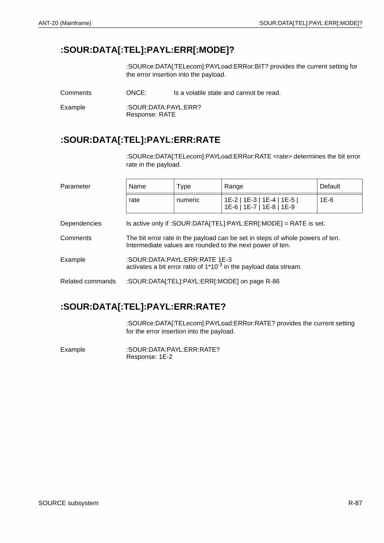
ANT-20 (Mainframe) :SOUR:DATA[:TEL]:PAYL:ERR[:MODE]?
:SOUR:DATA[:TEL]:PAYL:ERR[:MODE]?
:SOURce:DATA[:TELecom]:PAYLoad:ERRor:BIT? provides the current setting for the error insertion into the payload.
:SOUR:DATA[:TEL]:PAYL:ERR:RATE
:SOURce:DATA[:TELecom]:PAYLoad:ERRor:RATE <rate> determines the bit error rate in the payload.
:SOUR:DATA[:TEL]:PAYL:ERR:RATE?
:SOURce:DATA[:TELecom]:PAYLoad:ERRor:RATE? provides the current setting for the error insertion into the payload.
Comments ONCE: Is a volatile state and cannot be read.
Example :SOUR:DATA:PAYL:ERR?Response: RATE
Parameter Name Type Range Default
rate numeric 1E-2 | 1E-3 | 1E-4 | 1E-5 | 1E-6 | 1E-7 | 1E-8 | 1E-9
1E-6
Dependencies Is active only if :SOUR:DATA[:TEL]:PAYL:ERR[:MODE] = RATE is set.
Comments The bit error rate in the payload can be set in steps of whole powers of ten. Intermediate values are rounded to the next power of ten.
Example :SOUR:DATA:PAYL:ERR:RATE 1E-3activates a bit error ratio of 1*10-3 in the payload data stream.
Related commands :SOUR:DATA[:TEL]:PAYL:ERR[:MODE] on page R-86
Example :SOUR:DATA:PAYL:ERR:RATE?Response: 1E-2
SOURCE subsystem R-87
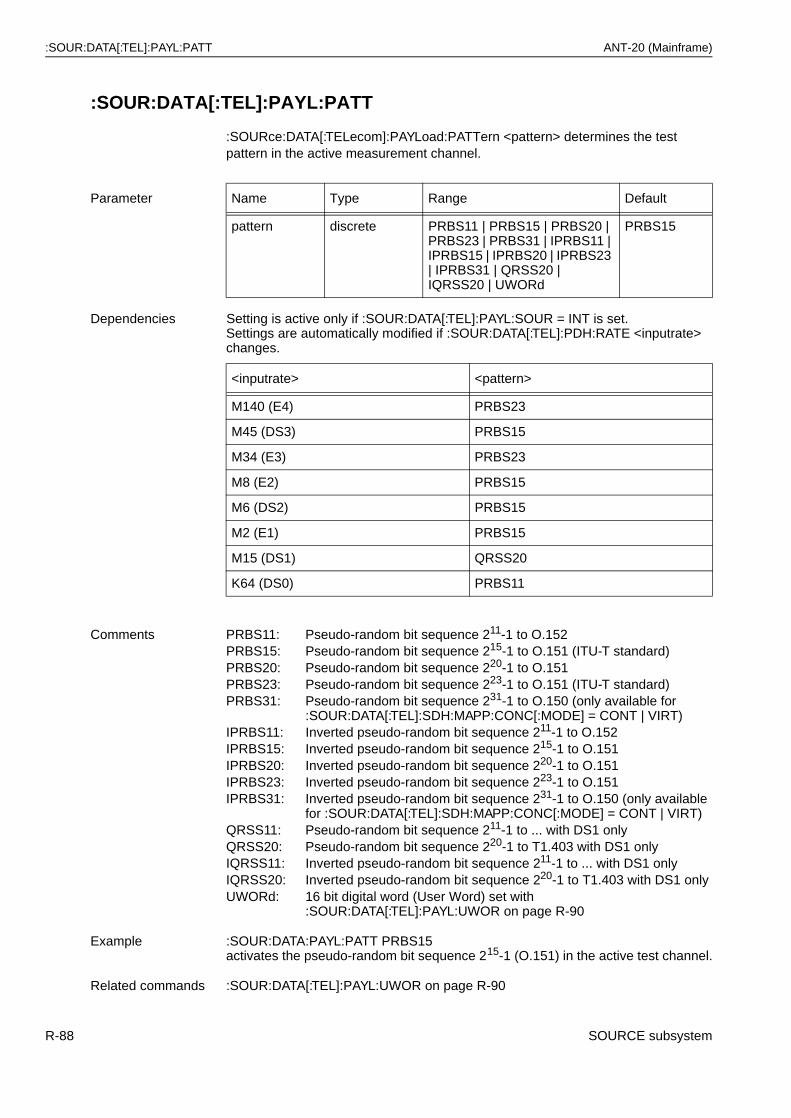
:SOUR:DATA[:TEL]:PAYL:PATT ANT-20 (Mainframe)
:SOUR:DATA[:TEL]:PAYL:PATT
:SOURce:DATA[:TELecom]:PAYLoad:PATTern <pattern> determines the test pattern in the active measurement channel.
Parameter Name Type Range Default
pattern discrete PRBS11 | PRBS15 | PRBS20 | PRBS23 | PRBS31 | IPRBS11 | IPRBS15 | IPRBS20 | IPRBS23 | IPRBS31 | QRSS20 | IQRSS20 | UWORd
PRBS15
Dependencies Setting is active only if :SOUR:DATA[:TEL]:PAYL:SOUR = INT is set.Settings are automatically modified if :SOUR:DATA[:TEL]:PDH:RATE <inputrate> changes.
<inputrate> <pattern>
M140 (E4) PRBS23
M45 (DS3) PRBS15
M34 (E3) PRBS23
M8 (E2) PRBS15
M6 (DS2) PRBS15
M2 (E1) PRBS15
M15 (DS1) QRSS20
K64 (DS0) PRBS11
Comments PRBS11: Pseudo-random bit sequence 211-1 to O.152PRBS15: Pseudo-random bit sequence 215-1 to O.151 (ITU-T standard)PRBS20: Pseudo-random bit sequence 220-1 to O.151PRBS23: Pseudo-random bit sequence 223-1 to O.151 (ITU-T standard)PRBS31: Pseudo-random bit sequence 231-1 to O.150 (only available for
:SOUR:DATA[:TEL]:SDH:MAPP:CONC[:MODE] = CONT | VIRT)IPRBS11: Inverted pseudo-random bit sequence 211-1 to O.152IPRBS15: Inverted pseudo-random bit sequence 215-1 to O.151IPRBS20: Inverted pseudo-random bit sequence 220-1 to O.151IPRBS23: Inverted pseudo-random bit sequence 223-1 to O.151IPRBS31: Inverted pseudo-random bit sequence 231-1 to O.150 (only available
for :SOUR:DATA[:TEL]:SDH:MAPP:CONC[:MODE] = CONT | VIRT)QRSS11: Pseudo-random bit sequence 211-1 to ... with DS1 onlyQRSS20: Pseudo-random bit sequence 220-1 to T1.403 with DS1 onlyIQRSS11: Inverted pseudo-random bit sequence 211-1 to ... with DS1 onlyIQRSS20: Inverted pseudo-random bit sequence 220-1 to T1.403 with DS1 onlyUWORd: 16 bit digital word (User Word) set with
:SOUR:DATA[:TEL]:PAYL:UWOR on page R-90
Example :SOUR:DATA:PAYL:PATT PRBS15activates the pseudo-random bit sequence 215-1 (O.151) in the active test channel.
Related commands :SOUR:DATA[:TEL]:PAYL:UWOR on page R-90
R-88 SOURCE subsystem
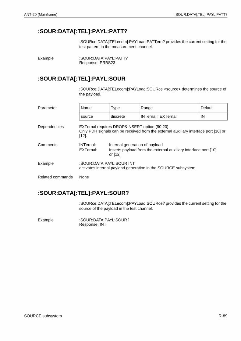
ANT-20 (Mainframe) :SOUR:DATA[:TEL]:PAYL:PATT?
:SOUR:DATA[:TEL]:PAYL:PATT?
:SOURce:DATA[:TELecom]:PAYLoad:PATTern? provides the current setting for the test pattern in the measurement channel.
:SOUR:DATA[:TEL]:PAYL:SOUR
:SOURce:DATA[:TELecom]:PAYLoad:SOURce <source> determines the source of the payload.
:SOUR:DATA[:TEL]:PAYL:SOUR?
:SOURce:DATA[:TELecom]:PAYLoad:SOURce? provides the current setting for the source of the payload in the test channel.
Example :SOUR:DATA:PAYL:PATT?Response: PRBS23
Parameter Name Type Range Default
source discrete INTernal | EXTernal INT
Dependencies EXTernal requires DROP&INSERT option (90.20).Only PDH signals can be received from the external auxiliary interface port [10] or [12].
Comments INTernal: Internal generation of payloadEXTernal: Inserts payload from the external auxiliary interface port [10]
or [12]
Example :SOUR:DATA:PAYL:SOUR INTactivates internal payload generation in the SOURCE subsystem.
Related commands None
Example :SOUR:DATA:PAYL:SOUR?Response: INT
SOURCE subsystem R-89
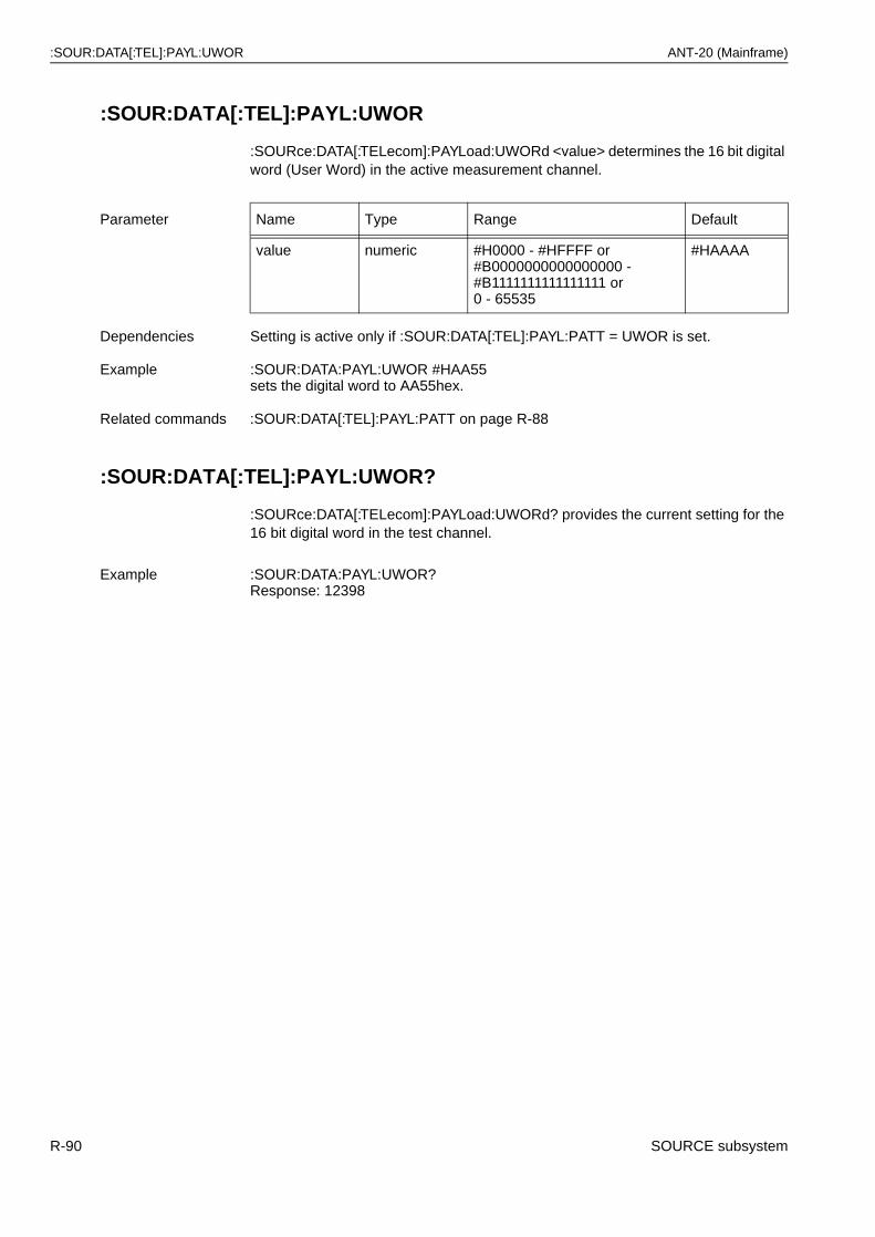
:SOUR:DATA[:TEL]:PAYL:UWOR ANT-20 (Mainframe)
:SOUR:DATA[:TEL]:PAYL:UWOR
:SOURce:DATA[:TELecom]:PAYLoad:UWORd <value> determines the 16 bit digital word (User Word) in the active measurement channel.
:SOUR:DATA[:TEL]:PAYL:UWOR?
:SOURce:DATA[:TELecom]:PAYLoad:UWORd? provides the current setting for the 16 bit digital word in the test channel.
Parameter Name Type Range Default
value numeric #H0000 - #HFFFF or#B0000000000000000 -#B1111111111111111 or0 - 65535
#HAAAA
Dependencies Setting is active only if :SOUR:DATA[:TEL]:PAYL:PATT = UWOR is set.
Example :SOUR:DATA:PAYL:UWOR #HAA55sets the digital word to AA55hex.
Related commands :SOUR:DATA[:TEL]:PAYL:PATT on page R-88
Example :SOUR:DATA:PAYL:UWOR?Response: 12398
R-90 SOURCE subsystem
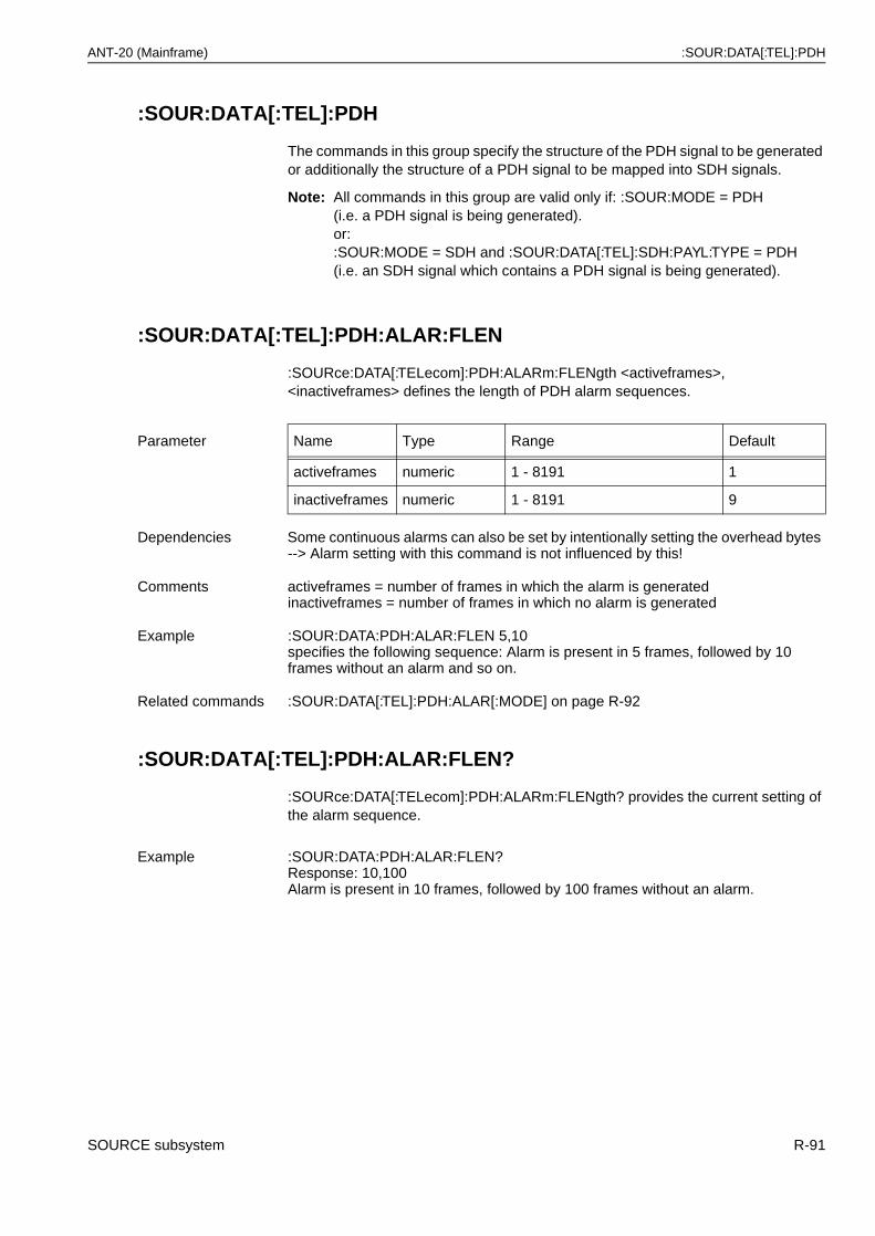
ANT-20 (Mainframe) :SOUR:DATA[:TEL]:PDH
:SOUR:DATA[:TEL]:PDH
The commands in this group specify the structure of the PDH signal to be generated or additionally the structure of a PDH signal to be mapped into SDH signals.
Note: All commands in this group are valid only if: :SOUR:MODE = PDH(i.e. a PDH signal is being generated).or::SOUR:MODE = SDH and :SOUR:DATA[:TEL]:SDH:PAYL:TYPE = PDH(i.e. an SDH signal which contains a PDH signal is being generated).
:SOUR:DATA[:TEL]:PDH:ALAR:FLEN
:SOURce:DATA[:TELecom]:PDH:ALARm:FLENgth <activeframes>, <inactiveframes> defines the length of PDH alarm sequences.
:SOUR:DATA[:TEL]:PDH:ALAR:FLEN?
:SOURce:DATA[:TELecom]:PDH:ALARm:FLENgth? provides the current setting of the alarm sequence.
Parameter Name Type Range Default
activeframes numeric 1 - 8191 1
inactiveframes numeric 1 - 8191 9
Dependencies Some continuous alarms can also be set by intentionally setting the overhead bytes --> Alarm setting with this command is not influenced by this!
Comments activeframes = number of frames in which the alarm is generatedinactiveframes = number of frames in which no alarm is generated
Example :SOUR:DATA:PDH:ALAR:FLEN 5,10specifies the following sequence: Alarm is present in 5 frames, followed by 10 frames without an alarm and so on.
Related commands :SOUR:DATA[:TEL]:PDH:ALAR[:MODE] on page R-92
Example :SOUR:DATA:PDH:ALAR:FLEN?Response: 10,100Alarm is present in 10 frames, followed by 100 frames without an alarm.
SOURCE subsystem R-91
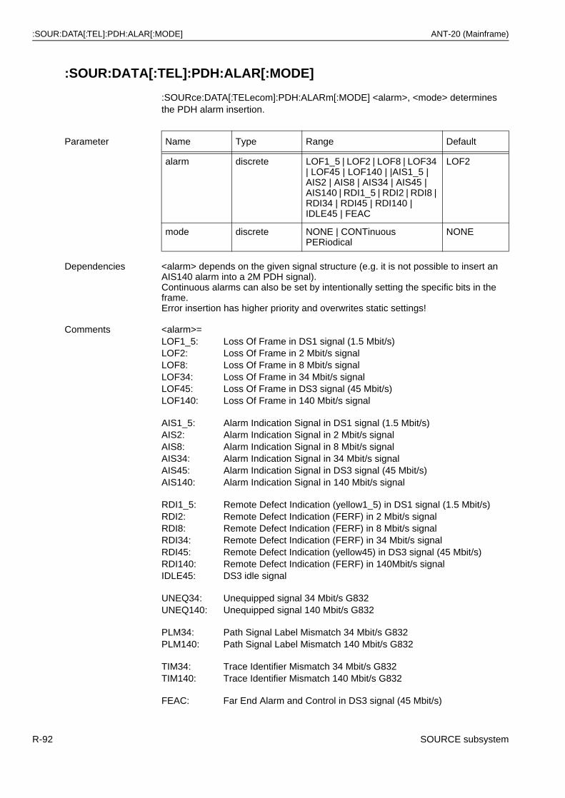
:SOUR:DATA[:TEL]:PDH:ALAR[:MODE] ANT-20 (Mainframe)
:SOUR:DATA[:TEL]:PDH:ALAR[:MODE]
:SOURce:DATA[:TELecom]:PDH:ALARm[:MODE] <alarm>, <mode> determines the PDH alarm insertion.
Parameter Name Type Range Default
alarm discrete LOF1_5 | LOF2 | LOF8 | LOF34 | LOF45 | LOF140 | |AIS1_5 | AIS2 | AIS8 | AIS34 | AIS45 | AIS140 | RDI1_5 | RDI2 | RDI8 | RDI34 | RDI45 | RDI140 | IDLE45 | FEAC
LOF2
mode discrete NONE | CONTinuousPERiodical
NONE
Dependencies <alarm> depends on the given signal structure (e.g. it is not possible to insert an AIS140 alarm into a 2M PDH signal).Continuous alarms can also be set by intentionally setting the specific bits in the frame.Error insertion has higher priority and overwrites static settings!
Comments <alarm>=LOF1_5: Loss Of Frame in DS1 signal (1.5 Mbit/s)LOF2: Loss Of Frame in 2 Mbit/s signalLOF8: Loss Of Frame in 8 Mbit/s signalLOF34: Loss Of Frame in 34 Mbit/s signalLOF45: Loss Of Frame in DS3 signal (45 Mbit/s)LOF140: Loss Of Frame in 140 Mbit/s signal
AIS1_5: Alarm Indication Signal in DS1 signal (1.5 Mbit/s)AIS2: Alarm Indication Signal in 2 Mbit/s signalAIS8: Alarm Indication Signal in 8 Mbit/s signalAIS34: Alarm Indication Signal in 34 Mbit/s signalAIS45: Alarm Indication Signal in DS3 signal (45 Mbit/s)AIS140: Alarm Indication Signal in 140 Mbit/s signal
RDI1_5: Remote Defect Indication (yellow1_5) in DS1 signal (1.5 Mbit/s)RDI2: Remote Defect Indication (FERF) in 2 Mbit/s signalRDI8: Remote Defect Indication (FERF) in 8 Mbit/s signalRDI34: Remote Defect Indication (FERF) in 34 Mbit/s signalRDI45: Remote Defect Indication (yellow45) in DS3 signal (45 Mbit/s)RDI140: Remote Defect Indication (FERF) in 140Mbit/s signalIDLE45: DS3 idle signal
UNEQ34: Unequipped signal 34 Mbit/s G832UNEQ140: Unequipped signal 140 Mbit/s G832
PLM34: Path Signal Label Mismatch 34 Mbit/s G832PLM140: Path Signal Label Mismatch 140 Mbit/s G832
TIM34: Trace Identifier Mismatch 34 Mbit/s G832TIM140: Trace Identifier Mismatch 140 Mbit/s G832
FEAC: Far End Alarm and Control in DS3 signal (45 Mbit/s)
R-92 SOURCE subsystem
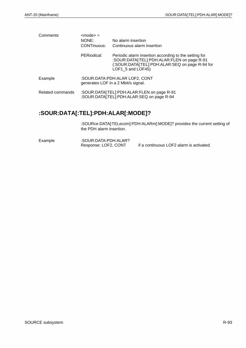
ANT-20 (Mainframe) :SOUR:DATA[:TEL]:PDH:ALAR[:MODE]?
:SOUR:DATA[:TEL]:PDH:ALAR[:MODE]?
:SOURce:DATA[:TELecom]:PDH:ALARm[:MODE]? provides the current setting of the PDH alarm insertion.
Comments <mode> =NONE: No alarm insertionCONTinuous: Continuous alarm insertion
PERiodical: Periodic alarm insertion according to the setting for :SOUR:DATA[:TEL]:PDH:ALAR:FLEN on page R-91(:SOUR:DATA[:TEL]:PDH:ALAR:SEQ on page R-94 forLOF1_5 and LOF45)
Example :SOUR:DATA:PDH:ALAR LOF2, CONTgenerates LOF in a 2 Mbit/s signal.
Related commands :SOUR:DATA[:TEL]:PDH:ALAR:FLEN on page R-91:SOUR:DATA[:TEL]:PDH:ALAR:SEQ on page R-94
Example :SOUR:DATA:PDH:ALAR?Response: LOF2, CONT if a continuous LOF2 alarm is activated.
SOURCE subsystem R-93
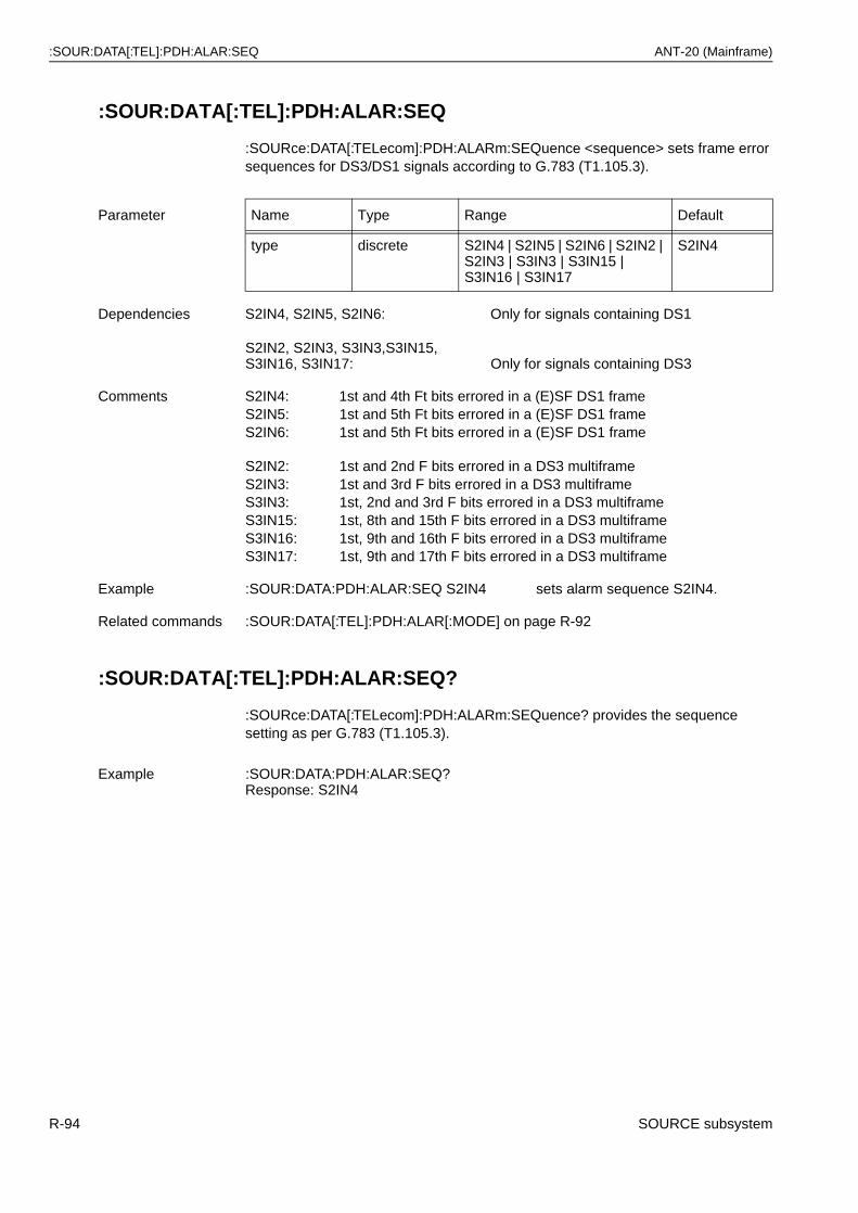
:SOUR:DATA[:TEL]:PDH:ALAR:SEQ ANT-20 (Mainframe)
:SOUR:DATA[:TEL]:PDH:ALAR:SEQ
:SOURce:DATA[:TELecom]:PDH:ALARm:SEQuence <sequence> sets frame error sequences for DS3/DS1 signals according to G.783 (T1.105.3).
:SOUR:DATA[:TEL]:PDH:ALAR:SEQ?
:SOURce:DATA[:TELecom]:PDH:ALARm:SEQuence? provides the sequence setting as per G.783 (T1.105.3).
Parameter Name Type Range Default
type discrete S2IN4 | S2IN5 | S2IN6 | S2IN2 | S2IN3 | S3IN3 | S3IN15 | S3IN16 | S3IN17
S2IN4
Dependencies S2IN4, S2IN5, S2IN6: Only for signals containing DS1
S2IN2, S2IN3, S3IN3,S3IN15, S3IN16, S3IN17: Only for signals containing DS3
Comments S2IN4: 1st and 4th Ft bits errored in a (E)SF DS1 frameS2IN5: 1st and 5th Ft bits errored in a (E)SF DS1 frameS2IN6: 1st and 5th Ft bits errored in a (E)SF DS1 frame
S2IN2: 1st and 2nd F bits errored in a DS3 multiframeS2IN3: 1st and 3rd F bits errored in a DS3 multiframeS3IN3: 1st, 2nd and 3rd F bits errored in a DS3 multiframeS3IN15: 1st, 8th and 15th F bits errored in a DS3 multiframeS3IN16: 1st, 9th and 16th F bits errored in a DS3 multiframeS3IN17: 1st, 9th and 17th F bits errored in a DS3 multiframe
Example :SOUR:DATA:PDH:ALAR:SEQ S2IN4 sets alarm sequence S2IN4.
Related commands :SOUR:DATA[:TEL]:PDH:ALAR[:MODE] on page R-92
Example :SOUR:DATA:PDH:ALAR:SEQ?Response: S2IN4
R-94 SOURCE subsystem
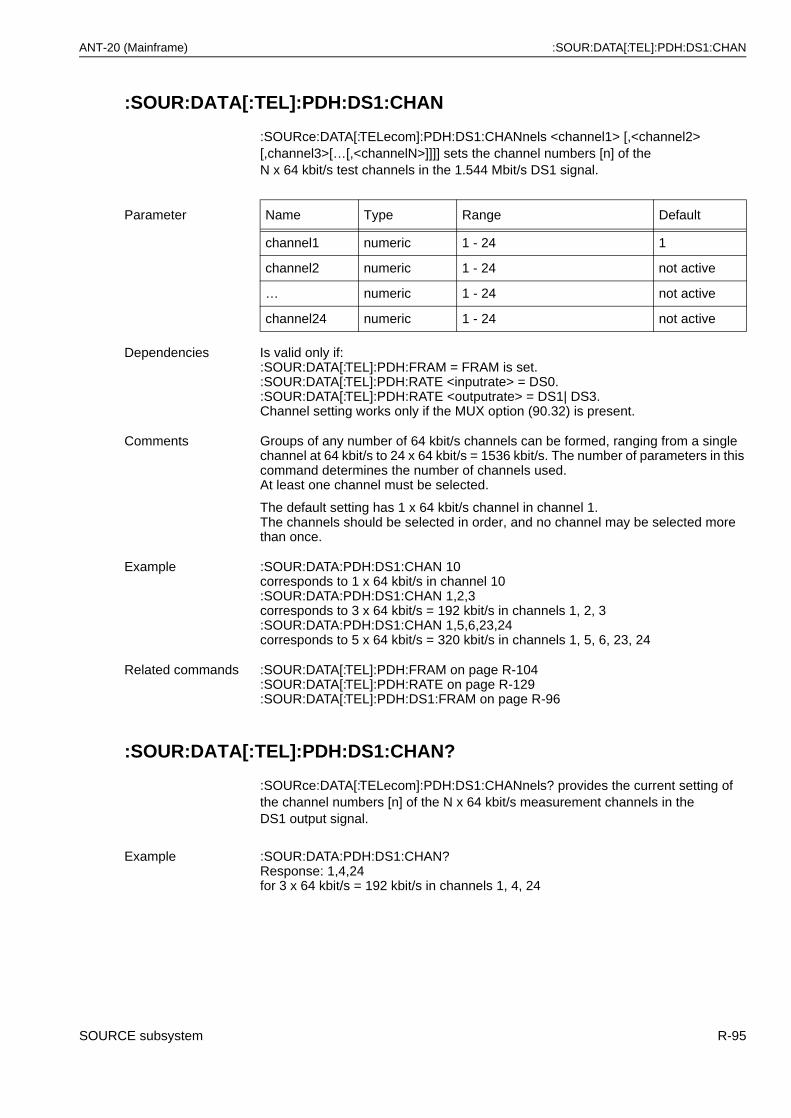
ANT-20 (Mainframe) :SOUR:DATA[:TEL]:PDH:DS1:CHAN
:SOUR:DATA[:TEL]:PDH:DS1:CHAN
:SOURce:DATA[:TELecom]:PDH:DS1:CHANnels <channel1> [,<channel2> [,channel3>[…[,<channelN>]]]] sets the channel numbers [n] of theN x 64 kbit/s test channels in the 1.544 Mbit/s DS1 signal.
:SOUR:DATA[:TEL]:PDH:DS1:CHAN?
:SOURce:DATA[:TELecom]:PDH:DS1:CHANnels? provides the current setting of the channel numbers [n] of the N x 64 kbit/s measurement channels in theDS1 output signal.
Parameter Name Type Range Default
channel1 numeric 1 - 24 1
channel2 numeric 1 - 24 not active
… numeric 1 - 24 not active
channel24 numeric 1 - 24 not active
Dependencies Is valid only if::SOUR:DATA[:TEL]:PDH:FRAM = FRAM is set.:SOUR:DATA[:TEL]:PDH:RATE <inputrate> = DS0.:SOUR:DATA[:TEL]:PDH:RATE <outputrate> = DS1| DS3.Channel setting works only if the MUX option (90.32) is present.
Comments Groups of any number of 64 kbit/s channels can be formed, ranging from a single channel at 64 kbit/s to 24 x 64 kbit/s = 1536 kbit/s. The number of parameters in this command determines the number of channels used.At least one channel must be selected.
The default setting has 1 x 64 kbit/s channel in channel 1.The channels should be selected in order, and no channel may be selected more than once.
Example :SOUR:DATA:PDH:DS1:CHAN 10corresponds to 1 x 64 kbit/s in channel 10:SOUR:DATA:PDH:DS1:CHAN 1,2,3corresponds to 3 x 64 kbit/s = 192 kbit/s in channels 1, 2, 3:SOUR:DATA:PDH:DS1:CHAN 1,5,6,23,24corresponds to 5 x 64 kbit/s = 320 kbit/s in channels 1, 5, 6, 23, 24
Related commands :SOUR:DATA[:TEL]:PDH:FRAM on page R-104:SOUR:DATA[:TEL]:PDH:RATE on page R-129:SOUR:DATA[:TEL]:PDH:DS1:FRAM on page R-96
Example :SOUR:DATA:PDH:DS1:CHAN?Response: 1,4,24for 3 x 64 kbit/s = 192 kbit/s in channels 1, 4, 24
SOURCE subsystem R-95
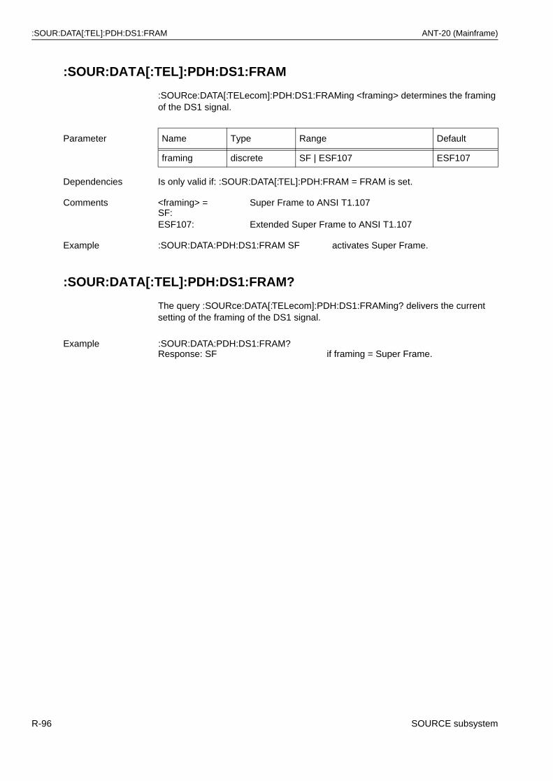
:SOUR:DATA[:TEL]:PDH:DS1:FRAM ANT-20 (Mainframe)
:SOUR:DATA[:TEL]:PDH:DS1:FRAM
:SOURce:DATA[:TELecom]:PDH:DS1:FRAMing <framing> determines the framing of the DS1 signal.
:SOUR:DATA[:TEL]:PDH:DS1:FRAM?
The query :SOURce:DATA[:TELecom]:PDH:DS1:FRAMing? delivers the current setting of the framing of the DS1 signal.
Parameter Name Type Range Default
framing discrete SF | ESF107 ESF107
Dependencies Is only valid if: :SOUR:DATA[:TEL]:PDH:FRAM = FRAM is set.
Comments <framing> = SF:
Super Frame to ANSI T1.107
ESF107: Extended Super Frame to ANSI T1.107
Example :SOUR:DATA:PDH:DS1:FRAM SF activates Super Frame.
Example :SOUR:DATA:PDH:DS1:FRAM?Response: SF if framing = Super Frame.
R-96 SOURCE subsystem
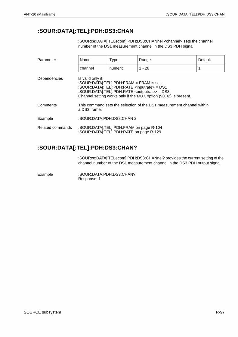
ANT-20 (Mainframe) :SOUR:DATA[:TEL]:PDH:DS3:CHAN
:SOUR:DATA[:TEL]:PDH:DS3:CHAN
:SOURce:DATA[:TELecom]:PDH:DS3:CHANnel <channel> sets the channel number of the DS1 measurement channel in the DS3 PDH signal.
:SOUR:DATA[:TEL]:PDH:DS3:CHAN?
:SOURce:DATA[:TELecom]:PDH:DS3:CHANnel? provides the current setting of the channel number of the DS1 measurement channel in the DS3 PDH output signal.
Parameter Name Type Range Default
channel numeric 1 - 28 1
Dependencies Is valid only if::SOUR:DATA[:TEL]:PDH:FRAM = FRAM is set.:SOUR:DATA[:TEL]:PDH:RATE <inputrate> = DS1:SOUR:DATA[:TEL]:PDH:RATE <outputrate> = DS3 Channel setting works only if the MUX option (90.32) is present.
Comments This command sets the selection of the DS1 measurement channel within a DS3 frame.
Example :SOUR:DATA:PDH:DS3:CHAN 2
Related commands :SOUR:DATA[:TEL]:PDH:FRAM on page R-104:SOUR:DATA[:TEL]:PDH:RATE on page R-129
Example :SOUR:DATA:PDH:DS3:CHAN?Response: 1
SOURCE subsystem R-97
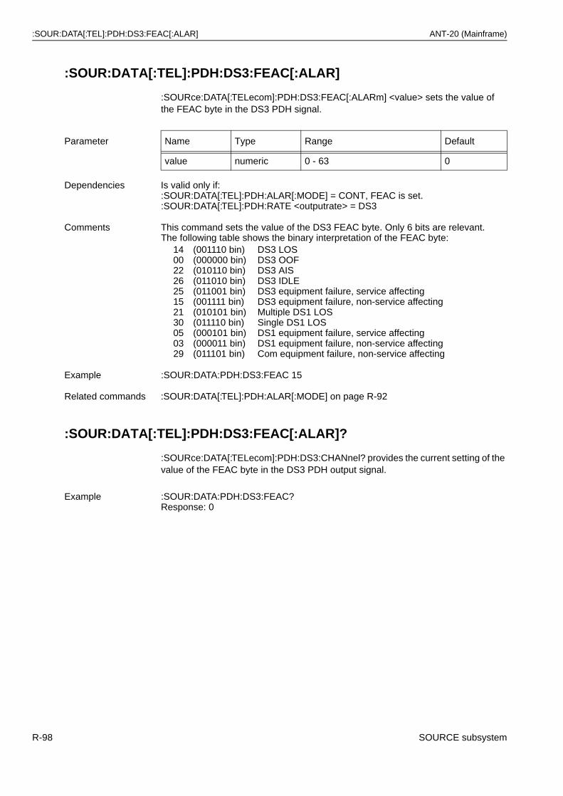
:SOUR:DATA[:TEL]:PDH:DS3:FEAC[:ALAR] ANT-20 (Mainframe)
:SOUR:DATA[:TEL]:PDH:DS3:FEAC[:ALAR]
:SOURce:DATA[:TELecom]:PDH:DS3:FEAC[:ALARm] <value> sets the value of the FEAC byte in the DS3 PDH signal.
:SOUR:DATA[:TEL]:PDH:DS3:FEAC[:ALAR]?
:SOURce:DATA[:TELecom]:PDH:DS3:CHANnel? provides the current setting of the value of the FEAC byte in the DS3 PDH output signal.
Parameter Name Type Range Default
value numeric 0 - 63 0
Dependencies Is valid only if::SOUR:DATA[:TEL]:PDH:ALAR[:MODE] = CONT, FEAC is set.:SOUR:DATA[:TEL]:PDH:RATE <outputrate> = DS3
Comments This command sets the value of the DS3 FEAC byte. Only 6 bits are relevant. The following table shows the binary interpretation of the FEAC byte:
1400222625152130050329
(001110 bin)(000000 bin)(010110 bin)(011010 bin)(011001 bin)(001111 bin)(010101 bin)(011110 bin)(000101 bin)(000011 bin)(011101 bin)
DS3 LOSDS3 OOFDS3 AISDS3 IDLEDS3 equipment failure, service affectingDS3 equipment failure, non-service affectingMultiple DS1 LOSSingle DS1 LOSDS1 equipment failure, service affectingDS1 equipment failure, non-service affectingCom equipment failure, non-service affecting
Example :SOUR:DATA:PDH:DS3:FEAC 15
Related commands :SOUR:DATA[:TEL]:PDH:ALAR[:MODE] on page R-92
Example :SOUR:DATA:PDH:DS3:FEAC?Response: 0
R-98 SOURCE subsystem
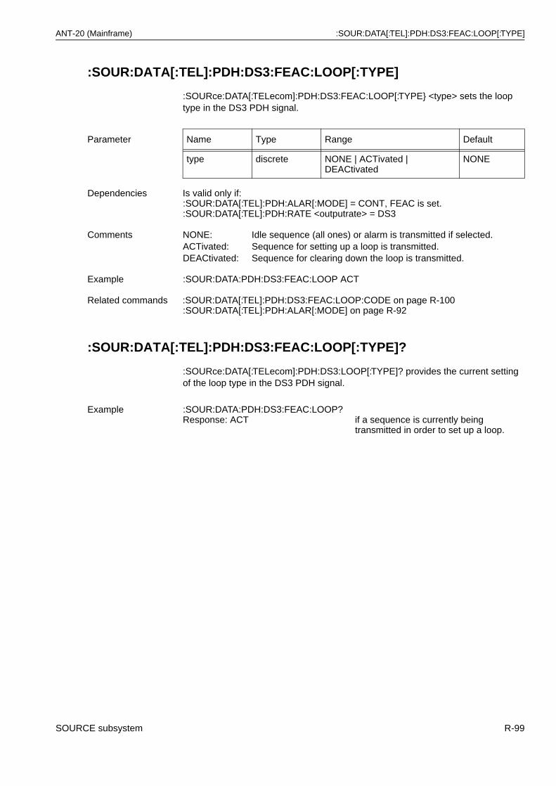
ANT-20 (Mainframe) :SOUR:DATA[:TEL]:PDH:DS3:FEAC:LOOP[:TYPE]
:SOUR:DATA[:TEL]:PDH:DS3:FEAC:LOOP[:TYPE]
:SOURce:DATA[:TELecom]:PDH:DS3:FEAC:LOOP[:TYPE} <type> sets the loop type in the DS3 PDH signal.
:SOUR:DATA[:TEL]:PDH:DS3:FEAC:LOOP[:TYPE]?
:SOURce:DATA[:TELecom]:PDH:DS3:LOOP[:TYPE]? provides the current setting of the loop type in the DS3 PDH signal.
Parameter Name Type Range Default
type discrete NONE | ACTivated | DEACtivated
NONE
Dependencies Is valid only if: :SOUR:DATA[:TEL]:PDH:ALAR[:MODE] = CONT, FEAC is set.:SOUR:DATA[:TEL]:PDH:RATE <outputrate> = DS3
Comments NONE: Idle sequence (all ones) or alarm is transmitted if selected.ACTivated: Sequence for setting up a loop is transmitted.DEACtivated: Sequence for clearing down the loop is transmitted.
Example :SOUR:DATA:PDH:DS3:FEAC:LOOP ACT
Related commands :SOUR:DATA[:TEL]:PDH:DS3:FEAC:LOOP:CODE on page R-100:SOUR:DATA[:TEL]:PDH:ALAR[:MODE] on page R-92
Example :SOUR:DATA:PDH:DS3:FEAC:LOOP?Response: ACT if a sequence is currently being
transmitted in order to set up a loop.
SOURCE subsystem R-99
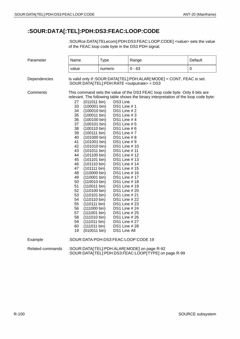
:SOUR:DATA[:TEL]:PDH:DS3:FEAC:LOOP:CODE ANT-20 (Mainframe)
:SOUR:DATA[:TEL]:PDH:DS3:FEAC:LOOP:CODE
:SOURce:DATA[:TELecom]:PDH:DS3:FEAC:LOOP:CODE] <value> sets the value of the FEAC loop code byte in the DS3 PDH signal.
Parameter Name Type Range Default
value numeric 0 - 63 0
Dependencies Is valid only if::SOUR:DATA[:TEL]:PDH:ALAR[:MODE] = CONT, FEAC is set.:SOUR:DATA[:TEL]:PDH:RATE <outputrate> = DS3
Comments This command sets the value of the DS3 FEAC loop code byte. Only 6 bits are relevant. The following table shows the binary interpretation of the loop code byte:
273334353637383940414243444546474849505152535455565758596019
(011011 bin)(100001 bin)(100010 bin)(100011 bin)(100100 bin)(100101 bin) (100110 bin)(100111 bin)(101000 bin)(101001 bin)(101010 bin)(101011 bin)(101100 bin)(101101 bin)(101110 bin)(101111 bin)(110000 bin)(110001 bin)(110010 bin)(110011 bin)(110100 bin)(110101 bin)(110110 bin)(110111 bin)(111000 bin)(111001 bin)(111010 bin)(111011 bin)(111011 bin)(010011 bin)
DS3 LineDS1 Line # 1DS1 Line # 2DS1 Line # 3DS1 Line # 4DS1 Line # 5DS1 Line # 6DS1 Line # 7DS1 Line # 8DS1 Line # 9DS1 Line # 10DS1 Line # 11DS1 Line # 12DS1 Line # 13DS1 Line # 14DS1 Line # 15DS1 Line # 16DS1 Line # 17DS1 Line # 18DS1 Line # 19DS1 Line # 20DS1 Line # 21DS1 Line # 22DS1 Line # 23DS1 Line # 24DS1 Line # 25DS1 Line # 26DS1 Line # 27DS1 Line # 28DS1 Line All
Example :SOUR:DATA:PDH:DS3:FEAC:LOOP:CODE 19
Related commands :SOUR:DATA[:TEL]:PDH:ALAR[:MODE] on page R-92:SOUR:DATA[:TEL]:PDH:DS3:FEAC:LOOP[:TYPE] on page R-99
R-100 SOURCE subsystem
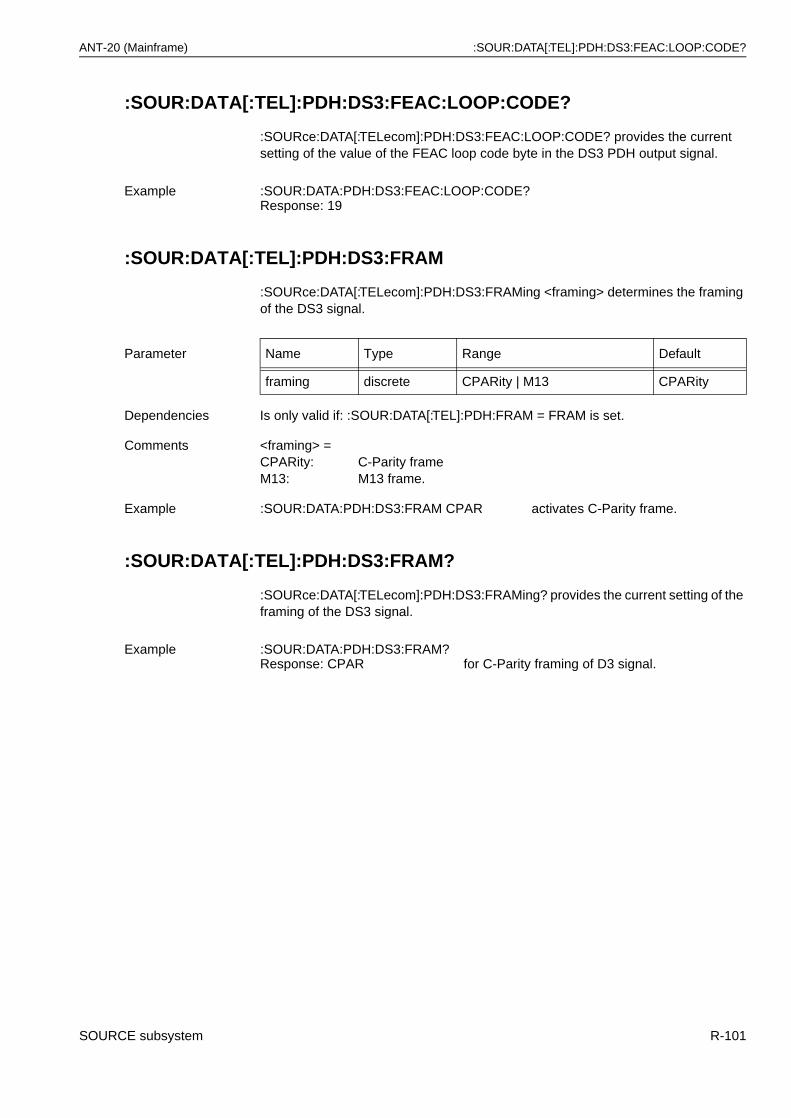
ANT-20 (Mainframe) :SOUR:DATA[:TEL]:PDH:DS3:FEAC:LOOP:CODE?
:SOUR:DATA[:TEL]:PDH:DS3:FEAC:LOOP:CODE?
:SOURce:DATA[:TELecom]:PDH:DS3:FEAC:LOOP:CODE? provides the current setting of the value of the FEAC loop code byte in the DS3 PDH output signal.
:SOUR:DATA[:TEL]:PDH:DS3:FRAM
:SOURce:DATA[:TELecom]:PDH:DS3:FRAMing <framing> determines the framing of the DS3 signal.
:SOUR:DATA[:TEL]:PDH:DS3:FRAM?
:SOURce:DATA[:TELecom]:PDH:DS3:FRAMing? provides the current setting of the framing of the DS3 signal.
Example :SOUR:DATA:PDH:DS3:FEAC:LOOP:CODE?Response: 19
Parameter Name Type Range Default
framing discrete CPARity | M13 CPARity
Dependencies Is only valid if: :SOUR:DATA[:TEL]:PDH:FRAM = FRAM is set.
Comments <framing> =CPARity: C-Parity frameM13: M13 frame.
Example :SOUR:DATA:PDH:DS3:FRAM CPAR activates C-Parity frame.
Example :SOUR:DATA:PDH:DS3:FRAM?Response: CPAR for C-Parity framing of D3 signal.
SOURCE subsystem R-101
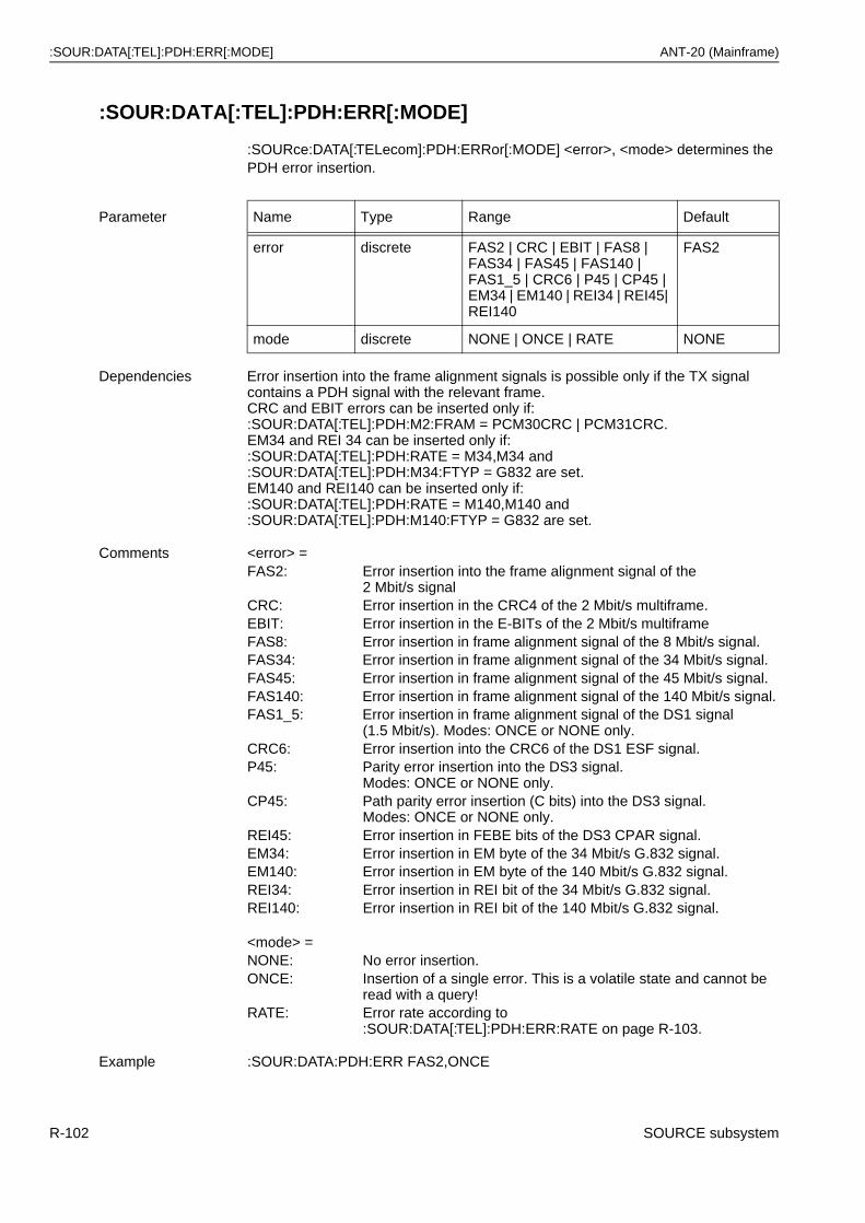
:SOUR:DATA[:TEL]:PDH:ERR[:MODE] ANT-20 (Mainframe)
:SOUR:DATA[:TEL]:PDH:ERR[:MODE]
:SOURce:DATA[:TELecom]:PDH:ERRor[:MODE] <error>, <mode> determines the PDH error insertion.
Parameter Name Type Range Default
error discrete FAS2 | CRC | EBIT | FAS8 | FAS34 | FAS45 | FAS140 | FAS1_5 | CRC6 | P45 | CP45 | EM34 | EM140 | REI34 | REI45| REI140
FAS2
mode discrete NONE | ONCE | RATE NONE
Dependencies Error insertion into the frame alignment signals is possible only if the TX signal contains a PDH signal with the relevant frame.CRC and EBIT errors can be inserted only if::SOUR:DATA[:TEL]:PDH:M2:FRAM = PCM30CRC | PCM31CRC.EM34 and REI 34 can be inserted only if::SOUR:DATA[:TEL]:PDH:RATE = M34,M34 and:SOUR:DATA[:TEL]:PDH:M34:FTYP = G832 are set.EM140 and REI140 can be inserted only if::SOUR:DATA[:TEL]:PDH:RATE = M140,M140 and:SOUR:DATA[:TEL]:PDH:M140:FTYP = G832 are set.
Comments <error> =FAS2: Error insertion into the frame alignment signal of the
2 Mbit/s signalCRC: Error insertion in the CRC4 of the 2 Mbit/s multiframe.EBIT: Error insertion in the E-BITs of the 2 Mbit/s multiframeFAS8: Error insertion in frame alignment signal of the 8 Mbit/s signal.FAS34: Error insertion in frame alignment signal of the 34 Mbit/s signal.FAS45: Error insertion in frame alignment signal of the 45 Mbit/s signal.FAS140: Error insertion in frame alignment signal of the 140 Mbit/s signal.FAS1_5: Error insertion in frame alignment signal of the DS1 signal
(1.5 Mbit/s). Modes: ONCE or NONE only.CRC6: Error insertion into the CRC6 of the DS1 ESF signal.P45: Parity error insertion into the DS3 signal.
Modes: ONCE or NONE only.CP45: Path parity error insertion (C bits) into the DS3 signal.
Modes: ONCE or NONE only.REI45: Error insertion in FEBE bits of the DS3 CPAR signal.EM34: Error insertion in EM byte of the 34 Mbit/s G.832 signal.EM140: Error insertion in EM byte of the 140 Mbit/s G.832 signal.REI34: Error insertion in REI bit of the 34 Mbit/s G.832 signal.REI140: Error insertion in REI bit of the 140 Mbit/s G.832 signal.
<mode> =NONE: No error insertion.ONCE: Insertion of a single error. This is a volatile state and cannot be
read with a query!RATE: Error rate according to
:SOUR:DATA[:TEL]:PDH:ERR:RATE on page R-103.
Example :SOUR:DATA:PDH:ERR FAS2,ONCE
R-102 SOURCE subsystem
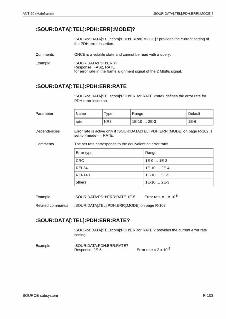
ANT-20 (Mainframe) :SOUR:DATA[:TEL]:PDH:ERR[:MODE]?
:SOUR:DATA[:TEL]:PDH:ERR[:MODE]?
:SOURce:DATA[:TELecom]:PDH:ERRor[:MODE]? provides the current setting of the PDH error insertion.
:SOUR:DATA[:TEL]:PDH:ERR:RATE
:SOURce:DATA[:TELecom]:PDH:ERRor:RATE <rate> defines the error rate for PDH error insertion.
:SOUR:DATA[:TEL]:PDH:ERR:RATE?
:SOURce:DATA[:TELecom]:PDH:ERRor:RATE ? provides the current error rate setting.
Comments ONCE is a volatile state and cannot be read with a query.
Example :SOUR:DATA:PDH:ERR?Response: FAS2, RATEfor error rate in the frame alignment signal of the 2 Mbit/s signal.
Parameter Name Type Range Default
rate NR3 1E-10 … 2E-3 1E-6
Dependencies Error rate is active only if :SOUR:DATA[:TEL]:PDH:ERR[:MODE] on page R-102 is set to <mode> = RATE.
Comments The set rate corresponds to the equivalent bit error rate!
Error type Range
CRC 1E-9 … 1E-3
REI-34 1E-10 … 2E-4
REI-140 1E-10 … 5E-5
others 1E-10 … 2E-3
Example :SOUR:DATA:PDH:ERR:RATE 1E-5 Error rate = 1 x 10⁻⁵
Related commands :SOUR:DATA[:TEL]:PDH:ERR[:MODE] on page R-102
Example :SOUR:DATA:PDH:ERR:RATE?Response: 2E-5 Error rate = 2 x 10⁻⁵
SOURCE subsystem R-103
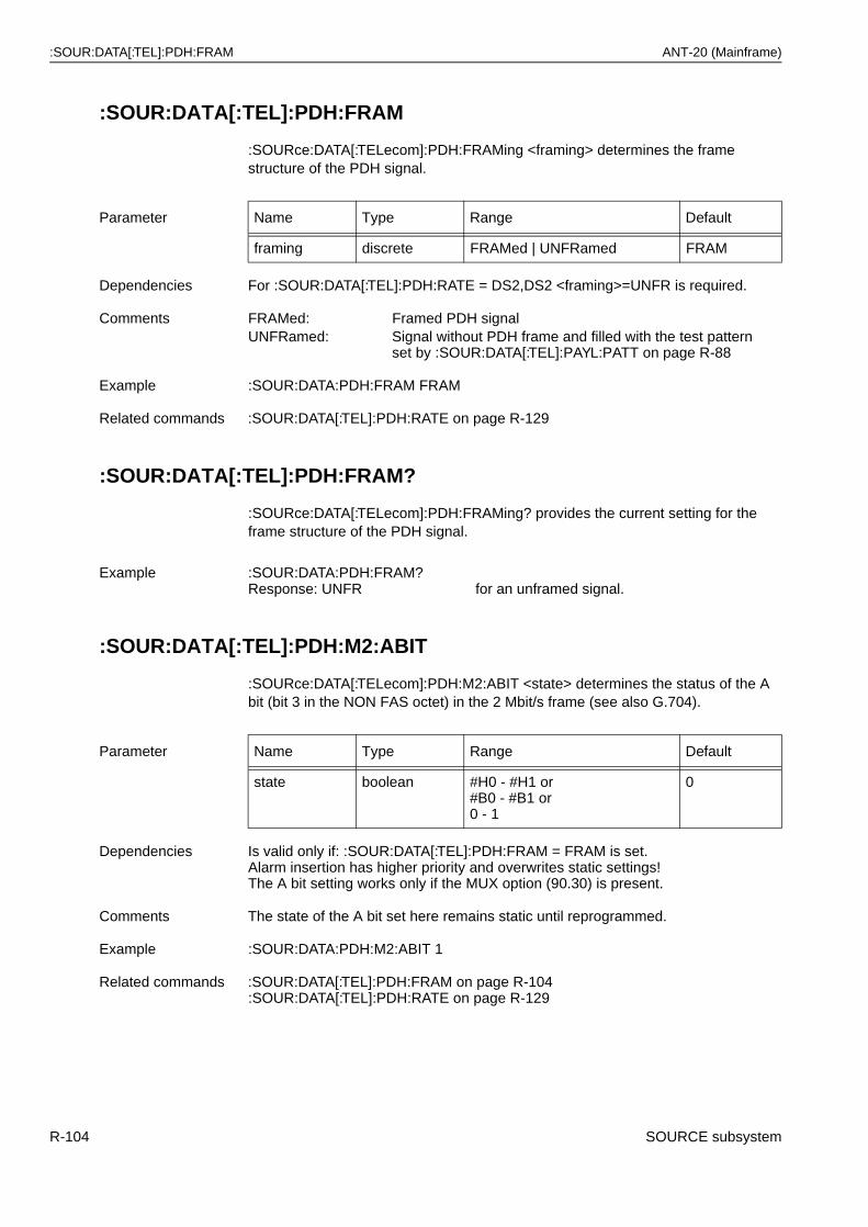
:SOUR:DATA[:TEL]:PDH:FRAM ANT-20 (Mainframe)
:SOUR:DATA[:TEL]:PDH:FRAM
:SOURce:DATA[:TELecom]:PDH:FRAMing <framing> determines the frame structure of the PDH signal.
:SOUR:DATA[:TEL]:PDH:FRAM?
:SOURce:DATA[:TELecom]:PDH:FRAMing? provides the current setting for the frame structure of the PDH signal.
:SOUR:DATA[:TEL]:PDH:M2:ABIT
:SOURce:DATA[:TELecom]:PDH:M2:ABIT <state> determines the status of the A bit (bit 3 in the NON FAS octet) in the 2 Mbit/s frame (see also G.704).
Parameter Name Type Range Default
framing discrete FRAMed | UNFRamed FRAM
Dependencies For :SOUR:DATA[:TEL]:PDH:RATE = DS2,DS2 <framing>=UNFR is required.
Comments FRAMed: Framed PDH signalUNFRamed: Signal without PDH frame and filled with the test pattern
set by :SOUR:DATA[:TEL]:PAYL:PATT on page R-88
Example :SOUR:DATA:PDH:FRAM FRAM
Related commands :SOUR:DATA[:TEL]:PDH:RATE on page R-129
Example :SOUR:DATA:PDH:FRAM?Response: UNFR for an unframed signal.
Parameter Name Type Range Default
state boolean #H0 - #H1 or#B0 - #B1 or0 - 1
0
Dependencies Is valid only if: :SOUR:DATA[:TEL]:PDH:FRAM = FRAM is set.Alarm insertion has higher priority and overwrites static settings!The A bit setting works only if the MUX option (90.30) is present.
Comments The state of the A bit set here remains static until reprogrammed.
Example :SOUR:DATA:PDH:M2:ABIT 1
Related commands :SOUR:DATA[:TEL]:PDH:FRAM on page R-104:SOUR:DATA[:TEL]:PDH:RATE on page R-129
R-104 SOURCE subsystem
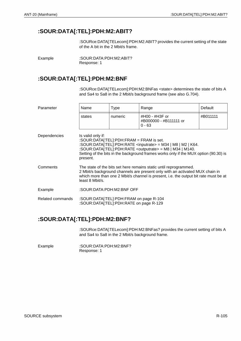
ANT-20 (Mainframe) :SOUR:DATA[:TEL]:PDH:M2:ABIT?
:SOUR:DATA[:TEL]:PDH:M2:ABIT?
:SOURce:DATA[:TELecom]:PDH:M2:ABIT? provides the current setting of the state of the A bit in the 2 Mbit/s frame.
:SOUR:DATA[:TEL]:PDH:M2:BNF
:SOURce:DATA[:TELecom]:PDH:M2:BNFas <state> determines the state of bits A and Sa4 to Sa8 in the 2 Mbit/s background frame (see also G.704).
:SOUR:DATA[:TEL]:PDH:M2:BNF?
:SOURce:DATA[:TELecom]:PDH:M2:BNFas? provides the current setting of bits A and Sa4 to Sa8 in the 2 Mbit/s background frame.
Example :SOUR:DATA:PDH:M2:ABIT?Response: 1
Parameter Name Type Range Default
states numeric #H00 - #H3F or#B000000 - #B111111 or0 - 63
#B011111
Dependencies Is valid only if::SOUR:DATA[:TEL]:PDH:FRAM = FRAM is set.:SOUR:DATA[:TEL]:PDH:RATE <inputrate> = M34 | M8 | M2 | K64.:SOUR:DATA[:TEL]:PDH:RATE <outputrate> = M8 | M34 | M140.Setting of the bits in the background frames works only if the MUX option (90.30) is present.
Comments The state of the bits set here remains static until reprogrammed.2 Mbit/s background channels are present only with an activated MUX chain in which more than one 2 Mbit/s channel is present, i.e. the output bit rate must be at least 8 Mbit/s.
Example :SOUR:DATA:PDH:M2:BNF OFF
Related commands :SOUR:DATA[:TEL]:PDH:FRAM on page R-104:SOUR:DATA[:TEL]:PDH:RATE on page R-129
Example :SOUR:DATA:PDH:M2:BNF?Response: 1
SOURCE subsystem R-105
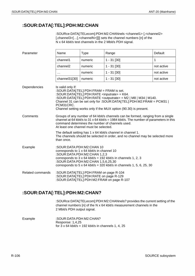
:SOUR:DATA[:TEL]:PDH:M2:CHAN ANT-20 (Mainframe)
:SOUR:DATA[:TEL]:PDH:M2:CHAN
:SOURce:DATA[:TELecom]:PDH:M2:CHANnels <channel1> [,<channel2> [,channel3>[…[,<channelN>]]]] sets the channel numbers [n] of theN x 64 kbit/s test channels in the 2 Mbit/s PDH signal.
:SOUR:DATA[:TEL]:PDH:M2:CHAN?
:SOURce:DATA[:TELecom]:PDH:M2:CHANnels? provides the current setting of the channel numbers [n] of the N x 64 kbit/s measurement channels in the2 Mbit/s PDH output signal.
Parameter Name Type Range Default
channel1 numeric 1 - 31 [30] 1
channel2 numeric 1 - 31 [30] not active
… numeric 1 - 31 [30] not active
channel31[30] numeric 1 - 31 [30] not active
Dependencies Is valid only if::SOUR:DATA[:TEL]:PDH:FRAM = FRAM is set.:SOUR:DATA[:TEL]:PDH:RATE <inputrate> = K64.:SOUR:DATA[:TEL]:PDH:RATE <outputrate> = M2 | M8 | M34 | M140.Channel 31 can be set only for :SOUR:DATA[:TEL]:PDH:M2:FRAM = PCM31 | PCM31CRC.Channel setting works only if the MUX option (90.30) is present.
Comments Groups of any number of 64 kbit/s channels can be formed, ranging from a single channel at 64 kbit/s to 31 x 64 kbit/s = 1984 kbit/s. The number of parameters in this command determines the number of channels used.At least one channel must be selected.
The default setting has 1 x 64 kbit/s channel in channel 1.The channels should be selected in order, and no channel may be selected more than once.
Example :SOUR:DATA:PDH:M2:CHAN 10corresponds to 1 x 64 kbit/s in channel 10:SOUR:DATA:PDH:M2:CHAN 1,2,3corresponds to 3 x 64 kbit/s = 192 kbit/s in channels 1, 2, 3:SOUR:DATA:PDH:M2:CHAN 1,5,6,25,30corresponds to 5 x 64 kbit/s = 320 kbit/s in channels 1, 5, 6, 25, 30
Related commands :SOUR:DATA[:TEL]:PDH:FRAM on page R-104:SOUR:DATA[:TEL]:PDH:RATE on page R-129:SOUR:DATA[:TEL]:PDH:M2:FRAM on page R-107
Example :SOUR:DATA:PDH:M2:CHAN?Response: 1,4,25for 3 x 64 kbit/s = 192 kbit/s in channels 1, 4, 25
R-106 SOURCE subsystem
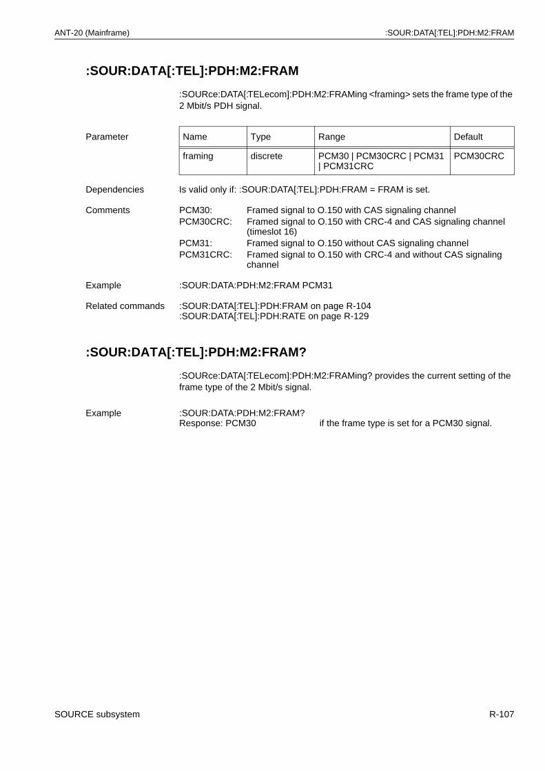
ANT-20 (Mainframe) :SOUR:DATA[:TEL]:PDH:M2:FRAM
:SOUR:DATA[:TEL]:PDH:M2:FRAM
:SOURce:DATA[:TELecom]:PDH:M2:FRAMing <framing> sets the frame type of the 2 Mbit/s PDH signal.
:SOUR:DATA[:TEL]:PDH:M2:FRAM?
:SOURce:DATA[:TELecom]:PDH:M2:FRAMing? provides the current setting of the frame type of the 2 Mbit/s signal.
Parameter Name Type Range Default
framing discrete PCM30 | PCM30CRC | PCM31 | PCM31CRC
PCM30CRC
Dependencies Is valid only if: :SOUR:DATA[:TEL]:PDH:FRAM = FRAM is set.
Comments PCM30: Framed signal to O.150 with CAS signaling channelPCM30CRC: Framed signal to O.150 with CRC-4 and CAS signaling channel
(timeslot 16)PCM31: Framed signal to O.150 without CAS signaling channelPCM31CRC: Framed signal to O.150 with CRC-4 and without CAS signaling
channel
Example :SOUR:DATA:PDH:M2:FRAM PCM31
Related commands :SOUR:DATA[:TEL]:PDH:FRAM on page R-104:SOUR:DATA[:TEL]:PDH:RATE on page R-129
Example :SOUR:DATA:PDH:M2:FRAM?Response: PCM30 if the frame type is set for a PCM30 signal.
SOURCE subsystem R-107
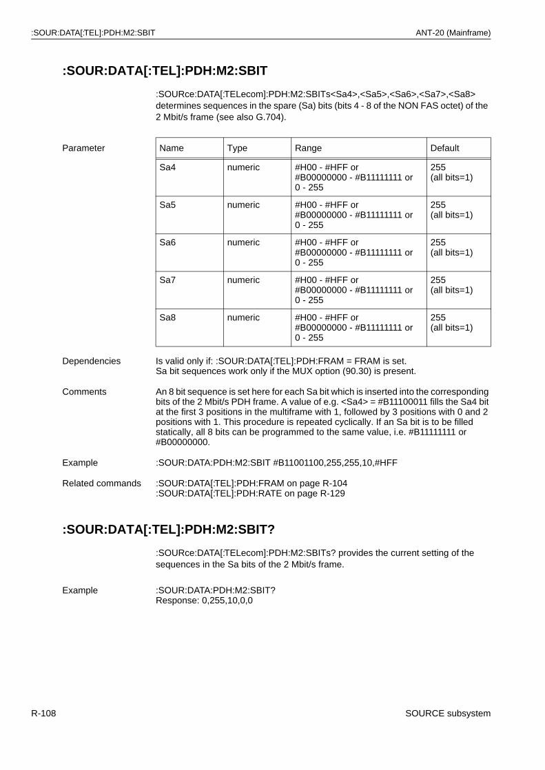
:SOUR:DATA[:TEL]:PDH:M2:SBIT ANT-20 (Mainframe)
:SOUR:DATA[:TEL]:PDH:M2:SBIT
:SOURce:DATA[:TELecom]:PDH:M2:SBITs<Sa4>,<Sa5>,<Sa6>,<Sa7>,<Sa8>determines sequences in the spare (Sa) bits (bits 4 - 8 of the NON FAS octet) of the 2 Mbit/s frame (see also G.704).
:SOUR:DATA[:TEL]:PDH:M2:SBIT?
:SOURce:DATA[:TELecom]:PDH:M2:SBITs? provides the current setting of the sequences in the Sa bits of the 2 Mbit/s frame.
Parameter Name Type Range Default
Sa4 numeric #H00 - #HFF or#B00000000 - #B11111111 or 0 - 255
255(all bits=1)
Sa5 numeric #H00 - #HFF or#B00000000 - #B11111111 or0 - 255
255(all bits=1)
Sa6 numeric #H00 - #HFF or#B00000000 - #B11111111 or0 - 255
255(all bits=1)
Sa7 numeric #H00 - #HFF or#B00000000 - #B11111111 or 0 - 255
255(all bits=1)
Sa8 numeric #H00 - #HFF or#B00000000 - #B11111111 or 0 - 255
255(all bits=1)
Dependencies Is valid only if: :SOUR:DATA[:TEL]:PDH:FRAM = FRAM is set.Sa bit sequences work only if the MUX option (90.30) is present.
Comments An 8 bit sequence is set here for each Sa bit which is inserted into the corresponding bits of the 2 Mbit/s PDH frame. A value of e.g. <Sa4> = #B11100011 fills the Sa4 bit at the first 3 positions in the multiframe with 1, followed by 3 positions with 0 and 2 positions with 1. This procedure is repeated cyclically. If an Sa bit is to be filled statically, all 8 bits can be programmed to the same value, i.e. #B11111111 or #B00000000.
Example :SOUR:DATA:PDH:M2:SBIT #B11001100,255,255,10,#HFF
Related commands :SOUR:DATA[:TEL]:PDH:FRAM on page R-104:SOUR:DATA[:TEL]:PDH:RATE on page R-129
Example :SOUR:DATA:PDH:M2:SBIT?Response: 0,255,10,0,0
R-108 SOURCE subsystem
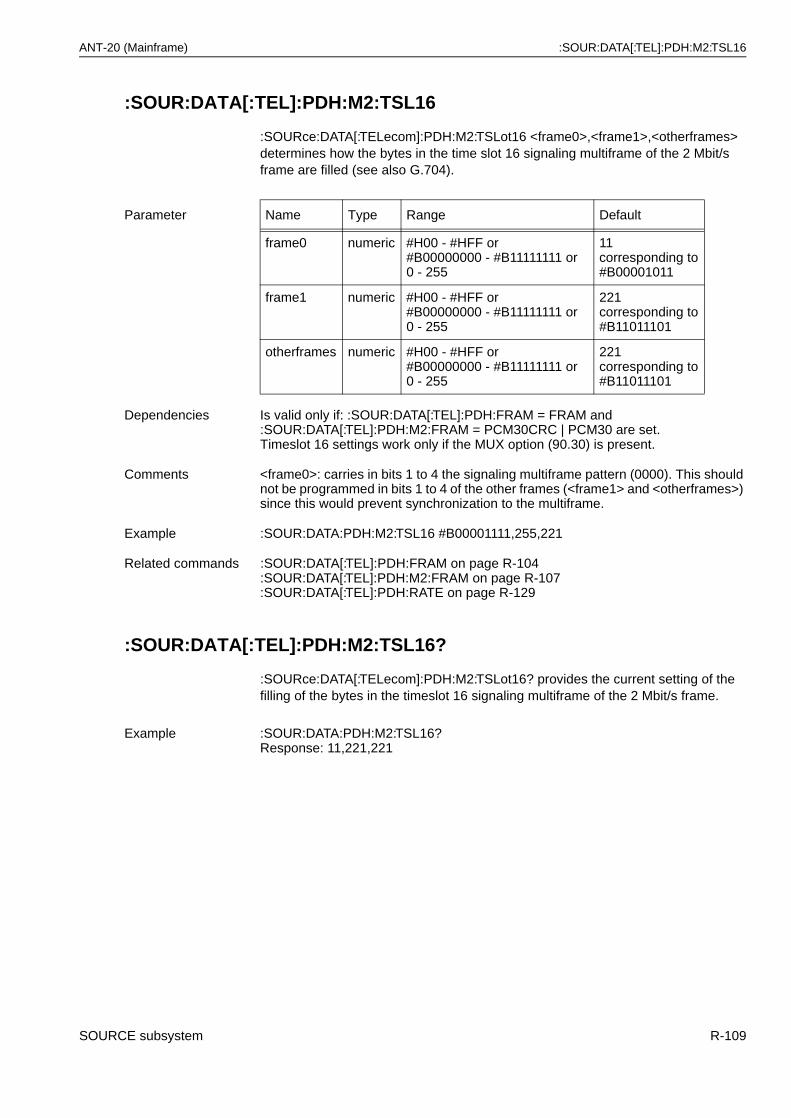
ANT-20 (Mainframe) :SOUR:DATA[:TEL]:PDH:M2:TSL16
:SOUR:DATA[:TEL]:PDH:M2:TSL16
:SOURce:DATA[:TELecom]:PDH:M2:TSLot16 <frame0>,<frame1>,<otherframes> determines how the bytes in the time slot 16 signaling multiframe of the 2 Mbit/s frame are filled (see also G.704).
:SOUR:DATA[:TEL]:PDH:M2:TSL16?
:SOURce:DATA[:TELecom]:PDH:M2:TSLot16? provides the current setting of the filling of the bytes in the timeslot 16 signaling multiframe of the 2 Mbit/s frame.
Parameter Name Type Range Default
frame0 numeric #H00 - #HFF or#B00000000 - #B11111111 or 0 - 255
11corresponding to#B00001011
frame1 numeric #H00 - #HFF or#B00000000 - #B11111111 or 0 - 255
221corresponding to#B11011101
otherframes numeric #H00 - #HFF or#B00000000 - #B11111111 or 0 - 255
221corresponding to#B11011101
Dependencies Is valid only if: :SOUR:DATA[:TEL]:PDH:FRAM = FRAM and :SOUR:DATA[:TEL]:PDH:M2:FRAM = PCM30CRC | PCM30 are set.Timeslot 16 settings work only if the MUX option (90.30) is present.
Comments <frame0>: carries in bits 1 to 4 the signaling multiframe pattern (0000). This should not be programmed in bits 1 to 4 of the other frames (<frame1> and <otherframes>) since this would prevent synchronization to the multiframe.
Example :SOUR:DATA:PDH:M2:TSL16 #B00001111,255,221
Related commands :SOUR:DATA[:TEL]:PDH:FRAM on page R-104:SOUR:DATA[:TEL]:PDH:M2:FRAM on page R-107:SOUR:DATA[:TEL]:PDH:RATE on page R-129
Example :SOUR:DATA:PDH:M2:TSL16?Response: 11,221,221
SOURCE subsystem R-109
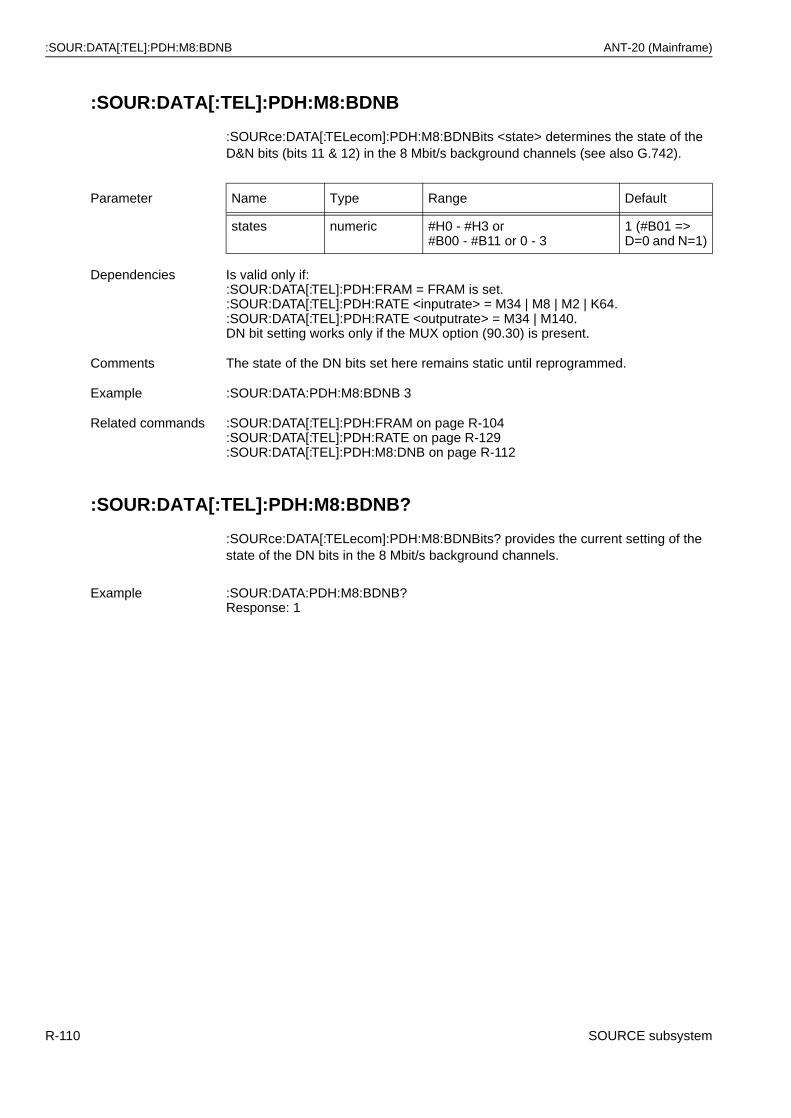
:SOUR:DATA[:TEL]:PDH:M8:BDNB ANT-20 (Mainframe)
:SOUR:DATA[:TEL]:PDH:M8:BDNB
:SOURce:DATA[:TELecom]:PDH:M8:BDNBits <state> determines the state of the D&N bits (bits 11 & 12) in the 8 Mbit/s background channels (see also G.742).
:SOUR:DATA[:TEL]:PDH:M8:BDNB?
:SOURce:DATA[:TELecom]:PDH:M8:BDNBits? provides the current setting of the state of the DN bits in the 8 Mbit/s background channels.
Parameter Name Type Range Default
states numeric #H0 - #H3 or#B00 - #B11 or 0 - 3
1 (#B01 =>D=0 and N=1)
Dependencies Is valid only if::SOUR:DATA[:TEL]:PDH:FRAM = FRAM is set.:SOUR:DATA[:TEL]:PDH:RATE <inputrate> = M34 | M8 | M2 | K64.:SOUR:DATA[:TEL]:PDH:RATE <outputrate> = M34 | M140.DN bit setting works only if the MUX option (90.30) is present.
Comments The state of the DN bits set here remains static until reprogrammed.
Example :SOUR:DATA:PDH:M8:BDNB 3
Related commands :SOUR:DATA[:TEL]:PDH:FRAM on page R-104:SOUR:DATA[:TEL]:PDH:RATE on page R-129:SOUR:DATA[:TEL]:PDH:M8:DNB on page R-112
Example :SOUR:DATA:PDH:M8:BDNB?Response: 1
R-110 SOURCE subsystem
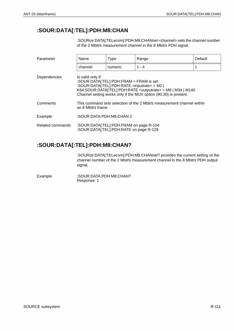
ANT-20 (Mainframe) :SOUR:DATA[:TEL]:PDH:M8:CHAN
:SOUR:DATA[:TEL]:PDH:M8:CHAN
:SOURce:DATA[:TELecom]:PDH:M8:CHANnel <channel> sets the channel number of the 2 Mbit/s measurement channel in the 8 Mbit/s PDH signal.
:SOUR:DATA[:TEL]:PDH:M8:CHAN?
:SOURce:DATA[:TELecom]:PDH:M8:CHANnel? provides the current setting of the channel number of the 2 Mbit/s measurement channel in the 8 Mbit/s PDH output signal.
Parameter Name Type Range Default
channel numeric 1 - 4 1
Dependencies Is valid only if::SOUR:DATA[:TEL]:PDH:FRAM = FRAM is set.:SOUR:DATA[:TEL]:PDH:RATE <inputrate> = M2 | K64:SOUR:DATA[:TEL]:PDH:RATE <outputrate> = M8 | M34 | M140Channel setting works only if the MUX option (90.30) is present.
Comments This command sets selection of the 2 Mbit/s measurement channel within an 8 Mbit/s frame.
Example :SOUR:DATA:PDH:M8:CHAN 2
Related commands :SOUR:DATA[:TEL]:PDH:FRAM on page R-104:SOUR:DATA[:TEL]:PDH:RATE on page R-129
Example :SOUR:DATA:PDH:M8:CHAN?Response: 1
SOURCE subsystem R-111
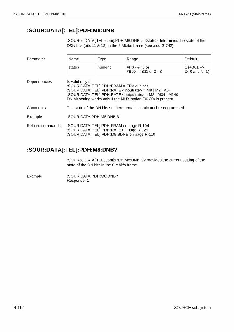
:SOUR:DATA[:TEL]:PDH:M8:DNB ANT-20 (Mainframe)
:SOUR:DATA[:TEL]:PDH:M8:DNB
:SOURce:DATA[:TELecom]:PDH:M8:DNBits <state> determines the state of the D&N bits (bits 11 & 12) in the 8 Mbit/s frame (see also G.742).
:SOUR:DATA[:TEL]:PDH:M8:DNB?
:SOURce:DATA[:TELecom]:PDH:M8:DNBits? provides the current setting of the state of the DN bits in the 8 Mbit/s frame.
Parameter Name Type Range Default
states numeric #H0 - #H3 or#B00 - #B11 or 0 - 3
1 (#B01 =>D=0 and N=1)
Dependencies Is valid only if::SOUR:DATA[:TEL]:PDH:FRAM = FRAM is set.:SOUR:DATA[:TEL]:PDH:RATE <inputrate> = M8 | M2 | K64:SOUR:DATA[:TEL]:PDH:RATE <outputrate> = M8 | M34 | M140DN bit setting works only if the MUX option (90.30) is present.
Comments The state of the DN bits set here remains static until reprogrammed.
Example :SOUR:DATA:PDH:M8:DNB 3
Related commands :SOUR:DATA[:TEL]:PDH:FRAM on page R-104:SOUR:DATA[:TEL]:PDH:RATE on page R-129:SOUR:DATA[:TEL]:PDH:M8:BDNB on page R-110
Example :SOUR:DATA:PDH:M8:DNB?Response: 1
R-112 SOURCE subsystem
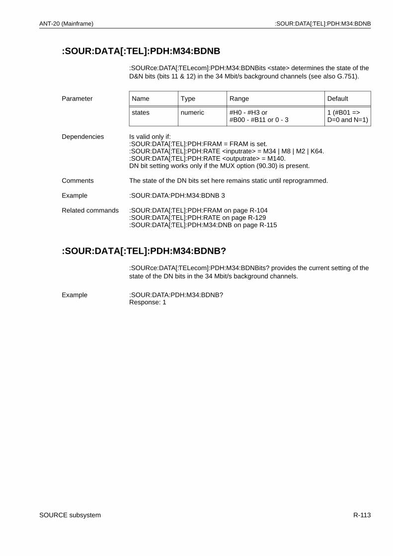
ANT-20 (Mainframe) :SOUR:DATA[:TEL]:PDH:M34:BDNB
:SOUR:DATA[:TEL]:PDH:M34:BDNB
:SOURce:DATA[:TELecom]:PDH:M34:BDNBits <state> determines the state of the D&N bits (bits 11 & 12) in the 34 Mbit/s background channels (see also G.751).
:SOUR:DATA[:TEL]:PDH:M34:BDNB?
:SOURce:DATA[:TELecom]:PDH:M34:BDNBits? provides the current setting of the state of the DN bits in the 34 Mbit/s background channels.
Parameter Name Type Range Default
states numeric #H0 - #H3 or#B00 - #B11 or 0 - 3
1 (#B01 =>D=0 and N=1)
Dependencies Is valid only if::SOUR:DATA[:TEL]:PDH:FRAM = FRAM is set.:SOUR:DATA[:TEL]:PDH:RATE <inputrate> = M34 | M8 | M2 | K64.:SOUR:DATA[:TEL]:PDH:RATE <outputrate> = M140.DN bit setting works only if the MUX option (90.30) is present.
Comments The state of the DN bits set here remains static until reprogrammed.
Example :SOUR:DATA:PDH:M34:BDNB 3
Related commands :SOUR:DATA[:TEL]:PDH:FRAM on page R-104:SOUR:DATA[:TEL]:PDH:RATE on page R-129:SOUR:DATA[:TEL]:PDH:M34:DNB on page R-115
Example :SOUR:DATA:PDH:M34:BDNB?Response: 1
SOURCE subsystem R-113
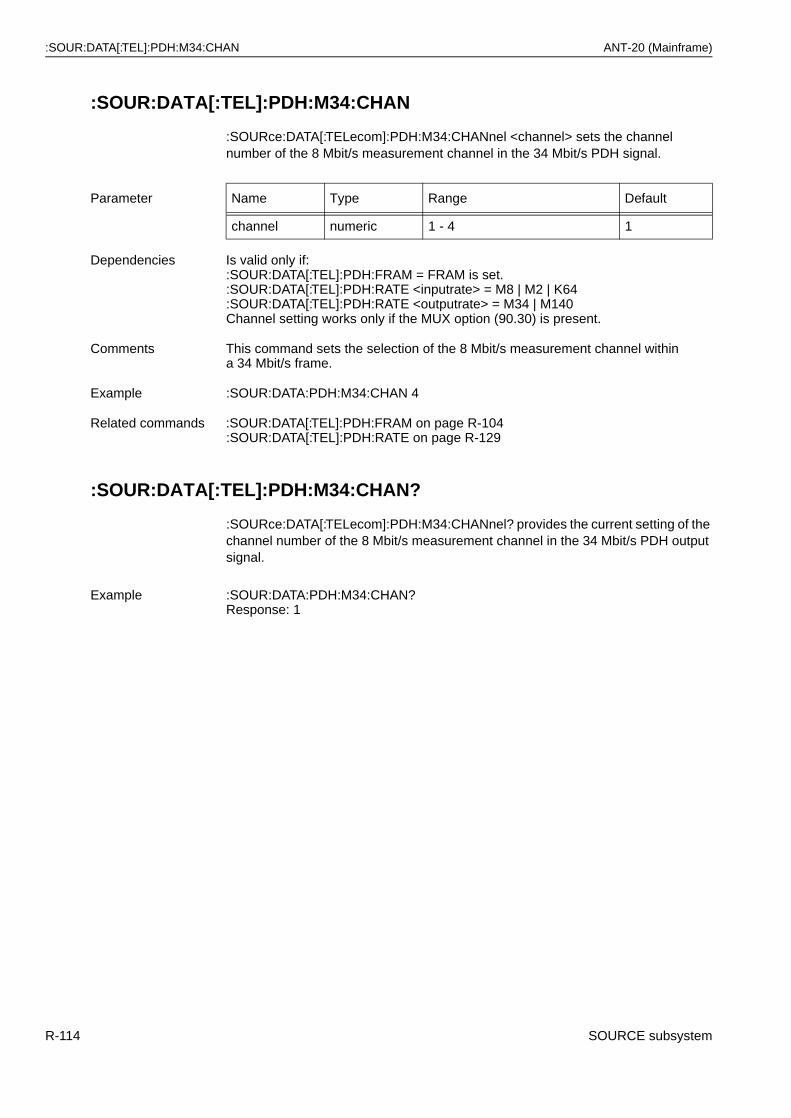
:SOUR:DATA[:TEL]:PDH:M34:CHAN ANT-20 (Mainframe)
:SOUR:DATA[:TEL]:PDH:M34:CHAN
:SOURce:DATA[:TELecom]:PDH:M34:CHANnel <channel> sets the channel number of the 8 Mbit/s measurement channel in the 34 Mbit/s PDH signal.
:SOUR:DATA[:TEL]:PDH:M34:CHAN?
:SOURce:DATA[:TELecom]:PDH:M34:CHANnel? provides the current setting of the channel number of the 8 Mbit/s measurement channel in the 34 Mbit/s PDH output signal.
Parameter Name Type Range Default
channel numeric 1 - 4 1
Dependencies Is valid only if::SOUR:DATA[:TEL]:PDH:FRAM = FRAM is set.:SOUR:DATA[:TEL]:PDH:RATE <inputrate> = M8 | M2 | K64:SOUR:DATA[:TEL]:PDH:RATE <outputrate> = M34 | M140Channel setting works only if the MUX option (90.30) is present.
Comments This command sets the selection of the 8 Mbit/s measurement channel within a 34 Mbit/s frame.
Example :SOUR:DATA:PDH:M34:CHAN 4
Related commands :SOUR:DATA[:TEL]:PDH:FRAM on page R-104:SOUR:DATA[:TEL]:PDH:RATE on page R-129
Example :SOUR:DATA:PDH:M34:CHAN?Response: 1
R-114 SOURCE subsystem
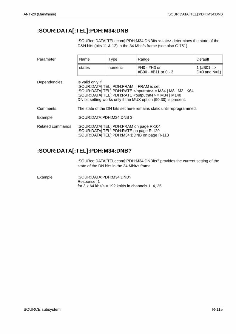
ANT-20 (Mainframe) :SOUR:DATA[:TEL]:PDH:M34:DNB
:SOUR:DATA[:TEL]:PDH:M34:DNB
:SOURce:DATA[:TELecom]:PDH:M34:DNBits <state> determines the state of the D&N bits (bits 11 & 12) in the 34 Mbit/s frame (see also G.751).
:SOUR:DATA[:TEL]:PDH:M34:DNB?
:SOURce:DATA[:TELecom]:PDH:M34:DNBits? provides the current setting of the state of the DN bits in the 34 Mbit/s frame.
Parameter Name Type Range Default
states numeric #H0 - #H3 or#B00 - #B11 or 0 - 3
1 (#B01 =>D=0 and N=1)
Dependencies Is valid only if::SOUR:DATA[:TEL]:PDH:FRAM = FRAM is set.:SOUR:DATA[:TEL]:PDH:RATE <inputrate> = M34 | M8 | M2 | K64:SOUR:DATA[:TEL]:PDH:RATE <outputrate> = M34 | M140DN bit setting works only if the MUX option (90.30) is present.
Comments The state of the DN bits set here remains static until reprogrammed.
Example :SOUR:DATA:PDH:M34:DNB 3
Related commands :SOUR:DATA[:TEL]:PDH:FRAM on page R-104:SOUR:DATA[:TEL]:PDH:RATE on page R-129:SOUR:DATA[:TEL]:PDH:M34:BDNB on page R-113
Example :SOUR:DATA:PDH:M34:DNB?Response: 1for 3 x 64 kbit/s = 192 kbit/s in channels 1, 4, 25
SOURCE subsystem R-115
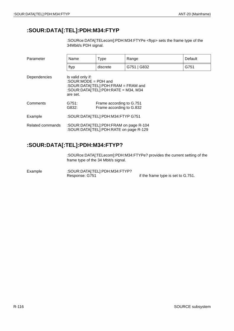
:SOUR:DATA[:TEL]:PDH:M34:FTYP ANT-20 (Mainframe)
:SOUR:DATA[:TEL]:PDH:M34:FTYP
:SOURce:DATA[:TELecom]:PDH:M34:FTYPe <ftyp> sets the frame type of the 34Mbit/s PDH signal.
:SOUR:DATA[:TEL]:PDH:M34:FTYP?
:SOURce:DATA[:TELecom]:PDH:M34:FTYPe? provides the current setting of the frame type of the 34 Mbit/s signal.
Parameter Name Type Range Default
ftyp discrete G751 | G832 G751
Dependencies Is valid only if::SOUR:MODE = PDH and :SOUR:DATA[:TEL]:PDH:FRAM = FRAM and:SOUR:DATA[:TEL]:PDH:RATE = M34, M34are set.
Comments G751:G832:
Frame according to G.751Frame according to G.832
Example :SOUR:DATA[:TEL]:PDH:M34:FTYP G751
Related commands :SOUR:DATA[:TEL]:PDH:FRAM on page R-104:SOUR:DATA[:TEL]:PDH:RATE on page R-129
Example :SOUR:DATA[:TEL]:PDH:M34:FTYP?Response: G751 if the frame type is set to G.751.
R-116 SOURCE subsystem
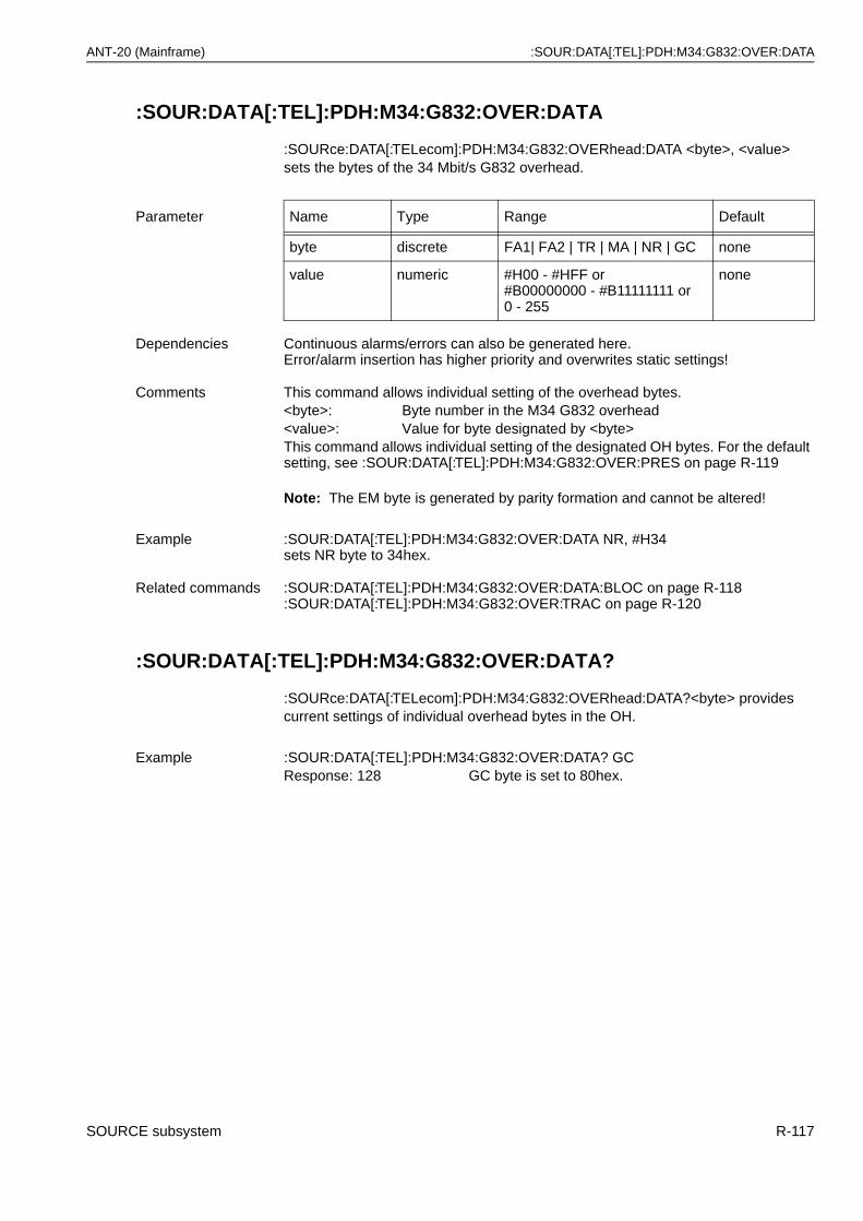
ANT-20 (Mainframe) :SOUR:DATA[:TEL]:PDH:M34:G832:OVER:DATA
:SOUR:DATA[:TEL]:PDH:M34:G832:OVER:DATA
:SOURce:DATA[:TELecom]:PDH:M34:G832:OVERhead:DATA <byte>, <value> sets the bytes of the 34 Mbit/s G832 overhead.
Note: The EM byte is generated by parity formation and cannot be altered!
:SOUR:DATA[:TEL]:PDH:M34:G832:OVER:DATA?
:SOURce:DATA[:TELecom]:PDH:M34:G832:OVERhead:DATA?<byte> provides current settings of individual overhead bytes in the OH.
Parameter Name Type Range Default
byte discrete FA1| FA2 | TR | MA | NR | GC none
value numeric #H00 - #HFF or#B00000000 - #B11111111 or 0 - 255
none
Dependencies Continuous alarms/errors can also be generated here.Error/alarm insertion has higher priority and overwrites static settings!
Comments This command allows individual setting of the overhead bytes.<byte>: Byte number in the M34 G832 overhead<value>: Value for byte designated by <byte>This command allows individual setting of the designated OH bytes. For the default setting, see :SOUR:DATA[:TEL]:PDH:M34:G832:OVER:PRES on page R-119
Example :SOUR:DATA[:TEL]:PDH:M34:G832:OVER:DATA NR, #H34sets NR byte to 34hex.
Related commands :SOUR:DATA[:TEL]:PDH:M34:G832:OVER:DATA:BLOC on page R-118:SOUR:DATA[:TEL]:PDH:M34:G832:OVER:TRAC on page R-120
Example :SOUR:DATA[:TEL]:PDH:M34:G832:OVER:DATA? GCResponse: 128 GC byte is set to 80hex.
SOURCE subsystem R-117
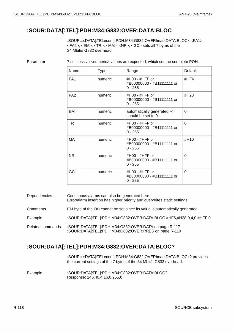
:SOUR:DATA[:TEL]:PDH:M34:G832:OVER:DATA:BLOC ANT-20 (Mainframe)
:SOUR:DATA[:TEL]:PDH:M34:G832:OVER:DATA:BLOC
:SOURce:DATA[:TELecom]:PDH:M34:G832:OVERhead:DATA:BLOCk <FA1>, <FA2>, <EM>, <TR>, <MA>, <NR>, <GC> sets all 7 bytes of the34 Mbit/s G832 overhead.
:SOUR:DATA[:TEL]:PDH:M34:G832:OVER:DATA:BLOC?
:SOURce:DATA[:TELecom]:PDH:M34:G832:OVERhead:DATA:BLOCk? provides the current settings of the 7 bytes of the 34 Mbit/s G832 overhead.
Parameter 7 successive <numeric> values are expected, which set the complete POH.
Name Type Range Default
FA1 numeric #H00 - #HFF or#B00000000 - #B11111111 or 0 - 255
#HF6
FA2 numeric #H00 - #HFF or#B00000000 - #B11111111 or0 - 255
#H28
EM numeric automatically generated --> should be set to 0
0
TR numeric #H00 - #HFF or#B00000000 - #B11111111 or 0 - 255
0
MA numeric #H00 - #HFF or#B00000000 - #B11111111 or 0 - 255
#H10
NR numeric #H00 - #HFF or#B00000000 - #B11111111 or 0 - 255
0
GC numeric #H00 - #HFF or#B00000000 - #B11111111 or 0 - 255
0
Dependencies Continuous alarms can also be generated here. Error/alarm insertion has higher priority and overwrites static settings!
Comments EM byte of the OH cannot be set since its value is automatically generated.
Example :SOUR:DATA[:TEL]:PDH:M34:G832:OVER:DATA:BLOC #HF6,#H28,0,4,0,#HFF,0
Related commands :SOUR:DATA[:TEL]:PDH:M34:G832:OVER:DATA on page R-117:SOUR:DATA[:TEL]:PDH:M34:G832:OVER:PRES on page R-119
Example :SOUR:DATA[:TEL]:PDH:M34:G832:OVER:DATA:BLOC?Response: 246,40,4,16,0,255,0
R-118 SOURCE subsystem
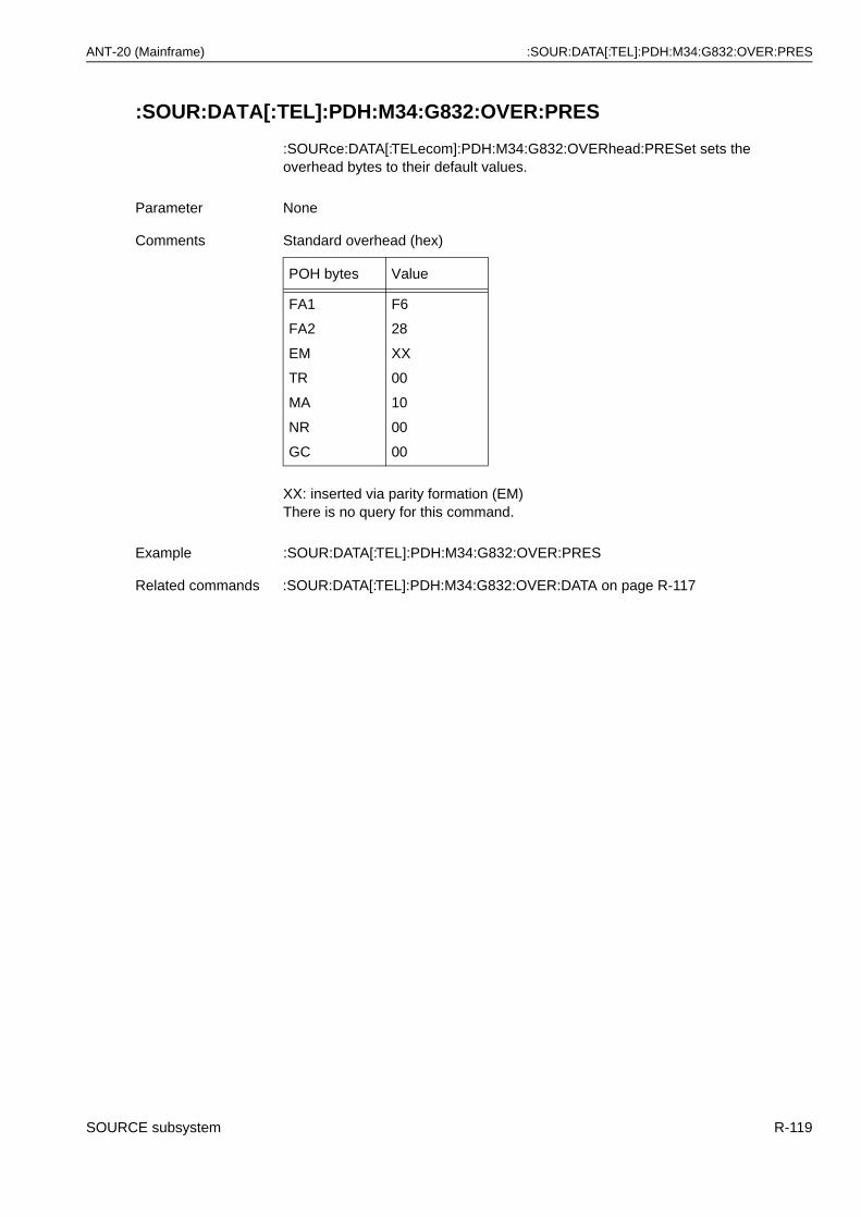
ANT-20 (Mainframe) :SOUR:DATA[:TEL]:PDH:M34:G832:OVER:PRES
:SOUR:DATA[:TEL]:PDH:M34:G832:OVER:PRES
:SOURce:DATA[:TELecom]:PDH:M34:G832:OVERhead:PRESet sets the overhead bytes to their default values.
XX: inserted via parity formation (EM)There is no query for this command.
Parameter None
Comments Standard overhead (hex)
POH bytes Value
FA1
FA2
EM
TR
MA
NR
GC
F6
28
XX
00
10
00
00
Example :SOUR:DATA[:TEL]:PDH:M34:G832:OVER:PRES
Related commands :SOUR:DATA[:TEL]:PDH:M34:G832:OVER:DATA on page R-117
SOURCE subsystem R-119
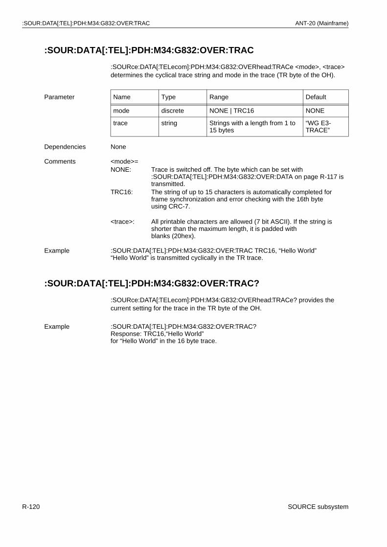
:SOUR:DATA[:TEL]:PDH:M34:G832:OVER:TRAC ANT-20 (Mainframe)
:SOUR:DATA[:TEL]:PDH:M34:G832:OVER:TRAC
:SOURce:DATA[:TELecom]:PDH:M34:G832:OVERhead:TRACe <mode>, <trace> determines the cyclical trace string and mode in the trace (TR byte of the OH).
:SOUR:DATA[:TEL]:PDH:M34:G832:OVER:TRAC?
:SOURce:DATA[:TELecom]:PDH:M34:G832:OVERhead:TRACe? provides the current setting for the trace in the TR byte of the OH.
Parameter Name Type Range Default
mode discrete NONE | TRC16 NONE
trace string Strings with a length from 1 to 15 bytes
“WG E3-TRACE”
Dependencies None
Comments <mode>=NONE: Trace is switched off. The byte which can be set with
:SOUR:DATA[:TEL]:PDH:M34:G832:OVER:DATA on page R-117 is transmitted.
TRC16: The string of up to 15 characters is automatically completed forframe synchronization and error checking with the 16th byteusing CRC-7.
<trace>: All printable characters are allowed (7 bit ASCII). If the string isshorter than the maximum length, it is padded withblanks (20hex).
Example :SOUR:DATA[:TEL]:PDH:M34:G832:OVER:TRAC TRC16, “Hello World”“Hello World” is transmitted cyclically in the TR trace.
Example :SOUR:DATA[:TEL]:PDH:M34:G832:OVER:TRAC?Response: TRC16,“Hello World”for “Hello World” in the 16 byte trace.
R-120 SOURCE subsystem
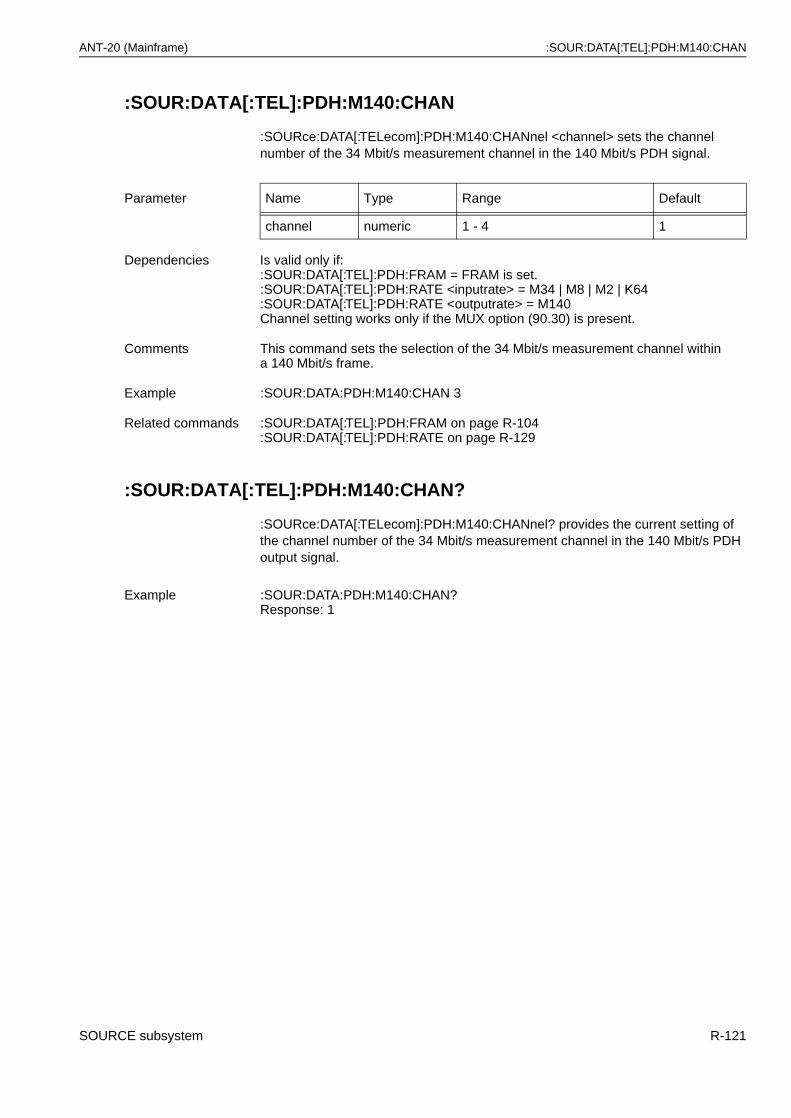
ANT-20 (Mainframe) :SOUR:DATA[:TEL]:PDH:M140:CHAN
:SOUR:DATA[:TEL]:PDH:M140:CHAN
:SOURce:DATA[:TELecom]:PDH:M140:CHANnel <channel> sets the channel number of the 34 Mbit/s measurement channel in the 140 Mbit/s PDH signal.
:SOUR:DATA[:TEL]:PDH:M140:CHAN?
:SOURce:DATA[:TELecom]:PDH:M140:CHANnel? provides the current setting of the channel number of the 34 Mbit/s measurement channel in the 140 Mbit/s PDH output signal.
Parameter Name Type Range Default
channel numeric 1 - 4 1
Dependencies Is valid only if::SOUR:DATA[:TEL]:PDH:FRAM = FRAM is set.:SOUR:DATA[:TEL]:PDH:RATE <inputrate> = M34 | M8 | M2 | K64:SOUR:DATA[:TEL]:PDH:RATE <outputrate> = M140Channel setting works only if the MUX option (90.30) is present.
Comments This command sets the selection of the 34 Mbit/s measurement channel within a 140 Mbit/s frame.
Example :SOUR:DATA:PDH:M140:CHAN 3
Related commands :SOUR:DATA[:TEL]:PDH:FRAM on page R-104:SOUR:DATA[:TEL]:PDH:RATE on page R-129
Example :SOUR:DATA:PDH:M140:CHAN?Response: 1
SOURCE subsystem R-121
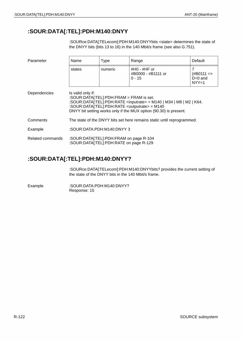
:SOUR:DATA[:TEL]:PDH:M140:DNYY ANT-20 (Mainframe)
:SOUR:DATA[:TEL]:PDH:M140:DNYY
:SOURce:DATA[:TELecom]:PDH:M140:DNYYbits <state> determines the state of the DNYY bits (bits 13 to 16) in the 140 Mbit/s frame (see also G.751).
:SOUR:DATA[:TEL]:PDH:M140:DNYY?
:SOURce:DATA[:TELecom]:PDH:M140:DNYYbits? provides the current setting of the state of the DNYY bits in the 140 Mbit/s frame.
Parameter Name Type Range Default
states numeric #H0 - #HF or#B0000 - #B1111 or0 - 15
7(#B0111 =>D=0 andNYY=1
Dependencies Is valid only if::SOUR:DATA[:TEL]:PDH:FRAM = FRAM is set.:SOUR:DATA[:TEL]:PDH:RATE <inputrate> = M140 | M34 | M8 | M2 | K64.:SOUR:DATA[:TEL]:PDH:RATE <outputrate> = M140DNYY bit setting works only if the MUX option (90.30) is present.
Comments The state of the DNYY bits set here remains static until reprogrammed.
Example :SOUR:DATA:PDH:M140:DNYY 3
Related commands :SOUR:DATA[:TEL]:PDH:FRAM on page R-104:SOUR:DATA[:TEL]:PDH:RATE on page R-129
Example :SOUR:DATA:PDH:M140:DNYY?Response: 15
R-122 SOURCE subsystem
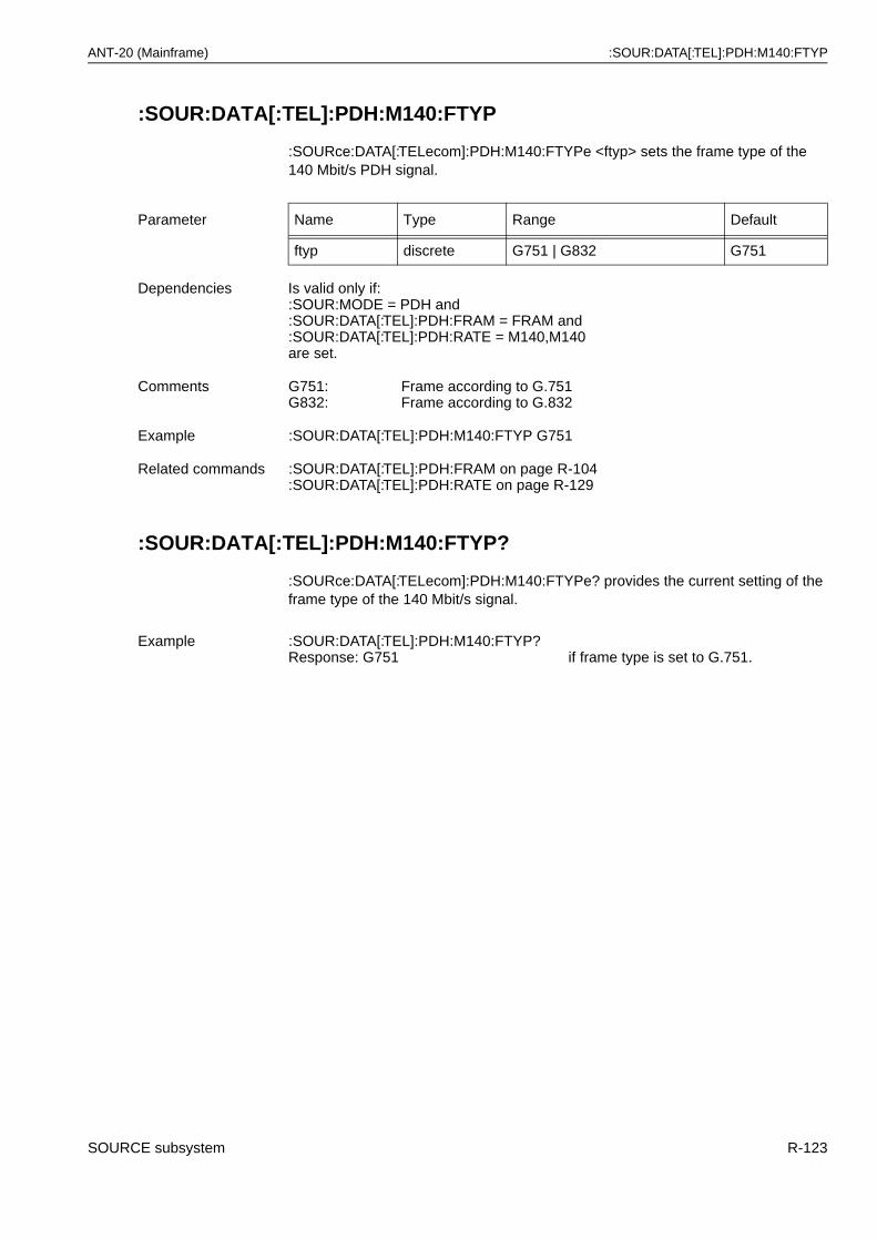
ANT-20 (Mainframe) :SOUR:DATA[:TEL]:PDH:M140:FTYP
:SOUR:DATA[:TEL]:PDH:M140:FTYP
:SOURce:DATA[:TELecom]:PDH:M140:FTYPe <ftyp> sets the frame type of the 140 Mbit/s PDH signal.
:SOUR:DATA[:TEL]:PDH:M140:FTYP?
:SOURce:DATA[:TELecom]:PDH:M140:FTYPe? provides the current setting of the frame type of the 140 Mbit/s signal.
Parameter Name Type Range Default
ftyp discrete G751 | G832 G751
Dependencies Is valid only if::SOUR:MODE = PDH and :SOUR:DATA[:TEL]:PDH:FRAM = FRAM and:SOUR:DATA[:TEL]:PDH:RATE = M140,M140are set.
Comments G751:G832:
Frame according to G.751Frame according to G.832
Example :SOUR:DATA[:TEL]:PDH:M140:FTYP G751
Related commands :SOUR:DATA[:TEL]:PDH:FRAM on page R-104:SOUR:DATA[:TEL]:PDH:RATE on page R-129
Example :SOUR:DATA[:TEL]:PDH:M140:FTYP?Response: G751 if frame type is set to G.751.
SOURCE subsystem R-123
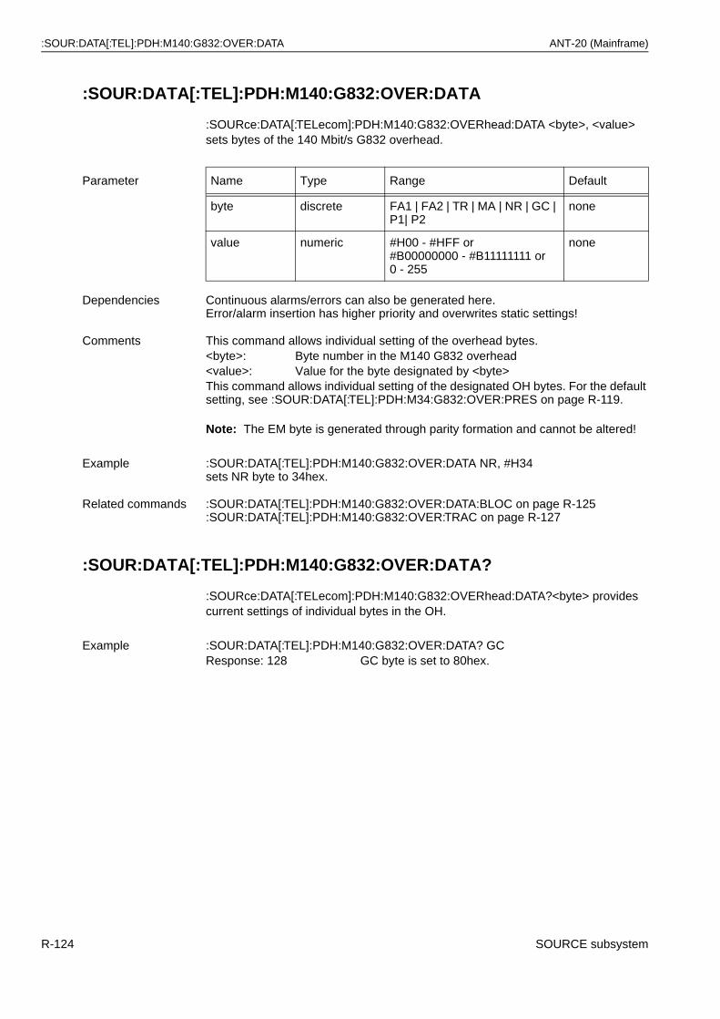
:SOUR:DATA[:TEL]:PDH:M140:G832:OVER:DATA ANT-20 (Mainframe)
:SOUR:DATA[:TEL]:PDH:M140:G832:OVER:DATA
:SOURce:DATA[:TELecom]:PDH:M140:G832:OVERhead:DATA <byte>, <value> sets bytes of the 140 Mbit/s G832 overhead.
Note: The EM byte is generated through parity formation and cannot be altered!
:SOUR:DATA[:TEL]:PDH:M140:G832:OVER:DATA?
:SOURce:DATA[:TELecom]:PDH:M140:G832:OVERhead:DATA?<byte> provides current settings of individual bytes in the OH.
Parameter Name Type Range Default
byte discrete FA1 | FA2 | TR | MA | NR | GC | P1| P2
none
value numeric #H00 - #HFF or#B00000000 - #B11111111 or 0 - 255
none
Dependencies Continuous alarms/errors can also be generated here.Error/alarm insertion has higher priority and overwrites static settings!
Comments This command allows individual setting of the overhead bytes.<byte>: Byte number in the M140 G832 overhead<value>: Value for the byte designated by <byte>This command allows individual setting of the designated OH bytes. For the default setting, see :SOUR:DATA[:TEL]:PDH:M34:G832:OVER:PRES on page R-119.
Example :SOUR:DATA[:TEL]:PDH:M140:G832:OVER:DATA NR, #H34sets NR byte to 34hex.
Related commands :SOUR:DATA[:TEL]:PDH:M140:G832:OVER:DATA:BLOC on page R-125:SOUR:DATA[:TEL]:PDH:M140:G832:OVER:TRAC on page R-127
Example :SOUR:DATA[:TEL]:PDH:M140:G832:OVER:DATA? GCResponse: 128 GC byte is set to 80hex.
R-124 SOURCE subsystem
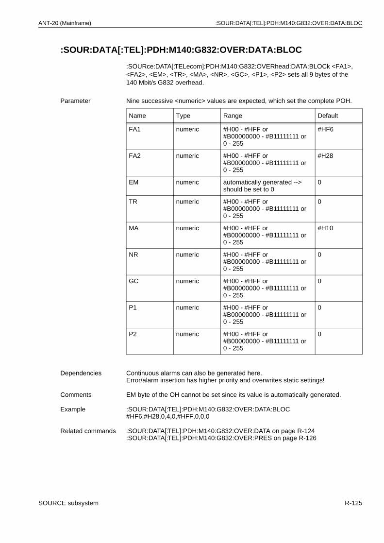
ANT-20 (Mainframe) :SOUR:DATA[:TEL]:PDH:M140:G832:OVER:DATA:BLOC
:SOUR:DATA[:TEL]:PDH:M140:G832:OVER:DATA:BLOC
:SOURce:DATA[:TELecom]:PDH:M140:G832:OVERhead:DATA:BLOCk <FA1>, <FA2>, <EM>, <TR>, <MA>, <NR>, <GC>, <P1>, <P2> sets all 9 bytes of the 140 Mbit/s G832 overhead.
Parameter Nine successive <numeric> values are expected, which set the complete POH.
Name Type Range Default
FA1 numeric #H00 - #HFF or#B00000000 - #B11111111 or0 - 255
#HF6
FA2 numeric #H00 - #HFF or#B00000000 - #B11111111 or 0 - 255
#H28
EM numeric automatically generated --> should be set to 0
0
TR numeric #H00 - #HFF or#B00000000 - #B11111111 or 0 - 255
0
MA numeric #H00 - #HFF or#B00000000 - #B11111111 or 0 - 255
#H10
NR numeric #H00 - #HFF or#B00000000 - #B11111111 or 0 - 255
0
GC numeric #H00 - #HFF or#B00000000 - #B11111111 or 0 - 255
0
P1 numeric #H00 - #HFF or#B00000000 - #B11111111 or 0 - 255
0
P2 numeric #H00 - #HFF or#B00000000 - #B11111111 or 0 - 255
0
Dependencies Continuous alarms can also be generated here. Error/alarm insertion has higher priority and overwrites static settings!
Comments EM byte of the OH cannot be set since its value is automatically generated.
Example :SOUR:DATA[:TEL]:PDH:M140:G832:OVER:DATA:BLOC #HF6,#H28,0,4,0,#HFF,0,0,0
Related commands :SOUR:DATA[:TEL]:PDH:M140:G832:OVER:DATA on page R-124:SOUR:DATA[:TEL]:PDH:M140:G832:OVER:PRES on page R-126
SOURCE subsystem R-125
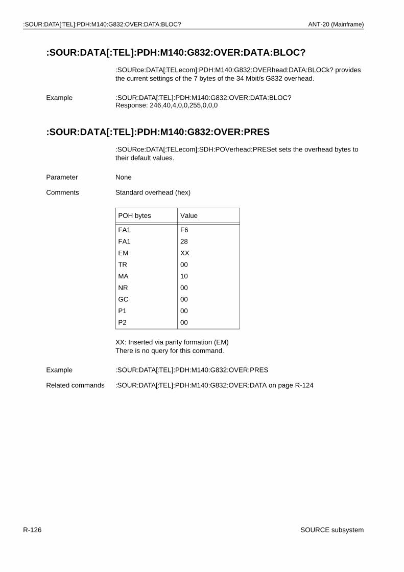
:SOUR:DATA[:TEL]:PDH:M140:G832:OVER:DATA:BLOC? ANT-20 (Mainframe)
:SOUR:DATA[:TEL]:PDH:M140:G832:OVER:DATA:BLOC?
:SOURce:DATA[:TELecom]:PDH:M140:G832:OVERhead:DATA:BLOCk? provides the current settings of the 7 bytes of the 34 Mbit/s G832 overhead.
:SOUR:DATA[:TEL]:PDH:M140:G832:OVER:PRES
:SOURce:DATA[:TELecom]:SDH:POVerhead:PRESet sets the overhead bytes to their default values.
XX: Inserted via parity formation (EM)There is no query for this command.
Example :SOUR:DATA[:TEL]:PDH:M140:G832:OVER:DATA:BLOC?Response: 246,40,4,0,0,255,0,0,0
Parameter None
Comments Standard overhead (hex)
POH bytes Value
FA1
FA1
EM
TR
MA
NR
GC
P1
P2
F6
28
XX
00
10
00
00
00
00
Example :SOUR:DATA[:TEL]:PDH:M140:G832:OVER:PRES
Related commands :SOUR:DATA[:TEL]:PDH:M140:G832:OVER:DATA on page R-124
R-126 SOURCE subsystem
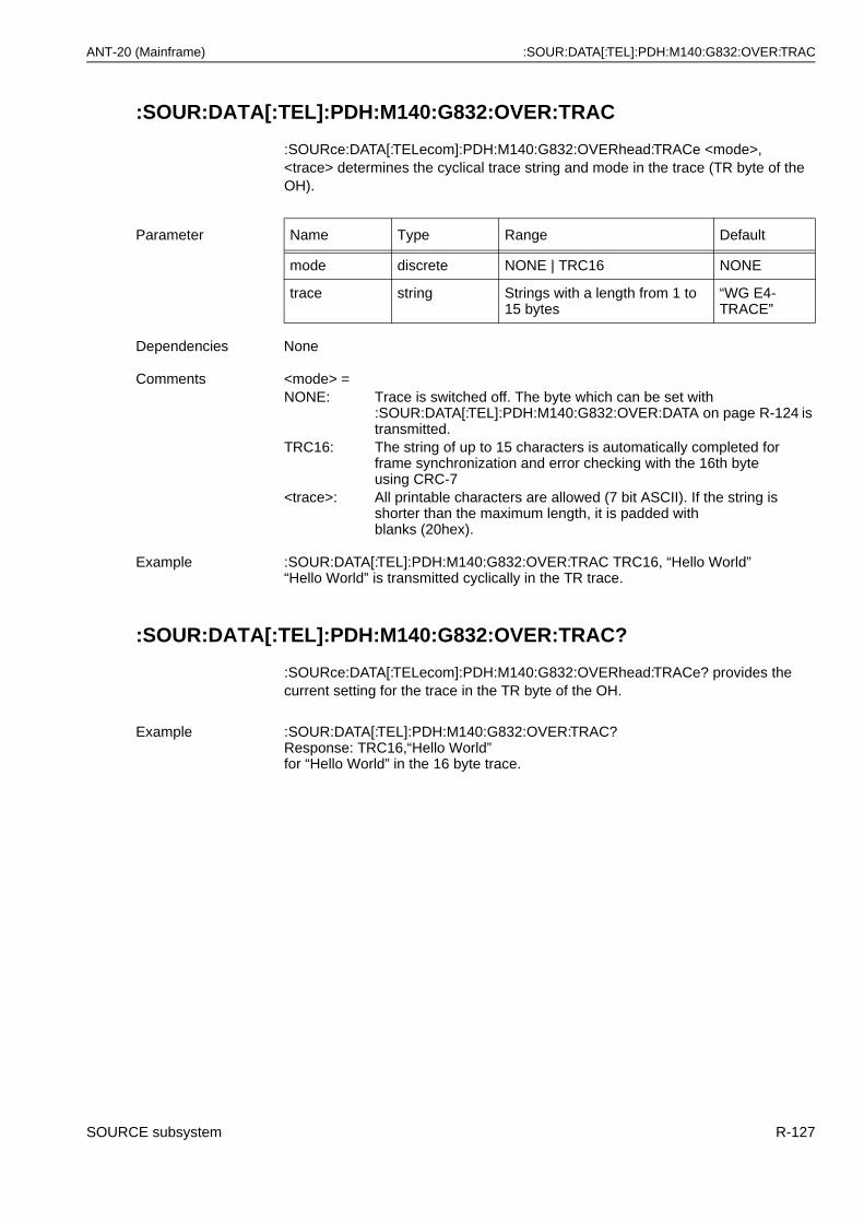
ANT-20 (Mainframe) :SOUR:DATA[:TEL]:PDH:M140:G832:OVER:TRAC
:SOUR:DATA[:TEL]:PDH:M140:G832:OVER:TRAC
:SOURce:DATA[:TELecom]:PDH:M140:G832:OVERhead:TRACe <mode>, <trace> determines the cyclical trace string and mode in the trace (TR byte of the OH).
:SOUR:DATA[:TEL]:PDH:M140:G832:OVER:TRAC?
:SOURce:DATA[:TELecom]:PDH:M140:G832:OVERhead:TRACe? provides the current setting for the trace in the TR byte of the OH.
Parameter Name Type Range Default
mode discrete NONE | TRC16 NONE
trace string Strings with a length from 1 to 15 bytes
“WG E4-TRACE”
Dependencies None
Comments <mode> =NONE: Trace is switched off. The byte which can be set with
:SOUR:DATA[:TEL]:PDH:M140:G832:OVER:DATA on page R-124 is transmitted.
TRC16: The string of up to 15 characters is automatically completed forframe synchronization and error checking with the 16th byte using CRC-7
<trace>: All printable characters are allowed (7 bit ASCII). If the string is shorter than the maximum length, it is padded withblanks (20hex).
Example :SOUR:DATA[:TEL]:PDH:M140:G832:OVER:TRAC TRC16, “Hello World”“Hello World” is transmitted cyclically in the TR trace.
Example :SOUR:DATA[:TEL]:PDH:M140:G832:OVER:TRAC?Response: TRC16,“Hello World”for “Hello World” in the 16 byte trace.
SOURCE subsystem R-127
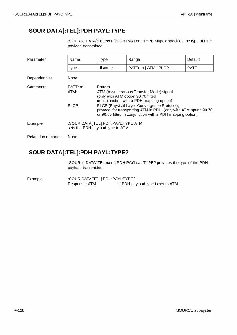
:SOUR:DATA[:TEL]:PDH:PAYL:TYPE ANT-20 (Mainframe)
:SOUR:DATA[:TEL]:PDH:PAYL:TYPE
:SOURce:DATA[:TELecom]:PDH:PAYLoad:TYPE <type> specifies the type of PDH payload transmitted.
:SOUR:DATA[:TEL]:PDH:PAYL:TYPE?
:SOURce:DATA[:TELecom]:PDH:PAYLoad:TYPE? provides the type of the PDH payload transmitted.
Parameter Name Type Range Default
type discrete PATTern | ATM | PLCP PATT
Dependencies None
Comments PATTern: PatternATM: ATM (Asynchronous Transfer Mode) signal
(only with ATM option 90.70 fitted in conjunction with a PDH mapping option)
PLCP: PLCP (Physical Layer Convergence Protocol), protocol for transporting ATM in PDH, (only with ATM option 90.70 or 90.80 fitted in conjunction with a PDH mapping option)
Example :SOUR:DATA[:TEL]:PDH:PAYL:TYPE ATM sets the PDH payload type to ATM.
Related commands None
Example :SOUR:DATA[:TEL]:PDH:PAYL:TYPE?Response: ATM if PDH payload type is set to ATM.
R-128 SOURCE subsystem
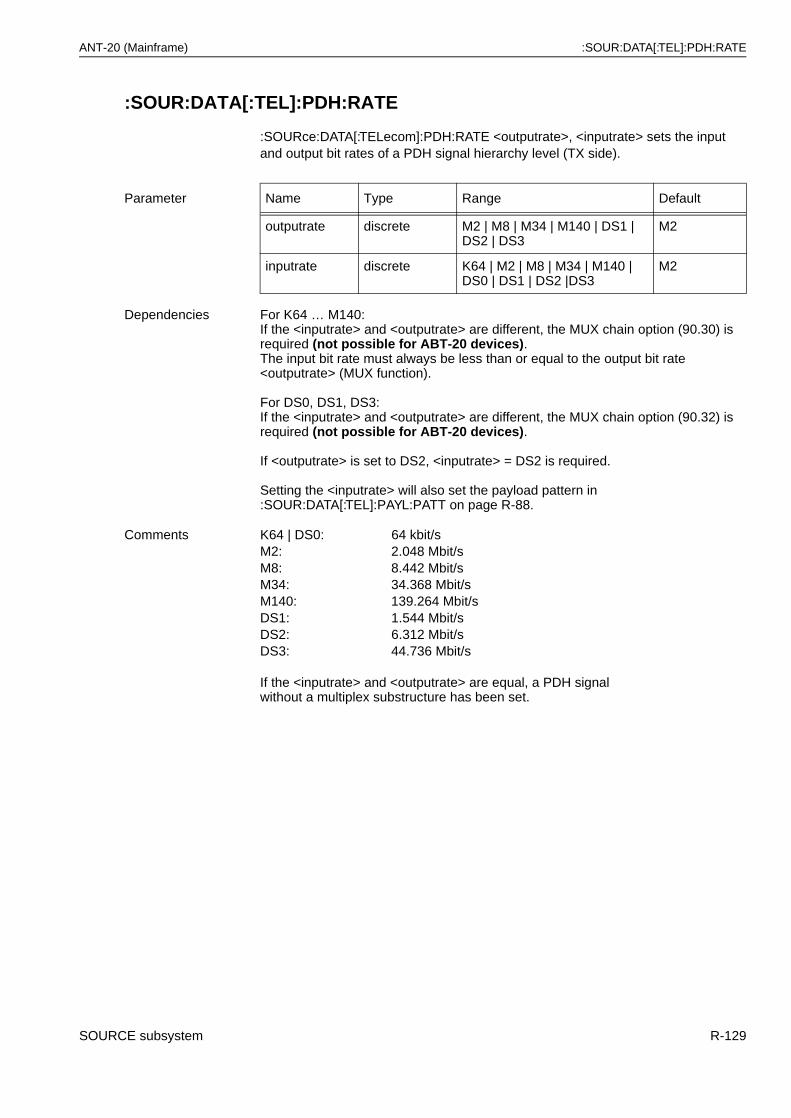
ANT-20 (Mainframe) :SOUR:DATA[:TEL]:PDH:RATE
:SOUR:DATA[:TEL]:PDH:RATE
:SOURce:DATA[:TELecom]:PDH:RATE <outputrate>, <inputrate> sets the input and output bit rates of a PDH signal hierarchy level (TX side).
Parameter Name Type Range Default
outputrate discrete M2 | M8 | M34 | M140 | DS1 | DS2 | DS3
M2
inputrate discrete K64 | M2 | M8 | M34 | M140 | DS0 | DS1 | DS2 |DS3
M2
Dependencies For K64 … M140:If the <inputrate> and <outputrate> are different, the MUX chain option (90.30) is required (not possible for ABT-20 devices).The input bit rate must always be less than or equal to the output bit rate <outputrate> (MUX function).
For DS0, DS1, DS3:If the <inputrate> and <outputrate> are different, the MUX chain option (90.32) is required (not possible for ABT-20 devices).
If <outputrate> is set to DS2, <inputrate> = DS2 is required.
Setting the <inputrate> will also set the payload pattern in :SOUR:DATA[:TEL]:PAYL:PATT on page R-88.
Comments K64 | DS0: 64 kbit/sM2: 2.048 Mbit/sM8: 8.442 Mbit/sM34: 34.368 Mbit/sM140: 139.264 Mbit/sDS1: 1.544 Mbit/sDS2: 6.312 Mbit/sDS3: 44.736 Mbit/s
If the <inputrate> and <outputrate> are equal, a PDH signalwithout a multiplex substructure has been set.
SOURCE subsystem R-129
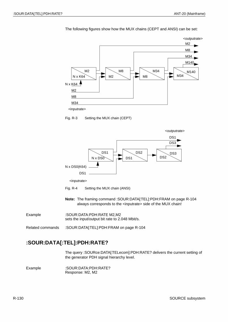
:SOUR:DATA[:TEL]:PDH:RATE? ANT-20 (Mainframe)
The following figures show how the MUX chains (CEPT and ANSI) can be set:
Fig. R-3 Setting the MUX chain (CEPT)
Fig. R-4 Setting the MUX chain (ANSI)
Note: The framing command :SOUR:DATA[:TEL]:PDH:FRAM on page R-104 always corresponds to the <inputrate> side of the MUX chain!
:SOUR:DATA[:TEL]:PDH:RATE?
The query :SOURce:DATA[:TELecom]:PDH:RATE? delivers the current setting of the generator PDH signal hierarchy level.
Example :SOUR:DATA:PDH:RATE M2,M2sets the input/output bit rate to 2.048 Mbit/s.
Related commands :SOUR:DATA[:TEL]:PDH:FRAM on page R-104
Example :SOUR:DATA:PDH:RATE?Response: M2, M2
M140M34
M34
M8
M8
M2
M2
N x K64
M140
M2
M8
M34
<outputrate>
M34
N x K64
M2
M8
<inputrate>
DS3DS2
DS2
DS1
DS1
N x DS0
DS3
DS1
DS1
N x DS0(K64)
<inputrate>
<outputrate>
R-130 SOURCE subsystem
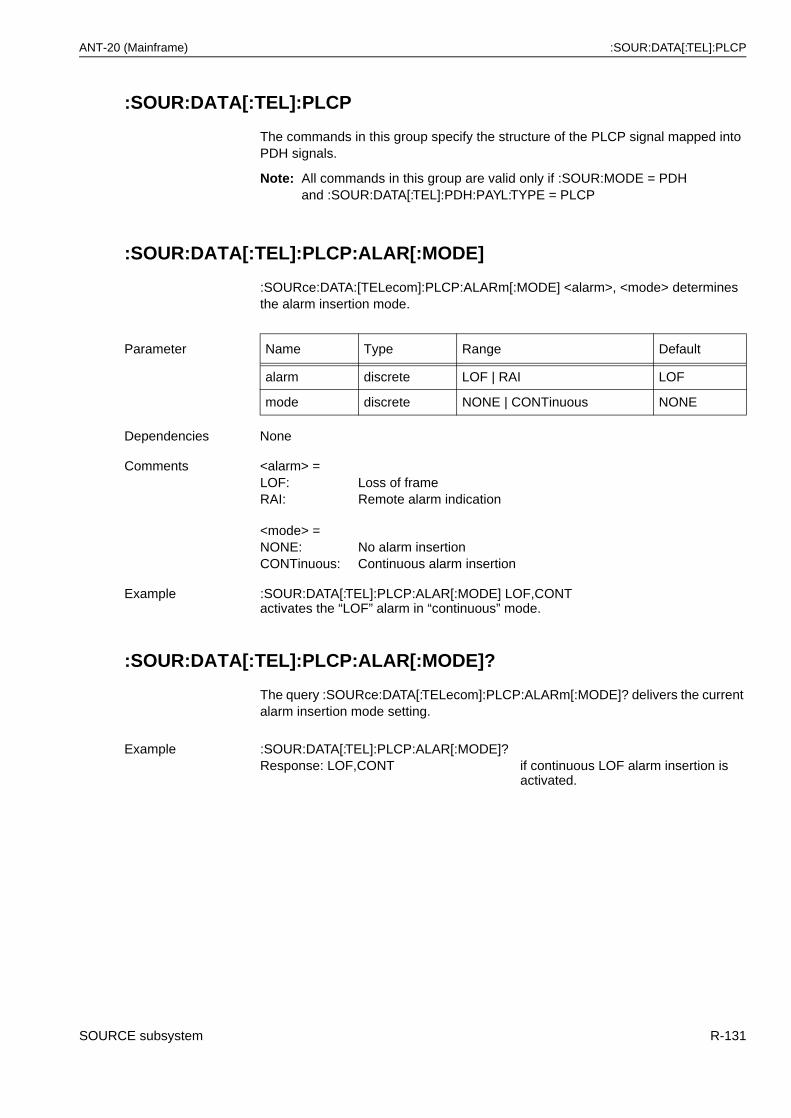
ANT-20 (Mainframe) :SOUR:DATA[:TEL]:PLCP
:SOUR:DATA[:TEL]:PLCP
The commands in this group specify the structure of the PLCP signal mapped into PDH signals.
Note: All commands in this group are valid only if :SOUR:MODE = PDHand :SOUR:DATA[:TEL]:PDH:PAYL:TYPE = PLCP
:SOUR:DATA[:TEL]:PLCP:ALAR[:MODE]
:SOURce:DATA:[TELecom]:PLCP:ALARm[:MODE] <alarm>, <mode> determines the alarm insertion mode.
:SOUR:DATA[:TEL]:PLCP:ALAR[:MODE]?
The query :SOURce:DATA[:TELecom]:PLCP:ALARm[:MODE]? delivers the current alarm insertion mode setting.
Parameter Name Type Range Default
alarm discrete LOF | RAI LOF
mode discrete NONE | CONTinuous NONE
Dependencies None
Comments <alarm> =LOF: Loss of frameRAI: Remote alarm indication
<mode> =NONE: No alarm insertionCONTinuous: Continuous alarm insertion
Example :SOUR:DATA[:TEL]:PLCP:ALAR[:MODE] LOF,CONT activates the “LOF” alarm in “continuous” mode.
Example :SOUR:DATA[:TEL]:PLCP:ALAR[:MODE]?Response: LOF,CONT if continuous LOF alarm insertion is
activated.
SOURCE subsystem R-131
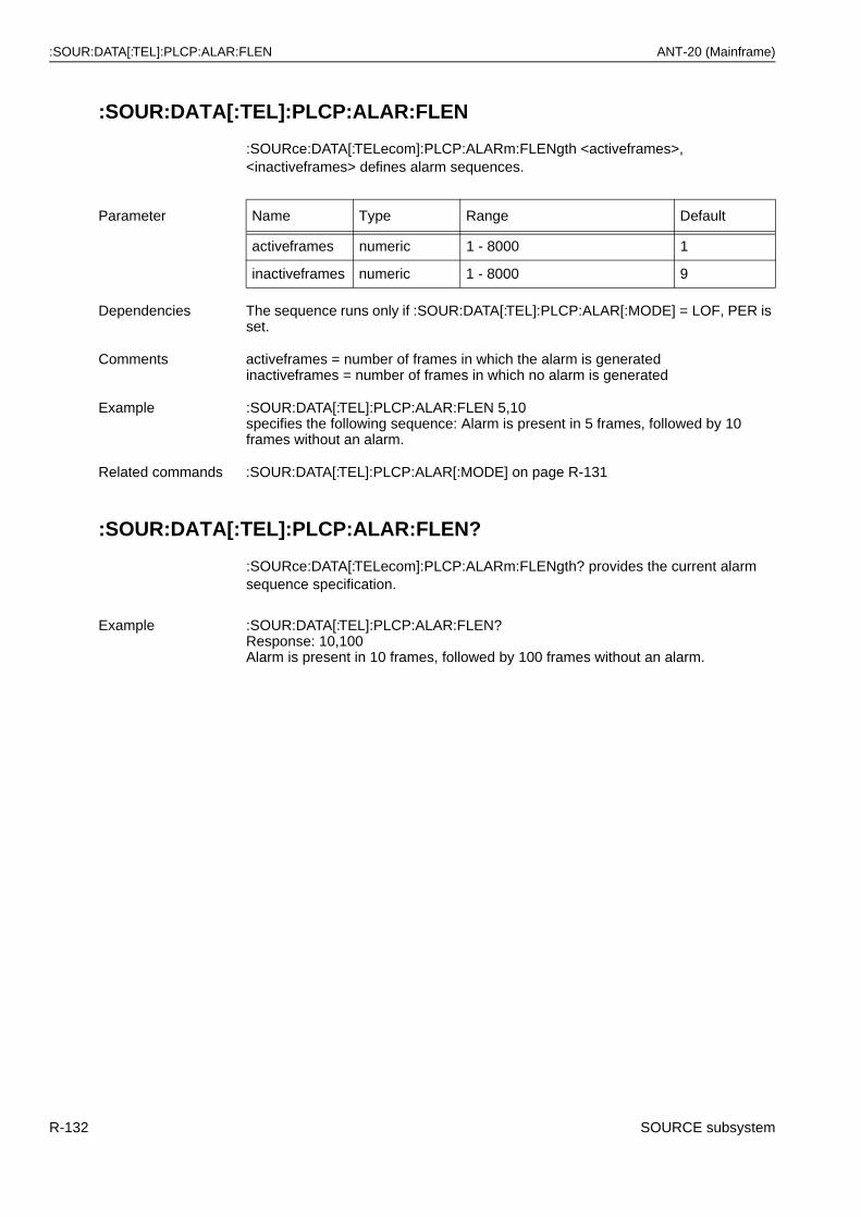
:SOUR:DATA[:TEL]:PLCP:ALAR:FLEN ANT-20 (Mainframe)
:SOUR:DATA[:TEL]:PLCP:ALAR:FLEN
:SOURce:DATA[:TELecom]:PLCP:ALARm:FLENgth <activeframes>, <inactiveframes> defines alarm sequences.
:SOUR:DATA[:TEL]:PLCP:ALAR:FLEN?
:SOURce:DATA[:TELecom]:PLCP:ALARm:FLENgth? provides the current alarm sequence specification.
Parameter Name Type Range Default
activeframes numeric 1 - 8000 1
inactiveframes numeric 1 - 8000 9
Dependencies The sequence runs only if :SOUR:DATA[:TEL]:PLCP:ALAR[:MODE] = LOF, PER is set.
Comments activeframes = number of frames in which the alarm is generatedinactiveframes = number of frames in which no alarm is generated
Example :SOUR:DATA[:TEL]:PLCP:ALAR:FLEN 5,10specifies the following sequence: Alarm is present in 5 frames, followed by 10 frames without an alarm.
Related commands :SOUR:DATA[:TEL]:PLCP:ALAR[:MODE] on page R-131
Example :SOUR:DATA[:TEL]:PLCP:ALAR:FLEN?Response: 10,100Alarm is present in 10 frames, followed by 100 frames without an alarm.
R-132 SOURCE subsystem
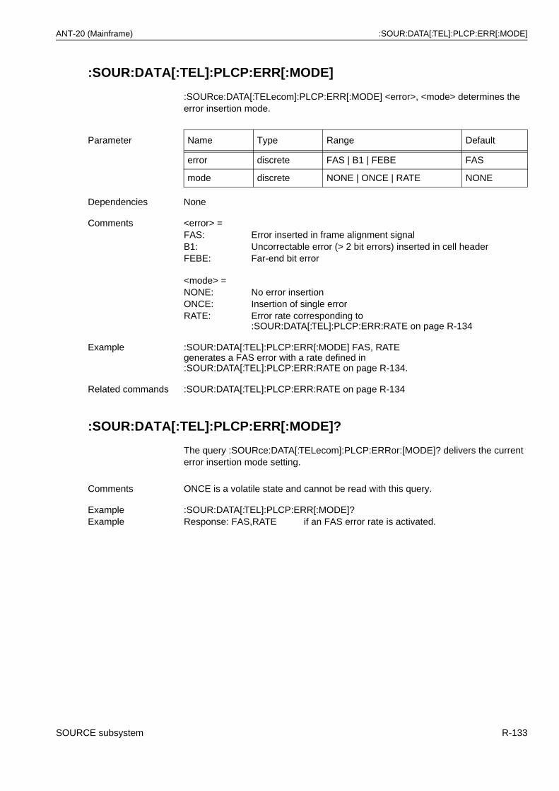
ANT-20 (Mainframe) :SOUR:DATA[:TEL]:PLCP:ERR[:MODE]
:SOUR:DATA[:TEL]:PLCP:ERR[:MODE]
:SOURce:DATA[:TELecom]:PLCP:ERR[:MODE] <error>, <mode> determines the error insertion mode.
:SOUR:DATA[:TEL]:PLCP:ERR[:MODE]?
The query :SOURce:DATA[:TELecom]:PLCP:ERRor:[MODE]? delivers the current error insertion mode setting.
Parameter Name Type Range Default
error discrete FAS | B1 | FEBE FAS
mode discrete NONE | ONCE | RATE NONE
Dependencies None
Comments <error> =FAS: Error inserted in frame alignment signalB1: Uncorrectable error (> 2 bit errors) inserted in cell headerFEBE: Far-end bit error
<mode> =NONE: No error insertionONCE: Insertion of single errorRATE: Error rate corresponding to
:SOUR:DATA[:TEL]:PLCP:ERR:RATE on page R-134
Example :SOUR:DATA[:TEL]:PLCP:ERR[:MODE] FAS, RATEgenerates a FAS error with a rate defined in :SOUR:DATA[:TEL]:PLCP:ERR:RATE on page R-134.
Related commands :SOUR:DATA[:TEL]:PLCP:ERR:RATE on page R-134
Comments ONCE is a volatile state and cannot be read with this query.
Example :SOUR:DATA[:TEL]:PLCP:ERR[:MODE]?Example Response: FAS,RATE if an FAS error rate is activated.
SOURCE subsystem R-133
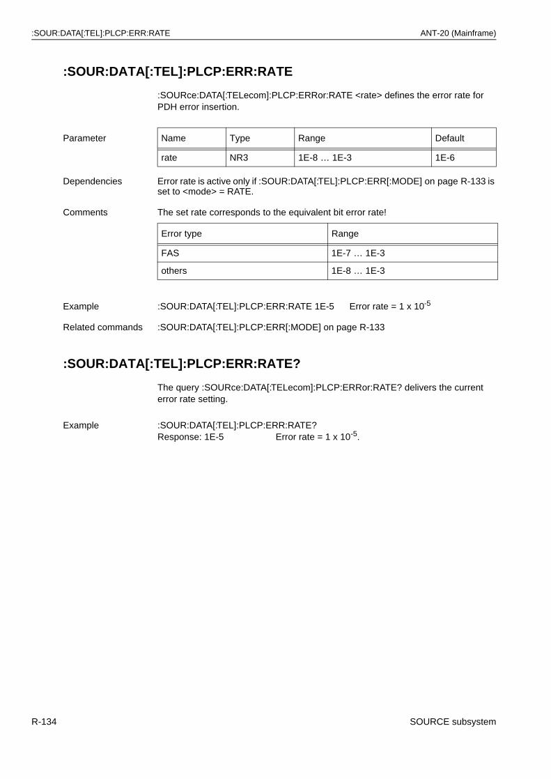
:SOUR:DATA[:TEL]:PLCP:ERR:RATE ANT-20 (Mainframe)
:SOUR:DATA[:TEL]:PLCP:ERR:RATE
:SOURce:DATA[:TELecom]:PLCP:ERRor:RATE <rate> defines the error rate for PDH error insertion.
:SOUR:DATA[:TEL]:PLCP:ERR:RATE?
The query :SOURce:DATA[:TELecom]:PLCP:ERRor:RATE? delivers the current error rate setting.
Parameter Name Type Range Default
rate NR3 1E-8 … 1E-3 1E-6
Dependencies Error rate is active only if :SOUR:DATA[:TEL]:PLCP:ERR[:MODE] on page R-133 is set to <mode> = RATE.
Comments The set rate corresponds to the equivalent bit error rate!
Error type Range
FAS 1E-7 … 1E-3
others 1E-8 … 1E-3
Example :SOUR:DATA[:TEL]:PLCP:ERR:RATE 1E-5 Error rate = 1 x 10⁻⁵
Related commands :SOUR:DATA[:TEL]:PLCP:ERR[:MODE] on page R-133
Example :SOUR:DATA[:TEL]:PLCP:ERR:RATE?Response: 1E-5 Error rate = 1 x 10⁻⁵.
R-134 SOURCE subsystem
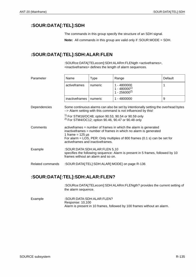
ANT-20 (Mainframe) :SOUR:DATA[:TEL]:SDH
:SOUR:DATA[:TEL]:SDH
The commands in this group specify the structure of an SDH signal.
Note: All commands in this group are valid only if :SOUR:MODE = SDH.
:SOUR:DATA[:TEL]:SDH:ALAR:FLEN
:SOURce:DATA[:TELecom]:SDH:ALARm:FLENgth <activeframes>, <inactiveframes> defines the length of alarm sequences.
:SOUR:DATA[:TEL]:SDH:ALAR:FLEN?
:SOURce:DATA[:TELecom]:SDH:ALARm:FLENgth? provides the current setting of the alarm sequence.
Parameter Name Type Range Default
activeframes numeric 1 - 48000001 - 4800001)
1 - 2560002)
1
inactiveframes numeric 1 - 4800000 9
Dependencies Some continuous alarms can also be set by intentionally setting the overhead bytes --> Alarm setting with this command is not influenced by this!1) For STM16/OC48; option 90.53, 90.54 or 90.59 only2) For STM4/OC12; option 90.46, 90.47 or 90.48 only
Comments activeframes = number of frames in which the alarm is generatedinactiveframes = number of frames in which no alarm is generated1 frame = 125 µsFor alarm = LOS, PER: Only multiples of 800 frames (0.1 s) can be set for activeframes and inactiveframes.
Example :SOUR:DATA:SDH:ALAR:FLEN 5,10specifies the following sequence: Alarm is present in 5 frames, followed by 10 frames without an alarm and so on.
Related commands :SOUR:DATA[:TEL]:SDH:ALAR[:MODE] on page R-136
Example :SOUR:DATA:SDH:ALAR:FLEN?Response: 10,100Alarm is present in 10 frames, followed by 100 frames without an alarm.
SOURCE subsystem R-135
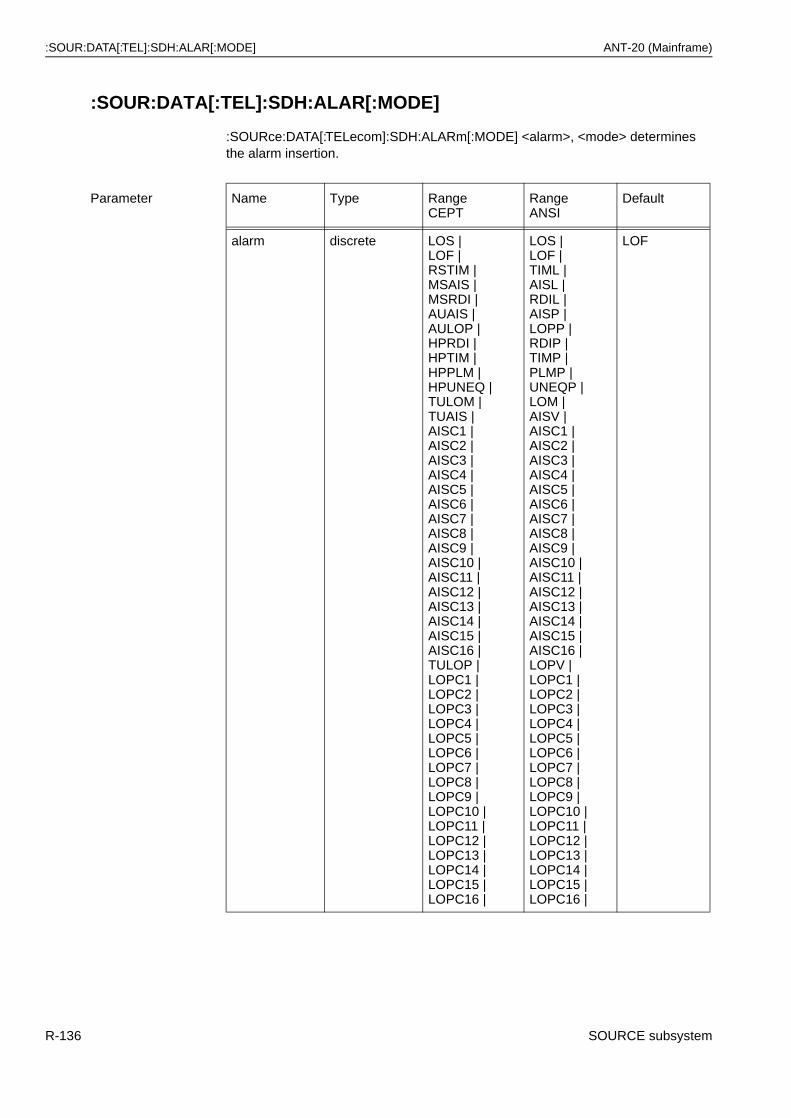
:SOUR:DATA[:TEL]:SDH:ALAR[:MODE] ANT-20 (Mainframe)
:SOUR:DATA[:TEL]:SDH:ALAR[:MODE]
:SOURce:DATA[:TELecom]:SDH:ALARm[:MODE] <alarm>, <mode> determines the alarm insertion.
Parameter Name Type RangeCEPT
RangeANSI
Default
alarm discrete LOS | LOF |RSTIM |MSAIS |MSRDI |AUAIS |AULOP |HPRDI |HPTIM |HPPLM |HPUNEQ |TULOM |TUAIS |AISC1 |AISC2 |AISC3 |AISC4 |AISC5 |AISC6 |AISC7 |AISC8 |AISC9 |AISC10 |AISC11 |AISC12 |AISC13 |AISC14 |AISC15 |AISC16 |TULOP |LOPC1 |LOPC2 |LOPC3 |LOPC4 |LOPC5 |LOPC6 |LOPC7 |LOPC8 |LOPC9 |LOPC10 |LOPC11 |LOPC12 |LOPC13 |LOPC14 |LOPC15 |LOPC16 |
LOS | LOF |TIML |AISL |RDIL |AISP |LOPP |RDIP |TIMP |PLMP |UNEQP |LOM |AISV |AISC1 |AISC2 |AISC3 |AISC4 |AISC5 |AISC6 |AISC7 |AISC8 |AISC9 |AISC10 |AISC11 |AISC12 |AISC13 |AISC14 |AISC15 |AISC16 |LOPV |LOPC1 |LOPC2 |LOPC3 |LOPC4 |LOPC5 |LOPC6 |LOPC7 |LOPC8 |LOPC9 |LOPC10 |LOPC11 |LOPC12 |LOPC13 |LOPC14 |LOPC15 |LOPC16 |
LOF
R-136 SOURCE subsystem
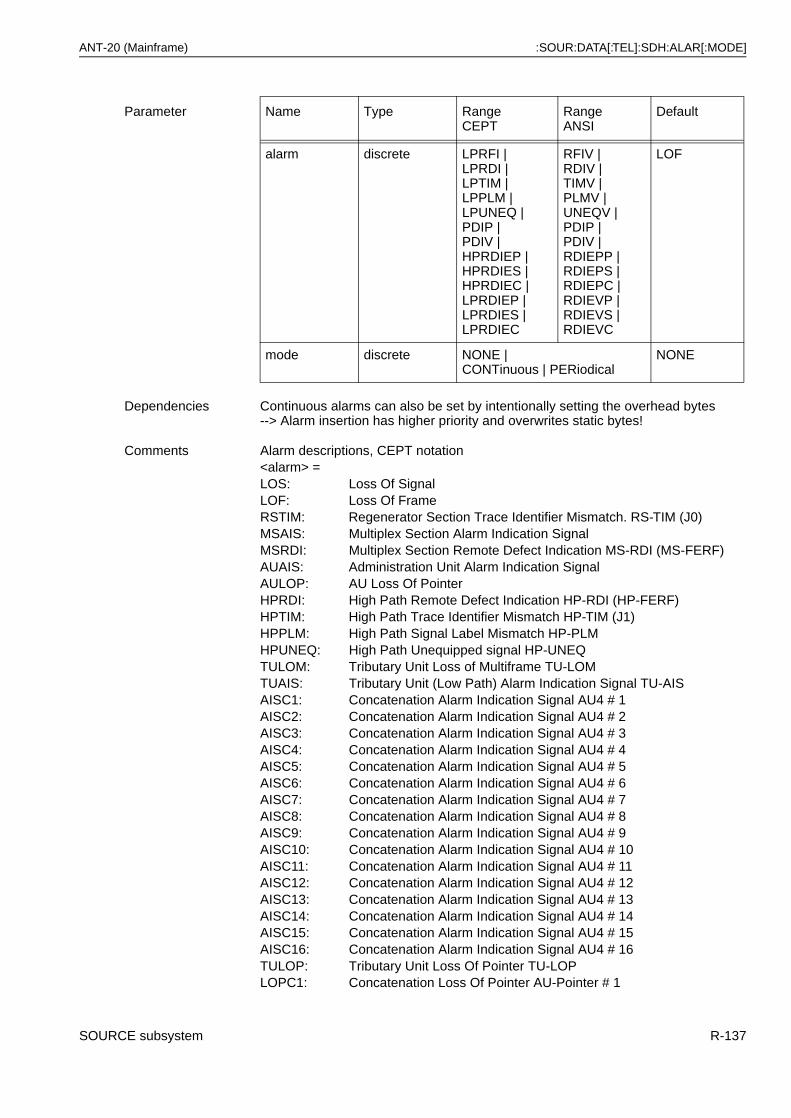
ANT-20 (Mainframe) :SOUR:DATA[:TEL]:SDH:ALAR[:MODE]
alarm discrete LPRFI |LPRDI |LPTIM |LPPLM |LPUNEQ |PDIP |PDIV |HPRDIEP |HPRDIES |HPRDIEC |LPRDIEP |LPRDIES |LPRDIEC
RFIV |RDIV |TIMV |PLMV |UNEQV |PDIP |PDIV |RDIEPP |RDIEPS |RDIEPC |RDIEVP |RDIEVS |RDIEVC
LOF
mode discrete NONE |CONTinuous | PERiodical
NONE
Dependencies Continuous alarms can also be set by intentionally setting the overhead bytes--> Alarm insertion has higher priority and overwrites static bytes!
Comments Alarm descriptions, CEPT notation<alarm> =LOS: Loss Of SignalLOF: Loss Of FrameRSTIM: Regenerator Section Trace Identifier Mismatch. RS-TIM (J0)MSAIS: Multiplex Section Alarm Indication SignalMSRDI: Multiplex Section Remote Defect Indication MS-RDI (MS-FERF)AUAIS: Administration Unit Alarm Indication SignalAULOP: AU Loss Of PointerHPRDI: High Path Remote Defect Indication HP-RDI (HP-FERF)HPTIM: High Path Trace Identifier Mismatch HP-TIM (J1)HPPLM: High Path Signal Label Mismatch HP-PLMHPUNEQ: High Path Unequipped signal HP-UNEQTULOM: Tributary Unit Loss of Multiframe TU-LOMTUAIS: Tributary Unit (Low Path) Alarm Indication Signal TU-AISAISC1: Concatenation Alarm Indication Signal AU4 # 1AISC2: Concatenation Alarm Indication Signal AU4 # 2AISC3: Concatenation Alarm Indication Signal AU4 # 3AISC4: Concatenation Alarm Indication Signal AU4 # 4AISC5: Concatenation Alarm Indication Signal AU4 # 5AISC6: Concatenation Alarm Indication Signal AU4 # 6AISC7: Concatenation Alarm Indication Signal AU4 # 7AISC8: Concatenation Alarm Indication Signal AU4 # 8AISC9: Concatenation Alarm Indication Signal AU4 # 9AISC10: Concatenation Alarm Indication Signal AU4 # 10AISC11: Concatenation Alarm Indication Signal AU4 # 11AISC12: Concatenation Alarm Indication Signal AU4 # 12AISC13: Concatenation Alarm Indication Signal AU4 # 13AISC14: Concatenation Alarm Indication Signal AU4 # 14AISC15: Concatenation Alarm Indication Signal AU4 # 15AISC16: Concatenation Alarm Indication Signal AU4 # 16TULOP: Tributary Unit Loss Of Pointer TU-LOPLOPC1: Concatenation Loss Of Pointer AU-Pointer # 1
Parameter Name Type RangeCEPT
RangeANSI
Default
SOURCE subsystem R-137
:SOUR:DATA[:TEL]:SDH:ALAR[:MODE] ANT-20 (Mainframe)
LOPC2: Concatenation Loss Of Pointer AU-Pointer # 2LOPC3: Concatenation Loss Of Pointer AU-Pointer # 3LOPC4: Concatenation Loss Of Pointer AU-Pointer # 4LOPC5: Concatenation Loss Of Pointer AU-Pointer # 5LOPC6: Concatenation Loss Of Pointer AU-Pointer # 6LOPC7: Concatenation Loss Of Pointer AU-Pointer # 7LOPC8: Concatenation Loss Of Pointer AU-Pointer # 8LOPC9: Concatenation Loss Of Pointer AU-Pointer # 9LOPC10: Concatenation Loss Of Pointer AU-Pointer # 10LOPC11: Concatenation Loss Of Pointer AU-Pointer # 11LOPC12: Concatenation Loss Of Pointer AU-Pointer # 12LOPC13: Concatenation Loss Of Pointer AU-Pointer # 13LOPC14: Concatenation Loss Of Pointer AU-Pointer # 14LOPC15: Concatenation Loss Of Pointer AU-Pointer # 15LOPC16: Concatenation Loss Of Pointer AU-Pointer # 16LPRDI: Low Path Remote Defect Indication LP-RDI (LP-FERF)LPRFI: Low Path Remote Failure IndicationLPUNEQ: Low Path Unequipped signalLPTIM: Low Path Trace Identifier Mismatch LP-TIMLPPLM: Low Path Signal Label Mismatch LP-PLMPDIP: Payload Defect Indication STS-PathPDIV: Payload Defect Indication VT-PathHPRDIEP: High Path Remote Defect Indication Enhanced PayloadHPRDIES: High Path Remote Defect Indication Enhanced ServerHPRDIEC: High Path Remote Defect Indication Enhanced ConnectivityLPRDIEP: Low Path Remote Defect Indication Enhanced PayloadLPRDIES: Low Path Remote Defect Indication Enhanced ServerLPRDIEC: Low Path Remote Defect Indication Enhanced Connectivity
Alarm descriptions, ANSI notation<alarm> =LOS: Loss Of SignalLOF: Loss Of FrameTIML: Trace Identifier Mismatch Line (J0)AISL: Alarm Indication Signal LineRDIL: Remote Defect Indication LineAISP: Alarm Indication Signal STS-PathLOPP: Loss Of Pointer STS-PathRDIP: Remote Defect Indication STS-PathTIMP: Trace Identifier Mismatch STS-Path (J1)PLMP: Signal Label Mismatch STS-PathUNEQ: Unequipped signal STS-PathLOM: Loss of Multiframe VT-PathAISV: Alarm Indication Signal VT-PathAISC1: Concatenation Alarm Indication Signal STS-Path # 1AISC2: Concatenation Alarm Indication Signal STS-Path # 2AISC3: Concatenation Alarm Indication Signal STS-Path # 3AISC4: Concatenation Alarm Indication Signal STS-Path # 4AISC5: Concatenation Alarm Indication Signal STS-Path # 5AISC6: Concatenation Alarm Indication Signal STS-Path # 6AISC7: Concatenation Alarm Indication Signal STS-Path # 7AISC8: Concatenation Alarm Indication Signal STS-Path # 8AISC9: Concatenation Alarm Indication Signal STS-Path # 9AISC10: Concatenation Alarm Indication Signal STS-Path # 10
R-138 SOURCE subsystem
ANT-20 (Mainframe) :SOUR:DATA[:TEL]:SDH:ALAR[:MODE]
AISC11: Concatenation Alarm Indication Signal STS-Path # 11AISC12: Concatenation Alarm Indication Signal STS-Path # 12AISC13: Concatenation Alarm Indication Signal STS-Path # 13AISC14: Concatenation Alarm Indication Signal STS-Path # 14AISC15: Concatenation Alarm Indication Signal STS-Path # 15AISC16: Concatenation Alarm Indication Signal STS-Path # 16LOPV: Loss Of Pointer VT-PathLOPC1: Concatenation Loss Of Pointer STS-Path # 1LOPC2: Concatenation Loss Of Pointer STS-Path # 2LOPC3: Concatenation Loss Of Pointer STS-Path # 3LOPC4: Concatenation Loss Of Pointer STS-Path # 4LOPC5: Concatenation Loss Of Pointer STS-Path # 5LOPC6: Concatenation Loss Of Pointer STS-Path # 6LOPC7: Concatenation Loss Of Pointer STS-Path # 7LOPC8: Concatenation Loss Of Pointer STS-Path # 8LOPC9: Concatenation Loss Of Pointer STS-Path # 9LOPC10: Concatenation Loss Of Pointer STS-Path # 10LOPC11: Concatenation Loss Of Pointer STS-Path # 11LOPC12: Concatenation Loss Of Pointer STS-Path # 12LOPC13: Concatenation Loss Of Pointer STS-Path # 13LOPC14: Concatenation Loss Of Pointer STS-Path # 14LOPC15: Concatenation Loss Of Pointer STS-Path # 15LOPC16: Concatenation Loss Of Pointer STS-Path # 16RDIV: Remote Defect Indication VT-PathRFIV: Remote Failure Indication VT-PathUNEQV: Unequipped signal VT-PathTIMV: Trace Identifier Mismatch VT-PathPLMV: Path Signal Label Mismatch VT-PathPDIP: Payload Defect Indication STS-PathPDIV: Payload Defect Indication VT-PathRDIEPP: Remote Defect Indication Enhanced Payload STS-PathRDIEPS: Remote Defect Indication Enhanced Server STS-PathRDIEPC: Remote Defect Indication Enhanced Connectivity STS-PathRDIEVP: Remote Defect Indication Enhanced Payload VT-PathRDIEVS: Remote Defect Indication Enhanced Server VT-PathRDIEVC: Remote Defect Indication Enhanced Connectivity VT-Path
<mode> =NONE: No alarm insertionCONTinuous: Continuous alarm insertionPERiodical: Periodic execution of the alarm sequence as defined by
:SOUR:DATA[:TEL]:SDH:ALAR:FLEN on page R-135See alarm generation tables in the Options Manual file for periodic alarms that are allowed for the various mapping options.
Example :SOUR:DATA:SDH:ALAR MSAIS, CONTgenerates a continuous MSAIS.
Related commands :SOUR:DATA[:TEL]:SDH:ALAR:FLEN on page R-135
SOURCE subsystem R-139
:SOUR:DATA[:TEL]:SDH:ALAR[:MODE]? ANT-20 (Mainframe)
:SOUR:DATA[:TEL]:SDH:ALAR[:MODE]?
:SOURce:DATA[:TELecom]:SDH:ALARm[:MODE]? provides the current setting of the alarm insertion.
Note: The corresponding command accepts the ITU-T and ANSI notation. The query however always returns the ITU-T notation.
:SOUR:DATA[:TEL]:SDH:BPOV:DATA
:SOURce:DATA[:TELecom]:SDH:BPOVerhead:DATA <byte>, <value> sets bytes of the VC4 (STS3CSPE) / VC3 (STS1SPE) high order POH (path overhead) of the background channels.
:SOUR:DATA[:TEL]:SDH:BPOV:DATA?
:SOURce:DATA[:TELecom]:SDH:BPOVerhead:DATA? <byte> provides the current settings of the high order POH (path overhead) of the background channels.
Dependencies Some continuous alarms can also be set by intentionally setting the overhead bytes --> The response to this query may be NONE in such cases!
Example :SOUR:DATA:SDH:ALAR?Response: LOF,PER if a LOF alarm sequence is activated.
Parameter Name Type Range Default
byte discrete J1 | C2 | G1 | F2 | F3| K3(Z4) | N1
none
value numeric #H00 - #HFF or#B00000000 - #B11111111 or 0 - 255
none
Dependencies None
Comments This command allows individual setting of the designated POH bytes in allbackground channels simultaneously. For the default setting, see :SOUR:DATA[:TEL]:SDH:BPOV:PRES on page R-143.
Example :SOUR:DATA:SDH:BPOV:DATA C2, #H34 sets C2 byte to 34hex.
Related commands :SOUR:DATA[:TEL]:SDH:BPOV:HPTR on page R-142:SOUR:DATA[:TEL]:SDH:BPOV:PRES on page R-143
Example :SOUR:DATA:SDH:BPOV:DATA? C2Response: 128 C2 byte is set to 80hex.
R-140 SOURCE subsystem
ANT-20 (Mainframe) :SOUR:DATA[:TEL]:SDH:BPOV:DATA:BLOC
:SOUR:DATA[:TEL]:SDH:BPOV:DATA:BLOC
:SOURce:DATA[:TELecom]:SDH:BPOVerhead:DATA:BLOCk <J1>, <B3>,<C2>, <G1>, <F2>, <H4>, <F3>, <K3>, <N1> sets all 9 bytes of theVC4 (STS3CSPE)/VC3 (STS1SPE) high order POH (path overhead) of the background channels.
Parameter Nine successive <numeric> values are expected, which set the complete POH.
Name Type Range Default
J1 numeric #H00 - #HFF or#B00000000 - #B11111111 or 0 - 255
none
B3 numeric Automatically generated --> should be set to 0
0
C2 numeric #H00 - #HFF or#B00000000 - #B11111111 or 0 - 255
none
G1 numeric #H00 - #HFF or#B00000000 - #B11111111 or 0 - 255
none
F2 numeric #H00 - #HFF or#B00000000 - #B11111111 or 0 - 255
none
H4 numeric Automatically generated --> should be set to #HFF
#HFF
F3 numeric #H00 - #HFF or#B00000000 - #B11111111 or 0 - 255
none
K3(Z4) numeric #H00 - #HFF or#B00000000 - #B11111111 or 0 - 255
none
N1 numeric #H00 - #HFF or#B00000000 - #B11111111 or 0 - 255
none
Dependencies Continuous alarms can also be generated here. Error/alarm insertion has higher priority and overwrites static settings!
Comments B3 and the H4 byte of the POH cannot be set since their values are automatically generated.
Example :SOUR:DATA:SDH:BPOV:DATA:BLOC 0,0,4,0,0,#HFF,0,0,0
Related commands :SOUR:DATA[:TEL]:SDH:BPOV:DATA on page R-140
SOURCE subsystem R-141
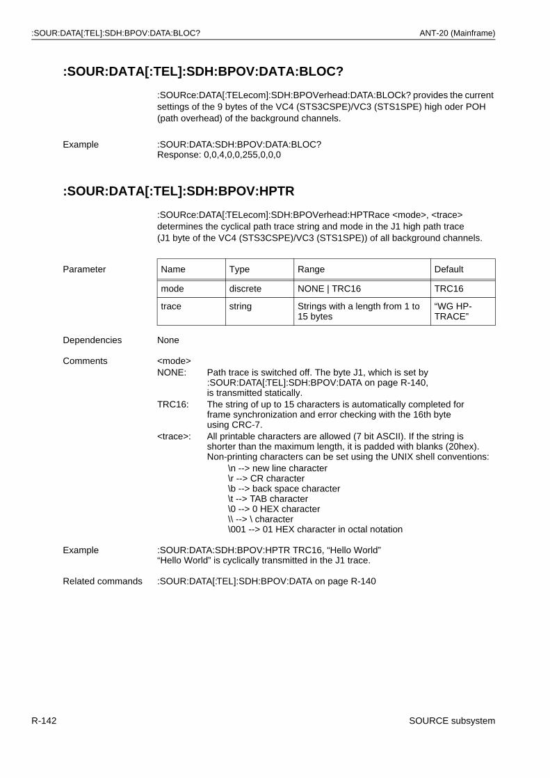
:SOUR:DATA[:TEL]:SDH:BPOV:DATA:BLOC? ANT-20 (Mainframe)
:SOUR:DATA[:TEL]:SDH:BPOV:DATA:BLOC?
:SOURce:DATA[:TELecom]:SDH:BPOVerhead:DATA:BLOCk? provides the current settings of the 9 bytes of the VC4 (STS3CSPE)/VC3 (STS1SPE) high oder POH (path overhead) of the background channels.
:SOUR:DATA[:TEL]:SDH:BPOV:HPTR
:SOURce:DATA[:TELecom]:SDH:BPOVerhead:HPTRace <mode>, <trace> determines the cyclical path trace string and mode in the J1 high path trace(J1 byte of the VC4 (STS3CSPE)/VC3 (STS1SPE)) of all background channels.
Example :SOUR:DATA:SDH:BPOV:DATA:BLOC?Response: 0,0,4,0,0,255,0,0,0
Parameter Name Type Range Default
mode discrete NONE | TRC16 TRC16
trace string Strings with a length from 1 to 15 bytes
“WG HP-TRACE”
Dependencies None
Comments <mode>NONE: Path trace is switched off. The byte J1, which is set by
:SOUR:DATA[:TEL]:SDH:BPOV:DATA on page R-140,is transmitted statically.
TRC16: The string of up to 15 characters is automatically completed forframe synchronization and error checking with the 16th byte using CRC-7.
<trace>: All printable characters are allowed (7 bit ASCII). If the string isshorter than the maximum length, it is padded with blanks (20hex).Non-printing characters can be set using the UNIX shell conventions:
\n --> new line character\r --> CR character\b --> back space character\t --> TAB character\0 --> 0 HEX character\\ --> \ character\001 --> 01 HEX character in octal notation
Example :SOUR:DATA:SDH:BPOV:HPTR TRC16, “Hello World”“Hello World” is cyclically transmitted in the J1 trace.
Related commands :SOUR:DATA[:TEL]:SDH:BPOV:DATA on page R-140
R-142 SOURCE subsystem
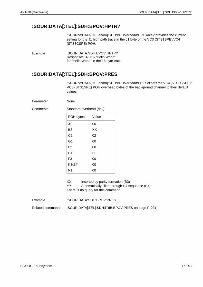
ANT-20 (Mainframe) :SOUR:DATA[:TEL]:SDH:BPOV:HPTR?
:SOUR:DATA[:TEL]:SDH:BPOV:HPTR?
:SOURce:DATA[:TELecom]:SDH:BPOVerhead:HPTRace? provides the current setting for the J1 high path trace in the J1 byte of the VC3 (STS1SPE)/VC4 (STS3CSPE) POH.
:SOUR:DATA[:TEL]:SDH:BPOV:PRES
:SOURce:DATA[:TELecom]:SDH:BPOVerhead:PRESet sets the VC4 (STS3CSPE)/VC3 (STS1SPE) POH overhead bytes of the background channel to their default values.
Example :SOUR:DATA:SDH:BPOV:HPTR?Response: TRC16,“Hello World”for “Hello World” in the 16 byte trace.
Parameter None
Comments Standard overhead (hex)
POH bytes Value
J1
B3
C2
G1
F2
H4
F3
K3(Z4)
N1
00
XX
02
00
00
FF
00
00
00
XX: Inserted by parity formation (B3)YY: Automatically filled through H4 sequence (H4)There is no query for this command.
Example :SOUR:DATA:SDH:BPOV:PRES
Related commands :SOUR:DATA[:TEL]:SDH:TRIB:BPOV:PRES on page R-231
SOURCE subsystem R-143
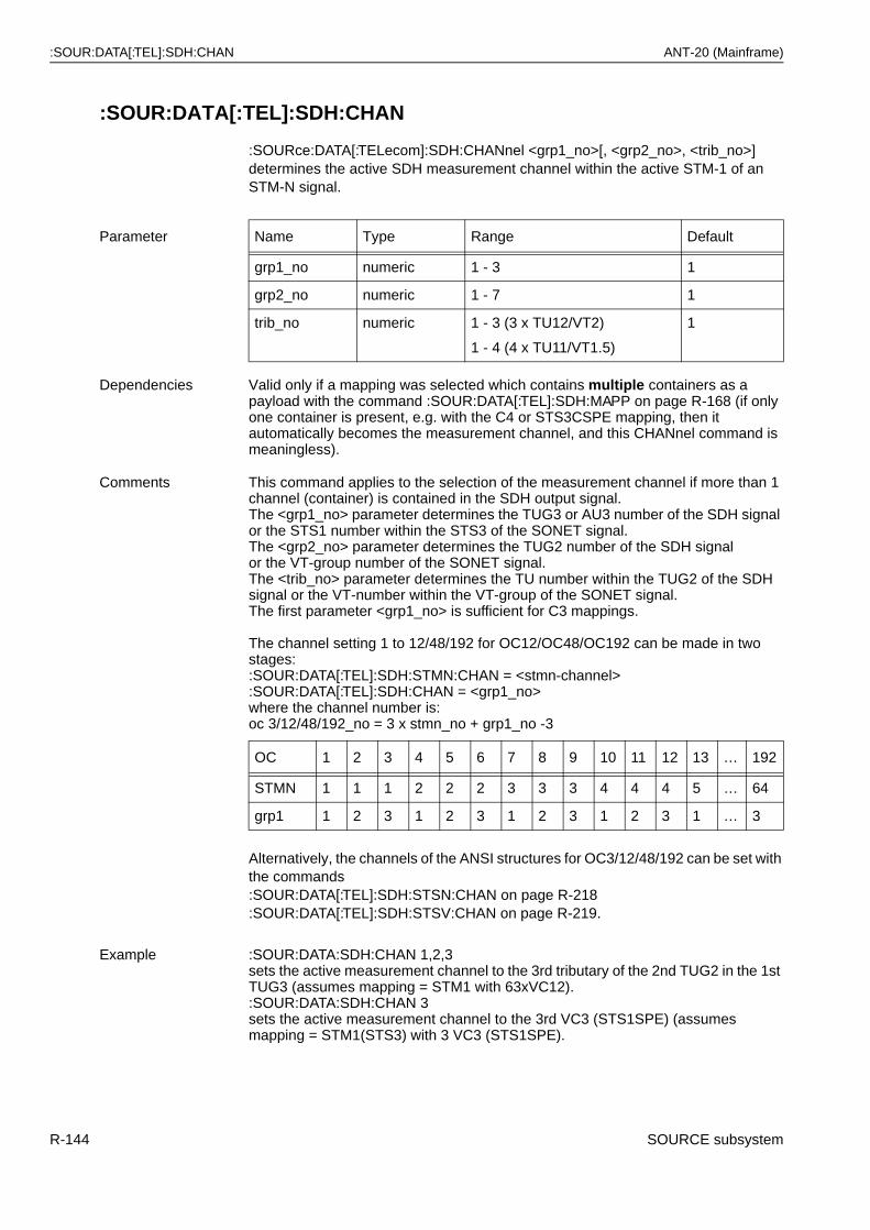
:SOUR:DATA[:TEL]:SDH:CHAN ANT-20 (Mainframe)
:SOUR:DATA[:TEL]:SDH:CHAN
:SOURce:DATA[:TELecom]:SDH:CHANnel <grp1_no>[, <grp2_no>, <trib_no>] determines the active SDH measurement channel within the active STM-1 of an STM-N signal.
Alternatively, the channels of the ANSI structures for OC3/12/48/192 can be set with the commands:SOUR:DATA[:TEL]:SDH:STSN:CHAN on page R-218:SOUR:DATA[:TEL]:SDH:STSV:CHAN on page R-219.
Parameter Name Type Range Default
grp1_no numeric 1 - 3 1
grp2_no numeric 1 - 7 1
trib_no numeric 1 - 3 (3 x TU12/VT2)
1 - 4 (4 x TU11/VT1.5)
1
Dependencies Valid only if a mapping was selected which contains multiple containers as a payload with the command :SOUR:DATA[:TEL]:SDH:MAPP on page R-168 (if only one container is present, e.g. with the C4 or STS3CSPE mapping, then it automatically becomes the measurement channel, and this CHANnel command is meaningless).
Comments This command applies to the selection of the measurement channel if more than 1 channel (container) is contained in the SDH output signal.The <grp1_no> parameter determines the TUG3 or AU3 number of the SDH signal or the STS1 number within the STS3 of the SONET signal.The <grp2_no> parameter determines the TUG2 number of the SDH signalor the VT-group number of the SONET signal.The <trib_no> parameter determines the TU number within the TUG2 of the SDH signal or the VT-number within the VT-group of the SONET signal.The first parameter <grp1_no> is sufficient for C3 mappings.
The channel setting 1 to 12/48/192 for OC12/OC48/OC192 can be made in two stages::SOUR:DATA[:TEL]:SDH:STMN:CHAN = <stmn-channel> :SOUR:DATA[:TEL]:SDH:CHAN = <grp1_no>where the channel number is:oc 3/12/48/192_no = 3 x stmn_no + grp1_no -3
OC 1 2 3 4 5 6 7 8 9 10 11 12 13 … 192
STMN 1 1 1 2 2 2 3 3 3 4 4 4 5 … 64
grp1 1 2 3 1 2 3 1 2 3 1 2 3 1 … 3
Example :SOUR:DATA:SDH:CHAN 1,2,3sets the active measurement channel to the 3rd tributary of the 2nd TUG2 in the 1st TUG3 (assumes mapping = STM1 with 63xVC12).:SOUR:DATA:SDH:CHAN 3sets the active measurement channel to the 3rd VC3 (STS1SPE) (assumes mapping = STM1(STS3) with 3 VC3 (STS1SPE).
R-144 SOURCE subsystem
ANT-20 (Mainframe) :SOUR:DATA[:TEL]:SDH:CHAN?
:SOUR:DATA[:TEL]:SDH:CHAN?
:SOURce:DATA[:TELecom]:SDH:CHANnel? provides the current channel selection of the SDH output signal.
Related commands :SOUR:DATA[:TEL]:SDH:RATE on page R-213:SOUR:DATA[:TEL]:SDH:MAPP on page R-168:SOUR:DATA[:TEL]:SDH:STMN:CHAN on page R-217:SOUR:DATA[:TEL]:SDH:STSN:CHAN on page R-218:SOUR:DATA[:TEL]:SDH:STSV:CHAN on page R-219
Example :SOUR:DATA:SDH:CHAN?Response: 1,2,3SDH: Measurement channel is in the 3rd tributary of the 2nd TUG2 in the 1st TUG3. SONET: Measurement channel is in the 3rd tributary of the 2nd VT group in the 1st STS1SPE.
SOURCE subsystem R-145

:SOUR:DATA[:TEL]:SDH:CONC:DPO2 ANT-20 (Mainframe)
:SOUR:DATA[:TEL]:SDH:CONC:DPO2
:SOURce:DATA[:TELecom]:SDH:CONCatenate:DPOinter <value> determines the virtual concatenated delta pointer value of POH #2.
:SOUR:DATA[:TEL]:SDH:CONC:DPO2?
:SOURce:DATA[:TELecom]:SDH:CONCatenate:DPOinter2? provides the virtual concatenated delta pointer value of POH #2.
Parameter Name Type Range Default
value numeric -40 to 40 0
Dependencies :SOUR:DATA[:TEL]:SDH:MAPP:CONC[:MODE] on page R-170 must be set to VIRTual.
Comments In the case of “virtual concatenation”, this command can be used to set the pointer offset of the 2nd POH relative to the pointer of the 1st POH. The pointer of the 1st POH represents the “guide pointer”. If the guide pointer changes, e.g. due to pointer actions (see also :SOUR:DATA[:TEL]:SDH:POIN[:ACT] on page R-198), the pointer for POH #2 also always changes simultaneously. However, the difference between the guide pointer and the pointer of the 2nd POH always conforms to the value set with this command.
Example:
Pointer for 1st POH = 100 and delta pointer for 2nd POH = -10, so the absolute pointer value of the 2nd POH is 90. If the value of the guide pointer now changes to 101, then the value of the 2nd pointer will be 91.
Example :SOUR:DATA:SDH:CONC:DPO2 10 sets the delta pointer value to 10.
Related commands :SOUR:DATA[:TEL]:SDH:CONC:POIN[:ACT] on page R-149
Example :SOUR:DATA:SDH:CONC:DPO2?Response: 10
R-146 SOURCE subsystem
ANT-20 (Mainframe) :SOUR:DATA[:TEL]:SDH:CONC:DPO3
:SOUR:DATA[:TEL]:SDH:CONC:DPO3
:SOURce:DATA[:TELecom]:SDH:CONCatenate:DPOinter <value> determines the virtual concatenated delta pointer value of POH #3.
:SOUR:DATA[:TEL]:SDH:CONC:DPO3?
:SOURce:DATA[:TELecom]:SDH:CONCatenate:DPOinter3? provides the virtual concatenated delta pointer value of POH #3.
Parameter Name Type Range Default
value numeric -40 to 40 0
Dependencies :SOUR:DATA[:TEL]:SDH:MAPP:CONC[:MODE] on page R-170 must be set to VIRTual.
Comments In the case of “virtual concatenation”, this command can be used to set the pointer offset of the 3rd POH relative to the pointer of the 1st POH. The pointer of the 1st POH represents the “guide pointer”. If the guide pointer changes, e.g. due to pointer actions (see also :SOUR:DATA[:TEL]:SDH:POIN[:ACT] on page R-198), the pointer for POH #3 also always changes simultaneously. However, the difference between the guide pointer and the pointer of the 3rd POH always conforms to the value set with this command.
Example:
Pointer for 1st POH = 100 and delta pointer for 3rd POH = -10, so the absolute pointer value of the 3rd POH is 90. If the value of the guide pointer now changes to 101, then the value of the 3rd pointer will be 91.
Example :SOUR:DATA:SDH:CONC:DPO3 10 sets the delta pointer value to 10.
Related commands :SOUR:DATA[:TEL]:SDH:CONC:POIN[:ACT] on page R-149
Example :SOUR:DATA:SDH:CONC:DPO3?Response: 10
SOURCE subsystem R-147
:SOUR:DATA[:TEL]:SDH:CONC:DPO4 ANT-20 (Mainframe)
:SOUR:DATA[:TEL]:SDH:CONC:DPO4
:SOURce:DATA[:TELecom]:SDH:CONCatenate:DPOinter <value> determines the virtual concatenated delta pointer value of POH #4.
:SOUR:DATA[:TEL]:SDH:CONC:DPO4?
:SOURce:DATA[:TELecom]:SDH:CONCatenate:DPOinter4? provides the virtual concatenated delta pointer value of POH #4.
Parameter Name Type Range Default
value numeric -40 to 40 0
Dependencies :SOUR:DATA[:TEL]:SDH:MAPP:CONC[:MODE] on page R-170 must be set to VIRTual.
Comments In the case of “virtual concatenation”, this command can be used to set the pointer offset of the 4th POH relative to the pointer of the 1st POH. The pointer of the 1st POH represents the “guide pointer”. If the guide pointer changes, e.g. due to pointer actions (see also :SOUR:DATA[:TEL]:SDH:POIN[:ACT] on page R-198), the pointer for POH #4 also always changes simultaneously. However, the difference between the guide pointer and the pointer of the 4th POH always conforms to the value set with this command.
Example:
Pointer for 1st POH = 100 and delta pointer for 4th POH = -10, so the absolute pointer value of the 4th POH is 90. If the value of the guide pointer now changes to 101, then the value of the 4th pointer will be 91.
Example :SOUR:DATA:SDH:CONC:DPO4 10 sets the delta pointer value to 10.
Related commands :SOUR:DATA[:TEL]:SDH:CONC:POIN[:ACT] on page R-149
Example :SOUR:DATA:SDH:CONC:DPO4?Response: 10
R-148 SOURCE subsystem
ANT-20 (Mainframe) :SOUR:DATA[:TEL]:SDH:CONC:POIN[:ACT]
:SOUR:DATA[:TEL]:SDH:CONC:POIN[:ACT]
:SOURce:DATA[:TELecom]:SDH:CONCatenate:POINter[:ACTion] <action> sets the AU/STS (administrative unit) pointer actions in the case of virtual concatenation of multiple containers.
Note: The run-time of this pointer setting command depends on the difference between old and new pointer values and may take up to 0.7 s. Use bit 0 of the :STAT:SEQ register to synchronize your controller.
:SOUR:DATA[:TEL]:SDH:CONC:POIN[:ACT]?
:SOURce:DATA[:TELecom]:SDH:CONCatenate:POINter[:ACTion]? provides the current setting of the concatenated delta pointer action.
Parameter Name Type Range Default
action discrete NONE | NPOinter NONE
Dependencies :SOUR:DATA[:TEL]:SDH:MAPP:CONC[:MODE] on page R-170 must be set to VIRTual.
:SOUR:DATA[:TEL]:SDH:POIN[:ACT] on page R-198 must be set to NONE, as AU/STS pointer actions are not allowed at the same time.
Comments NONE: No pointer actionsNPOinter: New virtual concatenation delta pointer values as set by
:SOUR:DATA[:TEL]:SDH:CONC:DPO2,:SOUR:DATA[:TEL]:SDH:CONC:DPO3,:SOUR:DATA[:TEL]:SDH:CONC:DPO4 are activated.
Example :SOUR:DATA:SDH:CONC:POIN NPO sets new delta pointer values.
Related commands :SOUR:DATA[:TEL]:SDH:CONC:DPO2 on page R-146:SOUR:DATA[:TEL]:SDH:CONC:DPO3 on page R-147:SOUR:DATA[:TEL]:SDH:CONC:DPO4 on page R-148
Comments <NPO> is a volatile state and cannot be read with the query.
Example :SOUR:DATA:SDH:CONC:POIN?Response: NONE
SOURCE subsystem R-149
:SOUR:DATA[:TEL]:SDH:CONC:POV2:DATA ANT-20 (Mainframe)
:SOUR:DATA[:TEL]:SDH:CONC:POV2:DATA
:SOURce:DATA[:TELecom]:SDH:CONCatenate:POVerhead2:DATA <byte>, <value> sets bytes of the virtual concatenated POH # 2(path overhead).
:SOUR:DATA[:TEL]:SDH:CONC:POV2:DATA?
:SOURce:DATA[:TELecom]:SDH:CONCatenate:POVerhead2:DATA? <byte> provides the current settings of individual virtual concatenated POH # 2 bytes.
Parameter Name Type Range Default
byte discrete J1 | C2 | G1 | F2 | F3| K3(Z4) | N1
none
value numeric #H00 - #HFF or#B00000000 - #B11111111 or 0 - 255
none
Dependencies :SOUR:DATA[:TEL]:SDH:MAPP:CONC[:MODE] on page R-170 must be set to VIRTual.
Comments This command allows individual setting of the designated POH bytes. For the default setting, see :SOUR:DATA[:TEL]:SDH:CONC:POV2:PRES on page R-153.POH # 1 can be set with the command :SOUR:DATA[:TEL]:SDH:POV:DATA on page R-208.
Example :SOUR:DATA:SDH:CONC:POV2:DATA C2, #H34 sets C2 byte to 34hex.
Related commands :SOUR:DATA[:TEL]:SDH:CONC:POV2:DATA:BLOC on page R-151:SOUR:DATA[:TEL]:SDH:CONC:POV2:PRES on page R-153:SOUR:DATA[:TEL]:SDH:CONC:POV2:MODE on page R-152
Example :SOUR:DATA:SDH:CONC:POV2:DATA? C2Response: 128 C2 byte is set to 80hex.
RSOH
MSOH
AU-4 - Pointers
4 x 9 bytes 4 x 261 Bytes
#2
POH
#3#4
#1
R-150 SOURCE subsystem
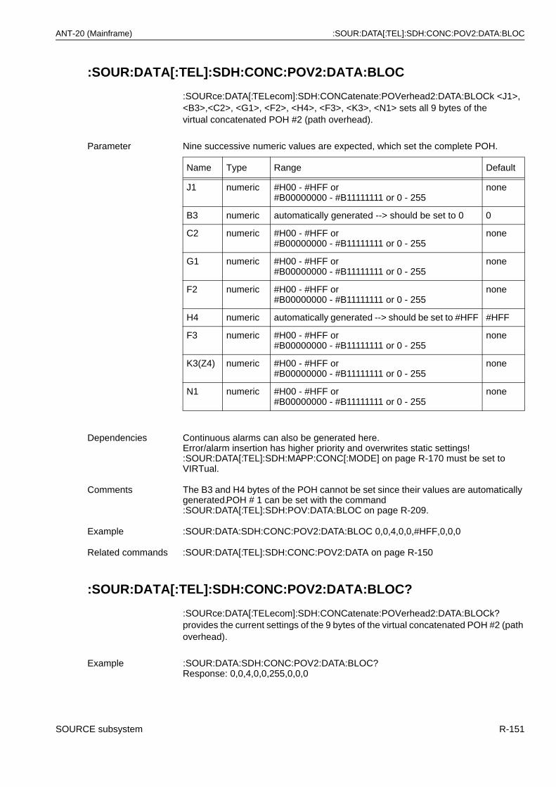
ANT-20 (Mainframe) :SOUR:DATA[:TEL]:SDH:CONC:POV2:DATA:BLOC
:SOUR:DATA[:TEL]:SDH:CONC:POV2:DATA:BLOC
:SOURce:DATA[:TELecom]:SDH:CONCatenate:POVerhead2:DATA:BLOCk <J1>, <B3>,<C2>, <G1>, <F2>, <H4>, <F3>, <K3>, <N1> sets all 9 bytes of thevirtual concatenated POH #2 (path overhead).
:SOUR:DATA[:TEL]:SDH:CONC:POV2:DATA:BLOC?
:SOURce:DATA[:TELecom]:SDH:CONCatenate:POVerhead2:DATA:BLOCk? provides the current settings of the 9 bytes of the virtual concatenated POH #2 (path overhead).
Parameter Nine successive numeric values are expected, which set the complete POH.
Name Type Range Default
J1 numeric #H00 - #HFF or#B00000000 - #B11111111 or 0 - 255
none
B3 numeric automatically generated --> should be set to 0 0
C2 numeric #H00 - #HFF or#B00000000 - #B11111111 or 0 - 255
none
G1 numeric #H00 - #HFF or#B00000000 - #B11111111 or 0 - 255
none
F2 numeric #H00 - #HFF or#B00000000 - #B11111111 or 0 - 255
none
H4 numeric automatically generated --> should be set to #HFF #HFF
F3 numeric #H00 - #HFF or#B00000000 - #B11111111 or 0 - 255
none
K3(Z4) numeric #H00 - #HFF or#B00000000 - #B11111111 or 0 - 255
none
N1 numeric #H00 - #HFF or#B00000000 - #B11111111 or 0 - 255
none
Dependencies Continuous alarms can also be generated here. Error/alarm insertion has higher priority and overwrites static settings! :SOUR:DATA[:TEL]:SDH:MAPP:CONC[:MODE] on page R-170 must be set to VIRTual.
Comments The B3 and H4 bytes of the POH cannot be set since their values are automatically generated.POH # 1 can be set with the command :SOUR:DATA[:TEL]:SDH:POV:DATA:BLOC on page R-209.
Example :SOUR:DATA:SDH:CONC:POV2:DATA:BLOC 0,0,4,0,0,#HFF,0,0,0
Related commands :SOUR:DATA[:TEL]:SDH:CONC:POV2:DATA on page R-150
Example :SOUR:DATA:SDH:CONC:POV2:DATA:BLOC?Response: 0,0,4,0,0,255,0,0,0
SOURCE subsystem R-151
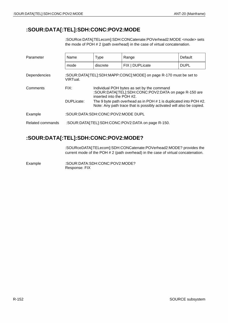
:SOUR:DATA[:TEL]:SDH:CONC:POV2:MODE ANT-20 (Mainframe)
:SOUR:DATA[:TEL]:SDH:CONC:POV2:MODE
:SOURce:DATA[:TELecom]:SDH:CONCatenate:POVerhead2:MODE <mode> sets the mode of POH # 2 (path overhead) in the case of virtual concatenation.
:SOUR:DATA[:TEL]:SDH:CONC:POV2:MODE?
:SOURceDATA[:TELecom]:SDH:CONCatenate:POVerhead2:MODE? provides the current mode of the POH # 2 (path overhead) in the case of virtual concatenation.
Parameter Name Type Range Default
mode discrete FIX | DUPLicate DUPL
Dependencies :SOUR:DATA[:TEL]:SDH:MAPP:CONC[:MODE] on page R-170 must be set to VIRTual.
Comments FIX: Individual POH bytes as set by the command :SOUR:DATA[:TEL]:SDH:CONC:POV2:DATA on page R-150 are inserted into the POH #2.
DUPLicate: The 9 byte path overhead as in POH # 1 is duplicated into POH #2.Note: Any path trace that is possibly activated will also be copied.
Example :SOUR:DATA:SDH:CONC:POV2:MODE DUPL
Related commands :SOUR:DATA[:TEL]:SDH:CONC:POV2:DATA on page R-150.
Example :SOUR:DATA:SDH:CONC:POV2:MODE?Response: FIX
R-152 SOURCE subsystem
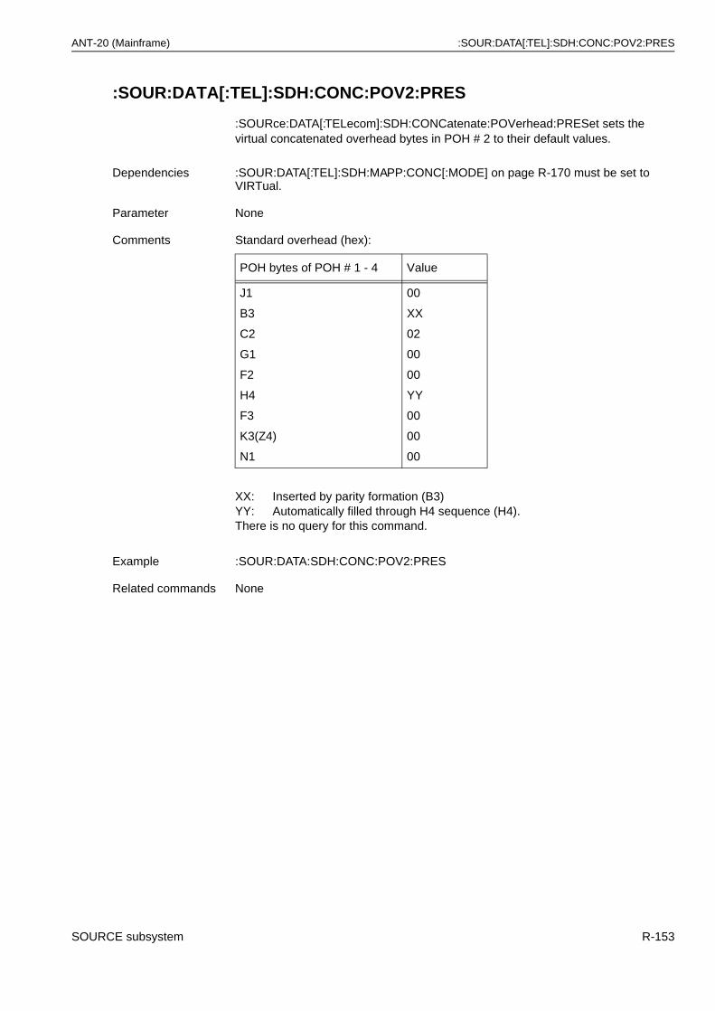
ANT-20 (Mainframe) :SOUR:DATA[:TEL]:SDH:CONC:POV2:PRES
:SOUR:DATA[:TEL]:SDH:CONC:POV2:PRES
:SOURce:DATA[:TELecom]:SDH:CONCatenate:POVerhead:PRESet sets the virtual concatenated overhead bytes in POH # 2 to their default values.
Dependencies :SOUR:DATA[:TEL]:SDH:MAPP:CONC[:MODE] on page R-170 must be set to VIRTual.
Parameter None
Comments Standard overhead (hex):
POH bytes of POH # 1 - 4 Value
J1
B3
C2
G1
F2
H4
F3
K3(Z4)
N1
00
XX
02
00
00
YY
00
00
00
XX: Inserted by parity formation (B3)YY: Automatically filled through H4 sequence (H4).There is no query for this command.
Example :SOUR:DATA:SDH:CONC:POV2:PRES
Related commands None
SOURCE subsystem R-153
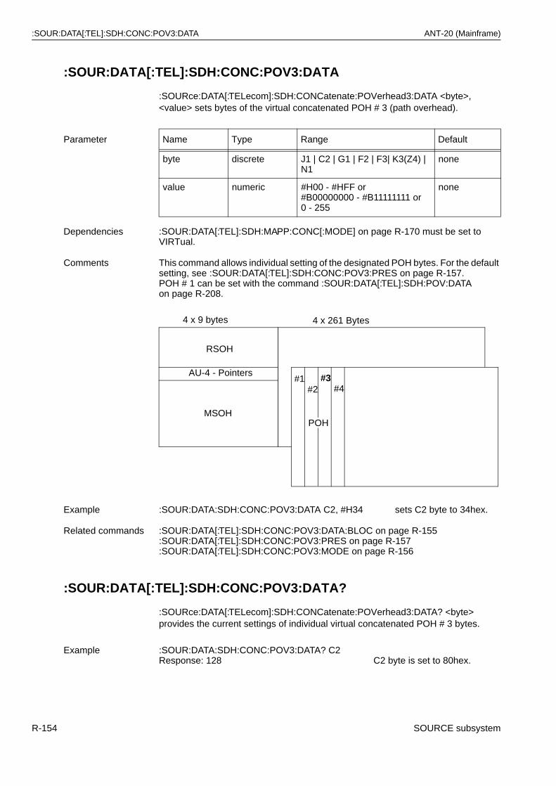
:SOUR:DATA[:TEL]:SDH:CONC:POV3:DATA ANT-20 (Mainframe)
:SOUR:DATA[:TEL]:SDH:CONC:POV3:DATA
:SOURce:DATA[:TELecom]:SDH:CONCatenate:POVerhead3:DATA <byte>, <value> sets bytes of the virtual concatenated POH # 3 (path overhead).
:SOUR:DATA[:TEL]:SDH:CONC:POV3:DATA?
:SOURce:DATA[:TELecom]:SDH:CONCatenate:POVerhead3:DATA? <byte> provides the current settings of individual virtual concatenated POH # 3 bytes.
Parameter Name Type Range Default
byte discrete J1 | C2 | G1 | F2 | F3| K3(Z4) | N1
none
value numeric #H00 - #HFF or#B00000000 - #B11111111 or 0 - 255
none
Dependencies :SOUR:DATA[:TEL]:SDH:MAPP:CONC[:MODE] on page R-170 must be set to VIRTual.
Comments This command allows individual setting of the designated POH bytes. For the default setting, see :SOUR:DATA[:TEL]:SDH:CONC:POV3:PRES on page R-157.POH # 1 can be set with the command :SOUR:DATA[:TEL]:SDH:POV:DATA on page R-208.
Example :SOUR:DATA:SDH:CONC:POV3:DATA C2, #H34 sets C2 byte to 34hex.
Related commands :SOUR:DATA[:TEL]:SDH:CONC:POV3:DATA:BLOC on page R-155:SOUR:DATA[:TEL]:SDH:CONC:POV3:PRES on page R-157:SOUR:DATA[:TEL]:SDH:CONC:POV3:MODE on page R-156
Example :SOUR:DATA:SDH:CONC:POV3:DATA? C2Response: 128 C2 byte is set to 80hex.
RSOH
MSOH
AU-4 - Pointers
4 x 9 bytes 4 x 261 Bytes
#2#3
#4#1
POH
R-154 SOURCE subsystem

ANT-20 (Mainframe) :SOUR:DATA[:TEL]:SDH:CONC:POV3:DATA:BLOC
:SOUR:DATA[:TEL]:SDH:CONC:POV3:DATA:BLOC
:SOURce:DATA[:TELecom]:SDH:CONCatenate:POVerhead3:DATA:BLOCk <J1>, <B3>,<C2>, <G1>, <F2>, <H4>, <F3>, <K3>, <N1> sets all 9 bytes of thevirtual concatenated POH # 3 (path overhead).
:SOUR:DATA[:TEL]:SDH:CONC:POV3:DATA:BLOC?
:SOURce:DATA[:TELecom]:SDH:CONCatenate:POVerhead3:DATA:BLOCk? provides the current settings of the 9 bytes of the virtual concatenated POH # 3 (path overhead).
Parameter Nine successive numeric values are expected, which set the complete POH.
Name Type Range Default
J1 numeric #H00 - #HFF or#B00000000 - #B11111111 or 0 - 255
none
B3 numeric automatically generated --> should be set to 0 0
C2 numeric #H00 - #HFF or#B00000000 - #B11111111 or 0 - 255
none
G1 numeric #H00 - #HFF or#B00000000 - #B11111111 or 0 - 255
none
F2 numeric #H00 - #HFF or#B00000000 - #B11111111 or 0 - 255
none
H4 numeric automatically generated --> should be set to #HFF #HFF
F3 numeric #H00 - #HFF or#B00000000 - #B11111111 or 0 - 255
none
K3(Z4) numeric #H00 - #HFF or#B00000000 - #B11111111 or 0 - 255
none
N1 numeric #H00 - #HFF or#B00000000 - #B11111111 or 0 - 255
none
Dependencies Continuous alarms can also be generated here. Error/alarm insertion has higher priority and overwrites static settings! :SOUR:DATA[:TEL]:SDH:MAPP:CONC[:MODE] on page R-170 must be set to VIRTual.
Comments The B3 and H4 bytes of the POH cannot be set since their values are automatically generated. POH # 1 can be set with the command :SOUR:DATA[:TEL]:SDH:POV:DATA:BLOC on page R-209.
Example :SOUR:DATA:SDH:CONC:POV3:DATA:BLOC 0,0,4,0,0,#HFF,0,0,0
Related commands :SOUR:DATA[:TEL]:SDH:CONC:POV3:DATA on page R-154
Example :SOUR:DATA:SDH:CONC:POV3:DATA:BLOC?Response: 0,0,4,0,0,255,0,0,0
SOURCE subsystem R-155

:SOUR:DATA[:TEL]:SDH:CONC:POV3:MODE ANT-20 (Mainframe)
:SOUR:DATA[:TEL]:SDH:CONC:POV3:MODE
:SOURce:DATA[:TELecom]:SDH:CONCatenate:POVerhead3:MODE <mode> sets the mode of POH # 3 (path overhead) in the case of virtual concatenation.
:SOUR:DATA[:TEL]:SDH:CONC:POV3:MODE?
:SOURceDATA[:TELecom]:SDH:CONCatenate:POVerhead3:MODE? provides the current mode of the POH # 3 (path overhead) in the case of virtual concatenation.
Parameter Name Type Range Default
mode discrete FIX | DUPLicate DUPL
Dependencies :SOUR:DATA[:TEL]:SDH:MAPP:CONC[:MODE] on page R-170 must be set to VIRTual.
Comments FIX: Individual POH bytes as set by the command :SOUR:DATA[:TEL]:SDH:CONC:POV3:DATA on page R-154 are inserted into the POH #3.
DUPLicate: The 9 byte path overhead as in POH # 1 is duplicated into POH #3.Note: Any path trace that is possibly activated will also be copied.
Example :SOUR:DATA:SDH:CONC:POV3:MODE DUPL
Related commands :SOUR:DATA[:TEL]:SDH:CONC:POV3:DATA on page R-154.
Example :SOUR:DATA:SDH:CONC:POV3:MODE?Response: FIX
R-156 SOURCE subsystem
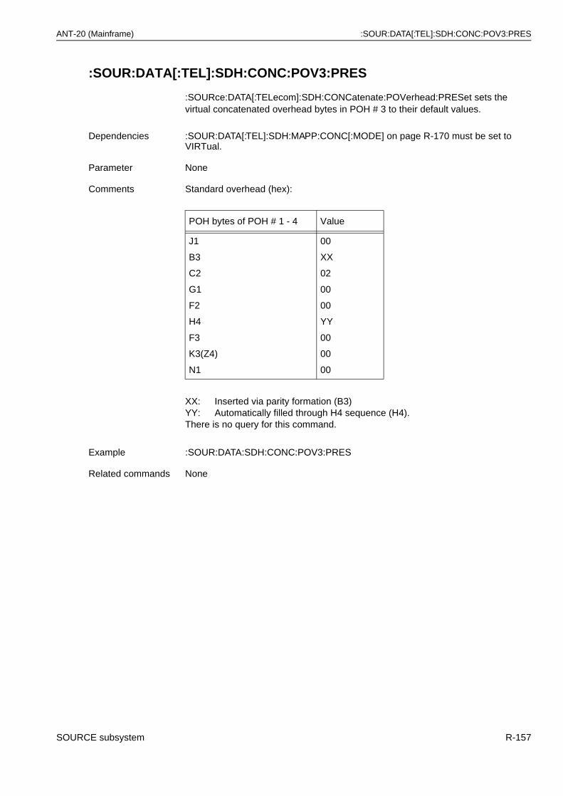
ANT-20 (Mainframe) :SOUR:DATA[:TEL]:SDH:CONC:POV3:PRES
:SOUR:DATA[:TEL]:SDH:CONC:POV3:PRES
:SOURce:DATA[:TELecom]:SDH:CONCatenate:POVerhead:PRESet sets the virtual concatenated overhead bytes in POH # 3 to their default values.
Dependencies :SOUR:DATA[:TEL]:SDH:MAPP:CONC[:MODE] on page R-170 must be set to VIRTual.
Parameter None
Comments Standard overhead (hex):
POH bytes of POH # 1 - 4 Value
J1
B3
C2
G1
F2
H4
F3
K3(Z4)
N1
00
XX
02
00
00
YY
00
00
00
XX: Inserted via parity formation (B3)YY: Automatically filled through H4 sequence (H4).There is no query for this command.
Example :SOUR:DATA:SDH:CONC:POV3:PRES
Related commands None
SOURCE subsystem R-157

:SOUR:DATA[:TEL]:SDH:CONC:POV4:DATA ANT-20 (Mainframe)
:SOUR:DATA[:TEL]:SDH:CONC:POV4:DATA
:SOURce:DATA[:TELecom]:SDH:CONCatenate:POVerhead4:DATA <byte>, <value> sets bytes of the virtual concatenated POH # 4 (path overhead).
:SOUR:DATA[:TEL]:SDH:CONC:POV4:DATA?
:SOURce:DATA[:TELecom]:SDH:CONCatenate:POVerhead4:DATA? <byte> provides the current settings of individual virtual concatenated POH # 4 bytes.
Parameter Name Type Range Default
byte discrete J1 | C2 | G1 | F2 | F3| K3(Z4) | N1
none
value numeric #H00 - #HFF or#B00000000 - #B11111111 or 0 - 255
none
Dependencies :SOUR:DATA[:TEL]:SDH:MAPP:CONC[:MODE] on page R-170 must be set to VIRTual.
Comments This command allows individual setting of the designated POH bytes. For the default setting, see :SOUR:DATA[:TEL]:SDH:CONC:POV4:PRES on page R-161.POH # 1 can be set with the command :SOUR:DATA[:TEL]:SDH:POV:DATA on page R-208.
Example :SOUR:DATA:SDH:CONC:POV4:DATA C2, #H34 sets C2 byte to 34hex.
Related commands :SOUR:DATA[:TEL]:SDH:CONC:POV4:DATA:BLOC on page R-159:SOUR:DATA[:TEL]:SDH:CONC:POV4:PRES on page R-161:SOUR:DATA[:TEL]:SDH:CONC:POV4:MODE on page R-160
Example :SOUR:DATA:SDH:CONC:POV4:DATA? C2Response: 128 C2 byte is set to 80hex.
RSOH
MSOH
AU-4 - Pointers
4 x 9 bytes 4 x 261 Bytes
#2
POH
#3#4
#1
R-158 SOURCE subsystem
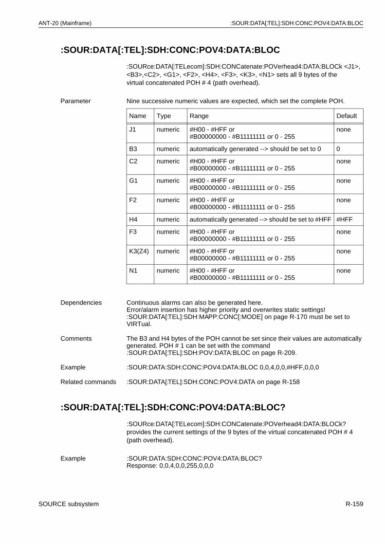
ANT-20 (Mainframe) :SOUR:DATA[:TEL]:SDH:CONC:POV4:DATA:BLOC
:SOUR:DATA[:TEL]:SDH:CONC:POV4:DATA:BLOC
:SOURce:DATA[:TELecom]:SDH:CONCatenate:POVerhead4:DATA:BLOCk <J1>, <B3>,<C2>, <G1>, <F2>, <H4>, <F3>, <K3>, <N1> sets all 9 bytes of thevirtual concatenated POH # 4 (path overhead).
:SOUR:DATA[:TEL]:SDH:CONC:POV4:DATA:BLOC?
:SOURce:DATA[:TELecom]:SDH:CONCatenate:POVerhead4:DATA:BLOCk? provides the current settings of the 9 bytes of the virtual concatenated POH # 4 (path overhead).
Parameter Nine successive numeric values are expected, which set the complete POH.
Name Type Range Default
J1 numeric #H00 - #HFF or#B00000000 - #B11111111 or 0 - 255
none
B3 numeric automatically generated --> should be set to 0 0
C2 numeric #H00 - #HFF or#B00000000 - #B11111111 or 0 - 255
none
G1 numeric #H00 - #HFF or#B00000000 - #B11111111 or 0 - 255
none
F2 numeric #H00 - #HFF or#B00000000 - #B11111111 or 0 - 255
none
H4 numeric automatically generated --> should be set to #HFF #HFF
F3 numeric #H00 - #HFF or#B00000000 - #B11111111 or 0 - 255
none
K3(Z4) numeric #H00 - #HFF or#B00000000 - #B11111111 or 0 - 255
none
N1 numeric #H00 - #HFF or#B00000000 - #B11111111 or 0 - 255
none
Dependencies Continuous alarms can also be generated here. Error/alarm insertion has higher priority and overwrites static settings! :SOUR:DATA[:TEL]:SDH:MAPP:CONC[:MODE] on page R-170 must be set to VIRTual.
Comments The B3 and H4 bytes of the POH cannot be set since their values are automatically generated. POH # 1 can be set with the command :SOUR:DATA[:TEL]:SDH:POV:DATA:BLOC on page R-209.
Example :SOUR:DATA:SDH:CONC:POV4:DATA:BLOC 0,0,4,0,0,#HFF,0,0,0
Related commands :SOUR:DATA[:TEL]:SDH:CONC:POV4:DATA on page R-158
Example :SOUR:DATA:SDH:CONC:POV4:DATA:BLOC?Response: 0,0,4,0,0,255,0,0,0
SOURCE subsystem R-159
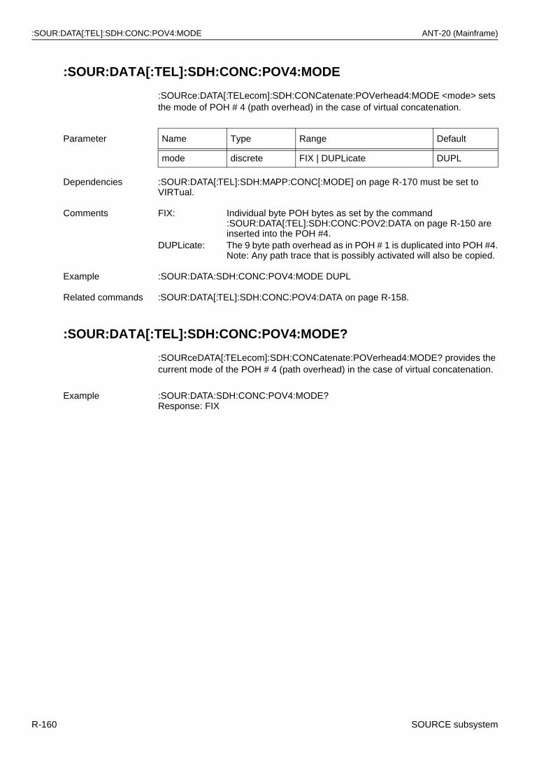
:SOUR:DATA[:TEL]:SDH:CONC:POV4:MODE ANT-20 (Mainframe)
:SOUR:DATA[:TEL]:SDH:CONC:POV4:MODE
:SOURce:DATA[:TELecom]:SDH:CONCatenate:POVerhead4:MODE <mode> sets the mode of POH # 4 (path overhead) in the case of virtual concatenation.
:SOUR:DATA[:TEL]:SDH:CONC:POV4:MODE?
:SOURceDATA[:TELecom]:SDH:CONCatenate:POVerhead4:MODE? provides the current mode of the POH # 4 (path overhead) in the case of virtual concatenation.
Parameter Name Type Range Default
mode discrete FIX | DUPLicate DUPL
Dependencies :SOUR:DATA[:TEL]:SDH:MAPP:CONC[:MODE] on page R-170 must be set to VIRTual.
Comments FIX: Individual byte POH bytes as set by the command :SOUR:DATA[:TEL]:SDH:CONC:POV2:DATA on page R-150 are inserted into the POH #4.
DUPLicate: The 9 byte path overhead as in POH # 1 is duplicated into POH #4.Note: Any path trace that is possibly activated will also be copied.
Example :SOUR:DATA:SDH:CONC:POV4:MODE DUPL
Related commands :SOUR:DATA[:TEL]:SDH:CONC:POV4:DATA on page R-158.
Example :SOUR:DATA:SDH:CONC:POV4:MODE?Response: FIX
R-160 SOURCE subsystem

ANT-20 (Mainframe) :SOUR:DATA[:TEL]:SDH:CONC:POV4:PRES
:SOUR:DATA[:TEL]:SDH:CONC:POV4:PRES
:SOURce:DATA[:TELecom]:SDH:CONCatenate:POVerhead4:PRESet sets thevirtual concatenated overhead bytes in POH # 4 to their default values.
Dependencies :SOUR:DATA[:TEL]:SDH:MAPP:CONC[:MODE] on page R-170 must be set to VIRTual.
Parameter None
Comments Standard overhead (hex):
POH bytes of POH # 1 - 4 Value
J1
B3
C2
G1
F2
H4
F3
K3(Z4)
N1
00
XX
02
00
00
YY
00
00
00
XX: Inserted via parity formation (B3)YY: Automatically filled through H4 sequence (H4).There is no query for this command.
Example :SOUR:DATA:SDH:CONC:POV4:PRES
Related commands None
SOURCE subsystem R-161
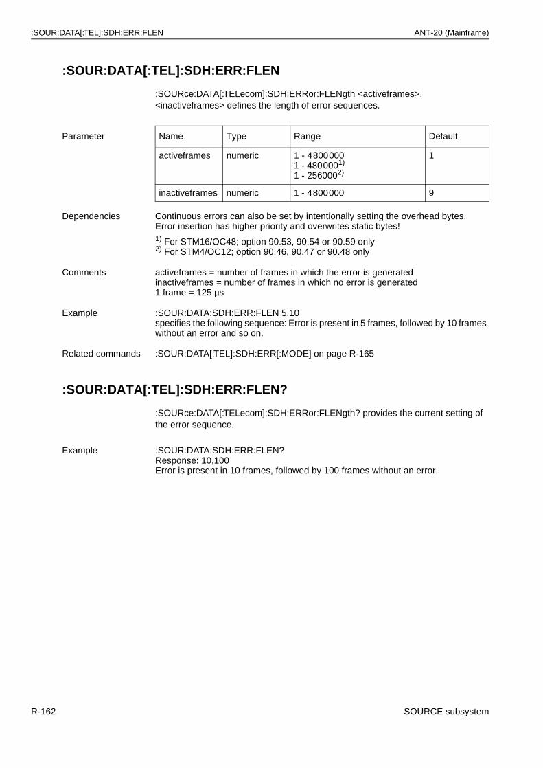
:SOUR:DATA[:TEL]:SDH:ERR:FLEN ANT-20 (Mainframe)
:SOUR:DATA[:TEL]:SDH:ERR:FLEN
:SOURce:DATA[:TELecom]:SDH:ERRor:FLENgth <activeframes>, <inactiveframes> defines the length of error sequences.
:SOUR:DATA[:TEL]:SDH:ERR:FLEN?
:SOURce:DATA[:TELecom]:SDH:ERRor:FLENgth? provides the current setting of the error sequence.
Parameter Name Type Range Default
activeframes numeric 1 - 48000001 - 4800001)
1 - 2560002)
1
inactiveframes numeric 1 - 4800000 9
Dependencies Continuous errors can also be set by intentionally setting the overhead bytes.Error insertion has higher priority and overwrites static bytes!1) For STM16/OC48; option 90.53, 90.54 or 90.59 only2) For STM4/OC12; option 90.46, 90.47 or 90.48 only
Comments activeframes = number of frames in which the error is generatedinactiveframes = number of frames in which no error is generated1 frame = 125 µs
Example :SOUR:DATA:SDH:ERR:FLEN 5,10specifies the following sequence: Error is present in 5 frames, followed by 10 frames without an error and so on.
Related commands :SOUR:DATA[:TEL]:SDH:ERR[:MODE] on page R-165
Example :SOUR:DATA:SDH:ERR:FLEN?Response: 10,100Error is present in 10 frames, followed by 100 frames without an error.
R-162 SOURCE subsystem
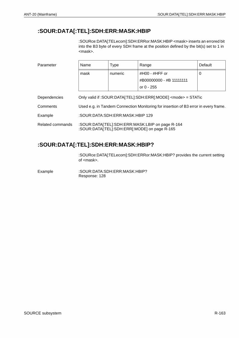
ANT-20 (Mainframe) :SOUR:DATA[:TEL]:SDH:ERR:MASK:HBIP
:SOUR:DATA[:TEL]:SDH:ERR:MASK:HBIP
:SOURce:DATA[:TELecom]:SDH:ERRor:MASK:HBIP <mask> inserts an errored bit into the B3 byte of every SDH frame at the position defined by the bit(s) set to 1 in <mask>.
:SOUR:DATA[:TEL]:SDH:ERR:MASK:HBIP?
:SOURce:DATA[:TELecom]:SDH:ERRor:MASK:HBIP? provides the current setting of <mask>.
Parameter Name Type Range Default
mask numeric #H00 - #HFF or
#B00000000 - #B 11111111
or 0 - 255
0
Dependencies Only valid if :SOUR:DATA[:TEL]:SDH:ERR[:MODE] <mode> = STATic
Comments Used e.g. in Tandem Connection Monitoring for insertion of B3 error in every frame.
Example :SOUR:DATA:SDH:ERR:MASK:HBIP 129
Related commands :SOUR:DATA[:TEL]:SDH:ERR:MASK:LBIP on page R-164:SOUR:DATA[:TEL]:SDH:ERR[:MODE] on page R-165
Example :SOUR:DATA:SDH:ERR:MASK:HBIP?Response: 128
SOURCE subsystem R-163
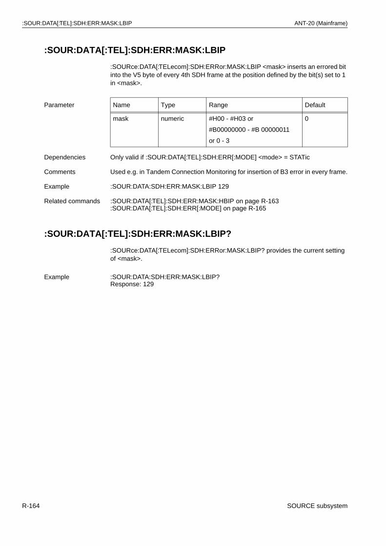
:SOUR:DATA[:TEL]:SDH:ERR:MASK:LBIP ANT-20 (Mainframe)
:SOUR:DATA[:TEL]:SDH:ERR:MASK:LBIP
:SOURce:DATA[:TELecom]:SDH:ERRor:MASK:LBIP <mask> inserts an errored bit into the V5 byte of every 4th SDH frame at the position defined by the bit(s) set to 1 in <mask>.
:SOUR:DATA[:TEL]:SDH:ERR:MASK:LBIP?
:SOURce:DATA[:TELecom]:SDH:ERRor:MASK:LBIP? provides the current setting of <mask>.
Parameter Name Type Range Default
mask numeric #H00 - #H03 or
#B00000000 - #B 00000011
or 0 - 3
0
Dependencies Only valid if :SOUR:DATA[:TEL]:SDH:ERR[:MODE] <mode> = STATic
Comments Used e.g. in Tandem Connection Monitoring for insertion of B3 error in every frame.
Example :SOUR:DATA:SDH:ERR:MASK:LBIP 129
Related commands :SOUR:DATA[:TEL]:SDH:ERR:MASK:HBIP on page R-163:SOUR:DATA[:TEL]:SDH:ERR[:MODE] on page R-165
Example :SOUR:DATA:SDH:ERR:MASK:LBIP?Response: 129
R-164 SOURCE subsystem
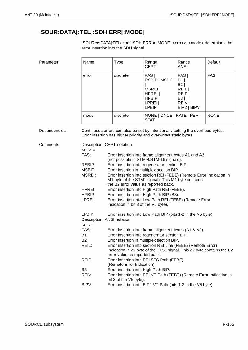
ANT-20 (Mainframe) :SOUR:DATA[:TEL]:SDH:ERR[:MODE]
:SOUR:DATA[:TEL]:SDH:ERR[:MODE]
:SOURce:DATA[:TELecom]:SDH:ERRor[:MODE] <error>, <mode> determines the error insertion into the SDH signal.
Parameter Name Type RangeCEPT
RangeANSI
Default
error discrete FAS | RSBIP | MSBIP | MSREI | HPREI |HPBIP |LPREI |LPBIP
FAS |B1 |B2 |REIL |REIP | B3 | REIV | BIP2 | BIPV
FAS
mode discrete NONE | ONCE | RATE | PER | STAT
NONE
Dependencies Continuous errors can also be set by intentionally setting the overhead bytes.Error insertion has higher priority and overwrites static bytes!
Comments Description: CEPT notation<err> =FAS: Error insertion into frame alignment bytes A1 and A2
(not possible in STM-4/STM-16 signals).RSBIP: Error insertion into regenerator section BIP.MSBIP: Error insertion in multiplex section BIP.MSREI: Error insertion into section REI (FEBE) (Remote Error Indication in
M1 byte of the STM1 signal). This M1 byte containsthe B2 error value as reported back.
HPREI: Error insertion into High Path REI (FEBE).HPBIP: Error insertion into High Path BIP (B3).LPREI: Error insertion into Low Path REI (FEBE) (Remote Error
Indication in bit 3 of the V5 byte).
LPBIP: Error insertion into Low Path BIP (bits 1-2 in the V5 byte)Description: ANSI notation<err> =FAS: Error insertion into frame alignment bytes (A1 & A2).B1: Error insertion into regenerator section BIP.B2: Error insertion in multiplex section BIP.REIL: Error insertion into section REI Line (FEBE) (Remote Error)
Indication in Z2 byte of the STS1 signal. This Z2 byte contains the B2 error value as reported back.
REIP: Error insertion into REI STS Path (FEBE)(Remote Error Indication).
B3: Error insertion into High Path BIP.REIV: Error insertion into REI VT-Path (FEBE) (Remote Error Indication in
bit 3 of the V5 byte).BIPV: Error insertion into BIP2 VT-Path (bits 1-2 in the V5 byte).
SOURCE subsystem R-165
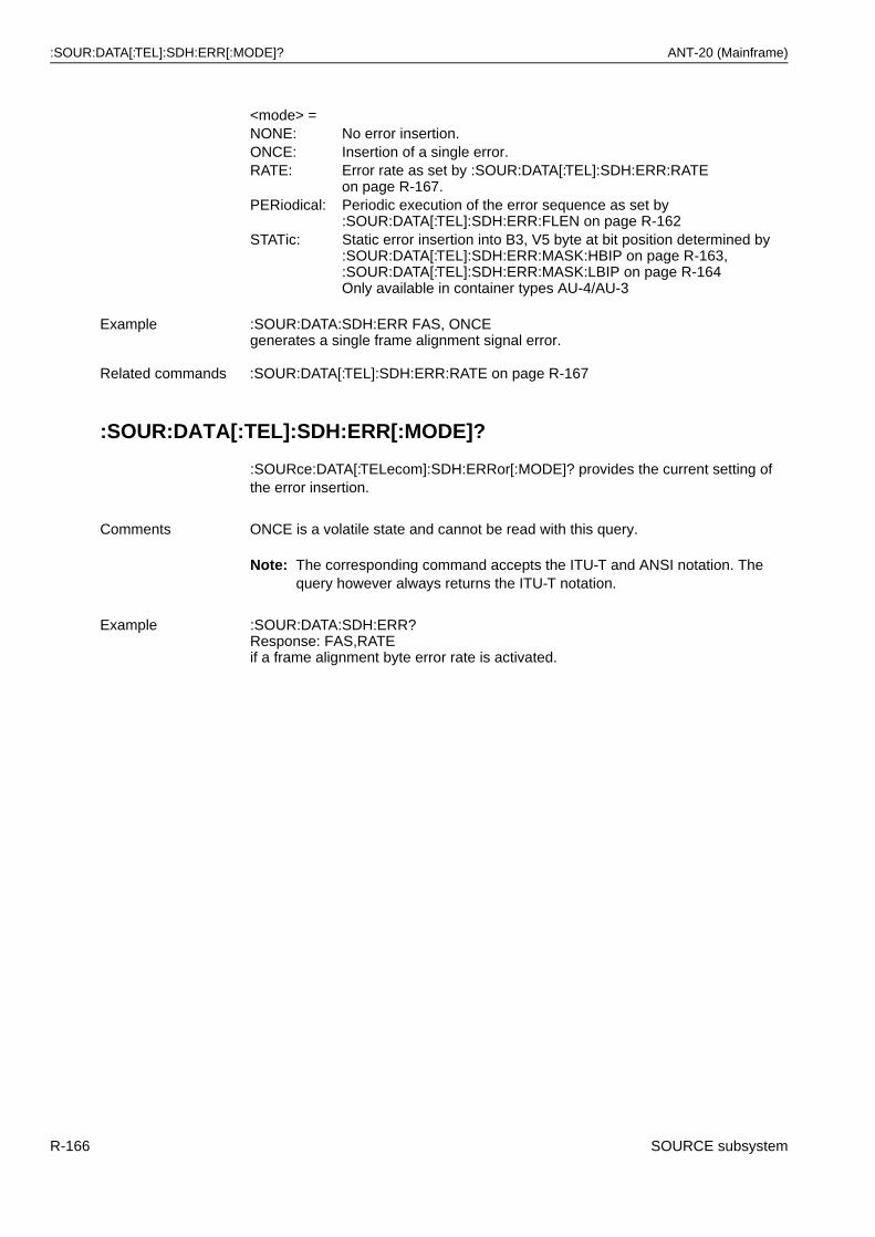
:SOUR:DATA[:TEL]:SDH:ERR[:MODE]? ANT-20 (Mainframe)
:SOUR:DATA[:TEL]:SDH:ERR[:MODE]?
:SOURce:DATA[:TELecom]:SDH:ERRor[:MODE]? provides the current setting of the error insertion.
Note: The corresponding command accepts the ITU-T and ANSI notation. The query however always returns the ITU-T notation.
<mode> =NONE: No error insertion.ONCE: Insertion of a single error.RATE: Error rate as set by :SOUR:DATA[:TEL]:SDH:ERR:RATE
on page R-167.PERiodical: Periodic execution of the error sequence as set by
:SOUR:DATA[:TEL]:SDH:ERR:FLEN on page R-162STATic: Static error insertion into B3, V5 byte at bit position determined by
:SOUR:DATA[:TEL]:SDH:ERR:MASK:HBIP on page R-163, :SOUR:DATA[:TEL]:SDH:ERR:MASK:LBIP on page R-164Only available in container types AU-4/AU-3
Example :SOUR:DATA:SDH:ERR FAS, ONCEgenerates a single frame alignment signal error.
Related commands :SOUR:DATA[:TEL]:SDH:ERR:RATE on page R-167
Comments ONCE is a volatile state and cannot be read with this query.
Example :SOUR:DATA:SDH:ERR?Response: FAS,RATEif a frame alignment byte error rate is activated.
R-166 SOURCE subsystem
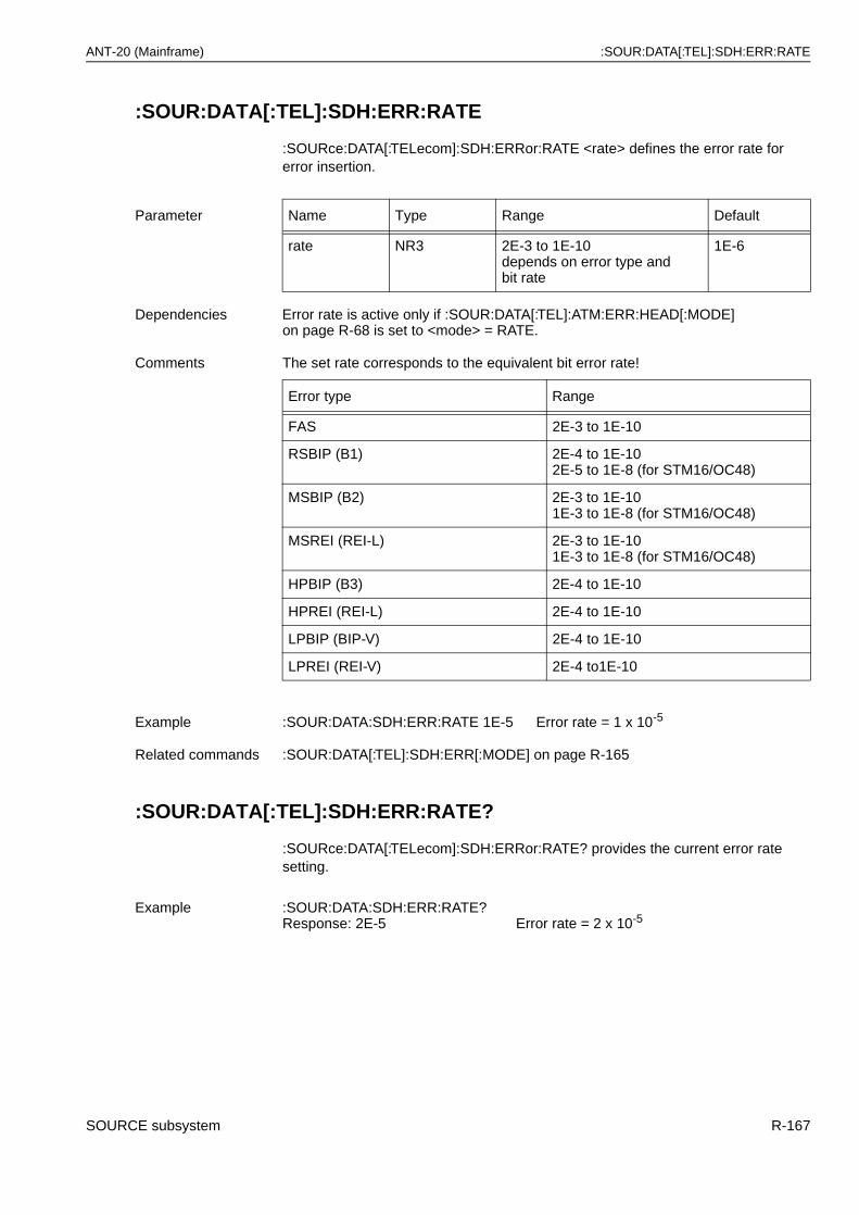
ANT-20 (Mainframe) :SOUR:DATA[:TEL]:SDH:ERR:RATE
:SOUR:DATA[:TEL]:SDH:ERR:RATE
:SOURce:DATA[:TELecom]:SDH:ERRor:RATE <rate> defines the error rate for error insertion.
:SOUR:DATA[:TEL]:SDH:ERR:RATE?
:SOURce:DATA[:TELecom]:SDH:ERRor:RATE? provides the current error rate setting.
Parameter Name Type Range Default
rate NR3 2E-3 to 1E-10depends on error type and bit rate
1E-6
Dependencies Error rate is active only if :SOUR:DATA[:TEL]:ATM:ERR:HEAD[:MODE] on page R-68 is set to <mode> = RATE.
Comments The set rate corresponds to the equivalent bit error rate!
Error type Range
FAS 2E-3 to 1E-10
RSBIP (B1) 2E-4 to 1E-102E-5 to 1E-8 (for STM16/OC48)
MSBIP (B2) 2E-3 to 1E-101E-3 to 1E-8 (for STM16/OC48)
MSREI (REI-L) 2E-3 to 1E-101E-3 to 1E-8 (for STM16/OC48)
HPBIP (B3) 2E-4 to 1E-10
HPREI (REI-L) 2E-4 to 1E-10
LPBIP (BIP-V) 2E-4 to 1E-10
LPREI (REI-V) 2E-4 to1E-10
Example :SOUR:DATA:SDH:ERR:RATE 1E-5 Error rate = 1 x 10⁻⁵
Related commands :SOUR:DATA[:TEL]:SDH:ERR[:MODE] on page R-165
Example :SOUR:DATA:SDH:ERR:RATE?Response: 2E-5 Error rate = 2 x 10⁻⁵
SOURCE subsystem R-167
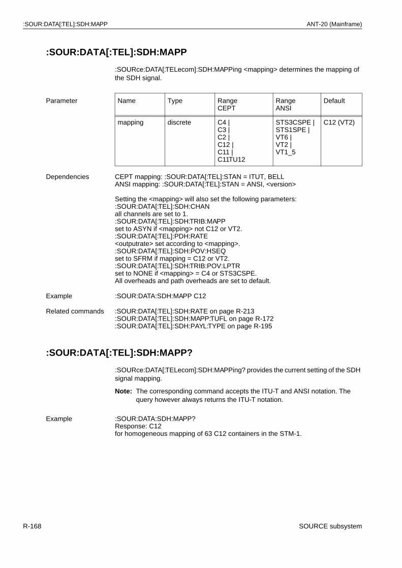
:SOUR:DATA[:TEL]:SDH:MAPP ANT-20 (Mainframe)
:SOUR:DATA[:TEL]:SDH:MAPP
:SOURce:DATA[:TELecom]:SDH:MAPPing <mapping> determines the mapping of the SDH signal.
:SOUR:DATA[:TEL]:SDH:MAPP?
:SOURce:DATA[:TELecom]:SDH:MAPPing? provides the current setting of the SDH signal mapping.
Note: The corresponding command accepts the ITU-T and ANSI notation. The query however always returns the ITU-T notation.
Parameter Name Type RangeCEPT
RangeANSI
Default
mapping discrete C4 |C3 |C2 |C12 |C11 |C11TU12
STS3CSPE |STS1SPE |VT6 |VT2 |VT1_5
C12 (VT2)
Dependencies CEPT mapping: :SOUR:DATA[:TEL]:STAN = ITUT, BELLANSI mapping: :SOUR:DATA[:TEL]:STAN = ANSI, <version>
Setting the <mapping> will also set the following parameters::SOUR:DATA[:TEL]:SDH:CHANall channels are set to 1.:SOUR:DATA[:TEL]:SDH:TRIB:MAPPset to ASYN if <mapping> not C12 or VT2.:SOUR:DATA[:TEL]:PDH:RATE<outputrate> set according to <mapping>.:SOUR:DATA[:TEL]:SDH:POV:HSEQset to SFRM if mapping = C12 or VT2.:SOUR:DATA[:TEL]:SDH:TRIB:POV:LPTRset to NONE if <mapping> = C4 or STS3CSPE.All overheads and path overheads are set to default.
Example :SOUR:DATA:SDH:MAPP C12
Related commands :SOUR:DATA[:TEL]:SDH:RATE on page R-213:SOUR:DATA[:TEL]:SDH:MAPP:TUFL on page R-172:SOUR:DATA[:TEL]:SDH:PAYL:TYPE on page R-195
Example :SOUR:DATA:SDH:MAPP?Response: C12for homogeneous mapping of 63 C12 containers in the STM-1.
R-168 SOURCE subsystem
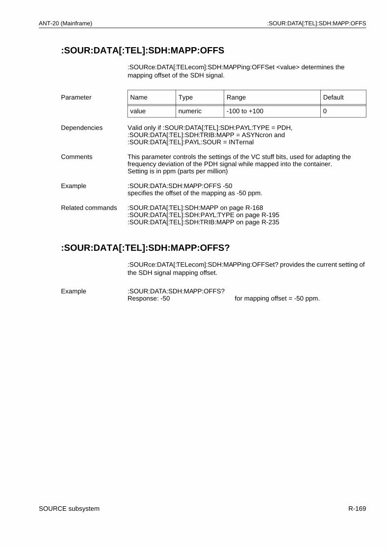
ANT-20 (Mainframe) :SOUR:DATA[:TEL]:SDH:MAPP:OFFS
:SOUR:DATA[:TEL]:SDH:MAPP:OFFS
:SOURce:DATA[:TELecom]:SDH:MAPPing:OFFSet <value> determines the mapping offset of the SDH signal.
:SOUR:DATA[:TEL]:SDH:MAPP:OFFS?
:SOURce:DATA[:TELecom]:SDH:MAPPing:OFFSet? provides the current setting of the SDH signal mapping offset.
Parameter Name Type Range Default
value numeric -100 to +100 0
Dependencies Valid only if :SOUR:DATA[:TEL]:SDH:PAYL:TYPE = PDH, :SOUR:DATA[:TEL]:SDH:TRIB:MAPP = ASYNcron and :SOUR:DATA[:TEL]:PAYL:SOUR = INTernal
Comments This parameter controls the settings of the VC stuff bits, used for adapting the frequency deviation of the PDH signal while mapped into the container. Setting is in ppm (parts per million)
Example :SOUR:DATA:SDH:MAPP:OFFS -50specifies the offset of the mapping as -50 ppm.
Related commands :SOUR:DATA[:TEL]:SDH:MAPP on page R-168:SOUR:DATA[:TEL]:SDH:PAYL:TYPE on page R-195:SOUR:DATA[:TEL]:SDH:TRIB:MAPP on page R-235
Example :SOUR:DATA:SDH:MAPP:OFFS?Response: -50 for mapping offset = -50 ppm.
SOURCE subsystem R-169
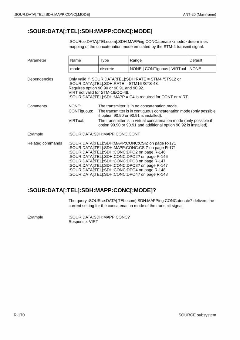
:SOUR:DATA[:TEL]:SDH:MAPP:CONC[:MODE] ANT-20 (Mainframe)
:SOUR:DATA[:TEL]:SDH:MAPP:CONC[:MODE]
:SOURce:DATA[:TELecom]:SDH:MAPPing:CONCatenate <mode> determines mapping of the concatenation mode emulated by the STM-4 transmit signal.
:SOUR:DATA[:TEL]:SDH:MAPP:CONC[:MODE]?
The query :SOURce:DATA[:TELecom]:SDH:MAPPing:CONCatenate? delivers the current setting for the concatenation mode of the transmit signal.
Parameter Name Type Range Default
mode discrete NONE | CONTiguous | VIRTual NONE
Dependencies Only valid if :SOUR:DATA[:TEL]:SDH:RATE = STM4 /STS12 or :SOUR:DATA[:TEL]:SDH:RATE = STM16 /STS-48. Requires option 90.90 or 90.91 and 90.92. VIRT not valid for STM-16/OC-48. :SOUR:DATA[:TEL]:SDH:MAPP = C4 is required for CONT or VIRT.
Comments NONE: The transmitter is in no concatenation mode.CONTiguous: The transmitter is in contiguous concatenation mode (only possible
if option 90.90 or 90.91 is installed).VIRTual: The transmitter is in virtual concatenation mode (only possible if
option 90.90 or 90.91 and additional option 90.92 is installed).
Example :SOUR:DATA:SDH:MAPP:CONC CONT
Related commands :SOUR:DATA[:TEL]:SDH:MAPP:CONC:CSIZ on page R-171:SOUR:DATA[:TEL]:SDH:MAPP:CONC:CSIZ on page R-171:SOUR:DATA[:TEL]:SDH:CONC:DPO2 on page R-146:SOUR:DATA[:TEL]:SDH:CONC:DPO2? on page R-146:SOUR:DATA[:TEL]:SDH:CONC:DPO3 on page R-147:SOUR:DATA[:TEL]:SDH:CONC:DPO3? on page R-147:SOUR:DATA[:TEL]:SDH:CONC:DPO4 on page R-148:SOUR:DATA[:TEL]:SDH:CONC:DPO4? on page R-148
Example :SOUR:DATA:SDH:MAPP:CONC?Response: VIRT
R-170 SOURCE subsystem
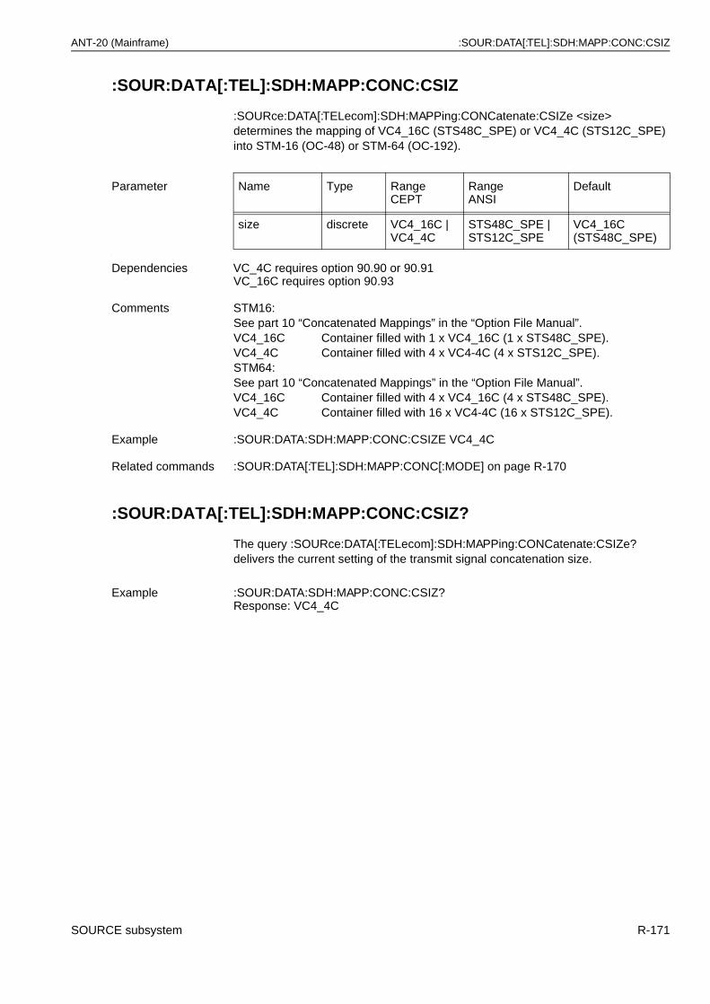
ANT-20 (Mainframe) :SOUR:DATA[:TEL]:SDH:MAPP:CONC:CSIZ
:SOUR:DATA[:TEL]:SDH:MAPP:CONC:CSIZ
:SOURce:DATA[:TELecom]:SDH:MAPPing:CONCatenate:CSIZe <size> determines the mapping of VC4_16C (STS48C_SPE) or VC4_4C (STS12C_SPE) into STM-16 (OC-48) or STM-64 (OC-192).
.
:SOUR:DATA[:TEL]:SDH:MAPP:CONC:CSIZ?
The query :SOURce:DATA[:TELecom]:SDH:MAPPing:CONCatenate:CSIZe? delivers the current setting of the transmit signal concatenation size.
Parameter Name Type RangeCEPT
RangeANSI
Default
size discrete VC4_16C |VC4_4C
STS48C_SPE | STS12C_SPE
VC4_16C (STS48C_SPE)
Dependencies VC_4C requires option 90.90 or 90.91VC_16C requires option 90.93
Comments STM16:See part 10 “Concatenated Mappings” in the “Option File Manual”.VC4_16C Container filled with 1 x VC4_16C (1 x STS48C_SPE).VC4_4C Container filled with 4 x VC4-4C (4 x STS12C_SPE).STM64:See part 10 “Concatenated Mappings” in the “Option File Manual”.VC4_16C Container filled with 4 x VC4_16C (4 x STS48C_SPE).VC4_4C Container filled with 16 x VC4-4C (16 x STS12C_SPE).
Example :SOUR:DATA:SDH:MAPP:CONC:CSIZE VC4_4C
Related commands :SOUR:DATA[:TEL]:SDH:MAPP:CONC[:MODE] on page R-170
Example :SOUR:DATA:SDH:MAPP:CONC:CSIZ?Response: VC4_4C
SOURCE subsystem R-171
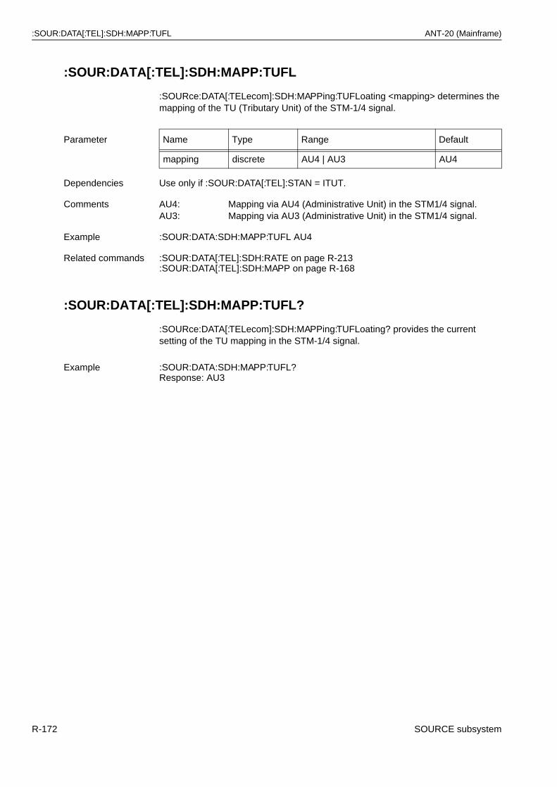
:SOUR:DATA[:TEL]:SDH:MAPP:TUFL ANT-20 (Mainframe)
:SOUR:DATA[:TEL]:SDH:MAPP:TUFL
:SOURce:DATA[:TELecom]:SDH:MAPPing:TUFLoating <mapping> determines the mapping of the TU (Tributary Unit) of the STM-1/4 signal.
:SOUR:DATA[:TEL]:SDH:MAPP:TUFL?
:SOURce:DATA[:TELecom]:SDH:MAPPing:TUFLoating? provides the current setting of the TU mapping in the STM-1/4 signal.
Parameter Name Type Range Default
mapping discrete AU4 | AU3 AU4
Dependencies Use only if :SOUR:DATA[:TEL]:STAN = ITUT.
Comments AU4: Mapping via AU4 (Administrative Unit) in the STM1/4 signal.AU3: Mapping via AU3 (Administrative Unit) in the STM1/4 signal.
Example :SOUR:DATA:SDH:MAPP:TUFL AU4
Related commands :SOUR:DATA[:TEL]:SDH:RATE on page R-213:SOUR:DATA[:TEL]:SDH:MAPP on page R-168
Example :SOUR:DATA:SDH:MAPP:TUFL?Response: AU3
R-172 SOURCE subsystem
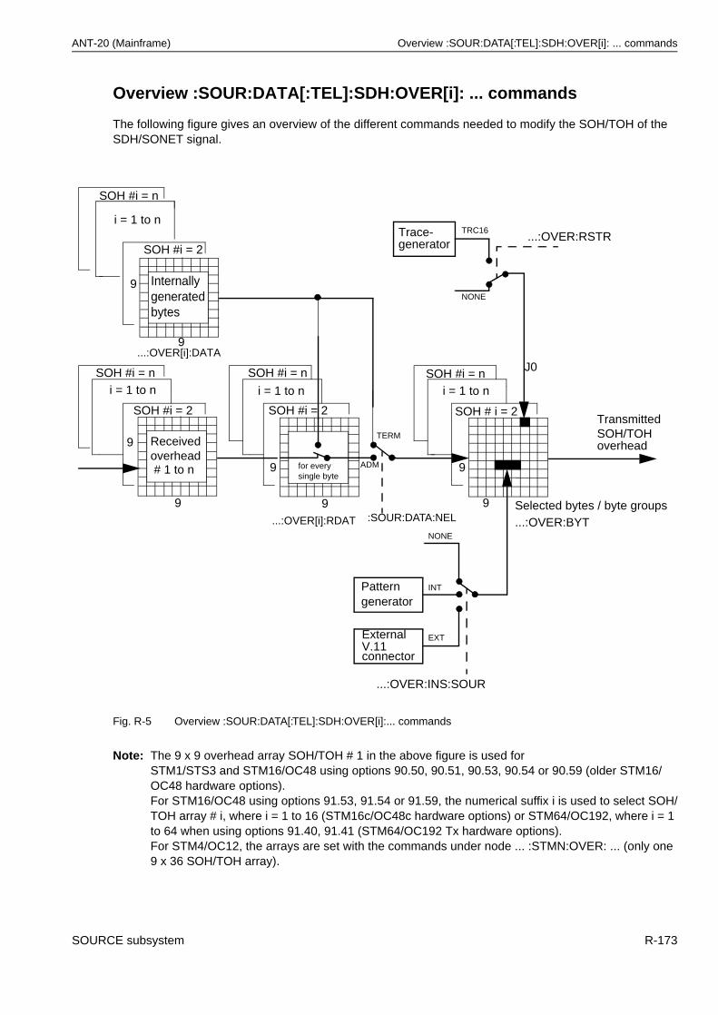
ANT-20 (Mainframe) Overview :SOUR:DATA[:TEL]:SDH:OVER[i]: ... commands
Overview :SOUR:DATA[:TEL]:SDH:OVER[i]: ... commands
The following figure gives an overview of the different commands needed to modify the SOH/TOH of the SDH/SONET signal.
Fig. R-5 Overview :SOUR:DATA[:TEL]:SDH:OVER[i]:... commands
Note: The 9 x 9 overhead array SOH/TOH # 1 in the above figure is used for STM1/STS3 and STM16/OC48 using options 90.50, 90.51, 90.53, 90.54 or 90.59 (older STM16/OC48 hardware options).For STM16/OC48 using options 91.53, 91.54 or 91.59, the numerical suffix i is used to select SOH/TOH array # i, where i = 1 to 16 (STM16c/OC48c hardware options) or STM64/OC192, where i = 1 to 64 when using options 91.40, 91.41 (STM64/OC192 Tx hardware options).For STM4/OC12, the arrays are set with the commands under node ... :STMN:OVER: ... (only one 9 x 36 SOH/TOH array).
9
9
9
9
9
9 Receivedoverhead
...:OVER[i]:DATA
...:OVER[i]:RDAT
Internallygeneratedbytes
9
9
Patterngenerator
ExternalV.11connector
NONE
INT
EXT
...:OVER:INS:SOUR
Selected bytes / byte groups...:OVER:BYT
NONE
TRC16Trace-generator
...:OVER:RSTR
TransmittedSOH/TOH
J0
:SOUR:DATA:NEL
ADM
TERM
for everysingle byte
overhead
i = 1 to n
SOH #i = n
SOH #i = 2
SOH #i = 2
# 1 to n
SOH #i = ni = 1 to n
SOH #i = n
SOH #i = 2 SOH # i = 2
i = 1 to nSOH #i = n
i = 1 to n
SOURCE subsystem R-173
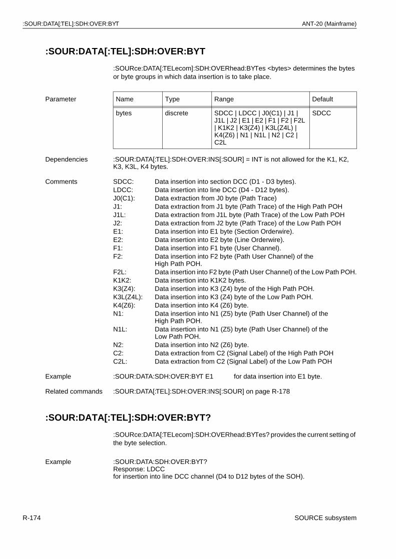
:SOUR:DATA[:TEL]:SDH:OVER:BYT ANT-20 (Mainframe)
:SOUR:DATA[:TEL]:SDH:OVER:BYT
:SOURce:DATA[:TELecom]:SDH:OVERhead:BYTes <bytes> determines the bytes or byte groups in which data insertion is to take place.
:SOUR:DATA[:TEL]:SDH:OVER:BYT?
:SOURce:DATA[:TELecom]:SDH:OVERhead:BYTes? provides the current setting of the byte selection.
Parameter Name Type Range Default
bytes discrete SDCC | LDCC | J0(C1) | J1 | J1L | J2 | E1 | E2 | F1 | F2 | F2L | K1K2 | K3(Z4) | K3L(Z4L) | K4(Z6) | N1 | N1L | N2 | C2 | C2L
SDCC
Dependencies :SOUR:DATA[:TEL]:SDH:OVER:INS[:SOUR] = INT is not allowed for the K1, K2, K3, K3L, K4 bytes.
Comments SDCC: Data insertion into section DCC (D1 - D3 bytes).LDCC: Data insertion into line DCC (D4 - D12 bytes).J0(C1): Data extraction from J0 byte (Path Trace)J1: Data extraction from J1 byte (Path Trace) of the High Path POHJ1L: Data extraction from J1L byte (Path Trace) of the Low Path POHJ2: Data extraction from J2 byte (Path Trace) of the Low Path POHE1: Data insertion into E1 byte (Section Orderwire).E2: Data insertion into E2 byte (Line Orderwire).F1: Data insertion into F1 byte (User Channel).F2: Data insertion into F2 byte (Path User Channel) of the
High Path POH.F2L: Data insertion into F2 byte (Path User Channel) of the Low Path POH.K1K2: Data insertion into K1K2 bytes.K3(Z4): Data insertion into K3 (Z4) byte of the High Path POH.K3L(Z4L): Data insertion into K3 (Z4) byte of the Low Path POH.K4(Z6): Data insertion into K4 (Z6) byte.N1: Data insertion into N1 (Z5) byte (Path User Channel) of the
High Path POH.N1L: Data insertion into N1 (Z5) byte (Path User Channel) of the
Low Path POH.N2: Data insertion into N2 (Z6) byte.C2: Data extraction from C2 (Signal Label) of the High Path POHC2L: Data extraction from C2 (Signal Label) of the Low Path POH
Example :SOUR:DATA:SDH:OVER:BYT E1 for data insertion into E1 byte.
Related commands :SOUR:DATA[:TEL]:SDH:OVER:INS[:SOUR] on page R-178
Example :SOUR:DATA:SDH:OVER:BYT?Response: LDCCfor insertion into line DCC channel (D4 to D12 bytes of the SOH).
R-174 SOURCE subsystem
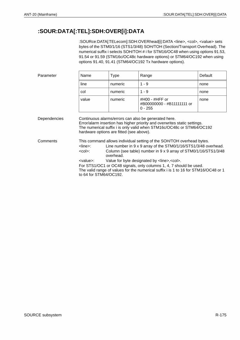
ANT-20 (Mainframe) :SOUR:DATA[:TEL]:SDH:OVER[i]:DATA
:SOUR:DATA[:TEL]:SDH:OVER[i]:DATA
:SOURce:DATA[:TELecom]:SDH:OVERhead[i]:DATA <line>, <col>, <value> sets bytes of the STM0/1/16 (STS1/3/48) SOH/TOH (Section/Transport Overhead). The numerical suffix i selects SOH/TOH # i for STM16/OC48 when using options 91.53, 91.54 or 91.59 (STM16c/OC48c hardware options) or STM64/OC192 when using options 91.40, 91.41 (STM64/OC192 Tx hardware options).
Parameter Name Type Range Default
line numeric 1 - 9 none
col numeric 1 - 9 none
value numeric #H00 - #HFF or#B00000000 - #B11111111 or 0 - 255
none
Dependencies Continuous alarms/errors can also be generated here.Error/alarm insertion has higher priority and overwrites static settings.The numerical suffix i is only valid when STM16c/OC48c or STM64/OC192 hardware options are fitted (see above).
Comments This command allows individual setting of the SOH/TOH overhead bytes.<line>: Line number in 9 x 9 array of the STM0/1/16/STS1/3/48 overhead.<col>: Column (see table) number in 9 x 9 array of STM0/1/16/STS1/3/48
overhead.<value>: Value for byte designated by <line>,<col>.For STS1/OC1 or OC48 signals, only columns 1, 4, 7 should be used.The valid range of values for the numerical suffix i is 1 to 16 for STM16/OC48 or 1 to 64 for STM64/OC192.
SOURCE subsystem R-175
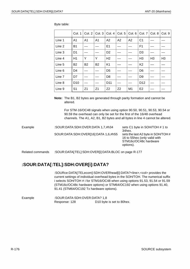
:SOUR:DATA[:TEL]:SDH:OVER[i]:DATA? ANT-20 (Mainframe)
Byte table:
Note: The B1, B2 bytes are generated through parity formation and cannot be altered.
For STM-16/OC48 signals when using option 90.50, 90.51, 90.53, 90.54 or 90.59 the overhead can only be set for the first of the 16/48 overhead channels. The A1, A2, B1, B2 bytes and all bytes in line 4 cannot be altered.
:SOUR:DATA[:TEL]:SDH:OVER[i]:DATA?
:SOURce:DATA[:TELecom]:SDH:OVERhead[i]:DATA?<line>,<col> provides the current settings of individual overhead bytes in the SOH/TOH. The numerical suffix i selects SOH/TOH # i for STM16/OC48 when using options 91.53, 91.54 or 91.59 (STM16c/OC48c hardware options) or STM64/OC192 when using options 91.40, 91.41 (STM64/OC192 Tx hardware options).
Col. 1 Col. 2 Col. 3 Col. 4 Col. 5 Col. 6 Col. 7 Col. 8 Col. 9
Line 1 A1 A1 A1 A2 A2 A2 C1 –– ––
Line 2 B1 –– –– E1 –– –– F1 –– ––
Line 3 D1 –– –– D2 –– –– D3 –– ––
Line 4 H1 Y Y H2 –– –– H3 H3 H3
Line 5 B2 B2 B2 K1 –– –– K2 –– ––
Line 6 D4 –– –– D5 –– –– D6 –– ––
Line 7 D7 –– –– D8 –– –– D9 –– ––
Line 8 D10 –– –– D11 –– –– D12 –– ––
Line 9 S1 Z1 Z1 Z2 Z2 M1 E2 –– ––
Example :SOUR:DATA:SDH:OVER:DATA 1,7,#h34
SOUR:DATA:SDH:OVER[16]:DATA 1,6,#h55
sets C1 byte in SOH/TOH # 1 to 34hex.sets the last A2 byte in SOH/TOH # 16 to 55hex (only valid with STM16c/OC48c hardware options).
Related commands :SOUR:DATA[:TEL]:SDH:OVER[i]:DATA:BLOC on page R-177
Example :SOUR:DATA:SDH:OVER:DATA? 1,8Response: 128 D10 byte is set to 80hex.
R-176 SOURCE subsystem
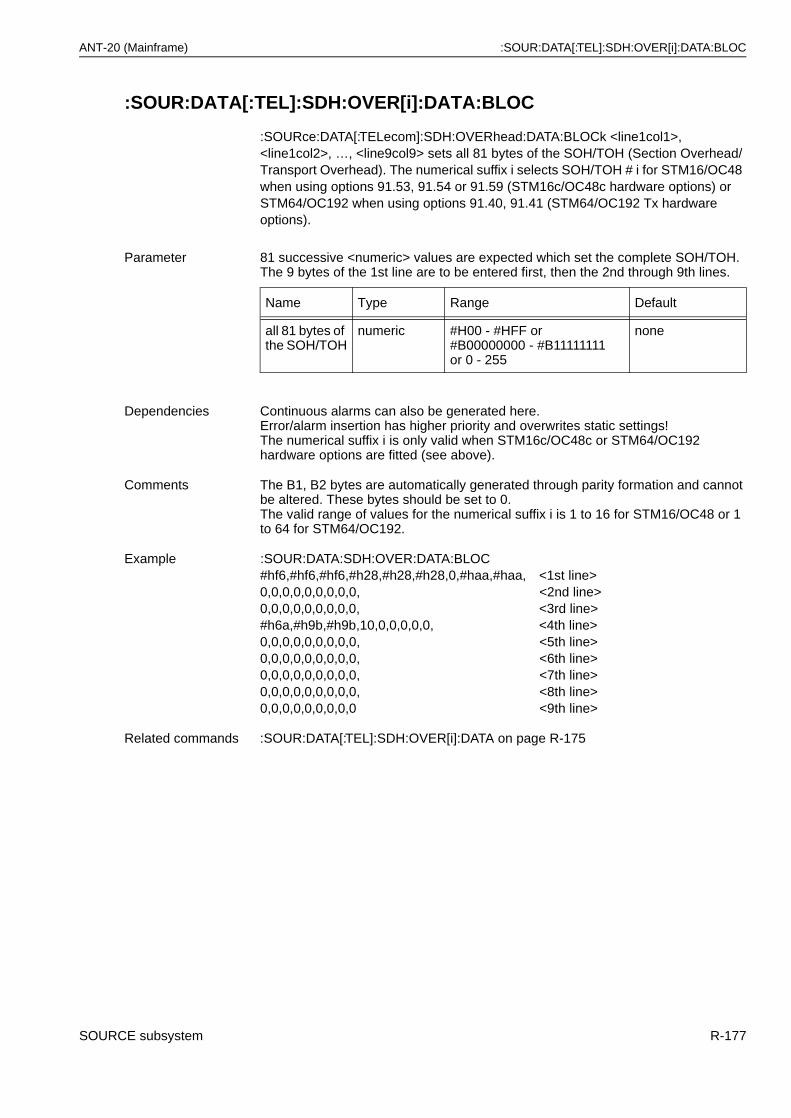
ANT-20 (Mainframe) :SOUR:DATA[:TEL]:SDH:OVER[i]:DATA:BLOC
:SOUR:DATA[:TEL]:SDH:OVER[i]:DATA:BLOC
:SOURce:DATA[:TELecom]:SDH:OVERhead:DATA:BLOCk <line1col1>, <line1col2>, …, <line9col9> sets all 81 bytes of the SOH/TOH (Section Overhead/Transport Overhead). The numerical suffix i selects SOH/TOH # i for STM16/OC48 when using options 91.53, 91.54 or 91.59 (STM16c/OC48c hardware options) or STM64/OC192 when using options 91.40, 91.41 (STM64/OC192 Tx hardware options).
Parameter 81 successive <numeric> values are expected which set the complete SOH/TOH. The 9 bytes of the 1st line are to be entered first, then the 2nd through 9th lines.
Name Type Range Default
all 81 bytes of the SOH/TOH
numeric #H00 - #HFF or#B00000000 - #B11111111 or 0 - 255
none
Dependencies Continuous alarms can also be generated here.Error/alarm insertion has higher priority and overwrites static settings!The numerical suffix i is only valid when STM16c/OC48c or STM64/OC192 hardware options are fitted (see above).
Comments The B1, B2 bytes are automatically generated through parity formation and cannot be altered. These bytes should be set to 0.The valid range of values for the numerical suffix i is 1 to 16 for STM16/OC48 or 1 to 64 for STM64/OC192.
Example :SOUR:DATA:SDH:OVER:DATA:BLOC#hf6,#hf6,#hf6,#h28,#h28,#h28,0,#haa,#haa, <1st line>0,0,0,0,0,0,0,0,0, <2nd line>0,0,0,0,0,0,0,0,0, <3rd line>#h6a,#h9b,#h9b,10,0,0,0,0,0, <4th line>0,0,0,0,0,0,0,0,0, <5th line>0,0,0,0,0,0,0,0,0, <6th line>0,0,0,0,0,0,0,0,0, <7th line>0,0,0,0,0,0,0,0,0, <8th line>0,0,0,0,0,0,0,0,0 <9th line>
Related commands :SOUR:DATA[:TEL]:SDH:OVER[i]:DATA on page R-175
SOURCE subsystem R-177
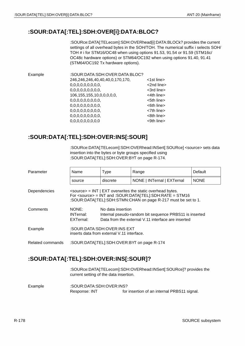
:SOUR:DATA[:TEL]:SDH:OVER[i]:DATA:BLOC? ANT-20 (Mainframe)
:SOUR:DATA[:TEL]:SDH:OVER[i]:DATA:BLOC?
:SOURce:DATA[:TELecom]:SDH:OVERhead[i]:DATA:BLOCk? provides the current settings of all overhead bytes in the SOH/TOH. The numerical suffix i selects SOH/TOH # i for STM16/OC48 when using options 91.53, 91.54 or 91.59 (STM16c/OC48c hardware options) or STM64/OC192 when using options 91.40, 91.41 (STM64/OC192 Tx hardware options).
:SOUR:DATA[:TEL]:SDH:OVER:INS[:SOUR]
:SOURce:DATA[:TELecom]:SDH:OVERhead:INSert[:SOURce] <source> sets data insertion into the bytes or byte groups specified using :SOUR:DATA[:TEL]:SDH:OVER:BYT on page R-174.
:SOUR:DATA[:TEL]:SDH:OVER:INS[:SOUR]?
:SOURce:DATA[:TELecom]:SDH:OVERhead:INSert[:SOURce]? provides the current setting of the data insertion.
Example :SOUR:DATA:SDH:OVER:DATA:BLOC?246,246,246,40,40,40,0,170,170, <1st line>0,0,0,0,0,0,0,0,0, <2nd line>0,0,0,0,0,0,0,0,0, <3rd line>106,155,155,10,0,0,0,0,0, <4th line>0,0,0,0,0,0,0,0,0, <5th line>0,0,0,0,0,0,0,0,0, <6th line>0,0,0,0,0,0,0,0,0, <7th line>0,0,0,0,0,0,0,0,0, <8th line>0,0,0,0,0,0,0,0,0 <9th line>
Parameter Name Type Range Default
source discrete NONE | INTernal | EXTernal NONE
Dependencies <source> = INT | EXT overwrites the static overhead bytes.For <source> = INT and :SOUR:DATA[:TEL]:SDH:RATE = STM16 :SOUR:DATA[:TEL]:SDH:STMN:CHAN on page R-217 must be set to 1.
Comments NONE: No data insertionINTernal: Internal pseudo-random bit sequence PRBS11 is insertedEXTernal: Data from the external V.11 interface are inserted
Example :SOUR:DATA:SDH:OVER:INS EXTinserts data from external V.11 interface.
Related commands :SOUR:DATA[:TEL]:SDH:OVER:BYT on page R-174
Example :SOUR:DATA:SDH:OVER:INS?Response: INT for insertion of an internal PRBS11 signal.
R-178 SOURCE subsystem
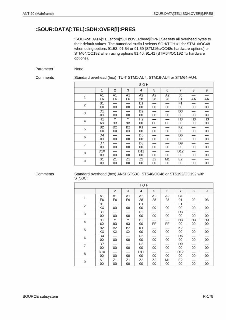
ANT-20 (Mainframe) :SOUR:DATA[:TEL]:SDH:OVER[i]:PRES
:SOUR:DATA[:TEL]:SDH:OVER[i]:PRES
:SOURce:DATA[:TELecom]:SDH:OVERhead[i]:PRESet sets all overhead bytes to their default values. The numerical suffix i selects SOH/TOH # i for STM16/OC48 when using options 91.53, 91.54 or 91.59 (STM16c/OC48c hardware options) or STM64/OC192 when using options 91.40, 91.41 (STM64/OC192 Tx hardware options).
Parameter None
Comments Standard overhead (hex) ITU-T STM1-AU4, STM16-AU4 or STM64-AU4:
S O H
1 2 3 4 5 6 7 8 9
1 A1F6
A1F6
A1F6
A228
A228
A228
J001
––AA
––AA
2 B1XX
––00
––00
E100
––00
––00
F100
––00
––00
3 D100
––00
––00
D200
––00
––00
D300
––00
––00
4 H168
Y9B
Y9B
H200
––FF
––FF
H300
H300
H300
5 B2XX
B2XX
B2XX
K100
––00
––00
K200
––00
––00
6 D400
––00
––00
D500
––00
––00
D600
––00
––00
7 D700
––00
––00
D800
––00
––00
D900
––00
––00
8 D1000
––00
––00
D1100
––00
––00
D1200
––00
––00
9 S100
Z100
Z100
Z200
Z200
M100
E200
––00
––00
Comments Standard overhead (hex) ANSI STS3C, STS48/OC48 or STS192/OC192 with STS3C:
T O H
1 2 3 4 5 6 7 8 9
1 A1F6
A1F6
A1F6
A228
A228
A228
C101
––02
––03
2 B1XX
––00
––00
E100
––00
––00
F100
––00
––00
3 D100
––00
––00
D200
––00
––00
D300
––00
––00
4 H160
Y93
Y93
H200
––FF
––FF
H300
H300
H300
5 B2XX
B2XX
B2XX
K100
––00
––00
K200
––00
––00
6 D400
––00
––00
D500
––00
––00
D600
––00
––00
7 D700
––00
––00
D800
––00
––00
D900
––00
––00
8 D1000
––00
––00
D1100
––00
––00
D1200
––00
––00
9 S100
Z100
Z100
Z200
Z200
M100
E200
––00
––00
SOURCE subsystem R-179
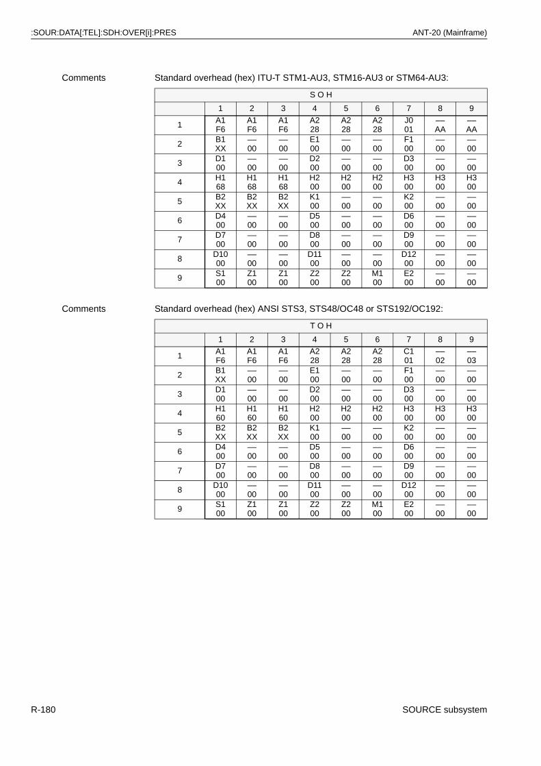
:SOUR:DATA[:TEL]:SDH:OVER[i]:PRES ANT-20 (Mainframe)
Comments Standard overhead (hex) ITU-T STM1-AU3, STM16-AU3 or STM64-AU3:
S O H
1 2 3 4 5 6 7 8 9
1 A1F6
A1F6
A1F6
A228
A228
A228
J001
––AA
––AA
2 B1XX
––00
––00
E100
––00
––00
F100
––00
––00
3 D100
––00
––00
D200
––00
––00
D300
––00
––00
4 H168
H168
H168
H200
H200
H200
H300
H300
H300
5 B2XX
B2XX
B2XX
K100
––00
––00
K200
––00
––00
6 D400
––00
––00
D500
––00
––00
D600
––00
––00
7 D700
––00
––00
D800
––00
––00
D900
––00
––00
8 D1000
––00
––00
D1100
––00
––00
D1200
––00
––00
9 S100
Z100
Z100
Z200
Z200
M100
E200
––00
––00
Comments Standard overhead (hex) ANSI STS3, STS48/OC48 or STS192/OC192:
T O H
1 2 3 4 5 6 7 8 9
1 A1F6
A1F6
A1F6
A228
A228
A228
C101
––02
––03
2 B1XX
––00
––00
E100
––00
––00
F100
––00
––00
3 D100
––00
––00
D200
––00
––00
D300
––00
––00
4 H160
H160
H160
H200
H200
H200
H300
H300
H300
5 B2XX
B2XX
B2XX
K100
––00
––00
K200
––00
––00
6 D400
––00
––00
D500
––00
––00
D600
––00
––00
7 D700
––00
––00
D800
––00
––00
D900
––00
––00
8 D1000
––00
––00
D1100
––00
––00
D1200
––00
––00
9 S100
Z100
Z100
Z200
Z200
M100
E200
––00
––00
R-180 SOURCE subsystem
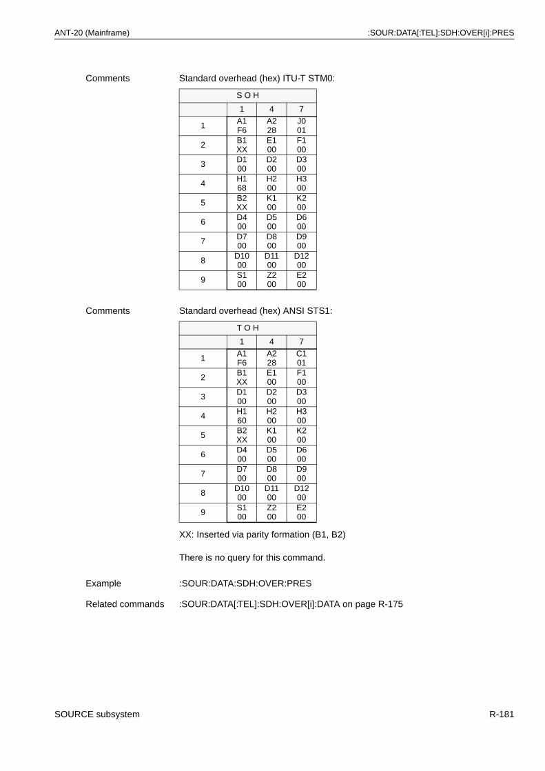
ANT-20 (Mainframe) :SOUR:DATA[:TEL]:SDH:OVER[i]:PRES
XX: Inserted via parity formation (B1, B2)
There is no query for this command.
Comments Standard overhead (hex) ITU-T STM0:
S O H
1 4 7
1 A1F6
A228
J001
2 B1XX
E100
F100
3 D100
D200
D300
4 H168
H200
H300
5 B2XX
K100
K200
6 D400
D500
D600
7 D700
D800
D900
8 D1000
D1100
D1200
9 S100
Z200
E200
Comments Standard overhead (hex) ANSI STS1:
T O H
1 4 7
1 A1F6
A228
C101
2 B1XX
E100
F100
3 D100
D200
D300
4 H160
H200
H300
5 B2XX
K100
K200
6 D400
D500
D600
7 D700
D800
D900
8 D1000
D1100
D1200
9 S100
Z200
E200
Example :SOUR:DATA:SDH:OVER:PRES
Related commands :SOUR:DATA[:TEL]:SDH:OVER[i]:DATA on page R-175
SOURCE subsystem R-181
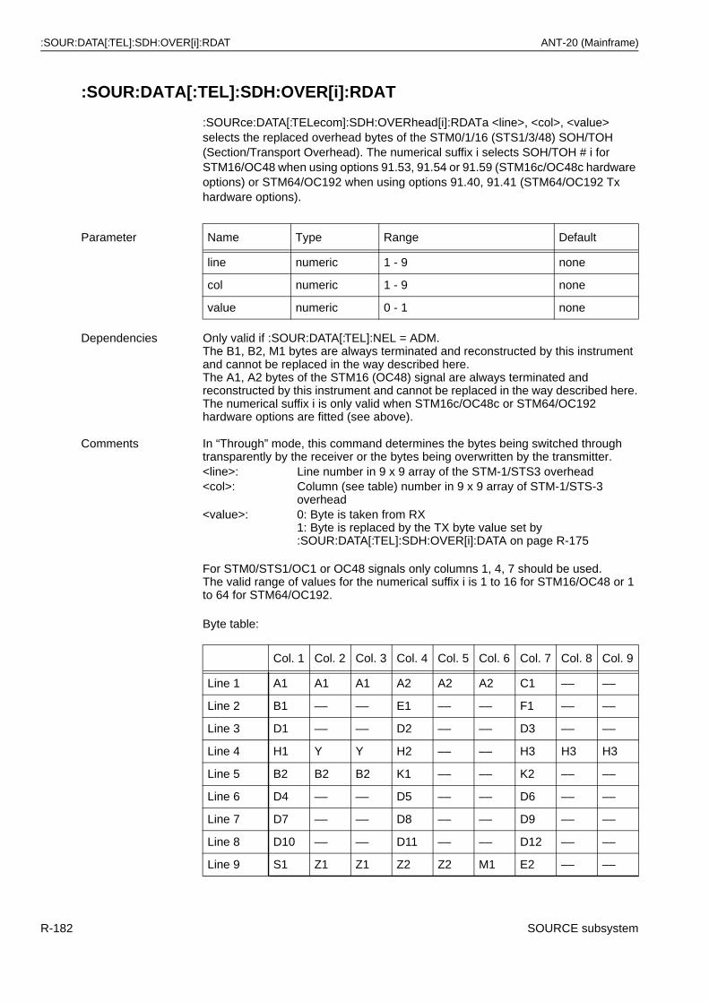
:SOUR:DATA[:TEL]:SDH:OVER[i]:RDAT ANT-20 (Mainframe)
:SOUR:DATA[:TEL]:SDH:OVER[i]:RDAT
:SOURce:DATA[:TELecom]:SDH:OVERhead[i]:RDATa <line>, <col>, <value> selects the replaced overhead bytes of the STM0/1/16 (STS1/3/48) SOH/TOH (Section/Transport Overhead). The numerical suffix i selects SOH/TOH # i for STM16/OC48 when using options 91.53, 91.54 or 91.59 (STM16c/OC48c hardware options) or STM64/OC192 when using options 91.40, 91.41 (STM64/OC192 Tx hardware options).
Byte table:
Parameter Name Type Range Default
line numeric 1 - 9 none
col numeric 1 - 9 none
value numeric 0 - 1 none
Dependencies Only valid if :SOUR:DATA[:TEL]:NEL = ADM.The B1, B2, M1 bytes are always terminated and reconstructed by this instrument and cannot be replaced in the way described here.The A1, A2 bytes of the STM16 (OC48) signal are always terminated and reconstructed by this instrument and cannot be replaced in the way described here.The numerical suffix i is only valid when STM16c/OC48c or STM64/OC192 hardware options are fitted (see above).
Comments In “Through” mode, this command determines the bytes being switched through transparently by the receiver or the bytes being overwritten by the transmitter.<line>: Line number in 9 x 9 array of the STM-1/STS3 overhead<col>: Column (see table) number in 9 x 9 array of STM-1/STS-3
overhead<value>: 0: Byte is taken from RX
1: Byte is replaced by the TX byte value set by:SOUR:DATA[:TEL]:SDH:OVER[i]:DATA on page R-175
For STM0/STS1/OC1 or OC48 signals only columns 1, 4, 7 should be used.The valid range of values for the numerical suffix i is 1 to 16 for STM16/OC48 or 1 to 64 for STM64/OC192.
Col. 1 Col. 2 Col. 3 Col. 4 Col. 5 Col. 6 Col. 7 Col. 8 Col. 9
Line 1 A1 A1 A1 A2 A2 A2 C1 –– ––
Line 2 B1 –– –– E1 –– –– F1 –– ––
Line 3 D1 –– –– D2 –– –– D3 –– ––
Line 4 H1 Y Y H2 –– –– H3 H3 H3
Line 5 B2 B2 B2 K1 –– –– K2 –– ––
Line 6 D4 –– –– D5 –– –– D6 –– ––
Line 7 D7 –– –– D8 –– –– D9 –– ––
Line 8 D10 –– –– D11 –– –– D12 –– ––
Line 9 S1 Z1 Z1 Z2 Z2 M1 E2 –– ––
R-182 SOURCE subsystem
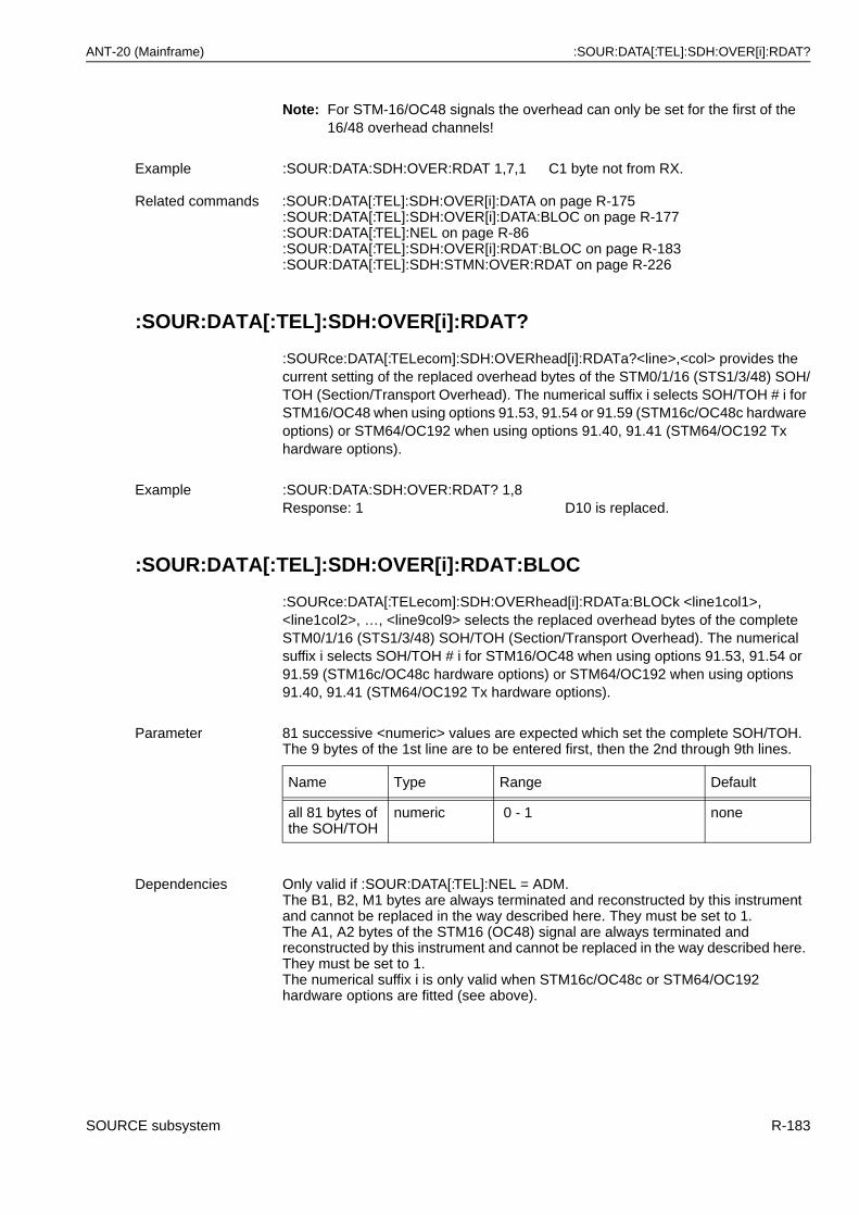
ANT-20 (Mainframe) :SOUR:DATA[:TEL]:SDH:OVER[i]:RDAT?
Note: For STM-16/OC48 signals the overhead can only be set for the first of the 16/48 overhead channels!
:SOUR:DATA[:TEL]:SDH:OVER[i]:RDAT?
:SOURce:DATA[:TELecom]:SDH:OVERhead[i]:RDATa?<line>,<col> provides the current setting of the replaced overhead bytes of the STM0/1/16 (STS1/3/48) SOH/TOH (Section/Transport Overhead). The numerical suffix i selects SOH/TOH # i for STM16/OC48 when using options 91.53, 91.54 or 91.59 (STM16c/OC48c hardware options) or STM64/OC192 when using options 91.40, 91.41 (STM64/OC192 Tx hardware options).
:SOUR:DATA[:TEL]:SDH:OVER[i]:RDAT:BLOC
:SOURce:DATA[:TELecom]:SDH:OVERhead[i]:RDATa:BLOCk <line1col1>, <line1col2>, …, <line9col9> selects the replaced overhead bytes of the complete STM0/1/16 (STS1/3/48) SOH/TOH (Section/Transport Overhead). The numerical suffix i selects SOH/TOH # i for STM16/OC48 when using options 91.53, 91.54 or 91.59 (STM16c/OC48c hardware options) or STM64/OC192 when using options 91.40, 91.41 (STM64/OC192 Tx hardware options).
Example :SOUR:DATA:SDH:OVER:RDAT 1,7,1 C1 byte not from RX.
Related commands :SOUR:DATA[:TEL]:SDH:OVER[i]:DATA on page R-175:SOUR:DATA[:TEL]:SDH:OVER[i]:DATA:BLOC on page R-177:SOUR:DATA[:TEL]:NEL on page R-86:SOUR:DATA[:TEL]:SDH:OVER[i]:RDAT:BLOC on page R-183:SOUR:DATA[:TEL]:SDH:STMN:OVER:RDAT on page R-226
Example :SOUR:DATA:SDH:OVER:RDAT? 1,8Response: 1 D10 is replaced.
Parameter 81 successive <numeric> values are expected which set the complete SOH/TOH. The 9 bytes of the 1st line are to be entered first, then the 2nd through 9th lines.
Name Type Range Default
all 81 bytes of the SOH/TOH
numeric 0 - 1 none
Dependencies Only valid if :SOUR:DATA[:TEL]:NEL = ADM.The B1, B2, M1 bytes are always terminated and reconstructed by this instrument and cannot be replaced in the way described here. They must be set to 1.The A1, A2 bytes of the STM16 (OC48) signal are always terminated and reconstructed by this instrument and cannot be replaced in the way described here. They must be set to 1.The numerical suffix i is only valid when STM16c/OC48c or STM64/OC192 hardware options are fitted (see above).
SOURCE subsystem R-183
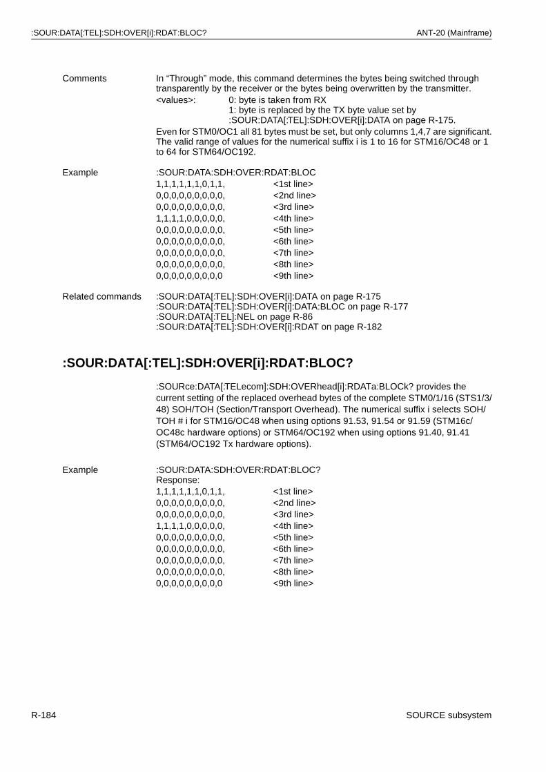
:SOUR:DATA[:TEL]:SDH:OVER[i]:RDAT:BLOC? ANT-20 (Mainframe)
:SOUR:DATA[:TEL]:SDH:OVER[i]:RDAT:BLOC?
:SOURce:DATA[:TELecom]:SDH:OVERhead[i]:RDATa:BLOCk? provides the current setting of the replaced overhead bytes of the complete STM0/1/16 (STS1/3/48) SOH/TOH (Section/Transport Overhead). The numerical suffix i selects SOH/TOH # i for STM16/OC48 when using options 91.53, 91.54 or 91.59 (STM16c/OC48c hardware options) or STM64/OC192 when using options 91.40, 91.41 (STM64/OC192 Tx hardware options).
Comments In “Through” mode, this command determines the bytes being switched through transparently by the receiver or the bytes being overwritten by the transmitter.<values>: 0: byte is taken from RX
1: byte is replaced by the TX byte value set by :SOUR:DATA[:TEL]:SDH:OVER[i]:DATA on page R-175.
Even for STM0/OC1 all 81 bytes must be set, but only columns 1,4,7 are significant.The valid range of values for the numerical suffix i is 1 to 16 for STM16/OC48 or 1 to 64 for STM64/OC192.
Example :SOUR:DATA:SDH:OVER:RDAT:BLOC1,1,1,1,1,1,0,1,1, <1st line>0,0,0,0,0,0,0,0,0, <2nd line>0,0,0,0,0,0,0,0,0, <3rd line>1,1,1,1,0,0,0,0,0, <4th line>0,0,0,0,0,0,0,0,0, <5th line>0,0,0,0,0,0,0,0,0, <6th line>0,0,0,0,0,0,0,0,0, <7th line>0,0,0,0,0,0,0,0,0, <8th line>0,0,0,0,0,0,0,0,0 <9th line>
Related commands :SOUR:DATA[:TEL]:SDH:OVER[i]:DATA on page R-175:SOUR:DATA[:TEL]:SDH:OVER[i]:DATA:BLOC on page R-177:SOUR:DATA[:TEL]:NEL on page R-86:SOUR:DATA[:TEL]:SDH:OVER[i]:RDAT on page R-182
Example :SOUR:DATA:SDH:OVER:RDAT:BLOC?Response:1,1,1,1,1,1,0,1,1, <1st line>0,0,0,0,0,0,0,0,0, <2nd line>0,0,0,0,0,0,0,0,0, <3rd line>1,1,1,1,0,0,0,0,0, <4th line>0,0,0,0,0,0,0,0,0, <5th line>0,0,0,0,0,0,0,0,0, <6th line>0,0,0,0,0,0,0,0,0, <7th line>0,0,0,0,0,0,0,0,0, <8th line>0,0,0,0,0,0,0,0,0 <9th line>
R-184 SOURCE subsystem
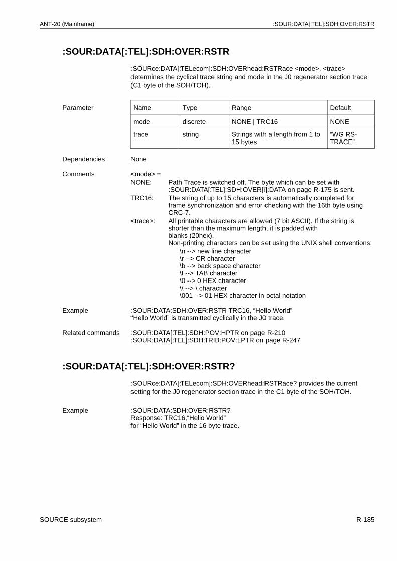
ANT-20 (Mainframe) :SOUR:DATA[:TEL]:SDH:OVER:RSTR
:SOUR:DATA[:TEL]:SDH:OVER:RSTR
:SOURce:DATA[:TELecom]:SDH:OVERhead:RSTRace <mode>, <trace> determines the cyclical trace string and mode in the J0 regenerator section trace (C1 byte of the SOH/TOH).
:SOUR:DATA[:TEL]:SDH:OVER:RSTR?
:SOURce:DATA[:TELecom]:SDH:OVERhead:RSTRace? provides the current setting for the J0 regenerator section trace in the C1 byte of the SOH/TOH.
Parameter Name Type Range Default
mode discrete NONE | TRC16 NONE
trace string Strings with a length from 1 to 15 bytes
“WG RS-TRACE”
Dependencies None
Comments <mode> =NONE: Path Trace is switched off. The byte which can be set with
:SOUR:DATA[:TEL]:SDH:OVER[i]:DATA on page R-175 is sent.TRC16: The string of up to 15 characters is automatically completed for
frame synchronization and error checking with the 16th byte using CRC-7.
<trace>: All printable characters are allowed (7 bit ASCII). If the string isshorter than the maximum length, it is padded withblanks (20hex).Non-printing characters can be set using the UNIX shell conventions:
\n --> new line character\r --> CR character\b --> back space character\t --> TAB character\0 --> 0 HEX character\\ --> \ character\001 --> 01 HEX character in octal notation
Example :SOUR:DATA:SDH:OVER:RSTR TRC16, “Hello World”“Hello World” is transmitted cyclically in the J0 trace.
Related commands :SOUR:DATA[:TEL]:SDH:POV:HPTR on page R-210:SOUR:DATA[:TEL]:SDH:TRIB:POV:LPTR on page R-247
Example :SOUR:DATA:SDH:OVER:RSTR?Response: TRC16,“Hello World”for “Hello World” in the 16 byte trace.
SOURCE subsystem R-185
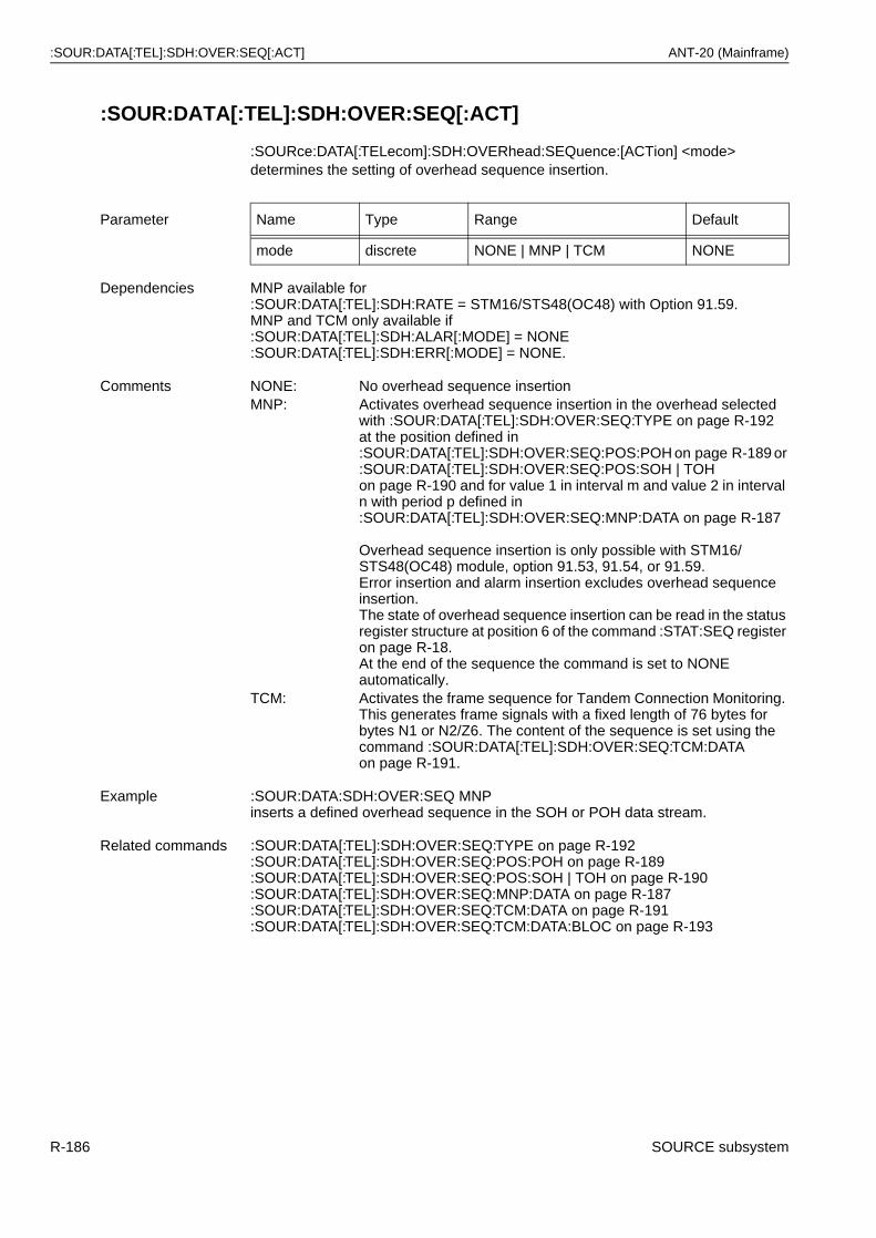
:SOUR:DATA[:TEL]:SDH:OVER:SEQ[:ACT] ANT-20 (Mainframe)
:SOUR:DATA[:TEL]:SDH:OVER:SEQ[:ACT]
:SOURce:DATA[:TELecom]:SDH:OVERhead:SEQuence:[ACTion] <mode> determines the setting of overhead sequence insertion.
Parameter Name Type Range Default
mode discrete NONE | MNP | TCM NONE
Dependencies MNP available for:SOUR:DATA[:TEL]:SDH:RATE = STM16/STS48(OC48) with Option 91.59.MNP and TCM only available if:SOUR:DATA[:TEL]:SDH:ALAR[:MODE] = NONE:SOUR:DATA[:TEL]:SDH:ERR[:MODE] = NONE.
Comments NONE: No overhead sequence insertionMNP: Activates overhead sequence insertion in the overhead selected
with :SOUR:DATA[:TEL]:SDH:OVER:SEQ:TYPE on page R-192at the position defined in :SOUR:DATA[:TEL]:SDH:OVER:SEQ:POS:POH on page R-189 or :SOUR:DATA[:TEL]:SDH:OVER:SEQ:POS:SOH | TOH on page R-190 and for value 1 in interval m and value 2 in interval n with period p defined in :SOUR:DATA[:TEL]:SDH:OVER:SEQ:MNP:DATA on page R-187
Overhead sequence insertion is only possible with STM16/STS48(OC48) module, option 91.53, 91.54, or 91.59.Error insertion and alarm insertion excludes overhead sequence insertion.The state of overhead sequence insertion can be read in the status register structure at position 6 of the command :STAT:SEQ register on page R-18.At the end of the sequence the command is set to NONE automatically.
TCM: Activates the frame sequence for Tandem Connection Monitoring. This generates frame signals with a fixed length of 76 bytes for bytes N1 or N2/Z6. The content of the sequence is set using the command :SOUR:DATA[:TEL]:SDH:OVER:SEQ:TCM:DATA on page R-191.
Example :SOUR:DATA:SDH:OVER:SEQ MNPinserts a defined overhead sequence in the SOH or POH data stream.
Related commands :SOUR:DATA[:TEL]:SDH:OVER:SEQ:TYPE on page R-192:SOUR:DATA[:TEL]:SDH:OVER:SEQ:POS:POH on page R-189:SOUR:DATA[:TEL]:SDH:OVER:SEQ:POS:SOH | TOH on page R-190:SOUR:DATA[:TEL]:SDH:OVER:SEQ:MNP:DATA on page R-187:SOUR:DATA[:TEL]:SDH:OVER:SEQ:TCM:DATA on page R-191:SOUR:DATA[:TEL]:SDH:OVER:SEQ:TCM:DATA:BLOC on page R-193
R-186 SOURCE subsystem
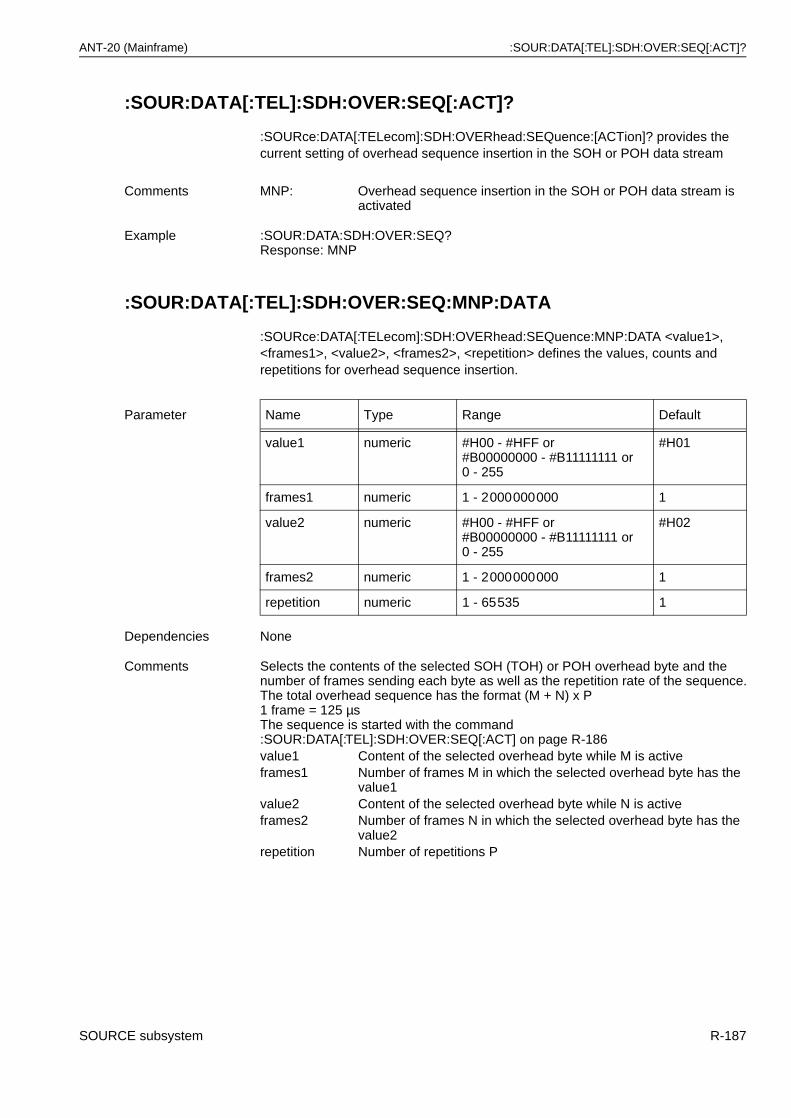
ANT-20 (Mainframe) :SOUR:DATA[:TEL]:SDH:OVER:SEQ[:ACT]?
:SOUR:DATA[:TEL]:SDH:OVER:SEQ[:ACT]?
:SOURce:DATA[:TELecom]:SDH:OVERhead:SEQuence:[ACTion]? provides the current setting of overhead sequence insertion in the SOH or POH data stream
:SOUR:DATA[:TEL]:SDH:OVER:SEQ:MNP:DATA
:SOURce:DATA[:TELecom]:SDH:OVERhead:SEQuence:MNP:DATA <value1>, <frames1>, <value2>, <frames2>, <repetition> defines the values, counts and repetitions for overhead sequence insertion.
Comments MNP: Overhead sequence insertion in the SOH or POH data stream is activated
Example :SOUR:DATA:SDH:OVER:SEQ?Response: MNP
Parameter Name Type Range Default
value1 numeric #H00 - #HFF or#B00000000 - #B11111111 or 0 - 255
#H01
frames1 numeric 1 - 2000000000 1
value2 numeric #H00 - #HFF or#B00000000 - #B11111111 or 0 - 255
#H02
frames2 numeric 1 - 2000000000 1
repetition numeric 1 - 65535 1
Dependencies None
Comments Selects the contents of the selected SOH (TOH) or POH overhead byte and the number of frames sending each byte as well as the repetition rate of the sequence.The total overhead sequence has the format (M + N) x P1 frame = 125 µsThe sequence is started with the command :SOUR:DATA[:TEL]:SDH:OVER:SEQ[:ACT] on page R-186value1 Content of the selected overhead byte while M is activeframes1 Number of frames M in which the selected overhead byte has the
value1value2 Content of the selected overhead byte while N is activeframes2 Number of frames N in which the selected overhead byte has the
value2repetition Number of repetitions P
SOURCE subsystem R-187
:SOUR:DATA[:TEL]:SDH:OVER:SEQ:MNP:DATA? ANT-20 (Mainframe)
:SOUR:DATA[:TEL]:SDH:OVER:SEQ:MNP:DATA?
:SOURce:DATA[:TELecom]:SDH:OVERhead:SEQuence:MNP:DATA? provides the current settings of the overhead sequence insertion counts, values and repetitions in the SOH (TOH) or POH data stream:
Example :SOUR:DATA:SDH:OVER:SEQ:MNP:DATA 0, 8000, #HC2, 32000, 100specifies the following sequence: The selected SOH (TOH) or POH overhead byte is present with the value 0 for 8000 frames, followed by 32000 frames with the value C2 Hex (194), followed by 8000 frames with the value 0 and 32000 frames with the value C2 Hex and so on for 100 cycles. Then the overhead byte returns to its original value.
Related commands :SOUR:DATA[:TEL]:SDH:OVER:SEQ[:ACT] on page R-186:SOUR:DATA[:TEL]:SDH:OVER:SEQ:TYPE on page R-192:SOUR:DATA[:TEL]:SDH:OVER:SEQ:POS:POH on page R-189:SOUR:DATA[:TEL]:SDH:OVER:SEQ:POS:SOH | TOH on page R-190
Example :SOUR:DATA:SDH:OVER:SEQ:MNP:DATA?Response: 12, 8000, 24, 32000,100 The selected overhead byte is
inserted with the value 12 for 8000 frames, followed by 32000 frames with the value 24. This sequence is repeated 100 times.
R-188 SOURCE subsystem
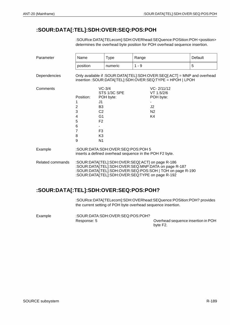
ANT-20 (Mainframe) :SOUR:DATA[:TEL]:SDH:OVER:SEQ:POS:POH
:SOUR:DATA[:TEL]:SDH:OVER:SEQ:POS:POH
:SOURce:DATA[:TELecom]:SDH:OVERhead:SEQuence:POSition:POH <position> determines the overhead byte position for POH overhead sequence insertion.
:SOUR:DATA[:TEL]:SDH:OVER:SEQ:POS:POH?
:SOURce:DATA[:TELecom]:SDH:OVERhead:SEQuence:POSition:POH? provides the current setting of POH byte overhead sequence insertion.
Parameter Name Type Range Default
position numeric 1 - 9 5
Dependencies Only available if :SOUR:DATA[:TEL]:SDH:OVER:SEQ[:ACT] = MNP and overhead insertion :SOUR:DATA[:TEL]:SDH:OVER:SEQ:TYPE = HPOH | LPOH
Comments
Position:
VC-3/4STS 1/3C SPEPOH byte:
VC- 2/11/12VT 1.5/2/6POH byte:
1 J1 -2 B3 J23 C2 N24 G1 K45 F26 -7 F38 K39 N1
Example :SOUR:DATA:SDH:OVER:SEQ:POS:POH 5inserts a defined overhead sequence in the POH F2 byte.
Related commands :SOUR:DATA[:TEL]:SDH:OVER:SEQ[:ACT] on page R-186:SOUR:DATA[:TEL]:SDH:OVER:SEQ:MNP:DATA on page R-187:SOUR:DATA[:TEL]:SDH:OVER:SEQ:POS:SOH | TOH on page R-190:SOUR:DATA[:TEL]:SDH:OVER:SEQ:TYPE on page R-192
Example :SOUR:DATA:SDH:OVER:SEQ:POS:POH?Response: 5 Overhead sequence insertion in POH
byte F2.
SOURCE subsystem R-189
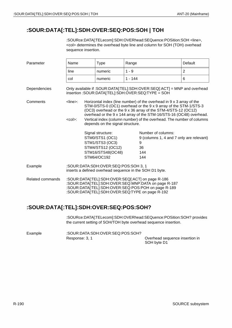
:SOUR:DATA[:TEL]:SDH:OVER:SEQ:POS:SOH | TOH ANT-20 (Mainframe)
:SOUR:DATA[:TEL]:SDH:OVER:SEQ:POS:SOH | TOH
:SOURce:DATA[:TELecom]:SDH:OVERhead:SEQuence:POSition:SOH <line>, <col> determines the overhead byte line and column for SOH (TOH) overhead sequence insertion.
:SOUR:DATA[:TEL]:SDH:OVER:SEQ:POS:SOH?
:SOURce:DATA[:TELecom]:SDH:OVERhead:SEQuence:POSition:SOH? provides the current setting of SOH/TOH byte overhead sequence insertion.
Parameter Name Type Range Default
line numeric 1 - 9 2
col numeric 1 - 144 6
Dependencies Only available if :SOUR:DATA[:TEL]:SDH:OVER:SEQ[:ACT] = MNP and overhead insertion :SOUR:DATA[:TEL]:SDH:OVER:SEQ:TYPE = SOH
Comments <line>: Horizontal index (line number) of the overhead in 9 x 3 array of the STM-0/STS-0 (OC1) overhead or the 9 x 9 array of the STM-1/STS-3 (OC3) overhead or the 9 x 36 array of the STM-4/STS-12 (OC12) overhead or the 9 x 144 array of the STM-16/STS-16 (OC48) overhead.
<col>: Vertical index (column number) of the overhead. The number of columns depends on the signal structure.
Signal structure: Number of columns:STM0/STS1 (OC1) 9 (columns 1, 4 and 7 only are relevant)STM1/STS3 (OC3) 9STM4/STS12 (OC12) 36STM16/STS48(OC48) 144STM64/OC192 144
Example :SOUR:DATA:SDH:OVER:SEQ:POS:SOH 3, 1inserts a defined overhead sequence in the SOH D1 byte.
Related commands :SOUR:DATA[:TEL]:SDH:OVER:SEQ[:ACT] on page R-186:SOUR:DATA[:TEL]:SDH:OVER:SEQ:MNP:DATA on page R-187:SOUR:DATA[:TEL]:SDH:OVER:SEQ:POS:POH on page R-189:SOUR:DATA[:TEL]:SDH:OVER:SEQ:TYPE on page R-192
Example :SOUR:DATA:SDH:OVER:SEQ:POS:SOH?Response: 3, 1 Overhead sequence insertion in
SOH byte D1
R-190 SOURCE subsystem

ANT-20 (Mainframe) :SOUR:DATA[:TEL]:SDH:OVER:SEQ:TCM:DATA
:SOUR:DATA[:TEL]:SDH:OVER:SEQ:TCM:DATA
:SOURce:DATA[:TELecom]:SDH:OVERhead:SEQuence:TCMonitoring:DATA <position>, <value> sets the byte in the frame sequence for Tandem Connection Monitoring at the specified position to the specified value.
:SOUR:DATA[:TEL]:SDH:OVER:SEQ:TCM:DATA?
:SOURce:DATA[:TELecom]:SDH:OVERhead:SEQuence:TCMonitoring:DATA?,<position> provides the current settings of individual overhead bytes in the frame sequence.
Parameter Name Type Range Default
position numeric 1 - 76 none
value numeric #H00 - #HFF or#B00000000 - #B11111111 or 0 - 255
none
Dependencies None
Comments This command allows individual setting of the bytes in the frame sequence for Tandem Connection Monitoring.<position>: Position in the 76 byte array of the frame sequence.<value>: Value of the byte designated by <position>.
Example :SOUR:DATA:SDH:OVER:SEQ:TCM:DATA,73,#H01sets byte 73 in frame sequence to 01hex (RDI).
Related commands :SOUR:DATA[:TEL]:SDH:OVER:SEQ:TCM:DATA:BLOC on page R-193
Example :SOUR:DATA:SDH:OVER:SEQ:TCM:DATA? 8Response: 128 byte # 8 is actually set to 80hex.
SOURCE subsystem R-191
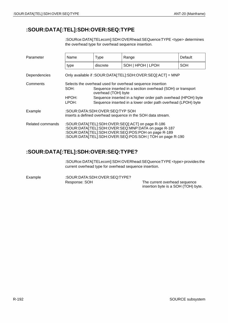
:SOUR:DATA[:TEL]:SDH:OVER:SEQ:TYPE ANT-20 (Mainframe)
:SOUR:DATA[:TEL]:SDH:OVER:SEQ:TYPE
:SOURce:DATA[:TELecom]:SDH:OVERhead:SEQuence:TYPE <type> determines the overhead type for overhead sequence insertion.
:SOUR:DATA[:TEL]:SDH:OVER:SEQ:TYPE?
:SOURce:DATA[:TELecom]:SDH:OVERhead:SEQuence:TYPE <type> provides the current overhead type for overhead sequence insertion.
Parameter Name Type Range Default
type discrete SOH | HPOH | LPOH SOH
Dependencies Only available if :SOUR:DATA[:TEL]:SDH:OVER:SEQ[:ACT] = MNP
Comments Selects the overhead used for overhead sequence insertionSOH: Sequence inserted in a section overhead (SOH) or transport
overhead (TOH) byteHPOH: Sequence inserted in a higher order path overhead (HPOH) byteLPOH: Sequence inserted in a lower order path overhead (LPOH) byte
Example :SOUR:DATA:SDH:OVER:SEQ:TYP SOHinserts a defined overhead sequence in the SOH data stream.
Related commands :SOUR:DATA[:TEL]:SDH:OVER:SEQ[:ACT] on page R-186:SOUR:DATA[:TEL]:SDH:OVER:SEQ:MNP:DATA on page R-187:SOUR:DATA[:TEL]:SDH:OVER:SEQ:POS:POH on page R-189:SOUR:DATA[:TEL]:SDH:OVER:SEQ:POS:SOH | TOH on page R-190
Example :SOUR:DATA:SDH:OVER:SEQ:TYPE?Response: SOH The current overhead sequence
insertion byte is a SOH (TOH) byte.
R-192 SOURCE subsystem
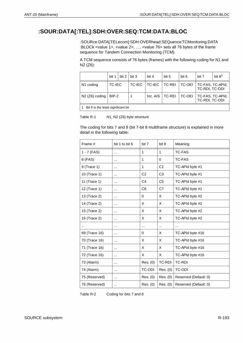
ANT-20 (Mainframe) :SOUR:DATA[:TEL]:SDH:OVER:SEQ:TCM:DATA:BLOC
:SOUR:DATA[:TEL]:SDH:OVER:SEQ:TCM:DATA:BLOC
:SOURce:DATA[:TELecom]:SDH:OVERhead:SEQuence:TCMonitoring:DATA:BLOCk <value 1>, <value 2>, …, <value 76> sets all 76 bytes of the frame sequence for Tandem Connection Monitoring (TCM).
A TCM sequence consists of 76 bytes (frames) with the following coding for N1 and N2 (Z6):
The coding for bits 7 and 8 (bit 7-bit 8 multiframe structure) is explained in more detail in the following table:
bit 1 bit 2 bit 3 bit 4 bit 5 bit 6 bit 7 bit 81
N1 coding TC-IEC TC-IEC TC-IEC TC-REI TC-OEI TC-FAS, TC-APId,TC-RDI, TC-ODI
N2 (Z6) coding BIP-2 1 Inc. AIS TC-REI TC-OEI TC-FAS, TC-APId,TC-RDI, TC-ODI
1 Bit 8 is the least significant bit
Table R-1 N1, N2 (Z6) byte structure
Frame # bit 1 to bit 6 bit 7 bit 8 Meaning
1 - 7 (FAS) ... 1 1 TC-FAS
8 (FAS) ... 1 0 TC-FAS
9 (Trace 1) ... 1 C1 TC-APId byte #1
10 (Trace 1) ... C2 C3 TC-APId byte #1
11 (Trace 1) ... C4 C5 TC-APId byte #1
12 (Trace 1) ... C6 C7 TC-APId byte #1
13 (Trace 2) ... 0 X TC-APId byte #2
14 (Trace 2) ... X X TC-APId byte #2
15 (Trace 2) ... X X TC-APId byte #2
16 (Trace 2) ... X X TC-APId byte #2
... ... ... ... ...
69 (Trace 16) ... 0 X TC-APId byte #16
70 (Trace 16) ... X X TC-APId byte #16
71 (Trace 16) ... X X TC-APId byte #16
72 (Trace 16) ... X X TC-APId byte #16
73 (Alarm) ... Res. (0) TC-RDI TC-RDI
74 (Alarm) ... TC-ODI Res. (0) TC-ODI
75 (Reserved) ... Res. (0) Res. (0) Reserved (Default: 0)
76 (Reserved) ... Res. (0) Res. (0) Reserved (Default: 0)
Table R-2 Coding for bits 7 and 8
SOURCE subsystem R-193
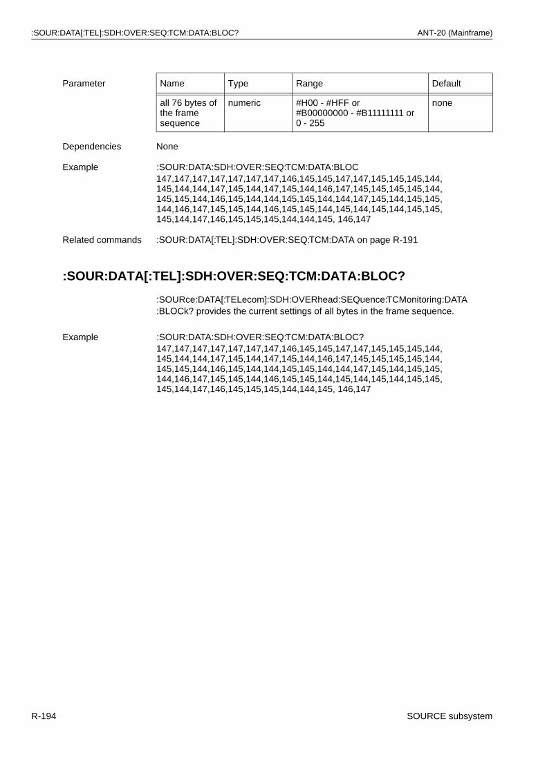
:SOUR:DATA[:TEL]:SDH:OVER:SEQ:TCM:DATA:BLOC? ANT-20 (Mainframe)
:SOUR:DATA[:TEL]:SDH:OVER:SEQ:TCM:DATA:BLOC?
:SOURce:DATA[:TELecom]:SDH:OVERhead:SEQuence:TCMonitoring:DATA:BLOCk? provides the current settings of all bytes in the frame sequence.
Parameter Name Type Range Default
all 76 bytes of the frame sequence
numeric #H00 - #HFF or#B00000000 - #B11111111 or 0 - 255
none
Dependencies None
Example :SOUR:DATA:SDH:OVER:SEQ:TCM:DATA:BLOC147,147,147,147,147,147,147,146,145,145,147,147,145,145,145,144,145,144,144,147,145,144,147,145,144,146,147,145,145,145,145,144,145,145,144,146,145,144,144,145,145,144,144,147,145,144,145,145,144,146,147,145,145,144,146,145,145,144,145,144,145,144,145,145,145,144,147,146,145,145,145,144,144,145, 146,147
Related commands :SOUR:DATA[:TEL]:SDH:OVER:SEQ:TCM:DATA on page R-191
Example :SOUR:DATA:SDH:OVER:SEQ:TCM:DATA:BLOC?147,147,147,147,147,147,147,146,145,145,147,147,145,145,145,144,145,144,144,147,145,144,147,145,144,146,147,145,145,145,145,144,145,145,144,146,145,144,144,145,145,144,144,147,145,144,145,145,144,146,147,145,145,144,146,145,145,144,145,144,145,144,145,145,145,144,147,146,145,145,145,144,144,145, 146,147
R-194 SOURCE subsystem
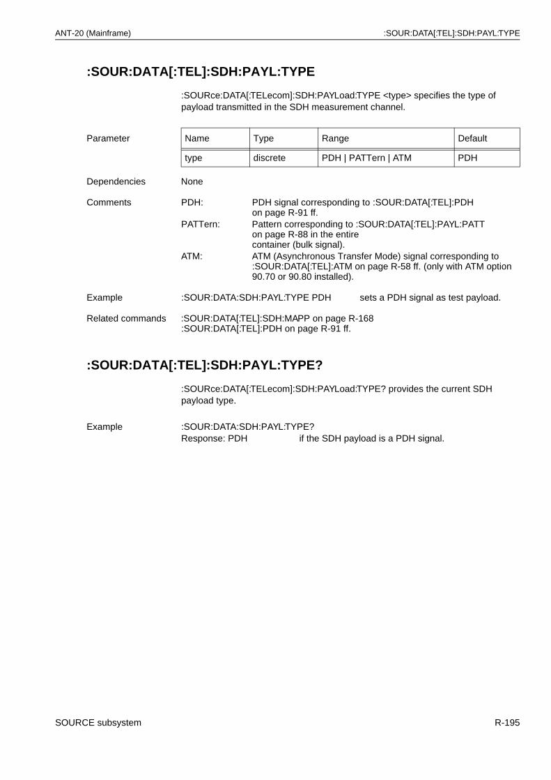
ANT-20 (Mainframe) :SOUR:DATA[:TEL]:SDH:PAYL:TYPE
:SOUR:DATA[:TEL]:SDH:PAYL:TYPE
:SOURce:DATA[:TELecom]:SDH:PAYLoad:TYPE <type> specifies the type of payload transmitted in the SDH measurement channel.
:SOUR:DATA[:TEL]:SDH:PAYL:TYPE?
:SOURce:DATA[:TELecom]:SDH:PAYLoad:TYPE? provides the current SDH payload type.
Parameter Name Type Range Default
type discrete PDH | PATTern | ATM PDH
Dependencies None
Comments PDH: PDH signal corresponding to :SOUR:DATA[:TEL]:PDH on page R-91 ff.
PATTern: Pattern corresponding to :SOUR:DATA[:TEL]:PAYL:PATT on page R-88 in the entirecontainer (bulk signal).
ATM: ATM (Asynchronous Transfer Mode) signal corresponding to:SOUR:DATA[:TEL]:ATM on page R-58 ff. (only with ATM option 90.70 or 90.80 installed).
Example :SOUR:DATA:SDH:PAYL:TYPE PDH sets a PDH signal as test payload.
Related commands :SOUR:DATA[:TEL]:SDH:MAPP on page R-168:SOUR:DATA[:TEL]:PDH on page R-91 ff.
Example :SOUR:DATA:SDH:PAYL:TYPE?Response: PDH if the SDH payload is a PDH signal.
SOURCE subsystem R-195
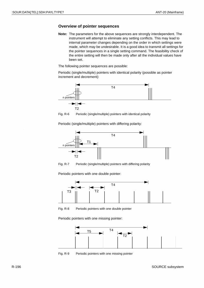
:SOUR:DATA[:TEL]:SDH:PAYL:TYPE? ANT-20 (Mainframe)
Overview of pointer sequences
Note: The parameters for the above sequences are strongly interdependent. The instrument will attempt to eliminate any setting conflicts. This may lead to internal parameter changes depending on the order in which settings were made, which may be undesirable. It is a good idea to transmit all settings for the pointer sequences in a single setting command. The feasibility check of the entire setting will then be made only after all the individual values have been set.
The following pointer sequences are possible:
Periodic (single/multiple) pointers with identical polarity (possible as pointer increment and decrement):
Fig. R-6 Periodic (single/multiple) pointers with identical polarity
Periodic (single/multiple) pointers with differing polarity::
Fig. R-7 Periodic (single/multiple) pointers with differing polarity
Periodic pointers with one double pointer:
Fig. R-8 Periodic pointers with one double pointer
Periodic pointers with one missing pointer:
Fig. R-9 Periodic pointers with one missing pointer
T4
n pointers
T2
T4
T2
n pointersT1
T2
T4
T3
T4
T2T5
R-196 SOURCE subsystem
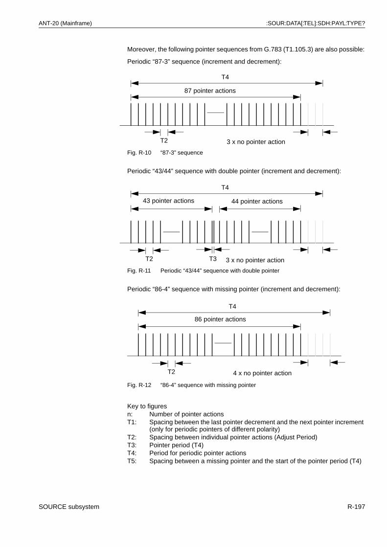
ANT-20 (Mainframe) :SOUR:DATA[:TEL]:SDH:PAYL:TYPE?
Moreover, the following pointer sequences from G.783 (T1.105.3) are also possible:
Periodic “87-3” sequence (increment and decrement):
Fig. R-10 “87-3” sequence
Periodic “43/44” sequence with double pointer (increment and decrement):
Fig. R-11 Periodic “43/44” sequence with double pointer
Periodic “86-4” sequence with missing pointer (increment and decrement):
Fig. R-12 “86-4” sequence with missing pointer
Key to figuresn: Number of pointer actionsT1: Spacing between the last pointer decrement and the next pointer increment
(only for periodic pointers of different polarity)T2: Spacing between individual pointer actions (Adjust Period)T3: Pointer period (T4)T4: Period for periodic pointer actionsT5: Spacing between a missing pointer and the start of the pointer period (T4)
87 pointer actions
3 x no pointer actionT2
T4
43 pointer actions
3 x no pointer actionT3
44 pointer actions
T2
T4
86 pointer actions
4 x no pointer actionT2
T4
SOURCE subsystem R-197
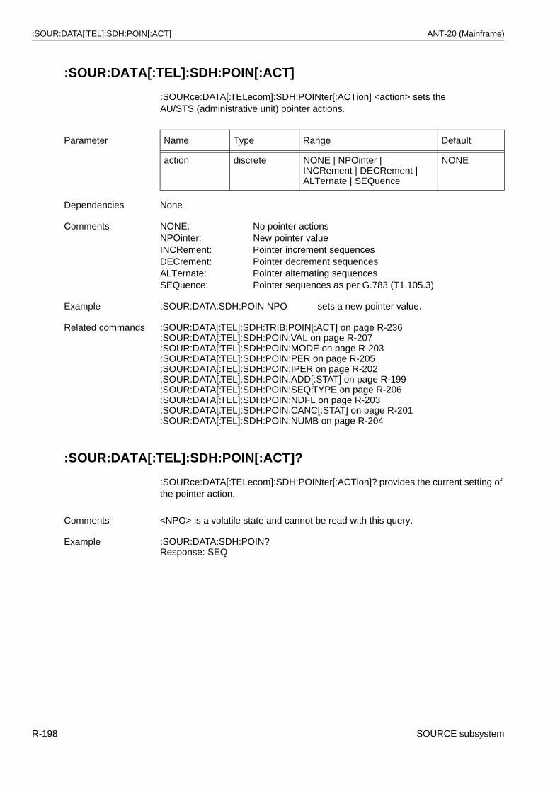
:SOUR:DATA[:TEL]:SDH:POIN[:ACT] ANT-20 (Mainframe)
:SOUR:DATA[:TEL]:SDH:POIN[:ACT]
:SOURce:DATA[:TELecom]:SDH:POINter[:ACTion] <action> sets theAU/STS (administrative unit) pointer actions.
:SOUR:DATA[:TEL]:SDH:POIN[:ACT]?
:SOURce:DATA[:TELecom]:SDH:POINter[:ACTion]? provides the current setting of the pointer action.
Parameter Name Type Range Default
action discrete NONE | NPOinter |INCRement | DECRement | ALTernate | SEQuence
NONE
Dependencies None
Comments NONE: No pointer actionsNPOinter: New pointer valueINCRement: Pointer increment sequencesDECrement: Pointer decrement sequencesALTernate: Pointer alternating sequencesSEQuence: Pointer sequences as per G.783 (T1.105.3)
Example :SOUR:DATA:SDH:POIN NPO sets a new pointer value.
Related commands :SOUR:DATA[:TEL]:SDH:TRIB:POIN[:ACT] on page R-236:SOUR:DATA[:TEL]:SDH:POIN:VAL on page R-207:SOUR:DATA[:TEL]:SDH:POIN:MODE on page R-203:SOUR:DATA[:TEL]:SDH:POIN:PER on page R-205:SOUR:DATA[:TEL]:SDH:POIN:IPER on page R-202:SOUR:DATA[:TEL]:SDH:POIN:ADD[:STAT] on page R-199:SOUR:DATA[:TEL]:SDH:POIN:SEQ:TYPE on page R-206:SOUR:DATA[:TEL]:SDH:POIN:NDFL on page R-203:SOUR:DATA[:TEL]:SDH:POIN:CANC[:STAT] on page R-201:SOUR:DATA[:TEL]:SDH:POIN:NUMB on page R-204
Comments <NPO> is a volatile state and cannot be read with this query.
Example :SOUR:DATA:SDH:POIN?Response: SEQ
R-198 SOURCE subsystem
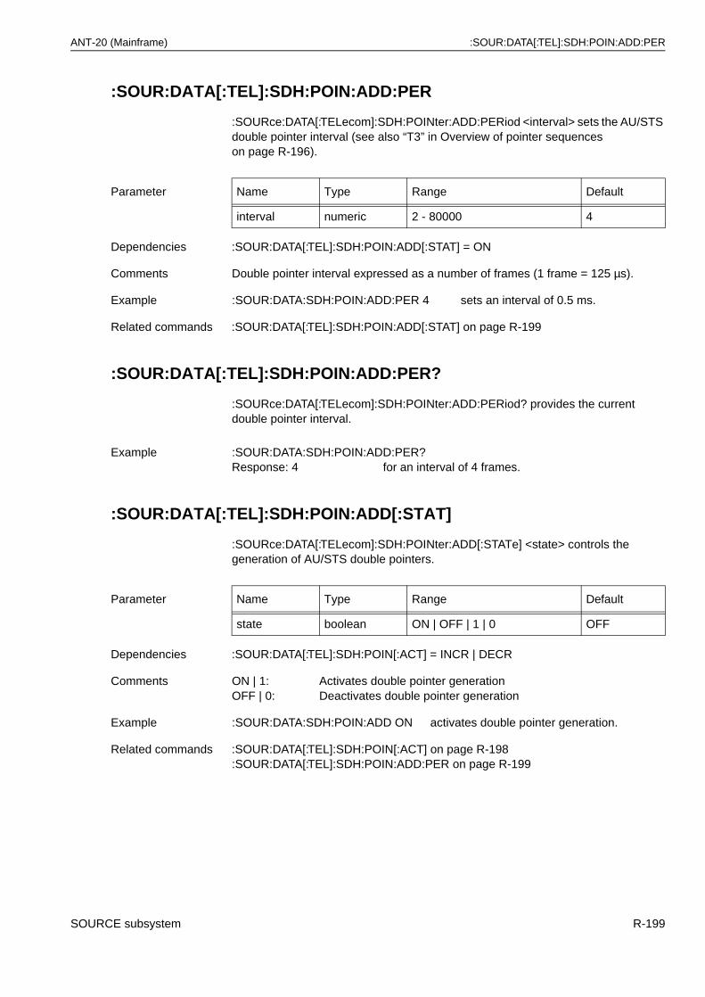
ANT-20 (Mainframe) :SOUR:DATA[:TEL]:SDH:POIN:ADD:PER
:SOUR:DATA[:TEL]:SDH:POIN:ADD:PER
:SOURce:DATA[:TELecom]:SDH:POINter:ADD:PERiod <interval> sets the AU/STS double pointer interval (see also “T3” in Overview of pointer sequences on page R-196).
:SOUR:DATA[:TEL]:SDH:POIN:ADD:PER?
:SOURce:DATA[:TELecom]:SDH:POINter:ADD:PERiod? provides the current double pointer interval.
:SOUR:DATA[:TEL]:SDH:POIN:ADD[:STAT]
:SOURce:DATA[:TELecom]:SDH:POINter:ADD[:STATe] <state> controls the generation of AU/STS double pointers.
Parameter Name Type Range Default
interval numeric 2 - 80000 4
Dependencies :SOUR:DATA[:TEL]:SDH:POIN:ADD[:STAT] = ON
Comments Double pointer interval expressed as a number of frames (1 frame = 125 µs).
Example :SOUR:DATA:SDH:POIN:ADD:PER 4 sets an interval of 0.5 ms.
Related commands :SOUR:DATA[:TEL]:SDH:POIN:ADD[:STAT] on page R-199
Example :SOUR:DATA:SDH:POIN:ADD:PER?Response: 4 for an interval of 4 frames.
Parameter Name Type Range Default
state boolean ON | OFF | 1 | 0 OFF
Dependencies :SOUR:DATA[:TEL]:SDH:POIN[:ACT] = INCR | DECR
Comments ON | 1: Activates double pointer generationOFF | 0: Deactivates double pointer generation
Example :SOUR:DATA:SDH:POIN:ADD ON activates double pointer generation.
Related commands :SOUR:DATA[:TEL]:SDH:POIN[:ACT] on page R-198:SOUR:DATA[:TEL]:SDH:POIN:ADD:PER on page R-199
SOURCE subsystem R-199
:SOUR:DATA[:TEL]:SDH:POIN:ADD[:STAT]? ANT-20 (Mainframe)
:SOUR:DATA[:TEL]:SDH:POIN:ADD[:STAT]?
:SOURce:DATA[:TELecom]:SDH:POINter:ADD[:STATe]? provides the current setting of AU/STS double pointer generation.
:SOUR:DATA[:TEL]:SDH:POIN:APER
:SOURce:DATA[:TELecom]:SDH:POINter:APERiod <period> sets the adjust period (see also “T2” in Overview of pointer sequences on page R-196).
:SOUR:DATA[:TEL]:SDH:POIN:APER?
:SOURce:DATA[:TELecom]:SDH:POINter:APERiod? provides the adjust period.
Example :SOUR:DATA:SDH:POIN:ADD?Response: 0 if double pointer generation is switched off.
Parameter Name Type Range Default
period numeric 2 - 80000 4
Parameter None
Comments <frames>: Pointer adjust period expressed as a number of frames(1 frame = 125 µs).
Example :SOUR:DATA:SDH:POIN:APER 10000 sets the adjust period to 10000 frames.
Related commands :SOUR:DATA[:TEL]:SDH:POIN[:ACT] on page R-198:SOUR:DATA[:TEL]:SDH:POIN:IPER on page R-202:SOUR:DATA[:TEL]:SDH:POIN:PER on page R-205
Example :SOUR:DATA:SDH:POIN:APER?Response: 10000
R-200 SOURCE subsystem
ANT-20 (Mainframe) :SOUR:DATA[:TEL]:SDH:POIN:CANC:PER
:SOUR:DATA[:TEL]:SDH:POIN:CANC:PER
:SOURce:DATA[:TELecom]:SDH:POINter:CANCel:PERiod <interval> sets the interval for cancellation of AU/STS pointer actions (see also “T5” in Overview of pointer sequences on page R-196).
:SOUR:DATA[:TEL]:SDH:POIN:CANC:PER?
:SOURce:DATA[:TELecom]:SDH:POINter:CANCel:PERiod? provides the interval for cancellation of pointer actions.
:SOUR:DATA[:TEL]:SDH:POIN:CANC[:STAT]
:SOURce:DATA[:TELecom]:SDH:POINter:CANCel[:STATe] <state> controls the cancellation of AU/STS pointer actions.
Parameter Name Type Range Default
interval numeric 0 - 4800000 16000
Dependencies :SOUR:DATA[:TEL]:SDH:POIN:CANC[:STAT] = ON
Comments Interval for cancellation of pointer actions expressed as a number of frames(1 frame = 125 µs).
Example :SOUR:DATA:SDH:POIN:CANC:PER 4 sets an interval of 0.5 ms.
Related commands :SOUR:DATA[:TEL]:SDH:POIN:CANC[:STAT] on page R-201
Example :SOUR:DATA:SDH:POIN:CANC:PER?Response: 4 for an interval of 4 frames.
Parameter Name Type Range Default
state boolean ON | OFF | 1 | 0 OFF
Dependencies :SOUR:DATA[:TEL]:SDH:POIN[:ACT] = INCR | DECR
Comments ON | 1: Activates cancellation of pointer actionsOFF | 0: Deactivates cancellation of pointer actions
Example :SOUR:DATA:SDH:POIN:CANC ON activates cancellation of pointer actions.
Related commands :SOUR:DATA[:TEL]:SDH:POIN[:ACT] on page R-198:SOUR:DATA[:TEL]:SDH:POIN:CANC:PER on page R-201
SOURCE subsystem R-201
:SOUR:DATA[:TEL]:SDH:POIN:CANC[:STAT]? ANT-20 (Mainframe)
:SOUR:DATA[:TEL]:SDH:POIN:CANC[:STAT]?
:SOURce:DATA[:TELecom]:SDH:POINter:CANCel[:STATe]? provides the current setting of the cancellation of AU/STS pointer actions.
:SOUR:DATA[:TEL]:SDH:POIN:IPER
:SOURce:DATA[:TELecom]:SDH:POINter:IPERiod <period> sets the inversion period (see also “T1” in Overview of pointer sequences on page R-196).
:SOUR:DATA[:TEL]:SDH:POIN:IPER?
:SOURce:DATA[:TELecom]:SDH:POINter:IPERiod? provides the inversion period.
Example :SOUR:DATA:SDH:POIN:CANC?Response: 0 if cancellation of pointer actions is switched off.
Parameter Name Type Range Default
period numeric 2 - 4800000 8000
Dependencies :SOUR:DATA[:TEL]:SDH:POIN[:ACT] = ALT
Comments <frames>: AU/STS pointer inversion period expressed as a number of frames(1 frame = 125 µs).
Example :SOUR:DATA:SDH:POIN:IPER 10000sets the inversion period to 10000 frames.
Related commands :SOUR:DATA[:TEL]:SDH:POIN[:ACT] on page R-198:SOUR:DATA[:TEL]:SDH:POIN:ADD[:STAT] on page R-199:SOUR:DATA[:TEL]:SDH:POIN:PER on page R-205
Example :SOUR:DATA:SDH:POIN:IPER?Response: 10000
R-202 SOURCE subsystem
ANT-20 (Mainframe) :SOUR:DATA[:TEL]:SDH:POIN:MODE
:SOUR:DATA[:TEL]:SDH:POIN:MODE
:SOURce:DATA[:TELecom]:SDH:POINter:MODE <mode> sets the execution mode of the pointer sequence.
:SOUR:DATA[:TEL]:SDH:POIN:MODE?
:SOURce:DATA[:TELecom]:SDH:POINter:MODE? provides the execution mode for the pointer sequence.
:SOUR:DATA[:TEL]:SDH:POIN:NDFL
:SOURce:DATA[:TELecom]:SDH:POINter:NDFLag <state> controls NDF generation when a new AU/STS pointer is set.
Parameter Name Type Range Default
mode discrete SINGle | PERiodical PER
Dependencies None
Comments SINGle: Single execution of sequencePERiodical: Periodic execution of sequence
Example :SOUR:DATA:SDH:POIN:MODE SING sets a single run.
Related commands :SOUR:DATA[:TEL]:SDH:POIN[:ACT] on page R-198:SOUR:DATA[:TEL]:SDH:POIN:SEQ:TYPE on page R-206
Comments SING is a volatile state and cannot be read.
Example :SOUR:DATA:SDH:POIN:MODE?Response: PER
Parameter Name Type Range Default
state boolean ON | OFF | 1 | 0 ON
Dependencies :SOUR:DATA[:TEL]:SDH:POIN[:ACT] = NPO
Comments ON | 1: Activates NDF (New Data Flag) generationOFF | 0: Deactivates NDF generation
Example :SOUR:DATA:SDH:POIN:NDFL ON when a pointer appears, NDF is set.
Related commands :SOUR:DATA[:TEL]:SDH:POIN[:ACT] on page R-198
SOURCE subsystem R-203
:SOUR:DATA[:TEL]:SDH:POIN:NDFL? ANT-20 (Mainframe)
:SOUR:DATA[:TEL]:SDH:POIN:NDFL?
:SOURce:DATA[:TELecom]:SDH:POINter:NDFLag? provides the NDF initial value when setting new pointers.
:SOUR:DATA[:TEL]:SDH:POIN:NUMB
:SOURce:DATA[:TELecom]:SDH:POINter:NUMBer <number> sets the number of multiple pointers (see also “n” in Overview of pointer sequences on page R-196).
:SOUR:DATA[:TEL]:SDH:POIN:NUMB?
:SOURce:DATA[:TELecom]:SDH:POINter:NUMBer? provides the number of multiple pointers.
Example :SOUR:DATA:SDH:POIN:NDFL?Response: 1 if NDF is set.
Parameter Name Type Range Default
number numeric 1 - 2000 1
Dependencies :SOUR:DATA[:TEL]:SDH:POIN[:ACT] = INCR | DECR | ALT.
Example :SOUR:DATA:SDH:POIN:NUMB 3 sets pointer actions.
Related commands :SOUR:DATA[:TEL]:SDH:POIN[:ACT] on page R-198:SOUR:DATA[:TEL]:SDH:POIN:IPER on page R-202:SOUR:DATA[:TEL]:SDH:POIN:ADD[:STAT] on page R-199:SOUR:DATA[:TEL]:SDH:POIN:PER on page R-205
Example :SOUR:DATA:SDH:POIN:NUMB?Response: 1
R-204 SOURCE subsystem
ANT-20 (Mainframe) :SOUR:DATA[:TEL]:SDH:POIN:PER
:SOUR:DATA[:TEL]:SDH:POIN:PER
:SOURce:DATA[:TELecom]:SDH:POINter:PERiod <period> sets the AU/STS pointer period (see also “T4” in Overview of pointer sequences on page R-196).
:SOUR:DATA[:TEL]:SDH:POIN:PER?
:SOURce:DATA[:TELecom]:SDH:POINter:PER? provides the pointer period.
:SOUR:DATA[:TEL]:SDH:POIN:SEQ:DIR
:SOURce:DATA[:TELecom]:SDH:POINter:SEQuence:DIRection <direction> sets the direction of AU/STS pointer sequences as per G.783 (T1.105.3).
Parameter Name Type Range Default
period numeric 2 - 4800000 16000
Dependencies None
Comments <period>: Pointer period expressed as a number of frames (1 frame = 125 µs).
Example :SOUR:DATA:SDH:POIN:PER 1000 sets the pointer period to 1000 frames.
Related commands :SOUR:DATA[:TEL]:SDH:POIN[:ACT] on page R-198:SOUR:DATA[:TEL]:SDH:POIN:IPER on page R-202:SOUR:DATA[:TEL]:SDH:POIN:ADD[:STAT] on page R-199
Example :SOUR:DATA:SDH:POIN:PER?Response: 1000
Parameter Name Type Range Default
direction discrete UP | DOWN UP
Dependencies :SOUR:DATA[:TEL]:SDH:POIN[:ACT] = SEQ
Comments UP: Executes sequence with pointer incrementsDOWN: Executes sequence with pointer decrements
Example :SOUR:DATA:SDH:POIN:SEQ:DIR UPsets sequences with increasing pointers.
Related commands :SOUR:DATA[:TEL]:SDH:POIN:SEQ:TYPE on page R-206
SOURCE subsystem R-205
:SOUR:DATA[:TEL]:SDH:POIN:SEQ:DIR? ANT-20 (Mainframe)
:SOUR:DATA[:TEL]:SDH:POIN:SEQ:DIR?
:SOURce:DATA[:TELecom]:SDH:POINter:SEQuence:DIRection? provides the direction of pointer sequences as per G.783 (T1.105.3).
:SOUR:DATA[:TEL]:SDH:POIN:SEQ:TYPE
:SOURce:DATA[:TELecom]:SDH:POINter:SEQuence:TYPE <type> sets the AU/STS pointer sequences as per G.783 (T1.105.3).
:SOUR:DATA[:TEL]:SDH:POIN:SEQ:TYPE?
:SOURce:DATA[:TELecom]:SDH:POINter:SEQuence:TYPE? provides the sequence setting as per G.783 (T1.105.3).
Example :SOUR:DATA:SDH:POIN:SEQ:DIR?Response: DOWN
Parameter Name Type Range Default
type discrete S873 | S4344 | S864 S873
Dependencies :SOUR:DATA[:TEL]:SDH:POIN[:ACT] = SEQ
Comments S873: Sequence: 87-3 patternS4344: Sequence: 43-44 pattern with double pointerS864: Sequence: 86-4 pattern with missing pointer
Example :SOUR:DATA:SDH:POIN:SEQ:TYPE S873 sets the 87-3 pattern.
Related commands :SOUR:DATA[:TEL]:SDH:POIN[:ACT] on page R-198:SOUR:DATA[:TEL]:SDH:POIN:SEQ:DIR on page R-205
Example :SOUR:DATA:SDH:POIN:SEQ:TYPE?Response: S873
R-206 SOURCE subsystem
ANT-20 (Mainframe) :SOUR:DATA[:TEL]:SDH:POIN:SSB
:SOUR:DATA[:TEL]:SDH:POIN:SSB
:SOURce:DATA[:TELecom]:SDH:POINter:SSBits <value> sets the value of the SS bits in the H1 byte.
:SOUR:DATA[:TEL]:SDH:POIN:SSB?
:SOURce:DATA[:TELecom]:SDH:POINter:SSBits? provides the value of the SS bits.
:SOUR:DATA[:TEL]:SDH:POIN:VAL
:SOURce:DATA[:TELecom]:SDH:POINter:VALue <value> sets the value of the AU/STS pointer activated by :SOUR:DATA[:TEL]:SDH:POIN[:ACT] = NPO.
:SOUR:DATA[:TEL]:SDH:POIN:VAL?
:SOURce:DATA[:TELecom]:SDH:POINter:VALue? provides the pointer value.
Parameter Name Type Range Default
value numeric 0 - 3 2
Dependencies None
Comments When the system is switched between ITU-T and ANSI, the value is reset as follows:If :SOUR:DATA[:TEL]:STAN = ITUT reset to 2,if :SOUR:DATA[:TEL]:STAN = ANSI reset to 0.
Example :SOUR:DATA:SDH:POIN:SSB 0; sets the SS bits to binary 00.
Example :SOUR:DATA:SDH:POIN:SSB?Response: 0
Parameter Name Type Range Default
value numeric 0 - 782 0
Dependencies :SOUR:DATA[:TEL]:SDH:POIN[:ACT] = NPO must be transmitted to activate the new pointer value set by this command.
Comments AU-4, AU-3: 0-782
Example :SOUR:DATA:SDH:POIN:VAL 10;:SOUR:DATA:SDH:POIN NPO sets the pointer value to 10.
Related commands :SOUR:DATA[:TEL]:SDH:POIN[:ACT] on page R-198
Example :SOUR:DATA:SDH:POIN:VAL?Response: 10
SOURCE subsystem R-207
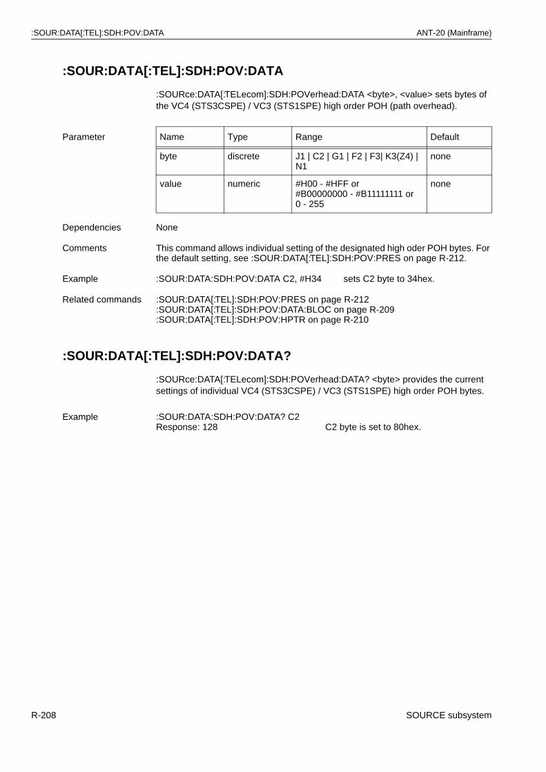
:SOUR:DATA[:TEL]:SDH:POV:DATA ANT-20 (Mainframe)
:SOUR:DATA[:TEL]:SDH:POV:DATA
:SOURce:DATA[:TELecom]:SDH:POVerhead:DATA <byte>, <value> sets bytes of the VC4 (STS3CSPE) / VC3 (STS1SPE) high order POH (path overhead).
:SOUR:DATA[:TEL]:SDH:POV:DATA?
:SOURce:DATA[:TELecom]:SDH:POVerhead:DATA? <byte> provides the current settings of individual VC4 (STS3CSPE) / VC3 (STS1SPE) high order POH bytes.
Parameter Name Type Range Default
byte discrete J1 | C2 | G1 | F2 | F3| K3(Z4) | N1
none
value numeric #H00 - #HFF or#B00000000 - #B11111111 or 0 - 255
none
Dependencies None
Comments This command allows individual setting of the designated high oder POH bytes. For the default setting, see :SOUR:DATA[:TEL]:SDH:POV:PRES on page R-212.
Example :SOUR:DATA:SDH:POV:DATA C2, #H34 sets C2 byte to 34hex.
Related commands :SOUR:DATA[:TEL]:SDH:POV:PRES on page R-212:SOUR:DATA[:TEL]:SDH:POV:DATA:BLOC on page R-209:SOUR:DATA[:TEL]:SDH:POV:HPTR on page R-210
Example :SOUR:DATA:SDH:POV:DATA? C2Response: 128 C2 byte is set to 80hex.
R-208 SOURCE subsystem
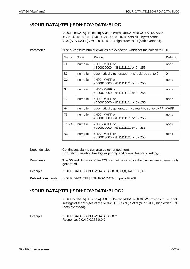
ANT-20 (Mainframe) :SOUR:DATA[:TEL]:SDH:POV:DATA:BLOC
:SOUR:DATA[:TEL]:SDH:POV:DATA:BLOC
:SOURce:DATA[:TELecom]:SDH:POVerhead:DATA:BLOCk <J1>, <B3>,<C2>, <G1>, <F2>, <H4>, <F3>, <K3>, <N1> sets all 9 bytes of theVC4 (STS3CSPE) / VC3 (STS1SPE) high order POH (path overhead).
:SOUR:DATA[:TEL]:SDH:POV:DATA:BLOC?
:SOURce:DATA[:TELecom]:SDH:POVerhead:DATA:BLOCk? provides the current settings of the 9 bytes of the VC4 (STS3CSPE) / VC3 (STS1SPE) high order POH (path overhead).
Parameter Nine successive numeric values are expected, which set the complete POH.
Name Type Range Default
J1 numeric #H00 - #HFF or#B00000000 - #B11111111 or 0 - 255
none
B3 numeric automatically generated --> should be set to 0 0
C2 numeric #H00 - #HFF or#B00000000 - #B11111111 or 0 - 255
none
G1 numeric #H00 - #HFF or#B00000000 - #B11111111 or 0 - 255
none
F2 numeric #H00 - #HFF or#B00000000 - #B11111111 or 0 - 255
none
H4 numeric automatically generated --> should be set to #HFF #HFF
F3 numeric #H00 - #HFF or#B00000000 - #B11111111 or 0 - 255
none
K3(Z4) numeric #H00 - #HFF or#B00000000 - #B11111111 or 0 - 255
none
N1 numeric #H00 - #HFF or#B00000000 - #B11111111 or 0 - 255
none
Dependencies Continuous alarms can also be generated here. Error/alarm insertion has higher priority and overwrites static settings!
Comments The B3 and H4 bytes of the POH cannot be set since their values are automatically generated.
Example :SOUR:DATA:SDH:POV:DATA:BLOC 0,0,4,0,0,#HFF,0,0,0
Related commands :SOUR:DATA[:TEL]:SDH:POV:DATA on page R-208
Example :SOUR:DATA:SDH:POV:DATA:BLOC?Response: 0,0,4,0,0,255,0,0,0
SOURCE subsystem R-209
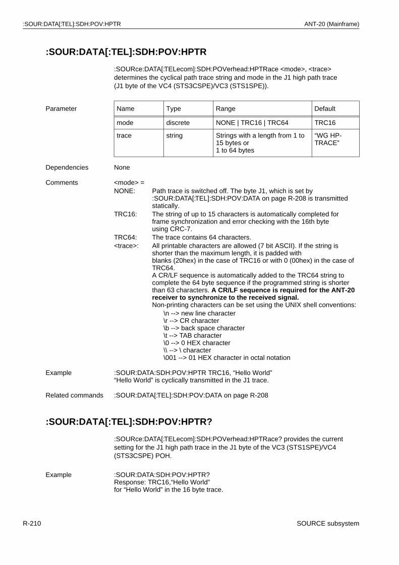
:SOUR:DATA[:TEL]:SDH:POV:HPTR ANT-20 (Mainframe)
:SOUR:DATA[:TEL]:SDH:POV:HPTR
:SOURce:DATA[:TELecom]:SDH:POVerhead:HPTRace <mode>, <trace> determines the cyclical path trace string and mode in the J1 high path trace(J1 byte of the VC4 (STS3CSPE)/VC3 (STS1SPE)).
:SOUR:DATA[:TEL]:SDH:POV:HPTR?
:SOURce:DATA[:TELecom]:SDH:POVerhead:HPTRace? provides the current setting for the J1 high path trace in the J1 byte of the VC3 (STS1SPE)/VC4 (STS3CSPE) POH.
Parameter Name Type Range Default
mode discrete NONE | TRC16 | TRC64 TRC16
trace string Strings with a length from 1 to 15 bytes or 1 to 64 bytes
“WG HP-TRACE”
Dependencies None
Comments <mode> =NONE: Path trace is switched off. The byte J1, which is set by
:SOUR:DATA[:TEL]:SDH:POV:DATA on page R-208 is transmitted statically.
TRC16: The string of up to 15 characters is automatically completed forframe synchronization and error checking with the 16th byteusing CRC-7.
TRC64: The trace contains 64 characters.<trace>: All printable characters are allowed (7 bit ASCII). If the string is
shorter than the maximum length, it is padded withblanks (20hex) in the case of TRC16 or with 0 (00hex) in the case of TRC64.A CR/LF sequence is automatically added to the TRC64 string to complete the 64 byte sequence if the programmed string is shorter than 63 characters. A CR/LF sequence is required for the ANT-20 receiver to synchronize to the received signal.Non-printing characters can be set using the UNIX shell conventions:
\n --> new line character\r --> CR character\b --> back space character\t --> TAB character\0 --> 0 HEX character\\ --> \ character\001 --> 01 HEX character in octal notation
Example :SOUR:DATA:SDH:POV:HPTR TRC16, “Hello World”“Hello World” is cyclically transmitted in the J1 trace.
Related commands :SOUR:DATA[:TEL]:SDH:POV:DATA on page R-208
Example :SOUR:DATA:SDH:POV:HPTR?Response: TRC16,“Hello World”for “Hello World” in the 16 byte trace.
R-210 SOURCE subsystem
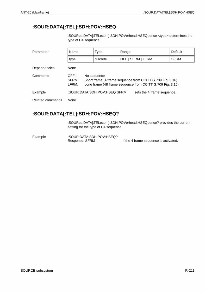
ANT-20 (Mainframe) :SOUR:DATA[:TEL]:SDH:POV:HSEQ
:SOUR:DATA[:TEL]:SDH:POV:HSEQ
:SOURce:DATA[:TELecom]:SDH:POVerhead:HSEQuence <type> determines the type of H4 sequence.
:SOUR:DATA[:TEL]:SDH:POV:HSEQ?
:SOURce:DATA[:TELecom]:SDH:POVerhead:HSEQuence? provides the current setting for the type of H4 sequence.
Parameter Name Type Range Default
type discrete OFF | SFRM | LFRM SFRM
Dependencies None
Comments OFF: No sequenceSFRM: Short frame (4 frame sequence from CCITT G.709 Fig. 3.16)LFRM: Long frame (48 frame sequence from CCITT G.709 Fig. 3.15)
Example :SOUR:DATA:SDH:POV:HSEQ SFRM sets the 4 frame sequence.
Related commands None
Example :SOUR:DATA:SDH:POV:HSEQ?Response: SFRM if the 4 frame sequence is activated.
SOURCE subsystem R-211
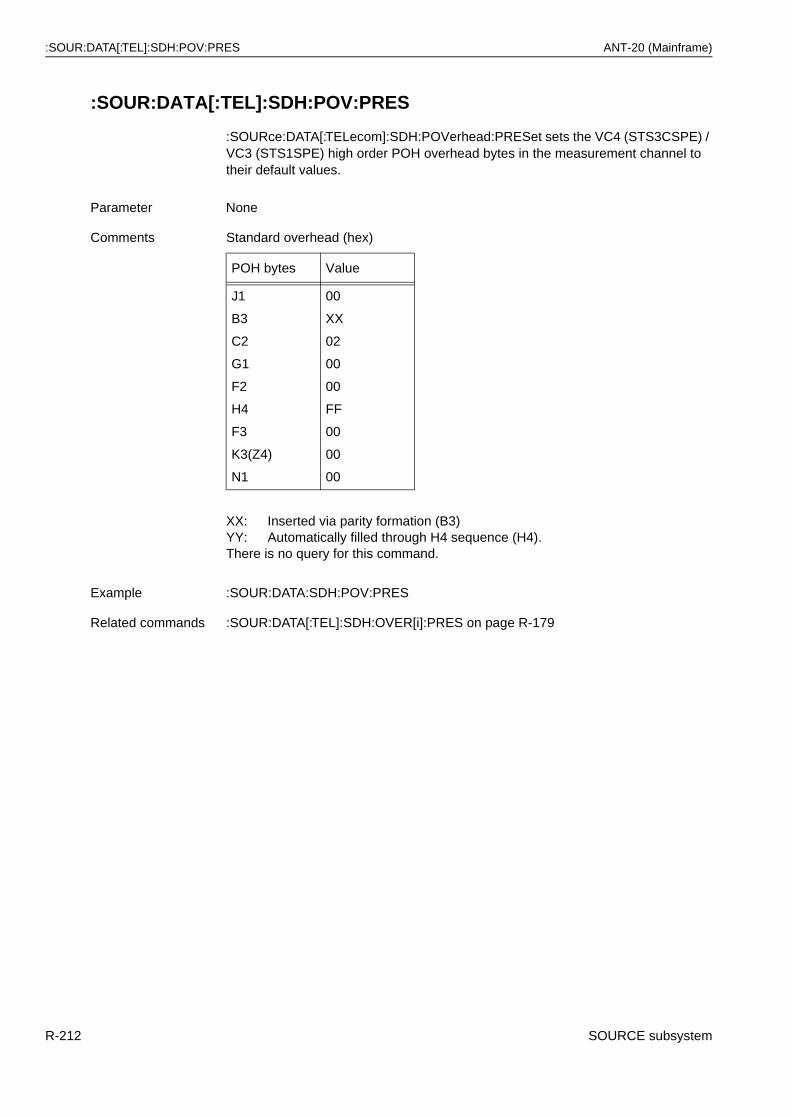
:SOUR:DATA[:TEL]:SDH:POV:PRES ANT-20 (Mainframe)
:SOUR:DATA[:TEL]:SDH:POV:PRES
:SOURce:DATA[:TELecom]:SDH:POVerhead:PRESet sets the VC4 (STS3CSPE) / VC3 (STS1SPE) high order POH overhead bytes in the measurement channel to their default values.
Parameter None
Comments Standard overhead (hex)
POH bytes Value
J1
B3
C2
G1
F2
H4
F3
K3(Z4)
N1
00
XX
02
00
00
FF
00
00
00
XX: Inserted via parity formation (B3)YY: Automatically filled through H4 sequence (H4).There is no query for this command.
Example :SOUR:DATA:SDH:POV:PRES
Related commands :SOUR:DATA[:TEL]:SDH:OVER[i]:PRES on page R-179
R-212 SOURCE subsystem
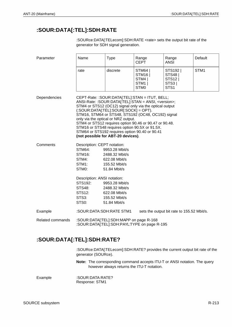
ANT-20 (Mainframe) :SOUR:DATA[:TEL]:SDH:RATE
:SOUR:DATA[:TEL]:SDH:RATE
:SOURce:DATA[:TELecom]:SDH:RATE <rate> sets the output bit rate of the generator for SDH signal generation.
:SOUR:DATA[:TEL]:SDH:RATE?
:SOURce:DATA[:TELecom]:SDH:RATE? provides the current output bit rate of the generator (SOURce).
Note: The corresponding command accepts ITU-T or ANSI notation. The query however always returns the ITU-T notation.
Parameter Name Type Range CEPT
RangeANSI
Default
rate discrete STM64 | STM16 |STM4 |STM1 |STM0
STS192 | STS48 |STS12 |STS3 |STS1
STM1
Dependencies CEPT-Rate: :SOUR:DATA[:TEL]:STAN = ITUT, BELL;ANSI-Rate: :SOUR:DATA[:TEL]:STAN = ANSI, <version>;STM4 or STS12 (OC12) signal only via the optical output (:SOUR:DATA[:TEL]:SOUR[:SOCK] = OPT).STM16, STM64 or STS48, STS192 (OC48, OC192) signalonly via the optical or NRZ output.STM4 or STS12 requires option 90.46 or 90.47 or 90.48.STM16 or STS48 requires option 90.5X or 91.5X.STM64 or STS192 requires option 90.40 or 90.41(not possible for ABT-20 devices).
Comments Description: CEPT notation:STM64: 9953.28 Mbit/sSTM16: 2488.32 Mbit/sSTM4: 622.08 Mbit/sSTM1: 155.52 Mbit/sSTM0: 51.84 Mbit/s
Description: ANSI notation:STS192: 9953.28 Mbit/sSTS48: 2488.32 Mbit/sSTS12: 622.08 Mbit/sSTS3: 155.52 Mbit/sSTS0: 51.84 Mbit/s
Example :SOUR:DATA:SDH:RATE STM1 sets the output bit rate to 155.52 Mbit/s.
Related commands :SOUR:DATA[:TEL]:SDH:MAPP on page R-168:SOUR:DATA[:TEL]:SDH:PAYL:TYPE on page R-195
Example :SOUR:DATA:RATE?Response: STM1
SOURCE subsystem R-213
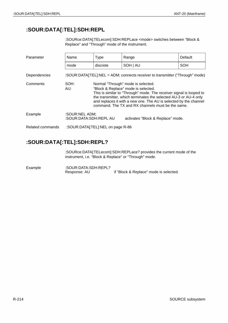
:SOUR:DATA[:TEL]:SDH:REPL ANT-20 (Mainframe)
:SOUR:DATA[:TEL]:SDH:REPL
:SOURce:DATA[:TELecom]:SDH:REPLace <mode> switches between “Block & Replace” and “Through” mode of the instrument.
:SOUR:DATA[:TEL]:SDH:REPL?
:SOURce:DATA[:TELecom]:SDH:REPLace? provides the current mode of the instrument, i.e. “Block & Replace” or “Through” mode.
Parameter Name Type Range Default
mode discrete SOH | AU SOH
Dependencies :SOUR:DATA[:TEL]:NEL = ADM; connects receiver to transmitter (“Through” mode)
Comments SOH: Normal “Through” mode is selected.AU: “Block & Replace” mode is selected.
This is similar to “Through” mode. The receiver signal is looped to the transmitter, which terminates the selected AU-3 or AU-4 only and replaces it with a new one. The AU is selected by the channel command. The TX and RX channels must be the same.
Example :SOUR:NEL ADM; :SOUR:DATA:SDH:REPL AU activates “Block & Replace” mode.
Related commands :SOUR:DATA[:TEL]:NEL on page R-86
Example :SOUR:DATA:SDH:REPL?Response: AU if “Block & Replace” mode is selected.
R-214 SOURCE subsystem
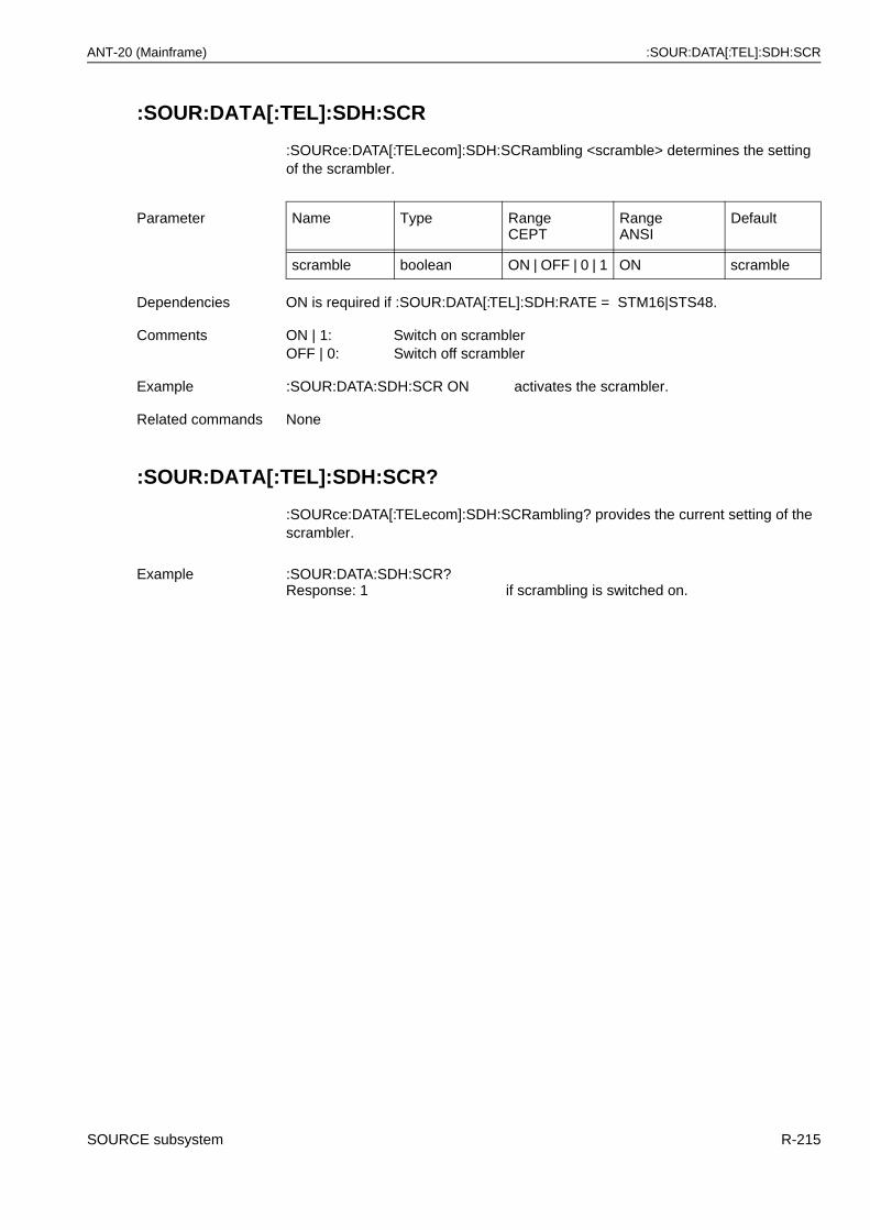
ANT-20 (Mainframe) :SOUR:DATA[:TEL]:SDH:SCR
:SOUR:DATA[:TEL]:SDH:SCR
:SOURce:DATA[:TELecom]:SDH:SCRambling <scramble> determines the setting of the scrambler.
:SOUR:DATA[:TEL]:SDH:SCR?
:SOURce:DATA[:TELecom]:SDH:SCRambling? provides the current setting of the scrambler.
Parameter Name Type Range CEPT
RangeANSI
Default
scramble boolean ON | OFF | 0 | 1 ON scramble
Dependencies ON is required if :SOUR:DATA[:TEL]:SDH:RATE = STM16|STS48.
Comments ON | 1: Switch on scramblerOFF | 0: Switch off scrambler
Example :SOUR:DATA:SDH:SCR ON activates the scrambler.
Related commands None
Example :SOUR:DATA:SDH:SCR?Response: 1 if scrambling is switched on.
SOURCE subsystem R-215
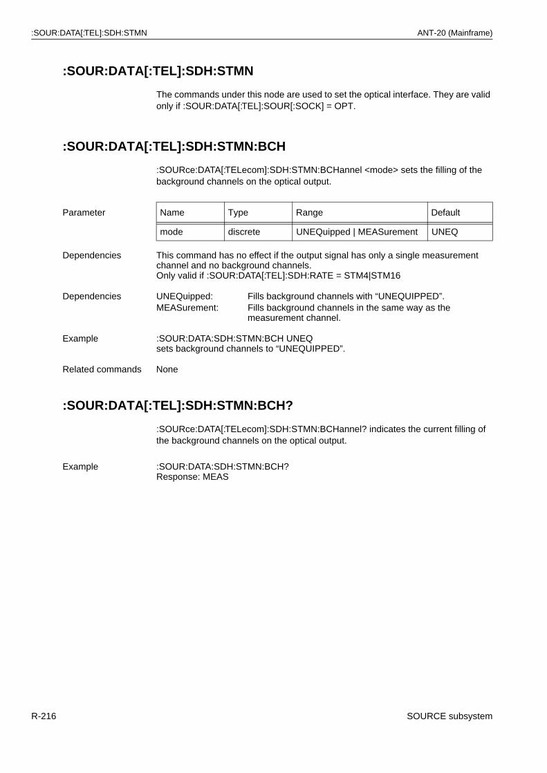
:SOUR:DATA[:TEL]:SDH:STMN ANT-20 (Mainframe)
:SOUR:DATA[:TEL]:SDH:STMN
The commands under this node are used to set the optical interface. They are valid only if :SOUR:DATA[:TEL]:SOUR[:SOCK] = OPT.
:SOUR:DATA[:TEL]:SDH:STMN:BCH
:SOURce:DATA[:TELecom]:SDH:STMN:BCHannel <mode> sets the filling of the background channels on the optical output.
:SOUR:DATA[:TEL]:SDH:STMN:BCH?
:SOURce:DATA[:TELecom]:SDH:STMN:BCHannel? indicates the current filling of the background channels on the optical output.
Parameter Name Type Range Default
mode discrete UNEQuipped | MEASurement UNEQ
Dependencies This command has no effect if the output signal has only a single measurement channel and no background channels.Only valid if :SOUR:DATA[:TEL]:SDH:RATE = STM4|STM16
Dependencies UNEQuipped: Fills background channels with “UNEQUIPPED”.MEASurement: Fills background channels in the same way as the
measurement channel.
Example :SOUR:DATA:SDH:STMN:BCH UNEQsets background channels to “UNEQUIPPED”.
Related commands None
Example :SOUR:DATA:SDH:STMN:BCH?Response: MEAS
R-216 SOURCE subsystem
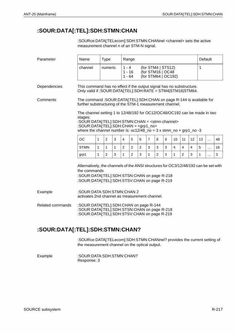
ANT-20 (Mainframe) :SOUR:DATA[:TEL]:SDH:STMN:CHAN
:SOUR:DATA[:TEL]:SDH:STMN:CHAN
:SOURce:DATA[:TELecom]:SDH:STMN:CHANnel <channel> sets the active measurement channel n of an STM-N signal.
Alternatively, the channels of the ANSI structures for OC3/12/48/192 can be set with the commands:SOUR:DATA[:TEL]:SDH:STSN:CHAN on page R-218:SOUR:DATA[:TEL]:SDH:STSV:CHAN on page R-219
:SOUR:DATA[:TEL]:SDH:STMN:CHAN?
:SOURce:DATA[:TELecom]:SDH:STMN:CHANnel? provides the current setting of the measurement channel on the optical output.
Parameter Name Type Range Default
channel numeric 1 - 41 - 161 - 64
(for STM4 | STS12)(for STM16 | OC48(for STM64 | OC192)
1
Dependencies This command has no effect if the output signal has no substructure.Only valid if :SOUR:DATA[:TEL]:SDH:RATE = STM4|STM16|STM64.
Comments The command :SOUR:DATA[:TEL]:SDH:CHAN on page R-144 is available for further substructuring of the STM-1 measurement channel.
The channel setting 1 to 12/48/192 for OC12/OC48/OC192 can be made in two stages::SOUR:DATA[:TEL]:SDH:STMN:CHAN = <stmn-channel> :SOUR:DATA[:TEL]:SDH:CHAN = <grp1_no>where the channel number is: oc12/48_no = 3 x stmn_no + grp1_no -3
OC 1 2 3 4 5 6 7 8 9 10 11 12 13 … 48
STMN 1 1 1 2 2 2 3 3 3 4 4 4 5 … 16
grp1 1 2 3 1 2 3 1 2 3 1 2 3 1 … 3
Example :SOUR:DATA:SDH:STMN:CHAN 2activates 2nd channel as measurement channel.
Related commands :SOUR:DATA[:TEL]:SDH:CHAN on page R-144:SOUR:DATA[:TEL]:SDH:STSN:CHAN on page R-218:SOUR:DATA[:TEL]:SDH:STSV:CHAN on page R-219
Example :SOUR:DATA:SDH:STMN:CHAN?Response: 3
SOURCE subsystem R-217
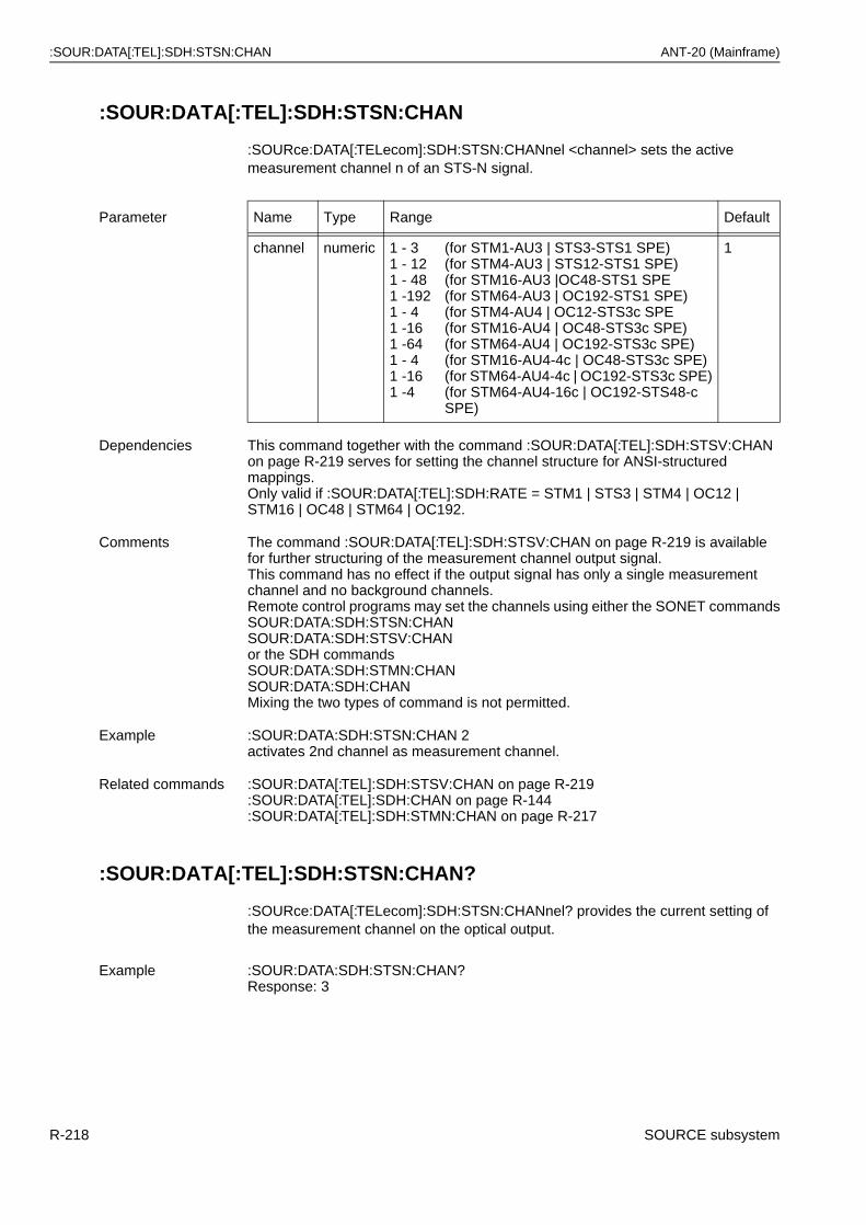
:SOUR:DATA[:TEL]:SDH:STSN:CHAN ANT-20 (Mainframe)
:SOUR:DATA[:TEL]:SDH:STSN:CHAN
:SOURce:DATA[:TELecom]:SDH:STSN:CHANnel <channel> sets the active measurement channel n of an STS-N signal.
:SOUR:DATA[:TEL]:SDH:STSN:CHAN?
:SOURce:DATA[:TELecom]:SDH:STSN:CHANnel? provides the current setting of the measurement channel on the optical output.
Parameter Name Type Range Default
channel numeric 1 - 31 - 121 - 481 -1921 - 41 -161 -641 - 41 -161 -4
(for STM1-AU3 | STS3-STS1 SPE)(for STM4-AU3 | STS12-STS1 SPE)(for STM16-AU3 |OC48-STS1 SPE(for STM64-AU3 | OC192-STS1 SPE)(for STM4-AU4 | OC12-STS3c SPE(for STM16-AU4 | OC48-STS3c SPE)(for STM64-AU4 | OC192-STS3c SPE)(for STM16-AU4-4c | OC48-STS3c SPE)(for STM64-AU4-4c | OC192-STS3c SPE)(for STM64-AU4-16c | OC192-STS48-c SPE)
1
Dependencies This command together with the command :SOUR:DATA[:TEL]:SDH:STSV:CHAN on page R-219 serves for setting the channel structure for ANSI-structured mappings.Only valid if :SOUR:DATA[:TEL]:SDH:RATE = STM1 | STS3 | STM4 | OC12 | STM16 | OC48 | STM64 | OC192.
Comments The command :SOUR:DATA[:TEL]:SDH:STSV:CHAN on page R-219 is available for further structuring of the measurement channel output signal.This command has no effect if the output signal has only a single measurement channel and no background channels.Remote control programs may set the channels using either the SONET commandsSOUR:DATA:SDH:STSN:CHANSOUR:DATA:SDH:STSV:CHANor the SDH commandsSOUR:DATA:SDH:STMN:CHANSOUR:DATA:SDH:CHANMixing the two types of command is not permitted.
Example :SOUR:DATA:SDH:STSN:CHAN 2activates 2nd channel as measurement channel.
Related commands :SOUR:DATA[:TEL]:SDH:STSV:CHAN on page R-219:SOUR:DATA[:TEL]:SDH:CHAN on page R-144:SOUR:DATA[:TEL]:SDH:STMN:CHAN on page R-217
Example :SOUR:DATA:SDH:STSN:CHAN?Response: 3
R-218 SOURCE subsystem
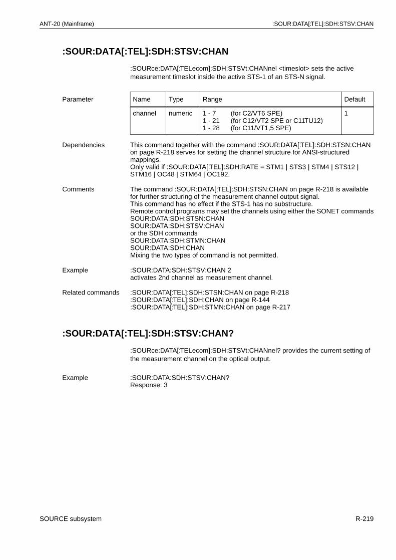
ANT-20 (Mainframe) :SOUR:DATA[:TEL]:SDH:STSV:CHAN
:SOUR:DATA[:TEL]:SDH:STSV:CHAN
:SOURce:DATA[:TELecom]:SDH:STSVt:CHANnel <timeslot> sets the active measurement timeslot inside the active STS-1 of an STS-N signal.
:SOUR:DATA[:TEL]:SDH:STSV:CHAN?
:SOURce:DATA[:TELecom]:SDH:STSVt:CHANnel? provides the current setting of the measurement channel on the optical output.
Parameter Name Type Range Default
channel numeric 1 - 71 - 211 - 28
(for C2/VT6 SPE)(for C12/VT2 SPE or C11TU12)(for C11/VT1,5 SPE)
1
Dependencies This command together with the command :SOUR:DATA[:TEL]:SDH:STSN:CHAN on page R-218 serves for setting the channel structure for ANSI-structured mappings.Only valid if :SOUR:DATA[:TEL]:SDH:RATE = STM1 | STS3 | STM4 | STS12 | STM16 | OC48 | STM64 | OC192.
Comments The command :SOUR:DATA[:TEL]:SDH:STSN:CHAN on page R-218 is available for further structuring of the measurement channel output signal.This command has no effect if the STS-1 has no substructure.Remote control programs may set the channels using either the SONET commandsSOUR:DATA:SDH:STSN:CHANSOUR:DATA:SDH:STSV:CHANor the SDH commandsSOUR:DATA:SDH:STMN:CHANSOUR:DATA:SDH:CHANMixing the two types of command is not permitted.
Example :SOUR:DATA:SDH:STSV:CHAN 2activates 2nd channel as measurement channel.
Related commands :SOUR:DATA[:TEL]:SDH:STSN:CHAN on page R-218:SOUR:DATA[:TEL]:SDH:CHAN on page R-144:SOUR:DATA[:TEL]:SDH:STMN:CHAN on page R-217
Example :SOUR:DATA:SDH:STSV:CHAN?Response: 3
SOURCE subsystem R-219
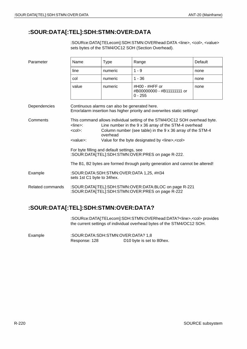
:SOUR:DATA[:TEL]:SDH:STMN:OVER:DATA ANT-20 (Mainframe)
:SOUR:DATA[:TEL]:SDH:STMN:OVER:DATA
:SOURce:DATA[:TELecom]:SDH:STMN:OVERhead:DATA <line>, <col>, <value> sets bytes of the STM4/OC12 SOH (Section Overhead).
:SOUR:DATA[:TEL]:SDH:STMN:OVER:DATA?
:SOURce:DATA[:TELecom]:SDH:STMN:OVERhead:DATA?<line>,<col> provides the current settings of individual overhead bytes of the STM4/OC12 SOH.
Parameter Name Type Range Default
line numeric 1 - 9 none
col numeric 1 - 36 none
value numeric #H00 - #HFF or#B00000000 - #B11111111 or 0 - 255
none
Dependencies Continuous alarms can also be generated here.Error/alarm insertion has higher priority and overwrites static settings!
Comments This command allows individual setting of the STM4/OC12 SOH overhead byte.<line>: Line number in the 9 x 36 array of the STM-4 overhead<col>: Column number (see table) in the 9 x 36 array of the STM-4
overhead<value>: Value for the byte designated by <line>,<col>
For byte filling and default settings, see:SOUR:DATA[:TEL]:SDH:STMN:OVER:PRES on page R-222.
The B1, B2 bytes are formed through parity generation and cannot be altered!
Example :SOUR:DATA:SDH:STMN:OVER:DATA 1,25, #H34sets 1st C1 byte to 34hex.
Related commands :SOUR:DATA[:TEL]:SDH:STMN:OVER:DATA:BLOC on page R-221:SOUR:DATA[:TEL]:SDH:STMN:OVER:PRES on page R-222
Example :SOUR:DATA:SDH:STMN:OVER:DATA? 1,8Response: 128 D10 byte is set to 80hex.
R-220 SOURCE subsystem
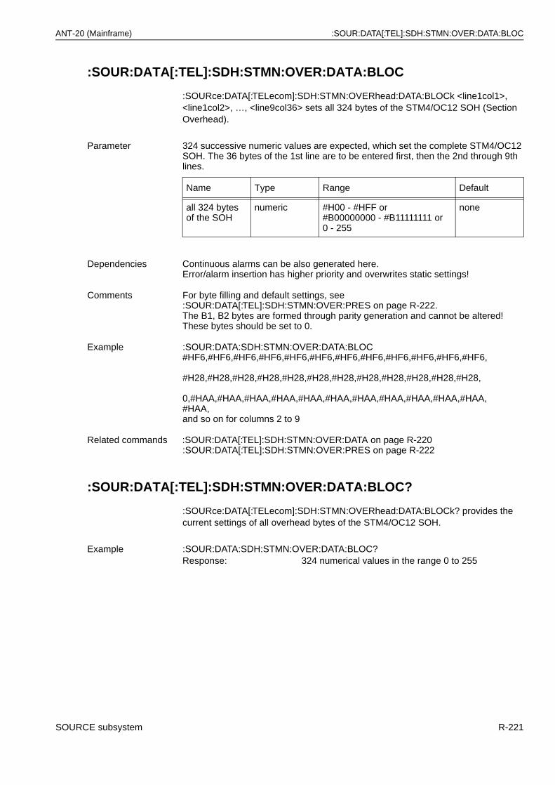
ANT-20 (Mainframe) :SOUR:DATA[:TEL]:SDH:STMN:OVER:DATA:BLOC
:SOUR:DATA[:TEL]:SDH:STMN:OVER:DATA:BLOC
:SOURce:DATA[:TELecom]:SDH:STMN:OVERhead:DATA:BLOCk <line1col1>, <line1col2>, …, <line9col36> sets all 324 bytes of the STM4/OC12 SOH (Section Overhead).
:SOUR:DATA[:TEL]:SDH:STMN:OVER:DATA:BLOC?
:SOURce:DATA[:TELecom]:SDH:STMN:OVERhead:DATA:BLOCk? provides the current settings of all overhead bytes of the STM4/OC12 SOH.
Parameter 324 successive numeric values are expected, which set the complete STM4/OC12 SOH. The 36 bytes of the 1st line are to be entered first, then the 2nd through 9th lines.
Name Type Range Default
all 324 bytes of the SOH
numeric #H00 - #HFF or#B00000000 - #B11111111 or 0 - 255
none
Dependencies Continuous alarms can be also generated here.Error/alarm insertion has higher priority and overwrites static settings!
Comments For byte filling and default settings, see:SOUR:DATA[:TEL]:SDH:STMN:OVER:PRES on page R-222.The B1, B2 bytes are formed through parity generation and cannot be altered!These bytes should be set to 0.
Example :SOUR:DATA:SDH:STMN:OVER:DATA:BLOC#HF6,#HF6,#HF6,#HF6,#HF6,#HF6,#HF6,#HF6,#HF6,#HF6,#HF6,#HF6,
#H28,#H28,#H28,#H28,#H28,#H28,#H28,#H28,#H28,#H28,#H28,#H28,
0,#HAA,#HAA,#HAA,#HAA,#HAA,#HAA,#HAA,#HAA,#HAA,#HAA,#HAA,#HAA,and so on for columns 2 to 9
Related commands :SOUR:DATA[:TEL]:SDH:STMN:OVER:DATA on page R-220:SOUR:DATA[:TEL]:SDH:STMN:OVER:PRES on page R-222
Example :SOUR:DATA:SDH:STMN:OVER:DATA:BLOC?Response: 324 numerical values in the range 0 to 255
SOURCE subsystem R-221
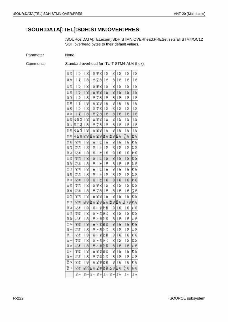
:SOUR:DATA[:TEL]:SDH:STMN:OVER:PRES ANT-20 (Mainframe)
:SOUR:DATA[:TEL]:SDH:STMN:OVER:PRES
:SOURce:DATA[:TELecom]:SDH:STMN:OVERhead:PRESet sets all STM4/OC12 SOH overhead bytes to their default values.
Parameter None
Comments Standard overhead for ITU-T STM4-AU4 (hex):co
l 1
col
2co
l 3
col
4co
l5
col
6co
l7
col
8co
l9
col
10co
l 11
col
12co
l 13
col
14co
l 15
col
16co
l 17
col
18co
l 19
col
20co
l 21
col
22co
l 23
col
24co
l 25
col
26co
l 27
col
28co
l 29
col
30co
l 31
col
32co
l 33
col
34co
l 35
col
36
line 1
A1
F6
A1
F6
A1
F6
A1
F6
A1
F6
A1
F6
A1
F6
A1
F6
A1
F6
A1
F6
A1
F6
A1
F6
A2
28A
228
A2
28A
228
A2
28A
228
A2
28A
228
A2
28A
228
A2
28A
228
J0 C1
01
Z0
C1
AA
Z0
C1
AA
Z0
C1
AA
–– AA
–– AA
–– AA
–– AA
–– AA
–– AA
–– AA
–– AA
line 2
B1
XX
–– 00–– 00
–– 00–– 00
–– 00–– 00
–– 00–– 00
–– 00–– 00
–– 00E
100
–– 00–– 00
–– 00–– 00
–– 00–– 00
–– 00–– 00
–– 00–– 00
–– 00F
100
–– 00–– 00
–– 00–– 00
–– 00–– 00
–– 00–– 00
–– 00–– 00
–– 00lin
e 3D
100
–– 00–– 00
–– 00–– 00
–– 00–– 00
–– 00–– 00
–– 00–– 00
–– 00D
200
–– 00–– 00
–– 00–– 00
–– 00–– 00
–– 00–– 00
–– 00–– 00
–– 00D
300
–– 00–– 00
–– 00–– 00
–– 00–– 00
–– 00–– 00
–– 00–– 00
–– 00lin
e 4H
168
H1
68H
168
H1
68Y 9B
Y 9BY 9B
Y 9BY 9B
Y 9BY 9B
Y 9BH
200
H2
00H
200
H2
00–– FF
–– FF
–– FF
–– FF
–– FF
–– FF
–– FF
–– FF
H3
00H
300
H3
00H
300
H3
00H
300
H3
00H
300
H3
00H
300
H3
00H
300
line 5
B2
XX
B2
XX
B2
XX
B2
XX
B2
XX
B2
XX
B2
XX
B2
XX
B2
XX
B2
XX
B2
XX
B2
XX
K1
00–– 00
–– 00–– 00
–– 00–– 00
–– 00–– 00
–– 00–– 00
–– 00–– 00
K2
00–– 00
–– 00–– 00
–– 00–– 00
–– 00–– 00
–– 00–– 00
–– 00–– 00
line 6
D4
00–– 00
–– 00–– 00
–– 00–– 00
–– 00–– 00
–– 00–– 00
–– 00–– 00
D5
00–– 00
–– 00–– 00
–– 00–– 00
–– 00–– 00
–– 00–– 00
–– 00–– 00
D6
00–– 00
–– 00–– 00
–– 00–– 00
–– 00–– 00
–– 00–– 00
–– 00–– 00
line 7
D7
00–– 00
–– 00–– 00
–– 00–– 00
–– 00–– 00
–– 00–– 00
–– 00–– 00
D8
00–– 00
–– 00–– 00
–– 00–– 00
–– 00–– 00
–– 00–– 00
–– 00–– 00
D9
00–– 00
–– 00–– 00
–– 00–– 00
–– 00–– 00
–– 00–– 00
–– 00–– 00
line 8
D10 00
–– 00–– 00
–– 00–– 00
–– 00–– 00
–– 00–– 00
–– 00–– 00
–– 00
D1 1 00
–– 00–– 00
–– 00–– 00
–– 00–– 00
–– 00–– 00
–– 00–– 00
–– 00D
12 00–– 00
–– 00–– 00
–– 00–– 00
–– 00–– 00
–– 00–– 00
–– 00–– 00
line 9
S1
00Z
100
Z1
00Z
100
Z1
00Z
100
Z1
00Z
100
Z1
00Z
100
Z1
00Z
100
Z2
00Z
200
M1
00Z
200
Z2
00Z
200
Z2
00Z
200
Z2
00Z
200
Z2
00Z
200
E2
00–– 00
–– 00–– 00
–– 00–– 00
–– 00–– 00
–– 00–– 00
–– 00–– 00
R-222 SOURCE subsystem
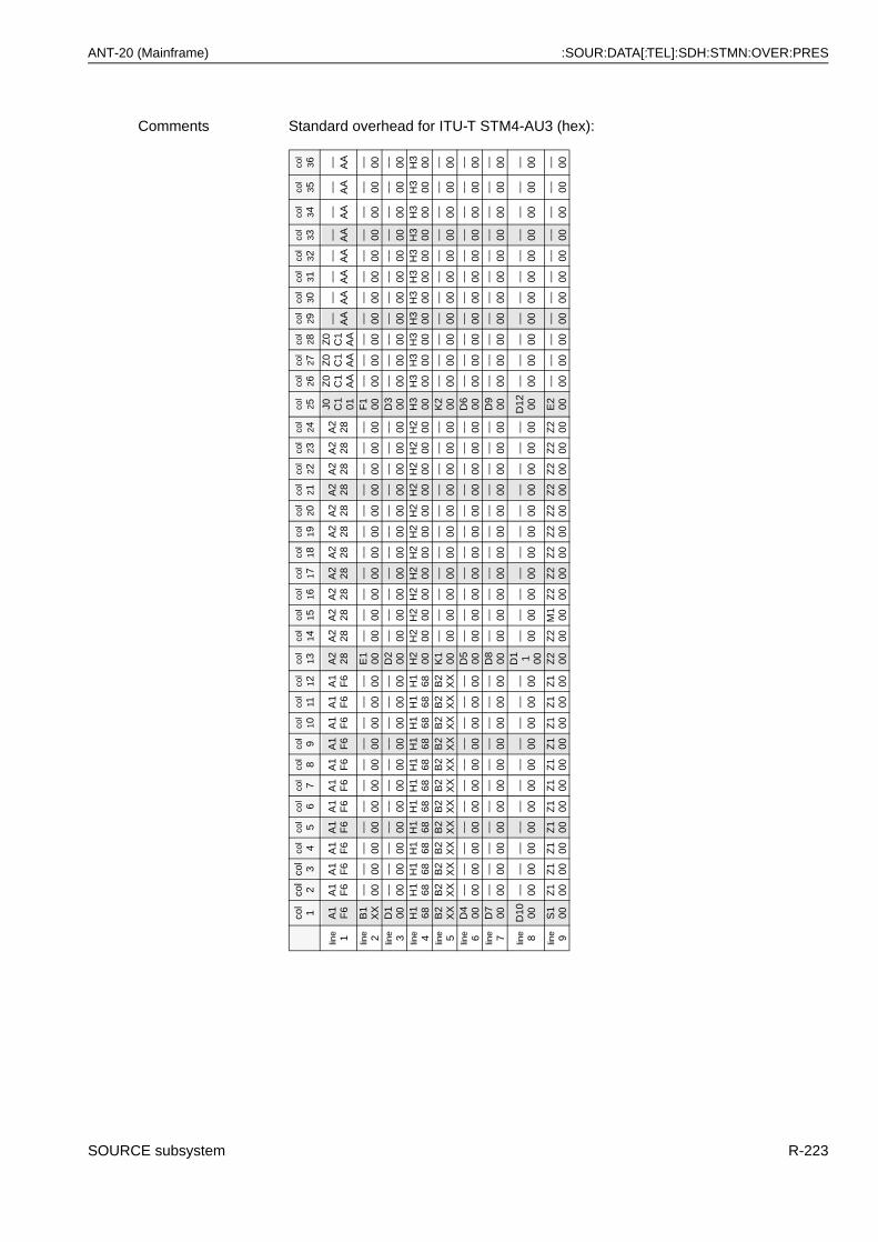
ANT-20 (Mainframe) :SOUR:DATA[:TEL]:SDH:STMN:OVER:PRES
Comments Standard overhead for ITU-T STM4-AU3 (hex):
col
1co
l 2
col
3co
l4
col
5co
l6
col
7co
l8
col
9co
l 10
col
11co
l 12
col
13co
l 14
col
15co
l 16
col
17co
l 18
col
19co
l 20
col
21co
l 22
col
23co
l 24
col
25co
l 26
col
27co
l 28
col
29co
l 30
col
31co
l 32
col
33co
l 34
col
35co
l 36
line 1
A1
F6
A1
F6
A1
F6
A1
F6
A1
F6
A1
F6
A1
F6
A1
F6
A1
F6
A1
F6
A1
F6
A1
F6
A2
28A
228
A2
28A
228
A2
28A
228
A2
28A
228
A2
28A
228
A2
28A
228
J0 C1
01
Z0
C1
AA
Z0
C1
AA
Z0
C1
AA
–– AA
–– AA
–– AA
–– AA
–– AA
–– AA
–– AA
–– AA
line 2
B1
XX
–– 00–– 00
–– 00–– 00
–– 00–– 00
–– 00–– 00
–– 00–– 00
–– 00E
100
–– 00–– 00
–– 00–– 00
–– 00–– 00
–– 00–– 00
–– 00–– 00
–– 00F
100
–– 00–– 00
–– 00–– 00
–– 00–– 00
–– 00–– 00
–– 00–– 00
–– 00lin
e 3D
100
–– 00–– 00
–– 00–– 00
–– 00–– 00
–– 00–– 00
–– 00–– 00
–– 00D
200
–– 00–– 00
–– 00–– 00
–– 00–– 00
–– 00–– 00
–– 00–– 00
–– 00D
300
–– 00–– 00
–– 00–– 00
–– 00–– 00
–– 00–– 00
–– 00–– 00
–– 00lin
e 4H
168
H1
68H
168
H1
68H
168
H1
68H
168
H1
68H
168
H1
68H
168
H1
68H
200
H2
00H
200
H2
00H
200
H2
00H
200
H2
00H
200
H2
00H
200
H2
00H
300
H3
00H
300
H3
00H
300
H3
00H
300
H3
00H
300
H3
00H
300
H3
00lin
e 5B
2X
XB
2X
XB
2X
XB
2X
XB
2X
XB
2X
XB
2X
XB
2X
XB
2X
XB
2X
XB
2X
XB
2X
XK
100
–– 00–– 00
–– 00–– 00
–– 00–– 00
–– 00–– 00
–– 00–– 00
–– 00K
200
–– 00–– 00
–– 00–– 00
–– 00–– 00
–– 00–– 00
–– 00–– 00
–– 00lin
e 6D
400
–– 00–– 00
–– 00–– 00
–– 00–– 00
–– 00–– 00
–– 00–– 00
–– 00D
500
–– 00–– 00
–– 00–– 00
–– 00–– 00
–– 00–– 00
–– 00–– 00
–– 00D
600
–– 00–– 00
–– 00–– 00
–– 00–– 00
–– 00–– 00
–– 00–– 00
–– 00lin
e 7D
700
–– 00–– 00
–– 00–– 00
–– 00–– 00
–– 00–– 00
–– 00–– 00
–– 00D
800
–– 00–– 00
–– 00–– 00
–– 00–– 00
–– 00–– 00
–– 00–– 00
–– 00D
900
–– 00–– 00
–– 00–– 00
–– 00–– 00
–– 00–– 00
–– 00–– 00
–– 00
line 8
D10 00
–– 00–– 00
–– 00–– 00
–– 00–– 00
–– 00–– 00
–– 00–– 00
–– 00
D1 1 00
–– 00–– 00
–– 00–– 00
–– 00–– 00
–– 00–– 00
–– 00–– 00
–– 00D
12 00–– 00
–– 00–– 00
–– 00–– 00
–– 00–– 00
–– 00–– 00
–– 00–– 00
line 9
S1
00Z
100
Z1
00Z
100
Z1
00Z
100
Z1
00Z
100
Z1
00Z
100
Z1
00Z
100
Z2
00Z
200
M1
00Z
200
Z2
00Z
200
Z2
00Z
200
Z2
00Z
200
Z2
00Z
200
E2
00–– 00
–– 00–– 00
–– 00–– 00
–– 00–– 00
–– 00–– 00
–– 00–– 00
SOURCE subsystem R-223
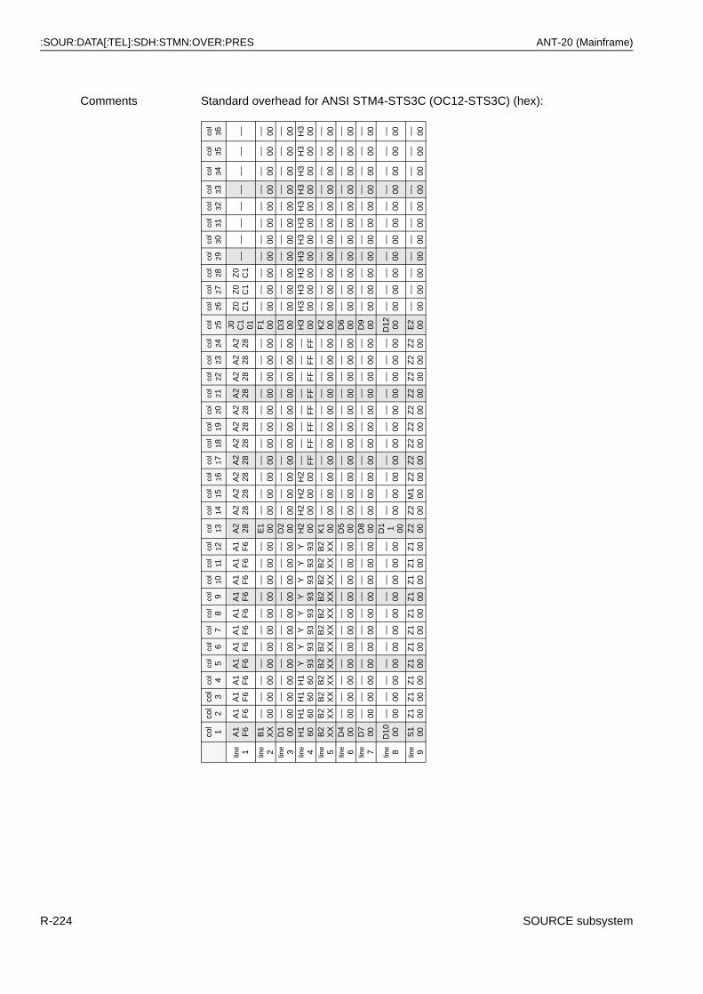
:SOUR:DATA[:TEL]:SDH:STMN:OVER:PRES ANT-20 (Mainframe)
Comments Standard overhead for ANSI STM4-STS3C (OC12-STS3C) (hex):
col
1co
l 2
col
3co
l4
col
5co
l6
col
7co
l8
col
9co
l 10
col
11co
l 12
col
13co
l 14
col
15co
l 16
col
17co
l 18
col
19co
l 20
col
21co
l 22
col
23co
l 24
col
25co
l 26
col
27co
l 28
col
29co
l 30
col
31co
l 32
col
33co
l 34
col
35co
l 36
line 1
A1
F6
A1
F6
A1
F6
A1
F6
A1
F6
A1
F6
A1
F6
A1
F6
A1
F6
A1
F6
A1
F6
A1
F6
A2
28A
228
A2
28A
228
A2
28A
228
A2
28A
228
A2
28A
228
A2
28A
228
J0 C1
01
Z0
C1
Z0
C1
Z0
C1
––––
––––
––––
––––
line 2
B1
XX
–– 00–– 00
–– 00–– 00
–– 00–– 00
–– 00–– 00
–– 00–– 00
–– 00E
100
–– 00–– 00
–– 00–– 00
–– 00–– 00
–– 00–– 00
–– 00–– 00
–– 00F
100
–– 00–– 00
–– 00–– 00
–– 00–– 00
–– 00–– 00
–– 00–– 00
–– 00lin
e 3D
100
–– 00–– 00
–– 00–– 00
–– 00–– 00
–– 00–– 00
–– 00–– 00
–– 00D
200
–– 00–– 00
–– 00–– 00
–– 00–– 00
–– 00–– 00
–– 00–– 00
–– 00D
300
–– 00–– 00
–– 00–– 00
–– 00–– 00
–– 00–– 00
–– 00–– 00
–– 00lin
e 4H
160
H1
60H
160
H1
60Y 93
Y 93Y 93
Y 93Y 93
Y 93Y 93
Y 93H
200
H2
00H
200
H2
00–– F
F–– F
F–– F
F–– F
F–– F
F–– F
F–– F
F–– F
FH
300
H3
00H
300
H3
00H
300
H3
00H
300
H3
00H
300
H3
00H
300
H3
00lin
e 5B
2X
XB
2X
XB
2X
XB
2X
XB
2X
XB
2X
XB
2X
XB
2X
XB
2X
XB
2X
XB
2X
XB
2X
XK
100
–– 00–– 00
–– 00–– 00
–– 00–– 00
–– 00–– 00
–– 00–– 00
–– 00K
200
–– 00–– 00
–– 00–– 00
–– 00–– 00
–– 00–– 00
–– 00–– 00
–– 00lin
e 6D
400
–– 00–– 00
–– 00–– 00
–– 00–– 00
–– 00–– 00
–– 00–– 00
–– 00D
500
–– 00–– 00
–– 00–– 00
–– 00–– 00
–– 00–– 00
–– 00–– 00
–– 00D
600
–– 00–– 00
–– 00–– 00
–– 00–– 00
–– 00–– 00
–– 00–– 00
–– 00lin
e 7D
700
–– 00–– 00
–– 00–– 00
–– 00–– 00
–– 00–– 00
–– 00–– 00
–– 00D
800
–– 00–– 00
–– 00–– 00
–– 00–– 00
–– 00–– 00
–– 00–– 00
–– 00D
900
–– 00–– 00
–– 00–– 00
–– 00–– 00
–– 00–– 00
–– 00–– 00
–– 00
line 8
D10 00
–– 00–– 00
–– 00–– 00
–– 00–– 00
–– 00–– 00
–– 00–– 00
–– 00
D1 1 00
–– 00–– 00
–– 00–– 00
–– 00–– 00
–– 00–– 00
–– 00–– 00
–– 00D
12 00–– 00
–– 00–– 00
–– 00–– 00
–– 00–– 00
–– 00–– 00
–– 00–– 00
line 9
S1
00Z
100
Z1
00Z
100
Z1 00
Z1
00Z
1 00Z
100
Z1 00
Z1
00Z
1 00Z
100
Z2
00Z
200
M1
00Z
200
Z2
00Z
200
Z2
00Z
200
Z2
00Z
200
Z2
00Z
200
E2
00–– 00
–– 00–– 00
–– 00–– 00
–– 00–– 00
–– 00–– 00
–– 00–– 00
R-224 SOURCE subsystem
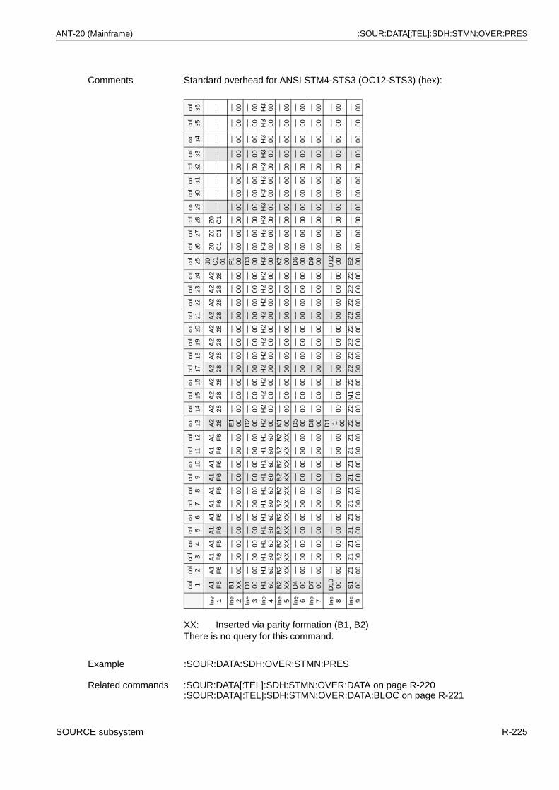
ANT-20 (Mainframe) :SOUR:DATA[:TEL]:SDH:STMN:OVER:PRES
Comments Standard overhead for ANSI STM4-STS3 (OC12-STS3) (hex):
XX: Inserted via parity formation (B1, B2)There is no query for this command.
Example :SOUR:DATA:SDH:OVER:STMN:PRES
Related commands :SOUR:DATA[:TEL]:SDH:STMN:OVER:DATA on page R-220:SOUR:DATA[:TEL]:SDH:STMN:OVER:DATA:BLOC on page R-221
col
1co
l 2
col
3co
l4
col
5co
l6
col
7co
l8
col
9co
l 10
col
11co
l 12
col
13co
l 14
col
15co
l 16
col
17co
l 18
col
19co
l 20
col
21co
l 22
col
23co
l 24
col
25co
l 26
col
27co
l 28
col
29co
l 30
col
31co
l 32
col
33co
l 34
col
35co
l 36
line 1
A1
F6
A1
F6
A1
F6
A1
F6
A1
F6
A1
F6
A1
F6
A1
F6
A1
F6
A1
F6
A1
F6
A1
F6
A2
28A
228
A2
28A
228
A2
28A
228
A2
28A
228
A2
28A
228
A2
28A
228
J0 C1
01
Z0
C1
Z0
C1
Z0
C1
––––
––––
––––
––––
line 2
B1
XX
–– 00–– 00
–– 00–– 00
–– 00–– 00
–– 00–– 00
–– 00–– 00
–– 00E
100
–– 00–– 00
–– 00–– 00
–– 00–– 00
–– 00–– 00
–– 00–– 00
–– 00F
100
–– 00–– 00
–– 00–– 00
–– 00–– 00
–– 00–– 00
–– 00–– 00
–– 00lin
e 3D
100
–– 00–– 00
–– 00–– 00
–– 00–– 00
–– 00–– 00
–– 00–– 00
–– 00D
200
–– 00–– 00
–– 00–– 00
–– 00–– 00
–– 00–– 00
–– 00–– 00
–– 00D
300
–– 00–– 00
–– 00–– 00
–– 00–– 00
–– 00–– 00
–– 00–– 00
–– 00lin
e 4H
160
H1
60H
160
H1
60H
160
H1
60H
160
H1
60H
160
H1
60H
160
H1
60H
200
H2
00H
200
H2
00H
200
H2
00H
200
H2
00H
200
H2
00H
200
H2
00H
300
H3
00H
300
H3
00H
300
H3
00H
300
H3
00H
300
H3
00H
300
H3
00lin
e 5B
2X
XB
2X
XB
2X
XB
2X
XB
2X
XB
2X
XB
2X
XB
2X
XB
2X
XB
2X
XB
2X
XB
2X
XK
100
–– 00–– 00
–– 00–– 00
–– 00–– 00
–– 00–– 00
–– 00–– 00
–– 00K
200
–– 00–– 00
–– 00–– 00
–– 00–– 00
–– 00–– 00
–– 00–– 00
–– 00lin
e 6D
400
–– 00–– 00
–– 00–– 00
–– 00–– 00
–– 00–– 00
–– 00–– 00
–– 00D
500
–– 00–– 00
–– 00–– 00
–– 00–– 00
–– 00–– 00
–– 00–– 00
–– 00D
600
–– 00–– 00
–– 00–– 00
–– 00–– 00
–– 00–– 00
–– 00–– 00
–– 00lin
e 7D
700
–– 00–– 00
–– 00–– 00
–– 00–– 00
–– 00–– 00
–– 00–– 00
–– 00D
800
–– 00–– 00
–– 00–– 00
–– 00–– 00
–– 00–– 00
–– 00–– 00
–– 00D
900
–– 00–– 00
–– 00–– 00
–– 00–– 00
–– 00–– 00
–– 00–– 00
–– 00
line 8
D10 00
–– 00–– 00
–– 00–– 00
–– 00–– 00
–– 00–– 00
–– 00–– 00
–– 00
D1 1 00
–– 00–– 00
–– 00–– 00
–– 00–– 00
–– 00–– 00
–– 00–– 00
–– 00D
12 00–– 00
–– 00–– 00
–– 00–– 00
–– 00–– 00
–– 00–– 00
–– 00–– 00
line 9
S1
00Z
100
Z1
00Z
100
Z1
00Z
100
Z1
00Z
100
Z1
00Z
100
Z1
00Z
100
Z2
00Z
200
M1
00Z
200
Z2
00Z
200
Z2
00Z
200
Z2
00Z
200
Z2
00Z
200
E2
00–– 00
–– 00–– 00
–– 00–– 00
–– 00–– 00
–– 00–– 00
–– 00–– 00
SOURCE subsystem R-225
:SOUR:DATA[:TEL]:SDH:STMN:OVER:RDAT ANT-20 (Mainframe)
:SOUR:DATA[:TEL]:SDH:STMN:OVER:RDAT
:SOURce:DATA[:TELecom]:SDH:STMN:OVERhead:RDATa <line>, <col>, <value> selects the overhead bytes of the STM4 (OC12) SOH/TOH (Section/Transport Overhead) to be replaced.
:SOUR:DATA[:TEL]:SDH:STMN:OVER:RDAT?
:SOURce:DATA[:TELecom]:SDH:STMN:OVERhead:RDATa?<line>,<col> provides the current setting of the replaced overhead bytes of the STM4 (OC12) SOH/TOH (Section/Transport Overhead).
Parameter Name Type Range Default
line numeric 1 - 9 none
col numeric 1 - 36 none
value numeric 0 - 1 none
Dependencies Only valid if :SOUR:DATA[:TEL]:NEL = ADM.The B1, B2, M1 bytes are always terminated and reconstructed by this instrument and cannot be replaced in the way described here.
Comments In “Through” mode this command determines the bytes being switched through transparently by the receiver or the bytes being overwritten by the transmitter.<line>: Line number in the 9 x 36 array of the STM-4 (OC-12) overhead<col>: Column number (see table) in the 9 x 36 array of the STM-4
(OC12) overhead<value>: 0: Byte is taken from RX
1: Byte is replaced by the TX byte value set by:SOUR:DATA[:TEL]:SDH:STMN:OVER:DATA on page R-220
Example :SOUR:DATA:SDH:STMN:OVER:RDAT 1,25, 1C1 byte not from TX
Related commands :SOUR:DATA[:TEL]:SDH:STMN:OVER:DATA on page R-220:SOUR:DATA[:TEL]:SDH:STMN:OVER:DATA:BLOC on page R-221:SOUR:DATA[:TEL]:NEL on page R-86:SOUR:DATA[:TEL]:SDH:STMN:OVER:RDAT:BLOC on page R-227:SOUR:DATA[:TEL]:SDH:OVER[i]:RDAT on page R-182
Example :SOUR:DATA:SDH:STMN:OVER:RDAT? 13,8Response: 1 D11 is replaced.
R-226 SOURCE subsystem
ANT-20 (Mainframe) :SOUR:DATA[:TEL]:SDH:STMN:OVER:RDAT:BLOC
:SOUR:DATA[:TEL]:SDH:STMN:OVER:RDAT:BLOC
:SOURce:DATA[:TELecom]:SDH:STMN:OVERhead:RDATa:BLOCk <line1col1>, <line1col2>, …, <line9col36> selects the overhead bytes of the complete STM4 (OC12) SOH/TOH (Section/Transport Overhead) that are to be replaced.
Parameter 324 successive numeric values are expected, which set the complete STM4/OC12 SOH. The 36 bytes of the 1st line are to be entered first, then the 2nd through 9th lines.
Name Type Range Default
all 324 bytes of the SOH
numeric 0 - 1 none
Dependencies Only valid if :SOUR:DATA[:TEL]:NEL = ADM.The B1, B2, M1 bytes are always terminated and reconstructed by this instrument and cannot be replaced in the way described here. They must be set to 1.
Comments In “Through” mode this command determines the bytes being switched through transparently by the receiver or the bytes being overwritten by the transmitter.<values> 0: Byte is taken from RX
1: Byte is replaced by the TX byte value set by :SOUR:DATA[:TEL]:SDH:STMN:OVER:DATA on page R-220
Example :SOUR:DATA:SDH:STMN:OVER:RDAT:BLOC1,1,1,1,1,1,1,1,1,1,1,1,1,1,1,1,1,1,1,1,1,1,1,1,1,1,1,1,1,1,1,1,1,1,1,1,1,1,1,1,1,1,1,1,1,1,1,1,1,1,1,1,1,1,1,1,1,1,1,1,1,1,1,1,1,1,1,1,1,1,1,1,0,1,1,1,1,1,1,1,1,1,1,1,1,1,1,1,1,1,1,1,1,1,1,1,1,1,1,1,1,1,1,1,1,1,1,1,1,1,1,1,1,1,1,1,1,1,1,1,1,1,1,1,1,1,1,1,1,1,1,1,1,1,1,1,1,1,1,1,1,1,1,1,1,1,1,1,1,1,1,1,1,1,1,1,1,1,1,1,1,1,1,1,1,1,1,1,1,1,1,1,1,1,1,1,1,1,1,1,1,1,1,1,1,1,1,1,1,1,1,1,1,1,1,1,1,1,1,1,1,1,1,1,1,1,1,1,1,1,1,1,1,1,1,1,1,1,1,1,1,1,1,1,1,1,1,1,1,1,1,1,1,1,1,1,1,1,1,1,1,1,1,1,1,1,1,1,1,1,1,1,1,1,1,1,1,1,1,1,1,1,1,1,1,1,1,1,1,1,1,1,1,1,1,1,1,1,1,1,1,1,1,1,1,1,1,1,1,1,1,1,1,1,1,1,1,1,1,1,1,1,1,1,1,1,1,1,1,1,1,1,1,1,1,1,1,1,1,1,1,1,1,1replaces only the D1 byte.
Related commands :SOUR:DATA[:TEL]:SDH:STMN:OVER:DATA on page R-220:SOUR:DATA[:TEL]:SDH:STMN:OVER:DATA:BLOC on page R-221:SOUR:DATA[:TEL]:SDH:STMN:OVER:RDAT on page R-226:SOUR:DATA[:TEL]:NEL on page R-86:SOUR:DATA[:TEL]:SDH:OVER[i]:RDAT on page R-182
SOURCE subsystem R-227
:SOUR:DATA[:TEL]:SDH:STMN:OVER:RDAT:BLOC? ANT-20 (Mainframe)
:SOUR:DATA[:TEL]:SDH:STMN:OVER:RDAT:BLOC?
:SOURce:DATA[:TELecom]:SDH:STMN:OVERhead:RDATa:BLOCk? provides the current setting of the replaced overhead bytes of the complete STM4 (OC12) SOH/TOH (Section/Transport Overhead).
Example :SOUR:DATA:SDH:STMN:OVER:RDAT:BLOC?Response: 324 numerical values in the range 0 to 11,1,1,1,1,1,1,1,1,1,1,1,1,1,1,1,1,1,1,1,1,1,1,1,1,1,1,1,1,1,1,1,1,1,1,1,1,1,1,1,1,1,1,1,1,1,1,1,1,1,1,1,1,1,1,1,1,1,1,1,1,1,1,1,1,1,1,1,1,1,1,1,0,1,1,1,1,1,1,1,1,1,1,1,1,1,1,1,1,1,1,1,1,1,1,1,1,1,1,1,1,1,1,1,1,1,1,1,1,1,1,1,1,1,1,1,1,1,1,1,1,1,1,1,1,1,1,1,1,1,1,1,1,1,1,1,1,1,1,1,1,1,1,1,1,1,1,1,1,1,1,1,1,1,1,1,1,1,1,1,1,1,1,1,1,1,1,1,1,1,1,1,1,1,1,1,1,1,1,1,1,1,1,1,1,1,1,1,1,1,1,1,1,1,1,1,1,1,1,1,1,1,1,1,1,1,1,1,1,1,1,1,1,1,1,1,1,1,1,1,1,1,1,1,1,1,1,1,1,1,1,1,1,1,1,1,1,1,1,1,1,1,1,1,1,1,1,1,1,1,1,1,1,1,1,1,1,1,1,1,1,1,1,1,1,1,1,1,1,1,1,1,1,1,1,1,1,1,1,1,1,1,1,1,1,1,1,1,1,1,1,1,1,1,1,1,1,1,1,1,1,1,1,1,1,1,1,1,1,1,1,1,1,1,1,1,1,1,1,1,1,1,1,1if only the D1 byte is replaced.
R-228 SOURCE subsystem
ANT-20 (Mainframe) :SOUR:DATA[:TEL]:SDH:TRIB
:SOUR:DATA[:TEL]:SDH:TRIB
The commands in this command group determine the settings of all low path tributary units (TU-11, TU-12, TU-2, TU-3).
:SOUR:DATA[:TEL]:SDH:TRIB:BPOV:DATA
:SOURce:DATA[:TELecom]:SDH:TRIButary:BPOVerhead:DATA <byte>, <value> sets bytes of the VC12 POH (path overhead) of the background channels.
:SOUR:DATA[:TEL]:SDH:TRIB:BPOV:DATA?
:SOURce:DATA[:TELecom]:SDH:TRIButary:BPOVerhead:DATA? <byte> provides the current settings of individual VC12 POH (path overhead) bytes in the common background channels.
Parameter Name Type Range Default
byte discrete V5 | J2 | N2 | K4(Z6) none
value numeric #H00 - #HFF or#B00000000 - #B11111111 or 0 - 255For V5, only values from 0 - 63 are allowed
none
Dependencies None
Comments This command allows individual setting of the designated POH bytes in all background channels simultaneously.For <byte> = V5 only values for the bits 3 to 8 are allowed.
Example :SOUR:DATA:SDH:TRIB:BPOV:DATA N2, #H34 sets N2 byte to 34hex.
Related commands :SOUR:DATA[:TEL]:SDH:TRIB:BPOV:LPTR on page R-230:SOUR:DATA[:TEL]:SDH:TRIB:BPOV:DATA on page R-229:SOUR:DATA[:TEL]:SDH:TRIB:POV:DATA on page R-246
Example :SOUR:DATA:SDH:TRIB:BPOV:DATA? N2Response: 128 N2 byte is set to 80hex.
SOURCE subsystem R-229
:SOUR:DATA[:TEL]:SDH:TRIB:BPOV:LPTR ANT-20 (Mainframe)
:SOUR:DATA[:TEL]:SDH:TRIB:BPOV:LPTR
:SOURce:DATA[:TELecom]:SDH:
:BPOVerhead:LPTRace <mode>, <trace> determines the cyclical path trace string and mode in the J2 low path trace (J2 byte of the VC12 POH (path overhead)) of all background channels.
:SOUR:DATA[:TEL]:SDH:TRIB:BPOV:LPTR?
:SOURce:DATA[:TELecom]:SDH:TRIButary:BPOVerhead:LPTRace? provides the current setting of the J2 low path trace in the J2 byte of the VC12 POH (path overhead) of all background channels.
Parameter Name Type Range Default
mode discrete NONE | TRC16 TRC16
trace string Strings with a length from 1 to 15 bytes
“WG IDLE”
Dependencies None
Comments <mode> =NONE: Path trace is switched off. The J2 byte as set by
:SOUR:DATA[:TEL]:SDH:TRIB:BPOV:DATA on page R-229 is transmitted statically.
TRC16: The string of up to 15 characters is automatically completed forframe synchronization and error checking with the 16th byteusing CRC-7.
<trace>: All printable characters are allowed (7 bit ASCII). If the string is shorter than the maximum length, it is padded with blanks (20hex).Non-printing characters can be set using the UNIX shell conventions:
\n --> new line character\r --> CR character\b --> back space character\t --> TAB character\0 --> 0 HEX character\\ --> \ character\001 --> 01 HEX character in octal notation
Example :SOUR:DATA:SDH:TRIB:BPOV:LPTR TRC16,“Hello World”“Hello World” is transmitted cyclically in the J2 trace.
Related commands :SOUR:DATA[:TEL]:SDH:TRIB:POV:LPTR on page R-247:SOUR:DATA[:TEL]:SDH:TRIB:BPOV:DATA on page R-229
Example :SOUR:DATA:SDH:TRIB:BPOV:LPTR?Response: TRC16,“Hello World”for “Hello World” in the 16 byte trace.
R-230 SOURCE subsystem
ANT-20 (Mainframe) :SOUR:DATA[:TEL]:SDH:TRIB:BPOV:PRES
:SOUR:DATA[:TEL]:SDH:TRIB:BPOV:PRES
:SOURce:DATA[:TELecom]:SDH:TRIButary:BPOVerhead:PRESet sets all tributary overhead bytes (V5,J2,N2,K4(Z6)) of the background channels to their default values.
YYY = 010 (VC-12 A = for asynchronous operation)
YYY = 011 (VC-12 S = for bit-synchronous operation)
There is no query for this command.
Parameter None
Comments Standard overhead (binary):
POH bytes Pattern
V5
J2
N2
K4(Z6)
XX00YYY0
00
00
00
XX = LP-BIP error, generated internally Bits 1-2Other bit patterns:LP-REI (FEBE) fixed at “0” Bit 3RFI Bit 4Signal label (L1, L2, L3) Bits 5-7LP-RDI (FERF) Bit 8
Example :SOUR:DATA:SDH:TRIB:BPOV:PRES
Related commands :SOUR:DATA[:TEL]:SDH:TRIB:BPOV:DATA on page R-229:SOUR:DATA[:TEL]:SDH:TRIB:BPOV:LPTR on page R-230
SOURCE subsystem R-231
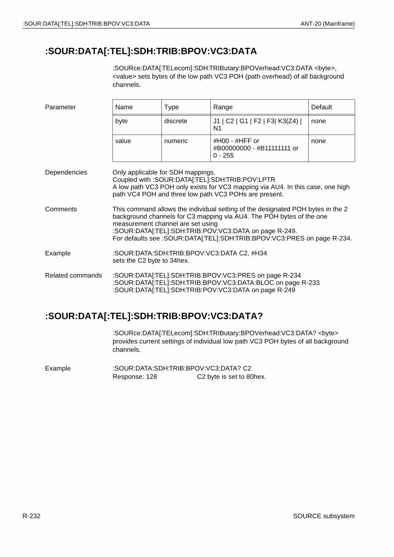
:SOUR:DATA[:TEL]:SDH:TRIB:BPOV:VC3:DATA ANT-20 (Mainframe)
:SOUR:DATA[:TEL]:SDH:TRIB:BPOV:VC3:DATA
:SOURce:DATA[:TELecom]:SDH:TRIButary:BPOVerhead:VC3:DATA <byte>, <value> sets bytes of the low path VC3 POH (path overhead) of all background channels.
:SOUR:DATA[:TEL]:SDH:TRIB:BPOV:VC3:DATA?
:SOURce:DATA[:TELecom]:SDH:TRIButary:BPOVerhead:VC3:DATA? <byte> provides current settings of individual low path VC3 POH bytes of all background channels.
Parameter Name Type Range Default
byte discrete J1 | C2 | G1 | F2 | F3| K3(Z4) | N1
none
value numeric #H00 - #HFF or#B00000000 - #B11111111 or0 - 255
none
Dependencies Only applicable for SDH mappings.Coupled with :SOUR:DATA[:TEL]:SDH:TRIB:POV:LPTRA low path VC3 POH only exists for VC3 mapping via AU4. In this case, one high path VC4 POH and three low path VC3 POHs are present.
Comments This command allows the individual setting of the designated POH bytes in the 2 background channels for C3 mapping via AU4. The POH bytes of the one measurement channel are set using :SOUR:DATA[:TEL]:SDH:TRIB:POV:VC3:DATA on page R-249.For defaults see :SOUR:DATA[:TEL]:SDH:TRIB:BPOV:VC3:PRES on page R-234.
Example :SOUR:DATA:SDH:TRIB:BPOV:VC3:DATA C2, #H34sets the C2 byte to 34hex.
Related commands :SOUR:DATA[:TEL]:SDH:TRIB:BPOV:VC3:PRES on page R-234:SOUR:DATA[:TEL]:SDH:TRIB:BPOV:VC3:DATA:BLOC on page R-233:SOUR:DATA[:TEL]:SDH:TRIB:POV:VC3:DATA on page R-249
Example :SOUR:DATA:SDH:TRIB:BPOV:VC3:DATA? C2Response: 128 C2 byte is set to 80hex.
R-232 SOURCE subsystem
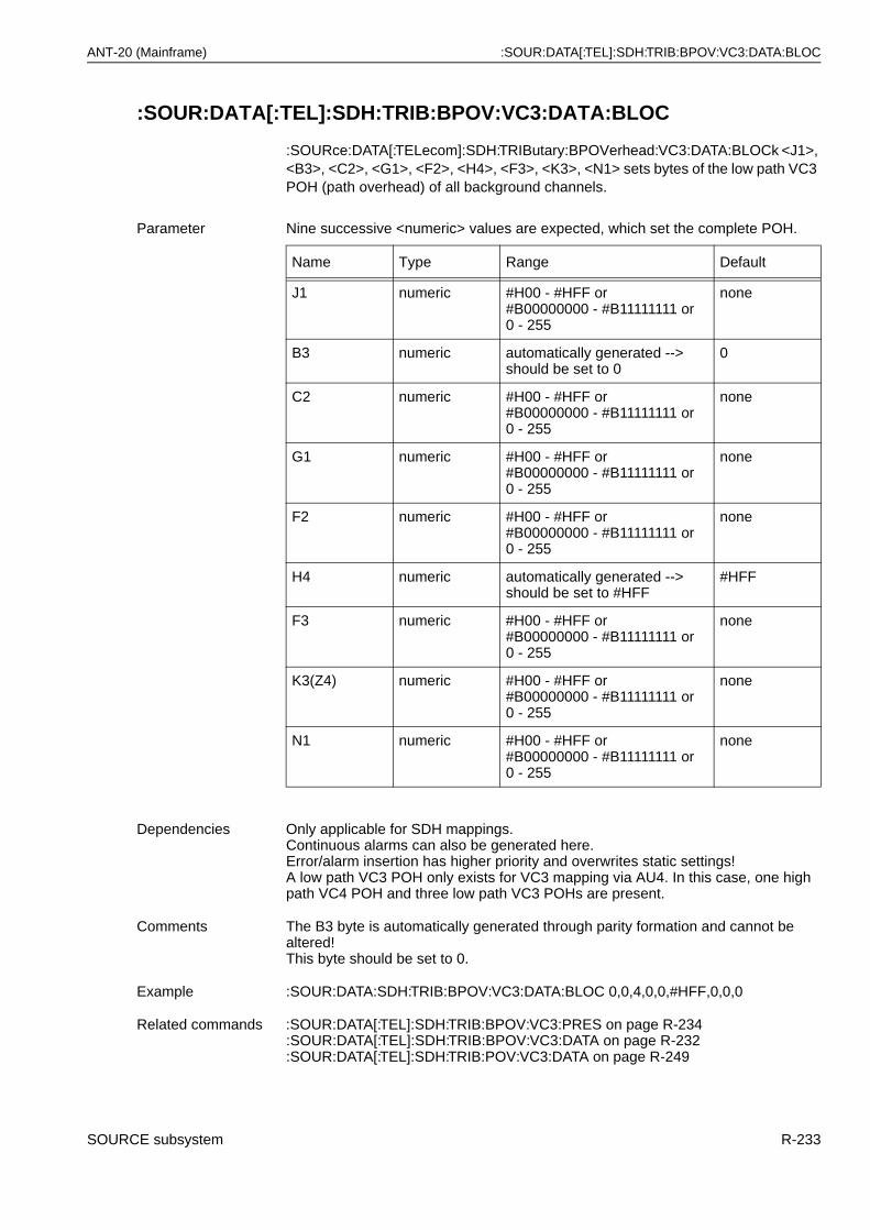
ANT-20 (Mainframe) :SOUR:DATA[:TEL]:SDH:TRIB:BPOV:VC3:DATA:BLOC
:SOUR:DATA[:TEL]:SDH:TRIB:BPOV:VC3:DATA:BLOC
:SOURce:DATA[:TELecom]:SDH:TRIButary:BPOVerhead:VC3:DATA:BLOCk <J1>, <B3>, <C2>, <G1>, <F2>, <H4>, <F3>, <K3>, <N1> sets bytes of the low path VC3 POH (path overhead) of all background channels.
Parameter Nine successive <numeric> values are expected, which set the complete POH.
Name Type Range Default
J1 numeric #H00 - #HFF or#B00000000 - #B11111111 or 0 - 255
none
B3 numeric automatically generated --> should be set to 0
0
C2 numeric #H00 - #HFF or#B00000000 - #B11111111 or 0 - 255
none
G1 numeric #H00 - #HFF or#B00000000 - #B11111111 or0 - 255
none
F2 numeric #H00 - #HFF or#B00000000 - #B11111111 or0 - 255
none
H4 numeric automatically generated --> should be set to #HFF
#HFF
F3 numeric #H00 - #HFF or#B00000000 - #B11111111 or 0 - 255
none
K3(Z4) numeric #H00 - #HFF or#B00000000 - #B11111111 or 0 - 255
none
N1 numeric #H00 - #HFF or#B00000000 - #B11111111 or 0 - 255
none
Dependencies Only applicable for SDH mappings.Continuous alarms can also be generated here.Error/alarm insertion has higher priority and overwrites static settings!A low path VC3 POH only exists for VC3 mapping via AU4. In this case, one high path VC4 POH and three low path VC3 POHs are present.
Comments The B3 byte is automatically generated through parity formation and cannot be altered!This byte should be set to 0.
Example :SOUR:DATA:SDH:TRIB:BPOV:VC3:DATA:BLOC 0,0,4,0,0,#HFF,0,0,0
Related commands :SOUR:DATA[:TEL]:SDH:TRIB:BPOV:VC3:PRES on page R-234:SOUR:DATA[:TEL]:SDH:TRIB:BPOV:VC3:DATA on page R-232:SOUR:DATA[:TEL]:SDH:TRIB:POV:VC3:DATA on page R-249
SOURCE subsystem R-233
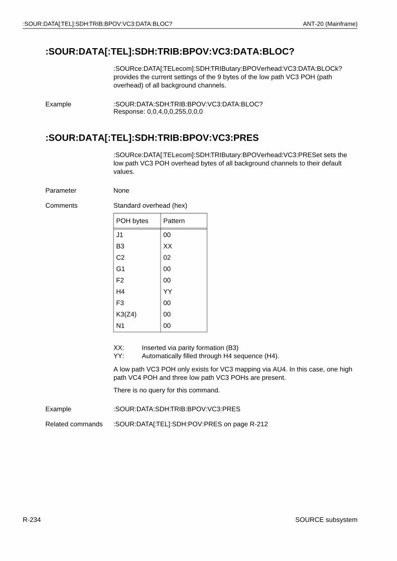
:SOUR:DATA[:TEL]:SDH:TRIB:BPOV:VC3:DATA:BLOC? ANT-20 (Mainframe)
:SOUR:DATA[:TEL]:SDH:TRIB:BPOV:VC3:DATA:BLOC?
:SOURce:DATA[:TELecom]:SDH:TRIButary:BPOVerhead:VC3:DATA:BLOCk? provides the current settings of the 9 bytes of the low path VC3 POH (path overhead) of all background channels.
:SOUR:DATA[:TEL]:SDH:TRIB:BPOV:VC3:PRES
:SOURce:DATA[:TELecom]:SDH:TRIButary:BPOVerhead:VC3:PRESet sets the low path VC3 POH overhead bytes of all background channels to their default values.
A low path VC3 POH only exists for VC3 mapping via AU4. In this case, one high path VC4 POH and three low path VC3 POHs are present.
There is no query for this command.
Example :SOUR:DATA:SDH:TRIB:BPOV:VC3:DATA:BLOC?Response: 0,0,4,0,0,255,0,0,0
Parameter None
Comments Standard overhead (hex)
POH bytes Pattern
J1
B3
C2
G1
F2
H4
F3
K3(Z4)
N1
00
XX
02
00
00
YY
00
00
00
XX: Inserted via parity formation (B3)YY: Automatically filled through H4 sequence (H4).
Example :SOUR:DATA:SDH:TRIB:BPOV:VC3:PRES
Related commands :SOUR:DATA[:TEL]:SDH:POV:PRES on page R-212
R-234 SOURCE subsystem
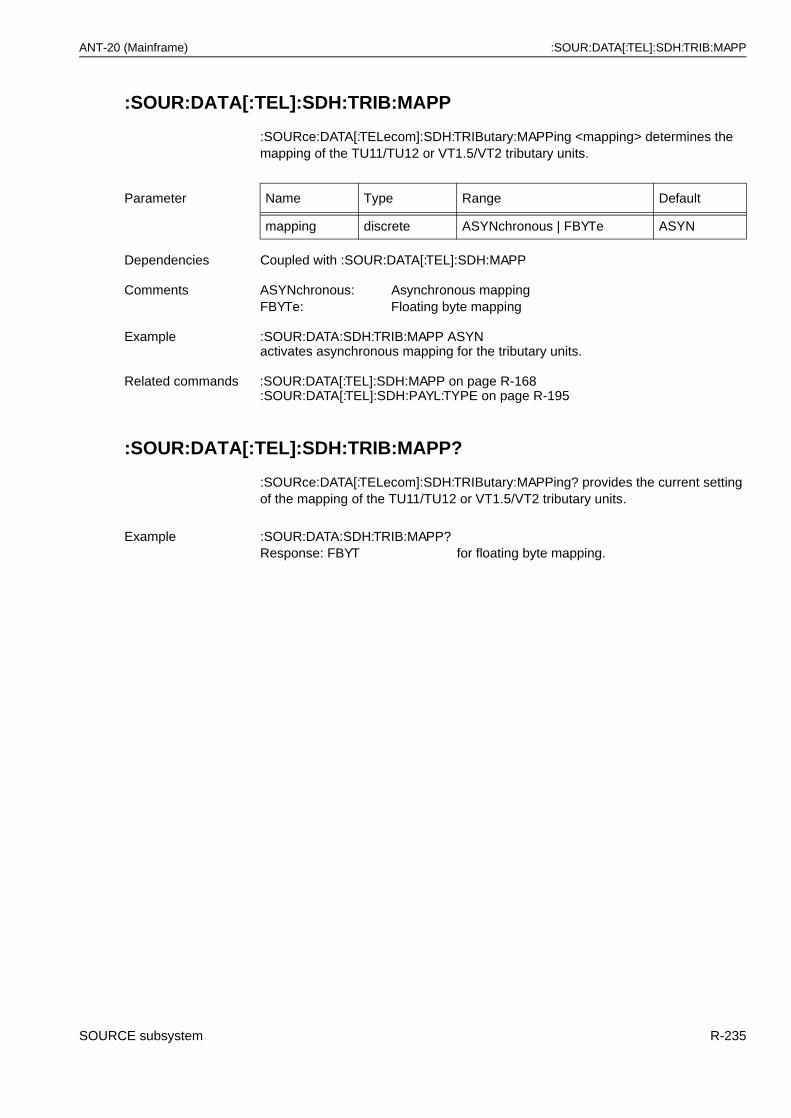
ANT-20 (Mainframe) :SOUR:DATA[:TEL]:SDH:TRIB:MAPP
:SOUR:DATA[:TEL]:SDH:TRIB:MAPP
:SOURce:DATA[:TELecom]:SDH:TRIButary:MAPPing <mapping> determines the mapping of the TU11/TU12 or VT1.5/VT2 tributary units.
:SOUR:DATA[:TEL]:SDH:TRIB:MAPP?
:SOURce:DATA[:TELecom]:SDH:TRIButary:MAPPing? provides the current setting of the mapping of the TU11/TU12 or VT1.5/VT2 tributary units.
Parameter Name Type Range Default
mapping discrete ASYNchronous | FBYTe ASYN
Dependencies Coupled with :SOUR:DATA[:TEL]:SDH:MAPP
Comments ASYNchronous: Asynchronous mappingFBYTe: Floating byte mapping
Example :SOUR:DATA:SDH:TRIB:MAPP ASYNactivates asynchronous mapping for the tributary units.
Related commands :SOUR:DATA[:TEL]:SDH:MAPP on page R-168:SOUR:DATA[:TEL]:SDH:PAYL:TYPE on page R-195
Example :SOUR:DATA:SDH:TRIB:MAPP?Response: FBYT for floating byte mapping.
SOURCE subsystem R-235
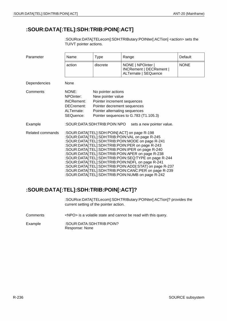
:SOUR:DATA[:TEL]:SDH:TRIB:POIN[:ACT] ANT-20 (Mainframe)
:SOUR:DATA[:TEL]:SDH:TRIB:POIN[:ACT]
:SOURce:DATA[:TELecom]:SDH:TRIButary:POINter[:ACTion] <action> sets the TU/VT pointer actions.
:SOUR:DATA[:TEL]:SDH:TRIB:POIN[:ACT]?
:SOURce:DATA[:TELecom]:SDH:TRIButary:POINter[:ACTion]? provides the current setting of the pointer action.
Parameter Name Type Range Default
action discrete NONE | NPOinter |INCRement | DECRement | ALTernate | SEQuence
NONE
Dependencies None
Comments NONE: No pointer actionsNPOinter: New pointer valueINCRement: Pointer increment sequencesDECrement: Pointer decrement sequencesALTernate: Pointer alternating sequencesSEQuence: Pointer sequences to G.783 (T1.105.3)
Example :SOUR:DATA:SDH:TRIB:POIN NPO sets a new pointer value.
Related commands :SOUR:DATA[:TEL]:SDH:POIN[:ACT] on page R-198:SOUR:DATA[:TEL]:SDH:TRIB:POIN:VAL on page R-245:SOUR:DATA[:TEL]:SDH:TRIB:POIN:MODE on page R-241:SOUR:DATA[:TEL]:SDH:TRIB:POIN:PER on page R-243:SOUR:DATA[:TEL]:SDH:TRIB:POIN:IPER on page R-240:SOUR:DATA[:TEL]:SDH:TRIB:POIN:APER on page R-238:SOUR:DATA[:TEL]:SDH:TRIB:POIN:SEQ:TYPE on page R-244:SOUR:DATA[:TEL]:SDH:TRIB:POIN:NDFL on page R-241:SOUR:DATA[:TEL]:SDH:TRIB:POIN:ADD[:STAT] on page R-237:SOUR:DATA[:TEL]:SDH:TRIB:POIN:CANC:PER on page R-239:SOUR:DATA[:TEL]:SDH:TRIB:POIN:NUMB on page R-242
Comments <NPO> is a volatile state and cannot be read with this query.
Example :SOUR:DATA:SDH:TRIB:POIN?Response: None
R-236 SOURCE subsystem
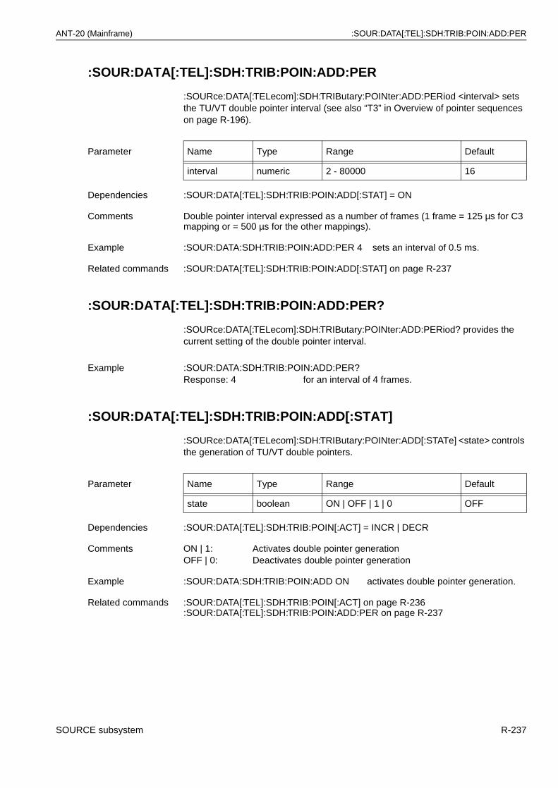
ANT-20 (Mainframe) :SOUR:DATA[:TEL]:SDH:TRIB:POIN:ADD:PER
:SOUR:DATA[:TEL]:SDH:TRIB:POIN:ADD:PER
:SOURce:DATA[:TELecom]:SDH:TRIButary:POINter:ADD:PERiod <interval> sets the TU/VT double pointer interval (see also “T3” in Overview of pointer sequences on page R-196).
:SOUR:DATA[:TEL]:SDH:TRIB:POIN:ADD:PER?
:SOURce:DATA[:TELecom]:SDH:TRIButary:POINter:ADD:PERiod? provides the current setting of the double pointer interval.
:SOUR:DATA[:TEL]:SDH:TRIB:POIN:ADD[:STAT]
:SOURce:DATA[:TELecom]:SDH:TRIButary:POINter:ADD[:STATe] <state> controls the generation of TU/VT double pointers.
Parameter Name Type Range Default
interval numeric 2 - 80000 16
Dependencies :SOUR:DATA[:TEL]:SDH:TRIB:POIN:ADD[:STAT] = ON
Comments Double pointer interval expressed as a number of frames (1 frame = 125 µs for C3 mapping or = 500 µs for the other mappings).
Example :SOUR:DATA:SDH:TRIB:POIN:ADD:PER 4 sets an interval of 0.5 ms.
Related commands :SOUR:DATA[:TEL]:SDH:TRIB:POIN:ADD[:STAT] on page R-237
Example :SOUR:DATA:SDH:TRIB:POIN:ADD:PER?Response: 4 for an interval of 4 frames.
Parameter Name Type Range Default
state boolean ON | OFF | 1 | 0 OFF
Dependencies :SOUR:DATA[:TEL]:SDH:TRIB:POIN[:ACT] = INCR | DECR
Comments ON | 1: Activates double pointer generationOFF | 0: Deactivates double pointer generation
Example :SOUR:DATA:SDH:TRIB:POIN:ADD ON activates double pointer generation.
Related commands :SOUR:DATA[:TEL]:SDH:TRIB:POIN[:ACT] on page R-236:SOUR:DATA[:TEL]:SDH:TRIB:POIN:ADD:PER on page R-237
SOURCE subsystem R-237

:SOUR:DATA[:TEL]:SDH:TRIB:POIN:ADD[:STAT]? ANT-20 (Mainframe)
:SOUR:DATA[:TEL]:SDH:TRIB:POIN:ADD[:STAT]?
:SOURce:DATA[:TELecom]:SDH:TRIButary:POINter:ADD[:STATe]? provides the current setting of TU/VT double pointer generation.
:SOUR:DATA[:TEL]:SDH:TRIB:POIN:APER
:SOURce:DATA[:TELecom]:SDH:TRIButary:POINter:APERiod <period> sets the TU/VT pointer adjustment period (see also “T2” in Overview of pointer sequences on page R-196).
:SOUR:DATA[:TEL]:SDH:TRIB:POIN:APER?
:SOURce:DATA[:TELecom]:SDH:TRIButary:POINter:APERiod? provides the current adjustment period.
Example :SOUR:DATA:SDH:TRIB:POIN:ADD?Response: 0 if double pointer generation is switched off.
Parameter Name Type Range Default
period numeric 2 - 80000 8000
Dependencies None
Comments <frames>: Pointer adjustment period expressed as a number of frames(1 frame = 125 µs for C3 mapping or = 500 µs for the othermappings).
Example :SOUR:DATA:SDH:TRIB:POIN:APER 10000sets the adjustment period to 10000 frames.
Related commands :SOUR:DATA[:TEL]:SDH:TRIB:POIN[:ACT] on page R-236:SOUR:DATA[:TEL]:SDH:TRIB:POIN:IPER on page R-240:SOUR:DATA[:TEL]:SDH:TRIB:POIN:PER on page R-243
Example :SOUR:DATA:SDH:TRIB:POIN:APER?Response: 10000
R-238 SOURCE subsystem
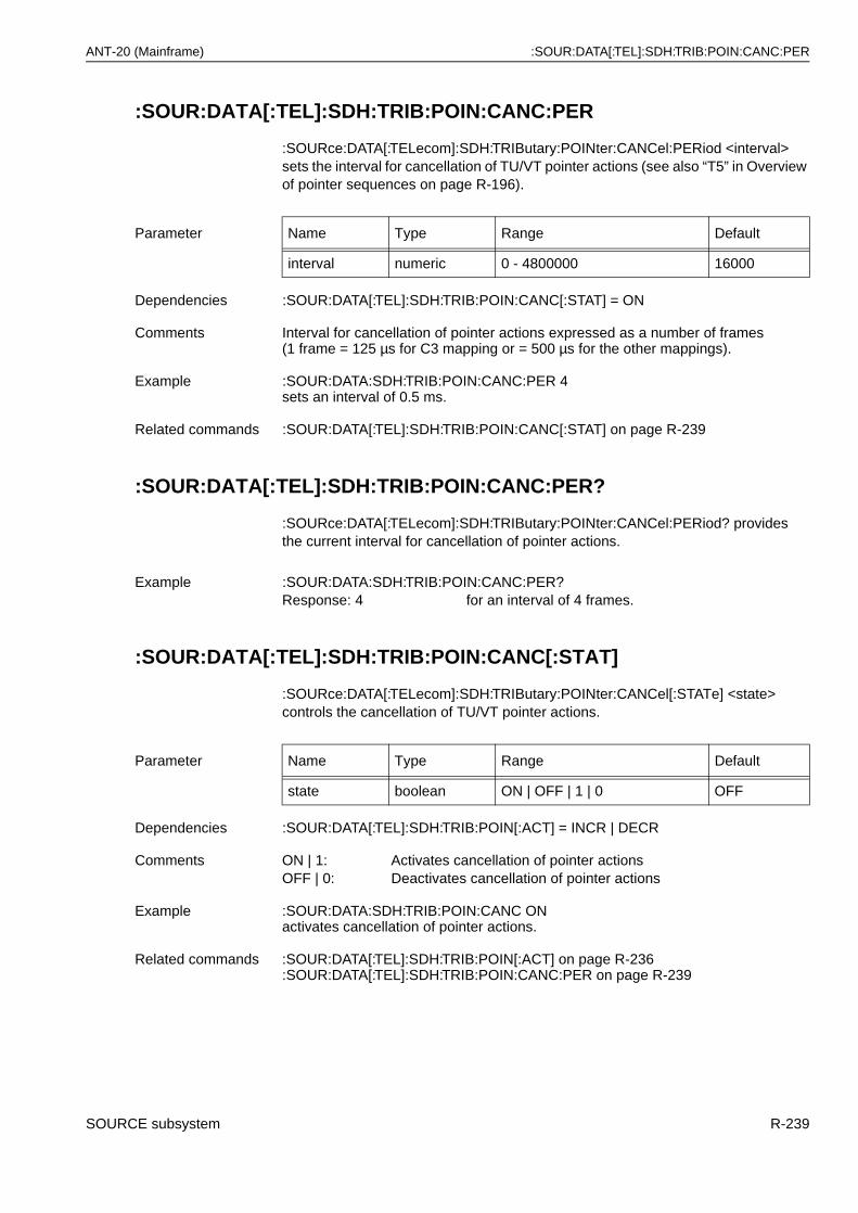
ANT-20 (Mainframe) :SOUR:DATA[:TEL]:SDH:TRIB:POIN:CANC:PER
:SOUR:DATA[:TEL]:SDH:TRIB:POIN:CANC:PER
:SOURce:DATA[:TELecom]:SDH:TRIButary:POINter:CANCel:PERiod <interval> sets the interval for cancellation of TU/VT pointer actions (see also “T5” in Overview of pointer sequences on page R-196).
:SOUR:DATA[:TEL]:SDH:TRIB:POIN:CANC:PER?
:SOURce:DATA[:TELecom]:SDH:TRIButary:POINter:CANCel:PERiod? provides the current interval for cancellation of pointer actions.
:SOUR:DATA[:TEL]:SDH:TRIB:POIN:CANC[:STAT]
:SOURce:DATA[:TELecom]:SDH:TRIButary:POINter:CANCel[:STATe] <state> controls the cancellation of TU/VT pointer actions.
Parameter Name Type Range Default
interval numeric 0 - 4800000 16000
Dependencies :SOUR:DATA[:TEL]:SDH:TRIB:POIN:CANC[:STAT] = ON
Comments Interval for cancellation of pointer actions expressed as a number of frames (1 frame = 125 µs for C3 mapping or = 500 µs for the other mappings).
Example :SOUR:DATA:SDH:TRIB:POIN:CANC:PER 4sets an interval of 0.5 ms.
Related commands :SOUR:DATA[:TEL]:SDH:TRIB:POIN:CANC[:STAT] on page R-239
Example :SOUR:DATA:SDH:TRIB:POIN:CANC:PER?Response: 4 for an interval of 4 frames.
Parameter Name Type Range Default
state boolean ON | OFF | 1 | 0 OFF
Dependencies :SOUR:DATA[:TEL]:SDH:TRIB:POIN[:ACT] = INCR | DECR
Comments ON | 1: Activates cancellation of pointer actionsOFF | 0: Deactivates cancellation of pointer actions
Example :SOUR:DATA:SDH:TRIB:POIN:CANC ONactivates cancellation of pointer actions.
Related commands :SOUR:DATA[:TEL]:SDH:TRIB:POIN[:ACT] on page R-236:SOUR:DATA[:TEL]:SDH:TRIB:POIN:CANC:PER on page R-239
SOURCE subsystem R-239
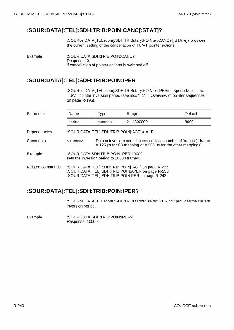
:SOUR:DATA[:TEL]:SDH:TRIB:POIN:CANC[:STAT]? ANT-20 (Mainframe)
:SOUR:DATA[:TEL]:SDH:TRIB:POIN:CANC[:STAT]?
:SOURce:DATA[:TELecom]:SDH:TRIButary:POINter:CANCel[:STATe]? provides the current setting of the cancellation of TU/VT pointer actions.
:SOUR:DATA[:TEL]:SDH:TRIB:POIN:IPER
:SOURce:DATA[:TELecom]:SDH:TRIButary:POINter:IPERiod <period> sets the TU/VT pointer inversion period (see also “T1” in Overview of pointer sequences on page R-196).
:SOUR:DATA[:TEL]:SDH:TRIB:POIN:IPER?
:SOURce:DATA[:TELecom]:SDH:TRIButary:POINter:IPERiod? provides the current inversion period.
Example :SOUR:DATA:SDH:TRIB:POIN:CANC?Response: 0if cancellation of pointer actions is switched off.
Parameter Name Type Range Default
period numeric 2 - 4800000 8000
Dependencies :SOUR:DATA[:TEL]:SDH:TRIB:POIN[:ACT] = ALT
Comments <frames>: Pointer inversion period expressed as a number of frames (1 frame = 125 µs for C3 mapping or = 500 µs for the other mappings).
Example :SOUR:DATA:SDH:TRIB:POIN:IPER 10000sets the inversion period to 10000 frames.
Related commands :SOUR:DATA[:TEL]:SDH:TRIB:POIN[:ACT] on page R-236:SOUR:DATA[:TEL]:SDH:TRIB:POIN:APER on page R-238:SOUR:DATA[:TEL]:SDH:TRIB:POIN:PER on page R-243
Example :SOUR:DATA:SDH:TRIB:POIN:IPER?Response: 10000
R-240 SOURCE subsystem
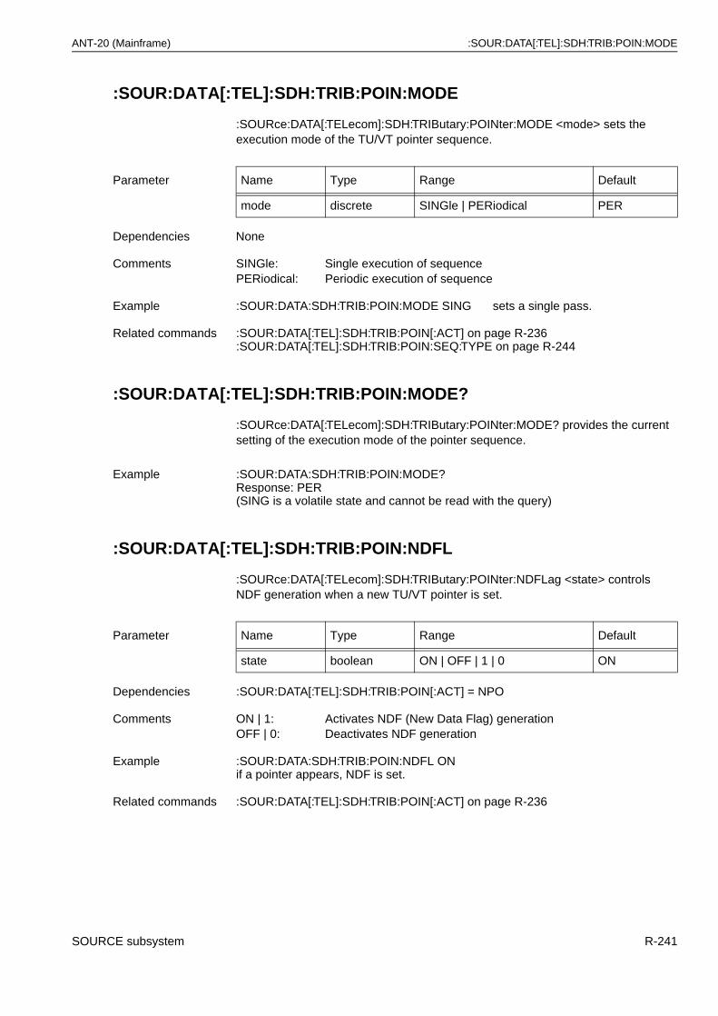
ANT-20 (Mainframe) :SOUR:DATA[:TEL]:SDH:TRIB:POIN:MODE
:SOUR:DATA[:TEL]:SDH:TRIB:POIN:MODE
:SOURce:DATA[:TELecom]:SDH:TRIButary:POINter:MODE <mode> sets the execution mode of the TU/VT pointer sequence.
:SOUR:DATA[:TEL]:SDH:TRIB:POIN:MODE?
:SOURce:DATA[:TELecom]:SDH:TRIButary:POINter:MODE? provides the current setting of the execution mode of the pointer sequence.
:SOUR:DATA[:TEL]:SDH:TRIB:POIN:NDFL
:SOURce:DATA[:TELecom]:SDH:TRIButary:POINter:NDFLag <state> controls NDF generation when a new TU/VT pointer is set.
Parameter Name Type Range Default
mode discrete SINGle | PERiodical PER
Dependencies None
Comments SINGle: Single execution of sequencePERiodical: Periodic execution of sequence
Example :SOUR:DATA:SDH:TRIB:POIN:MODE SING sets a single pass.
Related commands :SOUR:DATA[:TEL]:SDH:TRIB:POIN[:ACT] on page R-236:SOUR:DATA[:TEL]:SDH:TRIB:POIN:SEQ:TYPE on page R-244
Example :SOUR:DATA:SDH:TRIB:POIN:MODE?Response: PER(SING is a volatile state and cannot be read with the query)
Parameter Name Type Range Default
state boolean ON | OFF | 1 | 0 ON
Dependencies :SOUR:DATA[:TEL]:SDH:TRIB:POIN[:ACT] = NPO
Comments ON | 1: Activates NDF (New Data Flag) generationOFF | 0: Deactivates NDF generation
Example :SOUR:DATA:SDH:TRIB:POIN:NDFL ONif a pointer appears, NDF is set.
Related commands :SOUR:DATA[:TEL]:SDH:TRIB:POIN[:ACT] on page R-236
SOURCE subsystem R-241
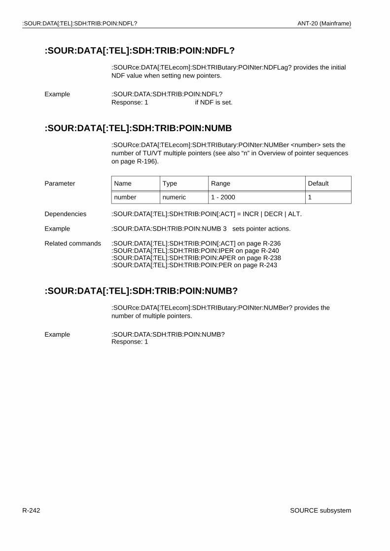
:SOUR:DATA[:TEL]:SDH:TRIB:POIN:NDFL? ANT-20 (Mainframe)
:SOUR:DATA[:TEL]:SDH:TRIB:POIN:NDFL?
:SOURce:DATA[:TELecom]:SDH:TRIButary:POINter:NDFLag? provides the initial NDF value when setting new pointers.
:SOUR:DATA[:TEL]:SDH:TRIB:POIN:NUMB
:SOURce:DATA[:TELecom]:SDH:TRIButary:POINter:NUMBer <number> sets the number of TU/VT multiple pointers (see also “n” in Overview of pointer sequences on page R-196).
:SOUR:DATA[:TEL]:SDH:TRIB:POIN:NUMB?
:SOURce:DATA[:TELecom]:SDH:TRIButary:POINter:NUMBer? provides the number of multiple pointers.
Example :SOUR:DATA:SDH:TRIB:POIN:NDFL?Response: 1 if NDF is set.
Parameter Name Type Range Default
number numeric 1 - 2000 1
Dependencies :SOUR:DATA[:TEL]:SDH:TRIB:POIN[:ACT] = INCR | DECR | ALT.
Example :SOUR:DATA:SDH:TRIB:POIN:NUMB 3 sets pointer actions.
Related commands :SOUR:DATA[:TEL]:SDH:TRIB:POIN[:ACT] on page R-236:SOUR:DATA[:TEL]:SDH:TRIB:POIN:IPER on page R-240:SOUR:DATA[:TEL]:SDH:TRIB:POIN:APER on page R-238:SOUR:DATA[:TEL]:SDH:TRIB:POIN:PER on page R-243
Example :SOUR:DATA:SDH:TRIB:POIN:NUMB?Response: 1
R-242 SOURCE subsystem
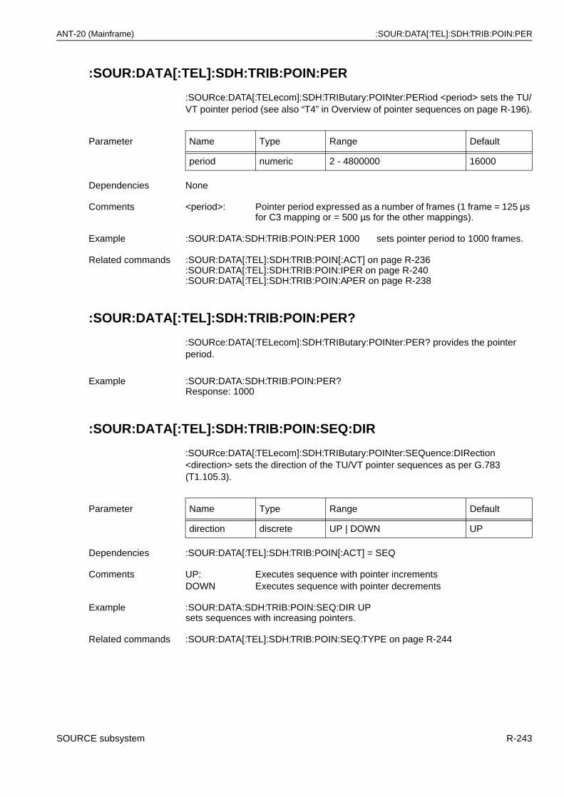
ANT-20 (Mainframe) :SOUR:DATA[:TEL]:SDH:TRIB:POIN:PER
:SOUR:DATA[:TEL]:SDH:TRIB:POIN:PER
:SOURce:DATA[:TELecom]:SDH:TRIButary:POINter:PERiod <period> sets the TU/VT pointer period (see also “T4” in Overview of pointer sequences on page R-196).
:SOUR:DATA[:TEL]:SDH:TRIB:POIN:PER?
:SOURce:DATA[:TELecom]:SDH:TRIButary:POINter:PER? provides the pointer period.
:SOUR:DATA[:TEL]:SDH:TRIB:POIN:SEQ:DIR
:SOURce:DATA[:TELecom]:SDH:TRIButary:POINter:SEQuence:DIRection <direction> sets the direction of the TU/VT pointer sequences as per G.783 (T1.105.3).
Parameter Name Type Range Default
period numeric 2 - 4800000 16000
Dependencies None
Comments <period>: Pointer period expressed as a number of frames (1 frame = 125 µs for C3 mapping or = 500 µs for the other mappings).
Example :SOUR:DATA:SDH:TRIB:POIN:PER 1000 sets pointer period to 1000 frames.
Related commands :SOUR:DATA[:TEL]:SDH:TRIB:POIN[:ACT] on page R-236:SOUR:DATA[:TEL]:SDH:TRIB:POIN:IPER on page R-240:SOUR:DATA[:TEL]:SDH:TRIB:POIN:APER on page R-238
Example :SOUR:DATA:SDH:TRIB:POIN:PER?Response: 1000
Parameter Name Type Range Default
direction discrete UP | DOWN UP
Dependencies :SOUR:DATA[:TEL]:SDH:TRIB:POIN[:ACT] = SEQ
Comments UP: Executes sequence with pointer incrementsDOWN Executes sequence with pointer decrements
Example :SOUR:DATA:SDH:TRIB:POIN:SEQ:DIR UPsets sequences with increasing pointers.
Related commands :SOUR:DATA[:TEL]:SDH:TRIB:POIN:SEQ:TYPE on page R-244
SOURCE subsystem R-243
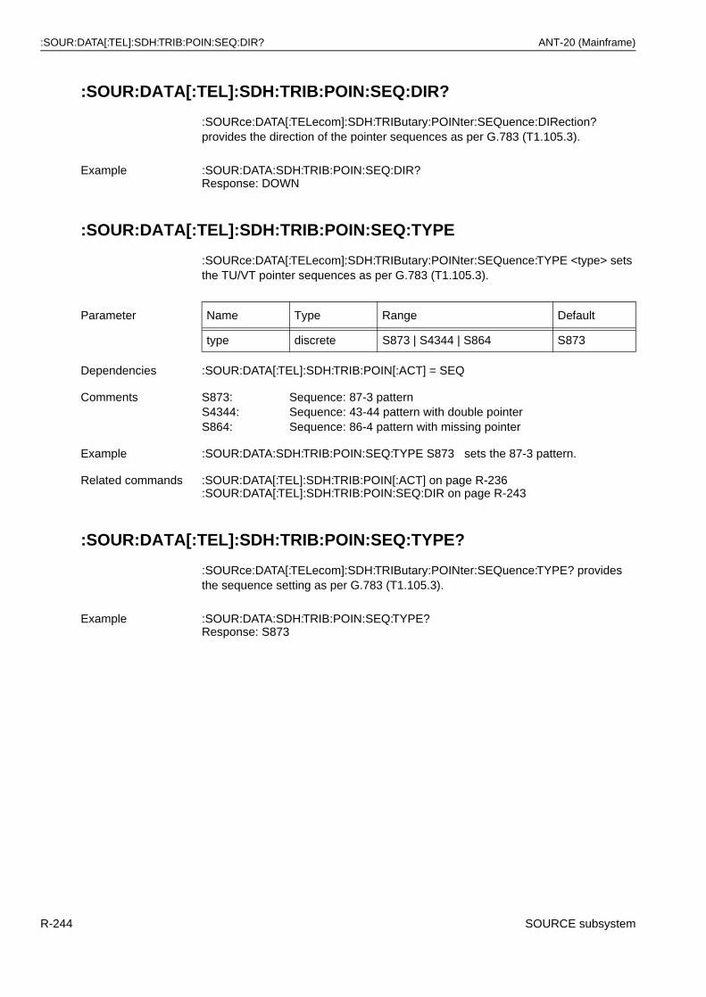
:SOUR:DATA[:TEL]:SDH:TRIB:POIN:SEQ:DIR? ANT-20 (Mainframe)
:SOUR:DATA[:TEL]:SDH:TRIB:POIN:SEQ:DIR?
:SOURce:DATA[:TELecom]:SDH:TRIButary:POINter:SEQuence:DIRection? provides the direction of the pointer sequences as per G.783 (T1.105.3).
:SOUR:DATA[:TEL]:SDH:TRIB:POIN:SEQ:TYPE
:SOURce:DATA[:TELecom]:SDH:TRIButary:POINter:SEQuence:TYPE <type> sets the TU/VT pointer sequences as per G.783 (T1.105.3).
:SOUR:DATA[:TEL]:SDH:TRIB:POIN:SEQ:TYPE?
:SOURce:DATA[:TELecom]:SDH:TRIButary:POINter:SEQuence:TYPE? provides the sequence setting as per G.783 (T1.105.3).
Example :SOUR:DATA:SDH:TRIB:POIN:SEQ:DIR?Response: DOWN
Parameter Name Type Range Default
type discrete S873 | S4344 | S864 S873
Dependencies :SOUR:DATA[:TEL]:SDH:TRIB:POIN[:ACT] = SEQ
Comments S873: Sequence: 87-3 patternS4344: Sequence: 43-44 pattern with double pointerS864: Sequence: 86-4 pattern with missing pointer
Example :SOUR:DATA:SDH:TRIB:POIN:SEQ:TYPE S873 sets the 87-3 pattern.
Related commands :SOUR:DATA[:TEL]:SDH:TRIB:POIN[:ACT] on page R-236:SOUR:DATA[:TEL]:SDH:TRIB:POIN:SEQ:DIR on page R-243
Example :SOUR:DATA:SDH:TRIB:POIN:SEQ:TYPE?Response: S873
R-244 SOURCE subsystem
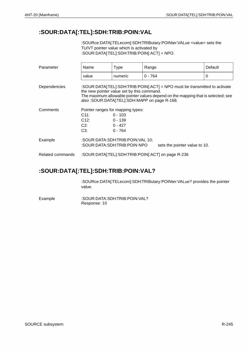
ANT-20 (Mainframe) :SOUR:DATA[:TEL]:SDH:TRIB:POIN:VAL
:SOUR:DATA[:TEL]:SDH:TRIB:POIN:VAL
:SOURce:DATA[:TELecom]:SDH:TRIButary:POINter:VALue <value> sets the TU/VT pointer value which is activated by :SOUR:DATA[:TEL]:SDH:TRIB:POIN[:ACT] = NPO.
:SOUR:DATA[:TEL]:SDH:TRIB:POIN:VAL?
:SOURce:DATA[:TELecom]:SDH:TRIButary:POINter:VALue? provides the pointer value.
Parameter Name Type Range Default
value numeric 0 - 764 0
Dependencies :SOUR:DATA[:TEL]:SDH:TRIB:POIN[:ACT] = NPO must be transmitted to activate the new pointer value set by this command.The maximum allowable pointer values depend on the mapping that is selected; see also :SOUR:DATA[:TEL]:SDH:MAPP on page R-168.
Comments Pointer ranges for mapping types:C11: 0 - 103C12: 0 - 139C2: 0 - 427C3: 0 - 764
Example :SOUR:DATA:SDH:TRIB:POIN:VAL 10;:SOUR:DATA:SDH:TRIB:POIN NPO sets the pointer value to 10.
Related commands :SOUR:DATA[:TEL]:SDH:TRIB:POIN[:ACT] on page R-236
Example :SOUR:DATA:SDH:TRIB:POIN:VAL?Response: 10
SOURCE subsystem R-245
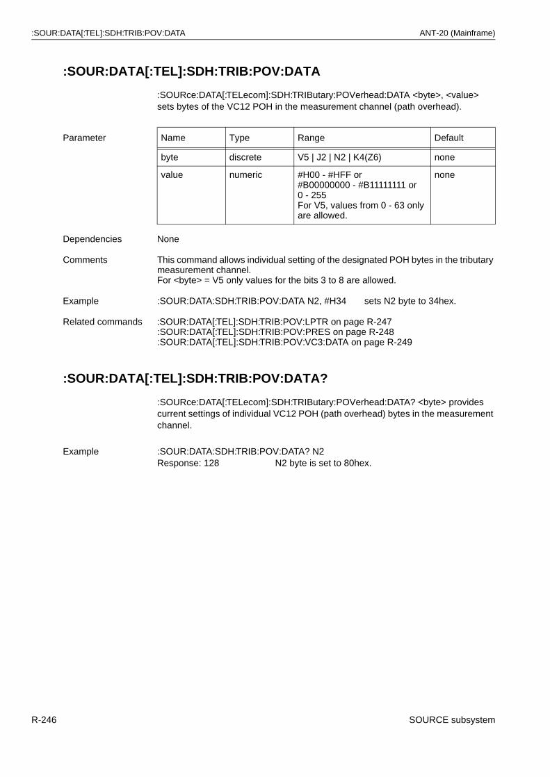
:SOUR:DATA[:TEL]:SDH:TRIB:POV:DATA ANT-20 (Mainframe)
:SOUR:DATA[:TEL]:SDH:TRIB:POV:DATA
:SOURce:DATA[:TELecom]:SDH:TRIButary:POVerhead:DATA <byte>, <value> sets bytes of the VC12 POH in the measurement channel (path overhead).
:SOUR:DATA[:TEL]:SDH:TRIB:POV:DATA?
:SOURce:DATA[:TELecom]:SDH:TRIButary:POVerhead:DATA? <byte> provides current settings of individual VC12 POH (path overhead) bytes in the measurement channel.
Parameter Name Type Range Default
byte discrete V5 | J2 | N2 | K4(Z6) none
value numeric #H00 - #HFF or#B00000000 - #B11111111 or 0 - 255For V5, values from 0 - 63 only are allowed.
none
Dependencies None
Comments This command allows individual setting of the designated POH bytes in the tributary measurement channel.For <byte> = V5 only values for the bits 3 to 8 are allowed.
Example :SOUR:DATA:SDH:TRIB:POV:DATA N2, #H34 sets N2 byte to 34hex.
Related commands :SOUR:DATA[:TEL]:SDH:TRIB:POV:LPTR on page R-247:SOUR:DATA[:TEL]:SDH:TRIB:POV:PRES on page R-248:SOUR:DATA[:TEL]:SDH:TRIB:POV:VC3:DATA on page R-249
Example :SOUR:DATA:SDH:TRIB:POV:DATA? N2Response: 128 N2 byte is set to 80hex.
R-246 SOURCE subsystem
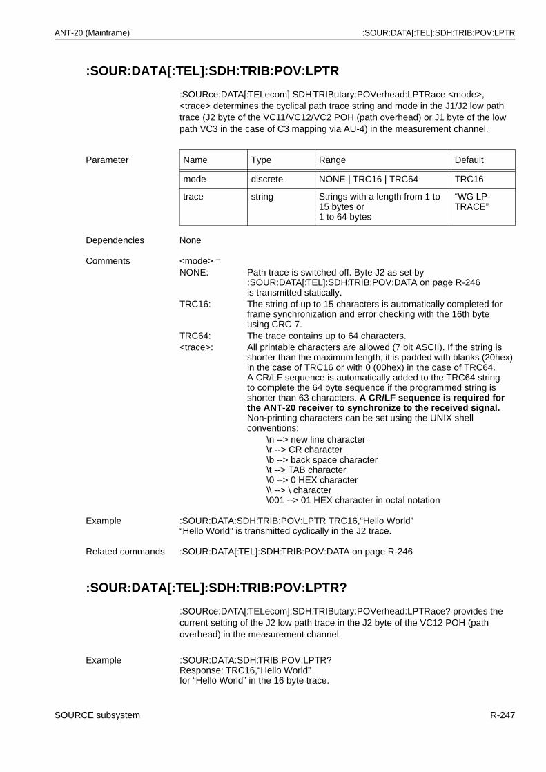
ANT-20 (Mainframe) :SOUR:DATA[:TEL]:SDH:TRIB:POV:LPTR
:SOUR:DATA[:TEL]:SDH:TRIB:POV:LPTR
:SOURce:DATA[:TELecom]:SDH:TRIButary:POVerhead:LPTRace <mode>, <trace> determines the cyclical path trace string and mode in the J1/J2 low path trace (J2 byte of the VC11/VC12/VC2 POH (path overhead) or J1 byte of the low path VC3 in the case of C3 mapping via AU-4) in the measurement channel.
:SOUR:DATA[:TEL]:SDH:TRIB:POV:LPTR?
:SOURce:DATA[:TELecom]:SDH:TRIButary:POVerhead:LPTRace? provides the current setting of the J2 low path trace in the J2 byte of the VC12 POH (path overhead) in the measurement channel.
Parameter Name Type Range Default
mode discrete NONE | TRC16 | TRC64 TRC16
trace string Strings with a length from 1 to 15 bytes or1 to 64 bytes
“WG LP-TRACE”
Dependencies None
Comments <mode> =NONE: Path trace is switched off. Byte J2 as set by
:SOUR:DATA[:TEL]:SDH:TRIB:POV:DATA on page R-246is transmitted statically.
TRC16: The string of up to 15 characters is automatically completed forframe synchronization and error checking with the 16th byteusing CRC-7.
TRC64: The trace contains up to 64 characters.<trace>: All printable characters are allowed (7 bit ASCII). If the string is
shorter than the maximum length, it is padded with blanks (20hex) in the case of TRC16 or with 0 (00hex) in the case of TRC64.A CR/LF sequence is automatically added to the TRC64 string to complete the 64 byte sequence if the programmed string isshorter than 63 characters. A CR/LF sequence is required for the ANT-20 receiver to synchronize to the received signal.Non-printing characters can be set using the UNIX shell conventions:
\n --> new line character\r --> CR character\b --> back space character\t --> TAB character\0 --> 0 HEX character\\ --> \ character\001 --> 01 HEX character in octal notation
Example :SOUR:DATA:SDH:TRIB:POV:LPTR TRC16,“Hello World”“Hello World” is transmitted cyclically in the J2 trace.
Related commands :SOUR:DATA[:TEL]:SDH:TRIB:POV:DATA on page R-246
Example :SOUR:DATA:SDH:TRIB:POV:LPTR?Response: TRC16,“Hello World”for “Hello World” in the 16 byte trace.
SOURCE subsystem R-247
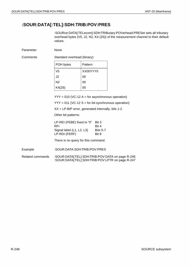
:SOUR:DATA[:TEL]:SDH:TRIB:POV:PRES ANT-20 (Mainframe)
:SOUR:DATA[:TEL]:SDH:TRIB:POV:PRES
:SOURce:DATA[:TELecom]:SDH:TRIButary:POVerhead:PRESet sets all tributary overhead bytes (V5, J2, N2, K4 (Z6)) of the measurement channel to their default values.
YYY = 010 (VC-12 A = for asynchronous operation)
YYY = 011 (VC-12 S = for bit-synchronous operation)
XX = LP-BIP error, generated internally, bits 1-2
Other bit patterns:
There is no query for this command.
Parameter None
Comments Standard overhead (binary):
POH bytes Pattern
V5
J2
N2
K4(Z6)
XX00YYY0
00
00
00
LP-REI (FEBE) fixed to “0” Bit 3RFI Bit 4Signal label (L1, L2, L3) Bits 5-7LP-RDI (FERF) Bit 8
Example :SOUR:DATA:SDH:TRIB:POV:PRES
Related commands :SOUR:DATA[:TEL]:SDH:TRIB:POV:DATA on page R-246:SOUR:DATA[:TEL]:SDH:TRIB:POV:LPTR on page R-247
R-248 SOURCE subsystem
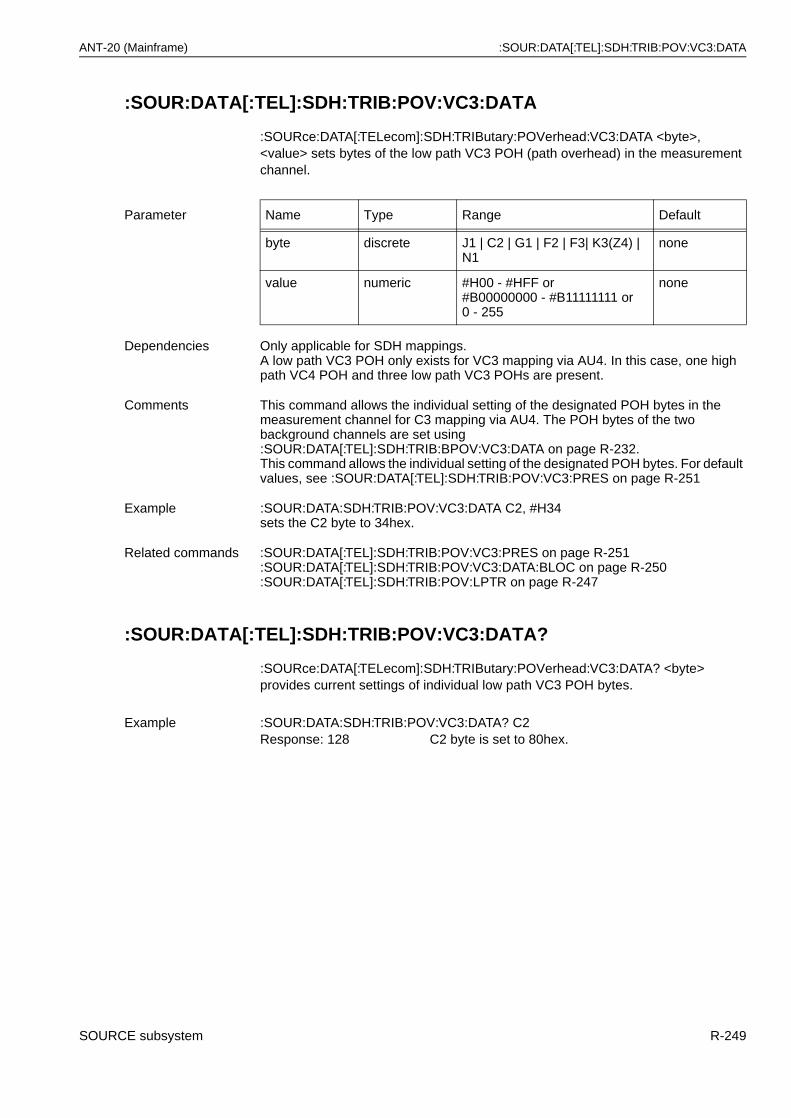
ANT-20 (Mainframe) :SOUR:DATA[:TEL]:SDH:TRIB:POV:VC3:DATA
:SOUR:DATA[:TEL]:SDH:TRIB:POV:VC3:DATA
:SOURce:DATA[:TELecom]:SDH:TRIButary:POVerhead:VC3:DATA <byte>, <value> sets bytes of the low path VC3 POH (path overhead) in the measurement channel.
:SOUR:DATA[:TEL]:SDH:TRIB:POV:VC3:DATA?
:SOURce:DATA[:TELecom]:SDH:TRIButary:POVerhead:VC3:DATA? <byte> provides current settings of individual low path VC3 POH bytes.
Parameter Name Type Range Default
byte discrete J1 | C2 | G1 | F2 | F3| K3(Z4) | N1
none
value numeric #H00 - #HFF or#B00000000 - #B11111111 or 0 - 255
none
Dependencies Only applicable for SDH mappings.A low path VC3 POH only exists for VC3 mapping via AU4. In this case, one high path VC4 POH and three low path VC3 POHs are present.
Comments This command allows the individual setting of the designated POH bytes in the measurement channel for C3 mapping via AU4. The POH bytes of the two background channels are set using :SOUR:DATA[:TEL]:SDH:TRIB:BPOV:VC3:DATA on page R-232.This command allows the individual setting of the designated POH bytes. For default values, see :SOUR:DATA[:TEL]:SDH:TRIB:POV:VC3:PRES on page R-251
Example :SOUR:DATA:SDH:TRIB:POV:VC3:DATA C2, #H34sets the C2 byte to 34hex.
Related commands :SOUR:DATA[:TEL]:SDH:TRIB:POV:VC3:PRES on page R-251:SOUR:DATA[:TEL]:SDH:TRIB:POV:VC3:DATA:BLOC on page R-250:SOUR:DATA[:TEL]:SDH:TRIB:POV:LPTR on page R-247
Example :SOUR:DATA:SDH:TRIB:POV:VC3:DATA? C2Response: 128 C2 byte is set to 80hex.
SOURCE subsystem R-249
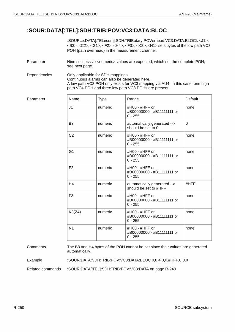
:SOUR:DATA[:TEL]:SDH:TRIB:POV:VC3:DATA:BLOC ANT-20 (Mainframe)
:SOUR:DATA[:TEL]:SDH:TRIB:POV:VC3:DATA:BLOC
:SOURce:DATA[:TELecom]:SDH:TRIButary:POVerhead:VC3:DATA:BLOCk <J1>, <B3>, <C2>, <G1>, <F2>, <H4>, <F3>, <K3>, <N1> sets bytes of the low path VC3 POH (path overhead) in the measurement channel.
Parameter Nine successive <numeric> values are expected, which set the complete POH;see next page.
Dependencies Only applicable for SDH mappings.Continuous alarms can also be generated here.A low path VC3 POH only exists for VC3 mapping via AU4. In this case, one high path VC4 POH and three low path VC3 POHs are present.
Parameter Name Type Range Default
J1 numeric #H00 - #HFF or#B00000000 - #B11111111 or 0 - 255
none
B3 numeric automatically generated --> should be set to 0
0
C2 numeric #H00 - #HFF or#B00000000 - #B11111111 or 0 - 255
none
G1 numeric #H00 - #HFF or#B00000000 - #B11111111 or 0 - 255
none
F2 numeric #H00 - #HFF or#B00000000 - #B11111111 or 0 - 255
none
H4 numeric automatically generated --> should be set to #HFF
#HFF
F3 numeric #H00 - #HFF or#B00000000 - #B11111111 or 0 - 255
none
K3(Z4) numeric #H00 - #HFF or#B00000000 - #B11111111 or 0 - 255
none
N1 numeric #H00 - #HFF or#B00000000 - #B11111111 or 0 - 255
none
Comments The B3 and H4 bytes of the POH cannot be set since their values are generated automatically.
Example :SOUR:DATA:SDH:TRIB:POV:VC3:DATA:BLOC 0,0,4,0,0,#HFF,0,0,0
Related commands :SOUR:DATA[:TEL]:SDH:TRIB:POV:VC3:DATA on page R-249
R-250 SOURCE subsystem
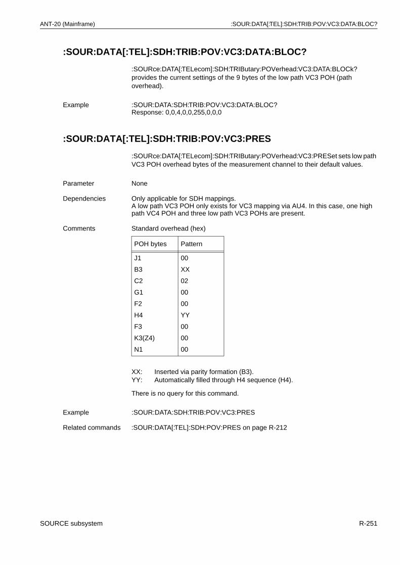
ANT-20 (Mainframe) :SOUR:DATA[:TEL]:SDH:TRIB:POV:VC3:DATA:BLOC?
:SOUR:DATA[:TEL]:SDH:TRIB:POV:VC3:DATA:BLOC?
:SOURce:DATA[:TELecom]:SDH:TRIButary:POVerhead:VC3:DATA:BLOCk? provides the current settings of the 9 bytes of the low path VC3 POH (path overhead).
:SOUR:DATA[:TEL]:SDH:TRIB:POV:VC3:PRES
:SOURce:DATA[:TELecom]:SDH:TRIButary:POVerhead:VC3:PRESet sets low path VC3 POH overhead bytes of the measurement channel to their default values.
There is no query for this command.
Example :SOUR:DATA:SDH:TRIB:POV:VC3:DATA:BLOC?Response: 0,0,4,0,0,255,0,0,0
Parameter None
Dependencies Only applicable for SDH mappings.A low path VC3 POH only exists for VC3 mapping via AU4. In this case, one high path VC4 POH and three low path VC3 POHs are present.
Comments Standard overhead (hex)
POH bytes Pattern
J1
B3
C2
G1
F2
H4
F3
K3(Z4)
N1
00
XX
02
00
00
YY
00
00
00
XX: Inserted via parity formation (B3).YY: Automatically filled through H4 sequence (H4).
Example :SOUR:DATA:SDH:TRIB:POV:VC3:PRES
Related commands :SOUR:DATA[:TEL]:SDH:POV:PRES on page R-212
SOURCE subsystem R-251
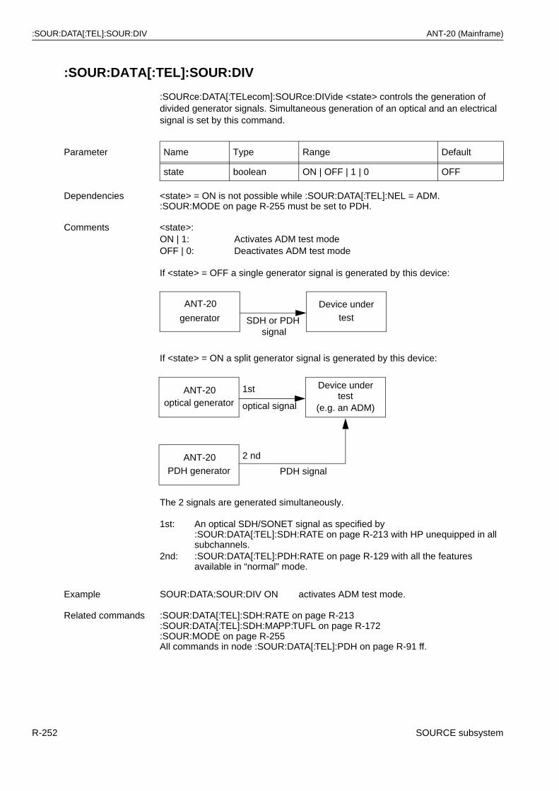
:SOUR:DATA[:TEL]:SOUR:DIV ANT-20 (Mainframe)
:SOUR:DATA[:TEL]:SOUR:DIV
:SOURce:DATA[:TELecom]:SOURce:DIVide <state> controls the generation of divided generator signals. Simultaneous generation of an optical and an electrical signal is set by this command.
If <state> = ON a split generator signal is generated by this device:
The 2 signals are generated simultaneously.
Parameter Name Type Range Default
state boolean ON | OFF | 1 | 0 OFF
Dependencies <state> = ON is not possible while :SOUR:DATA[:TEL]:NEL = ADM.:SOUR:MODE on page R-255 must be set to PDH.
Comments <state>:ON | 1: Activates ADM test modeOFF | 0: Deactivates ADM test mode
If <state> = OFF a single generator signal is generated by this device:
1st: An optical SDH/SONET signal as specified by:SOUR:DATA[:TEL]:SDH:RATE on page R-213 with HP unequipped in all subchannels.
2nd: :SOUR:DATA[:TEL]:PDH:RATE on page R-129 with all the features available in “normal” mode.
Example SOUR:DATA:SOUR:DIV ON activates ADM test mode.
Related commands :SOUR:DATA[:TEL]:SDH:RATE on page R-213:SOUR:DATA[:TEL]:SDH:MAPP:TUFL on page R-172:SOUR:MODE on page R-255All commands in node :SOUR:DATA[:TEL]:PDH on page R-91 ff.
Device undertest
ANT-20
generator SDH or PDHsignal
Device undertest
ANT-20optical generator
PDH signal
optical signal (e.g. an ADM)
ANT-20PDH generator
1st
2 nd
R-252 SOURCE subsystem
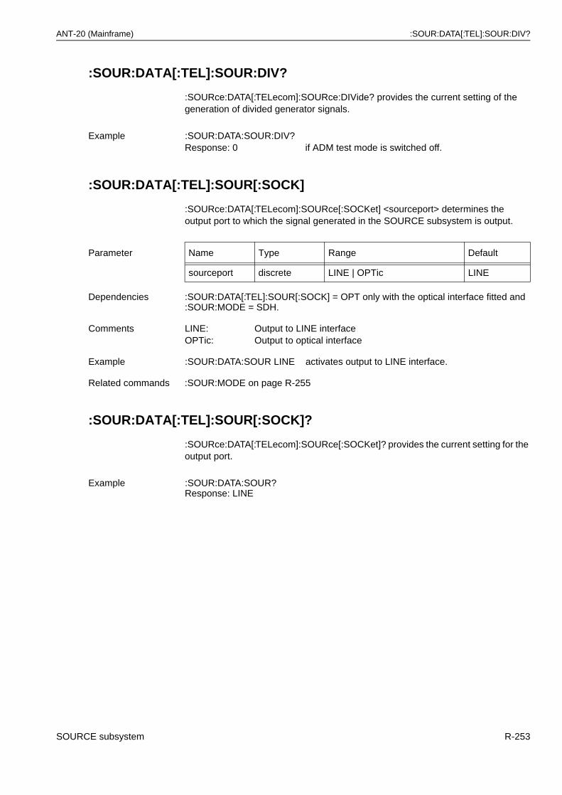
ANT-20 (Mainframe) :SOUR:DATA[:TEL]:SOUR:DIV?
:SOUR:DATA[:TEL]:SOUR:DIV?
:SOURce:DATA[:TELecom]:SOURce:DIVide? provides the current setting of the generation of divided generator signals.
:SOUR:DATA[:TEL]:SOUR[:SOCK]
:SOURce:DATA[:TELecom]:SOURce[:SOCKet] <sourceport> determines the output port to which the signal generated in the SOURCE subsystem is output.
:SOUR:DATA[:TEL]:SOUR[:SOCK]?
:SOURce:DATA[:TELecom]:SOURce[:SOCKet]? provides the current setting for the output port.
Example :SOUR:DATA:SOUR:DIV?Response: 0 if ADM test mode is switched off.
Parameter Name Type Range Default
sourceport discrete LINE | OPTic LINE
Dependencies :SOUR:DATA[:TEL]:SOUR[:SOCK] = OPT only with the optical interface fitted and :SOUR:MODE = SDH.
Comments LINE: Output to LINE interfaceOPTic: Output to optical interface
Example :SOUR:DATA:SOUR LINE activates output to LINE interface.
Related commands :SOUR:MODE on page R-255
Example :SOUR:DATA:SOUR?Response: LINE
SOURCE subsystem R-253
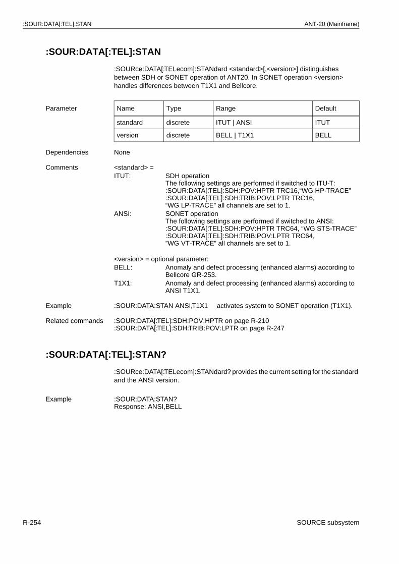
:SOUR:DATA[:TEL]:STAN ANT-20 (Mainframe)
:SOUR:DATA[:TEL]:STAN
:SOURce:DATA[:TELecom]:STANdard <standard>[,<version>] distinguishes between SDH or SONET operation of ANT20. In SONET operation <version> handles differences between T1X1 and Bellcore.
:SOUR:DATA[:TEL]:STAN?
:SOURce:DATA[:TELecom]:STANdard? provides the current setting for the standard and the ANSI version.
Parameter Name Type Range Default
standard discrete ITUT | ANSI ITUT
version discrete BELL | T1X1 BELL
Dependencies None
Comments <standard> =ITUT: SDH operation
The following settings are performed if switched to ITU-T: :SOUR:DATA[:TEL]:SDH:POV:HPTR TRC16,“WG HP-TRACE”:SOUR:DATA[:TEL]:SDH:TRIB:POV:LPTR TRC16,“WG LP-TRACE” all channels are set to 1.
ANSI: SONET operationThe following settings are performed if switched to ANSI: :SOUR:DATA[:TEL]:SDH:POV:HPTR TRC64, “WG STS-TRACE” :SOUR:DATA[:TEL]:SDH:TRIB:POV:LPTR TRC64,”WG VT-TRACE” all channels are set to 1.
<version> = optional parameter:BELL: Anomaly and defect processing (enhanced alarms) according to
Bellcore GR-253.T1X1: Anomaly and defect processing (enhanced alarms) according to
ANSI T1X1.
Example :SOUR:DATA:STAN ANSI,T1X1 activates system to SONET operation (T1X1).
Related commands :SOUR:DATA[:TEL]:SDH:POV:HPTR on page R-210:SOUR:DATA[:TEL]:SDH:TRIB:POV:LPTR on page R-247
Example :SOUR:DATA:STAN?Response: ANSI,BELL
R-254 SOURCE subsystem
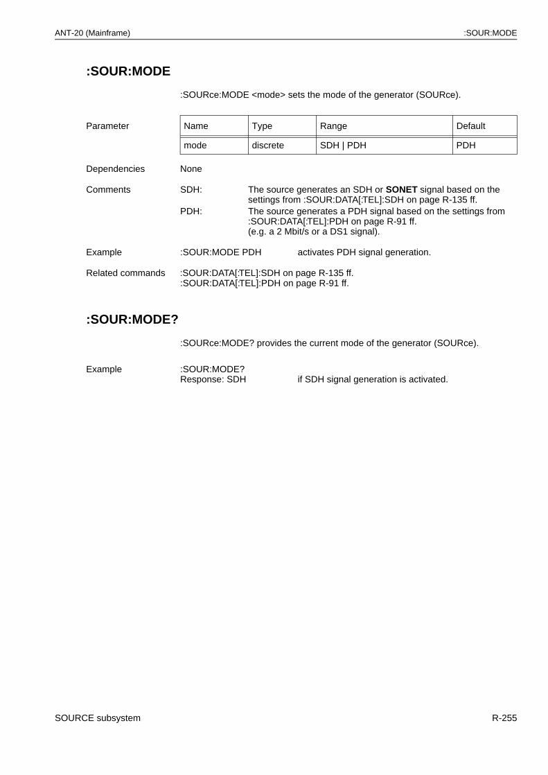
ANT-20 (Mainframe) :SOUR:MODE
:SOUR:MODE
:SOURce:MODE <mode> sets the mode of the generator (SOURce).
:SOUR:MODE?
:SOURce:MODE? provides the current mode of the generator (SOURce).
Parameter Name Type Range Default
mode discrete SDH | PDH PDH
Dependencies None
Comments SDH: The source generates an SDH or SONET signal based on the settings from :SOUR:DATA[:TEL]:SDH on page R-135 ff.
PDH: The source generates a PDH signal based on the settings from :SOUR:DATA[:TEL]:PDH on page R-91 ff.(e.g. a 2 Mbit/s or a DS1 signal).
Example :SOUR:MODE PDH activates PDH signal generation.
Related commands :SOUR:DATA[:TEL]:SDH on page R-135 ff.:SOUR:DATA[:TEL]:PDH on page R-91 ff.
Example :SOUR:MODE?Response: SDH if SDH signal generation is activated.
SOURCE subsystem R-255
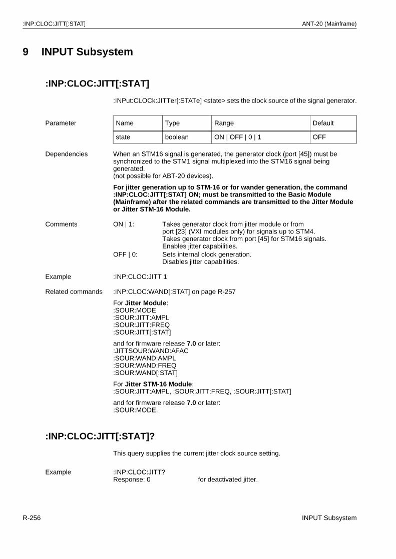
:INP:CLOC:JITT[:STAT] ANT-20 (Mainframe)
9 INPUT Subsystem
:INP:CLOC:JITT[:STAT]
:INPut:CLOCk:JITTer[:STATe] <state> sets the clock source of the signal generator.
:INP:CLOC:JITT[:STAT]?
This query supplies the current jitter clock source setting.
Parameter Name Type Range Default
state boolean ON | OFF | 0 | 1 OFF
Dependencies When an STM16 signal is generated, the generator clock (port [45]) must be synchronized to the STM1 signal multiplexed into the STM16 signal being generated.(not possible for ABT-20 devices).
For jitter generation up to STM-16 or for wander generation, the command :INP:CLOC:JITT[:STAT] ON; must be transmitted to the Basic Module (Mainframe) after the related commands are transmitted to the Jitter Module or Jitter STM-16 Module.
Comments ON | 1: Takes generator clock from jitter module or from port [23] (VXI modules only) for signals up to STM4.Takes generator clock from port [45] for STM16 signals.Enables jitter capabilities.
OFF | 0: Sets internal clock generation.Disables jitter capabilities.
Example :INP:CLOC:JITT 1
Related commands :INP:CLOC:WAND[:STAT] on page R-257
For Jitter Module::SOUR:MODE:SOUR:JITT:AMPL:SOUR:JITT:FREQ:SOUR:JITT[:STAT]
and for firmware release 7.0 or later::JITTSOUR:WAND:AFAC:SOUR:WAND:AMPL:SOUR:WAND:FREQ:SOUR:WAND[:STAT]
For Jitter STM-16 Module: :SOUR:JITT:AMPL, :SOUR:JITT:FREQ, :SOUR:JITT[:STAT]
and for firmware release 7.0 or later::SOUR:MODE.
Example :INP:CLOC:JITT?Response: 0 for deactivated jitter.
R-256 INPUT Subsystem
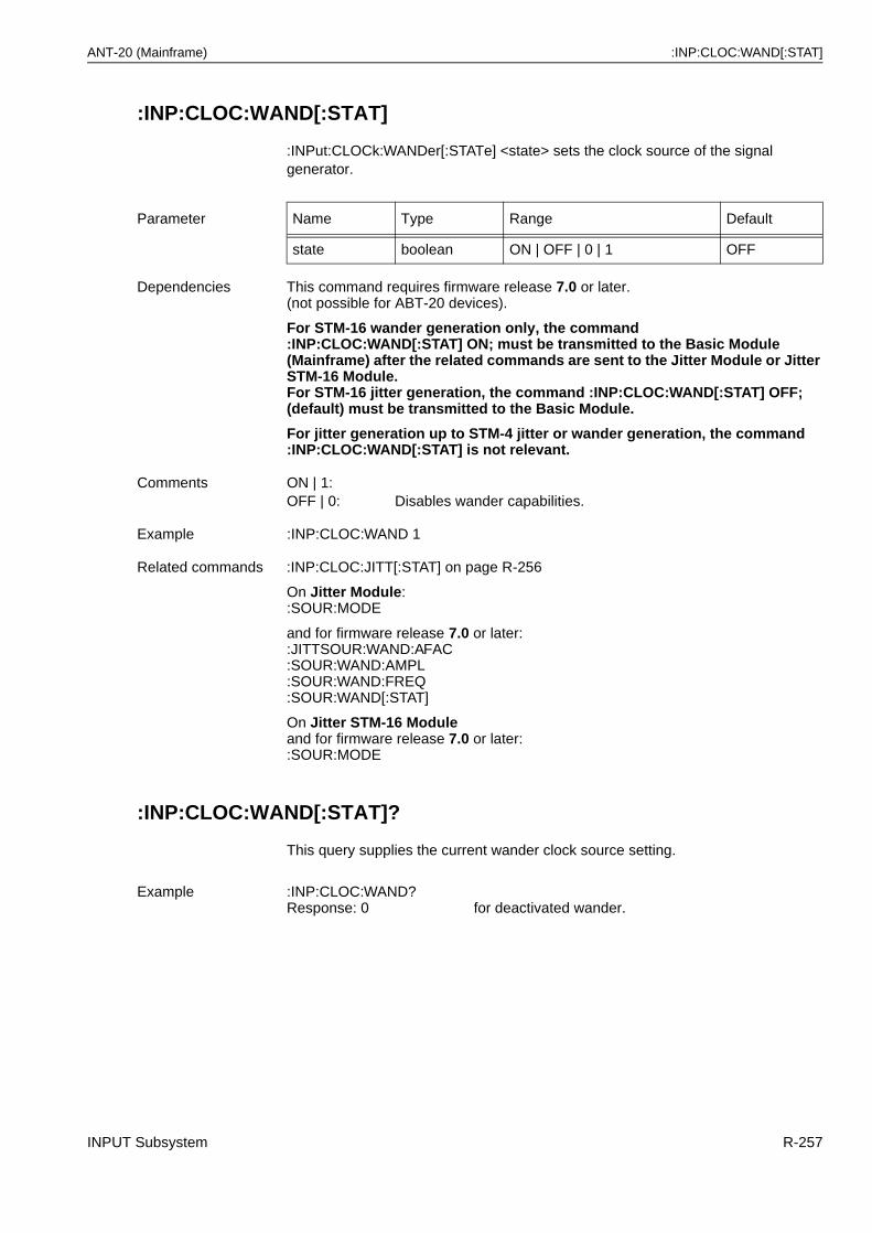
ANT-20 (Mainframe) :INP:CLOC:WAND[:STAT]
:INP:CLOC:WAND[:STAT]
:INPut:CLOCk:WANDer[:STATe] <state> sets the clock source of the signal generator.
:INP:CLOC:WAND[:STAT]?
This query supplies the current wander clock source setting.
Parameter Name Type Range Default
state boolean ON | OFF | 0 | 1 OFF
Dependencies This command requires firmware release 7.0 or later.(not possible for ABT-20 devices).
For STM-16 wander generation only, the command :INP:CLOC:WAND[:STAT] ON; must be transmitted to the Basic Module (Mainframe) after the related commands are sent to the Jitter Module or Jitter STM-16 Module.For STM-16 jitter generation, the command :INP:CLOC:WAND[:STAT] OFF; (default) must be transmitted to the Basic Module.
For jitter generation up to STM-4 jitter or wander generation, the command:INP:CLOC:WAND[:STAT] is not relevant.
Comments ON | 1:OFF | 0: Disables wander capabilities.
Example :INP:CLOC:WAND 1
Related commands :INP:CLOC:JITT[:STAT] on page R-256
On Jitter Module::SOUR:MODE
and for firmware release 7.0 or later: :JITTSOUR:WAND:AFAC:SOUR:WAND:AMPL:SOUR:WAND:FREQ:SOUR:WAND[:STAT]
On Jitter STM-16 Module and for firmware release 7.0 or later::SOUR:MODE
Example :INP:CLOC:WAND?Response: 0 for deactivated wander.
INPUT Subsystem R-257
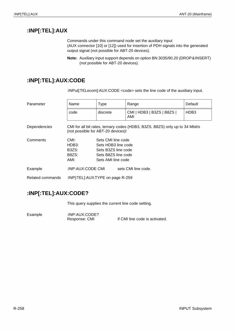
:INP[:TEL]:AUX ANT-20 (Mainframe)
:INP[:TEL]:AUX
Commands under this command node set the auxiliary input(AUX connector [10] or [12]) used for insertion of PDH signals into the generated output signal (not possible for ABT-20 devices).
Note: Auxiliary input support depends on option BN 3035/90.20 (DROP&INSERT) (not possible for ABT-20 devices).
:INP[:TEL]:AUX:CODE
:INPut[:TELecom]:AUX:CODE <code> sets the line code of the auxiliary input.
:INP[:TEL]:AUX:CODE?
This query supplies the current line code setting.
Parameter Name Type Range Default
code discrete CMI | HDB3 | B3ZS | B8ZS | AMI
HDB3
Dependencies CMI for all bit rates, ternary codes (HDB3, B3ZS, B8ZS) only up to 34 Mbit/s (not possible for ABT-20 devices)!
Comments CMI: Sets CMI line codeHDB3: Sets HDB3 line codeB3ZS: Sets B3ZS line codeB8ZS: Sets B8ZS line codeAMI: Sets AMI line code
Example :INP:AUX:CODE CMI sets CMI line code.
Related commands :INP[:TEL]:AUX:TYPE on page R-259
Example :INP:AUX:CODE?Response: CMI if CMI line code is activated.
R-258 INPUT Subsystem
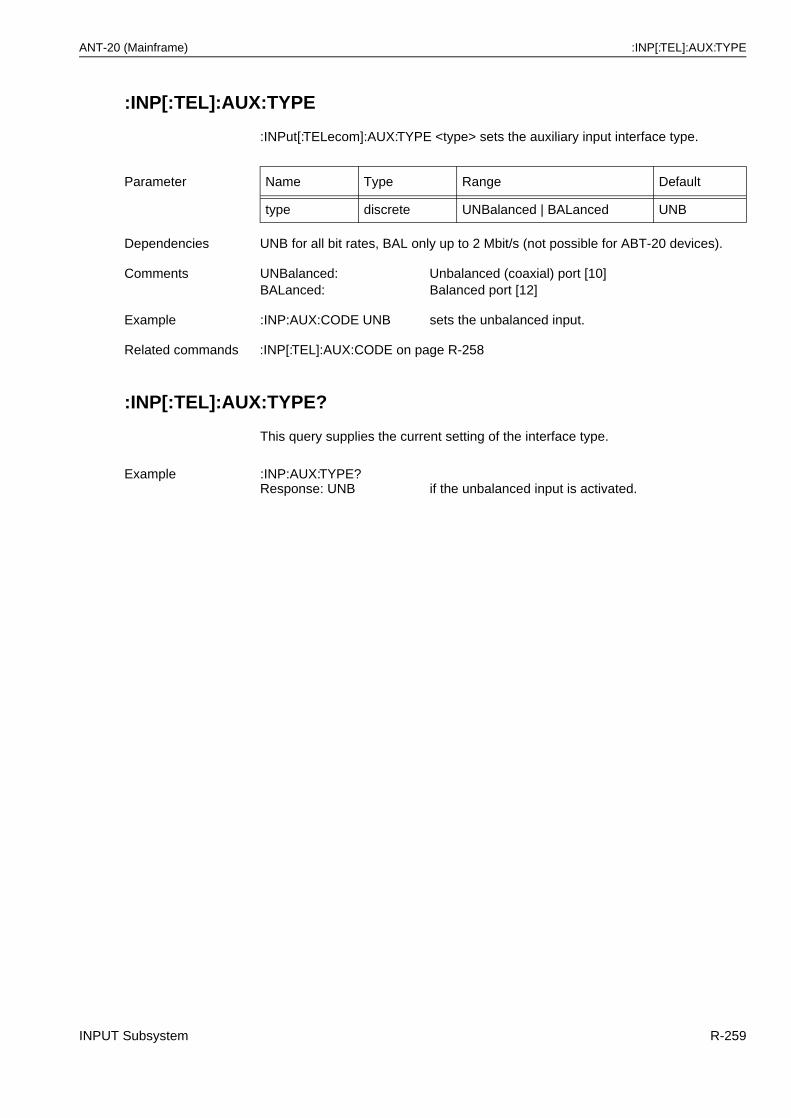
ANT-20 (Mainframe) :INP[:TEL]:AUX:TYPE
:INP[:TEL]:AUX:TYPE
:INPut[:TELecom]:AUX:TYPE <type> sets the auxiliary input interface type.
:INP[:TEL]:AUX:TYPE?
This query supplies the current setting of the interface type.
Parameter Name Type Range Default
type discrete UNBalanced | BALanced UNB
Dependencies UNB for all bit rates, BAL only up to 2 Mbit/s (not possible for ABT-20 devices).
Comments UNBalanced: Unbalanced (coaxial) port [10]BALanced: Balanced port [12]
Example :INP:AUX:CODE UNB sets the unbalanced input.
Related commands :INP[:TEL]:AUX:CODE on page R-258
Example :INP:AUX:TYPE?Response: UNB if the unbalanced input is activated.
INPUT Subsystem R-259
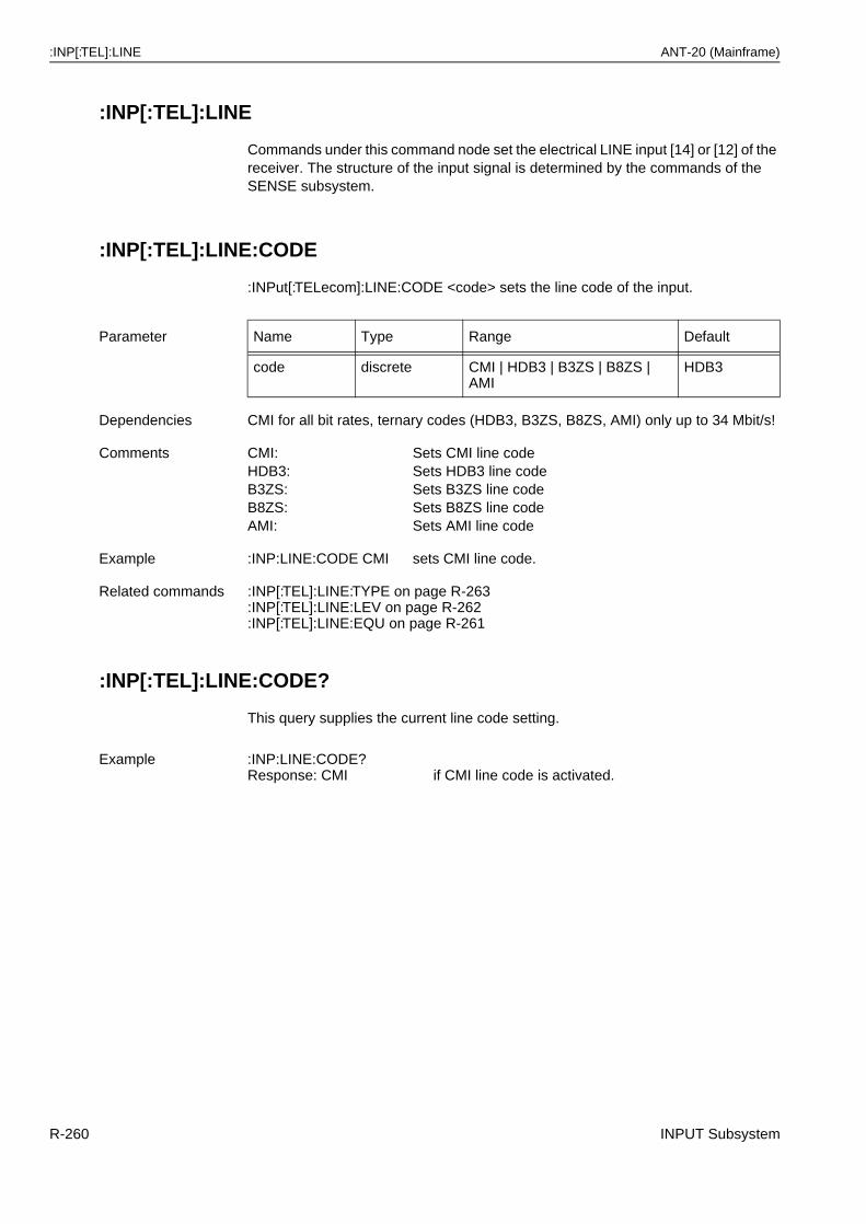
:INP[:TEL]:LINE ANT-20 (Mainframe)
:INP[:TEL]:LINE
Commands under this command node set the electrical LINE input [14] or [12] of the receiver. The structure of the input signal is determined by the commands of the SENSE subsystem.
:INP[:TEL]:LINE:CODE
:INPut[:TELecom]:LINE:CODE <code> sets the line code of the input.
:INP[:TEL]:LINE:CODE?
This query supplies the current line code setting.
Parameter Name Type Range Default
code discrete CMI | HDB3 | B3ZS | B8ZS | AMI
HDB3
Dependencies CMI for all bit rates, ternary codes (HDB3, B3ZS, B8ZS, AMI) only up to 34 Mbit/s!
Comments CMI: Sets CMI line codeHDB3: Sets HDB3 line codeB3ZS: Sets B3ZS line codeB8ZS: Sets B8ZS line codeAMI: Sets AMI line code
Example :INP:LINE:CODE CMI sets CMI line code.
Related commands :INP[:TEL]:LINE:TYPE on page R-263:INP[:TEL]:LINE:LEV on page R-262:INP[:TEL]:LINE:EQU on page R-261
Example :INP:LINE:CODE?Response: CMI if CMI line code is activated.
R-260 INPUT Subsystem
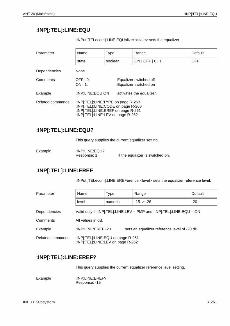
ANT-20 (Mainframe) :INP[:TEL]:LINE:EQU
:INP[:TEL]:LINE:EQU
:INPut[:TELecom]:LINE:EQUalizer <state> sets the equalizer.
:INP[:TEL]:LINE:EQU?
This query supplies the current equalizer setting.
:INP[:TEL]:LINE:EREF
:INPut[:TELecom]:LINE:EREFerence <level> sets the equalizer reference level.
:INP[:TEL]:LINE:EREF?
This query supplies the current equalizer reference level setting.
Parameter Name Type Range Default
state boolean ON | OFF | 0 | 1 OFF
Dependencies None
Comments OFF | 0: Equalizer switched offON | 1: Equalizer switched on
Example :INP:LINE:EQU ON activates the equalizer.
Related commands :INP[:TEL]:LINE:TYPE on page R-263:INP[:TEL]:LINE:CODE on page R-260:INP[:TEL]:LINE:EREF on page R-261:INP[:TEL]:LINE:LEV on page R-262
Example :INP:LINE:EQU?Response: 1 if the equalizer is switched on.
Parameter Name Type Range Default
level numeric -15 -> -26 -20
Dependencies Valid only if :INP[:TEL]:LINE:LEV = PMP and :INP[:TEL]:LINE:EQU = ON.
Comments All values in dB.
Example :INP:LINE:EREF -20 sets an equalizer reference level of -20 dB.
Related commands :INP[:TEL]:LINE:EQU on page R-261:INP[:TEL]:LINE:LEV on page R-262
Example :INP:LINE:EREF?Response: -15
INPUT Subsystem R-261
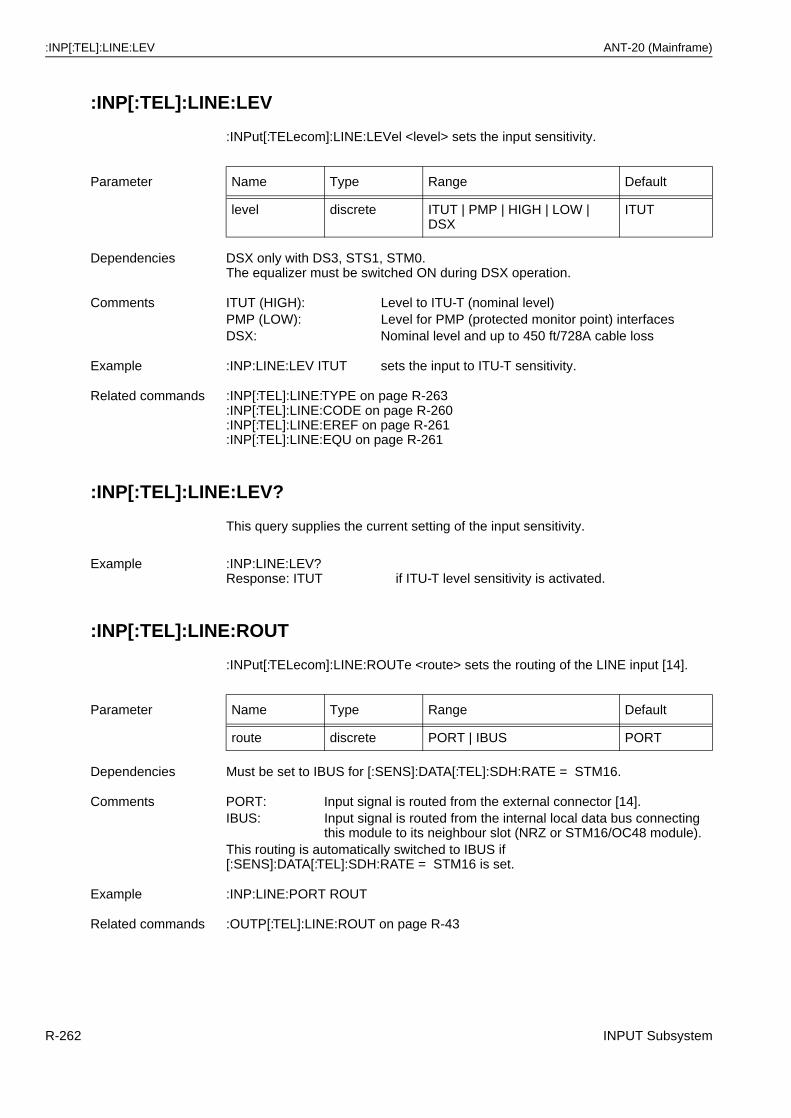
:INP[:TEL]:LINE:LEV ANT-20 (Mainframe)
:INP[:TEL]:LINE:LEV
:INPut[:TELecom]:LINE:LEVel <level> sets the input sensitivity.
:INP[:TEL]:LINE:LEV?
This query supplies the current setting of the input sensitivity.
:INP[:TEL]:LINE:ROUT
:INPut[:TELecom]:LINE:ROUTe <route> sets the routing of the LINE input [14].
Parameter Name Type Range Default
level discrete ITUT | PMP | HIGH | LOW | DSX
ITUT
Dependencies DSX only with DS3, STS1, STM0.The equalizer must be switched ON during DSX operation.
Comments ITUT (HIGH): Level to ITU-T (nominal level)PMP (LOW): Level for PMP (protected monitor point) interfacesDSX: Nominal level and up to 450 ft/728A cable loss
Example :INP:LINE:LEV ITUT sets the input to ITU-T sensitivity.
Related commands :INP[:TEL]:LINE:TYPE on page R-263:INP[:TEL]:LINE:CODE on page R-260:INP[:TEL]:LINE:EREF on page R-261:INP[:TEL]:LINE:EQU on page R-261
Example :INP:LINE:LEV?Response: ITUT if ITU-T level sensitivity is activated.
Parameter Name Type Range Default
route discrete PORT | IBUS PORT
Dependencies Must be set to IBUS for [:SENS]:DATA[:TEL]:SDH:RATE = STM16.
Comments PORT: Input signal is routed from the external connector [14].IBUS: Input signal is routed from the internal local data bus connecting
this module to its neighbour slot (NRZ or STM16/OC48 module).This routing is automatically switched to IBUS if [:SENS]:DATA[:TEL]:SDH:RATE = STM16 is set.
Example :INP:LINE:PORT ROUT
Related commands :OUTP[:TEL]:LINE:ROUT on page R-43
R-262 INPUT Subsystem
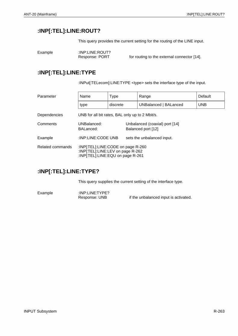
ANT-20 (Mainframe) :INP[:TEL]:LINE:ROUT?
:INP[:TEL]:LINE:ROUT?
This query provides the current setting for the routing of the LINE input.
:INP[:TEL]:LINE:TYPE
:INPut[:TELecom]:LINE:TYPE <type> sets the interface type of the input.
:INP[:TEL]:LINE:TYPE?
This query supplies the current setting of the interface type.
Example :INP:LINE:ROUT?Response: PORT for routing to the external connector [14].
Parameter Name Type Range Default
type discrete UNBalanced | BALanced UNB
Dependencies UNB for all bit rates, BAL only up to 2 Mbit/s.
Comments UNBalanced: Unbalanced (coaxial) port [14]BALanced: Balanced port [12]
Example :INP:LINE:CODE UNB sets the unbalanced input.
Related commands :INP[:TEL]:LINE:CODE on page R-260:INP[:TEL]:LINE:LEV on page R-262:INP[:TEL]:LINE:EQU on page R-261
Example :INP:LINE:TYPE?Response: UNB if the unbalanced input is activated.
INPUT Subsystem R-263
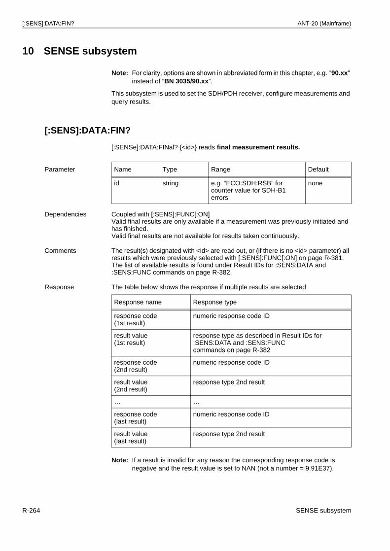
[:SENS]:DATA:FIN? ANT-20 (Mainframe)
10 SENSE subsystem
Note: For clarity, options are shown in abbreviated form in this chapter, e.g. “90.xx” instead of “BN 3035/90.xx”.
This subsystem is used to set the SDH/PDH receiver, configure measurements and query results.
[:SENS]:DATA:FIN?
[:SENSe]:DATA:FINal? {<id>} reads final measurement results.
Note: If a result is invalid for any reason the corresponding response code is negative and the result value is set to NAN (not a number = 9.91E37).
Parameter Name Type Range Default
id string e.g. “ECO:SDH:RSB” for counter value for SDH-B1 errors
none
Dependencies Coupled with [:SENS]:FUNC[:ON]Valid final results are only available if a measurement was previously initiated and has finished.Valid final results are not available for results taken continuously.
Comments The result(s) designated with <id> are read out, or (if there is no <id> parameter) all results which were previously selected with [:SENS]:FUNC[:ON] on page R-381.The list of available results is found under Result IDs for :SENS:DATA and :SENS:FUNC commands on page R-382.
Response The table below shows the response if multiple results are selected
Response name Response type
response code(1st result)
numeric response code ID
result value(1st result)
response type as described in Result IDs for :SENS:DATA and :SENS:FUNC commands on page R-382
response code(2nd result)
numeric response code ID
result value(2nd result)
response type 2nd result
… …
response code(last result)
numeric response code ID
result value(last result)
response type 2nd result
R-264 SENSE subsystem
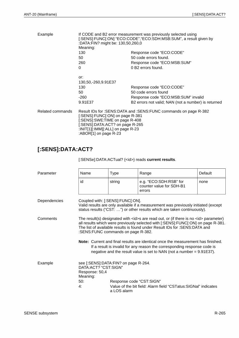
ANT-20 (Mainframe) [:SENS]:DATA:ACT?
[:SENS]:DATA:ACT?
[:SENSe]:DATA:ACTual? {<id>} reads current results.
Note: Current and final results are identical once the measurement has finished.If a result is invalid for any reason the corresponding response code is negative and the result value is set to NAN (not a number = 9.91E37).
Example If CODE and B2 error measurement was previously selected using [:SENS]:FUNC[:ON] “ECO:CODE”,“ECO:SDH:MSB:SUM”, a result given by :DATA:FIN? might be: 130,50,260,0Meaning:130 Response code “ECO:CODE”50 50 code errors found.260 Response code “ECO:MSB:SUM”0 0 B2 errors found.
or:130,50,-260,9.91E37130 Response code “ECO:CODE”50 50 code errors found-260 Response code “ECO:MSB:SUM” invalid9.91E37 B2 errors not valid; NAN (not a number) is returned
Related commands Result IDs for :SENS:DATA and :SENS:FUNC commands on page R-382[:SENS]:FUNC[:ON] on page R-381[:SENS]:SWE:TIME on page R-408[:SENS]:DATA:ACT? on page R-265:INIT[1][:IMM][:ALL] on page R-23:ABOR[1] on page R-23
Parameter Name Type Range Default
id string e.g. “ECO:SDH:RSB” for counter value for SDH-B1 errors
none
Dependencies Coupled with: [:SENS]:FUNC[:ON].Valid results are only available if a measurement was previously initiated (except status results (“CST: …”) or other results which are taken continuously).
Comments The result(s) designated with <id>s are read out, or (if there is no <id> parameter) all results which were previously selected with [:SENS]:FUNC[:ON] on page R-381.The list of available results is found under Result IDs for :SENS:DATA and :SENS:FUNC commands on page R-382.
Example see [:SENS]:DATA:FIN? on page R-264.DATA:ACT? “CST:SIGN”Response: 50,4Meaning:50: Response code “CST:SIGN”4: Value of the bit field: Alarm field “CSTatus:SIGNal” indicates
a LOS alarm
SENSE subsystem R-265
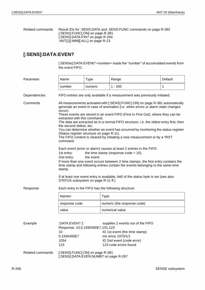
[:SENS]:DATA:EVEN? ANT-20 (Mainframe)
[:SENS]:DATA:EVEN?
[:SENSe]:DATA:EVENt? <number> reads the “number” of accumulated events from the event FIFO.
Related commands Result IDs for :SENS:DATA and :SENS:FUNC commands on page R-382[:SENS]:FUNC[:ON] on page R-381[:SENS]:DATA:FIN? on page R-264:INIT[1][:IMM][:ALL] on page R-23
Parameter Name Type Range Default
number numeric 1 - 200 1
Dependencies FIFO entries are only available if a measurement was previously initiated.
Comments All measurements activated with [:SENS]:FUNC[:ON] on page R-381 automatically generate an event in case of anomalies (i.e. when errors or alarm state changes occur). These events are stored in an event FIFO (First In First Out), where they can be extracted with this command.The data are extracted as in a normal FIFO structure, i.e. the oldest entry first, then the second oldest, etc.You can determine whether an event has occurred by monitoring the status register (Status register structure on page R-11).The FIFO content is cleared by initiating a new measurement or by a *RST command.
Each event (error or alarm) causes at least 2 entries in the FIFO:1st entry: the time stamp (response code = 10).2nd entry: the event.If more than one event occurs between 2 time stamps, the first entry contains the time stamp and following entries contain the events belonging to the same time stamp.
If at least one event entry is available, bit0 of the status byte is set (see also STATUS subsystem on page R-11 ff.)
Response Each entry in the FIFO has the following structure:
Namen Type
response code numeric (the response code)
value numerical value
Example :DATA:EVEN? 2 supplies 2 events out of the FIFOResponse: 10,0.1930400E7,101,12310 ID 1st event (the time stamp)0.1930400E7 ms since 1970/1/11054 ID 2nd event (code error)123 123 code errors found
Related commands [:SENS]:FUNC[:ON] on page R-381[:SENS]:DATA:EVEN:NUMB? on page R-267
R-266 SENSE subsystem
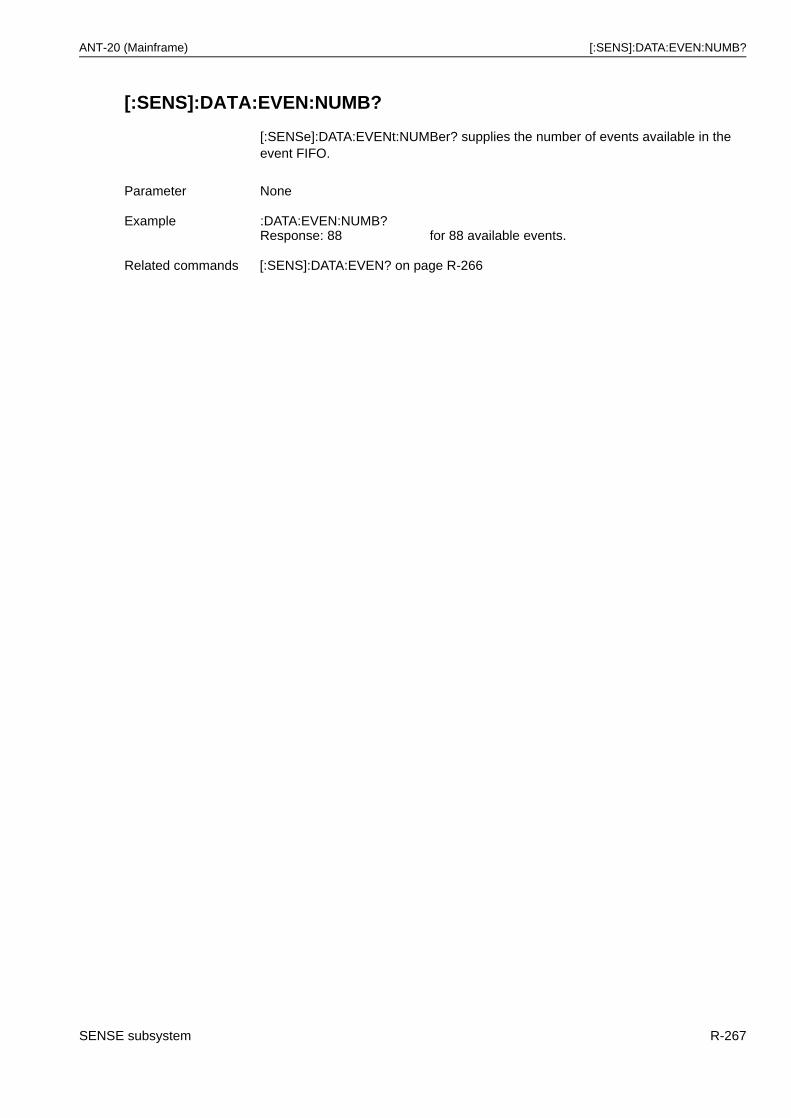
ANT-20 (Mainframe) [:SENS]:DATA:EVEN:NUMB?
[:SENS]:DATA:EVEN:NUMB?
[:SENSe]:DATA:EVENt:NUMBer? supplies the number of events available in the event FIFO.
Parameter None
Example :DATA:EVEN:NUMB?Response: 88 for 88 available events.
Related commands [:SENS]:DATA:EVEN? on page R-266
SENSE subsystem R-267
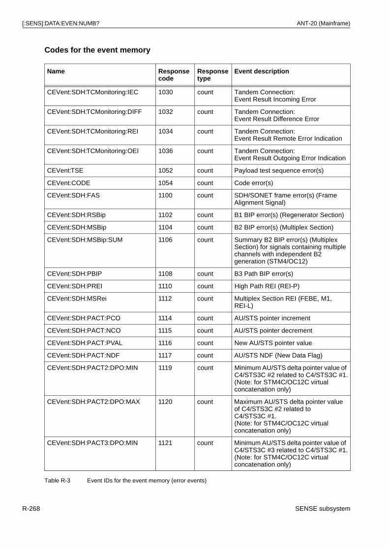
[:SENS]:DATA:EVEN:NUMB? ANT-20 (Mainframe)
Codes for the event memory
Name Response code
Response type
Event description
CEVent:SDH:TCMonitoring:IEC 1030 count Tandem Connection:Event Result Incoming Error
CEVent:SDH:TCMonitoring:DIFF 1032 count Tandem Connection:Event Result Difference Error
CEVent:SDH:TCMonitoring:REI 1034 count Tandem Connection:Event Result Remote Error Indication
CEVent:SDH:TCMonitoring:OEI 1036 count Tandem Connection:Event Result Outgoing Error Indication
CEVent:TSE 1052 count Payload test sequence error(s)
CEVent:CODE 1054 count Code error(s)
CEVent:SDH:FAS 1100 count SDH/SONET frame error(s) (Frame Alignment Signal)
CEVent:SDH:RSBip 1102 count B1 BIP error(s) (Regenerator Section)
CEVent:SDH:MSBip 1104 count B2 BIP error(s) (Multiplex Section)
CEVent:SDH:MSBip:SUM 1106 count Summary B2 BIP error(s) (Multiplex Section) for signals containing multiple channels with independent B2 generation (STM4/OC12)
CEVent:SDH:PBIP 1108 count B3 Path BIP error(s)
CEVent:SDH:PREI 1110 count High Path REI (REI-P)
CEVent:SDH:MSRei 1112 count Multiplex Section REI (FEBE, M1, REI-L)
CEVent:SDH:PACT:PCO 1114 count AU/STS pointer increment
CEVent:SDH:PACT:NCO 1115 count AU/STS pointer decrement
CEVent:SDH:PACT:PVAL 1116 count New AU/STS pointer value
CEVent:SDH:PACT:NDF 1117 count AU/STS NDF (New Data Flag)
CEVent:SDH:PACT2:DPO:MIN 1119 count Minimum AU/STS delta pointer value of C4/STS3C #2 related to C4/STS3C #1.(Note: for STM4C/OC12C virtual concatenation only)
CEVent:SDH:PACT2:DPO:MAX 1120 count Maximum AU/STS delta pointer value of C4/STS3C #2 related to C4/STS3C #1.(Note: for STM4C/OC12C virtual concatenation only)
CEVent:SDH:PACT3:DPO:MIN 1121 count Minimum AU/STS delta pointer value of C4/STS3C #3 related to C4/STS3C #1.(Note: for STM4C/OC12C virtual concatenation only)
Table R-3 Event IDs for the event memory (error events)
R-268 SENSE subsystem
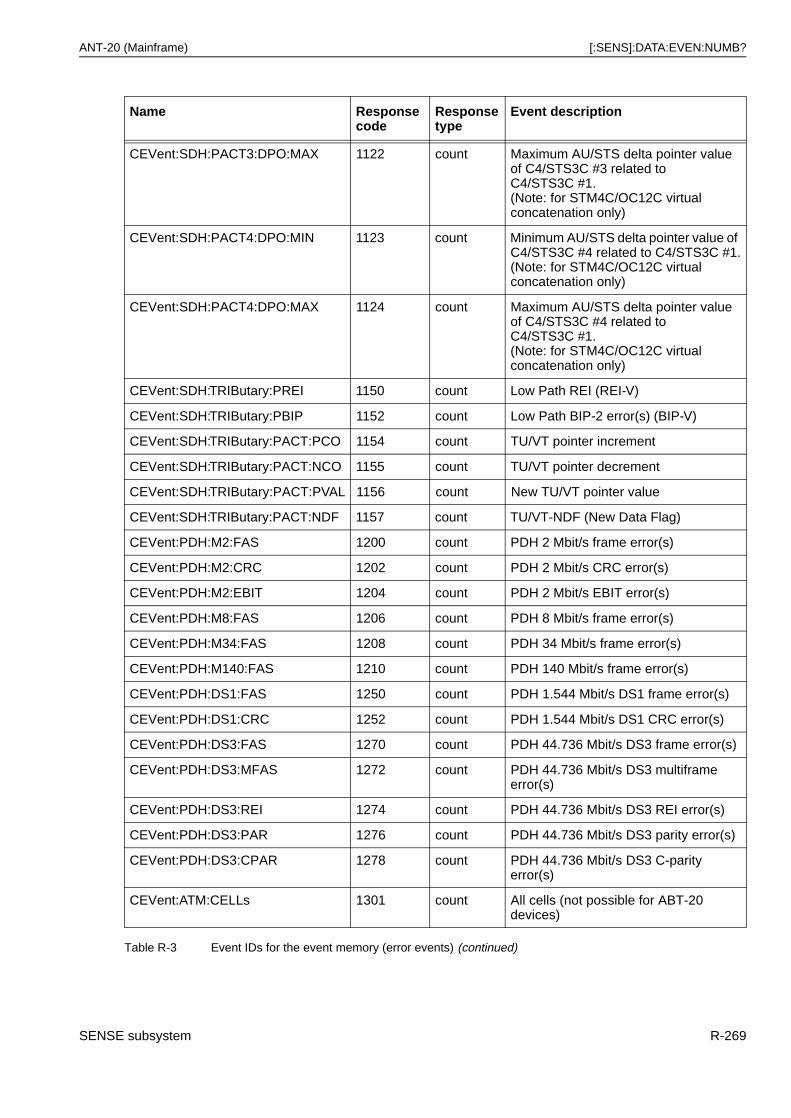
ANT-20 (Mainframe) [:SENS]:DATA:EVEN:NUMB?
CEVent:SDH:PACT3:DPO:MAX 1122 count Maximum AU/STS delta pointer value of C4/STS3C #3 related to C4/STS3C #1.(Note: for STM4C/OC12C virtual concatenation only)
CEVent:SDH:PACT4:DPO:MIN 1123 count Minimum AU/STS delta pointer value of C4/STS3C #4 related to C4/STS3C #1.(Note: for STM4C/OC12C virtual concatenation only)
CEVent:SDH:PACT4:DPO:MAX 1124 count Maximum AU/STS delta pointer value of C4/STS3C #4 related to C4/STS3C #1.(Note: for STM4C/OC12C virtual concatenation only)
CEVent:SDH:TRIButary:PREI 1150 count Low Path REI (REI-V)
CEVent:SDH:TRIButary:PBIP 1152 count Low Path BIP-2 error(s) (BIP-V)
CEVent:SDH:TRIButary:PACT:PCO 1154 count TU/VT pointer increment
CEVent:SDH:TRIButary:PACT:NCO 1155 count TU/VT pointer decrement
CEVent:SDH:TRIButary:PACT:PVAL 1156 count New TU/VT pointer value
CEVent:SDH:TRIButary:PACT:NDF 1157 count TU/VT-NDF (New Data Flag)
CEVent:PDH:M2:FAS 1200 count PDH 2 Mbit/s frame error(s)
CEVent:PDH:M2:CRC 1202 count PDH 2 Mbit/s CRC error(s)
CEVent:PDH:M2:EBIT 1204 count PDH 2 Mbit/s EBIT error(s)
CEVent:PDH:M8:FAS 1206 count PDH 8 Mbit/s frame error(s)
CEVent:PDH:M34:FAS 1208 count PDH 34 Mbit/s frame error(s)
CEVent:PDH:M140:FAS 1210 count PDH 140 Mbit/s frame error(s)
CEVent:PDH:DS1:FAS 1250 count PDH 1.544 Mbit/s DS1 frame error(s)
CEVent:PDH:DS1:CRC 1252 count PDH 1.544 Mbit/s DS1 CRC error(s)
CEVent:PDH:DS3:FAS 1270 count PDH 44.736 Mbit/s DS3 frame error(s)
CEVent:PDH:DS3:MFAS 1272 count PDH 44.736 Mbit/s DS3 multiframe error(s)
CEVent:PDH:DS3:REI 1274 count PDH 44.736 Mbit/s DS3 REI error(s)
CEVent:PDH:DS3:PAR 1276 count PDH 44.736 Mbit/s DS3 parity error(s)
CEVent:PDH:DS3:CPAR 1278 count PDH 44.736 Mbit/s DS3 C-parity error(s)
CEVent:ATM:CELLs 1301 count All cells (not possible for ABT-20 devices)
Name Response code
Response type
Event description
Table R-3 Event IDs for the event memory (error events) (continued)
SENSE subsystem R-269
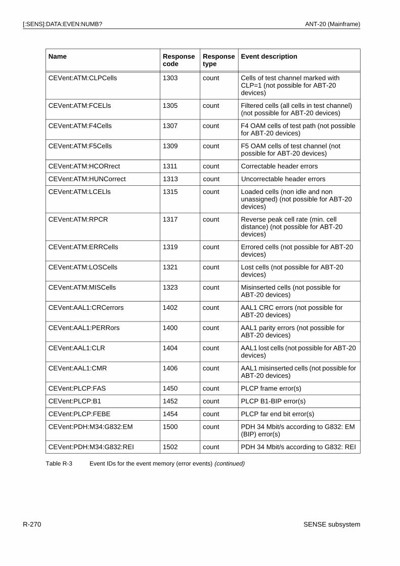
[:SENS]:DATA:EVEN:NUMB? ANT-20 (Mainframe)
CEVent:ATM:CLPCells 1303 count Cells of test channel marked with CLP=1 (not possible for ABT-20 devices)
CEVent:ATM:FCELls 1305 count Filtered cells (all cells in test channel) (not possible for ABT-20 devices)
CEVent:ATM:F4Cells 1307 count F4 OAM cells of test path (not possible for ABT-20 devices)
CEVent:ATM:F5Cells 1309 count F5 OAM cells of test channel (not possible for ABT-20 devices)
CEVent:ATM:HCORrect 1311 count Correctable header errors
CEVent:ATM:HUNCorrect 1313 count Uncorrectable header errors
CEVent:ATM:LCELls 1315 count Loaded cells (non idle and non unassigned) (not possible for ABT-20 devices)
CEVent:ATM:RPCR 1317 count Reverse peak cell rate (min. cell distance) (not possible for ABT-20 devices)
CEVent:ATM:ERRCells 1319 count Errored cells (not possible for ABT-20 devices)
CEVent:ATM:LOSCells 1321 count Lost cells (not possible for ABT-20 devices)
CEVent:ATM:MISCells 1323 count Misinserted cells (not possible for ABT-20 devices)
CEVent:AAL1:CRCerrors 1402 count AAL1 CRC errors (not possible for ABT-20 devices)
CEVent:AAL1:PERRors 1400 count AAL1 parity errors (not possible for ABT-20 devices)
CEVent:AAL1:CLR 1404 count AAL1 lost cells (not possible for ABT-20 devices)
CEVent:AAL1:CMR 1406 count AAL1 misinserted cells (not possible for ABT-20 devices)
CEVent:PLCP:FAS 1450 count PLCP frame error(s)
CEVent:PLCP:B1 1452 count PLCP B1-BIP error(s)
CEVent:PLCP:FEBE 1454 count PLCP far end bit error(s)
CEVent:PDH:M34:G832:EM 1500 count PDH 34 Mbit/s according to G832: EM (BIP) error(s)
CEVent:PDH:M34:G832:REI 1502 count PDH 34 Mbit/s according to G832: REI
Name Response code
Response type
Event description
Table R-3 Event IDs for the event memory (error events) (continued)
R-270 SENSE subsystem

ANT-20 (Mainframe) [:SENS]:DATA:EVEN:NUMB?
Note: The alarm alternation events are combined into groups of bit fields (32 bits) in which each individual alarm can be found in a specified bit position. These groups are composed of alarms which logically belong together. A logical “1” at the respective bit position indicates an active alarm, and a logical “0” an inactive alarm. For a description of these groups, see: Alarm bit fields on page R-272 ff.
CEVent:PDH:M140:G832:EM 1504 count PDH 140 Mbit/s according to G832: EM (BIP) error(s)
CEVent:PDH:M140:G832:REI 1506 count PDH 140 Mbit/s according to G832: REI
CEVent: COUNT Event (Errors occurred)
Name Response code
Response type Event description
AEVent:SIGNal 1000 boolean (compressed)
Event in the signal alarm bit field (see also Alarm field “CSTatus:SIGNal” on page R-272)
AEVent:SDH 1001 boolean (compressed)
Event in the SDH alarm bit field (see also Alarm field “CSTatus:SDH”/“HSTatus:SDH” on page R-272)
AEVent:SDH2 1002 boolean (compressed)
Event in the SDH alarm bit field (see also Alarm field “CSTatus:SDH2”/“HSTatus:SDH2” on page R-274)
AEVent:PDH 1010 boolean (compressed)
Event in the PDH alarm bit field (see also Alarm field “CSTatus:PDH”/“HSTatus:PDH” on page R-278)
AEVent:PDH2 1011 boolean (compressed)
Event in the PDH alarm bit field (see also Alarm field “CSTatus:PDH2”/“HSTatus:PDH2” on page R-279 (DS1, DS3)
AEVent:ATM 1300 boolean Alarm change for ATM measurements
Table R-4 Other event IDs for the event memory (alarm alternation events)
Name Response code
Response type Event description
NOEVent 0 count = 0 No event available
OVERflow 1 count = 0 Overflow of internal event memory
Time stamp 10 count Time stamp of events in milliseconds since 1/1/1970
Table R-5 General event IDs for the event memory
Name Response code
Response type
Event description
Table R-3 Event IDs for the event memory (error events) (continued)
SENSE subsystem R-271
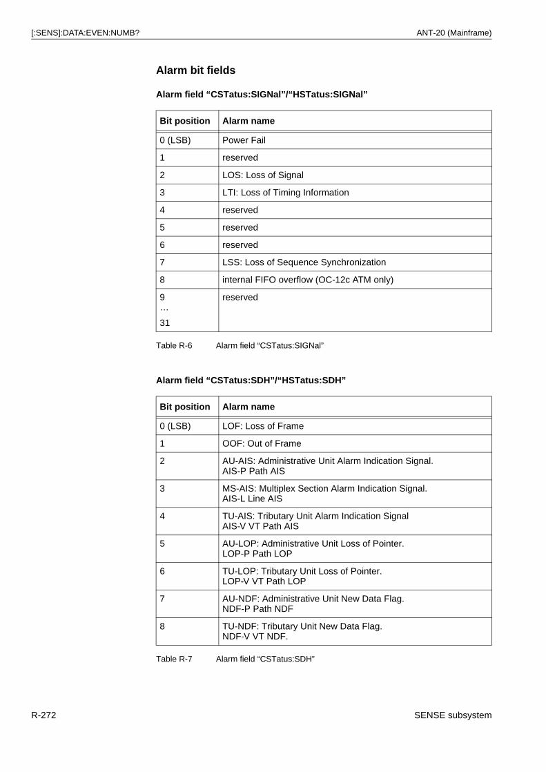
[:SENS]:DATA:EVEN:NUMB? ANT-20 (Mainframe)
Alarm bit fields
Alarm field “CSTatus:SIGNal”/“HSTatus:SIGNal”
Alarm field “CSTatus:SDH”/“HSTatus:SDH”
Bit position Alarm name
0 (LSB) Power Fail
1 reserved
2 LOS: Loss of Signal
3 LTI: Loss of Timing Information
4 reserved
5 reserved
6 reserved
7 LSS: Loss of Sequence Synchronization
8 internal FIFO overflow (OC-12c ATM only)
9…
31
reserved
Table R-6 Alarm field “CSTatus:SIGNal”
Bit position Alarm name
0 (LSB) LOF: Loss of Frame
1 OOF: Out of Frame
2 AU-AIS: Administrative Unit Alarm Indication Signal.AIS-P Path AIS
3 MS-AIS: Multiplex Section Alarm Indication Signal.AIS-L Line AIS
4 TU-AIS: Tributary Unit Alarm Indication SignalAIS-V VT Path AIS
5 AU-LOP: Administrative Unit Loss of Pointer.LOP-P Path LOP
6 TU-LOP: Tributary Unit Loss of Pointer.LOP-V VT Path LOP
7 AU-NDF: Administrative Unit New Data Flag.NDF-P Path NDF
8 TU-NDF: Tributary Unit New Data Flag.NDF-V VT NDF.
Table R-7 Alarm field “CSTatus:SDH”
R-272 SENSE subsystem
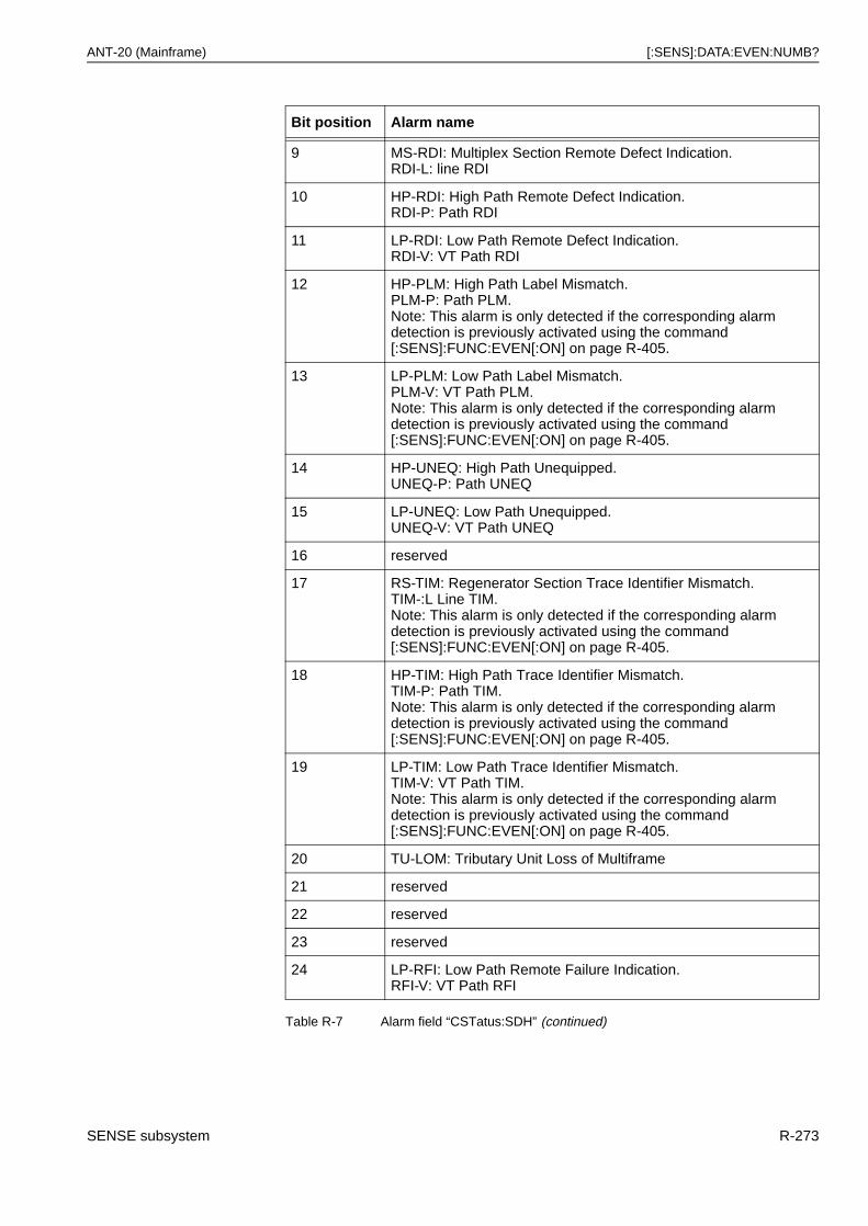
ANT-20 (Mainframe) [:SENS]:DATA:EVEN:NUMB?
9 MS-RDI: Multiplex Section Remote Defect Indication.RDI-L: line RDI
10 HP-RDI: High Path Remote Defect Indication.RDI-P: Path RDI
11 LP-RDI: Low Path Remote Defect Indication.RDI-V: VT Path RDI
12 HP-PLM: High Path Label Mismatch.PLM-P: Path PLM.Note: This alarm is only detected if the corresponding alarm detection is previously activated using the command [:SENS]:FUNC:EVEN[:ON] on page R-405.
13 LP-PLM: Low Path Label Mismatch.PLM-V: VT Path PLM.Note: This alarm is only detected if the corresponding alarm detection is previously activated using the command [:SENS]:FUNC:EVEN[:ON] on page R-405.
14 HP-UNEQ: High Path Unequipped.UNEQ-P: Path UNEQ
15 LP-UNEQ: Low Path Unequipped.UNEQ-V: VT Path UNEQ
16 reserved
17 RS-TIM: Regenerator Section Trace Identifier Mismatch.TIM-:L Line TIM.Note: This alarm is only detected if the corresponding alarm detection is previously activated using the command [:SENS]:FUNC:EVEN[:ON] on page R-405.
18 HP-TIM: High Path Trace Identifier Mismatch.TIM-P: Path TIM.Note: This alarm is only detected if the corresponding alarm detection is previously activated using the command [:SENS]:FUNC:EVEN[:ON] on page R-405.
19 LP-TIM: Low Path Trace Identifier Mismatch.TIM-V: VT Path TIM.Note: This alarm is only detected if the corresponding alarm detection is previously activated using the command [:SENS]:FUNC:EVEN[:ON] on page R-405.
20 TU-LOM: Tributary Unit Loss of Multiframe
21 reserved
22 reserved
23 reserved
24 LP-RFI: Low Path Remote Failure Indication.RFI-V: VT Path RFI
Bit position Alarm name
Table R-7 Alarm field “CSTatus:SDH” (continued)
SENSE subsystem R-273
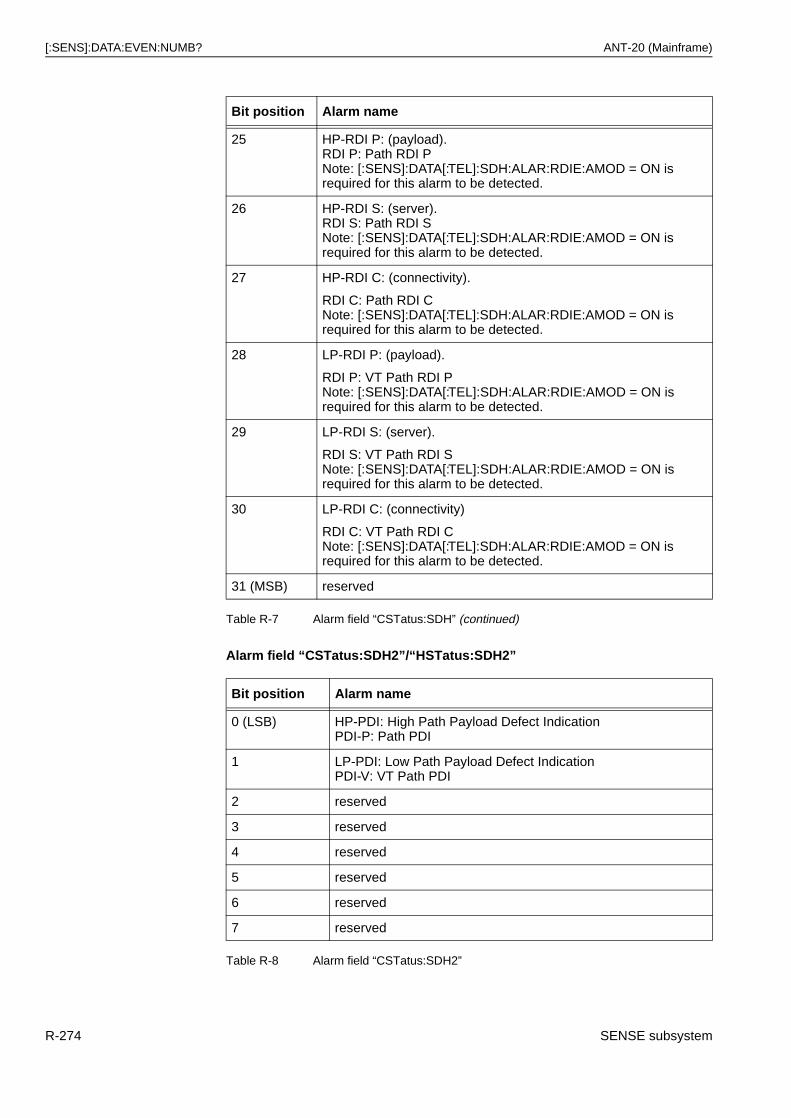
[:SENS]:DATA:EVEN:NUMB? ANT-20 (Mainframe)
Alarm field “CSTatus:SDH2”/“HSTatus:SDH2”
25 HP-RDI P: (payload).RDI P: Path RDI PNote: [:SENS]:DATA[:TEL]:SDH:ALAR:RDIE:AMOD = ON is required for this alarm to be detected.
26 HP-RDI S: (server).RDI S: Path RDI SNote: [:SENS]:DATA[:TEL]:SDH:ALAR:RDIE:AMOD = ON is required for this alarm to be detected.
27 HP-RDI C: (connectivity).
RDI C: Path RDI CNote: [:SENS]:DATA[:TEL]:SDH:ALAR:RDIE:AMOD = ON is required for this alarm to be detected.
28 LP-RDI P: (payload).
RDI P: VT Path RDI PNote: [:SENS]:DATA[:TEL]:SDH:ALAR:RDIE:AMOD = ON is required for this alarm to be detected.
29 LP-RDI S: (server).
RDI S: VT Path RDI SNote: [:SENS]:DATA[:TEL]:SDH:ALAR:RDIE:AMOD = ON is required for this alarm to be detected.
30 LP-RDI C: (connectivity)
RDI C: VT Path RDI CNote: [:SENS]:DATA[:TEL]:SDH:ALAR:RDIE:AMOD = ON is required for this alarm to be detected.
31 (MSB) reserved
Bit position Alarm name
0 (LSB) HP-PDI: High Path Payload Defect IndicationPDI-P: Path PDI
1 LP-PDI: Low Path Payload Defect IndicationPDI-V: VT Path PDI
2 reserved
3 reserved
4 reserved
5 reserved
6 reserved
7 reserved
Table R-8 Alarm field “CSTatus:SDH2”
Bit position Alarm name
Table R-7 Alarm field “CSTatus:SDH” (continued)
R-274 SENSE subsystem
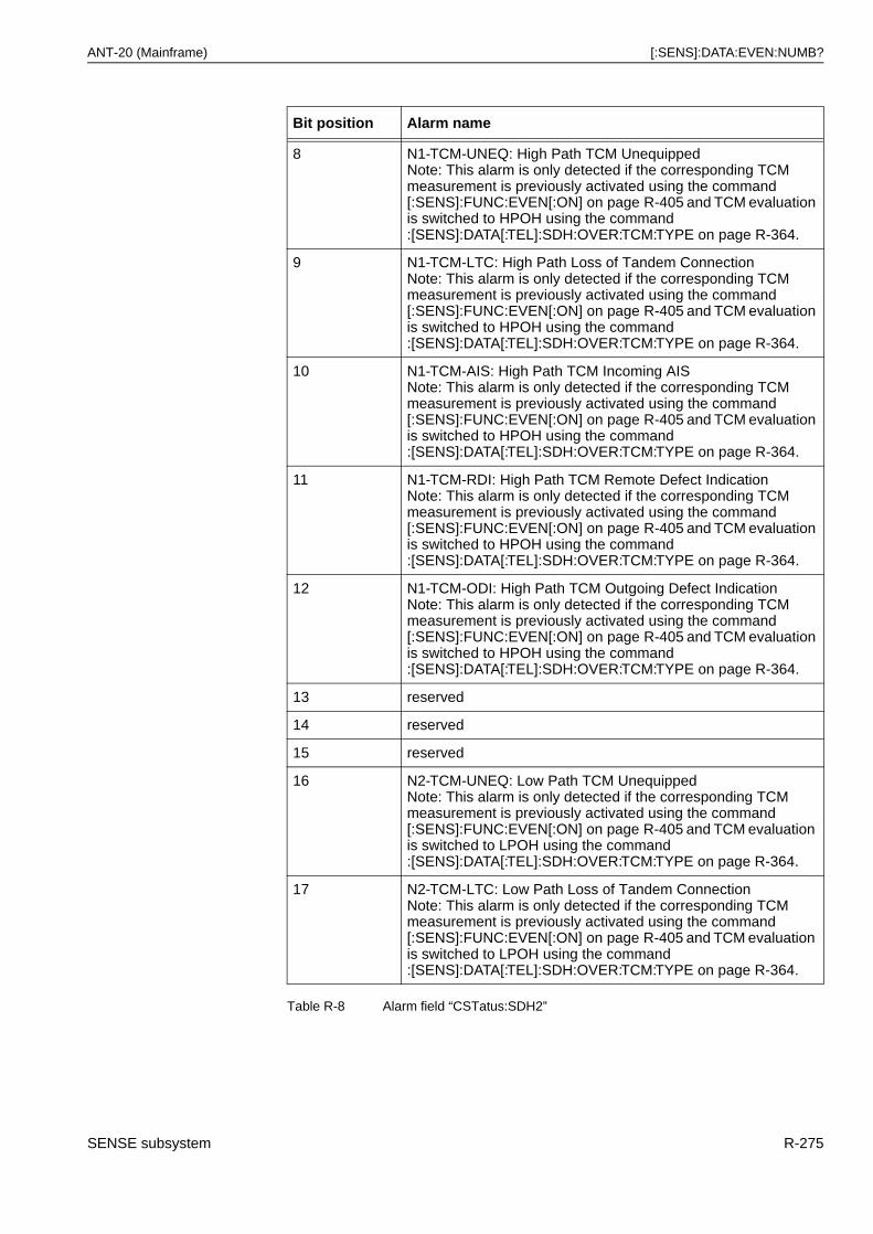
ANT-20 (Mainframe) [:SENS]:DATA:EVEN:NUMB?
8 N1-TCM-UNEQ: High Path TCM UnequippedNote: This alarm is only detected if the corresponding TCM measurement is previously activated using the command [:SENS]:FUNC:EVEN[:ON] on page R-405 and TCM evaluation is switched to HPOH using the command :[SENS]:DATA[:TEL]:SDH:OVER:TCM:TYPE on page R-364.
9 N1-TCM-LTC: High Path Loss of Tandem ConnectionNote: This alarm is only detected if the corresponding TCM measurement is previously activated using the command [:SENS]:FUNC:EVEN[:ON] on page R-405 and TCM evaluation is switched to HPOH using the command :[SENS]:DATA[:TEL]:SDH:OVER:TCM:TYPE on page R-364.
10 N1-TCM-AIS: High Path TCM Incoming AISNote: This alarm is only detected if the corresponding TCM measurement is previously activated using the command [:SENS]:FUNC:EVEN[:ON] on page R-405 and TCM evaluation is switched to HPOH using the command :[SENS]:DATA[:TEL]:SDH:OVER:TCM:TYPE on page R-364.
11 N1-TCM-RDI: High Path TCM Remote Defect IndicationNote: This alarm is only detected if the corresponding TCM measurement is previously activated using the command [:SENS]:FUNC:EVEN[:ON] on page R-405 and TCM evaluation is switched to HPOH using the command :[SENS]:DATA[:TEL]:SDH:OVER:TCM:TYPE on page R-364.
12 N1-TCM-ODI: High Path TCM Outgoing Defect IndicationNote: This alarm is only detected if the corresponding TCM measurement is previously activated using the command [:SENS]:FUNC:EVEN[:ON] on page R-405 and TCM evaluation is switched to HPOH using the command :[SENS]:DATA[:TEL]:SDH:OVER:TCM:TYPE on page R-364.
13 reserved
14 reserved
15 reserved
16 N2-TCM-UNEQ: Low Path TCM UnequippedNote: This alarm is only detected if the corresponding TCM measurement is previously activated using the command [:SENS]:FUNC:EVEN[:ON] on page R-405 and TCM evaluation is switched to LPOH using the command :[SENS]:DATA[:TEL]:SDH:OVER:TCM:TYPE on page R-364.
17 N2-TCM-LTC: Low Path Loss of Tandem ConnectionNote: This alarm is only detected if the corresponding TCM measurement is previously activated using the command [:SENS]:FUNC:EVEN[:ON] on page R-405 and TCM evaluation is switched to LPOH using the command :[SENS]:DATA[:TEL]:SDH:OVER:TCM:TYPE on page R-364.
Bit position Alarm name
Table R-8 Alarm field “CSTatus:SDH2”
SENSE subsystem R-275
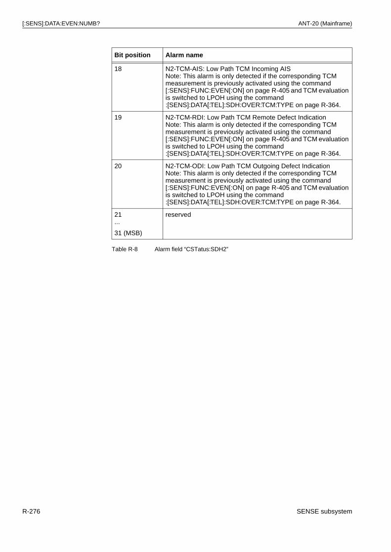
[:SENS]:DATA:EVEN:NUMB? ANT-20 (Mainframe)
18 N2-TCM-AIS: Low Path TCM Incoming AISNote: This alarm is only detected if the corresponding TCM measurement is previously activated using the command [:SENS]:FUNC:EVEN[:ON] on page R-405 and TCM evaluation is switched to LPOH using the command :[SENS]:DATA[:TEL]:SDH:OVER:TCM:TYPE on page R-364.
19 N2-TCM-RDI: Low Path TCM Remote Defect IndicationNote: This alarm is only detected if the corresponding TCM measurement is previously activated using the command [:SENS]:FUNC:EVEN[:ON] on page R-405 and TCM evaluation is switched to LPOH using the command :[SENS]:DATA[:TEL]:SDH:OVER:TCM:TYPE on page R-364.
20 N2-TCM-ODI: Low Path TCM Outgoing Defect IndicationNote: This alarm is only detected if the corresponding TCM measurement is previously activated using the command [:SENS]:FUNC:EVEN[:ON] on page R-405 and TCM evaluation is switched to LPOH using the command :[SENS]:DATA[:TEL]:SDH:OVER:TCM:TYPE on page R-364.
21 ...
31 (MSB)
reserved
Bit position Alarm name
Table R-8 Alarm field “CSTatus:SDH2”
R-276 SENSE subsystem
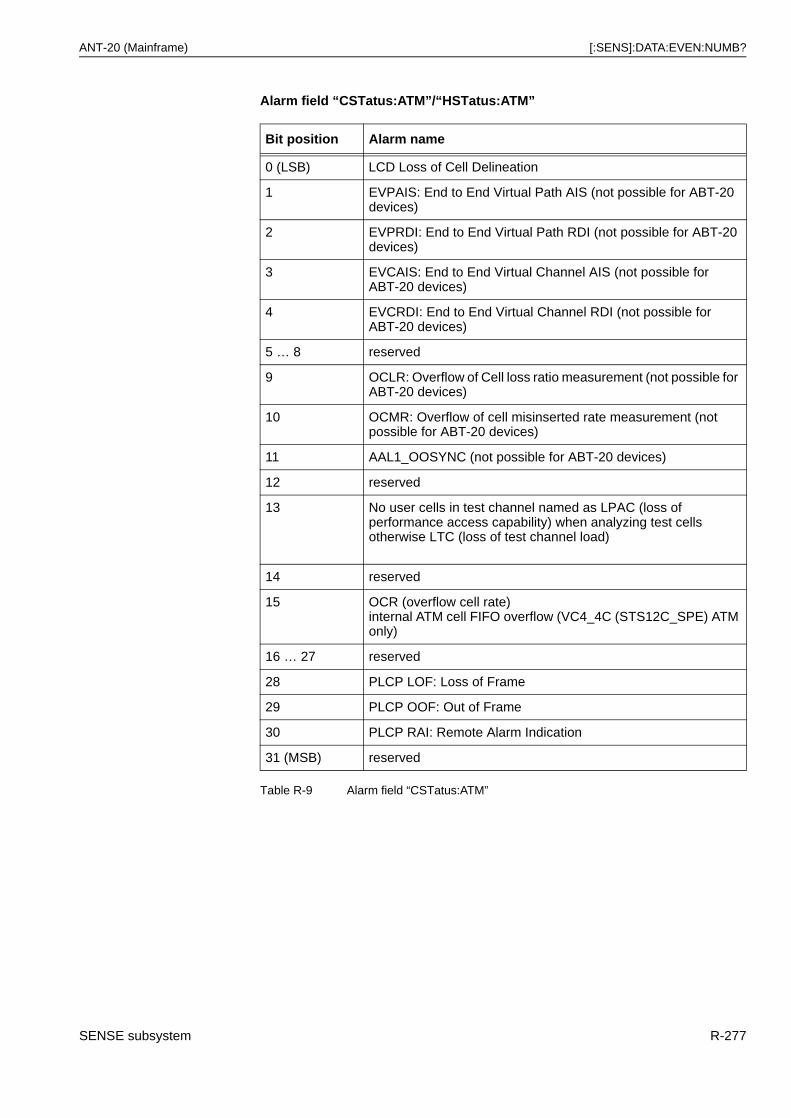
ANT-20 (Mainframe) [:SENS]:DATA:EVEN:NUMB?
Alarm field “CSTatus:ATM”/“HSTatus:ATM”
Bit position Alarm name
0 (LSB) LCD Loss of Cell Delineation
1 EVPAIS: End to End Virtual Path AIS (not possible for ABT-20 devices)
2 EVPRDI: End to End Virtual Path RDI (not possible for ABT-20 devices)
3 EVCAIS: End to End Virtual Channel AIS (not possible for ABT-20 devices)
4 EVCRDI: End to End Virtual Channel RDI (not possible for ABT-20 devices)
5 … 8 reserved
9 OCLR: Overflow of Cell loss ratio measurement (not possible for ABT-20 devices)
10 OCMR: Overflow of cell misinserted rate measurement (not possible for ABT-20 devices)
11 AAL1_OOSYNC (not possible for ABT-20 devices)
12 reserved
13 No user cells in test channel named as LPAC (loss of performance access capability) when analyzing test cells otherwise LTC (loss of test channel load)
14 reserved
15 OCR (overflow cell rate)internal ATM cell FIFO overflow (VC4_4C (STS12C_SPE) ATM only)
16 … 27 reserved
28 PLCP LOF: Loss of Frame
29 PLCP OOF: Out of Frame
30 PLCP RAI: Remote Alarm Indication
31 (MSB) reserved
Table R-9 Alarm field “CSTatus:ATM”
SENSE subsystem R-277
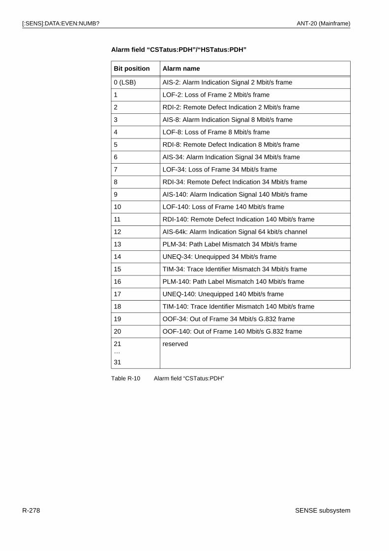
[:SENS]:DATA:EVEN:NUMB? ANT-20 (Mainframe)
Alarm field “CSTatus:PDH”/“HSTatus:PDH”
Bit position Alarm name
0 (LSB) AIS-2: Alarm Indication Signal 2 Mbit/s frame
1 LOF-2: Loss of Frame 2 Mbit/s frame
2 RDI-2: Remote Defect Indication 2 Mbit/s frame
3 AIS-8: Alarm Indication Signal 8 Mbit/s frame
4 LOF-8: Loss of Frame 8 Mbit/s frame
5 RDI-8: Remote Defect Indication 8 Mbit/s frame
6 AIS-34: Alarm Indication Signal 34 Mbit/s frame
7 LOF-34: Loss of Frame 34 Mbit/s frame
8 RDI-34: Remote Defect Indication 34 Mbit/s frame
9 AIS-140: Alarm Indication Signal 140 Mbit/s frame
10 LOF-140: Loss of Frame 140 Mbit/s frame
11 RDI-140: Remote Defect Indication 140 Mbit/s frame
12 AIS-64k: Alarm Indication Signal 64 kbit/s channel
13 PLM-34: Path Label Mismatch 34 Mbit/s frame
14 UNEQ-34: Unequipped 34 Mbit/s frame
15 TIM-34: Trace Identifier Mismatch 34 Mbit/s frame
16 PLM-140: Path Label Mismatch 140 Mbit/s frame
17 UNEQ-140: Unequipped 140 Mbit/s frame
18 TIM-140: Trace Identifier Mismatch 140 Mbit/s frame
19 OOF-34: Out of Frame 34 Mbit/s G.832 frame
20 OOF-140: Out of Frame 140 Mbit/s G.832 frame
21…
31
reserved
Table R-10 Alarm field “CSTatus:PDH”
R-278 SENSE subsystem
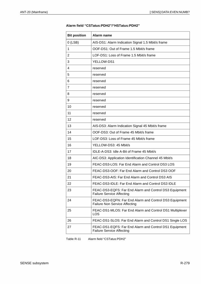
ANT-20 (Mainframe) [:SENS]:DATA:EVEN:NUMB?
Alarm field “CSTatus:PDH2”/“HSTatus:PDH2”
Bit position Alarm name
0 (LSB) AIS-DS1: Alarm Indication Signal 1.5 Mbit/s frame
1 OOF-DS1: Out of Frame 1.5 Mbit/s frame
2 LOF-DS1: Loss of Frame 1.5 Mbit/s frame
3 YELLOW-DS1
4 reserved
5 reserved
6 reserved
7 reserved
8 reserved
9 reserved
10 reserved
11 reserved
12 reserved
13 AIS-DS3: Alarm Indication Signal 45 Mbit/s frame
14 OOF-DS3: Out of Frame 45 Mbit/s frame
15 LOF-DS3: Loss of Frame 45 Mbit/s frame
16 YELLOW-DS3: 45 Mbit/s
17 IDLE-A-DS3: Idle A-Bit of Frame 45 Mbit/s
18 AIC-DS3: Application Identification Channel 45 Mbit/s
19 FEAC-DS3-LOS: Far End Alarm and Control DS3 LOS
20 FEAC-DS3-OOF: Far End Alarm and Control DS3 OOF
21 FEAC-DS3-AIS: Far End Alarm and Control DS3 AIS
22 FEAC-DS3-IDLE: Far End Alarm and Control DS3 IDLE
23 FEAC-DS3-EQFS: Far End Alarm and Control DS3 Equipment Failure Service Affecting
24 FEAC-DS3-EQFN: Far End Alarm and Control DS3 Equipment Failure Non Service Affecting
25 FEAC-DS1-MLOS: Far End Alarm and Control DS1 Multiplexer LOS
26 FEAC-DS1-SLOS: Far End Alarm and Control DS1 Single LOS
27 FEAC-DS1-EQFS: Far End Alarm and Control DS1 Equipment Failure Service Affecting
Table R-11 Alarm field “CSTatus:PDH2”
SENSE subsystem R-279
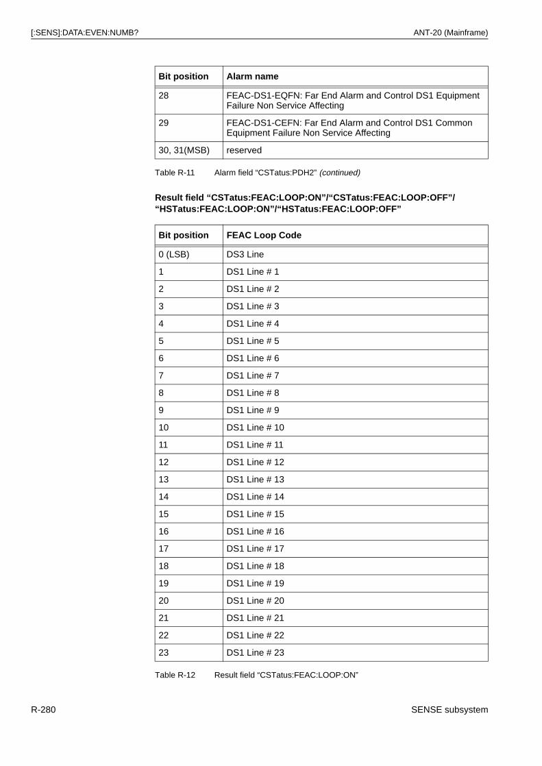
[:SENS]:DATA:EVEN:NUMB? ANT-20 (Mainframe)
Result field “CSTatus:FEAC:LOOP:ON”/“CSTatus:FEAC:LOOP:OFF”/“HSTatus:FEAC:LOOP:ON”/“HSTatus:FEAC:LOOP:OFF”
28 FEAC-DS1-EQFN: Far End Alarm and Control DS1 Equipment Failure Non Service Affecting
29 FEAC-DS1-CEFN: Far End Alarm and Control DS1 Common Equipment Failure Non Service Affecting
30, 31(MSB) reserved
Bit position FEAC Loop Code
0 (LSB) DS3 Line
1 DS1 Line # 1
2 DS1 Line # 2
3 DS1 Line # 3
4 DS1 Line # 4
5 DS1 Line # 5
6 DS1 Line # 6
7 DS1 Line # 7
8 DS1 Line # 8
9 DS1 Line # 9
10 DS1 Line # 10
11 DS1 Line # 11
12 DS1 Line # 12
13 DS1 Line # 13
14 DS1 Line # 14
15 DS1 Line # 15
16 DS1 Line # 16
17 DS1 Line # 17
18 DS1 Line # 18
19 DS1 Line # 19
20 DS1 Line # 20
21 DS1 Line # 21
22 DS1 Line # 22
23 DS1 Line # 23
Table R-12 Result field “CSTatus:FEAC:LOOP:ON”
Bit position Alarm name
Table R-11 Alarm field “CSTatus:PDH2” (continued)
R-280 SENSE subsystem
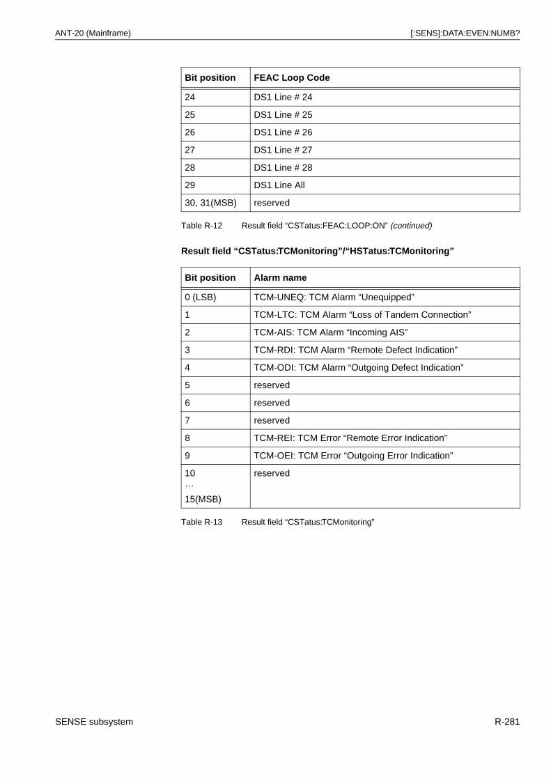
ANT-20 (Mainframe) [:SENS]:DATA:EVEN:NUMB?
Result field “CSTatus:TCMonitoring”/“HSTatus:TCMonitoring”
24 DS1 Line # 24
25 DS1 Line # 25
26 DS1 Line # 26
27 DS1 Line # 27
28 DS1 Line # 28
29 DS1 Line All
30, 31(MSB) reserved
Bit position Alarm name
0 (LSB) TCM-UNEQ: TCM Alarm “Unequipped”
1 TCM-LTC: TCM Alarm “Loss of Tandem Connection”
2 TCM-AIS: TCM Alarm “Incoming AIS”
3 TCM-RDI: TCM Alarm “Remote Defect Indication”
4 TCM-ODI: TCM Alarm “Outgoing Defect Indication”
5 reserved
6 reserved
7 reserved
8 TCM-REI: TCM Error “Remote Error Indication”
9 TCM-OEI: TCM Error “Outgoing Error Indication”
10…
15(MSB)
reserved
Table R-13 Result field “CSTatus:TCMonitoring”
Bit position FEAC Loop Code
Table R-12 Result field “CSTatus:FEAC:LOOP:ON” (continued)
SENSE subsystem R-281
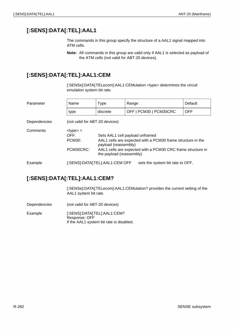
[:SENS]:DATA[:TEL]:AAL1 ANT-20 (Mainframe)
[:SENS]:DATA[:TEL]:AAL1
The commands in this group specify the structure of a AAL1 signal mapped into ATM cells.
Note: All commands in this group are valid only if AAL1 is selected as payload of the ATM cells (not valid for ABT-20 devices).
[:SENS]:DATA[:TEL]:AAL1:CEM
[:SENSe]:DATA[:TELecom]:AAL1:CEMulation <type> determines the circuit emulation system bit rate.
[:SENS]:DATA[:TEL]:AAL1:CEM?
[:SENSe]:DATA[:TELecom]:AAL1:CEMulation? provides the current setting of the AAL1 system bit rate.
Parameter Name Type Range Default
type discrete OFF | PCM30 | PCM30CRC OFF
Dependencies (not valid for ABT-20 devices)
Comments <type> =OFF: Sets AAL1 cell payload unframedPCM30: AAL1 cells are expected with a PCM30 frame structure in the
payload (reassembly)PCM30CRC: AAL1 cells are expected with a PCM30 CRC frame structure in
the payload (reassembly)
Example [:SENS]:DATA[:TEL]:AAL1:CEM OFF sets the system bit rate to OFF.
Dependencies (not valid for ABT-20 devices)
Example [:SENS]:DATA[:TEL]:AAL1:CEM?Response: OFFif the AAL1 system bit rate is disabled.
R-282 SENSE subsystem
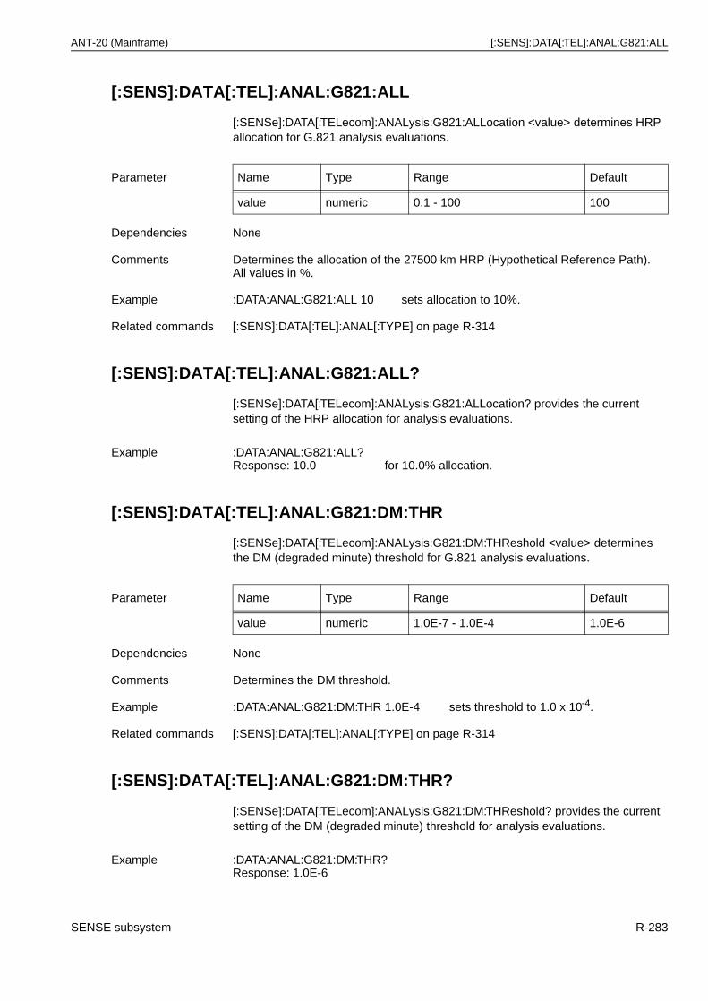
ANT-20 (Mainframe) [:SENS]:DATA[:TEL]:ANAL:G821:ALL
[:SENS]:DATA[:TEL]:ANAL:G821:ALL
[:SENSe]:DATA[:TELecom]:ANALysis:G821:ALLocation <value> determines HRP allocation for G.821 analysis evaluations.
[:SENS]:DATA[:TEL]:ANAL:G821:ALL?
[:SENSe]:DATA[:TELecom]:ANALysis:G821:ALLocation? provides the current setting of the HRP allocation for analysis evaluations.
[:SENS]:DATA[:TEL]:ANAL:G821:DM:THR
[:SENSe]:DATA[:TELecom]:ANALysis:G821:DM:THReshold <value> determines the DM (degraded minute) threshold for G.821 analysis evaluations.
[:SENS]:DATA[:TEL]:ANAL:G821:DM:THR?
[:SENSe]:DATA[:TELecom]:ANALysis:G821:DM:THReshold? provides the current setting of the DM (degraded minute) threshold for analysis evaluations.
Parameter Name Type Range Default
value numeric 0.1 - 100 100
Dependencies None
Comments Determines the allocation of the 27500 km HRP (Hypothetical Reference Path).All values in %.
Example :DATA:ANAL:G821:ALL 10 sets allocation to 10%.
Related commands [:SENS]:DATA[:TEL]:ANAL[:TYPE] on page R-314
Example :DATA:ANAL:G821:ALL?Response: 10.0 for 10.0% allocation.
Parameter Name Type Range Default
value numeric 1.0E-7 - 1.0E-4 1.0E-6
Dependencies None
Comments Determines the DM threshold.
Example :DATA:ANAL:G821:DM:THR 1.0E-4 sets threshold to 1.0 x 10⁻⁴.
Related commands [:SENS]:DATA[:TEL]:ANAL[:TYPE] on page R-314
Example :DATA:ANAL:G821:DM:THR?Response: 1.0E-6
SENSE subsystem R-283
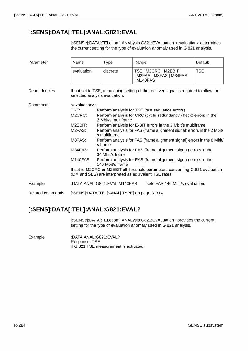
[:SENS]:DATA[:TEL]:ANAL:G821:EVAL ANT-20 (Mainframe)
[:SENS]:DATA[:TEL]:ANAL:G821:EVAL
[:SENSe]:DATA[:TELecom]:ANALysis:G821:EVALuation <evaluation> determines the current setting for the type of evaluation anomaly used in G.821 analysis.
[:SENS]:DATA[:TEL]:ANAL:G821:EVAL?
[:SENSe]:DATA[:TELecom]:ANALysis:G821:EVALuation? provides the current setting for the type of evaluation anomaly used in G.821 analysis.
Parameter Name Type Range Default
evaluation discrete TSE | M2CRC | M2EBIT| M2FAS | M8FAS | M34FAS| M140FAS
TSE
Dependencies If not set to TSE, a matching setting of the receiver signal is required to allow the selected analysis evaluation.
Comments <evaluation>:TSE: Perform analysis for TSE (test sequence errors)M2CRC: Perform analysis for CRC (cyclic redundancy check) errors in the
2 Mbit/s multiframeM2EBIT: Perform analysis for E-BIT errors in the 2 Mbit/s multiframeM2FAS: Perform analysis for FAS (frame alignment signal) errors in the 2 Mbit/
s multiframeM8FAS: Perform analysis for FAS (frame alignment signal) errors in the 8 Mbit/
s frameM34FAS: Perform analysis for FAS (frame alignment signal) errors in the
34 Mbit/s frameM140FAS: Perform analysis for FAS (frame alignment signal) errors in the
140 Mbit/s frameIf set to M2CRC or M2EBIT all threshold parameters concerning G.821 evaluation (DM and SES) are interpreted as equivalent TSE rates.
Example :DATA:ANAL:G821:EVAL M140FAS sets FAS 140 Mbit/s evaluation.
Related commands [:SENS]:DATA[:TEL]:ANAL[:TYPE] on page R-314
Example :DATA:ANAL:G821:EVAL?Response: TSEif G.821 TSE measurement is activated.
R-284 SENSE subsystem
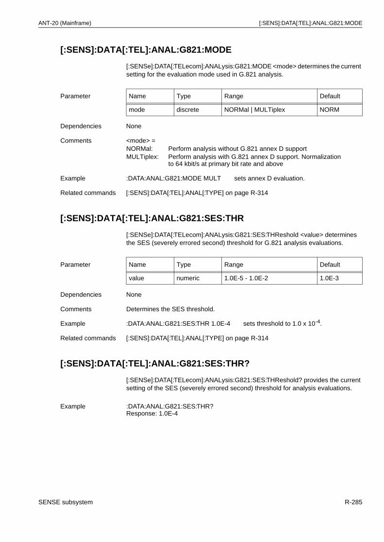
ANT-20 (Mainframe) [:SENS]:DATA[:TEL]:ANAL:G821:MODE
[:SENS]:DATA[:TEL]:ANAL:G821:MODE
[:SENSe]:DATA[:TELecom]:ANALysis:G821:MODE <mode> determines the current setting for the evaluation mode used in G.821 analysis.
[:SENS]:DATA[:TEL]:ANAL:G821:SES:THR
[:SENSe]:DATA[:TELecom]:ANALysis:G821:SES:THReshold <value> determines the SES (severely errored second) threshold for G.821 analysis evaluations.
[:SENS]:DATA[:TEL]:ANAL:G821:SES:THR?
[:SENSe]:DATA[:TELecom]:ANALysis:G821:SES:THReshold? provides the current setting of the SES (severely errored second) threshold for analysis evaluations.
Parameter Name Type Range Default
mode discrete NORMal | MULTiplex NORM
Dependencies None
Comments <mode> =NORMal: Perform analysis without G.821 annex D supportMULTiplex: Perform analysis with G.821 annex D support. Normalization
to 64 kbit/s at primary bit rate and above
Example :DATA:ANAL:G821:MODE MULT sets annex D evaluation.
Related commands [:SENS]:DATA[:TEL]:ANAL[:TYPE] on page R-314
Parameter Name Type Range Default
value numeric 1.0E-5 - 1.0E-2 1.0E-3
Dependencies None
Comments Determines the SES threshold.
Example :DATA:ANAL:G821:SES:THR 1.0E-4 sets threshold to 1.0 x 10⁻⁴.
Related commands [:SENS]:DATA[:TEL]:ANAL[:TYPE] on page R-314
Example :DATA:ANAL:G821:SES:THR?Response: 1.0E-4
SENSE subsystem R-285
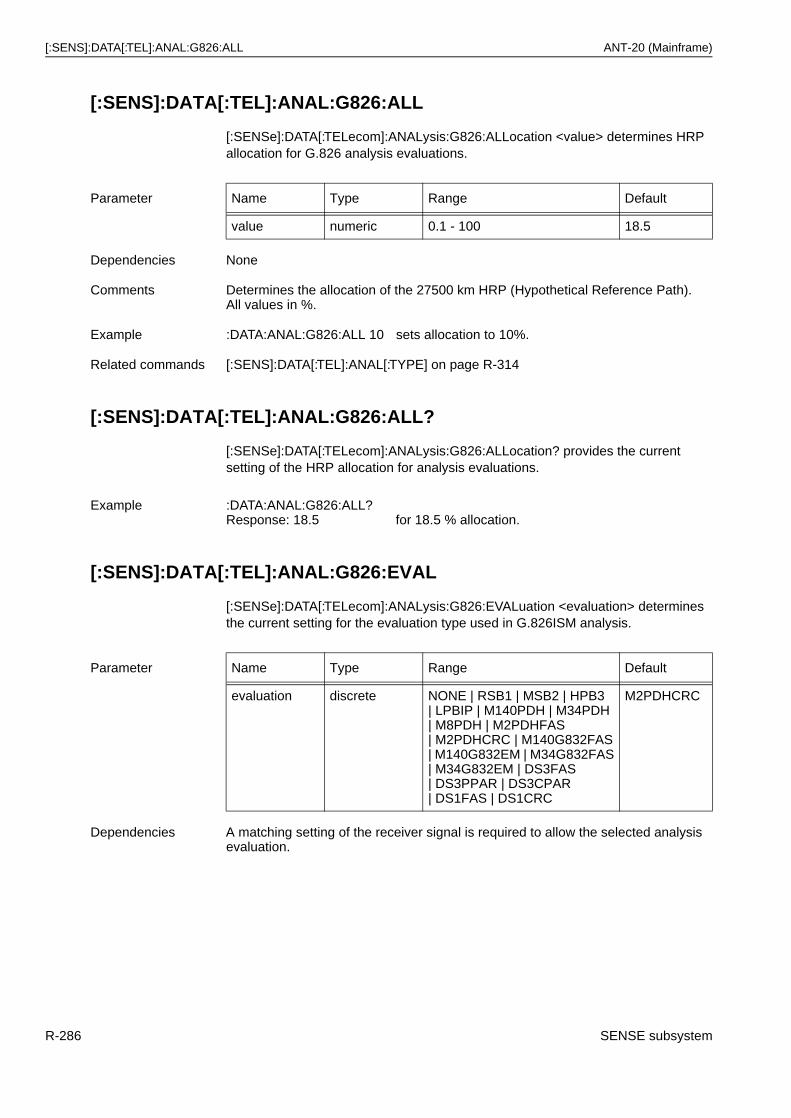
[:SENS]:DATA[:TEL]:ANAL:G826:ALL ANT-20 (Mainframe)
[:SENS]:DATA[:TEL]:ANAL:G826:ALL
[:SENSe]:DATA[:TELecom]:ANALysis:G826:ALLocation <value> determines HRP allocation for G.826 analysis evaluations.
[:SENS]:DATA[:TEL]:ANAL:G826:ALL?
[:SENSe]:DATA[:TELecom]:ANALysis:G826:ALLocation? provides the current setting of the HRP allocation for analysis evaluations.
[:SENS]:DATA[:TEL]:ANAL:G826:EVAL
[:SENSe]:DATA[:TELecom]:ANALysis:G826:EVALuation <evaluation> determines the current setting for the evaluation type used in G.826ISM analysis.
Parameter Name Type Range Default
value numeric 0.1 - 100 18.5
Dependencies None
Comments Determines the allocation of the 27500 km HRP (Hypothetical Reference Path).All values in %.
Example :DATA:ANAL:G826:ALL 10 sets allocation to 10%.
Related commands [:SENS]:DATA[:TEL]:ANAL[:TYPE] on page R-314
Example :DATA:ANAL:G826:ALL?Response: 18.5 for 18.5 % allocation.
Parameter Name Type Range Default
evaluation discrete NONE | RSB1 | MSB2 | HPB3| LPBIP | M140PDH | M34PDH| M8PDH | M2PDHFAS| M2PDHCRC | M140G832FAS| M140G832EM | M34G832FAS| M34G832EM | DS3FAS| DS3PPAR | DS3CPAR| DS1FAS | DS1CRC
M2PDHCRC
Dependencies A matching setting of the receiver signal is required to allow the selected analysis evaluation.
R-286 SENSE subsystem
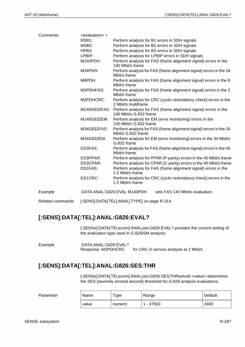
ANT-20 (Mainframe) [:SENS]:DATA[:TEL]:ANAL:G826:EVAL?
[:SENS]:DATA[:TEL]:ANAL:G826:EVAL?
[:SENSe]:DATA[:TELecom]:ANALysis:G826:EVAL? provides the current setting of the evaluation type used in G.826ISM analysis.
[:SENS]:DATA[:TEL]:ANAL:G826:SES:THR
[:SENSe]:DATA[:TELecom]:ANALysis:G826:SES:THReshold <value> determines the SES (severely errored second) threshold for G.826 analysis evaluations.
Comments <evaluation> =RSB1: Perform analysis for B1 errors in SDH signalsMSB2: Perform analysis for B2 errors in SDH signalsHPB3: Perform analysis for B3 errors in SDH signalsLPBIP: Perform analysis for LPBIP errors in SDH signalsM140PDH: Perform analysis for FAS (frame alignment signal) errors in the
140 Mbit/s frameM34PDH: Perform analysis for FAS (frame alignment signal) errors in the 34
Mbit/s frameM8PDH: Perform analysis for FAS (frame alignment signal) errors in the 8
Mbit/s frameM2PDHFAS: Perform analysis for FAS (frame alignment signal) errors in the 2
Mbit/s frameM2PDHCRC: Perform analysis for CRC (cyclic redundancy check) errors in the
2 Mbit/s multiframeM140G832FAS: Perform analysis for FAS (frame alignment signal) errors in the
140 Mbit/s G.832 frameM140G832EM: Perform analysis for EM (error monitoring) errors in the
140 Mbit/s G.832 frameM34G832FAS: Perform analysis for FAS (frame alignment signal) errors in the 34
Mbit/s G.832 frameM34G832EM: Perform analysis for EM (error monitoring) errors in the 34 Mbit/s
G.832 frameDS3FAS: Perform analysis for FAS (frame alignment signal) errors in the 45
Mbit/s frameDS3PPAR: Perform analysis for PPAR (P-parity) errors in the 45 Mbit/s frameDS3CPAR: Perform analysis for CPAR (C-parity) errors in the 45 Mbit/s frameDS1FAS: Perform analysis for FAS (frame alignment signal) errors in the
1.5 Mbit/s frameDS1CRC: Perform analysis for CRC (cyclic redundancy check) errors in the
1.5 Mbit/s frame
Example :DATA:ANAL:G826:EVAL M140PDH sets FAS 140 Mbit/s evaluation.
Related commands [:SENS]:DATA[:TEL]:ANAL[:TYPE] on page R-314
Example :DATA:ANAL:G826:EVAL?Response: M2PDHCRC for CRC in service analysis at 2 Mbit/s.
Parameter Name Type Range Default
value numeric 1 - 47563 2400
SENSE subsystem R-287
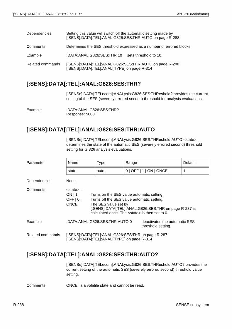
[:SENS]:DATA[:TEL]:ANAL:G826:SES:THR? ANT-20 (Mainframe)
[:SENS]:DATA[:TEL]:ANAL:G826:SES:THR?
[:SENSe]:DATA[:TELecom]:ANALysis:G826:SES:THReshold? provides the current setting of the SES (severely errored second) threshold for analysis evaluations.
[:SENS]:DATA[:TEL]:ANAL:G826:SES:THR:AUTO
[:SENSe]:DATA[:TELecom]:ANALysis:G826:SES:THReshold:AUTO <state> determines the state of the automatic SES (severely errored second) threshold setting for G.826 analysis evaluations.
[:SENS]:DATA[:TEL]:ANAL:G826:SES:THR:AUTO?
[:SENSe]:DATA[:TELecom]:ANALysis:G826:SES:THReshold:AUTO? provides the current setting of the automatic SES (severely errored second) threshold value setting.
Dependencies Setting this value will switch off the automatic setting made by [:SENS]:DATA[:TEL]:ANAL:G826:SES:THR:AUTO on page R-288.
Comments Determines the SES threshold expressed as a number of errored blocks.
Example :DATA:ANAL:G826:SES:THR 10 sets threshold to 10.
Related commands [:SENS]:DATA[:TEL]:ANAL:G826:SES:THR:AUTO on page R-288[:SENS]:DATA[:TEL]:ANAL[:TYPE] on page R-314
Example :DATA:ANAL:G826:SES:THR?Response: 5000
Parameter Name Type Range Default
state auto 0 | OFF | 1 | ON | ONCE 1
Dependencies None
Comments <state> =ON | 1: Turns on the SES value automatic setting.OFF | 0: Turns off the SES value automatic setting.ONCE: The SES value set by
[:SENS]:DATA[:TEL]:ANAL:G826:SES:THR on page R-287 iscalculated once. The <state> is then set to 0.
Example :DATA:ANAL:G826:SES:THR:AUTO 0 deactivates the automatic SES threshold setting.
Related commands [:SENS]:DATA[:TEL]:ANAL:G826:SES:THR on page R-287[:SENS]:DATA[:TEL]:ANAL[:TYPE] on page R-314
Comments ONCE: is a volatile state and cannot be read.
R-288 SENSE subsystem
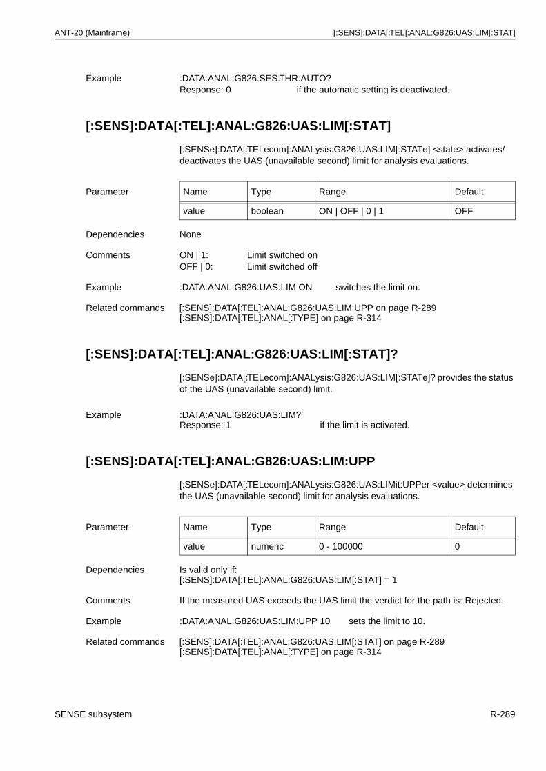
ANT-20 (Mainframe) [:SENS]:DATA[:TEL]:ANAL:G826:UAS:LIM[:STAT]
[:SENS]:DATA[:TEL]:ANAL:G826:UAS:LIM[:STAT]
[:SENSe]:DATA[:TELecom]:ANALysis:G826:UAS:LIM[:STATe] <state> activates/deactivates the UAS (unavailable second) limit for analysis evaluations.
[:SENS]:DATA[:TEL]:ANAL:G826:UAS:LIM[:STAT]?
[:SENSe]:DATA[:TELecom]:ANALysis:G826:UAS:LIM[:STATe]? provides the status of the UAS (unavailable second) limit.
[:SENS]:DATA[:TEL]:ANAL:G826:UAS:LIM:UPP
[:SENSe]:DATA[:TELecom]:ANALysis:G826:UAS:LIMit:UPPer <value> determines the UAS (unavailable second) limit for analysis evaluations.
Example :DATA:ANAL:G826:SES:THR:AUTO?Response: 0 if the automatic setting is deactivated.
Parameter Name Type Range Default
value boolean ON | OFF | 0 | 1 OFF
Dependencies None
Comments ON | 1: Limit switched onOFF | 0: Limit switched off
Example :DATA:ANAL:G826:UAS:LIM ON switches the limit on.
Related commands [:SENS]:DATA[:TEL]:ANAL:G826:UAS:LIM:UPP on page R-289[:SENS]:DATA[:TEL]:ANAL[:TYPE] on page R-314
Example :DATA:ANAL:G826:UAS:LIM?Response: 1 if the limit is activated.
Parameter Name Type Range Default
value numeric 0 - 100000 0
Dependencies Is valid only if:[:SENS]:DATA[:TEL]:ANAL:G826:UAS:LIM[:STAT] = 1
Comments If the measured UAS exceeds the UAS limit the verdict for the path is: Rejected.
Example :DATA:ANAL:G826:UAS:LIM:UPP 10 sets the limit to 10.
Related commands [:SENS]:DATA[:TEL]:ANAL:G826:UAS:LIM[:STAT] on page R-289[:SENS]:DATA[:TEL]:ANAL[:TYPE] on page R-314
SENSE subsystem R-289
[:SENS]:DATA[:TEL]:ANAL:G826:UAS:LIM:UPP? ANT-20 (Mainframe)
[:SENS]:DATA[:TEL]:ANAL:G826:UAS:LIM:UPP?
[:SENSe]:DATA[:TELecom]:ANALysis:G826:UAS:LIMit:UPPer? provides the current setting of the UAS (unavailable second) limit for analysis evaluations.
[:SENS]:DATA[:TEL]:ANAL:G826:UAS:MODE
[:SENSe]:DATA[:TELecom]:ANALysis:G826:UAS:MODE <mode> determines the current setting for the UAS (unavailable seconds) evaluation mode used in G.826ISM analysis.
[:SENS]:DATA[:TEL]:ANAL:G826:UAS:MODE?
[:SENSe]:DATA[:TELecom]:ANALysis:G826:UAS:MODE? provides the status of the UAS (unavailable seconds) evaluation mode used in G.826ISM analysis.
Example :DATA:ANAL:G826:UAS:LIM:UPP?Response: 5000
Parameter Name Type Range Default
mode discrete INDividual | GLOBal INDividual
Dependencies Only selectable if near end and far end are evaluated.
Comments <mode> =INDividual: Individual evaluation of UAS for near end and far endGLOBal: Global evaluation of UAS for near end and far end
Example :DATA:ANAL:G826:UAS:MODE GLOB sets the UAS evaluation to global.
Related commands [:SENS]:DATA[:TEL]:ANAL[:TYPE] on page R-314
Example :DATA:ANAL:G826:UAS:MODE?Response: INDI for individual UAS evaluation mode.
R-290 SENSE subsystem
ANT-20 (Mainframe) [:SENS]:DATA[:TEL]:ANAL:G828:ALL
[:SENS]:DATA[:TEL]:ANAL:G828:ALL
[:SENSe]:DATA[:TELecom]:ANALysis:G828:ALLocation <value> determines the allocation for G.828 analysis evaluations.
[:SENS]:DATA[:TEL]:ANAL:G828:ALL?
[:SENSe]:DATA[:TELecom]:ANALysis:G828:ALLocation? provides the current setting of the allocation for analysis evaluations.
[:SENS]:DATA[:TEL]:ANAL:G828:EVAL
[:SENSe]:DATA[:TELecom]:ANALysis:G828:EVALuation <evaluation> determines the current setting of the anomaly evaluation type used in G.828 analysis.
Parameter Name Type Range Default
value numeric 0.1 - 100 18.5
Dependencies None
Comments Determines the allocation of the 27500 km HRP (Hypothetical Reference Path).All values in %.
Example :DATA:ANAL:G828:ALL 10 sets the allocation to 10%.
Related commands [:SENS]:DATA[:TEL]:ANAL[:TYPE] on page R-314
Example :DATA:ANAL:G828:ALL?Response: 10.0 for 10.0 % allocation.
Parameter Name Type Range Default
evaluation discrete NONE | RSB1 | MSB2 | HPB3| LPBIP | TCM | TSE
HPB3
Dependencies If not set to TSE, a matching setting of the receiver signal is required to allow the selected analysis evaluation.
Comments <evaluation> =NONE: No G.828 analysisRSB1: Perform analysis for B1 errors in SDH signalsMSB2: Perform analysis for B2 errors in SDH signalsHPB3: Perform analysis for B3 errors in SDH signalsLPBIP: Perform analysis for LPBIP errors in SDH signalsTCM: Perform analysis for TCM (Tandem Connection Monitoring) Bytes
N1/N2 (Z6)Not yet available!
TSE: Perform analysis for TSE (test sequence errors)
Example :DATA:ANAL:G828:EVAL HPB3 sets high path B3 error evaluation.
SENSE subsystem R-291
[:SENS]:DATA[:TEL]:ANAL:G828:EVAL? ANT-20 (Mainframe)
[:SENS]:DATA[:TEL]:ANAL:G828:EVAL?
[:SENSe]:DATA[:TELecom]:ANALysis:G828:EVALuation? provides the current setting of the anomaly evaluation type used in G.828 analysis.
[:SENS]:DATA[:TEL]:ANAL:G828:SEPI[:STAT]
[:SENSe]:DATA[:TELecom]:ANALysis:G828:SEPIntensity[:STATe] <state> activates/deactivates the consideration of SEPI (Severely Errored Period Intensity) in the calculation of the verdict.
[:SENS]:DATA[:TEL]:ANAL:G828:SEPI[:STAT]?
[:SENSe]:DATA[:TELecom]:ANALysis:G828:SEPIntensity[:STATe]? provides the status of the consideration of SEPI (Severely Errored Period Intensity) in the calculation of the verdict.
[:SENS]:DATA[:TEL]:ANAL:G828:SES:THR
[:SENSe]:DATA[:TELecom]:ANALysis:G828:SES:THReshold <value> determines the SES (severely errored second) threshold for G.828 analysis evaluations.
Related commands [:SENS]:DATA[:TEL]:ANAL[:TYPE] on page R-314
Example :DATA:ANAL:G828:EVAL?Response: HPB3 if G.828 HPB3 measurement is activated.
Parameter Name Type Range Default
state boolean ON | OFF | 0 | 1 OFF
Dependencies None
Comments ON | 1: Consideration switched onOFF | 0: Consideration switched off
Example :DATA:ANAL:G828:SEPI ON switches the consideration on.
Example :DATA:ANAL:G828:SEPI?Response: 1 if the consideration is activated.
Parameter Name Type Range Default
value numeric 1 - 8000 2400
Dependencies Setting this value will switch off the automatic setting made by[:SENS]:DATA[:TEL]:ANAL:G828:SES:THR:AUTO on page R-293
R-292 SENSE subsystem
ANT-20 (Mainframe) [:SENS]:DATA[:TEL]:ANAL:G828:SES:THR?
[:SENS]:DATA[:TEL]:ANAL:G828:SES:THR?
[:SENSe]:DATA[:TELecom]:ANALysis:G828:SES:THReshold? provides the current setting of the SES (severely errored second) threshold for analysis evaluations.
[:SENS]:DATA[:TEL]:ANAL:G828:SES:THR:AUTO
[:SENSe]:DATA[:TELecom]:ANALysis:G828:SES:THReshold:AUTO <state> determines the state of the automatic SES (severely errored second) threshold setting for G.828 analysis evaluations.
[:SENS]:DATA[:TEL]:ANAL:G828:SES:THR:AUTO?
[:SENSe]:DATA[:TELecom]:ANALysis:G828:SES:THReshold:AUTO? provides the current setting of the automatic SES (severely errored second) threshold value setting.
Comments Determines the SES threshold expressed as a number of errored blocks.
Example :DATA:ANAL:G828:SES:THR 10 sets threshold to 10.
Related commands [:SENS]:DATA[:TEL]:ANAL:G828:SES:THR:AUTO on page R-293[:SENS]:DATA[:TEL]:ANAL[:TYPE] on page R-314
Example :DATA:ANAL:G828:SES:THR?Response: 5000
Parameter Name Type Range Default
state auto 0 | OFF | 1 | ON | ONCE 1
Dependencies None
Comments <state> =ON | 1: Turns on the SES value automatic setting.OFF | 0: Turns off the SES value automatic setting.ONCE: The SES value set by
[:SENS]:DATA[:TEL]:ANAL:G828:SES:THR on page R-292 iscalculated once. The <state> is then set to 0.
Example :DATA:ANAL:G828:SES:THR:AUTO 0 deactivates the automatic SES threshold setting.
Related commands [:SENS]:DATA[:TEL]:ANAL:G828:SES:THR on page R-292[:SENS]:DATA[:TEL]:ANAL[:TYPE] on page R-314
Comments ONCE: is a volatile state and cannot be read.
Example :DATA:ANAL:G828:SES:THR:AUTO?Response: 0 if the automatic setting is deactivated.
SENSE subsystem R-293

[:SENS]:DATA[:TEL]:ANAL:G828:UAS:LIM[:STAT] ANT-20 (Mainframe)
[:SENS]:DATA[:TEL]:ANAL:G828:UAS:LIM[:STAT]
[:SENSe]:DATA[:TELecom]:ANALysis:G828:UAS:LIM[:STATe] <state> activates/deactivates the UAS (unavailable second) limit for analysis evaluations.
[:SENS]:DATA[:TEL]:ANAL:G828:UAS:LIM[:STAT]?
[:SENSe]:DATA[:TELecom]:ANALysis:G828:UAS:LIM[:STATe]? provides the status of the UAS (unavailable second) limit.
[:SENS]:DATA[:TEL]:ANAL:G828:UAS:LIM:UPP
[:SENSe]:DATA[:TELecom]:ANALysis:G828:UAS:LIMit:UPPer <value> determines the UAS (unavailable second) limit for analysis evaluations.
[:SENS]:DATA[:TEL]:ANAL:G828:UAS:LIM:UPP?
[:SENSe]:DATA[:TELecom]:ANALysis:G828:UAS:LIMit:UPPer? provides the current setting of the UAS (unavailable second) limit for analysis evaluations.
Parameter Name Type Range Default
value boolean ON | OFF | 0 | 1 OFF
Dependencies None
Comments ON | 1: Limit switched onOFF | 0: Limit switched off
Example :DATA:ANAL:G828:UAS:LIM ON switches the limit on.
Related commands [:SENS]:DATA[:TEL]:ANAL:G828:UAS:LIM:UPP on page R-294[:SENS]:DATA[:TEL]:ANAL[:TYPE] on page R-314
Example :DATA:ANAL:G828:UAS:LIM?Response: 1 if the limit is activated.
Parameter Name Type Range Default
value numeric 0 - 100000 0
Dependencies Is valid only if:[:SENS]:DATA[:TEL]:ANAL:G828:UAS:LIM[:STAT] = 1
Comments If the measured UAS exceeds the UAS limit the verdict for the path is: Rejected.
Example :DATA:ANAL:G828:UAS:LIM:UPP 10 sets the limit to 10.
Related commands [:SENS]:DATA[:TEL]:ANAL:G828:UAS:LIM[:STAT] on page R-294[:SENS]:DATA[:TEL]:ANAL[:TYPE] on page R-314
R-294 SENSE subsystem
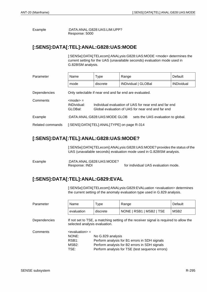
ANT-20 (Mainframe) [:SENS]:DATA[:TEL]:ANAL:G828:UAS:MODE
[:SENS]:DATA[:TEL]:ANAL:G828:UAS:MODE
[:SENSe]:DATA[:TELecom]:ANALysis:G828:UAS:MODE <mode> determines the current setting for the UAS (unavailable seconds) evaluation mode used in G.828ISM analysis.
[:SENS]:DATA[:TEL]:ANAL:G828:UAS:MODE?
[:SENSe]:DATA[:TELecom]:ANALysis:G828:UAS:MODE? provides the status of the UAS (unavailable seconds) evaluation mode used in G.828ISM analysis.
[:SENS]:DATA[:TEL]:ANAL:G829:EVAL
[:SENSe]:DATA[:TELecom]:ANALysis:G829:EVALuation <evaluation> determines the current setting of the anomaly evaluation type used in G.829 analysis.
Example :DATA:ANAL:G828:UAS:LIM:UPP?Response: 5000
Parameter Name Type Range Default
mode discrete INDividual | GLOBal INDividual
Dependencies Only selectable if near end and far end are evaluated.
Comments <mode> =INDividual: Individual evaluation of UAS for near end and far endGLOBal: Global evaluation of UAS for near end and far end
Example :DATA:ANAL:G828:UAS:MODE GLOB sets the UAS evaluation to global.
Related commands [:SENS]:DATA[:TEL]:ANAL[:TYPE] on page R-314
Example :DATA:ANAL:G828:UAS:MODE?Response: INDI for individual UAS evaluation mode.
Parameter Name Type Range Default
evaluation discrete NONE | RSB1 | MSB2 | TSE MSB2
Dependencies If not set to TSE, a matching setting of the receiver signal is required to allow the selected analysis evaluation.
Comments <evaluation> =NONE: No G.829 analysisRSB1: Perform analysis for B1 errors in SDH signalsMSB2: Perform analysis for B2 errors in SDH signalsTSE: Perform analysis for TSE (test sequence errors)
SENSE subsystem R-295
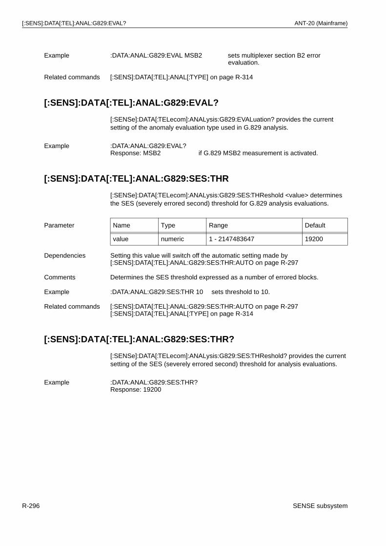
[:SENS]:DATA[:TEL]:ANAL:G829:EVAL? ANT-20 (Mainframe)
[:SENS]:DATA[:TEL]:ANAL:G829:EVAL?
[:SENSe]:DATA[:TELecom]:ANALysis:G829:EVALuation? provides the current setting of the anomaly evaluation type used in G.829 analysis.
[:SENS]:DATA[:TEL]:ANAL:G829:SES:THR
[:SENSe]:DATA[:TELecom]:ANALysis:G829:SES:THReshold <value> determines the SES (severely errored second) threshold for G.829 analysis evaluations.
[:SENS]:DATA[:TEL]:ANAL:G829:SES:THR?
[:SENSe]:DATA[:TELecom]:ANALysis:G829:SES:THReshold? provides the current setting of the SES (severely errored second) threshold for analysis evaluations.
Example :DATA:ANAL:G829:EVAL MSB2 sets multiplexer section B2 error evaluation.
Related commands [:SENS]:DATA[:TEL]:ANAL[:TYPE] on page R-314
Example :DATA:ANAL:G829:EVAL?Response: MSB2 if G.829 MSB2 measurement is activated.
Parameter Name Type Range Default
value numeric 1 - 2147483647 19200
Dependencies Setting this value will switch off the automatic setting made by[:SENS]:DATA[:TEL]:ANAL:G829:SES:THR:AUTO on page R-297
Comments Determines the SES threshold expressed as a number of errored blocks.
Example :DATA:ANAL:G829:SES:THR 10 sets threshold to 10.
Related commands [:SENS]:DATA[:TEL]:ANAL:G829:SES:THR:AUTO on page R-297[:SENS]:DATA[:TEL]:ANAL[:TYPE] on page R-314
Example :DATA:ANAL:G829:SES:THR?Response: 19200
R-296 SENSE subsystem
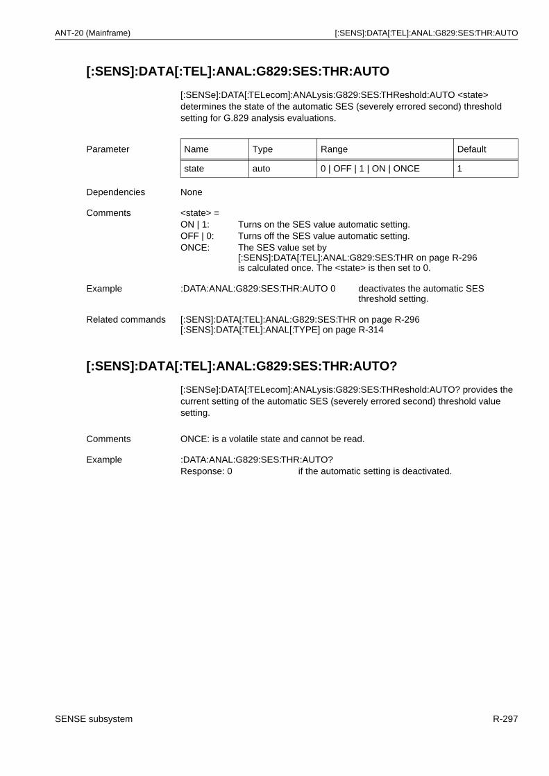
ANT-20 (Mainframe) [:SENS]:DATA[:TEL]:ANAL:G829:SES:THR:AUTO
[:SENS]:DATA[:TEL]:ANAL:G829:SES:THR:AUTO
[:SENSe]:DATA[:TELecom]:ANALysis:G829:SES:THReshold:AUTO <state> determines the state of the automatic SES (severely errored second) threshold setting for G.829 analysis evaluations.
[:SENS]:DATA[:TEL]:ANAL:G829:SES:THR:AUTO?
[:SENSe]:DATA[:TELecom]:ANALysis:G829:SES:THReshold:AUTO? provides the current setting of the automatic SES (severely errored second) threshold value setting.
Parameter Name Type Range Default
state auto 0 | OFF | 1 | ON | ONCE 1
Dependencies None
Comments <state> =ON | 1: Turns on the SES value automatic setting.OFF | 0: Turns off the SES value automatic setting.ONCE: The SES value set by
[:SENS]:DATA[:TEL]:ANAL:G829:SES:THR on page R-296is calculated once. The <state> is then set to 0.
Example :DATA:ANAL:G829:SES:THR:AUTO 0 deactivates the automatic SES threshold setting.
Related commands [:SENS]:DATA[:TEL]:ANAL:G829:SES:THR on page R-296[:SENS]:DATA[:TEL]:ANAL[:TYPE] on page R-314
Comments ONCE: is a volatile state and cannot be read.
Example :DATA:ANAL:G829:SES:THR:AUTO?Response: 0 if the automatic setting is deactivated.
SENSE subsystem R-297
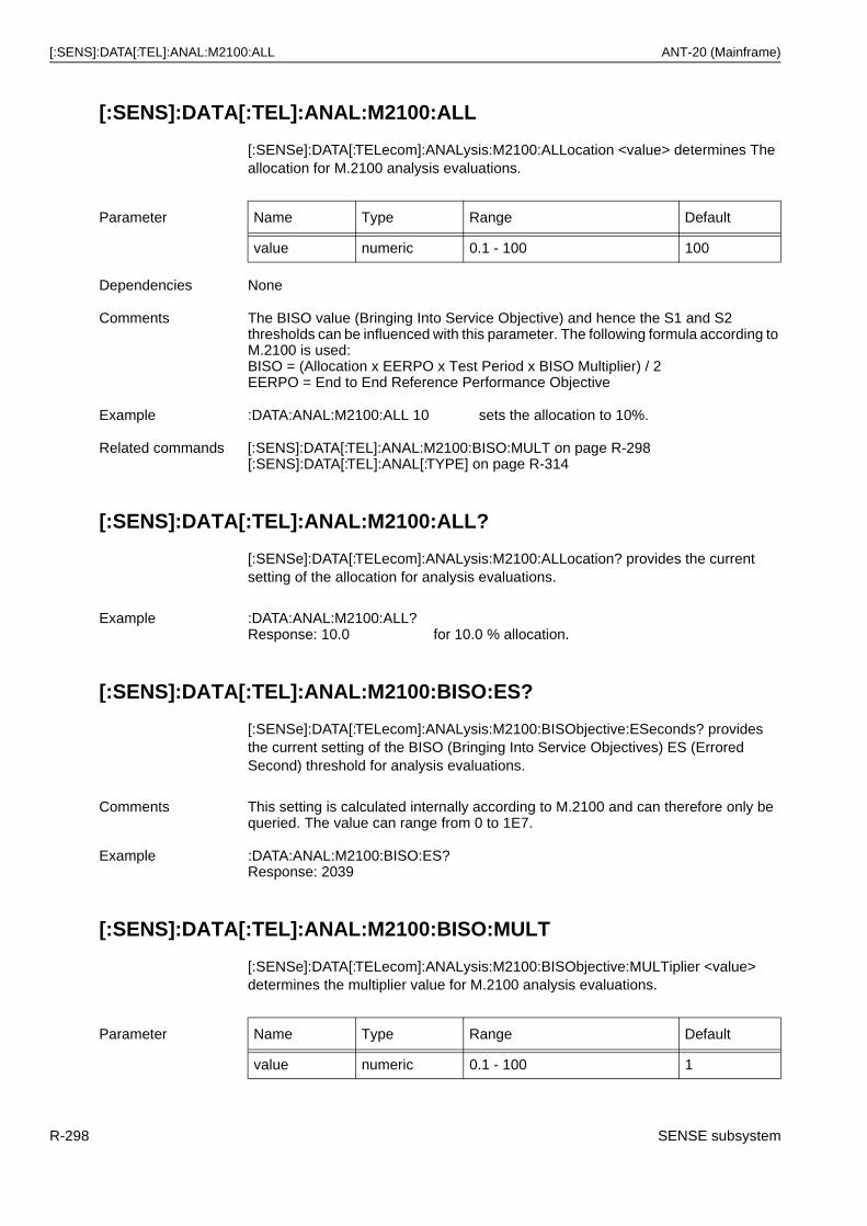
[:SENS]:DATA[:TEL]:ANAL:M2100:ALL ANT-20 (Mainframe)
[:SENS]:DATA[:TEL]:ANAL:M2100:ALL
[:SENSe]:DATA[:TELecom]:ANALysis:M2100:ALLocation <value> determines The allocation for M.2100 analysis evaluations.
[:SENS]:DATA[:TEL]:ANAL:M2100:ALL?
[:SENSe]:DATA[:TELecom]:ANALysis:M2100:ALLocation? provides the current setting of the allocation for analysis evaluations.
[:SENS]:DATA[:TEL]:ANAL:M2100:BISO:ES?
[:SENSe]:DATA[:TELecom]:ANALysis:M2100:BISObjective:ESeconds? provides the current setting of the BISO (Bringing Into Service Objectives) ES (Errored Second) threshold for analysis evaluations.
[:SENS]:DATA[:TEL]:ANAL:M2100:BISO:MULT
[:SENSe]:DATA[:TELecom]:ANALysis:M2100:BISObjective:MULTiplier <value> determines the multiplier value for M.2100 analysis evaluations.
Parameter Name Type Range Default
value numeric 0.1 - 100 100
Dependencies None
Comments The BISO value (Bringing Into Service Objective) and hence the S1 and S2 thresholds can be influenced with this parameter. The following formula according to M.2100 is used:BISO = (Allocation x EERPO x Test Period x BISO Multiplier) / 2EERPO = End to End Reference Performance Objective
Example :DATA:ANAL:M2100:ALL 10 sets the allocation to 10%.
Related commands [:SENS]:DATA[:TEL]:ANAL:M2100:BISO:MULT on page R-298[:SENS]:DATA[:TEL]:ANAL[:TYPE] on page R-314
Example :DATA:ANAL:M2100:ALL?Response: 10.0 for 10.0 % allocation.
Comments This setting is calculated internally according to M.2100 and can therefore only be queried. The value can range from 0 to 1E7.
Example :DATA:ANAL:M2100:BISO:ES?Response: 2039
Parameter Name Type Range Default
value numeric 0.1 - 100 1
R-298 SENSE subsystem
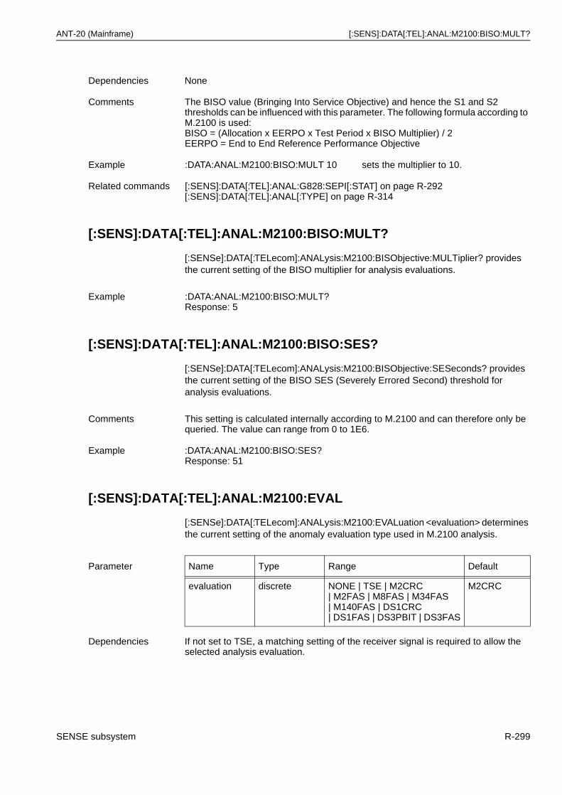
ANT-20 (Mainframe) [:SENS]:DATA[:TEL]:ANAL:M2100:BISO:MULT?
[:SENS]:DATA[:TEL]:ANAL:M2100:BISO:MULT?
[:SENSe]:DATA[:TELecom]:ANALysis:M2100:BISObjective:MULTiplier? provides the current setting of the BISO multiplier for analysis evaluations.
[:SENS]:DATA[:TEL]:ANAL:M2100:BISO:SES?
[:SENSe]:DATA[:TELecom]:ANALysis:M2100:BISObjective:SESeconds? provides the current setting of the BISO SES (Severely Errored Second) threshold for analysis evaluations.
[:SENS]:DATA[:TEL]:ANAL:M2100:EVAL
[:SENSe]:DATA[:TELecom]:ANALysis:M2100:EVALuation <evaluation> determines the current setting of the anomaly evaluation type used in M.2100 analysis.
Dependencies None
Comments The BISO value (Bringing Into Service Objective) and hence the S1 and S2 thresholds can be influenced with this parameter. The following formula according to M.2100 is used:BISO = (Allocation x EERPO x Test Period x BISO Multiplier) / 2EERPO = End to End Reference Performance Objective
Example :DATA:ANAL:M2100:BISO:MULT 10 sets the multiplier to 10.
Related commands [:SENS]:DATA[:TEL]:ANAL:G828:SEPI[:STAT] on page R-292[:SENS]:DATA[:TEL]:ANAL[:TYPE] on page R-314
Example :DATA:ANAL:M2100:BISO:MULT?Response: 5
Comments This setting is calculated internally according to M.2100 and can therefore only be queried. The value can range from 0 to 1E6.
Example :DATA:ANAL:M2100:BISO:SES?Response: 51
Parameter Name Type Range Default
evaluation discrete NONE | TSE | M2CRC| M2FAS | M8FAS | M34FAS| M140FAS | DS1CRC| DS1FAS | DS3PBIT | DS3FAS
M2CRC
Dependencies If not set to TSE, a matching setting of the receiver signal is required to allow the selected analysis evaluation.
SENSE subsystem R-299
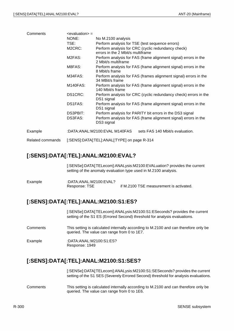
[:SENS]:DATA[:TEL]:ANAL:M2100:EVAL? ANT-20 (Mainframe)
[:SENS]:DATA[:TEL]:ANAL:M2100:EVAL?
[:SENSe]:DATA[:TELecom]:ANALysis:M2100:EVALuation? provides the current setting of the anomaly evaluation type used in M.2100 analysis.
[:SENS]:DATA[:TEL]:ANAL:M2100:S1:ES?
[:SENSe]:DATA[:TELecom]:ANALysis:M2100:S1:ESeconds? provides the current setting of the S1 ES (Errored Second) threshold for analysis evaluations.
[:SENS]:DATA[:TEL]:ANAL:M2100:S1:SES?
[:SENSe]:DATA[:TELecom]:ANALysis:M2100:S1:SESeconds? provides the current setting of the S1 SES (Severely Errored Second) threshold for analysis evaluations.
Comments <evaluation> =NONE: No M.2100 analysisTSE: Perform analysis for TSE (test sequence errors)M2CRC: Perform analysis for CRC (cyclic redundancy check)
errors in the 2 Mbit/s multiframeM2FAS: Perform analysis for FAS (frame alignment signal) errors in the
2 Mbit/s multiframeM8FAS: Perform analysis for FAS (frame alignment signal) errors in the
8 Mbit/s frameM34FAS: Perform analysis for FAS (frames alignment signal) errors in the
34 MBit/s frameM140FAS: Perform analysis for FAS (frame alignment signal) errors in the
140 Mbit/s frameDS1CRC: Perform analysis for CRC (cyclic redundancy check) errors in the
DS1 signalDS1FAS: Perform analysis for FAS (frame alignment signal) errors in the
DS1 signalDS3PBIT: Perform analysis for PARITY bit errors in the DS3 signalDS3FAS: Perform analysis for FAS (frame alignment signal) errors in the
DS3 signal
Example :DATA:ANAL:M2100:EVAL M140FAS sets FAS 140 Mbit/s evaluation.
Related commands [:SENS]:DATA[:TEL]:ANAL[:TYPE] on page R-314
Example :DATA:ANAL:M2100:EVAL?Response: TSE if M.2100 TSE measurement is activated.
Comments This setting is calculated internally according to M.2100 and can therefore only be queried. The value can range from 0 to 1E7.
Example :DATA:ANAL:M2100:S1:ES?Response: 1949
Comments This setting is calculated internally according to M.2100 and can therefore only be queried. The value can range from 0 to 1E6.
R-300 SENSE subsystem
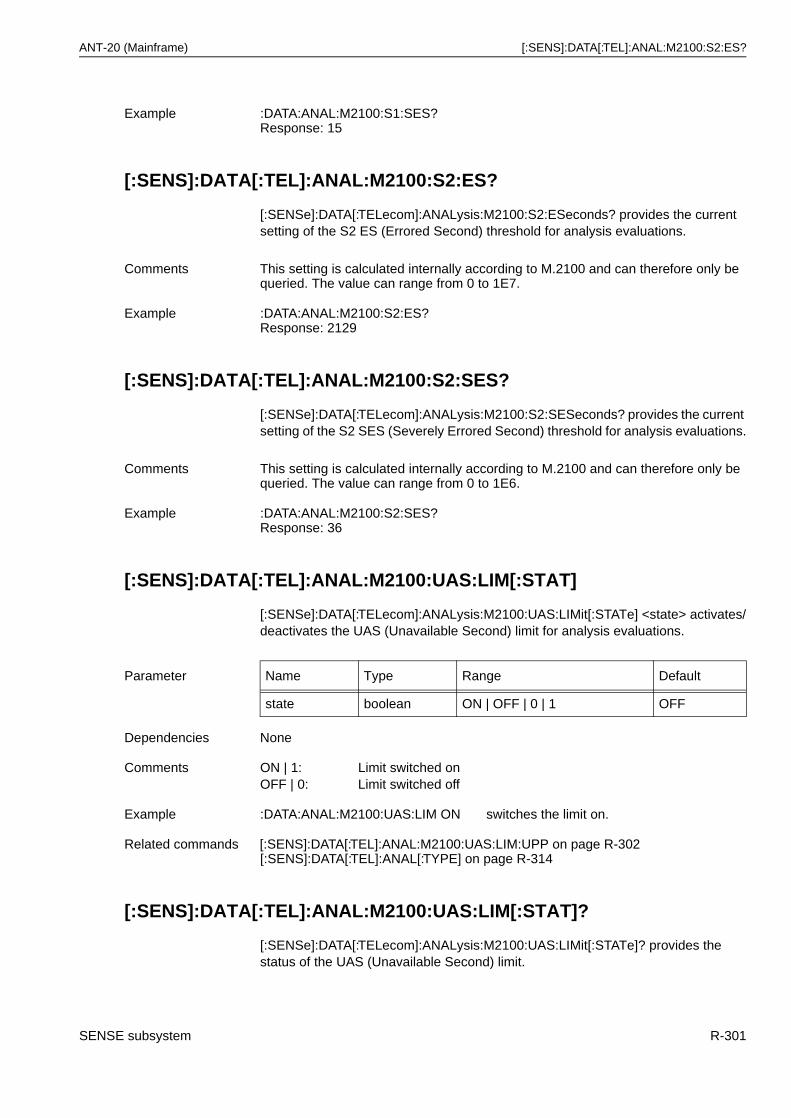
ANT-20 (Mainframe) [:SENS]:DATA[:TEL]:ANAL:M2100:S2:ES?
[:SENS]:DATA[:TEL]:ANAL:M2100:S2:ES?
[:SENSe]:DATA[:TELecom]:ANALysis:M2100:S2:ESeconds? provides the current setting of the S2 ES (Errored Second) threshold for analysis evaluations.
[:SENS]:DATA[:TEL]:ANAL:M2100:S2:SES?
[:SENSe]:DATA[:TELecom]:ANALysis:M2100:S2:SESeconds? provides the current setting of the S2 SES (Severely Errored Second) threshold for analysis evaluations.
[:SENS]:DATA[:TEL]:ANAL:M2100:UAS:LIM[:STAT]
[:SENSe]:DATA[:TELecom]:ANALysis:M2100:UAS:LIMit[:STATe] <state> activates/deactivates the UAS (Unavailable Second) limit for analysis evaluations.
[:SENS]:DATA[:TEL]:ANAL:M2100:UAS:LIM[:STAT]?
[:SENSe]:DATA[:TELecom]:ANALysis:M2100:UAS:LIMit[:STATe]? provides the status of the UAS (Unavailable Second) limit.
Example :DATA:ANAL:M2100:S1:SES?Response: 15
Comments This setting is calculated internally according to M.2100 and can therefore only be queried. The value can range from 0 to 1E7.
Example :DATA:ANAL:M2100:S2:ES?Response: 2129
Comments This setting is calculated internally according to M.2100 and can therefore only be queried. The value can range from 0 to 1E6.
Example :DATA:ANAL:M2100:S2:SES?Response: 36
Parameter Name Type Range Default
state boolean ON | OFF | 0 | 1 OFF
Dependencies None
Comments ON | 1: Limit switched onOFF | 0: Limit switched off
Example :DATA:ANAL:M2100:UAS:LIM ON switches the limit on.
Related commands [:SENS]:DATA[:TEL]:ANAL:M2100:UAS:LIM:UPP on page R-302[:SENS]:DATA[:TEL]:ANAL[:TYPE] on page R-314
SENSE subsystem R-301
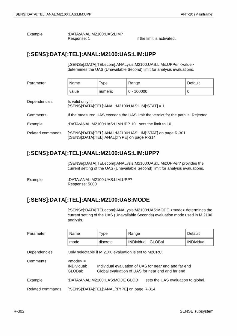
[:SENS]:DATA[:TEL]:ANAL:M2100:UAS:LIM:UPP ANT-20 (Mainframe)
[:SENS]:DATA[:TEL]:ANAL:M2100:UAS:LIM:UPP
[:SENSe]:DATA[:TELecom]:ANALysis:M2100:UAS:LIMit:UPPer <value> determines the UAS (Unavailable Second) limit for analysis evaluations.
[:SENS]:DATA[:TEL]:ANAL:M2100:UAS:LIM:UPP?
[:SENSe]:DATA[:TELecom]:ANALysis:M2100:UAS:LIMit:UPPer? provides the current setting of the UAS (Unavailable Second) limit for analysis evaluations.
[:SENS]:DATA[:TEL]:ANAL:M2100:UAS:MODE
[:SENSe]:DATA[:TELecom]:ANALysis:M2100:UAS:MODE <mode> determines the current setting of the UAS (Unavailable Seconds) evaluation mode used in M.2100 analysis.
Example :DATA:ANAL:M2100:UAS:LIM?Response: 1 if the limit is activated.
Parameter Name Type Range Default
value numeric 0 - 100000 0
Dependencies Is valid only if:[:SENS]:DATA[:TEL]:ANAL:M2100:UAS:LIM[:STAT] = 1
Comments If the measured UAS exceeds the UAS limit the verdict for the path is: Rejected.
Example :DATA:ANAL:M2100:UAS:LIM:UPP 10 sets the limit to 10.
Related commands [:SENS]:DATA[:TEL]:ANAL:M2100:UAS:LIM[:STAT] on page R-301[:SENS]:DATA[:TEL]:ANAL[:TYPE] on page R-314
Example :DATA:ANAL:M2100:UAS:LIM:UPP?Response: 5000
Parameter Name Type Range Default
mode discrete INDividual | GLOBal INDividual
Dependencies Only selectable if M.2100 evaluation is set to M2CRC.
Comments <mode> =INDividual: Individual evaluation of UAS for near end and far endGLOBal: Global evaluation of UAS for near end and far end
Example :DATA:ANAL:M2100:UAS:MODE GLOB sets the UAS evaluation to global.
Related commands [:SENS]:DATA[:TEL]:ANAL[:TYPE] on page R-314
R-302 SENSE subsystem
ANT-20 (Mainframe) [:SENS]:DATA[:TEL]:ANAL:M2100:UAS:MODE?
[:SENS]:DATA[:TEL]:ANAL:M2100:UAS:MODE?
[:SENSe]:DATA[:TELecom]:ANALysis:M2100:UAS:MODE? provides the status of the UAS (Unavailable Seconds) evaluation mode used in M.2100 analysis.
Example :DATA:ANAL:M2100:UAS:MODE?Response: INDI for individual UAS evaluation mode.
SENSE subsystem R-303
[:SENS]:DATA[:TEL]:ANAL:M2101:ALL ANT-20 (Mainframe)
[:SENS]:DATA[:TEL]:ANAL:M2101:ALL
[:SENSe]:DATA[:TELecom]:ANALysis:M2101:ALLocation <value> determines the allocation for M.2101 analysis evaluations.
[:SENS]:DATA[:TEL]:ANAL:M2101:ALL?
[:SENSe]:DATA[:TELecom]:ANALysis:M2101:ALLocation? provides the current setting of the allocation for analysis evaluations.
[:SENS]:DATA[:TEL]:ANAL:M2101:BISO:BBE?
[:SENSe]:DATA[:TELecom]:ANALysis:M2101:BISObjective:BBErrors? provides the current setting of the BISO (Bringing Into Service Objectives) BBE (Background Block Error) threshold for analysis evaluations.
Parameter Name Type Range Default
value numeric 0.1 - 100 100
Dependencies None
Comments The BISO value (Bringing Into Service Objective) and hence the S1 and S2 thresholds can be influenced with this parameter. The following formulas according to M.2101 are used for paths respectively sections:
BISOes/bbe for paths and regenerator sections:BISOes = (Allocation x EERPO x Test Period x BISO Multiplier) / 2BISObbe = (Allocation x EERPO x Test Period x Blocks/s x BISO Multiplier) / 2
BISOes/bbe for multiplex sections:BISOes = (Allocation x EERPO x Test Period x BISO Multiplier) / 10BISObbe = (Allocation x EERPO x Test Period x Blocks/s x BISO Multiplier) / 10
BISOses for paths and sections:BISOses = (Allocation x EERPO x Test Period x BISO Multiplier) / 2
EERPO = End to End Reference Performance Objective
Example :DATA:ANAL:M2101:ALL 10 sets the allocation to 10%.
Related commands [:SENS]:DATA[:TEL]:ANAL:M2101:BISO:MULT on page R-305[:SENS]:DATA[:TEL]:ANAL[:TYPE] on page R-314
Example :DATA:ANAL:M2101:ALL?Response: 10.0 for 10.0 % allocation.
Dependencies Is available only if:[:SENS]:DATA[:TEL]:ANAL:M2101:VERSion = M2101
Comments This setting is calculated internally according to M.2101 and can therefore only be queried. The value can range from 0 to 1E12.
R-304 SENSE subsystem
ANT-20 (Mainframe) [:SENS]:DATA[:TEL]:ANAL:M2101:BISO:ES?
[:SENS]:DATA[:TEL]:ANAL:M2101:BISO:ES?
[:SENSe]:DATA[:TELecom]:ANALysis:M2101:BISObjective:ESeconds? provides the current setting of the BISO (Bringing Into Service Objectives) ES (Errored Second) threshold for analysis evaluations.
[:SENS]:DATA[:TEL]:ANAL:M2101:BISO:MULT
[:SENSe]:DATA[:TELecom]:ANALysis:M2101:BISObjective:MULTiplier <value> determines the multiplier value for M.2101 analysis evaluations.
[:SENS]:DATA[:TEL]:ANAL:M2101:BISO:MULT?
[:SENSe]:DATA[:TELecom]:ANALysis:M2101:BISObjective:MULTiplier? provides the current setting of the BISO multiplier for analysis evaluations.
Example :DATA:ANAL:M2101:BISO:BBE?Response: 9677
Comments This setting is calculated internally according to M.2101 and can therefore only be queried. The value can range from 0 to 1E7.
Example :DATA:ANAL:M2101:BISO:ES?Response: 2039
Parameter Name Type Range Default
value numeric 0.1 - 100 1
Dependencies None
Comments The BISO value (Bringing Into Service Objective) and hence the S1 and S2 thresholds can be influenced with this parameter. The following formulas according to M.2101 are used for paths respectively sections:
BISOes/bbe for paths and regenerator sections:BISOes = (Allocation x EERPO x Test Period x BISO Multiplier) / 2BISObbe = (Allocation x EERPO x Test Period x Blocks/s x BISO Multiplier) / 2
BISOes/bbe for multiplex sections:BISOes = (Allocation x EERPO x Test Period x BISO Multiplier) / 10BISObbe = (Allocation x EERPO x Test Period x Blocks/s x BISO Multiplier) / 10
BISOses for paths and sections:BISOses = (Allocation x EERPO x Test Period x BISO Multiplier) / 2
EERPO = End to End Reference Performance Objective
Example :DATA:ANAL:M2101:BISO:MULT 10 sets the multiplier to 10.
Related commands [:SENS]:DATA[:TEL]:ANAL:M2101:ALL on page R-304[:SENS]:DATA[:TEL]:ANAL[:TYPE] on page R-314
SENSE subsystem R-305
[:SENS]:DATA[:TEL]:ANAL:M2101:BISO:SEP? ANT-20 (Mainframe)
[:SENS]:DATA[:TEL]:ANAL:M2101:BISO:SEP?
[:SENSe]:DATA[:TELecom]:ANALysis:M2101:BISObjective:SEPeriod? provides the current setting of the BISO SEP (Severely Errored Period) threshold for analysis evaluations.
[:SENS]:DATA[:TEL]:ANAL:M2101:BISO:SES?
[:SENSe]:DATA[:TELecom]:ANALysis:M2101:BISObjective:SESeconds? provides the current setting of the BISO SES (Severely Errored Second) threshold for analysis evaluations.
[:SENS]:DATA[:TEL]:ANAL:M2101:EVAL
[:SENSe]:DATA[:TELecom]:ANALysis:M2101:EVALuation <evaluation> determines the current setting of the anomaly evaluation type used in M.2101 analysis.
Example :DATA:ANAL:M2101:BISO:MULT?Response: 5
Dependencies Is available only if:[:SENS]:DATA[:TEL]:ANAL:M2101:VERSion = M2101
Comments This setting is calculated internally according to M.2101 and can therefore only be queried. The value can range from 0 to 1E6.
Example :DATA:ANAL:M2101:BISO:SEP?Response: 16
Comments This setting is calculated internally according to M.2101 and can therefore only be queried. The value can range from 0 to 1E6.
Example :DATA:ANAL:M2101:BISO:SES?Response: 51
Parameter Name Type Range Default
evaluation discrete NONE | RSB1 | MSB2 | HPB3| LPBIP | TCM | TSE
HPB3
Dependencies If not set to TSE, a matching setting of the receiver signal is required to allow the selected analysis evaluation.
R-306 SENSE subsystem
ANT-20 (Mainframe) [:SENS]:DATA[:TEL]:ANAL:M2101:EVAL?
[:SENS]:DATA[:TEL]:ANAL:M2101:EVAL?
[:SENSe]:DATA[:TELecom]:ANALysis:M2101:EVALuation? provides the current setting of the anomaly evaluation type used in M.2101 analysis.
[:SENS]:DATA[:TEL]:ANAL:M2101:S1:BBE?
[:SENSe]:DATA[:TELecom]:ANALysis:M2101:S1:BBErrors? provides the current setting of the S1 BBE (Background Block Error) threshold for analysis evaluations.
[:SENS]:DATA[:TEL]:ANAL:M2101:S1:ES?
[:SENSe]:DATA[:TELecom]:ANALysis:M2101:S1:ESeconds? provides the current setting of the S1 ES (Errored Second) threshold for analysis evaluations.
Comments <evaluation> =NONE: No M.2101 analysisRSB1: Perform analysis for B1 errors in SDH signalsMSB2: Perform analysis for B2 errors in SDH signalsHPB3: Perform analysis for B3 errors in SDH signalsLPBIP: Perform analysis for LPBIP errors in SDH signalsTCM: Perform analysis for TCM (Tandem Connection Monitoring) Bytes
N1/N2 (Z6)Not yet available!
TSE: Perform analysis for TSE (test sequence errors)
Example :DATA:ANAL:M2101:EVAL HPB3 sets high path B3 error evaluation.
Related commands [:SENS]:DATA[:TEL]:ANAL[:TYPE] on page R-314
Example :DATA:ANAL:M2101:EVAL?Response: TSE if M.2101 TSE measurement is activated.
Dependencies Is available only if:[:SENS]:DATA[:TEL]:ANAL:M2101:VERSion = M2101
Comments This setting is calculated internally according to M.2101 and can therefore only be queried. The value can range from 0 to 1E12.
Example :DATA:ANAL:M2101:S1:BBE?Response: 9480
Comments This setting is calculated internally according to M.2101 and can therefore only be queried. The value can range from 0 to 1E7.
Example :DATA:ANAL:M2101:S1:ES?Response: 1847
SENSE subsystem R-307
[:SENS]:DATA[:TEL]:ANAL:M2101:S1:SEP? ANT-20 (Mainframe)
[:SENS]:DATA[:TEL]:ANAL:M2101:S1:SEP?
[:SENSe]:DATA[:TELecom]:ANALysis:M2101:S1:SEPeriod? provides the current setting of the S1 SEP (Severely Errored Period) threshold for analysis evaluations.
[:SENS]:DATA[:TEL]:ANAL:M2101:S1:SES?
[:SENSe]:DATA[:TELecom]:ANALysis:M2101:S1:SESeconds? provides the current setting of the S1 SES (Severely Errored Second) threshold for analysis evaluations.
[:SENS]:DATA[:TEL]:ANAL:M2101:S2:BBE?
[:SENSe]:DATA[:TELecom]:ANALysis:M2101:S2:BBErrors? provides the current setting of the S2 BBE (Background Block Error) threshold for analysis evaluations.
[:SENS]:DATA[:TEL]:ANAL:M2101:S2:ES?
[:SENSe]:DATA[:TELecom]:ANALysis:M2101:S2:ESeconds? provides the current setting of the S2 ES (Errored Second) threshold for analysis evaluations.
Dependencies Is available only if:[:SENS]:DATA[:TEL]:ANAL:M2101:VERSion = M2101
Comments This setting is calculated internally according to M.2101 and can therefore only be queried. The value can range from 0 to 1E6.
Example :DATA:ANAL:M2101:S1:SEP?Response: 4
Comments This setting is calculated internally according to M.2101 and can therefore only be queried. The value can range from 0 to 1E6.
Example :DATA:ANAL:M2101:S1:SES?Response: 166
Dependencies Is available only if:[:SENS]:DATA[:TEL]:ANAL:M2101:VERSion = M2101
Comments This setting is calculated internally according to M.2101 and can therefore only be queried. The value can range from 0 to 1E12.
Example :DATA:ANAL:M2101:S2:BBE?Response: 9874
Comments This setting is calculated internally according to M.2101 and can therefore only be queried. The value can range from 0 to 1E7.
Example :DATA:ANAL:M2101:S2:ES?Response: 2023
R-308 SENSE subsystem
ANT-20 (Mainframe) [:SENS]:DATA[:TEL]:ANAL:M2101:S2:SEP?
[:SENS]:DATA[:TEL]:ANAL:M2101:S2:SEP?
[:SENSe]:DATA[:TELecom]:ANALysis:M2101:S2:SEPeriod? provides the current setting of the S2 SEP (Severely Errored Period) threshold for analysis evaluations.
[:SENS]:DATA[:TEL]:ANAL:M2101:S2:SES?
[:SENSe]:DATA[:TELecom]:ANALysis:M2101:S2:SESeconds? provides the current setting of the S2 SES (Severely Errored Second) threshold for analysis evaluations.
[:SENS]:DATA[:TEL]:ANAL:M2101:SEPI[:STAT]
[:SENSe]:DATA[:TELecom]:ANALysis:M2101:SEPIntensity[:STATe] <state> activates/deactivates the consideration of SEPI (Severely Errored Period Intensity) in the calculation of the verdict.
[:SENS]:DATA[:TEL]:ANAL:M2101:SEPI[:STAT]?
[:SENSe]:DATA[:TELecom]:ANALysis:M2101:SEPIntensity[:STATe]? provides the status of the consideration of SEPI (Severely Errored Period Intensity) in the calculation of the verdict.
Dependencies Is available only if:[:SENS]:DATA[:TEL]:ANAL:M2101:VERSion = M2101
Comments This setting is calculated internally according to M.2101 and can therefore only be queried. The value can range from 0 to 1E6.
Example :DATA:ANAL:M2101:S2:SEP?Response: 16
Comments This setting is calculated internally according to M.2101 and can therefore only be queried. The value can range from 0 to 1E6.
Example :DATA:ANAL:M2101:S2:SES?Response: 222
Parameter Name Type Range Default
state boolean ON | OFF | 0 | 1 ON
Dependencies Is available only if:[:SENS]:DATA[:TEL]:ANAL:M2101:VERSion = M2101
Comments ON | 1: Consideration switched onOFF | 0: Consideration switched off
Example :DATA:ANAL:M2101:SEPI ON switches the consideration on.
Related commands [:SENS]:DATA[:TEL]:ANAL:M2101:VERSion on page R-311
SENSE subsystem R-309
[:SENS]:DATA[:TEL]:ANAL:M2101:UAS:LIM[:STAT] ANT-20 (Mainframe)
[:SENS]:DATA[:TEL]:ANAL:M2101:UAS:LIM[:STAT]
[:SENSe]:DATA[:TELecom]:ANALysis:M2101:UAS:LIMit[:STATe] <state> activates/deactivates the UAS (Unavailable Second) limit for analysis evaluations.
[:SENS]:DATA[:TEL]:ANAL:M2101:UAS:LIM[:STAT]?
[:SENSe]:DATA[:TELecom]:ANALysis:M2101:UAS:LIMit[:STATe]? provides the status of the UAS (Unavailable Second) limit.
[:SENS]:DATA[:TEL]:ANAL:M2101:UAS:LIM:UPP
[:SENSe]:DATA[:TELecom]:ANALysis:M2101:UAS:LIMit:UPPer <value> determines the UAS (unavailable second) limit for analysis evaluations.
Example :DATA:ANAL:M2101:SEPI?Response: 1 if the consideration is activated.
Parameter Name Type Range Default
state boolean ON | OFF | 0 | 1 OFF
Dependencies None
Comments ON | 1: Limit switched onOFF | 0: Limit switched off
Example :DATA:ANAL:M2101:UAS:LIM ON switches the limit on.
Related commands [:SENS]:DATA[:TEL]:ANAL:M2101:UAS:LIM:UPP on page R-310[:SENS]:DATA[:TEL]:ANAL[:TYPE] on page R-314
Example :DATA:ANAL:M2101:UAS:LIM?Response: 1 if the limit is activated.
Parameter Name Type Range Default
value numeric 0 - 100000 0
Dependencies Is valid only if:[:SENS]:DATA[:TEL]:ANAL:M2101:UAS:LIM[:STAT] = 1
Comments If the measured UAS exceeds the UAS limit the verdict for the path is: Rejected.
Example :DATA:ANAL:M2101:UAS:LIM:UPP 10 sets the limit to 10.
Related commands [:SENS]:DATA[:TEL]:ANAL:M2101:UAS:LIM[:STAT] on page R-310[:SENS]:DATA[:TEL]:ANAL[:TYPE] on page R-314
R-310 SENSE subsystem
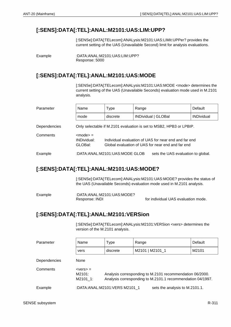
ANT-20 (Mainframe) [:SENS]:DATA[:TEL]:ANAL:M2101:UAS:LIM:UPP?
[:SENS]:DATA[:TEL]:ANAL:M2101:UAS:LIM:UPP?
[:SENSe]:DATA[:TELecom]:ANALysis:M2101:UAS:LIMit:UPPer? provides the current setting of the UAS (Unavailable Second) limit for analysis evaluations.
[:SENS]:DATA[:TEL]:ANAL:M2101:UAS:MODE
[:SENSe]:DATA[:TELecom]:ANALysis:M2101:UAS:MODE <mode> determines the current setting of the UAS (Unavailable Seconds) evaluation mode used in M.2101 analysis.
[:SENS]:DATA[:TEL]:ANAL:M2101:UAS:MODE?
[:SENSe]:DATA[:TELecom]:ANALysis:M2101:UAS:MODE? provides the status of the UAS (Unavailable Seconds) evaluation mode used in M.2101 analysis.
[:SENS]:DATA[:TEL]:ANAL:M2101:VERSion
[:SENSe]:DATA[:TELecom]:ANALysis:M2101:VERSion <vers> determines the version of the M.2101 analysis.
Example :DATA:ANAL:M2101:UAS:LIM:UPP?Response: 5000
Parameter Name Type Range Default
mode discrete INDividual | GLOBal INDividual
Dependencies Only selectable if M.2101 evaluation is set to MSB2, HPB3 or LPBIP.
Comments <mode> =INDividual: Individual evaluation of UAS for near end and far endGLOBal: Global evaluation of UAS for near end and far end
Example :DATA:ANAL:M2101:UAS:MODE GLOB sets the UAS evaluation to global.
Example :DATA:ANAL:M2101:UAS:MODE?Response: INDI for individual UAS evaluation mode.
Parameter Name Type Range Default
vers discrete M2101 | M2101_1 M2101
Dependencies None
Comments <vers> =M2101: Analysis corresponding to M.2101 recommendation 06/2000.M2101_1: Analysis corresponding to M.2101.1 recommendation 04/1997.
Example :DATA:ANAL:M2101:VERS M2101_1 sets the analysis to M.2101.1.
SENSE subsystem R-311
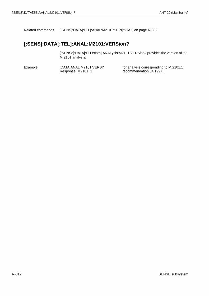
[:SENS]:DATA[:TEL]:ANAL:M2101:VERSion? ANT-20 (Mainframe)
[:SENS]:DATA[:TEL]:ANAL:M2101:VERSion?
[:SENSe]:DATA[:TELecom]:ANALysis:M2101:VERSion? provides the version of the M.2101 analysis.
Related commands [:SENS]:DATA[:TEL]:ANAL:M2101:SEPI[:STAT] on page R-309
Example :DATA:ANAL:M2101:VERS?Response: M2101_1
for analysis corresponding to M.2101.1 recommendation 04/1997.
R-312 SENSE subsystem
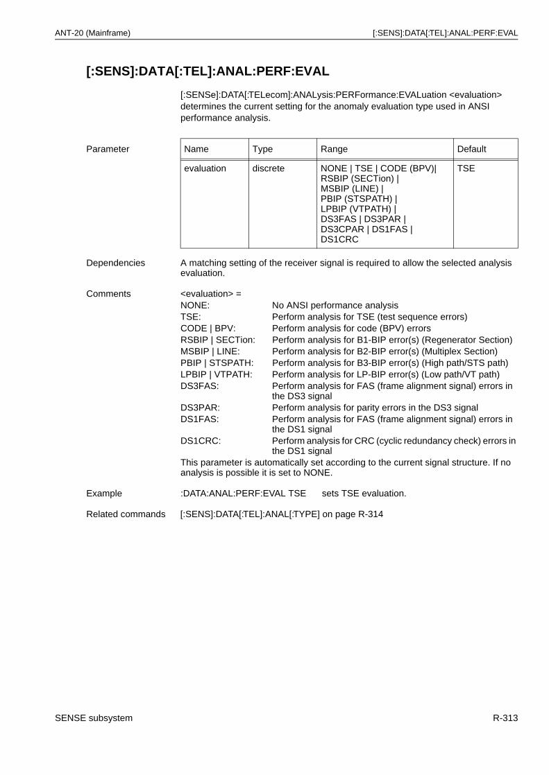
ANT-20 (Mainframe) [:SENS]:DATA[:TEL]:ANAL:PERF:EVAL
[:SENS]:DATA[:TEL]:ANAL:PERF:EVAL
[:SENSe]:DATA[:TELecom]:ANALysis:PERFormance:EVALuation <evaluation> determines the current setting for the anomaly evaluation type used in ANSI performance analysis.
Parameter Name Type Range Default
evaluation discrete NONE | TSE | CODE (BPV)|RSBIP (SECTion) |MSBIP (LINE) |PBIP (STSPATH) |LPBIP (VTPATH) |DS3FAS | DS3PAR |DS3CPAR | DS1FAS |DS1CRC
TSE
Dependencies A matching setting of the receiver signal is required to allow the selected analysis evaluation.
Comments <evaluation> =NONE: No ANSI performance analysisTSE: Perform analysis for TSE (test sequence errors)CODE | BPV: Perform analysis for code (BPV) errorsRSBIP | SECTion: Perform analysis for B1-BIP error(s) (Regenerator Section)MSBIP | LINE: Perform analysis for B2-BIP error(s) (Multiplex Section)PBIP | STSPATH: Perform analysis for B3-BIP error(s) (High path/STS path)LPBIP | VTPATH: Perform analysis for LP-BIP error(s) (Low path/VT path)DS3FAS: Perform analysis for FAS (frame alignment signal) errors in
the DS3 signalDS3PAR: Perform analysis for parity errors in the DS3 signalDS1FAS: Perform analysis for FAS (frame alignment signal) errors in
the DS1 signalDS1CRC: Perform analysis for CRC (cyclic redundancy check) errors in
the DS1 signalThis parameter is automatically set according to the current signal structure. If no analysis is possible it is set to NONE.
Example :DATA:ANAL:PERF:EVAL TSE sets TSE evaluation.
Related commands [:SENS]:DATA[:TEL]:ANAL[:TYPE] on page R-314
SENSE subsystem R-313
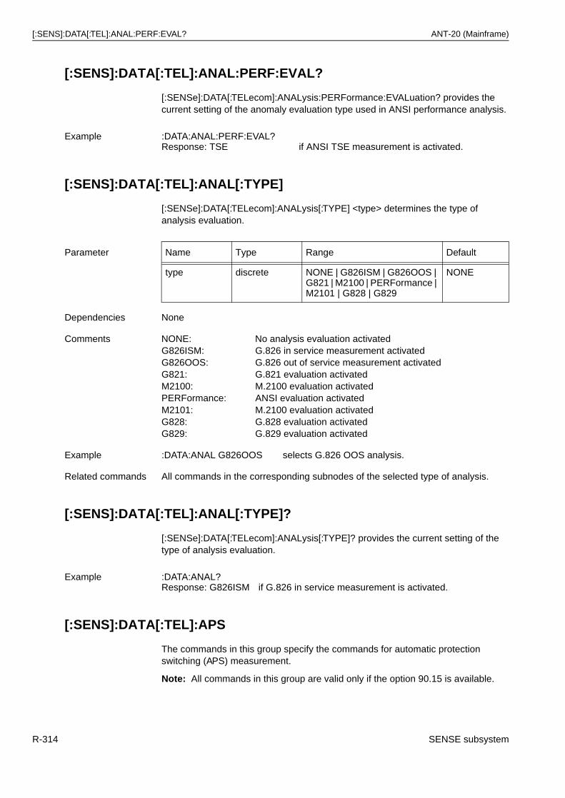
[:SENS]:DATA[:TEL]:ANAL:PERF:EVAL? ANT-20 (Mainframe)
[:SENS]:DATA[:TEL]:ANAL:PERF:EVAL?
[:SENSe]:DATA[:TELecom]:ANALysis:PERFormance:EVALuation? provides the current setting of the anomaly evaluation type used in ANSI performance analysis.
[:SENS]:DATA[:TEL]:ANAL[:TYPE]
[:SENSe]:DATA[:TELecom]:ANALysis[:TYPE] <type> determines the type of analysis evaluation.
[:SENS]:DATA[:TEL]:ANAL[:TYPE]?
[:SENSe]:DATA[:TELecom]:ANALysis[:TYPE]? provides the current setting of the type of analysis evaluation.
[:SENS]:DATA[:TEL]:APS
The commands in this group specify the commands for automatic protection switching (APS) measurement.
Note: All commands in this group are valid only if the option 90.15 is available.
Example :DATA:ANAL:PERF:EVAL?Response: TSE if ANSI TSE measurement is activated.
Parameter Name Type Range Default
type discrete NONE | G826ISM | G826OOS | G821 | M2100 | PERFormance | M2101 | G828 | G829
NONE
Dependencies None
Comments NONE: No analysis evaluation activatedG826ISM: G.826 in service measurement activatedG826OOS: G.826 out of service measurement activatedG821: G.821 evaluation activatedM2100: M.2100 evaluation activatedPERFormance: ANSI evaluation activatedM2101: M.2100 evaluation activatedG828: G.828 evaluation activatedG829: G.829 evaluation activated
Example :DATA:ANAL G826OOS selects G.826 OOS analysis.
Related commands All commands in the corresponding subnodes of the selected type of analysis.
Example :DATA:ANAL?Response: G826ISM if G.826 in service measurement is activated.
R-314 SENSE subsystem
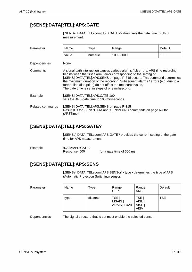
ANT-20 (Mainframe) [:SENS]:DATA[:TEL]:APS:GATE
[:SENS]:DATA[:TEL]:APS:GATE
[:SENSe]:DATA[:TELecom]:APS:GATE <value> sets the gate time for APS measurement.
[:SENS]:DATA[:TEL]:APS:GATE?
[:SENSe]:DATA[:TELecom]:APS:GATE? provides the current setting of the gate time for APS measurement.
[:SENS]:DATA[:TEL]:APS:SENS
[:SENSe]:DATA[:TELecom]:APS:SENSor] <type> determines the type of APS (Automatic Protection Switching) sensor.
Parameter Name Type Range Default
value numeric 100 - 5000 100
Dependencies None
Comments A signal path interruption causes various alarms / bit errors. APS time recording begins when the first alarm / error corresponding to the setting of [:SENS]:DATA[:TEL]:APS:SENS on page R-315 occurs. This command determines the maximum duration of the recording. Subsequent alarms / errors (e.g. due to a further line disruption) do not affect the measured value.The gate time is set in steps of one millisecond.
Example [:SENS]:DATA[:TEL]:APS:GATE 100sets the APS gate time to 100 milliseconds.
Related commands [:SENS]:DATA[:TEL]:APS:SENS on page R-315Result IDs for :SENS:DATA and :SENS:FUNC commands on page R-382 (APSTime)
Example :DATA:APS:GATE?Response: 500 for a gate time of 500 ms.
Parameter Name Type RangeCEPT
RangeANSI
Default
type discrete TSE | MSAIS | AUAIS | TUAIS
TSE | AISL | AISP |AISV
TSE
Dependencies The signal structure that is set must enable the selected sensor.
SENSE subsystem R-315
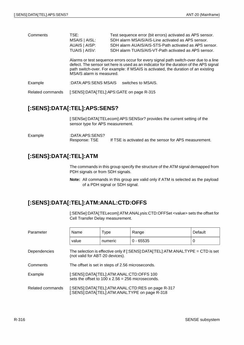
[:SENS]:DATA[:TEL]:APS:SENS? ANT-20 (Mainframe)
[:SENS]:DATA[:TEL]:APS:SENS?
[:SENSe]:DATA[:TELecom]:APS:SENSor? provides the current setting of the sensor type for APS measurement.
[:SENS]:DATA[:TEL]:ATM
The commands in this group specify the structure of the ATM signal demapped from PDH signals or from SDH signals.
Note: All commands in this group are valid only if ATM is selected as the payload of a PDH signal or SDH signal.
[:SENS]:DATA[:TEL]:ATM:ANAL:CTD:OFFS
[:SENSe]:DATA[:TELecom]:ATM:ANALysis:CTD:OFFSet <value> sets the offset for Cell Transfer Delay measurement.
Comments TSE: Test sequence error (bit errors) activated as APS sensor.MSAIS | AISL: SDH alarm MSAIS/AIS-Line activated as APS sensor.AUAIS | AISP: SDH alarm AUAIS/AIS-STS-Path activated as APS sensor.TUAIS | AISV: SDH alarm TUAIS/AIS-VT-Path activated as APS sensor.
Alarms or test sequence errors occur for every signal path switch-over due to a line defect. The sensor set here is used as an indicator for the duration of the APS signal path switch-over. For example: If MSAIS is activated, the duration of an existing MSAIS alarm is measured.
Example :DATA:APS:SENS MSAIS switches to MSAIS.
Related commands [:SENS]:DATA[:TEL]:APS:GATE on page R-315
Example :DATA:APS:SENS?Response: TSE If TSE is activated as the sensor for APS measurement.
Parameter Name Type Range Default
value numeric 0 - 65535 0
Dependencies The selection is effective only if [:SENS]:DATA[:TEL]:ATM:ANAL:TYPE = CTD is set (not valid for ABT-20 devices).
Comments The offset is set in steps of 2.56 microseconds.
Example [:SENS]:DATA[:TEL]:ATM:ANAL:CTD:OFFS 100sets the offset to 100 x 2.56 = 256 microseconds.
Related commands [:SENS]:DATA[:TEL]:ATM:ANAL:CTD:RES on page R-317[:SENS]:DATA[:TEL]:ATM:ANAL:TYPE on page R-318
R-316 SENSE subsystem
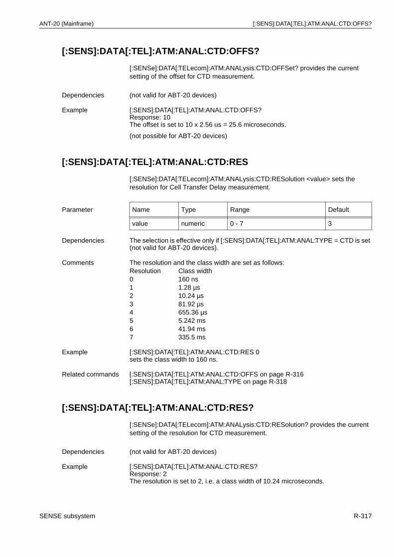
ANT-20 (Mainframe) [:SENS]:DATA[:TEL]:ATM:ANAL:CTD:OFFS?
[:SENS]:DATA[:TEL]:ATM:ANAL:CTD:OFFS?
[:SENSe]:DATA[:TELecom]:ATM:ANALysis:CTD:OFFSet? provides the current setting of the offset for CTD measurement.
[:SENS]:DATA[:TEL]:ATM:ANAL:CTD:RES
[:SENSe]:DATA[:TELecom]:ATM:ANALysis:CTD:RESolution <value> sets the resolution for Cell Transfer Delay measurement.
[:SENS]:DATA[:TEL]:ATM:ANAL:CTD:RES?
[:SENSe]:DATA[:TELecom]:ATM:ANALysis:CTD:RESolution? provides the current setting of the resolution for CTD measurement.
Dependencies (not valid for ABT-20 devices)
Example [:SENS]:DATA[:TEL]:ATM:ANAL:CTD:OFFS?Response: 10The offset is set to 10 x 2.56 us = 25.6 microseconds.
(not possible for ABT-20 devices)
Parameter Name Type Range Default
value numeric 0 - 7 3
Dependencies The selection is effective only if [:SENS]:DATA[:TEL]:ATM:ANAL:TYPE = CTD is set (not valid for ABT-20 devices).
Comments The resolution and the class width are set as follows:Resolution Class width0 160 ns1 1.28 µs2 10.24 µs3 81.92 µs4 655.36 µs5 5.242 ms6 41.94 ms7 335.5 ms
Example [:SENS]:DATA[:TEL]:ATM:ANAL:CTD:RES 0sets the class width to 160 ns.
Related commands [:SENS]:DATA[:TEL]:ATM:ANAL:CTD:OFFS on page R-316[:SENS]:DATA[:TEL]:ATM:ANAL:TYPE on page R-318
Dependencies (not valid for ABT-20 devices)
Example [:SENS]:DATA[:TEL]:ATM:ANAL:CTD:RES?Response: 2The resolution is set to 2, i.e. a class width of 10.24 microseconds.
SENSE subsystem R-317
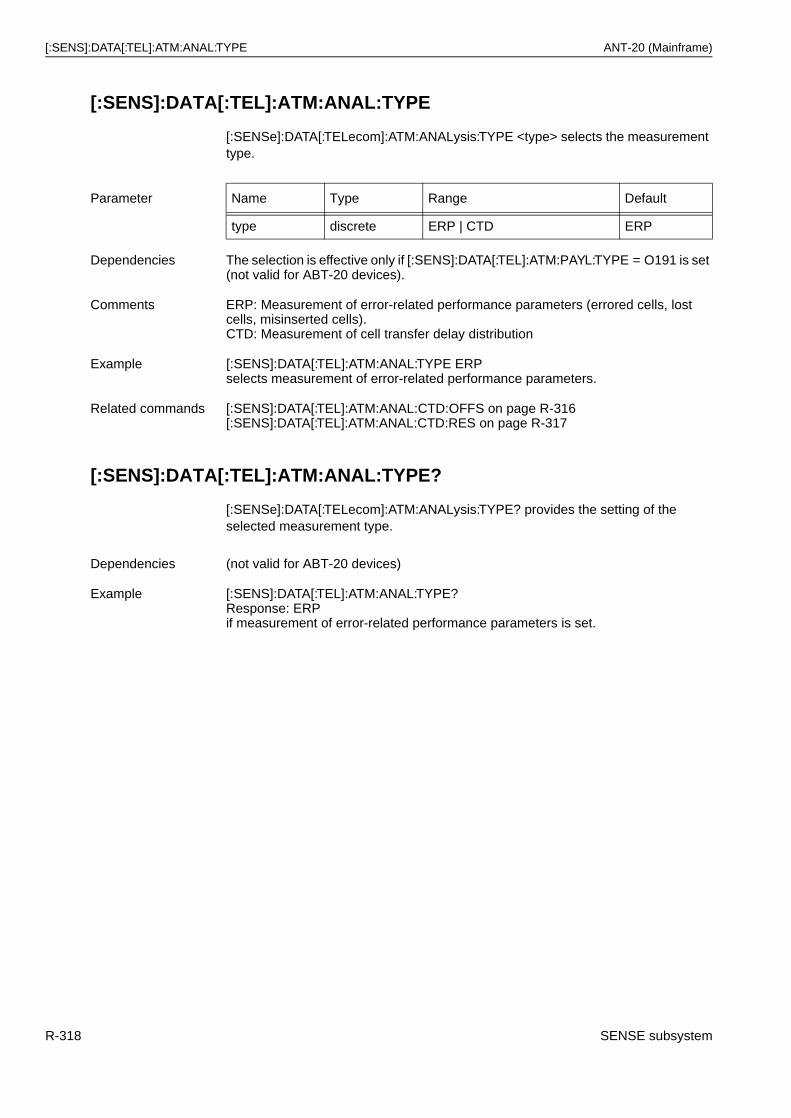
[:SENS]:DATA[:TEL]:ATM:ANAL:TYPE ANT-20 (Mainframe)
[:SENS]:DATA[:TEL]:ATM:ANAL:TYPE
[:SENSe]:DATA[:TELecom]:ATM:ANALysis:TYPE <type> selects the measurement type.
[:SENS]:DATA[:TEL]:ATM:ANAL:TYPE?
[:SENSe]:DATA[:TELecom]:ATM:ANALysis:TYPE? provides the setting of the selected measurement type.
Parameter Name Type Range Default
type discrete ERP | CTD ERP
Dependencies The selection is effective only if [:SENS]:DATA[:TEL]:ATM:PAYL:TYPE = O191 is set (not valid for ABT-20 devices).
Comments ERP: Measurement of error-related performance parameters (errored cells, lost cells, misinserted cells).CTD: Measurement of cell transfer delay distribution
Example [:SENS]:DATA[:TEL]:ATM:ANAL:TYPE ERP selects measurement of error-related performance parameters.
Related commands [:SENS]:DATA[:TEL]:ATM:ANAL:CTD:OFFS on page R-316[:SENS]:DATA[:TEL]:ATM:ANAL:CTD:RES on page R-317
Dependencies (not valid for ABT-20 devices)
Example [:SENS]:DATA[:TEL]:ATM:ANAL:TYPE?Response: ERPif measurement of error-related performance parameters is set.
R-318 SENSE subsystem
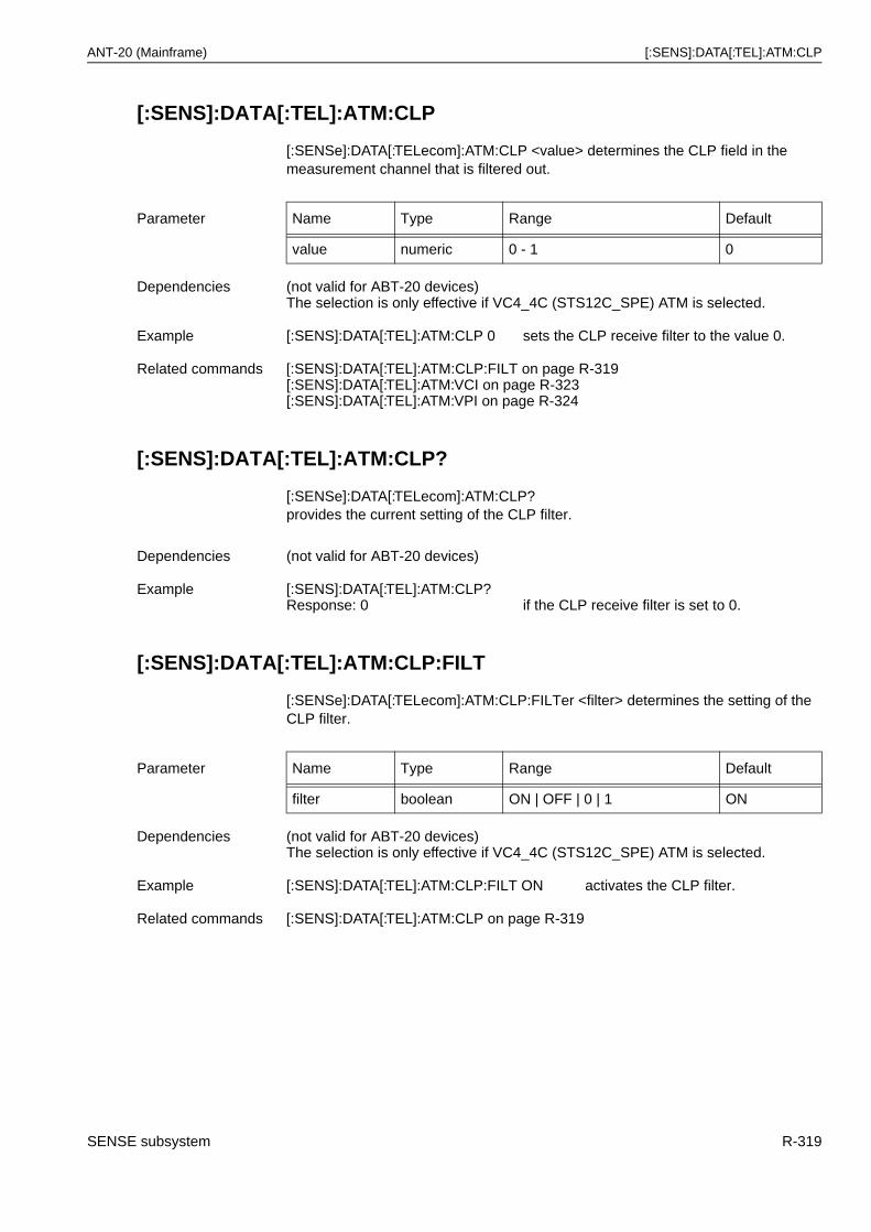
ANT-20 (Mainframe) [:SENS]:DATA[:TEL]:ATM:CLP
[:SENS]:DATA[:TEL]:ATM:CLP
[:SENSe]:DATA[:TELecom]:ATM:CLP <value> determines the CLP field in the measurement channel that is filtered out.
[:SENS]:DATA[:TEL]:ATM:CLP?
[:SENSe]:DATA[:TELecom]:ATM:CLP? provides the current setting of the CLP filter.
[:SENS]:DATA[:TEL]:ATM:CLP:FILT
[:SENSe]:DATA[:TELecom]:ATM:CLP:FILTer <filter> determines the setting of the CLP filter.
Parameter Name Type Range Default
value numeric 0 - 1 0
Dependencies (not valid for ABT-20 devices)The selection is only effective if VC4_4C (STS12C_SPE) ATM is selected.
Example [:SENS]:DATA[:TEL]:ATM:CLP 0 sets the CLP receive filter to the value 0.
Related commands [:SENS]:DATA[:TEL]:ATM:CLP:FILT on page R-319[:SENS]:DATA[:TEL]:ATM:VCI on page R-323[:SENS]:DATA[:TEL]:ATM:VPI on page R-324
Dependencies (not valid for ABT-20 devices)
Example [:SENS]:DATA[:TEL]:ATM:CLP?Response: 0 if the CLP receive filter is set to 0.
Parameter Name Type Range Default
filter boolean ON | OFF | 0 | 1 ON
Dependencies (not valid for ABT-20 devices)The selection is only effective if VC4_4C (STS12C_SPE) ATM is selected.
Example [:SENS]:DATA[:TEL]:ATM:CLP:FILT ON activates the CLP filter.
Related commands [:SENS]:DATA[:TEL]:ATM:CLP on page R-319
SENSE subsystem R-319
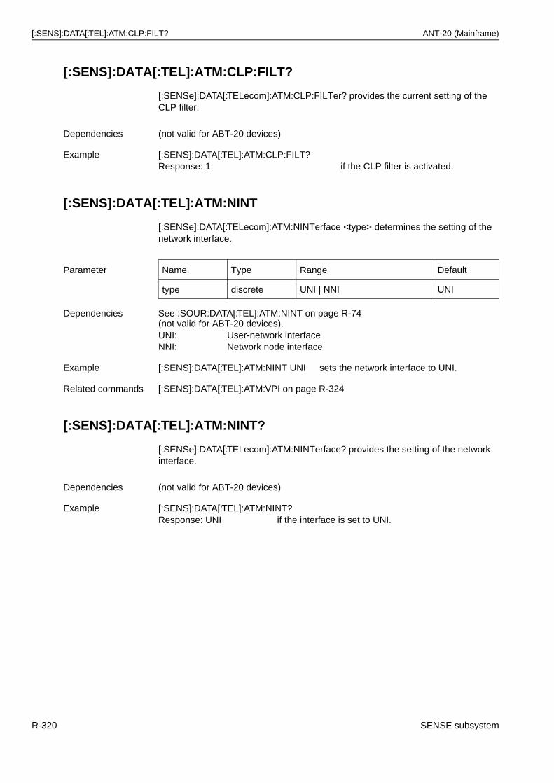
[:SENS]:DATA[:TEL]:ATM:CLP:FILT? ANT-20 (Mainframe)
[:SENS]:DATA[:TEL]:ATM:CLP:FILT?
[:SENSe]:DATA[:TELecom]:ATM:CLP:FILTer? provides the current setting of the CLP filter.
[:SENS]:DATA[:TEL]:ATM:NINT
[:SENSe]:DATA[:TELecom]:ATM:NINTerface <type> determines the setting of the network interface.
[:SENS]:DATA[:TEL]:ATM:NINT?
[:SENSe]:DATA[:TELecom]:ATM:NINTerface? provides the setting of the network interface.
Dependencies (not valid for ABT-20 devices)
Example [:SENS]:DATA[:TEL]:ATM:CLP:FILT?Response: 1 if the CLP filter is activated.
Parameter Name Type Range Default
type discrete UNI | NNI UNI
Dependencies See :SOUR:DATA[:TEL]:ATM:NINT on page R-74(not valid for ABT-20 devices).UNI: User-network interfaceNNI: Network node interface
Example [:SENS]:DATA[:TEL]:ATM:NINT UNI sets the network interface to UNI.
Related commands [:SENS]:DATA[:TEL]:ATM:VPI on page R-324
Dependencies (not valid for ABT-20 devices)
Example [:SENS]:DATA[:TEL]:ATM:NINT?Response: UNI if the interface is set to UNI.
R-320 SENSE subsystem
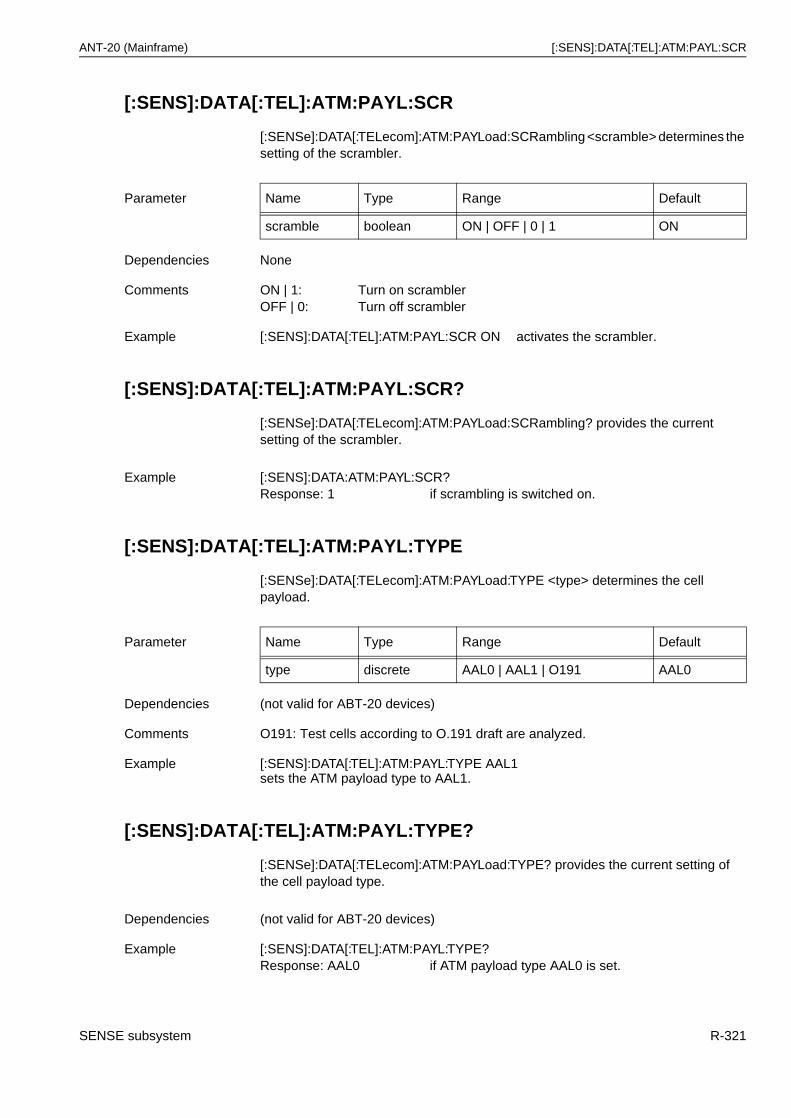
ANT-20 (Mainframe) [:SENS]:DATA[:TEL]:ATM:PAYL:SCR
[:SENS]:DATA[:TEL]:ATM:PAYL:SCR
[:SENSe]:DATA[:TELecom]:ATM:PAYLoad:SCRambling <scramble> determines the setting of the scrambler.
[:SENS]:DATA[:TEL]:ATM:PAYL:SCR?
[:SENSe]:DATA[:TELecom]:ATM:PAYLoad:SCRambling? provides the current setting of the scrambler.
[:SENS]:DATA[:TEL]:ATM:PAYL:TYPE
[:SENSe]:DATA[:TELecom]:ATM:PAYLoad:TYPE <type> determines the cell payload.
[:SENS]:DATA[:TEL]:ATM:PAYL:TYPE?
[:SENSe]:DATA[:TELecom]:ATM:PAYLoad:TYPE? provides the current setting of the cell payload type.
Parameter Name Type Range Default
scramble boolean ON | OFF | 0 | 1 ON
Dependencies None
Comments ON | 1: Turn on scramblerOFF | 0: Turn off scrambler
Example [:SENS]:DATA[:TEL]:ATM:PAYL:SCR ON activates the scrambler.
Example [:SENS]:DATA:ATM:PAYL:SCR?Response: 1 if scrambling is switched on.
Parameter Name Type Range Default
type discrete AAL0 | AAL1 | O191 AAL0
Dependencies (not valid for ABT-20 devices)
Comments O191: Test cells according to O.191 draft are analyzed.
Example [:SENS]:DATA[:TEL]:ATM:PAYL:TYPE AAL1 sets the ATM payload type to AAL1.
Dependencies (not valid for ABT-20 devices)
Example [:SENS]:DATA[:TEL]:ATM:PAYL:TYPE?Response: AAL0 if ATM payload type AAL0 is set.
SENSE subsystem R-321
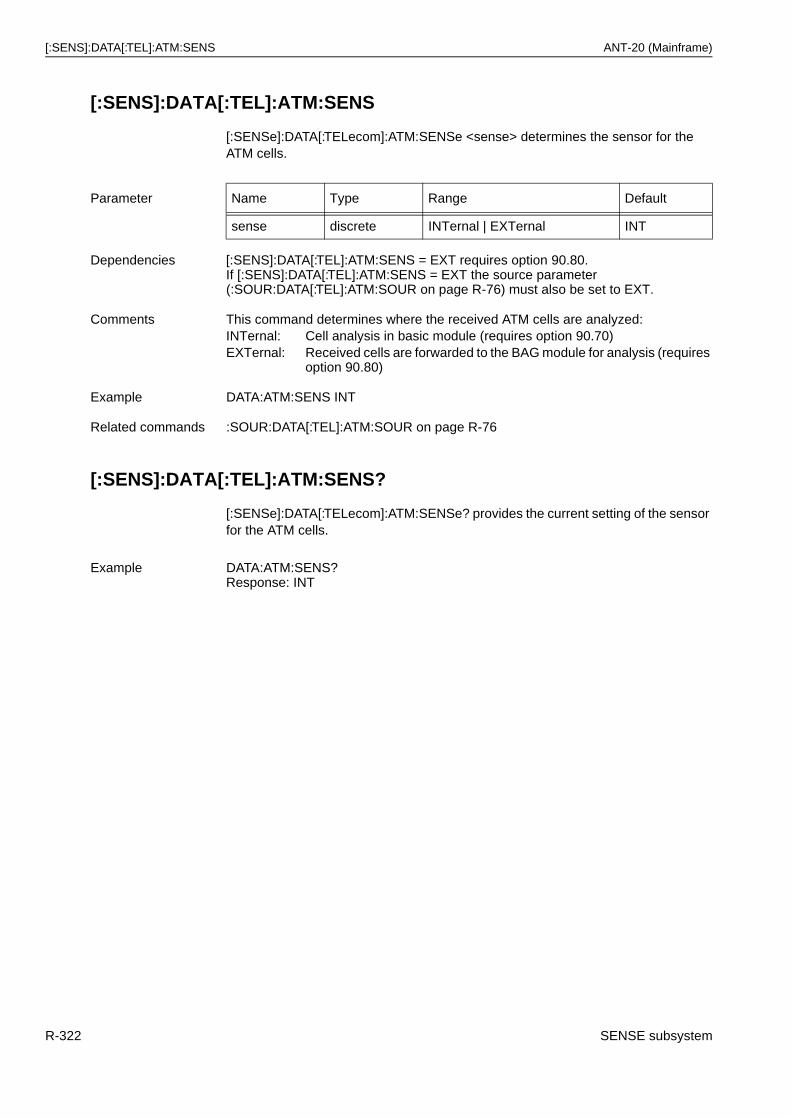
[:SENS]:DATA[:TEL]:ATM:SENS ANT-20 (Mainframe)
[:SENS]:DATA[:TEL]:ATM:SENS
[:SENSe]:DATA[:TELecom]:ATM:SENSe <sense> determines the sensor for the ATM cells.
[:SENS]:DATA[:TEL]:ATM:SENS?
[:SENSe]:DATA[:TELecom]:ATM:SENSe? provides the current setting of the sensor for the ATM cells.
Parameter Name Type Range Default
sense discrete INTernal | EXTernal INT
Dependencies [:SENS]:DATA[:TEL]:ATM:SENS = EXT requires option 90.80.If [:SENS]:DATA[:TEL]:ATM:SENS = EXT the source parameter (:SOUR:DATA[:TEL]:ATM:SOUR on page R-76) must also be set to EXT.
Comments This command determines where the received ATM cells are analyzed:INTernal: Cell analysis in basic module (requires option 90.70)EXTernal: Received cells are forwarded to the BAG module for analysis (requires
option 90.80)
Example DATA:ATM:SENS INT
Related commands :SOUR:DATA[:TEL]:ATM:SOUR on page R-76
Example DATA:ATM:SENS?Response: INT
R-322 SENSE subsystem
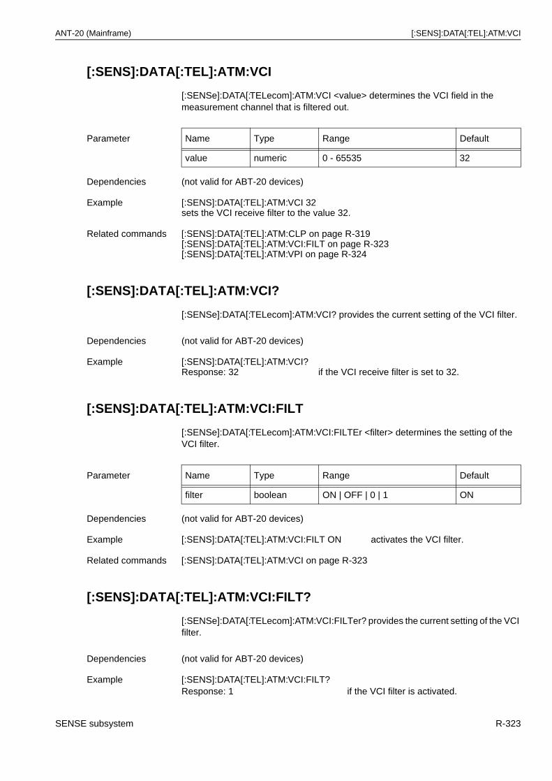
ANT-20 (Mainframe) [:SENS]:DATA[:TEL]:ATM:VCI
[:SENS]:DATA[:TEL]:ATM:VCI
[:SENSe]:DATA[:TELecom]:ATM:VCI <value> determines the VCI field in the measurement channel that is filtered out.
[:SENS]:DATA[:TEL]:ATM:VCI?
[:SENSe]:DATA[:TELecom]:ATM:VCI? provides the current setting of the VCI filter.
[:SENS]:DATA[:TEL]:ATM:VCI:FILT
[:SENSe]:DATA[:TELecom]:ATM:VCI:FILTEr <filter> determines the setting of the VCI filter.
[:SENS]:DATA[:TEL]:ATM:VCI:FILT?
[:SENSe]:DATA[:TELecom]:ATM:VCI:FILTer? provides the current setting of the VCI filter.
Parameter Name Type Range Default
value numeric 0 - 65535 32
Dependencies (not valid for ABT-20 devices)
Example [:SENS]:DATA[:TEL]:ATM:VCI 32 sets the VCI receive filter to the value 32.
Related commands [:SENS]:DATA[:TEL]:ATM:CLP on page R-319[:SENS]:DATA[:TEL]:ATM:VCI:FILT on page R-323[:SENS]:DATA[:TEL]:ATM:VPI on page R-324
Dependencies (not valid for ABT-20 devices)
Example [:SENS]:DATA[:TEL]:ATM:VCI?Response: 32 if the VCI receive filter is set to 32.
Parameter Name Type Range Default
filter boolean ON | OFF | 0 | 1 ON
Dependencies (not valid for ABT-20 devices)
Example [:SENS]:DATA[:TEL]:ATM:VCI:FILT ON activates the VCI filter.
Related commands [:SENS]:DATA[:TEL]:ATM:VCI on page R-323
Dependencies (not valid for ABT-20 devices)
Example [:SENS]:DATA[:TEL]:ATM:VCI:FILT?Response: 1 if the VCI filter is activated.
SENSE subsystem R-323
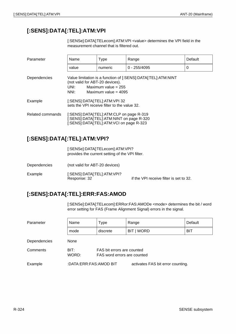
[:SENS]:DATA[:TEL]:ATM:VPI ANT-20 (Mainframe)
[:SENS]:DATA[:TEL]:ATM:VPI
[:SENSe]:DATA[:TELecom]:ATM:VPI <value> determines the VPI field in the measurement channel that is filtered out.
[:SENS]:DATA[:TEL]:ATM:VPI?
[:SENSe]:DATA[:TELecom]:ATM:VPI? provides the current setting of the VPI filter.
[:SENS]:DATA[:TEL]:ERR:FAS:AMOD
[:SENSe]:DATA[:TELecom]:ERRor:FAS:AMODe <mode> determines the bit / word error setting for FAS (Frame Alignment Signal) errors in the signal.
Parameter Name Type Range Default
value numeric 0 - 255/4095 0
Dependencies Value limitation is a function of [:SENS]:DATA[:TEL]:ATM:NINT(not valid for ABT-20 devices).UNI: Maximum value = 255NNI: Maximum value = 4095
Example [:SENS]:DATA[:TEL]:ATM:VPI 32 sets the VPI receive filter to the value 32.
Related commands [:SENS]:DATA[:TEL]:ATM:CLP on page R-319[:SENS]:DATA[:TEL]:ATM:NINT on page R-320[:SENS]:DATA[:TEL]:ATM:VCI on page R-323
Dependencies (not valid for ABT-20 devices)
Example [:SENS]:DATA[:TEL]:ATM:VPI?Response: 32 if the VPI receive filter is set to 32.
Parameter Name Type Range Default
mode discrete BIT | WORD BIT
Dependencies None
Comments BIT: FAS bit errors are countedWORD: FAS word errors are counted
Example :DATA:ERR:FAS:AMOD BIT activates FAS bit error counting.
R-324 SENSE subsystem
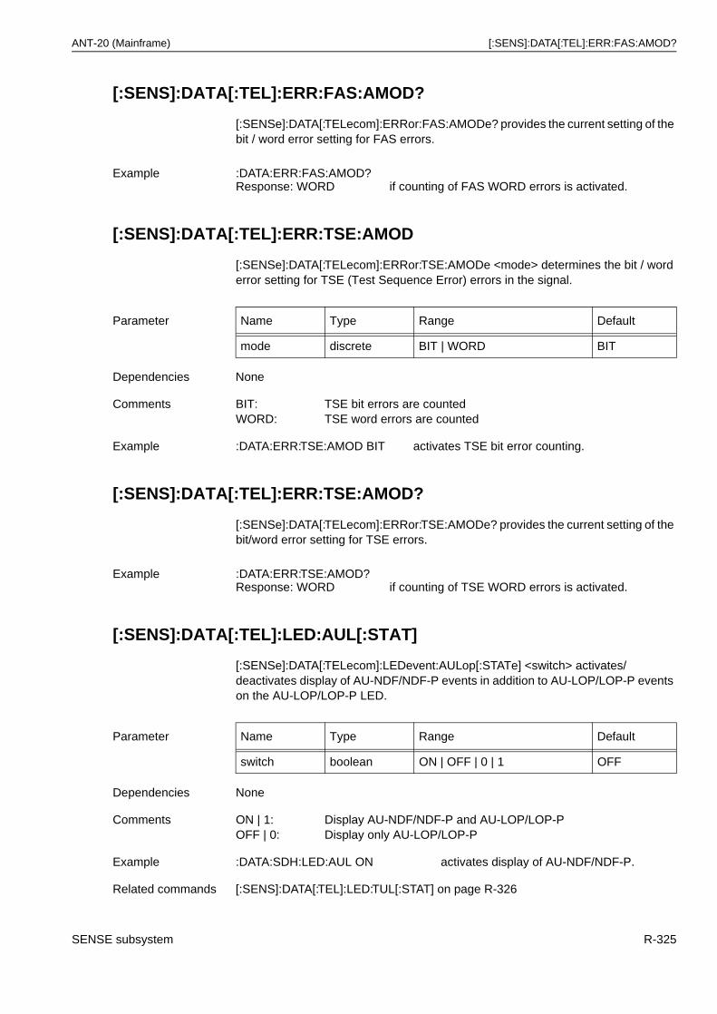
ANT-20 (Mainframe) [:SENS]:DATA[:TEL]:ERR:FAS:AMOD?
[:SENS]:DATA[:TEL]:ERR:FAS:AMOD?
[:SENSe]:DATA[:TELecom]:ERRor:FAS:AMODe? provides the current setting of the bit / word error setting for FAS errors.
[:SENS]:DATA[:TEL]:ERR:TSE:AMOD
[:SENSe]:DATA[:TELecom]:ERRor:TSE:AMODe <mode> determines the bit / word error setting for TSE (Test Sequence Error) errors in the signal.
[:SENS]:DATA[:TEL]:ERR:TSE:AMOD?
[:SENSe]:DATA[:TELecom]:ERRor:TSE:AMODe? provides the current setting of the bit/word error setting for TSE errors.
[:SENS]:DATA[:TEL]:LED:AUL[:STAT]
[:SENSe]:DATA[:TELecom]:LEDevent:AULop[:STATe] <switch> activates/deactivates display of AU-NDF/NDF-P events in addition to AU-LOP/LOP-P events on the AU-LOP/LOP-P LED.
Example :DATA:ERR:FAS:AMOD?Response: WORD if counting of FAS WORD errors is activated.
Parameter Name Type Range Default
mode discrete BIT | WORD BIT
Dependencies None
Comments BIT: TSE bit errors are countedWORD: TSE word errors are counted
Example :DATA:ERR:TSE:AMOD BIT activates TSE bit error counting.
Example :DATA:ERR:TSE:AMOD?Response: WORD if counting of TSE WORD errors is activated.
Parameter Name Type Range Default
switch boolean ON | OFF | 0 | 1 OFF
Dependencies None
Comments ON | 1: Display AU-NDF/NDF-P and AU-LOP/LOP-P OFF | 0: Display only AU-LOP/LOP-P
Example :DATA:SDH:LED:AUL ON activates display of AU-NDF/NDF-P.
Related commands [:SENS]:DATA[:TEL]:LED:TUL[:STAT] on page R-326
SENSE subsystem R-325
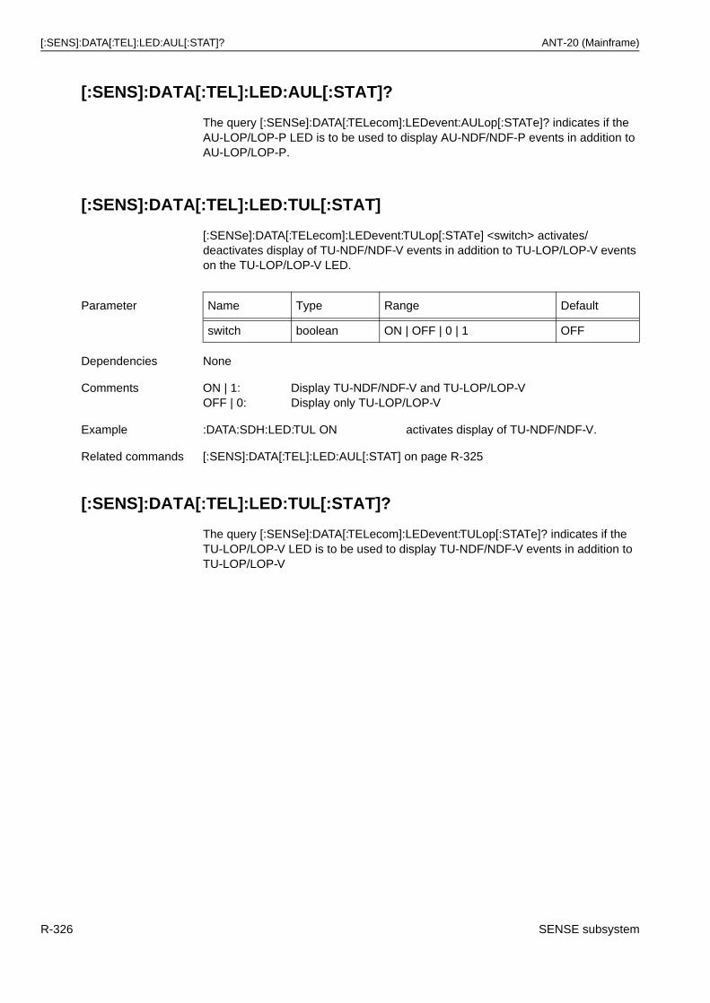
[:SENS]:DATA[:TEL]:LED:AUL[:STAT]? ANT-20 (Mainframe)
[:SENS]:DATA[:TEL]:LED:AUL[:STAT]?
The query [:SENSe]:DATA[:TELecom]:LEDevent:AULop[:STATe]? indicates if the AU-LOP/LOP-P LED is to be used to display AU-NDF/NDF-P events in addition to AU-LOP/LOP-P.
[:SENS]:DATA[:TEL]:LED:TUL[:STAT]
[:SENSe]:DATA[:TELecom]:LEDevent:TULop[:STATe] <switch> activates/deactivates display of TU-NDF/NDF-V events in addition to TU-LOP/LOP-V events on the TU-LOP/LOP-V LED.
[:SENS]:DATA[:TEL]:LED:TUL[:STAT]?
The query [:SENSe]:DATA[:TELecom]:LEDevent:TULop[:STATe]? indicates if the TU-LOP/LOP-V LED is to be used to display TU-NDF/NDF-V events in addition to TU-LOP/LOP-V
Parameter Name Type Range Default
switch boolean ON | OFF | 0 | 1 OFF
Dependencies None
Comments ON | 1: Display TU-NDF/NDF-V and TU-LOP/LOP-V OFF | 0: Display only TU-LOP/LOP-V
Example :DATA:SDH:LED:TUL ON activates display of TU-NDF/NDF-V.
Related commands [:SENS]:DATA[:TEL]:LED:AUL[:STAT] on page R-325
R-326 SENSE subsystem
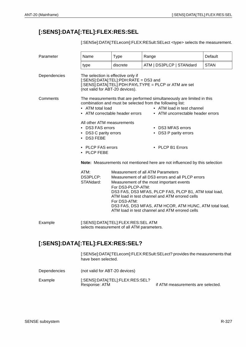
ANT-20 (Mainframe) [:SENS]:DATA[:TEL]:FLEX:RES:SEL
[:SENS]:DATA[:TEL]:FLEX:RES:SEL
[:SENSe]:DATA[:TELecom]:FLEX:RESult:SELect <type> selects the measurement.
Note: Measurements not mentioned here are not influenced by this selection
[:SENS]:DATA[:TEL]:FLEX:RES:SEL?
[:SENSe]:DATA[:TELecom]:FLEX:RESult:SELect? provides the measurements that have been selected.
Parameter Name Type Range Default
type discrete ATM | DS3PLCP | STANdard STAN
Dependencies The selection is effective only if [:SENS]:DATA[:TEL]:PDH:RATE = DS3 and [:SENS]:DATA[:TEL]:PDH:PAYL:TYPE = PLCP or ATM are set (not valid for ABT-20 devices).
Comments The measurements that are performed simultaneously are limited in this combination and must be selected from the following list:• ATM total load • ATM load in test channel• ATM correctable header errors • ATM uncorrectable header errors
All other ATM measurements• DS3 FAS errors • DS3 MFAS errors• DS3 C parity errors • DS3 P parity errors• DS3 FEBE
• PLCP FAS errors • PLCP B1 Errors• PLCP FEBE
ATM: Measurement of all ATM ParametersDS3PLCP: Measurement of all DS3 errors and all PLCP errorsSTANdard: Measurement of the most important events
For DS3-PLCP-ATM:DS3 FAS, DS3 MFAS, PLCP FAS, PLCP B1, ATM total load, ATM load in test channel and ATM errored cellsFor DS3-ATM:DS3 FAS, DS3 MFAS, ATM HCOR, ATM HUNC, ATM total load, ATM load in test channel and ATM errored cells
Example [:SENS]:DATA[:TEL]:FLEX:RES:SEL ATMselects measurement of all ATM parameters.
Dependencies (not valid for ABT-20 devices)
Example [:SENS]:DATA[:TEL]:FLEX:RES:SEL?Response: ATM if ATM measurements are selected.
SENSE subsystem R-327
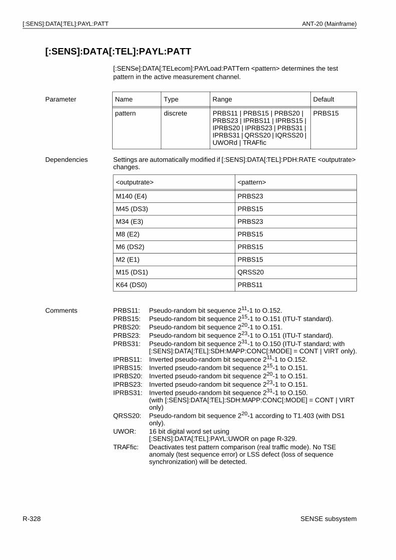
[:SENS]:DATA[:TEL]:PAYL:PATT ANT-20 (Mainframe)
[:SENS]:DATA[:TEL]:PAYL:PATT
[:SENSe]:DATA[:TELecom]:PAYLoad:PATTern <pattern> determines the test pattern in the active measurement channel.
Parameter Name Type Range Default
pattern discrete PRBS11 | PRBS15 | PRBS20 | PRBS23 | IPRBS11 | IPRBS15 | IPRBS20 | IPRBS23 | PRBS31 | IPRBS31 | QRSS20 | IQRSS20 | UWORd | TRAFfic
PRBS15
Dependencies Settings are automatically modified if [:SENS]:DATA[:TEL]:PDH:RATE <outputrate> changes.
<outputrate> <pattern>
M140 (E4) PRBS23
M45 (DS3) PRBS15
M34 (E3) PRBS23
M8 (E2) PRBS15
M6 (DS2) PRBS15
M2 (E1) PRBS15
M15 (DS1) QRSS20
K64 (DS0) PRBS11
Comments PRBS11: Pseudo-random bit sequence 211-1 to O.152.PRBS15: Pseudo-random bit sequence 215-1 to O.151 (ITU-T standard).PRBS20: Pseudo-random bit sequence 220-1 to O.151.PRBS23: Pseudo-random bit sequence 223-1 to O.151 (ITU-T standard).PRBS31: Pseudo-random bit sequence 231-1 to O.150 (ITU-T standard; with
[:SENS]:DATA[:TEL]:SDH:MAPP:CONC[:MODE] = CONT | VIRT only).IPRBS11: Inverted pseudo-random bit sequence 211-1 to O.152.IPRBS15: Inverted pseudo-random bit sequence 215-1 to O.151.IPRBS20: Inverted pseudo-random bit sequence 220-1 to O.151.IPRBS23: Inverted pseudo-random bit sequence 223-1 to O.151.IPRBS31: Inverted pseudo-random bit sequence 231-1 to O.150.
(with [:SENS]:DATA[:TEL]:SDH:MAPP:CONC[:MODE] = CONT | VIRT only)
QRSS20: Pseudo-random bit sequence 220-1 according to T1.403 (with DS1 only).
UWOR: 16 bit digital word set using[:SENS]:DATA[:TEL]:PAYL:UWOR on page R-329.
TRAFfic: Deactivates test pattern comparison (real traffic mode). No TSE anomaly (test sequence error) or LSS defect (loss of sequence synchronization) will be detected.
R-328 SENSE subsystem
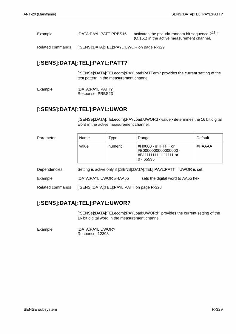
ANT-20 (Mainframe) [:SENS]:DATA[:TEL]:PAYL:PATT?
[:SENS]:DATA[:TEL]:PAYL:PATT?
[:SENSe]:DATA[:TELecom]:PAYLoad:PATTern? provides the current setting of the test pattern in the measurement channel.
[:SENS]:DATA[:TEL]:PAYL:UWOR
[:SENSe]:DATA[:TELecom]:PAYLoad:UWORd <value> determines the 16 bit digital word in the active measurement channel.
[:SENS]:DATA[:TEL]:PAYL:UWOR?
[:SENSe]:DATA[:TELecom]:PAYLoad:UWORd? provides the current setting of the 16 bit digital word in the measurement channel.
Example :DATA:PAYL:PATT PRBS15 activates the pseudo-random bit sequence 215-1(O.151) in the active measurement channel.
Related commands [:SENS]:DATA[:TEL]:PAYL:UWOR on page R-329
Example :DATA:PAYL:PATT?Response: PRBS23
Parameter Name Type Range Default
value numeric #H0000 - #HFFFF or#B0000000000000000 -#B1111111111111111 or0 - 65535
#HAAAA
Dependencies Setting is active only if [:SENS]:DATA[:TEL]:PAYL:PATT = UWOR is set.
Example :DATA:PAYL:UWOR #HAA55 sets the digital word to AA55 hex.
Related commands [:SENS]:DATA[:TEL]:PAYL:PATT on page R-328
Example :DATA:PAYL:UWOR?Response: 12398
SENSE subsystem R-329
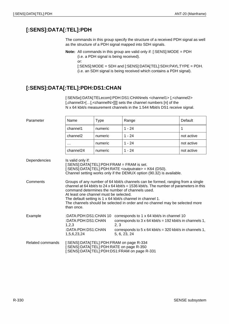
[:SENS]:DATA[:TEL]:PDH ANT-20 (Mainframe)
[:SENS]:DATA[:TEL]:PDH
The commands in this group specify the structure of a received PDH signal as well as the structure of a PDH signal mapped into SDH signals.
Note: All commands in this group are valid only if: [:SENS]:MODE = PDH(i.e. a PDH signal is being received).or:[:SENS]:MODE = SDH and [:SENS]:DATA[:TEL]:SDH:PAYL:TYPE = PDH. (i.e. an SDH signal is being received which contains a PDH signal).
[:SENS]:DATA[:TEL]:PDH:DS1:CHAN
[:SENSe]:DATA[:TELecom]:PDH:DS1:CHANnels <channel1> [,<channel2> [,channel3>[…[,<channelN>]]]] sets the channel numbers [n] of theN x 64 kbit/s measurement channels in the 1.544 Mbit/s DS1 receive signal.
Parameter Name Type Range Default
channel1 numeric 1 - 24 1
channel2 numeric 1 - 24 not active
… numeric 1 - 24 not active
channel24 numeric 1 - 24 not active
Dependencies Is valid only if:[:SENS]:DATA[:TEL]:PDH:FRAM = FRAM is set.[:SENS]:DATA[:TEL]:PDH:RATE <outputrate> = K64 (DS0).Channel setting works only if the DEMUX option (90.32) is available.
Comments Groups of any number of 64 kbit/s channels can be formed, ranging from a single channel at 64 kbit/s to 24 x 64 kbit/s = 1536 kbit/s. The number of parameters in this command determines the number of channels used.At least one channel must be selected.The default setting is 1 x 64 kbit/s channel in channel 1.The channels should be selected in order and no channel may be selected more than once.
Example :DATA:PDH:DS1:CHAN 10 corresponds to 1 x 64 kbit/s in channel 10:DATA:PDH:DS1:CHAN 1,2,3
corresponds to 3 x 64 kbit/s = 192 kbit/s in channels 1, 2, 3
:DATA:PDH:DS1:CHAN 1,5,6,23,24
corresponds to 5 x 64 kbit/s = 320 kbit/s in channels 1, 5, 6, 23, 24
Related commands [:SENS]:DATA[:TEL]:PDH:FRAM on page R-334[:SENS]:DATA[:TEL]:PDH:RATE on page R-350[:SENS]:DATA[:TEL]:PDH:DS1:FRAM on page R-331
R-330 SENSE subsystem
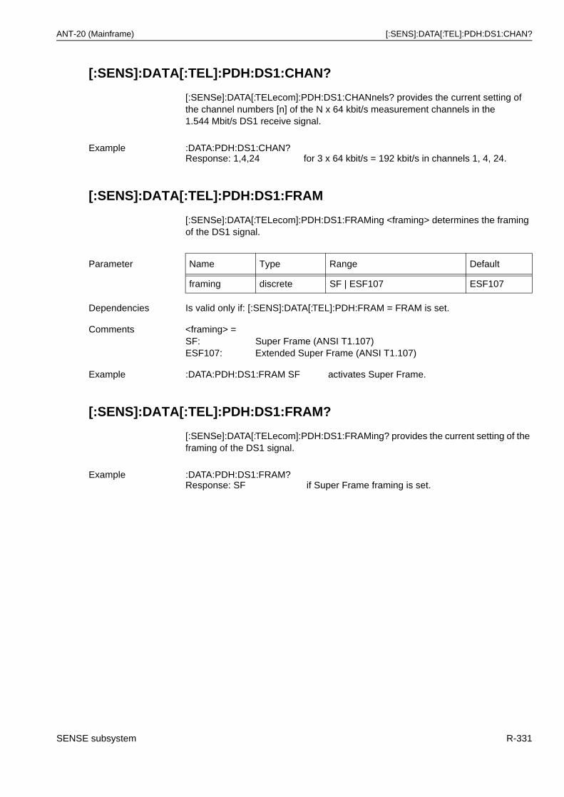
ANT-20 (Mainframe) [:SENS]:DATA[:TEL]:PDH:DS1:CHAN?
[:SENS]:DATA[:TEL]:PDH:DS1:CHAN?
[:SENSe]:DATA[:TELecom]:PDH:DS1:CHANnels? provides the current setting of the channel numbers [n] of the N x 64 kbit/s measurement channels in the1.544 Mbit/s DS1 receive signal.
[:SENS]:DATA[:TEL]:PDH:DS1:FRAM
[:SENSe]:DATA[:TELecom]:PDH:DS1:FRAMing <framing> determines the framing of the DS1 signal.
[:SENS]:DATA[:TEL]:PDH:DS1:FRAM?
[:SENSe]:DATA[:TELecom]:PDH:DS1:FRAMing? provides the current setting of the framing of the DS1 signal.
Example :DATA:PDH:DS1:CHAN?Response: 1,4,24 for 3 x 64 kbit/s = 192 kbit/s in channels 1, 4, 24.
Parameter Name Type Range Default
framing discrete SF | ESF107 ESF107
Dependencies Is valid only if: [:SENS]:DATA[:TEL]:PDH:FRAM = FRAM is set.
Comments <framing> =SF: Super Frame (ANSI T1.107)ESF107: Extended Super Frame (ANSI T1.107)
Example :DATA:PDH:DS1:FRAM SF activates Super Frame.
Example :DATA:PDH:DS1:FRAM?Response: SF if Super Frame framing is set.
SENSE subsystem R-331
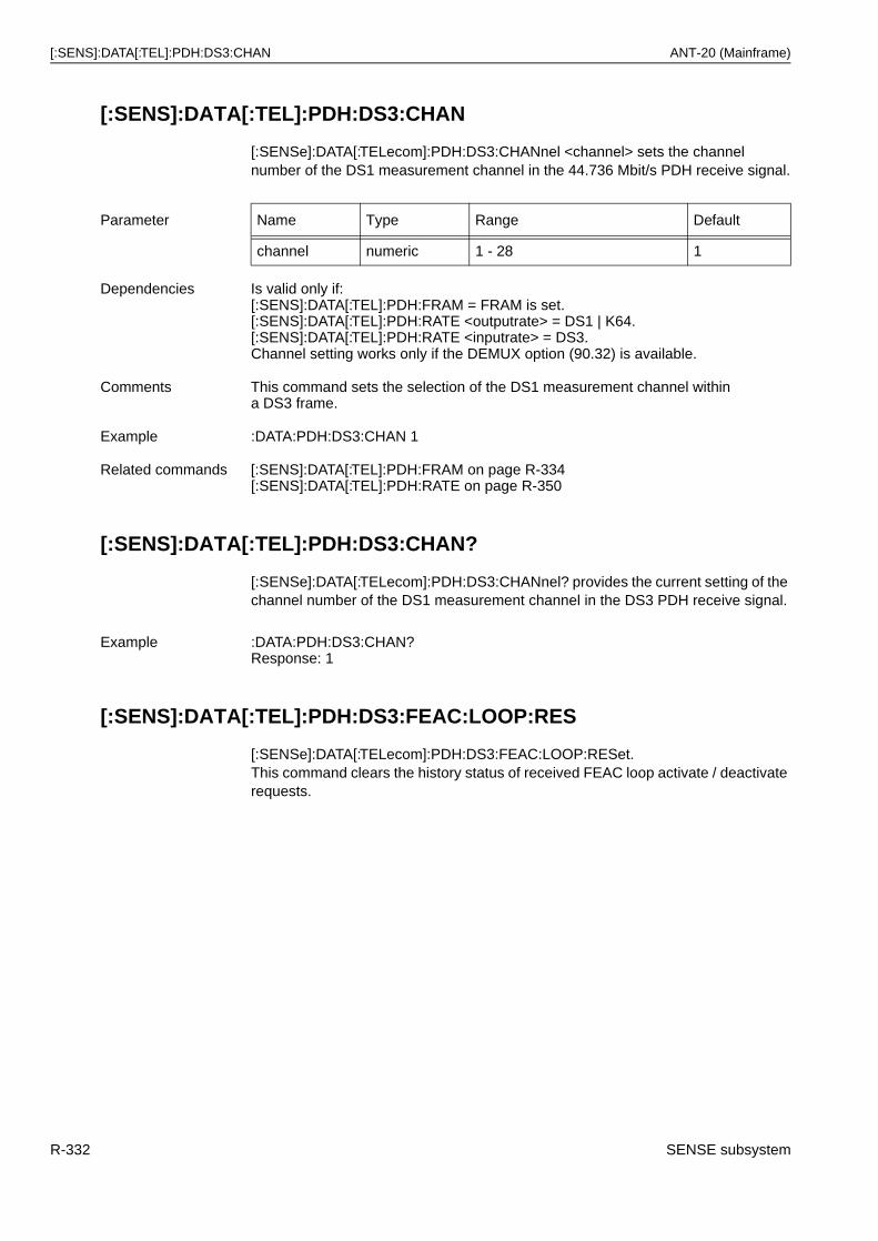
[:SENS]:DATA[:TEL]:PDH:DS3:CHAN ANT-20 (Mainframe)
[:SENS]:DATA[:TEL]:PDH:DS3:CHAN
[:SENSe]:DATA[:TELecom]:PDH:DS3:CHANnel <channel> sets the channel number of the DS1 measurement channel in the 44.736 Mbit/s PDH receive signal.
[:SENS]:DATA[:TEL]:PDH:DS3:CHAN?
[:SENSe]:DATA[:TELecom]:PDH:DS3:CHANnel? provides the current setting of the channel number of the DS1 measurement channel in the DS3 PDH receive signal.
[:SENS]:DATA[:TEL]:PDH:DS3:FEAC:LOOP:RES
[:SENSe]:DATA[:TELecom]:PDH:DS3:FEAC:LOOP:RESet.This command clears the history status of received FEAC loop activate / deactivate requests.
Parameter Name Type Range Default
channel numeric 1 - 28 1
Dependencies Is valid only if:[:SENS]:DATA[:TEL]:PDH:FRAM = FRAM is set.[:SENS]:DATA[:TEL]:PDH:RATE <outputrate> = DS1 | K64.[:SENS]:DATA[:TEL]:PDH:RATE <inputrate> = DS3.Channel setting works only if the DEMUX option (90.32) is available.
Comments This command sets the selection of the DS1 measurement channel within a DS3 frame.
Example :DATA:PDH:DS3:CHAN 1
Related commands [:SENS]:DATA[:TEL]:PDH:FRAM on page R-334[:SENS]:DATA[:TEL]:PDH:RATE on page R-350
Example :DATA:PDH:DS3:CHAN?Response: 1
R-332 SENSE subsystem
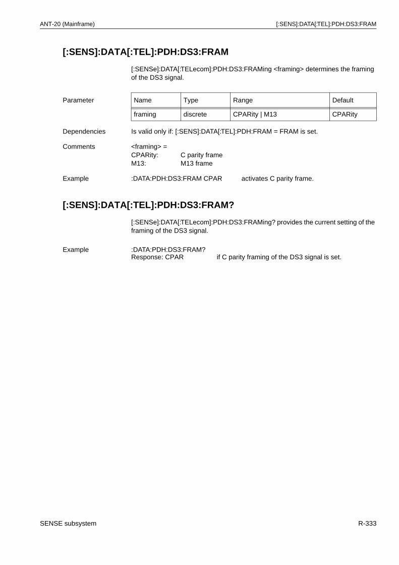
ANT-20 (Mainframe) [:SENS]:DATA[:TEL]:PDH:DS3:FRAM
[:SENS]:DATA[:TEL]:PDH:DS3:FRAM
[:SENSe]:DATA[:TELecom]:PDH:DS3:FRAMing <framing> determines the framing of the DS3 signal.
[:SENS]:DATA[:TEL]:PDH:DS3:FRAM?
[:SENSe]:DATA[:TELecom]:PDH:DS3:FRAMing? provides the current setting of the framing of the DS3 signal.
Parameter Name Type Range Default
framing discrete CPARity | M13 CPARity
Dependencies Is valid only if: [:SENS]:DATA[:TEL]:PDH:FRAM = FRAM is set.
Comments <framing> =CPARity: C parity frameM13: M13 frame
Example :DATA:PDH:DS3:FRAM CPAR activates C parity frame.
Example :DATA:PDH:DS3:FRAM?Response: CPAR if C parity framing of the DS3 signal is set.
SENSE subsystem R-333
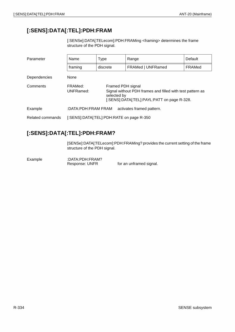
[:SENS]:DATA[:TEL]:PDH:FRAM ANT-20 (Mainframe)
[:SENS]:DATA[:TEL]:PDH:FRAM
[:SENSe]:DATA[:TELecom]:PDH:FRAMing <framing> determines the frame structure of the PDH signal.
[:SENS]:DATA[:TEL]:PDH:FRAM?
[SENSe]:DATA[:TELecom]:PDH:FRAMing? provides the current setting of the frame structure of the PDH signal.
Parameter Name Type Range Default
framing discrete FRAMed | UNFRamed FRAMed
Dependencies None
Comments FRAMed: Framed PDH signalUNFRamed: Signal without PDH frames and filled with test pattern as
selected by [:SENS]:DATA[:TEL]:PAYL:PATT on page R-328.
Example :DATA:PDH:FRAM FRAM activates framed pattern.
Related commands [:SENS]:DATA[:TEL]:PDH:RATE on page R-350
Example :DATA:PDH:FRAM?Response: UNFR for an unframed signal.
R-334 SENSE subsystem
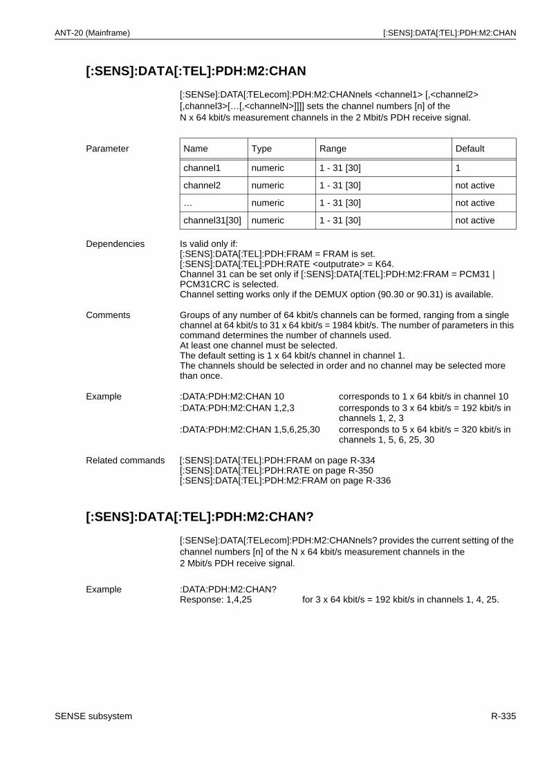
ANT-20 (Mainframe) [:SENS]:DATA[:TEL]:PDH:M2:CHAN
[:SENS]:DATA[:TEL]:PDH:M2:CHAN
[:SENSe]:DATA[:TELecom]:PDH:M2:CHANnels <channel1> [,<channel2> [,channel3>[…[,<channelN>]]]] sets the channel numbers [n] of theN x 64 kbit/s measurement channels in the 2 Mbit/s PDH receive signal.
[:SENS]:DATA[:TEL]:PDH:M2:CHAN?
[:SENSe]:DATA[:TELecom]:PDH:M2:CHANnels? provides the current setting of the channel numbers [n] of the N x 64 kbit/s measurement channels in the2 Mbit/s PDH receive signal.
Parameter Name Type Range Default
channel1 numeric 1 - 31 [30] 1
channel2 numeric 1 - 31 [30] not active
… numeric 1 - 31 [30] not active
channel31[30] numeric 1 - 31 [30] not active
Dependencies Is valid only if:[:SENS]:DATA[:TEL]:PDH:FRAM = FRAM is set.[:SENS]:DATA[:TEL]:PDH:RATE <outputrate> = K64.Channel 31 can be set only if [:SENS]:DATA[:TEL]:PDH:M2:FRAM = PCM31 | PCM31CRC is selected.Channel setting works only if the DEMUX option (90.30 or 90.31) is available.
Comments Groups of any number of 64 kbit/s channels can be formed, ranging from a single channel at 64 kbit/s to 31 x 64 kbit/s = 1984 kbit/s. The number of parameters in this command determines the number of channels used.At least one channel must be selected.The default setting is 1 x 64 kbit/s channel in channel 1.The channels should be selected in order and no channel may be selected more than once.
Example :DATA:PDH:M2:CHAN 10 corresponds to 1 x 64 kbit/s in channel 10:DATA:PDH:M2:CHAN 1,2,3 corresponds to 3 x 64 kbit/s = 192 kbit/s in
channels 1, 2, 3:DATA:PDH:M2:CHAN 1,5,6,25,30 corresponds to 5 x 64 kbit/s = 320 kbit/s in
channels 1, 5, 6, 25, 30
Related commands [:SENS]:DATA[:TEL]:PDH:FRAM on page R-334[:SENS]:DATA[:TEL]:PDH:RATE on page R-350[:SENS]:DATA[:TEL]:PDH:M2:FRAM on page R-336
Example :DATA:PDH:M2:CHAN?Response: 1,4,25 for 3 x 64 kbit/s = 192 kbit/s in channels 1, 4, 25.
SENSE subsystem R-335
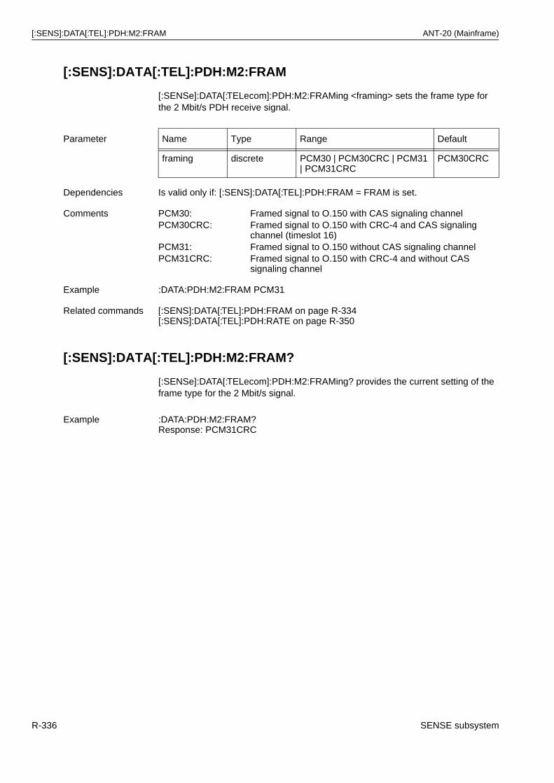
[:SENS]:DATA[:TEL]:PDH:M2:FRAM ANT-20 (Mainframe)
[:SENS]:DATA[:TEL]:PDH:M2:FRAM
[:SENSe]:DATA[:TELecom]:PDH:M2:FRAMing <framing> sets the frame type for the 2 Mbit/s PDH receive signal.
[:SENS]:DATA[:TEL]:PDH:M2:FRAM?
[:SENSe]:DATA[:TELecom]:PDH:M2:FRAMing? provides the current setting of the frame type for the 2 Mbit/s signal.
Parameter Name Type Range Default
framing discrete PCM30 | PCM30CRC | PCM31 | PCM31CRC
PCM30CRC
Dependencies Is valid only if: [:SENS]:DATA[:TEL]:PDH:FRAM = FRAM is set.
Comments PCM30: Framed signal to O.150 with CAS signaling channelPCM30CRC: Framed signal to O.150 with CRC-4 and CAS signaling
channel (timeslot 16)PCM31: Framed signal to O.150 without CAS signaling channelPCM31CRC: Framed signal to O.150 with CRC-4 and without CAS
signaling channel
Example :DATA:PDH:M2:FRAM PCM31
Related commands [:SENS]:DATA[:TEL]:PDH:FRAM on page R-334[:SENS]:DATA[:TEL]:PDH:RATE on page R-350
Example :DATA:PDH:M2:FRAM?Response: PCM31CRC
R-336 SENSE subsystem
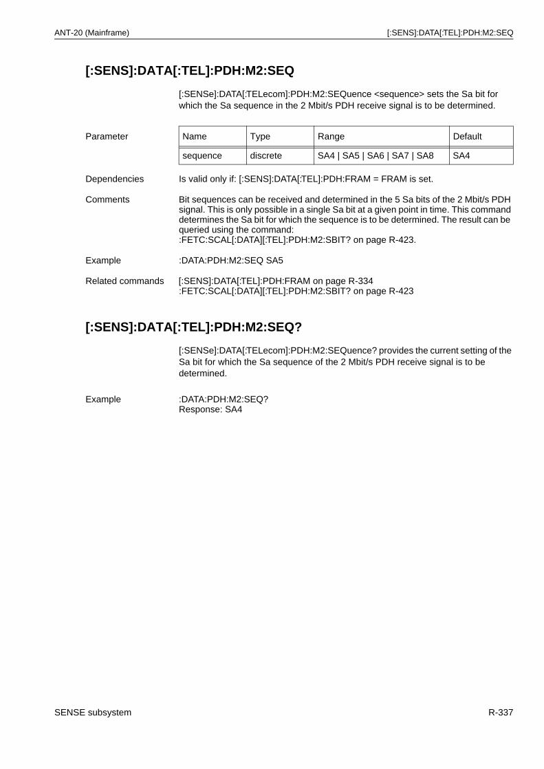
ANT-20 (Mainframe) [:SENS]:DATA[:TEL]:PDH:M2:SEQ
[:SENS]:DATA[:TEL]:PDH:M2:SEQ
[:SENSe]:DATA[:TELecom]:PDH:M2:SEQuence <sequence> sets the Sa bit for which the Sa sequence in the 2 Mbit/s PDH receive signal is to be determined.
[:SENS]:DATA[:TEL]:PDH:M2:SEQ?
[:SENSe]:DATA[:TELecom]:PDH:M2:SEQuence? provides the current setting of the Sa bit for which the Sa sequence of the 2 Mbit/s PDH receive signal is to be determined.
Parameter Name Type Range Default
sequence discrete SA4 | SA5 | SA6 | SA7 | SA8 SA4
Dependencies Is valid only if: [:SENS]:DATA[:TEL]:PDH:FRAM = FRAM is set.
Comments Bit sequences can be received and determined in the 5 Sa bits of the 2 Mbit/s PDH signal. This is only possible in a single Sa bit at a given point in time. This command determines the Sa bit for which the sequence is to be determined. The result can be queried using the command::FETC:SCAL[:DATA][:TEL]:PDH:M2:SBIT? on page R-423.
Example :DATA:PDH:M2:SEQ SA5
Related commands [:SENS]:DATA[:TEL]:PDH:FRAM on page R-334:FETC:SCAL[:DATA][:TEL]:PDH:M2:SBIT? on page R-423
Example :DATA:PDH:M2:SEQ?Response: SA4
SENSE subsystem R-337
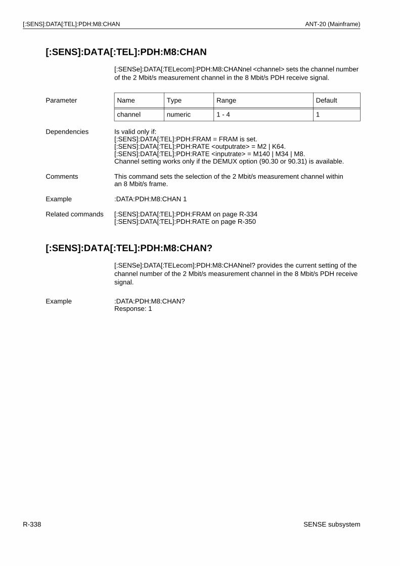
[:SENS]:DATA[:TEL]:PDH:M8:CHAN ANT-20 (Mainframe)
[:SENS]:DATA[:TEL]:PDH:M8:CHAN
[:SENSe]:DATA[:TELecom]:PDH:M8:CHANnel <channel> sets the channel number of the 2 Mbit/s measurement channel in the 8 Mbit/s PDH receive signal.
[:SENS]:DATA[:TEL]:PDH:M8:CHAN?
[:SENSe]:DATA[:TELecom]:PDH:M8:CHANnel? provides the current setting of the channel number of the 2 Mbit/s measurement channel in the 8 Mbit/s PDH receive signal.
Parameter Name Type Range Default
channel numeric 1 - 4 1
Dependencies Is valid only if:[:SENS]:DATA[:TEL]:PDH:FRAM = FRAM is set.[:SENS]:DATA[:TEL]:PDH:RATE <outputrate> = M2 | K64.[:SENS]:DATA[:TEL]:PDH:RATE <inputrate> = M140 | M34 | M8.Channel setting works only if the DEMUX option (90.30 or 90.31) is available.
Comments This command sets the selection of the 2 Mbit/s measurement channel within an 8 Mbit/s frame.
Example :DATA:PDH:M8:CHAN 1
Related commands [:SENS]:DATA[:TEL]:PDH:FRAM on page R-334[:SENS]:DATA[:TEL]:PDH:RATE on page R-350
Example :DATA:PDH:M8:CHAN?Response: 1
R-338 SENSE subsystem
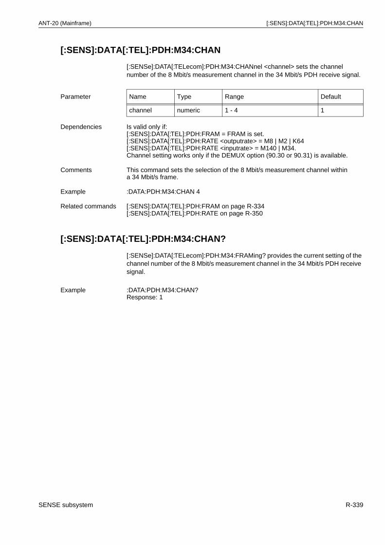
ANT-20 (Mainframe) [:SENS]:DATA[:TEL]:PDH:M34:CHAN
[:SENS]:DATA[:TEL]:PDH:M34:CHAN
[:SENSe]:DATA[:TELecom]:PDH:M34:CHANnel <channel> sets the channel number of the 8 Mbit/s measurement channel in the 34 Mbit/s PDH receive signal.
[:SENS]:DATA[:TEL]:PDH:M34:CHAN?
[:SENSe]:DATA[:TELecom]:PDH:M34:FRAMing? provides the current setting of the channel number of the 8 Mbit/s measurement channel in the 34 Mbit/s PDH receive signal.
Parameter Name Type Range Default
channel numeric 1 - 4 1
Dependencies Is valid only if:[:SENS]:DATA[:TEL]:PDH:FRAM = FRAM is set.[:SENS]:DATA[:TEL]:PDH:RATE <outputrate> = M8 | M2 | K64[:SENS]:DATA[:TEL]:PDH:RATE <inputrate> = M140 | M34.Channel setting works only if the DEMUX option (90.30 or 90.31) is available.
Comments This command sets the selection of the 8 Mbit/s measurement channel within a 34 Mbit/s frame.
Example :DATA:PDH:M34:CHAN 4
Related commands [:SENS]:DATA[:TEL]:PDH:FRAM on page R-334[:SENS]:DATA[:TEL]:PDH:RATE on page R-350
Example :DATA:PDH:M34:CHAN?Response: 1
SENSE subsystem R-339
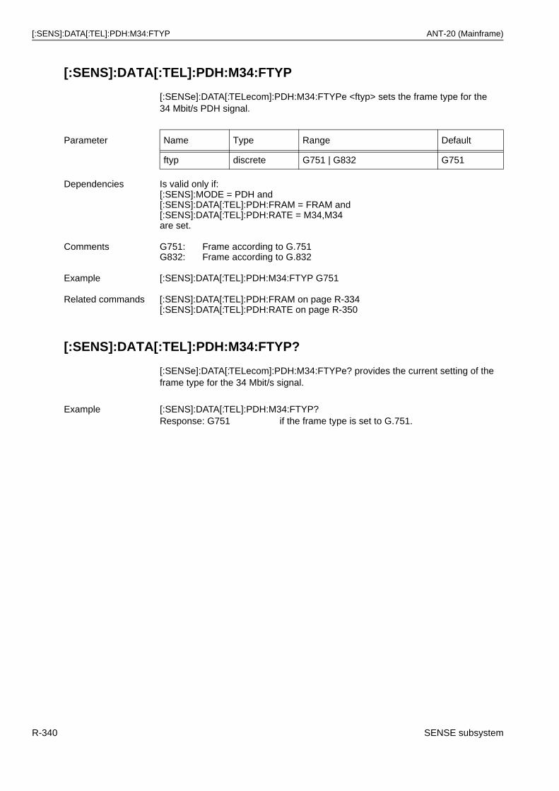
[:SENS]:DATA[:TEL]:PDH:M34:FTYP ANT-20 (Mainframe)
[:SENS]:DATA[:TEL]:PDH:M34:FTYP
[:SENSe]:DATA[:TELecom]:PDH:M34:FTYPe <ftyp> sets the frame type for the 34 Mbit/s PDH signal.
[:SENS]:DATA[:TEL]:PDH:M34:FTYP?
[:SENSe]:DATA[:TELecom]:PDH:M34:FTYPe? provides the current setting of the frame type for the 34 Mbit/s signal.
Parameter Name Type Range Default
ftyp discrete G751 | G832 G751
Dependencies Is valid only if:[:SENS]:MODE = PDH and[:SENS]:DATA[:TEL]:PDH:FRAM = FRAM and[:SENS]:DATA[:TEL]:PDH:RATE = M34,M34are set.
Comments G751:G832:
Frame according to G.751Frame according to G.832
Example [:SENS]:DATA[:TEL]:PDH:M34:FTYP G751
Related commands [:SENS]:DATA[:TEL]:PDH:FRAM on page R-334[:SENS]:DATA[:TEL]:PDH:RATE on page R-350
Example [:SENS]:DATA[:TEL]:PDH:M34:FTYP?Response: G751 if the frame type is set to G.751.
R-340 SENSE subsystem
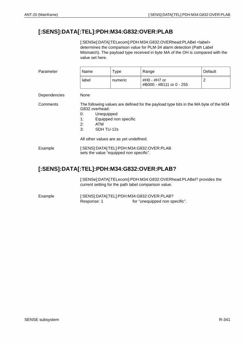
ANT-20 (Mainframe) [:SENS]:DATA[:TEL]:PDH:M34:G832:OVER:PLAB
[:SENS]:DATA[:TEL]:PDH:M34:G832:OVER:PLAB
[:SENSe]:DATA[:TELecom]:PDH:M34:G832:OVERhead:PLABel <label> determines the comparison value for PLM-34 alarm detection (Path Label Mismatch). The payload type received in byte MA of the OH is compared with the value set here.
[:SENS]:DATA[:TEL]:PDH:M34:G832:OVER:PLAB?
[:SENSe]:DATA[:TELecom]:PDH:M34:G832:OVERhead:PLABel? provides the current setting for the path label comparison value.
Parameter Name Type Range Default
label numeric #H0 - #H7 or#B000 - #B111 or 0 - 255
2
Dependencies None
Comments The following values are defined for the payload type bits in the MA byte of the M34 G832 overhead:0: Unequipped1: Equipped non specific2: ATM3: SDH TU-12s
All other values are as yet undefined.
Example [:SENS]:DATA[:TEL]:PDH:M34:G832:OVER:PLAB sets the value “equipped non specific”.
Example [:SENS]:DATA[:TEL]:PDH:M34:G832:OVER:PLAB?Response: 1 for “unequipped non specific”.
SENSE subsystem R-341
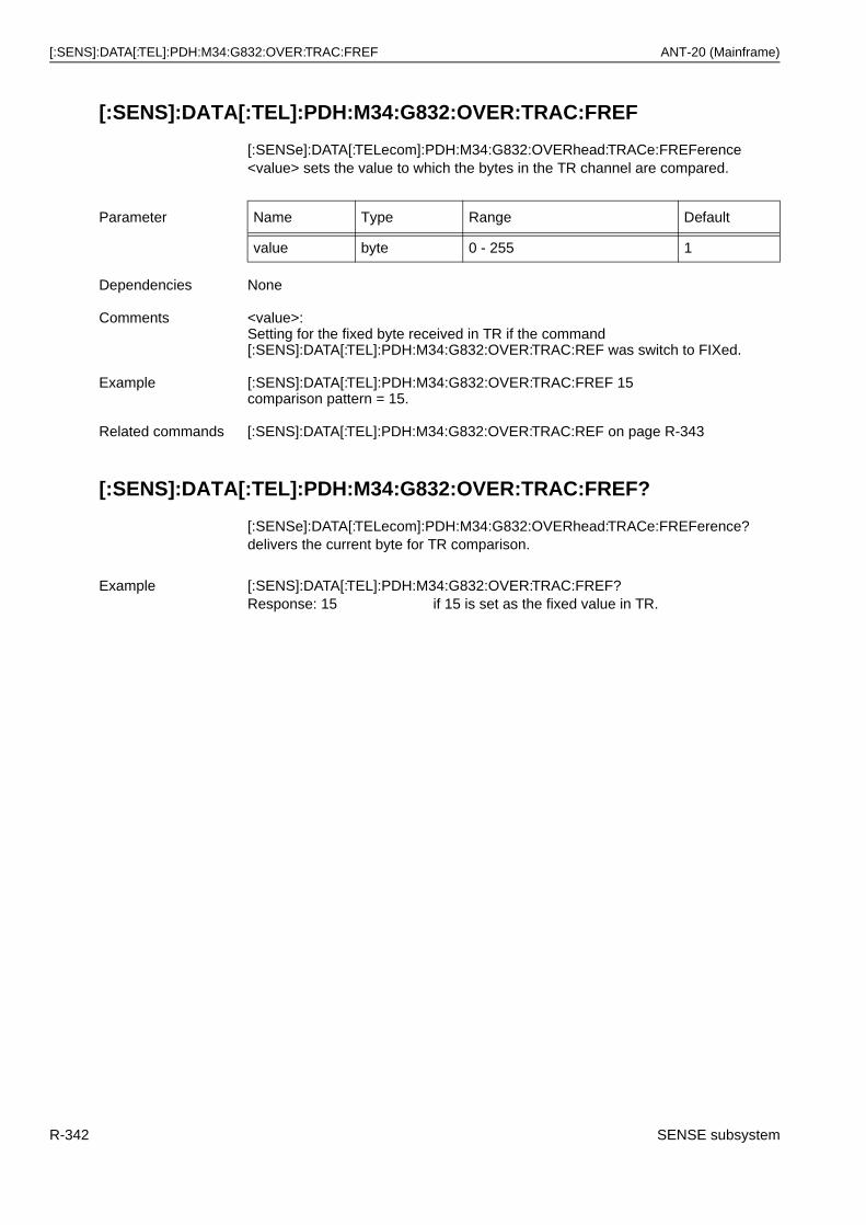
[:SENS]:DATA[:TEL]:PDH:M34:G832:OVER:TRAC:FREF ANT-20 (Mainframe)
[:SENS]:DATA[:TEL]:PDH:M34:G832:OVER:TRAC:FREF
[:SENSe]:DATA[:TELecom]:PDH:M34:G832:OVERhead:TRACe:FREFerence <value> sets the value to which the bytes in the TR channel are compared.
[:SENS]:DATA[:TEL]:PDH:M34:G832:OVER:TRAC:FREF?
[:SENSe]:DATA[:TELecom]:PDH:M34:G832:OVERhead:TRACe:FREFerence? delivers the current byte for TR comparison.
Parameter Name Type Range Default
value byte 0 - 255 1
Dependencies None
Comments <value>:Setting for the fixed byte received in TR if the command[:SENS]:DATA[:TEL]:PDH:M34:G832:OVER:TRAC:REF was switch to FIXed.
Example [:SENS]:DATA[:TEL]:PDH:M34:G832:OVER:TRAC:FREF 15comparison pattern = 15.
Related commands [:SENS]:DATA[:TEL]:PDH:M34:G832:OVER:TRAC:REF on page R-343
Example [:SENS]:DATA[:TEL]:PDH:M34:G832:OVER:TRAC:FREF?Response: 15 if 15 is set as the fixed value in TR.
R-342 SENSE subsystem
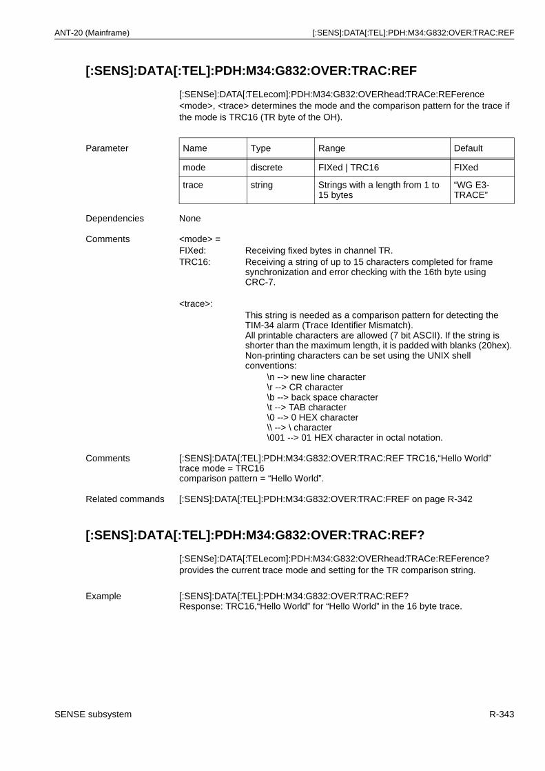
ANT-20 (Mainframe) [:SENS]:DATA[:TEL]:PDH:M34:G832:OVER:TRAC:REF
[:SENS]:DATA[:TEL]:PDH:M34:G832:OVER:TRAC:REF
[:SENSe]:DATA[:TELecom]:PDH:M34:G832:OVERhead:TRACe:REFerence <mode>, <trace> determines the mode and the comparison pattern for the trace if the mode is TRC16 (TR byte of the OH).
[:SENS]:DATA[:TEL]:PDH:M34:G832:OVER:TRAC:REF?
[:SENSe]:DATA[:TELecom]:PDH:M34:G832:OVERhead:TRACe:REFerence? provides the current trace mode and setting for the TR comparison string.
Parameter Name Type Range Default
mode discrete FIXed | TRC16 FIXed
trace string Strings with a length from 1 to 15 bytes
“WG E3-TRACE”
Dependencies None
Comments <mode> =FIXed: Receiving fixed bytes in channel TR.TRC16: Receiving a string of up to 15 characters completed for frame
synchronization and error checking with the 16th byte using CRC-7.
<trace>:This string is needed as a comparison pattern for detecting the TIM-34 alarm (Trace Identifier Mismatch).All printable characters are allowed (7 bit ASCII). If the string isshorter than the maximum length, it is padded with blanks (20hex). Non-printing characters can be set using the UNIX shell conventions:
\n --> new line character\r --> CR character\b --> back space character\t --> TAB character\0 --> 0 HEX character\\ --> \ character\001 --> 01 HEX character in octal notation.
Comments [:SENS]:DATA[:TEL]:PDH:M34:G832:OVER:TRAC:REF TRC16,“Hello World”trace mode = TRC16comparison pattern = “Hello World”.
Related commands [:SENS]:DATA[:TEL]:PDH:M34:G832:OVER:TRAC:FREF on page R-342
Example [:SENS]:DATA[:TEL]:PDH:M34:G832:OVER:TRAC:REF?Response: TRC16,“Hello World” for “Hello World” in the 16 byte trace.
SENSE subsystem R-343
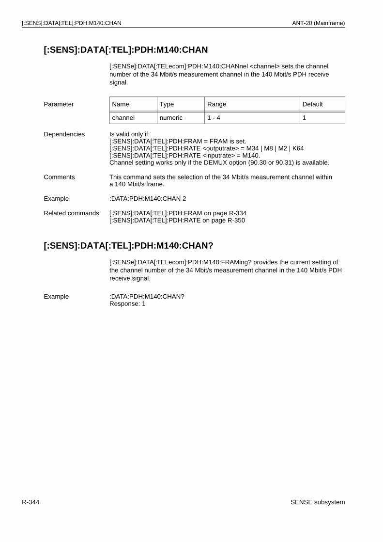
[:SENS]:DATA[:TEL]:PDH:M140:CHAN ANT-20 (Mainframe)
[:SENS]:DATA[:TEL]:PDH:M140:CHAN
[:SENSe]:DATA[:TELecom]:PDH:M140:CHANnel <channel> sets the channel number of the 34 Mbit/s measurement channel in the 140 Mbit/s PDH receive signal.
[:SENS]:DATA[:TEL]:PDH:M140:CHAN?
[:SENSe]:DATA[:TELecom]:PDH:M140:FRAMing? provides the current setting of the channel number of the 34 Mbit/s measurement channel in the 140 Mbit/s PDH receive signal.
Parameter Name Type Range Default
channel numeric 1 - 4 1
Dependencies Is valid only if:[:SENS]:DATA[:TEL]:PDH:FRAM = FRAM is set.[:SENS]:DATA[:TEL]:PDH:RATE <outputrate> = M34 | M8 | M2 | K64[:SENS]:DATA[:TEL]:PDH:RATE <inputrate> = M140.Channel setting works only if the DEMUX option (90.30 or 90.31) is available.
Comments This command sets the selection of the 34 Mbit/s measurement channel within a 140 Mbit/s frame.
Example :DATA:PDH:M140:CHAN 2
Related commands [:SENS]:DATA[:TEL]:PDH:FRAM on page R-334[:SENS]:DATA[:TEL]:PDH:RATE on page R-350
Example :DATA:PDH:M140:CHAN?Response: 1
R-344 SENSE subsystem
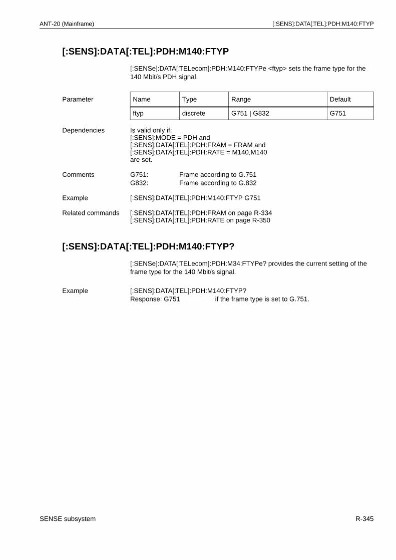
ANT-20 (Mainframe) [:SENS]:DATA[:TEL]:PDH:M140:FTYP
[:SENS]:DATA[:TEL]:PDH:M140:FTYP
[:SENSe]:DATA[:TELecom]:PDH:M140:FTYPe <ftyp> sets the frame type for the 140 Mbit/s PDH signal.
[:SENS]:DATA[:TEL]:PDH:M140:FTYP?
[:SENSe]:DATA[:TELecom]:PDH:M34:FTYPe? provides the current setting of the frame type for the 140 Mbit/s signal.
Parameter Name Type Range Default
ftyp discrete G751 | G832 G751
Dependencies Is valid only if:[:SENS]:MODE = PDH and[:SENS]:DATA[:TEL]:PDH:FRAM = FRAM and[:SENS]:DATA[:TEL]:PDH:RATE = M140,M140are set.
Comments G751: Frame according to G.751G832: Frame according to G.832
Example [:SENS]:DATA[:TEL]:PDH:M140:FTYP G751
Related commands [:SENS]:DATA[:TEL]:PDH:FRAM on page R-334[:SENS]:DATA[:TEL]:PDH:RATE on page R-350
Example [:SENS]:DATA[:TEL]:PDH:M140:FTYP?Response: G751 if the frame type is set to G.751.
SENSE subsystem R-345
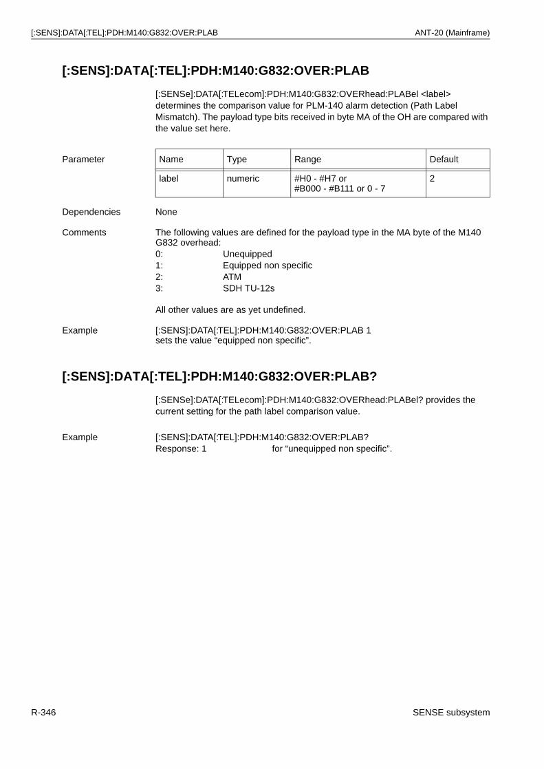
[:SENS]:DATA[:TEL]:PDH:M140:G832:OVER:PLAB ANT-20 (Mainframe)
[:SENS]:DATA[:TEL]:PDH:M140:G832:OVER:PLAB
[:SENSe]:DATA[:TELecom]:PDH:M140:G832:OVERhead:PLABel <label> determines the comparison value for PLM-140 alarm detection (Path Label Mismatch). The payload type bits received in byte MA of the OH are compared with the value set here.
[:SENS]:DATA[:TEL]:PDH:M140:G832:OVER:PLAB?
[:SENSe]:DATA[:TELecom]:PDH:M140:G832:OVERhead:PLABel? provides the current setting for the path label comparison value.
Parameter Name Type Range Default
label numeric #H0 - #H7 or#B000 - #B111 or 0 - 7
2
Dependencies None
Comments The following values are defined for the payload type in the MA byte of the M140 G832 overhead:0: Unequipped1: Equipped non specific2: ATM3: SDH TU-12s
All other values are as yet undefined.
Example [:SENS]:DATA[:TEL]:PDH:M140:G832:OVER:PLAB 1sets the value “equipped non specific”.
Example [:SENS]:DATA[:TEL]:PDH:M140:G832:OVER:PLAB?Response: 1 for “unequipped non specific”.
R-346 SENSE subsystem
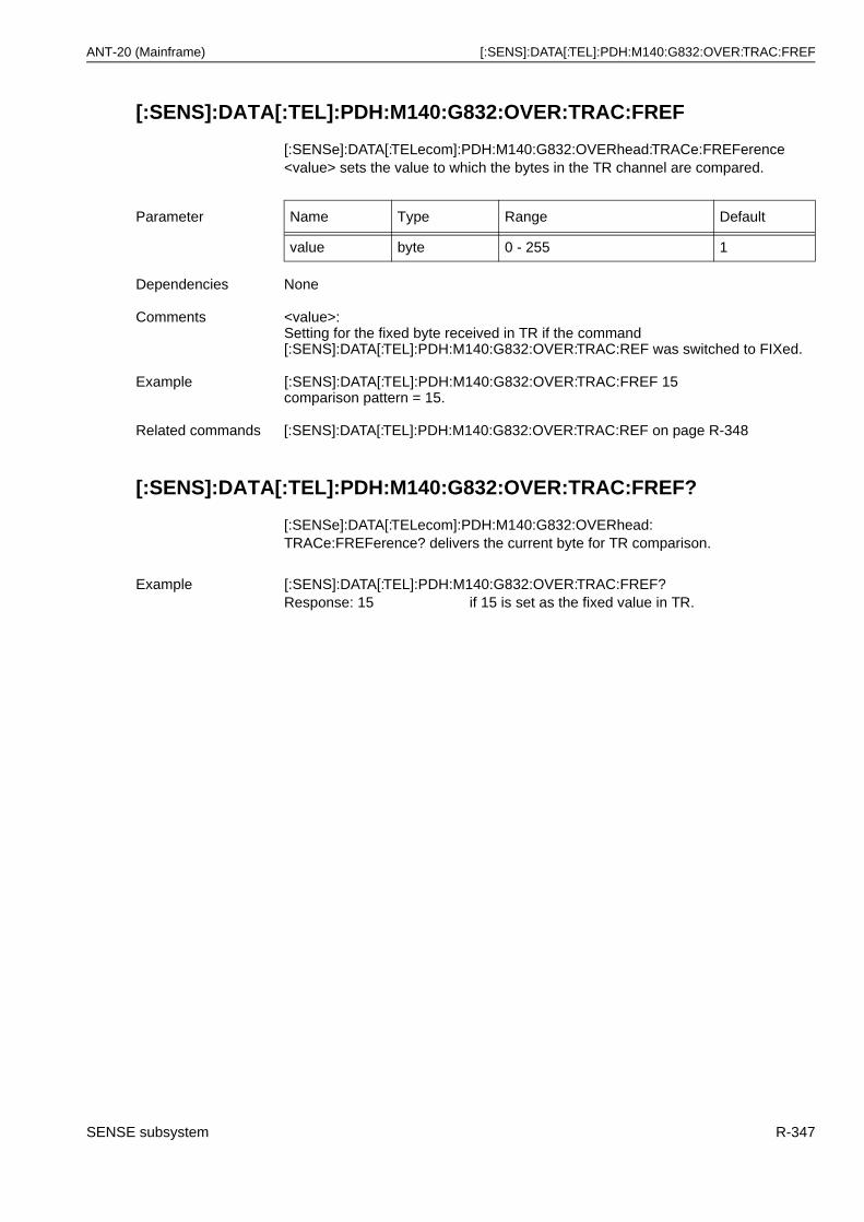
ANT-20 (Mainframe) [:SENS]:DATA[:TEL]:PDH:M140:G832:OVER:TRAC:FREF
[:SENS]:DATA[:TEL]:PDH:M140:G832:OVER:TRAC:FREF
[:SENSe]:DATA[:TELecom]:PDH:M140:G832:OVERhead:TRACe:FREFerence <value> sets the value to which the bytes in the TR channel are compared.
[:SENS]:DATA[:TEL]:PDH:M140:G832:OVER:TRAC:FREF?
[:SENSe]:DATA[:TELecom]:PDH:M140:G832:OVERhead:TRACe:FREFerence? delivers the current byte for TR comparison.
Parameter Name Type Range Default
value byte 0 - 255 1
Dependencies None
Comments <value>:Setting for the fixed byte received in TR if the command[:SENS]:DATA[:TEL]:PDH:M140:G832:OVER:TRAC:REF was switched to FIXed.
Example [:SENS]:DATA[:TEL]:PDH:M140:G832:OVER:TRAC:FREF 15comparison pattern = 15.
Related commands [:SENS]:DATA[:TEL]:PDH:M140:G832:OVER:TRAC:REF on page R-348
Example [:SENS]:DATA[:TEL]:PDH:M140:G832:OVER:TRAC:FREF?Response: 15 if 15 is set as the fixed value in TR.
SENSE subsystem R-347
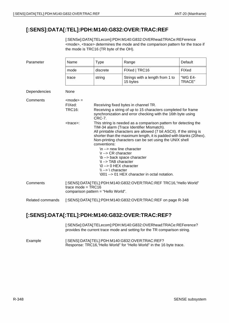
[:SENS]:DATA[:TEL]:PDH:M140:G832:OVER:TRAC:REF ANT-20 (Mainframe)
[:SENS]:DATA[:TEL]:PDH:M140:G832:OVER:TRAC:REF
[:SENSe]:DATA[:TELecom]:PDH:M140:G832:OVERhead:TRACe:REFerence <mode>, <trace> determines the mode and the comparison pattern for the trace if the mode is TRC16 (TR byte of the OH).
[:SENS]:DATA[:TEL]:PDH:M140:G832:OVER:TRAC:REF?
[:SENSe]:DATA[:TELecom]:PDH:M140:G832:OVERhead:TRACe:REFerence? provides the current trace mode and setting for the TR comparison string.
Parameter Name Type Range Default
mode discrete FIXed | TRC16 FIXed
trace string Strings with a length from 1 to 15 bytes
“WG E4-TRACE”
Dependencies None
Comments <mode> =FIXed: Receiving fixed bytes in channel TR.TRC16: Receiving a string of up to 15 characters completed for frame
synchronization and error checking with the 16th byte using CRC-7.
<trace>: This string is needed as a comparison pattern for detecting the TIM-34 alarm (Trace Identifier Mismatch).All printable characters are allowed (7 bit ASCII). If the string is shorter than the maximum length, it is padded with blanks (20hex). Non-printing characters can be set using the UNIX shell conventions:
\n --> new line character\r --> CR character\b --> back space character\t --> TAB character\0 --> 0 HEX character\\ --> \ character\001 --> 01 HEX character in octal notation.
Comments [:SENS]:DATA[:TEL]:PDH:M140:G832:OVER:TRAC:REF TRC16,“Hello World”trace mode = TRC16comparison pattern = “Hello World”.
Related commands [:SENS]:DATA[:TEL]:PDH:M140:G832:OVER:TRAC:REF on page R-348
Example [:SENS]:DATA[:TEL]:PDH:M140:G832:OVER:TRAC:REF?Response: TRC16,“Hello World” for “Hello World” in the 16 byte trace.
R-348 SENSE subsystem
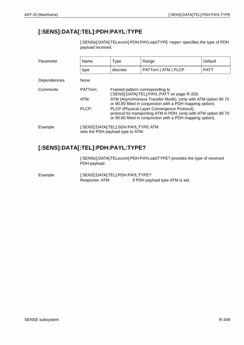
ANT-20 (Mainframe) [:SENS]:DATA[:TEL]:PDH:PAYL:TYPE
[:SENS]:DATA[:TEL]:PDH:PAYL:TYPE
[:SENSe]:DATA[:TELecom]:PDH:PAYLoad:TYPE <type> specifies the type of PDH payload received.
[:SENS]:DATA[:TEL]:PDH:PAYL:TYPE?
[:SENSe]:DATA[:TELecom]:PDH:PAYLoad:TYPE? provides the type of received PDH payload.
Parameter Name Type Range Default
type discrete PATTern | ATM | PLCP PATT
Dependencies None
Comments PATTern: Framed pattern corresponding to[:SENS]:DATA[:TEL]:PAYL:PATT on page R-328.
ATM: ATM (Asynchronous Transfer Mode), (only with ATM option 90.70 or 90.80 fitted in conjunction with a PDH mapping option).
PLCP: PLCP (Physical Layer Convergence Protocol), protocol for transporting ATM in PDH, (only with ATM option 90.70 or 90.80 fitted in conjunction with a PDH mapping option).
Example [:SENS]:DATA[:TEL]:SDH:PAYL:TYPE ATM sets the PDH payload type to ATM.
Example [:SENS]:DATA[:TEL]:PDH:PAYL:TYPE?Response: ATM if PDH payload type ATM is set.
SENSE subsystem R-349
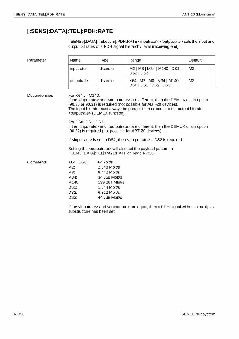
[:SENS]:DATA[:TEL]:PDH:RATE ANT-20 (Mainframe)
[:SENS]:DATA[:TEL]:PDH:RATE
[:SENSe]:DATA[:TELecom]:PDH:RATE <inputrate>, <outputrate> sets the input and output bit rates of a PDH signal hierarchy level (receiving end).
Parameter Name Type Range Default
inputrate discrete M2 | M8 | M34 | M140 | DS1 | DS2 | DS3
M2
outputrate discrete K64 | M2 | M8 | M34 | M140 | DS0 | DS1 | DS2 | DS3
M2
Dependencies For K64 … M140:If the <inputrate> and <outputrate> are different, then the DEMUX chain option (90.30 or 90.31) is required (not possible for ABT-20 devices).The input bit rate must always be greater than or equal to the output bit rate <outputrate> (DEMUX function).
For DS0, DS1, DS3:If the <inputrate> and <outputrate> are different, then the DEMUX chain option (90.32) is required (not possible for ABT-20 devices).
If <inputrate> is set to DS2, then <outputrate> = DS2 is required.
Setting the <outputrate> will also set the payload pattern in [:SENS]:DATA[:TEL]:PAYL:PATT on page R-328.
Comments K64 | DS0: 64 kbit/sM2: 2.048 Mbit/sM8: 8.442 Mbit/sM34: 34.368 Mbit/sM140: 139.264 Mbit/sDS1: 1.544 Mbit/sDS2: 6.312 Mbit/sDS3: 44.738 Mbit/s
If the <inputrate> and <outputrate> are equal, then a PDH signal without a multiplex substructure has been set.
R-350 SENSE subsystem
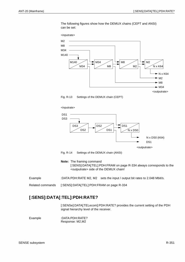
ANT-20 (Mainframe) [:SENS]:DATA[:TEL]:PDH:RATE?
The following figures show how the DEMUX chains (CEPT and ANSI) can be set:
Fig. R-13 Settings of the DEMUX chain (CEPT)
Fig. R-14 Settings of the DEMUX chain (ANSI)
Note: The framing command[:SENS]:DATA[:TEL]:PDH:FRAM on page R-334 always corresponds to the <outputrate> side of the DEMUX chain!
[:SENS]:DATA[:TEL]:PDH:RATE?
[:SENSe]:DATA[:TELecom]:PDH:RATE? provides the current setting of the PDH signal hierarchy level of the receiver.
Example :DATA:PDH:RATE M2, M2 sets the input / output bit rates to 2.048 Mbit/s.
Related commands [:SENS]:DATA[:TEL]:PDH:FRAM on page R-334
Example :DATA:PDH:RATE?Response: M2,M2
M140
M34
M34
M8
M8
M2
M2
N x K64
M140
M2
M8
M34
<outputrate>
M34
N x K64
M2
M8
<inputrate>
DS3
DS2
DS2
DS1
DS3
<inputrate>
<outputrate>
DS1
DS1
N x DS0
DS1
N x DS0 (K64)
SENSE subsystem R-351
[:SENS]:DATA[:TEL]:SDH ANT-20 (Mainframe)
[:SENS]:DATA[:TEL]:SDH
The commands in this group specify the structure of a received SDH/SONET signal.
Note: All commands in this group are valid only if [:SENS]:MODE = SDH.
[:SENS]:DATA[:TEL]:SDH:ALAR:RDIE:AMOD
[:SENSe]:DATA[:TELecom]:SDH:ALARm:RDIEnhanced:AMODe <state> activates / deactivates enhanced RDI evaluation of SDH alarms.
[:SENS]:DATA[:TEL]:SDH:ALAR:RDIE:AMOD?
The query [:SENSe]:DATA[:TELecom]:SDH:ALAR:RDIE:AMOD? delivers the enhanced RDI evaluation status.
Parameter Name Type Range Default
state boolean ON | OFF | 0 | 1 OFF
Dependencies This switch is only relevant if [:SENS]:DATA[:TEL]:STAN = ANSI,BELL
Comments ON | 1: Enhanced RDI evaluation onOFF | 0: Enhanced RDI evaluation off
Example :DATA:SDH:ALAR:RDIE:AMOD ON activates enhanced RDI evaluation.
Related commands [:SENS]:DATA[:TEL]:STAN on page R-378
Example :DATA:SDH:ALAR:RDIE:AMOD?Response: 1 if enhanced RDI evaluation is active.
R-352 SENSE subsystem
ANT-20 (Mainframe) [:SENS]:DATA[:TEL]:SDH:CHAN
[:SENS]:DATA[:TEL]:SDH:CHAN
[:SENSe]:DATA[:TELecom]:SDH:CHANnel <grp1_no>[, <grp2_no>, <trib_no>] determines the active SDH / SONET measurement channel if multiple channels are present in the input data stream that is currently set.
Alternatively, the channels of the ANSI structures for OC3/12/48/192 can be set with the commands[:SENS]:DATA[:TEL]:SDH:STSN:CHAN on page R-373[:SENS]:DATA[:TEL]:SDH:STSV:CHAN on page R-374.
Parameter Name Type Range Default
grp1_no numeric 1 - 3 1
grp2_no numeric 1 - 7 1
trib_no numeric 1 - 3 (3xTU12/VT2)
1 - 4 (4xTU11/VT1.5)
1
Dependencies Valid only if a mapping was selected which contains multiple containers as a payload with the command [:SENS]:DATA[:TEL]:SDH:MAPP on page R-357 (if only one container is present, e.g. with the C4 or STS3CSPE mapping, then it automatically becomes the measurement channel, and this CHANnel command is meaningless).
Comments This command applies to the selection of the measurement channel if more than 1 channel (container) is present in the SDH input signal.The <grp1_no> parameter determines the TUG3 or AU3 number of the SDH signal or the STS1 number within the STS3 of the SONET signal.The <grp2_no> parameter determines the TUG2 number of the SDH signalor the VT-group number of the SONET signal.The <trib_no> parameter determines the TU number within the TUG2 of the SDH signal or the VT-number within the VT-group of the SONET signal.The first parameter <grp1_no> is sufficient for C3 mapping.
The channel setting 1 to 12/48/192 for OC12/OC48/OC192 can be made in two stages:[:SENS]:DATA[:TEL]:SDH:STMN:CHAN = <stmn-channel>[:SENS]:DATA[:TEL]:SDH:CHAN = <grp1_no>where the channel number is: oc12/48_no = 3 x stmn_no + grp1_no -3
OC 1 2 3 4 5 6 7 8 9 10 11 12 13 … 48
STMN 1 1 1 2 2 2 3 3 3 4 4 4 5 … 16
grp1 1 2 3 1 2 3 1 2 3 1 2 3 1 … 3
Example :DATA:SDH:CHAN 1, 2, 3sets the active measurement channel to the 3rd tributary of the 2nd TUG2 in the 1st TUG3 (assumed mapping: STM1 with 63 x VC12).
:DATA:SDH:CHAN 3sets the active measurement channel to the 3rd VC3 (STS3SPE) (assumed mapping: STM1(STS3) with 3 VC3 (STS3SPE)).
SENSE subsystem R-353
[:SENS]:DATA[:TEL]:SDH:CHAN? ANT-20 (Mainframe)
[:SENS]:DATA[:TEL]:SDH:CHAN?
[:SENSe]:DATA[:TELecom]:SDH:CHANnel? provides the current channel selection for the SDH measurement signal.
Related commands [:SENS]:DATA[:TEL]:SDH:MAPP on page R-357[:SENS]:DATA[:TEL]:SDH:RATE on page R-370[:SENS]:DATA[:TEL]:SDH:PAYL:TYPE on page R-365[:SENS]:DATA[:TEL]:SDH:STMN:CHAN on page R-372[:SENS]:DATA[:TEL]:SDH:STSN:CHAN on page R-373[:SENS]:DATA[:TEL]:SDH:STSV:CHAN on page R-374
Responsename
Response type
Range Default
grp1_no numeric 1 - 3 (STM1:AU4 with3 x TUG3 or STS3)
none
grp2_no numeric 1 - 7 none
trib_no numeric 1 - 3 (3 x TU12/VT2)
1 - 4 (4 x TU11/VT1.5)
none
Example :DATA:SDH:CHAN?Response: 1,2,3SDH: Measurement channel is in the 3rd tributary of the 2nd TUG2 in the 1st TUG3.SONET: Measurement channel is in the 3rd tributary of the 2nd VT group in the 1st STS1SPE.
R-354 SENSE subsystem
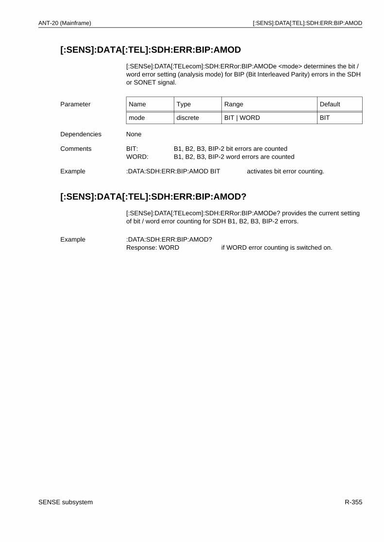
ANT-20 (Mainframe) [:SENS]:DATA[:TEL]:SDH:ERR:BIP:AMOD
[:SENS]:DATA[:TEL]:SDH:ERR:BIP:AMOD
[:SENSe]:DATA[:TELecom]:SDH:ERRor:BIP:AMODe <mode> determines the bit / word error setting (analysis mode) for BIP (Bit Interleaved Parity) errors in the SDH or SONET signal.
[:SENS]:DATA[:TEL]:SDH:ERR:BIP:AMOD?
[:SENSe]:DATA[:TELecom]:SDH:ERRor:BIP:AMODe? provides the current setting of bit / word error counting for SDH B1, B2, B3, BIP-2 errors.
Parameter Name Type Range Default
mode discrete BIT | WORD BIT
Dependencies None
Comments BIT: B1, B2, B3, BIP-2 bit errors are countedWORD: B1, B2, B3, BIP-2 word errors are counted
Example :DATA:SDH:ERR:BIP:AMOD BIT activates bit error counting.
Example :DATA:SDH:ERR:BIP:AMOD?Response: WORD if WORD error counting is switched on.
SENSE subsystem R-355
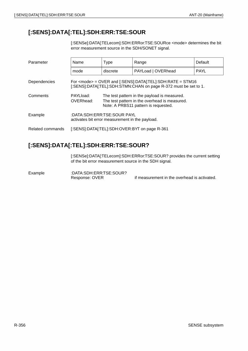
[:SENS]:DATA[:TEL]:SDH:ERR:TSE:SOUR ANT-20 (Mainframe)
[:SENS]:DATA[:TEL]:SDH:ERR:TSE:SOUR
[:SENSe]:DATA[:TELecom]:SDH:ERRor:TSE:SOURce <mode> determines the bit error measurement source in the SDH/SONET signal.
[:SENS]:DATA[:TEL]:SDH:ERR:TSE:SOUR?
[:SENSe]:DATA[:TELecom]:SDH:ERRor:TSE:SOUR? provides the current setting of the bit error measurement source in the SDH signal.
Parameter Name Type Range Default
mode discrete PAYLoad | OVERhead PAYL
Dependencies For <mode> = OVER and [:SENS]:DATA[:TEL]:SDH:RATE = STM16 [:SENS]:DATA[:TEL]:SDH:STMN:CHAN on page R-372 must be set to 1.
Comments PAYLload: The test pattern in the payload is measured.OVERhead: The test pattern in the overhead is measured.
Note: A PRBS11 pattern is requested.
Example :DATA:SDH:ERR:TSE:SOUR PAYLactivates bit error measurement in the payload.
Related commands [:SENS]:DATA[:TEL]:SDH:OVER:BYT on page R-361
Example :DATA:SDH:ERR:TSE:SOUR?Response: OVER if measurement in the overhead is activated.
R-356 SENSE subsystem
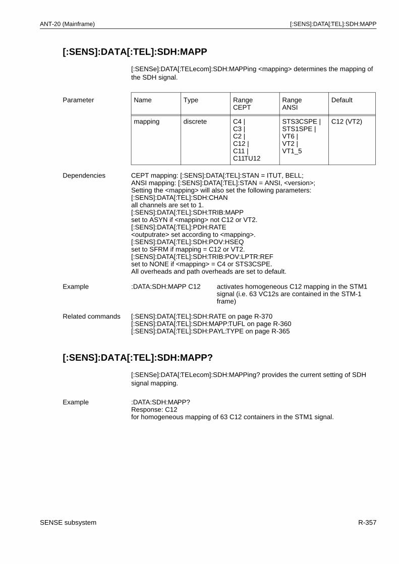
ANT-20 (Mainframe) [:SENS]:DATA[:TEL]:SDH:MAPP
[:SENS]:DATA[:TEL]:SDH:MAPP
[:SENSe]:DATA[:TELecom]:SDH:MAPPing <mapping> determines the mapping of the SDH signal.
[:SENS]:DATA[:TEL]:SDH:MAPP?
[:SENSe]:DATA[:TELecom]:SDH:MAPPing? provides the current setting of SDH signal mapping.
Parameter Name Type RangeCEPT
RangeANSI
Default
mapping discrete C4 |C3 |C2 |C12 |C11 |C11TU12
STS3CSPE |STS1SPE |VT6 |VT2 |VT1_5
C12 (VT2)
Dependencies CEPT mapping: [:SENS]:DATA[:TEL]:STAN = ITUT, BELL;ANSI mapping: [:SENS]:DATA[:TEL]:STAN = ANSI, <version>;Setting the <mapping> will also set the following parameters:[:SENS]:DATA[:TEL]:SDH:CHANall channels are set to 1.[:SENS]:DATA[:TEL]:SDH:TRIB:MAPPset to ASYN if <mapping> not C12 or VT2.[:SENS]:DATA[:TEL]:PDH:RATE<outputrate> set according to <mapping>.[:SENS]:DATA[:TEL]:SDH:POV:HSEQset to SFRM if mapping = C12 or VT2.[:SENS]:DATA[:TEL]:SDH:TRIB:POV:LPTR:REFset to NONE if <mapping> = C4 or STS3CSPE.All overheads and path overheads are set to default.
Example :DATA:SDH:MAPP C12 activates homogeneous C12 mapping in the STM1 signal (i.e. 63 VC12s are contained in the STM-1 frame)
Related commands [:SENS]:DATA[:TEL]:SDH:RATE on page R-370[:SENS]:DATA[:TEL]:SDH:MAPP:TUFL on page R-360[:SENS]:DATA[:TEL]:SDH:PAYL:TYPE on page R-365
Example :DATA:SDH:MAPP?Response: C12for homogeneous mapping of 63 C12 containers in the STM1 signal.
SENSE subsystem R-357
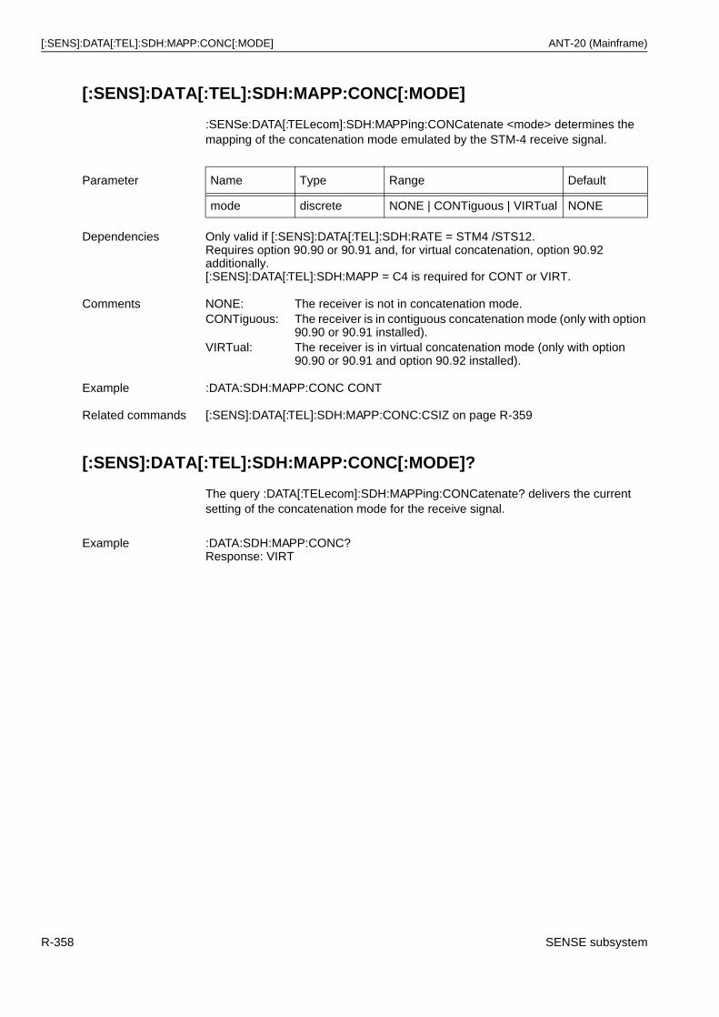
[:SENS]:DATA[:TEL]:SDH:MAPP:CONC[:MODE] ANT-20 (Mainframe)
[:SENS]:DATA[:TEL]:SDH:MAPP:CONC[:MODE]
:SENSe:DATA[:TELecom]:SDH:MAPPing:CONCatenate <mode> determines the mapping of the concatenation mode emulated by the STM-4 receive signal.
[:SENS]:DATA[:TEL]:SDH:MAPP:CONC[:MODE]?
The query :DATA[:TELecom]:SDH:MAPPing:CONCatenate? delivers the current setting of the concatenation mode for the receive signal.
Parameter Name Type Range Default
mode discrete NONE | CONTiguous | VIRTual NONE
Dependencies Only valid if [:SENS]:DATA[:TEL]:SDH:RATE = STM4 /STS12.Requires option 90.90 or 90.91 and, for virtual concatenation, option 90.92 additionally.[:SENS]:DATA[:TEL]:SDH:MAPP = C4 is required for CONT or VIRT.
Comments NONE: The receiver is not in concatenation mode.CONTiguous: The receiver is in contiguous concatenation mode (only with option
90.90 or 90.91 installed).VIRTual: The receiver is in virtual concatenation mode (only with option
90.90 or 90.91 and option 90.92 installed).
Example :DATA:SDH:MAPP:CONC CONT
Related commands [:SENS]:DATA[:TEL]:SDH:MAPP:CONC:CSIZ on page R-359
Example :DATA:SDH:MAPP:CONC?Response: VIRT
R-358 SENSE subsystem
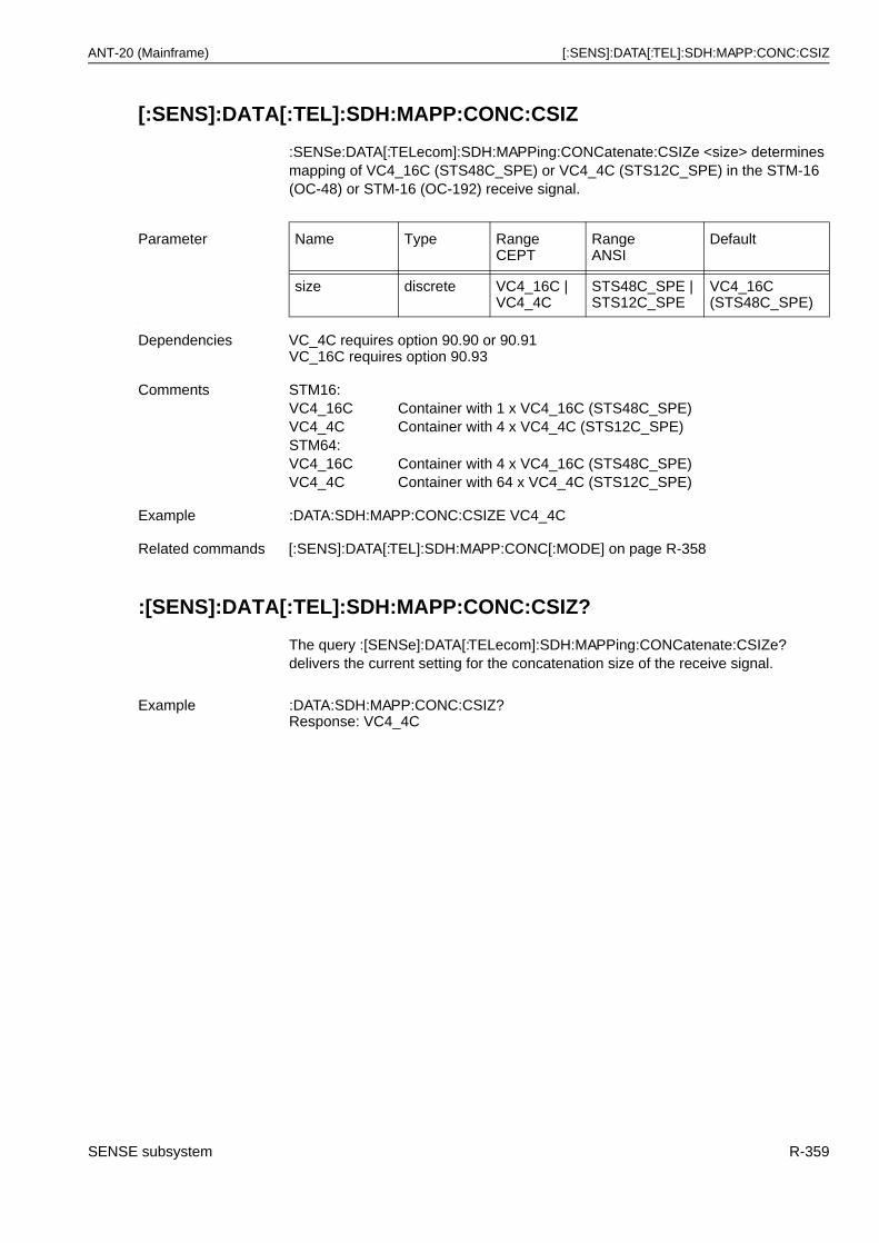
ANT-20 (Mainframe) [:SENS]:DATA[:TEL]:SDH:MAPP:CONC:CSIZ
[:SENS]:DATA[:TEL]:SDH:MAPP:CONC:CSIZ
:SENSe:DATA[:TELecom]:SDH:MAPPing:CONCatenate:CSIZe <size> determines mapping of VC4_16C (STS48C_SPE) or VC4_4C (STS12C_SPE) in the STM-16 (OC-48) or STM-16 (OC-192) receive signal.
.
:[SENS]:DATA[:TEL]:SDH:MAPP:CONC:CSIZ?
The query :[SENSe]:DATA[:TELecom]:SDH:MAPPing:CONCatenate:CSIZe? delivers the current setting for the concatenation size of the receive signal.
Parameter Name Type RangeCEPT
RangeANSI
Default
size discrete VC4_16C |VC4_4C
STS48C_SPE | STS12C_SPE
VC4_16C (STS48C_SPE)
Dependencies VC_4C requires option 90.90 or 90.91VC_16C requires option 90.93
Comments STM16:VC4_16C Container with 1 x VC4_16C (STS48C_SPE)VC4_4C Container with 4 x VC4_4C (STS12C_SPE)STM64:VC4_16C Container with 4 x VC4_16C (STS48C_SPE)VC4_4C Container with 64 x VC4_4C (STS12C_SPE)
Example :DATA:SDH:MAPP:CONC:CSIZE VC4_4C
Related commands [:SENS]:DATA[:TEL]:SDH:MAPP:CONC[:MODE] on page R-358
Example :DATA:SDH:MAPP:CONC:CSIZ?Response: VC4_4C
SENSE subsystem R-359
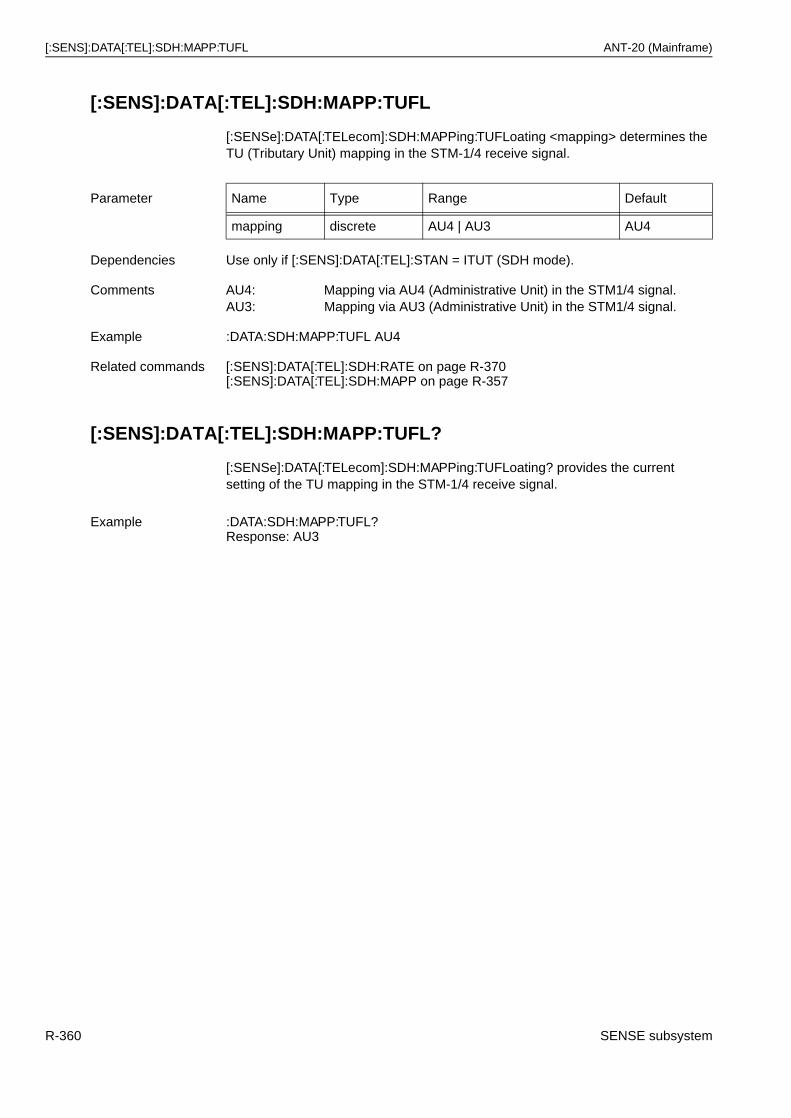
[:SENS]:DATA[:TEL]:SDH:MAPP:TUFL ANT-20 (Mainframe)
[:SENS]:DATA[:TEL]:SDH:MAPP:TUFL
[:SENSe]:DATA[:TELecom]:SDH:MAPPing:TUFLoating <mapping> determines the TU (Tributary Unit) mapping in the STM-1/4 receive signal.
[:SENS]:DATA[:TEL]:SDH:MAPP:TUFL?
[:SENSe]:DATA[:TELecom]:SDH:MAPPing:TUFLoating? provides the current setting of the TU mapping in the STM-1/4 receive signal.
Parameter Name Type Range Default
mapping discrete AU4 | AU3 AU4
Dependencies Use only if [:SENS]:DATA[:TEL]:STAN = ITUT (SDH mode).
Comments AU4: Mapping via AU4 (Administrative Unit) in the STM1/4 signal.AU3: Mapping via AU3 (Administrative Unit) in the STM1/4 signal.
Example :DATA:SDH:MAPP:TUFL AU4
Related commands [:SENS]:DATA[:TEL]:SDH:RATE on page R-370[:SENS]:DATA[:TEL]:SDH:MAPP on page R-357
Example :DATA:SDH:MAPP:TUFL?Response: AU3
R-360 SENSE subsystem
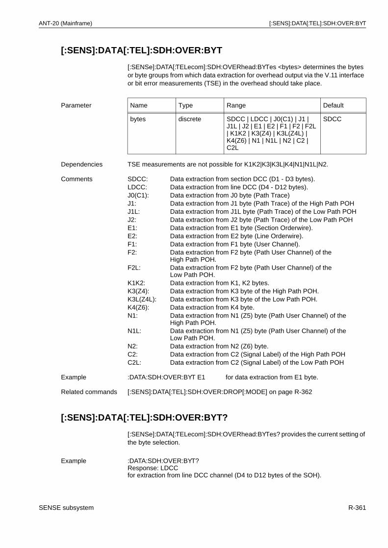
ANT-20 (Mainframe) [:SENS]:DATA[:TEL]:SDH:OVER:BYT
[:SENS]:DATA[:TEL]:SDH:OVER:BYT
[:SENSe]:DATA[:TELecom]:SDH:OVERhead:BYTes <bytes> determines the bytes or byte groups from which data extraction for overhead output via the V.11 interface or bit error measurements (TSE) in the overhead should take place.
[:SENS]:DATA[:TEL]:SDH:OVER:BYT?
[:SENSe]:DATA[:TELecom]:SDH:OVERhead:BYTes? provides the current setting of the byte selection.
Parameter Name Type Range Default
bytes discrete SDCC | LDCC | J0(C1) | J1 | J1L | J2 | E1 | E2 | F1 | F2 | F2L | K1K2 | K3(Z4) | K3L(Z4L) | K4(Z6) | N1 | N1L | N2 | C2 | C2L
SDCC
Dependencies TSE measurements are not possible for K1K2|K3|K3L|K4|N1|N1L|N2.
Comments SDCC: Data extraction from section DCC (D1 - D3 bytes).LDCC: Data extraction from line DCC (D4 - D12 bytes).J0(C1): Data extraction from J0 byte (Path Trace)J1: Data extraction from J1 byte (Path Trace) of the High Path POHJ1L: Data extraction from J1L byte (Path Trace) of the Low Path POHJ2: Data extraction from J2 byte (Path Trace) of the Low Path POHE1: Data extraction from E1 byte (Section Orderwire).E2: Data extraction from E2 byte (Line Orderwire).F1: Data extraction from F1 byte (User Channel).F2: Data extraction from F2 byte (Path User Channel) of the
High Path POH.F2L: Data extraction from F2 byte (Path User Channel) of the
Low Path POH.K1K2: Data extraction from K1, K2 bytes.K3(Z4): Data extraction from K3 byte of the High Path POH.K3L(Z4L): Data extraction from K3 byte of the Low Path POH.K4(Z6): Data extraction from K4 byte.N1: Data extraction from N1 (Z5) byte (Path User Channel) of the
High Path POH.N1L: Data extraction from N1 (Z5) byte (Path User Channel) of the
Low Path POH.N2: Data extraction from N2 (Z6) byte.C2: Data extraction from C2 (Signal Label) of the High Path POHC2L: Data extraction from C2 (Signal Label) of the Low Path POH
Example :DATA:SDH:OVER:BYT E1 for data extraction from E1 byte.
Related commands [:SENS]:DATA[:TEL]:SDH:OVER:DROP[:MODE] on page R-362
Example :DATA:SDH:OVER:BYT?Response: LDCCfor extraction from line DCC channel (D4 to D12 bytes of the SOH).
SENSE subsystem R-361
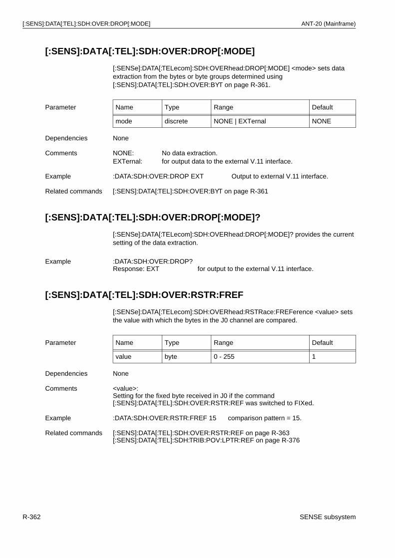
[:SENS]:DATA[:TEL]:SDH:OVER:DROP[:MODE] ANT-20 (Mainframe)
[:SENS]:DATA[:TEL]:SDH:OVER:DROP[:MODE]
[:SENSe]:DATA[:TELecom]:SDH:OVERhead:DROP[:MODE] <mode> sets data extraction from the bytes or byte groups determined using [:SENS]:DATA[:TEL]:SDH:OVER:BYT on page R-361.
[:SENS]:DATA[:TEL]:SDH:OVER:DROP[:MODE]?
[:SENSe]:DATA[:TELecom]:SDH:OVERhead:DROP[:MODE]? provides the current setting of the data extraction.
[:SENS]:DATA[:TEL]:SDH:OVER:RSTR:FREF
[:SENSe]:DATA[:TELecom]:SDH:OVERhead:RSTRace:FREFerence <value> sets the value with which the bytes in the J0 channel are compared.
Parameter Name Type Range Default
mode discrete NONE | EXTernal NONE
Dependencies None
Comments NONE: No data extraction.EXTernal: for output data to the external V.11 interface.
Example :DATA:SDH:OVER:DROP EXT Output to external V.11 interface.
Related commands [:SENS]:DATA[:TEL]:SDH:OVER:BYT on page R-361
Example :DATA:SDH:OVER:DROP?Response: EXT for output to the external V.11 interface.
Parameter Name Type Range Default
value byte 0 - 255 1
Dependencies None
Comments <value>:Setting for the fixed byte received in J0 if the command[:SENS]:DATA[:TEL]:SDH:OVER:RSTR:REF was switched to FIXed.
Example :DATA:SDH:OVER:RSTR:FREF 15 comparison pattern = 15.
Related commands [:SENS]:DATA[:TEL]:SDH:OVER:RSTR:REF on page R-363[:SENS]:DATA[:TEL]:SDH:TRIB:POV:LPTR:REF on page R-376
R-362 SENSE subsystem
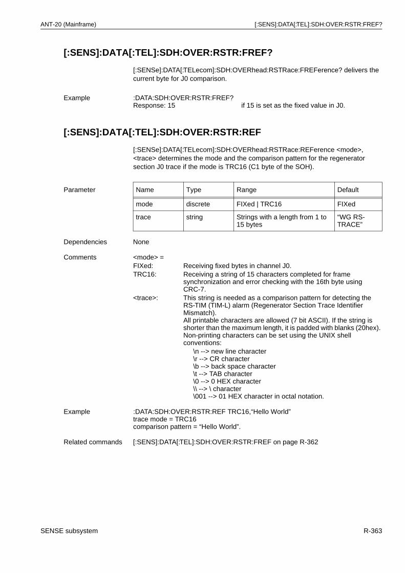
ANT-20 (Mainframe) [:SENS]:DATA[:TEL]:SDH:OVER:RSTR:FREF?
[:SENS]:DATA[:TEL]:SDH:OVER:RSTR:FREF?
[:SENSe]:DATA[:TELecom]:SDH:OVERhead:RSTRace:FREFerence? delivers the current byte for J0 comparison.
[:SENS]:DATA[:TEL]:SDH:OVER:RSTR:REF
[:SENSe]:DATA[:TELecom]:SDH:OVERhead:RSTRace:REFerence <mode>, <trace> determines the mode and the comparison pattern for the regenerator section J0 trace if the mode is TRC16 (C1 byte of the SOH).
Example :DATA:SDH:OVER:RSTR:FREF?Response: 15 if 15 is set as the fixed value in J0.
Parameter Name Type Range Default
mode discrete FIXed | TRC16 FIXed
trace string Strings with a length from 1 to 15 bytes
“WG RS-TRACE”
Dependencies None
Comments <mode> =FIXed: Receiving fixed bytes in channel J0.TRC16: Receiving a string of 15 characters completed for frame
synchronization and error checking with the 16th byte using CRC-7.
<trace>: This string is needed as a comparison pattern for detecting the RS-TIM (TIM-L) alarm (Regenerator Section Trace Identifier Mismatch).All printable characters are allowed (7 bit ASCII). If the string is shorter than the maximum length, it is padded with blanks (20hex). Non-printing characters can be set using the UNIX shell conventions:
\n --> new line character\r --> CR character\b --> back space character\t --> TAB character\0 --> 0 HEX character\\ --> \ character\001 --> 01 HEX character in octal notation.
Example :DATA:SDH:OVER:RSTR:REF TRC16,“Hello World”trace mode = TRC16comparison pattern = “Hello World”.
Related commands [:SENS]:DATA[:TEL]:SDH:OVER:RSTR:FREF on page R-362
SENSE subsystem R-363
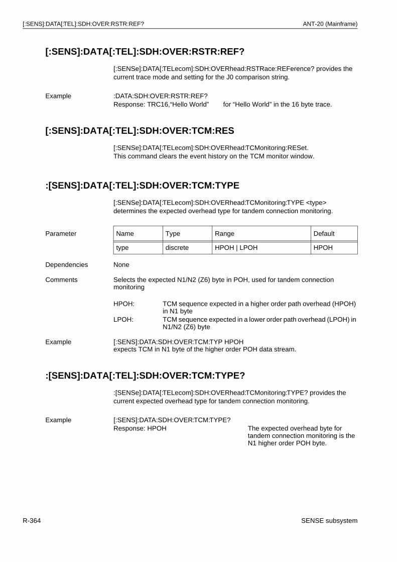
[:SENS]:DATA[:TEL]:SDH:OVER:RSTR:REF? ANT-20 (Mainframe)
[:SENS]:DATA[:TEL]:SDH:OVER:RSTR:REF?
[:SENSe]:DATA[:TELecom]:SDH:OVERhead:RSTRace:REFerence? provides the current trace mode and setting for the J0 comparison string.
[:SENS]:DATA[:TEL]:SDH:OVER:TCM:RES
[:SENSe]:DATA[:TELecom]:SDH:OVERhead:TCMonitoring:RESet.This command clears the event history on the TCM monitor window.
:[SENS]:DATA[:TEL]:SDH:OVER:TCM:TYPE
[:SENSe]:DATA[:TELecom]:SDH:OVERhead:TCMonitoring:TYPE <type> determines the expected overhead type for tandem connection monitoring.
:[SENS]:DATA[:TEL]:SDH:OVER:TCM:TYPE?
:[SENSe]:DATA[:TELecom]:SDH:OVERhead:TCMonitoring:TYPE? provides the current expected overhead type for tandem connection monitoring.
Example :DATA:SDH:OVER:RSTR:REF?Response: TRC16,“Hello World” for “Hello World” in the 16 byte trace.
Parameter Name Type Range Default
type discrete HPOH | LPOH HPOH
Dependencies None
Comments Selects the expected N1/N2 (Z6) byte in POH, used for tandem connection monitoring
HPOH: TCM sequence expected in a higher order path overhead (HPOH) in N1 byte
LPOH: TCM sequence expected in a lower order path overhead (LPOH) in N1/N2 (Z6) byte
Example [:SENS]:DATA:SDH:OVER:TCM:TYP HPOHexpects TCM in N1 byte of the higher order POH data stream.
Example [:SENS]:DATA:SDH:OVER:TCM:TYPE?Response: HPOH The expected overhead byte for
tandem connection monitoring is the N1 higher order POH byte.
R-364 SENSE subsystem
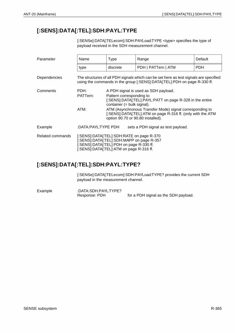
ANT-20 (Mainframe) [:SENS]:DATA[:TEL]:SDH:PAYL:TYPE
[:SENS]:DATA[:TEL]:SDH:PAYL:TYPE
[:SENSe]:DATA[:TELecom]:SDH:PAYLoad:TYPE <type> specifies the type of payload received in the SDH measurement channel.
[:SENS]:DATA[:TEL]:SDH:PAYL:TYPE?
[:SENSe]:DATA[:TELecom]:SDH:PAYLoad:TYPE? provides the current SDH payload in the measurement channel.
Parameter Name Type Range Default
type discrete PDH | PATTern | ATM PDH
Dependencies The structures of all PDH signals which can be set here as test signals are specified using the commands in the group [:SENS]:DATA[:TEL]:PDH on page R-330 ff.
Comments PDH: A PDH signal is used as SDH payload.PATTern: Pattern corresponding to
[:SENS]:DATA[:TEL]:PAYL:PATT on page R-328 in the entire container (= bulk signal).
ATM: ATM (Asynchronous Transfer Mode) signal corresponding to [:SENS]:DATA[:TEL]:ATM on page R-316 ff. (only with the ATM option 90.70 or 90.80 installed).
Example :DATA:PAYL:TYPE PDH sets a PDH signal as test payload.
Related commands [:SENS]:DATA[:TEL]:SDH:RATE on page R-370[:SENS]:DATA[:TEL]:SDH:MAPP on page R-357[:SENS]:DATA[:TEL]:PDH on page R-330 ff.[:SENS]:DATA[:TEL]:ATM on page R-316 ff.
Example :DATA:SDH:PAYL:TYPE?Response: PDH for a PDH signal as the SDH payload.
SENSE subsystem R-365
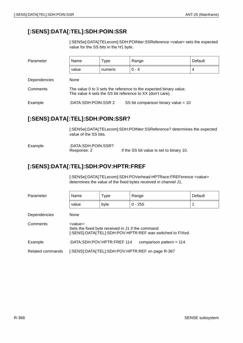
[:SENS]:DATA[:TEL]:SDH:POIN:SSR ANT-20 (Mainframe)
[:SENS]:DATA[:TEL]:SDH:POIN:SSR
[:SENSe]:DATA[:TELecom]:SDH:POINter:SSReference <value> sets the expected value for the SS bits in the H1 byte.
[:SENS]:DATA[:TEL]:SDH:POIN:SSR?
[:SENSe]:DATA[:TELecom]:SDH:POINter:SSReference? determines the expected value of the SS bits.
[:SENS]:DATA[:TEL]:SDH:POV:HPTR:FREF
[:SENSe]:DATA[:TELecom]:SDH:POVerhead:HPTRace:FREFerence <value> determines the value of the fixed bytes received in channel J1.
Parameter Name Type Range Default
value numeric 0 - 4 4
Dependencies None
Comments The value 0 to 3 sets the reference to the expected binary value.The value 4 sets the SS bit reference to XX (don’t care).
Example :DATA:SDH:POIN:SSR 2 SS bit comparison binary value = 10
Example :DATA:SDH:POIN:SSR?Response: 2 if the SS bit value is set to binary 10.
Parameter Name Type Range Default
value byte 0 - 255 1
Dependencies None
Comments <value>:Sets the fixed byte received in J1 if the command [:SENS]:DATA[:TEL]:SDH:POV:HPTR:REF was switched to FIXed.
Example :DATA:SDH:POV:HPTR:FREF 114 comparison pattern = 114.
Related commands [:SENS]:DATA[:TEL]:SDH:POV:HPTR:REF on page R-367
R-366 SENSE subsystem
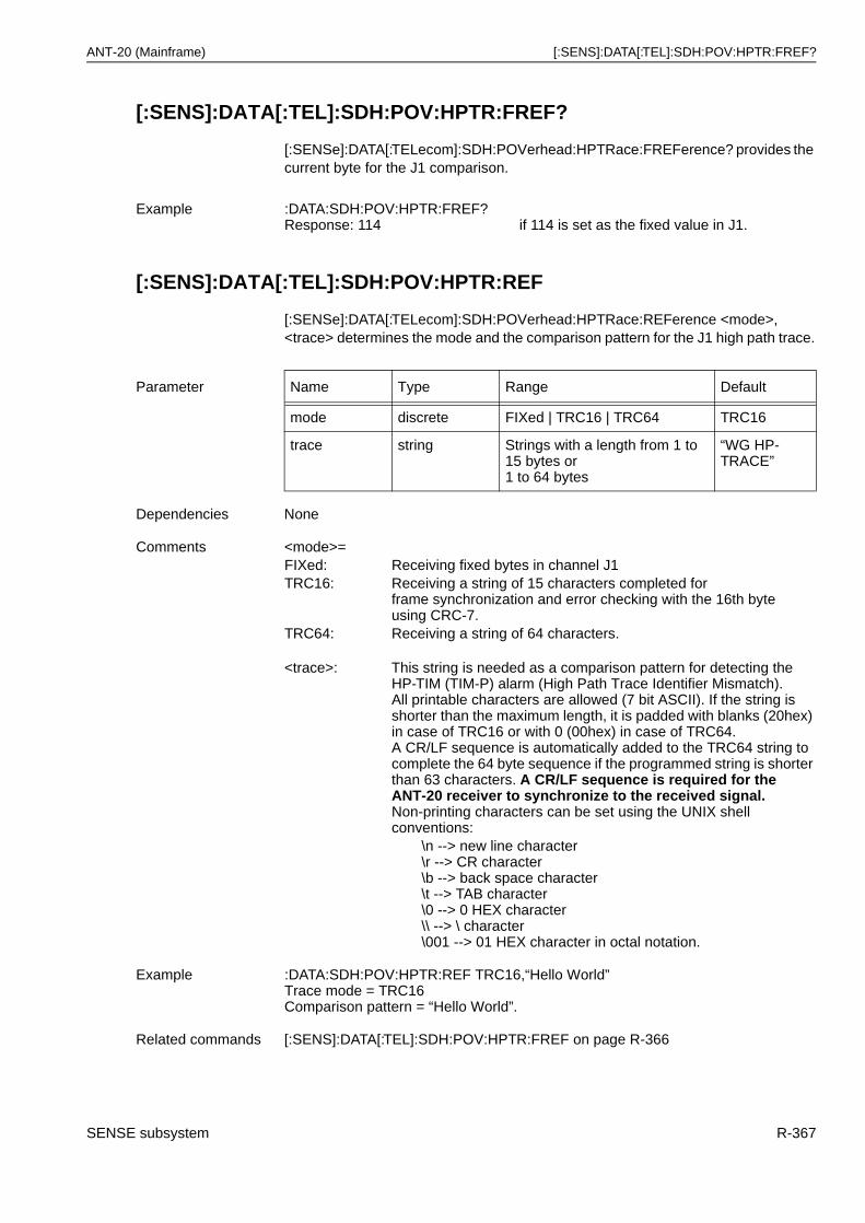
ANT-20 (Mainframe) [:SENS]:DATA[:TEL]:SDH:POV:HPTR:FREF?
[:SENS]:DATA[:TEL]:SDH:POV:HPTR:FREF?
[:SENSe]:DATA[:TELecom]:SDH:POVerhead:HPTRace:FREFerence? provides the current byte for the J1 comparison.
[:SENS]:DATA[:TEL]:SDH:POV:HPTR:REF
[:SENSe]:DATA[:TELecom]:SDH:POVerhead:HPTRace:REFerence <mode>, <trace> determines the mode and the comparison pattern for the J1 high path trace.
Example :DATA:SDH:POV:HPTR:FREF?Response: 114 if 114 is set as the fixed value in J1.
Parameter Name Type Range Default
mode discrete FIXed | TRC16 | TRC64 TRC16
trace string Strings with a length from 1 to 15 bytes or 1 to 64 bytes
“WG HP-TRACE”
Dependencies None
Comments <mode>=FIXed: Receiving fixed bytes in channel J1TRC16: Receiving a string of 15 characters completed for
frame synchronization and error checking with the 16th byteusing CRC-7.
TRC64: Receiving a string of 64 characters.
<trace>: This string is needed as a comparison pattern for detecting the HP-TIM (TIM-P) alarm (High Path Trace Identifier Mismatch).All printable characters are allowed (7 bit ASCII). If the string is shorter than the maximum length, it is padded with blanks (20hex) in case of TRC16 or with 0 (00hex) in case of TRC64.A CR/LF sequence is automatically added to the TRC64 string to complete the 64 byte sequence if the programmed string is shorter than 63 characters. A CR/LF sequence is required for the ANT-20 receiver to synchronize to the received signal.Non-printing characters can be set using the UNIX shell conventions:
\n --> new line character\r --> CR character\b --> back space character\t --> TAB character\0 --> 0 HEX character\\ --> \ character\001 --> 01 HEX character in octal notation.
Example :DATA:SDH:POV:HPTR:REF TRC16,“Hello World”Trace mode = TRC16Comparison pattern = “Hello World”.
Related commands [:SENS]:DATA[:TEL]:SDH:POV:HPTR:FREF on page R-366
SENSE subsystem R-367
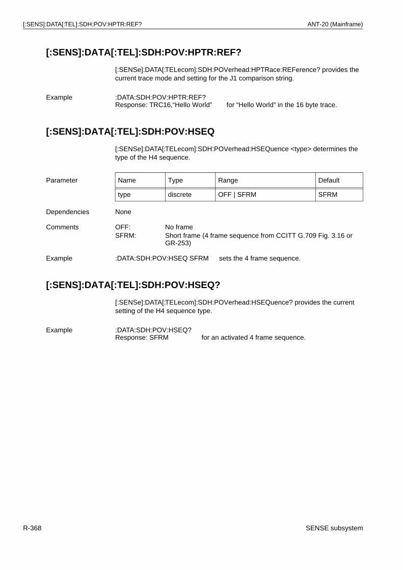
[:SENS]:DATA[:TEL]:SDH:POV:HPTR:REF? ANT-20 (Mainframe)
[:SENS]:DATA[:TEL]:SDH:POV:HPTR:REF?
[:SENSe]:DATA[:TELecom]:SDH:POVerhead:HPTRace:REFerence? provides the current trace mode and setting for the J1 comparison string.
[:SENS]:DATA[:TEL]:SDH:POV:HSEQ
[:SENSe]:DATA[:TELecom]:SDH:POVerhead:HSEQuence <type> determines the type of the H4 sequence.
[:SENS]:DATA[:TEL]:SDH:POV:HSEQ?
[:SENSe]:DATA[:TELecom]:SDH:POVerhead:HSEQuence? provides the current setting of the H4 sequence type.
Example :DATA:SDH:POV:HPTR:REF?Response: TRC16,“Hello World” for “Hello World” in the 16 byte trace.
Parameter Name Type Range Default
type discrete OFF | SFRM SFRM
Dependencies None
Comments OFF: No frameSFRM: Short frame (4 frame sequence from CCITT G.709 Fig. 3.16 or
GR-253)
Example :DATA:SDH:POV:HSEQ SFRM sets the 4 frame sequence.
Example :DATA:SDH:POV:HSEQ?Response: SFRM for an activated 4 frame sequence.
R-368 SENSE subsystem
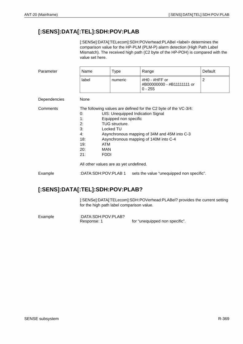
ANT-20 (Mainframe) [:SENS]:DATA[:TEL]:SDH:POV:PLAB
[:SENS]:DATA[:TEL]:SDH:POV:PLAB
[:SENSe]:DATA[:TELecom]:SDH:POVerhead:PLABel <label> determines the comparison value for the HP-PLM (PLM-P) alarm detection (High Path Label Mismatch). The received high path (C2 byte of the HP-POH) is compared with the value set here.
[:SENS]:DATA[:TEL]:SDH:POV:PLAB?
[:SENSe]:DATA[:TELecom]:SDH:POVerhead:PLABel? provides the current setting for the high path label comparison value.
Parameter Name Type Range Default
label numeric #H0 - #HFF or#B00000000 - #B11111111 or 0 - 255
2
Dependencies None
Comments The following values are defined for the C2 byte of the VC-3/4:0: UIS: Unequipped Indication Signal1: Equipped non specific2: TUG structure.3: Locked TU4: Asynchronous mapping of 34M and 45M into C-318: Asynchronous mapping of 140M into C-419: ATM20: MAN21: FDDI
All other values are as yet undefined.
Example :DATA:SDH:POV:PLAB 1 sets the value “unequipped non specific”.
Example :DATA:SDH:POV:PLAB?Response: 1 for “unequipped non specific”.
SENSE subsystem R-369
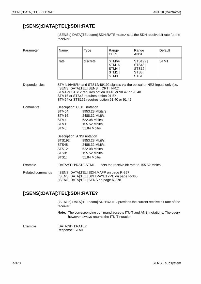
[:SENS]:DATA[:TEL]:SDH:RATE ANT-20 (Mainframe)
[:SENS]:DATA[:TEL]:SDH:RATE
[:SENSe]:DATA[:TELecom]:SDH:RATE <rate> sets the SDH receive bit rate for the receiver.
[:SENS]:DATA[:TEL]:SDH:RATE?
[:SENSe]:DATA[:TELecom]:SDH:RATE? provides the current receive bit rate of the receiver.
Note: The corresponding command accepts ITU-T and ANSI notations. The query however always returns the ITU-T notation.
Parameter Name Type RangeCEPT
RangeANSI
Default
rate discrete STM64 |STM16 |STM4 | STM1 | STM0
STS192 |STS48 |STS12 |STS3 |STS1
STM1
Dependencies STM4/16/48/64 and STS12/48/192 signals via the optical or NRZ inputs only (i.e. [:SENS]:DATA[:TEL]:SENS = OPT | NRZ).STM4 or STS12 requires option 90.46 or 90.47 or 90.48.STM16 or STS48 requires option 91.5X STM64 or STS192 requires option 91.40 or 91.42.
Comments Description: CEPT notationSTM64: 9953.28 Mbits/sSTM16: 2488.32 Mbit/sSTM4: 622.08 Mbit/sSTM1: 155.52 Mbit/sSTM0: 51.84 Mbit/s
Description: ANSI notationSTS192: 9953.28 Mbit/sSTS48: 2488.32 Mbit/sSTS12: 622.08 Mbit/sSTS3: 155.52 Mbit/sSTS1: 51.84 Mbit/s
Example :DATA:SDH:RATE STM1 sets the receive bit rate to 155.52 Mbit/s.
Related commands [:SENS]:DATA[:TEL]:SDH:MAPP on page R-357[:SENS]:DATA[:TEL]:SDH:PAYL:TYPE on page R-365[:SENS]:DATA[:TEL]:SENS on page R-378
Example :DATA:SDH:RATE?Response: STM1
R-370 SENSE subsystem
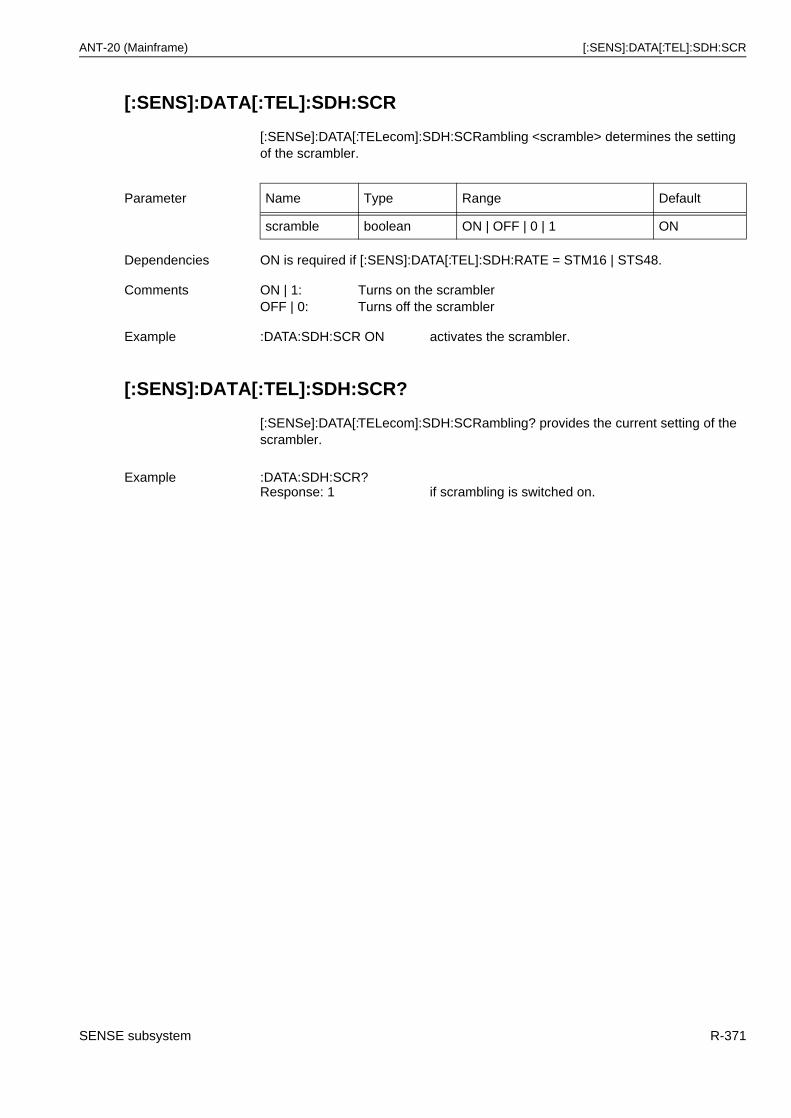
ANT-20 (Mainframe) [:SENS]:DATA[:TEL]:SDH:SCR
[:SENS]:DATA[:TEL]:SDH:SCR
[:SENSe]:DATA[:TELecom]:SDH:SCRambling <scramble> determines the setting of the scrambler.
[:SENS]:DATA[:TEL]:SDH:SCR?
[:SENSe]:DATA[:TELecom]:SDH:SCRambling? provides the current setting of the scrambler.
Parameter Name Type Range Default
scramble boolean ON | OFF | 0 | 1 ON
Dependencies ON is required if [:SENS]:DATA[:TEL]:SDH:RATE = STM16 | STS48.
Comments ON | 1: Turns on the scramblerOFF | 0: Turns off the scrambler
Example :DATA:SDH:SCR ON activates the scrambler.
Example :DATA:SDH:SCR?Response: 1 if scrambling is switched on.
SENSE subsystem R-371
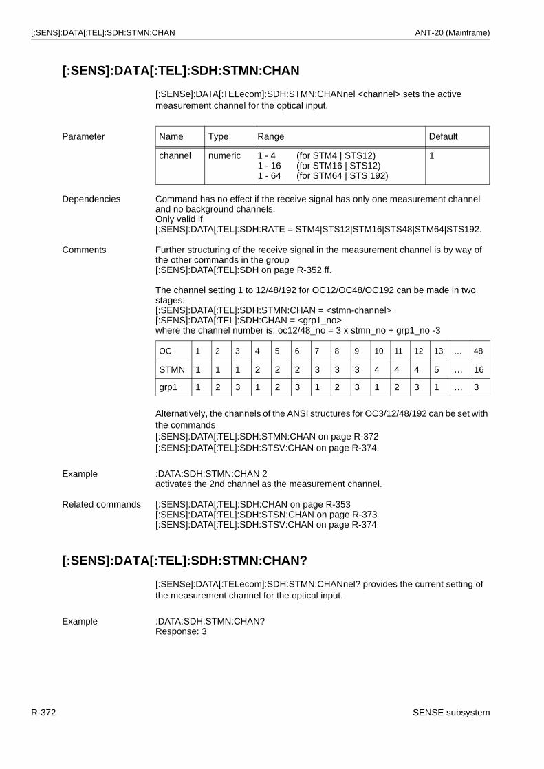
[:SENS]:DATA[:TEL]:SDH:STMN:CHAN ANT-20 (Mainframe)
[:SENS]:DATA[:TEL]:SDH:STMN:CHAN
[:SENSe]:DATA[:TELecom]:SDH:STMN:CHANnel <channel> sets the active measurement channel for the optical input.
Alternatively, the channels of the ANSI structures for OC3/12/48/192 can be set with the commands[:SENS]:DATA[:TEL]:SDH:STMN:CHAN on page R-372[:SENS]:DATA[:TEL]:SDH:STSV:CHAN on page R-374.
[:SENS]:DATA[:TEL]:SDH:STMN:CHAN?
[:SENSe]:DATA[:TELecom]:SDH:STMN:CHANnel? provides the current setting of the measurement channel for the optical input.
Parameter Name Type Range Default
channel numeric 1 - 41 - 161 - 64
(for STM4 | STS12) (for STM16 | STS12) (for STM64 | STS 192)
1
Dependencies Command has no effect if the receive signal has only one measurement channel and no background channels.Only valid if [:SENS]:DATA[:TEL]:SDH:RATE = STM4|STS12|STM16|STS48|STM64|STS192.
Comments Further structuring of the receive signal in the measurement channel is by way of the other commands in the group[:SENS]:DATA[:TEL]:SDH on page R-352 ff.
The channel setting 1 to 12/48/192 for OC12/OC48/OC192 can be made in two stages:[:SENS]:DATA[:TEL]:SDH:STMN:CHAN = <stmn-channel>[:SENS]:DATA[:TEL]:SDH:CHAN = <grp1_no>where the channel number is: oc12/48_no = 3 x stmn_no + grp1_no -3
OC 1 2 3 4 5 6 7 8 9 10 11 12 13 … 48
STMN 1 1 1 2 2 2 3 3 3 4 4 4 5 … 16
grp1 1 2 3 1 2 3 1 2 3 1 2 3 1 … 3
Example :DATA:SDH:STMN:CHAN 2activates the 2nd channel as the measurement channel.
Related commands [:SENS]:DATA[:TEL]:SDH:CHAN on page R-353[:SENS]:DATA[:TEL]:SDH:STSN:CHAN on page R-373[:SENS]:DATA[:TEL]:SDH:STSV:CHAN on page R-374
Example :DATA:SDH:STMN:CHAN?Response: 3
R-372 SENSE subsystem
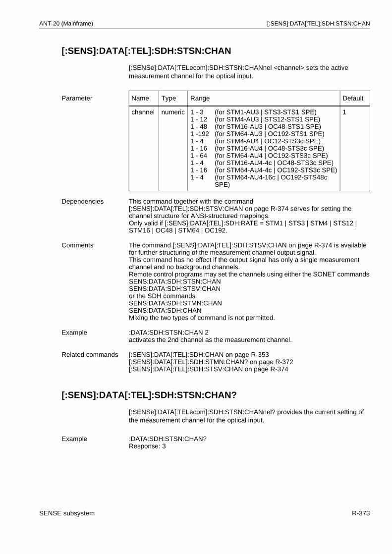
ANT-20 (Mainframe) [:SENS]:DATA[:TEL]:SDH:STSN:CHAN
[:SENS]:DATA[:TEL]:SDH:STSN:CHAN
[:SENSe]:DATA[:TELecom]:SDH:STSN:CHANnel <channel> sets the active measurement channel for the optical input.
[:SENS]:DATA[:TEL]:SDH:STSN:CHAN?
[:SENSe]:DATA[:TELecom]:SDH:STSN:CHANnel? provides the current setting of the measurement channel for the optical input.
Parameter Name Type Range Default
channel numeric 1 - 31 - 121 - 481 -1921 - 41 - 161 - 641 - 41 - 161 - 4
(for STM1-AU3 | STS3-STS1 SPE)(for STM4-AU3 | STS12-STS1 SPE)(for STM16-AU3 | OC48-STS1 SPE)(for STM64-AU3 | OC192-STS1 SPE)(for STM4-AU4 | OC12-STS3c SPE)(for STM16-AU4 | OC48-STS3c SPE)(for STM64-AU4 | OC192-STS3c SPE)(for STM16-AU4-4c | OC48-STS3c SPE)(for STM64-AU4-4c | OC192-STS3c SPE)(for STM64-AU4-16c | OC192-STS48c SPE)
1
Dependencies This command together with the command [:SENS]:DATA[:TEL]:SDH:STSV:CHAN on page R-374 serves for setting the channel structure for ANSI-structured mappings.Only valid if [:SENS]:DATA[:TEL]:SDH:RATE = STM1 | STS3 | STM4 | STS12 | STM16 | OC48 | STM64 | OC192.
Comments The command [:SENS]:DATA[:TEL]:SDH:STSV:CHAN on page R-374 is available for further structuring of the measurement channel output signal.This command has no effect if the output signal has only a single measurement channel and no background channels.Remote control programs may set the channels using either the SONET commandsSENS:DATA:SDH:STSN:CHANSENS:DATA:SDH:STSV:CHANor the SDH commandsSENS:DATA:SDH:STMN:CHANSENS:DATA:SDH:CHANMixing the two types of command is not permitted.
Example :DATA:SDH:STSN:CHAN 2activates the 2nd channel as the measurement channel.
Related commands [:SENS]:DATA[:TEL]:SDH:CHAN on page R-353[:SENS]:DATA[:TEL]:SDH:STMN:CHAN? on page R-372[:SENS]:DATA[:TEL]:SDH:STSV:CHAN on page R-374
Example :DATA:SDH:STSN:CHAN?Response: 3
SENSE subsystem R-373
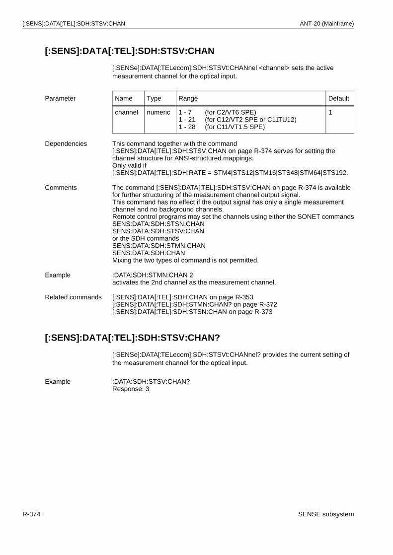
[:SENS]:DATA[:TEL]:SDH:STSV:CHAN ANT-20 (Mainframe)
[:SENS]:DATA[:TEL]:SDH:STSV:CHAN
[:SENSe]:DATA[:TELecom]:SDH:STSVt:CHANnel <channel> sets the active measurement channel for the optical input.
[:SENS]:DATA[:TEL]:SDH:STSV:CHAN?
[:SENSe]:DATA[:TELecom]:SDH:STSVt:CHANnel? provides the current setting of the measurement channel for the optical input.
Parameter Name Type Range Default
channel numeric 1 - 71 - 211 - 28
(for C2/VT6 SPE)(for C12/VT2 SPE or C11TU12)(for C11/VT1.5 SPE)
1
Dependencies This command together with the command [:SENS]:DATA[:TEL]:SDH:STSV:CHAN on page R-374 serves for setting the channel structure for ANSI-structured mappings.Only valid if [:SENS]:DATA[:TEL]:SDH:RATE = STM4|STS12|STM16|STS48|STM64|STS192.
Comments The command [:SENS]:DATA[:TEL]:SDH:STSV:CHAN on page R-374 is available for further structuring of the measurement channel output signal.This command has no effect if the output signal has only a single measurement channel and no background channels.Remote control programs may set the channels using either the SONET commandsSENS:DATA:SDH:STSN:CHANSENS:DATA:SDH:STSV:CHANor the SDH commandsSENS:DATA:SDH:STMN:CHANSENS:DATA:SDH:CHANMixing the two types of command is not permitted.
Example :DATA:SDH:STMN:CHAN 2activates the 2nd channel as the measurement channel.
Related commands [:SENS]:DATA[:TEL]:SDH:CHAN on page R-353[:SENS]:DATA[:TEL]:SDH:STMN:CHAN? on page R-372[:SENS]:DATA[:TEL]:SDH:STSN:CHAN on page R-373
Example :DATA:SDH:STSV:CHAN?Response: 3
R-374 SENSE subsystem
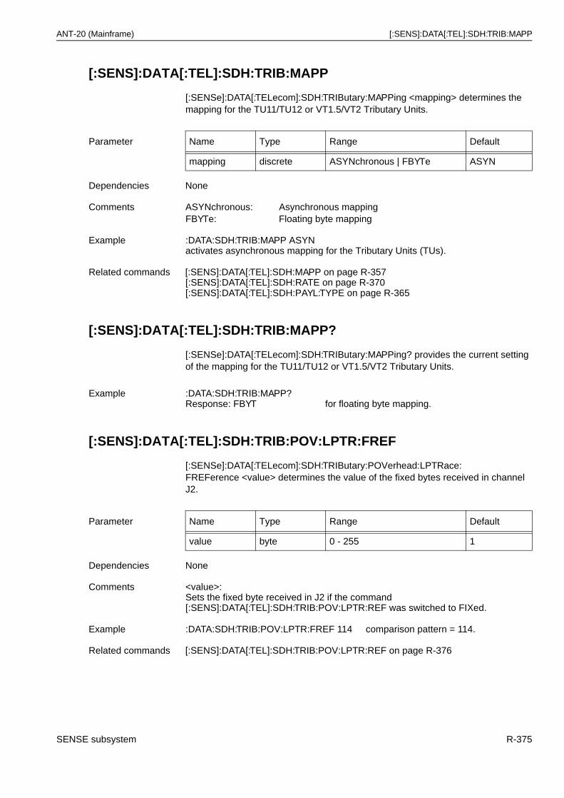
ANT-20 (Mainframe) [:SENS]:DATA[:TEL]:SDH:TRIB:MAPP
[:SENS]:DATA[:TEL]:SDH:TRIB:MAPP
[:SENSe]:DATA[:TELecom]:SDH:TRIButary:MAPPing <mapping> determines the mapping for the TU11/TU12 or VT1.5/VT2 Tributary Units.
[:SENS]:DATA[:TEL]:SDH:TRIB:MAPP?
[:SENSe]:DATA[:TELecom]:SDH:TRIButary:MAPPing? provides the current setting of the mapping for the TU11/TU12 or VT1.5/VT2 Tributary Units.
[:SENS]:DATA[:TEL]:SDH:TRIB:POV:LPTR:FREF
[:SENSe]:DATA[:TELecom]:SDH:TRIButary:POVerhead:LPTRace:FREFerence <value> determines the value of the fixed bytes received in channel J2.
Parameter Name Type Range Default
mapping discrete ASYNchronous | FBYTe ASYN
Dependencies None
Comments ASYNchronous: Asynchronous mappingFBYTe: Floating byte mapping
Example :DATA:SDH:TRIB:MAPP ASYNactivates asynchronous mapping for the Tributary Units (TUs).
Related commands [:SENS]:DATA[:TEL]:SDH:MAPP on page R-357[:SENS]:DATA[:TEL]:SDH:RATE on page R-370[:SENS]:DATA[:TEL]:SDH:PAYL:TYPE on page R-365
Example :DATA:SDH:TRIB:MAPP?Response: FBYT for floating byte mapping.
Parameter Name Type Range Default
value byte 0 - 255 1
Dependencies None
Comments <value>:Sets the fixed byte received in J2 if the command[:SENS]:DATA[:TEL]:SDH:TRIB:POV:LPTR:REF was switched to FIXed.
Example :DATA:SDH:TRIB:POV:LPTR:FREF 114 comparison pattern = 114.
Related commands [:SENS]:DATA[:TEL]:SDH:TRIB:POV:LPTR:REF on page R-376
SENSE subsystem R-375
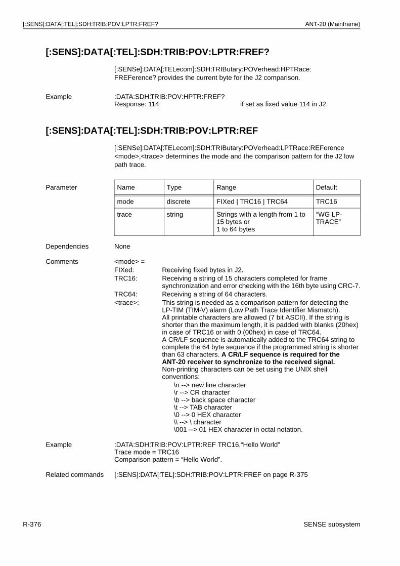
[:SENS]:DATA[:TEL]:SDH:TRIB:POV:LPTR:FREF? ANT-20 (Mainframe)
[:SENS]:DATA[:TEL]:SDH:TRIB:POV:LPTR:FREF?
[:SENSe]:DATA[:TELecom]:SDH:TRIButary:POVerhead:HPTRace:FREFerence? provides the current byte for the J2 comparison.
[:SENS]:DATA[:TEL]:SDH:TRIB:POV:LPTR:REF
[:SENSe]:DATA[:TELecom]:SDH:TRIButary:POVerhead:LPTRace:REFerence <mode>,<trace> determines the mode and the comparison pattern for the J2 low path trace.
Example :DATA:SDH:TRIB:POV:HPTR:FREF?Response: 114 if set as fixed value 114 in J2.
Parameter Name Type Range Default
mode discrete FIXed | TRC16 | TRC64 TRC16
trace string Strings with a length from 1 to 15 bytes or1 to 64 bytes
“WG LP-TRACE”
Dependencies None
Comments <mode> =FIXed: Receiving fixed bytes in J2.TRC16: Receiving a string of 15 characters completed for frame
synchronization and error checking with the 16th byte using CRC-7.TRC64: Receiving a string of 64 characters.<trace>: This string is needed as a comparison pattern for detecting the
LP-TIM (TIM-V) alarm (Low Path Trace Identifier Mismatch).All printable characters are allowed (7 bit ASCII). If the string isshorter than the maximum length, it is padded with blanks (20hex) in case of TRC16 or with 0 (00hex) in case of TRC64.A CR/LF sequence is automatically added to the TRC64 string to complete the 64 byte sequence if the programmed string is shorter than 63 characters. A CR/LF sequence is required for the ANT-20 receiver to synchronize to the received signal. Non-printing characters can be set using the UNIX shell conventions:
\n --> new line character\r --> CR character\b --> back space character\t --> TAB character\0 --> 0 HEX character\\ --> \ character\001 --> 01 HEX character in octal notation.
Example :DATA:SDH:TRIB:POV:LPTR:REF TRC16,“Hello World”Trace mode = TRC16Comparison pattern = “Hello World”.
Related commands [:SENS]:DATA[:TEL]:SDH:TRIB:POV:LPTR:FREF on page R-375
R-376 SENSE subsystem
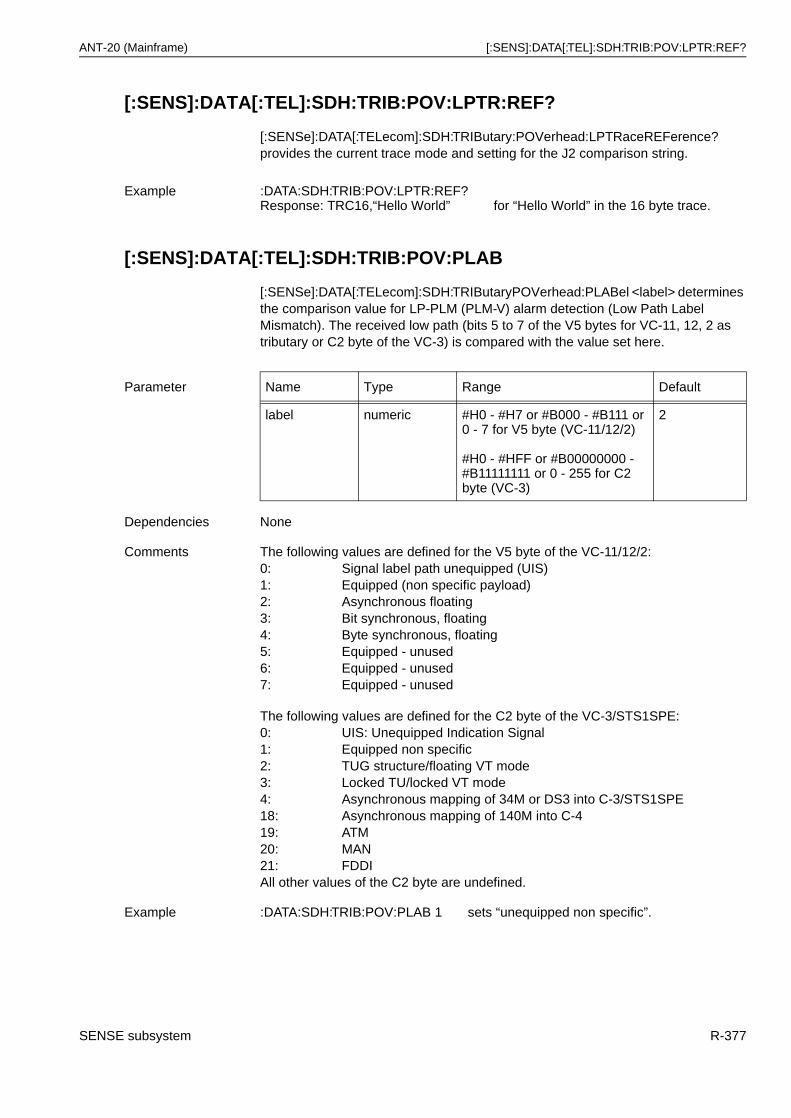
ANT-20 (Mainframe) [:SENS]:DATA[:TEL]:SDH:TRIB:POV:LPTR:REF?
[:SENS]:DATA[:TEL]:SDH:TRIB:POV:LPTR:REF?
[:SENSe]:DATA[:TELecom]:SDH:TRIButary:POVerhead:LPTRaceREFerence? provides the current trace mode and setting for the J2 comparison string.
[:SENS]:DATA[:TEL]:SDH:TRIB:POV:PLAB
[:SENSe]:DATA[:TELecom]:SDH:TRIButaryPOVerhead:PLABel <label> determines the comparison value for LP-PLM (PLM-V) alarm detection (Low Path Label Mismatch). The received low path (bits 5 to 7 of the V5 bytes for VC-11, 12, 2 as tributary or C2 byte of the VC-3) is compared with the value set here.
Example :DATA:SDH:TRIB:POV:LPTR:REF?Response: TRC16,“Hello World” for “Hello World” in the 16 byte trace.
Parameter Name Type Range Default
label numeric #H0 - #H7 or #B000 - #B111 or 0 - 7 for V5 byte (VC-11/12/2)
#H0 - #HFF or #B00000000 - #B11111111 or 0 - 255 for C2 byte (VC-3)
2
Dependencies None
Comments The following values are defined for the V5 byte of the VC-11/12/2:0: Signal label path unequipped (UIS)1: Equipped (non specific payload)2: Asynchronous floating3: Bit synchronous, floating4: Byte synchronous, floating5: Equipped - unused6: Equipped - unused7: Equipped - unused
The following values are defined for the C2 byte of the VC-3/STS1SPE:0: UIS: Unequipped Indication Signal1: Equipped non specific2: TUG structure/floating VT mode3: Locked TU/locked VT mode4: Asynchronous mapping of 34M or DS3 into C-3/STS1SPE18: Asynchronous mapping of 140M into C-419: ATM20: MAN21: FDDIAll other values of the C2 byte are undefined.
Example :DATA:SDH:TRIB:POV:PLAB 1 sets “unequipped non specific”.
SENSE subsystem R-377
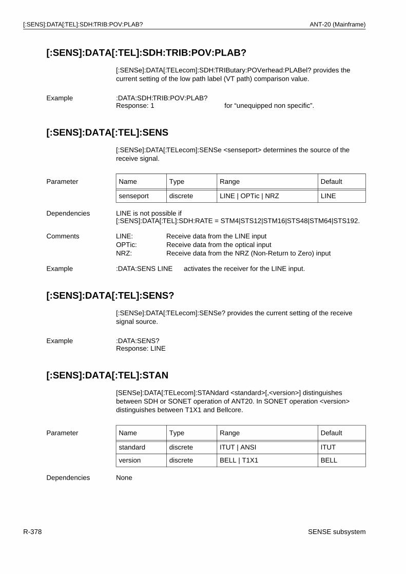
[:SENS]:DATA[:TEL]:SDH:TRIB:POV:PLAB? ANT-20 (Mainframe)
[:SENS]:DATA[:TEL]:SDH:TRIB:POV:PLAB?
[:SENSe]:DATA[:TELecom]:SDH:TRIButary:POVerhead:PLABel? provides the current setting of the low path label (VT path) comparison value.
[:SENS]:DATA[:TEL]:SENS
[:SENSe]:DATA[:TELecom]:SENSe <senseport> determines the source of the receive signal.
[:SENS]:DATA[:TEL]:SENS?
[:SENSe]:DATA[:TELecom]:SENSe? provides the current setting of the receive signal source.
[:SENS]:DATA[:TEL]:STAN
[SENSe]:DATA[:TELecom]:STANdard <standard>[,<version>] distinguishes between SDH or SONET operation of ANT20. In SONET operation <version> distinguishes between T1X1 and Bellcore.
Example :DATA:SDH:TRIB:POV:PLAB?Response: 1 for “unequipped non specific”.
Parameter Name Type Range Default
senseport discrete LINE | OPTic | NRZ LINE
Dependencies LINE is not possible if [:SENS]:DATA[:TEL]:SDH:RATE = STM4|STS12|STM16|STS48|STM64|STS192.
Comments LINE: Receive data from the LINE inputOPTic: Receive data from the optical inputNRZ: Receive data from the NRZ (Non-Return to Zero) input
Example :DATA:SENS LINE activates the receiver for the LINE input.
Example :DATA:SENS?Response: LINE
Parameter Name Type Range Default
standard discrete ITUT | ANSI ITUT
version discrete BELL | T1X1 BELL
Dependencies None
R-378 SENSE subsystem
ANT-20 (Mainframe) [:SENS]:DATA[:TEL]:STAN?
[:SENS]:DATA[:TEL]:STAN?
[:SENSe]:DATA[:TELecom]:STANdard? provides the current setting of the standard and the ANSI versions.
Comments <standard> =ITUT: SDH operation
The following settings are made automatically:[:SENS]:DATA[:TEL]:SDH:POV:HPTR:REF TRC16,”WG HP-TRACE”[:SENS]:DATA[:TEL]:SDH:TRIB:POV:LPTR:REF TRC16,”WG LP-TRACE”
ANSI: SONET operationThe following settings are made automatically:[:SENS]:DATA[:TEL]:SDH:POV:HPTR:REF TRC64,”WG STS-TRACE”[:SENS]:DATA[:TEL]:SDH:TRIB:POV:LPTR:REF TRC64,”WG VT-TRACE”
<version> = optional:BELL: Anomaly and defect processing (enhanced alarms)
according to GR253T1X1: Anomaly and defect processing (enhanced alarms)
according to T1X1
Example :DATA:STAN ANSI,T1X1 activates system for SONET operation (T1X1).
Related commands [:SENS]:DATA[:TEL]:SDH:POV:HPTR:REF on page R-367[:SENS]:DATA[:TEL]:SDH:TRIB:POV:LPTR:REF on page R-376
Example [:SENS]:DATA:STAN?Response: ANSI,T1X1
SENSE subsystem R-379
[:SENS]:FUNC:OFF ANT-20 (Mainframe)
[:SENS]:FUNC:OFF
[:SENSe]:FUNCtion:OFF <id>{, <id>} deletes one or more result elements from the list of results to be determined.
For the entire list of results, see Result IDs for :SENS:DATA and :SENS:FUNC commands on page R-382.
[:SENS]:FUNC:OFF:ALL
[:SENSe]:FUNCtion:OFF:ALL deletes all result elements from the list of results to be determined.
Parameter Name Type Range Default
id string e.g. “ECO:SDH:RSB” for counter value for SDH-B1 errors
none
Dependencies None
Example :FUNC:OFF “ECO:SDH:RSB”, “ECO:SDH:MSB”B1 & B2 error states are not to be determined.
Related commands [:SENS]:DATA:FIN? on page R-264[:SENS]:FUNC[:ON] on page R-381[:SENS]:FUNC:OFF:ALL on page R-380
Parameter None
Dependencies None
Comments There is no query for this command.
Example :FUNC:OFF:ALL deletes the entire list.
Related commands [:SENS]:DATA:FIN? on page R-264[:SENS]:FUNC[:ON] on page R-381[:SENS]:FUNC:OFF on page R-380
R-380 SENSE subsystem
ANT-20 (Mainframe) [:SENS]:FUNC[:ON]
[:SENS]:FUNC[:ON]
[:SENSe]:FUNCtion[:ON] <id>{, <id>} specifies the list of results to be determined.
For the entire list of results, see Result IDs for :SENS:DATA and :SENS:FUNC commands on page R-382.
[:SENS]:FUNC[:ON]?
[:SENSe]:FUNCtion[:ON]? provides the list of all interval end results that are currently selected.
Parameter Name Type Range Default
id string e.g. “ECO:SDH:RSB” for counter value for SDH-B1 errors
no result selected
Dependencies Only results previously activated with this command can be read by[:SENS]:DATA:FIN? or [:SENS]:DATA:ACT?(except results continuously taken).Only results previously activated with this command produce entries in the event memory (see also: [:SENS]:DATA:EVEN? on page R-266).
Comments The list of results to be determined can be very long (parameters separated by a blank). However, it does not have to be specified in a single command; several successive commands can be used.The results can then be read with [:SENS]:DATA:FIN? on page R-264 or [:SENS]:DATA:ACT? on page R-265.
Example :FUNC “ECO:SDH:RSB”, “ECO:SDH:MSB”B1 & B2 error states are to be determined.
Related commands [:SENS]:DATA:FIN? on page R-264[:SENS]:DATA:ACT? on page R-265[:SENS]:FUNC:OFF on page R-380[:SENS]:FUNC:OFF:ALL on page R-380
Example :FUNC?Response: “ECO:SDH:RSB”, “ECO:SDH:MSB”
SENSE subsystem R-381
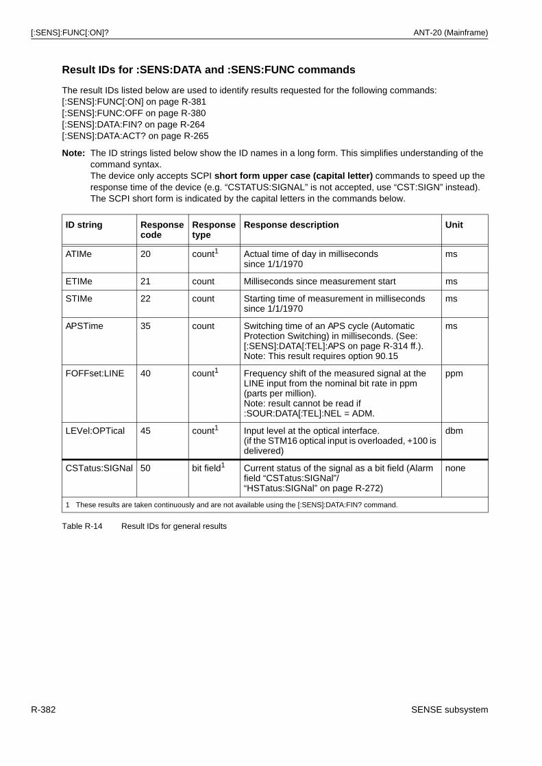
[:SENS]:FUNC[:ON]? ANT-20 (Mainframe)
Result IDs for :SENS:DATA and :SENS:FUNC commands
The result IDs listed below are used to identify results requested for the following commands:[:SENS]:FUNC[:ON] on page R-381[:SENS]:FUNC:OFF on page R-380[:SENS]:DATA:FIN? on page R-264[:SENS]:DATA:ACT? on page R-265
Note: The ID strings listed below show the ID names in a long form. This simplifies understanding of the command syntax.The device only accepts SCPI short form upper case (capital letter) commands to speed up the response time of the device (e.g. “CSTATUS:SIGNAL” is not accepted, use “CST:SIGN” instead).The SCPI short form is indicated by the capital letters in the commands below.
ID string Responsecode
Responsetype
Response description Unit
ATIMe 20 count1 Actual time of day in milliseconds since 1/1/1970
ms
ETIMe 21 count Milliseconds since measurement start ms
STIMe 22 count Starting time of measurement in milliseconds since 1/1/1970
ms
APSTime 35 count Switching time of an APS cycle (Automatic Protection Switching) in milliseconds. (See: [:SENS]:DATA[:TEL]:APS on page R-314 ff.).Note: This result requires option 90.15
ms
FOFFset:LINE 40 count1 Frequency shift of the measured signal at the LINE input from the nominal bit rate in ppm (parts per million).Note: result cannot be read if :SOUR:DATA[:TEL]:NEL = ADM.
ppm
LEVel:OPTical 45 count1 Input level at the optical interface.(if the STM16 optical input is overloaded, +100 is delivered)
dbm
CSTatus:SIGNal 50 bit field1 Current status of the signal as a bit field (Alarm field “CSTatus:SIGNal”/“HSTatus:SIGNal” on page R-272)
none
1 These results are taken continuously and are not available using the [:SENS]:DATA:FIN? command.
Table R-14 Result IDs for general results
R-382 SENSE subsystem
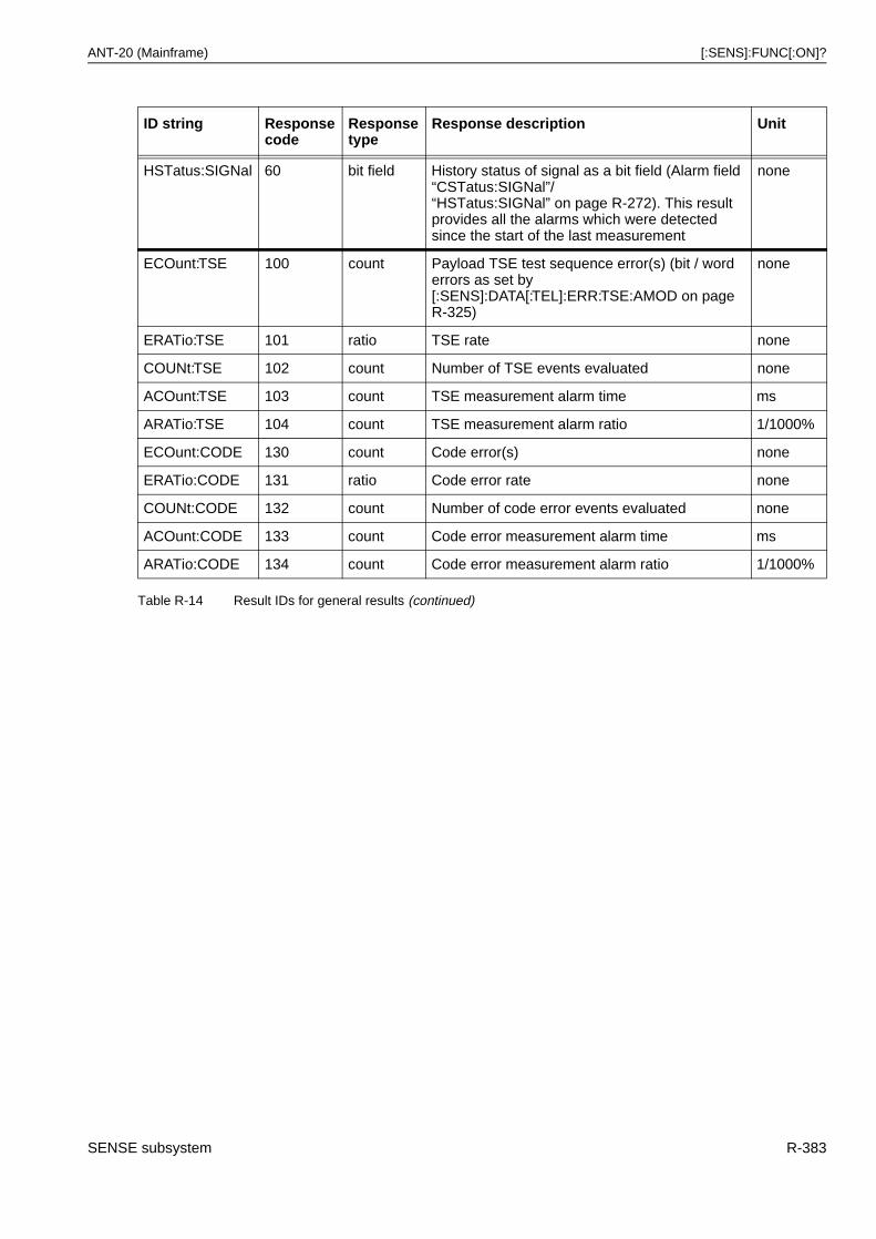
ANT-20 (Mainframe) [:SENS]:FUNC[:ON]?
HSTatus:SIGNal 60 bit field History status of signal as a bit field (Alarm field “CSTatus:SIGNal”/“HSTatus:SIGNal” on page R-272). This result provides all the alarms which were detected since the start of the last measurement
none
ECOunt:TSE 100 count Payload TSE test sequence error(s) (bit / word errors as set by [:SENS]:DATA[:TEL]:ERR:TSE:AMOD on pageR-325)
none
ERATio:TSE 101 ratio TSE rate none
COUNt:TSE 102 count Number of TSE events evaluated none
ACOunt:TSE 103 count TSE measurement alarm time ms
ARATio:TSE 104 count TSE measurement alarm ratio 1/1000%
ECOunt:CODE 130 count Code error(s) none
ERATio:CODE 131 ratio Code error rate none
COUNt:CODE 132 count Number of code error events evaluated none
ACOunt:CODE 133 count Code error measurement alarm time ms
ARATio:CODE 134 count Code error measurement alarm ratio 1/1000%
ID string Responsecode
Responsetype
Response description Unit
Table R-14 Result IDs for general results (continued)
SENSE subsystem R-383
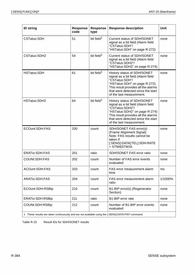
[:SENS]:FUNC[:ON]? ANT-20 (Mainframe)
ID string Responsecode
Responsetype
Response description Unit
CSTatus:SDH 51 bit field1 Current status of SDH/SONET signal as a bit field (Alarm field “CSTatus:SDH”/“HSTatus:SDH” on page R-272)
none
CSTatus:SDH2 54 bit field1 Current status of SDH/SONET signal as a bit field (Alarm field “CSTatus:SDH2”/“HSTatus:SDH2” on page R-274)
none
HSTatus:SDH 61 bit field1 History status of SDH/SONET signal as a bit field (Alarm field “CSTatus:SDH”/“HSTatus:SDH” on page R-272). This result provides all the alarms that were detected since the start of the last measurement.
none
HSTatus:SDH2 64 bit field1 History status of SDH/SONET signal as a bit field (Alarm field “CSTatus:SDH2”/“HSTatus:SDH2” on page R-274)This result provides all the alarms that were detected since the start of the last measurement.
none
ECOunt:SDH:FAS 200 count SDH/SONET FAS error(s) (Frame Alignment Signal)Note: FAS results cannot be taken if [:SENS]:DATA[:TEL]:SDH:RATE= STM4|STM16.
none
ERATio:SDH:FAS 201 ratio SDH/SONET FAS error ratio none
COUNt:SDH:FAS 202 count Number of FAS error events evaluated
none
ACOunt:SDH:FAS 203 count FAS error measurement alarm time
ms
ARATio:SDH:FAS 204 count FAS error measurement alarm ratio
1/1000%
ECOunt:SDH:RSBip 210 count B1-BIP error(s) (Regenerator Section)
none
ERATio:SDH:RSBip 211 ratio B1-BIP error rate none
COUNt:SDH:RSBip 212 count Number of B1-BIP error events evaluated
none
1 These results are taken continuously and are not available using the [:SENS]:DATA:FIN? command.
Table R-15 Result IDs for SDH/SONET results
R-384 SENSE subsystem
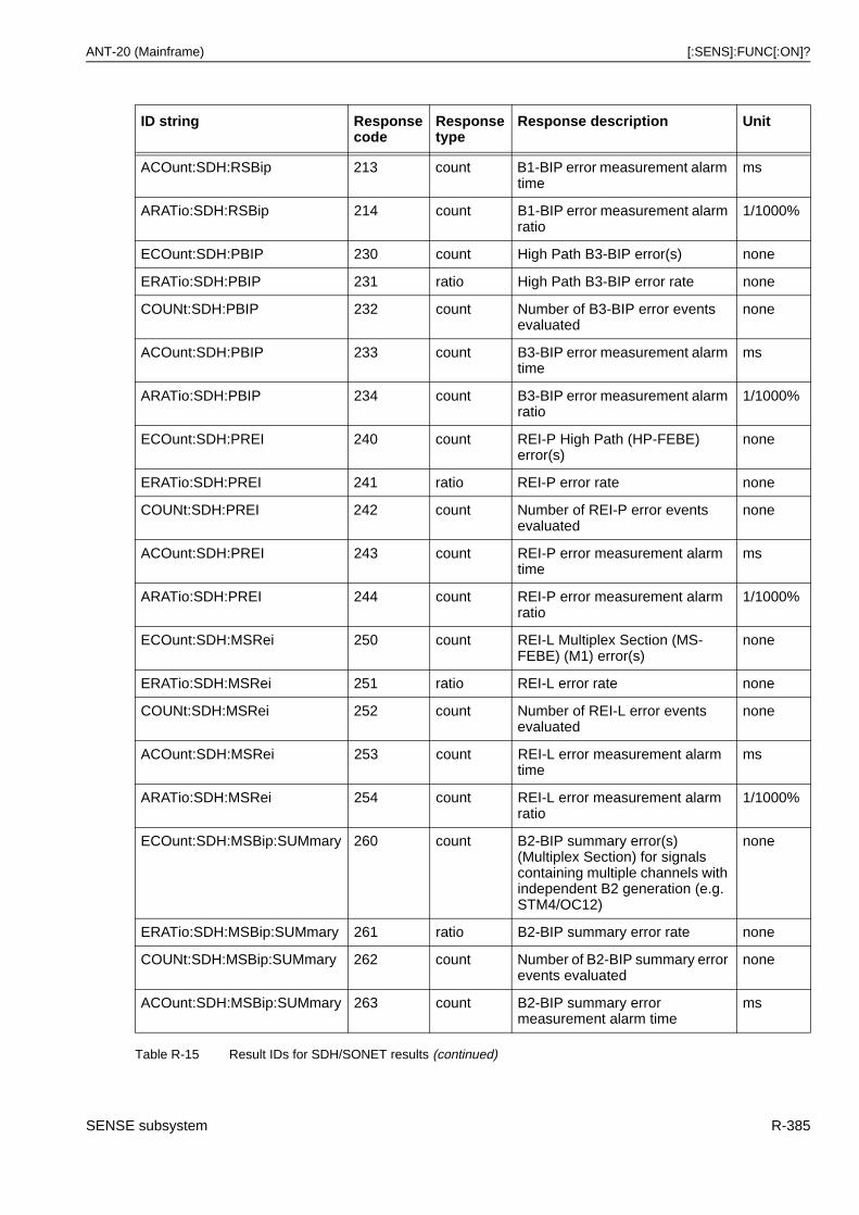
ANT-20 (Mainframe) [:SENS]:FUNC[:ON]?
ACOunt:SDH:RSBip 213 count B1-BIP error measurement alarm time
ms
ARATio:SDH:RSBip 214 count B1-BIP error measurement alarm ratio
1/1000%
ECOunt:SDH:PBIP 230 count High Path B3-BIP error(s) none
ERATio:SDH:PBIP 231 ratio High Path B3-BIP error rate none
COUNt:SDH:PBIP 232 count Number of B3-BIP error events evaluated
none
ACOunt:SDH:PBIP 233 count B3-BIP error measurement alarm time
ms
ARATio:SDH:PBIP 234 count B3-BIP error measurement alarm ratio
1/1000%
ECOunt:SDH:PREI 240 count REI-P High Path (HP-FEBE) error(s)
none
ERATio:SDH:PREI 241 ratio REI-P error rate none
COUNt:SDH:PREI 242 count Number of REI-P error events evaluated
none
ACOunt:SDH:PREI 243 count REI-P error measurement alarm time
ms
ARATio:SDH:PREI 244 count REI-P error measurement alarm ratio
1/1000%
ECOunt:SDH:MSRei 250 count REI-L Multiplex Section (MS-FEBE) (M1) error(s)
none
ERATio:SDH:MSRei 251 ratio REI-L error rate none
COUNt:SDH:MSRei 252 count Number of REI-L error events evaluated
none
ACOunt:SDH:MSRei 253 count REI-L error measurement alarm time
ms
ARATio:SDH:MSRei 254 count REI-L error measurement alarm ratio
1/1000%
ECOunt:SDH:MSBip:SUMmary 260 count B2-BIP summary error(s) (Multiplex Section) for signals containing multiple channels with independent B2 generation (e.g. STM4/OC12)
none
ERATio:SDH:MSBip:SUMmary 261 ratio B2-BIP summary error rate none
COUNt:SDH:MSBip:SUMmary 262 count Number of B2-BIP summary error events evaluated
none
ACOunt:SDH:MSBip:SUMmary 263 count B2-BIP summary error measurement alarm time
ms
ID string Responsecode
Responsetype
Response description Unit
Table R-15 Result IDs for SDH/SONET results (continued)
SENSE subsystem R-385
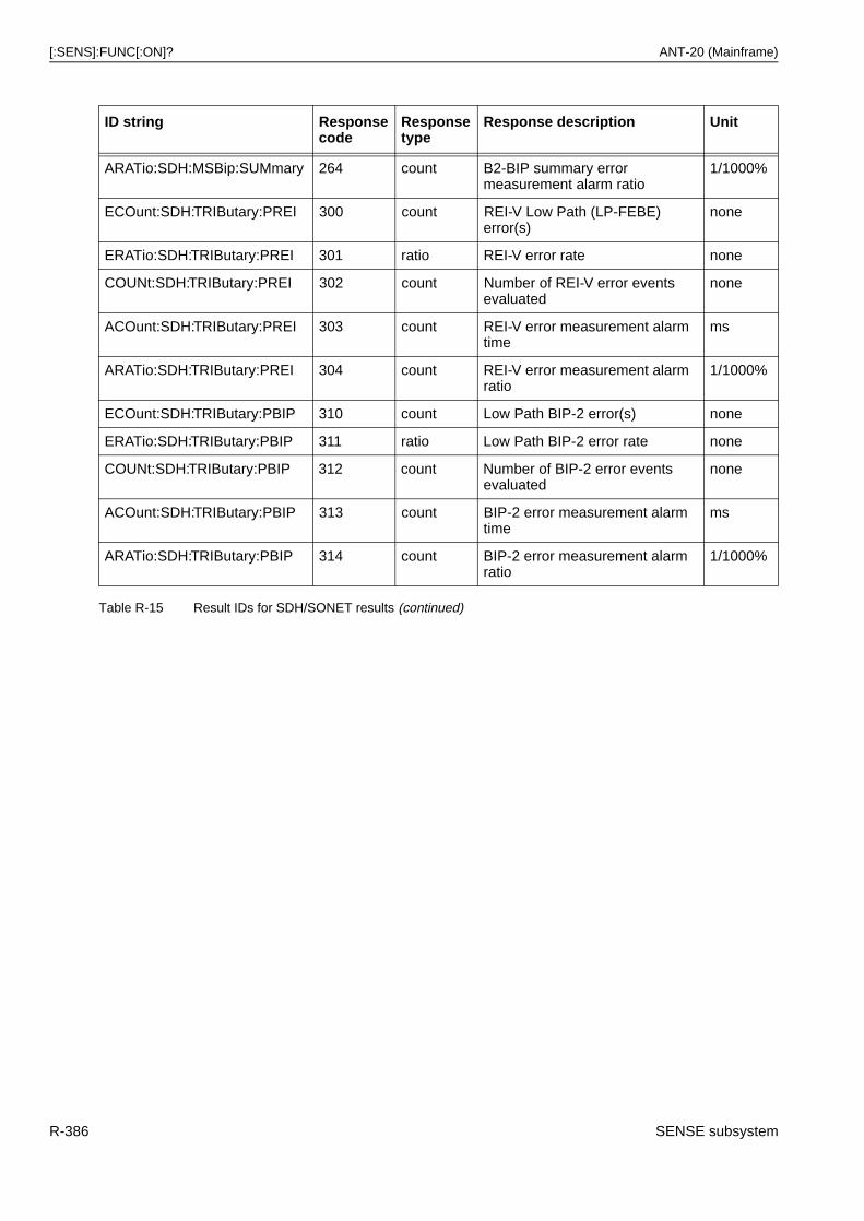
[:SENS]:FUNC[:ON]? ANT-20 (Mainframe)
ARATio:SDH:MSBip:SUMmary 264 count B2-BIP summary error measurement alarm ratio
1/1000%
ECOunt:SDH:TRIButary:PREI 300 count REI-V Low Path (LP-FEBE) error(s)
none
ERATio:SDH:TRIButary:PREI 301 ratio REI-V error rate none
COUNt:SDH:TRIButary:PREI 302 count Number of REI-V error events evaluated
none
ACOunt:SDH:TRIButary:PREI 303 count REI-V error measurement alarm time
ms
ARATio:SDH:TRIButary:PREI 304 count REI-V error measurement alarm ratio
1/1000%
ECOunt:SDH:TRIButary:PBIP 310 count Low Path BIP-2 error(s) none
ERATio:SDH:TRIButary:PBIP 311 ratio Low Path BIP-2 error rate none
COUNt:SDH:TRIButary:PBIP 312 count Number of BIP-2 error events evaluated
none
ACOunt:SDH:TRIButary:PBIP 313 count BIP-2 error measurement alarm time
ms
ARATio:SDH:TRIButary:PBIP 314 count BIP-2 error measurement alarm ratio
1/1000%
ID string Responsecode
Responsetype
Response description Unit
Table R-15 Result IDs for SDH/SONET results (continued)
R-386 SENSE subsystem
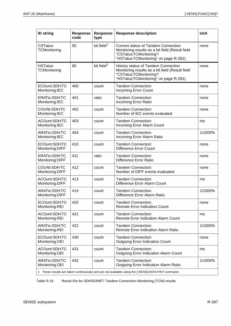
ANT-20 (Mainframe) [:SENS]:FUNC[:ON]?
ID string Responsecode
Responsetype
Response description Unit
CSTatus:TCMonitoring
55 bit field1 Current status of Tandem Connection Monitoring results as a bit field (Result field “CSTatus:TCMonitoring”/“HSTatus:TCMonitoring” on page R-281)
none
HSTatus:TCMonitoring
65 bit field1 History status of Tandem Connection Monitoring results as a bit field (Result field “CSTatus:TCMonitoring”/“HSTatus:TCMonitoring” on page R-281)
none
ECOunt:SDH:TCMonitoring:IEC
400 count Tandem Connection:Incoming Error Count
none
ERATio:SDH:TCMonitoring:IEC
401 ratio Tandem Connection:Incoming Error Ratio
none
COUNt:SDH:TCMonitoring:IEC
402 count Tandem Connection:Number of IEC events evaluated
none
ACOunt:SDH:TCMonitoring:IEC
403 count Tandem Connection:Incoming Error Alarm Count
ms
ARATio:SDH:TCMonitoring:IEC
404 count Tandem Connection:Incoming Error Alarm Ratio
1/1000%
ECOunt:SDH:TCMonitoring:DIFF
410 count Tandem Connection:Difference Error Count
none
ERATio:SDH:TCMonitoring:DIFF
411 ratio Tandem Connection:Difference Error Ratio
none
COUNt:SDH:TCMonitoring:DIFF
412 count Tandem Connection:Number of DIFF events evaluated
none
ACOunt:SDH:TCMonitoring:DIFF
413 count Tandem Connection:Difference Error Alarm Count
ms
ARATio:SDH:TCMonitoring:DIFF
414 count Tandem Connection:Difference Error Alarm Ratio
1/1000%
ECOunt:SDH:TCMonitoring:REI
420 count Tandem Connection:Remote Error Indication Count
none
ACOunt:SDH:TCMonitoring:REI
421 count Tandem Connection:Remote Error Indication Alarm Count
ms
ARATio:SDH:TCMonitoring:REI
422 count Tandem Connection:Remote Error Indication Alarm Ratio
1/1000%
ECOunt:SDH:TCMonitoring:OEI
430 count Tandem Connection:Outgoing Error Indication Count
none
ACOunt:SDH:TCMonitoring:OEI
431 count Tandem Connection:Outgoing Error Indication Alarm Count
ms
ARATio:SDH:TCMonitoring:OEI
432 count Tandem Connection:Outgoing Error Indication Alarm Ratio
1/1000%
1 These results are taken continuously and are not available using the [:SENS]:DATA:FIN? command.
Table R-16 Result IDs for SDH/SONET Tandem Connection Monitoring (TCM) results
SENSE subsystem R-387
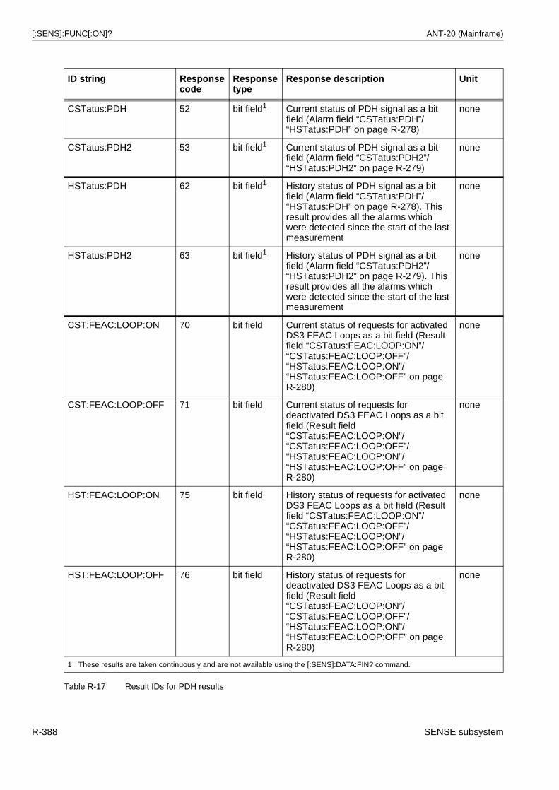
[:SENS]:FUNC[:ON]? ANT-20 (Mainframe)
ID string Responsecode
Responsetype
Response description Unit
CSTatus:PDH 52 bit field1 Current status of PDH signal as a bit field (Alarm field “CSTatus:PDH”/“HSTatus:PDH” on page R-278)
none
CSTatus:PDH2 53 bit field1 Current status of PDH signal as a bit field (Alarm field “CSTatus:PDH2”/“HSTatus:PDH2” on page R-279)
none
HSTatus:PDH 62 bit field1 History status of PDH signal as a bit field (Alarm field “CSTatus:PDH”/“HSTatus:PDH” on page R-278). This result provides all the alarms which were detected since the start of the last measurement
none
HSTatus:PDH2 63 bit field1 History status of PDH signal as a bit field (Alarm field “CSTatus:PDH2”/“HSTatus:PDH2” on page R-279). This result provides all the alarms which were detected since the start of the last measurement
none
CST:FEAC:LOOP:ON 70 bit field Current status of requests for activated DS3 FEAC Loops as a bit field (Result field “CSTatus:FEAC:LOOP:ON”/“CSTatus:FEAC:LOOP:OFF”/ “HSTatus:FEAC:LOOP:ON”/“HSTatus:FEAC:LOOP:OFF” on pageR-280)
none
CST:FEAC:LOOP:OFF 71 bit field Current status of requests for deactivated DS3 FEAC Loops as a bit field (Result field “CSTatus:FEAC:LOOP:ON”/“CSTatus:FEAC:LOOP:OFF”/ “HSTatus:FEAC:LOOP:ON”/“HSTatus:FEAC:LOOP:OFF” on pageR-280)
none
HST:FEAC:LOOP:ON 75 bit field History status of requests for activated DS3 FEAC Loops as a bit field (Result field “CSTatus:FEAC:LOOP:ON”/“CSTatus:FEAC:LOOP:OFF”/ “HSTatus:FEAC:LOOP:ON”/“HSTatus:FEAC:LOOP:OFF” on pageR-280)
none
HST:FEAC:LOOP:OFF 76 bit field History status of requests for deactivated DS3 FEAC Loops as a bit field (Result field “CSTatus:FEAC:LOOP:ON”/“CSTatus:FEAC:LOOP:OFF”/ “HSTatus:FEAC:LOOP:ON”/“HSTatus:FEAC:LOOP:OFF” on pageR-280)
none
1 These results are taken continuously and are not available using the [:SENS]:DATA:FIN? command.
Table R-17 Result IDs for PDH results
R-388 SENSE subsystem
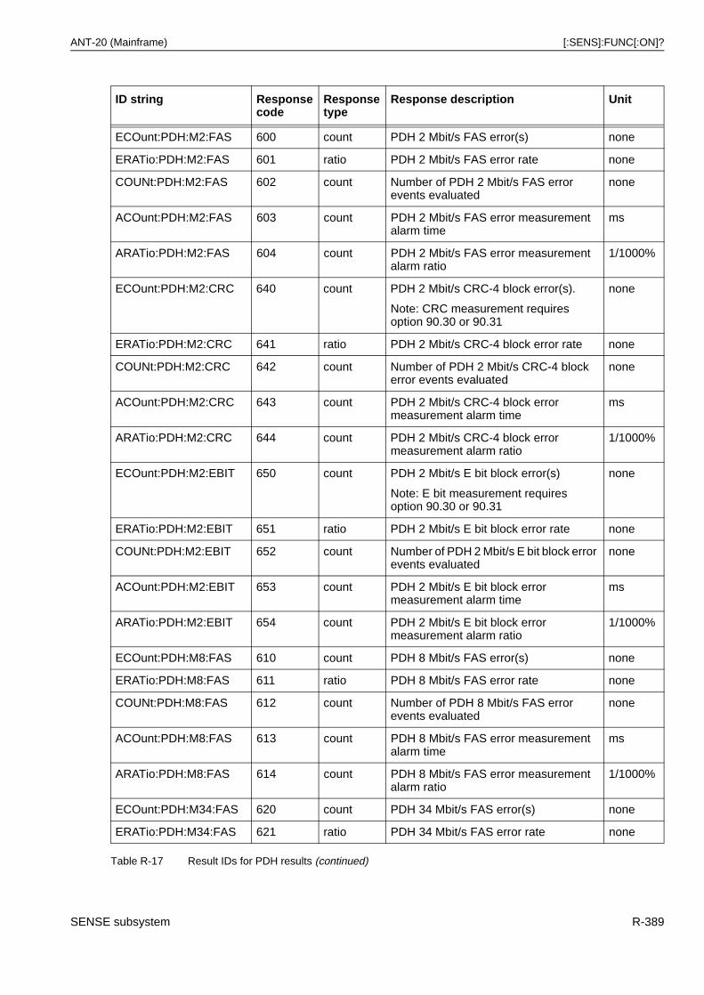
ANT-20 (Mainframe) [:SENS]:FUNC[:ON]?
ECOunt:PDH:M2:FAS 600 count PDH 2 Mbit/s FAS error(s) none
ERATio:PDH:M2:FAS 601 ratio PDH 2 Mbit/s FAS error rate none
COUNt:PDH:M2:FAS 602 count Number of PDH 2 Mbit/s FAS error events evaluated
none
ACOunt:PDH:M2:FAS 603 count PDH 2 Mbit/s FAS error measurement alarm time
ms
ARATio:PDH:M2:FAS 604 count PDH 2 Mbit/s FAS error measurement alarm ratio
1/1000%
ECOunt:PDH:M2:CRC 640 count PDH 2 Mbit/s CRC-4 block error(s).
Note: CRC measurement requires option 90.30 or 90.31
none
ERATio:PDH:M2:CRC 641 ratio PDH 2 Mbit/s CRC-4 block error rate none
COUNt:PDH:M2:CRC 642 count Number of PDH 2 Mbit/s CRC-4 block error events evaluated
none
ACOunt:PDH:M2:CRC 643 count PDH 2 Mbit/s CRC-4 block error measurement alarm time
ms
ARATio:PDH:M2:CRC 644 count PDH 2 Mbit/s CRC-4 block error measurement alarm ratio
1/1000%
ECOunt:PDH:M2:EBIT 650 count PDH 2 Mbit/s E bit block error(s)
Note: E bit measurement requires option 90.30 or 90.31
none
ERATio:PDH:M2:EBIT 651 ratio PDH 2 Mbit/s E bit block error rate none
COUNt:PDH:M2:EBIT 652 count Number of PDH 2 Mbit/s E bit block error events evaluated
none
ACOunt:PDH:M2:EBIT 653 count PDH 2 Mbit/s E bit block error measurement alarm time
ms
ARATio:PDH:M2:EBIT 654 count PDH 2 Mbit/s E bit block error measurement alarm ratio
1/1000%
ECOunt:PDH:M8:FAS 610 count PDH 8 Mbit/s FAS error(s) none
ERATio:PDH:M8:FAS 611 ratio PDH 8 Mbit/s FAS error rate none
COUNt:PDH:M8:FAS 612 count Number of PDH 8 Mbit/s FAS error events evaluated
none
ACOunt:PDH:M8:FAS 613 count PDH 8 Mbit/s FAS error measurement alarm time
ms
ARATio:PDH:M8:FAS 614 count PDH 8 Mbit/s FAS error measurement alarm ratio
1/1000%
ECOunt:PDH:M34:FAS 620 count PDH 34 Mbit/s FAS error(s) none
ERATio:PDH:M34:FAS 621 ratio PDH 34 Mbit/s FAS error rate none
ID string Responsecode
Responsetype
Response description Unit
Table R-17 Result IDs for PDH results (continued)
SENSE subsystem R-389
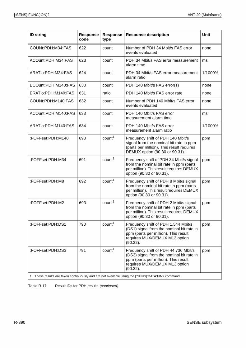
[:SENS]:FUNC[:ON]? ANT-20 (Mainframe)
COUNt:PDH:M34:FAS 622 count Number of PDH 34 Mbit/s FAS error events evaluated
none
ACOunt:PDH:M34:FAS 623 count PDH 34 Mbit/s FAS error measurement alarm time
ms
ARATio:PDH:M34:FAS 624 count PDH 34 Mbit/s FAS error measurement alarm ratio
1/1000%
ECOunt:PDH:M140:FAS 630 count PDH 140 Mbit/s FAS error(s) none
ERATio:PDH:M140:FAS 631 ratio PDH 140 Mbit/s FAS error rate none
COUNt:PDH:M140:FAS 632 count Number of PDH 140 Mbit/s FAS error events evaluated
none
ACOunt:PDH:M140:FAS 633 count PDH 140 Mbit/s FAS error measurement alarm time
ms
ARATio:PDH:M140:FAS 634 count PDH 140 Mbit/s FAS error measurement alarm ratio
1/1000%
:FOFFset:PDH:M140 690 count1 Frequency shift of PDH 140 Mbit/s signal from the nominal bit rate in ppm (parts per million). This result requires DEMUX option (90.30 or 90.31).
ppm
:FOFFset:PDH:M34 691 count1 Frequency shift of PDH 34 Mbit/s signal from the nominal bit rate in ppm (parts per million). This result requires DEMUX option (90.30 or 90.31).
ppm
:FOFFset:PDH:M8 692 count1 Frequency shift of PDH 8 Mbit/s signal from the nominal bit rate in ppm (parts per million). This result requires DEMUX option (90.30 or 90.31).
ppm
:FOFFset:PDH:M2 693 count1 Frequency shift of PDH 2 Mbit/s signal from the nominal bit rate in ppm (parts per million). This result requires DEMUX option (90.30 or 90.31).
ppm
:FOFFset:PDH:DS1 790 count1 Frequency shift of PDH 1.544 Mbit/s (DS1) signal from the nominal bit rate in ppm (parts per million). This result requires MUX/DEMUX M13 option (90.32).
ppm
:FOFFset:PDH:DS3 791 count1 Frequency shift of PDH 44.736 Mbit/s (DS3) signal from the nominal bit rate in ppm (parts per million). This result requires MUX/DEMUX M13 option (90.32).
ppm
1 These results are taken continuously and are not available using the [:SENS]:DATA:FIN? command.
ID string Responsecode
Responsetype
Response description Unit
Table R-17 Result IDs for PDH results (continued)
R-390 SENSE subsystem
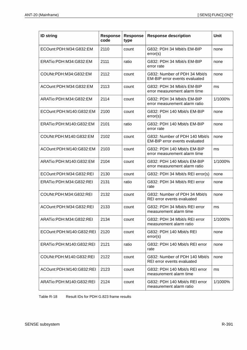
ANT-20 (Mainframe) [:SENS]:FUNC[:ON]?
ID string Responsecode
Responsetype
Response description Unit
ECOunt:PDH:M34:G832:EM 2110 count G832: PDH 34 Mbit/s EM-BIP error(s)
none
ERATio:PDH:M34:G832:EM 2111 ratio G832: PDH 34 Mbit/s EM-BIP error rate
none
COUNt:PDH:M34:G832:EM 2112 count G832: Number of PDH 34 Mbit/s EM-BIP error events evaluated
none
ACOunt:PDH:M34:G832:EM 2113 count G832: PDH 34 Mbit/s EM-BIP error measurement alarm time
ms
ARATio:PDH:M34:G832:EM 2114 count G832: PDH 34 Mbit/s EM-BIP error measurement alarm ratio
1/1000%
ECOunt:PDH:M140:G832:EM 2100 count G832: PDH 140 Mbit/s EM-BIP error(s)
none
ERATio:PDH:M140:G832:EM 2101 ratio G832: PDH 140 Mbit/s EM-BIP error rate
none
COUNt:PDH:M140:G832:EM 2102 count G832: Number of PDH 140 Mbit/s EM-BIP error events evaluated
none
ACOunt:PDH:M140:G832:EM 2103 count G832: PDH 140 Mbit/s EM-BIP error measurement alarm time
ms
ARATio:PDH:M140:G832:EM 2104 count G832: PDH 140 Mbit/s EM-BIP error measurement alarm ratio
1/1000%
ECOunt:PDH:M34:G832:REI 2130 count G832: PDH 34 Mbit/s REI error(s) none
ERATio:PDH:M34:G832:REI 2131 ratio G832: PDH 34 Mbit/s REI error rate
none
COUNt:PDH:M34:G832:REI 2132 count G832: Number of PDH 34 Mbit/s REI error events evaluated
none
ACOunt:PDH:M34:G832:REI 2133 count G832: PDH 34 Mbit/s REI error measurement alarm time
ms
ARATio:PDH:M34:G832:REI 2134 count G832: PDH 34 Mbit/s REI error measurement alarm ratio
1/1000%
ECOunt:PDH:M140:G832:REI 2120 count G832: PDH 140 Mbit/s REI error(s)
none
ERATio:PDH:M140:G832:REI 2121 ratio G832: PDH 140 Mbit/s REI error rate
none
COUNt:PDH:M140:G832:REI 2122 count G832: Number of PDH 140 Mbit/s REI error events evaluated
none
ACOunt:PDH:M140:G832:REI 2123 count G832: PDH 140 Mbit/s REI error measurement alarm time
ms
ARATio:PDH:M140:G832:REI 2124 count G832: PDH 140 Mbit/s REI error measurement alarm ratio
1/1000%
Table R-18 Result IDs for PDH G.823 frame results
SENSE subsystem R-391
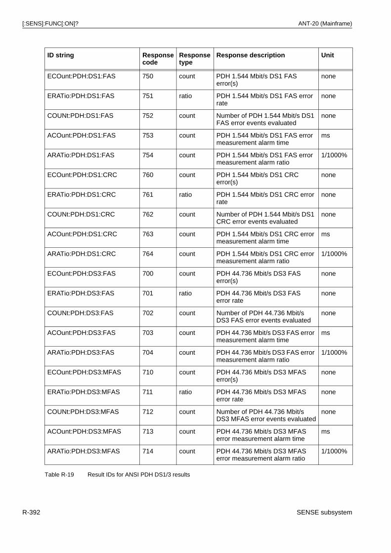
[:SENS]:FUNC[:ON]? ANT-20 (Mainframe)
ID string Responsecode
Responsetype
Response description Unit
ECOunt:PDH:DS1:FAS 750 count PDH 1.544 Mbit/s DS1 FAS error(s)
none
ERATio:PDH:DS1:FAS 751 ratio PDH 1.544 Mbit/s DS1 FAS error rate
none
COUNt:PDH:DS1:FAS 752 count Number of PDH 1.544 Mbit/s DS1 FAS error events evaluated
none
ACOunt:PDH:DS1:FAS 753 count PDH 1.544 Mbit/s DS1 FAS error measurement alarm time
ms
ARATio:PDH:DS1:FAS 754 count PDH 1.544 Mbit/s DS1 FAS error measurement alarm ratio
1/1000%
ECOunt:PDH:DS1:CRC 760 count PDH 1.544 Mbit/s DS1 CRC error(s)
none
ERATio:PDH:DS1:CRC 761 ratio PDH 1.544 Mbit/s DS1 CRC error rate
none
COUNt:PDH:DS1:CRC 762 count Number of PDH 1.544 Mbit/s DS1 CRC error events evaluated
none
ACOunt:PDH:DS1:CRC 763 count PDH 1.544 Mbit/s DS1 CRC error measurement alarm time
ms
ARATio:PDH:DS1:CRC 764 count PDH 1.544 Mbit/s DS1 CRC error measurement alarm ratio
1/1000%
ECOunt:PDH:DS3:FAS 700 count PDH 44.736 Mbit/s DS3 FASerror(s)
none
ERATio:PDH:DS3:FAS 701 ratio PDH 44.736 Mbit/s DS3 FASerror rate
none
COUNt:PDH:DS3:FAS 702 count Number of PDH 44.736 Mbit/s DS3 FAS error events evaluated
none
ACOunt:PDH:DS3:FAS 703 count PDH 44.736 Mbit/s DS3 FAS error measurement alarm time
ms
ARATio:PDH:DS3:FAS 704 count PDH 44.736 Mbit/s DS3 FAS error measurement alarm ratio
1/1000%
ECOunt:PDH:DS3:MFAS 710 count PDH 44.736 Mbit/s DS3 MFAS error(s)
none
ERATio:PDH:DS3:MFAS 711 ratio PDH 44.736 Mbit/s DS3 MFAS error rate
none
COUNt:PDH:DS3:MFAS 712 count Number of PDH 44.736 Mbit/s DS3 MFAS error events evaluated
none
ACOunt:PDH:DS3:MFAS 713 count PDH 44.736 Mbit/s DS3 MFAS error measurement alarm time
ms
ARATio:PDH:DS3:MFAS 714 count PDH 44.736 Mbit/s DS3 MFAS error measurement alarm ratio
1/1000%
Table R-19 Result IDs for ANSI PDH DS1/3 results
R-392 SENSE subsystem
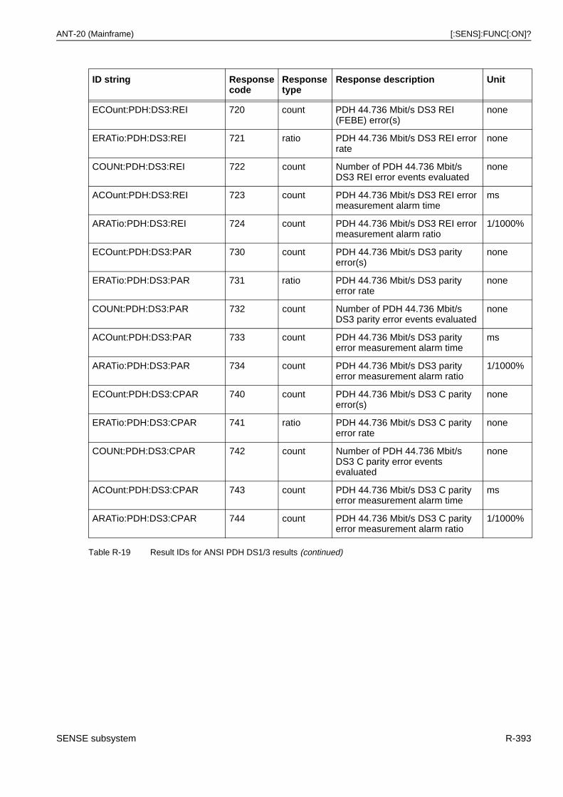
ANT-20 (Mainframe) [:SENS]:FUNC[:ON]?
ECOunt:PDH:DS3:REI 720 count PDH 44.736 Mbit/s DS3 REI (FEBE) error(s)
none
ERATio:PDH:DS3:REI 721 ratio PDH 44.736 Mbit/s DS3 REI error rate
none
COUNt:PDH:DS3:REI 722 count Number of PDH 44.736 Mbit/s DS3 REI error events evaluated
none
ACOunt:PDH:DS3:REI 723 count PDH 44.736 Mbit/s DS3 REI error measurement alarm time
ms
ARATio:PDH:DS3:REI 724 count PDH 44.736 Mbit/s DS3 REI error measurement alarm ratio
1/1000%
ECOunt:PDH:DS3:PAR 730 count PDH 44.736 Mbit/s DS3 parity error(s)
none
ERATio:PDH:DS3:PAR 731 ratio PDH 44.736 Mbit/s DS3 parity error rate
none
COUNt:PDH:DS3:PAR 732 count Number of PDH 44.736 Mbit/s DS3 parity error events evaluated
none
ACOunt:PDH:DS3:PAR 733 count PDH 44.736 Mbit/s DS3 parity error measurement alarm time
ms
ARATio:PDH:DS3:PAR 734 count PDH 44.736 Mbit/s DS3 parity error measurement alarm ratio
1/1000%
ECOunt:PDH:DS3:CPAR 740 count PDH 44.736 Mbit/s DS3 C parity error(s)
none
ERATio:PDH:DS3:CPAR 741 ratio PDH 44.736 Mbit/s DS3 C parity error rate
none
COUNt:PDH:DS3:CPAR 742 count Number of PDH 44.736 Mbit/s DS3 C parity error events evaluated
none
ACOunt:PDH:DS3:CPAR 743 count PDH 44.736 Mbit/s DS3 C parity error measurement alarm time
ms
ARATio:PDH:DS3:CPAR 744 count PDH 44.736 Mbit/s DS3 C parity error measurement alarm ratio
1/1000%
ID string Responsecode
Responsetype
Response description Unit
Table R-19 Result IDs for ANSI PDH DS1/3 results (continued)
SENSE subsystem R-393
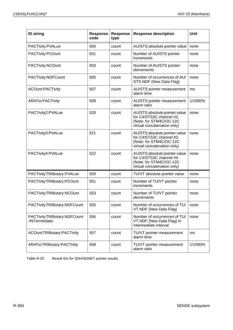
[:SENS]:FUNC[:ON]? ANT-20 (Mainframe)
ID string Responsecode
Responsetype
Response description Unit
PACTivity:PVALue 500 count AU/STS absolute pointer value none
PACTivity:PCOunt 501 count Number of AU/STS pointer increments
none
PACTivity:NCOunt 503 count Number of AU/STS pointer decrements
none
PACTivity:NDFCount 505 count Number of occurrences of AU/STS NDF (New Data Flag)
none
ACOunt:PACTivity 507 count AU/STS pointer measurement alarm time
ms
ARATio:PACTivity 508 count AU/STS pointer measurement alarm ratio
1/1000%
PACTivity2:PVALue 520 count AU/STS absolute pointer value for C4/STS3C channel #2.(Note: for STM4C/OC-12C virtual concatenation only)
none
PACTivity3:PVALue 521 count AU/STS absolute pointer value for C4/STS3C channel #3.(Note: for STM4C/OC-12C virtual concatenation only)
none
PACTivity4:PVALue 522 count AU/STS absolute pointer value for C4/STS3C channel #4.(Note: for STM4C/OC-12C virtual concatenation only)
none
PACTivity:TRIButary:PVALue 550 count TU/VT absolute pointer value none
PACTivity:TRIButary:PCOunt 551 count Number of TU/VT pointer increments
none
PACTivity:TRIButary:NCOunt 553 count Number of TU/VT pointer decrements
none
PACTivity:TRIButary:NDFCount 555 count Number of occurrences of TU/VT NDF (New Data Flag)
none
PACTivity:TRIButary:NDFCount:INTermediate
556 count Number of occurrences of TU/VT NDF (New Data Flag) in intermediate interval
none
ACOunt:TRIButary:PACTivity 557 count TU/VT pointer measurement alarm time
ms
ARATio:TRIButary:PACTivity 558 count TU/VT pointer measurement alarm ratio
1/1000%
Table R-20 Result IDs for SDH/SONET pointer results
R-394 SENSE subsystem
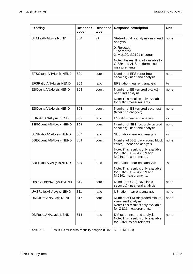
ANT-20 (Mainframe) [:SENS]:FUNC[:ON]?
ID string Responsecode
Responsetype
Response description Unit
STATe:ANALysis:NEND 800 int State of quality analysis - near end analysis
0: Rejected1: Accepted2: M.2100/M.2101 uncertain
Note: This result is not available for G.829 and ANSI performance measurements.
none
EFSCount:ANALysis:NEND 801 count Number of EFS (error free seconds) - near end analysis
none
EFSRatio:ANALysis:NEND 802 ratio EFS ratio - near end analysis %
EBCount:ANALysis:NEND 803 count Number of EB (errored blocks) - near end analysis
Note: This result is only available for G.826 measurements.
none
ESCount:ANALysis:NEND 804 count Number of ES (errored seconds) (Near end analysis)
none
ESRatio:ANALysis:NEND 805 ratio ES ratio - near end analysis %
SESCount:ANALysis:NEND 806 count Number of SES (severely errored seconds) - near end analysis
none
SESRatio:ANALysis:NEND 807 ratio SES ratio - near end analysis %
BBECount:ANALysis:NEND 808 count Number of BBE (background block errors) - near end analysis
Note: This result is only available for G.826/G.828/G.829 and M.2101 measurements.
none
BBERatio:ANALysis:NEND 809 ratio BBE ratio - near end analysis
Note: This result is only available for G.826/G.828/G.829 and M.2101 measurements.
%
UASCount:ANALysis:NEND 810 count Number of US (unavailable seconds) - near end analysis
none
UASRatio:ANALysis:NEND 811 ratio US ratio - near end analysis none
DMCount:ANALysis:NEND 812 count Number of DM (degraded minute) - near end analysisNote: This result is only available for G.821 measurements.
none
DMRatio:ANALysis:NEND 813 ratio DM ratio - near end analysisNote: This result is only available for G.821 measurements.
none
Table R-21 Result IDs for results of quality analysis (G.826, G.821, M21.00)
SENSE subsystem R-395
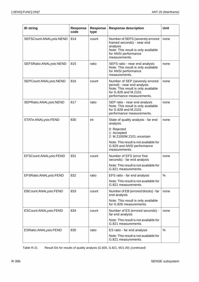
[:SENS]:FUNC[:ON]? ANT-20 (Mainframe)
SEFSCount:ANALysis:NEND 814 count Number of SEFS (severely errored framed seconds) - near end analysisNote: This result is only available for ANSI performance measurements.
none
SEFSRatio:ANALysis:NEND 815 ratio SEFS ratio - near end analysisNote: This result is only available for ANSI performance measurements.
none
SEPCount:ANALysis:NEND 816 count Number of SEP (severely errored period) - near end analysisNote: This result is only available for G.828 and M.2101 performance measurements.
none
SEPRatio:ANALysis:NEND 817 ratio SEP ratio - near end analysisNote: This result is only available for G.828 and M.2101 performance measurements.
none
STATe:ANALysis:FEND 830 int State of quality analysis - far end analysis
0: Rejected1: Accepted2: M.2100/M.2101 uncertain
Note: This result is not available for G.829 and ANSI performance measurements.
none
EFSCount:ANALysis:FEND 831 count Number of EFS (error free seconds) - far end analysis
Note: This result is not available for G.821 measurements.
none
EFSRatio:ANALysis:FEND 832 ratio EFS ratio - far end analysis
Note: This result is not available for G.821 measurements.
%
EBCount:ANALysis:FEND 833 count Number of EB (errored blocks) - far end analysis
Note: This result is only available for G.826 measurements.
none
ESCount:ANALysis:FEND 834 count Number of ES (errored seconds) - far end analysis
Note: This result is not available for G.821 measurements.
none
ESRatio:ANALysis:FEND 835 ratio ES ratio - far end analysis
Note: This result is not available for G.821 measurements.
%
ID string Responsecode
Responsetype
Response description Unit
Table R-21 Result IDs for results of quality analysis (G.826, G.821, M21.00) (continued)
R-396 SENSE subsystem
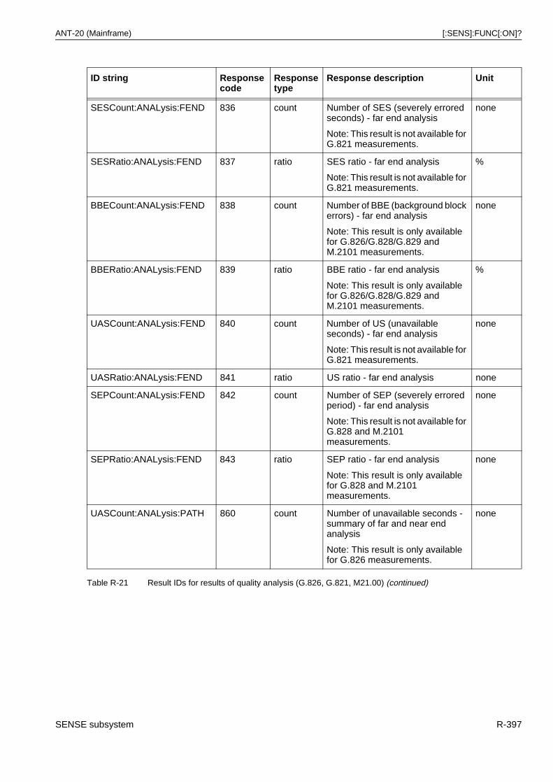
ANT-20 (Mainframe) [:SENS]:FUNC[:ON]?
SESCount:ANALysis:FEND 836 count Number of SES (severely errored seconds) - far end analysis
Note: This result is not available for G.821 measurements.
none
SESRatio:ANALysis:FEND 837 ratio SES ratio - far end analysis
Note: This result is not available for G.821 measurements.
%
BBECount:ANALysis:FEND 838 count Number of BBE (background block errors) - far end analysis
Note: This result is only available for G.826/G.828/G.829 and M.2101 measurements.
none
BBERatio:ANALysis:FEND 839 ratio BBE ratio - far end analysis
Note: This result is only available for G.826/G.828/G.829 and M.2101 measurements.
%
UASCount:ANALysis:FEND 840 count Number of US (unavailable seconds) - far end analysis
Note: This result is not available for G.821 measurements.
none
UASRatio:ANALysis:FEND 841 ratio US ratio - far end analysis none
SEPCount:ANALysis:FEND 842 count Number of SEP (severely errored period) - far end analysis
Note: This result is not available for G.828 and M.2101 measurements.
none
SEPRatio:ANALysis:FEND 843 ratio SEP ratio - far end analysis
Note: This result is only available for G.828 and M.2101 measurements.
none
UASCount:ANALysis:PATH 860 count Number of unavailable seconds - summary of far and near end analysis
Note: This result is only available for G.826 measurements.
none
ID string Responsecode
Responsetype
Response description Unit
Table R-21 Result IDs for results of quality analysis (G.826, G.821, M21.00) (continued)
SENSE subsystem R-397
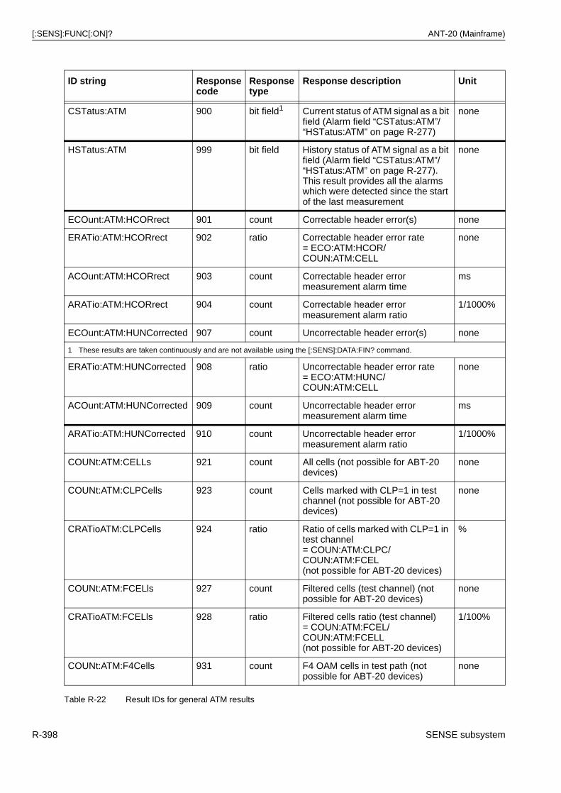
[:SENS]:FUNC[:ON]? ANT-20 (Mainframe)
ID string Responsecode
Responsetype
Response description Unit
CSTatus:ATM 900 bit field1 Current status of ATM signal as a bit field (Alarm field “CSTatus:ATM”/“HSTatus:ATM” on page R-277)
none
HSTatus:ATM 999 bit field History status of ATM signal as a bit field (Alarm field “CSTatus:ATM”/“HSTatus:ATM” on page R-277). This result provides all the alarms which were detected since the start of the last measurement
none
ECOunt:ATM:HCORrect 901 count Correctable header error(s) none
ERATio:ATM:HCORrect 902 ratio Correctable header error rate= ECO:ATM:HCOR/COUN:ATM:CELL
none
ACOunt:ATM:HCORrect 903 count Correctable header error measurement alarm time
ms
ARATio:ATM:HCORrect 904 count Correctable header error measurement alarm ratio
1/1000%
ECOunt:ATM:HUNCorrected 907 count Uncorrectable header error(s) none
1 These results are taken continuously and are not available using the [:SENS]:DATA:FIN? command.
ERATio:ATM:HUNCorrected 908 ratio Uncorrectable header error rate= ECO:ATM:HUNC/COUN:ATM:CELL
none
ACOunt:ATM:HUNCorrected 909 count Uncorrectable header error measurement alarm time
ms
ARATio:ATM:HUNCorrected 910 count Uncorrectable header error measurement alarm ratio
1/1000%
COUNt:ATM:CELLs 921 count All cells (not possible for ABT-20 devices)
none
COUNt:ATM:CLPCells 923 count Cells marked with CLP=1 in test channel (not possible for ABT-20 devices)
none
CRATioATM:CLPCells 924 ratio Ratio of cells marked with CLP=1 in test channel= COUN:ATM:CLPC/ COUN:ATM:FCEL(not possible for ABT-20 devices)
%
COUNt:ATM:FCELls 927 count Filtered cells (test channel) (not possible for ABT-20 devices)
none
CRATioATM:FCELls 928 ratio Filtered cells ratio (test channel)= COUN:ATM:FCEL/ COUN:ATM:FCELL(not possible for ABT-20 devices)
1/100%
COUNt:ATM:F4Cells 931 count F4 OAM cells in test path (not possible for ABT-20 devices)
none
Table R-22 Result IDs for general ATM results
R-398 SENSE subsystem
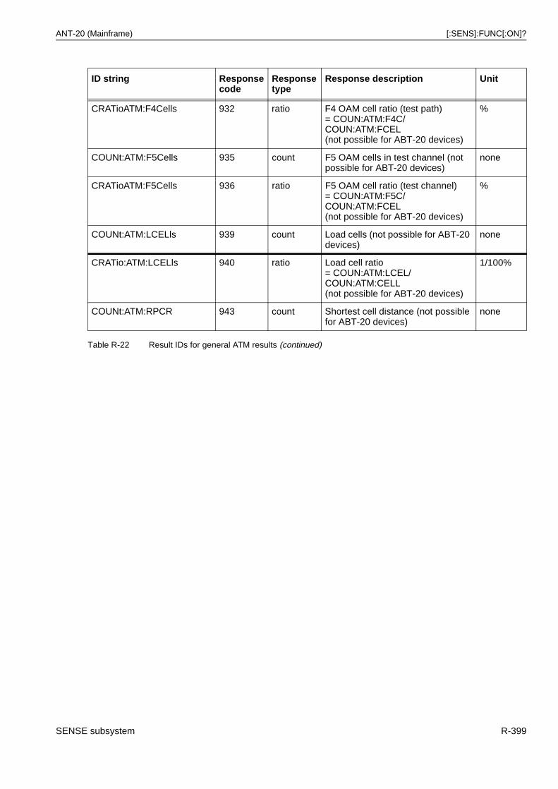
ANT-20 (Mainframe) [:SENS]:FUNC[:ON]?
CRATioATM:F4Cells 932 ratio F4 OAM cell ratio (test path)= COUN:ATM:F4C/ COUN:ATM:FCEL(not possible for ABT-20 devices)
%
COUNt:ATM:F5Cells 935 count F5 OAM cells in test channel (not possible for ABT-20 devices)
none
CRATioATM:F5Cells 936 ratio F5 OAM cell ratio (test channel)= COUN:ATM:F5C/ COUN:ATM:FCEL(not possible for ABT-20 devices)
%
COUNt:ATM:LCELls 939 count Load cells (not possible for ABT-20 devices)
none
CRATio:ATM:LCELls 940 ratio Load cell ratio= COUN:ATM:LCEL/ COUN:ATM:CELL(not possible for ABT-20 devices)
1/100%
COUNt:ATM:RPCR 943 count Shortest cell distance (not possible for ABT-20 devices)
none
ID string Responsecode
Responsetype
Response description Unit
Table R-22 Result IDs for general ATM results (continued)
SENSE subsystem R-399
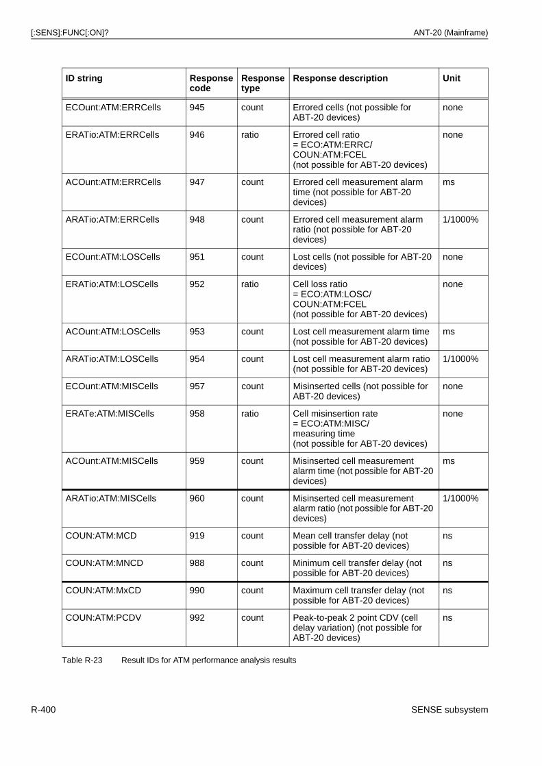
[:SENS]:FUNC[:ON]? ANT-20 (Mainframe)
ID string Responsecode
Responsetype
Response description Unit
ECOunt:ATM:ERRCells 945 count Errored cells (not possible for ABT-20 devices)
none
ERATio:ATM:ERRCells 946 ratio Errored cell ratio= ECO:ATM:ERRC/COUN:ATM:FCEL(not possible for ABT-20 devices)
none
ACOunt:ATM:ERRCells 947 count Errored cell measurement alarm time (not possible for ABT-20 devices)
ms
ARATio:ATM:ERRCells 948 count Errored cell measurement alarm ratio (not possible for ABT-20 devices)
1/1000%
ECOunt:ATM:LOSCells 951 count Lost cells (not possible for ABT-20 devices)
none
ERATio:ATM:LOSCells 952 ratio Cell loss ratio= ECO:ATM:LOSC/COUN:ATM:FCEL(not possible for ABT-20 devices)
none
ACOunt:ATM:LOSCells 953 count Lost cell measurement alarm time (not possible for ABT-20 devices)
ms
ARATio:ATM:LOSCells 954 count Lost cell measurement alarm ratio (not possible for ABT-20 devices)
1/1000%
ECOunt:ATM:MISCells 957 count Misinserted cells (not possible for ABT-20 devices)
none
ERATe:ATM:MISCells 958 ratio Cell misinsertion rate= ECO:ATM:MISC/measuring time(not possible for ABT-20 devices)
none
ACOunt:ATM:MISCells 959 count Misinserted cell measurement alarm time (not possible for ABT-20 devices)
ms
ARATio:ATM:MISCells 960 count Misinserted cell measurement alarm ratio (not possible for ABT-20 devices)
1/1000%
COUN:ATM:MCD 919 count Mean cell transfer delay (not possible for ABT-20 devices)
ns
COUN:ATM:MNCD 988 count Minimum cell transfer delay (not possible for ABT-20 devices)
ns
COUN:ATM:MxCD 990 count Maximum cell transfer delay (not possible for ABT-20 devices)
ns
COUN:ATM:PCDV 992 count Peak-to-peak 2 point CDV (cell delay variation) (not possible for ABT-20 devices)
ns
Table R-23 Result IDs for ATM performance analysis results
R-400 SENSE subsystem
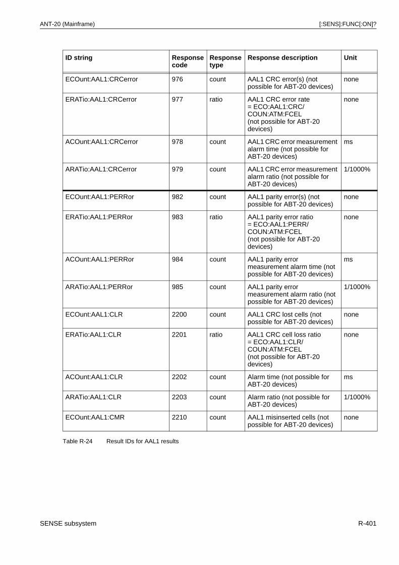
ANT-20 (Mainframe) [:SENS]:FUNC[:ON]?
ID string Responsecode
Responsetype
Response description Unit
ECOunt:AAL1:CRCerror 976 count AAL1 CRC error(s) (not possible for ABT-20 devices)
none
ERATio:AAL1:CRCerror 977 ratio AAL1 CRC error rate= ECO:AAL1:CRC/COUN:ATM:FCEL(not possible for ABT-20 devices)
none
ACOunt:AAL1:CRCerror 978 count AAL1 CRC error measurement alarm time (not possible for ABT-20 devices)
ms
ARATio:AAL1:CRCerror 979 count AAL1 CRC error measurement alarm ratio (not possible for ABT-20 devices)
1/1000%
ECOunt:AAL1:PERRor 982 count AAL1 parity error(s) (not possible for ABT-20 devices)
none
ERATio:AAL1:PERRor 983 ratio AAL1 parity error ratio= ECO:AAL1:PERR/COUN:ATM:FCEL(not possible for ABT-20 devices)
none
ACOunt:AAL1:PERRor 984 count AAL1 parity error measurement alarm time (not possible for ABT-20 devices)
ms
ARATio:AAL1:PERRor 985 count AAL1 parity error measurement alarm ratio (not possible for ABT-20 devices)
1/1000%
ECOunt:AAL1:CLR 2200 count AAL1 CRC lost cells (not possible for ABT-20 devices)
none
ERATio:AAL1:CLR 2201 ratio AAL1 CRC cell loss ratio= ECO:AAL1:CLR/COUN:ATM:FCEL(not possible for ABT-20 devices)
none
ACOunt:AAL1:CLR 2202 count Alarm time (not possible for ABT-20 devices)
ms
ARATio:AAL1:CLR 2203 count Alarm ratio (not possible for ABT-20 devices)
1/1000%
ECOunt:AAL1:CMR 2210 count AAL1 misinserted cells (not possible for ABT-20 devices)
none
Table R-24 Result IDs for AAL1 results
SENSE subsystem R-401
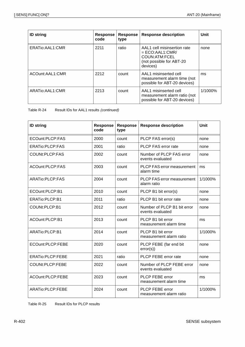
[:SENS]:FUNC[:ON]? ANT-20 (Mainframe)
ERATio:AAL1:CMR 2211 ratio AAL1 cell misinsertion rate= ECO:AAL1:CMR/COUN:ATM:FCEL(not possible for ABT-20 devices)
none
ACOunt:AAL1:CMR 2212 count AAL1 misinserted cell measurement alarm time (not possible for ABT-20 devices)
ms
ARATio:AAL1:CMR 2213 count AAL1 misinserted cell measurement alarm ratio (not possible for ABT-20 devices)
1/1000%
ID string Responsecode
Responsetype
Response description Unit
ECOunt:PLCP:FAS 2000 count PLCP FAS error(s) none
ERATio:PLCP:FAS 2001 ratio PLCP FAS error rate none
COUNt:PLCP:FAS 2002 count Number of PLCP FAS error events evaluated
none
ACOunt:PLCP:FAS 2003 count PLCP FAS error measurement alarm time
ms
ARATio:PLCP:FAS 2004 count PLCP FAS error measurement alarm ratio
1/1000%
ECOunt:PLCP:B1 2010 count PLCP B1 bit error(s) none
ERATio:PLCP:B1 2011 ratio PLCP B1 bit error rate none
COUNt:PLCP:B1 2012 count Number of PLCP B1 bit error events evaluated
none
ACOunt:PLCP:B1 2013 count PLCP B1 bit error measurement alarm time
ms
ARATio:PLCP:B1 2014 count PLCP B1 bit error measurement alarm ratio
1/1000%
ECOunt:PLCP:FEBE 2020 count PLCP FEBE (far end bit error(s))
none
ERATio:PLCP:FEBE 2021 ratio PLCP FEBE error rate none
COUNt:PLCP:FEBE 2022 count Number of PLCP FEBE error events evaluated
none
ACOunt:PLCP:FEBE 2023 count PLCP FEBE error measurement alarm time
ms
ARATio:PLCP:FEBE 2024 count PLCP FEBE error measurement alarm ratio
1/1000%
Table R-25 Result IDs for PLCP results
ID string Responsecode
Responsetype
Response description Unit
Table R-24 Result IDs for AAL1 results (continued)
R-402 SENSE subsystem
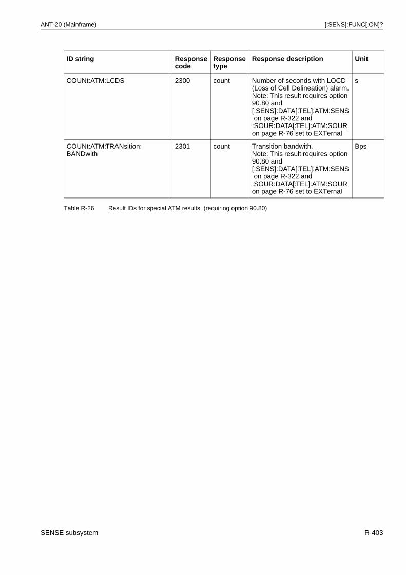
ANT-20 (Mainframe) [:SENS]:FUNC[:ON]?
ID string Responsecode
Responsetype
Response description Unit
COUNt:ATM:LCDS 2300 count Number of seconds with LOCD (Loss of Cell Delineation) alarm.Note: This result requires option 90.80 and [:SENS]:DATA[:TEL]:ATM:SENSon page R-322 and :SOUR:DATA[:TEL]:ATM:SOURon page R-76 set to EXTernal
s
COUNt:ATM:TRANsition:BANDwith
2301 count Transition bandwith.Note: This result requires option 90.80 and [:SENS]:DATA[:TEL]:ATM:SENSon page R-322 and :SOUR:DATA[:TEL]:ATM:SOURon page R-76 set to EXTernal
Bps
Table R-26 Result IDs for special ATM results (requiring option 90.80)
SENSE subsystem R-403
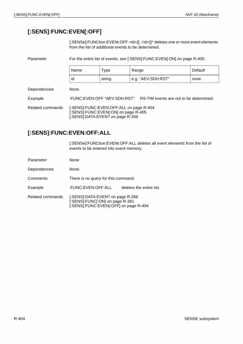
[:SENS]:FUNC:EVEN[:OFF] ANT-20 (Mainframe)
[:SENS]:FUNC:EVEN[:OFF]
[:SENSe]:FUNCtion:EVENt:OFF <id>{[, <id>]}* deletes one or more event elements from the list of additional events to be determined.
[:SENS]:FUNC:EVEN:OFF:ALL
[:SENSe]:FUNCtion:EVENt:OFF:ALL deletes all event elements from the list of events to be entered into event memory.
Parameter For the entire list of events, see [:SENS]:FUNC:EVEN[:ON] on page R-405.
Name Type Range Default
id string e.g. “AEV:SDH:RST” none
Dependencies None
Example :FUNC:EVEN:OFF “AEV:SDH:RST” RS-TIM events are not to be determined.
Related commands [:SENS]:FUNC:EVEN:OFF:ALL on page R-404[:SENS]:FUNC:EVEN[:ON] on page R-405[:SENS]:DATA:EVEN? on page R-266
Parameter None
Dependencies None
Comments There is no query for this command.
Example :FUNC:EVEN:OFF:ALL deletes the entire list.
Related commands [:SENS]:DATA:EVEN? on page R-266[:SENS]:FUNC[:ON] on page R-381[:SENS]:FUNC:EVEN[:OFF] on page R-404
R-404 SENSE subsystem
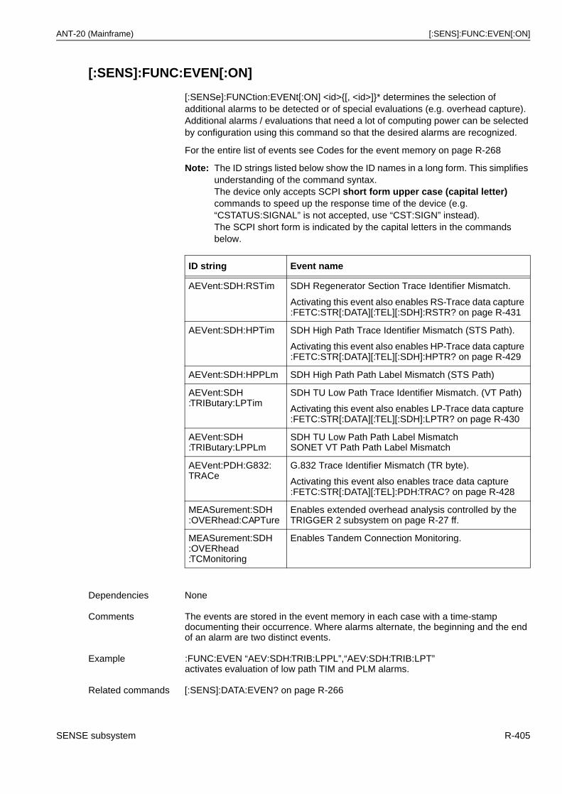
ANT-20 (Mainframe) [:SENS]:FUNC:EVEN[:ON]
[:SENS]:FUNC:EVEN[:ON]
[:SENSe]:FUNCtion:EVENt[:ON] <id>{[, <id>]}* determines the selection of additional alarms to be detected or of special evaluations (e.g. overhead capture).Additional alarms / evaluations that need a lot of computing power can be selected by configuration using this command so that the desired alarms are recognized.
For the entire list of events see Codes for the event memory on page R-268
Note: The ID strings listed below show the ID names in a long form. This simplifies understanding of the command syntax.The device only accepts SCPI short form upper case (capital letter) commands to speed up the response time of the device (e.g. “CSTATUS:SIGNAL” is not accepted, use “CST:SIGN” instead).The SCPI short form is indicated by the capital letters in the commands below.
ID string Event name
AEVent:SDH:RSTim SDH Regenerator Section Trace Identifier Mismatch.
Activating this event also enables RS-Trace data capture :FETC:STR[:DATA][:TEL][:SDH]:RSTR? on page R-431
AEVent:SDH:HPTim SDH High Path Trace Identifier Mismatch (STS Path).
Activating this event also enables HP-Trace data capture :FETC:STR[:DATA][:TEL][:SDH]:HPTR? on page R-429
AEVent:SDH:HPPLm SDH High Path Path Label Mismatch (STS Path)
AEVent:SDH:TRIButary:LPTim
SDH TU Low Path Trace Identifier Mismatch. (VT Path)
Activating this event also enables LP-Trace data capture :FETC:STR[:DATA][:TEL][:SDH]:LPTR? on page R-430
AEVent:SDH:TRIButary:LPPLm
SDH TU Low Path Path Label MismatchSONET VT Path Path Label Mismatch
AEVent:PDH:G832:TRACe
G.832 Trace Identifier Mismatch (TR byte).
Activating this event also enables trace data capture :FETC:STR[:DATA][:TEL]:PDH:TRAC? on page R-428
MEASurement:SDH:OVERhead:CAPTure
Enables extended overhead analysis controlled by the TRIGGER 2 subsystem on page R-27 ff.
MEASurement:SDH:OVERhead:TCMonitoring
Enables Tandem Connection Monitoring.
Dependencies None
Comments The events are stored in the event memory in each case with a time-stamp documenting their occurrence. Where alarms alternate, the beginning and the end of an alarm are two distinct events.
Example :FUNC:EVEN “AEV:SDH:TRIB:LPPL”,“AEV:SDH:TRIB:LPT”activates evaluation of low path TIM and PLM alarms.
Related commands [:SENS]:DATA:EVEN? on page R-266
SENSE subsystem R-405
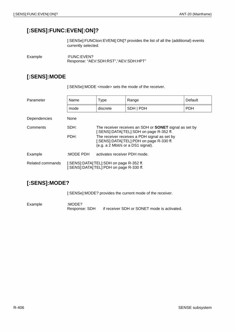
[:SENS]:FUNC:EVEN[:ON]? ANT-20 (Mainframe)
[:SENS]:FUNC:EVEN[:ON]?
[:SENSe]:FUNCtion:EVENt[:ON]? provides the list of all the (additional) events currently selected.
[:SENS]:MODE
[:SENSe]:MODE <mode> sets the mode of the receiver.
[:SENS]:MODE?
[:SENSe]:MODE? provides the current mode of the receiver.
Example :FUNC:EVEN?Response: “AEV:SDH:RST”,“AEV:SDH:HPT”
Parameter Name Type Range Default
mode discrete SDH | PDH PDH
Dependencies None
Comments SDH: The receiver receives an SDH or SONET signal as set by [:SENS]:DATA[:TEL]:SDH on page R-352 ff.
PDH: The receiver receives a PDH signal as set by [:SENS]:DATA[:TEL]:PDH on page R-330 ff.(e.g. a 2 Mbit/s or a DS1 signal).
Example :MODE PDH activates receiver PDH mode.
Related commands [:SENS]:DATA[:TEL]:SDH on page R-352 ff.[:SENS]:DATA[:TEL]:PDH on page R-330 ff.
Example :MODE?Response: SDH if receiver SDH or SONET mode is activated.
R-406 SENSE subsystem
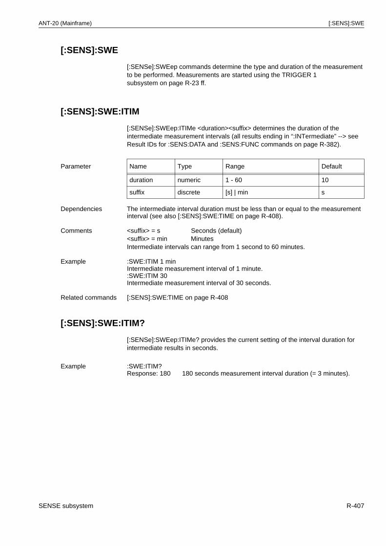
ANT-20 (Mainframe) [:SENS]:SWE
[:SENS]:SWE
[:SENSe]:SWEep commands determine the type and duration of the measurement to be performed. Measurements are started using the TRIGGER 1 subsystem on page R-23 ff.
[:SENS]:SWE:ITIM
[:SENSe]:SWEep:ITIMe <duration><suffix> determines the duration of the intermediate measurement intervals (all results ending in “:INTermediate” --> see Result IDs for :SENS:DATA and :SENS:FUNC commands on page R-382).
[:SENS]:SWE:ITIM?
[:SENSe]:SWEep:ITIMe? provides the current setting of the interval duration for intermediate results in seconds.
Parameter Name Type Range Default
duration numeric 1 - 60 10
suffix discrete [s] | min s
Dependencies The intermediate interval duration must be less than or equal to the measurement interval (see also [:SENS]:SWE:TIME on page R-408).
Comments <suffix> = s Seconds (default)<suffix> = min MinutesIntermediate intervals can range from 1 second to 60 minutes.
Example :SWE:ITIM 1 minIntermediate measurement interval of 1 minute.:SWE:ITIM 30Intermediate measurement interval of 30 seconds.
Related commands [:SENS]:SWE:TIME on page R-408
Example :SWE:ITIM?Response: 180 180 seconds measurement interval duration (= 3 minutes).
SENSE subsystem R-407
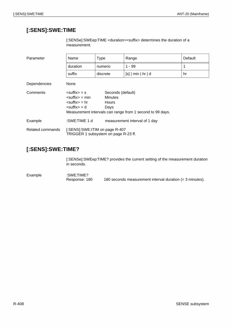
[:SENS]:SWE:TIME ANT-20 (Mainframe)
[:SENS]:SWE:TIME
[:SENSe]:SWEep:TIME <duration><suffix> determines the duration of a measurement.
[:SENS]:SWE:TIME?
[:SENSe]:SWEep:TIME? provides the current setting of the measurement duration in seconds.
Parameter Name Type Range Default
duration numeric 1 - 99 1
suffix discrete [s] | min | hr | d hr
Dependencies None
Comments <suffix> = s Seconds (default)<suffix> = min Minutes<suffix> = hr Hours<suffix> = d DaysMeasurement intervals can range from 1 second to 99 days.
Example :SWE:TIME 1 d measurement interval of 1 day
Related commands [:SENS]:SWE:ITIM on page R-407TRIGGER 1 subsystem on page R-23 ff.
Example :SWE:TIME?Response: 180 180 seconds measurement interval duration (= 3 minutes).
R-408 SENSE subsystem
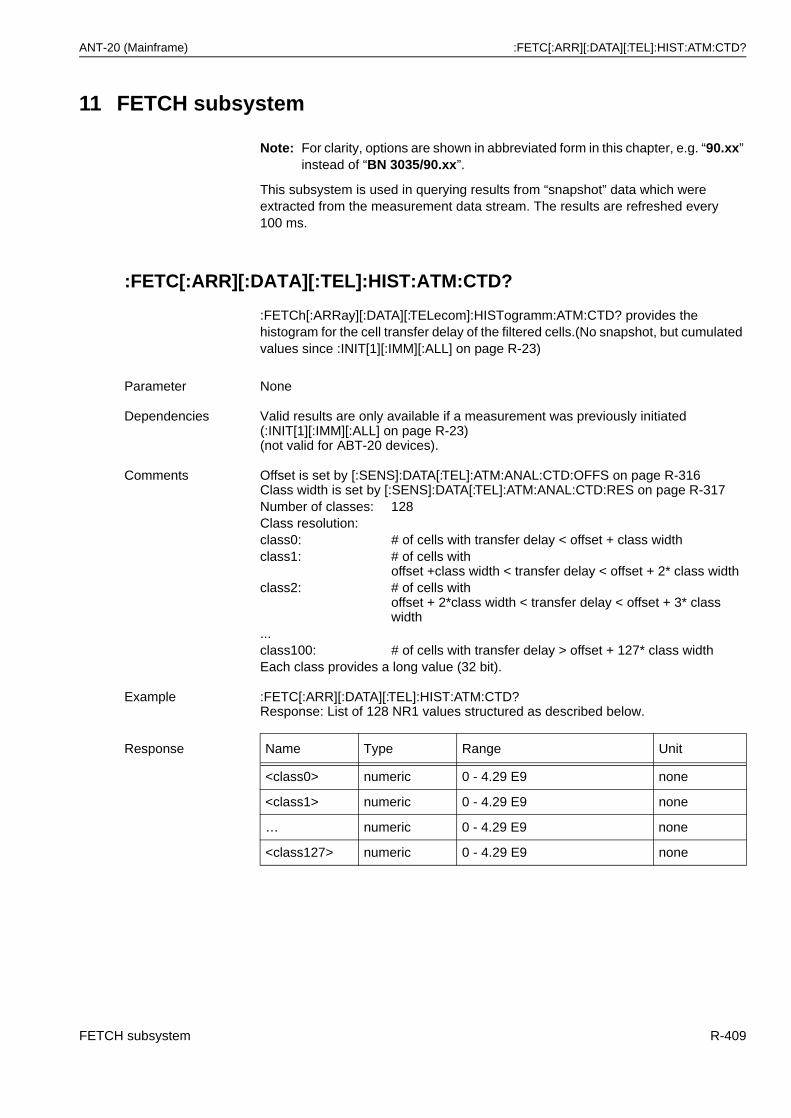
ANT-20 (Mainframe) :FETC[:ARR][:DATA][:TEL]:HIST:ATM:CTD?
11 FETCH subsystem
Note: For clarity, options are shown in abbreviated form in this chapter, e.g. “90.xx” instead of “BN 3035/90.xx”.
This subsystem is used in querying results from “snapshot” data which were extracted from the measurement data stream. The results are refreshed every 100 ms.
:FETC[:ARR][:DATA][:TEL]:HIST:ATM:CTD?
:FETCh[:ARRay][:DATA][:TELecom]:HISTogramm:ATM:CTD? provides the histogram for the cell transfer delay of the filtered cells.(No snapshot, but cumulated values since :INIT[1][:IMM][:ALL] on page R-23)
Parameter None
Dependencies Valid results are only available if a measurement was previously initiated (:INIT[1][:IMM][:ALL] on page R-23) (not valid for ABT-20 devices).
Comments Offset is set by [:SENS]:DATA[:TEL]:ATM:ANAL:CTD:OFFS on page R-316Class width is set by [:SENS]:DATA[:TEL]:ATM:ANAL:CTD:RES on page R-317Number of classes: 128Class resolution:class0: # of cells with transfer delay < offset + class widthclass1: # of cells with
offset +class width < transfer delay < offset + 2* class widthclass2: # of cells with
offset + 2*class width < transfer delay < offset + 3* class width
...class100: # of cells with transfer delay > offset + 127* class widthEach class provides a long value (32 bit).
Example :FETC[:ARR][:DATA][:TEL]:HIST:ATM:CTD?Response: List of 128 NR1 values structured as described below.
Response Name Type Range Unit
<class0> numeric 0 - 4.29 E9 none
<class1> numeric 0 - 4.29 E9 none
… numeric 0 - 4.29 E9 none
<class127> numeric 0 - 4.29 E9 none
FETCH subsystem R-409
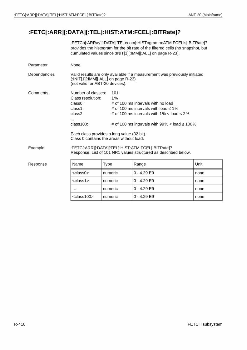
:FETC[:ARR][:DATA][:TEL]:HIST:ATM:FCEL[:BITRate]? ANT-20 (Mainframe)
:FETC[:ARR][:DATA][:TEL]:HIST:ATM:FCEL[:BITRate]?
:FETCh[:ARRay][:DATA][:TELecom]:HISTogramm:ATM:FCELls[:BITRate]? provides the histogram for the bit rate of the filtered cells (no snapshot, but cumulated values since :INIT[1][:IMM][:ALL] on page R-23).
Parameter None
Dependencies Valid results are only available if a measurement was previously initiated (:INIT[1][:IMM][:ALL] on page R-23) (not valid for ABT-20 devices).
Comments Number of classes: 101Class resolution: 1%class0: # of 100 ms intervals with no loadclass1: # of 100 ms intervals with load ≤ 1%class2: # of 100 ms intervals with 1% < load ≤ 2%...class100: # of 100 ms intervals with 99% < load ≤ 100%
Each class provides a long value (32 bit).Class 0 contains the areas without load.
Example :FETC[:ARR][:DATA][:TEL]:HIST:ATM:FCEL[:BITRate]?Response: List of 101 NR1 values structured as described below.
Response Name Type Range Unit
<class0> numeric 0 - 4.29 E9 none
<class1> numeric 0 - 4.29 E9 none
… numeric 0 - 4.29 E9 none
<class100> numeric 0 - 4.29 E9 none
R-410 FETCH subsystem
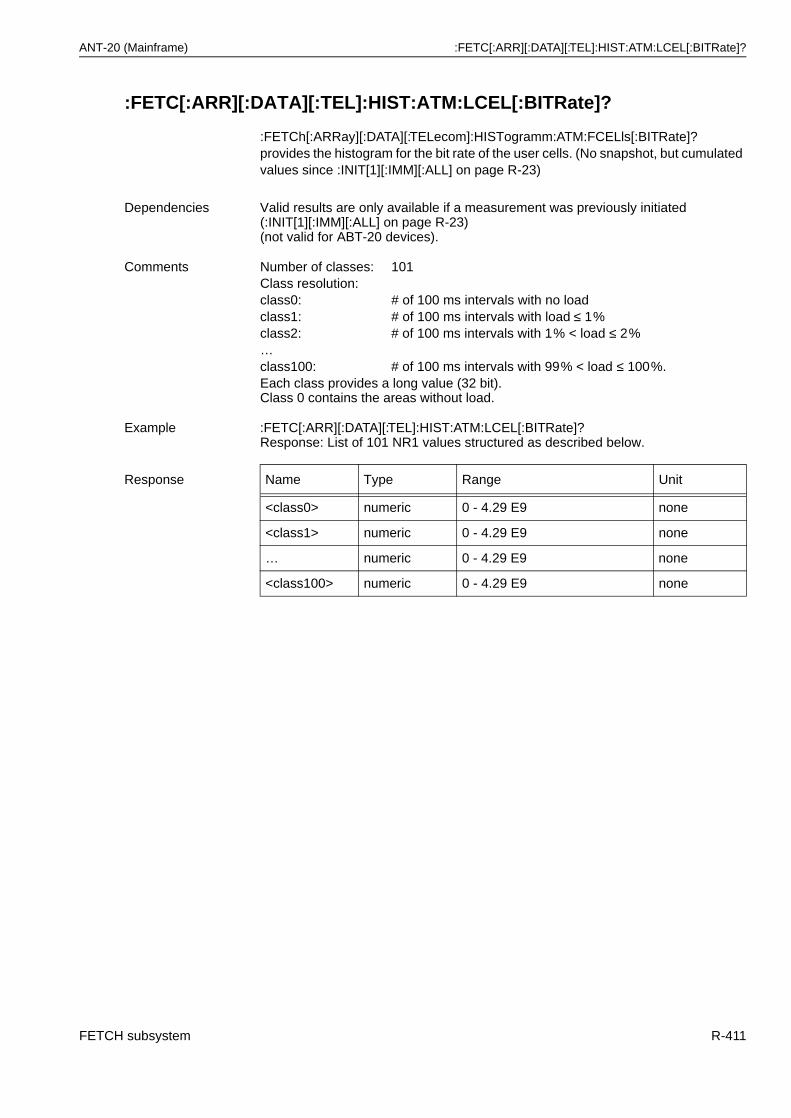
ANT-20 (Mainframe) :FETC[:ARR][:DATA][:TEL]:HIST:ATM:LCEL[:BITRate]?
:FETC[:ARR][:DATA][:TEL]:HIST:ATM:LCEL[:BITRate]?
:FETCh[:ARRay][:DATA][:TELecom]:HISTogramm:ATM:FCELls[:BITRate]? provides the histogram for the bit rate of the user cells. (No snapshot, but cumulated values since :INIT[1][:IMM][:ALL] on page R-23)
Dependencies Valid results are only available if a measurement was previously initiated (:INIT[1][:IMM][:ALL] on page R-23) (not valid for ABT-20 devices).
Comments Number of classes: 101Class resolution:class0: # of 100 ms intervals with no loadclass1: # of 100 ms intervals with load ≤ 1%class2: # of 100 ms intervals with 1% < load ≤ 2%…class100: # of 100 ms intervals with 99% < load ≤ 100%.Each class provides a long value (32 bit).Class 0 contains the areas without load.
Example :FETC[:ARR][:DATA][:TEL]:HIST:ATM:LCEL[:BITRate]?Response: List of 101 NR1 values structured as described below.
Response Name Type Range Unit
<class0> numeric 0 - 4.29 E9 none
<class1> numeric 0 - 4.29 E9 none
… numeric 0 - 4.29 E9 none
<class100> numeric 0 - 4.29 E9 none
FETCH subsystem R-411
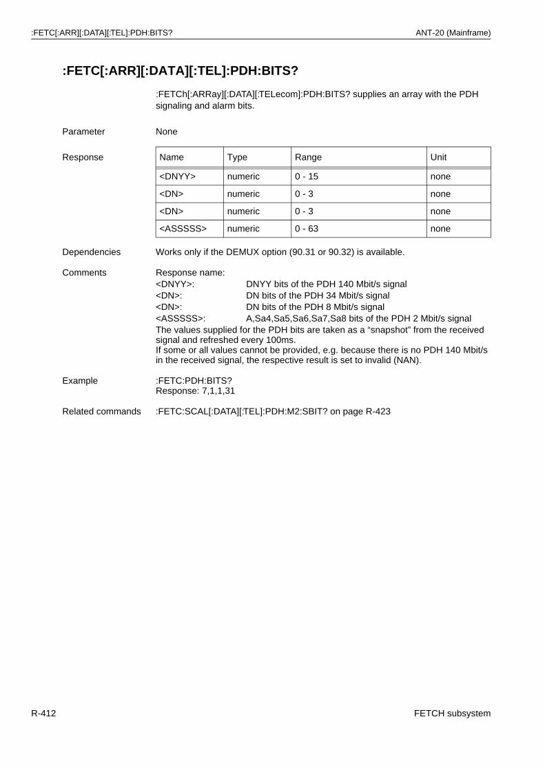
:FETC[:ARR][:DATA][:TEL]:PDH:BITS? ANT-20 (Mainframe)
:FETC[:ARR][:DATA][:TEL]:PDH:BITS?
:FETCh[:ARRay][:DATA][:TELecom]:PDH:BITS? supplies an array with the PDH signaling and alarm bits.
Parameter None
Response Name Type Range Unit
<DNYY> numeric 0 - 15 none
<DN> numeric 0 - 3 none
<DN> numeric 0 - 3 none
<ASSSSS> numeric 0 - 63 none
Dependencies Works only if the DEMUX option (90.31 or 90.32) is available.
Comments Response name:<DNYY>: DNYY bits of the PDH 140 Mbit/s signal<DN>: DN bits of the PDH 34 Mbit/s signal<DN>: DN bits of the PDH 8 Mbit/s signal<ASSSSS>: A,Sa4,Sa5,Sa6,Sa7,Sa8 bits of the PDH 2 Mbit/s signalThe values supplied for the PDH bits are taken as a “snapshot” from the received signal and refreshed every 100ms.If some or all values cannot be provided, e.g. because there is no PDH 140 Mbit/s in the received signal, the respective result is set to invalid (NAN).
Example :FETC:PDH:BITS?Response: 7,1,1,31
Related commands :FETC:SCAL[:DATA][:TEL]:PDH:M2:SBIT? on page R-423
R-412 FETCH subsystem
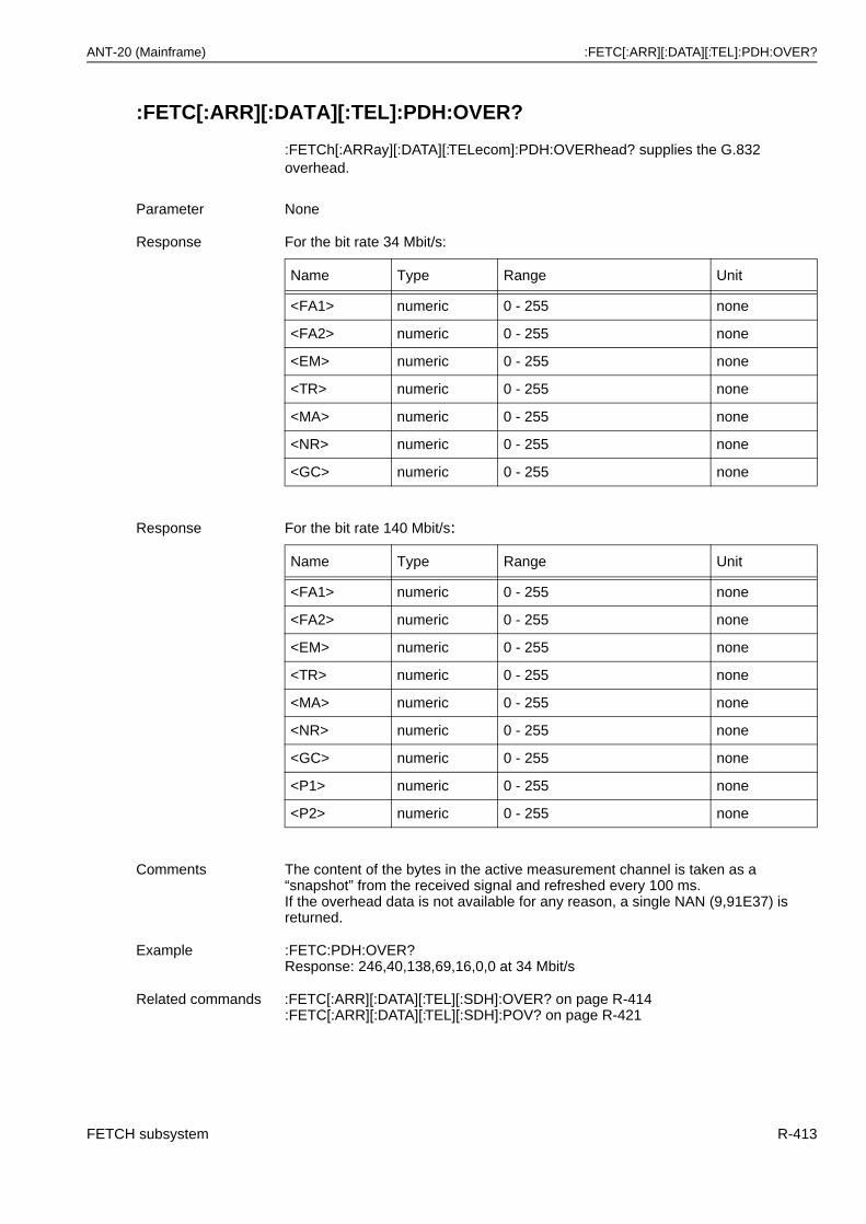
ANT-20 (Mainframe) :FETC[:ARR][:DATA][:TEL]:PDH:OVER?
:FETC[:ARR][:DATA][:TEL]:PDH:OVER?
:FETCh[:ARRay][:DATA][:TELecom]:PDH:OVERhead? supplies the G.832 overhead.
Parameter None
Response For the bit rate 34 Mbit/s:
Name Type Range Unit
<FA1> numeric 0 - 255 none
<FA2> numeric 0 - 255 none
<EM> numeric 0 - 255 none
<TR> numeric 0 - 255 none
<MA> numeric 0 - 255 none
<NR> numeric 0 - 255 none
<GC> numeric 0 - 255 none
Response For the bit rate 140 Mbit/s:
Name Type Range Unit
<FA1> numeric 0 - 255 none
<FA2> numeric 0 - 255 none
<EM> numeric 0 - 255 none
<TR> numeric 0 - 255 none
<MA> numeric 0 - 255 none
<NR> numeric 0 - 255 none
<GC> numeric 0 - 255 none
<P1> numeric 0 - 255 none
<P2> numeric 0 - 255 none
Comments The content of the bytes in the active measurement channel is taken as a “snapshot” from the received signal and refreshed every 100 ms.If the overhead data is not available for any reason, a single NAN (9,91E37) is returned.
Example :FETC:PDH:OVER?Response: 246,40,138,69,16,0,0 at 34 Mbit/s
Related commands :FETC[:ARR][:DATA][:TEL][:SDH]:OVER? on page R-414:FETC[:ARR][:DATA][:TEL][:SDH]:POV? on page R-421
FETCH subsystem R-413
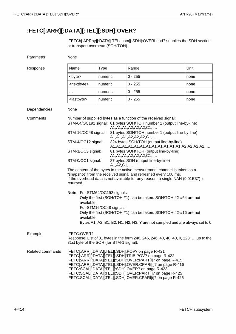
:FETC[:ARR][:DATA][:TEL][:SDH]:OVER? ANT-20 (Mainframe)
:FETC[:ARR][:DATA][:TEL][:SDH]:OVER?
:FETCh[:ARRay][:DATA][:TELecom][:SDH]:OVERhead? supplies the SDH section or transport overhead (SOH/TOH).
Note: For STM64/OC192 signals:Only the first (SOH/TOH #1) can be taken. SOH/TOH #2-#64 are not available.For STM16/OC48 signals:Only the first (SOH/TOH #1) can be taken. SOH/TOH #2-#16 are not available.Bytes A1, A2, B1, B2, H1, H2, H3, Y are not sampled and are always set to 0.
Parameter None
Response Name Type Range Unit
<byte> numeric 0 - 255 none
<nextbyte> numeric 0 - 255 none
… numeric 0 - 255 none
<lastbyte> numeric 0 - 255 none
Dependencies None
Comments Number of supplied bytes as a function of the received signal:STM-64/OC192 signal: 81 bytes SOH/TOH number 1 (output line-by-line)
A1,A1,A1,A2,A2,A2,C1, …STM-16/OC48 signal: 81 bytes SOH/TOH number 1 (output line-by-line)
A1,A1,A1,A2,A2,A2,C1, …STM-4/OC12 signal: 324 bytes SOH/TOH (output line-by-line)
A1,A1,A1,A1,A1,A1,A1,A1,A1,A1,A1,A1,A2,A2,A2,A2, …STM-1/OC3 signal: 81 bytes SOH/TOH (output line-by-line)
A1,A1,A1,A2,A2,A2,C1, …STM-0/OC1 signal: 27 bytes SOH (output line-by-line)
A1,A2,C1, …The content of the bytes in the active measurement channel is taken as a “snapshot” from the received signal and refreshed every 100 ms.If the overhead data is not available for any reason, a single NAN (9,91E37) is returned.
Example :FETC:OVER?Response: List of 81 bytes in the form 246, 246, 246, 40, 40, 40, 0, 128, … up to the 81st byte of the SOH (for STM-1 signal).
Related commands :FETC[:ARR][:DATA][:TEL][:SDH]:POV? on page R-421:FETC[:ARR][:DATA][:TEL][:SDH]:TRIB:POV? on page R-422:FETC[:ARR][:DATA][:TEL][:SDH]:OVER:PART[i]? on page R-415:FETC[:ARR][:DATA][:TEL][:SDH]:OVER:CPARt[i]? on page R-416:FETC:SCAL[:DATA][:TEL][:SDH]:OVER? on page R-423:FETC:SCAL[:DATA][:TEL][:SDH]:OVER:PART[i]? on page R-425:FETC:SCAL[:DATA][:TEL][:SDH]:OVER:CPARt[i]? on page R-426
R-414 FETCH subsystem
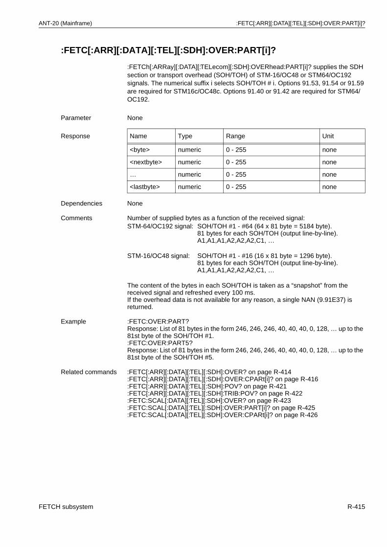
ANT-20 (Mainframe) :FETC[:ARR][:DATA][:TEL][:SDH]:OVER:PART[i]?
:FETC[:ARR][:DATA][:TEL][:SDH]:OVER:PART[i]?
:FETCh[:ARRay][:DATA][:TELecom][:SDH]:OVERhead:PART[i]? supplies the SDH section or transport overhead (SOH/TOH) of STM-16/OC48 or STM64/OC192 signals. The numerical suffix i selects SOH/TOH # i. Options 91.53, 91.54 or 91.59 are required for STM16c/OC48c. Options 91.40 or 91.42 are required for STM64/OC192.
Parameter None
Response Name Type Range Unit
<byte> numeric 0 - 255 none
<nextbyte> numeric 0 - 255 none
… numeric 0 - 255 none
<lastbyte> numeric 0 - 255 none
Dependencies None
Comments Number of supplied bytes as a function of the received signal:STM-64/OC192 signal: SOH/TOH #1 - #64 (64 x 81 byte = 5184 byte).
81 bytes for each SOH/TOH (output line-by-line).A1,A1,A1,A2,A2,A2,C1, …
STM-16/OC48 signal: SOH/TOH #1 - #16 (16 x 81 byte = 1296 byte).81 bytes for each SOH/TOH (output line-by-line).A1,A1,A1,A2,A2,A2,C1, …
The content of the bytes in each SOH/TOH is taken as a “snapshot” from the received signal and refreshed every 100 ms.If the overhead data is not available for any reason, a single NAN (9.91E37) is returned.
Example :FETC:OVER:PART?Response: List of 81 bytes in the form 246, 246, 246, 40, 40, 40, 0, 128, … up to the 81st byte of the SOH/TOH #1.:FETC:OVER:PART5?Response: List of 81 bytes in the form 246, 246, 246, 40, 40, 40, 0, 128, … up to the 81st byte of the SOH/TOH #5.
Related commands :FETC[:ARR][:DATA][:TEL][:SDH]:OVER? on page R-414:FETC[:ARR][:DATA][:TEL][:SDH]:OVER:CPARt[i]? on page R-416:FETC[:ARR][:DATA][:TEL][:SDH]:POV? on page R-421:FETC[:ARR][:DATA][:TEL][:SDH]:TRIB:POV? on page R-422:FETC:SCAL[:DATA][:TEL][:SDH]:OVER? on page R-423:FETC:SCAL[:DATA][:TEL][:SDH]:OVER:PART[i]? on page R-425:FETC:SCAL[:DATA][:TEL][:SDH]:OVER:CPARt[i]? on page R-426
FETCH subsystem R-415
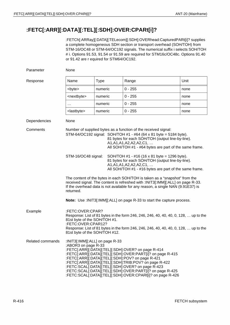
:FETC[:ARR][:DATA][:TEL][:SDH]:OVER:CPARt[i]? ANT-20 (Mainframe)
:FETC[:ARR][:DATA][:TEL][:SDH]:OVER:CPARt[i]?
:FETCh[:ARRay][:DATA][:TELecom][:SDH]:OVERhead:CapturedPARt[i]? supplies a complete homogeneous SDH section or transport overhead (SOH/TOH) from STM-16/OC48 or STM-64/OC192 signals. The numerical suffix i selects SOH/TOH # i. Options 91.53, 91.54 or 91.59 are required for STM16c/OC48c. Options 91.40 or 91.42 are r equired for STM64/OC192.
Note: Use :INIT3[:IMM][:ALL] on page R-33 to start the capture process.
Parameter None
Response Name Type Range Unit
<byte> numeric 0 - 255 none
<nextbyte> numeric 0 - 255 none
… numeric 0 - 255 none
<lastbyte> numeric 0 - 255 none
Dependencies None
Comments Number of supplied bytes as a function of the received signal:STM-64/OC192 signal: SOH/TOH #1 - #64 (64 x 81 byte = 5184 byte).
81 bytes for each SOH/TOH (output line-by-line).A1,A1,A1,A2,A2,A2,C1, …All SOH/TOH #1 - #64 bytes are part of the same frame.
STM-16/OC48 signal: SOH/TOH #1 - #16 (16 x 81 byte = 1296 byte).81 bytes for each SOH/TOH (output line-by-line).A1,A1,A1,A2,A2,A2,C1, …All SOH/TOH #1 - #16 bytes are part of the same frame.
The content of the bytes in each SOH/TOH is taken as a “snapshot” from the received signal. The content is refreshed with :INIT3[:IMM][:ALL] on page R-33.If the overhead data is not available for any reason, a single NAN (9.91E37) is returned.
Example :FETC:OVER:CPAR?Response: List of 81 bytes in the form 246, 246, 246, 40, 40, 40, 0, 128, … up to the 81st byte of the SOH/TOH #1.:FETC:OVER:CPAR12?Response: List of 81 bytes in the form 246, 246, 246, 40, 40, 40, 0, 128, … up to the 81st byte of the SOH/TOH #12.
Related commands :INIT3[:IMM][:ALL] on page R-33:ABOR3 on page R-33:FETC[:ARR][:DATA][:TEL][:SDH]:OVER? on page R-414:FETC[:ARR][:DATA][:TEL][:SDH]:OVER:PART[i]? on page R-415:FETC[:ARR][:DATA][:TEL][:SDH]:POV? on page R-421:FETC[:ARR][:DATA][:TEL][:SDH]:TRIB:POV? on page R-422:FETC:SCAL[:DATA][:TEL][:SDH]:OVER? on page R-423:FETC:SCAL[:DATA][:TEL][:SDH]:OVER:PART[i]? on page R-425:FETC:SCAL[:DATA][:TEL][:SDH]:OVER:CPARt[i]? on page R-426
R-416 FETCH subsystem
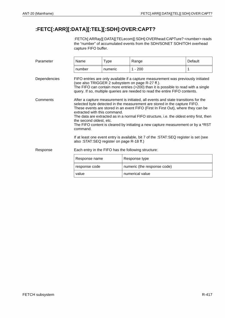
ANT-20 (Mainframe) :FETC[:ARR][:DATA][:TEL][:SDH]:OVER:CAPT?
:FETC[:ARR][:DATA][:TEL][:SDH]:OVER:CAPT?
:FETCh[:ARRay][:DATA][:TELecom][:SDH]:OVERhead:CAPTure? <number> reads the “number” of accumulated events from the SDH/SONET SOH/TOH overhead capture FIFO buffer.
Parameter Name Type Range Default
number numeric 1 - 200 1
Dependencies FIFO entries are only available if a capture measurement was previously initiated (see also TRIGGER 2 subsystem on page R-27 ff.).The FIFO can contain more entries (>200) than it is possible to read with a single query. If so, multiple queries are needed to read the entire FIFO contents.
Comments After a capture measurement is initiated, all events and state transitions for the selected byte detected in the measurement are stored in the capture FIFO.These events are stored in an event FIFO (First In First Out), where they can be extracted with this command.The data are extracted as in a normal FIFO structure, i.e. the oldest entry first, then the second oldest, etc.The FIFO content is cleared by initiating a new capture measurement or by a *RST command.
If at least one event entry is available, bit 7 of the :STAT:SEQ register is set (see also :STAT:SEQ register on page R-18 ff.)
Response Each entry in the FIFO has the following structure:
Response name Response type
response code numeric (the response code)
value numerical value
FETCH subsystem R-417
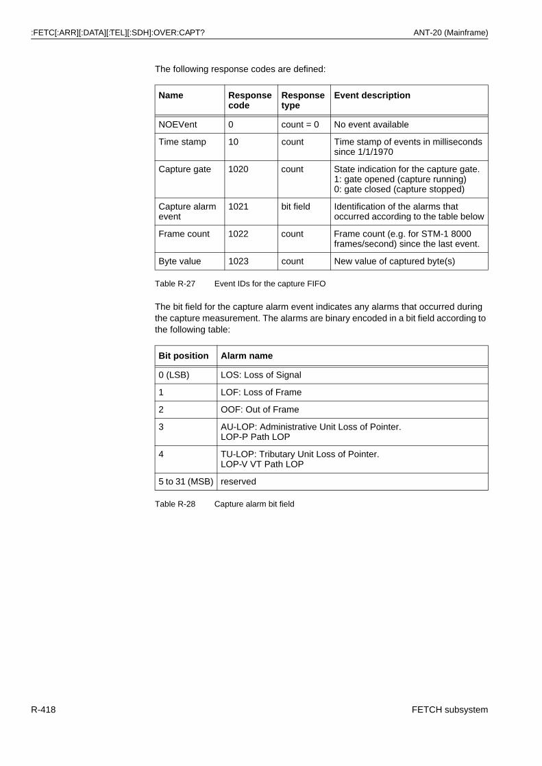
:FETC[:ARR][:DATA][:TEL][:SDH]:OVER:CAPT? ANT-20 (Mainframe)
The following response codes are defined:
The bit field for the capture alarm event indicates any alarms that occurred during the capture measurement. The alarms are binary encoded in a bit field according to the following table:
Name Response code
Response type
Event description
NOEVent 0 count = 0 No event available
Time stamp 10 count Time stamp of events in milliseconds since 1/1/1970
Capture gate 1020 count State indication for the capture gate.1: gate opened (capture running)0: gate closed (capture stopped)
Capture alarm event
1021 bit field Identification of the alarms that occurred according to the table below
Frame count 1022 count Frame count (e.g. for STM-1 8000 frames/second) since the last event.
Byte value 1023 count New value of captured byte(s)
Table R-27 Event IDs for the capture FIFO
Bit position Alarm name
0 (LSB) LOS: Loss of Signal
1 LOF: Loss of Frame
2 OOF: Out of Frame
3 AU-LOP: Administrative Unit Loss of Pointer.LOP-P Path LOP
4 TU-LOP: Tributary Unit Loss of Pointer.LOP-V VT Path LOP
5 to 31 (MSB) reserved
Table R-28 Capture alarm bit field
R-418 FETCH subsystem
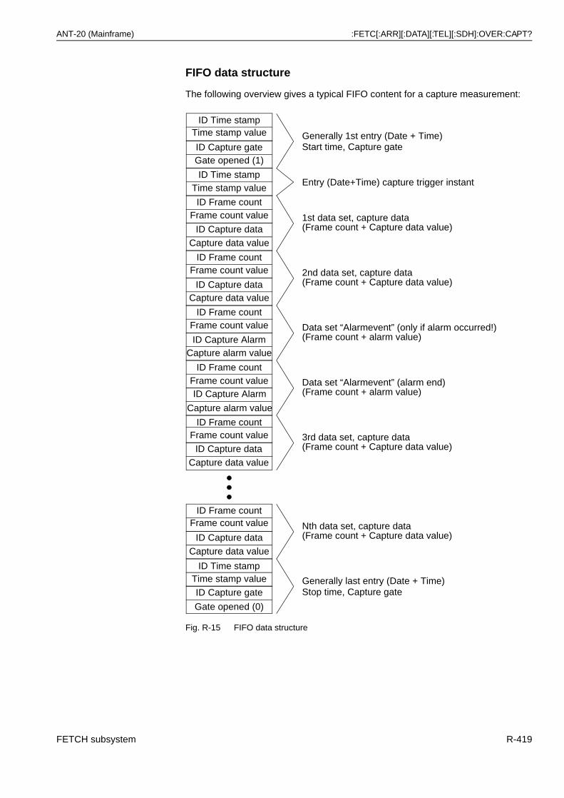
ANT-20 (Mainframe) :FETC[:ARR][:DATA][:TEL][:SDH]:OVER:CAPT?
FIFO data structure
The following overview gives a typical FIFO content for a capture measurement:
Fig. R-15 FIFO data structure
ID Time stampTime stamp value
ID Capture data
Capture data value
ID Capture AlarmCapture alarm value
ID Frame countFrame count value
ID Capture dataCapture data value
ID Frame countFrame count value
ID Frame countFrame count value
ID Capture Alarm
Capture alarm value
ID Frame countFrame count value
ID Capture data
Capture data value
ID Frame countFrame count value
ID Capture data
Capture data value
ID Frame countFrame count value
Generally 1st entry (Date + Time)
1st data set, capture data(Frame count + Capture data value)
2nd data set, capture data(Frame count + Capture data value)
Data set “Alarmevent” (only if alarm occurred!)(Frame count + alarm value)
Data set “Alarmevent” (alarm end)(Frame count + alarm value)
3rd data set, capture data(Frame count + Capture data value)
Nth data set, capture data(Frame count + Capture data value)
ID Time stampTime stamp value
ID Capture gateGate opened (1)
Entry (Date+Time) capture trigger instant
ID Time stampTime stamp value Generally last entry (Date + Time)ID Capture gate
Gate opened (0)
Stop time, Capture gate
Start time, Capture gate
FETCH subsystem R-419
:FETC[:ARR][:DATA][:TEL][:SDH]:OVER:CAPT:NUMB? ANT-20 (Mainframe)
:FETC[:ARR][:DATA][:TEL][:SDH]:OVER:CAPT:NUMB?
:FETCh[:ARRay][:DATA][:TELecom][:SDH]:OVERhead:CAPTure:NUMBer? supplies the number of events available in the SDH/SONET SOH/TOH overhead capture FIFO buffer.
Example :FETC:OVER:CAPT? 20 supplies up to 20 events out of the capture FIFO.
Response:10,0.5268700E7,1020,1,10,0.5272700E7,1022,0,1023,255,1022,8000,1023,254,10,0.5272700E7,1020,0,0,0
meaning:10 ID Time stamp (measurement start time)0.5268700E7 ms since 1970/1/11020 ID Capture gate1 gate opened (trigger reached)10 ID Time stamp (trigger time)0.5272700E7 ms since 1970/1/11022 ID Frame count0 frame count since trigger time (0 frames)1023 ID Byte value255 1 st. captured byte value (255 = FF HEX)1022 ID Frame count8000 frame count since trigger time (8000 frames)1023 ID Byte value254 2 nd. captured byte value (254 = FE HEX)10 ID Time stamp (measurement stop time)0.5282700E7 ms since 1970/1/11020 ID Capture gate0 gate closed (measurement aborted)0 ID NOEVent (no more data available)0 No data flag
Related commands :FETC[:ARR][:DATA][:TEL][:SDH]:OVER:CAPT:NUMB? on page R-420TRIGGER 2 subsystem on page R-27 ff.
Parameter None
Example :FETC:OVER:CAPT:NUMB?Response: 88 for 88 available events.
Related commands :FETC[:ARR][:DATA][:TEL][:SDH]:OVER:CAPT:NUMB? on page R-420TRIGGER 2 subsystem on page R-27 ff.
R-420 FETCH subsystem
ANT-20 (Mainframe) :FETC[:ARR][:DATA][:TEL][:SDH]:POV?
:FETC[:ARR][:DATA][:TEL][:SDH]:POV?
:FETCh[:ARRay][:DATA][:TELecom][:SDH]:POVerhead? supplies the VC-4/VC-3 high path overhead (POH) (STS1SPE POH).
Parameter None
Response Name Type Range Unit
<J1> numeric 0 - 255 none
<B3> numeric 0 - 255 none
<C2> numeric 0 - 255 none
<G1> numeric 0 - 255 none
<F2> numeric 0 - 255 none
<H4> numeric 0 - 255 none
<F3> numeric 0 - 255 none
<K3> numeric 0 - 255 none
<N1> numeric 0 - 255 none
Dependencies The POH is always taken from the current measurement channel!
Comments The complete high path POH is output.The VC-4 POH is supplied for SDH mapping with VC-4 in the high order path.The VC-3 POH is supplied for SDH mapping with VC-3 in the high order path.The STS1SPE POH is supplied for SONET signals with STS1 mapping.The STS3C POH is supplied for SONET signals with STS3C mapping.With STM4C/OC12C virtual concatenation, there are 4 POHs that belong together. In this case, all 4 POHs (4 x 9 = 36 bytes) taken from the same SDH/SONET frame are supplied, i.e. the 9 bytes from the 1st. POH first, followed by the 2nd. 9 bytes and so on.
The content of the bytes in the active measurement channel is taken as a “snapshot” from the received signal and refreshed every 100 ms.If the overhead data is not available for any reason, a single NAN (9,91E37) is returned.
Example :FETC:POV?Response: 00,15,254,0,0,255,0,0,0
For virtual concatenation:FETC:POV?Response:0,15,2,0,0,255,0,0,0,0,7,2,0,0,255,0,0,0,0,127,2,0,0,255,0,0,0,0,235,2,0,0,255,0,0,0
POH #1POH #2POH #3POH #4
Related commands :FETC[:ARR][:DATA][:TEL][:SDH]:OVER? on page R-414:FETC[:ARR][:DATA][:TEL][:SDH]:TRIB:POV? on page R-422
FETCH subsystem R-421
:FETC[:ARR][:DATA][:TEL][:SDH]:TRIB:POV? ANT-20 (Mainframe)
:FETC[:ARR][:DATA][:TEL][:SDH]:TRIB:POV?
:FETCh[:ARRay][:DATA][:TELecom][:SDH]:TRIButary:POVerhead? supplies the tributary low order path overhead (POH). In VC-12/11 and VT1.5/VT2 mapping, these are the V5/J2/Z6/K4 bytes.
Parameter None
Response For the VC-12/11/2 mapping:
Name Type Range Unit
<V5> numeric 0 - 255 none
<J2> numeric 0 - 255 none
<N2> numeric 0 - 255 none
<K4> numeric 0 - 255 none
Response For VC-3 mapping:
Name Type Range Unit
<J1> numeric 0 - 255 none
<B3> numeric 0 - 255 none
<C2> numeric 0 - 255 none
<G1> numeric 0 - 255 none
<F2> numeric 0 - 255 none
<H4> numeric 0 - 255 none
<F3> numeric 0 - 255 none
<K3> numeric 0 - 255 none
<N1> numeric 0 - 255 none
Dependencies The POH is always taken from the current measurement channel!
Comments The content of the bytes in the active measurement channel is taken as a “snapshot” from the received signal and refreshed every 100 ms.If the overhead data is not available for any reason, a single NAN (9,91E37) is returned.
Example :FETC:TRIB:POV?Response: 2,0,0,0
Related commands :FETC[:ARR][:DATA][:TEL][:SDH]:OVER? on page R-414:FETC[:ARR][:DATA][:TEL][:SDH]:POV? on page R-421
R-422 FETCH subsystem
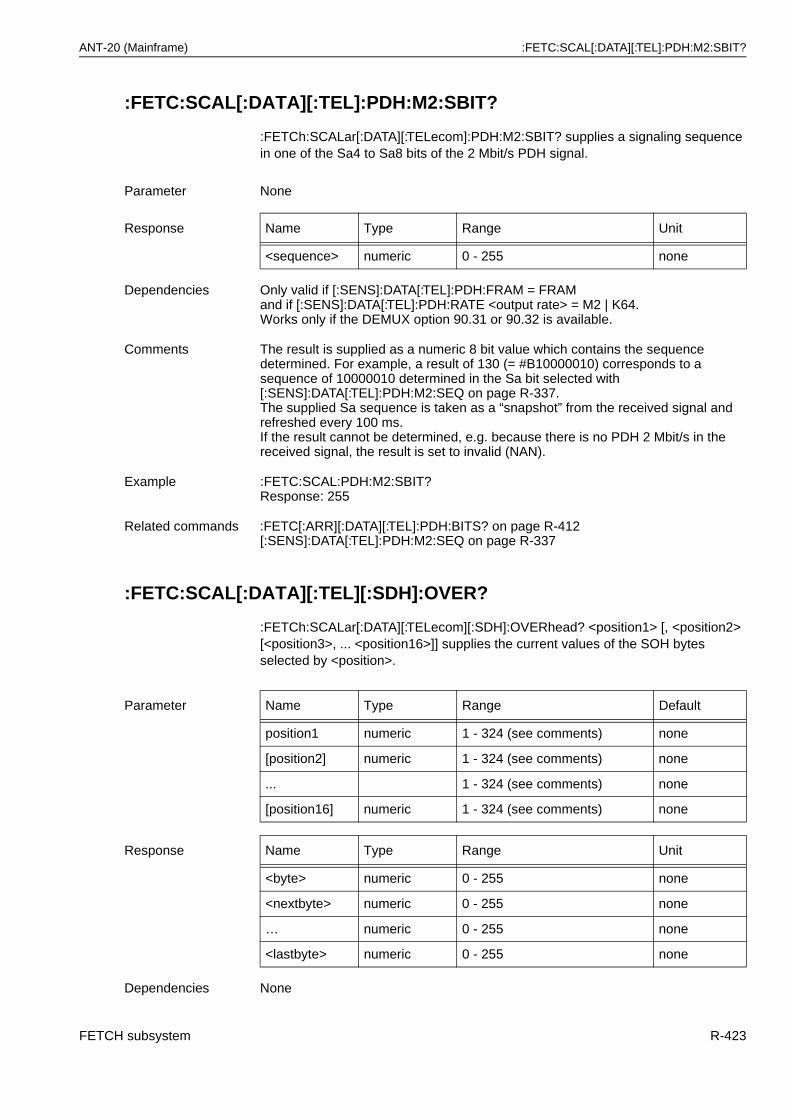
ANT-20 (Mainframe) :FETC:SCAL[:DATA][:TEL]:PDH:M2:SBIT?
:FETC:SCAL[:DATA][:TEL]:PDH:M2:SBIT?
:FETCh:SCALar[:DATA][:TELecom]:PDH:M2:SBIT? supplies a signaling sequence in one of the Sa4 to Sa8 bits of the 2 Mbit/s PDH signal.
:FETC:SCAL[:DATA][:TEL][:SDH]:OVER?
:FETCh:SCALar[:DATA][:TELecom][:SDH]:OVERhead? <position1> [, <position2> [<position3>, ... <position16>]] supplies the current values of the SOH bytes selected by <position>.
Parameter None
Response Name Type Range Unit
<sequence> numeric 0 - 255 none
Dependencies Only valid if [:SENS]:DATA[:TEL]:PDH:FRAM = FRAMand if [:SENS]:DATA[:TEL]:PDH:RATE <output rate> = M2 | K64.Works only if the DEMUX option 90.31 or 90.32 is available.
Comments The result is supplied as a numeric 8 bit value which contains the sequence determined. For example, a result of 130 (= #B10000010) corresponds to a sequence of 10000010 determined in the Sa bit selected with[:SENS]:DATA[:TEL]:PDH:M2:SEQ on page R-337.The supplied Sa sequence is taken as a “snapshot” from the received signal and refreshed every 100 ms.If the result cannot be determined, e.g. because there is no PDH 2 Mbit/s in the received signal, the result is set to invalid (NAN).
Example :FETC:SCAL:PDH:M2:SBIT?Response: 255
Related commands :FETC[:ARR][:DATA][:TEL]:PDH:BITS? on page R-412[:SENS]:DATA[:TEL]:PDH:M2:SEQ on page R-337
Parameter Name Type Range Default
position1 numeric 1 - 324 (see comments) none
[position2] numeric 1 - 324 (see comments) none
... 1 - 324 (see comments) none
[position16] numeric 1 - 324 (see comments) none
Response Name Type Range Unit
<byte> numeric 0 - 255 none
<nextbyte> numeric 0 - 255 none
… numeric 0 - 255 none
<lastbyte> numeric 0 - 255 none
Dependencies None
FETCH subsystem R-423
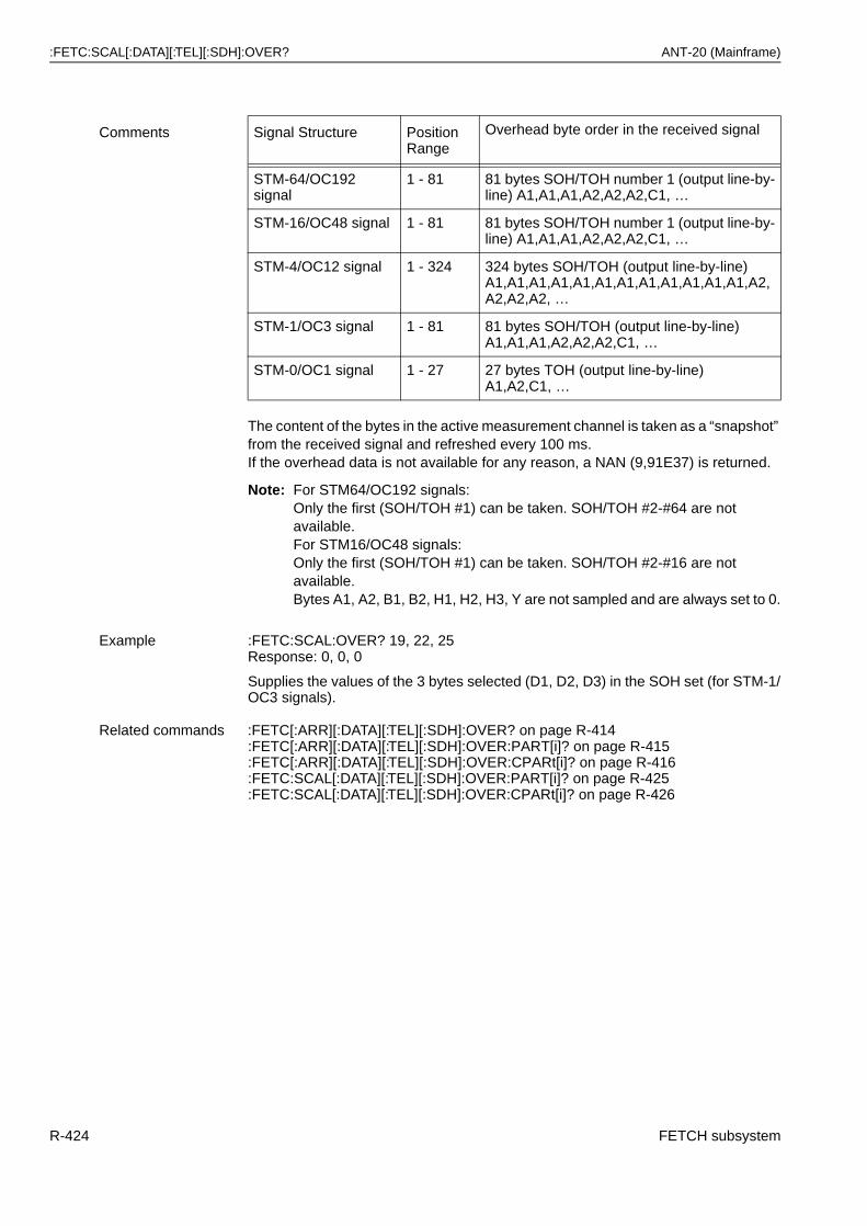
:FETC:SCAL[:DATA][:TEL][:SDH]:OVER? ANT-20 (Mainframe)
The content of the bytes in the active measurement channel is taken as a “snapshot” from the received signal and refreshed every 100 ms.If the overhead data is not available for any reason, a NAN (9,91E37) is returned.
Note: For STM64/OC192 signals:Only the first (SOH/TOH #1) can be taken. SOH/TOH #2-#64 are not available.For STM16/OC48 signals:Only the first (SOH/TOH #1) can be taken. SOH/TOH #2-#16 are not available.Bytes A1, A2, B1, B2, H1, H2, H3, Y are not sampled and are always set to 0.
Comments Signal Structure Position Range
Overhead byte order in the received signal
STM-64/OC192 signal
1 - 81 81 bytes SOH/TOH number 1 (output line-by-line) A1,A1,A1,A2,A2,A2,C1, …
STM-16/OC48 signal 1 - 81 81 bytes SOH/TOH number 1 (output line-by-line) A1,A1,A1,A2,A2,A2,C1, …
STM-4/OC12 signal 1 - 324 324 bytes SOH/TOH (output line-by-line)A1,A1,A1,A1,A1,A1,A1,A1,A1,A1,A1,A1,A2,A2,A2,A2, …
STM-1/OC3 signal 1 - 81 81 bytes SOH/TOH (output line-by-line)A1,A1,A1,A2,A2,A2,C1, …
STM-0/OC1 signal 1 - 27 27 bytes TOH (output line-by-line)A1,A2,C1, …
Example :FETC:SCAL:OVER? 19, 22, 25Response: 0, 0, 0
Supplies the values of the 3 bytes selected (D1, D2, D3) in the SOH set (for STM-1/OC3 signals).
Related commands :FETC[:ARR][:DATA][:TEL][:SDH]:OVER? on page R-414:FETC[:ARR][:DATA][:TEL][:SDH]:OVER:PART[i]? on page R-415:FETC[:ARR][:DATA][:TEL][:SDH]:OVER:CPARt[i]? on page R-416:FETC:SCAL[:DATA][:TEL][:SDH]:OVER:PART[i]? on page R-425:FETC:SCAL[:DATA][:TEL][:SDH]:OVER:CPARt[i]? on page R-426
R-424 FETCH subsystem
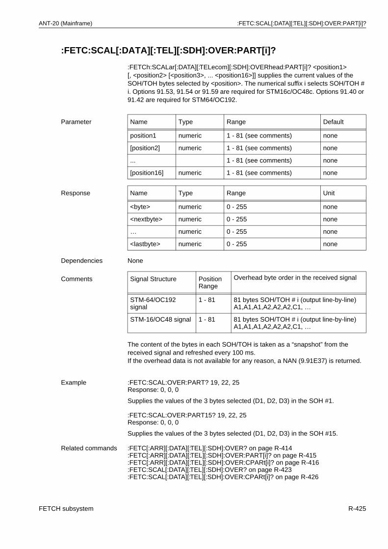
ANT-20 (Mainframe) :FETC:SCAL[:DATA][:TEL][:SDH]:OVER:PART[i]?
:FETC:SCAL[:DATA][:TEL][:SDH]:OVER:PART[i]?
:FETCh:SCALar[:DATA][:TELecom][:SDH]:OVERhead:PART[i]? <position1> [, <position2> [<position3>, ... <position16>]] supplies the current values of the SOH/TOH bytes selected by <position>. The numerical suffix i selects SOH/TOH # i. Options 91.53, 91.54 or 91.59 are required for STM16c/OC48c. Options 91.40 or 91.42 are required for STM64/OC192.
The content of the bytes in each SOH/TOH is taken as a “snapshot” from the received signal and refreshed every 100 ms.If the overhead data is not available for any reason, a NAN (9.91E37) is returned.
Parameter Name Type Range Default
position1 numeric 1 - 81 (see comments) none
[position2] numeric 1 - 81 (see comments) none
... 1 - 81 (see comments) none
[position16] numeric 1 - 81 (see comments) none
Response Name Type Range Unit
<byte> numeric 0 - 255 none
<nextbyte> numeric 0 - 255 none
… numeric 0 - 255 none
<lastbyte> numeric 0 - 255 none
Dependencies None
Comments Signal Structure Position Range
Overhead byte order in the received signal
STM-64/OC192 signal
1 - 81 81 bytes SOH/TOH # i (output line-by-line) A1,A1,A1,A2,A2,A2,C1, …
STM-16/OC48 signal 1 - 81 81 bytes SOH/TOH # i (output line-by-line) A1,A1,A1,A2,A2,A2,C1, …
Example :FETC:SCAL:OVER:PART? 19, 22, 25Response: 0, 0, 0
Supplies the values of the 3 bytes selected (D1, D2, D3) in the SOH #1.
:FETC:SCAL:OVER:PART15? 19, 22, 25Response: 0, 0, 0
Supplies the values of the 3 bytes selected (D1, D2, D3) in the SOH #15.
Related commands :FETC[:ARR][:DATA][:TEL][:SDH]:OVER? on page R-414:FETC[:ARR][:DATA][:TEL][:SDH]:OVER:PART[i]? on page R-415:FETC[:ARR][:DATA][:TEL][:SDH]:OVER:CPARt[i]? on page R-416:FETC:SCAL[:DATA][:TEL][:SDH]:OVER? on page R-423:FETC:SCAL[:DATA][:TEL][:SDH]:OVER:CPARt[i]? on page R-426
FETCH subsystem R-425
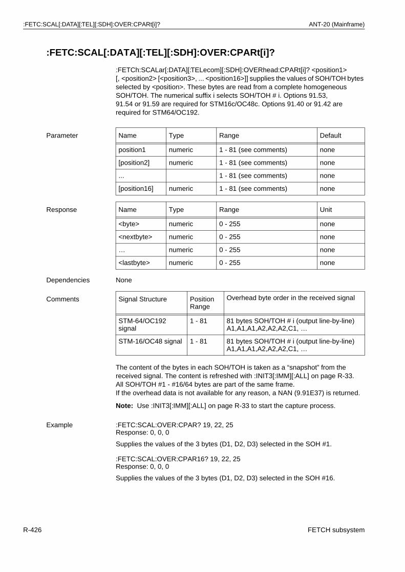
:FETC:SCAL[:DATA][:TEL][:SDH]:OVER:CPARt[i]? ANT-20 (Mainframe)
:FETC:SCAL[:DATA][:TEL][:SDH]:OVER:CPARt[i]?
:FETCh:SCALar[:DATA][:TELecom][:SDH]:OVERhead:CPARt[i]? <position1> [, <position2> [<position3>, ... <position16>]] supplies the values of SOH/TOH bytes selected by <position>. These bytes are read from a complete homogeneous SOH/TOH. The numerical suffix i selects SOH/TOH # i. Options 91.53, 91.54 or 91.59 are required for STM16c/OC48c. Options 91.40 or 91.42 are required for STM64/OC192.
The content of the bytes in each SOH/TOH is taken as a “snapshot” from the received signal. The content is refreshed with :INIT3[:IMM][:ALL] on page R-33.All SOH/TOH #1 - #16/64 bytes are part of the same frame.If the overhead data is not available for any reason, a NAN (9.91E37) is returned.
Note: Use :INIT3[:IMM][:ALL] on page R-33 to start the capture process.
Parameter Name Type Range Default
position1 numeric 1 - 81 (see comments) none
[position2] numeric 1 - 81 (see comments) none
... 1 - 81 (see comments) none
[position16] numeric 1 - 81 (see comments) none
Response Name Type Range Unit
<byte> numeric 0 - 255 none
<nextbyte> numeric 0 - 255 none
… numeric 0 - 255 none
<lastbyte> numeric 0 - 255 none
Dependencies None
Comments Signal Structure Position Range
Overhead byte order in the received signal
STM-64/OC192 signal
1 - 81 81 bytes SOH/TOH # i (output line-by-line) A1,A1,A1,A2,A2,A2,C1, …
STM-16/OC48 signal 1 - 81 81 bytes SOH/TOH # i (output line-by-line) A1,A1,A1,A2,A2,A2,C1, …
Example :FETC:SCAL:OVER:CPAR? 19, 22, 25Response: 0, 0, 0
Supplies the values of the 3 bytes (D1, D2, D3) selected in the SOH #1.
:FETC:SCAL:OVER:CPAR16? 19, 22, 25Response: 0, 0, 0
Supplies the values of the 3 bytes (D1, D2, D3) selected in the SOH #16.
R-426 FETCH subsystem
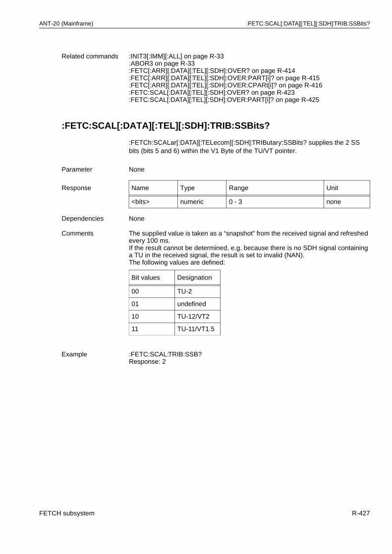
ANT-20 (Mainframe) :FETC:SCAL[:DATA][:TEL][:SDH]:TRIB:SSBits?
:FETC:SCAL[:DATA][:TEL][:SDH]:TRIB:SSBits?
:FETCh:SCALar[:DATA][:TELecom][:SDH]:TRIButary:SSBits? supplies the 2 SS bits (bits 5 and 6) within the V1 Byte of the TU/VT pointer.
Related commands :INIT3[:IMM][:ALL] on page R-33:ABOR3 on page R-33:FETC[:ARR][:DATA][:TEL][:SDH]:OVER? on page R-414:FETC[:ARR][:DATA][:TEL][:SDH]:OVER:PART[i]? on page R-415:FETC[:ARR][:DATA][:TEL][:SDH]:OVER:CPARt[i]? on page R-416:FETC:SCAL[:DATA][:TEL][:SDH]:OVER? on page R-423:FETC:SCAL[:DATA][:TEL][:SDH]:OVER:PART[i]? on page R-425
Parameter None
Response Name Type Range Unit
<bits> numeric 0 - 3 none
Dependencies None
Comments The supplied value is taken as a “snapshot” from the received signal and refreshed every 100 ms.If the result cannot be determined, e.g. because there is no SDH signal containing a TU in the received signal, the result is set to invalid (NAN).The following values are defined:
Bit values Designation
00 TU-2
01 undefined
10 TU-12/VT2
11 TU-11/VT1.5
Example :FETC:SCAL:TRIB:SSB?Response: 2
FETCH subsystem R-427
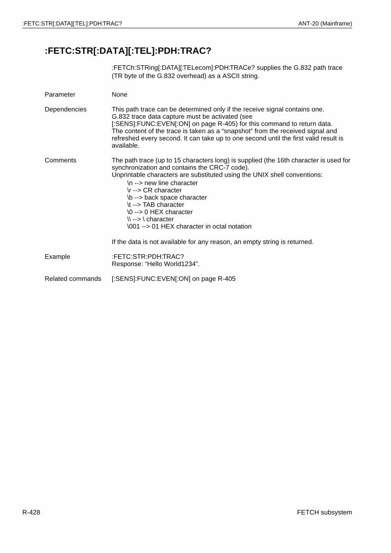
:FETC:STR[:DATA][:TEL]:PDH:TRAC? ANT-20 (Mainframe)
:FETC:STR[:DATA][:TEL]:PDH:TRAC?
:FETCh:STRing[:DATA][:TELecom]:PDH:TRACe? supplies the G.832 path trace (TR byte of the G.832 overhead) as a ASCII string.
Parameter None
Dependencies This path trace can be determined only if the receive signal contains one.G.832 trace data capture must be activated (see [:SENS]:FUNC:EVEN[:ON] on page R-405) for this command to return data.The content of the trace is taken as a “snapshot” from the received signal and refreshed every second. It can take up to one second until the first valid result is available.
Comments The path trace (up to 15 characters long) is supplied (the 16th character is used for synchronization and contains the CRC-7 code). Unprintable characters are substituted using the UNIX shell conventions:
\n --> new line character\r --> CR character\b --> back space character\t --> TAB character\0 --> 0 HEX character\\ --> \ character\001 --> 01 HEX character in octal notation
If the data is not available for any reason, an empty string is returned.
Example :FETC:STR:PDH:TRAC?Response: “Hello World1234”.
Related commands [:SENS]:FUNC:EVEN[:ON] on page R-405
R-428 FETCH subsystem
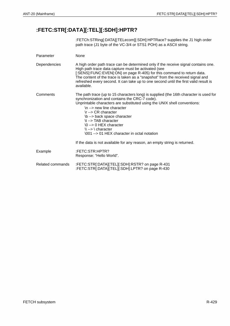
ANT-20 (Mainframe) :FETC:STR[:DATA][:TEL][:SDH]:HPTR?
:FETC:STR[:DATA][:TEL][:SDH]:HPTR?
:FETCh:STRing[:DATA][:TELecom][:SDH]:HPTRace? supplies the J1 high order path trace (J1 byte of the VC-3/4 or STS1 POH) as a ASCII string.
Parameter None
Dependencies A high order path trace can be determined only if the receive signal contains one.High path trace data capture must be activated (see [:SENS]:FUNC:EVEN[:ON] on page R-405) for this command to return data.The content of the trace is taken as a “snapshot” from the received signal and refreshed every second. It can take up to one second until the first valid result is available.
Comments The path trace (up to 15 characters long) is supplied (the 16th character is used for synchronization and contains the CRC-7 code). Unprintable characters are substituted using the UNIX shell conventions:
\n --> new line character\r --> CR character\b --> back space character\t --> TAB character\0 --> 0 HEX character\\ --> \ character\001 --> 01 HEX character in octal notation
If the data is not available for any reason, an empty string is returned.
Example :FETC:STR:HPTR?Response: “Hello World”.
Related commands :FETC:STR[:DATA][:TEL][:SDH]:RSTR? on page R-431:FETC:STR[:DATA][:TEL][:SDH]:LPTR? on page R-430
FETCH subsystem R-429
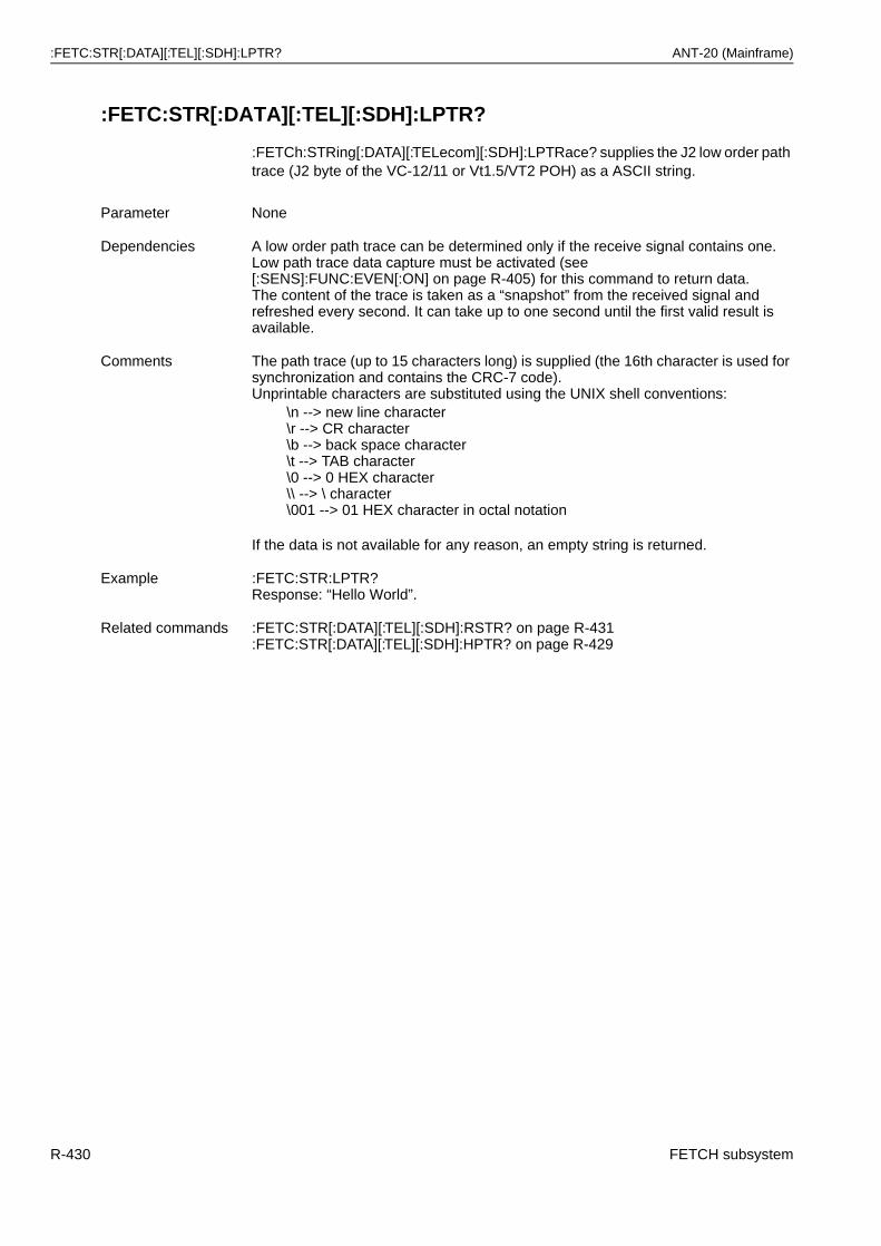
:FETC:STR[:DATA][:TEL][:SDH]:LPTR? ANT-20 (Mainframe)
:FETC:STR[:DATA][:TEL][:SDH]:LPTR?
:FETCh:STRing[:DATA][:TELecom][:SDH]:LPTRace? supplies the J2 low order path trace (J2 byte of the VC-12/11 or Vt1.5/VT2 POH) as a ASCII string.
Parameter None
Dependencies A low order path trace can be determined only if the receive signal contains one.Low path trace data capture must be activated (see [:SENS]:FUNC:EVEN[:ON] on page R-405) for this command to return data.The content of the trace is taken as a “snapshot” from the received signal and refreshed every second. It can take up to one second until the first valid result is available.
Comments The path trace (up to 15 characters long) is supplied (the 16th character is used for synchronization and contains the CRC-7 code). Unprintable characters are substituted using the UNIX shell conventions:
\n --> new line character\r --> CR character\b --> back space character\t --> TAB character\0 --> 0 HEX character\\ --> \ character\001 --> 01 HEX character in octal notation
If the data is not available for any reason, an empty string is returned.
Example :FETC:STR:LPTR?Response: “Hello World”.
Related commands :FETC:STR[:DATA][:TEL][:SDH]:RSTR? on page R-431:FETC:STR[:DATA][:TEL][:SDH]:HPTR? on page R-429
R-430 FETCH subsystem
ANT-20 (Mainframe) :FETC:STR[:DATA][:TEL][:SDH]:RSTR?
:FETC:STR[:DATA][:TEL][:SDH]:RSTR?
:FETCh:STRing[:DATA][:TELecom][:SDH]:RSTRace? supplies the J0 regenerator section path trace (C1 byte of the SOH) as a ASCII string.
Parameter None
Dependencies A regenerator section path trace can be determined only if the receive signal contains one.Regenerator section trace data capture must be activated (see [:SENS]:FUNC:EVEN[:ON] on page R-405) for this command to return data.The content of the trace is taken as a “snapshot” from the received signal and refreshed every second. It can take up to one second until the first valid result is available.
Comments The path trace (up to 15 characters long) is supplied (the 16th character is used for synchronization and contains the CRC-7 code). Unprintable characters are substituted using the UNIX shell conventions:
\n --> new line character\r --> CR character\b --> back space character\t --> TAB character\0 --> 0 HEX character\\ --> \ character\001 --> 01 HEX character in octal notation
If the data is not available for any reason, an empty string is returned.
Example :FETC:STR:RSTR?Response: “Hello World”.
Related commands :FETC:STR[:DATA][:TEL][:SDH]:HPTR? on page R-429:FETC:STR[:DATA][:TEL][:SDH]:LPTR? on page R-430
FETCH subsystem R-431
:FETC:STR[:DATA][:TEL][:SDH]:TCMonitoring:TRACe? ANT-20 (Mainframe)
:FETC:STR[:DATA][:TEL][:SDH]:TCMonitoring:TRACe?
:FETCh:STRing[:DATA][:TELecom][:SDH]:TCMonitoring:TRace? supplies the tandem connection monitoring N1/N2 trace identifier as an ASCII string.
Parameter None
Dependencies A tandem connection monitoring trace identifier can be determined only if the receive signal contains one.TCM trace identifier data capture must be activated (see [:SENS]:FUNC:EVEN[:ON] on page R-405) for this command to return data.The content of the trace is taken as a “snapshot” from the received signal and refreshed every second. It can take up to one second until the first valid result is available.
Comments The TCM trace (up to 15 characters long) is supplied (the 16th character is used for synchronization and contains the CRC-7 code). Unprintable characters are substituted using the UNIX shell conventions:
\n --> new line character\r --> CR character\b --> back space character\t --> TAB character\0 --> 0 HEX character\\ --> \ character\001 --> 01 HEX character in octal notation
If the data is not available for any reason, an empty string is returned.
Example :FETC:STR:TCM:TRAC?Response: “TCM-TRACE-IDENT”.
Related commands :FETC:STR[:DATA][:TEL][:SDH]:HPTR? on page R-429:FETC:STR[:DATA][:TEL][:SDH]:LPTR? on page R-430
R-432 FETCH subsystem
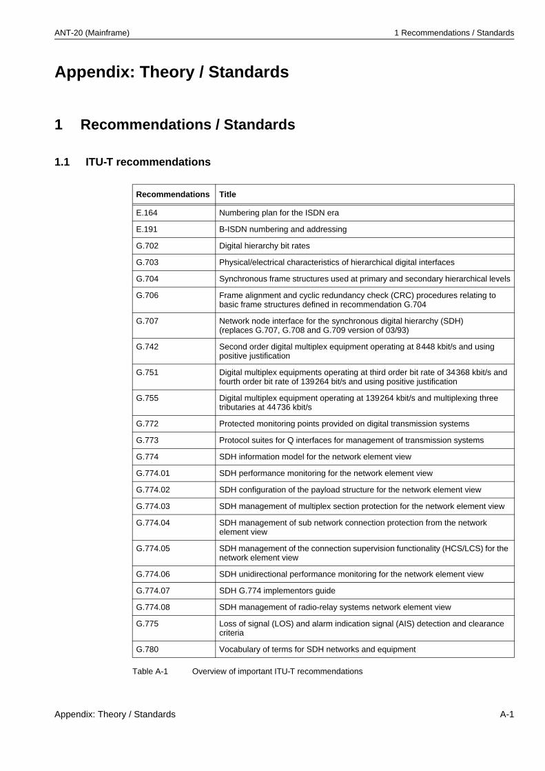
ANT-20 (Mainframe) 1 Recommendations / Standards
Appendix: Theory / Standards
1 Recommendations / Standards
1.1 ITU-T recommendations
Recommendations Title
E.164 Numbering plan for the ISDN era
E.191 B-ISDN numbering and addressing
G.702 Digital hierarchy bit rates
G.703 Physical/electrical characteristics of hierarchical digital interfaces
G.704 Synchronous frame structures used at primary and secondary hierarchical levels
G.706 Frame alignment and cyclic redundancy check (CRC) procedures relating to basic frame structures defined in recommendation G.704
G.707 Network node interface for the synchronous digital hierarchy (SDH)(replaces G.707, G.708 and G.709 version of 03/93)
G.742 Second order digital multiplex equipment operating at 8448 kbit/s and using positive justification
G.751 Digital multiplex equipments operating at third order bit rate of 34368 kbit/s and fourth order bit rate of 139264 bit/s and using positive justification
G.755 Digital multiplex equipment operating at 139264 kbit/s and multiplexing three tributaries at 44736 kbit/s
G.772 Protected monitoring points provided on digital transmission systems
G.773 Protocol suites for Q interfaces for management of transmission systems
G.774 SDH information model for the network element view
G.774.01 SDH performance monitoring for the network element view
G.774.02 SDH configuration of the payload structure for the network element view
G.774.03 SDH management of multiplex section protection for the network element view
G.774.04 SDH management of sub network connection protection from the network element view
G.774.05 SDH management of the connection supervision functionality (HCS/LCS) for the network element view
G.774.06 SDH unidirectional performance monitoring for the network element view
G.774.07 SDH G.774 implementors guide
G.774.08 SDH management of radio-relay systems network element view
G.775 Loss of signal (LOS) and alarm indication signal (AIS) detection and clearance criteria
G.780 Vocabulary of terms for SDH networks and equipment
Table A-1 Overview of important ITU-T recommendations
Appendix: Theory / Standards A-1
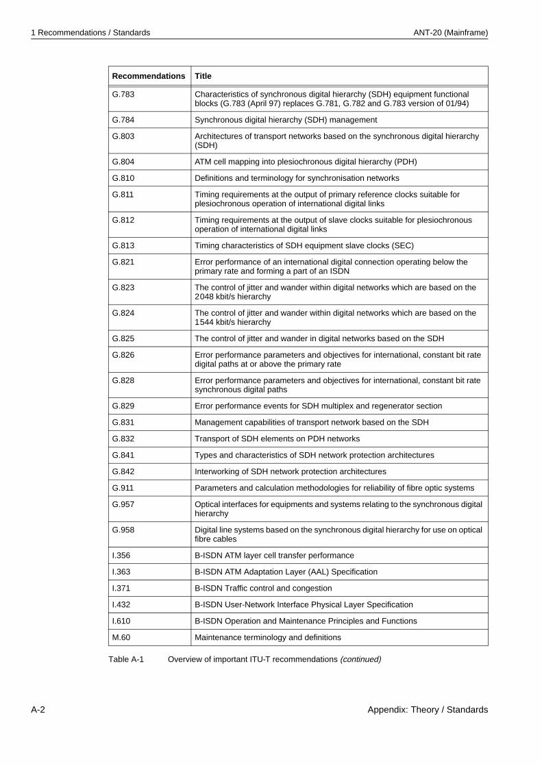
1 Recommendations / Standards ANT-20 (Mainframe)
G.783 Characteristics of synchronous digital hierarchy (SDH) equipment functional blocks (G.783 (April 97) replaces G.781, G.782 and G.783 version of 01/94)
G.784 Synchronous digital hierarchy (SDH) management
G.803 Architectures of transport networks based on the synchronous digital hierarchy (SDH)
G.804 ATM cell mapping into plesiochronous digital hierarchy (PDH)
G.810 Definitions and terminology for synchronisation networks
G.811 Timing requirements at the output of primary reference clocks suitable for plesiochronous operation of international digital links
G.812 Timing requirements at the output of slave clocks suitable for plesiochronous operation of international digital links
G.813 Timing characteristics of SDH equipment slave clocks (SEC)
G.821 Error performance of an international digital connection operating below the primary rate and forming a part of an ISDN
G.823 The control of jitter and wander within digital networks which are based on the 2048 kbit/s hierarchy
G.824 The control of jitter and wander within digital networks which are based on the 1544 kbit/s hierarchy
G.825 The control of jitter and wander in digital networks based on the SDH
G.826 Error performance parameters and objectives for international, constant bit rate digital paths at or above the primary rate
G.828 Error performance parameters and objectives for international, constant bit rate synchronous digital paths
G.829 Error performance events for SDH multiplex and regenerator section
G.831 Management capabilities of transport network based on the SDH
G.832 Transport of SDH elements on PDH networks
G.841 Types and characteristics of SDH network protection architectures
G.842 Interworking of SDH network protection architectures
G.911 Parameters and calculation methodologies for reliability of fibre optic systems
G.957 Optical interfaces for equipments and systems relating to the synchronous digital hierarchy
G.958 Digital line systems based on the synchronous digital hierarchy for use on optical fibre cables
I.356 B-ISDN ATM layer cell transfer performance
I.363 B-ISDN ATM Adaptation Layer (AAL) Specification
I.371 B-ISDN Traffic control and congestion
I.432 B-ISDN User-Network Interface Physical Layer Specification
I.610 B-ISDN Operation and Maintenance Principles and Functions
M.60 Maintenance terminology and definitions
Recommendations Title
Table A-1 Overview of important ITU-T recommendations (continued)
A-2 Appendix: Theory / Standards
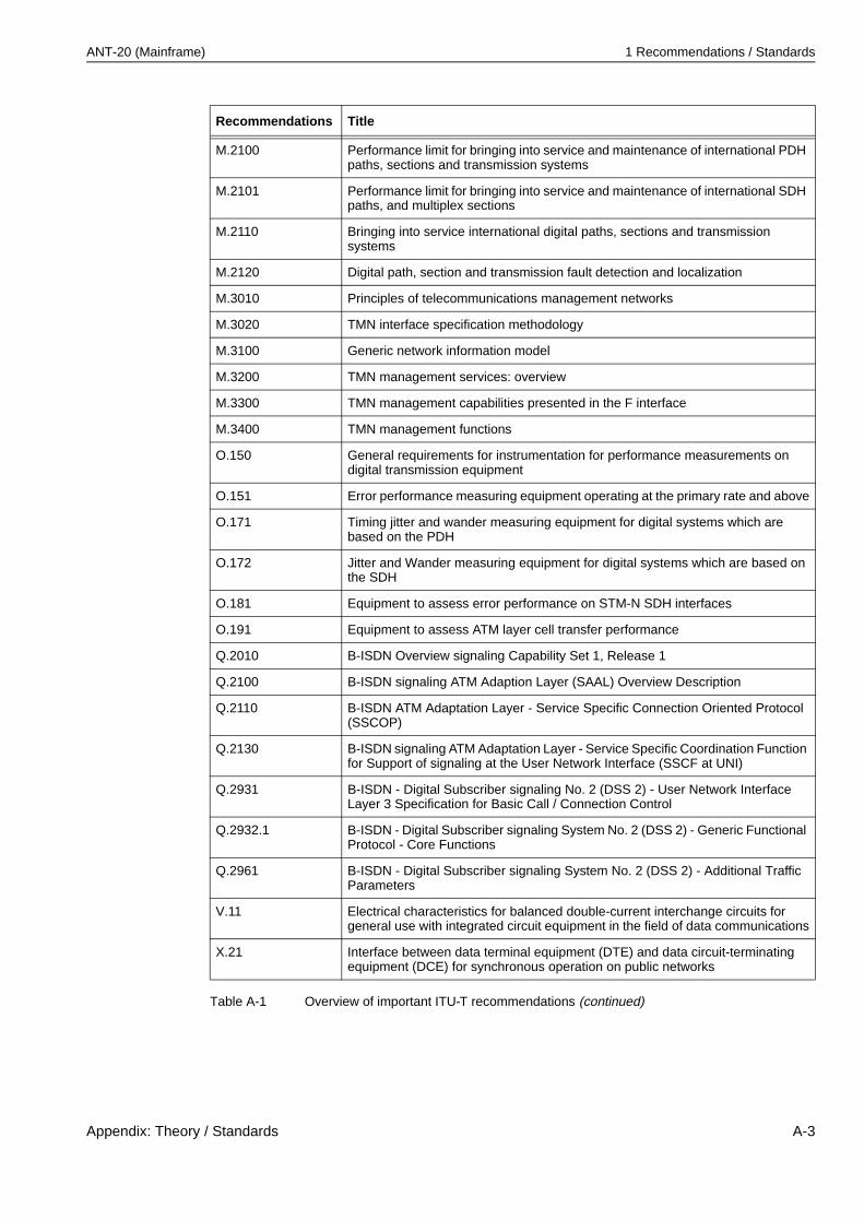
ANT-20 (Mainframe) 1 Recommendations / Standards
M.2100 Performance limit for bringing into service and maintenance of international PDH paths, sections and transmission systems
M.2101 Performance limit for bringing into service and maintenance of international SDH paths, and multiplex sections
M.2110 Bringing into service international digital paths, sections and transmission systems
M.2120 Digital path, section and transmission fault detection and localization
M.3010 Principles of telecommunications management networks
M.3020 TMN interface specification methodology
M.3100 Generic network information model
M.3200 TMN management services: overview
M.3300 TMN management capabilities presented in the F interface
M.3400 TMN management functions
O.150 General requirements for instrumentation for performance measurements on digital transmission equipment
O.151 Error performance measuring equipment operating at the primary rate and above
O.171 Timing jitter and wander measuring equipment for digital systems which are based on the PDH
O.172 Jitter and Wander measuring equipment for digital systems which are based on the SDH
O.181 Equipment to assess error performance on STM-N SDH interfaces
O.191 Equipment to assess ATM layer cell transfer performance
Q.2010 B-ISDN Overview signaling Capability Set 1, Release 1
Q.2100 B-ISDN signaling ATM Adaption Layer (SAAL) Overview Description
Q.2110 B-ISDN ATM Adaptation Layer - Service Specific Connection Oriented Protocol (SSCOP)
Q.2130 B-ISDN signaling ATM Adaptation Layer - Service Specific Coordination Function for Support of signaling at the User Network Interface (SSCF at UNI)
Q.2931 B-ISDN - Digital Subscriber signaling No. 2 (DSS 2) - User Network Interface Layer 3 Specification for Basic Call / Connection Control
Q.2932.1 B-ISDN - Digital Subscriber signaling System No. 2 (DSS 2) - Generic Functional Protocol - Core Functions
Q.2961 B-ISDN - Digital Subscriber signaling System No. 2 (DSS 2) - Additional Traffic Parameters
V.11 Electrical characteristics for balanced double-current interchange circuits for general use with integrated circuit equipment in the field of data communications
X.21 Interface between data terminal equipment (DTE) and data circuit-terminating equipment (DCE) for synchronous operation on public networks
Recommendations Title
Table A-1 Overview of important ITU-T recommendations (continued)
Appendix: Theory / Standards A-3
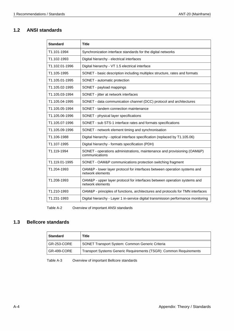
1 Recommendations / Standards ANT-20 (Mainframe)
1.2 ANSI standards
1.3 Bellcore standards
Standard Title
T1.101-1994 Synchronization interface standards for the digital networks
T1.102-1993 Digital hierarchy - electrical interfaces
T1.102.01-1996 Digital hierarchy - VT 1.5 electrical interface
T1.105-1995 SONET - basic description including multiplex structure, rates and formats
T1.105.01-1995 SONET - automatic protection
T1.105.02-1995 SONET - payload mappings
T1.105.03-1994 SONET - jitter at network interfaces
T1.105.04-1995 SONET - data communication channel (DCC) protocol and architectures
T1.105.05-1994 SONET - tandem connection maintenance
T1.105.06-1996 SONET - physical layer specifications
T1.105.07-1996 SONET - sub STS-1 interface rates and formats specifications
T1.105.09-1996 SONET - network element timing and synchronisation
T1.106-1988 Digital hierarchy - optical interface specification (replaced by T1.105.06)
T1.107-1995 Digital hierarchy - formats specification (PDH)
T1.119-1994 SONET - operations administrations, maintenance and provisioning (OAM&P) communications
T1.119.01-1995 SONET - OAM&P communications protection switching fragment
T1.204-1993 OAM&P - lower layer protocol for interfaces between operation systems and network elements
T1.208-1993 OAM&P - upper layer protocol for interfaces between operation systems and network elements
T1.210-1993 OAM&P - principles of functions, architectures and protocols for TMN interfaces
T1.231-1993 Digital hierarchy - Layer 1 in-service digital transmission performance monitoring
Table A-2 Overview of important ANSI standards
Standard Title
GR-253-CORE SONET Transport System: Common Generic Criteria
GR-499-CORE Transport Systems Generic Requirements (TSGR): Common Requirements
Table A-3 Overview of important Bellcore standards
A-4 Appendix: Theory / Standards
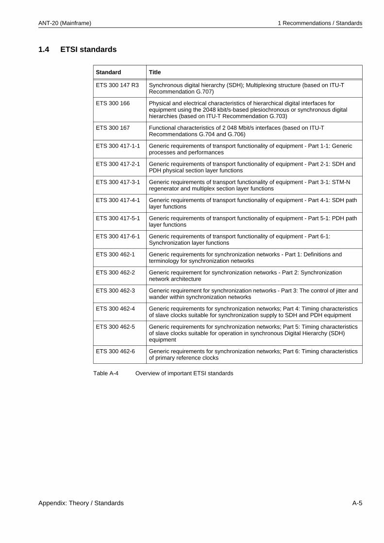
ANT-20 (Mainframe) 1 Recommendations / Standards
1.4 ETSI standards
Standard Title
ETS 300 147 R3 Synchronous digital hierarchy (SDH); Multiplexing structure (based on ITU-T Recommendation G.707)
ETS 300 166 Physical and electrical characteristics of hierarchical digital interfaces for equipment using the 2048 kbit/s-based plesiochronous or synchronous digital hierarchies (based on ITU-T Recommendation G.703)
ETS 300 167 Functional characteristics of 2 048 Mbit/s interfaces (based on ITU-T Recommendations G.704 and G.706)
ETS 300 417-1-1 Generic requirements of transport functionality of equipment - Part 1-1: Generic processes and performances
ETS 300 417-2-1 Generic requirements of transport functionality of equipment - Part 2-1: SDH and PDH physical section layer functions
ETS 300 417-3-1 Generic requirements of transport functionality of equipment - Part 3-1: STM-N regenerator and multiplex section layer functions
ETS 300 417-4-1 Generic requirements of transport functionality of equipment - Part 4-1: SDH path layer functions
ETS 300 417-5-1 Generic requirements of transport functionality of equipment - Part 5-1: PDH path layer functions
ETS 300 417-6-1 Generic requirements of transport functionality of equipment - Part 6-1: Synchronization layer functions
ETS 300 462-1 Generic requirements for synchronization networks - Part 1: Definitions and terminology for synchronization networks
ETS 300 462-2 Generic requirement for synchronization networks - Part 2: Synchronization network architecture
ETS 300 462-3 Generic requirement for synchronization networks - Part 3: The control of jitter and wander within synchronization networks
ETS 300 462-4 Generic requirements for synchronization networks; Part 4: Timing characteristics of slave clocks suitable for synchronization supply to SDH and PDH equipment
ETS 300 462-5 Generic requirements for synchronization networks; Part 5: Timing characteristics of slave clocks suitable for operation in synchronous Digital Hierarchy (SDH) equipment
ETS 300 462-6 Generic requirements for synchronization networks; Part 6: Timing characteristics of primary reference clocks
Table A-4 Overview of important ETSI standards
Appendix: Theory / Standards A-5
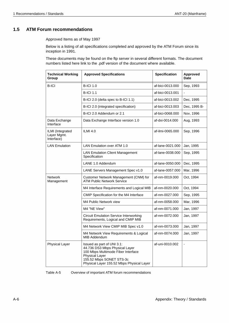
1 Recommendations / Standards ANT-20 (Mainframe)
1.5 ATM Forum recommendations
Approved Items as of May 1997
Below is a listing of all specifications completed and approved by the ATM Forum since its inception in 1991.
These documents may be found on the ftp server in several different formats. The document numbers listed here link to the .pdf version of the document where available.
Technical Working Group
Approved Specifications Specification Approved Date
B-ICI B-ICI 1.0 af-bici-0013.000 Sep, 1993
B-ICI 1.1 af-bici-0013.001 -
B-ICI 2.0 (delta spec to B-ICI 1.1) af-bici-0013.002 Dec, 1995
B-ICI 2.0 (integrated specification) af-bici-0013.003 Dec, 1995 B-
B-ICI 2.0 Addendum or 2.1 af-bici-0068.000 Nov, 1996
Data Exchange Interface
Data Exchange Interface version 1.0 af-dxi-0014.000 Aug, 1993
ILMI (Integrated Layer Mgmt. Interface)
ILMI 4.0 af-ilmi-0065.000 Sep, 1996
LAN Emulation LAN Emulation over ATM 1.0 af-lane-0021.000 Jan, 1995
LAN Emulation Client Management Specification
af-lane-0038.000 Sep, 1995
LANE 1.0 Addendum af-lane-0050.000 Dec, 1995
LANE Servers Management Spec v1.0 af-lane-0057.000 Mar, 1996
Network Management
Customer Network Management (CNM) for ATM Public Network Service
af-nm-0019.000 Oct, 1994
M4 Interface Requirements and Logical MIB af-nm-0020.000 Oct, 1994
CMIP Specification for the M4 Interface af-nm-0027.000 Sep, 1995
M4 Public Network view af-nm-0058.000 Mar, 1996
M4 "NE View" af-nm-0071.000 Jan, 1997
Circuit Emulation Service Interworking Requirements, Logical and CMIP MIB
af-nm-0072.000 Jan, 1997
M4 Network View CMIP MIB Spec v1.0 af-nm-0073.000 Jan, 1997
M4 Network View Requirements & Logical MIB Addendum
af-nm-0074.000 Jan, 1997
Physical Layer Issued as part of UNI 3.1:44.736 DS3 Mbps Physical Layer 100 Mbps Multimode Fiber Interface Physical Layer 155.52 Mbps SONET STS-3c Physical Layer 155.52 Mbps Physical Layer
af-uni-0010.002 -
Table A-5 Overview of important ATM forum recommendations
A-6 Appendix: Theory / Standards
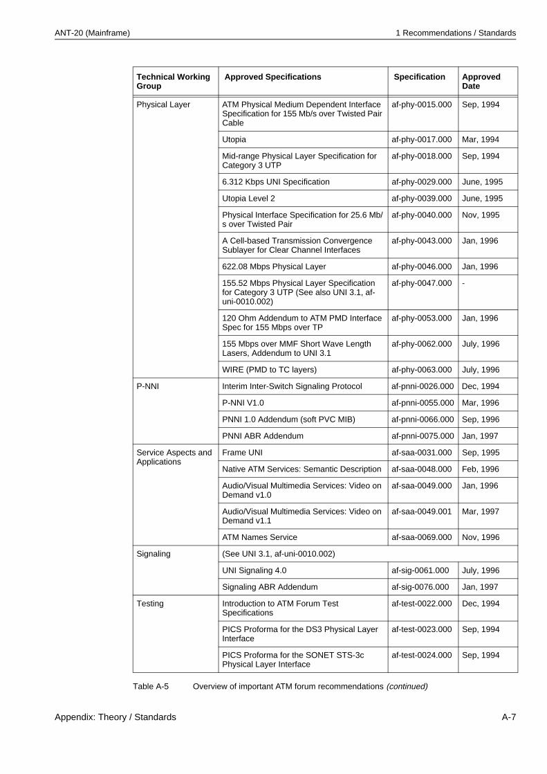
ANT-20 (Mainframe) 1 Recommendations / Standards
Physical Layer ATM Physical Medium Dependent Interface Specification for 155 Mb/s over Twisted Pair Cable
af-phy-0015.000 Sep, 1994
Utopia af-phy-0017.000 Mar, 1994
Mid-range Physical Layer Specification for Category 3 UTP
af-phy-0018.000 Sep, 1994
6.312 Kbps UNI Specification af-phy-0029.000 June, 1995
Utopia Level 2 af-phy-0039.000 June, 1995
Physical Interface Specification for 25.6 Mb/s over Twisted Pair
af-phy-0040.000 Nov, 1995
A Cell-based Transmission Convergence Sublayer for Clear Channel Interfaces
af-phy-0043.000 Jan, 1996
622.08 Mbps Physical Layer af-phy-0046.000 Jan, 1996
155.52 Mbps Physical Layer Specification for Category 3 UTP (See also UNI 3.1, af-uni-0010.002)
af-phy-0047.000 -
120 Ohm Addendum to ATM PMD Interface Spec for 155 Mbps over TP
af-phy-0053.000 Jan, 1996
155 Mbps over MMF Short Wave Length Lasers, Addendum to UNI 3.1
af-phy-0062.000 July, 1996
WIRE (PMD to TC layers) af-phy-0063.000 July, 1996
P-NNI Interim Inter-Switch Signaling Protocol af-pnni-0026.000 Dec, 1994
P-NNI V1.0 af-pnni-0055.000 Mar, 1996
PNNI 1.0 Addendum (soft PVC MIB) af-pnni-0066.000 Sep, 1996
PNNI ABR Addendum af-pnni-0075.000 Jan, 1997
Service Aspects and Applications
Frame UNI af-saa-0031.000 Sep, 1995
Native ATM Services: Semantic Description af-saa-0048.000 Feb, 1996
Audio/Visual Multimedia Services: Video on Demand v1.0
af-saa-0049.000 Jan, 1996
Audio/Visual Multimedia Services: Video on Demand v1.1
af-saa-0049.001 Mar, 1997
ATM Names Service af-saa-0069.000 Nov, 1996
Signaling (See UNI 3.1, af-uni-0010.002)
UNI Signaling 4.0 af-sig-0061.000 July, 1996
Signaling ABR Addendum af-sig-0076.000 Jan, 1997
Testing Introduction to ATM Forum Test Specifications
af-test-0022.000 Dec, 1994
PICS Proforma for the DS3 Physical Layer Interface
af-test-0023.000 Sep, 1994
PICS Proforma for the SONET STS-3c Physical Layer Interface
af-test-0024.000 Sep, 1994
Technical Working Group
Approved Specifications Specification Approved Date
Table A-5 Overview of important ATM forum recommendations (continued)
Appendix: Theory / Standards A-7

1 Recommendations / Standards ANT-20 (Mainframe)
Testing PICS Proforma for the 100 Mbps Multimode Fibre Physical Layer Interface
af-test-0025.000 Sep, 1994
PICS Proforma for the ATM Layer (UNI 3.0) af-test-0028.000 Apr, 1995
Conformance Abstract Test Suite for the ATM Layer for Intermediate Systems (UNI 3.0)
af-test-0030.000 Sep, 1995
Interoperability Test Suite for the ATM Layer (UNI 3.0)
af-test-0035.000 Apr, 1995
Interoperability Test Suites for Physical Layer: DS-3, STS-3c, 100 Mbps MMF (TAXI)
af-test-0036.000 Apr, 1995
PICS Proforma for the DS1 Physical Layer af-test-0037.000 Apr, 1995
Conformance Abstract Test Suite for the ATM Layer (End Systems) UNI 3.0
af-test-0041.000 Jan, 1996
PICS for AAL5 (ITU spec) af-test-0042.000 Jan, 1996
PICS Proforma for the 51.84 Mbps Mid-Range PHY Layer Interface
af-test-0044.000 Jan, 1996
Conformance Abstract Test Suite for the ATM Layer of Intermediate Systems (UNI 3.1)
af-test-0045.000 Jan, 1996
PICS for the 25.6 Mbps over Twisted Pair Cable (UTP-3) Physical Layer
af-test-0051.000 Mar, 1996
PICS for ATM Layer (UNI 3.1) af-test-0059.000 July, 1996
Conformance Abstract Test Suite for the UNI 3.1 ATM Layer of End Systems
af-test-0060.000 June, 1996
Conformance Abstract Test Suite for the SSCOP Sub-layer (UNI 3.1)
af-test-0067.000 Sep, 1996
PICS for the 155 Mbps over Twisted Pair Cable (UTP-5/STP-5) Physical Layer
af-test-0070.000 Nov, 1996
Traffic Management (See UNI 3.1, af-uni-0010.002)
Traffic Management 4.0 af-tm-0056.000 Apr, 1996
Traffic Management ABR Addendum af-tm-0077.000 Jan, 1997
User-Network Interface (UNI)
ATM User-Network Interface Specification V2.0
af-uni-0010.000 June, 1992
ILMI MIB for UNI 3.0 af-uni-0011.000 -
ILMI MIB for UNI 3.1 af-uni-0011.001 -
Recommendation Title
UNI 3.1 ATM User-Network Interface Specification 3.1, 4.0
CES V2.0 Circuit Emulation Services V2.0 Baseline
Table A-6 Overview of important ATM forum recommendations
Technical Working Group
Approved Specifications Specification Approved Date
Table A-5 Overview of important ATM forum recommendations (continued)
A-8 Appendix: Theory / Standards
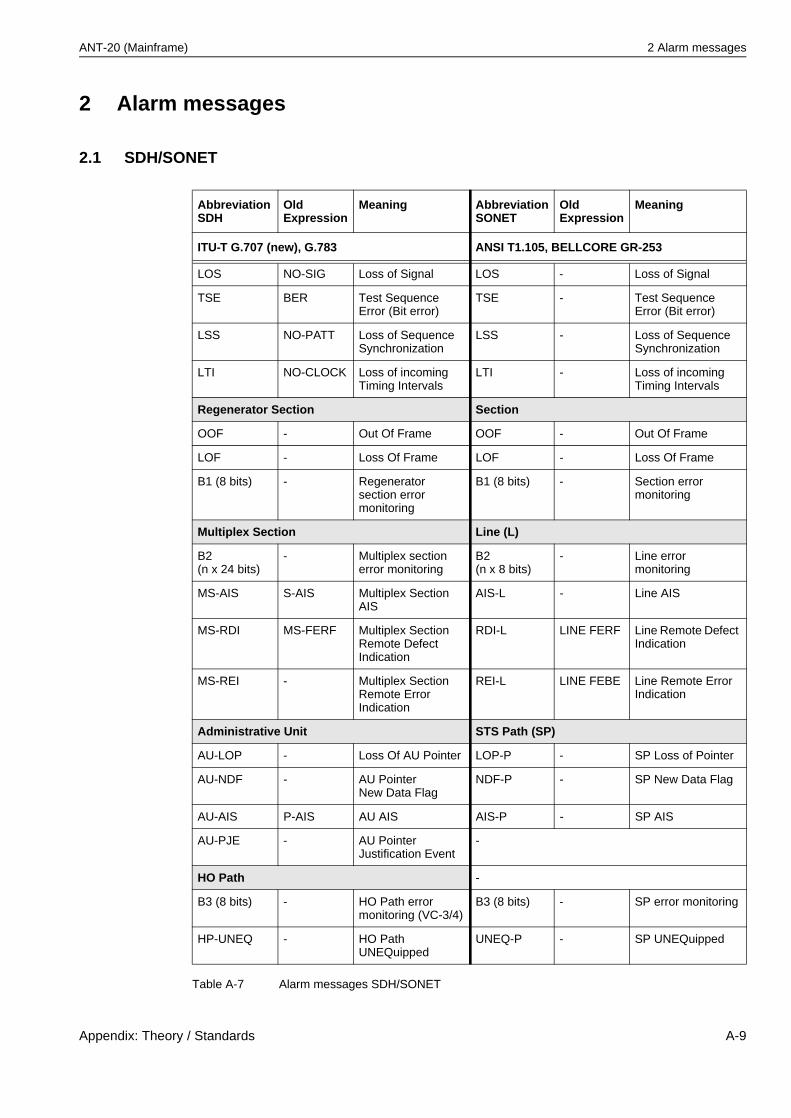
ANT-20 (Mainframe) 2 Alarm messages
2 Alarm messages
2.1 SDH/SONET
AbbreviationSDH
OldExpression
Meaning AbbreviationSONET
OldExpression
Meaning
ITU-T G.707 (new), G.783 ANSI T1.105, BELLCORE GR-253
LOS NO-SIG Loss of Signal LOS - Loss of Signal
TSE BER Test Sequence Error (Bit error)
TSE - Test Sequence Error (Bit error)
LSS NO-PATT Loss of Sequence Synchronization
LSS - Loss of Sequence Synchronization
LTI NO-CLOCK Loss of incoming Timing Intervals
LTI - Loss of incoming Timing Intervals
Regenerator Section Section
OOF - Out Of Frame OOF - Out Of Frame
LOF - Loss Of Frame LOF - Loss Of Frame
B1 (8 bits) - Regenerator section error monitoring
B1 (8 bits) - Section error monitoring
Multiplex Section Line (L)
B2(n x 24 bits)
- Multiplex section error monitoring
B2(n x 8 bits)
- Line error monitoring
MS-AIS S-AIS Multiplex Section AIS
AIS-L - Line AIS
MS-RDI MS-FERF Multiplex Section Remote Defect Indication
RDI-L LINE FERF Line Remote Defect Indication
MS-REI - Multiplex Section Remote Error Indication
REI-L LINE FEBE Line Remote Error Indication
Administrative Unit STS Path (SP)
AU-LOP - Loss Of AU Pointer LOP-P - SP Loss of Pointer
AU-NDF - AU PointerNew Data Flag
NDF-P - SP New Data Flag
AU-AIS P-AIS AU AIS AIS-P - SP AIS
AU-PJE - AU Pointer Justification Event
-
HO Path -
B3 (8 bits) - HO Path error monitoring (VC-3/4)
B3 (8 bits) - SP error monitoring
HP-UNEQ - HO Path UNEQuipped
UNEQ-P - SP UNEQuipped
Table A-7 Alarm messages SDH/SONET
Appendix: Theory / Standards A-9
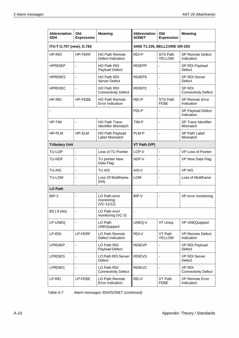
2 Alarm messages ANT-20 (Mainframe)
HP-RDI HP-FERF HO Path Remote Defect Indication
RDI-P STS Path YELLOW
SP Remote Defect Indication
HPRDIEP - HO Path RDI Payload Defect
RDIEPP - SP RDI Payload Defect
HPRDIES - HO Path RDI Server Defect
RDIEPS - SP RDI Server Defect
HPRDIEC - HO Path RDI Connectivity Defect
RDIEPC - SP RDI Connectivity Defect
HP-REI HP-FEBE HO Path Remote Error Indication
REI-P STS Path FEBE
SP Remote Error Indication
- PDI-P - SP Payload Defect Indication
HP-TIM - HO Path Trace Identifier Mismatch
TIM-P - SP Trace Identifier Mismatch
HP-PLM HP-SLM HO Path Payload Label Mismatch
PLM-P - SP Path Label Mismatch
Tributary Unit VT Path (VP)
TU-LOP - Loss of TU Pointer LOP-V - VP Loss of Pointer
TU-NDF - TU pointer New Data Flag
NDF-V - VP New Data Flag
TU-AIS - TU AIS AIS-V - VP AIS
TU-LOM - Loss Of Multiframe (H4)
LOM - Loss of Multiframe
LO Path -
BIP-2 - LO Path error monitoring(VC-11/12)
BIP-V - VP error monitoring
B3 ( 8 bits) - LO Path error monitoring (VC-3)
-
LP-UNEQ - LO Path UNEQuipped
UNEQ-V VT Uneq. VP UNEQuipped
LP-RDI LP-FERF LO Path Remote Defect Indication
RDI-V VT Path YELLOW
VP Remote Defect Indication
LPRDIEP - LO Path RDI Payload Defect
RDIEVP - VP RDI Payload Defect
LPRDIES - LO Path RDI Server Defect
RDIEVS - VP RDI Server Defect
LPRDIEC - LO Path RDI Connectivity Defect
RDIEVC - VP RDI Connectivity Defect
LP-REI LP-FEBE LO Path Remote Error Indication
REI-V VT Path FEBE
VP Remote Error Indication
AbbreviationSDH
OldExpression
Meaning AbbreviationSONET
OldExpression
Meaning
ITU-T G.707 (new), G.783 ANSI T1.105, BELLCORE GR-253
Table A-7 Alarm messages SDH/SONET (continued)
A-10 Appendix: Theory / Standards
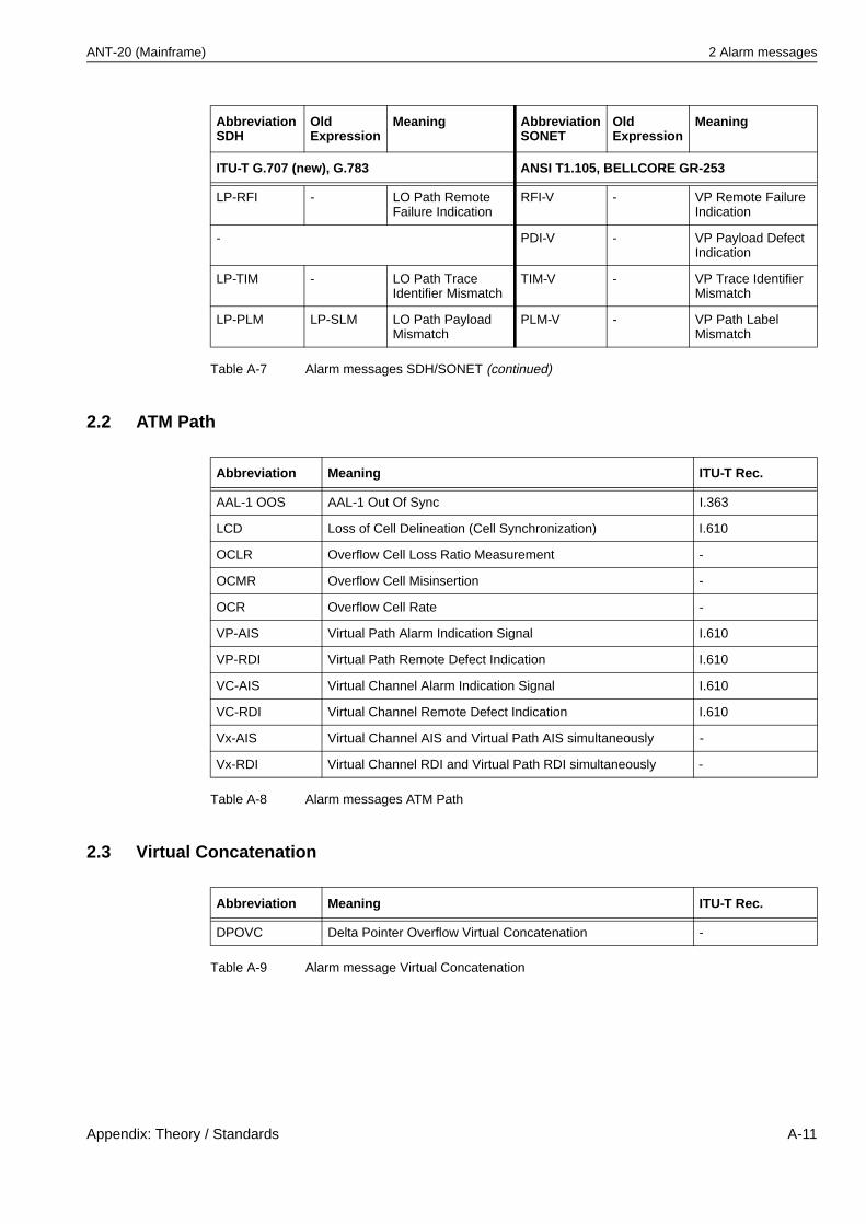
ANT-20 (Mainframe) 2 Alarm messages
2.2 ATM Path
2.3 Virtual Concatenation
LP-RFI - LO Path Remote Failure Indication
RFI-V - VP Remote Failure Indication
- PDI-V - VP Payload Defect Indication
LP-TIM - LO Path Trace Identifier Mismatch
TIM-V - VP Trace Identifier Mismatch
LP-PLM LP-SLM LO Path Payload Mismatch
PLM-V - VP Path Label Mismatch
AbbreviationSDH
OldExpression
Meaning AbbreviationSONET
OldExpression
Meaning
ITU-T G.707 (new), G.783 ANSI T1.105, BELLCORE GR-253
Table A-7 Alarm messages SDH/SONET (continued)
Abbreviation Meaning ITU-T Rec.
AAL-1 OOS AAL-1 Out Of Sync I.363
LCD Loss of Cell Delineation (Cell Synchronization) I.610
OCLR Overflow Cell Loss Ratio Measurement -
OCMR Overflow Cell Misinsertion -
OCR Overflow Cell Rate -
VP-AIS Virtual Path Alarm Indication Signal I.610
VP-RDI Virtual Path Remote Defect Indication I.610
VC-AIS Virtual Channel Alarm Indication Signal I.610
VC-RDI Virtual Channel Remote Defect Indication I.610
Vx-AIS Virtual Channel AIS and Virtual Path AIS simultaneously -
Vx-RDI Virtual Channel RDI and Virtual Path RDI simultaneously -
Table A-8 Alarm messages ATM Path
Abbreviation Meaning ITU-T Rec.
DPOVC Delta Pointer Overflow Virtual Concatenation -
Table A-9 Alarm message Virtual Concatenation
Appendix: Theory / Standards A-11
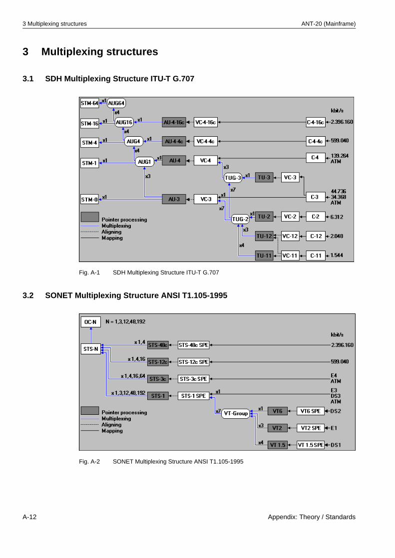
3 Multiplexing structures ANT-20 (Mainframe)
3 Multiplexing structures
3.1 SDH Multiplexing Structure ITU-T G.707
Fig. A-1 SDH Multiplexing Structure ITU-T G.707
3.2 SONET Multiplexing Structure ANSI T1.105-1995
Fig. A-2 SONET Multiplexing Structure ANSI T1.105-1995
A-12 Appendix: Theory / Standards
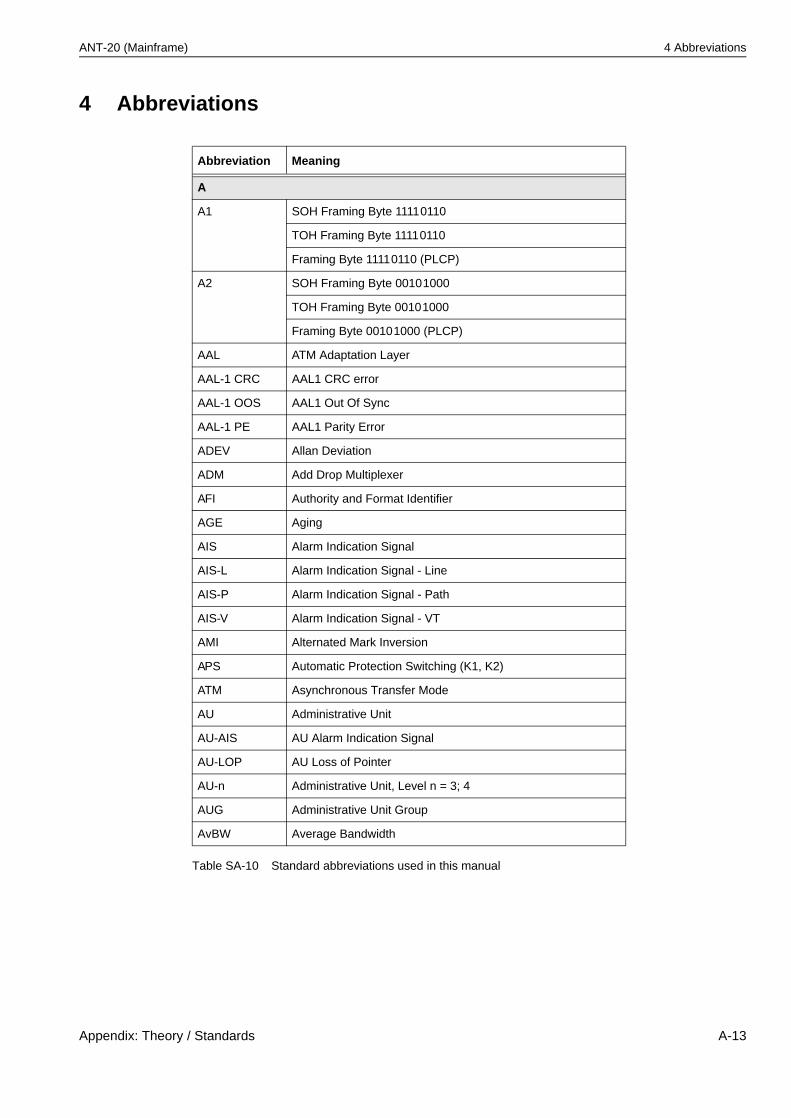
ANT-20 (Mainframe) 4 Abbreviations
4 Abbreviations
Abbreviation Meaning
A
A1 SOH Framing Byte 11110110
TOH Framing Byte 11110110
Framing Byte 11110110 (PLCP)
A2 SOH Framing Byte 00101000
TOH Framing Byte 00101000
Framing Byte 00101000 (PLCP)
AAL ATM Adaptation Layer
AAL-1 CRC AAL1 CRC error
AAL-1 OOS AAL1 Out Of Sync
AAL-1 PE AAL1 Parity Error
ADEV Allan Deviation
ADM Add Drop Multiplexer
AFI Authority and Format Identifier
AGE Aging
AIS Alarm Indication Signal
AIS-L Alarm Indication Signal - Line
AIS-P Alarm Indication Signal - Path
AIS-V Alarm Indication Signal - VT
AMI Alternated Mark Inversion
APS Automatic Protection Switching (K1, K2)
ATM Asynchronous Transfer Mode
AU Administrative Unit
AU-AIS AU Alarm Indication Signal
AU-LOP AU Loss of Pointer
AU-n Administrative Unit, Level n = 3; 4
AUG Administrative Unit Group
AvBW Average Bandwidth
Table SA-10 Standard abbreviations used in this manual
Appendix: Theory / Standards A-13
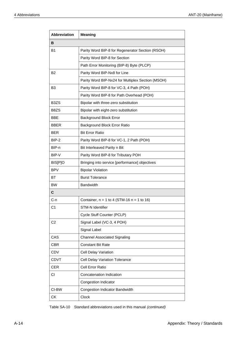
4 Abbreviations ANT-20 (Mainframe)
B
B1 Parity Word BIP-8 for Regenerator Section (RSOH)
Parity Word BIP-8 for Section
Path Error Monitoring (BIP-8) Byte (PLCP)
B2 Parity Word BIP-Nx8 for Line
Parity Word BIP-Nx24 for Multiplex Section (MSOH)
B3 Parity Word BIP-8 for VC-3, 4 Path (POH)
Parity Word BIP-8 for Path Overhead (POH)
B3ZS Bipolar with three-zero substitution
B8ZS Bipolar with eight-zero substitution
BBE Background Block Error
BBER Background Block Error Ratio
BER Bit Error Ratio
BIP-2 Parity Word BIP-8 for VC-1, 2 Path (POH)
BIP-n Bit Interleaved Parity n Bit
BIP-V Parity Word BIP-8 for Tributary POH
BIS[P]O Bringing into service [performance] objectives
BPV Bipolar Violation
BT Burst Tolerance
BW Bandwidth
C
C-n Container, n = 1 to 4 (STM-16 n = 1 to 16)
C1 STM-N Identifier
Cycle Stuff Counter (PCLP)
C2 Signal Label (VC-3, 4 POH)
Signal Label
CAS Channel Associated Signaling
CBR Constant Bit Rate
CDV Cell Delay Variation
CDVT Cell Delay Variation Tolerance
CER Cell Error Ratio
CI Concatenation Indication
Congestion Indicator
CI-BW Congestion Indicator Bandwidth
CK Clock
Abbreviation Meaning
Table SA-10 Standard abbreviations used in this manual (continued)
A-14 Appendix: Theory / Standards
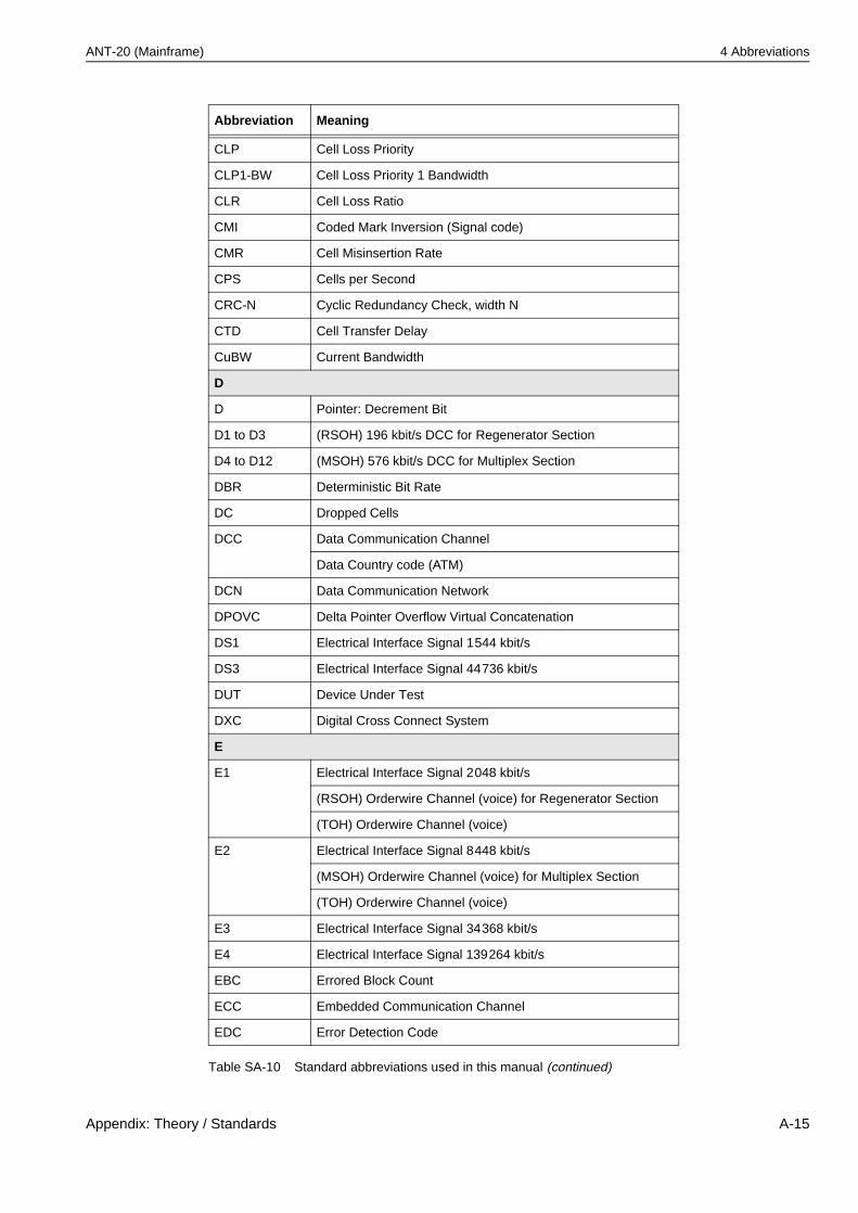
ANT-20 (Mainframe) 4 Abbreviations
CLP Cell Loss Priority
CLP1-BW Cell Loss Priority 1 Bandwidth
CLR Cell Loss Ratio
CMI Coded Mark Inversion (Signal code)
CMR Cell Misinsertion Rate
CPS Cells per Second
CRC-N Cyclic Redundancy Check, width N
CTD Cell Transfer Delay
CuBW Current Bandwidth
D
D Pointer: Decrement Bit
D1 to D3 (RSOH) 196 kbit/s DCC for Regenerator Section
D4 to D12 (MSOH) 576 kbit/s DCC for Multiplex Section
DBR Deterministic Bit Rate
DC Dropped Cells
DCC Data Communication Channel
Data Country code (ATM)
DCN Data Communication Network
DPOVC Delta Pointer Overflow Virtual Concatenation
DS1 Electrical Interface Signal 1544 kbit/s
DS3 Electrical Interface Signal 44736 kbit/s
DUT Device Under Test
DXC Digital Cross Connect System
E
E1 Electrical Interface Signal 2048 kbit/s
(RSOH) Orderwire Channel (voice) for Regenerator Section
(TOH) Orderwire Channel (voice)
E2 Electrical Interface Signal 8448 kbit/s
(MSOH) Orderwire Channel (voice) for Multiplex Section
(TOH) Orderwire Channel (voice)
E3 Electrical Interface Signal 34368 kbit/s
E4 Electrical Interface Signal 139264 kbit/s
EBC Errored Block Count
ECC Embedded Communication Channel
EDC Error Detection Code
Abbreviation Meaning
Table SA-10 Standard abbreviations used in this manual (continued)
Appendix: Theory / Standards A-15
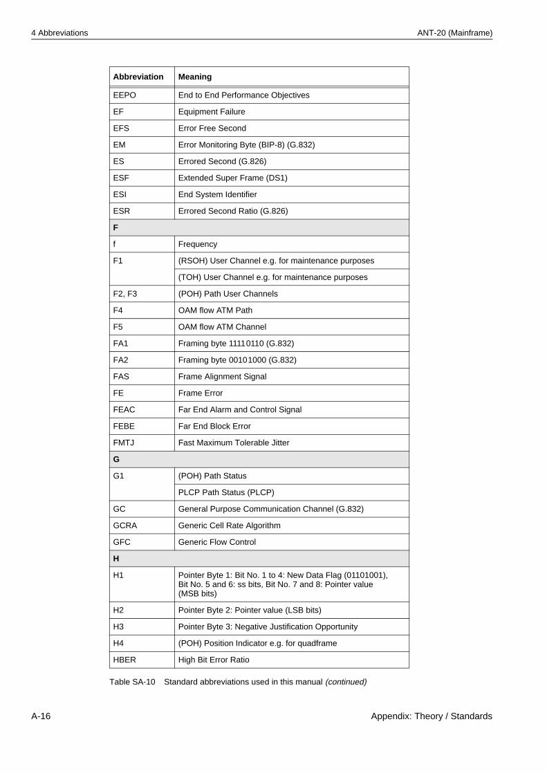
4 Abbreviations ANT-20 (Mainframe)
EEPO End to End Performance Objectives
EF Equipment Failure
EFS Error Free Second
EM Error Monitoring Byte (BIP-8) (G.832)
ES Errored Second (G.826)
ESF Extended Super Frame (DS1)
ESI End System Identifier
ESR Errored Second Ratio (G.826)
F
f Frequency
F1 (RSOH) User Channel e.g. for maintenance purposes
(TOH) User Channel e.g. for maintenance purposes
F2, F3 (POH) Path User Channels
F4 OAM flow ATM Path
F5 OAM flow ATM Channel
FA1 Framing byte 11110110 (G.832)
FA2 Framing byte 00101000 (G.832)
FAS Frame Alignment Signal
FE Frame Error
FEAC Far End Alarm and Control Signal
FEBE Far End Block Error
FMTJ Fast Maximum Tolerable Jitter
G
G1 (POH) Path Status
PLCP Path Status (PLCP)
GC General Purpose Communication Channel (G.832)
GCRA Generic Cell Rate Algorithm
GFC Generic Flow Control
H
H1 Pointer Byte 1: Bit No. 1 to 4: New Data Flag (01101001), Bit No. 5 and 6: ss bits, Bit No. 7 and 8: Pointer value (MSB bits)
H2 Pointer Byte 2: Pointer value (LSB bits)
H3 Pointer Byte 3: Negative Justification Opportunity
H4 (POH) Position Indicator e.g. for quadframe
HBER High Bit Error Ratio
Abbreviation Meaning
Table SA-10 Standard abbreviations used in this manual (continued)
A-16 Appendix: Theory / Standards
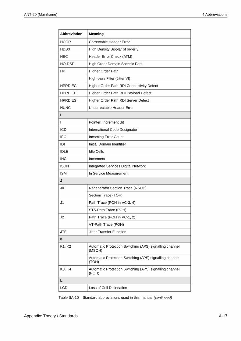
ANT-20 (Mainframe) 4 Abbreviations
HCOR Correctable Header Error
HDB3 High Density Bipolar of order 3
HEC Header Error Check (ATM)
HO-DSP High Order Domain Specific Part
HP Higher Order Path
High-pass Filter (Jitter VI)
HPRDIEC Higher Order Path RDI Connectivity Defect
HPRDIEP Higher Order Path RDI Payload Defect
HPRDIES Higher Order Path RDI Server Defect
HUNC Uncorrectable Header Error
I
I Pointer: Increment Bit
ICD International Code Designator
IEC Incoming Error Count
IDI Initial Domain Identifier
IDLE Idle Cells
INC Increment
ISDN Integrated Services Digital Network
ISM In Service Measurement
J
J0 Regenerator Section Trace (RSOH)
Section Trace (TOH)
J1 Path Trace (POH in VC-3, 4)
STS-Path Trace (POH)
J2 Path Trace (POH in VC-1, 2)
VT-Path Trace (POH)
JTF Jitter Transfer Function
K
K1, K2 Automatic Protection Switching (APS) signalling channel (MSOH)
Automatic Protection Switching (APS) signalling channel (TOH)
K3, K4 Automatic Protection Switching (APS) signalling channel (POH)
L
LCD Loss of Cell Delineation
Abbreviation Meaning
Table SA-10 Standard abbreviations used in this manual (continued)
Appendix: Theory / Standards A-17
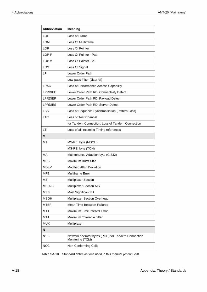
4 Abbreviations ANT-20 (Mainframe)
LOF Loss of Frame
LOM Loss Of Multiframe
LOP Loss Of Pointer
LOP-P Loss Of Pointer - Path
LOP-V Loss Of Pointer - VT
LOS Loss Of Signal
LP Lower Order Path
Low-pass Filter (Jitter VI)
LPAC Loss of Performance Access Capability
LPRDIEC Lower Order Path RDI Connectivity Defect
LPRDIEP Lower Order Path RDI Payload Defect
LPRDIES Lower Order Path RDI Server Defect
LSS Loss of Sequence Synchronisation (Pattern Loss)
LTC Loss of Test Channel
for Tandem Connection: Loss of Tandem Connection
LTI Loss of all Incoming Timing references
M
M1 MS-REI byte (MSOH)
MS-REI byte (TOH)
MA Maintenance Adaption byte (G.832)
MBS Maximum Burst Size
MDEV Modified Allan Deviation
MFE Multiframe Error
MS Multiplexer Section
MS-AIS Multiplexer Section AIS
MSB Most Significant Bit
MSOH Multiplexer Section Overhead
MTBF Mean Time Between Failures
MTIE Maximum Time Interval Error
MTJ Maximum Tolerable Jitter
MUX Multiplexer
N
N1, 2 Network operator bytes (POH) for Tandem Connection Monitoring (TCM)
NCC Non-Conforming Cells
Abbreviation Meaning
Table SA-10 Standard abbreviations used in this manual (continued)
A-18 Appendix: Theory / Standards
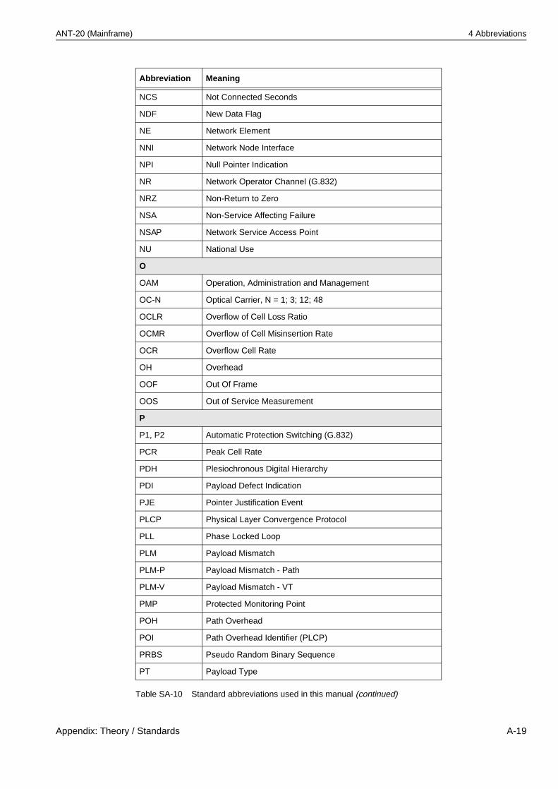
ANT-20 (Mainframe) 4 Abbreviations
NCS Not Connected Seconds
NDF New Data Flag
NE Network Element
NNI Network Node Interface
NPI Null Pointer Indication
NR Network Operator Channel (G.832)
NRZ Non-Return to Zero
NSA Non-Service Affecting Failure
NSAP Network Service Access Point
NU National Use
O
OAM Operation, Administration and Management
OC-N Optical Carrier, N = 1; 3; 12; 48
OCLR Overflow of Cell Loss Ratio
OCMR Overflow of Cell Misinsertion Rate
OCR Overflow Cell Rate
OH Overhead
OOF Out Of Frame
OOS Out of Service Measurement
P
P1, P2 Automatic Protection Switching (G.832)
PCR Peak Cell Rate
PDH Plesiochronous Digital Hierarchy
PDI Payload Defect Indication
PJE Pointer Justification Event
PLCP Physical Layer Convergence Protocol
PLL Phase Locked Loop
PLM Payload Mismatch
PLM-P Payload Mismatch - Path
PLM-V Payload Mismatch - VT
PMP Protected Monitoring Point
POH Path Overhead
POI Path Overhead Identifier (PLCP)
PRBS Pseudo Random Binary Sequence
PT Payload Type
Abbreviation Meaning
Table SA-10 Standard abbreviations used in this manual (continued)
Appendix: Theory / Standards A-19
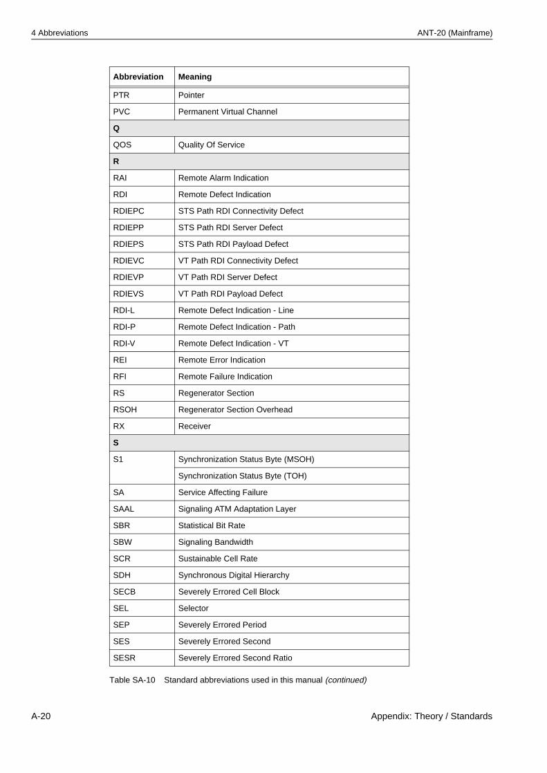
4 Abbreviations ANT-20 (Mainframe)
PTR Pointer
PVC Permanent Virtual Channel
Q
QOS Quality Of Service
R
RAI Remote Alarm Indication
RDI Remote Defect Indication
RDIEPC STS Path RDI Connectivity Defect
RDIEPP STS Path RDI Server Defect
RDIEPS STS Path RDI Payload Defect
RDIEVC VT Path RDI Connectivity Defect
RDIEVP VT Path RDI Server Defect
RDIEVS VT Path RDI Payload Defect
RDI-L Remote Defect Indication - Line
RDI-P Remote Defect Indication - Path
RDI-V Remote Defect Indication - VT
REI Remote Error Indication
RFI Remote Failure Indication
RS Regenerator Section
RSOH Regenerator Section Overhead
RX Receiver
S
S1 Synchronization Status Byte (MSOH)
Synchronization Status Byte (TOH)
SA Service Affecting Failure
SAAL Signaling ATM Adaptation Layer
SBR Statistical Bit Rate
SBW Signaling Bandwidth
SCR Sustainable Cell Rate
SDH Synchronous Digital Hierarchy
SECB Severely Errored Cell Block
SEL Selector
SEP Severely Errored Period
SES Severely Errored Second
SESR Severely Errored Second Ratio
Abbreviation Meaning
Table SA-10 Standard abbreviations used in this manual (continued)
A-20 Appendix: Theory / Standards
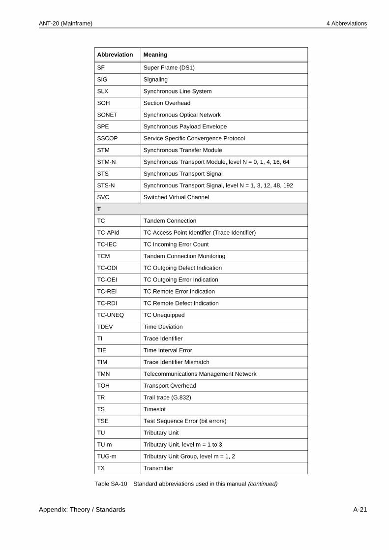
ANT-20 (Mainframe) 4 Abbreviations
SF Super Frame (DS1)
SIG Signaling
SLX Synchronous Line System
SOH Section Overhead
SONET Synchronous Optical Network
SPE Synchronous Payload Envelope
SSCOP Service Specific Convergence Protocol
STM Synchronous Transfer Module
STM-N Synchronous Transport Module, level N = 0, 1, 4, 16, 64
STS Synchronous Transport Signal
STS-N Synchronous Transport Signal, level N = 1, 3, 12, 48, 192
SVC Switched Virtual Channel
T
TC Tandem Connection
TC-APId TC Access Point Identifier (Trace Identifier)
TC-IEC TC Incoming Error Count
TCM Tandem Connection Monitoring
TC-ODI TC Outgoing Defect Indication
TC-OEI TC Outgoing Error Indication
TC-REI TC Remote Error Indication
TC-RDI TC Remote Defect Indication
TC-UNEQ TC Unequipped
TDEV Time Deviation
TI Trace Identifier
TIE Time Interval Error
TIM Trace Identifier Mismatch
TMN Telecommunications Management Network
TOH Transport Overhead
TR Trail trace (G.832)
TS Timeslot
TSE Test Sequence Error (bit errors)
TU Tributary Unit
TU-m Tributary Unit, level m = 1 to 3
TUG-m Tributary Unit Group, level m = 1, 2
TX Transmitter
Abbreviation Meaning
Table SA-10 Standard abbreviations used in this manual (continued)
Appendix: Theory / Standards A-21
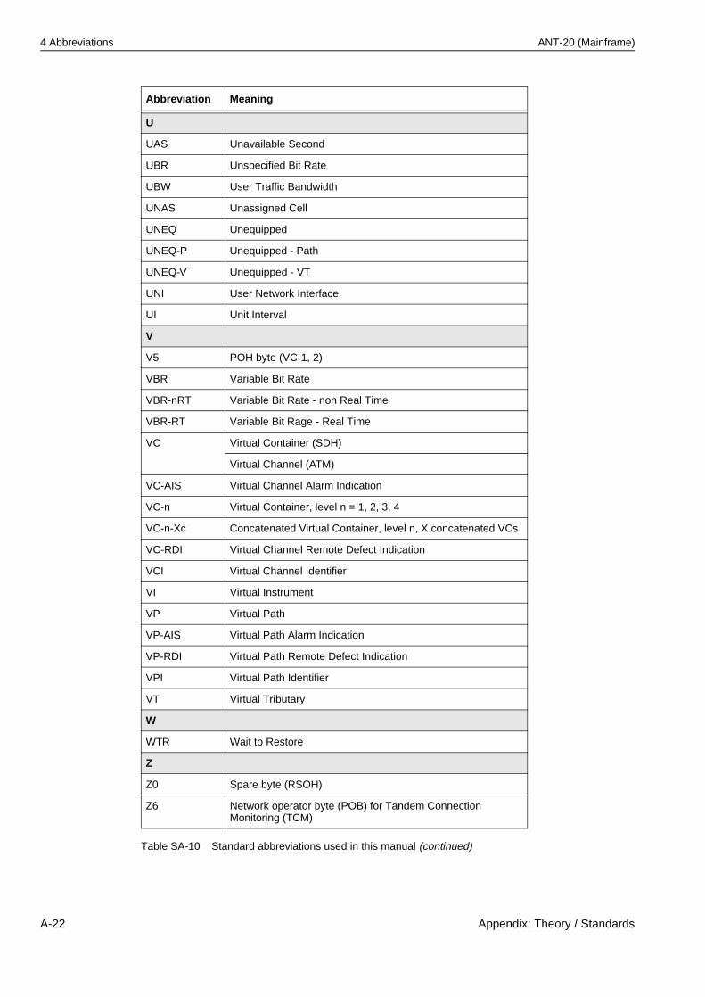
4 Abbreviations ANT-20 (Mainframe)
U
UAS Unavailable Second
UBR Unspecified Bit Rate
UBW User Traffic Bandwidth
UNAS Unassigned Cell
UNEQ Unequipped
UNEQ-P Unequipped - Path
UNEQ-V Unequipped - VT
UNI User Network Interface
UI Unit Interval
V
V5 POH byte (VC-1, 2)
VBR Variable Bit Rate
VBR-nRT Variable Bit Rate - non Real Time
VBR-RT Variable Bit Rage - Real Time
VC Virtual Container (SDH)
Virtual Channel (ATM)
VC-AIS Virtual Channel Alarm Indication
VC-n Virtual Container, level n = 1, 2, 3, 4
VC-n-Xc Concatenated Virtual Container, level n, X concatenated VCs
VC-RDI Virtual Channel Remote Defect Indication
VCI Virtual Channel Identifier
VI Virtual Instrument
VP Virtual Path
VP-AIS Virtual Path Alarm Indication
VP-RDI Virtual Path Remote Defect Indication
VPI Virtual Path Identifier
VT Virtual Tributary
W
WTR Wait to Restore
Z
Z0 Spare byte (RSOH)
Z6 Network operator byte (POB) for Tandem Connection Monitoring (TCM)
Abbreviation Meaning
Table SA-10 Standard abbreviations used in this manual (continued)
A-22 Appendix: Theory / Standards
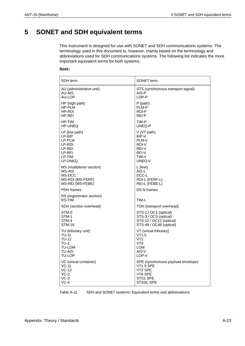
ANT-20 (Mainframe) 5 SONET and SDH equivalent terms
5 SONET and SDH equivalent terms
This instrument is designed for use with SONET and SDH communications systems. The terminology used in this document is, however, mainly based on the terminology and abbreviations used for SDH communications systems. The following list indicates the more important equivalent terms for both systems.
Note:
SDH term SONET term
AU (administrative unit)AU-AISAU-LOP
HP (high path)HP-PLMHP-RDIHP-REI
HP-TIMHP-UNEQ
LP (low path)LP-BIPLP-PLMLP-RDILP-REILP-RFILP-TIMLP-UNEQ
MS (multiplexer section)MS-AISMS-DCCMS-RDI (MS-FERF)MS-REI (MS-FEBE)
PDH frames
RS (regenerator section)RS-TIM
SOH (section overhead)
STM-0STM-1STM-4STM-16
TU (tributary unit)TU-11TU-12TU-2TU-LOMTU-AISTU-LOP
VC (virtual container)VC-11VC-12VC-2VC-3VC-4
STS (synchronous transport signal)AIS-PLOP-P
P (path)PLM-PRDI-PREI-P
TIM-PUNEQ-P
V (VT path)BIP-VPLM-VRDI-VREI-VRFI-VTIM-VUNEQ-V
L (line)AIS-LDCC-LRDI-L (FERF-L)REI-L (FEBE-L)
DS N frames
TIM-L
TOH (transport overhead)
STS-1 / OC1 (optical)STS-3 / OC3 (optical)STS-12 / OC12 (optical)STS-48 / OC48 (optical)
VT (virtual tributary)VT1.5VT2VT6LOMAIS-VLOP-V
SPE (synchronous payload envelope)VT1.5 SPEVT2 SPEVT6 SPESTS1 SPESTS3C SPE
Table A-11 SDH and SONET systems: Equivalent terms and abbreviations
Appendix: Theory / Standards A-23

5 SONET and SDH equivalent terms ANT-20 (Mainframe)
Notes:
A-24 Appendix: Theory / Standards