Part 1 – Introduction Community Based Flood Early...
51
1 1 Community Based Flood Early Warning System for the Hindu Kush Himalaya Resource Manual
Transcript of Part 1 – Introduction Community Based Flood Early...

11
Part 1 – Introduction
Community Based Flood Early Warning System for the Hindu Kush Himalaya
Resource Manual

2
Community based flood warly warning system – Resource manual
2
About ICIMOD
The International Centre for Integrated Mountain Development, ICIMOD, is a regional knowledge development
and learning centre serving the eight regional member countries of the Hindu Kush Himalayas – Afghanistan,
Bangladesh, Bhutan, China, India, Myanmar, Nepal, and Pakistan – and based in Kathmandu, Nepal.
Globalisation and climate change have an increasing influence on the stability of fragile mountain ecosystems
and the livelihoods of mountain people. ICIMOD aims to assist mountain people to understand these changes,
adapt to them, and make the most of new opportunities, while addressing upstream-downstream issues. We
support regional transboundary programmes through partnership with regional partner institutions, facilitate the
exchange of experience, and serve as a regional knowledge hub. We strengthen networking among regional
and global centres of excellence. Overall, we are working to develop an economically and environmentally
sound mountain ecosystem to improve the living standards of mountain populations and to sustain vital
ecosystem services for the billions of people living downstream – now, and for the future.
ICIMOD gratefully acknowledges the support of its core donors: the Governments of Afghanistan, Australia, Austria, Bangladesh, Bhutan, China, India, Myanmar, Nepal, Norway, Pakistan, Switzerland, and the United Kingdom.

ii
Part 1 – Introduction
Community Based Flood Early Warning System for the Hindu Kush HimalayaResource Manual
International Centre for Integrated Mountain Development, Kathmandu, November 2016
Prepared by
Neera Shrestha PradhanNarendra BajracharyaSagar Ratna BajracharyaSundar Kumar RaiDeepankar Shakya

ii
Community based flood warly warning system – Resource manual
ii
Published byInternational Centre for Integrated Mountain Development GPO Box 3226, Kathmandu, Nepal
Copyright © 2016
International Centre for Integrated Mountain Development (ICIMOD)
All rights reserved. Published 2016
ISBN 978 92 9115 427 2 (printed) 978 92 9115 428 9 (electronic)
LCCN 2016-310009
Production team
Shradha Ghale (Consultant editor)Amy Sellmyer (Editor)Dharma R Maharjan (Layout and design)Asha Kaji Thaku (Editorial assistant)
Photos: Narendra Bajracharya - cover, pp 11 (bottom L); Jitendra Raj Bacharya - pp 1, 3, 11 (bottom R) (top R); Sundar Rai - pp 3 (top L & bottom L&R), 22-23, 37 (all); Neera Shrestha Pradhan - 38
Printed and bound in Nepal by
Quality Printers Pvt. Ltd. Kathmandu, Nepal
Note
This publication may be reproduced in whole or in part and in any form for educational or non-profit purposes without special permission from the copyright holder, provided acknowledgement of the source is made. ICIMOD would appreciate receiving a copy of any publication that uses this publication as a source. No use of this publication may be made for resale or for any other commercial purpose whatsoever without prior permission in writing from ICIMOD.
The views and interpretations in this publication are those of the author(s). They are not attributable to ICIMOD and do not imply the expression of any opinion concerning the legal status of any country, territory, city or area of its authorities, or concerning the delimitation of its frontiers or boundaries, or the endorsement of any product.
This publication is available in electronic form at www.icimod.org/himaldoc
Note: The CD in the back cover contains a PDF version of this report and a video for CBFEWS instrumentation assembly.
Citation: Pradhan, NS; Bajracharya, N; Bajracharya, SR; Rai, SK; Shakya, D (2016) Community based flood early warning system – Resource manual. Kathmandu: ICIMOD

iiiiii
Part 1 – Introduction
Contents
Foreword vAcknowledgements viAbout the Resource Manual viiAcronyms and Abbreviations viii
Part 1 Introduction 1 Background 2 What is community based flood early warning system (CBFEWS)? 2 Key elements of CBFEWS 2
Risk Knowledge and Scoping 4 Concept of risk knowledge 4 Concept of risk assessment 5 Selection of community 5 Field based assessment 6
ICIMOD’s Community based Monitoring and Early Warning 10 Introduction of instrument 10 How does it work? 14 Criteria for site selection to install CBFEWS 14 Flood monitoring 14
Information Dissemination 16 Source of early warning information 16 Recipients of early warning 16 Early warning message 16 Communication channel 16 Key actors and their roles and responsibility 18 Other actors 18 Challenges related to communication and dissemination 18
Response Capability and Resilience Building 20 Warnings respected 20 Disaster preparedness and response plans established 20 Community response capacity assessed and strengthened 20 Public awareness and education enhanced 21
Part 2 Instrumentation Details 23 Introduction of Tools and Instrument 24 Multimeter 24 Screwdriver 24 Combination pliers 24 Wire cutter 24 Nose pliers 25 Slide wrench 25 Ratchet spanner 25 Box cutter 25 File 25 Soldering iron 25

iv
Community based flood warly warning system – Resource manual
iv
Hands on Practice of Assembly and Disassembly of the Instrument 27 Unpacking 27 Assembly 27 Assembly test 28 Disassembly and packing of the instrument sets 29
Installation of Instrument in the Field 30 Pre-installation 30 Installation procedures 31 Testing 32
Operation Monitoring, Repair and Maintenance 35 Operations and monitoring 35 Fault finding and rectification 35
Additional Information on CBFEWS 37 Hands-on training on CBFEWS 37 Impact on the ground 38
References and Reading Materials 39

vv
Part 1 – Introduction
Foreword
The Hindu Kush Himalayan (HKH) region is prone to natural hazards like floods, glacial lake outburst, droughts, landslides, avalanches and earthquakes. The unstable geological conditions and steep terrain, combined with climate change and frequent extreme weather conditions, pose myriad challenges for the communities. The frequent occurrence of flash floods, one of the major natural disasters in the HKH, threatens lives, livelihoods and infrastructure, both in the mountains and downstream. Vulnerable groups like the poor, women, children, the elderly and people with disabilities often suffer the worst impacts.
Since its establishment in 1983, ICIMOD has explored different ways to reduce the risk of natural hazards and the physical and social vulnerability of people in the HKH region. The establishment of a regional flood information system (HKH-HYCOS) allowed for a timely exchange of flood data and information for reducing flood vulnerability. A wide range of information is produced to support multi-scale disaster risk reduction (DRR) systems using satellite rainfall estimation, satellite altimetry based flood early warning systems, flood inundation modelling, and model derived hydrological information. Whereas, Community Based Flood Early Warning System (CBFEWS) enabled by wireless technology is one of the promising interventions for minimizing flood risk at the community level. The initiative received the UNFCCC’s Momentum for Change 2014 Lighthouse Activity Award.
This resource manual was compiled based on ground-level experiences gathered while supporting the capacity of the practitioners and local resource persons for implementing CBFEWS in Assam, India. It is an output of the project on CBFEWS, which is supported by the governments of Norway and Sweden in India under the Himalayan Climate Change Adaptation Programme (HICAP), the Australian government through the Sustainable Development Investment Portfolio for South Asia in Nepal under the Koshi Basin Programme (KBP), The US Government through USAID and NASA under SERVIR Programme and ICIMOD’s core donors in Afghanistan.
We hope that this manual will meaningfully contribute towards implementing CBFEWS, and hence, enhance the capacity of vulnerable communities by providing them real-time flood warning and thus help reduce flood risk and save lives and livelihoods.
David Molden, PhD Director General, ICIMOD

vi
Community based flood warly warning system – Resource manual
vi
Acknowledgements
This manual is an output of the project on Community Based Flood Early Warning System (CBFEWS), which is supported by the governments of Norway and Sweden in India under the Himalayan Climate Change Adaptation Programme (HICAP), the Australian government through the Sustainable Development Investment Portfolio for South Asia in Nepal under the Koshi Basin Programme (KBP), The US Government through USAID and NASA under SERVIR Programme and ICIMOD’s core donors in Afghanistan. ICIMOD gratefully acknowledges the support of its core donors: the governments of Afghanistan, Australia, Austria, Bangladesh, Bhutan, China, India, Myanmar, Nepal, Norway, Pakistan, Switzerland, and the United Kingdom.
We are grateful to colleagues who have contributed to this manual and to all the resource persons who supported us in this effort. Our thanks are also due to the participants of the regional workshop on CBFEWS, which was instrumental in testing this manual. We sincerely thank the government organizations and partners, District Disaster Management Authority (DDMA) of Lakhimpur District and Dhemaji District, Assam, and Aaranyak in India; Focus Humanitarian in Afghanistan; and the Department of Hydrology and Metrology/Community Based Flood and Glacial Lake Outburst Risk Reduction Project (DHM/CFGORRP) in Nepal for trusting the technology developed by ICIMOD and jointly piloting it in the field. We would also like to thank Sustainable Eco Engineering (SEE), Nepal for their support in designing and manufacturing of the CBFEWS instrument.
We acknowledge the continuous support of Dr Aditi Mukherji, Theme Leader, Water and Air at ICIMOD and other colleagues from ICIMOD who supported the implementation of CBFEWS, Anja Rasmussen, Senior Manager for Knowledge Management and Communication, Nand Kishor Agrawal, HICAP Initiative Coordinator, Dr Shahriar M. Wahid, Koshi Basin Programme (KBP) Initiative Coordinator, Birendra Bajracharya, Mountain Environment Regional Information System Regional Programme Manager, Samden Sherpa, Knowledge Park Officer, Mohan Shrestha, Admin & Logistics Officer, and Professor Narendra Raj Khanal of Tribhuvan University. We thank ICIMOD’s directorate for providing strategic guidance for scaling up CBFEWS and showcasing it at the global level. Last but not the least, we would like to thank Dr Arun Bhakta Shrestha, Regional Programme Manager for River Basins and Dr Dhrupad Choudhury, Regional Programme Manager for Adaptation to Change for envisioning this project, out scaling, up scaling and providing continuous technical guidance for the success of this project.
The support from Water and Air Theme is highly acknowledged for the publication of this manual.

viivii
Part 1 – Introduction
About the Resource Manual
What is the objective of the Resource Manual?The main objective of this resource manual is to illustrate the key principle of Community Based Flood Early Warning System (CBFEWS) and its implementation.
Who is the target audience?The resource manual is primarily aimed at organizations and partners who implement CBFEWS in the field. It can also be adapted and applied by other relevant stakeholders, depending on their interest and scope.
What is the scope of the manual?Considering the various approaches of flood early warning system that are in place, this resource manual focuses on the community based approach developed by ICIMOD together with the Sustainable Eco Engineering, and on the experiences that ICIMOD and Aaranyak gathered from the field in Assam, India. Details of the instrument and guidance for its installation (how to set up) are provided in Part 2 of the resource manual.
How is the manual organized?The manual is organized in three sections. Section 1 provides a brief background of CBFEWS and its features. It also discusses about key elements of CBFEWS including risk knowledge and scoping, ICIMOD designed CBFEWS and its monitoring and information dissemination, and response capability and resilience building. Section 2 provides details of instrument including introduction of tools that are used to fix the instrument, hands on practice of assemble and disassemble of the instrument, installation process of the instrument in the field and operating, monitoring, repairing and maintenance of the instruments. It also gives information on hands-on training and evidence about impact on the ground. Section 3 provides a list of reference materials.

viii
Community based flood warly warning system – Resource manual
viii
Acronyms and Abbreviations
AH Ampere Hour
BNC Bayonet Neill-Concelman (Antenna Connector)
CBFEWS Community-Based Flood Early Warning System
COP Conference of Parties
DAO District Administration Office
DDC District Development Committee
DDMA District Disaster Management Authority
DDRC District Disaster Relief Committee
DHM Department of Hydrology and Meteorology
DPO District Programme Officer
FRA Flood risk assessments
HICAP Himalayan Climate Change Adaptation Programme
ICIMOD International Centre for Integrated Mountain Development
ICT Information and Communications Technology
KBP Koshi Basin Programme
L1 Level 1
L2 Level 2
L3 Level 3
LED Light Emitting Diode
MHz Mega Hertz
NiMH Nickel Metal Hydride (Rechargeable Battery)
NW Network
PCB Printed Circuit Board
PV Photo voltaic
PVC Poly-Vinyl Chloride (Piping tube)
RD Ready
RFM Radio Frequency Module
RJ45 Registered Jack-45 (connector from sensor to transmitter unit)
RX Receiver
SREX Special Report on Extreme Events and Disasters
TX Transmitter
UNFCCC United Nations Framework Convention on Climate Change
UNISDR United Nations International Strategy for Disaster Reduction
V Volt
VDRMC Village Disaster Risk Management Committee
11
Part 1 – Introduction
11
Introduction1

2
Community based flood warly warning system – Resource manual
2
Background
The Hindu Kush Himalayas (HKH) make up one of the most dynamic and complex mountain systems in the world. The region is known to be extremely fragile and prone to natural hazards, which are exacerbated by climate change. Floods and flash floods are the major climate-induced natural hazards that threaten the lives and livelihoods of the downstream communities, particularly in monsoon season. Such floods can be disastrous in the small rivers and tributaries because they get less attention from the government and other concerned agencies. Early warnings are developed at the global, regional or national level to provide flood information. However, according to Hyogo Protocol and the UNFCCC’s Special Report on Extreme Events and Disasters (SREX 2012), the main gap arises from the fact that the information does not reach the most vulnerable communities.
What is community based flood early warning system (CBFEWS)?UNEP (2012) defines early warning as “the provision of timely and effective information, through identified institutions, that allows individuals exposed to hazard to take action to avoid or reduce their risk and prepare for effective response”. Early warning is defined by UNISDR as “the set of capacities needed to generate and disseminate timely and meaningful warning information to enable individuals, communities and organizations threatened by hazards to take necessary preparedness measures and act appropriately in sufficient time to reduce possibility of harms or losses” (ISDR 2006).
Community based flood early warning system (CBFEWS) is an integrated system of tools and plans managed by and for communities, providing real-time flood warnings to reduce flood risks. CBFEWS is based on people-centered, timely, simple and low-cost technology. It disseminates information to the vulnerable communities downstream through a network of communities and government bodies. A properly designed and implemented system can save lives and reduce property loss by increasing the lead time to prepare and respond to flood on ground level.
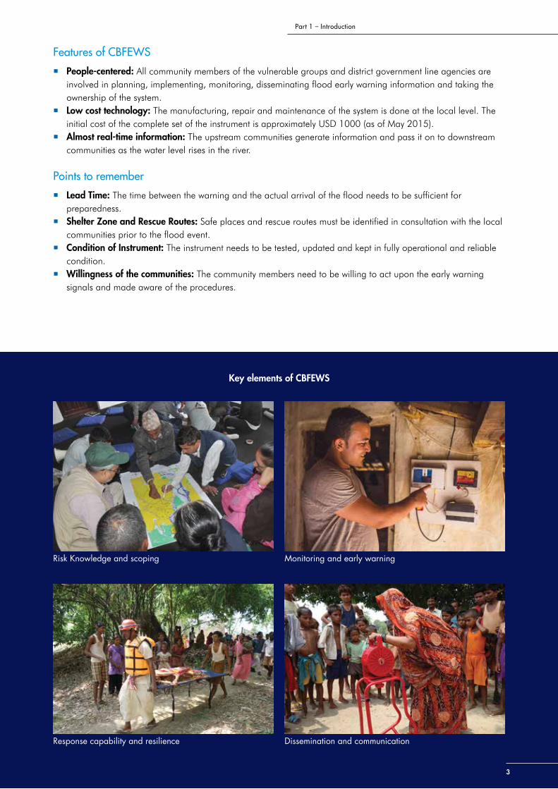
Key elements of CBFEWSThe United Nations International Strategy for Disaster Reduction (UNISDR) Platform for the Promotion of Early Warning has identified four key elements for a complete and effective early warning system. Based on UNISDR’s four key elements, CBFEWS has also defined four key elements for its implementation (Figure 1). An isolated approach cannot make the CBFEWS successful. It is important to understand that these four elements are interrelated and failure in one element can result in failure of the entire system. The detail is given in the next sections.
Risk Knowledge and Scoping
Systematically collect data and undertake risk assessments and scoping
Community Based Monitoring and Early Warning
Install early warning instrument and flood monitoring by upstream communities
Dissemination and Communication
Communicate flood information by upstream and provide early warnings to downstream communities
Response Capability and Resilience
Enhance community response capabilities and build resilience
Figure 1: Four elements of CBFEWS
Source: Based on UNISDR, 2006
33
Part 1 – Introduction
Features of CBFEWS
People-centered: All community members of the vulnerable groups and district government line agencies are involved in planning, implementing, monitoring, disseminating flood early warning information and taking the ownership of the system.
Low cost technology: The manufacturing, repair and maintenance of the system is done at the local level. The initial cost of the complete set of the instrument is approximately USD 1000 (as of May 2015).
Almost real-time information: The upstream communities generate information and pass it on to downstream communities as the water level rises in the river.
Points to remember
Lead Time: The time between the warning and the actual arrival of the flood needs to be sufficient for preparedness.
Shelter Zone and Rescue Routes: Safe places and rescue routes must be identified in consultation with the local communities prior to the flood event.
Condition of Instrument: The instrument needs to be tested, updated and kept in fully operational and reliable condition.
Willingness of the communities: The community members need to be willing to act upon the early warning signals and made aware of the procedures.
Key elements of CBFEWS
Risk Knowledge and scoping
Response capability and resilience
Monitoring and early warning
Dissemination and communication

4
Community based flood warly warning system – Resource manual
4
Risk Knowledge and Scoping
A detailed risk assessment is conducted through systematic data collection and analysis of hazards, vulnerabilities and existing capacity of the community. This helps us understand the situation, motivate people, prioritize needs for developing early warning systems and guide preparations of disaster prevention and response measures.
Source: UNISDR 2002:41, as cited in USAID, 2011
Concept of risk knowledge Flood, which is a natural hazard, would not become a disaster if we can reduce the loss of life and minimize human suffering by being prepared and aware of how to deal with it. For this, we need to understand the nature (Table 1), frequency, severity and lead time of flood.
Nature of flood hazard
There are two types of flood hazards:
Frequency and severity of hazard
The severity of flood hazard is determined in terms of casualties and heavy loss of lives and properties. It depends on the following criteria (Table 2).
Lead time
Lead time in flood forecasting refers to the amount of time a flood takes to reach a particular downstream community from the flood measurement station upstream. The basic principle for assessing lead time is that advance warning should be given with enough time for effective preparatory action. This depends on the need of the target community and area, type of catchment structure, catchment size, catchment response for a given rainfall and the catchment lag time (time taken by runoff from the furthest corner of the catchment to the point of interest, which translates into longer lag times for larger catchments).
Risk =Coping Capacity
Hazard x Vulnerability
Objectives
1. Identify risk zones2. Identify vulnerable
communities3. Identify safe shelter zone
and rescue routes
Table 1: Nature of flood hazard
Flash Flood Riverine Flood
• Caused by sudden flooding in small river basins for a short duration with a relatively high peak discharge
• Occurs within six hours or less after heavy rainfall event• Occurs in normally dry areas with no visible stream
channel• Occurs normally as a result of the runoff from a
torrential downpour• Occurs from the failure of landslide dam lakes,
GLOF or sudden break-up of ice jams or other river obstructions
• Caused by heavy rain over long periods (days) in the upper catchment, leading to rising water levels
• Rainfall over large catchment areas• Melting of the winter snow accumulation • Takes place in river systems with tributaries
that may drain large geographic areas and encompass many independent river basins
• Normally has a slow build-up• Is often seasonal• May continue for days or weeks
Source: Katyal, A. K., & Petrisor, I. G. (2011); DWIDP, 2009

55
Part 1 – Introduction
Concept of risk assessmentAssessment is a process that involves all concerned parties in the collection and analysis of information about flood risk and special measures for addressing them. Different participatory mapping tools can be used as per the need of the community and the objectives of the assessment (Table 3).
Selection of community Selecting a community is the first step in establishing a community based flood early warning system. The selection depends on various factors such as the communities which often suffer the most as a result of flood, marginalize and low income groups, people less access to resources, people living in a community lacking provision for flood protection, people more affected by and less able to cope with floods (for instance infants, disable, old, language barriers etc.). Most important criteria is, communities who are residing on or near to floodplains. Simultaneously
Table 2: Indicators of flood severity
Location and spatial dimension of flood
An overview of the potential flooded areas can be obtained using maps (topographic maps of the area, maps held by the local authorities or maps produced by or with assistance of the community at risk). The official maps will complement the maps produced by the community.
Depth of the flood It can be measured using various sources, such as interviews with local people about their experiences, historical information on the intensity and magnitude of floods, and information on the extent and depth of previous flood events or flood predictions, and flood marks.
Duration of the flood It is the rate at which flooding is likely to occur (i.e., rapid onset or slow rise of flood water) and how long the flood event lasts (few minutes, few hours, 1 day, 2 days, etc.). The number of casualties and extend of the damage depend on the duration of the flood.
Velocity of the flood It is the speed of the flow of water. Floating debris and materials are indicators of strong currents. Ask people about their experience of the flood current. Strong currents might be dangerous and people should not live in houses because during such a strong current houses might collapse due to high velocity flood when houses are inundate in flood water
Source: DWIDP, 2009
Table 3: Tools for mapping of resources
Assessment Tools
Hazard assessment • Social mapping (house, road, temples, etc.)• Hazard mapping (natural hazard areas, safe areas, etc.)• Resource mapping (schools, health centres, religious facilities, open field, market,
forest, safe areas, etc.)• Field survey (interview, focus group discussions, direct observations)• High resolution satellite image and field verification (location of bank failure, existing
measures, sites of sand mining and its surroundings, former and new channel courses, river bank encroachment, etc.)
Vulnerability assessment
• Participatory situation analysis is conducted based on hazard assessment, location of the vulnerable community, most vulnerable groups (people with disability, children, women, elderly people), routes and accessibility to evacuation shelter, infrastructure, land use, population at risk, etc.
• Ranking is done for each parameter to determine the maximum and minimum vulnerability.
Capacity assessment • Seasonal calendar (duration and timing of hazards and vulnerability; community members’ work schedule, etc.)
• Venn diagrams (organizations, their roles and relationship with the community)
6
Community based flood warly warning system – Resource manual
6
there should be a consideration of vulnerability and interest, cost benefit, the effectiveness and need of the system, etc. In addition, one of the most important criteria for CBFEWS developed by ICIMOD is the existence of an upstream community to install the instrument, take care of it and disseminate flood information downstream. Refer to Section 3 for site selection criteria for installation.
After selecting the community and installation site, the next step is to build rapport with the communities and concerned stakeholders. It is necessary to build trust and friendship with the local communities so that they can share their issues, problems and concerns. Rapport building also helps us understand the local context such as local culture, norms and values, power relations and peoples’ perceptions, which are absolutely essential for the establishment of a successful CBFEWS. Being friendly, transparent, motivated and patient while interacting with the local people is crucial for gaining their trust. The concept, its scope, process, limitations, and roles and responsibilities need to be discussed through community consultations and disseminated through awareness raising tools such as posters, flyers and information sheets.
Field based assessmentThe field-based assessment includes the following steps.
Hazard assessment
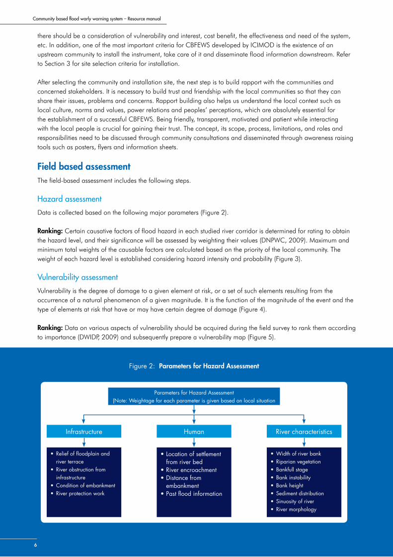
Data is collected based on the following major parameters (Figure 2).
Ranking: Certain causative factors of flood hazard in each studied river corridor is determined for rating to obtain the hazard level, and their significance will be assessed by weighting their values (DNPWC, 2009). Maximum and minimum total weights of the causable factors are calculated based on the priority of the local community. The weight of each hazard level is established considering hazard intensity and probability (Figure 3).
Vulnerability assessment
Vulnerability is the degree of damage to a given element at risk, or a set of such elements resulting from the occurrence of a natural phenomenon of a given magnitude. It is the function of the magnitude of the event and the type of elements at risk that have or may have certain degree of damage (Figure 4).
Ranking: Data on various aspects of vulnerability should be acquired during the field survey to rank them according to importance (DWIDP, 2009) and subsequently prepare a vulnerability map (Figure 5).
Figure 2: Parameters for Hazard Assessment
Parameters for Hazard Assessment(Note: Weightage for each parameter is given based on local situation
Infrastructure
• Relief of floodplain and river terrace
• River obstruction from infrastructure
• Condition of embankment• River protection work
• Location of settlement from river bed
• River encroachment• Distance from
embankment• Past flood information
• Width of river bank• Riparian vegetation• Bankfull stage• Bank instability• Bank height• Sediment distribution• Sinuosity of river• River morphology
Human River characteristics

77
Part 1 – Introduction
Figure 4: Parameters for vulnerability mapping
Parameters for vulnerability Mapping(Weightage for each parameter is given based on
local situation and subjective judgement)
Infrastructure
• Bridge• Highway• Railway• Road• Buildings• Embankment
• Settlement• Agriculture• Urban• Barren• Forest• Grass
• Above 65 years• Children• Pregnant women• New born babies• Disable people
Land use Population
Hazard intensity
Hazard intensity
Danger to population close
to the stream
Dange to population in settlement (about 500
m from the stream)
Danger to population 1 km away from the
stream
Danger to population more than 1 km away
from the stream
High Yes Yes Yes Yes
Moderate Yes Yes Yes No
Moderately low Yes Yes No No
Low Yes Yes No No
+Hazard probability
High at least once in 10 years
Moderate once in 10 to 30 years
Moderately low once in 30 to 100 years
Low Less frequent than once in 100 years
Figure 3: Hazard Ranking
=Hazard ranking
Probability
High Moderate Moderately low Low Hazard level
Haz
ard
inte
nsity High Very high
Moderate High
Moderately low Moderate
Low Low
Source: Shrestha, 2008

88
Figure 5: Example of a field based vulnerability map, Dihiri and Kekuri villages, Assam, India
Vulnerability score
1. Less distance from embankment 12. High distance from embankment 23. High altitude 14. Low altitude 25. High distance from river 16. Less distance from river 2
Highly vulnerable
High distance from embankment 2Low altitude 2Less distance from river 2
Moderately vulnerable
High distance from embankment 2High altitude 1Less distance from river 2
Less vulnerable
Less distance from embankment 1High altitude 1Less distance from river 1
Elevation zones (in mts.)Source: ASTER DEM
km0 .15 .3 .6 .9 1.2
99-112
87-99
74-84
62-74
49-62
Embankment
Settlement clusters
River channel
94° 27’ 30”E
94° 27’ 30”E
94° 27’ 30”E
94° 27’ 30”E
94° 27’ 30”E
94° 27’ 30”E
94° 28’ 0”E
94° 28’ 0”E
94° 28’ 0”E
94° 28’ 0”E
27° 26’ 30”N
27° 26’ 0”N
27° 26’ 0”N
27° 26’ 30”N
27° 26’ 0”N
27° 26’ 0”N
N
Risk, Hazard, Vulnerability Assessment Area
km0 .15 .3 .6 .9 1.2
N
94° 27’ 30”E
94° 27’ 30”E
94° 27’ 30”E
94° 27’ 30”E
94° 27’ 30”E
94° 27’ 30”E
27° 26’ 30”N 27° 26’ 30”N
27° 26’ 0”N 27° 26’ 0”N
27° 26’ 0”N 27° 26’ 0”N
94° 28’ 0”E
94° 28’ 0”E
94° 28’ 0”E
94° 28’ 0”E
DEM of Study Area

99
Part 1 – Introduction
9
Figure 6: Parameters for capacity assessment
Parameters for capacity assessment(Weightage for each parameter is given based on local situation
and subjective judgement)
Physical/Economic
• Money/Cash• Real properties• Stable source of income and
livelihood• Safe infrastructures• Food security• Balanced nature environment• Absence of hazards
• Knowledgeable and skillful• Confidence and self-esteem• Proactive attitude• Open to change and new ideas• Continual learning• Building on experiences• Positive perception in life
• Width of river bank• Riparian vegetation• Bankfull stage• Bank instability• Bank height• Sediment distribution• Sinuosity of river• River morphology
Motivational/Attitudinal Social/Organizational
Degree of the probability of flooding in flood hazard zone Infrastructure vulnerable to flood hazard Land use vulnerability in flood hazard zone Population vulnerable to flood hazard
Capacity assessment
Capacity is the combination of all strengths, attributes and resources available within a community, society, organization that can be used to achieve agreed upon goals. Capacity may include infrastructure and physical means, institutions, society’s coping abilities, as well as human knowledge, skills and collective attributes such as social relationships, leadership and management (Figure 6).
Ranking: Capacity ranking could take the following aspects into consideration (UNDP Capacity Assessment Methodology Users’ Guide, 2008).
No evidence of relevant capacity Anecdotal evidence of capacity Partially developed capacity Widespread, but not comprehensive, evidence of capacity Fully developed capacity
Risk assessment and mapping
Risk assessment is a methodology for determining the nature and extent of risk by analysing potential hazards and evaluating existing conditions of vulnerability that could potentially harm exposed people, property, services, livelihoods and the environment on which they depend. Exposure and vulnerability are key determinants of disaster risk and of impacts when risk is realized (SREX, 2012). Communities and individuals are differently exposed and vulnerable based on the unequal levels of wealth, education, disability, health status, gender, age, class and other social and cultural parameters. For the field based risk assessment, field based flood vulnerability data, field based flood hazard data and field based capacity assessment data are analysed and risk zones are defined on a risk map.

10
Community based flood warly warning system – Resource manual
10
ICIMOD’s Community Based Monitoring and Early Warning
Note: The CBFEWS instrument is designed by experts from ICIMOD using the technology introduced by JICA and manufactured by Sustainable Eco Engineering (SEE). ICIMOD provides technical training to partners and interested stakeholders. It is requested that any use of this instrument is credited to ICIMOD.
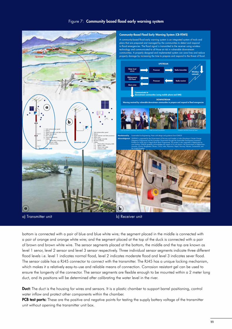
The CBFEWS developed by ICIMOD is based on a simple instrument that is installed upstream to detect flood. The system relies on cooperation between upstream communities and downstream communities. The instrument automatically generates flood signals which are communicated to the downstream communities. The system consists of two units, transmitter unit and receiver unit. The transmitter unit is installed on the river bank while the receiver unit is placed in caretaker’s house. The distance between these units should not be more than 700 meters and line of sight should be clear between them. The instrument works according to the principle of floating and conductivity. As the water level rises, the sensor attached with transmitter unit detects it and sends warning signals to the receiver unit using wireless technology that is instantly disseminated to the downstream vulnerable communities and concerned agencies via mobile phone. The system is cost effective and user-friendly technology that provides real-time flood information. The details of the transmitter and receiver unit are provided in Figure 7 and the specifications of the instrument are in Figure 8.
Introduction of instrument
Introduction of Wireless Water Level Monitoring System, Version 3 (WWLMS V3)
Wireless Water Level Monitoring System, Version 3 (WWLMS V3) is the latest modified version of water level sensing and signal transmitting device developed by ICIMOD. The version includes a modified sensor in which two types of sensors, conductivity based sensor and floating based sensor are used. In current version, not only signal transmission range between transmitter unit and receiver unit has been expanded but also efficient power system has been built so power would long last. The instrument has its own network ID. Radio Frequency Module (RFM) 12 with 433 Mega Hertz (MHz) frequency is used to transmit a signal. To avoid collision of signals between two different sets of instrument, different network IDs are used. The transmitter is denoted by TX620 and the receiver as RX620. The communication occurs only between instruments with the same identification number.
Different parts of the instrument
Sensor: The sensor (Figure 9) senses the water levels and transmits the signals to the processor of the transmitter unit. It consists of three individual sensor segments. Each segment is made up of a reed switch based Printed Circuit Board (PCB) conducting from magnetic floating barrel. Beside magnetic floating based sensor, a conductivity based sensor has also been incorporated in the sensor as an option to insure in sensing the water level. Every sensor segment has a floating magnet inside the barrel that connects the circuit while rising water level pushes the single barrel up. This connection instantly generates the signal in the system. Additionally, two electrodes of conductive sensors has been placed in each individual sensor segment that connects the electrical conductivity when the water reach the sensor segment.
Wire colour and sensor level: Each sensor set has three water level sensor segments placed vertically inside the sensor duct. The positions of individual sensor segments are determined by calibrating the actual flood level. These individual segments are connected separately with three different colorful wires. Such as, the segment placed at the
Objectives
1. Introduction of instrument2. Understand its function 3. Community based flood
forecasting and early warning
1111
Part 1 – Introduction
UPSTREAM
Regional Programme
Community-Based Flood Early Warning System (CB-FEWS)
A community-based flood early warning system is an integrated system of tools and plans that are prepared and managed by the communities to detect and respond to flood emergencies. The flood signal is transmitted to the receiver using wireless technology and communicated to all those at risk in vulnerable downstream communities. A properly designed and implemented system can save lives and reduce property damage by increasing the time to prepare and respond to the threat of flood.
Manufactured by Sustainable Eco-Engineering, Patan with design and guidance from ICIMOD
Acknowledgement CB-FEWS is supported by the Governments of Norway and Sweden in India (Himalayan Climate Change Adaptation Programme) and the Australian Government through the Sustainable Development Investment Portfolio for South Asia in Nepal (Koshi Basin Programme). This project is also supported in Afghanistan by core funding. ICIMOD gratefully acknowledges the support of its core donors: the Governments of Afghanistan, Australia, Austria, Bangladesh, Bhutan, China, India, Myanmar, Nepal, Norway, Pakistan, Switzerland, and the United Kingdom.
Water level sensor Processor Radio transmitter
Alphanumeric LCD Panel
Processor
Alarm siren
Radio receiver
Wireless network
DOWNSTREAMWarning received by vulnerable downstream communities to prepare and respond to flood emergencies
Communicate to downstream communities (using mobile phone and SMS)
Downstream
Upstream
6
1
3
5
4
2
7.37.1
7.2
Transmitter unit
Receiver unit
6
5
3
4
1
2
7.4
7.3
7.2
7.1
1 Solar photovoltaic panel2 Battery3 Signal processor and data transmitter4 Water level sensor5 RCC colum6 Transmitter antenna7 Cables 7.1 Photovoltaic charging cable 7.2 Sensor cable 7.3 Antenna cable
1 Solar photovoltaic panel2 Battery3 Signal receiver and data processor4 Alarm siren5 Solar charge controller6 Receiver antenna7 Cables 7.1 Photovoltaic charging cable 7.2 Battery cable 7.3 Alarm siren cable 7.4 Antenna cable
Level 3
Level 2
Level 1
Transmitter unit
Receiver unit
Art
by N
aren
dra
Bajra
char
ya
COP 20 Award Ceremony, Lima Peru 2014 Field Visit and Consultation ICIMOD CB-FEWS Technical Team
b) Receiver unit
a
a
b
b
Figure 7: Community based flood early warning system
a) Transmitter unit
bottom is connected with a pair of blue and blue white wire; the segment placed in the middle is connected with a pair of orange and orange white wire; and the segment placed at the top of the duck is connected with a pair of brown and brown white wire. The sensor segments placed at the bottom, the middle and the top are known as level 1 senor, level 2 sensor and level 3 sensor respectively. Three individual sensor segments indicate three different flood levels i.e. level 1 indicates normal flood, level 2 indicates moderate flood and level 3 indicates sever flood. The sensor cable has a RJ45 connector to connect with the transmitter. The RJ45 has a unique locking mechanism, which makes it a relatively easy-to-use and reliable means of connection. Corrosion resistant gel can be used to ensure the longevity of the connector. The sensor segments are flexible enough to be mounted within a 2 meter long duct, and its positions will be determined after calibrating the water level in the river.
Duct: The duct is the housing for wires and sensors. It is a plastic chamber to support barrel positioning, control water inflow and protect other components within the chamber.PCB test ports: These are the positive and negative points for testing the supply battery voltage of the transmitter unit without opening the transmitter unit box.

12
Community based flood warly warning system – Resource manual
12
Transmitter unit: It (Figure 10) comprises of a processor and a radio transmitter. The processor is low powered, 14 pin ATtiny microcontroller integrated circuit. It processes the water level signals received from the sensor and feeds the status information into the radio transmitter for sending the message to the receiver. The transmitter has RFM 12 radio module at 433MHz frequency. The entire unit is powered by NiMH battery pack, which is charged by 4.5V charge controller fed by 9V solar panel. The processor consumes 0.1 watt for the fraction of a second while it is transmitting signals; rest of the time, it goes into hibernation so it consumes less power (only 0.015 watt).
Receiver unit: The receiver unit (Figure 11) interprets status information sent from the transmitter and generates alarm. The interpretation of the information is done via the 28 pinned ATmega328 microcontroller and the siren is set along with the corresponding Light Emitting Diode (LED) indication.
Antenna (Figure 3.6): (Figure 12): There are two antennas; transmitter antenna and receiver antenna, designed for the system. Each antenna is split into two parts for easy transportation to the field. The first part
MODEL WWLMS V3.0
Transmitter Unit TX 620 – 800 Micro controller AT TINY
Radio module RFM12B
Configuration frequency 433 MHz
Sleep mode 59.75 Second
Data transmission 0.25 S
Antenna YAGI – Uda, 70cm
Transmission distance 700 m
Sensor Dual (Floating & conductivity based)
Operation voltage 3.6 v DC
Operation current 4mA
Battery NI-MH AA 2600 mAh
Charging PV panel 9 v, 2.5 wP
Charge controller Over charging protection
Antenna terminal BNC
Sensor terminal RJ45
Power connector 5 mm Barrel
MODEL WWLMS V3.0
Receiver Unit RX 620 – 800 Micro controller AT TINY
Radio module RFM12B
Configuration frequency 433 MHz
Sleep mode 59.75 Second
Data transmission 0.25 S
Antenna YAGI – Uda, 70 cm
Transmission distance 700 m
Sensor Dual
(Floating & conductivity based)
Operation voltage 3.6 v DC
Figure 8: Specifications of the transmitter and receiver
Figure 9: Parts of a Sensor
Level 3 sensor segment
Level 2 sensor segment
Level 1 sensor segment
RJ 45 connector
Color sequence for crimping on RJ 45
+ te
st po
rt–
tess
t por
t

1313
Part 1 – Introduction
Figure 10: Transmitter Unit Figure 11: Receiver Unit
Figure 12: Antennahas no wire connections and the second part has a wire connection to the coaxial cable input from the antenna. It is connected to the transmitter or receiver with the coaxial cable by a Bayonet Neill-Concelman (BNC) connector. While installing the two antennas (transmitter and receiver), their position must be face to face to each other with a clear line of sight. The pair of antennas can easily align by deflecting its position. It is important that the antenna rib with the cable connections are placed in the middle.
Solar photovoltaic panel: It is a panel with a face lined with photovoltaic cells. Two different sizes panels are used as a power source for the transmitter and the receiver units. The solar panel used for the transmitter has the capacity of 2.5 watts, 9 volts and the one used for the receiver has 20 watts, 18 volts. The panels are adjusted by mounting brackets on a wall, a floor or a roof. The bracket can be inclined at 40˚ or 50˚ to allow maximum solar radiation on the solar panel.
Charge controller: It is an electronic device for steadily charging the battery connected to the system via an external source. TX charge controller: This component is responsible for delivering a steady charge for the NiMH Battery
pack connected to the transmitter unit via the solar panel with an output of 4.5V and is fed by a 9V, 2.5W
YX
Z

14
Community based flood warly warning system – Resource manual
14
solar photovoltaic panel. The charge controller prevents overcharging of the battery while providing a steady alternative voltage supply to the transmitter circuitry.
RX charge controller: It allows for steady charging of the Lead-Acid Shielded battery connected to the receiver via 18V, 20W solar photovoltaic panel while delivering an input voltage for the receiver box.
The USB port on the charge controller can be used to charge mobile phones via USB cable.
Battery: TX battery: This consists of a parallel combination of 3 NiMH rechargeable batteries in series, making up a
6-cell battery pack. The configuration provides a steady 3.6V supply with 2600mAh capacity. RX battery: The RX battery is a 12V, 7Ah Lead-Acid Shielded battery. It is a sealed pack with labeled terminals
visible for connection.
Note: 7Ah battery can be used to charge the mobile set.
How does it work?The transmitter unit is placed on the river bank (at a point where water level reaches during flood) and the receiver unit is placed in a house of the nearest village. The house owner (known as caretaker) will take care of the unit and disseminate information received from the instrument to the downstream communities through mobile phone/SMS.
Process As the power supply is connected to the units (transmitter and receiver), the transmitter establishes its network
and starts communicating with the receiver at one-minute interval indicated by a blue LED light in the receiver unit.
As the water level rises up to the first sensor segment, the transmitter transmits this signal to the receiver and the receiver interprets it as level one indicated by yellow LED light.
If the water level rises up to the second sensor segment, the transmitter transmits second level signal to the receiver and the receiver interprets it as level two indicated by orange LED light and beep siren as pre alarm.
If the water level rises up to the third sensor segment, the transmitter transmits third level signal to the receiver and the receiver interprets it as level three indicated by red LED light and continuous ringing siren as final alarm.
Criteria for site selection to install CBFEWSIt is important to install the instrument on a suitable site for its smooth functioning and sustainability. It is essential to conduct scoping study before installing the instrument in the field. The government line agencies and local communities are also involved in site selection process. The following criteria are important for site selection: There must be a clear line-of-sight between the transmitter and the receiver unit. Distance between the transmitter and the receiver should not be more than 700 meters (transmitting band of
wireless is 433 megahertz). The two antennas should be aligned in a straight line, and a fairly high ground clearance is preferable. Both sites should get sufficient sunlight so that the batteries can be recharged anytime with the solar panel. The transmitter should be placed in a safe and stable location (it is advisable to find a stable and solid riverbed
to prevent from erosion and sweeping the instrument away.) The transmitter and the receiver should be installed in a same river bank so that the care taker need not cross
the river for observation and maintenance of the instrument. The caretaker’s house should get a good mobile network signal. A local resident should be selected as a caretaker to ensure regular checking and monitoring of the instruments. Consensus and coordination between upstream-downstream communities is of utmost importance.
Flood monitoringOnce the Once the instrument is installed and tested, the flood event is systematically recorded by the caretaker and the designated focal person (Table 4).

1515
Part 1 – Introduction
Table 4: Format for flood monitoring and recording
No of events (flood) 1 2
Date of flooding 10.08.2014
Time of flooding (from buzzing of alarm) 8.30 am
Time of flooding(from eye observation if alarm is not working)
Name of the River Jiyadhal
Location of FEWS Dihiri
Machine No FEWS 1:Old FEWS 2: New Machine 1
Flood LevelThe flood water rose up to 2nd level of the sensor.
Performance of machine The care taker got the signal.
Name of Operator who reported German Doley
Name of Aaranyak Team Member (ATM) who received Masfik
Follow-up action by ATM Masfik
Remarks
FAQs
How is the sensor calibrated?The levels for the sensor segments are calibrated by using the community’s knowledge of previous flood events as a baseline.
What is the wireless range between the transmitter and the receiver?For a clear line of sight, the transmitter and the receiver can communicate within a distance of 700m. If there are obstacles and other frequencies operating in the vicinity, then the range is reduced.
How much does the system cost?For the complete instrument set (transmitter and receiver), the cost is approx. USD 1000 (as of May 2015).
How long is the battery life?The battery capacity is enough to run the unit for more than 10 days without additional charging from the sun light.

16
Community based flood warly warning system – Resource manual
16
Information Dissemination
Disseminating and communicating risk information to the concerned communities and authorities is the integral part of the CBFEWS. When flood signal is detected upstream, it needs to be disseminated instantly so that people can prepare and respond to it. Warning information must be clear and brief for people to understand it. The followings are the major components of information dissemination.
Source of early warning informationEarly warning information comes from individuals or organizations that generate a risk message and send it to concerned authorities and vulnerable people. The caretaker is the main source of information within the CBFEWS. Every bit of information delivered from the source needs to be reliable, timely and consistent. The source person (caretaker) needs to formulate a clear and standardized warning message so that the intended recipients can fully understand the message and act accordingly.
Recipients of early warningWarning recipients are nodal persons downstream who are part of the communication network and who receives the warning message from different channels (e.g., directly from the source such as a caretaker or other concerned authorities) and instantly communicate it to the household level. There will be various levels of recipients (Figure 13) depending on the distance of the vulnerable settlement along the river and the urgency of delivering the information.
Early warning messageWarning message is the information sent from the source to the intended recipients in the form of text (e.g., SMS), verbal or sound (siren, telephone, megaphone, shout, etc.) and visual (colour, flag, sign). When flood occurs, the situation does not allow for lengthy conversations. Warning messages should hence be short, concise, understandable and consistent and tailored to the specific need of intended users. Use of code language, e.g., ‘water reached level 1’ or ‘flood level 1’ can shorten the message. But such code language must be explained to the intended message recipients beforehand. In other words, the recipient should know what ‘flood level 1’ means, how to respond to it and what precaution needs to be taken. The CBFEWS developed by ICIMOD has three warning levels that can interpreted in the following manner (Figure 14).
Communication channelCommunication channel is the network of people created for information dissemination. An efficient and reliable communication network is important for CBFEWS. Communication network, particularly among upstream (caretaker) and downstream (concerned people and authorities), is of utmost importance, and it should be formed in the initial stage of implementing the system. It can be formed through stakeholders’ consultation and meetings with local government officials and influential people in the village.
Objectives
1. Generating flood information
2. Interpretation of early warning
3. Efficient communication channel
4. Understanding the roles and responsibilities
SOURCE Caretaker
LEVEL 1 District Authorities; Focal NGO; downstream focal person/s
LEVEL 2 Network of focal person/s in the immediate downstream vulnerable village
LEVEL n Network of focal person/s in the consecutive downstream vulnerable village
Figure 13: Level of recipients of early warning

1717
Part 1 – Introduction
Such a communication channel should be made familiar to all recipients, and as far as possible, it should be consistent across different types of warnings to minimize confusion or misunderstanding among users. The example of the schematic diagram of a communication channel and information flow is given below (Figure 15).
UPSTREAM DOWNSTREAM
Warning Level Color of LED light
Siren signal Interpretation Action
Level 1 No siren High probability of flood Stay alert and on the standby
Level 2 Beeping sound Flood is inevitable in a few hours Be prepared
Level 3 Continuous ringing Flood is coming Evacuate for safety
Figure 14: Levels of warning and their interpretation
Kalapani(Hira Bd. Pariyar)
9812101166
Lalgadh(Mahendra Karki)
9849959734
Pashupatinagar(Ramkripal Mahato)
9816857816
Jaleshwar/Nainhi(Ramsagar Paswan)
9808810836
Sarpallo(Rajkumar Mahato)
9849959734
Sustainable Eco Engineering Mahendra: 9851176472
DHM/CFGORRP DPO: 9801104460
ICIMOD Sundar: 9841398926Sagar: 9843239200
Narendra: 9841280793
DDCMahottari
044-520092044-520062
Nepal police044-520199
Nepalese army
044-520684
Armed police force
044-521060
DAO (DDRC)Mahottari
044-520177FP 9844050810
VDRMCNaini-Rajesh
Kumar Sharma(9854030704)Sarpollo-Shiva Sharan Ray
(9812109075)
Local Media/RadioRadio Rudraksha(044-520524)
Radio Jalesharnath(044-521004)(044-520249)
NRCSJaleshwar
044-520177FP 9844050810
Other fulnerable communities
Sarpallo(Early Warning Task Force)
9804816044
Nainhi(Early Warning Taskforce)
9807881814
Community Based Flod Early Warning System Communication Channel in Ratu River 2015
EWS Stations Vulnerable Communities Government Organizations
Implementing Agencies
Implementing AgenciesINGOs
Regular flood information flow Information flow in critical flood In case of external support needed
Figure 15: Communication channel of Ratu River, Koshi basin, Nepal
18
Community based flood warly warning system – Resource manual
18
Key actors and their roles and responsibilities The major actors in the communication network for CBFEWS are the caretaker of the instrument or gauge reader, local governmental authorities including army, police and disaster response units, village/panchayat heads and influential people, scientific or relief organizations, the media, and individuals who are concerned about the disaster. Each and every actor should have predefined roles and responsibilities that they would perform before, during and after the disaster. The major actors and their roles and responsibilities are listed below.
Caretaker Take care of and monitor (e.g., check, clean and troubleshoot) flood early warning instruments Monitor flood levels, keep records and disseminate flood warnings to the concerned authorities and people Regularly report on the status of the instruments to the concerned authorities and communities
Local disaster management authorities Monitor and cross-check the situation, circulate information to the concerned organizations and downstream
focal persons. Deploy flood response or rescue teams such as military, police and civil authorities to the affected areas. Circulate information to different media organizations.
Focal person (recipient of information) in downstream vulnerable villages Receive flood warning and communicate it to the grassroots level. Make sure that each and every member of the community gets the warning information. Coordinate and disseminate information to different people who are responsible for different task for example
early warning, rescue, first aid etc.
Local media Alert community by broadcasting or publishing flood warning and information. Inform the community about ongoing relief and response activities. Coordinate with the relief organizations.
Flood risk management committeeIn the absence of a community group that can deal with flood risks, a flood risk management committee can be formed based on common consensus to enhance the capacity of the local people to withstand the effects of flood in an organized way. Forming a flood risk management committee can not only unite the whole community and strengthen their capacity but also provides the authority and leadership for dealing with local flood related issues. The committee can have several sub-committees like early warning, communication and information group; first aid and heath group; evacuation and rescue group; shelter management and logistics group, etc. The major roles and responsibilities of flood risk management committee are: Plan, implement and monitor flood related issues. Coordinate and establish a network with external agencies and stakeholders. Coordinate with upstream community Coordinate with local people and assign them for different responsibility Prepare a flood preparedness plan
Other actorsThe private sector, Red Cross Society, police, army, influential leaders, and local teachers are other actors involved in disseminating the early warning.
Challenges related to communication and dissemination Poor quality of telecommunication systems and technology Lack of alternative channels for disseminating and delivering information Lack of clarity in warnings issued

1919
Part 1 – Introduction
Inadequate understanding of vulnerable groups and their needs Ineffective engagement of the media and the private sector Failure of instruments Lack of community’s trust in the information disseminated Obstruction in information dissemination due to the social structure Lack of awareness of alternative communication channels
Steps to develop a communication and dissemination channel
1. Assess the existing communication and dissemination system.
2. Identify a feasible mechanism for communication and dissemination.
3. Develop communication and dissemination plan with technical support from the expert and concerned organizations.
4. Identify roles and responsibilities of each stakeholder.
5. Take into account the special needs of all community members, including hearing, visual and mentally impaired persons.
6. Supply and install the communication and dissemination tools and instruments.
7. Prepare operation and management plan for these tools and instruments.
8. Share the agreed upon communication and dissemination plan to all community members and stakeholders.
9. Develop inclusive information, education and communication materials based on local need for awareness.

20
Community based flood warly warning system – Resource manual
20
Response Capability and Resilience Building
According to SREX 2012, resilience is defined as “the ability of a system and its component parts to anticipate, absorb, accommodate, or recover from the effects of a potentially hazardous event in a timely and efficient manner, including through ensuring the preservation, restoration, or improvement of its essential basic structures and functions”. In order to build the resilience of a system, response capacities, like early warning systems, contingency planning, emergency response, etc., should be put in place prior to and after the impact. The effectiveness of response capacity depends on the following four critical components: Warnings respected Disaster preparedness and response plans established Community response capacity assessed and strengthened Public awareness and education enhanced
Warnings respectedThe flood early warning is generated and distributed to those at risk by credible sources like government bodies, spiritual leaders, and respected community organizations. Public perception of flood risks and warning services should be analysed to predict community responses. Forecasts and warnings are differentiated and the strategies developed are aimed at earning credibility and trust. There might be false alarms at times, though they are minimized as far as possible to build trust in warning systems.
Disaster preparedness and response plans establishedA disaster response and emergency plan is prepared for taking specific actions to minimize the impact of disaster and use the risk map to identify and set aside shelter zones and escape routes during the flood. The plan is prepared in collaboration with the communities and stakeholders who have emergency responsibilities or are required to take action upon the issuance of warnings. The plan establishes the roles and responsibilities of various concerned groups and stakeholders.
An effective plan will address communication and information dissemination, evacuation, search and rescue, first aid and health, transportation, shelter management, safe drinking water and sanitation, provision of relief and collection of data in a systematic manner. Such a plan will be simple and user-friendly and understandable to all users in the community.
Community response capacity assessed and strengthenedIt is important to assess the existing ability of the community to respond to early warnings and strengthen their capacity. Response to previous flood disasters needs to be analysed and lessons learnt are incorporated into capacity building strategies. Vulnerability is reduced as the capacity of communities is enhanced and impacts minimized, which in turns builds their resilience.
In order to strengthen the capacity of the community to deal with flood, task force/groups are formed with specific responsibilities, like early warning taskforce, search and rescue taskforce, etc. The taskforce needs to have all the required equipment such as hand mikes and sirens, medicines, life jackets, boats etc. Regular tests, training and drills are undertaken to ascertain the readiness of the warning systems and response mechanisms. Evacuation
Objectives
1. Preparedness2. Building resilience of
communities

2121
Part 1 – Introduction
routes and shelter zones are jointly identified by the task force and communities, and subsequently equipped with first aid facilities, water and sanitation, relief materials and communication facilities needed during the flood disaster.
Public awareness and education enhancedAwareness raising and education is one of the major components of resilience building. Simple information on hazards, vulnerabilities, risks, and reduction of flood impacts can help vulnerable communities and decision-makers take immediate action. Communities and relevant stakeholders will be educated on how early warnings will be disseminated and which sources are reliable, how to respond to different types of signals conveyed by caretakers and responsible authorities. The awareness raising on flood information and preparedness will be built into school curricula from primary to university level. Public awareness and education campaigns tailored to specific needs of various audiences are important for enhancing communities’ capacity to respond to flood early warnings and build their resilience. Various tools can be used for awareness raising, such as flyers, pamphlets, posters, documentary, street drama, mock drill, etc. (Table 5).
Table 5: Strategies for building community response capacity
Aim Means of achieving Example of capacity building strategies
Reduce vulnerability
Protect/secure livelihoods, strengthen community’s base of natural resources
• Skill development training• Encourage livelihood diversity• Promote access to information• Link to markets• Community participation, offer flood insurances• Enact policies to protect natural resources• Introduce flood warning capabilities• Create awareness of flooding risks
Improve prevention
Structural measures • Embankments• Dams/reservoirs• Flood proofing• Land use regulations
Non-structural measures
• Improve communication• Improve drainage• Protect wetlands and natural ponds• Monitor river corridors
Learning and evolving
Document lessons learnt
• Learn from past flooding events• Document successes and failures of rescue operations to make
improvements• Document the extent of the flooded area, depth and damages,
and update hazard maps
Source: Ashok K. Katyal & Ioana G. Petrisor (2011)

22
Community based flood warly warning system – Resource manual
22

2323
Part 2 – Instrument Details
Instrument Details2

24
Community based flood warly warning system – Resource manual
24
Introduction of Tools and Instrument
Multimeter A multi meter (Figure 16) can measure different parameters of electrical circuits. In this technical training it will be used to measure basic related parameters like DC voltage and resistance and to check continuity. Before measuring any parameter, the user must assume a possible maximum value of the concerned parameter so as to position the selection knob on to the correct range. For instance, to measure the DC voltage of a battery, the voltage of a normal chargeable battery should be around 12V, so the selection knob should be placed in DC V region of the multi-meter and the range should be more than 12V, preferably 20V on the multi-meter. Because the selected range value is greater than the value of the measurement, the meter can comfortably read the measured value. If the measured value exceeds the range, then the range should be extended by repositioning the knob, otherwise the multi-meter is unable to read the value. Also the measuring should be done in the right order, the red probe should be in the positive terminal and the black probe should be in the negative terminal so as to avoid polarity error.
Figure 17: Screwdriver set Figure 18: Combination pliers
Figure 19: Wire cutters
– No. 1
– No. 2
– No. 3
+ No. 3
+ No. 2
+ No. 1
Screwdriver
Figure 16: Multi meter
Combination pliers
Wire cutter

2525
Part 2 – Instrument Details
Nose pliers
Figure 20: Nose pliers
Figure 23: Box cutter
Figure 24: File
Figure 22: Ratchet spanner
Figure 21: Sliding wrench
Slide wrench
Ratchet spanner Box cutter
File
Figure 25: Soldering iron
Soldering iron

26
Community based flood warly warning system – Resource manual
26
A soldering iron is a device used to connect electrical wires with a filler metal, solder wire. The solder wire is melted onto the heated ends of the wires, which are heated by the soldering iron. The soldering iron used is a 12V, 40W DC iron.
Note: Do not touch the metal barrel or tip of the soldering iron with bare hands. Do not rub the tip of the soldering iron on harsh or rough surfaces as it may damage the iron. The tip may be cleaned with a wet cloth if necessary.
Important: Before any operation, choose the appropriate tools of the right size and do not apply excessive force.

2727
Part 2 – Instrument Details
Hands on Practice on Assemble and Disassemble of the Instrument
This section covers the unveiling, assembly, assembly test and disassembly, and packing of the instrument sets.
Unpacking First of all, the packing box must be placed upright in the correct position (Figure 26). The screws atop the packing box lid are 12 mm. They should be opened with a screw-driver medium No.3. Once removed, the components should be placed on a clear table. The packing list and the component packing layout sketch are pasted on the inside of the top lid.
AssemblyPre-Setup
Antenna assembly
Figure 27 shows how the antenna is assembled. The horns of the antenna ribs must be parallel to each other. The antenna rib with the wires connected at the middle horns must be on the opposite end of the direction facing the other antenna.
Sensor Please refer to Testing D before affixing the sensor at the site (Figure 28).
The level of the sensors are defined and fixed within the sensor duct after calibration from the locally conducted surveys.
The floating barrels are affixed at the designated level within the duct. The lid of the duct is slid into position.
The sensor can then be placed into the river and affixed onto the bank supports mounting.
Figure 27: AntenaFigure 26: Instrument placement during unveiling
YXZ Y
XZ

28
Community based flood warly warning system – Resource manual
28
Assembling the transmitter
Step 1: Unscrew the Back plate with size m3 ‘-’ screwdriver.
Step 2: Connect the 2-pin female relimate connector from the battery pack to male relimate connector of the charge controller.
Step 3: Jump charge the battery with 12V, 7AH battery input to the transmitter box for five seconds to overcome idle discharging of the battery during transport.
Step 4: Connect the antenna BNC connector.Step 5: Hold the antenna in hand with a correct line
of sight to the receiver antenna and check for the blue flashing LED labeled network on the receiver box.
Step 6: Screw the back plate back in once the success of the transmission has been verified.
Assembling the receiver
Please refer to Figure 29 for assembling the receiver.
Step 1: Fix the receiver box, solar charge controller, siren and battery onto the specified area on the mounting board.
Step 2: Complete the power supply wiring of the unit according to the wiring schematic RX unit, leaving the solar panel input disconnected.
Step 3: Connect the BNC connector from the antenna to the receiver box.
Step 4: Complete till step 5 of ‘Assembling the Transmitter’ and hold the antenna in hand with a correct line of sight to verify transmission via the flashing of the blue network LED.
Step 5: Connect the siren to the receiver box. (Listen for initial squeaking noise.)
Assembly testAfter completing the assembly of the instruments, briefly test the communication network between the transmitter and the receiver by placing the instruments close by. Also manually test the transmission of the water level status.
Step 1: Open the lid of the sensor duct.Step 2: Align the TX and RX antennas with a correct
line of sight (*Refer to Pre-Setup: Antenna). Step 3: Push the floating barrel of the Level 1 sensor
segment with a finger.
Figure 29: Assembling the receiver
Figure 28: Assembling the transmitter
YXZ
Y
XZ

2929
Part 2 – Instrument Details
Step 4: Check the Level 1 indication via the glowing yellow LED on the RX unit. (*Refer to fault finding and rectification chart if LED doesn’t glow).
Step 5: Push the floating barrel of the Level 2 sensor segment, without releasing Level 1, with a finger.Step 6: Check the Level 2 indication via the glowing orange LED on the RX unit. The Level 1 indication will also
be active. The siren should buzz with discrete tones. (*Refer to fault finding and rectification chart if LED doesn’t glow and/or siren doesn’t ring).
Step 7: Push the floating barrel of the Level 3 sensor segment with a finger, without releasing Levels 2 and 3.Step 8: Check the Level 1 indication via the glowing red LED on the RX unit. Indications for Level 2 and 3 will also
be active. The siren should buzz with a continuous tone. (*Refer to fault finding and rectification chart if LED doesn’t glow and/or siren doesn’t ring).
Disassembly and packing of the instrument sets
Disassembling the transmitter unit
Step 1: Disconnect the BNC connector of the antenna.Step 2: Disconnect the RJ-45 connector of the sensor from the TX box.Step 3: Disconnect the power connector from the solar panel.Step 4: Carefully remove the antenna from the mounting pole.Step 5: Carefully remove the solar panel from the mounting pole.Step 6: Carefully remove the TX box from the mounting pole.
Disassembling the receiver unit
Step 1: Disconnect the BNC connector of the antenna.Step 2: Disconnect the RJ-45 connector from the TX box.Step 3: Disconnect the power connector from the solar panel.Step 4: Dismount the antenna.Step 5: Dismount the solar panel.Step 6: Remove the mounting board from its wall supports.
Note: • The instrument sets are disassembled and packed only after the field installation is complete and it’s time to
store the instruments.• The instruments should be disassembled and packed for the dry season when the threat of floods is not
imminent.

30
Community based flood warly warning system – Resource manual
30
Installation of Instrument in the Field
Pre-Installation
Site Selection
Field site selection for transmitter (outdoor) The transmitter installation site should be stable. The site should be safe such that the TX unit is physically protected from the impact of floating objects during the
flood; it should also be protected from theft. The installation site should have good sun exposure in order to charge the battery inside the transmitter. The installed site should be easily accessible during flooding time so that the caretaker can monitor and check
the condition of the transmitter. Therefore the transmitter and the receiver must be installed on the same bank of the river.
Selection criteria for receiver (indoor) The house where the receiver unit will be kept must be within a 700m radius of the transmitter unit. The room where the receiver unit is kept must be frequently accessed. The room where the receiver unit is kept must be as close to the antenna and solar panel setup as possible to
avoid signal delay and attenuation, as the coaxial cable of the antenna is only 5m long. The solar panel for the receiver unit must be placed in a location with proper exposure to the sun.
Antenna installation The antenna must be mounted in an open space with a clear view of the transmitter unit antenna. The horns of the Yagi Antenna used must be parallel to both the transmitter and receiver sides to ensure a
correct line of sight. To align the antennas of TX and RX, it can be adjusted horizontally and vertically. The line of sight is checked by monitoring the blinking of the blue network LED. An extra support pole must be affixed to the antenna PVC support pipe to extend its ground clearance.
Solar panel mounting method options
The solar panel needs to be south facing, inclined at 45˚ to the horizontal.
Option 1: Wall mount (Figure 30)The solar panel may be wall mounted or on a stable vertical south facing plane with the specialized angle brackets provided. The brackets are screwed into the holes drilled on the walls and the solar panel is mounted onto it. Window frames may also be used if mounting it on a wall is inconvenient.
Option 2: Pole mount (Figure 31)An additional pole may be mounted at a fixed distance beside the antenna pole and the angle bracket may be set up on the parallel pole pair for the solar panel while avoiding the antenna’s shadow.
XZ
Y
Figure 30: Solar panel wall mounted

3131
Part 2 – Instrument Details
Option 3: Roof mount
Inclined roof (Figure 32a): The inclined roof does not require additional angle brackets for the solar panel; only that the roof is south facing. The solar panel can be directly fixed to the roof using appropriate supports. Plane roof (Figure 32b): The angle brackets may be set up on the ground with additional weights to avoid unwanted movement and the solar panel may be attached atop the brackets.
Installation proceduresReceiver installation
Step 1: Mount the solar panel at an appropriate well-lit location facing south, inclined at 45˚ to the horizontal plane. (Please refer to the ‘Pre-Installation: Solar Panel Mounting Method Options’ section.)
Step 2: Mount the set-up mounting board at an apt, frequently accessed and clearly visible location. (Please refer to the ‘Pre-Installation: Site Selection: Home Selection Criteria for Receiver’ section.)
Step 3: Mount the antenna on a location with a clear and correct line of sight to the transmitter antenna. (Please refer to the ‘Pre-Installation: Antenna Installation’ section.)
Note: The receiver unit mounting board has wall attachable hooks and hence may be mounted on any wall or shelf with screws or supports. The hooks may be hung with GIY wire on a house support structure if direct wall mounting is not feasible.
XZ
Y
Figure 31: Solar panel pole mounted
Figure 32a: Solar panel mounted on inclined roof
Figure32b: Solar panel mounted on plain roof
Y
X
Z Y
X Z

32
Community based flood warly warning system – Resource manual
32
Transmitter installation
Step 1: Select an appropriate site for mounting the transmitter unit pole once transmission has been verified. (Please refer to the ‘Pre-Installation: Site Selection: Field Site Selection for Transmitter (Outdoor)’ section.)
Step 2: Mount the antenna onto the top of the pole with the line of sight corrected towards the receiver unit antenna. (Please refer to the ‘Pre-Installation: Antenna Installation’ section.)
Step 3: Mount the solar panel for the transmitter onto the pole. (Please refer to the ‘Pre-Setup: Solar Panel Mounting Method Options’ section.)
Step 4: Connect the solar panel power input.Step 5: Connect the BNC connector.Step 6: Mount the transmitter onto the pole.Step 7: Connect the RJ-45 connector from the sensor into the transmitter box. (Please refer to the ‘Pre-Setup:
Sensor’ section if adjustments are required.) Please refer to Figure 33.
TestingBattery voltage (A)Step 1: Attach probes on the digital multi-meter.Step 2: Set dial to Voltage DC 20V.Step 3: Create contact between the corresponding battery terminals and the probes. (Red probe to positive and
black probe to negative.) Note: For the transmitter, with the power connector of the charge controller, insert red probe into the
connector barrel and touch the metallic sheath with the black probe.
1
1
2
2
3
3
4
4
A A
B B
C C
D D
SHEET 1 OF 1
DRAWN
CHECKED
QA
MFG
APPROVED
narendra 6/5/2015
DWG NO
tx inst- working drawing
TITLE
SIZE
CSCALE
REV
PARTS LISTDESCRIPTIONPART NUMBERQTYITEM
MS I Beam 4"x6"x6' 6mm thick
foundation I beam11
MS sq pipe 2"x2"Mounting pole12AntennaPart123transmitter TB box14AluminiumPanel bracket 2.5152.5 wp photovoltac panelpvpanel 2.5S16PVC duct 2"x2"Psensor trunk 2-0127
30.00
78.74
78.74
12.00
5.50
Figure 33: Installation design

3333
Part 2 – Instrument Details
Step 4: Take note of the value shown on the multi-meter.Step 5: Compare the voltage with the nominal battery voltage levels: 3.8V for transmitter battery pack; 10V for
receiver battery.Step 6: For a low voltage, perform a jump charging by connecting external 12V 7AH battery to the terminals of the
battery for 5 seconds.Note: For the transmitter, during assembly stage, the receiver power input may be connected into transmitter input
for 5 seconds to jump charge. (In case of ‘battery low’ indications at short intervals, replace the battery as soon as possible.)
Polarity (B)Important: Polarity inversions are extremely hazardous and will possibly cause immediate PCB damage. Please perform Testing E immediately if polarities are found inverted. Step 1: Attach probes on the digital multi-meter.Step 2: Set dial to Voltage DC 20V.Step 3: Create contact between the probes and the corresponding device terminals.Step 4: Check for ‘-’ sign appearing on the multi-meter display output.Step 5: Reverse the polarity in case the ‘-’ sign appears.
Sensor connections (C)Step 1: Connect the RJ-45 connector into the testing port provided.Step 2: Open up the duct of the sensor unit.Step 3: Attach probes to the multi-meter. (Please refer to ‘Alternative: Conductive Sensor Testing’ to test the sensor
via conduction mechanism beyond this point.)Step 4: Turn the knob of the multi-meter to the continuity position.Step 5: Lift the base of the floating barrel sensor for Level 1.Step 6: Create contact between the brown and brown-white wire terminals and listen for a continuous beep from
the multi-meter. (The beep indicates that the sensor is working correctly.)Step 7: Lift the base of the floating barrel sensor for Level 2.Step 8: Create contact between the orange and orange-white wire terminals and listen for a continuous beep from
the multi-meter.Step 9: Lift the base of the floating barrel sensor for Level 3.Step 10: Create contact between the blue and blue-white wire terminals and listen for a continuous beep from the
multi-meter.
Alternative: Conductive sensor testingNote: The conductive sensor terminals are probes sticking out at the front of the floating barrels.Step 1: Connect the RJ-45 connector into the testing port provided.Step 2: Open up the duct of the sensor unit.Step 3: Attach probes to the multi-meter. (Please refer to ‘Alternative: Conductive Sensor Testing’ to test the sensor
via conduction mechanism beyond this point)Step 4: Turn the knob of the multi-meter to resistance ‘Ω’ position.Step 5: Immerse the terminal of the conductive sensor in a small flexible water container, i.e. small plastic paunch
bag, juice can, etc.Step 6: Create contact between the brown and brown-white wire terminals and check to see a value on the multi-
meter for Level 1.Step 7: Create contact between the orange and orange-white wire terminals and check to see a value on the
multi-meter for Level 2.Step 8: Create contact between the blue and blue-white wire terminals and check to see a value on the multi-
meter for Level 3.
Siren (D)Step 1: Power up the receiver unit.Step 2: Insert the siren audio jack into the siren port of the receiver.

34
Community based flood warly warning system – Resource manual
34
Step 3: Listen for a sharp squeaking sound.Step 4: Remove the audio jack from the siren portStep 5: Listen for a sharp squeaking sound.Step 6: Replace the siren if the sounds are not heard.
PCB (E)Transmitter PCB (E [i])Step 1: Attach probes on the digital multi-meter.Step 2: Set dial to Voltage DC 20V.Step 3: Insert probes into test ports available on the outside of the sensor duct in the correct order.Step 4: Check if a voltage of around 2.5V is shown by the multi-meter.Step 5: If no voltage is shown, battery may be low or the TX PCB needs to be replaced.
5.1: If during assembly, jump charge the battery (*Refer to Testing A), or expose the solar panel to full sunlight if feasible.
5.2: Repeat Testing E (i).5.3: The TX PCB needs to be replaced if no voltage is shown.
Receiver PCB (E [ii])Step 1: Unscrew the back plate of the receiver box with size m3 ‘-’ screwdriver. Step 2: Attach probes on the digital multi-meter.Step 3: Set dial to Voltage DC 20V.Step 4: Create contact between the outer sheath of the BNC connection port and the black probe.Step 5: Create contact between the exposed jumper wire and the red probe.Step 6: Note the value visible on the multi-meter.Step 7: If there is no voltage output or if output > 5V, the charge controller has malfunctioned and the RX box
needs to be returned.
TX charge controller (F)Step 1: Unscrew the back plate with size m3 ‘-’ screwdriver.Step 2: Attach probes on the digital multi-meter.Step 3: Set dial to Voltage DC 20V.Step 4: Remove the battery pack connection.Step 5: Insert the solar panel power connector and expose it to sunlight.Step 6: Insert the red probe into the power connector supplying out of the charge controller.Step 7: Create contact between the metallic sheath cover of the connector and the black probe.Step 7: Note the value visible on the multi-meter.Step 8: If there is no voltage output or if output > 5V, the charge controller has malfunctioned and the TX box
needs to be returned.

3535
Part 2 – Instrument Details
Operation, Monitoring, Repair and Maintenance
Operations and monitoringNote: Caretaker should frequently monitor the following points:
Monitor the blinking of the blue indicator regularly. Regularly monitor battery voltage of the transmitter. Regularly ensure that the transmitter and sensor are in a correct position. Clean conductivity sensor electrode. Immediately monitor the above-mentioned parameters in the event of thunder and lightning. Monitor the receiver unit level indicator LEDs Regularly monitor the charge controller indicator. Check the receiver side battery voltage. Test the siren from time to time. Check the antenna position. Clean the photovoltaic solar panel.
Fault finding and rectificationThe instrument was modified with the most trouble free mechanism, which entailed adapting the integrated PCB system, minimizing wire connections, implementing a micro controller, which is a reliable modern technology and uses fewer components. Therefore, the system rarely malfunctions. However, unidentified circumstances may cause the system to malfunction at times. The trouble-shooting table explains how to identify and diagnose the problem (Table 6).
Note: The table 9.1 should be referred to from left to right, top to bottom to avoid drastic diagnoses.
Step 1: Identify the problem. (E.g., Level 2 LED on the receiver side might not be glowing when Level 1 and Level 2 are achieved in the sensor in sequence.)
Step 2: Find the description of the problem in the chart. Problems are listed in vertical alignment. (E.g., L2 LED OFF is the description of the problem mentioned in Step 1.)
Step 3: Descend vertically along the column to find the first dotted square. Ignore the dots below the first dotted square for the time being.
Step 4: Check the corresponding possibility of the problem to the right, in the ‘Possibilities’ column. (E.g., improper line of sight is the most common diagnosis of the problem mentioned in Step 1.)
Step 5: Move further right to the solution of the possible problem, in the ‘Solutions’ column. (E.g., correcting the antenna line of sight is the solution for an improper line of sight.)
Step 6: If the solution doesn’t fix the problem, move to the next dotted square in the column of the problem and repeat Step 4 and Step 5 to address the issue. (E.g., If adjusting the line of sight will not fix the problem as Level 1 LED is active and working, then a possible problem might be in the sensor).

36
Community based flood warly warning system – Resource manual
36
* Abbreviations usedRD = Ready L1 = Level 1 L2 = Level 2 L3 = Level 3 RX = Receiver NW = NewtorkTX = Transmitter PCB = Printed Circuit Board
Note: The chart is to be referred in left to right, top to bottom sequence to avoid drastic diagnoses
•
•
•
•
RD L
ED o
ff
•
•
•
•
•
NW
LED
not
blin
king
•
•
•
L1 L
ED o
ff
•
•
•
L2 L
ED o
ff
•
•
•
L3 L
ED o
ff
•
RX c
hang
e co
ntro
ller:
3rd
RED
lam
p is
glo
win
g
•
•
•
RX c
hang
e co
ntro
ller h
as n
o LE
D g
low
ing
•
•
•
Ala
rm n
ot ri
ngin
g
•
•
Sens
or n
ot w
orki
ng
Problem with the RX PCB
Problem with the TX PCB
Problem with the TX charge contgroller
Siren is dead
Problem with the Solar Panel
Sensor misconnection
Structural deformity of Antenna
Improper line of sight
Polarities are inverted
Battery is low for TX
Battery is low for RX
Possibilities
* Refer checking E(ii) for procedures Return RX box
* Refer checking E(i) for procedures Return TX box
* Refer testing F for procedures Return TX box
* Refer testing D for procedures Replace the siren
Replace the Solar PanelRewire the systemwith fully charged battery and check if GREEN lamp in RX charge controller ON
* Refer testing C for procedures Test continuities on the RJ-45 test port
Restore antenna to original form
Correct the Line of Sight
* Refer testing B for procedures Interchange the inverted terminals
Jump charge with 12v 7AG battery for 5 secondschange the battery
* Battery V <3.8 for TX and V<10 for RX
* Refer testing A for procedures from for both TX and RX Jump charge with 12v 7A battery for 5 seconds change the battery
Solution
Table 6: Fault finding and rectification chart

3737
Part 2 – Instrument Details
Additional Information on CBFEWS
Hands-on Training on CBFEWS ICIMOD has developed hands-on training on CBFEWS with the objective to provide comprehensive technical and theoretical knowledge about the concept of community based flood risk management (Figure 34). A five days course has been designed to enhance the capacity of participants and familiarize them with the CBFEWS process and instrument. The course has been designed as ‘Learning by Doing’ so that each of the participants gets an opportunity to practise using and installing the instruments. The training module includes lectures, group work, practical sessions and fieldwork (site selection, installation of the instrument, etc.). A visual guide is provided to the participants as a reference material to install the system in future. Participants of the training will be from communities and organizations that are implementing CBFEWS (with technical support from ICIMOD), especially local government officials (technicians), NGO partners, caretakers, etc. All participants should have basic knowledge of handling electrical and electronic goods. The training is conducted mainly in English but can be translated into other languages as needed.
Figure 34: Regional hands-on training on CBFEWS, June 2015, Kathmandu, Nepal

38
Community based flood warly warning system – Resource manual
38
Impact on the groundIn 2010, ICIMOD and its local partner, Aaranyak, India piloted the community based flood early warning system in a small tributary of the Brahmaputra called the Jidhal River in Assam. The initiative was carried out under the project ‘Capacity Building for Flash Flood Risk Management and Sustainable Development in the Himalayas’, supported by the United States Agency for International Development, Office for Foreign Disaster Assistance (USAID/OFDA). As a continuation of the pilot work, in 2013, five CBFEWS instruments were installed in the Jiadhal and Singora rivers in Assam, with the involvement of the District Disaster Management Authorities (DDMA) of Lakhimpur and Dhemaji districts as well as Aaranyak and local communities. The project served 45 flood vulnerable villages downstream (more than 20 in Lakhimpur and 25 in Dhemaji).
With an investment of approximately USD 1,000 per instrument, the information disseminated by CBFEWS was able to save assets worth USD 3,300 in one flood event in Dihiri in 2013. A DDMA officer of Dhemaji said, “After receiving a warning on 5 September 2013, we deployed a national disaster response force to the affected downstream areas of the Jiadhal River, which helped the district administration prevent a disaster situation.” The seed money for the locally manufactured instrument was provided by ICIMOD’s CBFEWS project. Other major actors in the system include the upstream communities, who voluntarily helped the downstream communities; caretakers of the instrument (Figure 35), who provided space to keep the instrument in their homes; and DDMA officials, who took responsibility for ensuring the sustainability of the system after the completion of the project.
The project also built the capacity of the above actors for operating the CBFEWS. Acknowledging the project’s impact in the field, it received the United Nations Framework Convention on Climate Change’s (UNFCCC’s) ‘Momentum for Change: 2014 Lighthouse Activity Award’ in the Information and Communications Technology (ICT) category. The award, which was handed over at the Conference of Parties (COP)-20, recognized CBFEWS as a shining example of how ICT can be innovatively used. The project has been scaled out to reach the most vulnerable communities in river tributaries in Nepal, Afghanistan and Pakistan.
Figure 35: Caretakers, Dhemaji, Assam, India

3939
Part 1 – Introduction
References and Reading Materials
ADPC (2004). Community-based disaster risk management: Field practitioners’ handbook. Thailand: Asian Disaster Preparedness Centre (ADPC) (http://drrknowledge.net/community-based-disaster-risk-management-field-practitioners-handbook/)
Bureau of Meteorology and Australian Emergency Management Institute. (1993). Guideline for effective warning. AEMI, Mt. Macedon.
DWIDP (2009). The preparation of flood risk vulnerability map of the Kathmandu Valley. Department of Water Induced Disaster Prevention (DWIDP), Full Bright Consultancy and Geo Consult JV. Unpublished report, pp. 1-110.
Government of Ireland (2009). The planning system and flood risk management guidelines for planning authorities, Technical appendices, pp. 1-36.
Hernando, H. & Neussner, O. (2013). Community involvement and local flood early warning with low-tech approaches for small rivers in the Philippines.
http://www.slideshare.net/dpnetnepal/preparation-of-flood-risk-and-vulnerability-map-final-report-ktm-sept17
http://www.unisdr.org/2006/ppew/whats-ew/basics-ew.htm
IPCC (2012) Summary for Policymakers. In Managing the Risks of Extreme Events and Disasters to Advance Climate Change Adaptation [Field, C.B., V. Barros, T.F. Stocker, D. Qin, D.J. Dokken, K.L. Ebi, M.D. Mastrandrea, K.J. Mach, G.-K. Plattner, S.K. Allen, M. Tignor, and P.M. Midgley (eds.)]. A Special Report of Working Groups I and II of the Intergovernmental Panel on Climate Change. Cambridge University Press, Cambridge, UK, and New York, NY, USA, pp. 1-19
ISDR (2006). EWC III Third International Conference on Early Warning. From Concept to Action 27-29 March 2006, Bonn, Germany ‘Developing early warning systems: A checklist’ (http://www.unisdr.org/files/608_10340.pdf)
Katyal, A.K., & Petrisor, I.G. (2011). ‘Flood management strategies for holistic sustainable development. Environmental Forensics, 12(3), 206–218. doi:10.1080/15275922.2011.595051
Keim, M.E. (2008). Building human resilience: The role of public health preparedness and response as an adaptation to climate change. Published by Elsevier Inc. on behalf of the American Journal of Preventive Medicine doi: 10.1016/j.amepre.2008.08.022
Mercy Corps and Practical Action (2010). Establishing community based early warning system: Facilitator’s guide. Mercy Corps Nepal and Practical Action Nepal Office.
Mercy Corps and Practical Action, Nepal (2010). Establishing community based early warning system. Practitioner’s Handbook, pp. 1-70.
Practical Action and Mercy Corps (2012). Community based early warning systems in South and South East Asia: Best practice & learning. Practical Action Nepal and Mercy Corps Nepal
Shrestha, A.B. (2008). Resource manual on flash flood risk management, Module 2: Non-structural measures. Kathmandu, Nepal: ICIMOD.
Shrestha, A.B., Bajracharya, S.R. (eds.) (2013). Case studies on flash flood risk management in the Himalayas: In support of specific flash flood policies. Kathmandu: ICIMOD.
UNDP (2008) ‘Capacity Assessment Methodology Users Guide’, Colville, J (eds) Capacity Development Group Bureau for Development Policy. United Nations Development Programme, New York, NY 10017 USA
UNEP (2012). Early warning systems: A state of the art analysis and future directions. Division of early warning and assessment (DEWA), United Nations Environment Programme (UNEP), Nairobi. Retrieved from http://docplayer.net/10726360-Early-warning-systems.html
UNISDR (2002): 41, as cited in USAID, 2011, Introduction to disaster risk reduction.
UNISDR (2009). Terminology on disaster risk reduction. ISDR (2009) United Nations International Strategy for Disaster Reduction (UNISDR) Terminology on Disaster Risk Reduction, United Nations, Geneva, Switzerland, May 2009. Retrieved from http://www.unisdr.org/files/7817_UNISDRTerminologyEnglish.pdf
World Meteorological Organization (2010). Guidelines on early warning systems and application of nowcasting and warning operations, PWS-21, WMO/TD No. 1559. (https://www.wmo.int/pages/prog/amp/pwsp/documents/PWS-21.pdf)

40
Community based flood warly warning system – Resource manual
40
© ICIMOD 2016
International Centre for Integrated Mountain Development
GPO Box 3226, Kathmandu, Nepal
Tel +977 1 5003222
Fax +977 1 5003299
Email [email protected]
Web www.icimod.org
ISBN 978 92 9115 427 2


![GE Nuclear Energy Vallecitos Nuclear Center Sunol, CA ... · [1.2] Model 2000 Radioactive Material Transport Package 2000 Watts Decay Heat Upgrade Safety Analysis Report, NEDO-32318,](https://static.fdocuments.net/doc/165x107/60130c296e465434d2788cd7/ge-nuclear-energy-vallecitos-nuclear-center-sunol-ca-12-model-2000-radioactive.jpg)