PART 1 GENERAL - Home - EandM Public Sharepointpublic.eandm.com/Muni_docs/maxwell.pdf · Wastewater...
32
Maxwell Public Utility District Wastewater Treatment Plant Modifications & Reuse Project SECTION 13453 SCADA SOFTWARE AND HARDWARE PART 1 - GENERAL 1.01 SUMMARY A. This Section includes SCADA software and hardware for control and interface of process and measurement equipment, ancillary systems and metering systems. B. Supply head-end servers, visualization node hardware, network hardware, interconnections, communication hardware and connections, interfaces components and connections and programming for a fully functional system. C. Supply of all control panels and related components for a fully functional system. D. Coordinate instrumentation requirements to insure proper data transfer and compatibility between instrumentation, operator interface terminals, Programmable Logic Controllers and control panels. E. Coordinate communication protocols to insure proper data transfer and compatibility between instrumentation, operator interface terminals, Programmable Logic Controllers, modems, radios and control panels. 1.02 SYSTEM TOPOLOGY A. Client-Server Network 1. Application Server 2. Configuration Database 3. Historian Database 4. Engineering Station Node 5. Visualization Node (HMI's, OIT's, etc.) 6. Connected system devices (PLC's, instrumentation, RTU's, etc.) 7. SMS Communications 8. Email Based Communications 1.03 RELATED DOCUMENTS A. Related Sections: SCADA Hardware and Software 13543 - 1 Wirzler & Kelly December 2010
Transcript of PART 1 GENERAL - Home - EandM Public Sharepointpublic.eandm.com/Muni_docs/maxwell.pdf · Wastewater...

Maxwell Public Utility DistrictWastewater Treatment Plant Modifications & Reuse Project
SECTION 13453
SCADA SOFTWARE AND HARDWARE
PART 1 - GENERAL
1.01 SUMMARY
A. This Section includes SCADA software and hardware for control and interface of process andmeasurement equipment, ancillary systems and metering systems.
B. Supply head-end servers, visualization node hardware, network hardware, interconnections,communication hardware and connections, interfaces components and connections andprogramming for a fully functional system.
C. Supply of all control panels and related components for a fully functional system.
D. Coordinate instrumentation requirements to insure proper data transfer and compatibility betweeninstrumentation, operator interface terminals, Programmable Logic Controllers and control panels.
E. Coordinate communication protocols to insure proper data transfer and compatibility betweeninstrumentation, operator interface terminals, Programmable Logic Controllers, modems, radiosand control panels.
1.02 SYSTEM TOPOLOGY
A. Client-Server Network
1. Application Server
2. Configuration Database
3. Historian Database
4. Engineering Station Node
5. Visualization Node (HMI's, OIT's, etc.)
6. Connected system devices (PLC's, instrumentation, RTU's, etc.)
7. SMS Communications
8. Email Based Communications
1.03 RELATED DOCUMENTS
A. Related Sections:
SCADA Hardware and Software 13543 - 1 Wirzler & KellyDecember 2010

Maxwell Public Utility DistrictWastewater Treatment Plant Modifications & Reuse Project
1. Section 01330- Submittal Procedures
2. Section 13400- Electrical Control and Instrumentation
3. Section 16010- General Electrical Provisions
4. Section 16050- Basic Electrical material & Methods
5. Section 16123 - Wire and Cable
6. Section 16130- Raceways and Boxes
7. Section 16195 - Electrical Equipment Identification
8. Section 16798 - Two Way Radio Data Transmission System
9. Section 13451 -PLC
B. References:
1. ANSTINEMA ICS 6 - Enclosures for Industrial Controls and Systems
2. ANSI Y14.1, Y14.2, Y14.3 - Drawing Standards
3. EN61131-2 - Programmable controllers. Equipment requirements and tests
4. IEC 61000-6-2 - electromagnetic compatibility
5. IEEE PC37.1/D1.9 - Standard for SCADA and Automation Systems
6. NFPA 70 (NEC)
7. UL508 - Industrial Control Equipment
1.04 DEFINITIONS
A. Al: Analog Input
B. AO: Analog Output
C. Application Server: Communicates with external devices to poll and retrieve data from devices.The application server functions as the data source for retrieving and archiving of device data. Theapplication server provides application processing services and communicates the configurationdatabase and historian database.
D. Control Panel Designer: A firm or individual that is responsible for designing the layout of controlpanels. This entity will select the devices to be included in the panel, will decide on the actuallayout and provide a fully functional control panel.
SCADA Hardware and Software 13543 - 2 Wirzler & KellyDecember 2010
Maxwell Public Utility DistrictWastewater Treatment Plant Modifications & Reuse Project
E. Configuration Database: A SQL database that manages the device configuration data. Theconfiguration database communicates with all nodes to keep them updated on global changes suchas security settings, device settings, etc. The configuration database is accessed when the objectswithin the database are viewed, created, modified, deleted, deployed or uploaded.
F. CPU: Central Processing Unit
G. DI: Digital Input
H. DO: Digital Output
I. Engineering Station Node: A terminal that runs a commercially available operating system such asWindows. An Engineering Station will execute SCADA configuration software and contain theconfiguration database. software and allows the operator to view system status, interact withsystem level devices and modify control system parameters. HMI is used interchangeably withoperator interface terminals and are capable accepting input devices, have communication ports,provide a display capable of viewing animations and color images, and capable of viewing textdocuments.
J. Historian Database: A SQL database that stores device data for later retrieval. The historiandatabase receives data from the application server. The historian database is accessed whenreports, trending and alarms are viewed, created or modified.
K. Human Machine Interface (HMI): Used interchangeably with Visualization Node to describe afixed operator interface node for retrieving, setting and viewing connected devices and theirassociated settings, and to view reports and system objects. An HMI can be a workstation or apanel mounted interface.
L. I/O: Input and/or Output
M. Node: A network connection point. Examples include a PLC, Engineering Station, VisualizationNode, etc.
N. Operator Interface Terminal (OIT): Used interchangeably with Visualization Node to describe afixed operator interface node for retrieving, setting and viewing connected devices and theirassociated settings, and to view reports and system objects. An OIT can be a workstation or apanel mounted interface.
0. P&ID: Process and Instrumentation Diagram. Used to describe control action, proportional andintegral and derivative.
P. PLC: Programmable Logic Controller.
Q. Remote Terminal Unit (RTU): A remotely connected device that collects data, then transmits thedata to the SCADA communications network using a common communication protocol. The RTUis used to describe a remote transmitter (e.g. radio, modem, et.) or is used to describe a point ofinterface within the system.
SCADA Hardware and Software 13543 - 3 Wirzler & KellyDecember 2010

Maxwell Public Utility DistrictWastewater Treatment Plant Modifications & Reuse Project
R. SCADA: Supervisory Control and Data Acquisition. A SCADA System is a group of computersand servers running software dedicated for SCADA purposes. This SCADA software can collectand exchange data over industrial networks with PLCs, device level controllers, and otherindustrial devices. The SCADA software will allow for control, trending, graphic display, alarmtracking, historical logging of values in a database and reporting of data.
S. SCADA System Server: Used interchangeably with Human Machine Interface (HMI) andOperator Interface Terminal (OIT) to describe a combined data acquisition, system reporting,report generation and system access node.
T. SCADA System Client: Used interchangeably with Human Machine Interface (HMI) to describe asystem access node.
U. SCADA System Supplier and SCADA Integrator: A company that integrates commerciallyavailable SCADA software package, and then develops a project-specific application. Thiscompany will supply and install the hardware and software to run the project-specific application.
V. Short Messaging Service (SMS): A communications protocol that facilitates the transmission ofshort messages between the Application Server and cellular telephones.
W. Visualization Node: A computer based terminal that runs a commercially available operatingsystem such as Windows with a commercially available SCADA software suite. The visualizationnode shall execute software that allows the operator to view system status, interact with systemlevel devices, modify control system parameters and communicate with other services on thenetwork. Visualization node is used interchangeably with Human Machine Interface (HMI),Operator Interface Terminals (OIT) and is capable accepting input devices, has communicationports, local data storage, provides a display capable of viewing animations and color images, andcapable of viewing text documents. Visualization nodes may provide application processing anddata processing. Visualization nodes may be computers that are designed to be embedded in thedoors of control panels or user work stations.
X. Workstation Node: Used interchangeably with Visualization Node to describe a fixed operatorinterface node for retrieving, setting and viewing connected devices and their associated settings,and to view reports and system objects. A Workstation Node is usually a user workstation.
1.05 SUBMITTALS
A. General Product Data:
1. The Contractor shall be responsible for the accuracy and completeness of all aspects of theSCADA submittal, including SCADA software detailed herein, and applicable hardware. As aminimum, Contractor shall submit in accordance with Section 01330:
a. Hardware Product Information Submittal
b. Power Distribution Submittal
SCADA Hardware and Software 13543 - 4 Wirzler & KellyDecember 2010

Maxwell Public Utility DistrictWastewater Treatment Plant Modifications & Reuse Project
c. Software Product Information Submittal
d. Connection Diagrams Submittal
e. Interconnection Diagrams
f. Panel Fabrication and Layout Drawings
g. Functional Design Documentation submittal
h. Functional SCADA Architecture Design Document
i. System Documentation Submittal
j. Software Support Materials
k. Testing Submittals; indicate proposed testing, testing firms biography and contactinformation.
1. Training Submittals; outline proposed subjects and any special requirements for training(i.e. facilities, hardware, etc).
m. Operation and Maintenance Data: Provide documentation detailing routine maintenancerequirements (if any) for all hardware as recommended by the manufacturer and industrystandards.
n. All diagrams and drawings shall be provided as standard 1l"x17" format at a scale that isreadily legible and prepared to ANSI standards.
B. Submittal Format:
1. For each system interface type and software program/software component submittal; provide aseparate check sheet acknowledging all specified criteria. The check sheet shall consist ofthree columns:
a. The leftmost column shall indicate the referenced section of the specification.
b. The middle column shall indicate rather the indicated specification criteria are met, notmet, or has a variance.
c. The rightmost column shall be used to describe reasons for variances or not meeting thespecified criteria.
d. Each row on the check sheet shall be for a dedicated spec section or sub section.
C. SCADA System Submittals:
1. Hardware Product Information Submittal:
SCADA Hardware and Software 13543 - 5 Wirzler & KellyDecember 2010
Maxwell Public Utility DistrictWastewater Treatment Plant Modifications & Reuse Project
a. Contractor shall submit for review product information for all equipment and materialspecified in this Section, including all equipment intended to support specified systems.
2. Power Distribution Submittal: Prepare a summary of all SCADA hardware powerrequirements and provide load calculations that will be used for determining UninterruptiblePower Supply (UPS) loads.
3. Software Product Information Submittal:
a. The software documentation shall provide a comprehensive description of all software,necessary for the operation and maintenance of the system. Software documentation shallbe furnished for each software or program in the system.
b. Warranty information shall be supplied for each software or program in the System.
c. Software License information shall be submitted for each software or program in thesystem, indicating the number of licenses provided for each type of program or softwareand any annual fees due to maintain licenses.
4. Connection Diagrams:
a. Connection diagrams shall show the placement, labeling and wire routing of componentswithin panels, cabinets, and consoles. Wire lists and wireless diagrams shall not beacceptable. Components shall be shown arranged in the physical layout, as it would appearto a person servicing the equipment. Wiring designations, and routing designations, willfollow project drawings standards.
5. Interconnection Diagrams:
a. Interconnection diagrams shall show the external wiring between terminals of associatedequipment, control panels, motor control centers, terminal boxes, field switches, and anyother device, panel, or enclosure. Interconnection diagrams shall clearly depict all cabletags. Cable tagging shall conform to project standards.
b. Show interconnection diagrams as standard riser diagram / topology format and includecommunication protocols used, wiring requirements, equipment designations and relatedinformation to describe all system interconnections.
6. Panel Fabrication and Layout Drawings (PLFD):
a. As a minimum, PLFD shall include front, back, and section views; the locations of allmounted components; drawing scale; nameplate engraving schedule; and structuralmaterials and supports. A bill of material shall also be provided on the drawing, or as aseparate document. All drawings shall be scaled. Overall dimensions and minimumclearances shall be shown. Sufficient detail shall be included to demonstrate materialchoices, outward appearance, construction methods, and seismic force resistance.
SCADA Hardware and Software 13543 - 6 Winzler & KellyDecember 2010

Maxwell Public Utility DistrictWastewater Treatment Plant Modifications & Reuse Project
b. Complete shop drawings shall be submitted for all panels, cabinets, and consoles which arefabricated, or modified, for this project. The Owner shall have the right to makemodifications to the interior and exterior layouts of panels as part of the shop drawingreview. No additional compensation will be provided for changes.
7. Functional design documentation submittal:
a. Functional Network Design Document: Provide a functional network design documentshall contain the following:
1) A complete network system diagram showing the interconnections between hardwaresubsystems. This shall include network cabling, wireless nodes and all network devices
2) Complete description of switch setup and programming to accomplish configurationshown on the drawings.
3) Complete list of all major system components. This includes existing panels and panelsnot supplied by the SCADA system supplier. Indicate system interconnections.
4) Assign each component a unique device identifier.
5) Label of all components on block diagrams.
6) Clearly indicate physical locations for all major system components on a scaled floorand site plan.
8. Functional SCADA Architecture Design Document: Provide a Functional SCADAArchitecture design document shall contain the following:
a. A complete system diagram showing the major components and interconnections of theProposed SCADA system. This shall include all servers, Workstations, Operator InterfaceTerminals and PLCs at a minimum.
b. Indicate transceivers, media converters or other interconnecting equipment.
c. Provide complete description of addressing scheme for the proposed system withcommunications protocol shown.
d. Provide complete list of all system components
e. Assign each component a unique device identifier
f. Label components on all block diagrams
g. Provide locations for all system components.
9. Functional Software Design Document (FSDD):
SCADA Hardware and Software 13543 - 7 Wirzler & KellyDecember 2010

Maxwell Public Utility DistrictWastewater Treatment Plant Modifications & Reuse Project
a. The FSDD shall show the top-level design of the proposed software in a concise manner.The complete description of support, interface, diagnostic, and general 1/0 software shallalso be included. An inventory of major software packages, including third party, providedshall be included. The FSDD shall include a description of the historical data collectionsubsystem, including table usage and data storage rates. The document shall include, butnot be limited to:
1) Polling Process, including anticipated scan rates.
2) Hard Drive Storage space required for each software component indicating anticipatedcapacity in years of operation.
10. System Documentation Submittal:
a. Operation and Maintenance (O&M) Manuals:
1) Supply O&M manuals for all equipment and software provided. The manuals shall bedeveloped for a system operator audience. The manuals shall detail preventive andrestorative procedures required to keep the equipment in good operating condition andprovide step-by-step procedures for data backup and re-imaging. Manuals for OEMequipment shall contain original printed materials, not copies, and may be in themanufacturer's original format.
b. Instruction Manual:
1) The manual shall contain a detailed analysis of each major component so thatmaintenance personnel can effectively service, troubleshoot, and repair the equipment.Each manual shall include a Table of Contents, and shall be divided into the followingsections:
a) Introduction: The purpose of the manual, special tools and equipment, and safetyprecautions.
b) General Information and Specifications: A general description of each equipmentitem, and its specifications.
c) Listings: Include contact information for each product provider, recommendedmaintenance provider, and local source for replacement parts.
d) Theory of Operation: Explain the relationship of all equipment to each other, andits purpose in the overall SCADA network.
e) Software: Listing and explanatory text for any software or firmware.
f) Operation Procedures: The locations and functional descriptions of all controllerindicators, or displays.
SCADA Hardware and Software 13543 - 8 Winzler & KellyDecember 2010

Maxwell Public Utility DistrictWastewater Treatment Plant Modifications & Reuse Project
g) Troubleshooting: A tabular list of all symptoms, probable causes of malfunction orimproper operation, and probable remedies to each specific malfunction, down tofield replaceable components.
c. Preventive Maintenance Instructions:
1) These instructions shall include all applicable visual examinations, hardware testing,diagnostic hardware/software routines and data backup and retrieval instructions.Instructions on how to load and use any test and diagnostic programs and any specialor standard test equipment shall be an integral part of these procedures.
d. Corrective Maintenance Specific Instructions:
1) These guides shall include adequate details for quickly and efficiently locating thecause of an equipment malfunction and shall state the probable source(s) of trouble, thesymptoms, probable cause, and instructions for remedying the malfunction. Theseguides shall explain how to use on-line test and diagnostic programs for all devices andany special test equipment, if applicable. The corrective maintenance specificinstructions shall include:
a) Explanations for the repair, adjustment, or replacement of all equipment items.
b) Schematic diagrams of electrical, mechanical, and parts location, illustrations,photographs, and sectional details as necessary to facilitate repair or replacement.
c) Mechanical items requiring field repair, shall have the following:
1. Information on tolerances, clearances, wear limits, and maximum bolt-downtorques
2. Information on the loading and use of special off-line diagnostic programs, tools,and test equipment
3. Cautions or warnings, which must be observed to protect personnel andequipment.
4. A list of test equipment and special tools required.
5. A list of recommended spare parts necessary to maintain and repair SCADAcomponents. The list shall identify the specific part or model number,description, manufacturer's name and address, commercial equivalents, andrecommended quantity to be stored. The spare parts list shall indicate whichcomponents (by model and serial number) have been provided with the deliveredsystem as part of the spares inventory.
e. System Operator's Manuals:
SCADA Hardware and Software 13543 - 9 Winzler & KellyDecember 2010

Maxwell Public Utility DistrictWastewater Treatment Plant Modifications & Reuse Project
1) The System Operator's Manuals shall describe the configuration and all functions forthe systems and equipment provided. Functional descriptions shall include algorithmsnecessary to fully understand the functions. The manuals shall be organized for quickaccess to each detailed description of the operator's procedure. The manuals shall belimited only to description of procedures for functions that are performed by theoperator. The System Operator's Manuals shall serve as a complete instruction to thesystem and equipment and shall describe in detail the operator interfaces and operatorprocedures. In addition to the Operator interaction sequences, the following shall beprovided in a matrix format, as a minimum:
a) Summary description of all major functions
b) Presentation of data on displays.
c) Description of how the system and equipment react to situations such as heavyalarming, loss of communication links, heavy operator interaction, and loss ofpower and restoration of power.
d) Description of all programmed messages and alarms that the system is programmedto output, with an explanation of what the message indicates and what action thesystem operator should take. Provide descriptions in tabulated format.
f. System Administrator Guide:
1) The System Administrator Guide shall be a user's manual for all the correspondingsystems programs. It shall include information on system restoration from file backups,starting and bootstrapping the system, editing and expansion techniques (includingdisplay/report compiler, database, and applications edit), batch mode operation ofsoftware utilities, and troubleshooting to be used in conjunction with the systemdumps, error and abort messages. User instructions with all administrative passwordsshall be provided for each of the peripherals and for all Software procedures shall be inthe guide.
11. Software Support Materials:
a. Program Media:
1) Furnish complete sets of program media documentation. These documents shallinclude source of all programs written specifically for the proposed system, includingRTU and PLC programs, HMI scripting related applications and programmed objectsof all programs necessary for the operation and maintenance of the systems programs.If any changes are made to programs during system test and acceptance, provide within10 days, corrected copies of source, object and system media.
b. Program Listings:
SCADA Hardware and Software 13543 - 10 Wirzler & KellyDecember 2010
Maxwell Public Utility DistrictWastewater Treatment Plant Modifications & Reuse Project
1) Each program listing shall include the system component that it belongs to. Each time achange is made in the listing, its revision level shall be documented by the partymaking the change. Program listings will include all in-program comments anddocumentation, and must be clearly understandable by programmers familiar with thelanguage used. Undocumented code is not acceptable.
c. Programmer Manuals:
1) The purpose of these manuals will be to enable systems and applications programmers,to maintain, modify, and expand the capacity and functionality of the system. Thesemanuals shall comprise the standard manuals furnished by the computer systemmanufacturer covering the Operating System, Utilities, and Diagnostics, and HighLevel Language(s) supplied, together with furnished manuals that are specific to thesystem. The manuals shall include descriptions of the procedures to be used for:
a) Default system level access logins and passwords.
b) Modifying and expanding the system databases and testing revised versions.
c) Defining, linking to the database, and testing revised and new displays, logs,reports, data acquisition, process control, and data processing procedures includingthe addition of communication links, RTUs, PLCs, and input/output points.
d) System operational troubleshooting including error descriptions.
e) Instructions for configuring and rebuilding servers and workstations as if starting anew system, as well as rebuilding from backups (this will apply to peripheralsapplicable to the system as a whole, including network items).
f) Provide effective procedures/techniques for creating, expanding, and editingSCADA and PLC applications. Include useful backup procedures required forsystem recovery.
d. System Configuration Inventory List:
1) An inventory list shall be furnished for all contract material, software, software serialnumbers, documentation, spare parts, and test equipment. Hardware identification ofeach unique module by serial number and each software unique module shall beincluded on the list. The inventory list shall include, but not be limited to, the followinginformation:
a) Manufacturer's name, part number, and serial number.
b) Quantity of units supplied with the deliverable System/subsystem.
c) Software modules supplied.
d) Operating system software provided for all CPUs/microprocessors.
SCADA Hardware and Software 13543- 11 Wirzler & KellyDecember 2010

Maxwell Public Utility DistrictWastewater Treatment Plant Modifications & Reuse Project
e) Operating systems enhancements and upgrades applied and provided during theinstallation.
f) System documentation supplied.
2) The inventory list, be subdivided by hardware, software, test equipment, spares,documentation, and training courses. Each of these major divisions shall be furthersubdivided to the individual deliverable item level. Each item must be defined insufficient detail to permit identification in shipping documents and inventory checks.The organization of the inventory list shall include provision for annotating each itemwith forecast and actual dates for:
a) Review (Documentation)
b) Shipping and Delivery (All items Except Documentation)
c) System Testing (Hardware and Software)
d) Site Demonstration Tests (Hardware and Software)
e) Final Acceptance (Spares, Documentation, etc.)
f) Delivery (Training Courses)
12. Binders and Electronic Copies:
a. Each manual shall be bound in 8 1/2" x 11 inch 3-ring side binders with commercialquality hardback, cleanable plastic covers. Final versions of the manuals shall also beprovided as separate Adobe Acrobat pdf files on CD-ROM. The manuals shall besubdivided with permanent page dividers with tab titling clearly printed under reinforcedlaminated plastic tabs. Each volume shall have a Table of Contents, with each product orsystem description identified.
13. Testing Documentation Submittals
a. System Commissioning Plan: Prepare and submit for review a System CommissioningPlan that includes contact information, planned dates, special procedures andconsiderations, and planned testing procedures.
b. Test Reports: Prepare and submit for review a Sample Test Report indicating results ofsystem commissioning indicating deficiencies, corrective measures and recommendations.
1.06 SYSTEM DESCRIPTION
A. SCADA SYSTEM SERVER:
1. The following paragraphs discuss the specific requirements for the SCADA System Server:
SCADA Hardware and Software 13543 - 12 Wirzler & KellyDecember 2010
Maxwell Public Utility DistrictWastewater Treatment Plant Modifications & Reuse Project
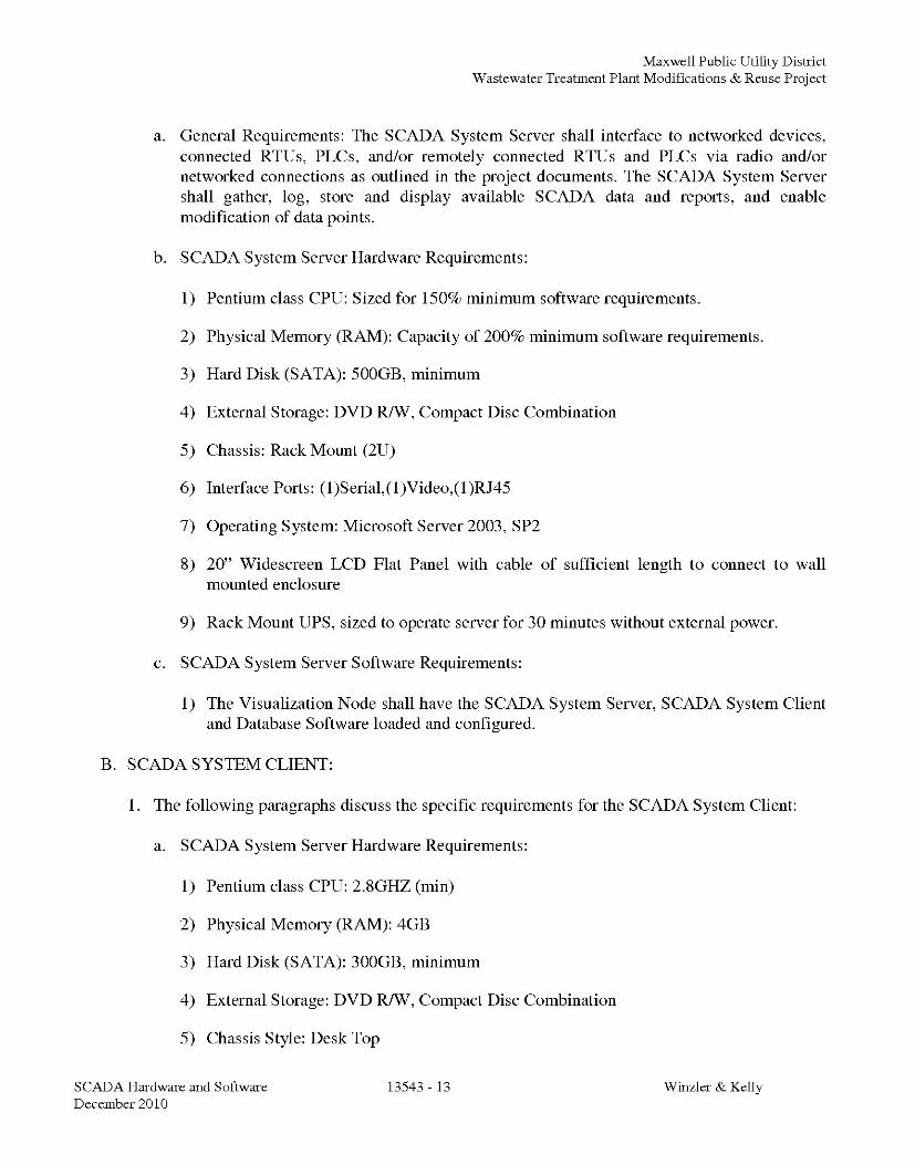
a. General Requirements: The SCADA System Server shall interface to networked devices,connected RTUs, PLCs, and/or remotely connected RTUs and PLCs via radio and/ornetworked connections as outlined in the project documents. The SCADA System Servershall gather, log, store and display available SCADA data and reports, and enablemodification of data points.
b. SCADA System Server Hardware Requirements:
1) Pentium class CPU: Sized for 150% minimum software requirements.
2) Physical Memory (RAM): Capacity of 200% minimum software requirements.
3) Hard Disk (SATA): 500GB, minimum
4) External Storage: DVD R/W, Compact Disc Combination
5) Chassis: Rack Mount (2U)
6) Interface Ports: (1)Serial,(1)Video,(1)RJ45
7) Operating System: Microsoft Server 2003, SP2
8) 20" Widescreen LCD Flat Panel with cable of sufficient length to connect to wallmounted enclosure
9) Rack Mount UPS, sized to operate server for 30 minutes without external power.
c. SCADA System Server Software Requirements:
1) The Visualization Node shall have the SCADA System Server, SCADA System Clientand Database Software loaded and configured.
B. SCADA SYSTEM CLIENT:
1. The following paragraphs discuss the specific requirements for the SCADA System Client:
a. SCADA System Server Hardware Requirements:
1) Pentium class CPU: 2.8GHZ (min)
2) Physical Memory (RAM): 4GB
3) Hard Disk (SATA): 300GB, minimum
4) External Storage: DVD R/W, Compact Disc Combination
5) Chassis Style: Desk Top
SCADA Hardware and Software 13543 - 13 Wirzler & KellyDecember 2010

Maxwell Public Utility DistrictWastewater Treatment Plant Modifications & Reuse Project
6) Interface Ports: (1)Serial,(1)Video,(1)RJ45
7) Operating System: Microsoft XP, SP2
8) 20" Widescreen LCD Flat Panel with cable
b. General Requirements: The SCADA System Client shall interface to networked devices,connected RTUs, PLCs, and/or remotely connected RTUs and PLCs via radio and/ornetworked connections as outlined in the project documents. The SCADA System Clientshall gather and display available SCADA data and reports, and enable modification oflocal data points.
c. SCADA System Client Software Requirements:
1) The HMI shall have the SCADA System Client Software loaded and configured.
C. SWITCHES:
1. The following paragraphs discuss the specific requirements for Ethernet based SCADAcommunications:
a. The system shall utilize switches for network control. Hubs shall not be accepted. At aminimum, each control panel shall be provided with a switch with ports equal to thedevices connected.
b. Basis of Design: N-TRON 9000 Series.
c. General:
1) Copper Cable Ports shall be as specified below unless otherwise noted:
a) 10 BASE-T/100 BASE-T communications.
d. Shielded Twisted Pair Category 6 cable
1) Maximum total cable length: 100 meters.
2. Unmanaged Switch:
a. 24 VDC SELV suitable for P1 and P2 redundant power supplies.
b. Minimum 0-60 degree C. operating temperature.
c. Multimode or single mode optical fiber.
d. Switches shall be configured for project conditions. If a switch is not available with theproper configuration, then switch cascading shall be permitted.
SCADA Hardware and Software 13543 - 14 Wirzler & KellyDecember 2010

Maxwell Public Utility DistrictWastewater Treatment Plant Modifications & Reuse Project
D. UNINTERRUPTIBLE POWER SUPPLIES:
1. Uninterruptible Power Supplies (UPS) shall be provided for the SCADA System Server,HMIs, PLCs and switches. As a general rule, provide a dedicated UPS for each cabinet andeach major SCADA component location. Sharing of UPS's is allowed as long as a single pointof UPS failure cannot disable the system. The UPS system shall be able to run on Utility orgenerator power without any disruption in service. UPS's will be sized according to thefollowing:
a. 89 to 151 VAC Input with automatic 50/60 Hz detection, 127 joules total energydissipation surge suppression, data line protection, and user resettable circuit breaker.
b. Continuous battery recharging, even if the power button is set to OFF. The UPS shall havea battery replacement indicator, and shall allow batteries to be replaced via the front panel.
c. The UPS shall have a minimum of 4 NEMA 5-15R plugs.
d. The UPS shall be approved by UL, and cUL. The UPS shall carry the CE logo, and shallcomply with EN 50 091, and IEC 62 040.
e. The UPS shall have a set of discreet contacts for connection to the PLC. The UPS shallhave a power management software package suitable for Windows.
f. Basis of design: Basis of design will be the MGE UPS Systems Nova AVR by SchneiderElectric.
g. Run time shall be based on a 45 minute outage with alarm contact closure for low batteryand general alarm.
1.07 SCADA SOFTWARE
A. GENERAL
1. Description: The SCADA software package shall be part of a complete SCADA system. Thissystem shall include all required networked hardware.
2. Core SCADA Functionality: All core SCADA functionality offered, such as communicationsdrivers, graphics capabilities, reporting, historical storage, trend and alarm displays and thedevelopment environment are offered as a single integrated software package or suite ofpackages. The software shall be designed with the ability to make changes to the graphicswhile the system is running. Shutting down the system for graphic changes is not acceptable.
3. Additionally, software will be supplied to augment, or replace functionality of the softwarepackage:
a. Additional Operator and HMI Pages including; Graphics, I/O representation and reportgeneration.
SCADA Hardware and Software 13543 - 15 Wirzler & KellyDecember 2010

Maxwell Public Utility DistrictWastewater Treatment Plant Modifications & Reuse Project
b. SMS software for remote annunciation of alarms.
c. Email software for emailing of alarms.
4. Application size: The SCADA software and engineering configuration shall be based on thetotal number of device points being measured and derived plus a 20% spare capacity.
5. Customized Application Programming: Additional SCADA software programming shallinclude:
a. Configured Graphics Pages: The Owner shall be provided with 8 graphics pages to be usedat the SCADA System Server and SCADA System client to access devices.
b. Alarms: The Owner shall be provided with device level alarming for each connecteddevice and 4 customized general alarm pages to be used at the SCADA System Server andSCADA System client to access devices.
c. Trends: The project shall be provided with customizable trends tables indicating trends bydevice. Values shall be scaled per device and quantity measured.
d. Historical Reporting: The Owner shall be provided with customizable reports historicalreports for each device connected indicating trend values, min/max values, totals anddevice specific information.
e. Development: The Contractor shall coordinate with the Owner for specific designrequirements prior to commencing work. The SCADA Contractor shall provide a 50% and100% design meeting after initial coordination meeting with Owner. Final 100% designmeeting shall occur within 60 calendar days of successful review of HMI and PLCsubmittals.
B. CONNECTIVITY:
1. Description: The SCADA software shall employ an I/O client to manage the reading andwriting of data from PLCs, RTUs, and system components. The 110 client shall provide thedata on request to any SCADA System Client in the network.
C. COMMUNICATIONS
1. Description: The SCADA software shall be capable of communicating to PLCs connected tothe network, remote PLCs, 110 clients, and other devices on the network.
2. Communication failure at any node shall not render that node or any attached nodesinoperable. Each node shall function independently using a locally stored program.
3. General communication capabilities. The SCADA software shall have the followingcommunications capabilities:
SCADA Hardware and Software 13543 - 16 Wirzler & KellyDecember 2010
Maxwell Public Utility DistrictWastewater Treatment Plant Modifications & Reuse Project
a. Support for redundant communication paths to field controllers, and provision forautomatic changeover to the standby path in the event of a communications failure.
b. Built in diagnostic alarms shall be provided with the system that will automatically notifythe operator of the failure of any communications path both locally and remotely.
c. A package of communication drivers that shall include the following as a minimum:
1) Modbus Driver
2) Ethernet/IP Driver
4. Communication re-establishment:
a. Upon re-establishment of communications after a failure all historical alarm, event andtrend data archived by the remote field device (RTU) shall be automatically backfilled intothe SCADA System Server and Client alarm and trend history files.
D. SECURITY
1. Description: Security features shall be fully integrated to allow only users with appropriatesecurity levels access to individual parts of the system.
2. Security Capabilities: The SCADA software shall have the following:
a. Encrypted passwords that are verified at each node and at the server side.
b. Passwords shall be hidden in both the configuration and runtime environments to ensurethat personnel cannot access another account without authorization.
c. Monitoring and logging of each Operator Interface and of each user. This shall include alloperator control actions where inputs or outputs are forced, modifications are made andsystem log in and log out with time and date stamps. The sequence of actions shall beviewable within the SCADA package and also stored in an external open file format (e.g.txt, csv, dbf, sql) for later analysis.
d. Automatically log out a user after an adjustable time period. Logging out a user will onlycause the system to revert to a view only security status. Logging out will not shutdownany node or interface.
e. A minimum of 6 privilege levels shall be available for each user. The software shall ensurethat a user has access to all tasks for his privilege level. If the user does not have thecorrect privilege for a task a message will indicate insufficient privilege and log theattempt at the SCADA System Server.
SCADA Hardware and Software 13543 - 17 Wirzler & KellyDecember 2010

Maxwell Public Utility DistrictWastewater Treatment Plant Modifications & Reuse Project
f. Assign each graphic object at each plant area, define the privilege level, define whetheroperator input is enabled or disabled, and if the object will be visible or not based on theoperator's current privilege levels within the plant area.
g. A mechanism to restrict access to different areas of the plant for each individual user orgroup of users.
E. GRAPHICAL DISPLAYS
1. Description: Graphical displays are windows that are used to represent part or all of a processin a graphical manner.
2. General Graphical Display Capabilities: The SCADA software shall have the followinggraphical display features:
a. Unlimited number of graphical displays.
b. Capable of a minimum of 2000 analog variables, with real time updates of less than 500ms(for all data to appear or change on the page)
c. Capable of automatically re-sizing to match the screen resolution of the computer on thenetwork, irrespective of the resolution the pages were developed in or configured for, andirrespective of whether vector or bitmap graphics are used on the page, without shuttingdown the SCADA software, without recompiling, and without having multiple copies ofgraphic pages for different resolutions.
d. Support a screen resolution of up to 1280 x 1280 pixels.
e. Support full 32 bit graphics, and capable of displaying images from third party packagesfor use within the SCADA displays, including animating and vector graphic images.
f. Capable of pop-up windows for trends, loops, device status, and device control by clickingon hot spots or objects on the main graphics page. Simultaneous opened popup displaywindows shall be supported by the graphics display system.
g. Inclusion of page name, current time and date together with details of the last 6 alarms thathave occurred on all graphical displays.
h. Ability to allow the user to navigate around the graphics system utilizing a variety ofnavigation methods.
i. Ability to have Hot Key links to specific graphics pages from the keyboard.
j. Windows style navigation menus allowing access to any configured page in the systemfrom any other page.
k. Configured with "hot spots", where as a user can click on the area and drill down into adetailed view (if available) of the plant area.
SCADA Hardware and Software 13543 - 18 Wirzler & KellyDecember 2010

Maxwell Public Utility DistrictWastewater Treatment Plant Modifications & Reuse Project
1. Ability to display communication loss for a particular I/O point wherever that data isdisplayed in the software.
m. Touch screen friendly icons for HMIs employing touch screen capabilities. The area to be'clicked' shall be large enough for a standard finger and designed to prevent accidental'clicking' of adjacent areas.
3. Dynamic Objects: Dynamic objects are symbols that visually change when a property, tag orexpression changes. Dynamic objects shall include:
a. Support the following graphical dynamic objects as a minimum:
1) freehand lines
2) straight lines
3) poly-lines
4) rectangles (including the latest curved corner style)
5) ellipses
6) pie slices
7) text
8) buttons (of the latest WinXP style)
9) Bitmaps
4. Dynamic objects shall have a series of properties that can be used independently orconcurrently. Each dynamic object shall have the following properties:
a. Horizontal, Vertical and Rotational movement
b. Up, Down, Left or Right Level Fill
c. Gradient Level Fill
d. On-Off, Multi-State, Integer, Threshold or Gradient Color Change
e. Horizontal and Vertical Size
f. Visibility
g. Keyboard Input
h. Touch (Mouse Up, Down, While Down) input
SCADA Hardware and Software 13543 - 19 Wirzler & KellyDecember 2010

Maxwell Public Utility DistrictWastewater Treatment Plant Modifications & Reuse Project
i. Horizontal and Vertical or Rotational Slider
j. Ability to disable the object based on security levels.
k. Popup information in a "tool tip" form by rolling the mouse over the object
5. ActiveX: The SCADA software will be an ActiveX container and allow for insertion ofActiveX objects into standard graphics pages. ActiveX components include Adobe Flash,JavaScript enabled routines, etc. The SCADA software shall interact with ActiveX objects inthe following ways:
a. Dynamically change properties of an ActiveX object via a Tag from an I/O Device
b. Dynamically change properties from SCADA software high level language.
c. ActiveX object to trigger actions in the SCADA software based on events in the ActiveXObject.
d. ActiveX property values can be read by the SCADA software.
F. ALARMS
1. Description: Alarms are meant to alert and operator of an abnormal condition. They arelogged, and require operator intervention.
2. General Alarm functionality: The alarm functionality shall have the following:
a. No software limit on the number of alarms supported
b. Acknowledgement on one operator interface terminal shall be globally acknowledged andas such shown as Acknowledged on all operator interface terminal s. This shall beconfigured as one common database, with no other programming necessary to enableglobal acknowledgment of alarms from any node in the network.
c. Alarm pop up displays shall expire upon alarm event being cleared at any of the nodeswithin the network.
3. Alarm Types: The SCADA software shall monitor analog and discrete variables and calculatedconditions, and determine if the variable is in an alarm condition. The SCADA software shallperform the following:
a. All analog alarm conditions shall have adjustable dead bands and delay timers to minimizenuisance alarms. All analog alarm properties shall be adjustable without the need to shutthe system down. For each Analog Tag, an alarm for each of the following conditions shallbe assignable:
1) LOW,
SCADA Hardware and Software 13543 - 20 Winzler & KellyDecember 2010

Maxwell Public Utility DistrictWastewater Treatment Plant Modifications & Reuse Project
2) HI,
3) Deviation LO
4) Deviation HI
5) Rate of Change
6) Device Fail
7) Device Level Assignable Alarm
8) Communications Loss
b. Discrete alarms shall have an assignable alarm for each of the following:
1) Variable ON
2) Variable OFF
c. Multi-Digital Alarms based on a combination of discrete tags. Any combination of statesof the discrete tags may be configured to be an alarm. Furthermore, a new alarm signalshall be initiated whenever a new alarm state is encountered.
d. All alarm processing shall use time and date stamping based on origin of alarm andclearing of alarm.
4. Alarm Display: Alarm display shall have the following:
a. Depending on user's log-in privileges, it shall be possible to display or acknowledge anyalarm and/or the most recent alarm on any page.
b. Alarm shall be configurable in multiple levels. The color of the text of the alarm messageshall indicate priority. Text color shall be determined in initial design review meeting.
c. Sound indication for each alarm category shall be configurable. This must be possible ateach node via internal or external speaker. The sound indication shall support the playingof any standard .WAV and .MP3 file.
d. Provided with a standard alarm user modifiable display page. The alarm page shall allowfor scrolling of alarms, and acknowledgment of individual alarms or all alarms on thepage.
e. Possibility to display the following information for each alarm as it appears on an alarmdisplay page:
1) Alarm Tag Name
SCADA Hardware and Software 13543 - 21 Wirzler & KellyDecember 2010

Maxwell Public Utility DistrictWastewater Treatment Plant Modifications & Reuse Project
2) Alarm Description
3) Value of the Variable
4) Alarm Status - Disabled, Acknowledged, Unacknowledged
5) Alarm Category or Priority
6) Time & Date
7) Value of associated tags, devices or results of associated calculations.
8) User comments, where alarm is to be locked out by authorized user.
f. Based on user's privileges, it shall be possible to disable alarms on individual basis, bypage or by alarm category or all alarms. A disabled alarm page shall indicate to every userwhich alarms have been disabled and which user disabled the alarm with user incorporatedcomments, including area for description of lockout purpose.
g. Based on user's privileges, it shall be possible for user comments to be attached to anyalarm. These comments shall either be displayed with the alarm or by clicking on thealarm.
h. Possibility to automatically display any graphic display when an alarm occurs or todynamically change the appearance of any graphical object based on whether an alarm isOn, Off, Acknowledged, Communications Error or Disabled.
i. A mechanism for operators to dynamically define filtering of alarms by alarm name, tagname, date/time range, state or type.
5. Alarm Logging: The following alarm functionality shall be provided:
a. Alarms that are logged to disk shall be viewable while the system is online or offlinewithout interrupting data collection. The software shall not limit the number of alarmslogged to disk. The alarm logging shall be capable of logging an instantaneous burst ofalarms without losing any single alarm notification.
G. TRENDS
1. Description: Trends are a collection of data points over time. When viewed over time, thetrends will indicate general progression of the data.
2. General Trend Functionality: The software shall have the following functionality.
a. The number of trends collected shall not be limited by the software.
b. The software shall be capable of logging historical trend information at configurablesample periods from 1 Millisecond to 24 Hours.
SCADA Hardware and Software 13543 - 22 Wirzler & KellyDecember 2010

Maxwell Public Utility DistrictWastewater Treatment Plant Modifications & Reuse Project
c. Trend data shall be stored in a file system with the sample period, file location, privilege,owner and area being user definable individually for each trend. File names and paths shallsupport file names up to 255 characters in length.
d. Every tag defined in the system configuration shall be trended. Each trend shall contain aminimum of 2 years historical data at a 10 minute sample rate. The trends shall bemaintained online for operator call back without the need to backup or restore history files.
3. Trend Display: The software shall have the following in its native functionality:
a. Each operator and login shall be able to view fully customized trend pages. These pagesshall be customizable on line by each user in a drop down menu fashion. Any settingavailable to be made in a configuration environment shall be available to the user tomodify the trend graphs in run time. These include the color, scaling, pen selection asexamples.
b. Line graphs with time on a linear, continuous horizontal or vertical axis and the trendedvariable on the vertical or horizontal axis. Resolution of each graph shall be to within 0.1%of full scale.
c. Where more than one variable is displayed on the same graph, the pen color of eachvariable and associated information shall be displayed in a different color.
d. Each trend graph shall be capable of displaying a minimum of 12 trend pens withadjustable time base to one second samples and shall be capable of viewing the entirearchived trend history.
e. Each pen shall display individual ranges and engineering units. Each pen shall be scalablefor display purposes independent to each other pen displayed on a page.
f. Include the capability to pan backward and forward within a selected time range to read theexact value of any displayed variable, by selecting a point on the graph or chart. Thesystem shall display historical information as far back in time as desired, with allinformation being displayed within 1 second.
g. The software shall provide "zoom" and "pan" facilities for both the trended variable rangeand the time axis range. The "zoom" facility shall allow an operator to compress or expandthe axis range whilst the "pan" facility shall allow an operator to shift the origin of the axis.The software shall allow a user to define any zoom area by dragging a mouse across thetrend.
h. The software shall make available trending data from a historical database for export todisk files or external databases. It shall be possible to define the section of the trend to beexported by clicking and dragging the mouse across the trend. Data shall be portable tocsv, dbf or txt formatted files. It shall also be possible to export any portion of thehistorical trend database via ODBC, DDE, dbf, CSV and TXT formats.
H. DEVELOPMENT ENVIRONMENT
SCADA Hardware and Software 13543 - 23 Wirzler & KellyDecember 2010
Maxwell Public Utility DistrictWastewater Treatment Plant Modifications & Reuse Project
1. Description: The development environment is the area that allows generation of graphicscreens, alarms screens, tag database, trend screens etc.
2. General Development Environment Functionality: The SCADA software shall include adevelopment environment with the following:
a. An integrated development package utilizing menu driven, fill in forms style configurationto develop the runtime system.
b. All development functions shall be available at the SCADA System Server node.
c. A utility to back-up or restore an entire database including all graphic displays,configuration data and source code, as well as online configuration (such as menunavigation, trend groups and alarm groups), via a simple point and click method shall beprovided. The backup/restore utility shall prompt the user prior to over writing any existingfiles. The utility shall employ automatic file compression and decompression.
d. Ability to import field controller tag definitions shall be included as a standard feature.Automatic updating upon a change of a definition in the 110 device tag names, addresses,ranges etc will automatically be imported into the SCADA software database. In addition itshall be possible to manually initiate the import of tag definitions at any time. The Tagimport function shall be user configurable such that a user can specifically define whichdefinition fields must not be overwritten or define how the import will operate. The importfunction shall support generic OPC data sources and CSV file imports in conjunction tonative field controller programming software database imports.
I. GRAPHIC BUILDER
1. Description: The graphic builder allows for development of graphic screens.
2. General Graphic Builder functionality: The graphics builder shall be interactive and menu-driven, requiring no programming. It shall consist of the following:
a. Directly import graphics and text in the following file formats:
1) AutoCAD DXF
2) Windows BMP
3) Windows Meta File WMF
4) JPG
5) GIF
6) TIF
SCADA Hardware and Software 13543 - 24 Winzler & KellyDecember 2010
Maxwell Public Utility DistrictWastewater Treatment Plant Modifications & Reuse Project
b. The graphics builder shall be capable of creating screens composed of both static anddynamic objects. To create these objects, the software shall provide sample screens and aset of standard shapes in a library. The developer shall be able to include these symbols byreference, or create new symbols/objects.
3. ActiveX: The graphics builder shall have an assignable ActiveX container. ActiveX objectsshall be capable of being inserted and edited in a visually interactive manner. It shall bepossible to connect ActiveX properties to tags, allowing read/write between properties andtags without the need for script or code. ActiveX objects must have the same security as nativegraphics objects and ActiveX objects shall be visible or hidden based on the users' privilegelevel.
J. CUSTOM SCRIPTING LANGUAGE
1. Description: The scripting language shall be used to develop custom routines, and algorithmsnot supplied as part of the standard package.
2. General Custom Scripting Functionality: The SCADA software's scripting functionality shallinclude the following.
a. An integrated high level language specifically designed for SCADA applications that shallbe inherently multi-tasking and multi-threading.
b. Fully integrated and multi-threaded Visual Basic (VB) scripting.
c. Access to all field tags, alarms, graphics displays, database and ASCII files. The languagesshall include functions with clear and precise syntax. The languages shall support userwritten functions and function libraries supported by the computer's operating system. Thelanguage shall have the capability to export or import data from other applications.
d. Creation of calculated (inferred) variables based upon formulae including constants,measured variables and other calculated variables. All facilities available for logging,reporting, trending, monitoring, controlling, alarming and displaying measured variablesshall also be available for calculated variables.
3. Support of mathematical and Boolean operators.
4. Support for mathematical functions.
5. Prevention of any functions from interfering with proper SCADA functionality.
6. Permit users to create their own functions and integrate them. All functions shall be reusable.It shall be possible to call the same function multiple times from different locations, withdifferent parameters simultaneously.
SCADA Hardware and Software 13543 - 25 Wirzler & KellyDecember 2010

Maxwell Public Utility DistrictWastewater Treatment Plant Modifications & Reuse Project
7. Provisions to run functions automatically on start up, on page entry, on page exit, while a pageis open, on button down, while button down, embedded in reports, alarm on, alarm off, on anykeystroke, any keyboard entry on any mouse button click, etc.
1.08 QUALITY ASSURANCE
A. Installer Qualifications:
1. A qualified installer shall have, within 200 miles of Project site; a facility, capable ofproviding parts, service and coordination of emergency maintenance and repairs.
B. Source Limitations:
1. All SCADA HMI Software shall be from a single manufacturer.
C. Electrical Components, Devices, and Accessories:
1. Listed and labeled as defined in NFPA 70, Article 100, by a testing agency acceptable toauthorities having jurisdiction, and marked for intended use.
D. Comply with NFPA 70.
E. SCADA System Availability Requirements:
1. A fundamental objective of the SCADA System Supplier's proposed system design shall be toensure that no single equipment failure or temporary error condition can disable the systemsoverall operation or generate any spurious control commands to the system equipment. Thisrequirement is not intended to specify a hot backup installation, but to provide a modularsystem that when a site is in error or has failed; will not disrupt the whole of the SCADAsystem or prevent another site or terminal at another site within the SCADA system fromfunctioning as designed.
F. Single Point of Failure:
1. The SCADA equipment configuration shall prevent any single hardware or software failurefrom causing loss of any system function or from causing overall system malfunction. Singlehardware failures may cause loss of specific communication channels temporarily until failedequipment is replaced. This requirement is not intended to specify a hot backup installation,but to provide a modular system that when a component is in error or has failed; will notdisrupt the whole of the SCADA system or prevent the site from functioning as designed inmanual mode.
G. SCADA Operational Checks:
1. The SCADA System Supplier's proposed system shall continually poll each component in thesystem for operation, alarm 1/0, and report the malfunction. Upon detecting a malfunction, thefailed operation shall be attempted a number of times (programmable) in order to determine
SCADA Hardware and Software 13543 - 26 Wirzler & KellyDecember 2010

Maxwell Public Utility DistrictWastewater Treatment Plant Modifications & Reuse Project
whether the malfunction is temporary or permanent. Permanent malfunctions shall be alarmedand logged. Temporary malfunctions shall be logged for maintenance purposes.Communication delays shall not be logged as a device specific alarm.
H. System Availability:
1. During the System Availability Demonstration, the SCADA system shall achieve an averageavailability rate for all functions of at least 99.95 percent. This is equivalent to a totaldowntime of approximately 4 hours per year for the System. The system AvailabilityDemonstration shall be part of the warranty guarantee.
1.09 DELIVERY, STORAGE, AND HANDLING
A. Store SCADA software in a secured location and in binders. As a minimum, store indoors inclean, dry space with uniform temperature to prevent condensation. Protect SCADA software fromtheft, loss, exposure to dirt, fumes, water, corrosive substances and physical damage. TheContractor shall retain responsibility to deliver all documents and hardware to the Owner as partof the project close-out procedures.
1.10 WARRANTY:
A. System Warranty Overview:
1. The system warranty shall consist of a full scope, in-place warranty, consistent with theprovisions of the Terms and Conditions in the project documents. The warranty duration shallbe 36 months. All hardware components and system programming that is a part of thecompleted system shall be covered by the warranty. The Contractor shall not provide thirdparty warranties.
PART 2- PRODUCTS
2.01 MANUFACTURERS
A. Software Manufacturer: Subject to compliance with requirements, manufacturers offering productsthat may be incorporated into the Work include, but not limited to:
1. Invensys Wonderware InTouch
2. Invensys Wonderware Historian
3. Invensys Wonderware SCADAlarm
4. Invensys Wonderware Information Server
B. PLC Programming Software:
1. PLC programming software compatible with installed system.
SCADA Hardware and Software 13543 - 27 Wirzler & KellyDecember 2010

Maxwell Public Utility DistrictWastewater Treatment Plant Modifications & Reuse Project
a. Provide 1 License, program for use with Microsoft Windows XP/Vista operating systemand related cables required to connect to PLC. Coordinate with Owner for systeminstallation and configuration requirements.
PART 3- EXECUTION
3.01 EXAMINATION
A. Examine areas, surfaces, and substrates to receive SCADA System and associated control panelsfor compliance with requirements, installation tolerances and other conditions affectingperformance.
B. Proceed with installation only after unsatisfactory conditions have been corrected.
3.02 APPLICATIONS
A. Select SCADA Software based on application type, tag count, type of node. It is recommendedthat a manufacturer's representative be consulted during the selection.
3.03 INSTALLATION
A. Fasten control panels, and other devices.
B. Ventilation slots shall not be blocked, or obstructed by any means.
3.04 IDENTIFICATION
A. Identify components, and wiring according to all applicable codes, standards and contractdocument sections.
3.05 FIELD QUALITY CONTROL
A. Field Service:
1. The Contractor shall provide a qualified service representative to perform the following:
a. Inspect wiring, components, connections and equipment installation for conformance.
b. Test and calibrate instrumentation and equipment.
c. Provide software programming, loading and debugging.
d. Install and test SCADA applications.
e. Report results in writing.
B. Installation and Start-Up:
SCADA Hardware and Software 13543 - 28 Wirzler & KellyDecember 2010

Maxwell Public Utility DistrictWastewater Treatment Plant Modifications & Reuse Project
1. Develop a specific plan for the startup and commissioning of the SCADA system and for anyrequired cutover. No startup or cutover activities shall be performed until the plan has beensuccessfully approved by the Owner and Engineer.
C. Site Acceptance Test:
1. A Site Demonstration Test of the functions, software, and performance shall be conductedafter all system elements have been installed and the I/O point checkout has been completed.The system site demonstration tests shall be performed to verify complete operation of thesystem, requiring a repeat of much of the comprehensive system tests but with the equipmentinstalled at the permanent sites, and shall include additional tests required to verify fieldinstalled equipment. The 110 point checkout shall include, but not be limited to:
a. Verify all the facility installations.
b. Demonstrate each functional requirement identified by the specification.
c. Demonstrate all equipment control functions, including the operation of automatic controlstrategies. Actuation of field devices shall be closely coordinated with facility operations.
d. Verify system performance parameters and system responses under field operationalconditions.
e. Verify accuracy of documentation, especially operator's manuals, software documentation,and general system operating instructions.
2. Provide the appropriate technical representatives for the execution of the Site DemonstrationTest. Test support personnel shall be qualified to resolve and correct problems encounteredwith the system during the tests. In addition to test support personnel, provide all testinstruments and equipment necessary to troubleshoot any of the proposed system problemsencountered. The Owner reserves the right to increase the requirements for test supportpersonnel if support is inadequate.
D. Demonstration
1. Provide a qualified service representative to train Owner personnel to adjust, operate, andmaintain SCADA system as detailed below.
2. Site Availability Demonstration:
a. Test Requirements:
1) At the completion of Site Acceptance Test (SAT), the Integrator shall conduct a SiteAvailability Demonstration test utilizing all equipment, software, and services providedunder this Contract. During the test the system shall meet the availability criteriadefined below and shall meet the performance requirements stated in the specification.Owner personnel may elect participate in any and all parts of this demonstration asobservers at the discretion of Owner.
SCADA Hardware and Software 13543 - 29 Wirzler & KellyDecember 2010

Maxwell Public Utility DistrictWastewater Treatment Plant Modifications & Reuse Project
b. Scope of Test:
1) All equipment and software delivered with the system shall be subject to theavailability measurements.
c. Test Equipment:
1) The Site Availability Demonstration shall be performed under field operatingconditions. All functional and performance requirements specified in this documentshall be met during the SAT.
d. Length of Test:
1) The system shall be subjected to Site Availability Demonstration evaluation for aperiod of not less than 60 days (1440 hours). If at the end of the 60 days, the systemavailability is determined to be less than that required, the test shall continue on a day-by-day basis, dropping off the oldest day's test results. This sliding window conceptshall continue until the system passes the test or until 120 days time has passed.
e. Preventive Maintenance:
1) During the Site Availability Demonstration period, perform preventive maintenance ofthe type and the frequency of service defined in the SCADA maintenance manuals.Supply a recommended maintenance plan prior to start of the test.
f. Test Prerequisites:
1) Prerequisites to starting the SAT are successful completion of the ComprehensiveSystem Test and the Site Demonstration Test and resolution of all outstandingDiscrepancy Reports.
a) Final copies of O&M manualsb) Final copies of System Operator's manualsc) Final copies of System Administrator manualsd) Final Record Documents.
g. Progress Reports:
1) Maintain the official record of operating time, recorded incidents and disposition,maintenance action, and calculated availability. At the completion of systemavailability demonstration, prepare a separately bound test report for Engineer toevaluate and approve.
h. Letter of System Acceptance:
SCADA Hardware and Software 13543 - 30 Winzler & KellyDecember 2010

Maxwell Public Utility DistrictWastewater Treatment Plant Modifications & Reuse Project
1) Upon review and approval of SAT, the Owner shall provide a letter documenting thatthe SAT has been completed.
E. Training:
1. Training Overview:
a. Provide A comprehensive training program covering the operation and maintenance of allelements of the proposed system.
b. For training sessions conducted on-site, the Owner will provide the necessaryworkstations.
c. All training classes shall be completed prior to the start of the Site Acceptance Test.
d. Training shall not be combined with other activities such as system configuration orstartup.
2. Required Training Sessions:
a. Sufficient sessions shall be presented to satisfy session size restrictions and conflicts infacility personnel scheduling. If the standard training curriculum includes applicableinformation in addition to those discussed below, the Contractor shall also provide thesecourses. The categories of training to be provided shall be:
1) Operator Training:
a) Training sessions shall be presented that instruct the system operators in theefficient operation of all aspects of the SCADA. The course material shall includethe general operation of the SCADA system, and the operation of the specificsystem features incorporated in the SCADA system. In particular, the operatortraining shall include instruction on the use of all operational functionality.
2) Software Maintenance Training:
a) Training sessions shall be presented that will enable facilities staff to develop andmaintain all aspects of the system software. Separate sessions shall be presentedthat deal with the following topics:
1. Process database replication, backup and restoration
2. Process display development and modification
3. Supervisory Control strategy development and modification
4. Report development and modification
SCADA Hardware and Software 13543 -31 Wirzler & KellyDecember 2010

Maxwell Public Utility DistrictWastewater Treatment Plant Modifications & Reuse Project
5. General software maintenance, including system backup, restoration andarchiving.
6. Calculation additions, alarm and event logging additions, Graphic display,report and trend additions
7. Network training for adding additional equipment (printers, workstations, etc)or additional PLCs / RTUs and I/O from the SCADA Network
8. Adding, editing, transporting and testing of data sent to historical databasesystem
9. Any Third party tools for accessing data from any database.
3. Training sessions shall address the procedures for the standard SCADA system software, plusmaterial explaining the specific conventions and procedures used by the Contractor indeveloping the SCADA applications. The sessions shall also provide instruction in techniquesfor developing and maintaining current, comprehensive documentation for all applications.
END OF SECTION
SCADA Hardware and Software 13543 - 32 Wirzler & KellyDecember 2010