Parker Vent Master™ - iTEMS™ · Parker Vent Master™ Process Analyzer Vent-Header Pressure...
20
Parker Vent Master™ Process Analyzer Vent-Header Pressure Control System Catalog 4142-VM February 2014
Transcript of Parker Vent Master™ - iTEMS™ · Parker Vent Master™ Process Analyzer Vent-Header Pressure...

Parker Vent Master™Process Analyzer Vent-Header Pressure Control SystemCatalog 4142-VM February 2014

ii Parker Hannifin CorporationInstrumentation Products DivisionJacksonville, AL USAhttp://www.parker.com/ipdus
Catalog 4142-VM

1 Parker Hannifin CorporationInstrumentation Products DivisionJacksonville, AL USAhttp://www.parker.com/ipdus
Catalog 4142-VM Table of Contents
© Copyright 2014 Parker Hannifin Corporation. All Rights Reserved.
Description .........................................................................................................Page
Parker Vent Master™
Introduction ...........................................................................................................2
Functional Options ................................................................................................3
Parker Vent Master™ Eductor (-EDR) Model Theory of Operation ........................4-5
Eductor Motive Force / Return Point Back Pressure / Flow Curves .....................6
Nitrogen (-EDR) Model Installation and Startup Procedures ................................7
Eductor Natural Gas (-EDRNB) Model Installation and Startup Procedures ........8
Parker Vent Master™ Pump (-PMP) Model Theory of Operation ............................19
Pump Model Installation and Startup Procedures ..............................................10
Parker Vent Master™ No Pump or Eductor (-NPE) Model Theory of Operation .....11
No Pump or Eductor Model Installation and Startup Procedures .......................12
Dimensions ..............................................................................................................13
How to Order ...........................................................................................................13
Specifications ..........................................................................................................13
Conversions .............................................................................................................14
Safety & Maintenance .............................................................................................15
Offer of Sale ............................................................................................................16
Parker's Motion & Control Technologies .......................................... inside back cover
Offer of SaleThe items described in this document are hereby offered for sale by Parker-Hannifin Corporation, its subsidiaries or its authorized distributors. This offer and its acceptance are governed by the provisions stated in the detailed “Offer of Sale” elsewhere in this document or available at www.parker.com/ipdus.
WARNING – USER RESPONSIBILITYFAILURE OR IMPROPER SELECTION OR IMPROPER USE OF THE PRODUCTS DESCRIBED HEREIN OR RELATED ITEMS CAN CAUSE DEATH, PERSONAL INJURY AND PROPERTY DAMAGE.
This document and other information from Parker-Hannifin Corporation, its subsidiaries and authorized distributors provide product or system options for further investigation by users having technical expertise.
The user, through its own analysis and testing, is solely responsible for making the final selection of the system and components and assuring that all performance, endurance, maintenance, safety and warning requirements of the application are met. The user must analyze all aspects of the application, follow applicable industry standards, and follow the information concerning the product in the current product catalog and in any other materials provided from Parker or its subsidiaries or authorized distributors.
To the extent that Parker or its subsidiaries or authorized distributors provide component or system options based upon data or specifications provided by the user, the user is responsible for determining that such data and specifications are suitable and sufficient for all applications and reasonably foreseeable uses of the components or systems.

2 Parker Hannifin CorporationInstrumentation Products DivisionJacksonville, AL USAhttp://www.parker.com/ipdus
Catalog 4142-VMParker Vent Master™
Image courtesy of ABB
Introduction
After a process sample stream is analyzed, it must be disposed of in a manner consistent with environmental regulations. Today, as in the past, it has been common practice to simply vent the sample stream to the atmosphere. As environmental regulations become more stringent, it is becoming undesirable, if not illegal, to admit these samples to the atmosphere.
For an analyzer to operate correctly, it must be calibrated and operated under the same conditions. These critical conditions are temperature, flow and pressure, with the pressure of the measurement cell being the most critical. Venting analyzer effluent to atmosphere is not only convenient, but it also provides a very stable reference pressure for the analyzer measurement cell. In other words, the measurement cell “floats” on atmospheric pressure.
Analyzer outlet sample streams are traditionally collected into a closed vent header. This vent header either flows to atmosphere or back to the process. When atmospheric venting is not allowed, the most common disposal point is the plant flare where the analyte sample stream is burned. However, the flare header is subject to pressure variations as high as 20 psig or more as process upsets create backpressure. When venting an analyzer into the flare collection system, the measurement cell “floats” on these varying pressures. If this condition is left unchecked these pressure fluctuations will result in significant analyzer measurement errors.
The primary function of the Parker Vent Master™ is to isolate the analyzer from fluctuating outlet pressures by controlling the pressure of the collection header (commonly referred to as the Vent Header) and pumping the effluent sample gases into the fluctuating return system.
3 Parker Hannifin CorporationInstrumentation Products DivisionJacksonville, AL USAhttp://www.parker.com/ipdus
Catalog 4142-VM Parker Vent Master™
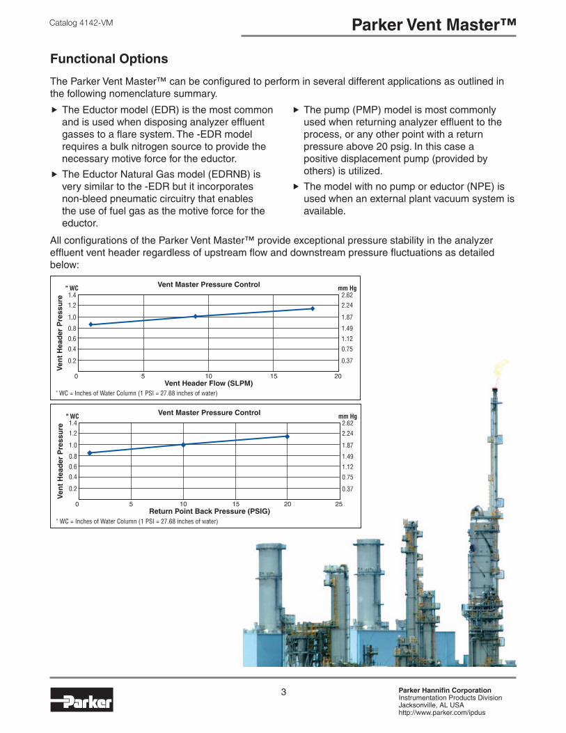
Functional Options
The Parker Vent Master™ can be configured to perform in several different applications as outlined in the following nomenclature summary.
�The Eductor model (EDR) is the most common and is used when disposing analyzer effluent gasses to a flare system. The -EDR model requires a bulk nitrogen source to provide the necessary motive force for the eductor.
�The Eductor Natural Gas model (EDRNB) is very similar to the -EDR but it incorporates non-bleed pneumatic circuitry that enables the use of fuel gas as the motive force for the eductor.
�The pump (PMP) model is most commonly used when returning analyzer effluent to the process, or any other point with a return pressure above 20 psig. In this case a positive displacement pump (provided by others) is utilized.
�The model with no pump or eductor (NPE) is used when an external plant vacuum system is available.
All configurations of the Parker Vent Master™ provide exceptional pressure stability in the analyzer effluent vent header regardless of upstream flow and downstream pressure fluctuations as detailed below:
4 Parker Hannifin CorporationInstrumentation Products DivisionJacksonville, AL USAhttp://www.parker.com/ipdus
Catalog 4142-VMParker Vent Master™
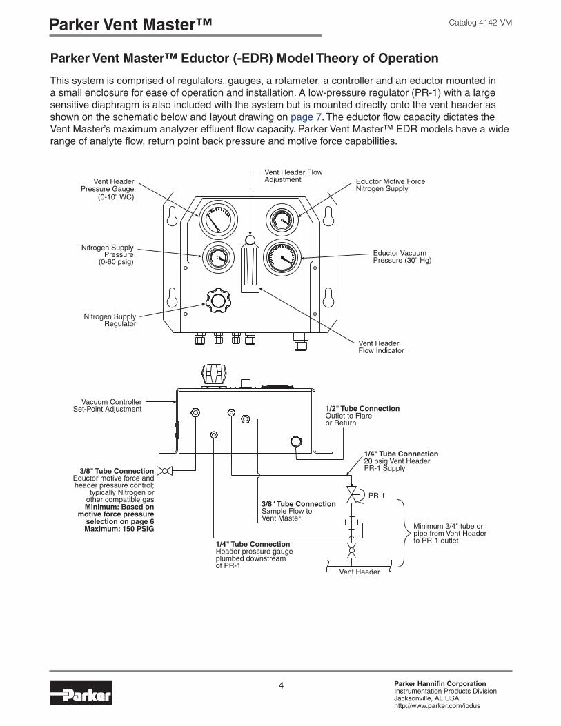
Parker Vent Master™ Eductor (-EDR) Model Theory of Operation
This system is comprised of regulators, gauges, a rotameter, a controller and an eductor mounted in a small enclosure for ease of operation and installation. A low-pressure regulator (PR-1) with a large sensitive diaphragm is also included with the system but is mounted directly onto the vent header as shown on the schematic below and layout drawing on page 7. The eductor flow capacity dictates the Vent Master’s maximum analyzer effluent flow capacity. Parker Vent Master™ EDR models have a wide range of analyte flow, return point back pressure and motive force capabilities.

5 Parker Hannifin CorporationInstrumentation Products DivisionJacksonville, AL USAhttp://www.parker.com/ipdus
Catalog 4142-VM Parker Vent Master™
PR-1 is the vent header pressure controller. Its function is to constantly flow a Nitrogen makeup gas into the vent header, sufficient to maintain a constant pressure. While each analyzer will vent effluent gas into the vent header by varying amounts, PR-1 will sense the header pressure and provide Nitrogen to makeup the difference necessary to maintain a stable +1" WC pressure. Simultaneously, the Parker Vent Master™ eductor will pump a constant analyzer effluent and Nitrogen makeup mixture from the Vent Header.
For example, if the Vent Header Flow Adjustment (FI-1) is set at 14 SLPM and the analyzers are venting a total of 12 SLPM into the vent header, PR-1 will supply 2 SLPM of Nitrogen. The flow capacity limiting component in the Parker Vent Master™ is the eductor. The Parker Vent Master™ is available with three different eductor capacities as outlined on the performance curves on page 6. In all cases, test results show that the Vent Header pressure will be maintained to within
Note: The standard PR-1 incorporates an internal relief valve on its diaphragm. The relief valve will only open when the Vent Header pressure exceeds 7" WC. The threaded vent port on the dome of the PR-1 regulator must be vented to a safe area and MUST be maintained at atmospheric pressure. ANY pressure change in the regulators dome connection will be reflected in the Vent Header. Consult factory for a PR-1 without a relief valve.
Nitrogen is the normal makeup and motive force gas used to drive the eductor because it is inert. In cases where Nitrogen is not desirable, Natural Gas can also be used to drive the eductor into a flare system or any other gas that is compatible with the process. In this case, the -EDRNB should be specified.
.3" WC pressure variation over the flow capacity range of each eductor.
The Parker Vent Master™ incorporates a Nitrogen Economizer Circuit which throttles the eductor’s motive force flow necessary to maintain a constant 6" Hg vacuum. This circuit conserves Nitrogen use and reduces the normal motive pressure eductor supply to approximately 20 psig, with an eductor return point back pressure of 1 psig. As the eductor’s back pressure increases (caused by increasing flare header pressures) the vacuum created by the eductor will be reduced. The Economizer Circuit vacuum controller monitors the eductor’s vacuum and automatically adjusts the motive force flow to the eductor accordingly to maintain a constant differential pressure necessary to facilitate a constant flow rate from the Vent Header. The motive force Nitrogen flow rate can vary from 3 to 9 SCFM depending upon the return point back pressure of the eductor as outlined in the Nitrogen Motive Force Consumption chart below.
Parker Vent Master™ Eductor Model Theory of Operation (Continued)

6 Parker Hannifin CorporationInstrumentation Products DivisionJacksonville, AL USAhttp://www.parker.com/ipdus
Catalog 4142-VMParker Vent Master™
Parker Vent Master™ Eductor Motive Force / Return Point Back Pressure / Flow Curves
The -EDR version of the Vent Master is available with three different eductor capacities. Proper eductor sizing is based on three critical system variables:�Motive force pressure availability �Maximum analyte flow from the Vent
Header�Maximum return point back pressure
Use the graphs at the right to determine the proper eductor size for an application. When the flow and return point back pressure are plotted as shown in the lines labeled “Example 1” the entire area below the plotted line must fall within the area of the line representing the available motive force pressure.
Example 1: An analyzer shelter has 8 different continuous analyzers each flowing 1 SLPM; allowing for a Nitrogen makeup cushion of 2 SLPM, the total flow is 10 SLPM. The return point is the flare header that typically runs at a pressure of 1-2 psig, but process upsets can spike this pressure as high as 22 psig. A bulk Nitrogen source with 90 psig is available for the motive force.
The red line in the graphs at right reflect the maximum flow and return point back pressure described above. In this application, the “A” eductor should be selected because it is the only graph which shows the entire dashed red line within (to the left of) the 90 psig eductor motive force value. Both the “B” and “C” eductors cannot pump against a back pressure of 22 psig at a 10 SLPM flow rate on the 90 psig motive force curve.
Example 2: A shelter’s Vent Header has a total analyte volume of 33 SLPM and the return is going back to the process that runs from 35-45 psig. In this case, none of the eductors have the capacity for the application and, the Parker Vent Master™ would be configured for a mechanical pump.
Note: Eductor “C” has a maximum return point back pressure capability of 17 psig.

7 Parker Hannifin CorporationInstrumentation Products DivisionJacksonville, AL USAhttp://www.parker.com/ipdus
Catalog 4142-VM Parker Vent Master™
Parker Vent Master™ Nitrogen (-EDR) Model Installation and Startup Procedures 1. Ensure that all connections are made as
per the drawing below. It is very important to maintain a minimum pressure drop from the Vent Header to the outlet of PR-1. A straight run of 3/4" tube or pipe is recommended.
2. Close V-1.
3. Ensure that the eductor outlet to the flare is not blocked. Blocking this flow will cause PR-1 to relieve to its vent and could cause damage to the system.
4. Open V-2 to initiate Nitrogen flow.
5. Adjust PR-2 to read 20 psig on PI-1.
6. PI-4 should read 6" Hg vacuum. If adjustment is required, remove the small cover on the upper left side of the case (X marks the spot below) with a 1/8" Allen Wrench, then adjust the set point until the vacuum is reading 6" Hg vacuum. Reinstall the cover.
7. Adjust the FI-1 rotameter needle valve to at least 2 SLPM higher than the MAXIMUM flow from the analyzers, keeping in mind abnormal flow rates such as calibration gas introduction. Example: If your analyzers contribute 10 SLPM of flow to the vent header, adjust the rotameter to 12 SLPM or higher.
8. At this time PI-2 should read around 1" WC. The set point of PR-1 is fixed and cannot be field adjusted.
9. Open V-1.
10. The Parker Vent Master™ is now in service and will maintain the header at approximately 1" WC ±.15". As the flare header pressure increases PI-3 (motive force pressure) will increase. PI-3 will fluctuate up and down with the flare header pressure.

8 Parker Hannifin CorporationInstrumentation Products DivisionJacksonville, AL USAhttp://www.parker.com/ipdus
Catalog 4142-VMParker Vent Master™
Parker Vent Master™ Eductor Natural Gas (-EDRNB) Model Installation and Startup Procedures
1. Ensure that all connections are made as per the drawing below. It is very important to maintain a minimum pressure drop from the Vent Header to the outlet of PR-1. A straight run of 3/4" tube or pipe is recommended.
2. Close V-1.
3. Ensure that the eductor outlet to the flare is not blocked. Blocking this flow will cause PR-1 to relieve to its vent and could cause damage to the system.
4. Turn on the 40 psig air supply, then open V-2 to initiate Fuel Gas flow.
5. PI-4 should read 6" Hg vacuum. If adjustment is necessary, remote the small cover on the upper left side of the case (X marks the spot below) with a 1/8" Allen Wrench, then adjust the set point until the vacuum is reading 6" Hg. Reinstall the cover.
6. Adjust the FI-1 rotameter needle valve to at least 2 SLPM higher than the MAXIMUM flow from the analyzers, keeping in mind abnormal flow rates such as calibration gas introduction. Example: If your analyzers contribute 10 SLPM of flow to the vent header, adjust the FI-1 rotameter to 12 SLPM or higher.
7. At this time PI-2 should read around 1" WC. The set point of PR-1 is fixed and cannot be field adjusted.
8. Open V-1.
9. The Parker Vent Master™ is now in service and will maintain the header at approximately 1" WC ±.15". As the flare header pressure increases, PI-3 (motive force pressure) will increase. PI-3 will fluctuate up and down with the flare header pressure.
9 Parker Hannifin CorporationInstrumentation Products DivisionJacksonville, AL USAhttp://www.parker.com/ipdus
Catalog 4142-VM Parker Vent Master™
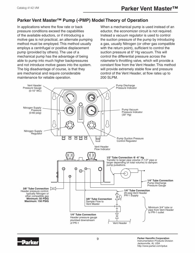
Parker Vent Master™ Pump (-PMP) Model Theory of OperationIn applications where the flow rate or back pressure conditions exceed the capabilities of the available eductors, or if introducing a motive gas is not practical, an alternate pumping method must be employed. This method usually employs a centrifugal or positive displacement pump (provided by others). The use of a mechanical pump has the advantage of being able to pump into much higher backpressures and not introduce motive gases into the system. The big disadvantage of course, is that they are mechanical and require considerable maintenance for reliable operation.
When a mechanical pump is used instead of an eductor, the economizer circuit is not required. Instead a vacuum regulator is used to control the suction pressure of the pump by introducing a gas, usually Nitrogen (or other gas compatible with the return point), sufficient to control the suction pressure at 6" Hg vacuum. This will control the differential pressure across the rotameter’s throttling valve, which will provide a constant flow from the Vent Header. This method will provide extremely stable flow and pressure control of the Vent Header, at flow rates up to 200 SLPM.
10 Parker Hannifin CorporationInstrumentation Products DivisionJacksonville, AL USAhttp://www.parker.com/ipdus
Catalog 4142-VMParker Vent Master™
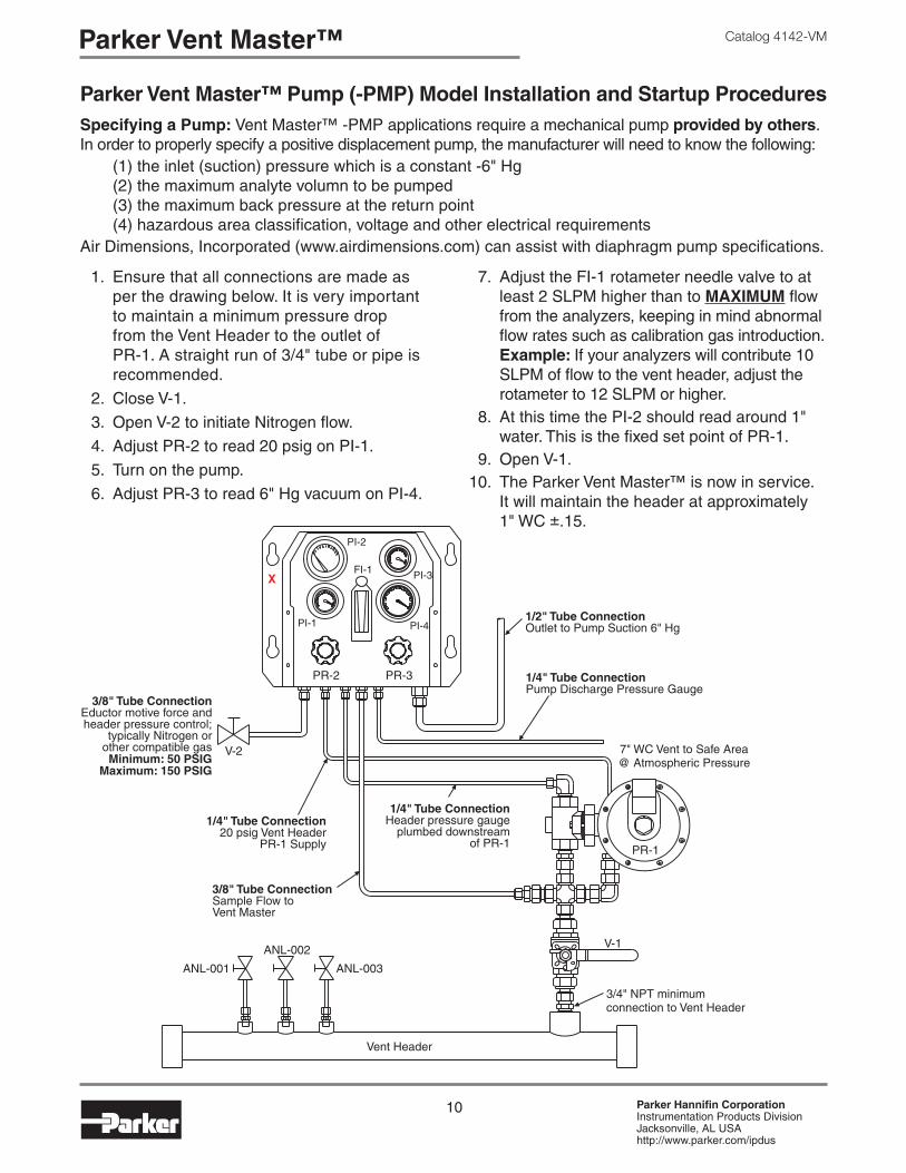
Parker Vent Master™ Pump (-PMP) Model Installation and Startup ProceduresSpecifying a Pump: Vent Master™ -PMP applications require a mechanical pump provided by others. In order to properly specify a positive displacement pump, the manufacturer will need to know the following:
(1) the inlet (suction) pressure which is a constant -6" Hg(2) the maximum analyte volumn to be pumped(3) the maximum back pressure at the return point(4) hazardous area classification, voltage and other electrical requirements
Air Dimensions, Incorporated (www.airdimensions.com) can assist with diaphragm pump specifications.
1. Ensure that all connections are made as per the drawing below. It is very important to maintain a minimum pressure drop from the Vent Header to the outlet of PR-1. A straight run of 3/4" tube or pipe is recommended.
2. Close V-1.
3. Open V-2 to initiate Nitrogen flow.
4. Adjust PR-2 to read 20 psig on PI-1.
5. Turn on the pump.
6. Adjust PR-3 to read 6" Hg vacuum on PI-4.
7. Adjust the FI-1 rotameter needle valve to at least 2 SLPM higher than to MAXIMUM flow from the analyzers, keeping in mind abnormal flow rates such as calibration gas introduction. Example: If your analyzers will contribute 10 SLPM of flow to the vent header, adjust the rotameter to 12 SLPM or higher.
8. At this time the PI-2 should read around 1" water. This is the fixed set point of PR-1.
9. Open V-1. 10. The Parker Vent Master™ is now in service.
It will maintain the header at approximately 1" WC ±.15.
11 Parker Hannifin CorporationInstrumentation Products DivisionJacksonville, AL USAhttp://www.parker.com/ipdus
Catalog 4142-VM Parker Vent Master™
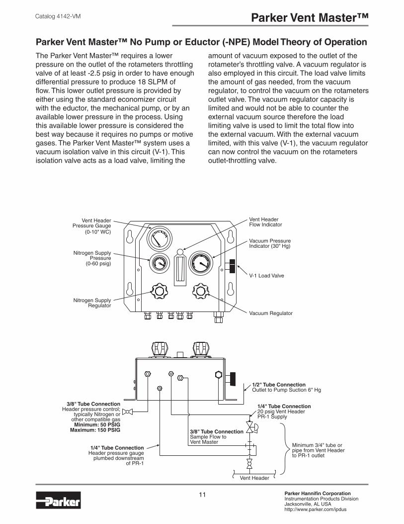
Parker Vent Master™ No Pump or Eductor (-NPE) Model Theory of OperationThe Parker Vent Master™ requires a lower pressure on the outlet of the rotameters throttling valve of at least -2.5 psig in order to have enough differential pressure to produce 18 SLPM of flow. This lower outlet pressure is provided by either using the standard economizer circuit with the eductor, the mechanical pump, or by an available lower pressure in the process. Using this available lower pressure is considered the best way because it requires no pumps or motive gases. The Parker Vent Master™ system uses a vacuum isolation valve in this circuit (V-1). This isolation valve acts as a load valve, limiting the
amount of vacuum exposed to the outlet of the rotameter’s throttling valve. A vacuum regulator is also employed in this circuit. The load valve limits the amount of gas needed, from the vacuum regulator, to control the vacuum on the rotameters outlet valve. The vacuum regulator capacity is limited and would not be able to counter the external vacuum source therefore the load limiting valve is used to limit the total flow into the external vacuum. With the external vacuum limited, with this valve (V-1), the vacuum regulator can now control the vacuum on the rotameters outlet-throttling valve.
12 Parker Hannifin CorporationInstrumentation Products DivisionJacksonville, AL USAhttp://www.parker.com/ipdus
Catalog 4142-VMParker Vent Master™
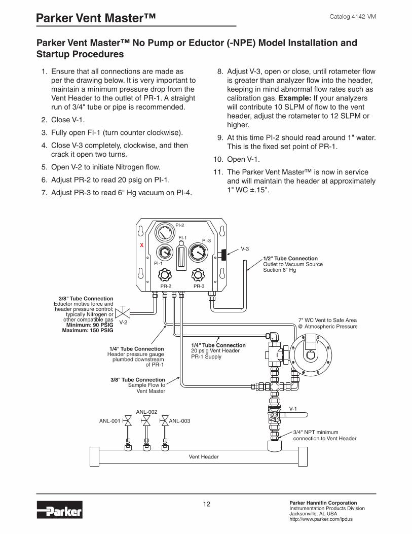
Parker Vent Master™ No Pump or Eductor (-NPE) Model Installation and Startup Procedures
1. Ensure that all connections are made as per the drawing below. It is very important to maintain a minimum pressure drop from the Vent Header to the outlet of PR-1. A straight run of 3/4" tube or pipe is recommended.
2. Close V-1.
3. Fully open FI-1 (turn counter clockwise).
4. Close V-3 completely, clockwise, and then crack it open two turns.
5. Open V-2 to initiate Nitrogen flow.
6. Adjust PR-2 to read 20 psig on PI-1.
7. Adjust PR-3 to read 6" Hg vacuum on PI-4.
8. Adjust V-3, open or close, until rotameter flow is greater than analyzer flow into the header, keeping in mind abnormal flow rates such as calibration gas. Example: If your analyzers will contribute 10 SLPM of flow to the vent header, adjust the rotameter to 12 SLPM or higher.
9. At this time PI-2 should read around 1" water. This is the fixed set point of PR-1.
10. Open V-1.
11. The Parker Vent Master™ is now in service and will maintain the header at approximately 1" WC ±.15".

13 Parker Hannifin CorporationInstrumentation Products DivisionJacksonville, AL USAhttp://www.parker.com/ipdus
Catalog 4142-VM Parker Vent Master™
Dimensions
How to OrderThe correct part number is easily derived from the following example and ordering chart. The seven product characteristics required are coded as shown in the chart. Example 1, below, describes an Eductor A model with a 23 SLPM glass tube rotameter with metric CPI® tube connections on both the Vent Master control box and PR-1 subassembly.Example 2, below, describes a Pump model with a 100 SLPM armored rotameter with imperial tube connections on the Vent Master control box and PR-1 shipped without connections.
Examples: 1: VM - EDR - A - 23 - - TFA - ZM 2: VM - PMP - - 100 - ARM
Rotameter Options
Eductor SelectionModelVent
MasterRotameter
Range
–– ––
PR-1 Options
Tube Connections
– –
Vent Master Model
Eductor Selection*
Rotameter Range (SLPM)**
Rotameter Options
PR-1 Options
Tube Connections
VM
EDREDRNB
ABC
0 to... 3, 8, 15, 23 & 30
Blank Glass Tube with Outlet Needle Valve
ARM� Armored with Outlet Needle Valve
Blank Regulator OnlyTFA PR-1 with Tube
Fitting Assembly (shown above)
Z Imperial CPI™
ZM Metric CPI™
A Imperial A-LOK®
AM Metric A-LOK®
PMP
Blank
0 to... 3, 8, 15, 23, 30, 40, 50, 100, 150, 200 (subject to fluid density)
NPE
* See page 7 for eductor sizing.** The rotameter range is determined by adding 2 SLPM to your MAXIMUM analyzer flow, keeping in mind abnormal flows such as
calibration gas introduction, then rounding up to the next highest range available from the selection chart above.� Armored rotameters are normally used only in applications where QC 3.1B certificates are required. The maximum pressure applied to the
rotameter is -6" Hg.
SpecificationsTemperature Range: -20°F to 140°F (-29°C to 60°C)Wetted Materials of Construction: 316SS and Parker
Parofluor o-rings (Highly Fluorinated Fluorocarbon Rubber) 3.1B Certificate of Conformance available
14 Parker Hannifin CorporationInstrumentation Products DivisionJacksonville, AL USAhttp://www.parker.com/ipdus
Catalog 4142-VMParker Vent Master™
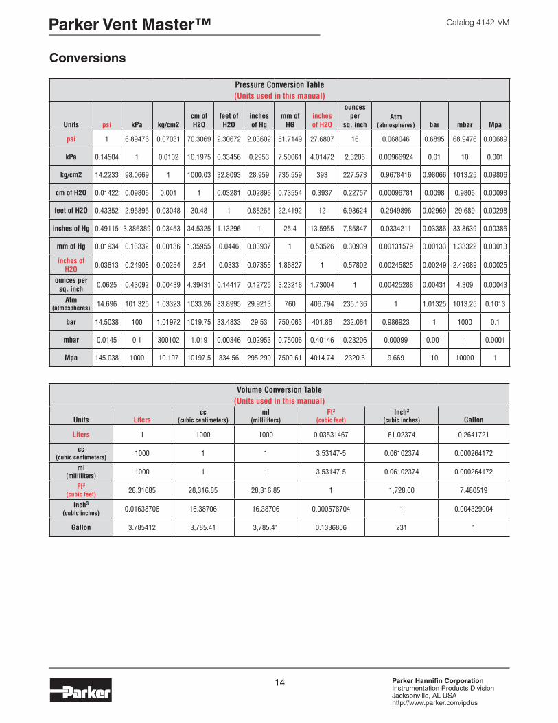
Conversions
Pressure Conversion Table(Units used in this manual)
Units psi kPa kg/cm2cm of H2O
feet of H2O
inches of Hg
mm of HG
inches of H2O
ounces per
sq. inchAtm
(atmospheres) bar mbar Mpa
psi 1 6.89476 0.07031 70.3069 2.30672 2.03602 51.7149 27.6807 16 0.068046 0.6895 68.9476 0.00689
kPa 0.14504 1 0.0102 10.1975 0.33456 0.2953 7.50061 4.01472 2.3206 0.00966924 0.01 10 0.001
kg/cm2 14.2233 98.0669 1 1000.03 32.8093 28.959 735.559 393 227.573 0.9678416 0.98066 1013.25 0.09806
cm of H2O 0.01422 0.09806 0.001 1 0.03281 0.02896 0.73554 0.3937 0.22757 0.00096781 0.0098 0.9806 0.00098
feet of H2O 0.43352 2.96896 0.03048 30.48 1 0.88265 22.4192 12 6.93624 0.2949896 0.02969 29.689 0.00298
inches of Hg 0.49115 3.386389 0.03453 34.5325 1.13296 1 25.4 13.5955 7.85847 0.0334211 0.03386 33.8639 0.00386
mm of Hg 0.01934 0.13332 0.00136 1.35955 0.0446 0.03937 1 0.53526 0.30939 0.00131579 0.00133 1.33322 0.00013
inches of H2O 0.03613 0.24908 0.00254 2.54 0.0333 0.07355 1.86827 1 0.57802 0.00245825 0.00249 2.49089 0.00025
ounces per sq. inch 0.0625 0.43092 0.00439 4.39431 0.14417 0.12725 3.23218 1.73004 1 0.00425288 0.00431 4.309 0.00043
Atm (atmospheres) 14.696 101.325 1.03323 1033.26 33.8995 29.9213 760 406.794 235.136 1 1.01325 1013.25 0.1013
bar 14.5038 100 1.01972 1019.75 33.4833 29.53 750.063 401.86 232.064 0.986923 1 1000 0.1
mbar 0.0145 0.1 300102 1.019 0.00346 0.02953 0.75006 0.40146 0.23206 0.00099 0.001 1 0.0001
Mpa 145.038 1000 10.197 10197.5 334.56 295.299 7500.61 4014.74 2320.6 9.669 10 10000 1
Volume Conversion Table(Units used in this manual)
Units Literscc
(cubic centimeters)ml
(milliliters)Ft3
(cubic feet)Inch3
(cubic inches) Gallon
Liters 1 1000 1000 0.03531467 61.02374 0.2641721
cc (cubic centimeters) 1000 1 1 3.53147-5 0.06102374 0.000264172
ml (milliliters) 1000 1 1 3.53147-5 0.06102374 0.000264172
Ft3 (cubic feet) 28.31685 28,316.85 28,316.85 1 1,728.00 7.480519
Inch3 (cubic inches) 0.01638706 16.38706 16.38706 0.000578704 1 0.004329004
Gallon 3.785412 3,785.41 3,785.41 0.1336806 231 1
15 Parker Hannifin CorporationInstrumentation Products DivisionJacksonville, AL USAhttp://www.parker.com/ipdus
Catalog 4142-VM Parker Vent Master™
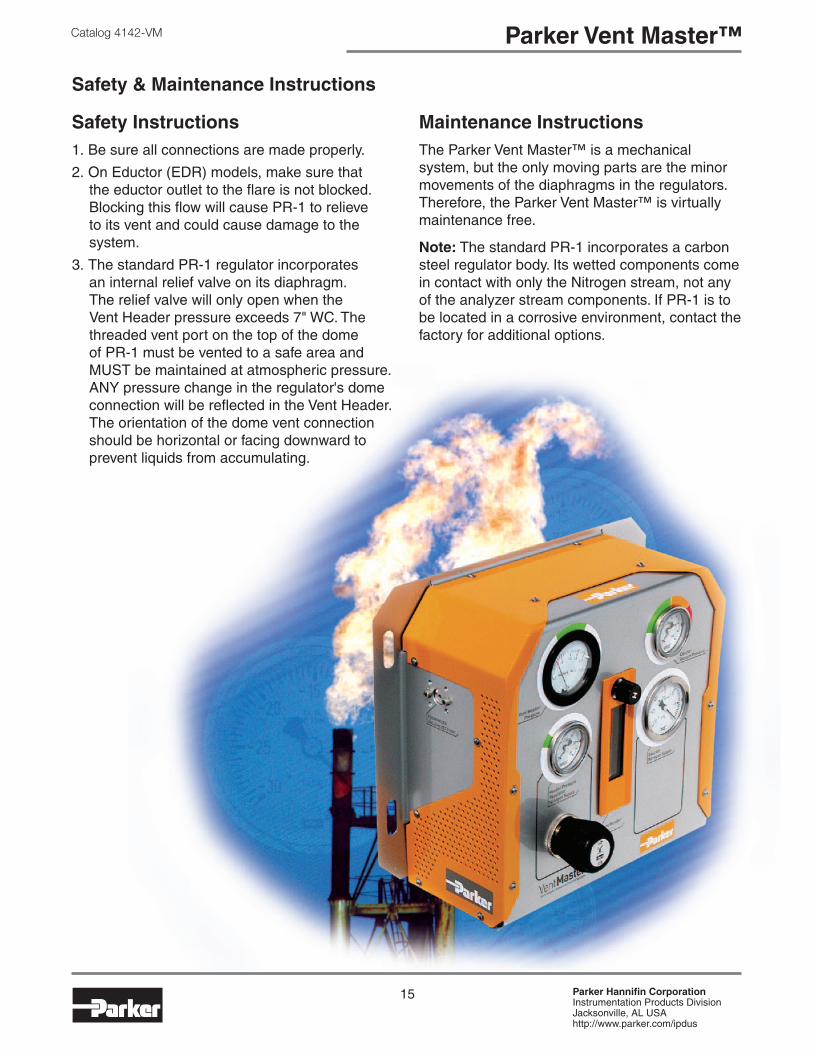
Safety & Maintenance Instructions
Safety Instructions1. Be sure all connections are made properly.
2. On Eductor (EDR) models, make sure that the eductor outlet to the flare is not blocked. Blocking this flow will cause PR-1 to relieve to its vent and could cause damage to the system.
3. The standard PR-1 regulator incorporates an internal relief valve on its diaphragm. The relief valve will only open when the Vent Header pressure exceeds 7" WC. The threaded vent port on the top of the dome of PR-1 must be vented to a safe area and MUST be maintained at atmospheric pressure. ANY pressure change in the regulator's dome connection will be reflected in the Vent Header. The orientation of the dome vent connection should be horizontal or facing downward to prevent liquids from accumulating.
Maintenance Instructions The Parker Vent Master™ is a mechanical system, but the only moving parts are the minor movements of the diaphragms in the regulators. Therefore, the Parker Vent Master™ is virtually maintenance free.
Note: The standard PR-1 incorporates a carbon steel regulator body. Its wetted components come in contact with only the Nitrogen stream, not any of the analyzer stream components. If PR-1 is to be located in a corrosive environment, contact the factory for additional options.

16 Parker Hannifin CorporationInstrumentation Products DivisionJacksonville, AL USAhttp://www.parker.com/ipdus
Catalog 4142-VMOffer of SaleOffer of Sale
The items described in this document and other documents and descriptions provided by Parker Hannifin Corporation, its subsidiaries and its authorized distributors (“Seller”) are hereby offered for sale at prices to be established by Seller. This offer and its acceptance by any customer (“Buyer”) shall be governed by all of the following Terms and Conditions. Buyer’s order for any item described in its document, when communicated to Seller verbally, or in writing, shall constitute acceptance of this offer. All goods or work described will be referred to as “Products”.
1. Terms and Conditions. Seller’s willingness to offer Products, or accept an order for Products, to or from Buyer is expressly conditioned on Buyer’s assent to these Terms and Conditions and to the terms and conditions found on-line at www.parker.com/saleterms/. Seller objects to any contrary or additional term or condition of Buyer’s order or any other document issued by Buyer.
2. Price Adjustments; Payments. Prices stated on the reverse side or preceding pages of this document are valid for 30 days. After 30 days, Seller may change prices to reflect any increase in its costs resulting from state, federal or local legislation, price increases from its suppliers, or any change in the rate, charge, or classification of any carrier. The prices stated on the reverse or preceding pages of this document do not include any sales, use, or other taxes unless so stated specifically. Unless otherwise specified by Seller, all prices are F.O.B. Seller’s facility, and payment is due 30 days from the date of invoice. After 30 days, Buyer shall pay interest on any unpaid invoices at the rate of 1.5% per month or the maximum allowable rate under applicable law.
3. Delivery Dates; Title and Risk; Shipment. All delivery dates are approximate and Seller shall not be responsible for any damages resulting from any delay. Regardless of the manner of shipment, title to any products and risk of loss or damage shall pass to Buyer upon tender to the carrier at Seller’s facility (i.e., when it’s on the truck, it’s yours). Unless otherwise stated, Seller may exercise its judgment in choosing the carrier and means of delivery. No deferment of shipment at Buyers’ request beyond the respective dates indicated will be made except on terms that will indemnify, defend and hold Seller harmless against all loss and additional expense. Buyer shall be responsible for any additional shipping charges incurred by Seller due to Buyer’s changes in shipping, product specifications or in accordance with Section 13, herein.
4. Warranty. Seller warrants that the Products sold here-under shall be free from defects in material or workmanship for a period of twelve months from the date of delivery to Buyer or 2,000 hours of normal use, whichever occurs first. This warranty is made only to Buyer and does not extend to anyone to whom Products are sold after purchased from Seller. The prices charged for Seller’s products are based upon the exclusive limited warranty stated above, and upon the following disclaimer: DISCLAIMER OF WARRANTY: THIS WARRANTY COMPRISES THE SOLE AND ENTIRE WARRANTY PERTAINING TO PRODUCTS PROVIDED HEREUNDER. SELLER DISCLAIMS ALL OTHER WARRANTIES, EXPRESS AND IMPLIED, INCLUDING MERCHANTABILITY AND FITNESS FOR A PARTICULAR PURPOSE.
5. Claims; Commencement of Actions. Buyer shall promptly inspect all Products upon delivery. No claims for shortages will be allowed unless reported to the Seller within 10 days of delivery. No other claims against Seller will be allowed unless asserted in writing within 60 days after delivery or, in the case of an alleged breach of warranty, within 30 days after the date within the warranty period on which the defect is or should have been discovered by Buyer. Any action based upon breach of this agreement or upon any other claim arising out of this sale (other than an action by Seller for any amount due to Seller from Buyer) must be commenced within thirteen months from the date of tender of delivery by Seller or, for a cause of action based upon an alleged breach of warranty, within thirteen months from the date within the warranty period on which the defect is or should have been discovered by Buyer.
6. LIMITATION OF LIABILITY. UPON NOTIFICATION, SELLER WILL, AT ITS OPTION, REPAIR OR REPLACE A DEFECTIVE PRODUCT, OR REFUND THE PURCHASE PRICE. IN NO EVENT SHALL SELLER BE LIABLE TO BUYER FOR ANY SPECIAL, INDIRECT, INCIDENTAL OR CONSEQUENTIAL DAMAGES ARISING OUT OF, OR AS THE RESULT OF, THE SALE, DELIVERY, NON-DELIVERY, SERVICING, USE OR LOSS OF USE OF THE PRODUCTS OR ANY PART THEREOF, OR FOR ANY CHARGES OR EXPENSES OF ANY NATURE INCURRED WITHOUT SELLER’S WRITTEN CONSENT, EVEN IF SELLER HAS BEEN NEGLIGENT, WHETHER IN CONTRACT, TORT OR OTHER LEGAL THEORY. IN NO EVENT SHALL SELLER’S LIABILITY UNDER ANY CLAIM MADE BY BUYER EXCEED THE PURCHASE PRICE OF THE PRODUCTS.
7. Contingencies. Seller shall not be liable for any default or delay in performance if caused by circumstances beyond the reasonable control of Seller.
8. User Responsibility. The user, through its own analysis and testing, is solely responsible for making the final selection of the system and Product and assuring that all performance, endurance, maintenance, safety and warning requirements of the application are met. The user must analyze all aspects of the application and follow applicable industry standards and Product information. If Seller provides Product or system options, the user is responsible for determining that such data and specifications are suitable and sufficient for all applications and reasonably foreseeable uses of the Products or systems.
9. Loss to Buyer’s Property. Any designs, tools, patterns, materials, drawings, confidential information or equipment furnished by Buyer or any other items which become Buyer’s property, may be considered obsolete and may be destroyed by Seller after two consecutive years have elapsed without Buyer placing an order for the items which are manufactured using such property. Seller shall not be responsible for any loss or damage to such property while it is in Seller’s possession or control.
10. Special Tooling. A tooling charge may be imposed for any special tooling, including without limitation, dies, fixtures, molds and patterns, acquired to manufacture Products. Such special tooling shall be and remain Seller’s property notwithstanding payment of any charges by Buyer. In no event will Buyer acquire any interest in apparatus belonging to Seller which is utilized in the manufacture of the Products, even if such apparatus has been specially converted or adapted for such manufacture and notwithstanding any charges paid by Buyer. Unless otherwise agreed, Seller shall have the right to alter, discard or otherwise dispose of any special tooling or other property in its sole discretion at any time.
11. Buyer’s Obligation; Rights of Seller. To secure payment of all sums due or otherwise, Seller shall retain a security interest in the goods delivered and this agreement shall be deemed a Security Agreement under the Uniform Commercial Code. Buyer authorizes Seller as its attorney to execute and file on Buyer’s behalf all documents Seller deems necessary to perfect its security interest. Seller shall have a security interest in, and lien upon, any property of Buyer in Seller’s possession as security for the payment of any amounts owed to Seller by Buyer.
12. Improper use and Indemnity. Buyer shall indemnify, defend, and hold Seller harmless from any claim, liability, damages, lawsuits, and costs (including attorney fees), whether for personal injury, property damage, patent, trademark or copyright infringement or any other claim, brought by or incurred by Buyer, Buyer’s employees, or any other person, arising out of: (a) improper selection, improper application or other misuse of Products purchased by Buyer from Seller; (b) any act or omission, negligent or otherwise, of Buyer; (c) Seller’s use of patterns, plans, drawings, or specifications furnished by Buyer to manufacture Product; or (d) Buyer’s failure to comply with these terms and conditions. Seller shall not indemnify Buyer under any circumstance except as otherwise provided.
13. Cancellations and Changes. Orders shall not be subject to cancellation or change by Buyer for any reason, except with Seller’s written consent and upon terms that will indemnify, defend and hold Seller harmless against all direct, incidental and consequential loss or damage. Seller may change product features, specifications, designs and availability with notice to Buyer.
14. Limitation on Assignment. Buyer may not assign its rights or obligations under this agreement without the prior written consent of Seller.
15. Entire Agreement. This agreement contains the entire agreement between the Buyer and Seller and constitutes the final, complete and exclusive expression of the terms of the agreement. All prior or contemporaneous written or oral agreements or negotiations with respect to the subject matter are herein merged.
16. Waiver and Severability. Failure to enforce any provision of this agreement will not waive that provision nor will any such failure prejudice Seller’s right to enforce that provision in the future. Invalidation of any provision of this agreement by legislation or other rule of law shall not invalidate any other provision herein. The remaining provisions of this agreement will remain in full force and effect.
17. Termination. This agreement may be terminated by Seller for any reason and at any time by giving Buyer thirty (30) days written notice of termination. In addition, Seller may by written notice immediately terminate this agreement for the following: (a) Buyer commits a breach of any provision of this agreement (b) the appointment of a trustee, receiver or custodian for all or any part of Buyer’s property (c) the filing of a petition for relief in bankruptcy of the other Party on its own behalf, or by a third party (d) an assignment for the benefit of creditors, or (e) the dissolution or liquidation of the Buyer.
18. Governing Law. This agreement and the sale and delivery of all Products hereunder shall be deemed to have taken place in and shall be governed and construed in accordance with the laws of the State of Ohio, as applicable to contracts executed and wholly performed therein and without regard to conflicts of laws principles. Buyer irrevocably agrees and consents to the exclusive jurisdiction and venue of the courts of Cuyahoga County, Ohio with respect to any dispute, controversy or claim arising out of or relating to this agreement. Disputes between the parties shall not be settled by arbitration unless, after a dispute has arisen, both parties expressly agree in writing to arbitrate the dispute.
19. Indemnity for Infringement of Intellectual Property Rights. Seller shall have no liability for infringement of any patents, trademarks, copyrights, trade dress, trade secrets or similar rights except as provided in this Section. Seller will defend and indemnify Buyer against allegations of infringement of U.S. patents, U.S. trademarks, copyrights, trade dress and trade secrets (“Intellectual Property Rights”). Seller will defend at its expense and will pay the cost of any settlement or damages awarded in an action brought against Buyer based on an allegation that a Product sold pursuant to this Agreement infringes the Intellectual Property Rights of a third party. Seller’s obligation to defend and indemnify Buyer is contingent on Buyer notifying Seller within ten (10) days after Buyer becomes aware of such allegations of infringement, and Seller having sole control over the defense of any allegations or actions including all negotiations for settlement or compromise. If a Product is subject to a claim that it infringes the Intellectual Property Rights of a third party, Seller may, at its sole expense and option, procure for Buyer the right to continue using the Product, replace or modify the Product so as to make it noninfringing, or offer to accept return of the Product and return the purchase price less a reasonable allowance for depreciation. Notwithstanding the foregoing, Seller shall have no liability for claims of infringement based on information provided by Buyer, or directed to Products delivered hereunder for which the designs are specified in whole or part by Buyer, or infringements resulting from the modification, combination or use in a system of any Product sold hereunder. The foregoing provisions of this Section shall constitute Seller’s sole and exclusive liability and Buyer’s sole and exclusive remedy for infringement of Intellectual Property Rights.
20. Taxes. Unless otherwise indicated, all prices and charges are exclusive of excise, sales, use, property, occupational or like taxes which may be imposed by any taxing authority upon the manufacture, sale or delivery of Products.
21. Equal Opportunity Clause. For the performance of government contracts and where dollar value of the Products exceed $10,000, the equal employment opportunity clauses in Executive Order 11246, VEVRAA, and 41 C.F.R. §§ 60-1.4(a), 60-741.5(a), and 60-250.4, are hereby incorporated.
01/09

AEROSPACEKey Markets• Aircraft engines• Business & general aviation• Commercial transports• Land-based weapons systems• Military aircraft• Missiles & launch vehicles• Regional transports• Unmanned aerial vehicles
Key Products• Flight control systems & components• Fluid conveyance systems• Fluid metering delivery & atomization devices• Fuel systems & components• Hydraulic systems & components• Inert nitrogen generating systems• Pneumatic systems & components• Wheels & brakes
CLIMATE CONTROLKey Markets• Agriculture• Air conditioning• Food, beverage & dairy• Lifesciences&medical• Precision cooling• Processing• Transportation
Key Products• CO2 controls• Electronic controllers• Filter driers• Hand shut-off valves• Hose & fittings• Pressure regulating valves• Refrigerant distributors• Safety relief valves• Solenoid valves• Thermostatic expansion valves
FILTRATIONKey Markets• Food & beverage• Industrial machinery• Life sciences• Marine• Mobile equipment• Oil & gas• Power generation• Process• Transportation
Key Products• Analytical gas generators• Compressed air & gas filters• Condition monitoring• Engine air, fuel & oil filtration & systems• Hydraulic, lubrication & coolant filters• Process, chemical, water & microfiltration filters• Nitrogen, hydrogen & zero air generators
ELECTROMECHANICALKey Markets• Aerospace• Factory automation• Life science & medical• Machine tools• Packaging machinery• Paper machinery• Plastics machinery & converting• Primary metals• Semiconductor & electronics• Textile• Wire & cable
Key Products• AC/DC drives & systems• Electric actuators, gantry robots & slides • Electrohydrostatic actuation systems• Electromechanical actuation systems• Human machine interface• Linear motors• Stepper motors, servo motors, drives & controls• Structural extrusions
PNEUMATICSKey Markets• Aerospace• Conveyor & material handling• Factory automation• Life science & medical• Machine tools• Packaging machinery• Transportation & automotive
Key Products• Air preparation• Brass fittings & valves• Manifolds• Pneumatic accessories• Pneumatic actuators & grippers• Pneumatic valves & controls• Quick disconnects• Rotary actuators• Rubber & thermoplastic hose & couplings• Structural extrusions• Thermoplastic tubing & fittings• Vacuum generators, cups & sensors
FLUID & GAS HANDLINGKey Markets• Aerospace• Agriculture• Bulk chemical handling• Construction machinery• Food & beverage• Fuel & gas delivery• Industrial machinery• Mobile• Oil & gas• Transportation• Welding
Key Products• Brass fittings & valves• Diagnostic equipment • Fluid conveyance systems• Industrial hose• PTFE & PFA hose, tubing & plastic fittings• Rubber & thermoplastic hose & couplings• Tube fittings & adapters• Quick disconnects
HYDRAULICSKey Markets• Aerospace• Aerial lift• Agriculture• Construction machinery• Forestry• Industrial machinery• Mining• Oil & gas• Power generation & energy• Truck hydraulics
Key Products• Diagnostic equipment• Hydraulic cylinders & accumulators• Hydraulic motors & pumps• Hydraulic systems• Hydraulic valves & controls• Power take-offs • Rubber & thermoplastic hose & couplings• Tube fittings & adapters• Quick disconnects
PROCESS CONTROLKey Markets• Chemical & refining• Food, beverage & dairy• Medical & dental• Microelectronics• Oil & gas• Power generation
Key Products• Analytical sample
conditioning products & systems
• Fluoropolymer chemical delivery fittings, valves & pumps
• High purity gas delivery fittings, valves & regulators
• Instrumentation fittings, valves & regulators
• Medium pressure fittings & valves
• Process control manifolds
SEALING & SHIELDINGKey Markets• Aerospace• Chemical processing• Consumer• Energy, oil & gas• Fluid power• General industrial• Information technology• Life sciences• Military• Semiconductor• Telecommunications• Transportation
Key Products• Dynamic seals• Elastomeric o-rings • EMI shielding• Extruded & precision-cut, fabricated elastomeric seals• Homogeneous & inserted elastomeric shapes • High temperature metal seals• Metal & plastic retained composite seals• Thermal management
Parker’s Motion & Control TechnologiesAt Parker, we’re guided by
a relentless drive to help
our customers become more
productive and achieve
higher levels of profitabil-
ity by engineering the best
systems for their require-
ments. It means looking at
customer applications from
many angles to find new
ways to create value. What-
ever the motion and control
technology need, Parker has
the experience, breadth of
product and global reach
to consistently deliver. No
company knows more about
motion and control technol-
ogy than Parker. For further
info call 1-800-C-Parker.

Parker Hannifin CorporationInstrumentation Products Division2651 Alabama Highway 21 NorthJacksonville, AL 36265-681phone 256 435 2130fax 256 435 7718www.parker.com/ipdus
Europe, Middle East, AfricaAE – United Arab Emirates, Dubai Tel: +971 4 8127100 [email protected]
AT – Austria, Wiener Neustadt Tel: +43 (0)2622 23501-0 [email protected]
AT – Eastern Europe, Wiener Neustadt Tel: +43 (0)2622 23501 900 [email protected]
AZ – Azerbaijan, Baku Tel: +994 50 2233 458 [email protected]
BE/LU – Belgium, Nivelles Tel: +32 (0)67 280 900 [email protected]
BG – Bulgaria, Sofia Tel: +359 2 980 1344 [email protected]
BY – Belarus, Minsk Tel: +375 17 209 9399 [email protected]
CH – Switzerland, Etoy Tel: +41 (0)21 821 87 00 [email protected]
CZ – Czech Republic, Klecany Tel: +420 284 083 111 [email protected]
DE – Germany, Kaarst Tel: +49 (0)2131 4016 0 [email protected]
DK – Denmark, Ballerup Tel: +45 43 56 04 00 [email protected]
ES – Spain, Madrid Tel: +34 902 330 001 [email protected]
FI – Finland, Vantaa Tel: +358 (0)20 753 2500 [email protected]
FR – France, Contamine s/Arve Tel: +33 (0)4 50 25 80 25 [email protected]
GR – Greece, Athens Tel: +30 210 933 6450 [email protected]
HU – Hungary, Budaörs Tel: +36 23 885 470 [email protected]
IE – Ireland, Dublin Tel: +353 (0)1 466 6370 [email protected]
IT – Italy, Corsico (MI) Tel: +39 02 45 19 21 [email protected]
KZ – Kazakhstan, Almaty Tel: +7 7273 561 000 [email protected]
NL – The Netherlands, Oldenzaal Tel: +31 (0)541 585 000 [email protected]
NO – Norway, Asker Tel: +47 66 75 34 00 [email protected]
PL – Poland, Warsaw Tel: +48 (0)22 573 24 00 [email protected]
PT – Portugal, Leca da Palmeira Tel: +351 22 999 7360 [email protected]
RO – Romania, Bucharest Tel: +40 21 252 1382 [email protected]
RU – Russia, Moscow Tel: +7 495 645-2156 [email protected]
SE – Sweden, Spånga Tel: +46 (0)8 59 79 50 00 [email protected]
SK – Slovakia, Banská Bystrica Tel: +421 484 162 252 [email protected]
SL – Slovenia, Novo Mesto Tel: +386 7 337 6650 [email protected]
TR – Turkey, Istanbul Tel: +90 216 4997081 [email protected]
UA – Ukraine, Kiev Tel +380 44 494 2731 [email protected]
UK – United Kingdom, Warwick Tel: +44 (0)1926 317 878 [email protected]
ZA – South Africa, Kempton Park Tel: +27 (0)11 961 0700 [email protected]
North AmericaCA – Canada, Milton, Ontario Tel: +1 905 693 3000
US – USA, Cleveland Tel: +1 216 896 3000
Asia PacificAU – Australia, Castle Hill Tel: +61 (0)2-9634 7777
CN – China, Shanghai Tel: +86 21 2899 5000
HK – Hong Kong Tel: +852 2428 8008
IN – India, Mumbai Tel: +91 22 6513 7081-85
JP – Japan, Tokyo Tel: +81 (0)3 6408 3901
KR – South Korea, Seoul Tel: +82 2 559 0400
MY – Malaysia, Shah Alam Tel: +60 3 7849 0800
NZ – New Zealand, Mt Wellington Tel: +64 9 574 1744
SG – Singapore Tel: +65 6887 6300
TH – Thailand, Bangkok Tel: +662 186 7000-99
TW – Taiwan, Taipei Tel: +886 2 2298 8987
South AmericaAR – Argentina, Buenos Aires Tel: +54 3327 44 4129
BR – Brazil, Sao Jose dos Campos Tel: +55 800 727 5374
CL – Chile, Santiago Tel: +56 2 623 1216
MX – Mexico, Toluca Tel: +52 72 2275 4200
Catalog 4142-VM 02/2014-DDP
Your local authorized Parker distributor
© 2014 Parker Hannifin Corporation. All rights reserved.
Parker Worldwide