Parker pneumatic catalogue deel 2
282
499 Parker Hannifin Corporation Pneumatic Division - Europe PDE2600PNUK Parker Pneumatic Industrial Communication Industrial Communication System Isysnet system for centralised and decentralised applications Isysnet System for Centralised applications Isysnet System has 4 major components : • Communication interface modules provide the network- interface circuitry • I/O modules provide the field interface, system-interface circuitry, and bases for mounting • Power distribution module provide the solution to expandability of the Isysnet system or multiple power supply Moduflex Bus System for Decentralised applications The Moduflex communication module is directly attach the either, a Moduflex, Isys Micro or Isys ISO manifold in a compact valve island directly connectable to the industrial network. Isysnet / Moduflex
description
Â
Transcript of Parker pneumatic catalogue deel 2

499
Parker Hannifin CorporationPneumatic Division - Europe
PDE2600PNUK
Parker Pneumatic Industrial Communication
IndustrialCommunication System
Isysnet system for centralised anddecentralised applications
Isysnet System for Centralised applications
Isysnet System has 4 major components :•Communication interface modules provide the network- interface circuitry•I/O modules provide the field interface, system-interface circuitry, and bases for mounting•Power distribution module provide the solution to expandability of the Isysnet system or multiple power supply
Moduflex Bus System for Decentralisedapplications
The Moduflex communication module is directly attach the either, a Moduflex, Isys Micro or Isys ISO manifold in a compact valve island directly connectable to theindustrial network.
Isysnet / Moduflex

500
Parker Hannifin CorporationPneumatic Division - Europe
PDE2600PNUK
Parker Pneumatic
Pneumatic variants using Isysnet Industrial communication system for Centralised applications
Isysnet device with electric modules only Isysnet with Isys Micro extended device
Isysnet with Isys Micro Valves island Isysnet with Isys ISO valves island
Pneumatic variants using Moduflex Fieldbus modules for Decentralised applications
Moduflex Bus with Moduflex Valve System Moduflex Bus with Isys Micro Valves island
Moduflex Bus With Isys ISO 15407-2 or 5599-2 valves island
Isys ISO 15407-2 – HA & HBIsys ISO 5599-2 – H1
Isys ISO 15407-2 – HA & HBIsys ISO 5599-2 – H1
Industrial Communication

501
Parker Hannifin CorporationPneumatic Division - Europe
PDE2600PNUK
Parker Pneumatic
Isysnet Device constitution overview for a Centralised application
For main device For both main and extended devices
For extended device
Communication modules :•FieldbusorIndustrial Ethernet protocol•Networkconnection•Separated24VDCforlogic and user power supply•Configurationwithcodding wells and bus status display by LED
Bus extender cable :•Cablelinkingextended device through the Sub-net- work•Sub-networkconnection from Isysnet module or Isys Micro Valve driver•Transferingbothsub-net- work communication and 5VDC for bus power supply
I/O modules :•ChoiceofDigitalorAnalogic I/O modules offering multiple industrial connection types•Connectiontothe Sub-network and the separated 24VDC for both logic and user through the socket• I/Oandsub-networkstatus display by LEDs
Power extender module :•Additionalseparated 24VDC power supply for logic and user allowing multiple permanant or safety power supply recommandations•BothLogicandUser electrical power supply display by separated LEDs
Isysnet end section :•Specificsocketorvalve driver without extender bus connector for Isysnet end section
Isysnet prologation section :•Specificsocketwithsub- network extender cable and extended device head plate•Valvedriverincluding extender bus connector for sub-network continuity
Moduflex constitution overview for a Decentralised application
Communication module :•Fieldbusprotocols•Networkconnection•Separatedpowersupplyforcommmunicationandsolenoid valves•Addressingandspeedcommunicationconfigurationby codding wells•BusstatusdisplaybyLED
Bus module adaptor :Using the appropriate adaptor, the Moduflex Bus module canbe assembled to :•ModuflexValveSystem• IsysMicro• IsysISO15407-2–HA&HB• IsysISO5599-2–H1
Industrial Communication

502
Parker Hannifin CorporationPneumatic Division - Europe
PDE2600PNUK
Parker Pneumatic
Isysnet Industrial Communication modules
A choice of different protocols to connect the Isysnet device to the requested industrial network :
• DeviceNet
•ProfibusDP
•ControlNet
•EthernetI/P
Isysnet extension power supply module :
The auxiliary power from the communication module supports up to 10 I/O modules. Also, for application needing a huge I/O modules quantity, this 24VDC extension power moduleextends the backplane bus power to support up to 10 more I/O modules.
Also, when safety recommandations require multiple permanant and safety power supplies, this 24VDC extension power module avoide to get a separated power supply section in the Isysnet device.
Isysnet and Isys Micro bus extender cable
An Isysnet device can be splited into the Isysnet section or, from an Isys Micro valve manifold to an extended Isysnet section.Both cables avoide the backplane Bus power andcommunication.
The Isysnet device has to be closed with a 32 output driver(internally ending the backplane bus) or using the Isysnetterminating base module
Digital and Analogue Isysnet I/O modules :
Application always needs a wide sensor quantity, diversity and additional electric actuators as well, with an appropirate electrical connection.With a modularity from 2 to 16 chanels, the wide Isysnet range of digital or analogue inputs and outputs modules offers a choice of industrial connection :
• M8 -3 PINs
•M12-5PINs
•M23-12PINs
Industrial Communication

503
Parker Hannifin CorporationPneumatic Division - Europe
PDE2600PNUK
Parker Pneumatic
Isysnet 32 Outputs driver for valve islands in centralised applications
• Isys Micro valve nominal flow up to 280 NI/mn
•32outputspermoduletohandleupto32solenoidsper
valve island
•Upto4valveislandslinkedthroughtheinternalsub-network
for a total of 128 solenoids per device
•Withorwithoutadditionaluserpowersupply
•Withorwithoutbusextender
Isysnet 32 Outputs driver for Isys Micro Valve Islands
• ISO 15407-2 Size 02 (HB) 18 mm 380 NI/mn
• ISO 15407-2 Size 01 (HA) 26 mm 590 NI/mn
• ISO 5599-2 Size 1 (H1) 42 mm 1030 NI/mn
• 32 outputs per module to handle up to 32 solenoids per
valve island.
Isysnet 32 Outputs driver for Isys ISO Valve Islands
ISO 15407-2 ISO 5599-2
Moduflex fieldbus modules for valve islands in decentralised applications
• Compatible with all Moduflex fieldbus protocol modules
handling up to 16 solenoids:
- DeviceNet
- CANopen
- Profibus DP
- InterBus-S
- AS-i standard and extended a-b coding versions.
Moduflex fieldbus adaptor for Isys Micro and Isys ISO valve islands
Moduflex valve system Isys Micro
ISO 15407-2
HA - HB
ISO 5599-2
H1
Industrial Communication
504
Parker Hannifin CorporationPneumatic Division - Europe
PDE2600PNUK
Parker Pneumatic
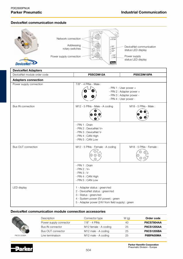
DeviceNet communication module
Network connection
Addressingrotary switches
Power supply connection
DeviceNet communicationstatus LED display
Power supplystatus LED display
DeviceNet Adapters DeviceNet module order code PSSCDM12A PSSCDM18PA
Adapters connection Power supply connection 7/8" - 4 PINs - Male : - PIN 1 : User power + - PIN 2 : Adapter power + - PIN 3 : Adapter power - - PIN 4 : User power -
Bus IN connection M12 - 5 PINs - Male - A coding M18 - 5 PINs - Male :
- PIN 1 : Drain - PIN 2 : DeviceNet V+ - PIN 3 : DeviceNet V- - PIN 4 : CAN High - PIN 5 : CAN Low
Bus OUT connection M12 - 5 PINs - Female - A coding M18 - 5 PINs - Female :
- PIN 1 : Drain - PIN 2 : V+ - PIN 3 : V- - PIN 4 : CAN High - PIN 5 : CAN Low
LED display 1 - Adapter status : green/red 2 - DeviceNet status : green/red 3 - Status : green/red 4 - System power (5V power) : green 5 - Adapter power (24V from field supply) : green
DeviceNet communication module connection accessories
Description Connector type W (g) Order code
Power supply connector 7/8" - 4 PINs 40 P8CS7804AA
Bus IN connector M12 female - A coding 25 P8CS1205AA
Bus OUT connector M12 male - A coding 25 P8CS1205BA
Line terminaison M12 male - A coding 25 P8BPA00MAP8CS1205BA
Industrial Communication

505
Parker Hannifin CorporationPneumatic Division - Europe
PDE2600PNUK
Parker Pneumatic
Profibus DP communication module
Network connection
Addressingrotary switches
Power supply connection
Profibus DP communicationstatus LED display
Power supplystatus LED display
Profibus DP communication module connection accessories
Description Connector type W (g) Order code
Power supply connector 7/8" - 5 PINs 40 P8CS7805AA
Bus IN connector M12 female - B coding 25 P8CS1205AB
Bus OUT connector M12 male - B coding 25 P8CS1205BB
Line terminaison M12 male - B coding 25 P8BPA00MBP8CS1205BB
Profibus DP Adapters Profibus DP module order code PSSCPBA
Profibus DP adapters connection Power supply connection 7/8" - 5 PINs - Male : - PIN 1 : User power - - PIN 2 : Adapter power - - PIN 3 : Protective GND - PIN 4 : Adapter power + - PIN 5 : User power +
BUS IN connection M12 - 5 PINs - Male - B coding - PIN 1 : + 5 VDC Bus - PIN 2 : A - Line - PIN 3 : GND Bus - PIN 4 : B - Line - PIN 5 : Shield
BUS OUT connection M12 - 5 PINs - Female - B coding - PIN 1 : + 5 VDC Bus - PIN 2 : A - Line - PIN 3 : GND Bus - PIN 4 : B - Line - PIN 5 : Shield
LED display 1 - Adapter status : green/red 2 - Profibus DP status : green/red 3 - Bus status : green/red 4 - System power (5V power) : green 5 - Adapter power (24V from field supply) : green
Industrial Communication

506
Parker Hannifin CorporationPneumatic Division - Europe
PDE2600PNUK
Parker Pneumatic
ControlNet communication module
Network connection
Addressingrotary switches
Power supply connectionControlNet communicationstatus LED display
Power supplystatus LED display
ControlNet communication module connection accessories
Description Connector type W (g) Order code
Power supply connector 7/8" - 4 PINs 40 P8CS7804AA
P8CS7804AA
ControlNet Adapters ControlNet module order code PSSCCNA
ControlNet adapters connection Power supply connection 7/8" - 4 PINs - Male : - PIN 1 : User power + - PIN 2 : Adapter power + - PIN 3 : Adapter power - - PIN 4 : User power - ControlNet IN connection TNC style connector
ControlNet OUT connection TNC style connector
LED display 1 - Adapter status : green/red 2 - Bus status : green/red 3 - ControNet A status : green/red 4 - ControNet B status : green/red 5 - System power (Bus 5V power) : green 6 - Adapter power (24V from field supply) : green
tm
Industrial Communication

507
Parker Hannifin CorporationPneumatic Division - Europe
PDE2600PNUK
Parker Pneumatic
Ethernet I/P communication module
Network connection
Addressingrotary switches
Power supply connection
Ethernet I/P communicationstatus LED display
Power supplystatus LED display
Ethernet I/P communication module connection accessories
Description Connector type W (g) Order code
Power supply connector 7/8" - 4 PINs 40 P8CS7804AA
P8CS7804AA
Ethernet I/P Adapters Ethernet I/P module order code PSSCENA
Ethernet I/P adapters connection Power supply connection 7/8" - 4 PINs - Male : - PIN 1 : User power + - PIN 2 : Adapter power + - PIN 3 : Adapter power - - PIN 4 : User power -
Ethernet I/P connection M12 - 4 PINs - Female - D coding : - PIN 1 : Tx + - PIN 2 : Rx + - PIN 3 : Tx - - PIN 4 : Rx - LED display 1 - Adapter status : green/red 2 - Network activity : green 3 - Network status : green/red 4 - Bus status : green/red 5 - System power (Bus 5V power) : green 6 - Adapter power (24V from field supply) : green
Industrial Communication
508
Parker Hannifin CorporationPneumatic Division - Europe
PDE2600PNUK
Parker Pneumatic
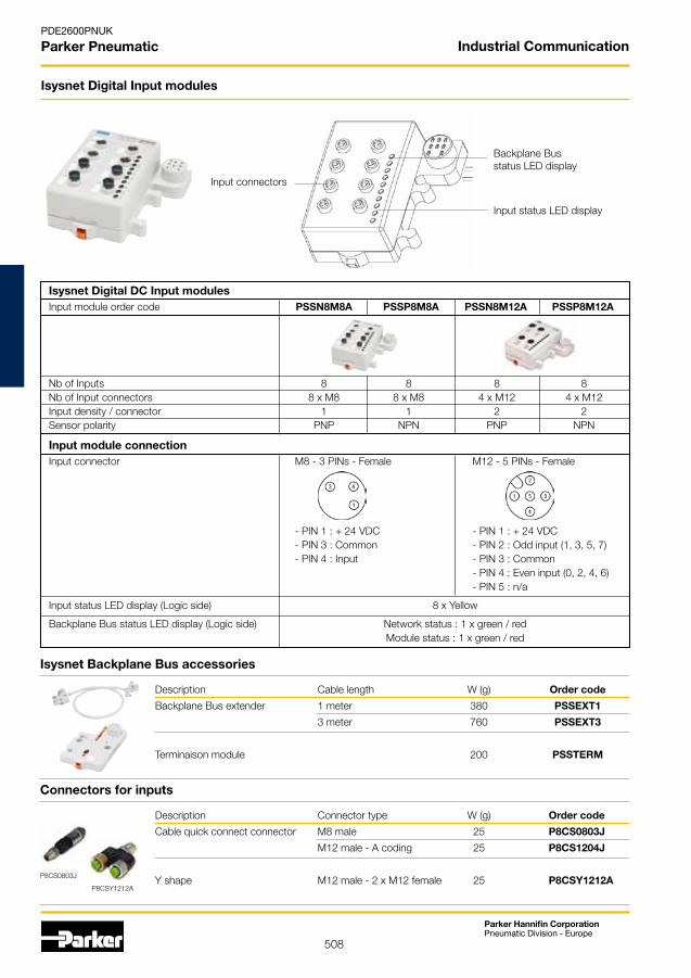
Isysnet Digital Input modules
Input connectors
Backplane Busstatus LED display
Input status LED display
Isysnet Backplane Bus accessories
Description Cable length W (g) Order code
Backplane Bus extender 1 meter 380 PSSEXT1
3 meter 760 PSSEXT3
Terminaison module 200 PSSTERM
Isysnet Digital DC Input modules Input module order code PSSN8M8A PSSP8M8A PSSN8M12A PSSP8M12A
Nb of Inputs 8 8 8 8 Nb of Input connectors 8 x M8 8 x M8 4 x M12 4 x M12 Input density / connector 1 1 2 2 Sensor polarity PNP NPN PNP NPN
Input module connection Input connector M8 - 3 PINs - Female M12 - 5 PINs - Female
- PIN 1 : + 24 VDC - PIN 1 : + 24 VDC - PIN 3 : Common - PIN 2 : Odd input (1, 3, 5, 7) - PIN 4 : Input - PIN 3 : Common - PIN 4 : Even input (0, 2, 4, 6) - PIN 5 : n/a
Input status LED display (Logic side) 8 x Yellow
Backplane Bus status LED display (Logic side) Network status : 1 x green / red Module status : 1 x green / red
Connectors for inputs
Description Connector type W (g) Order code
Cable quick connect connector M8 male 25 P8CS0803J
M12 male - A coding 25 P8CS1204J
Y shape M12 male - 2 x M12 female 25 P8CSY1212AP8CS0803J
P8CSY1212A
Industrial Communication
509
Parker Hannifin CorporationPneumatic Division - Europe
PDE2600PNUK
Parker Pneumatic
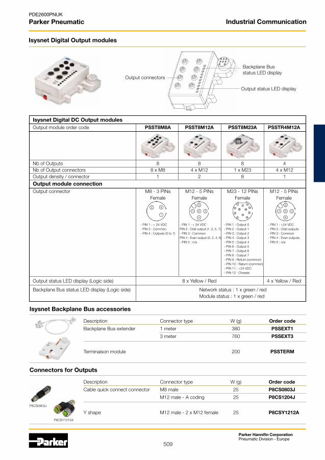
Isysnet Digital DC Output modules Output module order code PSST8M8A PSST8M12A PSST8M23A PSSTR4M12A
Nb of Outputs 8 8 8 4 Nb of Output connectors 8 x M8 4 x M12 1 x M23 4 x M12 Output density / connector 1 2 8 1
Output module connection Output connector M8 - 3 PINs M12 - 5 PINs M23 - 12 PINs M12 - 5 PINs Female Female Female Female
- PIN 1 : + 24 VDC - PIN 1 : + 24 VDC - PIN 1 : Output 0 - PIN 1 : +24 VDC - PIN 3 : Common PIN 2 : Odd output (1, 3, 5, 7) - PIN 2 : Output 1 - PIN 2 : Odd outputs - PIN 4 : Outputs (0 to 7) - PIN 3 : Common - PIN 3 : Output 2 - PIN 3 : Common PIN 4 : Even output (0, 2, 4, 6) - PIN 4 : Output 3 - PIN 4 : Even outputs - PIN 5 : n/a - PIN 5 : Output 4 - PIN 5 : n/a - PIN 6 : Output 5 - PIN 7 : Output 6 - PIN 8 : Output 7 - PIN 9 : Return (common) - PIN 10 : Return (common) - PIN 11 : +24 VDC - PIN 12 : Chassis
Output status LED display (Logic side) 8 x Yellow / Red 4 x Yellow / Red
Backplane Bus status LED display (Logic side) Network status : 1 x green / red Module status : 1 x green / red
Isysnet Digital Output modules
Output connectors
Backplane Busstatus LED display
Output status LED display
Isysnet Backplane Bus accessories
Description Connector type W (g) Order code
Backplane Bus extender 1 meter 380 PSSEXT1
3 meter 760 PSSEXT3
Terminaison module 200 PSSTERM
Connectors for Outputs
Description Connector type W (g) Order code
Cable quick connect connector M8 male 25 P8CS0803J
M12 male - A coding 25 P8CS1204J
Y shape M12 male - 2 x M12 female 25 P8CSY1212AP8CS0803J
P8CSY1212A
Industrial Communication
510
Parker Hannifin CorporationPneumatic Division - Europe
PDE2600PNUK
Parker Pneumatic
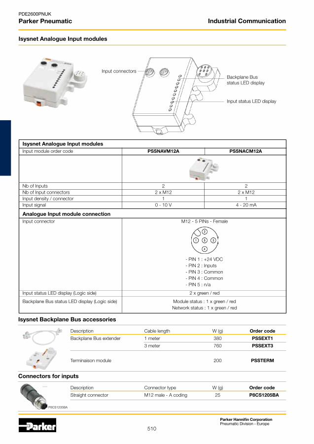
Isysnet Analogue Input modules Input module order code PSSNAVM12A PSSNACM12A
Nb of Inputs 2 2 Nb of Input connectors 2 x M12 2 x M12 Input density / connector 1 1 Input signal 0 - 10 V 4 - 20 mA
Analogue Input module connection Input connector M12 - 5 PINs - Female
- PIN 1 : +24 VDC - PIN 2 : Inputs - PIN 3 : Common - PIN 4 : Common - PIN 5 : n/a
Input status LED display (Logic side) 2 x green / red
Backplane Bus status LED display (Logic side) Module status : 1 x green / red Network status : 1 x green / red
Isysnet Analogue Input modules
Input connectorsBackplane Busstatus LED display
Input status LED display
Isysnet Backplane Bus accessories
Description Cable length W (g) Order code
Backplane Bus extender 1 meter 380 PSSEXT1
3 meter 760 PSSEXT3
Terminaison module 200 PSSTERM
Connectors for inputs
Description Connector type W (g) Order code
Straight connector M12 male - A coding 25 P8CS1205BA
P8CS1205BA
Industrial Communication

511
Parker Hannifin CorporationPneumatic Division - Europe
PDE2600PNUK
Parker Pneumatic
Isysnet Analogue Output modules
Input connectorsBackplane Busstatus LED display
Input status LED display
Isysnet Backplane Bus accessories
Description Cable length W (g) Order code
Backplane Bus extender 1 meter 380 PSSEXT1
3 meter 760 PSSEXT3
Terminaison module 200 PSSTERM
Connectors for Outputs
Description Connector type W (g) Order code
Straight connector M12 male - A coding 25 P8CS1205BA
Isysnet Analogue Output modules Output module order code PSSTAVM12A PSSTACM12A
Nb of Outputs 2 2 Nb of Output connectors 2 x M12 2 x M12 Output density / connector 1 1 Output signal 0 - 10 V 4 - 20 mA
Analogue Output module connection Output connector M12 - 5 PINs - Female
- PIN 1 : Outputs - PIN 2 : +24 VDC - PIN 3 : Common - PIN 4 : Common - PIN 5 : n/a
Output status LED display (Logic side) 2 x green / red
Backplane Bus status LED display (Logic side) Module status : 1 x green / red Network status : 1 x green / red
P8CS1205BA
Industrial Communication

512
Parker Hannifin CorporationPneumatic Division - Europe
PDE2600PNUK
Parker Pneumatic
Isysnet 32 Output driver modules Dedicated valve range Isys Micro Isys ISO 15407-2 Isys ISO 5599-2
32 Output driver modules Side ported PSML61AP PSMM61AP PSMM71AP PSMM51AP PS5620L61P PS4020L61CP
order code Bottom ported PSML62AP PSMM62AP PSMM72AP PSMM52AP - -
Pneumatic port sizes Power supply G3/8" Exhaust G3/8" Pneumatic pilot port sizes Power supply Internal or M7 Internal Exhaust G1/8" Internal
32 Output driver module connection
24 VDC power supply connector NO YES YES NO NO NO M12 - 5 PINs - Male
- PIN 1 : +24 VDC - PIN 2 : n/a - PIN 3 : Common - PIN 4 : n/a - PIN 5 : Protective Earth
Backplane Bus Extender connector NO NO YES YES NO NO
M12 - 5 PINs - Female To use with PSSVEXT1 - PIN 1 : CAN SHLD - PIN 2 : CAN V+ - PIN 3 : CAN GND - PIN 4 : CAN High - PIN 5 : CAN Low
Backplane Bus status LED display (Logic side) Backplane Bus power supply : 1 x green / red Module status : 1 x green / red Backplane Bus status : 1 x green / red Backplane Bus status : 1 x green/red Output fault : 1 x red Output fault : 1 x yellow / red Valve power supply : 1 x green
Isysnet 32 Output drivers
Additional24 VDC power supply connector
(optional)
Backplane Bus status LED display
User power LED display
Accessories
Description Connector type W (g) Order code
Backplane Bus extension cable M12 male - A coding 380 PSSVEXT1 with 1 meter cable Head plate
Connector for M12 Female - A coding 25 P8CS1205AA 24 VDC power supply connector
Line terminaison M12 Male - A coding 25 P8BPA00MA
Backplane Bus extender connector(optional)
Backplane Bus and Solenoid Valves Power Supply Sourcing :
Isys Micro 32 output driver modules Isys ISO 32 output driver modules
Backplane Bus power supplySolenoid Valves power supply
For further details on Multiple Power supply,see at end of this section.
PSML6xAPPSMM5xAP
PS5620L61P PS4020L61CP
PSMM6xAPPSMM7xAP
PSSVEXT1
PSSVEXT1
P8CS1205AA
Industrial Communication

513
Parker Hannifin CorporationPneumatic Division - Europe
PDE2600PNUK
Parker Pneumatic
Backplane Bus Extension Power Supply module Power Supply Extender module Order Code PSSE24A
Extender module connection Power supply connection 7/8" - 4 PINs - Male - PIN 1 : User power + - PIN 2 : Backplane bus power + - PIN 3 : Backplane bus power + - PIN 4 : User power -
Status LED display (Logic side) Field power status : 1 x green 5 VDC system power status : 1 x green
Isysnet Power Extender module
Additional power supply connector
Backplane Busstatus LED display
User power LED display
Isysnet Backplane Bus connector
Description Connector type W (g) Order code
power supply connector 7/8" - 4 PINs 40 P8CS7804AA
Isysnet Backplane Bus accessories
P8CS7804AA
Description Cable length W (g) Order code
Backplane Bus extender 1 meter 380 PSSEXT1 from Isysnet module 3 meter 760 PSSEXT3
Backplane Bus extension cable 1 meter 380 PSSVEXT1 from 32 outputs driver
Industrial Communication

514
Parker Hannifin CorporationPneumatic Division - Europe
PDE2600PNUK
Parker Pneumatic
DeviceNet 16 outputs communication module
Bus OUT connection
Module display & setting
Valve range adapters
Description Valve range W (g) Order code
Moduflex Bus adapter Moduflex Valve 30 P2M2HEV0B without communication module Isys Micro Side ported 200 PSMM41AP Bottom ported 200 PSMM42AP Isys ISO 15407-2 - HA - HB 200 PS5620M41P Isys ISO 5599-2 - H1 300 PS4020M41CP
DeviceNet Adapters Dedicated valve range Moduflex Valve System Isys Micro
DeviceNet module Order Code P2M2HBVD11600 P2M2HBVD21600 Side ported : PSMMD1AP
Bottom ported : PSMMD2AP
Adapter connection Power supply connection M12 - 5 PINs - Male - B coding M12 - 5 PINs - Male - A coding - PIN 1 : n/a - PIN 1 : n/a - PIN 2 : n/a - PIN 2 : n/a - PIN 3 : 0 VDC Solenoids - PIN 3 : 0 VDC Solenoids - PIN 4 : 24 VDC Solenoids - PIN 4 : 24 VDC Solenoids - PIN 5 : Protected earth (PE) - PIN 5 : Protected earth (PE)
Bus IN connection M12 - 5 PINs - Male - A coding - PIN 1 : Drain - PIN 2 : CAN V+ - PIN 3 : CAN V- - PIN 4 : CAN High - PIN 5 : CAN Low
Bus OUT connection M12 - 5 PINs - Female - A coding - PIN 1 : Drain - PIN 2 : CAN V+ - PIN 3 : CAN V- - PIN 4 : CAN High - PIN 5 : CAN Low
LED Display Adapter power : 1 x green DeviceNet status : 2 x green/red Solenoid pilots power : 1 x green/red Solenoid pilots diagnostic : 4 x red
Bus IN connection
Solenoid power supply
P8MM41AP
DeviceNet communication module connection accessories Description Connection type W (g) Order code
Power supply connector M12 Female - A coding 40 P8CS1205AA M12 Female - B coding 40 P8CS1205AB Bus IN connector M12 Female - A coding 25 P8CS1205AA Bus OUT connector M12 Male - A coding 25 P8CS1205BA Line terminaison M12 Male - A coding 25 P8BPA00MA
PSMM41AP
P8CS1205BA
Industrial Communication

515
Parker Hannifin CorporationPneumatic Division - Europe
PDE2600PNUK
Parker Pneumatic
CANopen 16 outputs communication module
Bus OUT connection
Module display & setting
Valve range adapters
Description Valve range W (g) Order code
Moduflex Bus adapter Moduflex Valve 30 P2M2HEV0B without communication module Isys Micro Side ported 200 PSMM41AP Bottom ported 200 PSMM42AP Isys ISO 15407-2 - HA - HB 200 PS5620M41P Isys ISO 5599-2 - H1 300 PS4020M41CP
CANopen Adapters Dedicated valve range Moduflex Valve System Isys Micro
CANopen module Order Code P2M2HBVC11600 P2M2HBVC21600 Side ported : PSMMC1AP
Bottom ported : PSMMC2AP
Adapter connection Power supply connection M12 - 5 PINs - Male - B coding M12 - 5 PINs - Male - A coding - PIN 1 : n/a - PIN 1 : n/a - PIN 2 : n/a - PIN 2 : n/a - PIN 3 : 0 VDC Solenoids - PIN 3 : 0 VDC Solenoids - PIN 4 : 24 VDC Solenoids - PIN 4 : 24 VDC Solenoids - PIN 5 : Protected earth (PE) - PIN 5 : Protected earth (PE)
Bus IN connection M12 - 5 PINs - Male - A coding - PIN 1 : Drain - PIN 2 : CAN V+ - PIN 3 : CAN V- - PIN 4 : CAN High - PIN 5 : CAN Low
Bus OUT connection M12 - 5 PINs - Female - A coding - PIN 1 : Drain - PIN 2 : CAN V+ - PIN 3 : CAN V- - PIN 4 : CAN High - PIN 5 : CAN Low
LED Display Adapter power : 1 x green CANopen status : 2 x green/red Solenoid pilots power : 1 x green/red Solenoid pilots diagnostic : 4 x red
Bus IN connection
Solenoid power supply
P8MM41AP
CANopen communication module connection accessories Description Connection type W (g) Order code
Power supply connector M12 Female - A coding 40 P8CS1205AA M12 Female - B coding 40 P8CS1205AB Bus IN connector M12 Female - A coding 25 P8CS1205AA Bus OUT connector M12 Male - A coding 25 P8CS1205BA Line terminaison M12 Male - A coding 25 P8BPA00MAP8CS1205BA
PSMM41AP
Industrial Communication
516
Parker Hannifin CorporationPneumatic Division - Europe
PDE2600PNUK
Parker Pneumatic
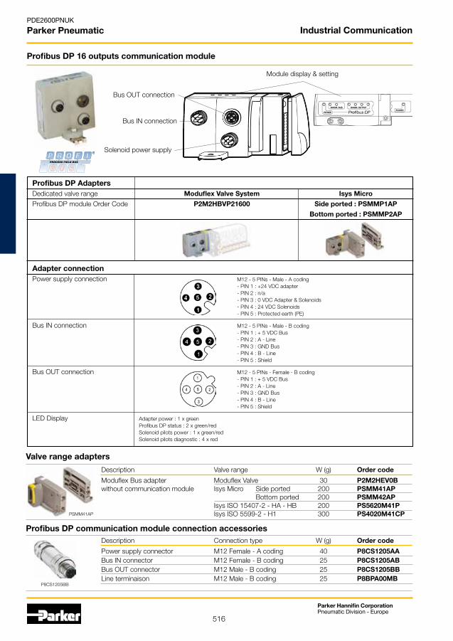
Profibus DP 16 outputs communication module
Bus OUT connection
Module display & setting
Valve range adapters
Description Valve range W (g) Order code
Moduflex Bus adapter Moduflex Valve 30 P2M2HEV0B without communication module Isys Micro Side ported 200 PSMM41AP Bottom ported 200 PSMM42AP Isys ISO 15407-2 - HA - HB 200 PS5620M41P Isys ISO 5599-2 - H1 300 PS4020M41CP
Profibus DP Adapters Dedicated valve range Moduflex Valve System Isys Micro
Profibus DP module Order Code P2M2HBVP21600 Side ported : PSMMP1AP
Bottom ported : PSMMP2AP
Adapter connection Power supply connection M12 - 5 PINs - Male - A coding - PIN 1 : +24 VDC adapter - PIN 2 : n/a - PIN 3 : 0 VDC Adapter & Solenoids - PIN 4 : 24 VDC Solenoids - PIN 5 : Protected earth (PE)
Bus IN connection M12 - 5 PINs - Male - B coding - PIN 1 : + 5 VDC Bus - PIN 2 : A - Line - PIN 3 : GND Bus - PIN 4 : B - Line - PIN 5 : Shield
Bus OUT connection M12 - 5 PINs - Female - B coding - PIN 1 : + 5 VDC Bus - PIN 2 : A - Line - PIN 3 : GND Bus - PIN 4 : B - Line - PIN 5 : Shield
LED Display Adapter power : 1 x green Profibus DP status : 2 x green/red Solenoid pilots power : 1 x green/red Solenoid pilots diagnostic : 4 x red
Bus IN connection
Solenoid power supply
P8MM41AP
Profibus DP communication module connection accessories Description Connection type W (g) Order code
Power supply connector M12 Female - A coding 40 P8CS1205AA Bus IN connector M12 Female - B coding 25 P8CS1205AB Bus OUT connector M12 Male - B coding 25 P8CS1205BB Line terminaison M12 Male - B coding 25 P8BPA00MB
P8CS1205BB
PSMM41AP
Industrial Communication

517
Parker Hannifin CorporationPneumatic Division - Europe
PDE2600PNUK
Parker Pneumatic
InterBus-S 16 outputs communication module
Bus OUT connection
Module display
Valve range adapters
Description Valve range W (g) Order code
Moduflex Bus adapter Moduflex Valve 30 P2M2HEV0B without communication module Isys Micro Side ported 200 PSMM41AP Bottom ported 200 PSMM42AP Isys ISO 15407-2 - HA - HB 200 PS5620M41P Isys ISO 5599-2 - H1 300 PS4020M41CP
InterBus-S Adapters Dedicated valve range Moduflex Valve System
InterBus-S module Order Code P2M2HBVS11600
Adapter connection Power supply connection M12 - 5 PINs - Male - A coding - PIN 1 : +24 VDC adapter - PIN 2 : n/a - PIN 3 : 0 VDC Adapter & Solenoids - PIN 4 : 24 VDC Solenoids - PIN 5 : Protected earth (PE)
Bus IN connection M23 - 9 PINs - Male: - PIN 1 : DO - PIN 6 : n/a - PIN 2 : DO - PIN 7 : n/a - PIN 3 : DI - PIN 8 : n/a - PIN 4 : DI - PIN 9 : n/a - PIN 5 : Ground
Bus OUT connection M23 - 9 PINs - Female: - PIN 1 : DO - PIN 6 : n/a - PIN 2 : DO - PIN 7 : n/a - PIN 3 : DI - PIN 8 : n/a - PIN 4 : DI - PIN 9 : RBST - PIN 5 : Ground
LED Display Adapter power : 1 x green InterBus S status : 3 x green/red Solenoid pilots power : 1 x green/red Solenoid pilots diagnostic : 4 x red
Bus IN connection
Solenoid power supply
P8MM41AP
InterBus-S communication module connection accessories Description Connection type W (g) Order code
Power supply connector M12 Female - A coding 40 P8CS1205AA
P8CS1205AA
Industrial Communication

518
Parker Hannifin CorporationPneumatic Division - Europe
PDE2600PNUK
Parker Pneumatic
AS-i Adapters AS-i module Order Code P2M2HBVA10400 P2M2HBVA10800 P2M2HBVA20600 P2M2HBVA10808A P2M2HBVA20608A P2M2HBVA10404B P2M2HBVA10808B P2M2HBVA20608B AS-i Version V2.0 V2.0 V2.1 V2.0 V2.1 V2.0 V2.0 V2.1 Number of adresses 1 / 31 2 / 31 2 / 31a + 31b 2 / 31 2 / 31a + 31b 1 / 31 2 / 31 2 / 31a + 31b Nb of outputs for sol. valves 4 8 6 8 6 4 8 6 Nb of Inputs - 8 8 4 8 8 Nb of Input connectors - 8 x M8 8 x M8 4 x M12 4 x M12 4 x M12 Input density / connector - 1 1 1 2 2
Adapter connection Yellow cable Bus signal
Bus module and sensors power supply
Black cable 24 VDC outputs for solenoid valves
INPUTS connection M8 - 3 PINs - Female: M12 - 5 PINs - Female:
- PIN 1 : +24 VDC PIN 1: +24 VDC - PIN 1 : +24 VDC
- PIN 3 : Common PIN 2*: Input 2&3 - PIN 2* : Odd Input
- PIN 4 : Input PIN 3: Common - PIN 3 : Common
PIN 4: Input 0 to 3 - PIN 4 : Even Input
PIN 5: n/a - PIN 5 : n/a
*on left connectors only
LED Display Node status : 2 x green/red per node Input status : 4 x yellow per node Valve power (24V from field supply) : 1 x green / red
AS-interface communication module
Input and AS-i status LED display Second node addressing
First node addressing
AS-i Yellow cable
AS-i Black cable
M8 or M12 Input connection
Node addressing connector
Valve range adapters
Description Valve range W (g) Order code
Moduflex Bus adapter Moduflex Valve 30 P2M2HEV0B without communication module Isys Micro Side ported 200 PSMM41AP Bottom ported 200 PSMM42AP Isys ISO 15407-2 - HA - HB 200 PS5620M41P Isys ISO 5599-2 - H1 300 PS4020M41CPP8MM41AP
Connectors for Inputs Description Connection type W (g) Order code
Cable quick connect connector M8 Male 25 P8CS0803J
M12 Male - A coding 25 P8CS1204J
"Y" shape M12 Male - 2 x M12 Female 25 P8CSY1212A
Addressing cable M12 Male - Jack 100 P8LS12JACK
P8CSY1212A
P8CS0803J
Industrial Communication

519
Parker Hannifin CorporationPneumatic Division - Europe
PDE2600PNUK
Parker Pneumatic
Isysnet modules
Isysnet with Isys ISO Valves
Industrial Communication
Dimensions
A B C
102 46 48
D E F
51 22 11
HB-HADimensions
A B E L G
152 137 7,5 106 68
H H1 J K L
8,4 45,8 4 110 16
M P W W1
137 152 40,8 56,8
H1Dimensions
G H H1 J K
56 15,9 15,9 8,5 165
P W
182 49
520
Parker Hannifin CorporationPneumatic Division - Europe
PDE2600PNUK
Parker Pneumatic
Isysnet with Isys Micro Valves
Side ported
Bottom ported
124 a
75
174 + n x 72 + m x 42 12,5
72 61 42 18
71 + m x 42
112
102
144
23
46
133
72
50,8 + n x 72
119.2 50
Note:m=numberofmanifolds(one manifold for 4 valves modules) n=numberofI/Omodules
44 + m x 42
112
22124
75
71 + m x 4250,8 + n x 72
119.2 50
112
144
102
46
133
7261 42 1823
72
174 + n x 72 + m x 42 12,5
M7 fittings a
Ø 4 mm 11
Ø 6 mm 16
Industrial Communication

521
Parker Hannifin CorporationPneumatic Division - Europe
PDE2600PNUK
Parker Pneumatic
Moduflex Bus with Moduflex Valve
AS-i bus islands
Device bus islands
Modulessize 1width : 25 mm
Head and tail pneumatic module setwidth : 48 mm
Modulessize 2width : 37.5 mm
Intermediatemodulewidth :25 mm
Electrical field bus head module width : 62 mm
Electrical field bus head module
Module size 1 2 screws
4 mm dia.surfacemounting
Intermediate module
Module size 2
Tailplate
2 mounting holes 4.3 mm dia
orDIN railmounting
DIN rail 35x7 mm or 35x15 mm
DIN rail 35x7 mm or 35x15 mm
2 pivoting locks for DIN rail mounting
2 mounting holes 4.3 mm dia
2 locks for DIN rail mounting
Pneumatic head module
Island total width depending on valve composition
Industrial Communication

522
Parker Hannifin CorporationPneumatic Division - Europe
PDE2600PNUK
Parker Pneumatic
Moduflex Bus with Isys Micro Valves
Side ported
Bottom ported
124 a
75
142.5 + m x 42 12,5
61 32,5 31 18
58 + m x 42
112
112
124
42
60
52,5
44 + m x 42
112
22124
75142.5 + m x 42 12,5
61 32,5 31 1842
58 + m x 42
112
112
124
60
52,5
Note:m=numberofmanifolds(one manifold for 4 valves modules)
M7 fittings a
Ø 4 mm 11
Ø 6 mm 16
Industrial Communication

523
Parker Hannifin CorporationPneumatic Division - Europe
PDE2600PNUK
Parker Pneumatic
Combinableelements
Subbasemountedelements
Operating information
• Completerange• Standalone,stackableorcombinablemodules• Veryfastresponsetime• Flexibleandhighlymaintainablesystem• DINrailmounting• Ø4mmconnection Working pressure 3 to 8 bar
Working temperature -15 °C to 60 °CFlow(Qmax) 180l/min(PRD=60l/min)ATEXapproval: CEExII2GDc85oC
Step modules Step module subbase
Set of head and tail modulesand deviationmodules
Order code Order code
Line mountedelements
Logic Function Order code
Subbase PSB-A12
Additional interlock PSV-A12
Head&tailset PSE-A12
Deviationstandard PSD-A12
Deviationforremote PSD-B12
AND PLL-A11 OR PLK-A11
CliponDin-rail PZM-L199
B
RP
A
B
A
S
ba
&
S
ba
1 &
S
a
S
a
1 &
S
a
S
a
&
S
ba
S
ba
1 &
S
ba
Order code
Pressure switchTo be used with3 port subbase
With subbase PRE-A12
Without subbase PRE-A10
a
A B
a
S
Pp
Logic sequencer
Logic Function Order code
AND PLL-B12 OR PLK-B12 NOT PLN-B12 INPUT PLE-B12
Logic Function Order code
AND PLL-C10 NOT inhibit standard PLN-C10 NOT inhibit threshold PLN-D10 OR PLK-C10 YESregenerated PLJ-C10
3 port subbase to be ordered separately.Logic relays
Amplifier relaysTo be used with4 port subbase
Memory relaysTo be used with4 port subbase
Logic elements
Order code
Without sub base PSM-A10Pneumatic output
Visual indication of pneumatic PSM-A12output and manual override
With sub base PSM-B12Wihtout manual overide
Order code
With subbase PLM-A12
Without subbase PLM-A10
Order code
With subbase PRD-A12
Without subbase PRD-A10
Order code
Sensor relays
With subbase PRF-A12
Without subbase PRF-A10
S
a
Miniature high-speed valves in stand alone, stackable or combined modules, incorporating standard logic functions. The range also includes timers and impulse modules.
Logic Processing
For ATEX specific productscontact Sales Office
For more information see www.parker.com/euro_pneumatic
524
Parker Hannifin CorporationPneumatic Division - Europe
PDE2600PNUK
Parker Pneumatic
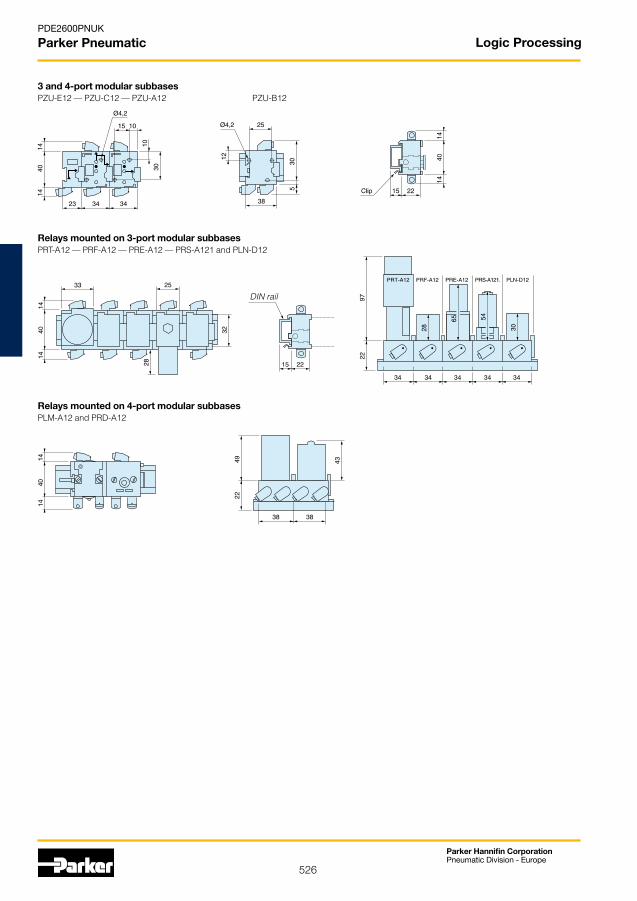
Subbase for logic elements and relays
Order code
Input module PZU-E12 3port"commoninput" PZU-A12 3port"cascade" PZU-C12 4 port subbase* PZU-B12
3 port and 4 port subbases
* For combination with memory relay and amplified relay.
a
S
01t
Time delay relays
Function Timing Order code
Output 0,1 to 3s PRT-E10after timed 0,1 to 30s PRT-A10period 10 to 180s PRT-B10
With subbase 0,1 to 30s PRT-A12
Output 0,1 to 3s PRT-F10during 0,1 to 30s PRT-C10timed 10 to 180s PRT-D10period
To be mounted on 3 port subbase
Logic Processing

525
Parker Hannifin CorporationPneumatic Division - Europe
PDE2600PNUK
Parker Pneumatic
Ø6 mm push-in connections Ø4 mm push-in connections
DIN rail
DIN rail
Clip
Pressure indicator
Ø4 mm push-in connections
Dimensions, Logic processing
Modular sequencer
Line mounted logic elements PLL-A11andPLK-A11
Combinable logic elementsPLE-B12—PLL-B12—PLK-B12andPLN-B12
Logic elements mounted on 3-port modular subbasesPZU-E12 PLJ-C10—PLN-C10—PLK-C10andPLL-C10mountedon PZU-C12 and PZU-A12
Logic Processing
526
Parker Hannifin CorporationPneumatic Division - Europe
PDE2600PNUK
Parker Pneumatic
DIN rail
3 and 4-port modular subbasesPZU-E12—PZU-C12—PZU-A12 PZU-B12
Relays mounted on 3-port modular subbasesPRT-A12—PRF-A12—PRE-A12—PRS-A121andPLN-D12
Relays mounted on 4-port modular subbasesPLM-A12andPRD-A12
Logic Processing
527
Parker Hannifin CorporationPneumatic Division - Europe
PDE2600PNUK
Parker Pneumatic
Ø4 mm push-in connections
Ø4 mm push-in connections
Ø4 mm push-in connections
Totalising countersPCT-A11 PCT-B11
Digital display timersPCM-A11 to PCM-B11
Timers with calibrated dialPCM-F11 and PCM-G11
Logic Processing

528
Parker Hannifin CorporationPneumatic Division - Europe
PDE2600PNUK
Parker Pneumatic
Symbol Flow Order code
Spring return push buttons
60 l/min PXB-B3111BA2
240 l/min PXB-B4131BA2
Symbol Flow Order code
60 l/min PXB-B3111BA3
240 l/min PXB-B4131BA3
Green - With 1 NC valve
Symbol Flow Order code
60 l/min PXB-B3111BA4
240 l/min PXB-B4131BA4
Red - With 1 NC valve
Symbol Flow Order code
Mushroom head push buttons
60 l/min PXB-B3111BC2
240 l/min PXB-B4131BC2 Black - Spring return - With 1 NC valve
Symbol Flow Order code
60 l/min PXB-B3111BT4
240 l/min PXB-B4131BT4
Red-Latching-With1NCvalve
Symbol Flow Order code
60 l/min PXB-B3111BD2 240 l/min PXB-B4131BD2 Black - 2 positions - With 1 NC valve
Selector switches
Operating information
• Faciamountedoperation
• 3/2NOorNC
• Modularconstruction
• Widerangeofactuators
• Dualpneumaticanelectricaloutputsignal
Working pressure PXB-B3•• 1to9barPXB-B4•• 1to10barPXV-•• 1to8barWorking temperature -15°C to +60°CATEXapproval: CEExII3GD
Push button valves - Visual indicators
Black - With 1 NC valve
Flow characteristics
PXB-B3•• Qmax=60l/min Qn=30l/minPXB-B4•• Qmax=240l/min Qn=120l/min
Connections Ø 4 mm push-in
DesignedtofitthestandardelectricalØ22mmknock out, they can provide dual pneumatic and electrical output signals. A variety of button and switch actuators are available.
Control and process duty Ø 22 mm - PXB
For ATEX specific productscontact Sales Office
529
Parker Hannifin CorporationPneumatic Division - Europe
PDE2600PNUK
Parker Pneumatic
Black ZB4-BA2
Green ZB4-BA3
Red ZB4-BA4
Black ZB4-BC2
Green ZB4-BC3
Red ZB4-BC4
2 positions fixed ZB4-BD2
3 positions fixed ZB4-BD3
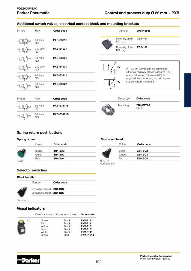
Normally open ZBE-101 NO Normally closed ZBE-102 NC
Mounting ZB4-BZ009 block
60 l/min PXB-B3911 NC 240 l/min PXB-B4931 NC
60 l/min PXB-B3111B NC 60 l/min PXB-B3121B NO
60 l/min PXB-B3921 NO 240 l/min PXB-B4931 NO 60 l/min PXB-B3912 NC 60 l/min PXB-B3922 NO
Spring return push buttons
Colour Order code
Spring return
Colour Order code
Mushroom head
Black handle
Function Order code
Visual indicators
Colour actuated Colour unactuated Order code
Green Black PXV-F131 Red Black PXV-F141 Yellow Black PXV-F151 Blue Black PXV-F161 White Black PXV-F111 Green Red PXV-F1314
Flush Ø40 mm spring return
Standard
Symbol Flow Order code
Additional switch valves, electrical contact block and mounting brackets
Contact Order code
Description Order code
Selector switches
Symbol Flow Order code
All PXB-B4 valves can be connected either as normally closed 3/2 valve (NC) or normally open 3/2 valve (NO) as required,byconnectingtheprimaryairsupply to port 1 or port 3.
Control and process duty Ø 22 mm - PXB

530
Parker Hannifin CorporationPneumatic Division - Europe
PDE2600PNUK
Parker Pneumatic
PXB-B3
PXB-B4
46,5
49,5*
1,6
51
59,5
1,6
65,5
46,2
1,6 30
40
56
751,6
Ø 22,2 UTEØ22,5DIN
Body width 30mm* With2x4mmtube=10 With2,7x4mmtube=15
Body width 30mm* With2x4mmtube=10 With2,7x4mmtube=15
*
Control and process duty Ø 22 mm - PXB
531
Parker Hannifin CorporationPneumatic Division - Europe
PDE2600PNUK
Parker Pneumatic
Symbol Actuator Return Operating forces Order code at 6 bar, N
Steel Spring 24 PXC-M601A110 plunger
Steel roller Spring 24 PXC-M601A102 plunger
90O Steel roller Spring 24 PXC-M601A103 plunger
Symbol Actuator Return Operating forces Order code at 6 bar, N
Steel plunger Spring 11 PXC-M111
Symbol Actuator Return Operating forces Order code at 6 bar, N
Plastic roller Spring 4,5 PXC-M121
Steel roller Spring 4,5 PXC-M131
Symbol Actuator Return Operating forces Order code at 6 bar, N
Plastic roller Spring 7 PXC-M521
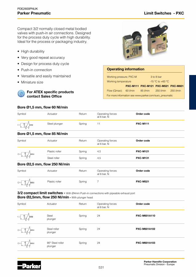
Limit Switches - PXC
Operating information
• Highdurability
• Verygoodrepeataccuracy
• Designforprocessdutycycle
• Push-inconnection
• Versatileandeasilymaintained
• Miniaturesize
Working pressure; PXC-M 3 to 8 bar
Working temperature -15 °C to +60 °C
PXC-M111 PXC-M121 PXC-M521 PXC-M601
Flow (Qmax): 60 l/min 85 l/min 250 l/min 250 l/min
Bore Ø2,5 mm, flow 250 Nl/min
Bore Ø1,5 mm, flow 85 Nl/min
Bore Ø1,5 mm, flow 60 Nl/min
3/2 compact limit switches - With Ø4mm Push-in connections with pipeable exhaust port
Bore Ø2,5mm, flow 250 NI/min - With plunger head
Compact 3/2 normally closed metal bodied valveswithpush-inairconnections.Designedfor the process duty cycle with high durability. Ideal for the process or packaging industry.
For ATEX specific productscontact Sales Office For more information see www.parker.com/euro_pneumatic

532
Parker Hannifin CorporationPneumatic Division - Europe
PDE2600PNUK
Parker Pneumatic Limit Switches - PXC
Dimensions, Limit switches, Series PXC
All dimensions in mm unless otherwise stated
3/2 miniature limit switches
PXC-M111 PXC-Z12 PXC-Z11
PXC-M121 - PXC-M131 PXC-M521
3/2 compact limit switches
PXC-M601A102 PXC-M601A103
PXC-M601A110
533
Parker Hannifin CorporationPneumatic Division - Europe
PDE2600PNUK
Parker Pneumatic
Control module only
Symbol Connections Order code
Ø4 mm PXP-A11 Push-in
Complete unitsPolymer enclosure, with two Ø40 mm push button with protective guards and control module
Symbol Connections Number of Order code control modules Ø4 mm 1 PXP-C111 Push-in
Ø4 mm 2 PXP-D121 Push-in
Metal enclosure, with two Ø60 push buttons, wrist restbar, built in protective guard and control module
Symbol Connections Number of Order code control modules
Push-in 1 PXP-S111 Ø6 mm for supply Ø4 mm for output
Push-in 2 PXP-S121 Ø6 mm for supply Ø4 mm for output
Operating information
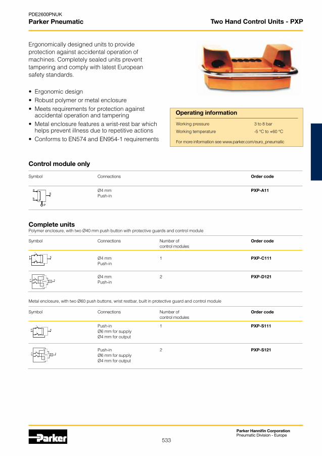
• Ergonomicdesign• Robustpolymerormetalenclosure• Meetsrequirementsforprotectionagainst
accidental operation and tampering• Metalenclosurefeaturesawrist-restbarwhich
helps prevent illness due to repetitive actions• ConformstoEN574andEN954-1requirements
Working pressure 3 to 8 bar
Working temperature -5 °C to +60 °C
Ergonomically designed units to provide protection against accidental operation of machines. Completely sealed units prevent tampering and comply with latest Europeansafety standards.
Two Hand Control Units - PXP
For more information see www.parker.com/euro_pneumatic

534
Parker Hannifin CorporationPneumatic Division - Europe
PDE2600PNUK
Parker Pneumatic
* Ø4 mm push-in connections** Ø6 mm push-in connections
PXP-A11 PXP-C111 and PXP-D121 PXP-S111 and PXP-S121
Dimensions
Two Hand Control Units - PXP
535
Parker Hannifin CorporationPneumatic Division - Europe
PDE2600PNUK
Parker Pneumatic
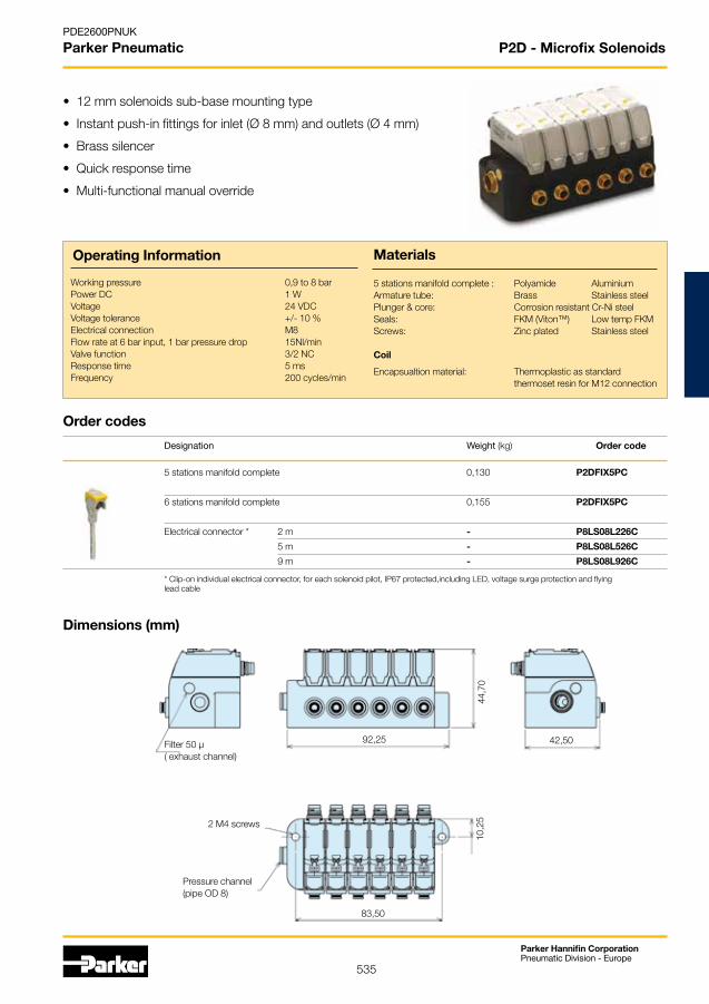
• 12mmsolenoidssub-basemountingtype
• Instantpush-infittingsforinlet(Ø8mm)andoutlets(Ø4mm)
• Brasssilencer
• Quickresponsetime
• Multi-functionalmanualoverride
Working pressure 0,9 to 8 bar Power DC 1 WVoltage 24 VDC Voltage tolerance +/- 10 %Electrical connection M8Flow rate at 6 bar input, 1 bar pressure drop 15Nl/min Valve function 3/2 NC Response time 5 ms Frequency 200 cycles/min
Operating Information
5 stations manifold complete : Polyamide Aluminium Armature tube: Brass Stainless steel Plunger & core: Corrosion resistant Cr-Ni steel Seals: FKM (Viton™) Low temp FKMScrews: Zinc plated Stainless steel
Coil
Encapsualtion material: Thermoplastic as standard thermoset resin for M12 connection
Designation Weight (kg) Order code
5 stations manifold complete 0,130 P2DFIX5PC
6 stations manifold complete 0,155 P2DFIX5PC
Electrical connector * 2 m - P8LS08L226C
5 m - P8LS08L526C
9 m - P8LS08L926C
Order codes
Dimensions (mm)
Materials
Filter 50 µ( exhaust channel)
92,25 42,50
83,50
2 M4 screws
Pressure channel(pipe OD 8)
10,2
544
,70
* Clip-on individual electrical connector, for each solenoid pilot, IP67 protected,including LED, voltage surge protection and flying lead cable
P2D - Microfix Solenoids

536
Parker Hannifin CorporationPneumatic Division - Europe
PDE2600PNUK
Parker Pneumatic
Solenoid operators - 15 mm
High reliabilityFew moving parts result in high reliability, rapid changeover and very long life.
Low power demandThe solenoids have a power demand of 1.2 W at 24 VDC and 1.6 VA at 24 VAC, 115 V AC and 230 VAC.
High protection classThe protection class is IP 67 when connected using the cable plug with a moulded cable. When using the standard cable plug for fitting by the user, the protection class is IP65, the valve, with Fast-on connectors, has an encapsulation class of IP 20.
Insensitive to dirty airThe use of generously sized flow paths (1.0 mm diameter) means that the valve can be used in normal industrial environments without problems of blocking.
Manual override as optionThe operators can be supplied with our without manual override. The manual override device is available as a screwdriver groove or with a control arm, and is either spring return (blue) or lockable (yellow).
The P2E- •V solenoid operator rangeTheP2E-•Vrangeofoperatorsarenormallyclosed(NC)3/2solenoid valves, with exceedingly compact dimensions in relation to their capacity.
International standardThe port connection pattern complies with a new French CNOMO standard (in process of drafting), with cable plug connections in accordance with DIN 43650 Form C.
Compact designOveralldimensionsoftheP2E-•Voperatorsaresubstantiallyless than those of earlier generations of solenoid operators.
High flow capacityHigh flow capacity relative to the electrical operating power as a result of optimised internal flow paths.
Corrosion-resistant designThe valve is made of thermoplastic material and stainless steel, with Viton™ and nitrile rubber seals for excellent corrosion resistance.
Clean lines suitable for food industry applications, P2E-QVThe valve has been designed in conjunction with several machine manufacturers and organisations in the food processing industry, with corrosion-resistant materials and smooth lines being important starting points. The valve and its accessories have been designed so that there are no gaps or crevices in which dirt could collect.
Cable plugs and connectors are available in several variants.
High electric protection class: IP65 or IP67.
Terminal layout to DIN 43650 Form C.
Smooth casing, suitable for food industry applications.
High flow rate, long life.
Corrosion-resistant materials.
P2E-•V - Solenoid Operators 15mm
537
Parker Hannifin CorporationPneumatic Division - Europe
PDE2600PNUK
Parker Pneumatic
Order key, solenoid operators (15mm)
P 2 E - Q V C 323
Overriders
0 Without
1 Non locking (blue)
2 Locking (yellow)
3 Extended non locking (blue)
4 Extended locking (yellow)
Voltage
B 12 V
C 24 V
D 48 V
F 115 V*
J 230 V*
W 37,5 V**
T 72 V**
Y 78 V**
V 96 V**
E 110 V**
Valve family
P2E Solenoid operator
Subfamily
Solenoid operator, 15 mm wide Electric connection acc. to ISO 15217 Form C El/supply connection on opposite side
K Standard version
M Mobile version
Q Food industry version
H Hight flow
Type of current
1 AC 50 Hz
2 DC
4 AC 50/60 Hz
5 Mobile and wide band only
Valve type / Function
3 3/2 valve,normally closed (NC)
1 3/2 valve,normally opened (NO) * For standard and food type only** For mobile "M" version only
Materials
NC, Standard NC, Food1) NC, Mobile2) NC, Hight flow
Working pressure 0 to10 bar 0 to 10 bar 0 to 10 bar 0 to 10 barWorking temperature -15 °C to +60 °C -15 °C to +60 °C -40 °C to +70 °C -15 °C to +50 °COrifice 1,0 mm 1,0 mm 1,0 mm 1,4 mmFlowQmax 33Nl/min 33Nl/min 22Nl/min 50Nl/minPower, hold DC 1,2 W / AC 1,6 VA * DC 1,2 W / AC 1,6 VA * DC 1,4 W DC 1,8 W / AC 2,4 VAPower, surge DC 1,2 W / AC 3,5 VA * DC 1,2 W / AC 3,5 VA * DC 1,4 W DC 1,8 W / AC 5,5 VAConnection time 100% 100% 100% 100%Voltage tolerance +10%/–15% +10%/–15% +25%/–30% +10%/–15%Electric connection: DIN 43650 Form CPort pattern: To future CNOMO standardProtection: IP 65Approval: Standard solenoids are UL 429 recognized and marked with the following symbol .Working media: All neutral media, such as compressed air, water, hydraulic oil and many gases.1) Design: Completely smooth exterior, suitable for food industry.2) Mobile standard According to European standard EN 50 155.
Technical data
Transients
Interrupting the current through the solenoid coil produces momentary voltage peaks which, under unfavourable conditions, can amount to several hundred times the rated operating voltage. Normally, these transients do not cause problems, but to achieve the maximum life of relays in the circuit (and particularly of transistors, thyristors and integrated circuits) it is desirable to provide protection by means of voltage-dependent resistors (varistors). All cable plugs with a yellow LED also incorporate such protection.
Service life
With compressed air at 6 bar, 20 °C and complying with the requirements for compressed air quality as set out in ISO8573-1 norm (class 4 for dry and class 5 for filtered air), the valves should have a life of at least 50 million cycles.
Operator
Body, coil casing Thermoplastic Internal metal parts Steel Screws Stainless steel Bottom plug Thermoplastic Sealing materials FPM (Viton™) and nitrile rubber
Cable head
Sheath Thermoplastic Retaining screw Stainless steel, zinc-plated steel
* Power , hold for 230VAC 2.4VA Power, surge for 230VAC 5.5VA
P2E-•V - Solenoid Operators 15mm
538
Parker Hannifin CorporationPneumatic Division - Europe
PDE2600PNUK
Parker Pneumatic
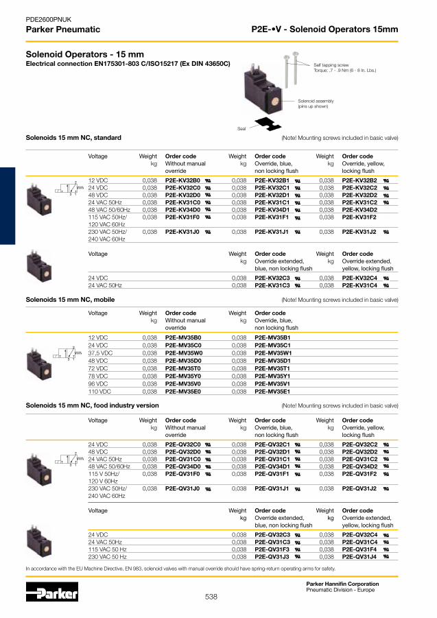
Solenoid Operators - 15 mmElectrical connection EN175301-803 C/ISO15217 (Ex DIN 43650C)
Solenoids 15 mm NC, mobile (Note! Mounting screws included in basic valve)
Voltage Weight Order code Weight Order code kg Without manual kg Override, blue, override non locking flush
12 VDC 0,038 P2E-MV35B0 0,038 P2E-MV35B1 24 VDC 0,038 P2E-MV35C0 0,038 P2E-MV35C1 37,5 VDC 0,038 P2E-MV35W0 0,038 P2E-MV35W1 48 VDC 0,038 P2E-MV35D0 0,038 P2E-MV35D1 72 VDC 0,038 P2E-MV35T0 0,038 P2E-MV35T1 78 VDC 0,038 P2E-MV35Y0 0,038 P2E-MV35Y1 96 VDC 0,038 P2E-MV35V0 0,038 P2E-MV35V1 110 VDC 0,038 P2E-MV35E0 0,038 P2E-MV35E1
In accordance with the EU Machine Directive, EN 983, solenoid valves with manual override should have spring-return operating arms for safety.
Self tapping screwTorque: .7 - .9 Nm (6 - 8 In. Lbs.)
Solenoid assembly(pins up shown)
Seal
Solenoids 15 mm NC, food industry version (Note! Mounting screws included in basic valve)
Voltage Weight Order code Weight Order code Weight Order code kg Without manual kg Override, blue, kg Override, yellow, override non locking flush locking flush
24 VDC 0,038 P2E-QV32C0 0,038 P2E-QV32C1 0,038 P2E-QV32C2 48 VDC 0,038 P2E-QV32D0 0,038 P2E-QV32D1 0,038 P2E-QV32D2 24 VAC 50Hz 0,038 P2E-QV31C0 0,038 P2E-QV31C1 0,038 P2E-QV31C2 48 VAC 50/60Hz 0,038 P2E-QV34D0 0,038 P2E-QV34D1 0,038 P2E-QV34D2 115 V 50Hz/ 0,038 P2E-QV31F0 0,038 P2E-QV31F1 0,038 P2E-QV31F2 120 V 60Hz 230 VAC 50Hz/ 0,038 P2E-QV31J0 0,038 P2E-QV31J1 0,038 P2E-QV31J2 240 VAC 60Hz
Voltage Weight Order code Weight Order code kg Override extended, kg Override extended, blue, non locking flush yellow, locking flush
24 VDC 0,038 P2E-QV32C3 0,038 P2E-QV32C4 24 VAC 50Hz 0,038 P2E-QV31C3 0,038 P2E-QV31C4 115 VAC 50 Hz 0,038 P2E-QV31F3 0,038 P2E-QV31F4 230 VAC 50 Hz 0,038 P2E-QV31J3 0,038 P2E-QV31J4
Solenoids 15 mm NC, standard (Note! Mounting screws included in basic valve)
Voltage Weight Order code Weight Order code Weight Order code kg Without manual kg Override, blue, kg Override, yellow, override non locking flush locking flush
12 VDC 0,038 P2E-KV32B0 0,038 P2E-KV32B1 0,038 P2E-KV32B2 24 VDC 0,038 P2E-KV32C0 0,038 P2E-KV32C1 0,038 P2E-KV32C2 48 VDC 0,038 P2E-KV32D0 0,038 P2E-KV32D1 0,038 P2E-KV32D2 24 VAC 50Hz 0,038 P2E-KV31C0 0,038 P2E-KV31C1 0,038 P2E-KV31C2 48 VAC 50/60Hz 0,038 P2E-KV34D0 0,038 P2E-KV34D1 0,038 P2E-KV34D2 115 VAC 50Hz/ 0,038 P2E-KV31F0 0,038 P2E-KV31F1 0,038 P2E-KV31F2 120 VAC 60Hz 230 VAC 50Hz/ 0,038 P2E-KV31J0 0,038 P2E-KV31J1 0,038 P2E-KV31J2 240 VAC 60Hz Voltage Weight Order code Weight Order code kg Override extended, kg Override extended, blue, non locking flush yellow, locking flush
24 VDC 0,038 P2E-KV32C3 0,038 P2E-KV32C4 24 VAC 50Hz 0,038 P2E-KV31C3 0,038 P2E-KV31C4
P2E-•V - Solenoid Operators 15mm

539
Parker Hannifin CorporationPneumatic Division - Europe
PDE2600PNUK
Parker Pneumatic
General application valves for dry or lubricated air, neutral gases and liquids
2/2-Way Direct Operated Valve
Description: • 2/2-Way Direct Operated Valve - Normally Closed. • Coil IP65 for 2 P + E plug according to DIN 43650 type A • Power Consumption 8W (AC), 9W (DC).
Applications: • Shut-off and control (On-Off) of water, air, light oils, steam and inert gases • Humidifiers, welding systems, industrial washing machines, automatic dispensers, diesel oil burners, sterilizers, compressors. Temperature Range: • Min: -10°C l Max: see table Seals Material: • See tableAdvantages: • Versatile product for many 2/2 NC valve requiring applications, robust design.
** Manual override standard
Port Admissible differential Fluid Seal Reference size Orifice K V pressure (bar) Temp. Material number Options G mm l/min Min. Max. Max. C° Valve Housing Coil DC AC
2/2-Way Direct Operated Valve Normally CLOsED
Fluid Controls
1/8” 2.5 3.50 0 10.0 28.0 100°C Ruby E121K23 2995 481865 -1/8” 3.0 4.50 0 7.0 10.0 100°C FKM 121K1302 2995 481865 -1/4” 1.2 0.85 0 36.0 80.0 100°C Ruby E121K65 2995 481865 -1/4” 1.5 1.50 0 25.0 60.0 75°C PCTFE E121K04 2995 481865 -1/4” 1.5 1.50 0 25.0 60.0 100°C Ruby E121K67 2995 481865 -1/4” 1.5 1.50 0 20.0 20.0 100°C FKM E121K0402 2995 481865 -1/4” 2.5 3.50 0 10.0 28.0 75°C PCTFE E121K07 2995 481865 -1/4” 2.5 3.50 0 7.0 14.0 100°C FKM 121K0706 2995 481865 -1/4” 2.5 3.50 0 10.0 28.0 100°C Ruby E121K63 2995 481865 -1/4” 3.0 4.50 0 7.0 20.0 75°C PCTFE E121K03 2995 481865 -1/4” 3.0 4.50 0 7.0 10.0 100°C FKM E121K0302 2995 481865 -1/4” 3.0 4.50 0 7.0 10.0 100°C EPDM 121K0323 2995 481865 -1/4” 3.0 4.50 0 7.0 10.0 100°C FKM E121K0352 2995 481865 **1/4” 3.0 4.50 0 7.0 20.0 100°C Ruby E121K64 2995 481865 -1/4” 4.0 7.50 0 4.0 10.0 100°C FKM 121K02 2995 481865 -1/4” 4.0 7.50 0 4.0 10.0 100°C FKM 121K0250 2995 481865 **1/4” 5.0 11.00 0 2.0 7.0 100°C FKM 121K01 2995 481865 -1/4” 5.0 11.00 0 2.0 7.0 100°C EPDM 121K0103 2995 481865 -1/4” 5.0 11.00 0 2.0 7.0 100°C FKM 121K0150 2995 481865 **1/4” 5.0 11.00 0 2.0 7.0 100°C FKM 121K3106 2995 481865 -3/8” 4.0 7.50 0 4.0 10.0 100°C FKM 121K3206 2995 481865 -3/8” 6.0 12.00 0 1.1 5.0 100°C FKM 121K3303 2995 481865 -3/8” 6.0 12.00 0 1.1 5.0 100°C FKM 121K3306 2995 481865 -1/2” 8.5 25.00 0 0.5 1.1 100°C FKM E121K46 2995 481865 -1/2” 11.0 36.00 0 0.3 0.7 100°C FKM E121K45 2995 481865 -

540
Parker Hannifin CorporationPneumatic Division - Europe
PDE2600PNUK
Parker Pneumatic
2/2 & 3/2 Solenoid Valves for High Pressure pneumatic applications - 40 bar
Product offering:
• 2/2 valves and 3/2 way valves - pilot operated
• Pipe mounting (G 1/2- 3/4) or sub-base mounting
• 1.5 (2) - 40 bar
• Normally open or closed
• Internal or external pilot pressure supply
Customer Value Proposition:
• Safety of operation
• Reliability
• Response time stability
• Repeatability
• No leakage
• Integrated non return valve (421version)
The use of high pressure gases became a necessity in the new technologies developed during the last years.
The control of these fluids can be done through the solenoid valves specially designed by Parker Lucifer for high pressure applications (maximum 50 bar).
The life expectancy of several millions of cycles, with response time of few milliseconds, allows the use of these valves on intensive applications and on high technology machines, as the plastic bottle blowing machines, or the laser cutting machines.
Parker Lucifer also develops special valves or adapted blocks upon specific customers needs. Please contact your agent for more information.
Fluid Controls
541
Parker Hannifin CorporationPneumatic Division - Europe
PDE2600PNUK
Parker Pneumatic
Application Example
Function 2/2 pilot operated: Normally closed (with internal pilot pressure) 321H/F type Normally closed (with external pilot pressure) 421H/F type Normally open (with internal pilot pressure) 322H/F type
3/2 pilot operated: normally closed (with internal pressure) 331B typeISO diagram 321H/F 322H/F 421H/F 331B
Mounting - For direct pipe mounting G 1/2" or 3/4" (2/2 Valve type H); G 1/4 (3/2 Valve type B) - For sub-base mounting (type F)Nominal diameter 15 mm (type H), 14 mm (type F)Pressures For the version with external pilot pressure, the pilot pressure must always be higher than the controlled pressureExternal Leakage 0 Ncc/min.Internal Leakage < 20 Ncc/min.Fluids Dry lubricated or non lubricated air, Argon, Nitrogen. Oxygen on requestProof pressure 200 barFiltration < 1 µmLife expectancy > 2 106 cycles (dry and clean air) > 8 106 cycles (lubricated air)Temperatures Ambient / fluid mini: -10 °C Ambient / fluid maxi: +50 °CMaterials specifications Body/cover: 2/2 Valves: Brass - 3/2 Valves: Aluminium Pilot seals : PUR Main seals : FKM (Viton®) with isolating diaphragm from PUR Tube and plunger : Stainless steel Coil : Encapsulation from PA66 + 30% fiber glassOptions ∆p maxi 50 bar on requestResponse Time Depends on applicationMounting Position IndifferentSpecials Parker Lucifer also develops special valves or adapted blocks upon specific customers needs. Please contact your agent for more information.
Main Technical Specifications
Fluid Controls
542
Parker Hannifin CorporationPneumatic Division - Europe
PDE2600PNUK
Parker Pneumatic
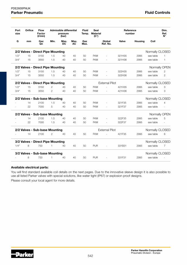
Available electrical parts:You will find standard available coil details on the next pages. Due to the innovative sleeve design it is also possible to use all listed Parker valves with special solutions, like water tight (IP67) or explosion proof designs.
Please consult your local agent for more details.
Port Orifice Flow Admissible differential Fluid Seal Reference Dim. size Factor pressure Temp. Material number Ref. (l/min) (bar) (C°) N°
G mm Gaz Min. Max. Max. Gaz Global Valve Housing Coil Qn DC AC Max. Ref. No.
Fluid Controls
2/2 Valves - Direct Pipe Mounting Normally CLOSED 1/2” 15 3150 1.5 40 40 50 FKM - 321H35 2995 see table 1
3/4” 15 3550 1.5 40 40 50 FKM - 321H36 2995 see table 1
2/2 Valves - Direct Pipe Mounting Normally OPEN 1/2” 15 3150 1.5 40 40 50 FKM - 322H35 2995 see table 2
3/4” 15 3550 1.5 40 40 50 FKM - 322H36 2995 see table 2
2/2 Valves - Direct Pipe Mounting External Pilot Normally CLOSED 1/2” 15 3150 2 40 40 50 FKM - 421H35 2995 see table 3
3/4” 15 3550 2 40 40 50 FKM - 421H36 2995 see table 3
2/2 Valves - Sub-base Mounting Normally CLOSED - 14 2100 1.5 40 40 50 FKM - 321F35 2995 see table 4
- 22 7000 5 40 40 50 FKM - 321F37 2995 see table -
2/2 Valves - Sub-base Mounting Normally OPEN - 14 2100 1.5 40 40 50 FKM - 322F35 2995 see table 5
- 22 7000 1.5 40 40 50 FKM - 322F37 2995 see table -
2/2 Valves - Sub-base Mounting External Pilot Normally CLOSED- 14 2100 2 40 40 50 FKM - 421F35 2995 see table 6
3/2 Valves - Direct Pipe Mounting Normally CLOSED
1/4” 8 750 1 40 40 50 PUR - 331B31 2995 see table 7
3/2 Valves - Sub-base Mounting Normally CLOSED
- 8 750 1 40 40 50 PUR - 331F31 2995 see table -

543
Parker Hannifin CorporationPneumatic Division - Europe
PDE2600PNUK
Parker Pneumatic
Dimensions
A B C D E
G3/4" 80 32 53 17.5 G1/2" 75 27 53 13.5
Dimensions Reference N° 1 Dimensions Reference N° 2
Dimensions Reference N° 3
Dimensions Reference N° 4 Dimensions Reference N° 5
Dimensions Reference N° 7Dimensions Reference N° 6
Fluid Controls

544
Parker Hannifin CorporationPneumatic Division - Europe
PDE2600PNUK
Parker Pneumatic
18.8
37,5
20
32
24
35.5 19.5
32 mm Electrical Parts Availability
481865 Series - Standard Coil Mono-Frequency, F Class, IP65
Encapsulated in synthetic material, connector for 2P+E DIN 43650 A Plug, IP65 insulation class to be considered with connector plug only. This coil conforms to the IEC/CENELEC safety standards and complies with European low-voltage directive 73/23/EC.
Electrical Parts Availability
Dimensional Drawing N° 8
Voltage Power Reference Approvals Ambient Class Dimensional V Consumption Temperature of insulation Drawing
24/50 8 W 481865A2 - -40°C to +50°C F Class 155°C 8
48/50 8 W 481865A4 - -40°C to +50°C F Class 155°C 8
110/50 8 W 481865A5 - -40°C to +50°C F Class 155°C 8
220-230/50 8 W 4818653D - -40°C to +50°C F Class 155°C 8
380/50 8 W 481865A9 - -40°C to +50°C F Class 155°C 8
24/60 8 W 481865B2 - -40°C to +50°C F Class 155°C 8
230/60 8 W 481865J3 - -40°C to +50°C F Class 155°C 8
115/60 8 W 481865K8 - -40°C to +50°C F Class 155°C 8
12 DC 9 W 481865C1 - -40°C to +50°C F Class 155°C 8
24 DC 9 W 481865C2 - -40°C to +50°C F Class 155°C 8
48 DC 9 W 481865C4 - -40°C to +50°C F Class 155°C 8
110V DC 9 W 481865C5 - -40°C to +50°C F Class 155°C 8
All dimensions are in mm
Fluid Controls
545
Parker Hannifin CorporationPneumatic Division - Europe
PDE2600PNUK
Parker Pneumatic
18.8
37,5
20
32
24
35.5 19.5
32 mm Electrical Parts Availability
483510 Series - Standard Bi-Frequency Coil, F Class, IP65
Encapsulated in synthetic material, connector for 2P+E DIN 43650 A Plug, IP65 insulation class to be considered with connector plug only.
This coil conforms to the IEC/CENELEC safety standards and complies with European low-voltage directive 73/23/EC.
VoltageTolerances: -10% to +10% of the nominal voltage (AC), -5% to +10% of the nominal voltage (DC)
Duty Continuous duty coil (100%ED)
Weight: 130 g (without plug)
Dimensional Drawing N° 8
Voltage Power Reference Approvals Ambient Class Dimensional V Consumption Temperature of insulation Drawing
12/50-60 9 W 4835101W - -40°C to +50°C F Class 155°C 8
24/50-60 9 W 483510P0 - -40°C to +50°C F Class 155°C 8
48/50-60 9 W 483510S4 - -40°C to +50°C F Class 155°C 8
110-115/50 120/60 9 W 483510S5 - -40°C to +50°C F Class 155°C 8
220-240/50 240/60 9 W 483510S6 - -40°C to +50°C F Class 155°C 8
All dimensions are in mm
Fluid Controls

546
Parker Hannifin CorporationPneumatic Division - Europe
PDE2600PNUK
Parker Pneumatic
Technical Data
Function: 2/2 solenoid valve closed when de-energized.
Design: Pilot operated poppet valve with magnalift.
Mounting: For direct pipe mounting or with the help of M5x6 mm screw (see dimensions).
Mounting position: Indifferent.
Material specifications: Forged brass body. Internal parts in stainless steel. sealing material in PUR.
Range of admissible ∆p min. = 0 barpressure drop: ∆p max. = 7 bar
Response time (see p. 2): Conditions: voltage 24 VDC nominal, flow 34 Nm3/h. Reference pressure dynamic (orifice 2): 4.5 bar. Response times are increasing above starting from 300 millions cycles.
Switching on: TE on: 9.5 - 12 ms Electrical response time until the plunger is in fully attracted position. T on: 10-14 ms Filling time until the pressure has reached 50% of output pressure P2 (own volume of the valve, outlet port plugged.)
Switching off: TD off: 4 - 8 ms Closing time until the plunger is in the rest position. T off: 5,5 - 9,5 ms Emptying time until the pressure has dropped to 50% of P2 pressure. This response time is depending on user at the outlet port.
Cycling rate: Up to 30 Hz.
Life expectancy: > 500 millions cycles Conditions: Instrumentation dryed and filtered air at 20 µm, (dew point +2°C). P max. 5 bar nominal voltage 24 VDC vibrations 5 to 500 Hz.
Media: Instrumentation air (dryed and unlubricated) filtered at 20 µm.
Fluid temperature: Min. 0°C. Max. + 40°C.
Ambient temperature: 0°C to +50°C.
Vibrations: Up to 1500 Hz, max. shocks 10 g. At max. vibration rating, life expectancy will decrease.
Electrical part: 32 mm coil 483816 (14W DC) encapsulated in synthetic material. Connection with 3 pin DIN 43650 type A plug connector, degree of protection IP 65.
Solenoid duty: Relative duty time: 80% max. for cycle 30 Hz (33ms). 70% max. for cycle 20 Hz (50ms). 55% max. for cycle 10 Hz (100ms). 25% max. for cycle 1 hour (this valve can not work at ED 100%). x % = Energized time ÷ 100 Cycle time
Housing: 3 possibilities 2994/2995/299560.
Voltage: 24 V DC.
Voltage tolerance: ±10%.
Class of insulation material: Class F (155 °C).
Part kit: Nothing available
Port Size: G3/8
Orifice: 8 mm
Qmax: 40 Nm³/ h
Admissible differential 0 bar min.pressure: 7 bar max.
Maximum admissible 40 °Cfluid temperature:
References N°: Valve 221 J 3311 Housing 2994 2995 299560 Coil 483816
Power consumption: 14 W
Weight: 360 g
Fluid Controls

547
Parker Hannifin CorporationPneumatic Division - Europe
PDE2600PNUK
Parker Pneumatic
2 Way Solenoid Valves High Flow
Fast Switching
2/2 magnalift solenoid valve used for air control or air pulsing in all applications where extremely short response time and/or long life expectancy are required. Flow rate up to 40 Nm³/h (subsonic flow only) like: textile weaving looms, printing machines, sorting machines, bank note counting machines.
Features
•2P+EDIN43650Aplugconnection
•DegreeofprotectionIP65
•Guideringsassurehighlifeexpectancy
•Highperformanceplungerwith low residual magnetic effect and
long life
•Shockabsorberimproveslifeexpectamcy of the valve
•PURseatdiscprovidesmagnalifteffect
Section drawing of the 221 J 3311
Flow rate (valve on 100%)
Typical reponse times At 20 Hz (40% on)
Fluid Controls
548
Parker Hannifin CorporationPneumatic Division - Europe
PDE2600PNUK
Parker Pneumatic
Please consult the "How to Order" part at the end of each coil chapter.
General application valves for dry or lubricated air, neutral gases and liquids
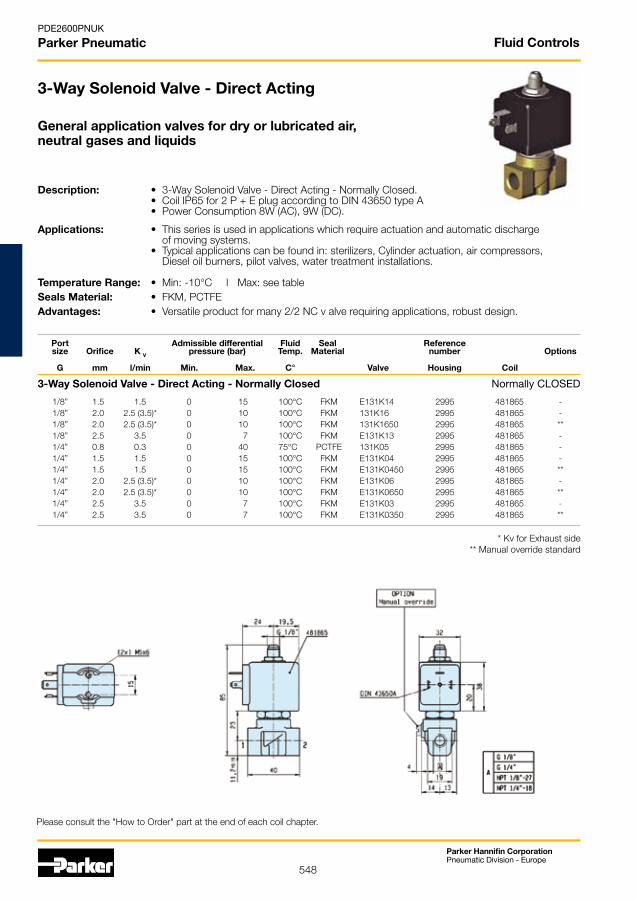
3-Way Solenoid Valve - Direct Acting
Description: • 3-Way Solenoid Valve - Direct Acting - Normally Closed. • Coil IP65 for 2 P + E plug according to DIN 43650 type A • Power Consumption 8W (AC), 9W (DC).
Applications: • This series is used in applications which require actuation and automatic discharge of moving systems. • Typical applications can be found in: sterilizers, Cylinder actuation, air compressors, Diesel oil burners, pilot valves, water treatment installations. Temperature Range: • Min: -10°C l Max: see table Seals Material: • FKM, PCTFEAdvantages: • Versatile product for many 2/2 NC v alve requiring applications, robust design.
* Kv for Exhaust side** Manual override standard
Port Admissible differential Fluid Seal Reference size Orifice K V pressure (bar) Temp. Material number Options G mm l/min Min. Max. C° Valve Housing Coil
3-Way Solenoid Valve - Direct Acting - Normally Closed Normally CLOsED
Fluid Controls
1/8” 1.5 1.5 0 15 100°C FKM E131K14 2995 481865 - 1/8” 2.0 2.5 (3.5)* 0 10 100°C FKM 131K16 2995 481865 - 1/8” 2.0 2.5 (3.5)* 0 10 100°C FKM 131K1650 2995 481865 ** 1/8” 2.5 3.5 0 7 100°C FKM E131K13 2995 481865 - 1/4” 0.8 0.3 0 40 75°C PCTFE 131K05 2995 481865 - 1/4” 1.5 1.5 0 15 100°C FKM E131K04 2995 481865 - 1/4” 1.5 1.5 0 15 100°C FKM E131K0450 2995 481865 ** 1/4” 2.0 2.5 (3.5)* 0 10 100°C FKM E131K06 2995 481865 - 1/4” 2.0 2.5 (3.5)* 0 10 100°C FKM E131K0650 2995 481865 ** 1/4” 2.5 3.5 0 7 100°C FKM E131K03 2995 481865 - 1/4” 2.5 3.5 0 7 100°C FKM E131K0350 2995 481865 **
549
Parker Hannifin CorporationPneumatic Division - Europe
PDE2600PNUK
Parker Pneumatic
D2
D1
"2" "4"
MF
T
D4
D3
Ra 3.2
Valves for Pneumatic Actuator Control
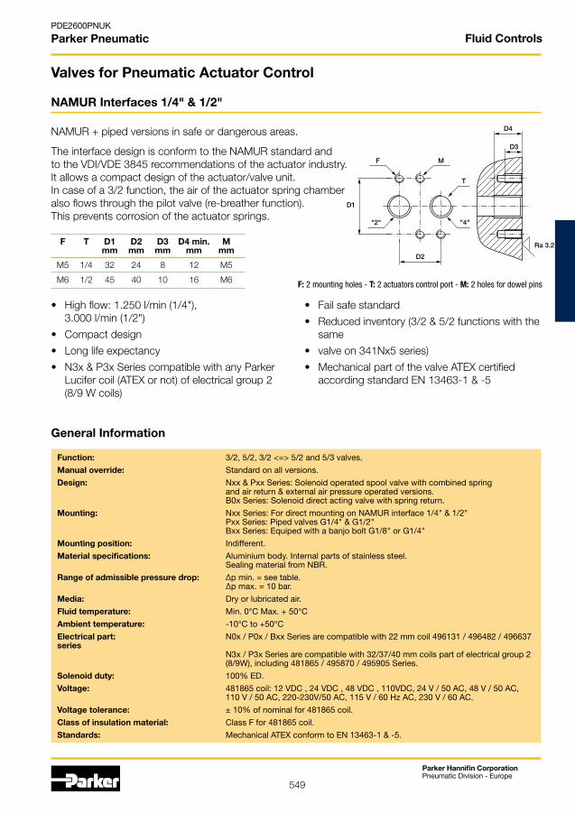
NAMUR Interfaces 1/4" & 1/2"
NAMUR + piped versions in safe or dangerous areas.
The interface design is conform to the NAMUR standard and to the VDI/VDE 3845 recommendations of the actuator industry. It allows a compact design of the actuator/valve unit. In case of a 3/2 function, the air of the actuator spring chamber also flows through the pilot valve (re-breather function).This prevents corrosion of the actuator springs.
F T D1 D2 D3 D4 min. M mm mm mm mm mm
M5 1/4 32 24 8 12 M5
M6 1/2 45 40 10 16 M6 F: 2 mounting holes - T: 2 actuators control port - M: 2 holes for dowel pins
• High flow: 1.250 l/min (1/4"), 3.000 l/min (1/2")
• Compact design
• Long life expectancy
• N3x & P3x Series compatible with any Parker Lucifer coil (ATEX or not) of electrical group 2 (8/9 W coils)
• Fail safe standard
• Reduced inventory (3/2 & 5/2 functions with the same
• valve on 341Nx5 series)
• Mechanical part of the valve ATEX certified according standard EN 13463-1 & -5
Function: 3/2, 5/2, 3/2 <=> 5/2 and 5/3 valves.
Manual override: standard on all versions.
Design: Nxx & Pxx series: solenoid operated spool valve with combined spring and air return & external air pressure operated versions. B0x series: solenoid direct acting valve with spring return.
Mounting: Nxx series: For direct mounting on NAMUR interface 1/4" & 1/2" Pxx series: Piped valves G1/4" & G1/2" Bxx series: Equiped with a banjo bolt G1/8" or G1/4"
Mounting position: Indifferent.
Material specifications: Aluminium body. Internal parts of stainless steel. sealing material from NBR.
Range of admissible pressure drop: ∆p min. = see table. ∆p max. = 10 bar.
Media: Dry or lubricated air.
Fluid temperature: Min. 0°C Max. + 50°C
Ambient temperature: -10°C to +50°C
Electrical part: N0x / P0x / Bxx series are compatible with 22 mm coil 496131 / 496482 / 496637 series N3x / P3x series are compatible with 32/37/40 mm coils part of electrical group 2 (8/9W), including 481865 / 495870 / 495905 series.
Solenoid duty: 100% ED.
Voltage: 481865 coil: 12 VDC , 24 VDC , 48 VDC , 110VDC, 24 V / 50 AC, 48 V / 50 AC, 110 V / 50 AC, 220-230V/50 AC, 115 V / 60 Hz AC, 230 V / 60 AC.
Voltage tolerance: ± 10% of nominal for 481865 coil.
Class of insulation material: Class F for 481865 coil.
Standards: Mechanical ATEX conform to EN 13463-1 & -5.
General Information
Fluid Controls
550
Parker Hannifin CorporationPneumatic Division - Europe
PDE2600PNUK
Parker Pneumatic
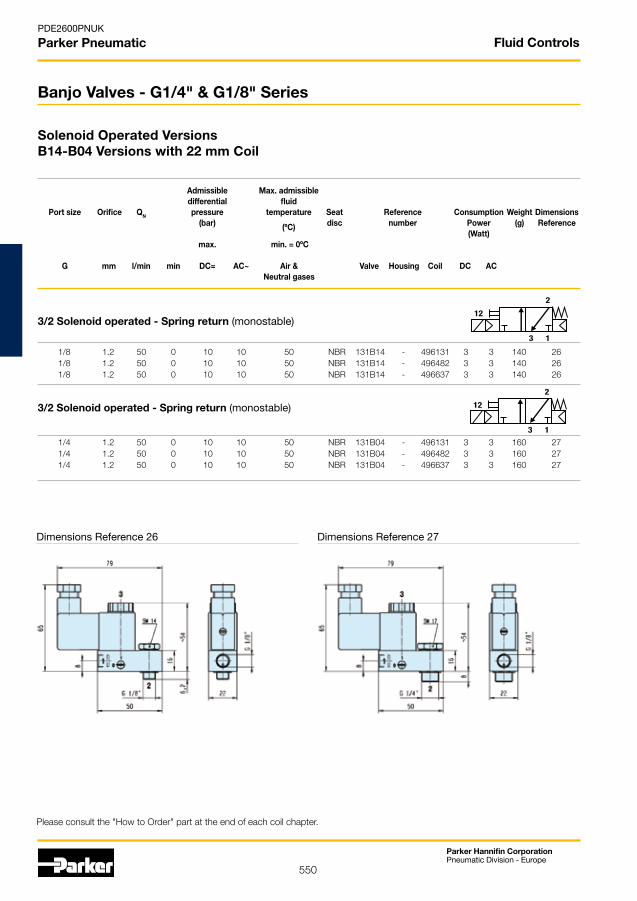
1/8 1.2 50 0 10 10 50 NBR 131B14 - 496131 3 3 140 26 1/8 1.2 50 0 10 10 50 NBR 131B14 - 496482 3 3 140 26 1/8 1.2 50 0 10 10 50 NBR 131B14 - 496637 3 3 140 26
3/2 Solenoid operated - Spring return (monostable)
1/4 1.2 50 0 10 10 50 NBR 131B04 - 496131 3 3 160 27 1/4 1.2 50 0 10 10 50 NBR 131B04 - 496482 3 3 160 27 1/4 1.2 50 0 10 10 50 NBR 131B04 - 496637 3 3 160 27
13
2
12
13
2
12
Please consult the "How to Order" part at the end of each coil chapter.
Solenoid Operated VersionsB14-B04 Versions with 22 mm Coil
Banjo Valves - G1/4" & G1/8" Series
Dimensions Reference 26 Dimensions Reference 27
Admissible Max. admissible differential fluid Port size Orifice QN pressure temperature Seat Reference Consumption Weight Dimensions (bar) (ºC) disc number Power (g) Reference (Watt) max. min. = 0ºC
G mm l/min min DC= AC~ Air & Valve Housing Coil DC AC Neutral gases
3/2 Solenoid operated - Spring return (monostable)
Fluid Controls

551
Parker Hannifin CorporationPneumatic Division - Europe
PDE2600PNUK
Parker Pneumatic
Admissible Max. admissible differential fluid Port size Orifice QN pressure temperature Seat Reference Consumption Weight Dimensions (bar) (ºC) disc number Power (g) Reference (Watt) max. min. = 0ºC
G mm l/min min DC= AC~ Air & Valve Housing Coil DC AC Neutral gases
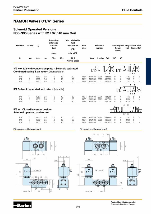
3/2 Solenoid operated - Combined spring & air return (monostable)
1/4 7 1250 2.5 10 10 50 NBR 331N03 - 496131 3 3 300 1 1/4 7 1250 2.5 10 10 50 NBR 331N03 - 496482 3 3 300 1 1/4 7 1250 2.5 10 10 50 NBR 331N03 - 496637 3 3 300 1
5/2 Solenoid operated - Combined spring & air return (monostable)
1/4 7 1250 2.5 10 10 50 NBR 341N03 - 496131 3 3 300 2 1/4 7 1250 2.5 10 10 50 NBR 341N03 - 496482 3 3 300 2 1/4 7 1250 2.5 10 10 50 NBR 341N03 - 496637 3 3 300 2
3/2 <=> 5/2 with conversion plate - Solenoid operatedCombined spring & air return (monostable)
1/4 7 1250 2.5 10 10 50 NBR 341N05 - 496131 3 3 310 3 1/4 7 1250 2.5 10 10 50 NBR 341N05 - 496482 3 3 310 3 1/4 7 1250 2.5 10 10 50 NBR 341N05 - 496637 3 3 310 3
5/2 Solenoid operated and return (bistable)
1/4 7 1250 2.5 10 10 50 NBR 347N03 - 496131 3 3 430 4 1/4 7 1250 2.5 10 10 50 NBR 347N03 - 496482 3 3 430 4 1/4 7 1250 2.5 10 10 50 NBR 347N03 - 496637 3 3 430 4
5/3 W1 closed in center position - Solenoid operated and return
1/4 7 1250 2.5 10 10 50 NBR 342N03 - 496131 3 3 430 4 1/4 7 1250 2.5 10 10 50 NBR 342N03 - 496482 3 3 430 4 1/4 7 1250 2.5 10 10 50 NBR 342N03 - 496637 3 3 430 4
5/3 W3 exhausted in center positionSolenoid operated and return
1/4 7 1250 2.5 10 10 50 NBR 343N03 - 496131 3 3 430 4 1/4 7 1250 2.5 10 10 50 NBR 343N03 - 496482 3 3 430 4 1/4 7 1250 2.5 10 10 50 NBR 343N03 - 496637 3 3 430
13
2
13
2
1 35
24
1 35
24
1 35
24
1 35
24
1 35
24
NAMUR Valves G1/4" Series
Solenoid Operated Versions N03-N05 Series with 22 mm Coil
Please consult the "How to Order" part at the end of each coil chapter.
Fluid Controls

552
Parker Hannifin CorporationPneumatic Division - Europe
PDE2600PNUK
Parker Pneumatic
40 40
404032
323222
22 22
22
32 32
67
67 676767
50 50
50 50 50
13 13
13 13
13 13
13 13
44 44
44 22 22
36.5 36.5
G1/4" (2x) G1/4" (3x)
G1/4" (3x)
G1/4" (3x)
M5 M5
M5
M5
23 23
2323
36,5
24 24
2424
23 23
2323
86 86
102 90
12 14
14
10 12
12
3 4
4
3 5
55
1 3
33
2 2
2
7.2 7.2
7.2
7.2
Dimensions Reference 1 Dimensions Reference 2
Please consult the "How to Order" part at the end of each coil chapter.
Fluid Controls
Dimensions Reference 3 Dimensions Reference 4
553
Parker Hannifin CorporationPneumatic Division - Europe
PDE2600PNUK
Parker Pneumatic
19.5 24
G1/8"
4032
100
23 2324
13 13 22 22
4032
130
23 2324
14 12
24
87
38
32
DIN 43650A
5 3
G1/4" (3x) M5
22
7.2
97
38
13
19.5
13 22
24
32
DIN 43650A
G1/8"
22
5 3
G1/4" (3x) M5
22
32
7.5
13
2
1 35
24
1 35
24
1 35
24
NAMUR Valves G1/4" Series
Solenoid Operated Versions N33-N35 Series with 32 / 37 / 40 mm Coil
Dimensions Reference 5 Dimensions Reference 6
Admissible Max. admissible differential fluid Port size Orifice QN pressure temperature Seat Reference Consumption Weight Elect. Dim. (bar) (ºC) disc number Power (g) Group Ref. (Watt) max. min. = 0ºC
G mm l/min min DC= AC~ Air & Valve Housing Coil DC AC Neutral gases
Fluid Controls
3/2 <=> 5/2 with conversion plate - Solenoid operated Combined spring & air return (monostable)
1/4 7 1250 2.5 10 10 50 NBR 341N35 2995 481865 9 8 480 2 5 1/4 7 1250 2.5 10 10 50 NBR 341N35 2995 495870 9 8 700 2 - 1/4 7 1250 2.5 10 10 50 NBR 341N35 - 495905 8 8 740 2 -
5/2 Solenoid operated and return (bistable)
1/4 7 1250 2.5 10 10 50 NBR 347N33 2995 481865 9 8 750 2 6 1/4 7 1250 2.5 10 10 50 NBR 347N33 2995 495870 9 8 1190 2 - 1/4 7 1250 2.5 10 10 50 NBR 347N33 - 495905 8 8 1270 2 -
5/3 W1 Closed in center positionSolenoid operated and return
1/4 7 1250 2.5 10 10 50 NBR 342N33 2995 481865 9 8 750 2 6 1/4 7 1250 2.5 10 10 50 NBR 342N33 2995 495870 9 8 1190 2 - 1/4 7 1250 2.5 10 10 50 NBR 342N33 - 495905 8 8 1270 2 -
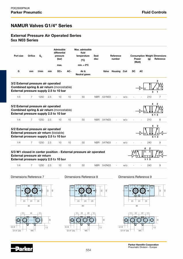
554
Parker Hannifin CorporationPneumatic Division - Europe
PDE2600PNUK
Parker Pneumatic
Admissible Max. admissible differential fluid Port size Orifice QN pressure temperature Seat Reference Consumption Weight Dimensions (bar) (ºC) disc number Power (g) Reference (Watt) max. min. = 0ºC
G mm l/min min DC= AC~ Air & Valve Housing Coil DC AC Neutral gases
3/2 External pressure air operatedCombined spring & air return (monostable)External pressure supply 2.5 to 10 bar
1/4 7 1250 2.5 10 10 50 NBR 531N03 - w/o - - 210 7
5/2 External pressure air operatedCombined spring & air return (monostable)External pressure supply 2.5 to 10 bar
1/4 7 1250 2.5 10 10 50 NBR 541N03 - w/o - - 210 8
5/2 External pressure air operatedExternal pressure air return (bistable)External pressure supply 2.5 to 10 bar
1/4 7 1250 2.5 10 10 50 NBR 547N03 - w/o - - 240 9
5/3 W1 closed in center position - External pressure air operatedExternal pressure air returnExternal pressure supply 2.5 to 10 bar
1/4 7 1250 2.5 10 10 50 NBR 542N03 - w/o - - 240 9
40 40 4032 32 32
13 13 13 13 13 13 44 22 22 22 22
86 86 86
23 23 2323 23 2324 24 24
3 5 51 3 3
G1/4" (2x) G1/4" (3x) G1/4" (3x)
G1/8 G1/8 G1/8
M5 M5 M5
22 22 22
7.2 7.2 7.2
13
2
1 35
24
1 35
24
1 35
24
External Pressure Air Operated Series5xx N03 Series
NAMUR Valves G1/4" Series
Dimensions Reference 7 Dimensions Reference 8 Dimensions Reference 9
Fluid Controls

555
Parker Hannifin CorporationPneumatic Division - Europe
PDE2600PNUK
Parker Pneumatic
3/2 Solenoid operated Combined spring & air return (monostable)
1/2 12 3000 2.5 10 10 50 NBR 331N04 - 496131 3 3 910 670 10 1/2 12 3000 2.5 10 10 50 NBR 331N04 - 496482 3 3 1130 670 10 1/2 12 3000 2.5 10 10 50 NBR 331N04 - 496637 3 3 1170 670 10
5/2 Solenoid operatedCombined spring & air return (monostable)
1/2 12 3000 2.5 10 10 50 NBR 341N04 - 496131 3 3 900 840 11 1/2 12 3000 2.5 10 10 50 NBR 341N04 - 496482 3 3 1120 840 11 1/2 12 3000 2.5 10 10 50 NBR 341N04 - 496637 3 3 1160 840 11
5/2 Solenoid operated and return (bistable)
1/2 12 3000 2.5 10 10 50 NBR 347N04 - 496131 3 3 1240 840 12 1/2 12 3000 2.5 10 10 50 NBR 347N04 - 496482 3 3 1680 840 12 1/2 12 3000 2.5 10 10 50 NBR 347N04 - 496637 3 3 1760 840 12
1 35
24
14
1 35
24
14
1 35
14 17
Please consult the "How to Order" part at the end of each coil chapter.
Solenoid Operated VersionsN04 Versions with 22 mm Coil
NAMUR Valves G1/2" Series
Dimensions Reference 10 Dimensions Reference 11 Dimensions Reference 12
Admissible Max. admissible differential fluid Port size Orifice QN pressure temperature Seat Reference Consumption Weight Dimensions (bar) (ºC) disc number Power (g) Reference (Watt) max. min. = 0ºC
G mm l/min min DC= AC~ Air & Valve Housing Coil DC AC Neutral gases
Fluid Controls

556
Parker Hannifin CorporationPneumatic Division - Europe
PDE2600PNUK
Parker Pneumatic
3/2 Solenoid operated Combined spring & air return (monostable)
1/2 12 3000 2.5 10 10 50 NBR 331N34 2995 481865 9 8 910 2 13 1/2 12 3000 2.5 10 10 50 NBR 331N34 2995 495870 9 8 1130 2 - 1/2 12 3000 2.5 10 10 50 NBR 331N34 - 495905 8 8 1170 2 -
5/2 Solenoid operatedCombined spring & air return (monostable)
1/2 12 3000 2.5 10 10 50 NBR 341N34 2995 481865 9 8 900 2 14 1/2 12 3000 2.5 10 10 50 NBR 341N34 2995 495870 9 8 1120 2 - 1/2 12 3000 2.5 10 10 50 NBR 341N34 - 495905 8 8 1160 2 -
5/2 Solenoid operated and return (bistable)
1/2 12 3000 2.5 10 10 50 NBR 347N34 2995 481865 9 8 1240 2 15 1/2 12 3000 2.5 10 10 50 NBR 347N34 2995 495870 9 8 1680 2 - 1/2 12 3000 2.5 10 10 50 NBR 347N34 - 495905 8 8 1760 2 -
13
2
1 35
24
1 35
24
Solenoid Operated VersionsN34 Series with 32 / 37 / 40 mm Coil
NAMUR Valves G1/2" Series
Please consult the "How to Order" part at the end of each coil chapter.
Dimensions Reference 13 Dimensions Reference 14 Dimensions Reference 15
Admissible Max. admissible differential fluid Port size Orifice QN pressure temperature Seat Reference Consumption Weight Elect. Dim. (bar) (ºC) disc number Power (g) Group Ref. (Watt) max. min. = 0ºC
G mm l/min min DC= AC~ Air & Valve Housing Coil DC AC Neutral gases
Fluid Controls
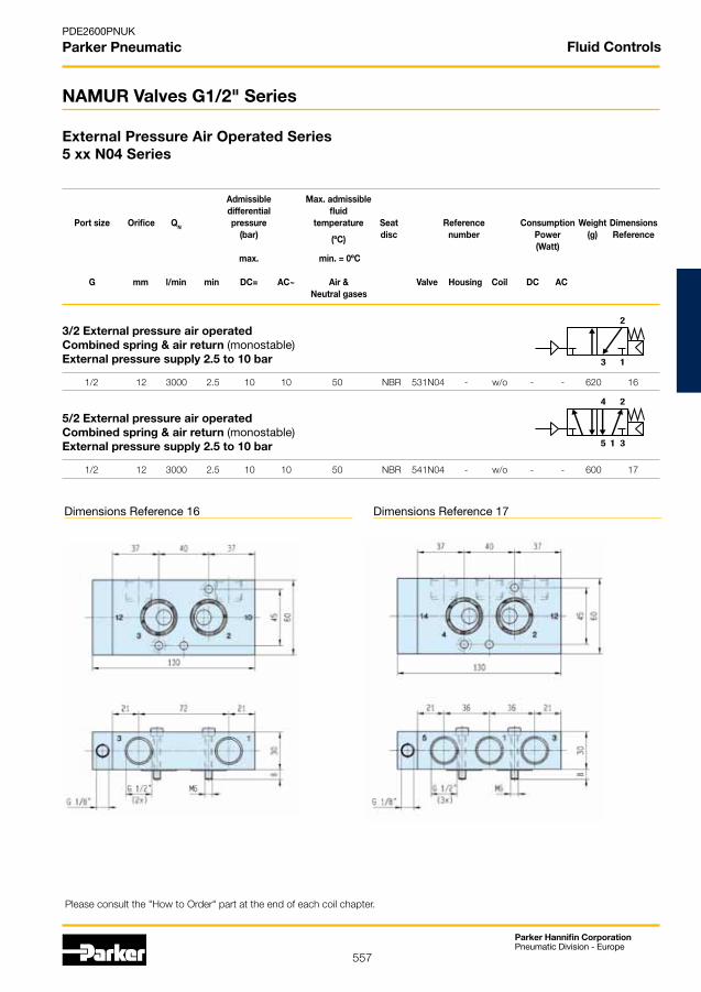
557
Parker Hannifin CorporationPneumatic Division - Europe
PDE2600PNUK
Parker Pneumatic
13
2
1 35
24
External Pressure Air Operated Series5 xx N04 Series
NAMUR Valves G1/2" Series
Dimensions Reference 16 Dimensions Reference 17
Admissible Max. admissible differential fluid Port size Orifice QN pressure temperature Seat Reference Consumption Weight Dimensions (bar) (ºC) disc number Power (g) Reference (Watt) max. min. = 0ºC
G mm l/min min DC= AC~ Air & Valve Housing Coil DC AC Neutral gases
Please consult the "How to Order" part at the end of each coil chapter.
Fluid Controls
3/2 External pressure air operatedCombined spring & air return (monostable)External pressure supply 2.5 to 10 bar
1/2 12 3000 2.5 10 10 50 NBR 531N04 - w/o - - 620 16
5/2 External pressure air operatedCombined spring & air return (monostable)External pressure supply 2.5 to 10 bar
1/2 12 3000 2.5 10 10 50 NBR 541N04 - w/o - - 600 17

558
Parker Hannifin CorporationPneumatic Division - Europe
PDE2600PNUK
Parker Pneumatic
5/2 Solenoid operated Combined spring & air return (monostable)
1/4 7 1250 2.5 10 10 50 NBR 341P03 - 496131 3 3 250 18 1/4 7 1250 2.5 10 10 50 NBR 341P03 - 496482 3 3 250 18 1/4 7 1250 2.5 10 10 50 NBR 341P03 - 496637 3 3 250 18
5/2 Solenoid operated and return (bistable)
1/4 7 1250 2.5 10 10 50 NBR 347P03 - 496131 3 3 350 19 1/4 7 1250 2.5 10 10 50 NBR 347P03 - 496482 3 3 350 19 1/4 7 1250 2.5 10 10 50 NBR 347P03 - 496637 3 3 350 19
1 35
24
14
1 35
14 17
Please consult the "How to Order" part at the end of each coil chapter.
Piped Valves - G1/4" Series
Solenoid Operated VersionsP03 Versions with 22 mm Coil
Admissible Max. admissible differential fluid Port size Orifice QN pressure temperature Seat Reference Consumption Weight Dimensions (bar) (ºC) disc number Power (g) Reference (Watt) max. min. = 0ºC
G mm l/min min DC= AC~ Air & Valve Housing Coil DC AC Neutral gases
Fluid Controls
Dimensions Reference 18 Dimensions Reference 19

559
Parker Hannifin CorporationPneumatic Division - Europe
PDE2600PNUK
Parker Pneumatic
1 35
24
14
1 35
14 17
Piped Valves - G1/4" Series
Solenoid Operated VersionsP33 Versions with 32-37-40 mm Coil
Dimensions Reference 20 Dimensions Reference 21
Admissible Max. admissible differential fluid Port size Orifice QN pressure temperature Seat Reference Consumption Weight Elect. Dim. (bar) (ºC) disc number Power (g) Group Ref. (Watt) max. min. = 0ºC
G mm l/min min DC= AC~ Air & Valve Housing Coil DC AC Neutral gases
Fluid Controls
5/2 Solenoid operated Combined spring & air return (monostable)
1/4 7 1250 2.5 10 10 50 NBR 341P33 2995 481865 9 8 470 2 20 1/4 7 1250 2.5 10 10 50 NBR 341P33 2995 495870 9 8 690 2 - 1/4 7 1250 2.5 10 10 50 NBR 341P33 - 495905 8 8 730 2 -
5//2 Solenoid operated and return (bistable)
1/4 7 1250 2.5 10 10 50 NBR 347P33 2995 481865 9 8 750 2 21 1/4 7 1250 2.5 10 10 50 NBR 347P33 2995 495870 9 8 1190 2 - 1/4 7 1250 2.5 10 10 50 NBR 347P33 - 495905 8 8 1270 2 -
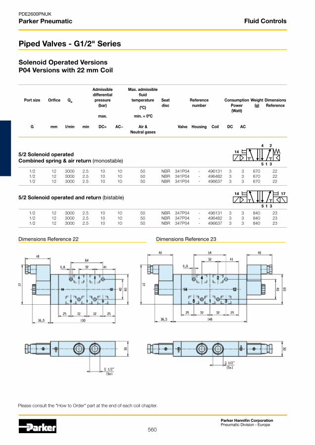
560
Parker Hannifin CorporationPneumatic Division - Europe
PDE2600PNUK
Parker Pneumatic
1 35
14 17
1 35
24
14
Please consult the "How to Order" part at the end of each coil chapter.
Solenoid Operated VersionsP04 Versions with 22 mm Coil
Piped Valves - G1/2" Series
Admissible Max. admissible differential fluid Port size Orifice QN pressure temperature Seat Reference Consumption Weight Dimensions (bar) (ºC) disc number Power (g) Reference (Watt) max. min. = 0ºC
G mm l/min min DC= AC~ Air & Valve Housing Coil DC AC Neutral gases
Fluid Controls
Dimensions Reference 22 Dimensions Reference 23
5/2 Solenoid operated Combined spring & air return (monostable)
1/2 12 3000 2.5 10 10 50 NBR 341P04 - 496131 3 3 670 22 1/2 12 3000 2.5 10 10 50 NBR 341P04 - 496482 3 3 670 22 1/2 12 3000 2.5 10 10 50 NBR 341P04 - 496637 3 3 670 22
5/2 Solenoid operated and return (bistable)
1/2 12 3000 2.5 10 10 50 NBR 347P04 - 496131 3 3 840 23 1/2 12 3000 2.5 10 10 50 NBR 347P04 - 496482 3 3 840 23 1/2 12 3000 2.5 10 10 50 NBR 347P04 - 496637 3 3 840 23

561
Parker Hannifin CorporationPneumatic Division - Europe
PDE2600PNUK
Parker Pneumatic
5/2 Solenoid operated Combined spring & air return (monostable)
1/2 12 3000 2.5 10 10 50 NBR 341P34 2995 481865 9 8 900 2 24 1/2 12 3000 2.5 10 10 50 NBR 341P34 2995 495870 9 8 1120 2 - 1/2 12 3000 2.5 10 10 50 NBR 341P34 - 495905 8 8 1160 2 -
5/2 Solenoid operated and return (bistable)
1/2 12 3000 2.5 10 10 50 NBR 347P34 2995 481865 9 8 1240 2 25 1/2 12 3000 2.5 10 10 50 NBR 347P34 2995 495870 9 8 1680 2 - 1/2 12 3000 2.5 10 10 50 NBR 347P34 - 495905 8 8 1760 2 -
1 35
24
14
1 35
14 17
Please consult the "How to Order" part at the end of each coil chapter.
Solenoid Operated VersionsP34 Versions with 32/37/40 mm Coil
Piped Valves - G1/2" Series
Dimensions Reference 24 Dimensions Reference 25
Admissible Max. admissible differential fluid Port size Orifice QN pressure temperature Seat Reference Consumption Weight Elect. Dim. (bar) (ºC) disc number Power (g) Group Ref. (Watt) max. min. = 0ºC
G mm l/min min DC= AC~ Air & Valve Housing Coil DC AC Neutral gases
Fluid Controls

562
Parker Hannifin CorporationPneumatic Division - Europe
PDE2600PNUK
Parker Pneumatic
• Power: 3W
• Insulation Class: F (155°C)
• Degree of Protection: IP65 (with plug)
• Duty Cycle: 100% ED
• Ambient Temperature: -10°C to 50°C
3 different types are available:
• Ref. 496131 for a safe area without plug
• Ref. 496482 for a safe area with plug
• Ref. 496637 for an ATEX area Zone 22
Coils and Spare Parts Informations
496637 coil series with connection 2P + G when mounted together with the supplied Pg9 plug (delivered with the coil) are suitable for use in dangerous areas (dust Zone 22) according to the European directive ATEX 94/9/C. Protection mode: Ex tD A22 IP65 - T95°C
Available Safe area Safe area ATEX Voltages without DIN plug with DIN plug Zone 22 EX II 3D Order Order Order Code Code Code
12 VDC 496131 C1 496482 C1 496637 C1
24 VDC 496131 C2 496482 C2 496637 C2
48 VDC 496131 C4 496482 C4 496637 C4
110 VDC 496131 C5 496482 C5 496637 C5
24/50-60 VAC 496131 P0 496482 P0 496637 P0
48/50-60 VAC 496131 S4 496482 S4 496637 S4
110/50-60 VAC 496131 P2 496482 P2 496637 P2
115/60 VAC 496131 K8 496482 K8 496637 K8
230/50-60 VAC 496131 P9 496482 P9 496637 P9
How to Order
The housing kit is already included into the coil reference, so it’s not needed to add it with the order code:
Valve Reference Number - Coil Reference - Voltage code = Order code
Example: 341N03 - 496131 C2Valves and coils may be ordered also separately.
Coils 22 mm for N03-N05 Series
Safe Area & ATEX Zone 22 Ref. 496131 / 496482 / 496637
These coils with connection for 2 P+G DIN 43650 B plug are encapsulated in synthetic material, conform to the IEC/CENELEC safety standards and comply with European low voltage directive 73/23/EC .
Fluid Controls
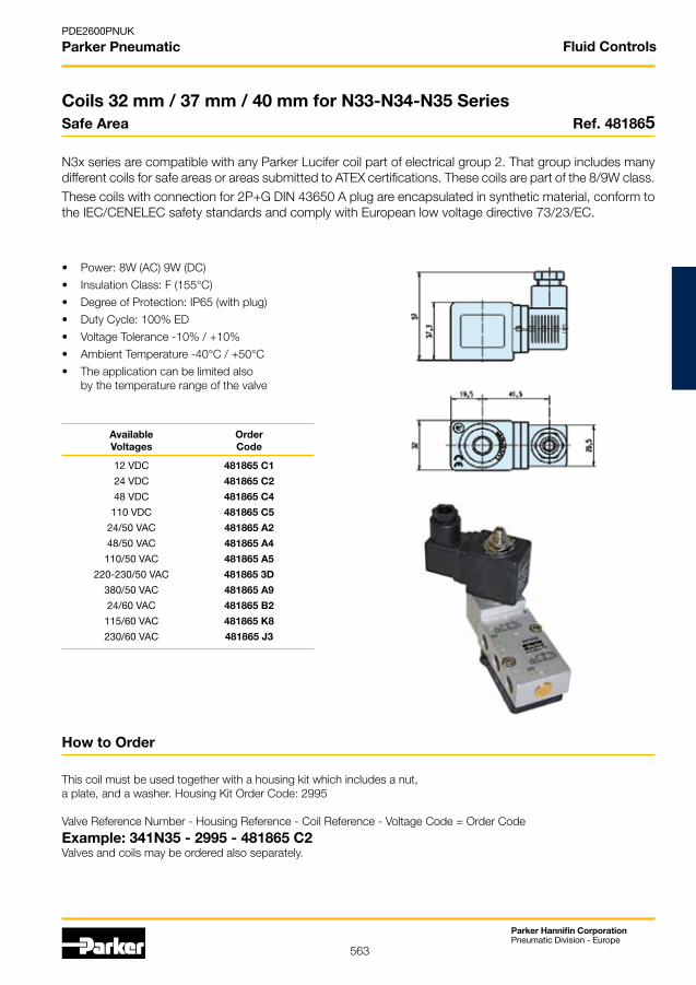
563
Parker Hannifin CorporationPneumatic Division - Europe
PDE2600PNUK
Parker Pneumatic
• Power: 8W (AC) 9W (DC)
• Insulation Class: F (155°C)
• Degree of Protection: IP65 (with plug)
• Duty Cycle: 100% ED
• Voltage Tolerance -10% / +10%
• Ambient Temperature -40°C / +50°C
• The application can be limited also by the temperature range of the valve
Available Order Voltages Code
12 VDC 481865 C1
24 VDC 481865 C2
48 VDC 481865 C4
110 VDC 481865 C5
24/50 VAC 481865 A2
48/50 VAC 481865 A4
110/50 VAC 481865 A5
220-230/50 VAC 481865 3D
380/50 VAC 481865 A9
24/60 VAC 481865 B2
115/60 VAC 481865 K8
230/60 VAC 481865 J3
How to Order
This coil must be used together with a housing kit which includes a nut, a plate, and a washer. Housing Kit Order Code: 2995
Valve Reference Number - Housing Reference - Coil Reference - Voltage Code = Order Code
Example: 341N35 - 2995 - 481865 C2Valves and coils may be ordered also separately.
Coils 32 mm / 37 mm / 40 mm for N33-N34-N35 SeriesSafe Area Ref. 481865
N3x series are compatible with any Parker Lucifer coil part of electrical group 2. That group includes many different coils for safe areas or areas submitted to ATEX certifications. These coils are part of the 8/9W class. These coils with connection for 2P+G DIN 43650 A plug are encapsulated in synthetic material, conform to the IEC/CENELEC safety standards and comply with European low voltage directive 73/23/EC.
Fluid Controls
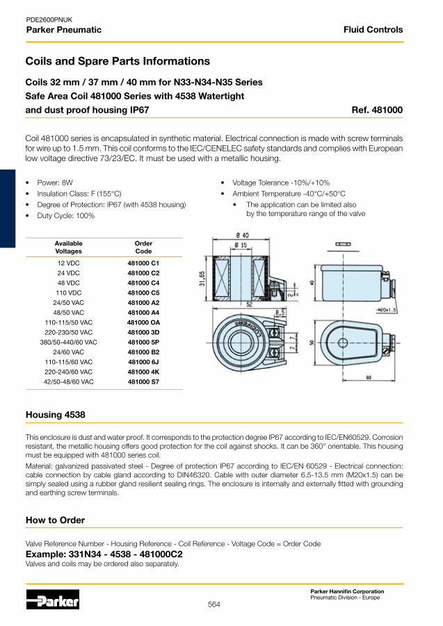
564
Parker Hannifin CorporationPneumatic Division - Europe
PDE2600PNUK
Parker Pneumatic
Coils and Spare Parts Informations
• Power: 8W
• Insulation Class: F (155°C)
• Degree of Protection: IP67 (with 4538 housing)
• Duty Cycle: 100%
• Voltage Tolerance -10%/+10%
• Ambient Temperature -40°C/+50°C
• The application can be limited also by the temperature range of the valve
How to Order
Valve Reference Number - Housing Reference - Coil Reference - Voltage Code = Order Code
Example: 331N34 - 4538 - 481000C2Valves and coils may be ordered also separately.
Housing 4538
This enclosure is dust and water proof. It corresponds to the protection degree IP67 according to IEC/EN60529. Corrosion resistant, the metallic housing offers good protection for the coil against shocks. It can be 360° orientable. This housing must be equipped with 481000 series coil.
Material: galvanized passivated steel - Degree of protection IP67 according to IEC/EN 60529 - Electrical connection: cable connection by cable gland according to DIN46320. Cable with outer diameter 6.5-13.5 mm (M20x1.5) can be simply sealed using a rubber gland resilient sealing rings. The enclosure is internally and externally fitted with grounding and earthing screw terminals.
Coils 32 mm / 37 mm / 40 mm for N33-N34-N35 Series
Safe Area Coil 481000 Series with 4538 Watertight
and dust proof housing IP67 Ref. 481000
Coil 481000 series is encapsulated in synthetic material. Electrical connection is made with screw terminals for wire up to 1.5 mm. This coil conforms to the IEC/CENELEC safety standards and complies with European low voltage directive 73/23/EC. It must be used with a metallic housing.
Available Order Voltages Code
12 VDC 481000 C1
24 VDC 481000 C2
48 VDC 481000 C4
110 VDC 481000 C5
24/50 VAC 481000 A2
48/50 VAC 481000 A4
110-115/50 VAC 481000 OA
220-230/50 VAC 481000 3D
380/50-440/60 VAC 481000 5P
24/60 VAC 481000 B2
110-115/60 VAC 481000 6J
220-240/60 VAC 481000 4K
42/50-48/60 VAC 481000 S7
Fluid Controls
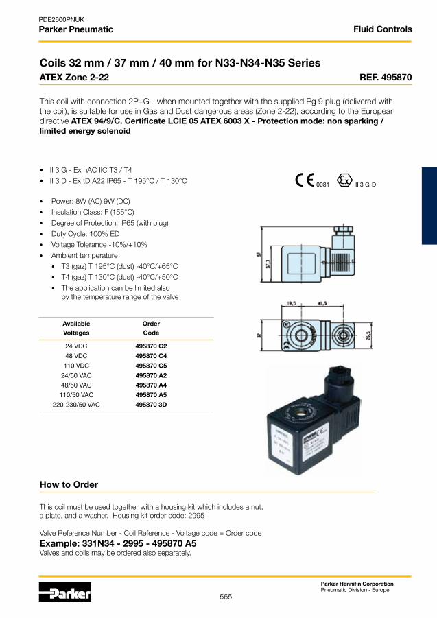
565
Parker Hannifin CorporationPneumatic Division - Europe
PDE2600PNUK
Parker Pneumatic
0081 II 3 G-D
• II 3 G - Ex nAC IIC T3 / T4
• II 3 D - Ex tD A22 IP65 - T 195°C / T 130°C
• Power: 8W (AC) 9W (DC)
• Insulation Class: F (155°C)
• Degree of Protection: IP65 (with plug)
• Duty Cycle: 100% ED
• Voltage Tolerance -10%/+10%
• Ambient temperature
• T3 (gaz) T 195°C (dust) -40°C/+65°C
• T4 (gaz) T 130°C (dust) -40°C/+50°C
• The application can be limited also by the temperature range of the valve
Available Order Voltages Code
24 VDC 495870 C2
48 VDC 495870 C4
110 VDC 495870 C5
24/50 VAC 495870 A2
48/50 VAC 495870 A4
110/50 VAC 495870 A5
220-230/50 VAC 495870 3D
How to Order
This coil must be used together with a housing kit which includes a nut, a plate, and a washer. Housing kit order code: 2995
Valve Reference Number - Coil Reference - Voltage code = Order code
Example: 331N34 - 2995 - 495870 A5Valves and coils may be ordered also separately.
Coils 32 mm / 37 mm / 40 mm for N33-N34-N35 SeriesATEX Zone 2-22 REF. 495870
This coil with connection 2P+G - when mounted together with the supplied Pg 9 plug (delivered with the coil), is suitable for use in Gas and Dust dangerous areas (Zone 2-22), according to the European directive ATEX 94/9/C. Certificate LCIE 05 ATEX 6003 X - Protection mode: non sparking / limited energy solenoid
Fluid Controls
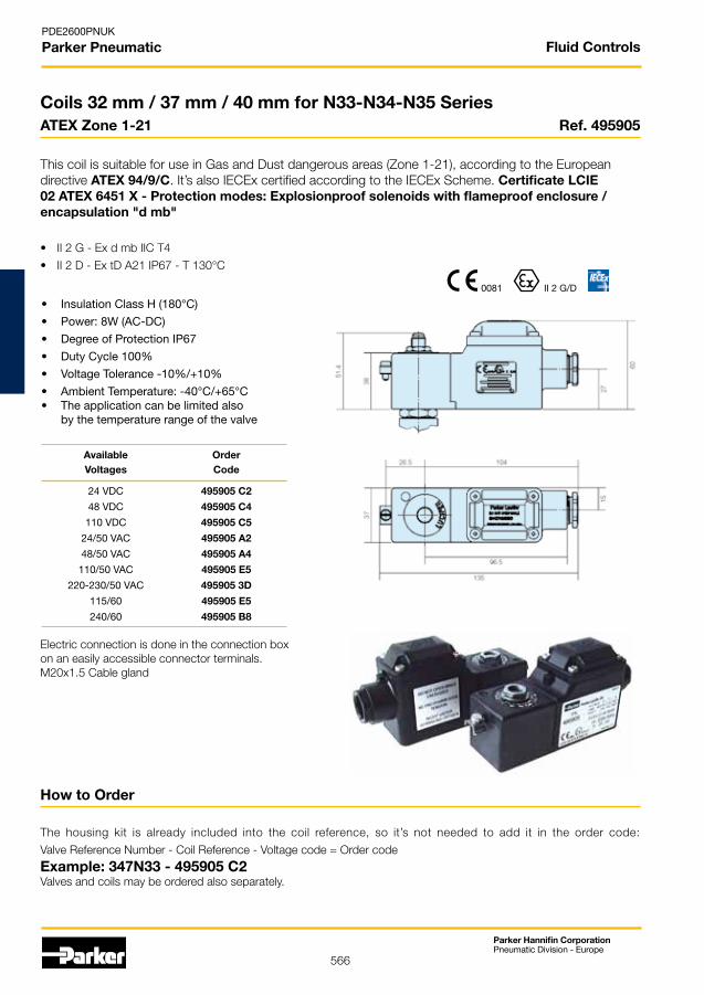
566
Parker Hannifin CorporationPneumatic Division - Europe
PDE2600PNUK
Parker Pneumatic
0081 II 2 G/D
• II 2 G - Ex d mb IIC T4
• II 2 D - Ex tD A21 IP67 - T 130°C
• Insulation Class H (180°C)
• Power: 8W (AC-DC)
• Degree of Protection IP67
• Duty Cycle 100%
• Voltage Tolerance -10%/+10%
• Ambient Temperature: -40°C/+65°C• The application can be limited also by the temperature range of the valve
Available Order Voltages Code
24 VDC 495905 C2
48 VDC 495905 C4
110 VDC 495905 C5
24/50 VAC 495905 A2
48/50 VAC 495905 A4
110/50 VAC 495905 E5
220-230/50 VAC 495905 3D
115/60 495905 E5
240/60 495905 B8
Electric connection is done in the connection boxon an easily accessible connector terminals.M20x1.5 Cable gland
How to Order
The housing kit is already included into the coil reference, so it’s not needed to add it in the order code:
Valve Reference Number - Coil Reference - Voltage code = Order code
Example: 347N33 - 495905 C2Valves and coils may be ordered also separately.
Coils 32 mm / 37 mm / 40 mm for N33-N34-N35 SeriesATEX Zone 1-21 Ref. 495905
This coil is suitable for use in Gas and Dust dangerous areas (Zone 1-21), according to the European directive ATEX 94/9/C. It’s also IECEx certified according to the IECEx Scheme. Certificate LCIE 02 ATEX 6451 X - Protection modes: Explosionproof solenoids with flameproof enclosure / encapsulation "d mb"
Fluid Controls
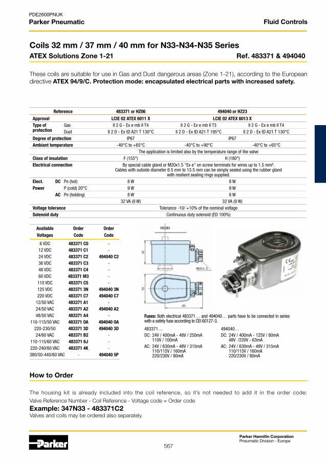
567
Parker Hannifin CorporationPneumatic Division - Europe
PDE2600PNUK
Parker Pneumatic
How to Order
The housing kit is already included into the coil reference, so it’s not needed to add it in the order code:
Valve Reference Number - Coil Reference - Voltage code = Order code
Example: 347N33 - 483371C2Valves and coils may be ordered also separately.
Coils 32 mm / 37 mm / 40 mm for N33-N34-N35 SeriesATEX Solutions Zone 1-21 Ref. 483371 & 494040
These coils are suitable for use in Gas and Dust dangerous areas (Zone 1-21), according to the European directive ATEX 94/9/C. Protection mode: encapsulated electrical parts with increased safety.
483371…DC: 24V / 400mA - 48V / 250mA 110V / 100mAAC: 24V / 630mA - 48V / 315mA 110/115V / 160mA 220/230V / 80mA
494040…DC: 24V / 400mA - 125V / 80mA 48V /220V - 63mAAC: 24V / 630mA - 48V / 315mA 110/115V / 160mA 220/230V / 80mA
Fuses: Both electrical 483371… and 494040… parts have to be connected in series with a safety fuse according to CEI 60127-3.
Available Order Order Voltages Code Code
6 VDC 483371 C0 - 12 VDC 483371 C1 - 24 VDC 483371 C2 494040 C2 36 VDC 483371 C3 - 48 VDC 483371 C4 - 60 VDC 483371 M3 - 110 VDC 483371 C5 - 125 VDC 483371 3N 494040 3N 220 VDC 483371 C7 494040 C7 12/50 VAC 483371 A1 - 24/50 VAC 483371 A2 494040 A2 48/50 VAC 483371 A4 - 110-115/50 VAC 483371 OA 494040 OA 220-230/50 483371 3D 494040 3D 24/60 VAC 483371 B2 - 110-115/60 VAC 483371 6J - 220-240/60 VAC 483371 4K - 380/50-440/60 VAC - 494040 5P
Reference 483371 or HZ06 494040 or HZ23
Approval LCIE 02 ATEX 6011 X LCIE 02 ATEX 6013 X Type of Gas II 2 G - Ex e mb II T4 II 2 G - Ex e mb II T3 II 2 G - Ex e mb II T4 protection Dust II 2 D - Ex tD A21 T 130°C II 2 D - Ex tD A21 T 195°C II 2 D - Ex tD A21 T 130°C Degree of protection IP67 IP67 Ambiant temperature -40°C to +65°C -40°C to +90°C -40°C to +65°C The application is limited also by the temperature range of the valve Class of insulation F (155°) H (180°) Electrical connection By special cable gland or M20x1.5 "Ex e" on screw terminals for wires up to 1.5 mm². Cables with outside diameter 6.5 mm to 13.5 mm can be simply sealed using the rubber gland with resilient sealing rings supplied. Elect. DC Pn (hot) 8 W 8 W Power P (cold) 20°C 9 W 9 W AC Pn (holding) 8 W 8 W 32 VA (9 W) 32 VA (9 W) Voltage tolerance Tolerance -10/ +10% of the nominal voltage Solenoid duty Continuous duty solenoid (ED 100%)
Fluid Controls

568
Parker Hannifin CorporationPneumatic Division - Europe
PDE2600PNUK
Parker Pneumatic
Spare Parts Mounting Kit and Accessories
Exhaust Flow Regulators
Material Body: Brass Filter element: Sintered bronzeSpring: Stainless Steel Seal: NBR
G1/8" Order code: 496551 G1/4" Order code: 496552 G1/2" Order code: 496553
Kit for G1/4" Models
without conversion plate (N x 3 Series)
Kit includes the 2 mounting screws M5 x 25 A2, the dowel pin M5 x 10 A2, the 2 O-rings NBR 15 x 2.5Order code: 496132
Kit for G1/2" Models (N x 4 Series)
Kit includes the 2 mounting screws M6 x 35 A2, the dowel pin M6 x 12 A2, the 2 O-rings NBR 24 x 3Order code: 496133
Kit for G1/4" Models
with conversion plate (N x 5 Series)
Kit includes the 2 mounting screws M5 x 35 A2, the dowel pin M5 x 20 A2, the conversion plate equipped with its sealsOrder code: 496742 (equipped plate)Order code: 496852 (screws + pin)
Fluid Controls

569
Parker Hannifin CorporationPneumatic Division - Europe
PDE2600PNUK
Parker Pneumatic
Connector for 32 mm Coil
Connector DIN43650 AA Pg9 2P+EOrder code: 486586
Housing for 22 mm Coil
Plastic nut with O-ringOrder code: 3125
Connector for 22 mm Coil
Connector DIN43650 AB Pg9 2P+EOrder code: 481043
Fluid Controls

570
Parker Hannifin CorporationPneumatic Division - Europe
PDE2600PNUK
Parker Pneumatic
Ex Bus Manifold
for pneumatic actuator control
Parkers EExPressTM bus manifold package has been designed for the control of pneumatic actuators in the Process Industry where hazardous environments Zone 1, 21 and or Zone 2, 22 are present.
EExPressTM is a stackable system that includes Gateway - Input sensor modules - Solenoid valve modules.
NAMUR Standard ON/OFF Where the (NPN) sensor can be directly connected on the input sensor module.
The Ex manifold uses the Profibus DP protocol.
Increased Process Productivity
• When plant installation’s are simplified, the engineering study, component package’s and man hour costs are reduced, this results in a quicker production start-up.
• Through more efficient process control, quality and quantity of production is improved.
• EExPressTM bus manifold replaces a lot of proprietary components, thus reducing cost of installation.
• EExPressTM bus manifold simplifies commissioning time resulting in quicker plant start up time.
• EExPressTM bus manifold reduces overall product life cost through reduction in maintenance costs.
A User Friendly Product
• EExPressTM uses the well known profibus DP protocol.
• It as been designed to aproach a "plug and play" usage.
• At a glance at the LED the user knows immediately the current production Process status.
• Authorised users may re-adress the 5/2 valves directly from the manifold.
Lucifer EExPressTM Bus Manifold

571
Parker Hannifin CorporationPneumatic Division - Europe
PDE2600PNUK
Parker Pneumatic
0081 II 2/(1) G D
LCIE 01 ATEX 6013 XIECEx LCI 07.0027 X
Ex px [ia] [ib] ib mb IIC T5Ex tD A21 IP65 T100°C
Plant installation simplification
• EExPress™ significantly reduces the need of electronic components such as couplers, repeaters, safety barriers, PLC, etc.
• It significantly reduces the need of mechanical components such as pressurised cabinet’s, pneumatic piping, electrical wiring, connectors, etc.
• One bus address can operate and control up to 32 x solenoid valves on one manifold (or combination of sensor modules and solenoid valves).
• Integrated solution with high flow valves and sensor signal inputs.
Better process & personnel safety
• With separated wiring, the bus communication* is maintained "ON" even if the coil voltage supply is cut. * Solenoid valve status + inputs sensor status + safety pressure status, etc.
• The diagnostic capabilities offer permanently a real reliable Process Control.
• Ex px [ia] [ib] ib mb IIC T5 Ex tD A21 IP65 T100°C protection as well as the patented coil connection eliminate risks associated with bad handling. eg.: disconnection of bus or sensor connectors in presence of gases.
• It provides more efficient Process Control due to centralised mounting close to actuators.
Proven achievement through innovative fluid control.
Lucifer EExPressTM Bus Manifold
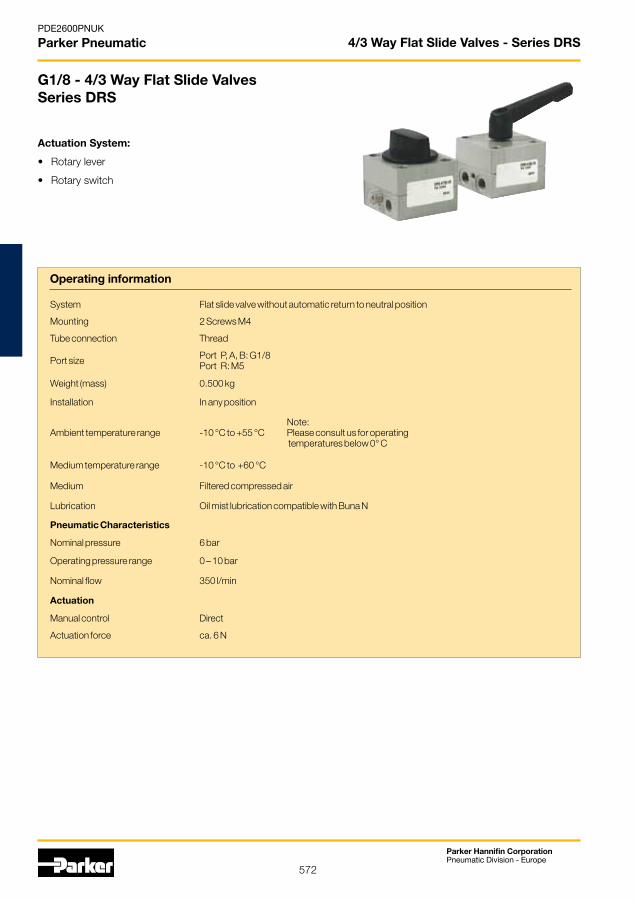
572
Parker Hannifin CorporationPneumatic Division - Europe
PDE2600PNUK
Parker Pneumatic
System Flat slide valve without automatic return to neutral position
Mounting 2 Screws M4
Tube connection Thread
Port size Port P, A, B: G1/8Port R: M5
Weight (mass) 0.500 kg
Installation In any position
Ambient temperature range -10 °C to +55 °CNote: Please consult us for operating temperatures below 0° C
Medium temperature range -10 °C to +60 °C
Medium Filtered compressed air
Lubrication Oil mist lubrication compatible with Buna N
Pneumatic Characteristics
Nominal pressure 6 bar
Operating pressure range 0 – 10 bar
Nominal flow 350 l/min
Actuation
Manual control Direct
Actuation force ca. 6 N
4/3 Way Flat Slide Valves - Series DRS
G1/8 - 4/3 Way Flat Slide ValvesSeries DRS
Actuation System:
• Rotary lever
• Rotary switch
Operating information

573
Parker Hannifin CorporationPneumatic Division - Europe
PDE2600PNUK
Parker Pneumatic
Rotary Lever – Type: DRS 412 .-1/8
Port identification:A = 4 OutletB = 2 OutletR = 5 Exhaust P = 1 Pressure supply
Rotary Switch – Type: DRS 417 .-1/8
* After removing the cover and loosening the mounting screws, the rotary switch is infinitely variable.
Angle of rotation
Swive
lling
rang
e
Angle of rotation
Order Instructions – 4/3 Way Flat Slide Valves, Series DRS
Actuation SymbolOrder Instructions
Type Order code
Rotary leverMiddle position pressurized DRS 412 B-1/8 PA 10267
Rotary leverMiddle position vented DRS 412 E-1/8 PA 10266
Rotary leverMiddle position closed DRS 412G-1/8 PA 10268
Rotary switchMiddle position pressurized DRS 417 B-1/8 PA 10264
Rotary switchMiddle position vented DRS 417 E-1/8 PA 10263
Rotary switchMiddle position closed DRS 417 G-1/8 PA 10265
A
P R
B
ba
A
P R
B
ba
A
P R
aB
b
A
P R
B
ba
A
P R
Bba
A
P R
Bba
4/3 Way Flat Slide Valves - Series DRS
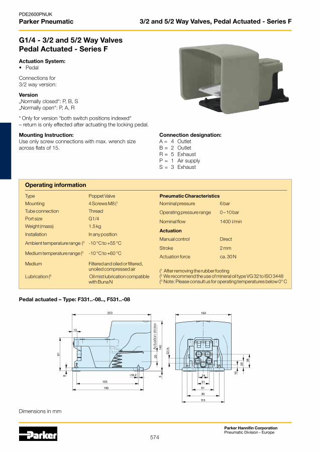
574
Parker Hannifin CorporationPneumatic Division - Europe
PDE2600PNUK
Parker Pneumatic 3/2 and 5/2 Way Valves, Pedal Actuated - Series F
Pedal actuated – Type: F331..-08.., F531..-08
Act
uatio
n st
roke
G1/4 - 3/2 and 5/2 Way ValvesPedal Actuated - Series F
Actuation System:• Pedal
Connections for3/2 way version:
Version„Normally closed“: P, B, S„Normally open“: P, A, R
* Only for version “both switch positions indexed“ – return is only effected after actuating the locking pedal.
Mounting Instruction:Use only screw connections with max. wrench size across flats of 15.
Operating information
Dimensions in mm
Connection designation:A = 4 OutletB = 2 OutletR = 5 Exhaust P = 1 Air supplyS = 3 Exhaust
Type Poppet Valve
Mounting 4 Screws M8 (1
Tube connection Thread
Port size G1/4
Weight (mass) 1.5 kg
Installation In any position
Ambient temperature range (3 -10 °C to +55 °C
Medium temperature range (3 -10 °C to +60 °C
Medium Filtered and oiled or filtered,unoiled compressed air
Lubrication (2 Oil mist lubrication compatiblewith Buna N
Pneumatic Characteristics
Nominal pressure 6 bar
Operating pressure range 0 – 10 bar
Nominal flow 1400 l/min
Actuation
Manual control Direct
Stroke 2 mm
Actuation force ca. 30 N
(1 After removing the rubber footing(2 We recommend the use of mineral oil type VG 32 to ISO 3448(3 Note: Please consult us for operating temperatures below 0° C
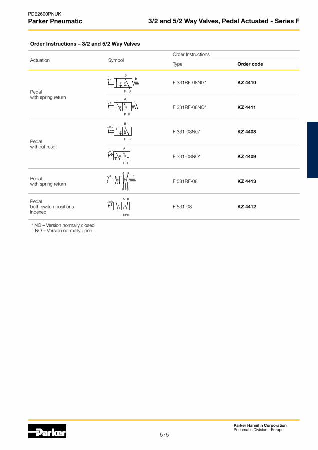
575
Parker Hannifin CorporationPneumatic Division - Europe
PDE2600PNUK
Parker Pneumatic 3/2 and 5/2 Way Valves, Pedal Actuated - Series F
Order Instructions – 3/2 and 5/2 Way Valves
Actuation SymbolOrder Instructions
Type Order code
Pedalwith spring return
F 331RF-08NG* KZ 4410
F 331RF-08NO* KZ 4411
Pedalwithout reset
F 331-08NG* KZ 4408
F 331-08NO* KZ 4409
Pedalwith spring return F 531RF-08 KZ 4413
Pedalboth switch positions indexed
F 531-08 KZ 4412
* NC – Version normally closed NO – Version normally open
B
P S
baa b
A
P R
baa b
B
P S
a,b
a b
A
P R
a,b
a b
aA
R S
B
P
ba b
a,bA
R S
B
P
a b

576
Parker Hannifin CorporationPneumatic Division - Europe
PDE2600PNUK
Parker Pneumatic 2/2 Stop Valves - Series ARKV
Actuating Pressure – Type: ARKV-40
O = pst min to openS = pst max to close
Actuating Pressure – Type: ARKV-15
O = pst min to openS = pst max to close
Actuating Pressure – Type: ARKV-20
O = pst min to openS = pst max to close
Actuating Pressure – Type: ARKV-25
O = pst min to openS = pst max to close
Actuating Pressure – Type: ARKV-50
O = pst min to openS = pst max to close
G1/2 to G2 - 2/2-Way Stop ValvesSeries ARKV
Actuation System:• Pneumatic
Operating information
Medium Compressed air, neutral gases,presswater (for low flow- und valveclosingspeed only )
Actuating medium filtered compressed air
Pneumatic characteristics
Nominal pressure 6.3 bar
Operating pressure range 0 – 10 bar
Nominal flow (l/min) 2200 5000 6900 22000 40000
Actuation
Pneumatic Direct
Port size G1/2 G3/4 G1 G1 1/2 G2
Weight (mass) Kg 0.745 1.115 1.365 2.695 4.290
Description 2/2 Way Valve
Type Poppet valve normally closed
Mounting Direct in piping
Tube connection Thread
Installation In any position
Ambient temperature range
-20 °C to +80 °C Note:Please consult usfor operatingtemperaturesbelow 0° C
Medium temperature range
0 °C to +80 °C
Dimensions in mm

577
Parker Hannifin CorporationPneumatic Division - Europe
PDE2600PNUK
Parker Pneumatic 2/2 Stop Valves - Series ARKV
Pneumatically actuated – Type: ARKV-..
Dimensions
Type A B C D E F G H
ARKV-15 NC 65 G1/2 G1/8 55 61 41.5 95 109.5
ARKV-20 NC 76 G3/4 G1/4 65 75 50 112 129
ARKV-25 NC 91 G1 G1/4 65 75 57 119 139
ARKV-40 NC 123 G11/2 G1/4 110 112 67 137 167.5
ARKV-50 NC 150 G2 G1/4 130 134 75 153 190
�
�
�� ��
Order Instructions
Actuation System SymbolOrder data
Type Order code
Pneumatic
ARKV-15 NC PD 07334
ARKV-20 NC PD 07580
ARKV-25 NC PD 07581
ARKV-40 NC PD 07757
ARKV-50 NC PD 07765
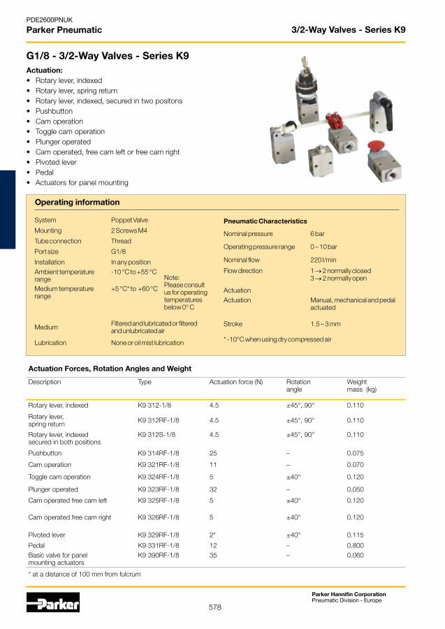
578
Parker Hannifin CorporationPneumatic Division - Europe
PDE2600PNUK
Parker Pneumatic 3/2-Way Valves - Series K9
Actuation Forces, Rotation Angles and Weight
Description Type Actuation force (N) Rotation angle
Weightmass (kg)
Rotary lever, indexed K9 312-1/8 4.5 ±45°, 90° 0.110
Rotary lever, spring return K9 312RF-1/8 4.5 ±45°, 90° 0.110
Rotary lever, indexedsecured in both positions
K9 312S-1/8 4.5 ±45°, 90° 0.110
Pushbutton K9 314RF-1/8 25 – 0.075
Cam operation K9 321RF-1/8 11 – 0.070
Toggle cam operation K9 324RF-1/8 5 ±40° 0.120
Plunger operated K9 323RF-1/8 32 – 0.050
Cam operated free cam left K9 325RF-1/8 5 ±40° 0.120
Cam operated free cam right K9 326RF-1/8 5 ±40° 0.120
Pivoted lever K9 329RF-1/8 2* ±40° 0.115
Pedal K9 331RF-1/8 12 – 0.800Basic valve for panel mounting actuators
K9 390RF-1/8 35 – 0.060
* at a distance of 100 mm from fulcrum
G1/8 - 3/2-Way Valves - Series K9Actuation:• Rotary lever, indexed• Rotary lever, spring return• Rotary lever, indexed, secured in two positons• Pushbutton• Cam operation• Toggle cam operation• Plunger operated• Cam operated, free cam left or free cam right• Pivoted lever• Pedal• Actuators for panel mounting
Operating information
System Poppet Valve
Mounting 2 Screws M4
Tube connection Thread
Port size G1/8
Installation In any positionAmbient temperature range
-10 °C to +55 °CNote: Please consult us for operating temperatures below 0° C
Medium temperature range
+5 °C* to +60 °C
Medium Filtered and lubricated or filtered and unlubricated air
Lubrication None or oil mist lubrication
Pneumatic Characteristics
Nominal pressure 6 bar
Operating pressure range 0 – 10 bar
Nominal flow 220 l/min
Flow direction 1 → 2 normally closed3 → 2 normally open
ActuationActuation Manual, mechanical and pedal
actuated
Stroke 1.5 – 3 mm
* -10°C when using dry compressed air
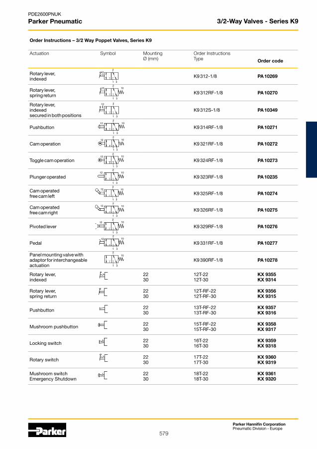
579
Parker Hannifin CorporationPneumatic Division - Europe
PDE2600PNUK
Parker Pneumatic 3/2-Way Valves - Series K9
Order Instructions – 3/2 Way Poppet Valves, Series K9
Actuation Symbol Mounting Ø (mm)
Order InstructionsType Order code
Rotary lever,indexed K9 312-1/8 PA 10269
Rotary lever,spring return K9 312RF-1/8 PA 10270
Rotary lever, indexed secured in both positions
K9 312s-1/8 PA 10349
Pushbutton K9 314RF-1/8 PA 10271
Cam operation K9 321RF-1/8 PA 10272
Toggle cam operation K9 324RF-1/8 PA 10273
Plunger operated K9 323RF-1/8 PA 10235
Cam operatedfree cam left K9 325RF-1/8 PA 10274
Cam operatedfree cam right K9 326RF-1/8 PA 10275
Pivoted lever K9 329RF-1/8 PA 10276
Pedal K9 331RF-1/8 PA 10277
Panel mounting valve withadaptor for interchangeable actuation
K9 390RF-1/8 PA 10278
Rotary lever, indexed
2230
12T-2212T-30
KX 9355KX 9314
Rotary lever,spring return
2230
12T-RF-2212T-RF-30
KX 9356KX 9315
Pushbutton 2230
13T-RF-2213T-RF-30
KX 9357KX 9316
Mushroom pushbutton 2230
15T-RF-2215T-RF-30
KX 9358KX 9317
Locking switch 2230
16T-2216T-30
KX 9359KX 9318
Rotary switch 2230
17T-2217T-30
KX 9360KX 9319
Mushroom switch Emergency shutdown
2230
18T-2218T-30
KX 9361KX 9320
2
1 3
12 10
2
1 3
1012
2
1 3
1012
2
1 3
1012
2
1 3
1012
2
1 3
1012
2
1 3
1012
2
1 3
10
2
1 3
1012
2
1 3
12
2
1 3
1012
2
1 3
12
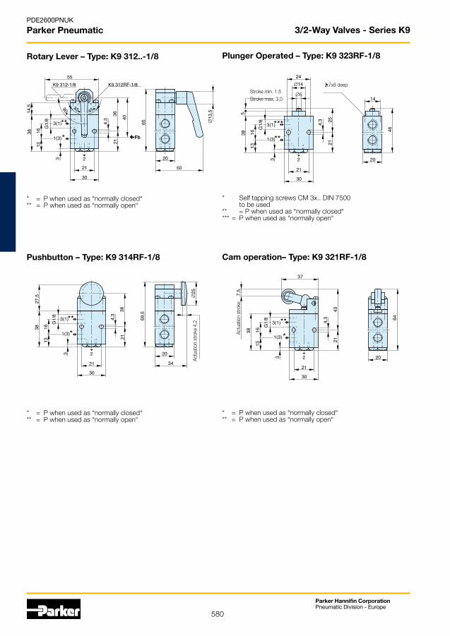
580
Parker Hannifin CorporationPneumatic Division - Europe
PDE2600PNUK
Parker Pneumatic
Rotary Lever – Type: K9 312..-1/8
* = P when used as “normally closed“** = P when used as “normally open“
Pushbutton – Type: K9 314RF-1/8
* = P when used as “normally closed“** = P when used as “normally open“
Plunger Operated – Type: K9 323RF-1/8
* Self tapping screws CM 3x.. DIN 7500 to be used** = P when used as “normally closed“*** = P when used as “normally open“
Cam operation– Type: K9 321RF-1/8
* = P when used as “normally closed“** = P when used as “normally open“
3/2-Way Valves - Series K9
Actu
atio
n st
roke
4,2
Stroke min. 1.5Stroke max. 3,0
2.7x8 deep
Actu
atio
n st
roke
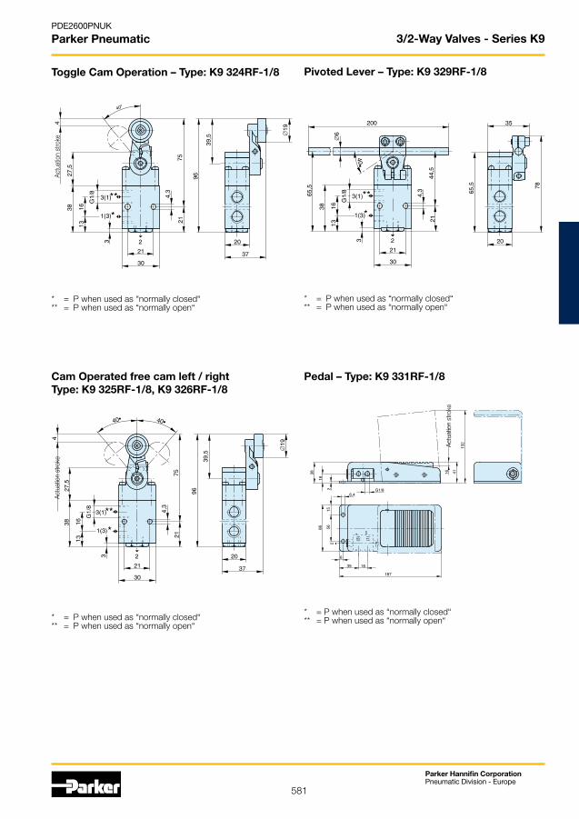
581
Parker Hannifin CorporationPneumatic Division - Europe
PDE2600PNUK
Parker Pneumatic
Toggle Cam Operation – Type: K9 324RF-1/8
* = P when used as “normally closed“** = P when used as “normally open“
Cam Operated free cam left / rightType: K9 325RF-1/8, K9 326RF-1/8
* = P when used as “normally closed“** = P when used as “normally open“
Pivoted Lever – Type: K9 329RF-1/8
* = P when used as “normally closed“** = P when used as “normally open“
Pedal – Type: K9 331RF-1/8
* = P when used as “normally closed“** = P when used as “normally open“
3/2-Way Valves - Series K9Ac
tuat
ion
stro
keAc
tuat
ion
stro
ke
Actu
atio
n st
roke
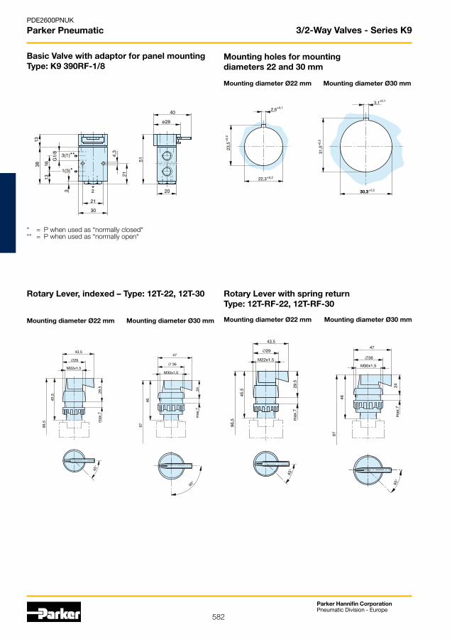
582
Parker Hannifin CorporationPneumatic Division - Europe
PDE2600PNUK
Parker Pneumatic 3/2-Way Valves - Series K9
Basic Valve with adaptor for panel mountingType: K9 390RF-1/8
* = P when used as “normally closed“** = P when used as “normally open“
Mounting holes for mountingdiameters 22 and 30 mm Mounting diameter Ø22 mm Mounting diameter Ø30 mm
Rotary Lever, indexed – Type: 12T-22, 12T-30
Mounting diameter Ø22 mm Mounting diameter Ø30 mm
Rotary Lever with spring returnType: 12T-RF-22, 12T-RF-30
Mounting diameter Ø22 mm Mounting diameter Ø30 mm

583
Parker Hannifin CorporationPneumatic Division - Europe
PDE2600PNUK
Parker Pneumatic 3/2-Way Valves - Series K9
PushbuttonType: 13T-RF-22, 13T-RF-30
Mounting diameter Ø22 mm Mounting diameter Ø30 mm
Mushroom PushbuttonType: 15T-RF-22, 15T-RF-30
Mounting diameter Ø22 mm Mounting diameter Ø30 mm
Locking SwitchType: 16T-22, 16T-30
Mounting diameter Ø22 mm Mounting diameter Ø30 mm
Rotary SwitchType: 17T-22, 17T-30
Mounting diameter Ø22 mm Mounting diameter Ø30 mm
Mushroom Switch (Emergency Shutdown) Type: 18T-22, 18T-30
Mounting diameter Ø22 mm Mounting diameter Ø30 mm

584
Parker Hannifin CorporationPneumatic Division - Europe
PDE2600PNUK
Parker Pneumatic 3/2, 5/2 and 5/3 Directional Control Valves - Series S9
Actuation: • Hand lever• Pneumatic• Electrical pilot operated• Electrical pilot operated with external pilot air• Panel mounting actuators for mounting diameter to DIN 43696
Versions:• Normally closed• Normally open• With external pilot air • With biased position • Version to ATEX Standard Note: The “normally open“ valve S9 381S-RF-1/8 cannot be used on a P-supply manifold.
S9 Series Directional Control Valves
3/2, 5/2 and 5/3 Directional Control Valves - Series S9
Actuation System Symbol Mounting Ø (mm)
Order InstructionsType
Order No.
Hand lever,indexed
S9 311-1/8 PA 10293
S9 311-1/4 PA 12708
S9 311-1/2 PA 16404
Hand lever,spring return
S9 311RF-1/8 PA 10294
S9 311RF-1/4 PA 12709
S9 311RF-1/2 PA 16405
Hand lever secured in 2 switchingpositions
S9 311S-1/4 PA 12710
S9 311S-1/2 PA 16406
Rotary lever,indexed S9 312-1/4 PA 12711
S9 312-1/2 PA 16407
Rotary lever,spring return S9 312RF-1/4 PA 12712
S9 312RF-1/2 PA 16408
Pneumatic,by permanent signal
S9 361RF-1/8 PA 10295
S9 361RF-1/4 PA 12713
S9 361RF-1/2 PA 16409
Pneumatic,by impulse
S9 361-1/8 PA 10296
S9 361-1/4 PA 12714
S9 361-1/2 PA 16410
Pneumatic, by impulse,with biased position S9 362-1/4 PA 12715
S9 362-1/2 PA 16411
Basic valve forpanel mounting
S9 390RF-1/8 PA 10307
3/2 Way Valves – Standard versions
2
1 3
12
2
1 3
12 10
2
1 3
12
2
1 3
12
2
1 3
12 10
2
1 3
12 10
2
1 3
12 10
2
1 3
12 10
2
1 3
1210

585
Parker Hannifin CorporationPneumatic Division - Europe
PDE2600PNUK
Parker Pneumatic 3/2, 5/2 and 5/3 Directional Control Valves - Series S9
Actuation System Symbol Mounting Ø (mm)
Order InstructionsType
Order No.
Rotary lever,indexed
22 12T-22 KX 9355
30 12T-30 KX 9314
Rotary lever,spring return
22 12T-RF-22 KX 9356
30 12T-RF-30 KX 9315
Pushbutton 22 13T-RF-22 KX 9357
30 13T-RF-30 KX 9316
Mushroom pushbutton 22 15T-RF-22 KX 9358
30 15T-RF-30 KX 9317
Locking switch 22 16T-22 KX 9359
30 16T-30 KX 9318
3/2 Way Valves – Standard versions
Rotary switch 22 17T-22 KX 9360
30 17T-30 KX 9319
Mushroom pushbuttonemergency-0ff
22 18T-22 KX 9361
30 18T-30 KX 9320
Electrical by permanent signal
S9 381RF-1/8-NC-.. PA 10297-..33
S9 381RF-1/4-NC-.. PA 12716-..33
S9 381RF-1/2-NC-.. PA 16412-..33
S9 381RF-1/8-NO-.. PA 10298-..33
S9 381RF-1/4-NO-.. PA 12717-..33
S9 381RF-1/2-NO-.. PA 16413-..33
with external pilot air S9 381S-RF-1/8-.. PA 10300-..33
S9 381S-RF-1/4-.. PA 12719-..33
S9 381S-RF-1/2-.. PA 16415-..33
Electrical by impulse
S9 381-1/8-.. PA 10299-..33
S9 381-1/4-.. PA 12718-..33
S9 381-1/2-.. PA 16414-..33
Electrical, by impulse,with external pilot air
S9 381S-1/8-.. PA 10301-..33
S9 381S-1/4-.. PA 12720-..33
S9 381S-1/2-.. PA 16417-..33
Electrical by impulse,with biased position S9 382-1/4-.. PA 12721-..33
S9 382-1/2-.. PA 16418-..33
with external pilot air
S9 382S-1/4-.. PA 12722-..33
S9 382S-1/2-.. PA 16419-..33
Solenoid version Nominal voltage Applicable for Key code ATEX Type additon
Standard version 230V 50/60Hz 110 V = 61 –
24V = 60V 50/60Hz 02 –
Low wattage version 24V = 13 –
230V 50/60Hz 69 –
2
1 3
1012
2
1 3
1210
12
3
2
1
14
stp
2
1 3
12 10
2
1 3
14 12
pst
2
1 3
14 12
pst
2
1 3
14 12
pst pst

586
Parker Hannifin CorporationPneumatic Division - Europe
PDE2600PNUK
Parker Pneumatic 3/2, 5/2 and 5/3 Directional Control Valves - Series S9
EX Area versions to ATEX Standard Category, type of ignition protection
Single valve: II 2G c T4 T135°C -10°C≤Ta≤+60°CSolenoid/individual use: II 2G EEx m II T5 -20°C≤Ta≤+50°CSolenoid/manifold mounting: II 2G EEx m II T5 -20°C≤Ta≤+40°C
Solenoid version Nominal voltage
Applicable for Key code ATEX Type additon
Solenoid – with cable 1.2 m
24V = 48 ATEX
– with cable 3 m 24V = 45 ATEX
– with cable 5 m 24V = 46 ATEX
– with cable 10 m 24V = 47 ATEX
– with cable 1.2 m 24V 50/60Hz 99 ATEX
– with cable 1.2 m 110V 50/60Hz 97 ATEX
– with cable 1.2 m 230V 50/60Hz 98 ATEX
Example for valves in ATEX-Version:– for valves Series S9-G1/8, S9-G1/4, S9-G1/2Please add behind the Standard Order No. “ATEX“Type: S9 381RF-1/8-NC-4633Order No. PA10297-4633ATEX

587
Parker Hannifin CorporationPneumatic Division - Europe
PDE2600PNUK
Parker Pneumatic 3/2, 5/2 and 5/3 Directional Control Valves - Series S9
Actuation System Symbol Mounting Ø (mm)
Order InstructionsType
Order No.
Hand lever,indexed
S9 511-1/8 PA 10308
S9 511-1/4 PA 12671
S9 511-1/2 PA 16367
Hand lever,spring return
S9 511RF-1/8 PA 10309
S9 511RF-1/4 PA 12672
S9 511RF-1/2 PA 16366
Hand lever secured in 2 switchingpositions
S9 511S-1/8 PA 10368
S9 511S-1/4 PA 12673
S9 511S-1/2 PA 16368
Rotary lever,indexed S9 512-1/4 PA 12674
S9 512-1/2 PA 16378
Rotary lever,spring return S9 512RF-1/4 PA 12675
S9 512RF-1/2 PA 16379
Pneumatic,by permanent signal
S9 561RF-1/8 PA 10310
S9 561RF-1/4 PA 12676
S9 561RF-1/2 PA 16165
Pneumatic,by impulse
S9 561-1/8 PA 10311
S9 561-1/4 PA 12677
S9 561-1/2 PA 16166
Pneumatic, by impulse,with biased position
S9 562-1/4 PA 12678
S9 562-1/2 PA 16167
Basic valve forpanel mounting
S9 590RF-1/8
PA 10320
Rotary lever,indexed
22 12T-22 KX 9355
30 12T-30 KX 9314
Rotary lever,spring return
22 12T-RF-22 KX 9356
30 12T-RF-30 KX 9315
Pushbutton 22 13T-RF-22 KX 9357
30 13T-RF-30 KX 9316
Mushroom pushbutton 22 15T-RF-22 KX 9358
30 15T-RF-30 KX 9317
Locking switch 22 16T-22 KX 9359
30 16T-30 KX 9318
4
5 3
142
1
14 124
5 3
2
1
4
5 3
142
1
4
5 3
142
1
14 124
5 3
2
1
144
5 3
2
1
12
14 124
5 3
2
1
14 124
5 3
2
1
1412
4
5 3
2
1
Order Instructions – 5/2 Way Valves – Standard versions
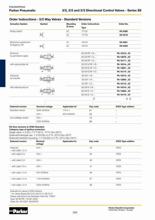
588
Parker Hannifin CorporationPneumatic Division - Europe
PDE2600PNUK
Parker Pneumatic 3/2, 5/2 and 5/3 Directional Control Valves - Series S9
Actuation System Symbol Mounting Ø (mm)
Order Instructions Order No.
Type
Rotary switch 22 17T-22 KX 9360
30 17T-30 KX 9319
Mushroom pushbuttonEmergency-Off
22 18T-22 KX 9361
30 18T-30 KX 9320
Electrical,by permanent signal
S9 581RF-1/8-.. PA 10312-..33
S9 581RF-1/4-.. PA 12679-..33
S9 581RF-1/2-.. PA 16171-..33
with external pilot air S9 581S-RF-1/8-.. PA 10314-..33
S9 581S-RF-1/4-.. PA 12681-..33
S9 581S-RF-1/2-.. PA 16174-..33
Electrical,by impulse
S9 581-1/8-.. PA 10313-..33
S9 581-1/4-.. PA 12680-..33
S9 581-1/2-.. PA 16172-..33
with external pilot air S9 581S-1/8-.. PA 10315-..33
S9 581S-1/4-.. PA 12682-..33
S9 581S-1/2-.. PA 16175-..33
Solenoid version Nominal voltage Applicable for Key code ATEX Type additon
Standard version 230V 50/60Hz 110 V = 61 –
24V = 60V 50/60Hz 02 –
Low wattage version 24V = 13 –
230V 50/60Hz 69 –
144
5 3
2
1
12
124
5 3
2
1
14
stp
4
5 3
2
1
1214
4
5 3
2
1
14 12
pst pst
EX Area versions to ATEX Standard Category, type of ignition protectionSingle valve: II 2G c T4 T135°C -10°C≤Ta≤+60°CSolenoid/individual use: II 2G EEx m II T5 -20°C≤Ta≤+50°CSolenoid/manifold mounting: II 2G EEx m II T5 -20°C≤Ta≤+40°CSolenoid version Nominal
voltageApplicable for Key code ATEX Type additon
Solenoid – with cable 1.2 m
24V = 48 ATEX
– with cable 3 m 24V = 45 ATEX
– with cable 5 m 24V = 46 ATEX
– with cable 10 m 24V = 47 ATEX
– with cable 1.2 m 24V 50/60Hz 99 ATEX
– with cable 1.2 m 110V 50/60Hz 97 ATEX
– with cable 1.2 m 230V 50/60Hz 98 ATEX
Example for valves in ATEX-Version:– for valves Series S9-G1/8, S9-G1/4, S9-G1/2Please add behind the Standard Order No. “ATEX“Type: S9 381RF-1/8-NC-4633Order No. PA10297-4633ATEX
Order Instructions - 5/2 Way Valves - Standard Versions
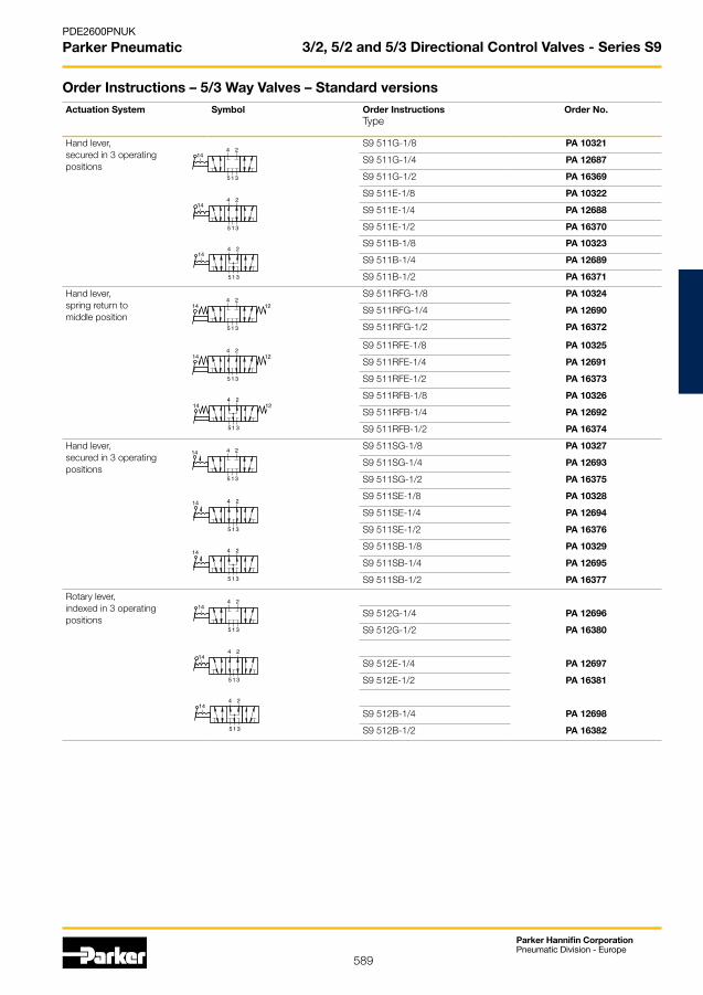
589
Parker Hannifin CorporationPneumatic Division - Europe
PDE2600PNUK
Parker Pneumatic 3/2, 5/2 and 5/3 Directional Control Valves - Series S9
Actuation System Symbol Order Instructions Type
Order No.
Hand lever,secured in 3 operatingpositions
S9 511G-1/8 PA 10321
S9 511G-1/4 PA 12687
S9 511G-1/2 PA 16369
S9 511E-1/8 PA 10322
S9 511E-1/4 PA 12688
S9 511E-1/2 PA 16370
S9 511B-1/8 PA 10323
S9 511B-1/4 PA 12689
S9 511B-1/2 PA 16371
Hand lever,spring return tomiddle position
S9 511RFG-1/8 PA 10324
S9 511RFG-1/4 PA 12690
S9 511RFG-1/2 PA 16372
S9 511RFE-1/8 PA 10325
S9 511RFE-1/4 PA 12691
S9 511RFE-1/2 PA 16373
S9 511RFB-1/8 PA 10326
S9 511RFB-1/4 PA 12692
S9 511RFB-1/2 PA 16374
Hand lever,secured in 3 operatingpositions
S9 511SG-1/8 PA 10327
S9 511SG-1/4 PA 12693
S9 511SG-1/2 PA 16375
S9 511SE-1/8 PA 10328
S9 511SE-1/4 PA 12694
S9 511SE-1/2 PA 16376
S9 511SB-1/8 PA 10329
S9 511SB-1/4 PA 12695
S9 511SB-1/2 PA 16377
Rotary lever,indexed in 3 operatingpositions
S9 512G-1/4 PA 12696
S9 512G-1/2 PA 16380
S9 512E-1/4 PA 12697
S9 512E-1/2 PA 16381
S9 512B-1/4 PA 12698
S9 512B-1/2 PA 16382
4
5 3
142
1
4
5 3
142
1
4
5 3
142
1
4
5 3
142
1
12
4
5 3
142
1
12
4
5 3
142
1
12
4
5 3
14 2
1
4
5 3
2
1
14
4
5 3
2
1
14
4
5 3
142
1
4
5 3
142
1
4
5 3
142
1
Order Instructions – 5/3 Way Valves – Standard versions
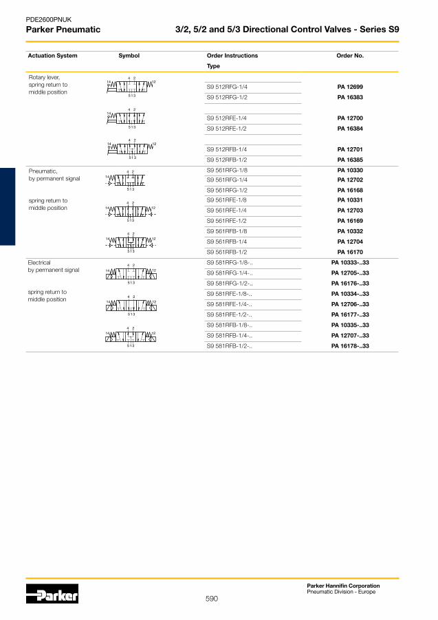
590
Parker Hannifin CorporationPneumatic Division - Europe
PDE2600PNUK
Parker Pneumatic 3/2, 5/2 and 5/3 Directional Control Valves - Series S9
Actuation System Symbol Order Instructions Order No.
Type
Rotary lever,spring return tomiddle position
S9 512RFG-1/4 PA 12699
S9 512RFG-1/2 PA 16383
S9 512RFE-1/4 PA 12700
S9 512RFE-1/2 PA 16384
S9 512RFB-1/4 PA 12701
S9 512RFB-1/2 PA 16385
Pneumatic,by permanent signal
spring return tomiddle position
S9 561RFG-1/8 PA 10330
S9 561RFG-1/4 PA 12702
S9 561RFG-1/2 PA 16168
S9 561RFE-1/8 PA 10331
S9 561RFE-1/4 PA 12703
S9 561RFE-1/2 PA 16169
S9 561RFB-1/8 PA 10332
S9 561RFB-1/4 PA 12704
S9 561RFB-1/2 PA 16170
Electricalby permanent signal
spring return tomiddle position
S9 581RFG-1/8-.. PA 10333-..33
S9 581RFG-1/4-.. PA 12705-..33
S9 581RFG-1/2-.. PA 16176-..33
S9 581RFE-1/8-.. PA 10334-..33
S9 581RFE-1/4-.. PA 12706-..33
S9 581RFE-1/2-.. PA 16177-..33
S9 581RFB-1/8-.. PA 10335-..33
S9 581RFB-1/4-.. PA 12707-..33
S9 581RFB-1/2-.. PA 16178-..33
4
5 3
2
1
14 12
4
5 3
2
1
1214
4
5 3
2
1
1214
4
5 3
2
1
14 12
4
5 3
2
1
1214
4
5 3
2
1
1214
4
5 3
142
1
12
4
5 3
142
1
12
4
5 3
142
1
12
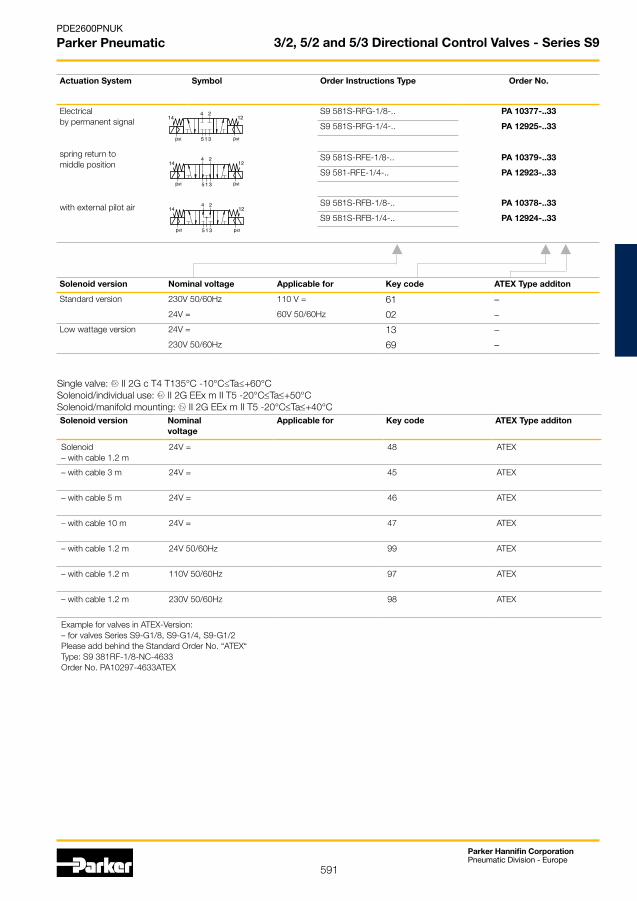
591
Parker Hannifin CorporationPneumatic Division - Europe
PDE2600PNUK
Parker Pneumatic 3/2, 5/2 and 5/3 Directional Control Valves - Series S9
Actuation System Symbol Order Instructions Type Order No.
Electricalby permanent signal
spring return tomiddle position
with external pilot air
S9 581S-RFG-1/8-.. PA 10377-..33
S9 581S-RFG-1/4-.. PA 12925-..33
S9 581S-RFE-1/8-.. PA 10379-..33
S9 581-RFE-1/4-.. PA 12923-..33
S9 581S-RFB-1/8-.. PA 10378-..33
S9 581S-RFB-1/4-.. PA 12924-..33
4
5 3
2
1pst pst
14 12
Solenoid version Nominal voltage Applicable for Key code ATEX Type additon
Standard version 230V 50/60Hz 110 V = 61 –
24V = 60V 50/60Hz 02 –
Low wattage version 24V = 13 –
230V 50/60Hz 69 –
Single valve: II 2G c T4 T135°C -10°C≤Ta≤+60°CSolenoid/individual use: II 2G EEx m II T5 -20°C≤Ta≤+50°CSolenoid/manifold mounting: II 2G EEx m II T5 -20°C≤Ta≤+40°CSolenoid version Nominal
voltageApplicable for Key code ATEX Type additon
Solenoid – with cable 1.2 m
24V = 48 ATEX
– with cable 3 m 24V = 45 ATEX
– with cable 5 m 24V = 46 ATEX
– with cable 10 m 24V = 47 ATEX
– with cable 1.2 m 24V 50/60Hz 99 ATEX
– with cable 1.2 m 110V 50/60Hz 97 ATEX
– with cable 1.2 m 230V 50/60Hz 98 ATEX
Example for valves in ATEX-Version:– for valves Series S9-G1/8, S9-G1/4, S9-G1/2Please add behind the Standard Order No. “ATEX“Type: S9 381RF-1/8-NC-4633Order No. PA10297-4633ATEX
4
5 3
2
1pst pst
14 12
4
5 3
2
1pst pst
14 12
4
5 3
2
1pst pst
14 12
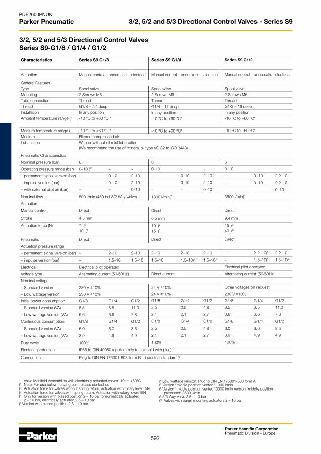
592
Parker Hannifin CorporationPneumatic Division - Europe
PDE2600PNUK
Parker Pneumatic 3/2, 5/2 and 5/3 Directional Control Valves - Series S9
Characteristics Series S9 G1/8
Actuation Manual control pneumatic electrical
General FeaturesType Spool valveMounting 2 Screws M5Tube connection ThreadThread G1/8 – 7.4 deepInstallation In any positionAmbient temperature range (1 -10 °C to +60 °C *
Medium temperature range (1 -10 °C to +60 °C *Medium Filtered compressed airLubrication With or without oil mist lubrication
(We recommend the use of mineral oil type VG 32 to ISO 3448)
Pneumatic Characteristics
Nominal pressure (bar) 6
Operating pressure range (bar) 0–10 (10 – –
– permanent signal version (bar) – 0–10 2–10
– impulse version (bar) – 0–10 2–10
– with external pilot air (bar) – – 0–10
Nominal flow 500 l/min (450 bei 3/2 Way Valve)
Actuation
Manual control Direct
Stroke 4.5 mm
Actuation force (N) 7 (2
10 (3
Pneumatic Direct
Actuation pressure range
– permanent signal version (bar) – 2–10 2–10
– impulse version (bar) – 1.5–10 1.5–10
Electrical Electrical pilot operated
Voltage type Alternating current (50/60Hz)
Nominal voltage
– Standard version 230 V ±10%
– Low wattage version 230 V ±10%
Initial power consumption G1/8 G1/4 G1/2
– Standard version (VA) 8.5 8.5 11.0
– Low wattage version (VA) 6.6 6.6 7.8
Continuous consumption G1/8 G1/4 G1/2
– Standard version (VA) 6.0 6.0 8.5
– Low wattage version (VA) 3.9 4.9 4.9
Duty cycle 100%
Electrical protection IP65 to DIN 40050 (applise only to solenoid with plug)
Connection Plug to DIN EN 175301-803 form B – industrial standard (6
* Valve Manifold Assemblies with electrically actuated valves -10 to +50°C (1 Note: For use below freezing point please contact us(2 Actuation force for valves without spring return, actuation with rotary lever: 5N(3 Actuation force for valves with spring return, Actuation with rotary lever:15N(4 Only for version with biased position 2 – 10 bar, pneumatically actuated 2 – 10 bar, electrically actuated 2.5 – 10 bar(5 Version with biased position 2.5 – 10 bar
(6 Low wattage version: Plug to DIN EN 175301-803 form A(7 Version “middle position vented“ 1000 l/min(8 Version “middle position vented“ 3300 l/min Version “middle position pressured“ 3600 l/min (9 5/3 Way Valve 2.5 – 10 bar(10 Valves with panel mounting actuators 2 – 10 bar
3/2, 5/2 and 5/3 Directional Control Valves Series S9-G1/8 / G1/4 / G1/2
Series S9 G1/4
Manual control pneumatic electrical
Spool valve2 Screws M6
Thread
G1/4 – 11 deep
In any position
-10 °C to +60 °C*
-10 °C to +60 °C*
6
0–10 – –
– 0–10 2–10
– 0–10 2–10
– – 0–10
1300 l/min(7
Direct
6.5 mm
10 (2
15 (3
Direct
2–10 2–10 2–10
1.5–10 1.5–10(4 1.5–10(4
Direct current
24 V ±10%
24 V ±10%
G1/8 G1/4 G1/2
2.5 2.5 4.8
2.1 2.1 2.7
G1/8 G1/4 G1/2
2.5 2.5 4.8
2.1 2.1 2.7
100%
Series S9 G1/2
Manual control pneumatic electrical
Spool valve2 Screws M6
Thread
G1/2 – 16 deep
In any position
-10 °C to +60 °C*
-10 °C to +60 °C*
6
0–10 – –
– 0–10 2.2–10
– 0–10 2.2–10
– – 0–10
3500 l/min(8
Direct
9.4 mm
15 (2
40 (3
Direct
– 2.2–10(9 2.2–10
– 1.5–10(5 1.5–10(4
Electrical pilot operated
Alternating current (50/60Hz)
Other voltages on request
230 V ±10%
G1/8 G1/4 G1/2
8.5 8.5 11.0
6.6 6.6 7.8
G1/8 G1/4 G1/2
6.0 6.0 8.5
3.9 4.9 4.9
100%

593
Parker Hannifin CorporationPneumatic Division - Europe
PDE2600PNUK
Parker Pneumatic 3/2, 5/2 and 5/3 Directional Control Valves - Series S9
3/2, 5/2 and 5/3 Way Valves for use in EX areas Series S9-G1/8 / G1/4 / G1/2Characteristics Series S9 G1/8
Actuation Manual Control pneumatic electrical
General Features
Type Spool valve
Mounting 2 screws M5
Tube connection Thread
Thread G1/8 – 7.4 deep
Installation In any positionAmbient temperature range (1 -10 °C to +60 °C *
Medium temperature range (1 -10 °C to +60 °C *
Medium Filtered, unlibricated compressed air – free from water and dirt to ISO8573-1
Pneumatic CharacteristicsNominal pressure (bar) 6
Operating pressure range (bar) 0–8 (10 – –
– permanent signal version (bar) – 0–8 2–8
– impulse version (bar) – 0–8 1.5–8(4
– with external pilot air (bar) – – 0–8
Nominal flow 500 l/min (450 bei 3/2 Way Valve)
Actuation
Manual control Direct
Stroke 4.5 mmActuation force (N) 7 (2
10 (3
Pneumatic Direct
Actuation pressure range– permanent signal version (bar) – 2–8 2–8
– impulse version (bar) – 1.5–8 1.5–8(4
Electrical Electrical pilot operatedCertification EC Type Test Certificate for single valve:
not required for mechanical units in II 2G
Category, type of ignition protection
Single valveII 2G c T4T135°C-10°C≤Ta≤+60°C
Voltage type Alternating current (50/60Hz)
Nominal voltage 230 V ±10%
110 V ±10%
24 V ±10%
Power rating at Un G1/8, G1/4, G1/2
3.1 VA (230V)
3.0 VA (110V)
2.5 VA (24V)
Max. power at Un (6 G1/8, G1/4, G1/2
2.9 VA (230V)
2.8 VA (110V)
2.4 VA (24V)Electrical protection IP65 (applise only to solenoid with cable)
Connection Cable – cable lengths see Order Instructions
* Valve Manifold Assemblies with electrically actuated valves -10 to +50°C (1 Note: For use below freezing point please contact us(2 Actuation force for valves without spring return, Actuation with rotary lever: 5N(3 Actuation force for valves with spring return, actuation with rotary lever: 15N(4 Only for version with biased position pneumatically actuated 2 – 8 bar, electrically actuated 2.5 – 8 bar(5 Version with biased position 2.5 – 8 bar
(6 Maximum power if warmed up to termal load limit(7 Version “middle position vented“ 1000 l/min(8 Version “middle position vented“ 3300 l/min, Version “middle position pressured“ 3600 l/min(9 5/3 Way Valve 2.5 – 8 bar(10 Valves with panel mounting actuators 2 – 8 bar
Series S9 G1/4
Manual Control pneumatic electrical
Spool valve
2 Screws M6
Thread
G1/4 – 11 deep
In any position -10 °C to +60 °C *
-10 °C to +60 °C *
Solids: Class 7 particle size <40 µm for gas Water content: pressure dew point + 3°C, Class 4, but at least 5°C below minimum operatingtemperature
6
0–8 – –
– 0–8 2–8
– 0–8 1.5–8(4
– – 0–8
1300 l/min (7
Direct
6.5 mm10 (2
15 (3
Direct
2–8 2–8 2–8
1.5–8 1.5–8(4 1.5–8(4
EC Type Test Certificate for solenoid:PTB-No. 03 Ex IEC 2019X and PTB 03 ATEX 2018X toT5Solenoid/individual use: II 2G EEx m II T5 -20°C≤Ta≤+50°CSolenoid/manifold mounting: II 2G EEx m II T5 -20°C≤Ta≤+40°CDirect current
24 V ±10%
G1/8, G1/4, G1/2
3.3 VA (24V)
G1/8, G1/4, G1/2
3.0 VA (24V)
Series S9 G1/2
Manual Control pneumatic electrical
Spool valve
2 Screws M6
Thread
G1/2 – 16 deep
In any position-10 °C to +60 °C *
-10 °C to +60 °C *
Solids: Class 7 particle size <40 µm for gas Water content: pressure dew point + 3°C, Class 4, but at least 5°C below minimum o perating temperature
6
0–8 – –
– 0–8 2.2–8
– 0–8 1.5–8(4
– – 0–8
3500 l/min (8
Direct
9.4 mm15 (2
40 (3
Direct
– 2.2–8(9 2.2–8
– 1.5–8(5 1.5–8(4
EC Type Test Certificate for solenoid:PTB-No. 03 Ex IEC 2019X and PTB 03 ATEX 2018X toT5
Solenoid/individual use:II 2G EEx m II T5 -20°C≤Ta≤+50°CSolenoid/manifold mounting:II 2G EEx m II T5 -20°C≤Ta≤+40°C
Other voltages on request

594
Parker Hannifin CorporationPneumatic Division - Europe
PDE2600PNUK
Parker Pneumatic 3/2, 5/2 and 5/3 Directional Control Valves - Series S9
Possible combinations: Actuation System (14)
Actuation System (12)
Basic valves
Actuation Systems: Pneumatic AND OR TIMER• Electrical pilot operated
Versions:• Freely selectable types • See Order information • All Timer-Versions on request
Valve Combinations with Logic Elements3/2, 5/2 and 5/3 Way Valves
* RFG = middle position closed RFE = middle position exhausted RFB = middle position pressurized
Dimension Table and adjustment ranges
Adjustment range [s] Dimension A [mm]
0.1 to 15 103 (133*)0.1 to 30 117 (147*)0.1 to 60 150 (180*)
* Version with rotary knob (optional)
Dimension Table and adjustment ranges
Adjustment range [s] Dimension A [mm]
0.1 to 15 103 (133*)0.1 to 30 117 (147*)0.1 to 60 150 (180*)
* Version with rotary knob (optional)
PneumaticActuation 61
ORActuation 63
ANDActuation 65
5/2 and 5/3 Way Valves3/2 Way Valve
PneumaticActuation 61
ORActuation System 63
ANDActuation 65
TimerActuation 64
Standard version: Countersunk adjustment screw
On request: Rotary knob version
TimerActuation 64
Standard version: Countersunk adjustment screw
On request: Rotary knob version
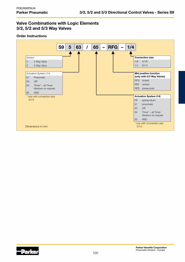
595
Parker Hannifin CorporationPneumatic Division - Europe
PDE2600PNUK
Parker Pneumatic 3/2, 5/2 and 5/3 Directional Control Valves - Series S9
S9 5 63 / 65 – RFG – 1/4
Version
3 3 Way Valve
5 5 Way Valve
Actuation System (14)
61 Pneumatic
63 OR
64 Timer* – all Timer- Versions on request
65 AND
* only with connection size G1/4
Connection size
1/8 G1/8
1/4 G1/4
Mid position function(only with 5/3 Way Valves)
RFG closed
RFE vented
RFB pressurized
Actuation System (14)
RF spring return
61 pneumatic
63 OR
64 Timer* – all Timer- Versions on request
65 AND
* only with Connection size G1/4
Order Instructions
Dimensions in mm
Valve Combinations with Logic Elements3/2, 5/2 and 5/3 Way Valves

596
Parker Hannifin CorporationPneumatic Division - Europe
PDE2600PNUK
Parker Pneumatic
3/2 Way Lever Operated Valves
G1/4 Safety hand lever actuatedType: S9 311S-1/4
G1/4 Hand lever actuatedType: S9 311-1/4, S9 311RF-1/4
G1/2 Hand lever actuatedType: S9 311-1/2, S9 311RF-1/2
G1/2 Safety hand lever actuatedType: S9 311S-1/2
G1/8 Hand lever actuatedType: S9 311-1/8, S9 311RF-1/8

597
Parker Hannifin CorporationPneumatic Division - Europe
PDE2600PNUK
Parker Pneumatic
5/2 Way Lever Operated Valves
G1/4 Safety hand lever actuatedType: S9 511S-1/4
G1/4 Hand lever actuatedType: S9 511-1/4, S9 511RF-1/4
G1/2 Hand lever actuatedType: S9 511-1/2, S9 511RF-1/2
G1/2 Safety hand lever actuatedType: S9 511S-1/2
G1/8 Hand lever actuatedType: S9 511-1/8, S9 511RF-1/8
G1/8 Safety Hand lever actuatedType: S9 511S.-1/8
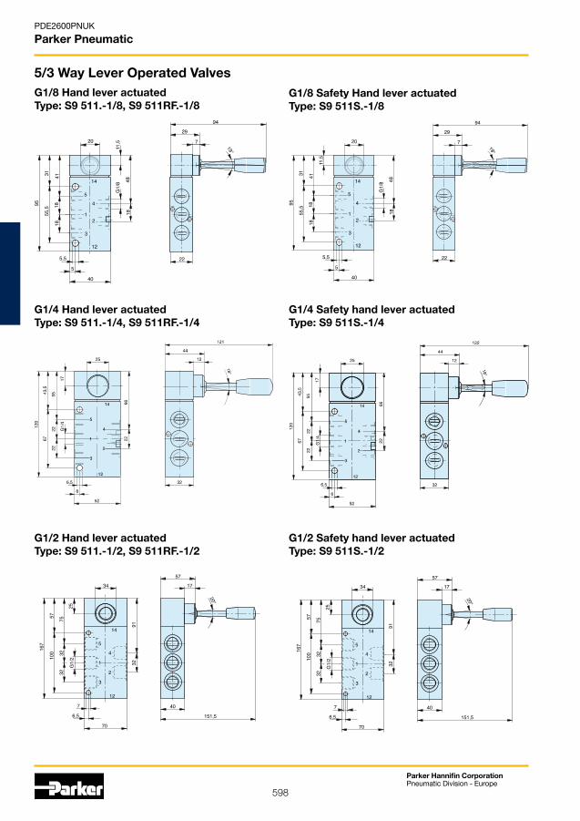
598
Parker Hannifin CorporationPneumatic Division - Europe
PDE2600PNUK
Parker Pneumatic
5/3 Way Lever Operated Valves
G1/4 Safety hand lever actuatedType: S9 511S.-1/4
G1/4 Hand lever actuatedType: S9 511.-1/4, S9 511RF.-1/4
G1/2 Hand lever actuatedType: S9 511.-1/2, S9 511RF.-1/2
G1/2 Safety hand lever actuatedType: S9 511S.-1/2
G1/8 Hand lever actuatedType: S9 511.-1/8, S9 511RF.-1/8
G1/8 Safety Hand lever actuatedType: S9 511S.-1/8

599
Parker Hannifin CorporationPneumatic Division - Europe
PDE2600PNUK
Parker Pneumatic
Pneumatically actuatedType: S9 361-1/8, S9 361RF-1/8
Electrically actuatedType: S9 381(S)-1/8, S9 381(S)RF-1/8
* Manual override** Operating pressure supply pst only for type S9 381S*** Solenoid width = 30 mm on low wattage coil version
only for type
only for type
S9361-1/8
Solenoid for use in EX areas – Dimensions
X = 15,5 mm
Cable lenth see Order Instructions
Solenoid width 30 mm
Dimensions in mm
3/2, 5/2 and 5/3 Directional Control Valves - Series S9
G1/8 - 3/2 Way Valves
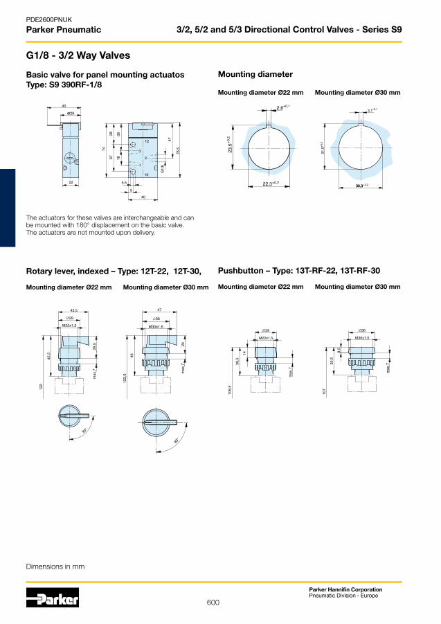
600
Parker Hannifin CorporationPneumatic Division - Europe
PDE2600PNUK
Parker Pneumatic
Basic valve for panel mounting actuatosType: S9 390RF-1/8
The actuators for these valves are interchangeable and can be mounted with 180° displacement on the basic valve.The actuators are not mounted upon delivery.
Mounting diameter
Mounting diameter Ø22 mm Mounting diameter Ø30 mm
Rotary lever, indexed – Type: 12T-22, 12T-30,
Mounting diameter Ø22 mm Mounting diameter Ø30 mm
Pushbutton – Type: 13T-RF-22, 13T-RF-30
Mounting diameter Ø22 mm Mounting diameter Ø30 mm
3/2, 5/2 and 5/3 Directional Control Valves - Series S9
G1/8 - 3/2 Way Valves
Dimensions in mm

601
Parker Hannifin CorporationPneumatic Division - Europe
PDE2600PNUK
Parker Pneumatic
Mushroom pushbuttonType: 15T-RF-22, 15T-RF-30
Mounting diameter Ø22 mm Mounting diameter Ø30 mm
Rotary lever with spring returnType: 12T-RF-22, 12T-RF-30
Mounting diameter Ø22 mm Mounting diameter Ø30 mm
Mushroom pushbutton emergency-0ffType: 18T-22, 18T-30
Mounting diameter Ø22 mm Mounting diameter Ø30 mm
Rotary switch – Type: 17T-22, 17T-30
Mounting diameter Ø22 mm Mounting diameter Ø30 mm
Locking switchType: 16T-22, 16T-30
Mounting diameter Ø22 mm Mounting diameter Ø30 mm
3/2, 5/2 and 5/3 Directional Control Valves - Series S9
G1/8 - 3/2 Way Valves
Dimensions in mm

602
Parker Hannifin CorporationPneumatic Division - Europe
PDE2600PNUK
Parker Pneumatic
Pneumatically actuated Type: S9 361-1/4, S9 362-1/4, S9 361RF-1/4
Rotary lever actuatedType: S9 312-1/4, S9 312RF-1/4
only for typeS9 361-1/4S9 362-1/4
Electrically actuated – Type: S9 381(S)-1/4, S9 382(S)-1/4,S9 381(S)RF-1/4
* Manual override** Operating pressure supply pst only for type S9 381S*** Solenoid width = 30 mm on low wattage coil version
Note:The “normally open“ valve S9 381S-RF-1/4 cannot be used on a P-supply manifold.
only for type
X = 15.5 mm
Cable lenth see Order Instructions
Solenoid width 30 mm
Solenoid for use in EX areasDimensions
3/2, 5/2 and 5/3 Directional Control Valves - Series S9
G1/4 - 3/2 Way Valves
Dimensions in mm

603
Parker Hannifin CorporationPneumatic Division - Europe
PDE2600PNUK
Parker Pneumatic
Pneumatically actuatedType: S9 361-1/2, S9 361RF-1/2
Rotary lever actuatedType: S9 312-1/2, S9 312RF-1/2
only for typeS9 361-1/2S9 362-1/2
6 de
ep
Electrically actuatedType: S9 381(S)-1/2, S9 382(S)-1/2,S9 381(S)RF-1/2
* Manual override** Operating pressure supply pst only for type S9 381S*** Solenoid width = 30 mm on low wattage coil version
Note:The “normally open“ valve S9 381S-RF-1/2 cannot be used on a P-supply manifold.
6 de
ep
only for typeS9 581(S)-1/2S9 582(S)-1/2
Solenoid for use in EX areasDimensions
X = 21 mm
Cable lenth see Order Instructions
Solenoid width 30 mm
3/2, 5/2 and 5/3 Directional Control Valves - Series S9
G1/2 - 3/2 Way Valves
Dimensions in mm
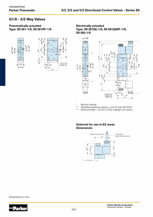
604
Parker Hannifin CorporationPneumatic Division - Europe
PDE2600PNUK
Parker Pneumatic
Pneumatically actuatedType: S9 561-1/8, S9 561RF-1/8
only for type
Electrically actuatedType: S9 581(S)-1/8, S9 581(S)RF-1/8,S9 582-1/8
* Manual override** Operating pressure supply pst only for type S9 581S*** Solenoid width = 30 mm on low wattage coil version
only for type
X = 15,5 mm
Cable lenth see Order Instructions
Solenoid width 30 mm
3/2, 5/2 and 5/3 Directional Control Valves - Series S9
G1/8 - 5/2 Way Valves
Dimensions in mm
Solenoid for use in EX areasDimensions

605
Parker Hannifin CorporationPneumatic Division - Europe
PDE2600PNUK
Parker Pneumatic
Basic valve for panel mounting actuatosType: S9 590RF-1/8
The actuators for these valves are interchangeable and can be mounted with 180° displacement on the basic valve.The actuators are not mounted upon delivery.
Rotary lever, indexedType: 12T-22, 12T-30
Mounting diameter Ø22 mm Mounting diameter Ø30 mm
Mounting diameter Mounting diameter Ø22 mm Mounting diameter Ø30 mm
Pushbutton – Type: 13T-RF-22, 13T-RF-30
Mounting diameter Ø22 mm Mounting diameter Ø30 mm
Mushroom pushbuttonType: 15T-RF-22, 15T-RF-30
Mounting diameter Ø22 mm Mounting diameter Ø30 mm
3/2, 5/2 and 5/3 Directional Control Valves - Series S9
G1/8 - 5/2 Way Valves
Dimensions in mm

606
Parker Hannifin CorporationPneumatic Division - Europe
PDE2600PNUK
Parker Pneumatic
Rotary lever with spring returnType: 12T-RF-22, 12T-RF-30
Mounting diameter Ø22 mm Mounting diameter Ø30 mm
Locking switchType: 16T-22, 16T-30
Mounting diameter Ø22 mm Mounting diameter Ø30 mm
Rotary switchType: 17T-22, 17T-30
Mounting diameter Ø22 mm Mounting diameter Ø30 mm
Mushroom pushbutton emergency-0ffType: 18T-22, 18T-30
Mounting diameter Ø22 mm Mounting diameter Ø30 mm
3/2, 5/2 and 5/3 Directional Control Valves - Series S9
G1/8 - 5/2 Way Valves
Dimensions in mm

607
Parker Hannifin CorporationPneumatic Division - Europe
PDE2600PNUK
Parker Pneumatic
Rotary lever actuated Type: S9 512-1/4, S9 512RF-1/4
Pneumatically actuatedType: S9 561-1/4, S9 562-1/4, S9 561RF-1/4
Electrically actuatedType: S9 581(S)-1/4, S9 582(S)-1/4,S9 581(S)RF-1/4
* Manual override** Operating pressure supply pst only for type S9 581S*** Solenoid width = 30 mm on low wattage coil version
only for type
S9 561-1/4S9 562-1/4
only for
type
Solenoid for use in EX areasDimensions
X = 15,5 mm
Cable lenth see Order Instructions
Solenoid width 30 mm
3/2, 5/2 and 5/3 Directional Control Valves - Series S9
G1/4 - 5/2 Way Valves
Dimensions in mm

608
Parker Hannifin CorporationPneumatic Division - Europe
PDE2600PNUK
Parker Pneumatic
Rotary lever actuatedType: S9 512-1/2, S9 512RF-1/2
Pneumatically actuatedType: S9 561-1/2, S9 561RF-1/2, S9 562-1/2
Electrically actuatedType: S9 581(S)-1/2, S9 582-1/2,S9 581(S)RF-1/2
* Manual override** Operating pressure supply pst only for type S9 581S*** Solenoid width is 30 mm on low wattage coil version
Solenoid for use in EX areasDimensions
X = 21 mm
Cable lenth see Order Instructions
Solenoid width 30 mm
only for typeS9 561-1/2S9 562-1/2
6 de
ep
only for typeS9 581-1/2S9 582-1/2S9 581S-1/2
6 de
ep
3/2, 5/2 and 5/3 Directional Control Valves - Series S9
G1/2 - 5/2 Way Valves
Dimensions in mm

609
Parker Hannifin CorporationPneumatic Division - Europe
PDE2600PNUK
Parker Pneumatic
Pneumatically actuatedType: S9 561RF.-1/8
Solenoid for use in EX areasDimensions
X = 15,5 mm
Cable lenth see Order Instructions
Solenoid width 30 mm
pst ***
pst ***
Electrically actuatedType: S9 581(S-)RF.-1/8
* Manual override** Solenoid width = 30 mm on low wattage coil version*** Operating pressure supply pst only for type S9 581S
3/2, 5/2 and 5/3 Directional Control Valves - Series S9
G1/8 - 5/3 Way Valves
Dimensions in mm

610
Parker Hannifin CorporationPneumatic Division - Europe
PDE2600PNUK
Parker Pneumatic
Rotary lever actuatedType: S9 512.-1/4, S9 512RF.-1/4
Pneumatically actuatedType: S9 561RF.-1/4
Electrically actuatedType: S9 581RF.-1/4
* Manual override** Solenoid width is 30 mm on low wattage coil version
Solenoid for use in EX areasDimensions
3/2, 5/2 and 5/3 Directional Control Valves - Series S9
G1/4 - 5/3 Way Valves
Dimensions in mm
X = 15,5 mm
Cable lenth see Order Instructions
Solenoid width 30 mm
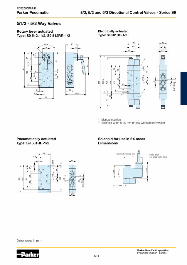
611
Parker Hannifin CorporationPneumatic Division - Europe
PDE2600PNUK
Parker Pneumatic
Rotary lever actuatedType: S9 512.-1/2, S9 512RF.-1/2
Pneumatically actuated Type: S9 561RF.-1/2
Electrically actuatedType: S9 581RF.-1/2
* Manual override** Solenoid width is 30 mm on low wattage coil version
6 de
ep
Solenoid for use in EX areasDimensions
X = 21 mm
Cable lenth see Order Instructions
Solenoid width 30 mm
6 de
ep
3/2, 5/2 and 5/3 Directional Control Valves - Series S9
G1/2 - 5/3 Way Valves
Dimensions in mm

612
Parker Hannifin CorporationPneumatic Division - Europe
PDE2600PNUK
Parker Pneumatic
Pneumatic oscillating – Type: S9 568/68-1/4-SO
Type Spool valve
Mounting 2 Screws M6 (M4)
Tube connection Thread
Connection size G1/4, 11 deep
Weight (mass) 0.65 kg
Installation In any position
Ambient temperature range **
-10 °C to +60 °C
Medium temperature range **
-10 °C to +60 °C
Medium Filtered and oiled or filtered, unoiled compressed air
5/2-Way Oscillating Valves - Series S9
�
� �
�
�
��
5/2-Way Oscillating Valves
The oscillating valve generates oscillating movements such as e.g. shaking, hammering, plunging, feed motions etc.
Function:If compressed air is intro-ducesed into inlet port 1, the outlet ports 4 and 2 are alternately supplied with compressed air.
The speed of the operated cylinder and also the strokefrequency are adjusted with two exhaust air throttles.
Operating information
Lubrication * None or oil mist lubrication
Pneumatic Characteristics
Nominal pressure 6 bar
Operating pressure range 3 – 8 bar
Nominal flow 1300 l/min
Actuation
Pneumatic Direct
Actuation pressure range 3 – 8 bar
* We recommend the use of mineral oil type VG 32 to ISO 3448** Note: Please consult us for operating temperatures below 0° C
Dimensions in mm
Symbol Type Order Code
S9 568/68-1/4-SO PD 34796
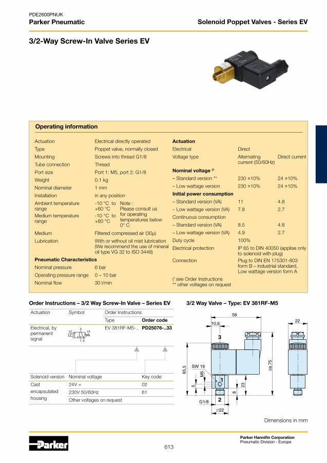
613
Parker Hannifin CorporationPneumatic Division - Europe
PDE2600PNUK
Parker Pneumatic
Lubrication * None or oil mist lubrication
Pneumatic Characteristics
Nominal pressure 6 bar
Operating pressure range 3 – 8 bar
Nominal flow 1300 l/min
Actuation
Pneumatic Direct
Actuation pressure range 3 – 8 bar
* We recommend the use of mineral oil type VG 32 to ISO 3448** Note: Please consult us for operating temperatures below 0° C
3/2 Way Valve – Type: EV 381RF-M5
Solenoid Poppet Valves - Series EV
3/2-Way Screw-In Valve Series EV
Operating information
Actuation Electrical directly operated
Type Poppet valve, normally closed
Mounting Screws into thread G1/8
Tube connection Thread
Port size Port 1: M5, port 2: G1/8
Weight 0.1 kg
Nominal diameter 1 mm
Installation in any position
Ambient temperature range
-10 °C to +60 °C
Note : Please consult us for operating temperatures below 0° C
Medium temperature range
-10 °C to +60 °C
Medium Filtered compressed air (30µ)
Lubrication With or without oil mist lubrication (We recommend the use of mineral oil type VG 32 to ISO 3448)
Pneumatic Characteristics
Nominal pressure 6 bar
Operating pressure range 0 – 10 bar
Nominal flow 30 l/min
Actuation
Electrical Direct
Voltage type Alternating current (50/60Hz)
Direct current
Nominal voltage (1
– Standard version ** 230 ±10% 24 ±10%
– Low wattage version 230 ±10% 24 ±10%
Initial power consumption
– Standard version (VA) 11 4.8
– Low wattage version (VA) 7.8 2.7
Continuous consumption
– Standard version (VA) 8.5 4.8
– Low wattage version (VA) 4.9 2.7
Duty cycle 100%
Electrical protection IP 65 to DIN 40050 (applise only to solenoid with plug)
Connection Plug to DIN EN 175301-803 form B – industrial standard, Low wattage version form A
(1 see Order Instructions** other voltages on request
Dimensions in mm
21012
1 3
Actuation Symbol Order Instructions
Type Order code
Electrical, by permanentsignal
EV 381RF-M5-.. PD25076-..33
Solenoid version Nominal voltage Key code
Castencapsulated housing
24V = 02
230V 50/60Hz 61
Other voltages on request
Order Instructions – 3/2 Way Screw-In Valve – Series EV
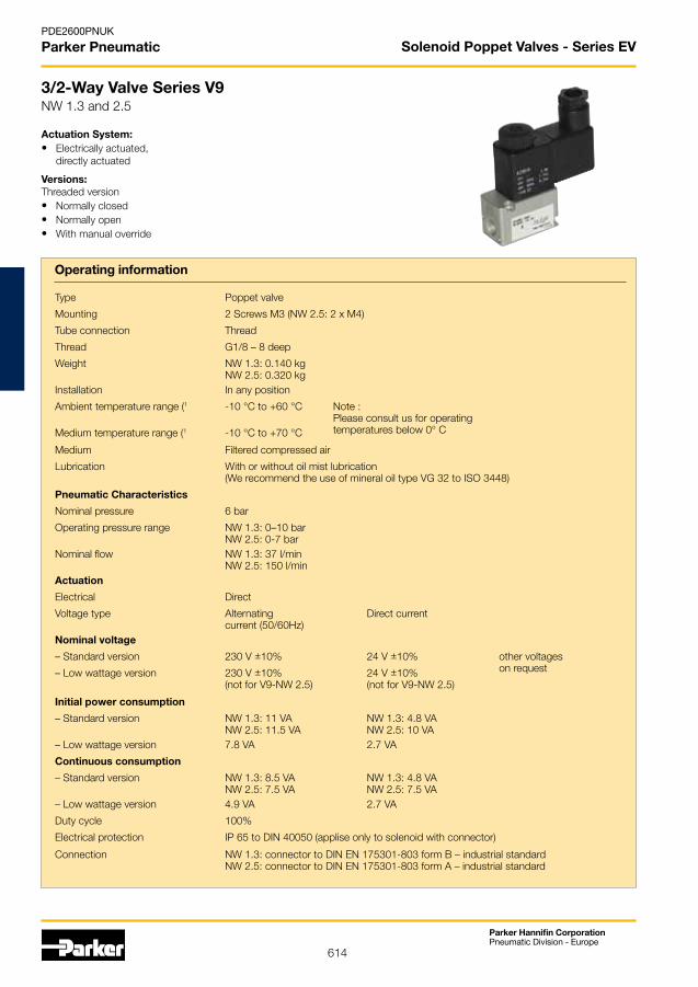
614
Parker Hannifin CorporationPneumatic Division - Europe
PDE2600PNUK
Parker Pneumatic Solenoid Poppet Valves - Series EV
3/2-Way Valve Series V9NW 1.3 and 2.5
Operating information
Actuation System:• Electrically actuated, directly actuated
Versions:Threaded version• Normally closed• Normally open• With manual override
Type Poppet valve
Mounting 2 Screws M3 (NW 2.5: 2 x M4)
Tube connection Thread
Thread G1/8 – 8 deep
Weight NW 1.3: 0.140 kgNW 2.5: 0.320 kg
Installation In any position
Ambient temperature range (1 -10 °C to +60 °C Note : Please consult us for operating temperatures below 0° C Medium temperature range (1 -10 °C to +70 °C
Medium Filtered compressed air
Lubrication With or without oil mist lubrication (We recommend the use of mineral oil type VG 32 to ISO 3448)
Pneumatic Characteristics
Nominal pressure 6 bar
Operating pressure range NW 1.3: 0–10 barNW 2.5: 0-7 bar
Nominal flow NW 1.3: 37 l/minNW 2.5: 150 l/min
Actuation
Electrical Direct
Voltage type Alternating current (50/60Hz)
Direct current
Nominal voltage
– Standard version 230 V ±10% 24 V ±10% other voltageson request– Low wattage version 230 V ±10%
(not for V9-NW 2.5)24 V ±10%(not for V9-NW 2.5)
Initial power consumption
– Standard version NW 1.3: 11 VA NW 2.5: 11.5 VA
NW 1.3: 4.8 VANW 2.5: 10 VA
– Low wattage version 7.8 VA 2.7 VA
Continuous consumption
– Standard version NW 1.3: 8.5 VANW 2.5: 7.5 VA
NW 1.3: 4.8 VANW 2.5: 7.5 VA
– Low wattage version 4.9 VA 2.7 VA
Duty cycle 100%
Electrical protection IP 65 to DIN 40050 (applise only to solenoid with connector)
Connection NW 1.3: connector to DIN EN 175301-803 form B – industrial standard NW 2.5: connector to DIN EN 175301-803 form A – industrial standard
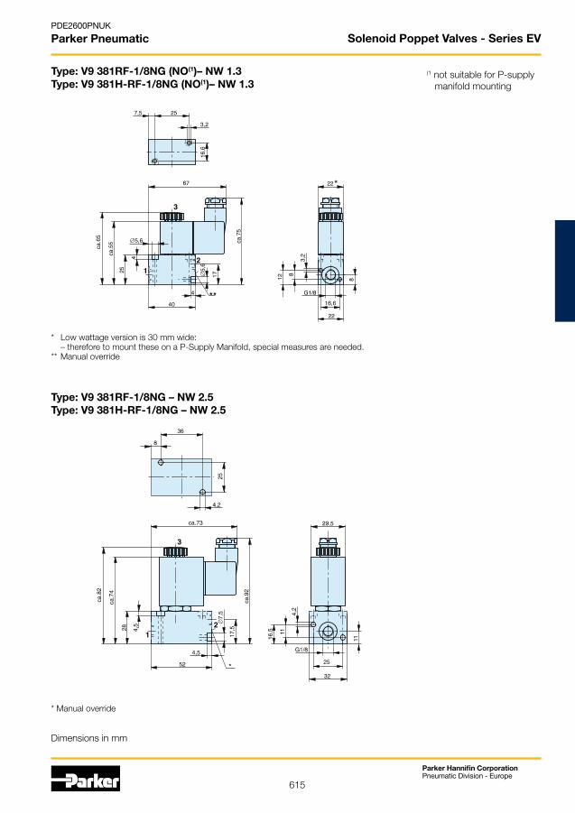
615
Parker Hannifin CorporationPneumatic Division - Europe
PDE2600PNUK
Parker Pneumatic
Type: V9 381RF-1/8NG (NO(1)– NW 1.3Type: V9 381H-RF-1/8NG (NO(1)– NW 1.3
* Low wattage version is 30 mm wide: – therefore to mount these on a P-Supply Manifold, special measures are needed.** Manual override
Type: V9 381RF-1/8NG – NW 2.5Type: V9 381H-RF-1/8NG – NW 2.5
* Manual override
(1 not suitable for P-supply manifold mounting
Solenoid Poppet Valves - Series EV
Dimensions in mm

616
Parker Hannifin CorporationPneumatic Division - Europe
PDE2600PNUK
Parker Pneumatic
Order Instructions – Accessories for P-Supply Manifold Mounting
Description for NW Order No.
P-Manifold PL-1/8-.. 1.3 PD32763-....*
P-Manifold PLK-1/8-.. 1.3 PD37174-....*
P-Manifold PL-1/4-.. 2.5 PD32765-....*
P-Manifold PLK-1/4-.. 2.5 PD32175-....*
* Complete order no. with no. of valve
The delivery includes:
P-Manifold complete incl. mounting kit
2
1 3
12 10
2
1 3
12 10
21012
1 3
Order Instructions – 3/2 Way Valves – Series V9Actuation System Symbol Nominal
Size(mm)
Order InstructionsType Order code
Electrical, by permanent signal
NW 1.3 V9 381RF-1/8-NC-.. PA 10362-..33
NW 2.5 V9 381RF-1/8-NC-.. PA 10369-..33
NW 1.3 V9 381H-RF-1/8-NC-.. PA 10363-..33
NW 2.5 V9 381H-RF-1/8-NC-.. PA 10370-..33
NW 1.3 V9 381H-RF-1/8-NO-.. PA 10367-..33
Solenoid version Nominal voltage Applicable for Key code
Standard version230V 50/60Hz 110 V = 61
24V = 60V 50/60Hz 02
Low wattage version24V = 13
230V 50/60Hz 69
Other voltages on request
Solenoid Poppet Valves - Series EV
617
Parker Hannifin CorporationPneumatic Division - Europe
PDE2600PNUK
Parker Pneumatic
Air Preparation &Airline Accessories
Air Preparation & Airline Accessories
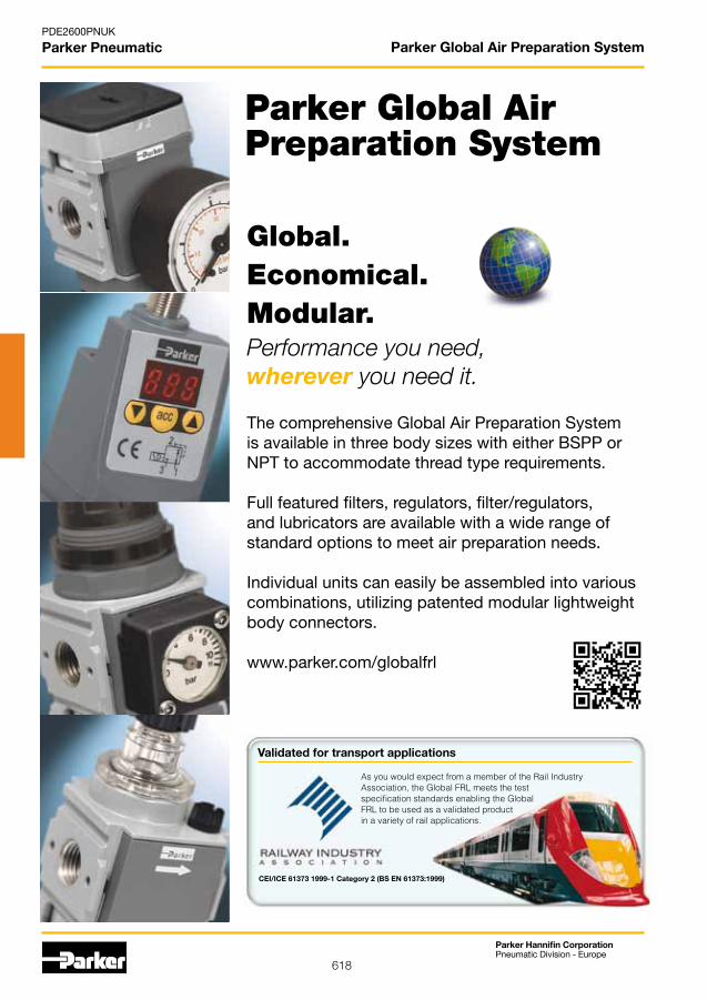
618
Parker Hannifin CorporationPneumatic Division - Europe
PDE2600PNUK
Parker Pneumatic Parker Global Air Preparation System
Parker Global Air Preparation System
Global.Economical.Modular.Performance you need, wherever you need it.
The comprehensive Global Air Preparation System is available in three body sizes with either BSPP or NPT to accommodate thread type requirements.
Full featured filters, regulators, filter/regulators, and lubricators are available with a wide range of standard options to meet air preparation needs.
Individual units can easily be assembled into various combinations, utilizing patented modular lightweight body connectors.
www.parker.com/globalfrl
Validated for transport applications
As you would expect from a member of the Rail Industry Association, the Global FRL meets the testspecification standards enabling the GlobalFRL to be used as a validated productin a variety of rail applications.
CEI/ICE 61373 1999-1 Category 2 (BS EN 61373:1999)
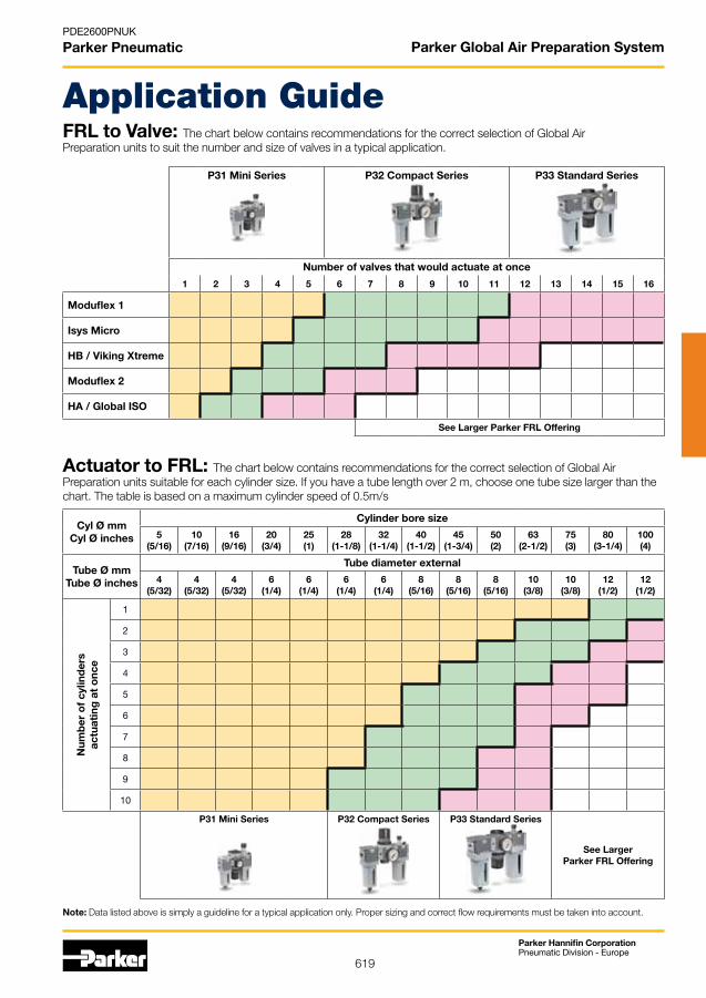
619
Parker Hannifin CorporationPneumatic Division - Europe
PDE2600PNUK
Parker Pneumatic
FRL to Valve: The chart below contains recommendations for the correct selection of Global Air Preparation units to suit the number and size of valves in a typical application.
Actuator to FRL: The chart below contains recommendations for the correct selection of Global Air Preparation units suitable for each cylinder size. If you have a tube length over 2 m, choose one tube size larger than the chart. The table is based on a maximum cylinder speed of 0.5m/s
P31 Mini Series P32 Compact Series P33 Standard Series
Number of valves that would actuate at once
1 2 3 4 5 6 7 8 9 10 11 12 13 14 15 16
Moduflex 1
Isys Micro
HB / Viking Xtreme
Moduflex 2
HA / Global ISO
See Larger Parker FRL Offering
Note: Data listed above is simply a guideline for a typical application only. Proper sizing and correct flow requirements must be taken into account.
Cyl Ø mm Cyl Ø inches
Cylinder bore size
5(5/16)
10(7/16)
16(9/16)
20(3/4)
25(1)
28(1-1/8)
32(1-1/4)
40(1-1/2)
45(1-3/4)
50(2)
63(2-1/2)
75(3)
80(3-1/4)
100(4)
Tube Ø mm Tube Ø inches
Tube diameter external
4 (5/32)
4 (5/32)
4 (5/32)
6 (1/4)
6 (1/4)
6 (1/4)
6 (1/4)
8 (5/16)
8 (5/16)
8 (5/16)
10 (3/8)
10 (3/8)
12 (1/2)
12 (1/2)
1
2
3
4
5
6
7
8
9
10
P31 Mini Series P32 Compact Series P33 Standard Series
See Larger Parker FRL Offering
Num
ber
of
cylin
der
sac
tuat
ing
at
onc
eApplication Guide
Parker Global Air Preparation System
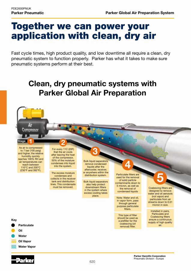
620
Parker Hannifin CorporationPneumatic Division - Europe
PDE2600PNUK
Parker Pneumatic Parker Global Air Preparation System
Together we can power your application with clean, dry air
As air is compressedto 7 bar (100 psig)
and higher, the relative humidity quickly
reaches 100% RH and air temperatures can
reach between 110°C and 200°C (230°F and 392°F).
For every 11C (20F) that the air cools
after leaving the heat of the compressor,
50% of the moisture condenses into liquid
into the system.
The excess moisture condenses and
collects in the receiver tank and distribution
lines. This condensate must be removed.
Bulk liquid separators remove condensed
liquids after the aftercooler, receiver,
or anywhere within the distribution system.
Bulk liquid separators also help protect
downstream filters in the system where excess cooling takes
place.
Particulate filters are used for the removal
of solid particle contaminants down to
5 micron, as well as the removal of
condensed liquidsCoalescing filters are designed to remove
water and oil aerosols (not vapor) and
particulate from air streams down to 0.01
micron in size.
Note: Water and oil, in vapor form, pass
through general purpose particulate
filters.
This type of filter should be used as a prefilter for the coalescing (oil removal) filter.
Installed in pairs, Particulate and
Coalescing filters ensure a continuous supply of high quality
air.
Key
Particulate
Oil
Water
Oil Vapor
Water Vapor
1Stage 23
45
Fast cycle times, high product quality, and low downtime all require a clean, dry pneumatic system to function properly. Parker has what it takes to make sure pneumatic systems perform at their best.
Clean, dry pneumatic systems withParker Global Air Preparation
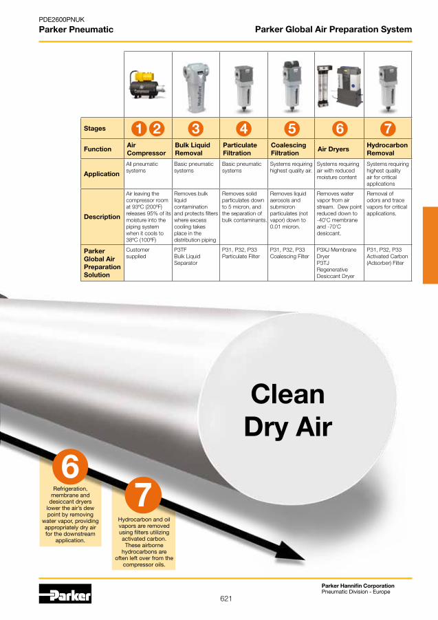
621
Parker Hannifin CorporationPneumatic Division - Europe
PDE2600PNUK
Parker Pneumatic Parker Global Air Preparation System
Refrigeration, membrane and
desiccant dryers lower the air’s dew point by removing
water vapor, providing appropriately dry air for the downstream
application.
Hydrocarbon and oil vapors are removed using filters utilizing activated carbon.These airborne
hydrocarbons are often left over from the
compressor oils.
67
CleanDry Air
Stages
FunctionAir Compressor
Bulk Liquid Removal
Particulate Filtration
Coalescing Filtration
Air DryersHydrocarbon Removal
Application
All pneumatic systems
Basic pneumatic systems
Basic pneumatic systems
Systems requiring highest quality air.
Systems requiring air with reduced moisture content
Systems requiring highest quality air for critical applications
Description
Air leaving the compressor room at 93ºC (200ºF) releases 95% of its moisture into the piping system when it cools to 38ºC (100ºF)
Removes bulk liquid contamination and protects filters where excess cooling takes place in the distribution piping
Removes solid particulates down to 5 micron, and the separation of bulk contaminants.
Removes liquid aerosols and submicron particulates (not vapor) down to 0.01 micron.
Removes water vapor from air stream. Dew point reduced down to -40'C membrane and -70'C desiccant.
Removal of odors and trace vapors for critical applications.
Parker Global Air Preparation Solution
Customer supplied
P3TF Bulk Liquid Separator
P31, P32, P33 Particulate Filter
P31, P32, P33 Coalescing Filter
P3XJ Membrane Dryer P3TJ Regenerative Desiccant Dryer
P31, P32, P33 Activated Carbon (Adsorber) Filter
431 2 5 76

622
Parker Hannifin CorporationPneumatic Division - Europe
PDE2600PNUK
Parker Pneumatic ATEX Certification

623
Parker Hannifin CorporationPneumatic Division - Europe
PDE2600PNUK
Parker Pneumatic
Validated for transport applications
CEI/ICE 61373 1999-1 Category 2 (BS EN 61373:1999)
Railway Industry Association
• TheuseofaportblockkitandT-bracketshouldbeusedatalltimes (angle / L-brackets should not be used in rail applications)
• Additionalsecurityisrecomendedwiththeuseof‘vibrationproofadhesive’ on the wall mounting screws to the port / connector block
• Inlet(P1)andOutlet(P2)portsshouldalwayshaveaT-Bracketfixationto eliminate product canterlever stress
• ‘L’bracketsshouldnotbeusedintheuseforrailservice
Recommended mounting / fixation method for use in transportation applications.
Position of T-Brackets for multiple units
1 2 3 4 5
For illustration purposes only
As you would expect from a member of the Rail Industry Association, Global air preparation meets the test specification standards enabling theGlobal series to be used as a validated productin a variety of rail applications.
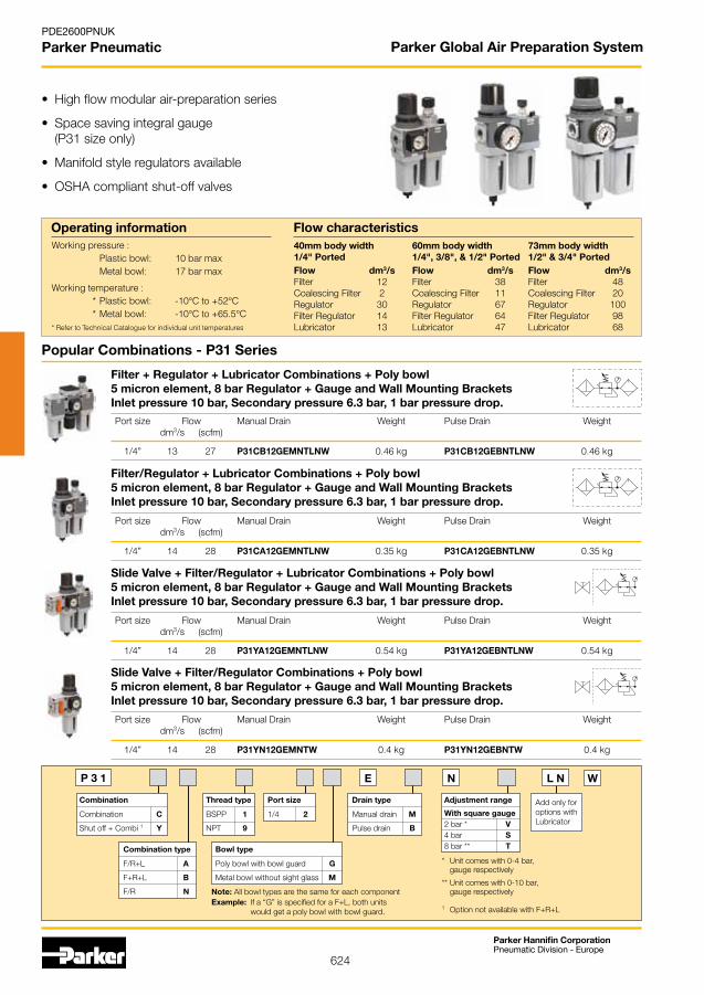
624
Parker Hannifin CorporationPneumatic Division - Europe
PDE2600PNUK
Parker Pneumatic Parker Global Air Preparation System
Operating information Working pressure : Plastic bowl: 10 bar max Metal bowl: 17 bar max
Working temperature : * Plastic bowl: -10°C to +52°C * Metal bowl: -10°C to +65.5°C* Refer to Technical Catalogue for individual unit temperatures
Flow characteristics
• Highflowmodularair-preparationseries
• Spacesavingintegralgauge (P31 size only)
• Manifoldstyleregulatorsavailable
• OSHAcompliantshut-offvalves
40mm body width1/4" PortedFlow dm3/sFilter 12 Coalescing Filter 2 Regulator 30Filter Regulator 14 Lubricator 13
60mm body width1/4", 3/8", & 1/2" PortedFlow dm3/sFilter 38 Coalescing Filter 11 Regulator 67Filter Regulator 64 Lubricator 47
73mm body width1/2" & 3/4" PortedFlow dm3/sFilter 48 Coalescing Filter 20 Regulator 100Filter Regulator 98 Lubricator 68
Popular Combinations - P31 Series
Filter + Regulator + Lubricator Combinations + Poly bowl5 micron element, 8 bar Regulator + Gauge and Wall Mounting BracketsInlet pressure 10 bar, Secondary pressure 6.3 bar, 1 bar pressure drop.
Filter/Regulator + Lubricator Combinations + Poly bowl5 micron element, 8 bar Regulator + Gauge and Wall Mounting BracketsInlet pressure 10 bar, Secondary pressure 6.3 bar, 1 bar pressure drop.
Port size Flow Manual Drain Weight Pulse Drain Weight dm3/s (scfm)
1/4” 13 27 P31CB12GEMNTLNW 0.46 kg P31CB12GEBNTLNW 0.46 kg
Slide Valve + Filter/Regulator + Lubricator Combinations + Poly bowl5 micron element, 8 bar Regulator + Gauge and Wall Mounting BracketsInlet pressure 10 bar, Secondary pressure 6.3 bar, 1 bar pressure drop.
Slide Valve + Filter/Regulator Combinations + Poly bowl5 micron element, 8 bar Regulator + Gauge and Wall Mounting BracketsInlet pressure 10 bar, Secondary pressure 6.3 bar, 1 bar pressure drop.
P 3 1
Thread type
BSPP 1
NPT 9
Port size
1/4 2
Bowl type
Poly bowl with bowl guard G
Metal bowl without sight glass M
Drain type
Manual drain M
Pulse drain B
Combination
Combination C
Shut off + Combi 1 Y
Adjustment range
With square gauge2 bar * V4 bar S8 bar ** T
* Unit comes with 0-4 bar, gauge respectively
** Unit comes with 0-10 bar, gauge respectively
1 OptionnotavailablewithF+R+L
Combination type
F/R+L A
F+R+L B
F/R N Note: All bowl types are the same for each componentExample: If a “G” is specified for a F+L, both units would get a poly bowl with bowl guard.
E N L N W
Add only foroptions withLubricator
Port size Flow Manual Drain Weight Pulse Drain Weight dm3/s (scfm)
1/4” 14 28 P31CA12GEMNTLNW 0.35 kg P31CA12GEBNTLNW 0.35 kg
Port size Flow Manual Drain Weight Pulse Drain Weight dm3/s (scfm)
1/4” 14 28 P31YA12GEMNTLNW 0.54 kg P31YA12GEBNTLNW 0.54 kg
Port size Flow Manual Drain Weight Pulse Drain Weight dm3/s (scfm)
1/4” 14 28 P31YN12GEMNTW 0.4 kg P31YN12GEBNTW 0.4 kg
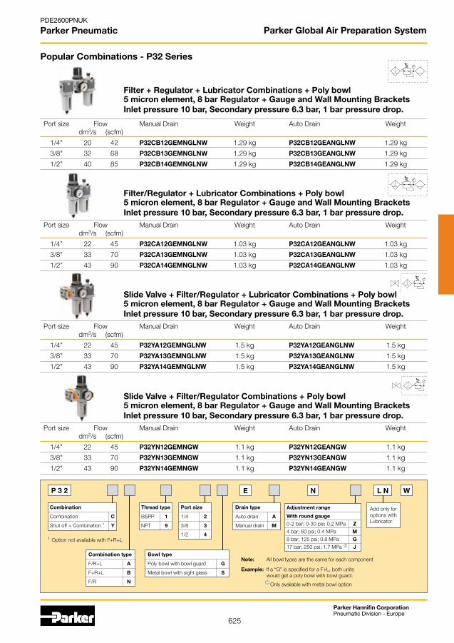
625
Parker Hannifin CorporationPneumatic Division - Europe
PDE2600PNUK
Parker Pneumatic Parker Global Air Preparation System
Popular Combinations - P32 Series
Filter + Regulator + Lubricator Combinations + Poly bowl5 micron element, 8 bar Regulator + Gauge and Wall Mounting BracketsInlet pressure 10 bar, Secondary pressure 6.3 bar, 1 bar pressure drop.
Filter/Regulator + Lubricator Combinations + Poly bowl5 micron element, 8 bar Regulator + Gauge and Wall Mounting BracketsInlet pressure 10 bar, Secondary pressure 6.3 bar, 1 bar pressure drop.
Port size Flow Manual Drain Weight Auto Drain Weight dm3/s (scfm)
1/4” 20 42 P32CB12GEMNGLNW 1.29 kg P32CB12GEANGLNW 1.29 kg
3/8” 32 68 P32CB13GEMNGLNW 1.29 kg P32CB13GEANGLNW 1.29 kg
1/2” 40 85 P32CB14GEMNGLNW 1.29 kg P32CB14GEANGLNW 1.29 kg
Port size Flow Manual Drain Weight Auto Drain Weight dm3/s (scfm)
1/4” 22 45 P32CA12GEMNGLNW 1.03 kg P32CA12GEANGLNW 1.03 kg
3/8” 33 70 P32CA13GEMNGLNW 1.03 kg P32CA13GEANGLNW 1.03 kg
1/2” 43 90 P32CA14GEMNGLNW 1.03 kg P32CA14GEANGLNW 1.03 kg
Slide Valve + Filter/Regulator + Lubricator Combinations + Poly bowl5 micron element, 8 bar Regulator + Gauge and Wall Mounting BracketsInlet pressure 10 bar, Secondary pressure 6.3 bar, 1 bar pressure drop.
Port size Flow Manual Drain Weight Auto Drain Weight dm3/s (scfm)
1/4” 22 45 P32YA12GEMNGLNW 1.5 kg P32YA12GEANGLNW 1.5 kg
3/8” 33 70 P32YA13GEMNGLNW 1.5 kg P32YA13GEANGLNW 1.5 kg
1/2” 43 90 P32YA14GEMNGLNW 1.5 kg P32YA14GEANGLNW 1.5 kg
Slide Valve + Filter/Regulator Combinations + Poly bowl5 micron element, 8 bar Regulator + Gauge and Wall Mounting BracketsInlet pressure 10 bar, Secondary pressure 6.3 bar, 1 bar pressure drop.
Port size Flow Manual Drain Weight Auto Drain Weight dm3/s (scfm)
1/4” 22 45 P32YN12GEMNGW 1.1 kg P32YN12GEANGW 1.1 kg
3/8” 33 70 P32YN13GEMNGW 1.1 kg P32YN13GEANGW 1.1 kg
1/2” 43 90 P32YN14GEMNGW 1.1 kg P32YN14GEANGW 1.1 kg
Thread type
BSPP 1
NPT 9
Port size
1/4 2
3/8 3
1/2 4
Bowl type
Poly bowl with bowl guard G
Metal bowl with sight glass S
Drain type
Auto drain A
Manual drain M
Combination type
F/R+L A
F+R+L B
F/R N
E N L N W
Add only foroptions withLubricator
P 3 2
Combination
Combination C
Shut off + Combination 1 Y
1 OptionnotavailablewithF+R+L
Adjustment range
With round gauge
0-2 bar; 0-30 psi; 0.2 MPa Z
4 bar; 60 psi; 0.4 MPa M
8 bar; 125 psi; 0.8 MPa G
17 bar; 250 psi; 1.7 MPa 2 J
Note: All bowl types are the same for each component
Example: If a “G” is specified for a F+L, both units would get a poly bowl with bowl guard.
2 Onlyavailablewithmetalbowloption
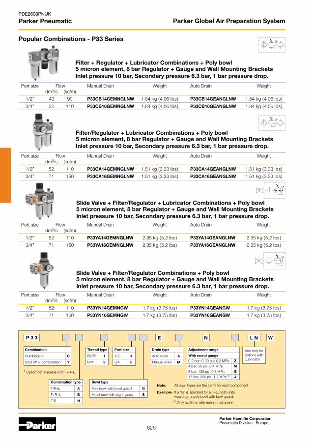
626
Parker Hannifin CorporationPneumatic Division - Europe
PDE2600PNUK
Parker Pneumatic Parker Global Air Preparation System
Popular Combinations - P33 Series
Filter + Regulator + Lubricator Combinations + Poly bowl5 micron element, 8 bar Regulator + Gauge and Wall Mounting BracketsInlet pressure 10 bar, Secondary pressure 6.3 bar, 1 bar pressure drop.
Filter/Regulator + Lubricator Combinations + Poly bowl5 micron element, 8 bar Regulator + Gauge and Wall Mounting BracketsInlet pressure 10 bar, Secondary pressure 6.3 bar, 1 bar pressure drop.
Port size Flow Manual Drain Weight Auto Drain Weight dm3/s (scfm)
1/2” 52 110 P33CA14GEMNGLNW 1.51 kg (3.33 lbs) P33CA14GEANGLNW 1.51 kg (3.33 lbs)
3/4” 71 150 P33CA16GEMNGLNW 1.51 kg (3.33 lbs) P33CA16GEANGLNW 1.51 kg (3.33 lbs)
Port size Flow Manual Drain Weight Auto Drain Weight dm3/s (scfm)
1/2” 43 90 P33CB14GEMNGLNW 1.84 kg (4.06 lbs) P33CB14GEANGLNW 1.84 kg (4.06 lbs)
3/4” 52 110 P33CB16GEMNGLNW 1.84 kg (4.06 lbs) P33CB16GEANGLNW 1.84 kg (4.06 lbs)
Slide Valve + Filter/Regulator + Lubricator Combinations + Poly bowl5 micron element, 8 bar Regulator + Gauge and Wall Mounting BracketsInlet pressure 10 bar, Secondary pressure 6.3 bar, 1 bar pressure drop.
Port size Flow Manual Drain Weight Auto Drain Weight dm3/s (scfm)
1/2” 52 110 P33YA14GEMNGLNW 2.35 kg (5.2 lbs) P33YA14GEANGLNW 2.35 kg (5.2 lbs)
3/4” 71 150 P33YA16GEMNGLNW 2.35 kg (5.2 lbs) P33YA16GEANGLNW 2.35 kg (5.2 lbs)
Slide Valve + Filter/Regulator Combinations + Poly bowl5 micron element, 8 bar Regulator + Gauge and Wall Mounting BracketsInlet pressure 10 bar, Secondary pressure 6.3 bar, 1 bar pressure drop.
Port size Flow Manual Drain Weight Auto Drain Weight dm3/s (scfm)
1/2” 52 110 P33YN14GEMNGW 1.7 kg (3.75 lbs) P33YN14GEANGW 1.7 kg (3.75 lbs)
3/4” 71 150 P33YN16GEMNGW 1.7 kg (3.75 lbs) P33YN16GEANGW 1.7 kg (3.75 lbs)
P 3 3
Thread type
BSPP 1
NPT 9
Port size
1/2 4
3/4 6
Bowl type
Poly bowl with bowl guard G
Metal bowl with sight glass S
Drain type
Auto drain A
Manual drain M
Adjustment range
With round gauge
0-2 bar; 0-30 psi; 0.2 MPa Z
4 bar; 60 psi; 0.4 MPa M
8 bar; 125 psi; 0.8 MPa G
17 bar; 250 psi; 1.7 MPa 2 JCombination type
F/R+L A
F+R+L B
F/R N
Note: All bowl types are the same for each component
Example: If a “G” is specified for a F+L, both units would get a poly bowl with bowl guard.
E N L N W
Add only foroptions withLubricator
Combination
Combination C
Shut off + Combination 1 Y
1 OptionnotavailablewithF+R+L
2 Onlyavailablewithmetalbowloption

627
Parker Hannifin CorporationPneumatic Division - Europe
PDE2600PNUK
Parker Pneumatic Parker Global Air Preparation System
4mm (5/32")I.D. TubeBarb fitting
Bowlremovalclearance
35(1.38)
80(3.15)
41(1.61)
40(1.57)
77(3.03)
35(1.38)
164.1(6.46)
33.3(1.31)
4mm (5/32")I.D. TubeBarb fitting
Bowlremovalclearance
35(1.38)
120(4.72)
41(1.61)
40(1.57)
40(1.57)
77(3.03)
35(1.38)
155.2(6.11)
33.3(1.31)
129(5.08)
47.1(1.85)
115(4.53)
64.5(2.54)
254(10.0)
100(3.94)
50(3.94)
41(1.6)
4.8 mm (.19)I.D. TubeBarb fitting
Bowlremovalclearance.(Manual andAuto Drain.)
198(7.80)
47.1(1.85)
115(4.53)
69(2.72)
64.5(2.54)
100(3.94)
50(3.94)
4.8 mm (.19)I.D. TubeBarb fitting
222(10.0)
41(1.6)
Bowlremovalclearance.(Manual andAuto Drain.)
77.5(3.05)
155(6.10)
120(4.72)
47.1(1.85)
100(3.94)
50(3.94)
4.8 mm (.19)I.D. TubeBarb fitting
Bowlremovalclearance.(Manual andAuto Drain.)
291(11.44)
51(2.00)
82(3.23)
77.5(3.05)
237(9.33)
238(9.37)
100(3.94)
50(3.94)
51(2.00)
4.8 mm (.19)I.D. TubeBarb fitting
Bowlremovalclearance.(Manual andAuto Drain.)
4mm (5/32")I.D. TubeBarb fitting
Bowlremovalclearance
35(1.38)
80(3.15)
41(1.61)
40(1.57)
77(3.03)
35(1.38)
164.1(6.46)
33.3(1.31)
4mm (5/32")I.D. TubeBarb fitting
Bowlremovalclearance
35(1.38)
120(4.72)
41(1.61)
40(1.57)
40(1.57)
77(3.03)
35(1.38)
155.2(6.11)
33.3(1.31)
129(5.08)
47.1(1.85)
115(4.53)
64.5(2.54)
254(10.0)
100(3.94)
50(3.94)
41(1.6)
4.8 mm (.19)I.D. TubeBarb fitting
Bowlremovalclearance.(Manual andAuto Drain.)
198(7.80)
47.1(1.85)
115(4.53)
69(2.72)
64.5(2.54)
100(3.94)
50(3.94)
4.8 mm (.19)I.D. TubeBarb fitting
222(10.0)
41(1.6)
Bowlremovalclearance.(Manual andAuto Drain.)
77.5(3.05)
155(6.10)
120(4.72)
47.1(1.85)
100(3.94)
50(3.94)
4.8 mm (.19)I.D. TubeBarb fitting
Bowlremovalclearance.(Manual andAuto Drain.)
291(11.44)
51(2.00)
82(3.23)
77.5(3.05)
237(9.33)
238(9.37)
100(3.94)
50(3.94)
51(2.00)
4.8 mm (.19)I.D. TubeBarb fitting
Bowlremovalclearance.(Manual andAuto Drain.)
Popular Combination Dimensions - mm (inches)
P31
P32
P33
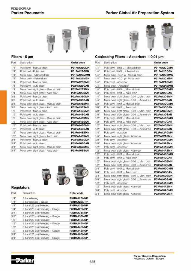
628
Parker Hannifin CorporationPneumatic Division - Europe
PDE2600PNUK
Parker Pneumatic Parker Global Air Preparation System
Regulators
Port Description Order code 1/4” 8 bar relieving P31RA12BNNP1/4” 8 bar relieving + gauge P31RA12BNTP1/4” 8 bar (125 psi) Relieving P32RA12BNNP1/4” 8 bar (125 psi) Relieving + Gauge P32RA12BNGP 3/8” 8 bar (125 psi) Relieving P32RA13BNNP3/8” 8 bar (125 psi) Relieving + Gauge P32RA13BNGP1/2” 8 bar (125 psi) Relieving P32RA14BNNP1/2” 8 bar (125 psi) Relieving + Gauge P32RA14BNGP1/2” 8 bar (125 psi) Relieving P33RA14BNNP1/2” 8 bar (125 psi) Relieving + Gauge P33RA14BNGP3/4” 8 bar (125 psi) Relieving P33RA16BNNP3/4” 8 bar (125 psi) Relieving + Gauge P33RA16BNGP
Filters - 5 µm Coalescing Filters + Absorbers - 0,01 µm
Port Description Order code 1/4” Poly bowl - Manual drain P31FA12EGMN1/4” Poly bowl - Pulse drain P31FA12EGBN1/4” Metal bowl - Manual drain P31FA12EMMN1/4” Metal bowl - Pulse drain P31FA12EMBN1/4 Poly bowl - Manual drain P32FA12EGMN1/4 Poly bowl - Auto drain P32FA12EGAN1/4 Metal bowl sight glass - Manual drain P32FA12ESMN1/4 Metal bowl sight glass - Auto drain P32FA12ESAN 3/8 Poly bowl - Manual drain P32FA13EGMN3/8 Poly bowl - Auto drain P32FA13EGAN3/8 Metal bowl sight glass - Manual drain P32FA13ESMN3/8 Metal bowl sight glass - Auto drain P32FA13ESAN1/2 Poly bowl - Manual drain P32FA14EGMN1/2 Poly bowl - Auto drain P32FA14EGAN1/2 Metal bowl sight glass - Manual drain P32FA14ESMN1/2 Metal bowl sight glass - Auto drain P32FA14ESAN1/2” Poly bowl - Manual drain P33FA14EGMN1/2” Poly bowl - Auto drain P33FA14EGAN1/2” Metal bowl sight glass - Manual drain P33FA14ESMN1/2” Metal bowl sight glass - Auto drain P33FA14ESAN3/4” Poly bowl - Manual drain P33FA16EGMN3/4” Poly bowl - Auto drain P33FA16EGAN3/4” Metal bowl sight glass - Manual drain P33FA16ESMN3/4” Metal bowl sight glass - Auto drain P33FA16ESAN
Port Description Order code 1/4” Poly bowl - 0.01 µ - Manual drain P31FA12CGMN1/4” Poly bowl - 0.01 µ - Pulse drain P31FA12CGBN1/4” Metal bowl - 0.01 µ - Manual drain P31FA12CMMN1/4” Metal bowl - 0.01 µ - Pulse drain P31FA12CMBN1/4” Poly bowl - Adsorber P31FA12AGMN1/4” Metal bowl - Adsorber P31FA12AMMN1/4” Poly bowl - 0.01 µ, Manual drain P32FA12DGMN1/4” Poly bowl - 0.01 µ, Auto drain P32FA12DGAN1/4” Metal bowl sight glass - 0.01 µ, Man. drain P32FA12DSMN1/4” Metal bowl sight glass - 0.01 µ, Auto drain P32FA12DSAN 3/8” Poly bowl - 0.01 µ, Manual drain P32FA13DGMN3/8” Poly bowl - 0.01 µ, Auto drain P32FA13DGAN3/8” Metal bowl sight glass - 0.01 µ, Man. drain P32FA13DSMN3/8” Metal bowl sight glass - 0.01 µ, Auto drain P32FA13DSAN1/2” Poly bowl - 0.01 µ, Manual drain P32FA14DGMN1/2” Poly bowl - 0.01 µ, Auto drain P32FA14DGAN1/2” Metal bowl sight glass - 0.01 µ, Man. drain P32FA14DSMN1/2” Metal bowl sight glass - 0.01 µ, Auto drain P32FA14DSAN1/4” Poly bowl - Adsorber P32FA12AGMN1/4” Metal bowl sight glass - Adsorber P32FA12ASMN3/8” Poly bowl - Adsorber P32FA13AGMN3/8” Metal bowl sight glass - Adsorber P32FA13ASMN1/2” Poly bowl - Adsorber P32FA14AGMN1/2” Metal bowl sight glass - Adsorber P32FA14ASMN1/2” Poly bowl - 0.01 µ, Manual drain P33FA14DGMN1/2” Poly bowl - 0.01 µ, Auto drain P33FA14DGAN1/2” Metal bowl sight glass - 0.01 µ, Man. drain P33FA14DSMN1/2” Metal bowl sight glass - 0.01 µ, Auto drain P33FA14DSAN3/4” Poly bowl - 0.01 µ, Manual drain P33FA16DGMN3/4” Poly bowl - 0.01 µ, Auto drain P33FA16DGAN3/4” Metal bowl sight glass - 0.01 µ, Man. drain P33FA16DSMN3/4” Metal bowl sight glass - 0.01 µ, Auto drain P33FA16DSAN1/2” Poly bowl - Adsorber P33FA14AGMN1/2” Metal bowl sight glass - Adsorber P33FA14ASMN3/4” Poly bowl - Adsorber P33FA16AGMN3/4” Metal bowl sight glass - Adsorber P33FA16ASMN

629
Parker Hannifin CorporationPneumatic Division - Europe
PDE2600PNUK
Parker Pneumatic Parker Global Air Preparation System
Filter Regulators - (P31) pressures 2 & 4 bar (P32/P33) pressures 2,4 & 17 bar available.
Lubricators
Port Description Order code
1/4” 8 bar (125 psi) Relieving - Poly bowl - Manual drain P31EA12EGMBNTP
1/4” 8 bar (125 psi) Relieving - Poly bowl - Pulse drain P31EA12EGBBNTP
1/4” 8 bar (125 psi) Relieving - Metal bowl - Manual drain P31EA12EMMBNTP
1/4” 8 bar (125 psi) Relieving - Metal bowl - Pulse drain P31EA12EMBBNTP
1/4” 8 bar (125 psi) Relieving - Poly bowl - Manual drain P32EA12EGMBNGP
1/4” 8 bar (125 psi) Relieving - Poly bowl - Auto drain P32EA12EGABNGP
1/4” 8 bar (125 psi) Relieving - Metal bowl sight glass - Manual drain P32EA12ESMBNGP
1/4” 8 bar (125 psi) Relieving - Metal bowl sight glass - Auto drain P32EA12ESABNGP
3/8” 8 bar (125 psi) Relieving - Poly bowl - Manual drain P32EA13EGMBNGP
3/8” 8 bar (125 psi) Relieving - Poly bowl - Auto drain P32EA13EGABNGP
3/8” 8 bar (125 psi) Relieving - Metal bowl sight glass - Manual drain P32EA13ESMBNGP
3/8” 8 bar (125 psi) Relieving - Metal bowl sight glass - Auto drain P32EA13ESABNGP
1/2” 8 bar (125 psi) Relieving - Poly bowl - Manual drain P32EA14EGMBNGP
1/2” 8 bar (125 psi) Relieving - Poly bowl - Auto drain P32EA14EGABNGP
1/2” 8 bar (125 psi) Relieving - Metal bowl sight glass - Manual drain P32EA14ESMBNGP
1/2” 8 bar (125 psi) Relieving - Metal bowl sight glass - Auto drain P32EA14ESABNGP
1/2” 8 bar (125 psi) Relieving - Poly bowl - Manual drain P33EA14EGMBNGP
1/2” 8 bar (125 psi) Relieving - Poly bowl - Auto drain P33EA14EGABNGP
1/2” 8 bar (125 psi) Relieving - Metal bowl sight glass - Manual drain P33EA14ESMBNGP
1/2” 8 bar (125 psi) Relieving - Metal bowl sight glass - Auto drain P33EA14ESABNGP
3/4” 8 bar (125 psi) Relieving - Poly bowl - Manual drain P33EA16EGMBNGP
3/4” 8 bar (125 psi) Relieving - Poly bowl - Auto drain P33EA16EGABNGP
3/4” 8 bar (125 psi) Relieving - Metal bowl sight glass - Manual drain P33EA16ESMBNGP
3/4” 8 bar (125 psi) Relieving - Metal bowl sight glass - Auto drain P33EA16ESABNGP
Port Description Order code 1/4” Poly bowl - No drain P31LA12LGNN1/4” Metal bowl - No drain P31LA12LMNN1/4” Poly bowl - No drain P32LA12LGNN1/4” Metal bowl - No drain P32LA12LSNN 3/8” Poly bowl - No drain P32LA13LGNN3/8” Metal bowl - No drain P32LA13LSNN1/2” Poly bowl - No drain P32LA14LGNN1/2” Metal bowl - No drain P32LA14LSNN1/2” Poly bowl - No drain P33LA14LGNN1/2” Metal bowl - No drain P33LA14LSNN3/4” Poly bowl - No drain P33LA16LGNN3/4” Metal bowl - No drain P33LA16LSNN
Gauges
Port Description Order code P31 Square Flush 0-4 bar K4511SCR04B Mounting Gauge Kit 0-10 bar K4511SCR11B
P31 40mm Round Gauge 0-30 psi / 0-2 bar 1/8” P3D-KAB1AYN 0-60 psi / 0-4.1 bar 1/8” P3D-KAB1ALN 0-160 psi / 0-10 bar 1/8” P3D-KAB1ANN
P32 / 50mm Round Gauge 0-60 psi / 0-4.1 bar 1/4” P6G-ERB2040P33 0-160 psi / 0-10 bar 1/4” P6G-ERB2110 0-300 psi / 0-20 bar 1/4” P6G-ERB2200

630
Parker Hannifin CorporationPneumatic Division - Europe
PDE2600PNUK
Parker Pneumatic
40.0(1.58)
42.7(1.68)
18.3(0.72)
116.3(4.58)
33.3(1.31)
21.3(0.84)
4mm (5/32”)I.D. TubeBarb fitting
Bowl removal clearance
7mm (0.275”)I.D. TubeBarb fitting
60.0(2.36)
30(1.18)
26(1.0)
41(1.6)
60(2.36)
Bowl removal clearance
4.8 mm (0.19)I.D. TubeBarb fitting
Use 10mm or 3/8” Flex Tubing
188(7.4)
Filter Dimensions - mm (inches)
P31 P32
P33
73(2.9)
36(1.4)
213(8.4)
51(2.0)
73(2.9)
Bowl removal clearance
26(1.0)
4.8 mm (0.19)I.D. TubeBarb fitting
Use 10mm or 3/8” Flex Tubing
Parker Global Air Preparation System
Manual Drain Automatic Drain
Manual Drain Automatic Drain
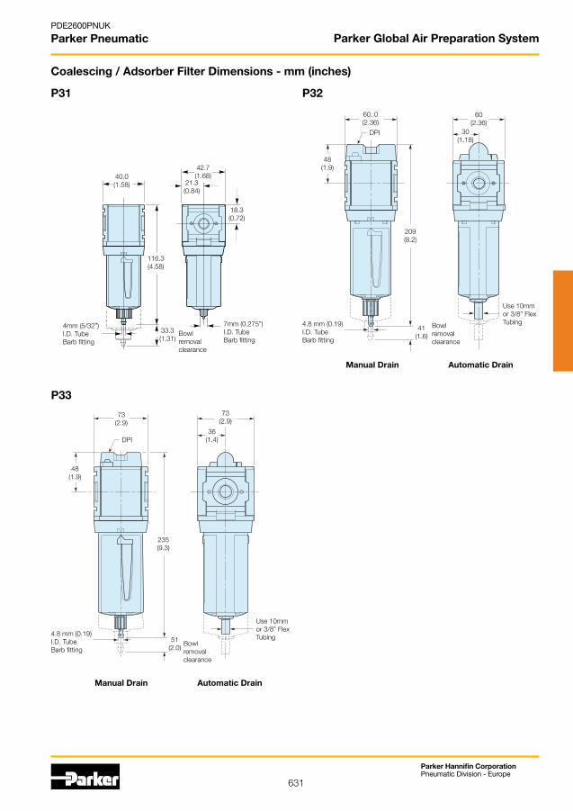
631
Parker Hannifin CorporationPneumatic Division - Europe
PDE2600PNUK
Parker Pneumatic
40.0(1.58)
42.7(1.68)
18.3(0.72)
116.3(4.58)
33.3(1.31)
21.3(0.84)
Bowl removal clearance
4mm (5/32”)I.D. TubeBarb fitting
7mm (0.275”)I.D. TubeBarb fitting
60,.0(2.36)
30(1.18)
41(1.6)
60(2.36)
Bowl removal clearance
DPI
4.8 mm (0.19)I.D. TubeBarb fitting
Use 10mm or 3/8” Flex Tubing
48(1.9)
209(8.2)
73(2.9)
36(1.4)
235(9.3)
51(2.0)
73(2.9)
4.8 mm (0.19)I.D. TubeBarb fitting
Bowl removal clearance
DPI
Use 10mm or 3/8” Flex Tubing
48(1.9)
Coalescing / Adsorber Filter Dimensions - mm (inches)
P31 P32
P33
Parker Global Air Preparation System
Manual Drain Automatic Drain
Manual Drain Automatic Drain

632
Parker Hannifin CorporationPneumatic Division - Europe
PDE2600PNUK
Parker Pneumatic
Regulator Dimensions - mm (inches)
P31 P32
P33
NOTE: Ø 30 mm hole required for panel nut mounting.
40(1.58)
64(2.53)
37(1.46)
61(2.4)
100.1(3.94)
34.1(1.34)
NOTE: Ø 47 mm hole required for panel nut mounting.
60(2.36)
30(1.2)
65(2.57)
60(2.36)
94(3.74)
136(5.4)
78.7(3.1)
93(3.66)
NOTE: Ø 60 mm hole required for panel nut mounting.
73(2.9)
83.8(3.3)
108(4.27)
72(2.83)
149(5.9)
105(4.16)
37(1.44)
73(2.9)
Parker Global Air Preparation System

633
Parker Hannifin CorporationPneumatic Division - Europe
PDE2600PNUK
Parker Pneumatic
Filter Regulator Dimensions - mm (inches)
P31 P32
P33
Note:Flush-mounted gauge kits will not fit units originally purchased with threaded gauge ports.
40(1.58)
164.1(6.46)
33.3(1.31)
Bowl removal clearance
7mm (0.275”)I.D. Tube fitting
66(2.6)
37(1.46)
64(2.53)
4mm (5/32”)I.D. Tube fitting
93(3.66)
60(2.36)
30(1.2)
248(9.76)
41(1.6)
65(2.57)
Bowl removal clearance
4.8 (0.19)I.D. TubeBarb fitting
60(2.36)
95(3.74)
Use 10mm or 3/8” Flex Tubing
Manual Drain Automatic Drain
104(4.1)
73(2.9)
37(1.44)
291(11.44)
51(2.0) 72
(2.83)
Bowl removal clearance
4.8 (0.19)I.D. TubeBarb fitting
73(2.9)
108(4.27)
Use 10mm or 3/8” Flex Tubing
Manual Drain Automatic Drain
Parker Global Air Preparation System

634
Parker Hannifin CorporationPneumatic Division - Europe
PDE2600PNUK
Parker Pneumatic
Lubricator Dimensions - mm (inches)
P31 P32
P33
57.2(2.25)
21.3(0.84)
40(1.58)
147.5(5.8)
12.7(0.5)
Bowl removal clearance
42.7(1.68)
30(1.18)
60(2.36)
211(8.3)
41(1.6)
Bowl removal clearance
60(2.36)
57.6(2.27)
36(1.44)
73(2.9)
237.6(9.35)
51(2.0)
Bowl removal clearance
73(2.9)
57.6(2.27)
Parker Global Air Preparation System

635
Parker Hannifin CorporationPneumatic Division - Europe
PDE2600PNUK
Parker Pneumatic Parker Global Air Preparation System
Port Description Order code
1/4 Solenoid operated (not included) P31TA12SGN0000
1/4 24VDC Solenoid & cable plug P31TA12SGNC2CN
1/4 Air pilot operated P31TA12PPN
1/2 Solenoid operated (not included) P32TA14SCN0000
1/2 24VDC 30mm coil & cable plug incl. P32TA14SCNA2CN
1/2 Air pilot operated P32TA14PPN
Combined Soft Start Dump Valve andRemote Operated Dump Valve
Port Description Order code
1/4 Solenoid operated (not included) P31DA12SGN0000
1/4 24VDC Solenoid & cable plug P31DA12SGNC2CN
1/4 Air pilot operated P31DA12PPN
1/2 Solenoid operated (not included) P32DA14SCN0000
1/2 24VDC 30mm coil & cable plug incl. P32DA14SCNA2CN
1/2 Air pilot operated P32DA14PPN
Remote Operated Dump Valve
Port Description Order code
1/4 Solenoid operated (not included) P31SA12SGN0000
1/4 24VDC Solenoid & cable plug P31SA12SGNC2CN
1/4 External air pilot (1/8 threaded) P31SA12PPN
1/2 Solenoid operated (not included) P32SA14SCN0000
1/2 24VDC 30mm coil & cable plug P32SA14SCNA2CN
1/2 Internal air pilot operated P32SA14Y0N
1/2 External air pilot (1/8 threaded) P32SA14PPN
Soft Start Valve
Safety Lockout Valves
Model Type Port Size Thread type Safety Lockout Valve Flow from left to right
P31 1/4 BSPP P31VA12LSAN
P32 3/8 BSPP P32VA13LSAN
1/2 BSPP P32VA14LSAN
P33 1/2 BSPP P33VA14LSAN
3/4 BSPP P33VA16LSAN
For thread type: NPT 9
Model Type Port Size Thread type Safety Lockout Valve Flow from right to left
P32 3/8 BSPP P32VA13LSBN
1/2 BSPP P32VA14LSBN
P33 1/2 BSPP P33VA14LSBN
3/4 BSPP P33VA16LSBN
Manifold Blocks
For thread type: BSPP 1
NPT 9
Model typePort size
Thread type
Flowdm3/s (scfm)
Modular Ball ValveFlow from left to right
P31 1/4" BSPP 20 (42.4) P31VA12LBNN
P32 3/8" BSPP 90 (190.7) P32VA13LBNN
1/2" BSPP 122 (258.5) P32VA14LBNN
P33 1/2" BSPP 122 (258.5) P33VA14LBNN
3/4" BSPP 122 (258.5) P33VA16LBNN
Modular Ball Valve
Model In/Out Auxiliary Auxilliary Thread Order CodeType Port Port Port Type Size Size Size Top Bottom
P31 1/4” 1/4” 1/4” BSPP P31MA12022N
P32 1/2” 1/4” 1/2” BSPP P32MA14024N
P33 3/4” 1/4” 1/2” BSPP P33MA16024N
For thread type: BSPP 1 NPT 9
T-Bracket w / Body ConnectorP31 P32 P33
P31KA00MT P32KA00MT P32KA00MT
C-Bracket(Fits to filter and lubricator body)
P31
P31KA00MW
Body ConnectorP31 P32 P33
P31KA00CB P32KA00CB P32KA00CB
Body Connector ‘O’ ring kit - Pack of 5
P31 P32
P31KA00CY P32KA00CY
Angle Bracket(Fits to regulator and filter/regulator)
P31 P32 P33
P31KA00MR P32KA00MR P32KA00MR
T-Bracket(Fits to body connector or port block)
P32 P33
P32KA00MB P32KA00MB
L-Bracket(Fits to filter and lubricator body)
P32 P33
P32KA00ML P33KA00ML
Panel mounting nut(Aluminium)
P31 P32 P33
P31KA00MM P32KA00MM P33KA00MM
Branch ManifoldP32 1/2” 1/4” 1/4” BSPP P32MD14022N
P32 1/4” 1/4” 1/4” BSPP P32MD12022NSeal kit for square gauge mtg on P32MD P32KA00RX

636
Parker Hannifin CorporationPneumatic Division - Europe
PDE2600PNUK
Parker Pneumatic
Accessories Kits
Series Description Order Code
P31 P31KA00MPP32 Panel Mount Nut (Plastic) P32KA00MPP33 P33KA00MP
P31 P31KA00MMP32 Panel Mount Nut (Aluminium) P32KA00MMP33 P33KA00MM
P31 P31KA00ESEP32 5µ Element Kit P32KA00ESEP33 P33KA00ESE
P31 P31KA00ESGP32 40µ Element Kit P32KA00ESGP33 P33KA00ESG
P31 P31KA00ES9P32 1µ Element Kit P32KA00ES9P33 P33KA00ES9
P31 P31KA00ESCP32 0.01µ Element Kit P32KA00ESCP33 P33KA00ESC
P31 P31KA00ESAP32 Adsorber Element Kit P32KA00ESAP33 P33KA00ESA
P32 / P33 Auto Drain Kit P32KA00DA
P32 / P33 Differential Pressure Indicator Kit P32KA00RQ
Fill Plug Kit
P31 / P32 / P33 Drip Control Assembly Kit P32KA00PG
P31 P31KA00PLP32 / P33 P32KA00PL
Parker Global Air Preparation System
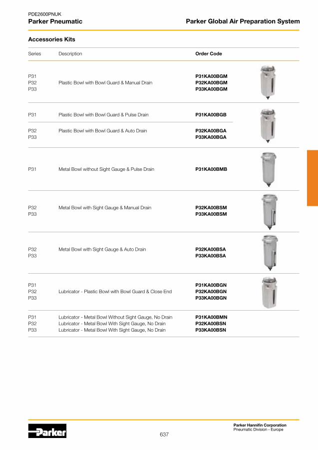
637
Parker Hannifin CorporationPneumatic Division - Europe
PDE2600PNUK
Parker Pneumatic
Series Description Order Code
Accessories Kits
P31 P31KA00BGMP32 Plastic Bowl with Bowl Guard & Manual Drain P32KA00BGMP33 P33KA00BGM
P31 Plastic Bowl with Bowl Guard & Pulse Drain P31KA00BGB
P32 Plastic Bowl with Bowl Guard & Auto Drain P32KA00BGAP33 P33KA00BGA
P31 Metal Bowl without Sight Gauge & Pulse Drain P31KA00BMB
P32 Metal Bowl with Sight Gauge & Manual Drain P32KA00BSMP33 P33KA00BSM
P32 Metal Bowl with Sight Gauge & Auto Drain P32KA00BSAP33 P33KA00BSA
P31 P31KA00BGNP32 Lubricator - Plastic Bowl with Bowl Guard & Close End P32KA00BGNP33 P33KA00BGN
P31 Lubricator - Metal Bowl Without Sight Gauge, No Drain P31KA00BMNP32 Lubricator - Metal Bowl With Sight Gauge, No Drain P32KA00BSNP33 Lubricator - Metal Bowl With Sight Gauge, No Drain P33KA00BSN
Parker Global Air Preparation System
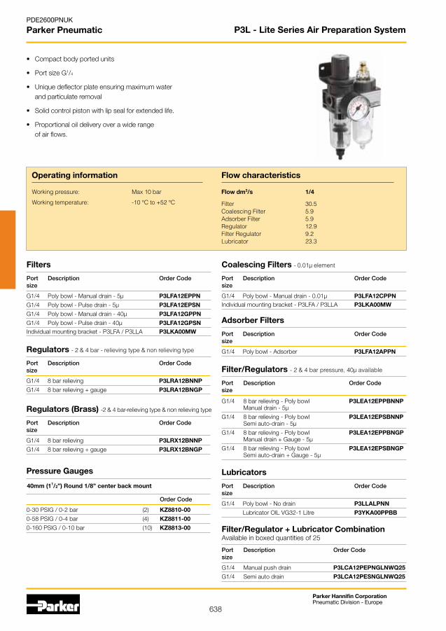
638
Parker Hannifin CorporationPneumatic Division - Europe
PDE2600PNUK
Parker Pneumatic
• Compactbodyportedunits
• PortsizeG1/4
• Uniquedeflectorplateensuringmaximumwater and particulate removal
• Solidcontrolpistonwithlipsealforextendedlife.
• Proportionaloildeliveryoverawiderange of air flows.
Filters
Port Description Order Codesize
G1/4 Poly bowl - Manual drain - 5µ P3LFA12EPPN
G1/4 Poly bowl - Pulse drain - 5µ P3LFA12EPSN
G1/4 Poly bowl - Manual drain - 40µ P3LFA12GPPN
G1/4 Poly bowl - Pulse drain - 40µ P3LFA12GPSNIndividual mounting bracket - P3LFA / P3LLA P3LKA00MW
Operating information
Working pressure: Max 10 bar
Working temperature: -10 °C to +52 °C
Flow characteristics
Flow dm3/s 1/4
Filter 30.5Coalescing Filter 5.9Adsorber Filter 5.9Regulator 12.9Filter Regulator 9.2Lubricator 23.3
Pressure Gauges
Order Code
0-30 PSIG / 0-2 bar (2) KZ8810-00
0-58 PSIG / 0-4 bar (4) KZ8811-00
0-160 PSIG / 0-10 bar (10) KZ8813-00
P3L - Lite Series Air Preparation System
Coalescing Filters - 0.01µ element
Port Description Order Codesize
G1/4 Poly bowl - Manual drain - 0.01µ P3LFA12CPPNIndividual mounting bracket - P3LFA / P3LLA P3LKA00MW
Adsorber Filters
Port Description Order Codesize
G1/4 Poly bowl - Adsorber P3LFA12APPNRegulators - 2 & 4 bar - relieving type & non relieving type
Port Description Order Codesize
G1/4 8 bar relieving P3LRA12BNNP
G1/4 8 bar relieving + gauge P3LRA12BNGP
Regulators (Brass) -2 & 4 bar-relieving type & non relieving type
Port Description Order Codesize
G1/4 8 bar relieving P3LRX12BNNP
G1/4 8 bar relieving + gauge P3LRX12BNGP
Filter/Regulators - 2 & 4 bar pressure, 40µ available
Port Description Order Codesize
G1/4 8 bar relieving - Poly bowl P3LEA12EPPBNNP Manual drain - 5µ
G1/4 8 bar relieving - Poly bowl P3LEA12EPSBNNP Semi auto-drain - 5µ
G1/4 8 bar relieving - Poly bowl P3LEA12EPPBNGP Manual drain + Gauge - 5µ
G1/4 8 bar relieving - Poly bowl P3LEA12EPSBNGP Semi auto-drain + Gauge - 5µ
Lubricators
Port Description Order Codesize
G1/4 Poly bowl - No drain P3LLALPNN
LubricatorOILVG32-1Litre P3YKA00PPBB
40mm (11/2”) Round 1/8” center back mount
Filter/Regulator + Lubricator CombinationAvailable in boxed quantities of 25
Port Description Order Codesize
G1/4 Manual push drain P3LCA12PEPNGLNWQ25
G1/4 Semi auto drain P3LCA12PESNGLNWQ25
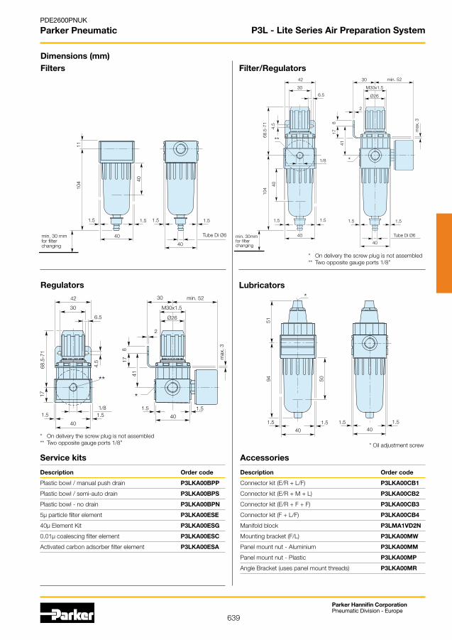
639
Parker Hannifin CorporationPneumatic Division - Europe
PDE2600PNUK
Parker Pneumatic
Description Order code
Plastic bowl / manual push drain P3LKA00BPP
Plastic bowl / semi-auto drain P3LKA00BPS
Plastic bowl - no drain P3LKA00BPN
5µ particle filter element P3LKA00ESE
40µ Element Kit P3LKA00ESG
0.01µ coalescing filter element P3LKA00ESC
Activated carbon adsorber filter element P3LKA00ESA
Dimensions (mm)Filters
Regulators
Filter/Regulators
Service kits
Lubricators
P3L - Lite Series Air Preparation System
Accessories
Description Order code
Connector kit (E/R + L/F) P3LKA00CB1
Connector kit (E/R + M + L) P3LKA00CB2
Connector kit (E/R + F + F) P3LKA00CB3
Connector kit (F + L/F) P3LKA00CB4
Manifold block P3LMA1VD2N
Mounting bracket (F/L) P3LKA00MW
Panel mount nut - Aluminium P3LKA00MM
Panel mount nut - Plastic P3LKA00MP
Angle Bracket (uses panel mount threads) P3LKA00MR
40
1.5
104
11
40
1.5
min. 30 mmfor filterchanging
1.5 1.5
40
Tube Di Ø6 40
1.5
42
30
6.5
30 min. 52
M30x1.5
Ø26
2
1.5 1.5
40
Tube Di Ø6
*
178
41
104
4.5
**
40
68.5
-71
1.5
max
. 3
min. 30mmfor filterchanging
1/8
40
1.5 1.5 1.540
*
9451
50
1.5
42
30
6.5
30 min. 52
M30x1.5
Ø26
2
178
41
17
4.5
68.5
-71
max
. 3
40
1.51.5 1.5
40
1/81.5
**
*
* Ondeliverythescrewplugisnotassembled** Two opposite gauge ports 1/8”
* Ondeliverythescrewplugisnotassembled** Two opposite gauge ports 1/8”
*Oiladjustmentscrew

640
Parker Hannifin CorporationPneumatic Division - Europe
PDE2600PNUK
Parker Pneumatic P3X - Lite Air Preparation System
Nano MistThere are innovations that bring selective improvements. And then there are real innovations. Innovations that set new standards. Like the new Parker Moduflex Lite series.
Simple. Convincing in the Details
New Nano Mist Technology,
New Lubricator Concept.
Self-Adjusting.
This ensures that there is neither too little nor too much oil in the system, which leads to clear economic and ecological advantages. In addition, with conventional systems, the distance between the lubricator and the equipment has to be less than 8 meters. With larger distances, the dispensed oil is deposited as a wall flow. The new lubricator principle of the Moduflex Lite allows for distances of up to 40 meters. This opens up new scope for the design of even more efficient production systems.
With conventional lubricators, only the oil volume per time unit can be adjusted. If the demand changes, the quantity dispensed still remains constant.
The Moduflex Lite lubricator concept sets new benchmarks here. For the first time, the oil volume is automatically adjusted to the flow rate.

641
Parker Hannifin CorporationPneumatic Division - Europe
PDE2600PNUK
Parker Pneumatic P3X - Lite Air Preparation System
Popular Combinations
Options:
P 3 X G E
Filter/Reg + Lubricator CA
Slide valve + Filter/Reg AN
Slide valve + Filter/Reg AA + Lubricator
CombinedManual/SemiAuto Drain
Auto Drain
C
A
0 - 8 bar with gauge
0 - 16 bar with gauge
G
J
BSPP (G) 1
NPT * 9
Slide Valve + Filter/Regulator + Lubricator Combinations (50mg/m3)5 micron element, 8 bar Regulator + Gauge and Wall Mounting Brackets
Port size Combined Manual/Semi-Auto Drain Flow dm3/s Weight (g) Auto Drain Flow dm3/s Weight (g)
G1/2 P3XAA14GECNGPNW 76 1300 P3XAA14GEANGPNW 76 1300
G3/4 P3XAA16GECNGPNW 77 1300 P3XAA16GEANGPNW 77 1300
Slide Valve + Filter/Regulator Combinations5 micron element, 8 bar Regulator + Gauge and Wall Mounting Brackets
Filter/Regulator + Lubricator Combinations (50mg/m3)5 micron element, 8 bar Regulator + Gauge and Wall Mounting Brackets
Port size Combined Manual/Semi-Auto Drain Flow dm3/s Weight (g) Auto Drain Flow dm3/s Weight (g)
G1/2 P3XAN14GECNGW 105 950 P3XAN14GEANGW 105 950
G3/4 P3XAN16GECNGW 106 950 P3XAN16GEANGW 106 950
Port size Combined Manual/Semi-Auto Drain Flow dm3/s Weight (g) Auto Drain Flow dm3/s Weight (g)
G1/2 P3XCA14GECNGPNW 76 1000 P3XCA14GEANGPNW 76 1000
G3/4 P3XCA16GECNGPNW 77 1000 P3XCA16GEANGPNW 77 1000
W
Add only for options with lubricator
1/2 4
3/4 6
* NPT ports on request 1/2” size only
Non rise - Standard
Tamperproof - Lockable
N
A
(50mg/m3) PN
(5mg/m3) SN

642
Parker Hannifin CorporationPneumatic Division - Europe
PDE2600PNUK
Parker Pneumatic
• Integral 1/2 or 3/4 ports
• Highefficiency5micronelementasstandard
• Excellent water removal efficiency
• Secondary pressure ranges 4, 8 and 16 bar
• Rolling diaphragm for extended life
• Secondary aspiration plus balanced poppet provides quick response and accurate pressure regulation.
• Lowtemperature-40’CwithRegulators/Filtersand Filter Regulators using combined manual/semi auto drain as standard without pressure gauge.
Filters - 5 micron element
Port Description Order Codesize
G1/2 Manual drain/Semi auto P3XFA14EGCN
G1/2 Auto drain P3XFA14EGAN
G3/4 Manual drain / Semi auto P3XFA16EGCN
G3/4 Auto drain P3XFA16EGAN
Regulators - 4 & 8 bar - non relieving options available
Port Description Order Code
size
G1/2 8 bar relieving P3XRA14BNNN
G1/2 8 bar relieving + gauge P3XRA14BNGN
G3/4 8 bar relieving P3XRA16BNNN
G3/4 8 bar relieving + gauge P3XRA16BNGN
G1/2 8 bar relieving, tamperproof P3XRA14BANN
G1/2 8 bar relieving, tamperproof + gauge P3XRA14BAGN
G3/4 8 bar relieving, tamperproof P3XRA16BANN
G3/4 8 bar relieving, tamperproof + gauge P3XRA16BAGN
Coalescing Filters - 0.01 micron element
Filter/Regulators4 and 16 bar, non relieving options available
Lubricators
Port Description Order Codesize
G1/2 Oilmist,fillunderpressure(50mg/m3) P3XLA14PGNN
G3/4 Oilmist,fillunderpressure(50mg/m3) P3XLA16PGNN
G1/2 Oilmist,fillunderpressure(5mg/m3) P3XLA14SGNN
G3/4 Oilmist,fillunderpressure(5mg/m3) P3XLA16SGNN
LubricatorOILVG15:ISO3448-100ml P3XKA00PPA
LubricatorOILVG32-1Litre P3YKA00PPBB
Operating information
Working pressure: Max 16 bar
Working temperature: -10 °C to +60 °C
Flow characteristics
Flow dm3/s 1/2 3/4
Filter 55 57Coalescing Filter 24 24Adsorber Filter 18 18Regulator 122 134Filter Regulator 111 113Lubricator 78 78
Mounting bracket P3XKA00MW
Port Description Order Codesize
G1/2 Coalescing 0.01µm, manual/semi auto drain P3XFA14DGCN
G1/2 Coalescing Filter 0.01µm, auto drain P3XFA14DGAN
G3/4 Coalescing 0.01µm, manual/semi auto drain P3XFA16DGCN
G3/4 Coalescing Filter 0.01µm, auto drain P3XFA16DGAN
Pressure Gauges
Order Code
0 - 10 bar KG8012-00
0 - 16 bar KG8013-00
Port Description Order Codesize
G1/2 8 bar, relieving manual/semi auto drain P3XEA14EGCBNNN
G1/2 8 bar, relieving auto drain P3XEA14EGABNNN
G1/2 8 bar, relieving manual/semi auto + gauge P3XEA14EGCBNGN
G1/2 8 bar, relieving auto drain + gauge P3XEA14EGABNGN
G3/4 8 bar, relieving manual/semi auto drain P3XEA16EGCBNNN
G3/4 8 bar, relieving auto drain P3XEA16EGABNNN
G3/4 8 bar, relieving manual/semi auto + gauge P3XEA16EGCBNGN
G3/4 8 bar, relieving auto drain + gauge P3XEA16EGABNGN
P3X - Lite Air Preparation System
Adsorber FiltersPort Description Order Codesize
G1/2 Adsorber, manual/semi auto drain P3XFA14AGCN
G3/4 Adsorber, manual/semi auto drain P3XFA16AGCN
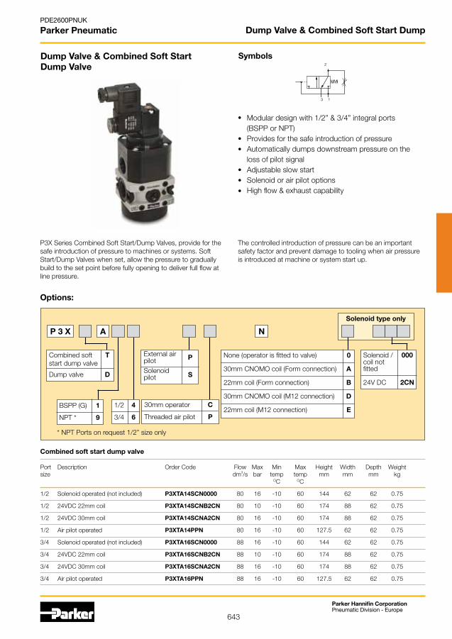
643
Parker Hannifin CorporationPneumatic Division - Europe
PDE2600PNUK
Parker Pneumatic
Dump Valve & Combined Soft Start Dump Valve
Symbols
Modular design with 1/2” & 3/4” integral ports(BSPP or NPT)Provides for the safe introduction of pressureAutomatically dumps downstream pressure on theloss of pilot signalAdjustableslowstartSolenoid or air pilot optionsHighflow&exhaustcapability
2
3 1
Port Description OrderCode Flow Max Min Max Height Width Depth Weightsize dm3/s bar temp temp mm mm mm kg OC OC
1/2 Solenoid operated (not included) P3XTA14SCN0000 80 16 -10 60 144 62 62 0.75
1/2 24VDC 22mm coil P3XTA14SCNB2CN 80 10 -10 60 174 88 62 0.75
1/2 24VDC 30mm coil P3XTA14SCNA2CN 80 16 -10 60 174 88 62 0.75
1/2 Air pilot operated P3XTA14PPN 80 16 -10 60 127.5 62 62 0.75
3/4 Solenoid operated (not included) P3XTA16SCN0000 88 16 -10 60 144 62 62 0.75
3/4 24VDC 22mm coil P3XTA16SCNB2CN 88 10 -10 60 174 88 62 0.75
3/4 24VDC 30mm coil P3XTA16SCNA2CN 88 16 -10 60 174 88 62 0.75
3/4 Air pilot operated P3XTA16PPN 88 16 -10 60 127.5 62 62 0.75
Combined soft start dump valve
P3X Series Combined Soft Start/Dump Valves, provide for the safe introduction of pressure to machines or systems. Soft Start/Dump Valves when set, allow the pressure to gradually build to the set point before fully opening to deliver full flow at line pressure.
The controlled introduction of pressure can be an important safety factor and prevent damage to tooling when air pressure is introduced at machine or system start up.
Options:
P 3 X
External airpilotSolenoid pilot
P
S
None (operator is fitted to valve) 0
30mmCNOMOcoil(Formconnection) A
22mm coil (Form connection) B
30mmCNOMOcoil(M12connection) D
22mm coil (M12 connection) E
N
Solenoid / 000coil not fitted
24V DC 2CN
BSPP (G) 1
NPT * 9
Solenoid type only
1/2 4
3/4 6
30mm operator C
Threaded air pilot P
* NPT Ports on request 1/2” size only
Combined soft T start dump valve Dump valve D
A
Dump Valve & Combined Soft Start Dump

644
Parker Hannifin CorporationPneumatic Division - Europe
PDE2600PNUK
Parker Pneumatic
Dimensions (mm)
1: Inlet port G1/2 (G3/4)2: Outlet port G1/2 (G/3)3: Exhaust port G1/24: Gauge port G1/4
1: Inlet port G1/2 (G3/4)2: Outlet port G1/2 (G/3)3: Exhaust port G1/24: Gauge port G1/412: Pilot port G1/8
Dump Valve & Combined Soft Start Dump
L S NP 3 X V A
BSPP (G) 1
NPT * 9
G1/2 4
G3/4 6
* NPT ports on request (1/2” size only)
41
73O
3335
61,545
9
8,5
Description Order code Order code Weight (g) BSPP NPT
G1/2” P3XMA1V0N P3XMA9V0N 170
G3/4” P3XMA160N 170
G1/
2
G1/
2
G1/4G1/2
SW30
G1/4
62 62
4622
9
Modular Slide Valve Modular Manifold
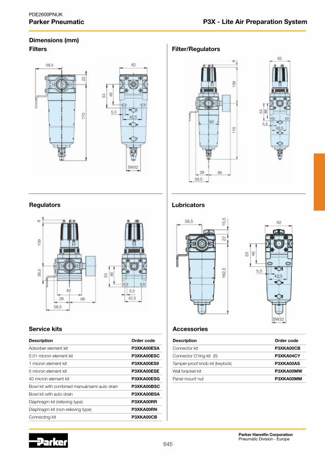
645
Parker Hannifin CorporationPneumatic Division - Europe
PDE2600PNUK
Parker Pneumatic
Description Order code
Connector kit P3XKA00CB
ConnectorO’ringkit(5) P3XKA04CY
Tamper-proof knob kit (keylock) P3XKA00AS
Wall bracket kit P3XKA00MW
Panel mount nut P3XKA00MM
Description Order code
Adsorber element kit P3XKA00ESA
0.01 micron element kit P3XKA00ESC
1 micron element kit P3XKA00ES9
5 micron element kit P3XKA00ESE
40 micron element kit P3XKA00ESG
Bowl kit with combined manual/semi auto drain P3XKA00BSC
Bowl kit with auto drain P3XKA00BSA
Diaphragm kit (relieving type) P3XKA00RR
Diaphragm kit (non-relieving type) P3XKA00RN
Connecting kit P3XKA00CB
Dimensions (mm)Filters
Regulators
Filter/Regulators
Service kits
Lubricators
P3X - Lite Air Preparation System
62
39
42,55,5
53 46
170
109
58,5
8
66
62
62
SW32
42,55,5
53 46
170
22
58,5
62
66 42,5
5,5
109
4636,5
8
58,5
53
39
62
SW32
42,55,5
53 46
162,
522
58,510
,5
Accessories
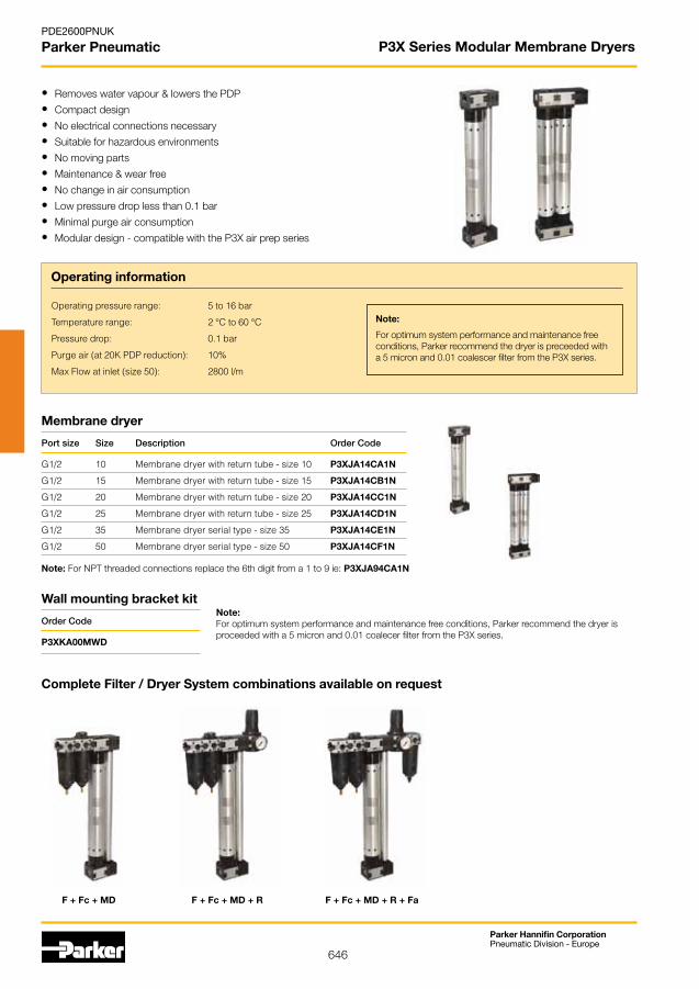
646
Parker Hannifin CorporationPneumatic Division - Europe
PDE2600PNUK
Parker Pneumatic P3X Series Modular Membrane Dryers
• Removes water vapour & lowers the PDP
• Compact design
• No electrical connections necessary
• Suitable for hazardous environments
• No moving parts
• Maintenance & wear free
• No change in air consumption
• Low pressure drop less than 0.1 bar
• Minimal purge air consumption
• Modular design - compatible with the P3X air prep series
Membrane dryer
Operating information
Operating pressure range: 5 to 16 bar
Temperature range: 2 °C to 60 °C
Pressure drop: 0.1 bar
Purge air (at 20K PDP reduction): 10%
Max Flow at inlet (size 50): 2800 l/m
Note:
For optimum system performance and maintenance free conditions, Parker recommend the dryer is preceeded with a 5 micron and 0.01 coalescer filter from the P3X series.
Port size Size Description Order Code
G1/2 10 Membrane dryer with return tube - size 10 P3XJA14CA1N
G1/2 15 Membrane dryer with return tube - size 15 P3XJA14CB1N
G1/2 20 Membrane dryer with return tube - size 20 P3XJA14CC1N
G1/2 25 Membrane dryer with return tube - size 25 P3XJA14CD1N
G1/2 35 Membrane dryer serial type - size 35 P3XJA14CE1N
G1/2 50 Membrane dryer serial type - size 50 P3XJA14CF1N
Wall mounting bracket kit
Order Code
P3XKA00MWD
Note: For NPT threaded connections replace the 6th digit from a 1 to 9 ie: P3XJA94CA1N
Complete Filter / Dryer System combinations available on request
F + Fc + MD F + Fc + MD + R F + Fc + MD + R + Fa
Note:For optimum system performance and maintenance free conditions, Parker recommend the dryer is proceeded with a 5 micron and 0.01 coalecer filter from the P3X series.
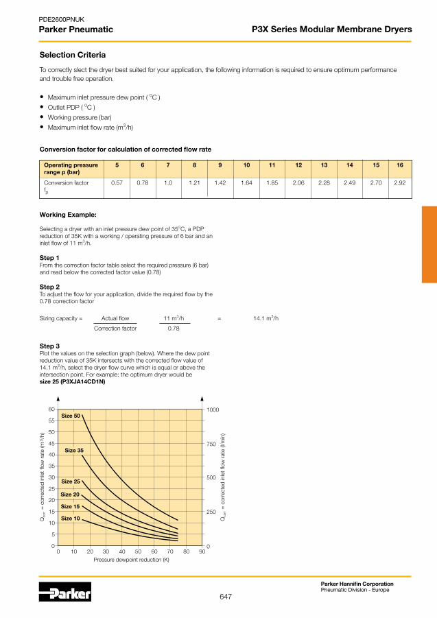
647
Parker Hannifin CorporationPneumatic Division - Europe
PDE2600PNUK
Parker Pneumatic P3X Series Modular Membrane Dryers
• Maximum inlet pressure dew point ( OC )
• OutletPDP(OC )
• Working pressure (bar)
• Maximum inlet flow rate (m3/h)
Selection Criteria
To correctly slect the dryer best suited for your application, the following information is required to ensure optimum performance and trouble free operation.
Operating pressure 5 6 7 8 9 10 11 12 13 14 15 16 range p (bar)
Conversion factor 0.57 0.78 1.0 1.21 1.42 1.64 1.85 2.06 2.28 2.49 2.70 2.92 fp
Conversion factor for calculation of corrected flow rate
Working Example:
Selecting a dryer with an inlet pressure dew point of 35OC, a PDPreduction of 35K with a working / operating pressure of 6 bar and aninlet flow of 11 m3/h.
Step 1From the correction factor table select the required pressure (6 bar)and read below the corrected factor value (0.78)
Step 2Toadjusttheflowforyourapplication,dividetherequiredflowbythe0.78 correction factor
Sizing capacity = Actual flow 11 m3/h = 14.1 m3/h
Correction factor 0.78
Step 3Plot the values on the selection graph (below). Where the dew pointreduction value of 35K intersects with the corrected flow value of14.1 m3/h, select the dryer flow curve which is equal or above theintersection point. For example: the optimum dryer would besize 25 (P3XJA14CD1N)

648
Parker Hannifin CorporationPneumatic Division - Europe
PDE2600PNUK
Parker Pneumatic
The P3Y system allows units to be connected together, without the use of pipe connectors, saving space; providing constant mounting centres; whilst maintaining a modern aesthetically pleasing appearance.
The P3Y Filters are specially designed to efficiently filter out rust, dirt, moisture and other impurities from compressed airlines.Operationisfullyautomaticwithaminimumofpressure drop. Coalescing filters and adsorber filters for high purity air are also included in the P3Y series.
The P3Y Regulators are designed to provide quick response and accurate pressure regulation for the most demanding hi-flow industrial applications.The rolling diaphragm was designed for long trouble-free operation and will not rupture or tear under high cycle or other demanding applications.
Regulator
Wall mounting bracket
Lubricator can be filled under pressure to eliminate downtime
40 micron filter element as standard
Wall mounting bracket
All units body ported
Neck mounting bracket
Neck mounting nut
Bodyconnectingkit
Flowdirectional arrows
Combined manual / semi-auto drain &auto drain options
Metal bowl with chemical resistant sight glass
Non rising control knob
Constant density lubrication
Nitrile ‘O’ ring seal
P3Y Air Preparation System
For the most demanding hi-flow industrial applications
The P3Y Modular FRL System
Standard Filter Coalescing Filter
Adsorber Filter Dust Filter
Selection of Filters
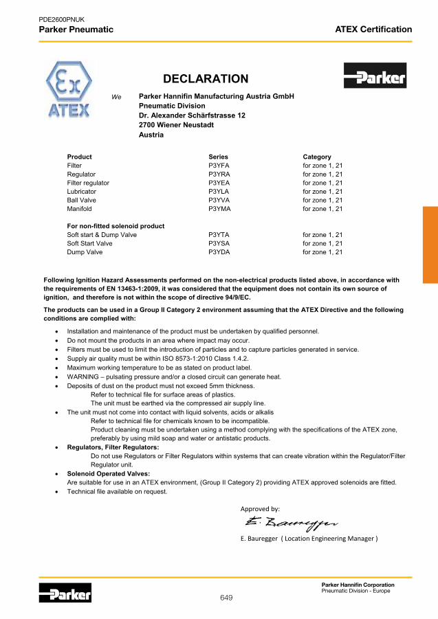
649
Parker Hannifin CorporationPneumatic Division - Europe
PDE2600PNUK
Parker Pneumatic
DECLARATION
Parker Hannifin Manufacturing Austria GmbH Pneumatic Division Dr. Alexander Schärfstrasse 12 2700 Wiener Neustadt Austria
We
Product Series Category Filter P3YFA for zone 1, 21 Regulator P3YRA for zone 1, 21 Filter regulator P3YEA for zone 1, 21 Lubricator P3YLA for zone 1, 21 Ball Valve P3YVA for zone 1, 21 Manifold P3YMA for zone 1, 21 For non-fitted solenoid product Soft start & Dump Valve P3YTA for zone 1, 21 Soft Start Valve P3YSA for zone 1, 21 Dump Valve P3YDA for zone 1, 21
Following Ignition Hazard Assessments performed on the non-electrical products listed above, in accordance with the requirements of EN 13463-1:2009, it was considered that the equipment does not contain its own source of ignition, and therefore is not within the scope of directive 94/9/EC. The products can be used in a Group II Category 2 environment assuming that the ATEX Directive and the following conditions are complied with:
Installation and maintenance of the product must be undertaken by qualified personnel. Do not mount the products in an area where impact may occur. Filters must be used to limit the introduction of particles and to capture particles generated in service. Supply air quality must be within ISO 8573-1:2010 Class 1.4.2. Maximum working temperature to be as stated on product label. WARNING – pulsating pressure and/or a closed circuit can generate heat. Deposits of dust on the product must not exceed 5mm thickness.
Refer to technical file for surface areas of plastics. The unit must be earthed via the compressed air supply line.
The unit must not come into contact with liquid solvents, acids or alkalis Refer to technical file for chemicals known to be incompatible. Product cleaning must be undertaken using a method complying with the specifications of the ATEX zone, preferably by using mild soap and water or antistatic products.
Regulators, Filter Regulators: Do not use Regulators or Filter Regulators within systems that can create vibration within the Regulator/Filter Regulator unit.
Solenoid Operated Valves: Are suitable for use in an ATEX environment, (Group II Category 2) providing ATEX approved solenoids are fitted.
Technical file available on request.
Approved by:
E. Bauregger ( Location Engineering Manager )
ATEX Certification

650
Parker Hannifin CorporationPneumatic Division - Europe
PDE2600PNUK
Parker Pneumatic P3Y Air Preparation System
• Integral 3/4 or 1” ports (BSPP or NPT)
• Highefficiencyelementasstandard
• Excellent water removal efficiency
• Robust but lightweight aluminium construction
• Secondary pressure ranges 12 and 16 bar
• Rolling diaphragm for extended life
• Secondary aspiration plus balanced poppet provides quick response and accurate pressure regulation.
• Lowtemperature-40’CwithRegulators/FiltersandFilter Regulators using combined manual/semi auto drain as standard without pressure gauge.
Filters - 40 micron element
Port Description Order Codesize
G3/4 Manual drain/Semi auto P3YFA16GSCN
G3/4 Auto drain P3YFA16GSAN
G1” Manual drain / Semi auto P3YFA18GSCN
G1” Auto drain P3YFA18GSAN
Regulators - relieving type - non relieving options available
Port Description Order Code
size
G3/4 12 bar relieving P3YRA16BNEN
G3/4 12 bar relieving + gauge P3YRA16BNFN
G1” 12 bar relieving P3YRA18BNEN
G1” 12 bar relieving + gauge P3YRA18BNFN
G3/4 12 bar relieving, lockable P3YRA16BAEN
G3/4 12 bar relieving, lockable + gauge P3YRA16BAFN
G1” 12 bar relieving, lockable P3YRA18BAEN
G1” 12 bar relieving, lockable + gauge P3YRA18BAFN
Coalescing Filters - 0.01 micron element
Filter/Regulators - relieving type - non relieving options available
Lubricators
Port Description Order Codesize
G3/4 Oilmist,fillunderpressure P3YLA16LSNN
G1” Oilmist,fillunderpressure P3YLA18LSNN
Operating informationWorking pressure: Max 17.5 bar
Working temperature: -10 °C to +60 °C
Flow characteristicsFlow dm3/s 3/4 1”
Filter 116 119Dust Filter 137 145Coalescing Filter 49 59Adsorber Filter 47 50Regulator 155 321Filter Regulator 190 237Lubricator 162 184
Mounting bracket P3YKA00CW
Port Description Order Codesize
G3/4 Coalescing 0.01µm, manual/semi auto drain P3YFA16DSCN
G3/4 Coalescing Filter 0.01µm, auto drain P3YFA16DSAN
G1” Coalescing 0.01µm, manual/semi auto drain P3YFA18DSCN
G1” Coalescing Filter 0.01µm, auto drain P3YFA18DSAN
Pressure Gauges
Order Code
0 - 10 bar KG8012-00
0 - 16 bar KG8013-00
Port Description Order Codesize
G3/4 12 bar, relieving manual/semi auto drain P3YEA16GSCBNEN
G3/4 12 bar, relieving auto drain P3YEA16GSABNEN
G3/4 12 bar, relieving manual/semi auto + gauge P3YEA16GSCBNFN
G3/4 12 bar, relieving auto drain + gauge P3YEA16GSABNFN
G1” 12 bar, relieving manual/semi auto drain P3YEA18GSCBNEN
G1” 12 bar, relieving auto drain P3YEA18GSABNEN
G1” 12 bar, relieving manual/semi auto + gauge P3YEA18GSCBNFN
G1” 12 bar, relieving auto drain + gauge P3YEA18GSABNFN
Adsorber FiltersPort Description Order Codesize
G3/4 Adsorber 0.01µm, manual drain P3YFA16ASCN
G1” Adsorber 0.01µm, manual drain P3YFA18ASCN
Dust Filters - 1 micron element
Port Description Order Codesize
G3/4 Manual drain/Semi auto P3YFA162SCN
G3/4 Auto drain P3YFA162SAN
G1” Manual drain / Semi auto P3YFA182SCN
G1” Auto drain P3YFA182SAN

651
Parker Hannifin CorporationPneumatic Division - Europe
PDE2600PNUK
Parker Pneumatic
Combined Soft Start Dump Valve andRemote Operated Dump Valve
Port Description Order Codesize
G3/4 Solenoid operated (not included) P3YTA16SCN0000
G3/4 24VDC 22mm coil P3YTA16SCNB2CN
G3/4 Air pilot operated P3YTA16PPN
G1” Solenoid operated (not included) P3YTA18SCN0000
G1” 24VDC 22mm coil P3YTA18SCNB2CN
G1” Air pilot operated P3YTA18PPN
Soft Start Valve
Port Description Order Codesize
G3/4 Soft start valve P3YSA16Y0N
G1” Soft start valve P3YSA18Y0N
Pilot Operated Regulator
Port Description Order Codesize
G3/4 Pilot operated regulator P3YRA16BPPN
G1” Pilot operated regulator P3YRA18BPPN
Modular Ball Valve
Port Description Order Codesize
G3/4 Modular Ball Valve P3YVA16LBN
G1” Modular Ball Valve P3YVA18LBN
Modular Manifold
Port Description Width Order Codesize
G3/4 Modular Manifold (80 mm) P3YMA1V0N
G1” Modular Manifold (80 mm) P3YMA9V0N
G3/4 Modular Manifold (35 mm) P3YMA16024N
Optional Port Block Kits
Port Description Order Codesize
G11/4” Port block kit - BSPP P3YKA1ACP
G11/2” Port block kit - BSPP P3YKA1BCP
G3/4” Port block kit - BSPP P3YKA16CP
G1” Port block kit - BSPP P3YKA18CP
P3Y Air Preparation System
Neck mounting bracket kit
Description Order Code
Neck mounting bracket kit P3YKA00MS
Connector kit
Description Order Code
Connector kit P3YKA00CB
Wall mounting brackets
Description Order Code
Wall mounting brackets P3YKA00CW

652
Parker Hannifin CorporationPneumatic Division - Europe
PDE2600PNUK
Parker Pneumatic P3Y Air Preparation System
Dimensions (mm)Filters
Regulators
Filter/Regulators
Service kits
Lubricators
Description Order code
5 micron element kit P3YKA00ESE
40 micron element kit P3YKA00ESG
Bowl kit with combined manual/semi auto drain P3YKA00BSC
Bowl kit with auto drain P3YKA00BSA
Key Lock Kit P3XKA00AS
Diaphragm kit (relieving type) P3YKA00RR
Diaphragm kit (non-relieving type) P3YKA00RN
Angle bracket + metal lock ring P3YKA00MS
Panel mount nut P3YKA00MM
Min. 80mm forfilter changing
* 1/4” gauge port
Min. 80mm forfilter changing * 1/4” gauge port

653
Parker Hannifin CorporationPneumatic Division - Europe
PDE2600PNUK
Parker Pneumatic ATEX Certification
DECLARATION
Parker Hannifin Manufacturing Austria GmbH Pneumatic Division Dr. Alexander Schärfstrasse 12 2700 Wiener Neustadt Austria
We
Product Series Category Filter P3ZFA for zone 1, 21 Regulator P3ZRA for zone 1, 21 Lubricator P3ZLA for zone 1, 21 Manifold P3ZMA for zone 1, 21 For non-fitted solenoid product Soft start & Dump Valve P3ZTA for zone 1, 21 Soft Start Valve P3ZSA for zone 1, 21 Dump Valve P3ZDA for zone 1, 21
Following Ignition Hazard Assessments performed on the non-electrical products listed above, in accordance with the requirements of EN 13463-1:2009, it was considered that the equipment does not contain its own source of ignition, and therefore is not within the scope of directive 94/9/EC. The products can be used in a Group II Category 2 environment assuming that the ATEX Directive and the following conditions are complied with:
Installation and maintenance of the product must be undertaken by qualified personnel. Do not mount the products in an area where impact may occur. Filters must be used to limit the introduction of particles and to capture particles generated in service. Supply air quality must be within ISO 8573-1:2010 Class 1.4.2. Maximum working temperature to be as stated on product label. WARNING – pulsating pressure and/or a closed circuit can generate heat. Deposits of dust on the product must not exceed 5mm thickness.
Refer to technical file for surface areas of plastics. The unit must be earthed via the compressed air supply line.
The unit must not come into contact with liquid solvents, acids or alkalis Refer to technical file for chemicals known to be incompatible. Product cleaning must be undertaken using a method complying with the specifications of the ATEX zone, preferably by using mild soap and water or antistatic products.
Regulators, Filter Regulators: Do not use Regulators or Filter Regulators within systems that can create vibration within the Regulator/Filter Regulator unit.
Solenoid Operated Valves: Are suitable for use in an ATEX environment, (Group II Category 2) providing ATEX approved solenoids are fitted.
Technical file available on request.
Approved by:
E. Bauregger ( Location Engineering Manager )

654
Parker Hannifin CorporationPneumatic Division - Europe
PDE2600PNUK
Parker Pneumatic
• Selfrelievingfeatureplusbalancedpoppetprovides quick response and accurate pressure regulation.
• ThreadedportflangeavailabletoG1-1/2”and G2”
• Proportionaloildeliveryoverawiderangeofair flows.
Filters
Port Description OrderCodesize
- 40µ auto drain without flange SAE P3ZFA00HMAN
G1.1/2” 40µ auto drain flange fitted to SAE P3ZFA1BHMAN
G2” 40µ auto drain flange fitted to SAE P3ZFA1CHMAN
Operating information
Working pressure: 0 - 17.5 bar
Working temperature: 0 °C to +60 °C
Flow characteristics
Flow Filter >666,6 dm3/s Regulator >666,6 dm3/s Lubricator >666,6 dm3/s
The all metal P3Z Series FRLs are ideal for most medium sized ring main installations.
P3Z Air Preparation System
Dust Filters
Port Description OrderCodesize
- 1µ auto drain (pressure relief) P3ZFA00MMAN without flange SAE
G1.1/2” 1µ auto drain (pressure relief) P3ZFA1BMMAN flange fitted to SAE
G2” 1µ auto drain (pressure relief) P3ZFA1CMMAN flange fitted to SAE
Coalescing Filters
Port Description OrderCodesize
- 0.01 micron, auto drain P3ZFA00DMAN
G1.1/2” 0.01 micron, auto drain, flange fitted to SAE P3ZFA1BDMAN
G2” 0.01 micron, auto drain, flange fitted to SAE P3ZFA1CDMAN
Adsorber Filters
Port Description OrderCodesize
- Adsorber, auto drain P3ZFA00BMAN
G1.1/2” Adsorber, auto drain P3ZFA1BBMAN
G2” Adsorber, auto drain P3ZFA1CBMAN
For more information see www.parker.com/euro_pneumatic

655
Parker Hannifin CorporationPneumatic Division - Europe
PDE2600PNUK
Parker Pneumatic
Options & Accessories
Port Description OrderCodesize
G1.1/2” Connection flange kit P3ZKA1BCP
G2” Connection flange kit P3ZKA1CCP
- Wall mounting kit P3ZKA00MW
- Coupling kit P3ZKA00CB
- Coupling‘O’ringkit(5off) P3ZKA0CCY
- Porting block kit (1”, 1/8” & 2 x 1/4” take off) P3ZMA1V0N
Regulators
Port Description OrderCodesize
- 8 bar, relieving + gauge, without flange SAE P3ZRA00BNGN
G1.1/2” 8 bar, relieving + gauge P3ZRA1BBNGN
G2” 8 bar, relieving + gauge P3ZRA1CBNGN
- 16 bar relieving + gauge, without flange SAE P3ZRA00BNJN
G1.1/2” 16 bar, relieving + gauge P3ZRA1BBNJN
G2” 16 bar, relieving + gauge P3ZRA1CBNJN
Regulators Pilot Control
Port Description OrderCodesize
- 16 bar, air pilot P3ZRA00BPPN
G1.1/2” 16 bar, relieving + gauge P3ZRA1BBPPN
G2” 16 bar, relieving + gauge P3ZRA1CBPPN
Lubricators
Port Description OrderCodesize
- Lubricator, without flange SAE P3ZLA00LSMN
G1.1/2” Lubricator P3ZLA1BLSMN
G2” Lubricator P3ZLA1CLSMN
G2” Central airline lubricator with electrical P3ZLA1CEMMW oil level control
G2” Central airline lubricator with aluminium P3ZLA1CMMMW bowl
P3Z Air Preparation System
LubricatorOIL-VG32-1Litre P3YKA00PPBB

656
Parker Hannifin CorporationPneumatic Division - Europe
PDE2600PNUK
Parker Pneumatic Global Proportional Technology
Order Key
Cables
Order Code Description
P8L-MC04A2A-M12 2 mtr. cable with moulded straight M12x1 connector
P8L-MC04R2A-M12 2 mtr. cable with moulded 90 degree M12x1 connector.
P31P Mounting brackets
Order Code Description
P3HKA00ML L-Bracket mounting kit
P3HKA00MC Foot bracket mounting kit
P32P Mounting brackets
Order Code Description
P3KKA00ML L-Bracket mounting kit
P3KKA00MC Foot bracket mounting kit
•Very fast response times•Accurate output pressure•Micro parameter settings•SelectableI/Oparameters•Quick, full flow exhaust•LED display indicates output pressure•No air consumption in steady state•Multiple mounting options•Protection to IP65•P31P flows to 19 dm3/s (40 scfm)•P32P flows to 57 dm3/s (120 scfm) P31PA Series
Bottom exhaustP32PA SeriesBottom exhaust
L-Bracket Foot BracketL-Bracket Foot Bracket
Note:These brackets fit both ProportionalRegulators and Combined Soft Start& Dump Valves.
* When the supply voltage is lost the unit will automaticaly exhaust the regulated pressure to 0 bar (atmospheric pressure)
1) Digital PNP output only, no analogue output selectable
2) Digital PNP and analogue 0-10V outputs selectable, by means of parameter 6. (Factory default 0-10V)
3) Digital NPN and analogue 0-10 V outputs selectable by means of parameter 6. (Factory default 0-10V)
4) Analogue 4-20mA output only.
Note: On all analogue outputs the F.S. value can be adjusted by means of parameter 8
P AP 3 2 1 A
Version
Bottom ported exhaust NC A
Bottomportedforcedexhaust(NO)* E
Port size
Global Mini (1/4”) 2
Global Compact (1/2”) 4
Thread type
BSPP 1
NPT 9Power supply
24 volts 2
Pressure Range
0 - 2 bar Z
0 - 7 bar S
0 - 10 bar D
Control Signal
0-10 V V
4-20 mA A
Input connector
M12 (4 pin) 1
Output Signal
Digital, PNP 1) D
PNP or 0-10V 2) P
NPN or 0-10V 3) N
4-20mA fixed 4) M
Port size
Global Mini (1/4”) 1
Global Compact (1/2”) 2

657
Parker Hannifin CorporationPneumatic Division - Europe
PDE2600PNUK
Parker Pneumatic Global Proportional Technology
P31P P32P
Dimensions are in mm (Inches)
L-Bracket L-Bracket
Foot Bracket Foot Bracket
14.3(0.56)
4 pin M12Connector
20(0.79)
20(0.79)
126.25(4.99)
57(2.25)
28.5(1.12)
37.25(1.47)
89(3.51)
40(1.58)
14.3(0.56)
4 pin M12Connector
28.6(1.13)
28.6(1.13)
175.7(6.94)
75(2.96)
37.5(1.48)
64.4(2.54)
105.3(4.16)
57.2(2.26)
30(1.18)
45(1.77)
15(0.59)
36(1.42)
15(0.59)
15(0.59) 25
(0.98)
40(1.57)
84(3.31)
52(2.05)
56(2.20)
26(1.02)
100(3.94)
12(0.47)
52(2.05)
Ø 7(0.28)4 holes
10(0
.39)
12(0
.47)
100(3.94)
84(3.31)
40(1
.57)
56(2.20)
26(1.02)
52(2.05)
52(2
.05)
Ø 7(0.28)4 holes
30(1.18)
25(0
.98) 15
(0.5
9)
30(1.18)
36(1.41)
7
(0.2
7)
7(0.27)
7(0.27)
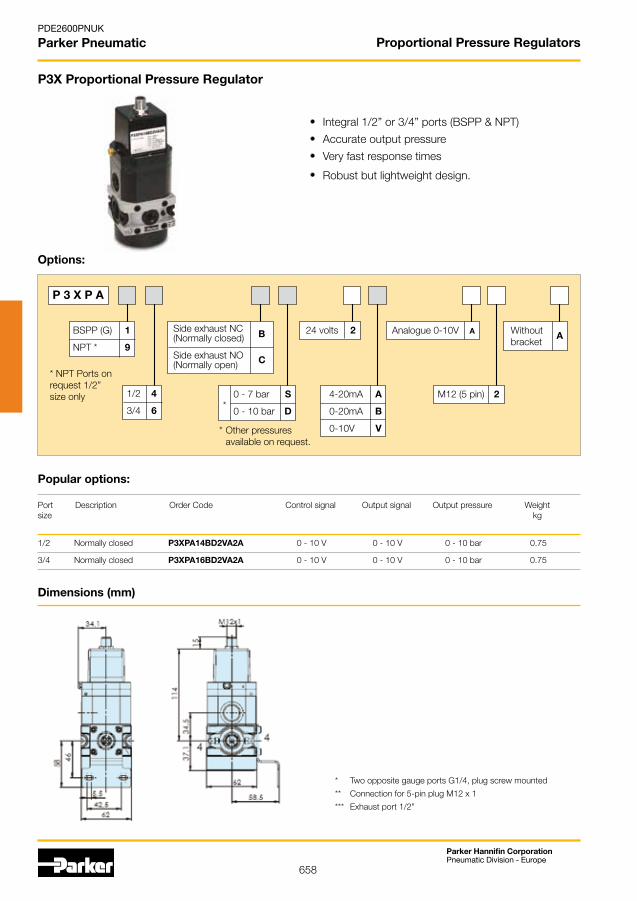
658
Parker Hannifin CorporationPneumatic Division - Europe
PDE2600PNUK
Parker Pneumatic Proportional Pressure Regulators
P3X Proportional Pressure Regulator
Options:
P 3 X P A
Side exhaust NC (Normally closed)
SideexhaustNO(Normally open)
B
C
BSPP (G) 1
NPT * 9
1/2 4
3/4 6
0 - 7 bar S
0 - 10 bar D
24 volts 2
4-20mA A
0-20mA B
0-10V V
Analogue 0-10V A
M12 (5 pin) 2
Withoutbracket
A
*Otherpressures available on request.
*
Port Description OrderCode Controlsignal Outputsignal Outputpressure Weightsize kg
1/2 Normally closed P3XPA14BD2VA2A 0 - 10 V 0 - 10 V 0 - 10 bar 0.75
3/4 Normally closed P3XPA16BD2VA2A 0 - 10 V 0 - 10 V 0 - 10 bar 0.75
Popular options:
Integral 1/2” or 3/4” ports (BSPP & NPT)
Accurate output pressure
Very fast response times
Robust but lightweight design.
* NPT Ports onrequest 1/2” size only
* Two opposite gauge ports G1/4, plug screw mounted
** Connection for 5-pin plug M12 x 1
*** Exhaust port 1/2”
Dimensions (mm)
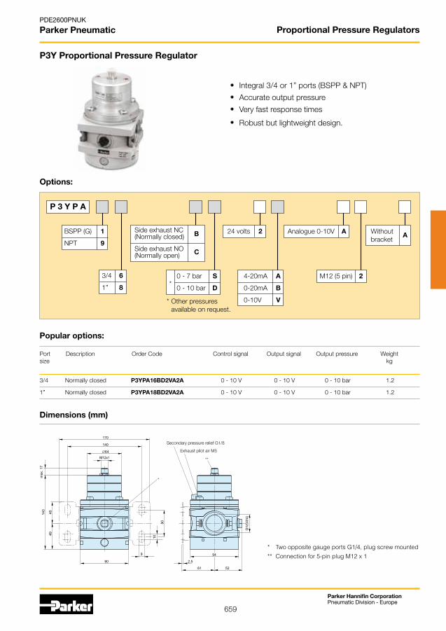
659
Parker Hannifin CorporationPneumatic Division - Europe
PDE2600PNUK
Parker Pneumatic Proportional Pressure Regulators
P3Y Proportional Pressure Regulator
Options:
P 3 Y P A
Side exhaust NC (Normally closed)
SideexhaustNO(Normally open)
B
C
BSPP (G) 1
NPT 9
3/4 6
1” 8
0 - 7 bar S
0 - 10 bar D
24 volts 2
4-20mA A
0-20mA B
0-10V V
Analogue 0-10V A
M12 (5 pin) 2
Withoutbracket
A
*Otherpressures available on request.
*
Port Description OrderCode Controlsignal Outputsignal Outputpressure Weightsize kg
3/4 Normally closed P3YPA16BD2VA2A 0 - 10 V 0 - 10 V 0 - 10 bar 1.2
1” Normally closed P3YPA18BD2VA2A 0 - 10 V 0 - 10 V 0 - 10 bar 1.2
Popular options:
Integral 3/4 or 1” ports (BSPP & NPT)
Accurate output pressure
Very fast response times
Robust but lightweight design.
Dimensions (mm)
* Two opposite gauge ports G1/4, plug screw mounted** Connection for 5-pin plug M12 x 1
Secondary pressure relief G1/8
Exhaust pilot air M5
**
*
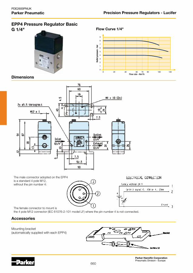
660
Parker Hannifin CorporationPneumatic Division - Europe
PDE2600PNUK
Parker Pneumatic
Dimensions
Accessories
Mounting bracket (automatically supplied with each EPP4)
EPP4 Pressure Regulator BasicG 1/4"
The female connector to mount is the 4 pole M12 connector (IEC 61076-2-101 model LF) where the pin number 4 is not connected.
The male connector adopted on the EPP4 is a standard 4 pole M12,without the pin number 4:
Precision Pressure Regulators - Lucifer
0 20 40 60 70 80 100 120
9
8
7
6
5
4
3
2
1
0
Flow rate - Nm3/h
Outle
t pre
ssur
e -
bar
Flow Curve 1/4"

661
Parker Hannifin CorporationPneumatic Division - Europe
PDE2600PNUK
Parker Pneumatic
Lucifer® EPP4 Basic and Comfort 1/4" and 1/2" Technical Data
Note: Parker reserves the right to change specifications without notification.
Fluids: Lubricated or non lubricated air and neutral gases Recommended filtration: 50 µm
Temperature range: Ambient: 0 to +50 °C Fluid: 0 to +50 °C
Inlet pressure range: 1 to 12 bar (the inlet pressure must always be at least 1 bar above the regulated pressure)
Outletpressurerange: 0.05 to 10 bar
Hysteresis: ± 50 mbar (factory set up)
Air consumption at constant 0control signal:
Supply voltage: 24 V DC ± 15 % (Max. ripple 1 V)
Power consumption: Max. 2.8 W with 24 V DC and constant changes of the control signal < 1.5 W without change of control signal
Control signal: Analog0-10V;standardfor0-10bar;adjustableforComfortversions Analog4-20mA;standardfor0-10bar;adjustableforComfortversions
Outletsensorsignal: Analog0-10V;standardfor0-10bar;adjustable(Comfortversionsonly) Analog4-20mA;standardfor0-10bar;adjustable Digital 0/24 V for alarm features: n Adjustablepressureerror(+/-) n AdjustabledelayON n AdjustabledelayOFF n Adjustablelogic(+/-)
Max. flow: G1/4: 70 m3/h G1/2: 150 m3/h
Indicative response time: With a volume of 330 cm³ at the outlet of the regulatorFilling 2 to 4 bar: G1/4 ~ 50 msec G1/2 ~ 60 msecFilling 2 to 8 bar: G1/4 ~ 100 msec G1/2 ~ 120 msecEmptying 4 to 2 bar: G1/4 ~ 70 msec G1/2 ~ 90 msecEmptying 8 to 2 bar: G1/4 ~ 130 msec G1/2 ~ 190 msec
Safety position: In case of control signal failure or if it is less than 50mV, the regulated pressure drops automatically to 0 bar (atmospheric pressure). In case of voltage supply failure, the regulated pressure will be kept constant.
Electrical connection: Basic: M12 - 4 pin; male connector power supply/control signal Comfort: M12 - 8 pin; male connector power supply/control signal M12 - 5 pin; male connector communication
Life expectancy: > 50 Mio changes of control signal steps
Mounting position: Indifferent (recommended position: upright; electronic part on top)
Resistance to vibrations: 30 g in all directions
Protection index: IP 65
Assembly: Silicone free
Electromagnetic compatibility: In accordance with EN 61000-6-1: 2001 EN 61000-6-2: 2001 EN 61000-6-3: 2001 + A11 2004 edition (01/07/07) EN 61000-6-4: 2001
Precision Pressure Regulators - Lucifer

662
Parker Hannifin CorporationPneumatic Division - Europe
PDE2600PNUK
Parker Pneumatic
491367 491366
Dimensions
EPP4 Pressure Regulator BasicG 1/2"
Accessories
Mounting bracket (to be ordered separately)
Supplied with 4 x M screws
Precision Pressure Regulators - Lucifer
0 25 50 75 100 125 150 175
9
8
7
6
5
4
3
2
1
0
Outle
t pre
ssur
e -
bar
Flow rate - Nm3/h
Flow Curve 1/2"

663
Parker Hannifin CorporationPneumatic Division - Europe
PDE2600PNUK
Parker Pneumatic
Reference Pipe Pressure range(bar)
Control signal(see options)
P4BG2001A002
P4BG2001A003
P4BG2001A004
P4BG2001A005
P4BG2001A006
P4BG2001A007
P4BG2001A008
P4BG2001A009
P4BG4001A002
P4BG4001A003
P4BG4001A004
P4BG4001A005
P4BG4001A008
P4BG4001A009
EPP4 Pressure Regulator BasicG 1/4" and G 1/2"
Ask your agent for any specific calibration.Ask your agent for the NPT version.Cable + connector not included.
Reference Pipe Pressure range(bar)
Control signal(see options)
P4BG2001A002 G 1/4 0 - 10 V 0 - 10 bar
P4BG2001A003 G 1/4 4 - 20 mA 0 - 10 bar
P4BG2001A004 G 1/4 0 - 10 V 0 - 6 bar
P4BG2001A005 G 1/4 4 - 20 MA 0 - 6 bar
P4BG2001A006 G 1/4 0 - 10 V 0 - 5 bar
P4BG2001A007 G 1/4 4 - 20 MA 0 - 5 bar
P4BG2001A008 G 1/4 0 - 10 V 0 - 7 bar
P4BG2001A009 G 1/4 4 - 20 MA 0 - 7 bar
P4BG4001A002 G 1/2 0 - 10V 0 – 10 BAR
P4BG4001A003 G 1/2 4 - 20MA 0 – 10 BAR
P4BG4001A004 G 1/2 0 - 10V 0 – 6 BAR
P4BG4001A005 G 1/2 4 - 20MA 0 – 6 BAR
P4BG4001A008 G 1/2 0 - 10V 0 – 7 BAR
P4BG4001A009 G 1/2 4 - 20MA 0 – 7 BAR
Precision Pressure Regulators - Lucifer
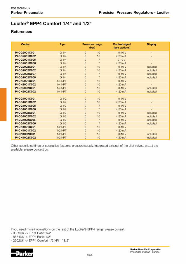
664
Parker Hannifin CorporationPneumatic Division - Europe
PDE2600PNUK
Parker Pneumatic
If you need more informations on the rest of the Lucifer® EPP4 range, please consult:- 8683UK -> EPP4 Basic 1/4"- 8684UK -> EPP4 Basic 1/2"-2202UK->EPP4Comfort1/2"HP,1"&2"
Lucifer® EPP4 Comfort 1/4" and 1/2"
References
Codes Pipe Pressure range Control signal Display (bar) (see options)
P4CG2001C001 G 1/4 0 10 0-10 V - P4CG2001C002 G 1/4 0 10 4-20 mA - P4CG2001C005 G 1/4 0 7 0-10 V - P4CG2001C006 G 1/4 0 7 4-20 mA - P4CG2002C001 G 1/4 0 10 0-10 V included P4CG2002C002 G 1/4 0 10 4-20 mA included P4CG2002C007 G 1/4 0 7 0-10 V included P4CG2002C008 G 1/4 0 7 4-20 mA included P4CN2001C001 1/4 NPT 0 10 0-10 V - P4CN2001C002 1/4 NPT 0 10 4-20 mA - P4CN2002C001 1/4 NPT 0 10 0-10 V included P4CN2002C002 1/4 NPT 0 10 4-20 mA included
P4CG4001C001 G 1/2 0 10 0-10 V - P4CG4001C002 G 1/2 0 10 4-20 mA - P4CG4001C005 G 1/2 0 7 0-10 V - P4CG4001C006 G 1/2 0 7 4-20 mA - P4CG4002C001 G 1/2 0 10 0-10 V included P4CG4002C002 G 1/2 0 10 4-20 mA included P4CG4002C005 G 1/2 0 7 0-10 V included P4CG4002C006 G 1/2 0 7 4-20 mA included P4CN4001C001 1/2 NPT 0 10 0-10 V - P4CN4001C002 1/2 NPT 0 10 4-20 mA - P4CN4002C001 1/2 NPT 0 10 0-10 V included P4CN4002C002 1/2 NPT 0 10 4-20 mA included
Otherspecificsettingsorspecialties(externalpressuresupply,integratedexhaustofthepilotvalves,etc…)areavailable, please contact us.
Precision Pressure Regulators - Lucifer

665
Parker Hannifin CorporationPneumatic Division - Europe
PDE2600PNUK
Parker Pneumatic
Lucifer® EPP4 Comfort 1/2" High Pressure,1"and 2" Technical Data
Note: Parker reserves the right to change specifications without notification.
Fluids: Lubricated or non lubricated air and neutral gases Recommended filtration: 50 µm
Temperature range: Ambient: 0 to +50 °C Fluid: 0 to +50 °C
Inlet pressure range: 1 to 12 bar - 1 to 14 bar - 1 to 21 bar (the inlet pressure must always be at least 1 bar above the regulated pressure)
Outletpressurerange: 0.05 to 10 bar, 0.1 to 1 bar, 0.1 to 20 bar
Hysteresis: ≤ 100 mbar if P inlet ≤ 10 bar ≤ 200 mbar if P inlet > 10 bar
Air consumption at constant Nonecontrol signal:
Supply voltage: 24 V DC ± 15 % (Max. ripple 1 V)
Power consumption: Max. 6 W with 24 V DC and constant changes of the control signal < 2 W without change of control signal
Control signal: Analog0-10V;standardfor0-10bar;adjustable Analog4-20mA;standardfor0-10bar;adjustable
Outletsensorsignal: Analog0-10V;standardfor0-10bar;adjustable Analog4-20mA;standardfor0-10bar;adjustable Digital 0/24 V for alarm features: n Adjustablepressureerror(+/-) n AdjustabledelayON n AdjustabledelayOFF n Adjustablelogic(+/-)
Max. flow: G1/2": 150 m3/h - G1": 1 000 m3/h - G2">2 700 m3/h
Indicative response time: With a volume of 330 cm³ at the outlet of the regulator G1/2" G1" G2"Filling 2 to 8 bar: ~120 msec ~250 msec ~250 msecEmptying 8 to 2 bar: ~190 msec ~400 msec ~400 msec
Safety position: In case of control signal failure or if it is less than 50mV, the regulated pressure drops automatically to 0 bar atmospheric pressure (for pressure ranges from 0-10bar, 100mV for pressure range over 10 bar).
In case of voltage supply failure, the regulated pressure will be kept constant.
Electrical connection: M12 - 8 pin; male connector power supply/control signal M12 - 5 pin; male connector communication
Life expectancy: > 20 Mio changes of control signal steps
Mounting position: Indifferent (recommended position: upright; electronic part on top)
Resistance to vibrations: 30 g in all directions
Protection index: IP 65
Assembly: Silicone free
Electromagnetic compatibility: In accordance with EN 61000-6-1: 2001 EN 61000-6-2: 2001 EN 61000-6-3: 2001 + A11 2004 edition (01/07/07) EN 61000-6-4: 2001
Precision Pressure Regulators - Lucifer
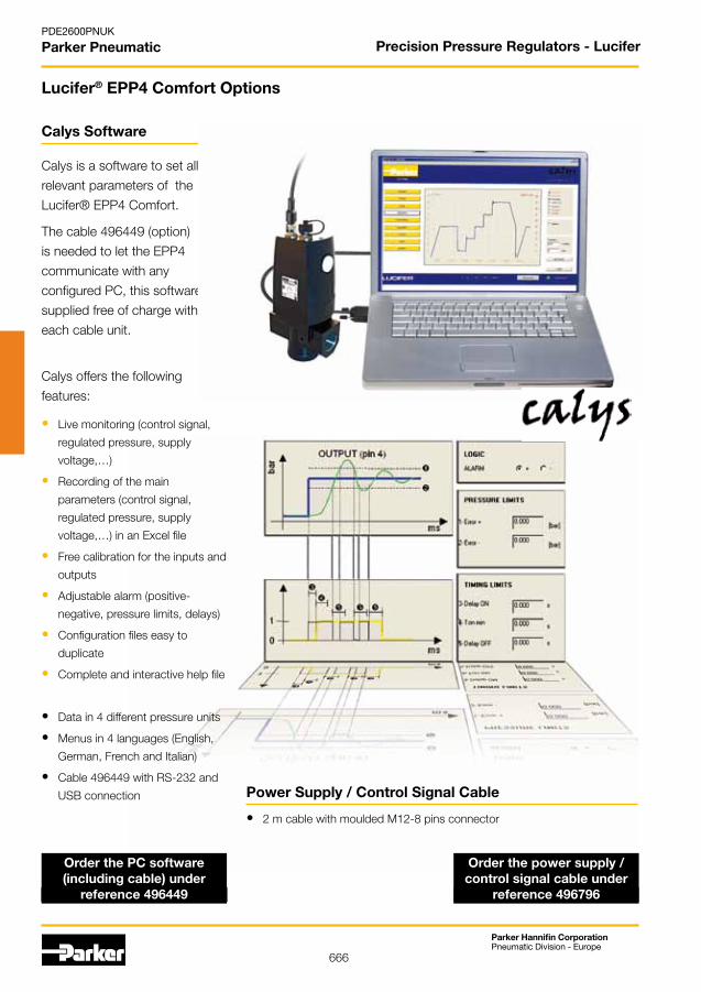
666
Parker Hannifin CorporationPneumatic Division - Europe
PDE2600PNUK
Parker Pneumatic
Calys is a software to set all
relevant parameters of the
Lucifer® EPP4 Comfort.
The cable 496449 (option)
is needed to let the EPP4
communicate with any
configured PC, this software is
supplied free of charge with
each cable unit.
Calys offers the following
features:
• Live monitoring (control signal,
regulated pressure, supply
voltage,…)
• Recording of the main
parameters (control signal,
regulated pressure, supply
voltage,…)inanExcelfile
• Free calibration for the inputs and
outputs
• Adjustablealarm(positive-
negative, pressure limits, delays)
• Configuration files easy to
duplicate
• Complete and interactive help file
• Data in 4 different pressure units
• Menus in 4 languages (English,
German, French and Italian)
• Cable 496449 with RS-232 and
USB connection
Calys Software
• 2 m cable with moulded M12-8 pins connector
Power Supply / Control Signal Cable
Order the PC software (including cable) under
reference 496449
Order the power supply / control signal cable under
reference 496796
Lucifer® EPP4 Comfort Options
Precision Pressure Regulators - Lucifer

667
Parker Hannifin CorporationPneumatic Division - Europe
PDE2600PNUK
Parker Pneumatic
Lucifer® EPP4 Comfort 1/2" HP, 1" and 2"
References
Codes Pipe Max inlet pressure Pressure range Control signal Dimensional (bar) (bar) (see options) Drawing
P4CG4101D001 G1/2 15 0 12 0-10V 1 P4CG4201D005 G1/2 21 0 16 0-10V 2 P4CG4201D003 G1/2 21 0 20 0-10V 2 P4CG4201D004 G1/2 21 0 20 4-20mA 2 P4CG6101C009 G1 12 0 3.5 4-20mA 3 P4CG6101C011 G1 12 0 5 0-10V 3 P4CG6101C010 G1 12 0 6 4-20mA 3 P4CG6101C001 G1 12 0 10 0-10V 3 P4CG6101C002 G1 12 0 10 4-20mA 3 P4CG6201D003 G1 21 0 20 0-10V 3 P4CG9101C012 G2 12 0 4 4-20mA 4 P4CG9101C010 G2 12 0 6 4-20mA 4 P4CG9101C001 G2 12 0 10 0-10V 4 P4CG9101C002 G2 12 0 10 4-20mA 4
Otherspecificsettingsorspecialties(externalpressuresupply,integratedexhaustofthepilotvalves,etc…)areavailable, please contact us.
If you need more informations on the rest of the Lucifer® EPP4 range, please consult:- 8683UK -> EPP4 Basic 1/4"- 8684UK -> EPP4 Basic 1/2"- 2201UK -> EPP4 Comfort 1/4" & 1/2"
Precision Pressure Regulators - Lucifer
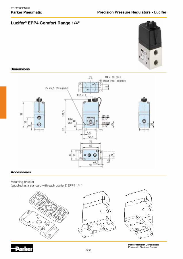
668
Parker Hannifin CorporationPneumatic Division - Europe
PDE2600PNUK
Parker Pneumatic
Dimensions
Accessories
Mounting bracket (supplied as a standard with each Lucifer® EPP4 1/4")
Lucifer® EPP4 Comfort Range 1/4"
Precision Pressure Regulators - Lucifer
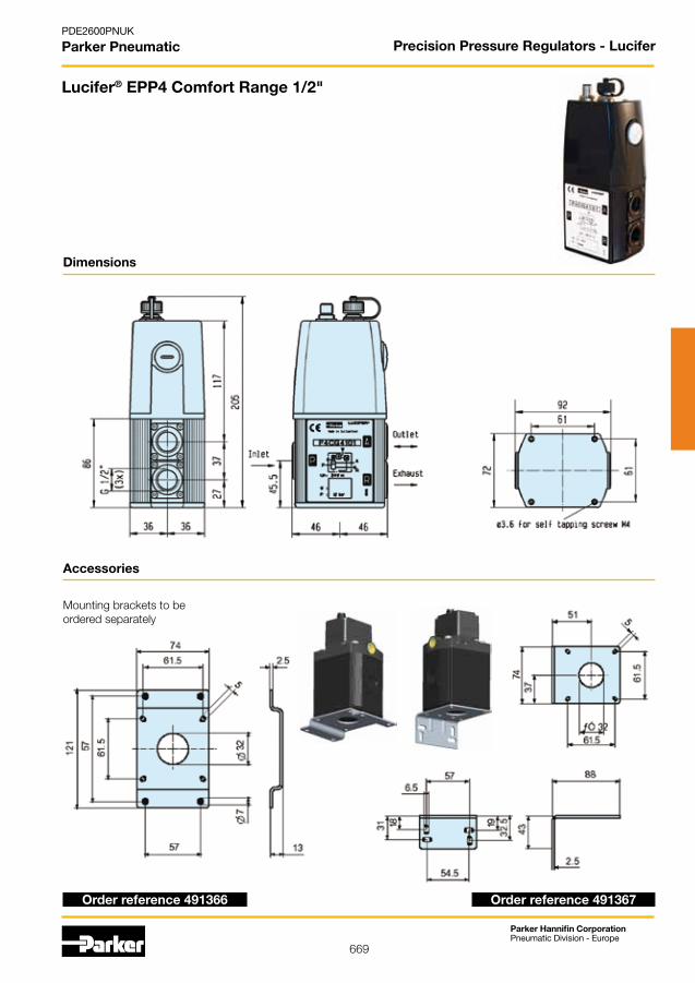
669
Parker Hannifin CorporationPneumatic Division - Europe
PDE2600PNUK
Parker Pneumatic
Dimensions
Lucifer® EPP4 Comfort Range 1/2"
Accessories
Mounting brackets to be ordered separately
Order reference 491367Order reference 491366
Precision Pressure Regulators - Lucifer

670
Parker Hannifin CorporationPneumatic Division - Europe
PDE2600PNUK
Parker Pneumatic
Dimensions
Lucifer® EPP4 Comfort Range 1/2"High Pressure 20 bar
Accessories
Mounting brackets to be ordered separately
Order reference 491367Order reference 491366
Precision Pressure Regulators - Lucifer
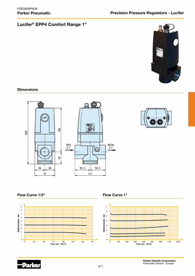
671
Parker Hannifin CorporationPneumatic Division - Europe
PDE2600PNUK
Parker Pneumatic
Dimensions
Lucifer® EPP4 Comfort Range 1"
Precision Pressure Regulators - Lucifer
0 160 320 480 640 800 960 1120 1280
7
6
5
4
3
2
1
0
Flow rate - Nm3/h
Outle
t pre
ssur
e -
bar
0 25 50 75 100 125 150 175
9
8
7
6
5
4
3
2
1
0
Outle
t pre
ssur
e -
bar
Flow rate - Nm3/h
Flow Curve 1"Flow Curve 1/2"

672
Parker Hannifin CorporationPneumatic Division - Europe
PDE2600PNUK
Parker Pneumatic
Dimensions
Lucifer® EPP4 Comfort Range 2"
Precision Pressure Regulators - Lucifer
0 300 600 900 1 200 1 500 1 800 2 100 2 400
7
6
5
4
3
2
1
0
Flow rate - Nm3/h
Outle
t pre
ssur
e -
bar
Flow Curve 2"
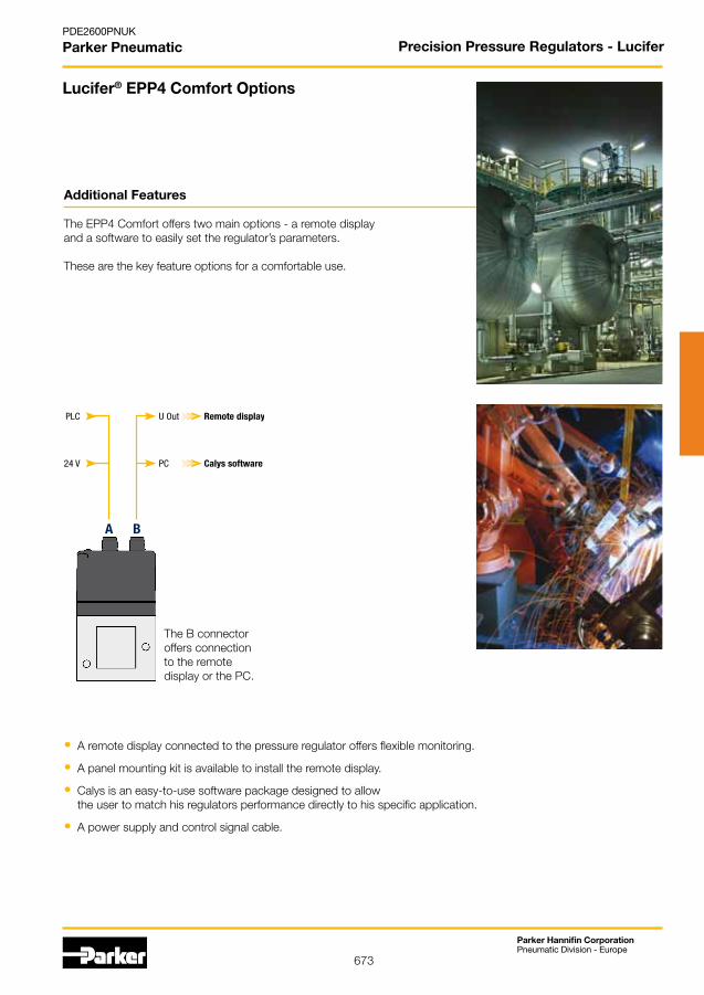
673
Parker Hannifin CorporationPneumatic Division - Europe
PDE2600PNUK
Parker Pneumatic
PLC
24 V
BA
U Out Remote display
PC Calys software
Additional Features
The EPP4 Comfort offers two main options - a remote display andasoftwaretoeasilysettheregulator’sparameters.
These are the key feature options for a comfortable use.
• A remote display connected to the pressure regulator offers flexible monitoring.
• A panel mounting kit is available to install the remote display.
• Calys is an easy-to-use software package designed to allow the user to match his regulators performance directly to his specific application.
• A power supply and control signal cable.
Lucifer® EPP4 Comfort Options
The B connector offers connection to the remote display or the PC.
Precision Pressure Regulators - Lucifer

674
Parker Hannifin CorporationPneumatic Division - Europe
PDE2600PNUK
Parker Pneumatic
3026.6
30
(10)
19
23 15 15
20
2-M3
5Panel Mounting Kit
Order the Panel Mounting Kit under reference 496610
Order the Remote Display under reference 496490
Lucifer® EPP4 Comfort Options
Remote Display
This option includes the Remote Display and 1.5 meter connecting cable.
Compact and highly readable remote LED display:
• Bar and PSI scales
• Security lock
• 1.5 m cable
• Mounting brackets
Precision Pressure Regulators - Lucifer
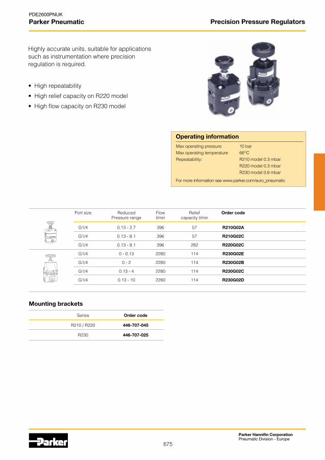
675
Parker Hannifin CorporationPneumatic Division - Europe
PDE2600PNUK
Parker Pneumatic
Port size Reduced Flow Relief Order code Pressure range l/min capacity l/min
G1/4 0.13 - 2.7 396 57 R210G02A
G1/4 0.13 - 8.1 396 57 R210G02C
G1/4 0.13 - 8.1 396 282 R220G02C
G1/4 0 - 0.13 2280 114 R230G02E G1/4 0 - 2 2280 114 R230G02B
G1/4 0.13 - 4 2280 114 R230G02C
G1/4 0.13 - 10 2280 114 R230G02D
• Highrepeatability
• HighreliefcapacityonR220model
• HighflowcapacityonR230model
Operating information
Max operating pressure 10 barMax operating temperature 66OCRepeatability: R210 model 0.3 mbar R220 model 0.3 mbar R230 model 0.6 mbar
Highlyaccurateunits,suitableforapplicationssuch as instrumentation where precisionregulation is required.
Series Order code
R210 / R220 446-707-045
R230 446-707-025
Mounting brackets
Precision Pressure Regulators
For more information see www.parker.com/euro_pneumatic
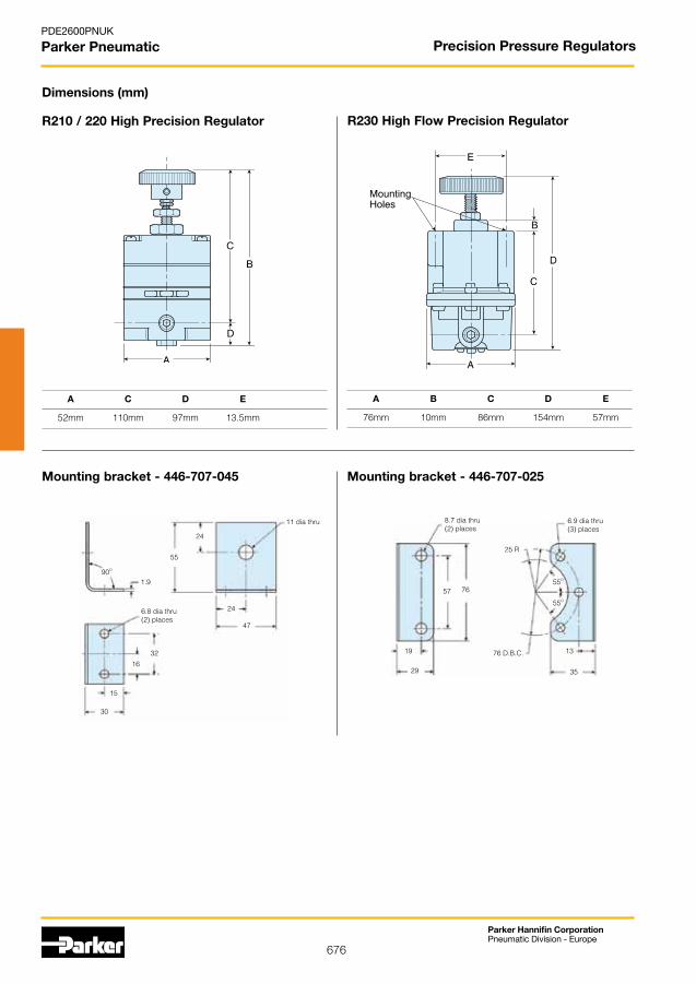
676
Parker Hannifin CorporationPneumatic Division - Europe
PDE2600PNUK
Parker Pneumatic
R210 / 220 High Precision Regulator
Dimensions (mm)
A C D E
52mm 110mm 97mm 13.5mm
R230 High Flow Precision Regulator
A B C D E
76mm 10mm 86mm 154mm 57mm
Mounting bracket - 446-707-045 Mounting bracket - 446-707-025
1.990O
55
24
11 dia thru
25 R
47
24
15
16
32
6.8 dia thru(2) places
30
19
57 76
76 D.B.C.
29
13
35
8.7 dia thru(2) places
6.9 dia thru(3) places
55O
55O
Precision Pressure Regulators
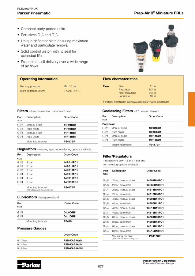
677
Parker Hannifin CorporationPneumatic Division - Europe
PDE2600PNUK
Parker Pneumatic
Order Code
0 - 2 bar P3D-KAB1AYN
0 - 4 bar P3D-KAB1ALN
0 - 8 bar P3D-KAB1ANN
Port Order Codesize
G1/8 04L00GB1
G1/4 04L10GB1
Port Description Order Code
size
G1/8 2 bar 14R010FC1
G1/8 4 bar 14R011FC1
G1/8 8 bar 14R013FC1
G1/4 2 bar 14R110FC1
G1/4 4 bar 14R111FC1
G1/4 8 bar 14R113FC1
Port Description Order Codesize
G1/8 Manual drain 14F01BB1
G1/8 Auto drain 14F05BB1
G1/4 Manual drain 14F11BB1
G1/4 Auto drain 14F15BB1
Port Description Order Codesize
Poly bowl
G1/8 Manual drain 10F01ED1
G1/8 Auto drain 10F05ED1
G1/4 Manual drain 10F11ED1
G1/4 Auto drain 10F15ED1
Port Description Order Codesize
G1/8 2 bar, manual drain 14E01B10FC1
G1/8 2 bar, auto drain 14E05B10FC1
G1/4 2 bar, manual drain 14E11B10FC1
G1/4 2 bar, auto drain 14E15B10FC1
G1/8 4 bar, manual drain 14E01B11FC1
G1/8 4 bar, auto drain 14E05B11FC1
G1/4 4 bar, manual drain 14E11B11FC1
G1/4 4 bar, auto drain 14E15B11FC1
G1/8 8 bar, manual drain 14E01B13FC1
G1/8 8 bar, auto drain 14E05B13FC1
G1/4 8 bar, manual drain 14E11B13FC1
G1/4 8 bar, auto drain 14E15B13FC1
• Compactbodyportedunits
• PortsizesG1/8 and G1/4
• Uniquedeflectorplateensuringmaximumwater and particulate removal
• Solidcontrolpistonwithlipsealfor extended life.
• Proportionaloildeliveryoverawiderangeof air flows.
Filters - 5 micron element, transparent bowl
Regulators - relieving type - non relieving options available
Coalescing Filters - 0.01 micron element
Filter/Regulators- transparent bowl - 2 and 4 bar andnon relieving options available
Lubricators - transparent bowl
Operating information
Working pressure: Max 10 bar
Working temperature: 0 °C to +52 °C
Flow characteristics
Flow Filter 11 l/s Regulator 9,3 l/s Filter Regulator 9,3 l/s Lubricator 10 l/s
Mounting bracket PS417BP Mounting bracket PS417BP
Mounting bracket PS417BP (Includes panel mounting nut)
Mounting bracket PS419
Pressure Gauges
Mounting bracket PS417BP (Includes panel mounting nut)
Prep-Air II® Miniature FRLs
For more information see www.parker.com/euro_pneumatic
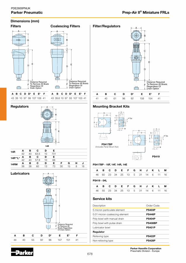
678
Parker Hannifin CorporationPneumatic Division - Europe
PDE2600PNUK
Parker Pneumatic
Description Order Code
5 micron particulate element PS403P
0.01 micron coalescing element PS446P
Poly bowl with manual drain PS404P
Poly bowl with pulse drain PS408BP
Lubricator bowl PS421P
Regulator
Relieving type PS422P
Non-relieving type PS428P
Dimensions (mm)
A B C D D† E E† F
43 39 10 97 99 107 108 41
Filters Coalescing Filters
Regulators
Filter/Regulators
Lubricators
A B C D E 42 40 63,5 10 731 A B C D E 42 40 57,9 10 68 A B C D E F G H J 38 38 60 13 73 30 15 8 18
14R
14R**L*
14RM
A B C D D† E E† F
41 40 61 96 92 158 154 41
A B C D D† E E† F
44 40 55 92 96 147 151 41
Service kits
PS417BP(Includes Panel Mount Nut)
PS419
Mounting Bracket Kits
A B C D D† E E† F
43 39,6 10 97 93 107 103 41
A B C D E F G H J K L M
46 55 23 34 25 13 5 31 14 6 11 16
PS419 - 04L
A B C D E F G H J K L M
46 60 23 34 25 13 5 31 14 6 11 16
PS417BP - 10F, 14F, 14R, 14E
Prep-Air II® Miniature FRLs

679
Parker Hannifin CorporationPneumatic Division - Europe
PDE2600PNUK
Parker Pneumatic
Port size Flow l/min Order code @ 7 bar fitted with 0-8.5 bar spring
450 PR364G02CSS PR354G02CSS 2820 PR10G04CSS PR11G04CSS
Port size Flow Filter Order code Order code l/min @ 7 bar element with manual drain with auto drain
G1/4 660 20µ PF504G02DHSS
G1/2 1800 40µ PF10G04DJSS PF10G04DJRSS
• SuitableforMarine&Offshoreapplications
• Chemical/Petroleumandprocessindustries
• Coalescingfiltersaredesignedforremovingoiland water aerosols down to 0.01µ
• Suitableforfoodindustryapplications
Particulate Filter 21
Manual drain Auto drain
21
* For 5µ filter element substitute H or J with G
Port size Flow Filter Order code Order code l/min @ 7 bar element with manual drain with auto drain
G1/4 240 0.3µ PF501G02DHSS
G1/2 480 0.01µ PF11G04DJSS PF11G04DJRSS
Coalescing Filter
Regulator
Port size Flow Order code l/min @ 7 bar
G1/2 3000 PL10G04DSS
Lubricator
Port size Order code G1/4 AC-2SS
G1/2 AC-4SS
Connectors
Stainless steel pressure gauge M1/4G40S-10 (0 to 10 bar)
3
2
21Panel mounting nut for G1/4: PR05X51SS G1/2: PR10X51SS
21
Operating information
Max operating pressure 20 bar 12 bar when fitted with auto-drainMax operating temperature Regulator 65OC Filter + Regulator 80OC, 50OC when fitted with auto-drain
The range of Stainless Steel FRLs are ideal for use in the food industry, the petrochemical or process industries or any application in a particularly harsh or aggressive environment.
Stainless Steel FRLs
Port size Flow l/min Order code @ 7 bar fitted with 0-8.5 bar spring
450 PB548G02DHCSS PB558G02DHCSS 1800 PB11G04DJCSS PB12G04DJCSS
Filter/Regulator
G1/4 Plasticbonnet/knob Full S/S versionG1/2 Plasticbonnet/knobFull S/S version
G1/4 Plasticbonnet/knob Full S/S versionG1/2 Plasticbonnet/knobFull S/S version
For more information see www.parker.com/euro_pneumatic

680
Parker Hannifin CorporationPneumatic Division - Europe
PDE2600PNUK
Parker Pneumatic
Distance required to remove all bowls
Distance required to remove all bowls
A C D E F
40mm 8mm 94mm 102mm 40mm
Dimensions (mm) - 1/4"
FiltersCoalescing Filters
Regulators
Filter/Regulators
A C C1 D E E1
40mm 51mm 65mm 13mm 64mm 78mm
A C C1 D E E1 F
40mm 55mm 67mm 92mm 78mm 147mm 40mm
Service kits
Port size Description Order Code
Filter
1/4 20 micron particulate element EK504Y
1/4 5 micron particulate element EK504VY
1/2 40 micron particulate element EK55J
1/2 5 micron particulate element EK55G
Coalescing Filter
1/4 0.3 micron coalescing element EKF501H
1/2 0.01 micron coalescing element EKF71
Regulator
1/4 Relieving type RKR364YSS
1/4 Non-relieving type RKR36KYSS
1/2 Relieving type RKR10YSS
1/2 Non-relieving type RKR10KYSS
Filter/Regulator
1/4 20 micron particulate element EK504Y
1/4 5 micron particulate element EK504VY
1/2 40 micron particulate element EKF10Y
1/2 5 micron particulate element EKF10VY
Lubricator
Sight dome kit RKL10SS
Stainless Steel FRLs
PB548 PB558
C1
E1
D
ADia.
CE
D
ADia.
PR354PR364
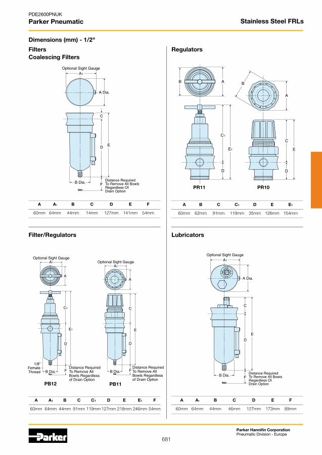
681
Parker Hannifin CorporationPneumatic Division - Europe
PDE2600PNUK
Parker Pneumatic
A A1 B C D E F
60mm 64mm 44mm 14mm 127mm 141mm 54mm
Dimensions (mm) - 1/2"
FiltersCoalescing Filters
Regulators
Filter/Regulators Lubricators
A B C C1 D E E1
60mm 62mm 91mm 119mm 35mm 126mm 154mm
A A1 B C C1 D E E1 F
60mm 64mm 44mm 91mm 119mm 127mm 218mm 246mm 54mm
A A1 B C D E F
60mm 64mm 44mm 46mm 127mm 173mm 89mm
Stainless Steel FRLs
A
B
C
E
D
AB
C1
E1
D
PR11 PR10
PB11
D
E
C
B Dia.Distance RequiredTo Remove All Bowls Regardless of Drain Option
F
A
Optional Sight GaugeA1
1/8”FemaleThread
PB12
D
E1
C1
B Dia.Distance RequiredTo Remove All Bowls Regardless of Drain Option
F
Optional Sight GaugeA1
A
1/8”FemaleThread
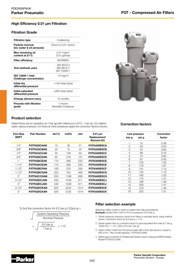
682
Parker Hannifin CorporationPneumatic Division - Europe
PDE2600PNUK
Parker Pneumatic
Fitration Grade
Filtration type Coalescing
Particle removal Down to 0.01 micron (inc water & oil aerosols)
Max remaining oil 0.01 mg/m3
content at 21°C 0.01 ppm(w)
Filter efficiency 99.9999%
ISO8573.2 Test methods used ISO8573.4 ISO12500-1
ISO 12500-1 Inlet 10 mg/m3
Challenge concentration
Initial dry <140 mbar (2psi) differential pressure
Initial saturated <200 mbar (3psi) differential pressure
Change element every 12 months
Precede with filtration 1 micron grade Moduflex Coalescer
High Efficiency 0.01 µm Filtration
Correction factors
To find the correction factor for 8.5 bar g (122psi g) =
SystemOperatingPressure
Nominal Pressure
8.5 bar g
7 bar g= 1.10=
Selecting a filter model to match a system flow rate and pressure. Example: System flow 1050 m3/hr at a pressure of 8.5 bar g
1. Obtainpressurecorrectionfactorfromtableorcalculatefactorusingmethod shown. Correction factor for 8.5 bar g = 1.10
2. Divide system flow by correction factor to give equivalent flow rate at 7 bar g 1050m3/hr ÷ 1.10 = 955 m3/hr (at 7 bar g)
3. Select a filter model from the above table with a flow rate above or equal to 955 m3/hr.Filtermodelselected:P3TFA2CCHAN
4. Select pipe connection & Thread type System uses 2" piping and BSP threads: ModelP3TFA2CCHAN
Filter selection example
Port Size Part Number dm3/s m3/hr cfm 0.01 µm BSPT Replacement Element Kit
1/4” P3TFA22CAAN 10 36 21 P3TKA00ESCA
3/8” P3TFA23CBAN 20 72 42 P3TKA00ESCB
1/2” P3TFA24CCAN 30 108 64 P3TKA00ESCC
3/4” P3TFA26CDAN 60 216 127 P3TKA00ESCD
1 “ P3TFA28CEAN 110 396 233 P3TKA00ESCE
1.1/4” P3TFA2ACEAN 110 396 233 P3TKA00ESCE
1.1/2” P3TFA2BCFAN 160 576 339 P3TKA00ESCF
1.1/2” P3TFA2BCGAN 220 792 466 P3TKA00ESCG
2” P3TFA2CCHAN 330 1188 699 P3TKA00ESCH
2.1/2” P3TFA2DCJAN 430 1548 911 P3TKA00ESCJ
3” P3TFA2ECJAN 430 1548 911 P3TKA00ESCJ
2.1/2” P3TFA2DCKAN 620 2232 1314 P3TKA00ESCK
3” P3TFA2ECKAN 620 2232 1314 P3TKA00ESCK
Product selectionStated flows are for operation at 7 bar (g) with reference to 20°C, 1 bar (a), 0% relative water vapour pressure. For flows at other pressures apply the correction factors shown.
Line pressure Correction bar g psi g factor
1 15 0.38 2 29 0.53 3 44 0.65 4 58 0.76 5 73 0.85 6 87 0.93 7 100 1.00 8 116 1.07 9 131 1.13 10 145 1.19 11 160 1.25 12 174 1.31 13 189 1.36 14 203 1.41 15 218 1.46 16 232 1.51
P3T - Compressed Air Filters

683
Parker Hannifin CorporationPneumatic Division - Europe
PDE2600PNUK
Parker Pneumatic
Technical data
Weights and dimensions
Port A B C D E F G Weight Size Part Number BSPT mm ins mm ins mm ins mm ins mm ins mm ins mm ins kg lbs
1/4” P3TFA22CAAN 76.0 3.0 181.5 7.2 153.0 6.0 18.0 0.71 24.5 0.96 30.0 1.18 52.0 2.05 0.4 0.9
3/8” P3TFA23CBAN 97.5 3.8 235.0 9.3 201.0 7.9 20.5 0.81 25.5 1.00 40.0 1.57 60.0 2.36 1.0 2.2
1/2” P3TFA24CCAN 97.5 3.8 235.0 9.3 201.0 7.9 20.5 0.81 25.5 1.00 40.0 1.57 60.0 2.36 1.0 2.2
3/4” P3TFA26CDAN 129.0 5.1 275.0 10.8 232.5 9.2 23.0 0.91 28.0 1.10 60.0 2.36 68.0 2.68 2.2 4.8
1 “ P3TFA28CEAN 129.0 5.1 364.5 14.3 322.0 12.7 23.0 0.91 28.0 1.10 60.0 2.36 68.0 2.68 2.6 5.7
1.1/4” P3TFA2ACEAN 129.0 5.1 364.5 14.3 322.0 12.7 23.0 0.91 28.0 1.10 60.0 2.36 68.0 2.68 2.6 5.7
1.1/2” P3TFA2BCFAN 170.0 6.7 432.5 17.0 382.5 15.1 32.0 1.26 39.0 1.54 84.0 3.31 92.0 3.62 4.5 9.9
1.1/2” P3TFA2BCGAN 170.0 6.7 524.5 20.6 474.5 18.7 32.0 1.26 39.0 1.54 84.0 3.31 92.0 3.62 5.3 11.6
2” P3TFA2CCHAN 170.0 6.7 524.5 20.6 474.5 18.7 32.0 1.26 39.0 1.54 84.0 3.31 92.0 3.62 5.3 11.6
2.1/2” P3TFA2DCJAN 205.0 8.1 641.5 25.3 581.5 22.9 35.5 1.40 42.5 1.67 100.0 3.94 135.0 5.31 10.0 22.0
3” P3TFA2ECJAN 205.0 8.1 641.5 25.3 581.5 22.9 35.5 1.40 42.5 1.67 100.0 3.94 135.0 5.31 10.0 22.0
2.1/2” P3TFA2DCKAN 205.0 8.1 832.0 32.8 772.0 30.4 35.5 1.40 42.5 1.67 100.0 3.94 135.0 5.31 12.0 26.4
3” P3TFA2ECKAN 205.0 8.1 832.0 32.8 772.0 30.4 35.5 1.40 42.5 1.67 100.0 3.94 135.0 5.31 12.0 26.4
Filter Drain Max operating Max Min Grade type pressure recommended recommended bar g psi g operating temp. operating temp.
0.01 micron Auto 16 232 80°C 176°F 1.5°C 35°F
Used to indicate premature high differential pressure. Indicator can be retrofitted to existing housings without depressurising the system.
Fixing clamp allows quick and simple connection of multiple filter housings.
Mounting brackets provide additional support to filters installed in flexible piping systems or OEMequipment.
Wall Mounting Bracket Kit
Modular Connection Kit
Incident Monitor
High Efficiency 0.01 µm Filtration
Optional Accessories
Modular Wall Mounting Connection Bracket Kit Kit
P3TKA00CBA P3TKA00MWA
P3TKA00CBB P3TKA00MWB
P3TKA00CBB P3TKA00MWB
P3TKA00CBD P3TKA00MWD
P3TKA00CBD P3TKA00MWD
P3TKA00CBD P3TKA00MWD
P3TKA00CBF P3TKA00MWF
P3TKA00CBF P3TKA00MWF
P3TKA00CBF P3TKA00MWF
P3TKA00CBJ P3TKA00MWJ
P3TKA00CBJ P3TKA00MWJ
P3TKA00CBJ P3TKA00MWJ
P3TKA00CBJ P3TKA00MWJ
DPI Kit
P3TKA00RQ
G
A
B
C
D
E
F
D
E
Drain Kits
Auto drain P3TKA00DA
Manual drain P3TKA00DM
P3T - Compressed Air Filters

684
Parker Hannifin CorporationPneumatic Division - Europe
PDE2600PNUK
Parker Pneumatic
To find the correction factor for 8.5 bar g (122psi g) =
SystemOperatingPressure
Nominal Pressure
8.5 bar g
7 bar g= 1.10=
Selecting a filter model to match a system flow rate and pressure. Example: System flow 1050 m3/hr at a pressure of 8.5 bar g
1. Obtainpressurecorrectionfactorfromtableorcalculatefactorusingmethod shown. Correction factor for 8.5 bar g = 1.10
2. Divide system flow by correction factor to give equivalent flow rate at 7 bar g 1050m3/hr ÷ 1.10 = 955 m3/hr (at 7 bar g)
3. Select a filter model from the above table with a flow rate above or equal to 955 m3/hr.Filtermodelselected:P3TFA2C9HAN
4. Select pipe connection & Thread type System uses 2" piping and BSP threads: ModelP3TFA2C9HAN
Filter selection example
Fitration Grade
Filtration type Coalescing
Particle removal Down to 1 micron (inc water & oil aerosols)
Max remaining oil 0.06 mg/m3
content at 21°C 0.05 ppm(w)
Filter efficiency 99.925%
ISO8573.2 Test methods used ISO8573.4 ISO12500-1
ISO 12500-1 Inlet 40 mg/m3
Challenge concentration
Initial dry <70 mbar (2psi) differential pressure
Initial saturated <140 mbar (3psi) differential pressure
Change element every 12 months
Precede with filtration 1 micron grade Moduflex Coalescer
1 µm Filtration
Correction factors
Port Size Part Number dm3/s m3/hr cfm 1 µm BSPT Replacement Element Kit
1/4” P3TFA229AAN 10 36 21 P3TKA00ES9A
3/8” P3TFA239BAN 20 72 42 P3TKA00ES9B
1/2” P3TFA249CAN 30 108 64 P3TKA00ES9C
3/4” P3TFA269DAN 60 216 127 P3TKA00ES9D
1 “ P3TFA289EAN 110 396 233 P3TKA00ES9E
1.1/4” P3TFA2A9EAN 110 396 233 P3TKA00ES9E
1.1/2” P3TFA2B9FAN 160 576 339 P3TKA00ES9F
1.1/2” P3TFA2B9GAN 220 792 466 P3TKA00ES9G
2” P3TFA2C9HAN 330 1188 699 P3TKA00ES9H
2.1/2” P3TFA2D9JAN 430 1548 911 P3TKA00ES9J
3” P3TFA2E9JAN 430 1548 911 P3TKA00ES9J
2.1/2” P3TFA2D9KAN 620 2232 1314 P3TKA00ES9K
3” P3TFA2E9KAN 620 2232 1314 P3TKA00ES9K
Product selectionStated flows are for operation at 7 bar (g) with reference to 20°C, 1 bar (a), 0% relative water vapour pressure. For flows at other pressures apply the correction factors shown.
Line pressure Correction bar g psi g factor
1 15 0.38 2 29 0.53 3 44 0.65 4 58 0.76 5 73 0.85 6 87 0.93 7 100 1.00 8 116 1.07 9 131 1.13 10 145 1.19 11 160 1.25 12 174 1.31 13 189 1.36 14 203 1.41 15 218 1.46 16 232 1.51
P3T - Compressed Air Filters

685
Parker Hannifin CorporationPneumatic Division - Europe
PDE2600PNUK
Parker Pneumatic
Used to indicate premature high differential pressure. Indicator can be retrofitted to existing housings without depressurising the system.
Fixing clamp allows quick and simple connection of multiple filter housings.
Mounting brackets provide additional support to filters installed in flexible piping systems or OEMequipment.
Wall Mounting Bracket Kit
Modular Connection Kit
Incident Monitor
G
A
B
C
D
E
F
D
E
Technical data
Weights and dimensions
Port A B C D E F G Weight Size Part Number BSPT mm ins mm ins mm ins mm ins mm ins mm ins mm ins kg lbs
1/4” P3TFA229AAN 76.0 3.0 181.5 7.2 153.0 6.0 18.0 0.71 24.5 0.96 30.0 1.18 52.0 2.05 0.4 0.9
3/8” P3TFA239BAN 97.5 3.8 235.0 9.3 201.0 7.9 20.5 0.81 25.5 1.00 40.0 1.57 60.0 2.36 1.0 2.2
1/2” P3TFA249CAN 97.5 3.8 235.0 9.3 201.0 7.9 20.5 0.81 25.5 1.00 40.0 1.57 60.0 2.36 1.0 2.2
3/4” P3TFA269DAN 129.0 5.1 275.0 10.8 232.5 9.2 23.0 0.91 28.0 1.10 60.0 2.36 68.0 2.68 2.2 4.8
1 “ P3TFA289EAN 129.0 5.1 364.5 14.3 322.0 12.7 23.0 0.91 28.0 1.10 60.0 2.36 68.0 2.68 2.6 5.7
1.1/4” P3TFA2A9EAN 129.0 5.1 364.5 14.3 322.0 12.7 23.0 0.91 28.0 1.10 60.0 2.36 68.0 2.68 2.6 5.7
1.1/2” P3TFA2B9FAN 170.0 6.7 432.5 17.0 382.5 15.1 32.0 1.26 39.0 1.54 84.0 3.31 92.0 3.62 4.5 9.9
1.1/2” P3TFA2B9GAN 170.0 6.7 524.5 20.6 474.5 18.7 32.0 1.26 39.0 1.54 84.0 3.31 92.0 3.62 5.3 11.6
2” P3TFA2C9HAN 170.0 6.7 524.5 20.6 474.5 18.7 32.0 1.26 39.0 1.54 84.0 3.31 92.0 3.62 5.3 11.6
2.1/2” P3TFA2D9JAN 205.0 8.1 641.5 25.3 581.5 22.9 35.5 1.40 42.5 1.67 100.0 3.94 135.0 5.31 10.0 22.0
3” P3TFA2E9JAN 205.0 8.1 641.5 25.3 581.5 22.9 35.5 1.40 42.5 1.67 100.0 3.94 135.0 5.31 10.0 22.0
2.1/2” P3TFA2D9KAN 205.0 8.1 832.0 32.8 772.0 30.4 35.5 1.40 42.5 1.67 100.0 3.94 135.0 5.31 12.0 26.4
3” P3TFA2E9KAN 205.0 8.1 832.0 32.8 772.0 30.4 35.5 1.40 42.5 1.67 100.0 3.94 135.0 5.31 12.0 26.4
Filter Drain Max operating Max Min Grade type pressure recommended recommended bar g psi g operating temp. operating temp.
1 micron Auto 16 232 80°C 176°F 1.5°C 35°F
1 µm Filtration
Optional Accessories
Modular Wall Mounting Connection Bracket Kit Kit
P3TKA00CBA P3TKA00MWA
P3TKA00CBB P3TKA00MWB
P3TKA00CBB P3TKA00MWB
P3TKA00CBD P3TKA00MWD
P3TKA00CBD P3TKA00MWD
P3TKA00CBD P3TKA00MWD
P3TKA00CBF P3TKA00MWF
P3TKA00CBF P3TKA00MWF
P3TKA00CBF P3TKA00MWF
P3TKA00CBJ P3TKA00MWJ
P3TKA00CBJ P3TKA00MWJ
P3TKA00CBJ P3TKA00MWJ
P3TKA00CBJ P3TKA00MWJ
DPI Kit
P3TKA00RQ
Drain Kits
Auto drain P3TKA00DA
Manual drain P3TKA00DM
P3T - Compressed Air Filters

686
Parker Hannifin CorporationPneumatic Division - Europe
PDE2600PNUK
Parker Pneumatic
To find the correction factor for 8.5 bar g (122psi g) =
SystemOperatingPressure
Nominal Pressure
8.5 bar g
7 bar g= 1.10=
Selecting a filter model to match a system flow rate and pressure. Example: System flow 1050 m3/hr at a pressure of 8.5 bar g
1. Obtainpressurecorrectionfactorfromtableorcalculatefactorusingmethod shown. Correction factor for 8.5 bar g = 1.10
2. Divide system flow by correction factor to give equivalent flow rate at 7 bar g 1050m3/hr ÷ 1.10 = 955 m3/hr (at 7 bar g)
3. Select a filter model from the above table with a flow rate above or equal to 955 m3/hr.Filtermodelselected:P3TFA2CAHMN
4. Select pipe connection & Thread type System uses 2" piping and BSP threads: ModelP3TFA2CAHMN
Filtration type Oilvapourremoval
Particle removal N/A (inc water & oil aerosols)
Max remaining oil 0.003 mg/m3
content at 21°C 0.003 ppm(w)
Filter efficiency N/A
Test methods used ISO8573.5
ISO 12500-1 Inlet N/A Challenge concentration
Initial dry <200 mbar (3psi) differential pressure
Initial saturated N/A differential pressure
Change element every When oil vapour is detected
Precede with filtration 0.01 micron grade Moduflex Coalescer filter
Fitration Grade
Oil Vapour Removal Filter
Correction factors
Filter selection example
Product selectionStated flows are for operation at 7 bar (g) with reference to 20°C, 1 bar (a), 0% relative water vapour pressure. For flows at other pressures apply the correction factors shown.
Port Size Part Number dm3/s m3/hr cfm Oil vapour removal BSPT Replacement Element Kit
1/4” P3TFA22AAMN 10 36 21 P3TKA00ESAA
3/8” P3TFA23ABMN 20 72 42 P3TKA00ESAB
1/2” P3TFA24ACMN 30 108 64 P3TKA00ESAC
3/4” P3TFA26ADMN 60 216 127 P3TKA00ESAD
1 “ P3TFA28AEMN 110 396 233 P3TKA00ESAE
1.1/4” P3TFA2AAEMN 110 396 233 P3TKA00ESAE
1.1/2” P3TFA2BAFMN 160 576 339 P3TKA00ESAF
1.1/2” P3TFA2BAGMN 220 792 466 P3TKA00ESAG
2” P3TFA2CAHMN 330 1188 699 P3TKA00ESAH
2.1/2” P3TFA2DAJMN 430 1548 911 P3TKA00ESAJ
3” P3TFA2EAJMN 430 1548 911 P3TKA00ESAJ
2.1/2” P3TFA2DAKMN 620 2232 1314 P3TKA00ESAK
3” P3TFA2EAKMN 620 2232 1314 P3TKA00ESAK
Line pressure Correction bar g psi g factor
1 15 0.38 2 29 0.53 3 44 0.65 4 58 0.76 5 73 0.85 6 87 0.93 7 100 1.00 8 116 1.07 9 131 1.13 10 145 1.19 11 160 1.25 12 174 1.31 13 189 1.36 14 203 1.41 15 218 1.46 16 232 1.51 17 247 1.56 18 261 1.60 19 275 1.65 20 290 1.70
P3T - Compressed Air Filters
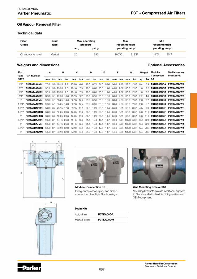
687
Parker Hannifin CorporationPneumatic Division - Europe
PDE2600PNUK
Parker Pneumatic
Fixing clamp allows quick and simple connection of multiple filter housings.
Mounting brackets provide additional support to filters installed in flexible piping systems or OEMequipment.
Wall Mounting Bracket KitModular Connection Kit
G
A
B
C
D
E
F
D
E
Technical data
Weights and dimensions
Port A B C D E F G Weight Size Part Number BSPT mm ins mm ins mm ins mm ins mm ins mm ins mm ins kg lbs
1/4” P3TFA22AAMN 76.0 3.0 181.5 7.2 153.0 6.0 18.0 0.71 24.5 0.96 30.0 1.18 52.0 2.05 0.4 0.9
3/8” P3TFA23ABMN 97.5 3.8 235.0 9.3 201.0 7.9 20.5 0.81 25.5 1.00 40.0 1.57 60.0 2.36 1.0 2.2
1/2” P3TFA24ACMN 97.5 3.8 235.0 9.3 201.0 7.9 20.5 0.81 25.5 1.00 40.0 1.57 60.0 2.36 1.0 2.2
3/4” P3TFA26ADMN 129.0 5.1 275.0 10.8 232.5 9.2 23.0 0.91 28.0 1.10 60.0 2.36 68.0 2.68 2.2 4.8
1 “ P3TFA28AEMN 129.0 5.1 364.5 14.3 322.0 12.7 23.0 0.91 28.0 1.10 60.0 2.36 68.0 2.68 2.6 5.7
1.1/4” P3TFA2AAEMN 129.0 5.1 364.5 14.3 322.0 12.7 23.0 0.91 28.0 1.10 60.0 2.36 68.0 2.68 2.6 5.7
1.1/2” P3TFA2BAFMN 170.0 6.7 432.5 17.0 382.5 15.1 32.0 1.26 39.0 1.54 84.0 3.31 92.0 3.62 4.5 9.9
1.1/2” P3TFA2BAGMN 170.0 6.7 524.5 20.6 474.5 18.7 32.0 1.26 39.0 1.54 84.0 3.31 92.0 3.62 5.3 11.6
2” P3TFA2CAHMN 170.0 6.7 524.5 20.6 474.5 18.7 32.0 1.26 39.0 1.54 84.0 3.31 92.0 3.62 5.3 11.6
2.1/2” P3TFA2DAJMN 205.0 8.1 641.5 25.3 581.5 22.9 35.5 1.40 42.5 1.67 100.0 3.94 135.0 5.31 10.0 22.0
3” P3TFA2EAJMN 205.0 8.1 641.5 25.3 581.5 22.9 35.5 1.40 42.5 1.67 100.0 3.94 135.0 5.31 10.0 22.0
2.1/2” P3TFA2DAKMN 205.0 8.1 832.0 32.8 772.0 30.4 35.5 1.40 42.5 1.67 100.0 3.94 135.0 5.31 12.0 26.4
3” P3TFA2EAKMN 205.0 8.1 832.0 32.8 772.0 30.4 35.5 1.40 42.5 1.67 100.0 3.94 135.0 5.31 12.0 26.4
Filter Drain Max operating Max Min Grade type pressure recommended recommended bar g psi g operating temp. operating temp.
Oilvapourremoval Manual 20 290 100°C 212°F 1.5°C 35°F
Oil Vapour Removal Filter
Optional Accessories
Modular Wall Mounting Connection Bracket Kit Kit
P3TKA00CBA P3TKA00MWA
P3TKA00CBB P3TKA00MWB
P3TKA00CBB P3TKA00MWB
P3TKA00CBD P3TKA00MWD
P3TKA00CBD P3TKA00MWD
P3TKA00CBD P3TKA00MWD
P3TKA00CBF P3TKA00MWF
P3TKA00CBF P3TKA00MWF
P3TKA00CBF P3TKA00MWF
P3TKA00CBJ P3TKA00MWJ
P3TKA00CBJ P3TKA00MWJ
P3TKA00CBJ P3TKA00MWJ
P3TKA00CBJ P3TKA00MWJ
Drain Kits
Auto drain P3TKA00DA
Manual drain P3TKA00DM
P3T - Compressed Air Filters

688
Parker Hannifin CorporationPneumatic Division - Europe
PDE2600PNUK
Parker Pneumatic
High Efficiency Bulk Liquid Removal
To find the correction factor for 8 bar g =
SystemOperatingPressure
Nominal Pressure
8 bar g
7 bar g= 1.06=
Line pressure Correction bar g psi g factor
1 15 0.25 2 29 0.38 3 44 0.50 4 58 0.63 5 73 0.75 6 87 0.88 7 100 1.00 8 116 1.06 9 131 1.12 10 145 1.17 11 160 1.22 12 174 1.27 13 189 1.32 14 203 1.37 15 218 1.41 16 232 1.46
Correction factors
Selecting a Water Separator model to match a system flow rate and pressure. Example: System flow 1050 m3/hr at a pressure of 8 bar g
1. Obtainpressurecorrectionfactorfromtable. Correction factor for 8 bar g = 1.06
2. Divide system flow by correction factor to give equivalent flow rate at 7 bar g 1050m3/hr ÷ 1.06 = 984 m3/hr (at 7 bar g)
3. Select a filter model from the above table with a flow rate above or equal to 984 m3/hr. Suitable Water Separator models : P3TFA2AWFAN P3TFA2AWGAN P3TFA2AWHAN
4. Select pipe connection & Thread type System uses 1.1/2" piping and BSP threads: Model P3TFA2BWGAN
Filter selection example
1/4” P3TFA22WAAN 10 36 21 16 232 80 C 176 F 1.5 C 35 F
3/8” P3TFA23WBAN 40 144 85 16 232 80 C 176 F 1.5 C 35 F
1/2” P3TFA24WCAN 40 144 85 16 232 80 C 176 F 1.5 C 35 F
3/4” P3TFA26WDAN 110 396 233 16 232 80 C 176 F 1.5 C 35 F
1” P3TFA28WEAN 110 396 233 16 232 80 C 176 F 1.5 C 35 F
1.1/4” P3TFA2AWFAN 350 1260 742 16 232 80 C 176 F 1.5 C 35 F
1.1/2” P3TFA2BWGAN 350 1260 742 16 232 80 C 176 F 1.5 C 35 F
2” P3TFA2CWHAN 350 1260 742 16 232 80 C 176 F 1.5 C 35 F
2.1/2” P3TFA2DWKAN 800 2880 1695 16 232 80 C 176 F 1.5 C 35 F
3” P3TFA2EWKAN 800 2880 1695 16 232 80 C 176 F 1.5 C 35 F
Product selectionStated flows are for operation at 7 bar (g) with reference to 20°C, 1 bar (a), 0% relative water vapour pressure.
• TestedinaccordancewithISO8573.9
• Performance independently verified by Lloyds Register
• High liquid removal efficiencies at all flow conditions
• Low pressure losses for low operational costs
• Multiple port sizes for a given flow rate provides increased flexibility during installation
• Suitable for variable flow compressors
• Works with all types of compressor and compressor condensate
• Low maintenance
• 10YearHousingGuarantee
Typical Applications
• Bulk liquid removal at any point in a compressed air system
• Protection of refrigeration and adsorption dryer pre-filtration
• Liquid removal from compressor inter-coolers / after-coolers
• Liquid separation within refrigeration dryers
Port Size Part Number dm3/s m3/hr cfm Max operating pressure Max Operating Min Operating temperature temperature bar g psi g
P3T - Compressed Air Filters
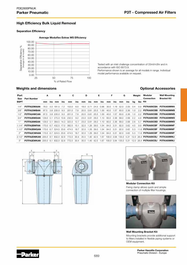
689
Parker Hannifin CorporationPneumatic Division - Europe
PDE2600PNUK
Parker Pneumatic
Separation Efficiency
Fixing clamp allows quick and simple connection of multiple filter housings.
Mounting brackets provide additional support to filters installed in flexible piping systems or OEMequipment.
Wall Mounting Bracket Kit
Modular Connection Kit
High Efficiency Bulk Liquid Removal
Tested with an inlet challenge concentration of 33ml/m3hr and in accordancewithISO8573.9.Performance shown is an average for all models in range. Individual model performance available on request.
Sep
arat
ion
Effi
cien
cy %
(Ave
rage
for
all m
odel
s)
% of Rated Flow
Average Moduflex Extras WS Efficiency
G
A
B
C
D
E
F
D
E
Weights and dimensions
Port A B C D E F G Weight Size Part Number BSPT mm ins mm ins mm ins mm ins mm ins mm ins mm ins kg lbs
1/4” P3TFA22WAAN 76.0 3.0 181.5 7.2 153.0 6.0 18.0 0.71 24.5 0.96 30.0 1.18 52.0 2.05 0.4 0.9
3/8” P3TFA23WBAN 97.5 3.8 235.0 9.3 201.0 7.9 20.5 0.81 25.5 1.00 40.0 1.57 60.0 2.36 1.0 2.2
1/2” P3TFA24WCAN 97.5 3.8 235.0 9.3 201.0 7.9 20.5 0.81 25.5 1.00 40.0 1.57 60.0 2.36 1.0 2.2
3/4” P3TFA26WDAN 129.0 5.1 275.0 10.8 232.5 9.2 23.0 0.91 28.0 1.10 60.0 2.36 68.0 2.68 2.2 4.8
1 “ P3TFA28WEAN 129.0 5.1 364.5 14.3 322.0 12.7 23.0 0.91 28.0 1.10 60.0 2.36 68.0 2.68 2.6 5.7
1.1/4” P3TFA2BWFAN 170.0 6.7 432.5 17.0 382.5 15.1 32.0 1.26 39.0 1.54 84.0 3.31 92.0 3.62 4.5 9.9
1.1/2” P3TFA2BWGAN 170.0 6.7 524.5 20.6 474.5 18.7 32.0 1.26 39.0 1.54 84.0 3.31 92.0 3.62 5.3 11.6
2” P3TFA2CWHAN 170.0 6.7 524.5 20.6 474.5 18.7 32.0 1.26 39.0 1.54 84.0 3.31 92.0 3.62 5.3 11.6
2.1/2” P3TFA2DWKAN 205.0 8.1 832.0 32.8 772.0 30.4 35.5 1.40 42.5 1.67 100.0 3.94 135.0 5.31 12.0 26.4
3” P3TFA2EWKAN 205.0 8.1 832.0 32.8 772.0 30.4 35.5 1.40 42.5 1.67 100.0 3.94 135.0 5.31 12.0 26.4
Optional Accessories
Modular Wall Mounting Connection Bracket Kit Kit
P3TKA00CBA P3TKA00MWA
P3TKA00CBB P3TKA00MWB
P3TKA00CBB P3TKA00MWB
P3TKA00CBD P3TKA00MWD
P3TKA00CBD P3TKA00MWD
P3TKA00CBF P3TKA00MWF
P3TKA00CBF P3TKA00MWF
P3TKA00CBF P3TKA00MWF
P3TKA00CBJ P3TKA00MWJ
P3TKA00CBJ P3TKA00MWJ
P3T - Compressed Air Filters

690
Parker Hannifin CorporationPneumatic Division - Europe
PDE2600PNUK
Parker Pneumatic
To correctly select the dryer best suited for your application, the following details are required to ensure optimum performance and trouble free operation.
Selection Criteria
• Maximum Inlet Flow.
• Minimum Inlet Pressure.
• Maximum Inlet Temperature.
Oncetheseoperatingparametershavebeenestablished, you can select the most economical Dry Air System for your application.
Flow Range: 85 L/min to 567 L/min at 7 bar
Minimum Operating Pressure: 4 bar
Maximum Operating Pressure: 12 bar
Minimum Operating Temperature: 1.5OC
Maximum Inlet Temperature: 50OC
Noise Level (Average): 70dB(A)
Pressure Dewpoint (Standard): -40OC pdp
(Optional): -70OC pdp
Standard Electrical Supply: 230/1ph/50Hz(Tolerance+/-10%)
115/1ph/60Hz(Tolerance+/-10%)
Controls: Electronic Control Timer
Inlet Connections: G3/8
Outlet Connections: G3/8
Technical Specifications
<_
Ordering Information
P3 T J A A3 N
Supply Voltage
A (230 V AC)
C (24 V AC)
J (110 V AC)
Size
1
2
3
4
5
6
7
Thread type
1 BSPP
9 NPT
Note: Bold options are standard
P3TJ - Dry Air System

691
Parker Hannifin CorporationPneumatic Division - Europe
PDE2600PNUK
Parker Pneumatic
Standard nominal flow rate qnN (NL/min) at pressure dew point -40OC
Inlet Pressure (bar)
4 5 6 7 8 9 10 11 12
3/8” 20OC 53 63 75 85 82 92 100 110 118
3/8” 35OC 33 47 66 85 80 99 118 142 165
P3TJA13A1AN 3/8” 40OC 32 46 64 82 77 97 114 138 160
3/8” 45OC 29 42 58 75 70 87 104 125 145
3/8” 50OC 24 35 48 62 58 73 86 103 142
3/8” 20OC 90 107 125 142 137 153 167 183 198
3/8” 35OC 57 80 110 142 133 165 197 236 277
P3TJA13A2AN 3/8” 40OC 55 78 106 138 129 161 190 229 269
3/8” 45OC 50 71 96 125 116 145 174 209 244
3/8” 50OC 41 59 80 104 97 121 144 172 238
3/8” 20OC 143 170 200 277 220 245 267 292 317
3/8” 35OC 90 128 176 227 213 265 315 377 444
P3TJA13A3AN 3/8” 40OC 87 124 170 220 207 257 304 365 431
3/8” 45OC 79 112 154 200 187 233 278 333 390
3/8” 50OC 66 94 128 166 156 194 230 274 380
3/8” 20OC 178 213 250 283 275 307 335 365 397
3/8” 35OC 112 160 220 283 267 332 395 471 556
P3TJA13A4AN 3/8” 40OC 109 155 213 275 259 322 382 456 540
3/8” 45OC 98 141 193 249 234 292 348 416 488
3/8” 50OC 82 117 160 207 195 243 288 343 476
3/8” 20OC 232 277 323 368 357 398 435 475 515
3/8” 35OC 146 208 284 368 346 430 513 613 721
P3TJA13A5AN 3/8” 40OC 142 202 275 357 336 418 496 594 700
3/8” 45OC 128 183 249 324 303 378 452 542 633
3/8” 50OC 107 152 207 269 253 314 374 447 618
3/8” 20OC 268 318 373 425 412 458 502 548 595
3/8” 35OC 169 239 328 425 400 495 592 707 833
P3TJA13A6AN 3/8” 40OC 163 232 317 412 387 481 572 685 809
3/8” 45OC 147 210 287 374 350 435 522 625 732
3/8” 50OC 123 175 239 310 293 362 432 515 714
3/8” 20OC 357 425 498 567 550 612 668 732 793
3/8” 35OC 225 319 438 567 534 661 788 944 1110
P3TJA13A7AN 3/8” 40OC 218 310 423 550 517 643 762 915 1078
3/8” 45OC 196 281 383 499 468 581 695 834 975
3/8” 50OC 164 234 319 414 391 483 574 688 952
Max inlettemperature
PortSize
Model
P3TJ - Dry Air System
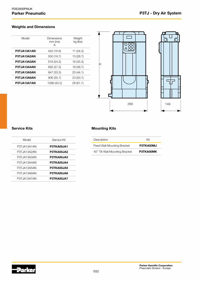
692
Parker Hannifin CorporationPneumatic Division - Europe
PDE2600PNUK
Parker Pneumatic
Weights and Dimensions
Model Service Kit
P3TJA13A1AN P3TKA00JA1
P3TJA13A2AN P3TKA00JA2
P3TJA13A3AN P3TKA00JA3
P3TJA13A4AN P3TKA00JA4
P3TJA13A5AN P3TKA00JA5
P3TJA13A6AN P3TKA00JA6
P3TJA13A7AN P3TKA00JA7
Service Kits
Description Kit
Fixed Wall Mounting Bracket P3TKA00MJ
45O Tilt Wall Mounting Bracket P3TKA00MK
Mounting Kits
A289 149
Model Dimensions Weight mm (ins) kg (lbs) A
P3TJA13A1AN 422 (16.6) 11 (24.2)
P3TJA13A2AN 500 (19.7) 13 (28.7)
P3TJA13A3AN 616 (24.2) 16 (35.3)
P3TJA13A4AN 692 (27.2) 18 (39.7)
P3TJA13A5AN 847 (33.3) 20 (44.1)
P3TJA13A6AN 906 (35.7) 23 (50.7)
P3TJA13A7AN 1098 (43.2) 28 (61.7)
P3TJ - Dry Air System
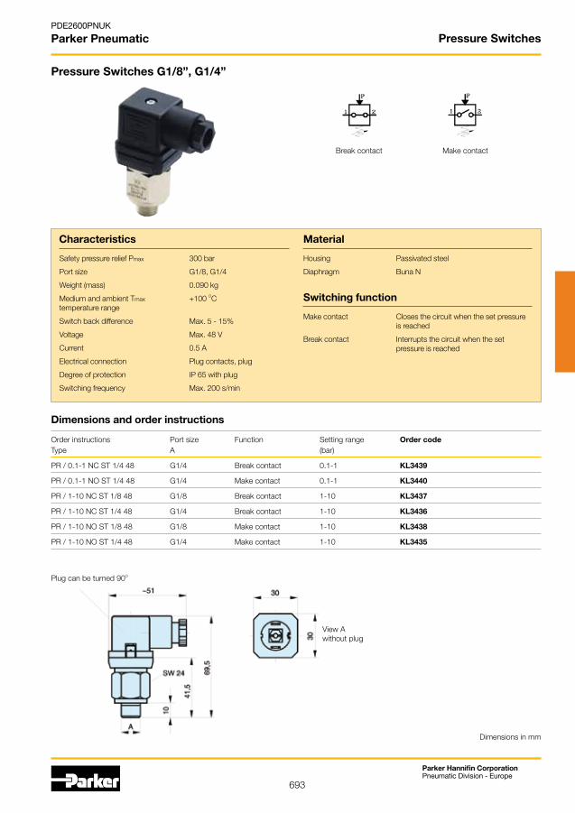
693
Parker Hannifin CorporationPneumatic Division - Europe
PDE2600PNUK
Parker Pneumatic Pressure Switches
Orderinstructions Portsize Function Settingrange Order code Type A (bar)
PR / 0.1-1 NC ST 1/4 48 G1/4 Break contact 0.1-1 KL3439
PR/0.1-1NOST1/448 G1/4 Makecontact 0.1-1 KL3440
PR / 1-10 NC ST 1/8 48 G1/8 Break contact 1-10 KL3437
PR / 1-10 NC ST 1/4 48 G1/4 Break contact 1-10 KL3436
PR/1-10NOST1/848 G1/8 Makecontact 1-10 KL3438
PR/1-10NOST1/448 G1/4 Makecontact 1-10 KL3435
Dimensions and order instructions
Characteristics
Safety pressure relief Pmax 300 bar
Port size G1/8, G1/4
Weight (mass) 0.090 kg
Medium and ambient Tmax +100 OC temperature range
Switch back difference Max. 5 - 15%
Voltage Max. 48 V
Current 0.5 A
Electrical connection Plug contacts, plug
Degree of protection IP 65 with plug
Switching frequency Max. 200 s/min
Pressure Switches G1/8”, G1/4”
Material
Housing Passivatedsteel
Diaphragm Buna N
Switching function
Make contact Closes the circuit when the set pressure is reached
Break contact Interrupts the circuit when the set pressure is reached
Dimensions in mm
Break contact Make contact
Plug can be turned 90O
View Awithout plug

694
Parker Hannifin CorporationPneumatic Division - Europe
PDE2600PNUK
Parker Pneumatic Pressure Switches
Orderinstructions Portsize Function Settingrange Order code Type A (bar)
PR/0.2-1NOSR1/448 G1/4 Makecontact 0.2-1 KL3445
PR / 0.1-1 NC SR 1/4 48 G1/4 Break contact 0.1-1 KL3454
PR/0.1-1NOSR1/448 G1/4 Makecontact 0.1-1 KL3455
PR / 1-10 NC SR 1/8 48 G1/8 Break contact 1-10 KL3452
PR / 1-10 NC SR 1/4 48 G1/4 Break contact 1-10 KL3451
PR/1-10NOSR1/848 G1/8 Makecontact 1-10 KL3453
PR/1-10NOSR1/448 G1/4 Makecontact 1-10 KL3450
Dimensions and order instructions
Characteristics
Safety pressure relief Pmax 300 bar
Port size G1/8, G1/4
Weight (mass) 0.075 kg
Medium and ambient Tmax +100 OC temperature range
Switch back difference Max. 5 - 15%
Voltage Max. 48 V
Current 0.5 A
Electrical connection Flat pin plug. protective cap
Degree of protection IP 65 with protective cap
Switching frequency 200 s/min
Pressure Switches G1/8”, G1/4”
Material
Housing Passivatedsteel
Diaphragm Buna N
Switching function
Make contact Closes the circuit when the set pressure is reached
Break contact Interrupts the circuit when the set pressure is reached
Break contact Make contact
Dimensions in mm
View Awithout protective cap
Protective cap can be turned 6 x 60O

695
Parker Hannifin CorporationPneumatic Division - Europe
PDE2600PNUK
Parker Pneumatic Pressure Switches
Characteristics
Type - thread version G1/4-0I* G1/4-2I G1/4-8I G1/4-16I
Type - flange version G1/4-0P* G1/4-2P G1/4-8P G1/4-16P
Setting range Pmin/max (bar) -1 to 0 0.2-2 0.5-8 1-16
Safety pressure relief Pmax 80 80 80 80
Port size Type I: G1/4 internal thread, Type P: flange
Mounting 2 through holes Ø 5.2
Installation In any position
Weight (mass) 0.275 kg
Medium Filtered compressed air (10μm), lubricated or unlubricated
Medium and ambient Tmin -10 OC
temperature range Tmax +80 OC
Consistency ±2 in relation to end-of-range value
Hysteresis,vaccumversion <15%
Vibration resistance 10 g(10...2000Hz)
Shock resistance 30 g
Voltage Max. 250 V
Pressure Switches G1/8”, G1/4”Series G1/4-..I / ..P
• Suitedforintrinsicallysafeoperation
• Especiallycompactdesign
• Highswitchingfrequency
• Attractivedesign
• Shockproofupto30g
Voltage type AC and DC
Operatingcurrentand AC12toVDE06604Aat250VAC AC14 to VDE0660 1A at 250 VAC DC12 to VDE0660 3A at 28 VDC DC13 to VDE0660 1A at 28 VDC
CE marking To EC Directive 73/23/EWG
Electrical connection Plug to DIN EN 175301-803, Form A, ISO4400orM12x1-4-pin
Degree of protection IP65
Switching element Pole changing switch with catch spring as switching element, with self-cleaning contacts
Switching frequency Max. 200 s/min
Material
Housing Specialaluminiumdiecasting, powder coated
Diaphragm, seals Buna N
* for vacuum operation
Range selection:Selection is optimal when the switching points are in the middle of the switching range.
Electrical connection:Wiring according to VDE regulations.Tightening torque for plug: 0.7 ± 0.1 NmOutdooruseonlywithsufficientpretectionagainstcriticalenvironmental conditions (e.g. aggressive atmosphere, salty environments, high temperature changes).
Selection and Mounting:
Switch back difference
Pin 1 - 3:Rising pressure makes contact.
Pin 1 - 2:Rising pressure breaks contact.
Delivery includes:The flange version (surface roughness of flange surface 12μm) is suppliedwithanO-ring5x1.5mmand2screws5x35DIN912.Minimum thread length to be used: 4mm.
Max. diameter of the pressure opening 3mm.
Switching point
Diff
eren
tial p
ress
ure
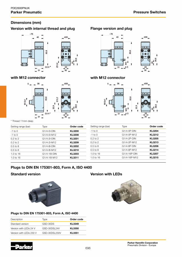
696
Parker Hannifin CorporationPneumatic Division - Europe
PDE2600PNUK
Parker Pneumatic Pressure Switches
Version with internal thread and plug
Dimensions (mm)
with M12 connector
* Thread 11mm deep
Setting range (bar) Type Order code
-1 to 0 G1/4-0I-DIN KL3200
-1 to 0 G1/4-0I-M12 KL3208
0.2 to 2 G1/4-2I-DIN KL3201
0.2 to 2 G1/4-2I-M12 KL3209
0.5 to 8 G1/4-8I-DIN KL3202
0.5 to 8 G1/4-8I-M12 KL3210
1.0 to 16 G1/4-16I-DIN KL3203
1.0 to 16 G1/4-16I-M12 KL3211
Flange version and plug
with M12 connector
Setting range (bar) Type Order code
-1 to 0 G1/4-0P-DIN KL3204
-1 to 0 G1/4-0P-M12 KL3212
0.2 to 2 G1/4-2P-DIN KL3205
0.2 to 2 G1/4-2P-M12 KL3213
0.5 to 8 G1/4-8P-DIN KL3206
0.5 to 8 G1/4-8P-M12 KL3214
1.0 to 16 G1/4-16P-DIN KL3207
1.0 to 16 G1/4-16P-M12 KL3215
Standard version
Plugs to DIN EN 175301-803, Form A, ISO 4400
Version with LEDs
Plugs to DIN EN 175301-803, Form A, ISO 4400
Description Type Order code
Standard version GSD-30DS KL3349
Version with LEDs 24 V GSD-30DSL24V KL3350
Version with LEDs 230 V GSD-30DSL230V KL3351
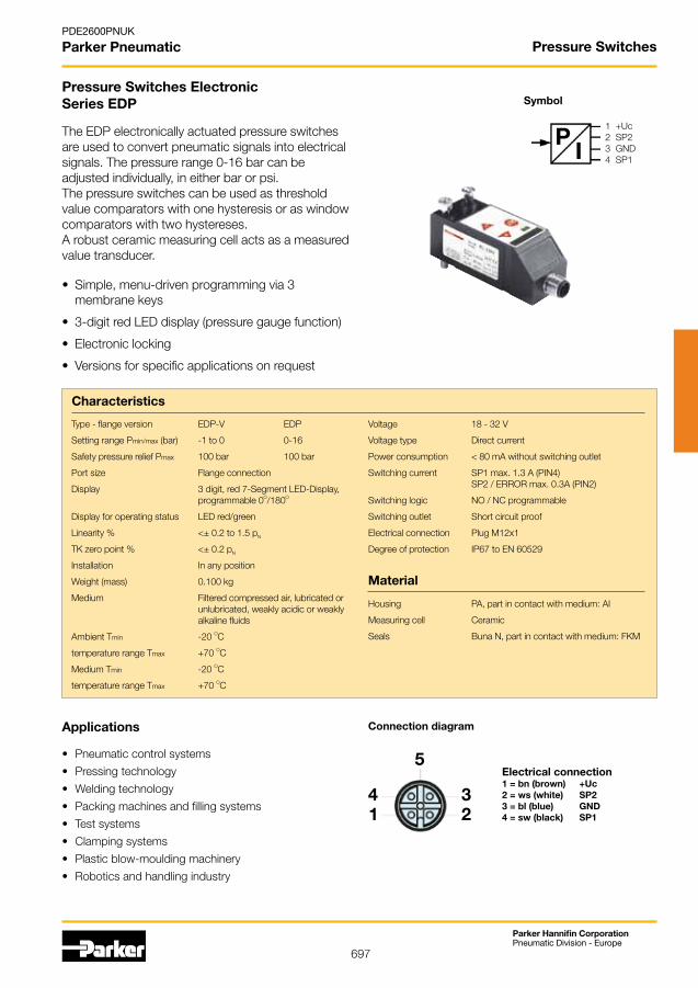
697
Parker Hannifin CorporationPneumatic Division - Europe
PDE2600PNUK
Parker Pneumatic Pressure Switches
Characteristics
Type - flange version EDP-V EDP
Setting range Pmin/max (bar) -1 to 0 0-16
Safety pressure relief Pmax 100 bar 100 bar
Port size Flange connection
Display 3 digit, red 7-Segment LED-Display, programmable 0O/180O
Display for operating status LED red/green
Linearity % <± 0.2 to 1.5 pN
TK zero point % <± 0.2 pN
Installation In any position
Weight (mass) 0.100 kg
Medium Filtered compressed air, lubricated or unlubricated, weakly acidic or weakly alkaline fluids
Ambient Tmin -20 OC
temperature range Tmax +70 OC
Medium Tmin -20 OC
temperature range Tmax +70 OC
Pressure Switches ElectronicSeries EDP
• Simple,menu-drivenprogrammingvia3 membrane keys
• 3-digitredLEDdisplay(pressuregaugefunction)
• Electroniclocking
• Versionsforspecificapplicationsonrequest
Voltage 18 - 32 V
Voltage type Direct current
Power consumption < 80 mA without switching outlet
Switching current SP1 max. 1.3 A (PIN4) SP2/ERRORmax.0.3A(PIN2)
Switchinglogic NO/NCprogrammable
Switching outlet Short circuit proof
Electrical connection Plug M12x1
Degree of protection IP67 to EN 60529
Material
Housing PA,partincontactwithmedium:AI
Measuring cell Ceramic
Seals Buna N, part in contact with medium: FKM
• Pneumaticcontrolsystems
• Pressingtechnology
• Weldingtechnology
• Packingmachinesandfillingsystems
• Testsystems
• Clampingsystems
• Plasticblow-mouldingmachinery
• Roboticsandhandlingindustry
Applications
Electrical connection1 = bn (brown) +Uc2 = ws (white) SP23 = bl (blue) GND4 = sw (black) SP1
Connection diagram
Symbol
1 +Uc2 SP23 GND4 SP1
The EDP electronically actuated pressure switches are used to convert pneumatic signals into electrical signals. The pressure range 0-16 bar can beadjustedindividually,ineitherbarorpsi.The pressure switches can be used as threshold value comparators with one hysteresis or as window comparators with two hystereses. A robust ceramic measuring cell acts as a measured value transducer.
PI
5
4 31 2

698
Parker Hannifin CorporationPneumatic Division - Europe
PDE2600PNUK
Parker Pneumatic Pressure Switches
Threshold value comparator with hysteresis
Threshold value comparator / window value comparator functions
Window comparator with 2 hystereses
TheillustrationsshowtheNO(normallyopen)presetting.For the NC (normally closed) presetting, the diagrams are horizontally mirror-imaged, so that the start value is at 1.
Setting range (bar) Type Order code
-1 to 1 EDP-V KL3385
0 to 16 EDP KL3384
Dimensions in mm.
Dimensions - Flange version with M12x1 connector
A
1
0
SP1 SP2 SP3 SP4
P
SP1 SP2
A
1
0P
5-pinconnectionM12x1
M12x1
O-ring5x1,5
30
10
30
20
7,5
M5
91,5
789,
5
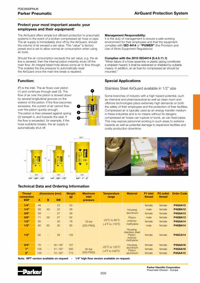
699
Parker Hannifin CorporationPneumatic Division - Europe
PDE2600PNUK
Parker Pneumatic AirGuard Protection System
The AirGuard offers simple but efficient protection to pneumatic systems in the event of a broken compressed-air hose or pipe. The air supply is immediately shut off by the AirGuard, should the volume of air exceed a set value. This “value” is factory preset and is set to allow normal air consumption when using air tools.
Management Responsibility:It is the duty of management to ensure a safe workingenvironment for their employees and that the equipmentcomplies with ISO 4414 or “PUWER” (the Provision andUse of Work Equipment Regulations)
(P) is the inlet. The air flows over piston (1) and continues through seat (3). The flow of air over the piston is slowed down by several longitudinal grooves on the exterior of the piston. If the flow becomes excessive, the current of air cannot flow over the piston quickly enough. The piston is then pressed against spring (2) beneath it, and towards the seat. If the flow is exceeded, for example, if the hose suddenly breaks, the air supply is automatically shut off.
Function:
3
2
1
PStainless Steel AirGuard available in 1/2” size
Special Applications
Some branches of industry with a high hazard potential, suchas chemical and pharmaceutical as well as clean room andoffshore technologies place extremely high demands on both the safety of their employees and the protection of their facilities. Compressed air is typically used as an energy transfer mediumin these industries and is no means without its dangers: compressed air hoses can rupture or burst, as can fixed pipes. This may expose personnel working in such areas to extreme hazards as well as potential damage to expensive facilities and costly production downtime.
Protect your most important assets: your employees and their equipment!
Technical Data and Ordering Information
Housing: aluminium Piston: aluminium
-20OC to 120OC
(-4OF to 248OF) 35 bar (500 PSIG)
3/4” 76 - 30 / 36* 107 female female P4GAA16
1” 100 - 41 / 50* 300 female female P4GAA18
2” 130 - 70 / 80* 775 female female P4GAA1C
Housing: stainless steel Piston: polyoxy methylene
Housing: aluminium
Piston: polyoxy- methylene 18 bar
(255 PSIG)
-20OC to 80OC
(-4OF to 176OF)
Thread dimensions (mm) Weight Maximum Temperature Material P1 inlet P2 outlet Order Code connection (g) inlet range thread thread BSP A B SW pressure
1/4” 48 - 22 30 female female P4GAA12
1/4” 58 49 22 36 male female P4GBA12
3/8” 59 - 27 58 female female P4GAA13
3/8” 71 59 27 62 male female P4GBA13
1/2” 65 - 30 78 female female P4GAA14
1/2” 80 65 30 85 male female P4GBA14
1/2” 62 - 28 132 female female P4GCA14
Note: NPT version available on request - 1/4” high flow version available on request.
Should the air consumption exceeds the set value, e.g. the air line is severed, then the internal piston instantly shuts off the main flow. An integral bleed hole allows some air to flow though. This enables the line pressure to automatically resetthe AirGuard once the main line break is repaired.
A
SW
SW *
A
B
SW
A
SW
1/4” - 3/8” - 1/2” 1/4” - 3/8” - 1/2” 3/4” - 1” - 2”
Complies with the 2010 ISO4414 (5.4.5.11.1)“When failure of a hose assembly or plastic piping constitutes a whiplash hazard, it shall be restrained or shielded by suitable means. In addition, an air fuse for compressed air should be mounted.”
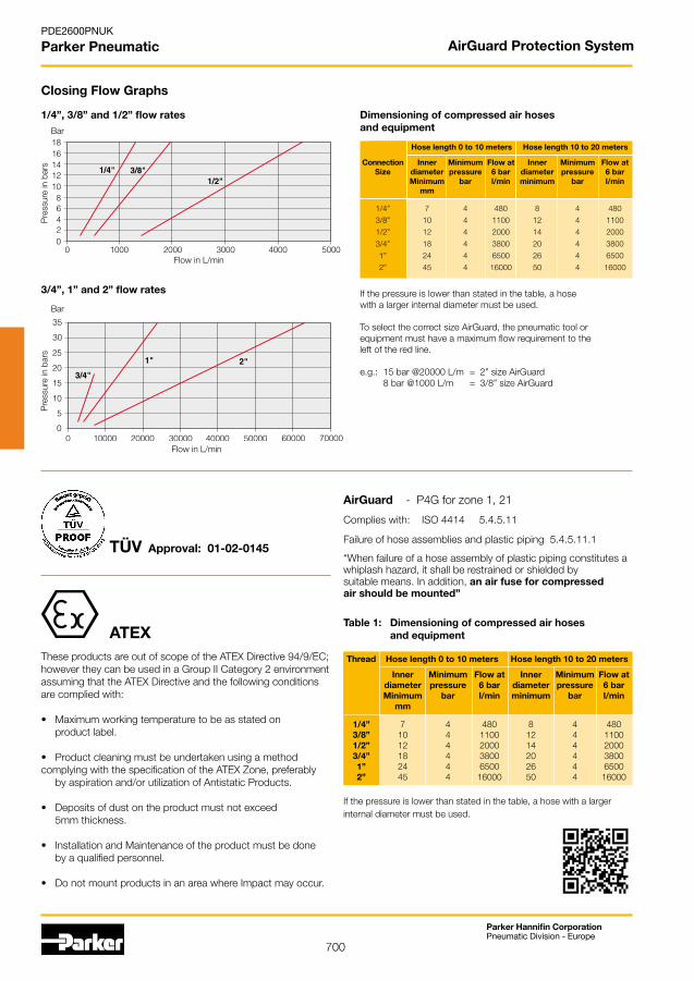
700
Parker Hannifin CorporationPneumatic Division - Europe
PDE2600PNUK
Parker Pneumatic AirGuard Protection System
Dimensioning of compressed air hoses and equipment
Hose length 0 to 10 meters Hose length 10 to 20 meters
Connection Inner Minimum Flow at Inner Minimum Flow at Size diameter pressure 6 bar diameter pressure 6 bar Minimum bar l/min minimum bar l/min mm
1/4” 7 4 480 8 4 480
3/8” 10 4 1100 12 4 1100
1/2” 12 4 2000 14 4 2000
3/4” 18 4 3800 20 4 3800
1” 24 4 6500 26 4 6500
2” 45 4 16000 50 4 16000
If the pressure is lower than stated in the table, a hosewith a larger internal diameter must be used.
To select the correct size AirGuard, the pneumatic tool orequipment must have a maximum flow requirement to theleft of the red line.
e.g.: 15 bar @20000 L/m = 2” size AirGuard 8 bar @1000 L/m = 3/8” size AirGuard
Pre
ssur
e in
bar
s
Bar
Flow in L/min
3/4”, 1” and 2” flow rates
1/4”, 3/8” and 1/2” flow rates
Pre
ssur
e in
bar
s
Bar
Closing Flow Graphs
Flow in L/min
These products are out of scope of the ATEX Directive 94/9/EC;however they can be used in a Group II Category 2 environmentassuming that the ATEX Directive and the following conditions are complied with: • Maximumworkingtemperaturetobeasstatedon product label.
• Productcleaningmustbeundertakenusingamethodcomplying with the specification of the ATEX Zone, preferably by aspiration and/or utilization of Antistatic Products.
• Depositsofdustontheproductmustnotexceed 5mm thickness.
• InstallationandMaintenanceoftheproductmustbedone by a qualified personnel.
• DonotmountproductsinanareawhereImpactmayoccur.
TÜV Approval: 01-02-0145
Table 1: Dimensioning of compressed air hoses and equipment
Thread Hose length 0 to 10 meters Hose length 10 to 20 meters
Inner Minimum Flow at Inner Minimum Flow at diameter pressure 6 bar diameter pressure 6 bar Minimum bar l/min minimum bar l/min mm
1/4” 7 4 480 8 4 480 3/8” 10 4 1100 12 4 1100 1/2” 12 4 2000 14 4 2000 3/4” 18 4 3800 20 4 3800 1” 24 4 6500 26 4 6500 2” 45 4 16000 50 4 16000
If the pressure is lower than stated in the table, a hose with a larger internal diameter must be used.
ATEX
AirGuard - P4G for zone 1, 21
Complieswith:ISO44145.4.5.11
Failure of hose assemblies and plastic piping 5.4.5.11.1
“When failure of a hose assembly of plastic piping constitutes a whiplash hazard, it shall be restrained or shielded bysuitable means. In addition, an air fuse for compressedair should be mounted”
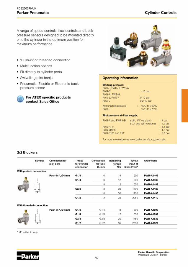
701
Parker Hannifin CorporationPneumatic Division - Europe
PDE2600PNUK
Parker Pneumatic
Operating information
• "Push-in"orthreadedconnection
• Multifunctionoptions
• Fitdirectlytocylinderports
• Swivellingpilotbanjo
• Pneumatic,ElectricorElectronicback pressure sensor
2/2 Blockers
Symbol Connection for Thread Connection Tightening Qmax Order code pilot port for cylinder for tube torque input at connection Ø, mm Nm 6 bar, l/min*
With push-in connection
Push-in *, Ø4 mm G1/8 6 8 500 PWB-A1468
G1/4 6 12 600 PWB-A1469
8 12 650 PWB-A1489
G3/8 8 30 1600 PWB-A1483
10 30 1750 PWB-A1493
G1/2 12 35 2050 PWB-A1412
With threaded connection
Push-in *, Ø4 mm G1/8 G1/4 8 500 PWB-A1898
G1/4 G1/4 12 650 PWB-A1899
G3/8 G3/8 30 1750 PWB-A1833
G1/2 G1/2 35 2050 PWB-A1822
Working pressure; PWR-L,PWR-H,PWR-A,PWR-B 1-10 barPWB-A, PWS-M, PWS-E, PWS-P 0-10 bar PWA-L 0,2-10 bar
Working temperature : -15°C to +60°CPWR-L -15°C to +70°C
Pilot pressure at 6 bar supply;
PWB-AandPWR-HB (1/8",1/4"versions) : 4bar (1/2"and3/8"versions) : 2,9barPWS-P111 : 4,4 barPWS-M1012 : 1,5 barPWS-E101 and E111 : 0,7 bar
* M5 without banjo
A range of speed controls, flow controls and back pressure sensors designed to be mounted directly onto the cylinder in the optimum position for maximum performance.
Cylinder Controls
For ATEX specific productscontact Sales Office
For more information see www.parker.com/euro_pneumatic
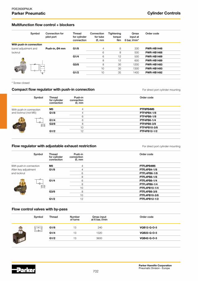
702
Parker Hannifin CorporationPneumatic Division - Europe
PDE2600PNUK
Parker Pneumatic
Multifunction flow control + blockers
Symbol Connection for Thread Connection Tightening Qmax Order code pilot port for cylinder for tube torque input at connection Ø, mm Nm 6 bar, l/min*
With push-in connection
barrel adjustment and Push-in, Ø4 mm G1/8 4 8 330 PWR-HB1448
locknut 6 8 500 PWR-HB1468
G1/4 6 12 500 PWR-HB1469
8 12 600 PWR-HB1489
G3/8 8 30 1200 PWR-HB1483
10 30 1300 PWR-HB1493
G1/2 10 35 1400 PWR-HB1492
Symbol Thread Push-in Order code for cylinder connection connection Ø, mm
M5 4 PTF8PB4M5 G1/8 4 PTF4PB4-1/8 6 PTF4PB6-1/8 G1/4 6 PTF4PB6-1/4 G3/8 8 PTF4PB8-3/8 10 PTF4PB10-3/8 G1/2 12 PTF4PB12-1/2
Compact flow regulator with push-in connection For direct port cylinder mounting
Symbol Thread Push-in Order code for cylinder connection connection Ø, mm
With push-in connection M5 4 PTFL8PB4M5Allen key adjustment G1/8 4 PTFL4PB4-1/8and locknut 6 PTFL4PB6-1/8 8 PTFL4PB8-1/8 G1/4 6 PTFL4PB6-1/4 8 PTFL4PB8-1/4 10 PTFL4PB10-1/4 G3/8 8 PTFL4PB8-3/8 10 PTFL4PB10-3/8 G1/2 12 PTFL4PB12-1/2
Flow regulator with adjustable exhaust restriction For direct port cylinder mounting
With push-in connectionand locknut (not M5)
Symbol Thread Number Qmax input Order code of turns at 6 bar, l/min
G1/8 13 240 VQB12-Q-O-5
G1/4 13 1320 VQB22-Q-O-5
G1/2 13 3600 VQB42-Q-O-5
Flow control valves with by-pass
* Screw closed
Cylinder Controls
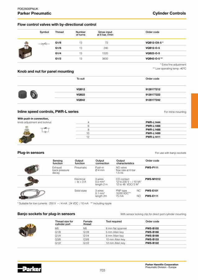
703
Parker Hannifin CorporationPneumatic Division - Europe
PDE2600PNUK
Parker Pneumatic
With push-in connection,knob adjustment and locknut 4 PWR-L1444 6 PWR-L1466 8 PWR-L1488 10 PWR-L1499 12 PWR-L1411
Exhaust Pneumatic Push-in NO valve PWS-P111 back pressure Ø 4 mm flow rate at 6 bar decay 1,5 I/s
Electrical 3 wires CO contact PWS-M1012 ~ le = 3 A 0,5 mm2 12 to 230 V ~ / 10 VA* length 2 m 12 to 48 VDC/ 5 W*
Solid state 3 wires PNP type NC PWS-E101 0,1 mm2 10/30 VDC** length 2m 75 mA NO PWS-E111
M5 M5 8 mm flat spanner PWS-B155 G1/8 G1/8 5 mm Allen key PWS-B188 G1/4 G1/4 8 mm Allen key PWS-B199 G3/8 G3/8 10 mm Allen key PWS-B133 G1/2 G1/2 12 mm Allen key PWS-B122
Symbol Thread Number Qmax input Order code of turns at 6 bar, l/min
G1/8 13 72 VQB12-OX-5 *
G1/8 13 240 VQB12-O-5
G1/4 13 1320 VQB22-O-5
G1/2 13 3600 VQB42-O-5 **
To suit Order code
VQB12 9128177212
VQB22 9128177222
VQB42 9128177242
Inline speed controls, PWR-L series For inline mounting
Plug-in sensors For use with banjo sockets
Sensing Output Output Output Order code function function connection characteristics
* Suitable for low currents : 250 V ~ / 4 mA ; 24 VDC / 10 mA ** Including ripple
Banjo sockets for plug-in sensors With sensor locking clip,for direct port cylinder mounting
Thread size for Female Tool required Order code cylinder port thread
Flow control valves with by-directional control
* Extra fine adjustment** Low operating temp -40oC
Knob and nut for panel mounting
Cylinder Controls
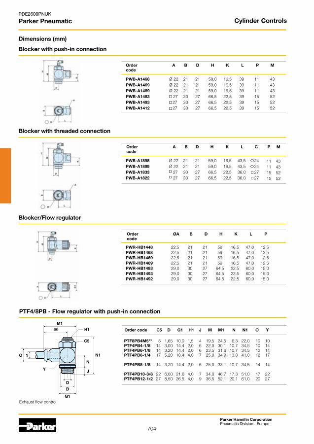
704
Parker Hannifin CorporationPneumatic Division - Europe
PDE2600PNUK
Parker Pneumatic
Dimensions (mm)
PTF4/8PB - Flow regulator with push-in connection
Order code C5 D G1 H1 J M M1 N N1 O Y
PTF8PB4M5** 8 1,65 10,0 1,5 4 19,5 24,5 6,3 22,0 10 10 PTF4PB4-1/8 14 3,00 14,4 2,0 6 22,0 30,1 10,7 34,5 10 14 PTF4PB6-1/8 14 3,20 14,4 2,0 6 23,5 31,6 10,7 34,5 12 14 PTF4PB6-1/4 17 5,20 18,4 4,0 7 25,0 34,9 13,8 41,0 12 17
PTF4PB8-1/8 14 3,20 14,4 2,0 6 25,0 33,1 10,7 34,5 14 14 PTF4PB10-3/8 22 6,00 21,6 4,0 7 34,0 46,7 17,3 51,0 17 22 PTF4PB12-1/2 27 8,50 26,5 4,0 9 36,5 52,1 20,1 61,0 20 27
Exhaust flow control
Order A B D H K L P M code
Order A B D H K L C P M code
Order ØA B D H K L P code
PWB-A1468 Ø 22 21 21 59,0 16,5 39 11 43 PWB-A1469 Ø 22 21 21 59,0 16,5 39 11 43 PWB-A1489 Ø 22 21 21 59,0 16,5 39 11 43 PWB-A1483 27 30 27 66,5 22,5 39 15 52 PWB-A1493 27 30 27 66,5 22,5 39 15 52 PWB-A1412 27 30 27 66,5 22,5 39 15 52
PWB-A1898 Ø 22 21 21 59,0 16,5 43,5 24 PWB-A1899 Ø 22 21 21 59,0 16,5 43,5 24 PWB-A1833 27 30 27 66,5 22,5 36,0 27 PWB-A1822 27 30 27 66,5 22,5 36,0 27
11 43 11 43 15 52 15 52
PWR-HB1448 22,5 21 21 59 16,5 47,0 12,5 PWR-HB1468 22,5 21 21 59 16,5 47,0 12,5 PWR-HB1469 22,5 21 21 59 16,5 47,0 12,5 PWR-HB1489 22,5 21 21 59 16,5 47,0 12,5 PWR-HB1483 29,0 30 27 64,5 22,5 60,0 15,0 PWR-HB1493 29,0 30 27 64,5 22,5 60,0 15,0 PWR-HB1492 29,0 30 27 64,5 22,5 60,0 15,0
Blocker with push-in connection
Blocker with threaded connection
Blocker/Flow regulator
Cylinder Controls

705
Parker Hannifin CorporationPneumatic Division - Europe
PDE2600PNUK
Parker Pneumatic
Dimensions (mm)
Speed Controls, PWR-L Series
Order code B F F1 e H+ H- H1 L Q PWR-L1444 12,0 14 * 6 25,5 21,5 6,5 39,0 10,5
PWR-L1466 17,0 19 * 7 32,5 27,5 7,5 54,0 17,0PWR-L1488 18,5 24 11 7 34,5 28,5 9,0 60,5 19,0PWR-L1499 24,0 30 14 7 38,5 29,5 11,5 76,0 25,0PWR-L1411 28,0 32 14 8 42,0 32,0 12,5 86,0 28,0
Order A B C D E F G H I code
VQB12-(Q)-OX-5 49 42 22 15 6,5 G1/8 5,8 24 M12x1 VQB12-(Q)-O-5 49 42 22 15 6,5 G1/8 5,8 24 M12x1 VQB22-(Q)-O-5 64 53 30 21 8,5 G1/4 7,0 32 M16x1 VQB42-(Q)-O-5 99 85 50 36 16,5 G1/2 7,0 50 M24x1,5
Order K L M O P R S T code
VQB12-(Q)-OX-5 1,2 32 15 - - - 13,5 8,8 VQB12-(Q)-O-5 1,2 32 15 - - - 13,5 8,8 VQB22-(Q)-O-5 1,2 42 20 6,0 M4 7 16,0 10,0 VQB42-(Q)-O-5 1,8 62 30 19,5 M4 7 20,5 15,2
Flow Control Valves
Order code C5 D G1 H1 H2 J M M1 N N1 O Y PTFL8PB4M5** 8 1,65 10,0 1,5 8 4 19,5 24,5 6,3 28,5 10 10 PTFL4PB4-1/8 14 3,00 14,4 2,0 7 6 22,0 30,1 10,7 43,7 10 14 PTFL4PB6-1/8 14 3,20 14,4 2,0 7 6 23,5 31,6 10,7 43,7 12 14 PTFL4PB6-1/4 17 5,20 18,4 4,0 11 7 25,0 34,9 13,8 51,8 12 17 PTFL4PB8-1/8 14 3,20 14,4 2,0 7 6 25,0 33,1 10,7 43,7 14 14 PTFL4PB8-1/4 17 5,20 18,4 4,0 11 7 28,5 38,3 13,8 51,8 14 17 PTFL4PB8-3/8 22 6,00 21,6 4,0 11 7 29,5 42,2 17,3 63,7 14 22 PTFL4PB10-3/8 22 6,00 21,6 4,0 11 7 34,0 46,7 17,3 63,7 17 22 PTFL4PB12-1/2 27 8,50 26,5 4,0 14 9 36,5 52.,1 20,1 76,1 20 27
PTFL4/8PB - Flow regulator with push-in connection
Exhaust flow control
Order C B H K L code
PWS-B155 8 11 16,5 10 17 PWS-B188 5 16 20,0 10 20 PWS-B199 8 21 20,0 10 22 PWS-B133 10 28 22,0 12 25 PWS-B122 12 33 26,0 14 26
Back Pressure Sensors - Modular
Cylinder Controls
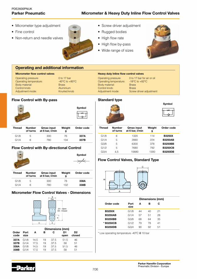
706
Parker Hannifin CorporationPneumatic Division - Europe
PDE2600PNUK
Parker Pneumatic
• Micrometertypeadjustment
• Finecontrol
• Non-returnandneedlevalves
Order Port A B C D1 D2 code size open closed
337A G1/8 14,5 19 37.5 51.5 46 337B G1/4 17,5 19 37.5 58 51 338A G1/8 14,5 19 37.5 51.5 46 338B G1/4 17,5 19 37.5 58 51
Micrometer Flow Control Valves - Dimensions
Flow Control with By-pass
Symbol
Flow Control with By-directional Control
Symbol
Operating and additional information
Operating pressure: 0 to 17 bar Operating temperature: -40OC to +80OCBody material: BrassControl knob: AluminiumAdjustment mode: Knurled knob
Thread Number Qmax input Weight Order code of turns at 6 bar, l/min g
G1/8 5 300 76 337A
G1/4 6 780 134 337B
• Screwdriveradjustment
• Ruggedbodies
• Highflowrate
• Highflowby-pass
• Widerangeofsizes
Operating pressure: 0 to 17 bar for air or oilOperating temperature: -18OC to +82OCBody material: BrassControl knob: BrassAdjustment mode: Screw driver adjustment
Symbol
Flow Control Valves, Standard Type
Order code Port A B C size
B3250X G1/8 44 40 21 B3250AB G1/4 57 51 28 B3250BB G3/8 68 64 35 * B3250CB G1/2 79 78 41 B3250DB G3/4 90 92 51
Thread Number Qmax input Weight Order code of turns at 6 bar, l/min g
G1/8 5 300 78 338A
G1/4 6 780 132 338B
Standard type
Thread Number Qmax input Weight Order code of turns at 6 bar, l/min g
G1/8 6 1320 114 B3250X
G1/4 5 2880 224 B3250AB
G3/8 5 6300 378 B3250BB
G1/2 5 7680 792 B3250CB
G3/4 4,5 10680 1300 B3250DB
Micrometer flow control valves Heavy duty Inline flow control valves
Dimensions (mm)
Dimensions (mm)
Micrometer & Heavy Duty Inline Flow Control Valves
* Low operating temperature -40oC @ 10 bar
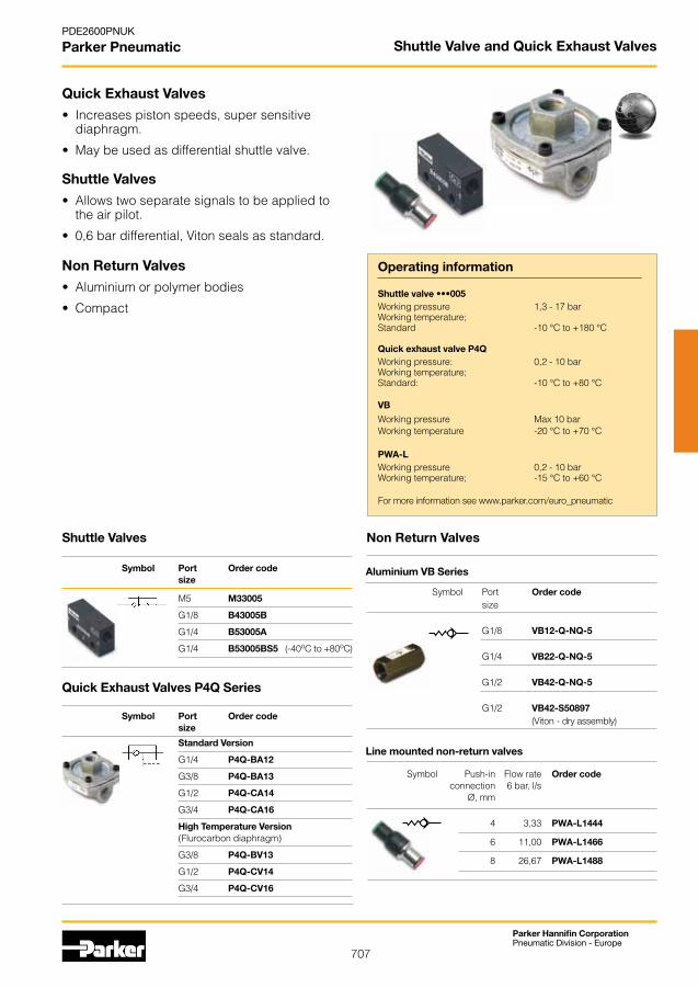
707
Parker Hannifin CorporationPneumatic Division - Europe
PDE2600PNUK
Parker Pneumatic
Aluminium VB Series
Symbol Port Order code size G1/8 VB12-Q-NQ-5 G1/4 VB22-Q-NQ-5 G1/2 VB42-Q-NQ-5 G1/2 VB42-S50897 (Viton - dry assembly)
Line mounted non-return valves
Symbol Push-in Flow rate Order code connection 6 bar, l/s Ø, mm
4 3,33 PWA-L1444
6 11,00 PWA-L1466
8 26,67 PWA-L1488
Shuttle Valves
Symbol Port Order code size
M5 M33005
G1/8 B43005B
G1/4 B53005A
G1/4 B53005BS5 (-40oC to +80oC)
Symbol Port Order code size
Standard Version
G1/4 P4Q-BA12
G3/8 P4Q-BA13
G1/2 P4Q-CA14
G3/4 P4Q-CA16
High Temperature Version (Flurocarbon diaphragm)
G3/8 P4Q-BV13
G1/2 P4Q-CV14
G3/4 P4Q-CV16
Operating information
Shuttle valve •••005Working pressure 1,3 - 17 barWorking temperature;Standard -10 °C to +180 °C
Quick exhaust valve P4QWorking pressure: 0,2 - 10 barWorking temperature;Standard: -10 °C to +80 °C
VB
Working pressure Max 10 barWorking temperature -20 °C to +70 °C
PWA-LWorking pressure 0,2 - 10 barWorking temperature; -15 °C to +60 °C
Non Return Valves
Quick Exhaust Valves P4Q Series
Quick Exhaust Valves
• Increases piston speeds, super sensitive diaphragm.
• May be used as differential shuttle valve.
Shuttle Valves
• Allows two separate signals to be applied to the air pilot.
• 0,6 bar differential, Viton seals as standard.
Non Return Valves
• Aluminium or polymer bodies
• Compact
Shuttle Valve and Quick Exhaust Valves
For more information see www.parker.com/euro_pneumatic

708
Parker Hannifin CorporationPneumatic Division - Europe
PDE2600PNUK
Parker Pneumatic
Dimensions (mm)
Order Port A B C code Size
P4Q-B*12 G1/4 52 25 62 P4Q-B*13 G3/8 52 25 62 P4Q-B*14 G1/2 73 38 86 P4Q-B*16 G3/4 73 38 86
Quick Exhaust Valves
Shuttle Valves
Order Port A B C D E F G H code Size
M33005 M5 27,5 24 15 16,0 15 6 6,3 3,2 B43005B G1/8 44,0 24 15 16,0 25 6 9,5 4,5 B53005A G1/4 52,0 30 22 20,5 35 10 8,5 5,5
Non Return Valves - VB - Female
Order F L N code
VB12-Q-NQ-5 G1/8 31 14 VQB22-Q-NQ-5 G1/4 40 17 VB42-Q-NQ-5 G1/2 59 27
Non Return Valves - Push-in
Order ØH L code
PWA-L1444 11,0 43,0 PWA-L1466 13,0 49,5 PWA-L1488 13,5 55,0
Shuttle Valve and Quick Exhaust Valves
* Dimensions as B53005BS5
*
* Dimensions as VB42 / S50897
*

709
Parker Hannifin CorporationPneumatic Division - Europe
PDE2600PNUK
Parker Pneumatic
• Allplasticultralightweightversions
• Sinteredmetal
• Allmetalversionsforheavydutyapplications
• Versionswithpush-inconnections
• Highnoiselevelreduction
• Lowbackpressuregeneration
Plastic Working temperature: -100C to +800C Efficiency 92% Metal Working temperature: -100C to +740C Working pressure up to 17 bar
P6M-P Plastic Series
Port Ø Weight Order code thread A B C g
M5 23 6,5 4 0,01 P6M-PAC5
G1/8 29 14 6 0,02 P6M-PAB1
G1/4 34 17 6 0,04 P6M-PAB2
G3/8 60 25 9 0,06 P6M-PAB3
G1/2 64 25 11 0,10 P6M-PAB4
G3/4 140 38 14 0,50 P6M-PAB6
G1 160 48 20 0,62 P6M-PAB8
Push-in Series
Symbol
Symbol Port Height on Weight Order code mm Push-in g
4 20,0 0,040 PXC-X14
6 35,5 0,025 PZC-S1006
8 34,0 0,030 PZC-S1008
Operating and additional information
Dimensions (mm)
Exhaust Silencers
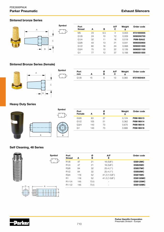
710
Parker Hannifin CorporationPneumatic Division - Europe
PDE2600PNUK
Parker Pneumatic
Port Ø Weight Order code Female A B g
G3/8 83 37 0,124 P6M-MA13
G1/2 105 51 0,362 P6M-MA14
G3/4 143 73 0,670 P6M-MA16
G1 143 73 0.666 P6M-MA18
Heavy Duty Series
Sintered bronze Series
Port A/F Weight Order code thread A B C g
M5 23 6,5 4 0,003 9721900005
G1/8 24 10 12 0,009 9090050700
G1/4 32 11 16 0,019 P6M-BAA2
G3/8 43 13 21 0,041 9090050900
G1/2 60 16 24 0,068 9090051000
G3/4 75 10 32 0,126 9090051100
G1 77 12 37 0,188 9090051500
Port Ø A/F Weight Order code mm A B C g
G1/8 15 8 13 0,060 9721900404
Sintered Bronze Series (female)
Self Cleaning, 48 Series
Symbol
Symbol
Symbol
Symbol
A
B
C
A
B
C
Port Ø A/F Order codethread A B E
R1/8 47 21 16 (5/8”) ESB12MC
R1/4 47 21 16 (5/8”) ESB25MC
R3/8 84 32 25.4 (1”) ESB37MC
R1/2 84 32 25.4 (1”) ESB50MC
R3/4 116 52 41.2 (1-5/8”) ESB75MC
R1 116 52 41.2 (1-5/8”) ESB100MC
R1-1/4 145 73.5 - ESB125MC
R1-1/2 145 73.5 - ESB150MCD A
B
Exhaust Silencers

711
Parker Hannifin CorporationPneumatic Division - Europe
PDE2600PNUK
Parker Pneumatic
• Metal,stainlesssteelorplasticversions
• Screwdriveradjustment
• Simplecontrolofcylinderspeeds
• Highnoiselevelreduction
Sintered Metal Series
Port Overall A/F Order code thread length
R1/8 29.5 9/16” 43006
R1/4 36.0 1/2” T53006
R3/8 38.0 11/16” T63006A
G1/2 45.0 7/8” B73006
Sintered Plastic Series
Port Ø Order code thread A B C
G1/8 23 16 7 9301050901
G1/4 32 23 9 9301050902
G3/8 40 30 10 9301050903
G1/2 50 38 12 9301050904
Sintered Stainless Steel Series
Port Overall Ø A/F Order code thread length
G1/8 33 16 13,0 9126900195
G1/4 36 20 17,0 9126900196
Restrictors - Silencers
Symbol
Symbol
Symbol
A
B
C
Exhaust Silencers
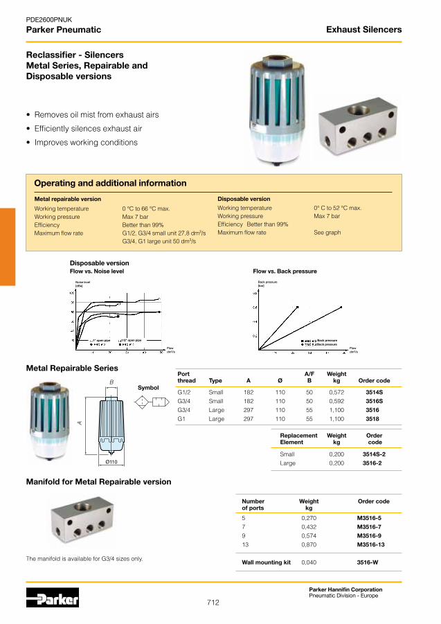
712
Parker Hannifin CorporationPneumatic Division - Europe
PDE2600PNUK
Parker Pneumatic
Reclassifier - SilencersMetal Series, Repairable andDisposable versions
• Removesoilmistfromexhaustairs
• Efficientlysilencesexhaustair
• Improvesworkingconditions
Metal Repairable SeriesPort A/F Weightthread Type A Ø B kg Order code
G1/2 Small 182 110 50 0,572 3514S G3/4 Small 182 110 50 0,592 3516S G3/4 Large 297 110 55 1,100 3516
G1 Large 297 110 55 1,100 3518
Metal repairable version
Working temperature 0 °C to 66 °C max.Working pressure Max 7 bar Efficiency Better than 99%Maximum flow rate G1/2, G3/4 small unit 27,8 dm3/s G3/4, G1 large unit 50 dm3/s
Disposable version
Working temperature 0° C to 52 °C max.Working pressure Max 7 barEfficiency Better than 99%Maximum flow rate See graph
Replacement Weight Order Element kg code Small 0,200 3514S-2 Large 0,200 3516-2
SymbolB
A
Disposable versionFlow vs. Noise level Flow vs. Back pressure
Noise level[dBa]
Flowdm3/s
1" open pipe 1/2" open pipe
Back pressure[bar]
Flowdm3/s
Back pressureBack pressure
Number Weight Order code of ports kg
5 0,270 M3516-5
7 0,432 M3516-7
9 0,574 M3516-9 13 0,870 M3516-13
Wall mounting kit 0,040 3516-W
Manifold for Metal Repairable version
The manifold is available for G3/4 sizes only.
Operating and additional information
Exhaust Silencers
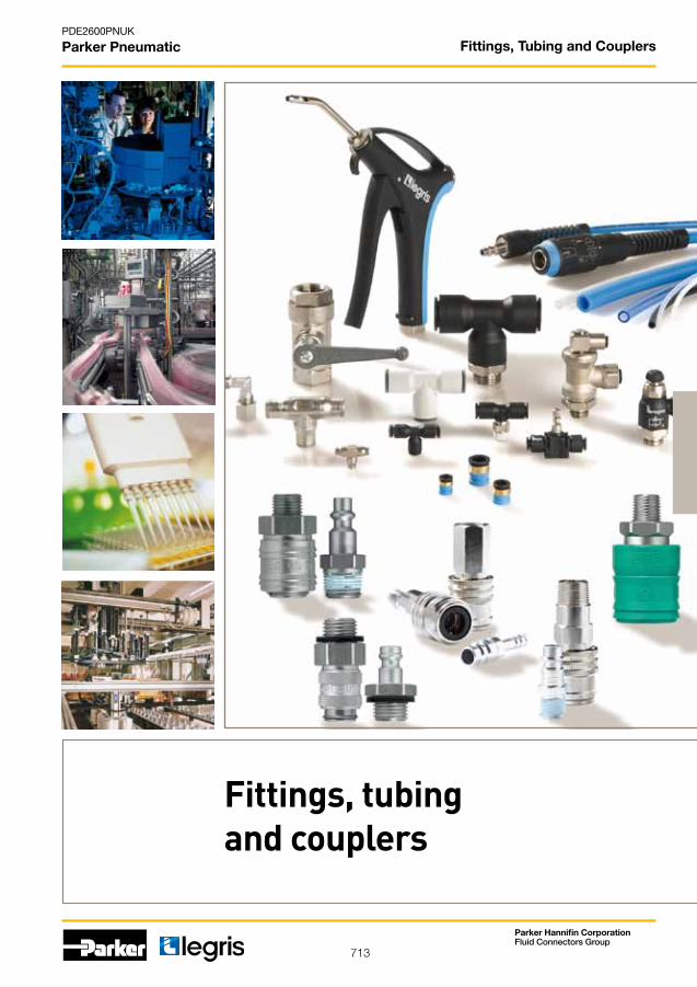
713
PDE2600PNUK
Parker Pneumatic
Parker Hannifin CorporationFluid Connectors Group
Fittings, tubingand couplers
Fittings, Tubing and Couplers
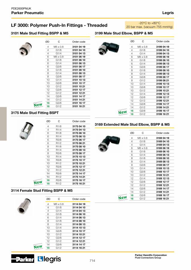
714
PDE2600PNUK
Parker Pneumatic
Parker Hannifin CorporationFluid Connectors Group
Legris
4 M5 x 0.8 3101 04 19 4 G1/8 3101 04 10 4 G1/4 3101 04 13 6 M5 x 0.8 3101 06 19 6 G1/8 3101 06 10 6 G1/4 3101 06 13 6 G3/8 3101 06 17 8 G1/8 3101 08 10 8 G1/4 3101 08 13 8 G3/8 3101 08 17 10 G1/4 3101 10 13 10 G3/8 3101 10 17 10 G1/2 3101 10 21 12 G3/8 3101 12 17 12 G1/2 3101 12 21 14 G3/8 3101 14 17 14 G1/2 3101 14 21 16 G3/8 3101 16 17 16 G1/2 3101 16 21
4 R1/8 3175 04 10 4 R1/4 3175 04 13 6 R1/8 3175 06 10 6 R1/4 3175 06 13 6 R3/8 3175 06 17 6 R1/2 3175 06 21 8 R1/8 3175 08 10 8 R1/4 3175 08 13 8 R3/8 3175 08 17 10 R1/4 3175 10 13 10 R3/8 3175 10 17 10 R1/2 3175 10 21 12 R3/8 3175 12 17 12 R1/2 3175 12 21 14 R3/8 3175 14 17 14 R1/2 3175 14 21 16 R3/8 3175 16 17 16 R1/2 3175 16 21
4 M5 x 0.8 3199 04 19 4 G1/8 3199 04 10 4 G1/4 3199 04 13 6 M5 x 0.8 3199 06 19 6 G1/8 3199 06 10 6 G1/4 3199 06 13 6 G3/8 3199 06 17 8 G1/8 3199 08 10 8 G1/4 3199 08 13 8 G3/8 3199 08 17 8 G1/2 3199 08 21 10 G1/4 3199 10 13 10 G3/8 3199 10 17 10 G1/2 3199 10 21 12 G1/4 3199 12 13 12 G3/8 3199 12 17 12 G1/2 3199 12 21 14 G3/8 3199 14 17 14 G1/2 3199 14 21 16 G3/8 3199 16 17 16 G1/2 3199 16 21
4 M5 x 0.8 3169 04 19 4 G1/8 3169 04 10 4 G1/4 3169 04 13 6 M5 x 0.8 3169 06 19 6 G1/8 3169 06 10 6 G1/4 3169 06 13 8 G1/8 3169 08 10 8 G1/4 3169 08 13 8 G3/8 3169 08 17 10 G1/4 3169 10 13 10 G3/8 3169 10 17 10 G1/2 3169 10 21 12 G1/4 3169 12 13 12 G3/8 3169 12 17 12 G1/2 3169 12 21 14 G3/8 3169 14 17 14 G1/2 3169 14 21 16 G3/8 3169 16 17 16 G1/2 3169 16 21
4 M5 x 0.8 3114 04 19 4 G1/8 3114 04 10 4 G1/4 3114 04 13 6 G1/8 3114 06 10 6 G1/4 3114 06 13 8 G1/8 3114 08 10 8 G1/4 3114 08 13 10 G1/4 3114 10 13 10 G3/8 3114 10 17 10 G1/2 3114 10 21 12 G3/8 3114 12 17 12 G1/2 3114 12 21 14 G3/8 3114 14 17 16 G1/2 3114 16 21
LF 3000: Polymer Push-In Fittings - Threaded
3101 Male Stud Fitting BSPP & M5
ØD C Order code
3175 Male Stud Fitting BSPT
ØD C Order code
3199 Male Stud Elbow, BSPP & M5
ØD C Order code
3169 Extended Male Stud Elbow, BSPP & M5
ØD C Order code
-20°C to +80°C20barmax.(vacuum755mmHg)
3114 Female Stud Fitting BSPP & M5
ØD C Order code
New
New
New
New
New
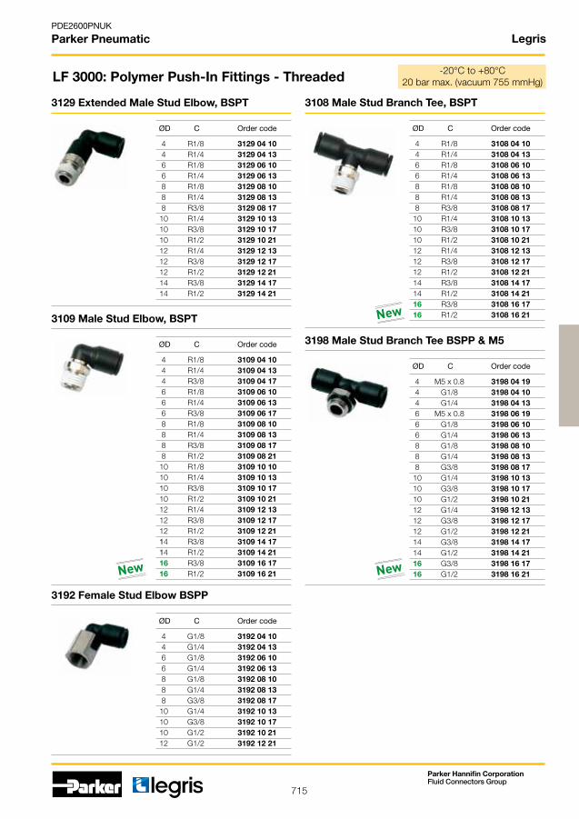
715
PDE2600PNUK
Parker Pneumatic
Parker Hannifin CorporationFluid Connectors Group
Legris
4 R1/8 3129 04 10 4 R1/4 3129 04 13 6 R1/8 3129 06 10 6 R1/4 3129 06 13 8 R1/8 3129 08 10 8 R1/4 3129 08 13 8 R3/8 3129 08 17 10 R1/4 3129 10 13 10 R3/8 3129 10 17 10 R1/2 3129 10 21 12 R1/4 3129 12 13 12 R3/8 3129 12 17 12 R1/2 3129 12 21 14 R3/8 3129 14 17 14 R1/2 3129 14 21
4 R1/8 3109 04 10 4 R1/4 3109 04 13 4 R3/8 3109 04 17 6 R1/8 3109 06 10 6 R1/4 3109 06 13 6 R3/8 3109 06 17 8 R1/8 3109 08 10 8 R1/4 3109 08 13 8 R3/8 3109 08 17 8 R1/2 3109 08 21 10 R1/8 3109 10 10 10 R1/4 3109 10 13 10 R3/8 3109 10 17 10 R1/2 3109 10 21 12 R1/4 3109 12 13 12 R3/8 3109 12 17 12 R1/2 3109 12 21 14 R3/8 3109 14 17 14 R1/2 3109 14 21 16 R3/8 3109 16 17 16 R1/2 3109 16 21
4 G1/8 3192 04 10 4 G1/4 3192 04 13 6 G1/8 3192 06 10 6 G1/4 3192 06 13 8 G1/8 3192 08 10 8 G1/4 3192 08 13 8 G3/8 3192 08 17 10 G1/4 3192 10 13 10 G3/8 3192 10 17 10 G1/2 3192 10 21 12 G1/2 3192 12 21
4 R1/8 3108 04 10 4 R1/4 3108 04 13 6 R1/8 3108 06 10 6 R1/4 3108 06 13 8 R1/8 3108 08 10 8 R1/4 3108 08 13 8 R3/8 3108 08 17 10 R1/4 3108 10 13 10 R3/8 3108 10 17 10 R1/2 3108 10 21 12 R1/4 3108 12 13 12 R3/8 3108 12 17 12 R1/2 3108 12 21 14 R3/8 3108 14 17 14 R1/2 3108 14 21 16 R3/8 3108 16 17 16 R1/2 3108 16 21
4 M5 x 0.8 3198 04 19 4 G1/8 3198 04 10 4 G1/4 3198 04 13 6 M5 x 0.8 3198 06 19 6 G1/8 3198 06 10 6 G1/4 3198 06 13 8 G1/8 3198 08 10 8 G1/4 3198 08 13 8 G3/8 3198 08 17 10 G1/4 3198 10 13 10 G3/8 3198 10 17 10 G1/2 3198 10 21 12 G1/4 3198 12 13 12 G3/8 3198 12 17 12 G1/2 3198 12 21 14 G3/8 3198 14 17 14 G1/2 3198 14 21 16 G3/8 3198 16 17 16 G1/2 3198 16 21
3129 Extended Male Stud Elbow, BSPT
ØD C Order code
3109 Male Stud Elbow, BSPT
ØD C Order code
LF 3000: Polymer Push-In Fittings - Threaded
3192 Female Stud Elbow BSPP
ØD C Order code
3108 Male Stud Branch Tee, BSPT
ØD C Order code
-20°C to +80°C 20barmax.(vacuum755mmHg)
3198 Male Stud Branch Tee BSPP & M5
New New
New
ØD C Order code

716
PDE2600PNUK
Parker Pneumatic
Parker Hannifin CorporationFluid Connectors Group
Legris
4 R1/8 3103 04 10 4 R1/4 3103 04 13 6 R1/8 3103 06 10 6 R1/4 3103 06 13 8 R1/8 3103 08 10 8 R1/4 3103 08 13 8 R3/8 3103 08 17 10 R1/4 3103 10 13 10 R3/8 3103 10 17 10 R1/2 3103 10 21 12 R1/4 3103 12 13 12 R3/8 3103 12 17 12 R1/2 3103 12 21 14 R3/8 3103 14 17 14 R1/2 3103 14 21 16 R3/8 3103 16 17 16 R1/2 3103 16 21
4 R1/8 3121 04 10 4 R1/4 3121 04 13 6 R1/8 3121 06 10 6 R1/4 3121 06 13 8 R1/8 3121 08 10 8 R1/4 3121 08 13 8 R3/8 3121 08 17 10 R1/4 3121 10 13 10 R3/8 3121 10 17 10 R1/2 3121 10 21 12 R3/8 3121 12 17 12 R1/2 3121 12 21 14 R1/2 3121 14 21
4 M5 x 0.8 3131 04 19 4 G1/8 3131 04 10 4 G1/4 3131 04 13 6 G1/8 3131 06 10 6 G1/4 3131 06 13 8 G1/8 3131 08 10 8 G1/4 3131 08 13 8 G3/8 3131 08 17 10 G1/4 3131 10 13 10 G3/8 3131 10 17 10 G1/2 3131 10 21 12 G3/8 3131 12 17 12 G1/2 3131 12 21 14 G3/8 3131 14 17 14 G1/2 3131 14 21
4 M5 x 0.8 3193 04 19 4 G1/8 3193 04 10 4 G1/4 3193 04 13 6 M5 x 0,8 3193 06 19 6 G1/8 3193 06 10 6 G1/4 3193 06 13 8 G1/8 3193 08 10 8 G1/4 3193 08 13 8 G3/8 3193 08 17 10 G1/4 3193 10 13 10 G3/8 3193 10 17 10 G1/2 3193 10 21 12 G1/4 3193 12 13 12 G3/8 3193 12 17 12 G1/2 3193 12 21 14 G3/8 3193 14 17 14 G1/2 3193 14 21 16 G3/8 3193 16 17 16 G1/2 3193 16 21
4 R1/8 3113 04 10 6 R1/8 3113 06 10 6 R1/4 3113 06 13 8 R1/8 3113 08 10 8 R1/4 3113 08 13 8 R3/8 3113 08 17 10 R1/4 3113 10 13 10 R3/8 3113 10 17 10 R1/2 3113 10 21 12 R1/4 3113 12 13 12 R3/8 3113 12 17 12 R1/2 3113 12 21
4 M5 x 0.8 3133 04 19 4 G1/8 3133 04 10 6 M5 x 0.8 3133 06 19 6 G1/8 3133 06 10 6 G1/4 3133 06 13 8 G1/8 3133 08 10 8 G1/4 3133 08 13 8 G3/8 3133 08 17 10 G1/4 3133 10 13 10 G3/8 3133 10 17 10 G1/2 3133 10 21 12 G1/4 3133 12 13 12 G3/8 3133 12 17 12 G1/2 3133 12 21
LF 3000: Polymer Push-In Fittings - Threaded
3103 Male Stud Run Tee, BSPT
ØD C Order code
3121 Male Standpipe BSPT
ØD C Order code
3131 Male Standpipe BSPP
ØD C Order code
3193 Male Stud Run Tee, BSPP & M5
ØD C Order code
-20°C to +80°C 20barmax.(vacuum755mmHg)
3113 45° Male Elbow, BSPT
ØD C Order code
3133 45° Male Elbow, BSPP & M5
ØD C Order code
New
New
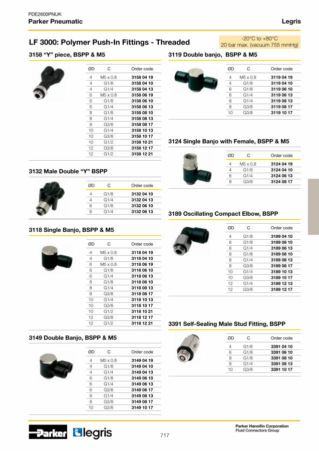
717
PDE2600PNUK
Parker Pneumatic
Parker Hannifin CorporationFluid Connectors Group
Legris
4 M5 x 0.8 3158 04 19 4 G1/8 3158 04 10 4 G1/4 3158 04 13 6 M5 x 0.8 3158 06 19 6 G1/8 3158 06 10 6 G1/4 3158 06 13 8 G1/8 3158 08 10 8 G1/4 3158 08 13 8 G3/8 3158 08 17 10 G1/4 3158 10 13 10 G3/8 3158 10 17 10 G1/2 3158 10 21 12 G3/8 3158 12 17 12 G1/2 3158 12 21
4 G1/8 3132 04 10 4 G1/4 3132 04 13 6 G1/8 3132 06 10 6 G1/4 3132 06 13
4 M5 x 0.8 3118 04 19 4 G1/8 3118 04 10 6 M5 x 0.8 3118 06 19 6 G1/8 3118 06 10 6 G1/4 3118 06 13 8 G1/8 3118 08 10 8 G1/4 3118 08 13 8 G3/8 3118 08 17 10 G1/4 3118 10 13 10 G3/8 3118 10 17 10 G1/2 3118 10 21 12 G3/8 3118 12 17 12 G1/2 3118 12 21
4 M5 x 0.8 3119 04 19 4 G1/8 3119 04 10 6 G1/8 3119 06 10 6 G1/4 3119 06 13 8 G1/4 3119 08 13 8 G3/8 3119 08 17 10 G3/8 3119 10 17
4 M5 x 0.8 3149 04 19 4 G1/8 3149 04 10 4 G1/4 3149 04 13 6 G1/8 3149 06 10 6 G1/4 3149 06 13 6 G3/8 3149 06 17 8 G1/4 3149 08 13 8 G3/8 3149 08 17 10 G3/8 3149 10 17
4 M5 x 0.8 3124 04 19 4 G1/8 3124 04 10 6 G1/4 3124 06 13 8 G3/8 3124 08 17
4 G1/8 3189 04 10 6 G1/8 3189 06 10 6 G1/4 3189 06 13 8 G1/8 3189 08 10 8 G1/4 3189 08 13 8 G3/8 3189 08 17 10 G1/4 3189 10 13 10 G3/8 3189 10 17 12 G1/4 3189 12 13 12 G3/8 3189 12 17
4 G1/8 3391 04 10 6 G1/8 3391 06 10 8 G1/8 3391 08 10 8 G1/4 3391 08 13 10 G3/8 3391 10 17
3158 “Y” piece, BSPP & M5
ØD C Order code
3132 Male Double “Y” BSPP
LF 3000: Polymer Push-In Fittings - Threaded
3118 Single Banjo, BSPP & M5
ØD C Order code
3119 Double banjo, BSPP & M5
ØD C Order code
3149 Double Banjo, BSPP & M5
ØD C Order code
3124 Single Banjo with Female, BSPP & M5
ØD C Order code
-20°C to +80°C20barmax.(vacuum755mmHg)
3189 Oscillating Compact Elbow, BSPP
ØD C Order code
3391 Self-Sealing Male Stud Fitting, BSPP
ØD C Order code
ØD C Order code
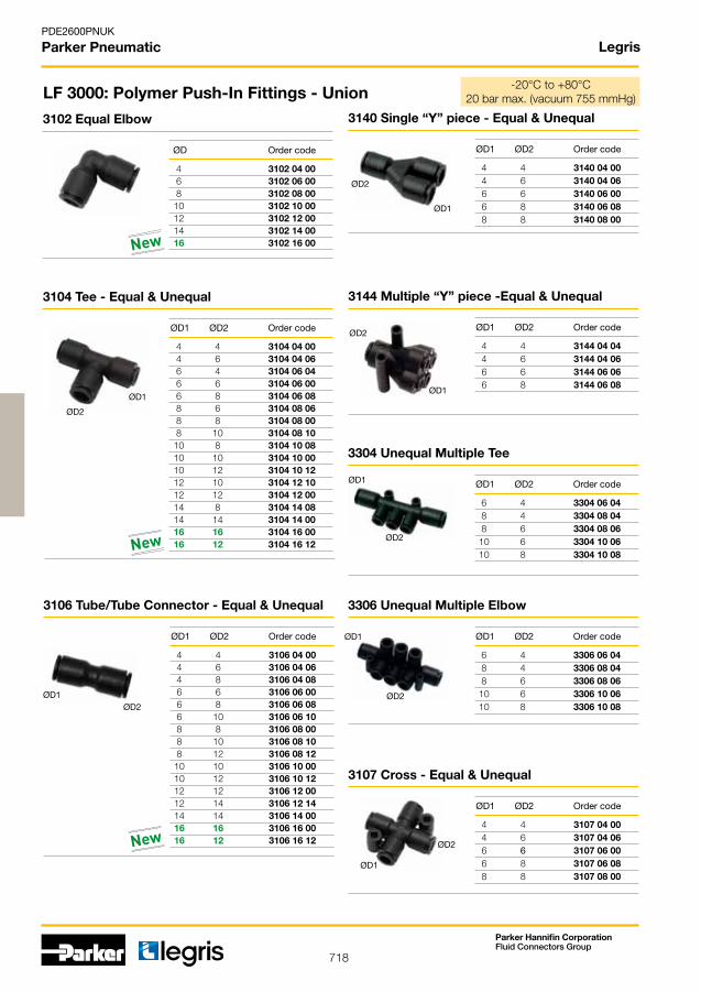
718
PDE2600PNUK
Parker Pneumatic
Parker Hannifin CorporationFluid Connectors Group
Legris
4 3102 04 00 6 3102 06 00 8 3102 08 00 10 3102 10 00 12 3102 12 00 14 3102 14 00 16 3102 16 00
4 4 3104 04 00 4 6 3104 04 06 6 4 3104 06 04 6 6 3104 06 00 6 8 3104 06 08 8 6 3104 08 06 8 8 3104 08 00 8 10 3104 08 10 10 8 3104 10 08 10 10 3104 10 00 10 12 3104 10 12 12 10 3104 12 10 12 12 3104 12 00 14 8 3104 14 08 14 14 3104 14 00 16 16 3104 16 00 16 12 3104 16 12
ØD1
ØD2
6 4 3304 06 04 8 4 3304 08 04 8 6 3304 08 06 10 6 3304 10 06 10 8 3304 10 08
6 4 3306 06 04 8 4 3306 08 04 8 6 3306 08 06 10 6 3306 10 06 10 8 3306 10 08
4 4 3107 04 00 4 6 3107 04 06 6 6 3107 06 00 6 8 3107 06 08 8 8 3107 08 00
4 4 3144 04 04 4 6 3144 04 06 6 6 3144 06 06 6 8 3144 06 08
ØD1
ØD1
ØD1
ØD1
ØD2
ØD2
ØD2
ØD2
4 4 3106 04 00 4 6 3106 04 06 4 8 3106 04 08 6 6 3106 06 00 6 8 3106 06 08 6 10 3106 06 10 8 8 3106 08 00 8 10 3106 08 10 8 12 3106 08 12 10 10 3106 10 00 10 12 3106 10 12 12 12 3106 12 00 12 14 3106 12 14 14 14 3106 14 00 16 16 3106 16 00 16 12 3106 16 12
ØD1 ØD2
4 4 3140 04 00 4 6 3140 04 06 6 6 3140 06 00 6 8 3140 06 08 8 8 3140 08 00
ØD1
ØD2
LF 3000: Polymer Push-In Fittings - Union
3102 Equal Elbow
ØD Order code
3104 Tee - Equal & Unequal
ØD1 ØD2 Order code
3304 Unequal Multiple Tee
ØD1 ØD2 Order code
3306 Unequal Multiple Elbow
ØD1 ØD2 Order code
3107 Cross - Equal & Unequal
ØD1 ØD2 Order code
3140 Single “Y” piece - Equal & Unequal
ØD1 ØD2 Order code
3144 Multiple “Y” piece -Equal & Unequal
ØD1 ØD2 Order code
-20°C to +80°C20barmax.(vacuum755mmHg)
3106 Tube/Tube Connector - Equal & Unequal
ØD1 ØD2 Order code
New
New
New
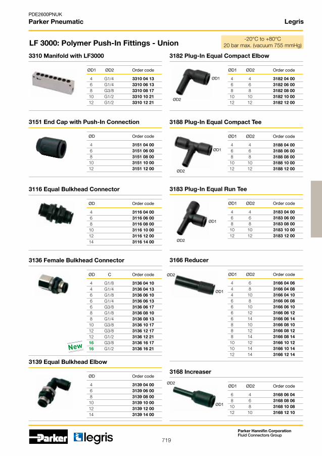
719
PDE2600PNUK
Parker Pneumatic
Parker Hannifin CorporationFluid Connectors Group
Legris
4 G1/4 3310 04 13 6 G1/4 3310 06 13 8 G3/8 3310 08 17 10 G1/2 3310 10 21 12 G1/2 3310 12 21
4 3151 04 00 6 3151 06 00 8 3151 08 00 10 3151 10 00 12 3151 12 00
4 G1/8 3136 04 10 4 G1/4 3136 04 13 6 G1/8 3136 06 10 6 G1/4 3136 06 13 6 G3/8 3136 06 17 8 G1/8 3136 08 10 8 G1/4 3136 08 13 10 G3/8 3136 10 17 12 G3/8 3136 12 17 12 G1/2 3136 12 21 16 G3/8 3136 16 17 16 G1/2 3136 16 21
4 4 3182 04 00 6 6 3182 06 00 8 8 3182 08 00 10 10 3182 10 00 12 12 3182 12 00
4 3116 04 00 6 3116 06 00 8 3116 08 00 10 3116 10 00 12 3116 12 00 14 3116 14 00
4 3139 04 00 6 3139 06 00 8 3139 08 00 10 3139 10 00 12 3139 12 00 14 3139 14 00
4 4 3188 04 00 6 6 3188 06 00 8 8 3188 08 00 10 10 3188 10 00 12 12 3188 12 00
4 4 3183 04 00 6 6 3183 06 00 8 8 3183 08 00 10 10 3183 10 00 12 12 3183 12 00
4 6 3166 04 06 4 8 3166 04 08 4 10 3166 04 10 6 8 3166 06 08 6 10 3166 06 10 6 12 3166 06 12 6 14 3166 06 14 8 10 3166 08 10 8 12 3166 08 12 8 14 3166 08 14 10 12 3166 10 12 10 14 3166 10 14 12 14 3166 12 14
6 4 3168 06 04 8 6 3168 08 06 10 8 3168 10 08 12 10 3168 12 10
ØD1
ØD1
ØD1
ØD1
ØD1
ØD2
ØD2
ØD2
ØD2
ØD2
3310 Manifold with LF3000
ØD1 ØD2 Order code
3151 End Cap with Push-In Connection
ØD Order code
3136 Female Bulkhead Connector
ØD C Order code
3182 Plug-In Equal Compact Elbow
ØD1 ØD2 Order code
LF 3000: Polymer Push-In Fittings - Union
3116 Equal Bulkhead Connector
ØD Order code
3139 Equal Bulkhead Elbow
ØD Order code
3188 Plug-In Equal Compact Tee
ØD1 ØD2 Order code
3183 Plug-In Equal Run Tee
ØD1 ØD2 Order code
3166 Reducer
ØD1 ØD2 Order code
3168 Increaser
ØD1 ØD2 Order code
-20°C to +80°C 20barmax.(vacuum755mmHg)
New

720
PDE2600PNUK
Parker Pneumatic
Parker Hannifin CorporationFluid Connectors Group
Legris
4 3126 04 00 6 3126 06 00 8 3126 08 00 10 3126 10 00 12 3126 12 00 14 3126 14 00 16 3126 16 00
4 Clip 04 00 6 Clip 06 00 8 Clip 08 00 10 Clip 10 00 12 Clip 12 00 14 Clip 14 00
2 3329 00 01 4 - 7 3329 00 02 12 3329 00 03
4 2 3320 04 00 02 4 4 3320 04 00 04 4 7 3320 04 00 07 4 12 3320 04 00 12 6 2 3320 06 00 02 6 4 3320 06 00 04 6 7 3320 06 00 07 8 2 3320 08 00 02
4 2 3321 04 00 02 4 4 3321 04 00 04 4 7 3321 04 00 07 4 12 3321 04 00 12 6 4 3321 06 00 04 6 7 3321 06 00 07 8 2 3321 08 00 02
4 3379 04 00 6 3379 06 00 8 3379 08 00
4 3381 04 00 6 3381 06 00 8 3381 08 00
4 3100 04 00 6 3100 06 00 8 3100 08 00 10 3100 10 00 12 3100 12 00 14 3100 14 00
New
LF 3000: Polymer Push-In Fittings - Union
3126 Blanking Plugs
ØD Order code
Clip Strips for Tubes
ØD Order code
ØD Order code
3329 Multi-Connector Screw Cap
Number of outlets Order code
3320 Multi-Connector Male Screw Body
o.d. tube Number of outlets Order code
3321 Multi-Connector Female Screw Body
o.d. tube Number of outlets Order code
3379 DIN Rail Connector for 2 tubes in line
Multi-Connector Assembly Photo
ØD Order code
3381 DIN Rail Connector for 3 Tubes
ØD Order code
3100 Carstick
-20°C to +80°C 20barmax.(vacuum755mmHg)
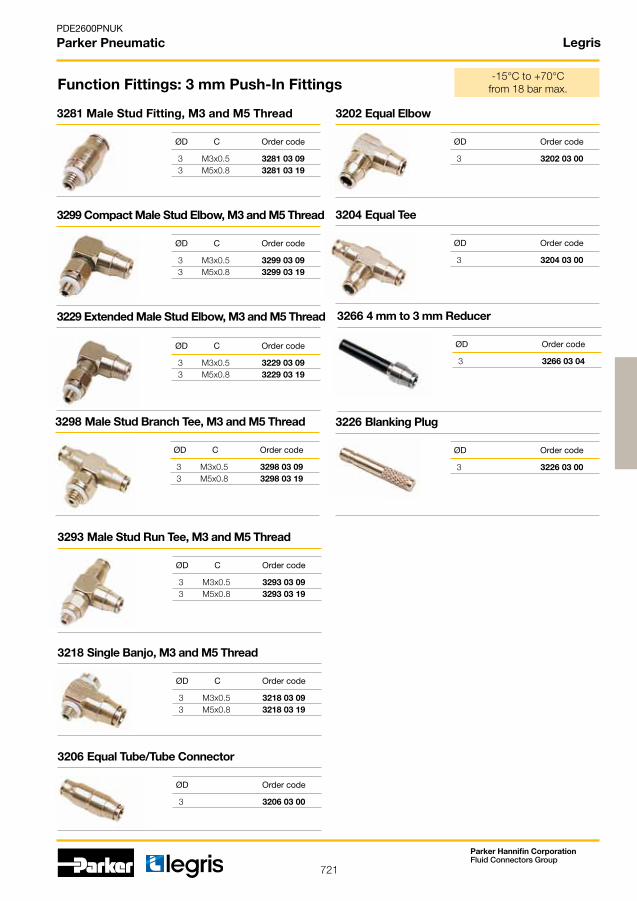
721
PDE2600PNUK
Parker Pneumatic
Parker Hannifin CorporationFluid Connectors Group
Legris
3 M3x0.5 3281 03 09 3 M5x0.8 3281 03 19
3 M3x0.5 3299 03 09 3 M5x0.8 3299 03 19
3 M3x0.5 3229 03 09 3 M5x0.8 3229 03 19
3 M3x0.5 3298 03 09 3 M5x0.8 3298 03 19
3 M3x0.5 3293 03 09 3 M5x0.8 3293 03 19
3 M3x0.5 3218 03 09 3 M5x0.8 3218 03 19
3 3206 03 00
3 3202 03 00
3 3204 03 00
3 3266 03 04
3 3226 03 00
Function Fittings: 3 mm Push-In Fittings
3281 Male Stud Fitting, M3 and M5 Thread
3299 Compact Male Stud Elbow, M3 and M5 Thread
3229 Extended Male Stud Elbow, M3 and M5 Thread
3298 Male Stud Branch Tee, M3 and M5 Thread
3293 Male Stud Run Tee, M3 and M5 Thread
3218 Single Banjo, M3 and M5 Thread
3206 Equal Tube/Tube Connector
3202 Equal Elbow
ØD C Order code
ØD C Order code
ØD C Order code
ØD C Order code
ØD C Order code
ØD C Order code
ØD Order code
ØD Order code
-15°C to +70°C from 18 bar max.
3204 Equal Tee
3266 4 mm to 3 mm Reducer
3226 Blanking Plug
ØD Order code
ØD Order code
ØD Order code

722
PDE2600PNUK
Parker Pneumatic
Parker Hannifin CorporationFluid Connectors Group
Legris
4 M5 x 0.8 7660 04 19 4 G1/8 7660 04 10 6 M5 x 0.8 7660 06 19 6 G1/8 7660 06 10 6 G1/4 7660 06 13 8 G1/8 7660 08 10 8 G1/4 7660 08 13 8 G3/8 7660 08 17
4 M5 x 0,8 7662 04 19 4 G1/8 7662 04 10 6 M5 x 0,8 7662 06 19 6 G1/8 7662 06 10 6 G1/4 7662 06 13
4 M5 x 0.8 7669 04 19 4 G1/8 7669 04 10 6 M5 x 0.8 7669 06 19 6 G1/8 7669 06 10 6 G1/4 7669 06 13 8 G1/8 7669 08 10 8 G1/4 7669 08 13 8 G3/8 7669 08 17
4 G1/8 7060 04 10 6 G1/8 7060 06 10 6 G1/4 7060 06 13 8 G1/8 7060 08 10 8 G1/4 7060 08 13 8 G3/8 7060 08 17 10 G1/4 7060 10 13 10 G3/8 7060 10 17 12 G3/8 7060 12 17 12 G1/2 7060 12 21
4 G1/8 7061 04 10 6 G1/8 7061 06 10 6 G1/4 7061 06 13 8 G1/8 7061 08 10 8 G1/4 7061 08 13 8 G3/8 7061 08 17 10 G1/4 7061 10 13 10 G3/8 7061 10 17 12 G1/2 7061 12 21
4 G1/8 7062 04 10 6 G1/8 7062 06 10 6 G1/4 7062 06 13 8 G1/8 7062 08 10 8 G1/4 7062 08 13 8 G3/8 7062 08 17
4 M5 x 0.8 7010 04 19 4 G1/8 7010 04 10 6 M5 x 0.8 7010 06 19 6 G1/8 7010 06 10 6 G1/4 7010 06 13 8 G1/8 7010 08 10 8 G1/4 7010 08 13 8 G3/8 7010 08 17 10 G1/4 7010 10 13 10 G3/8 7010 10 17 10 G1/2 7010 10 21 12 G3/8 7010 12 17 12 G1/2 7010 12 21
4 M5 x 0.8 7011 04 19 4 G1/8 7011 04 10 6 M5 x 0.8 7011 06 19 6 G1/8 7011 06 10 6 G1/4 7011 06 13 8 G1/8 7011 08 10 8 G1/4 7011 08 13 8 G3/8 7011 08 17 10 G1/4 7011 10 13 10 G3/8 7011 10 17
4 M5 x 0,8 7012 04 19 4 G1/8 7012 04 10 6 M5 x 0,8 7012 06 19 6 G1/8 7012 06 10 6 G1/4 7012 06 13 8 G1/8 7012 08 10 8 G1/4 7012 08 13 8 G3/8 7012 08 17
Function Fittings: Flow Control Regulators
7669 Miniature BSPP & M5 - supply (B)
ØD C Order code
7060 Compact BSPP - exhaust (A)
ØD C Order code
0°C to +70°C from 1 to 10 bar max.
7061 Compact BSPP - supply (B)7010 Recessed Adjust.Screw, BSPP & M5 - exhaust (A)
7660 Miniature BSPP & M5 - exhaust (A)
ØD C Order code
7662 Miniature BSPP & M5 - bi-directional (C)
ØD C Order code
ØD C Order code
7062 Compact BSPP - bi-directional (C)
ØD C Order code
ØD C Order code
7011 Recessed Adjust.Screw, BSPP & M5 - supply (B)
ØD C Order code
7012 Recessed Adjust.Screw, BSPP & M5 - bi-directional (C)
ØD C Order code

723
PDE2600PNUK
Parker Pneumatic
Parker Hannifin CorporationFluid Connectors Group
Legris
4 M5 x 0,8 7640 04 19 4 G1/8 7640 04 10 6 M5 x 0,8 7640 06 19 6 G1/8 7640 06 10
4 M5 x 0,8 7649 04 19 4 G1/8 7649 04 10 6 M5 x 0,8 7649 06 19 6 G1/8 7649 06 10
6 G1/4 7041 06 13 8 G1/8 7041 08 10 8 G1/4 7041 08 13
4 7772 04 00 6 7772 06 00 8 7772 08 00
6 G1/8 7040 06 10 6 G1/4 7040 06 13 8 G1/8 7040 08 10 8 G1/4 7040 08 13 8 G3/8 7040 08 17 10 G1/4 7040 10 13 10 G3/8 7040 10 17 12 G3/8 7040 12 17 12 G1/2 7040 12 21
4 7770 04 00 6 7770 06 00 8 7770 08 00 10 7770 10 00 12 7770 12 00
G1/8 7771 10 10 G1/4 7771 13 13 G3/8 7771 17 17 G1/2 7771 21 21
4 7776 04 00 6 7776 06 00 8 7776 08 00 10 7776 10 00 12 7776 12 00
Function Fittings: Flow Control Regulators
7041 Compact Swivel Elbow, BSPP - supply (B)
ØD C Order code
7040 Compact Swivel Elbow, BSPP - exhaust (A)
ØD C Order code
7771 In-line with Threaded Connections, BSPP, One-Way Adjust (A)
C Order code
7776 - In-line with push-in connection, One-Way Adjust (A), Panel Mountable
ØD Order code
0°C to +70°C from 1 to 10 bar max.
7640 Miniature BSPP & Metric - exhaust (A)
ØD C Order code
7649 Miniature BSPP & Metric - supply (B)
ØD C Order code
7772 - In-line with push-in connection,Bi-directional (C)
ØD Order code
7770 - In-line with push-in connection, One-Way Adjust (A)
ØD Order code
4 G1/8 7100 04 10 6 G1/8 7100 06 10 6 G1/4 7100 06 13 8 G1/8 7100 08 10 8 G1/4 7100 08 13 8 G3/8 7100 08 17 10 G1/4 7100 10 13 10 G3/8 7100 10 17 12 G3/8 7100 12 17 12 G1/2 7100 12 21 14 G1/2 7100 14 21
4 G1/8 7101 04 10 6 G1/8 7101 06 10 6 G1/4 7101 06 13 8 G1/8 7101 08 10 8 G1/4 7101 08 13 8 G3/8 7101 08 17
G1/8 7110 10 10
G1/4 7110 13 13
G3/8 7110 17 17
G1/2 7110 21 21
G1/8 7111 10 10
G1/4 7111 13 13
7100 Compact with push-in connection, BSPP - exhaust (A)
ØD C Order code
7101 Compact with push-in connection, BSPP - supply (B)
ØD C Order code
7110 Compact with Threaded Fitting, BSPP - exhaust (A)
C Order code

724
PDE2600PNUK
Parker Pneumatic
Parker Hannifin CorporationFluid Connectors Group
Legris
M5 7170 19 19 G1/8 7170 10 10 G1/4 7170 13 13 G3/8 7170 17 17 G1/2 7170 21 21
8 G1/8 7762 08 10 10 G1/4 7762 10 13 14 G3/8 7762 14 17 18 G1/2 7762 18 21
4 G1/8 7130 04 10 4 M5 x 0.8 7130 04 19 6 G1/8 7130 06 10 6 G1/4 7130 06 13 6 M5 x 0.8 7130 06 19 8 G1/8 7130 08 10 8 G1/4 7130 08 13 8 G3/8 7130 08 17 10 G1/4 7130 10 13 10 G3/8 7130 10 17 10 G1/2 7130 10 21 12 G3/8 7130 12 17 12 G1/2 7130 12 21
4 G1/8 7160 04 10 6 G1/8 7160 06 10 6 G1/4 7160 06 13 8 G1/8 7160 08 10 8 G1/4 7160 08 13 10 G1/4 7160 10 13 10 G3/8 7160 10 17 10 G1/2 7160 10 21 12 G3/8 7160 12 17 12 G1/2 7160 12 21
M5 x 0.8 7140 19 19 G1/8 7140 10 10 G1/4 7140 13 13 G3/8 7140 17 17 G1/2 7140 21 21
G1/8 7111 10 10 G1/4 7111 13 13
Function Fittings: Flow Control Regulators
7170 In-line Flow Regulator, BSPP & M5
C Order code
7762 with Universal Brass Compression Fitting, external adjust, BSPP - exhaust (A)
ØD C Order code
7130 Recessed Adjust.Screw, BSPP & M5 - exhaust (A)
ØD C Order code
7160 with Universal Brass Compression Fitting, Recessed Adjust. Screw, BSP - exhaust (A)
ØD C Order code
7140 Threaded Recessed Adjust.Screw, BSPP & M5 - exhaust (A)
C Order code
7111 Compact with Threaded Fitting, BSPP - supply (B)
C Order code
0°C to +70°C from 1 to 10 bar max.
Body in aluminium

725
PDE2600PNUK
Parker Pneumatic
Parker Hannifin CorporationFluid Connectors Group
4 7996 04 00 6 7996 06 00 8 7996 08 00 10 7996 10 00 12 7996 12 00
4 M5 x 0.8 7994 04 19 4 G1/8 7994 04 10 6 G1/8 7994 06 10 6 G1/4 7994 06 13 8 G1/8 7994 08 10 8 G1/4 7994 08 13 10 G3/8 7994 10 17 12 G3/8 7994 12 17 12 G1/2 7994 12 21
4 M5 x 0,8 7984 04 19 4 G1/8 7984 04 10 6 G1/8 7984 06 10 6 G1/4 7984 06 13 8 G1/8 7984 08 10 8 G1/4 7984 08 13 10 G3/8 7984 10 17 12 G3/8 7984 12 17 12 G1/2 7984 12 21
7996 Non-Return Valve with push-in connection
ØD Order code
7994 Non-Return Valve with push-in connection, BSPP & M5 -exhaust (A)
ØD C Order code
7984 Non-Return Valve with push-in connection, BSPP & M5 -supply (B)
ØD C Order code
Function Fittings: Non-Return Valves 0°C to +70°C from 1 to 10 bar max.
M5 X 0.8 7930 19 19 G1/8 7930 10 10 G1/4 7930 13 13 G3/8 7930 17 17 G1/2 7930 21 21
7930 Adjustable Check Valve,Double Female and BSPP and Metric Thread
ØC Order code
G1/8 7931 10 10 G1/4 7931 13 13 G3/8 7931 17 17 G1/2 7931 21 21
7931 Adjustable Check Valve Supply,Male/Female BSPP Thread
ØC Order code
G1/8 7932 10 10 G1/4 7932 13 13 G3/8 7932 17 17 G1/2 7932 21 21
7932 Adjustable Check Valve Exhaust,Male/Female BSPP Thread
ØC Order code
Legris
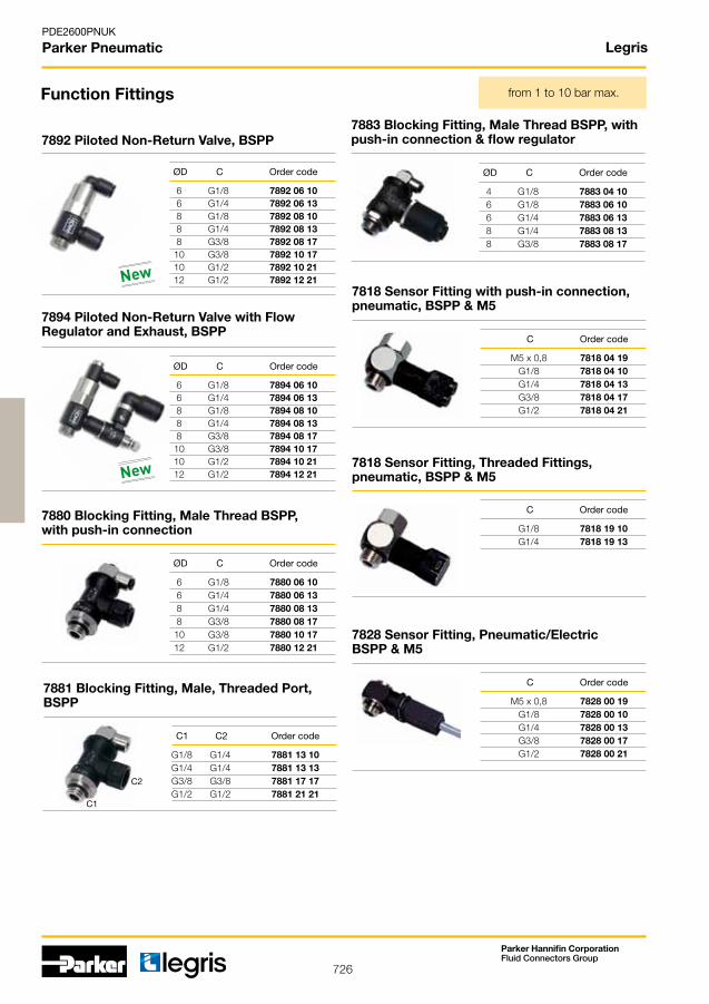
726
PDE2600PNUK
Parker Pneumatic
Parker Hannifin CorporationFluid Connectors Group
Legris
6 G1/8 7880 06 10 6 G1/4 7880 06 13 8 G1/4 7880 08 13 8 G3/8 7880 08 17 10 G3/8 7880 10 17 12 G1/2 7880 12 21
M5 x 0,8 7818 04 19 G1/8 7818 04 10 G1/4 7818 04 13 G3/8 7818 04 17 G1/2 7818 04 21
G1/8 7818 19 10 G1/4 7818 19 13
M5 x 0,8 7828 00 19 G1/8 7828 00 10 G1/4 7828 00 13 G3/8 7828 00 17 G1/2 7828 00 21
4 G1/8 7883 04 10 6 G1/8 7883 06 10 6 G1/4 7883 06 13 8 G1/4 7883 08 13 8 G3/8 7883 08 17
G1/8 G1/4 7881 13 10 G1/4 G1/4 7881 13 13 G3/8 G3/8 7881 17 17 G1/2 G1/2 7881 21 21
C1
C2
6 G1/8 7892 06 10 6 G1/4 7892 06 13 8 G1/8 7892 08 10 8 G1/4 7892 08 13 8 G3/8 7892 08 17 10 G3/8 7892 10 17 10 G1/2 7892 10 21 12 G1/2 7892 12 21
6 G1/8 7894 06 10 6 G1/4 7894 06 13 8 G1/8 7894 08 10 8 G1/4 7894 08 13 8 G3/8 7894 08 17 10 G3/8 7894 10 17 10 G1/2 7894 10 21 12 G1/2 7894 12 21
7880 Blocking Fitting, Male Thread BSPP, with push-in connection
ØD C Order code
Function Fittings
7818 Sensor Fitting with push-in connection, pneumatic, BSPP & M5
C Order code
7818 Sensor Fitting, Threaded Fittings, pneumatic, BSPP & M5
C Order code
7828 Sensor Fitting, Pneumatic/Electric BSPP & M5
C Order code
7883 Blocking Fitting, Male Thread BSPP, with push-in connection & flow regulator
ØD C Order code
7881 Blocking Fitting, Male, Threaded Port, BSPP
C1 C2 Order code
from 1 to 10 bar max.
7892 Piloted Non-Return Valve, BSPP
ØD C Order code
7894 Piloted Non-Return Valve with Flow Regulator and Exhaust, BSPP
ØD C Order code
New
New

727
PDE2600PNUK
Parker Pneumatic
Parker Hannifin CorporationFluid Connectors Group
Legris
6 G1/8 7318 06 10 6 G1/4 7318 06 13 8 G1/4 7318 08 13 10 G1/4 7318 10 13 10 G3/8 7318 10 17
4 G1/8 7801 04 10 6 G1/8 7801 06 10 6 G1/4 7801 06 13 8 G1/8 7801 08 10 8 G1/4 7801 08 13 10 G1/4 7801 10 13
4 G1/8 7300 04 10 6 G1/8 7300 06 10 6 G1/4 7300 06 13 8 G1/8 7300 08 10 8 G1/4 7300 08 13 8 G3/8 7300 08 17 10 G1/4 7300 10 13 10 G3/8 7300 10 17
6 7316 06 00 8 7316 08 00 10 7316 10 00
8 G1/4 7860 08 13 10 G1/4 7860 10 13 10 G3/8 7860 10 17 12 G3/8 7860 12 17 12 G1/2 7860 12 21
M5 7970 19 19 G1/8 7970 10 10 G1/4 7970 13 13 G3/8 7970 17 17 G1/2 7970 21 21 G3/4 7970 27 27 G1” 7970 34 34
G1/4 7861 13 13 G3/8 7861 17 17 G1/2 7861 21 21
8 G1/4 7870 08 13 10 G1/4 7870 10 13 10 G3/8 7870 10 17
4 M5 x 0.8 7800 04 19 4 G1/8 7800 04 10 6 M5 x 0.8 7800 06 19 6 G1/8 7800 06 10 6 G1/4 7800 06 13 8 G1/8 7800 08 10 8 G1/4 7800 08 13 10 G1/4 7800 10 13
G1/8 7971 10 10 G1/4 7971 13 13 G3/8 7971 17 17 G1/2 7971 21 21
from 1 to 10 bar max.
7318 Pressure Reducer, with push-in connection, BSPP
ØD C Order code
7801 3/2 Manual Switch Operated Valve, with push-in connection BSPP & M5 (control)
ØD C Order code
7300 Pressure Regulator Fitting with push-in connection, BSPP
ØD C Order code
Function Fittings
7316 Pressure Reducer, In-Line with push-in connection
ØD Order code
7860 Soft Start Valve with push-in connection, BSPP - for System isolating valve
ØD C Order code
7970 Elbow Quick Exhaust Valve, BSPP
C Order code
7861 Soft Start Valve with Threaded Fitting, BSPP - for system isolating valve
C Order code
7870 Soft Start Valve with push-in connection, BSPP - for Control valve
ØD C Order code
7800 3/2 Manual Switch Operated Valve, with push-in connection BSPP & M5 (supply)
ØD C Order code
7971 In-Line Quick Exhaust Valve male BSPT, female BSPP
C Order code
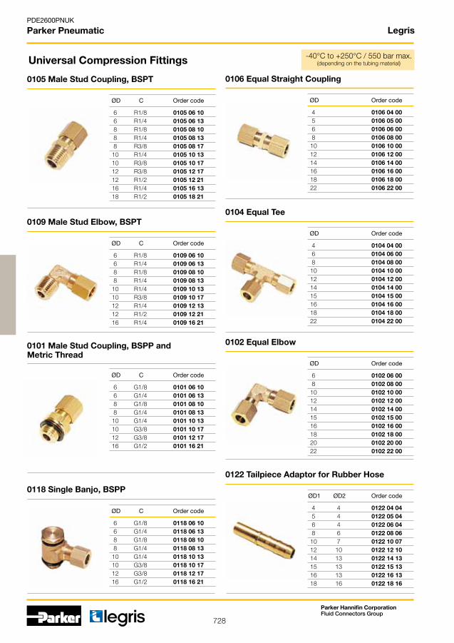
728
PDE2600PNUK
Parker Pneumatic
Parker Hannifin CorporationFluid Connectors Group
Legris
6 R1/8 0105 06 10 6 R1/4 0105 06 13 8 R1/8 0105 08 10 8 R1/4 0105 08 13 8 R3/8 0105 08 17 10 R1/4 0105 10 13 10 R3/8 0105 10 17 12 R3/8 0105 12 17 12 R1/2 0105 12 21 16 R1/4 0105 16 13 18 R1/2 0105 18 21
6 R1/8 0109 06 10 6 R1/4 0109 06 13 8 R1/8 0109 08 10 8 R1/4 0109 08 13 10 R1/4 0109 10 13 10 R3/8 0109 10 17 12 R1/4 0109 12 13 12 R1/2 0109 12 21 16 R1/4 0109 16 21
6 G1/8 0101 06 10 6 G1/4 0101 06 13 8 G1/8 0101 08 10 8 G1/4 0101 08 13 10 G1/4 0101 10 13 10 G3/8 0101 10 17 12 G3/8 0101 12 17 16 G1/2 0101 16 21
6 G1/8 0118 06 10 6 G1/4 0118 06 13 8 G1/8 0118 08 10 8 G1/4 0118 08 13 10 G1/4 0118 10 13 10 G3/8 0118 10 17 12 G3/8 0118 12 17 16 G1/2 0118 16 21
4 0106 04 00 5 0106 05 00 6 0106 06 00 8 0106 08 00 10 0106 10 00 12 0106 12 00 14 0106 14 00 16 0106 16 00 18 0106 18 00 22 0106 22 00
4 0104 04 00 6 0104 06 00 8 0104 08 00 10 0104 10 00 12 0104 12 00 14 0104 14 00 15 0104 15 00 16 0104 16 00 18 0104 18 00 22 0104 22 00
6 0102 06 00 8 0102 08 00 10 0102 10 00 12 0102 12 00 14 0102 14 00 15 0102 15 00 16 0102 16 00 18 0102 18 00 20 0102 20 00 22 0102 22 00
4 4 0122 04 04 5 4 0122 05 04 6 4 0122 06 04 8 6 0122 08 06 10 7 0122 10 07 12 10 0122 12 10 14 13 0122 14 13 15 13 0122 15 13 16 13 0122 16 13 18 16 0122 18 16
Universal Compression Fittings
0105 Male Stud Coupling, BSPT
ØD C Order code
0109 Male Stud Elbow, BSPT
ØD C Order code
0101 Male Stud Coupling, BSPP and Metric Thread
ØD C Order code
0118 Single Banjo, BSPP
ØD C Order code
0106 Equal Straight Coupling
ØD Order code
0104 Equal Tee
ØD Order code
0102 Equal Elbow
ØD Order code
0122 Tailpiece Adaptor for Rubber Hose
ØD1 ØD2 Order code
-40°C to +250°C / 550 bar max. (depending on the tubing material)

729
PDE2600PNUK
Parker Pneumatic
Parker Hannifin CorporationFluid Connectors Group
0,02 NL/h minimum flow
4 M5 x 0,8 3614 04 19 4 G1/8 3614 04 10 4 G1/4 3614 04 13 6 G1/8 3614 06 10 6 G1/4 3614 06 13 8 G1/8 3614 08 10 8 G1/4 3614 08 13 10 G3/8 3614 10 17 12 G3/8 3614 12 17 12 G1/2 3614 12 21
4 M5 x 0.8 3669 04 19
4 G1/8 3669 04 10
6 G1/8 3669 06 10
6 G1/4 3669 06 13
8 G1/8 3669 08 10
8 G1/4 3669 08 13
10 G1/4 3669 10 13
10 G3/8 3669 10 17
12 G1/4 3669 12 13
12 G3/8 3669 12 17
14 G1/2 3669 14 21
4 M5 x 0,8 3601 04 19 4 G1/8 3601 04 10 4 G1/4 3601 04 13 6 M5 x 0.8 3601 06 19 6 G1/8 3601 06 10 6 G1/4 3601 06 13 8 G1/8 3601 08 10 8 G1/4 3601 08 13 8 G3/8 3601 08 17 10 G1/4 3601 10 13 10 G3/8 3601 10 17 10 G1/2 3601 10 21 12 G1/4 3601 12 13 12 G3/8 3601 12 17 12 G1/2 3601 12 21 14 G3/8 3601 14 17 14 G1/2 3601 14 21
4 M5 x 0.8 3699 04 19 4 G1/8 3699 04 10 4 G1/4 3699 04 13 6 G1/8 3699 06 10 6 G1/4 3699 06 13 8 G1/8 3699 08 10 8 G1/4 3699 08 13 8 G3/8 3699 08 17 10 G1/4 3699 10 13 10 G3/8 3699 10 17 12 G1/4 3699 12 13 12 G3/8 3699 12 17 12 G1/2 3699 12 21 14 G3/8 3699 14 17 14 G1/2 3699 14 21
4 R1/8 3675 04 10 4 R1/4 3675 04 13 6 R1/8 3675 06 10 6 R1/4 3675 06 13 8 R1/8 3675 08 10 8 R1/4 3675 08 13 8 R3/8 3675 08 17 10 R1/4 3675 10 13 10 R3/8 3675 10 17 10 R1/2 3675 10 21 12 R1/4 3675 12 13 12 R3/8 3675 12 17 12 R1/2 3675 12 21 14 R3/8 3675 14 17 14 R1/2 3675 14 21
4 R1/8 3609 04 10 4 R1/4 3609 04 13 6 R1/8 3609 06 10 6 R1/4 3609 06 13 8 R1/8 3609 08 10 8 R1/4 3609 08 13 8 R3/8 3609 08 17 10 R1/4 3609 10 13 10 R3/8 3609 10 17 12 R1/4 3609 12 13 12 R3/8 3609 12 17 12 R1/2 3609 12 21 14 R3/8 3609 14 17 14 R1/2 3609 14 21
LF 3600: Chemical Nickel-Plated Brass Push-In Fittings
3614 Female Stud, BSPP & Metric 3669 Extended Male Stud Elbow, BSPP & M5
ØD C Order code ØD C Order code
3601 Male Stud, BSPP & M5
ØD C Order code
3699 Male Stud Elbow, BSPP & M5
ØD C Order code
-20°C to +150°C 30 bar max.
20 bar max.
3675 Male Stud, BSPT
ØD C Order code
3609 Male Stud Elbow, BSPT
ØD C Order code
20 bar max.

730
PDE2600PNUK
Parker Pneumatic
Parker Hannifin CorporationFluid Connectors Group
Legris
4 M5 x 0.8 3698 04 19 4 G1/8 3698 04 10 6 G1/8 3698 06 10 6 G1/4 3698 06 13 8 G1/8 3698 08 10 8 G1/4 3698 08 13 10 G1/4 3698 10 13 12 G3/8 3698 12 17 14 G1/2 3698 14 21
4 M5 x 0,8 3693 04 19 4 G1/8 3693 04 10 6 G1/8 3693 06 10 6 G1/4 3693 06 13 8 G1/8 3693 08 10 8 G1/4 3693 08 13 10 G1/4 3693 10 13 12 G3/8 3693 12 17 14 G1/2 3693 14 21
4 G1/8 3636 04 10 6 G1/8 3636 06 10 6 G1/4 3636 06 13 8 G1/8 3636 08 10 8 G1/4 3636 08 13 10 G3/8 3636 10 17 12 G3/8 3636 12 17 12 G1/2 3636 12 21
4 M5 x 0.8 3618 04 19 4 G1/8 3618 04 10 6 M5 x 0.8 3618 06 19 6 G1/8 3618 06 10 6 G1/4 3618 06 13 8 G1/8 3618 08 10 8 G1/4 3618 08 13 10 G3/8 3618 10 17
4 3602 04 00 6 3602 06 00 8 3602 08 00 10 3602 10 00 12 3602 12 00 14 3602 14 00
4 3604 04 00 6 3604 06 00 8 3604 08 00 10 3604 10 00 12 3604 12 00 14 3604 14 00
4 3606 04 00 6 3606 06 00 8 3606 08 00 10 3606 10 00 12 3606 12 00 14 3606 14 00
4 3616 04 00 6 3616 06 00 8 3616 08 00 10 3616 10 00 12 3616 12 00 14 3616 14 00
4 3639 04 00 6 3639 06 00 8 3639 08 00 10 3639 10 00 12 3639 12 00 14 3639 14 00
-20°C to +150°C 30 bar max.
3698 Male Stud Branch Tee, BSPP & M5
3693 Male Stud Run Tee, BSPP & M5
ØD C Order code
ØD C Order code
3636 Female Bulkhead Connector, BSPP
ØD C Order code
LF 3600: Chemical Nickel-Plated Brass Push-In Fittings
3618 Single Banjo, BSPP & M5
ØD C Order code
3602 Equal Elbow
ØD Order code
3604 Equal Tee
ØD Order code
3606 Equal Tube to Tube Connector
ØD Order code
3616 Equal Bulkhead Connector
ØD Order code
3639 Equal Bulkhead Elbow
ØD Order code

731
PDE2600PNUK
Parker Pneumatic
Parker Hannifin CorporationFluid Connectors Group
Legris
6 4 3668 06 04
4 3626 04 00 6 3626 06 00 8 3626 08 00 10 3626 10 00 12 3626 12 00 14 3626 14 00
4 6 3666 04 06 4 8 3666 04 08 6 8 3666 06 08 6 10 3666 06 10 6 12 3666 06 12 8 10 3666 08 10 8 12 3666 08 12 8 14 3666 08 14 10 12 3666 10 12 10 14 3666 10 14 12 14 3666 12 14
ØD1
ØD2
3668 Plug-In Increaser
ØD1 ØD2 Order code
LF 3600: Chemical Nickel-Plated Brass Push-In Fittings
3626 Blanking Plug
ØD Order code
3666 Plug-In Reducer
ØD1 ØD2 Order code
-20°C to +150°C 30 bar max.

732
PDE2600PNUK
Parker Pneumatic
Parker Hannifin CorporationFluid Connectors Group
Legris
M5 x 0,8 G1/8 0906 10 19 G1/8 G1/4 0906 10 13 G1/8 G3/8 0906 10 17 G1/4 G3/8 0906 13 17 G1/4 G1/2 0906 13 21 G3/8 G1/2 0906 17 21
R1/8 R1/8 0900 00 10 R1/4 R1/4 0900 00 13 R3/8 R3/8 0900 00 17 R1/2 R1/2 0900 00 21 R3/4 R3/4 0900 00 27 R1” R1” 0900 00 34 R1/8 R1/4 0900 10 13 R1/8 R3/8 0900 10 17 R1/4 R3/8 0900 13 17 R1/4 R1/2 0900 13 21 R3/8 R1/2 0900 17 21 R1/2 R3/4 0900 21 27 R3/4 R1” 0900 27 34
M5 x 0.8 G1/8 0902 19 10 M5 x 0.8 M5 x 0.8 0902 00 19 G1/8 G1/8 0902 00 10 G1/4 G1/4 0902 00 13 G3/8 G3/8 0902 00 17 G1/2 G1/2 0902 00 21 G3/4 G3/4 0902 00 27 G1/8 G1/4 0902 10 13 G1/4 G3/8 0902 13 17
G1/8 0907 00 10 G1/4 0907 00 13
M5 x 0.8 0912 00 19 G1/8 0912 00 10 G1/4 0912 00 13 G3/8 0912 00 17 G1/2 0912 00 21 G3/4 0912 00 27
G1/8 R1/8 0913 00 10 G1/4 R1/4 0913 00 13 G3/8 R3/8 0913 00 17 G1/2 R1/2 0913 00 21 G3/4 R3/4 0913 00 27
C1
C1
C1
C2
M5 x 0,8 M5 x 0,8 0901 00 19
M5 x 0,8 G1/8 0901 19 10
C1
C2
C2
C2
R1/4 G1/8 0904 10 13R3/8 G1/8 0904 10 17 R3/8 G1/4 0904 13 17 R1/2 G1/4 0904 13 21 R1/2 G3/8 0904 17 21 R3/4 G3/8 0904 17 27R3/4 G1/2 0904 21 27
C1
C2
G1/8 M5 x 0.8 0905 19 10 G1/4 G1/8 0905 10 13 G3/8 G1/8 0905 10 17 G3/8 G1/4 0905 13 17 G1/2 G1/4 0905 13 21 G1/2 G3/8 0905 17 21 G3/4 G3/8 0905 17 27 G3/4 G1/2 0905 21 27
C1
C2
0906 Increaser Male to Female BSPP & M5
C1 C2 Order code
Pneumatic Accessories in Nickel-Plated Brass
0900 Straight Male, Unequal Adaptor, BSPT
C1 C2 Order code
0902 Staight Female, Equal/Unequal Adaptor, BSPP & M5
C1 C2 Order code
0907 Female Extended Adaptor Male/Female BSPP
C Order code
0912 Equal Female Stud Elbow, BSPP & M5
C Order code
0913 Equal Female Stud Elbow BSPP, Male BSPT
C1 C2 Order code
-10°C to +80°C 60 bar max.
0901 Equal/Unequal Adaptor, BSPP & M5
C1 C2 Order code
0904 Reducer Male BSPT to Female BSPP
C1 C2 Order code
0905 Reducer Male to Female BSPP & M5
C1 C2 Order code
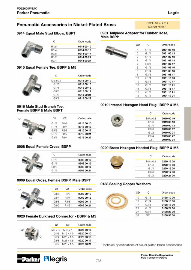
733
PDE2600PNUK
Parker Pneumatic
Parker Hannifin CorporationFluid Connectors Group
Legris
G1/8 R1/8 0916 00 10 G1/4 R1/4 0916 00 13 G3/8 R3/8 0916 00 17 G1/2 R1/2 0916 00 21 G3/4 R3/4 0916 00 27
G1/8 0908 00 10 G1/4 0908 00 13 G3/8 0908 00 17 G1/2 0908 00 21
G1/8 R1/8 0909 00 10
G1/4 R1/4 0909 00 13
G3/8 R3/8 0909 00 17
G1/2 R1/2 0909 00 21
M5 x 0,8 0919 00 19 G1/8 0919 00 10 G1/4 0919 00 13 G3/8 0919 00 17 G1/2 0919 00 21 G3/4 0919 00 27 G1” 0919 00 34
M5 x 0,8 0220 19 00 G1/8 0220 10 00 G1/4 0220 13 00 G3/8 0220 17 00 G1/2 0220 21 00
M5 x 0.8 M10 x 1 0920 00 19 G1/8 M16 x 1.5 0920 00 10 G1/4 M20 x 1.5 0920 00 13 G3/8 M26 x 1.5 0920 00 17 G1/2 M28 x 1.5 0920 00 21
6 G1/8 0931 06 10 6 G1/4 0931 06 13 7 G1/8 0931 07 10 7 G1/4 0931 07 13 7 G3/8 0931 07 17 8 G1/8 0931 08 10 8 G1/4 0931 08 13 8 G3/8 0931 08 17 10 G1/4 0931 10 13 10 G3/8 0931 10 17 10 G1/2 0931 10 21 15 G3/8 0931 15 17 15 G1/2 0931 15 21 18 G1/2 0931 18 21
10 G1/8 0138 10 00 13 G1/4 0138 13 00 17 G3/8 0138 17 00 21 G1/2 0138 21 00 27 G3/4 0138 27 00 33 G1” 0138 33 00
M5 x 0.8 0915 00 19 G1/8 0915 00 10 G1/4 0915 00 13 G3/8 0915 00 17 G1/2 0915 00 21 G3/4 0915 00 27
R1/8 0914 00 10 R1/4 0914 00 13R3/8 0914 00 17 R1/2 0914 00 21R3/4 0914 00 27
C1
C1
C1
C2
C2
C2
Pneumatic Accessories in Nickel-Plated Brass
0916 Male Stud Branch Tee, Female BSPP & Male BSPT
C1 C2 Order code
0908 Equal Female Cross, BSPP
C Order code
0909 Equal Cross, Female BSPP, Male BSPT
C1 C2 Order code
0919 Internal Hexagon Head Plug , BSPP & M5
C Order code
0220 Brass Hexagon Headed Plug, BSPP & M5
C Order code
0920 Female Bulkhead Connector - BSPP & M5
C1 C2 Order code
0931 Tailpiece Adaptor for Rubber Hose, Male BSPP
ØD C Order code
0138 Sealing Copper Washers
ØD C Order code
0915 Equal Female Tee, BSPP & M5
C Order code
0914 Equal Male Stud Elbow, BSPT
C Order code
-10°C to +80°C 60 bar max.*
*Technical specifications of nickel-plated brass accessories

734
PDE2600PNUK
Parker Pneumatic
Parker Hannifin CorporationFluid Connectors Group
Legris
0605 12 12
G1/8 M5 x 0.8 7 3311 19 10 07G1/4 G1/8 2 3311 10 13 02 G1/4 G1/8 3 3311 10 13 03 G1/4 G1/8 4 3311 10 13 04 G1/4 G1/8 5 3311 10 13 05 G1/4 G1/8 6 3311 10 13 06 G3/8 G1/4 2 3311 13 17 02 G3/8 G1/4 3 3311 13 17 03 G3/8 G1/4 4 3311 13 17 04 G3/8 G1/4 5 3311 13 17 05 G3/8 G1/4 6 3311 13 17 06
G1/4 G1/8 2 3313101302 G1/4 G1/8 3 3313101303 G1/4 G1/8 4 3313101304 G1/4 G1/8 5 3313101305 G3/8 G1/4 2 3313131702 G3/8 G1/4 3 3313131703 G3/8 G1/4 4 3313131704 G3/8 G1/4 5 3313131705 G1/2 G1/4 3 3313132103 G1/2 G1/4 4 3313132104 G1/2 G1/4 5 3313132105
M5 x 0.8 3312 00 19 G1/8 3312 00 10 G1/4 3312 00 13 G3/8 3312 00 17 G1/2 3312 00 21
C1
C1
C2
C2
G1/8 0670 00 10 G1/4 0670 00 13 G3/8 0670 00 17 G1/2 0670 00 21 G3/4 0670 00 27
G1/8 0677 00 10 G1/4 0677 00 13 G3/8 0677 00 17 G1/2 0677 00 21 G3/4 0677 00 27 G1” 0677 00 34
M5 x 0.8 0674 00 19 G1/8 0674 00 10 G1/4 0674 00 13 G3/8 0674 00 17 G1/2 0674 00 21 G3/4 0674 00 27
M5 x 0.8 0673 00 19 G1/8 0673 00 10 G1/4 0673 00 13 G3/8 0673 00 17 G1/2 0673 00 21
G1/8 0672 00 10 G1/4 0672 00 13 G3/8 0672 00 17 G1/2 0672 00 21
Pneumatic Accessories -10°C to +80°C 20 bar max.
Technical specifications of aluminium anodised manifolds
0670 Threaded Silencer, BSPP
C Order code
0677 Silencer, Miniature, BSPP
C Order code
0674 Threaded Silencer, Male BSPP & M5
C Order code
0673 Threaded Silencer, Male BSPP & M5
C Order code
0672 Flow-Control Silencer, Male BSPP
C Order code
-20° to +150°C12 bar
-20° to +150°C12 bar
-20° to +150°C12 bar
-10° to +80°C10 bar
-20° to +150°C12 bar
0605 Fluoropolymer Tape
Order code
3311 Female Manifold BSPP & M5
C1 C2 Number of Order code Outlets
3313 Double Female Manifold BSPP
C1 C2 Number of Order code Outlets
3312 Female Cross Manifold BSPP & M5
C Order code
-250° to +260°C

735
PDE2600PNUK
Parker Pneumatic
Parker Hannifin CorporationFluid Connectors Group
4 M5 x 0.8 3805 04 19 4 R1/8 3805 04 10 4 R1/4 3805 04 13 6 R1/8 3805 06 10 6 R1/4 3805 06 13 8 R1/8 3805 08 10 8 R1/4 3805 08 13 8 R3/8 3805 08 17 10 R1/4 3805 10 13 10 R3/8 3805 10 17 12 R1/4 3805 12 13 12 R3/8 3805 12 17 12 R1/2 3805 12 21
4 M5 x 0.8 3801 04 19
4 G1/8 3801 04 10
6 M5 x 0.8 3801 06 19
6 G1/8 3801 06 10
6 G1/4 3801 06 13
8 G1/8 3801 08 10
8 G1/4 3801 08 13
8 G3/8 3801 08 17
10 G1/4 3801 10 13
10 G3/8 3801 10 17
12 G1/4 3801 12 13
14 G3/8 3801 12 17
4 G1/8 3879 04 10
4 G1/4 3879 04 13
6 G1/8 3879 06 10
6 G1/4 3879 06 13
8 G1/8 3879 08 10
8 G1/4 3879 08 13
8 G3/8 3879 08 17
10 G1/4 3879 10 13
10 G3/8 3879 10 17
12 G1/4 3879 12 13
12 G3/8 3879 12 17
12 G1/2 3879 12 21
4 R1/8 3889 04 10
4 R1/4 3889 04 13
6 R1/8 3889 06 10
6 R1/4 3889 06 13
8 R1/8 3889 08 10
8 R1/4 3889 08 13
8 R3/8 3889 08 17
10 R1/4 3889 10 13
10 R3/8 3889 10 17
12 R1/4 3889 12 13
12 R3/8 3889 12 17
12 R1/2 3889 12 21
4 3802 04 00 6 3802 06 00 8 3802 08 00 10 3802 10 00 12 3802 12 00
4 3804 04 00 6 3804 06 00 8 3804 08 00 10 3804 10 00 12 3804 12 00
4 3806 04 00 6 3806 06 00 8 3806 08 00 10 3806 10 00 12 3806 12 00
4 3816 04 00 6 3816 06 00 8 3816 08 00 10 3816 10 00 12 3816 12 00
4 6 3866 04 06 4 8 3866 04 08 6 8 3866 06 08 6 10 3866 06 10 8 10 3866 08 10 8 12 3866 08 12 10 12 3866 10 12IP51
ØD1
ØD2
3805 Male Stud, BSPT & M5
LF 3800: Stainless Steel Push-In Fittings
ØD C Order code
3801 Male Stud, BSPP & M5
ØD C Order code
3879 Male Stud Elbow, BSPP
ØD C Order code
3889 Male Stud Elbow, BSPT
ØD C Order code
3802 Equal Elbow
ØD Order code
3804 Equal Tee
ØD Order code
3806 Equal Straight Union
ØD Order code
3816 Equal Bulkhead Union
ØD Order code
3866 Plug-In Reducer
ØD1 ØD2 Order code
-20°C to +120°C 30 bar max.
20 bar max.
20 bar max.
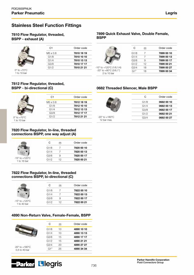
736
PDE2600PNUK
Parker Pneumatic
Parker Hannifin CorporationFluid Connectors Group
Legris
G1/8 7 7820 00 10
G1/4 7 7820 00 13
G3/8 9 7820 00 17
G1/2 12 7820 00 21
G1/8 7 7822 00 10
G1/4 7 7822 00 13
G3/8 9 7822 00 17
G1/2 12 7822 00 21
G1/8 10 4890 10 10
G1/4 10 4890 13 13
G3/8 15 4890 17 17
G1/2 15 4890 21 21
G3/4 20 4890 27 27
G1” 25 4890 34 34
G1/8 0682 00 10
G1/4 0682 00 13
G3/8 0682 00 17
G1/2 0682 00 21
G3/4 0682 00 27
M5 x 0.8 7810 19 19 G1/8 7810 10 10 G1/4 7810 13 13 G3/8 7810 17 17 G1/2 7810 21 21
M5 x 0.8 7812 19 19 G1/8 7812 10 10 G1/4 7812 13 13 G3/8 7812 17 17 G1/2 7812 21 21
G1/8 7 7899 00 10 G1/4 7 7899 00 13 G3/8 9 7899 00 17 G1/2 12 7899 00 21 G3/4 18 7899 00 27 G1” 18 7899 00 34
DN
DN
DN
DN
7820 Flow Regulator, In-line, threaded connections BSPP, one way adjust (A)
C Order code
7822 Flow Regulator, In-line, threaded connections BSPP, bi-directional (C)
C Order code
4890 Non-Return Valve, Female-Female, BSPP
0682 Threaded Silencer, Male BSPP
C Order code
C Order code
Stainless Steel Function Fittings
7810 Flow Regulator, threaded, BSPP - exhaust (A)
C1 Order code
7812 Flow Regulator, threaded, BSPP - bi-directional (C)
C1 Order code
7899 Quick Exhaust Valve, Double Female, BSPP
C Order code
0° to +70°C1 to 10 bar
0° to +70°C1 to 10 bar
-20° to +180°C12 bar max.
-10° to +120°C (1/8,1/4)-20° to +80°C (3/8,1”)
2 to 10 bar
-15° to +120°C1 to 16 bar
-15° to +120°C1 to 40 bar
-20° to +180°C0,5 to 40 bar

737
PDE2600PNUK
Parker Pneumatic
Parker Hannifin CorporationFluid Connectors Group
Legris
G1/8 R1/8 1844 10 10
G1/4 R1/4 1844 13 13
G3/8 R3/8 1844 17 17
G1/2 R1/2 1844 21 21
G1/8 1843 10 10
G1/4 1843 13 13
G3/8 1843 17 17
G1/2 1843 21 21
G1/8 1845 10 10
G1/4 1845 13 13
G3/8 1845 17 17
G1/2 1845 21 21
G1/8 1855 10 10
G1/4 1855 13 13
G3/8 1855 17 17
G1/2 1855 21 21
G1/8 1817 00 10
G1/4 1817 00 13
G3/8 1817 00 17
G1/2 1817 00 21
1/8 G1/8 1864 11 10
1/4 G1/4 1864 14 13
3/8 G3/8 1864 18 17
1/2 G1/2 1864 22 21
R1/8 1/8 1867 10 11
R1/4 1/4 1867 13 14
R3/8 3/8 1867 17 18
R1/2 1/2 1867 21 22
R1/4 G1/8 1863 13 10
R3/8 G1/8 1863 17 10
R3/8 G1/4 1863 17 13
R1/2 1/4 1863 21 13
R1/2 3/8 1863 21 17
7 R1/8 1823 07 10
7 R1/4 1823 07 13
10 R1/4 1823 10 13
10 R3/8 1823 10 17
13 R3/8 1823 13 17
16 R1/2 1823 16 21
R1/8 0285 10 00
R1/4 0285 13 00
R3/8 0285 17 00
R1/2 0285 21 00
R3/4 0285 27 00
C1
C1
C1
C1
C2
C2
C2
C2
1844 Equal Male Stud Elbow, BSPT, female BSPP
C1 C2 Order code
Stainless Steel Accessories
1843 Equal Elbow, Female BSPP
C Order code
1845 Equal Tee, Triple Female, BSPP
C Order code
1855 Double Female Sleeve, BSPP
C Order code
1817 Bulkhead Adaptor, BSPP
C Order code
1864 Male NPT to Female BSPP Adaptor
1867 Male BSPT to Female NPT Adaptor
C1 C2 Order code
C1 C2 Order code
1863 Reducer BSPT to Female BSPP
C1 C2 Order code
1823 Tailpiece Adaptor for Rubber Hose, Male BSPT
ØD C Order code
0285 Plug, Internal Hexagon Headed, BSPT
C Order code
-20°C to +180°C 150 bar max.

738
PDE2600PNUK
Parker Pneumatic
Parker Hannifin CorporationFluid Connectors Group
Legris
4 2.7 30 1025P04 00 27 4 2.7 30 1025P04 01 27 4 2.7 30 1025P04 02 27 4 2.7 30 1025P04 03 27 4 2.7 30 1025P04 04 27 4 2.7 30 1025P04 05 27 4 2.7 30 1025P04 06 27 6 4 35 1025P06 00 6 4 35 1025P06 01 6 4 35 1025P06 02 6 4 35 1025P06 03 6 4 35 1025P06 04 6 4 35 1025P06 05 6 4 35 1025P06 06 8 6 55 1025P08 00 8 6 55 1025P08 01 8 6 55 1025P08 02 8 6 55 1025P08 03 8 6 55 1025P08 04 8 6 55 1025P08 05 8 6 55 1025P08 06 10 7.5 75 1025P10 00 75 10 7.5 75 1025P10 01 75 10 7.5 75 1025P10 04 75 12 9 75 1025P12 00 09 12 9 75 1025P12 01 09 12 9 75 1025P12 04 09 14 11 100 1025P14 00 11 14 11 100 1025P14 01 11 14 11 100 1025P14 04 11
13.5 4 x 2.7 35 4 1010P04 00M04 16 4 x 2.7 45 7 1010P04 00M07 18.5 6 x 4 55 4 1010P06 00M04 22 6 x 4 60 7 1010P06 00M07 19.2 8 x 6 45 2 1010P08 00M2
4 2.7 30 2010P04 00 27 4 2.7 30 2010P04 01 27 4 2.7 30 2010P04 04 27 6 4 35 2010P06 00 6 4 35 2010P06 01 6 4 35 2010P06 04 8 6 55 2005P08 00 8 6 55 2005P08 01 8 6 55 2005P08 04 10 8 90 2005P10 00 10 8 90 2005P10 01 10 8 90 2005P10 04
4 2.7 30 1100P04 00 27 4 2.7 30 1100P04 01 27 4 2.7 30 1100P04 02 27 4 2.7 30 1100P04 03 27 4 2.7 30 1100P04 04 27 4 2.7 30 1100P04 05 27 4 2.7 30 1100P04 06 27 6 4 35 1100P06 00 6 4 35 1100P06 01 6 4 35 1100P06 02 6 4 35 1100P06 03 6 4 35 1100P06 04 6 4 35 1100P06 05 6 4 35 1100P06 06 8 6 55 1100P08 00 8 6 55 1100P08 01 8 6 55 1100P08 02 8 6 55 1100P08 03 8 6 55 1100P08 04 8 6 55 1100P08 05 8 6 55 1100P08 06 10 7.5 75 1100P10 00 75 10 7.5 75 1100P10 01 75 10 7.5 75 1100P10 04 75 12 9 75 1100P12 00 09 12 9 75 1100P12 01 09 12 9 75 1100P12 04 09 14 12 100 1100P14 00 14 12 100 1100P14 01 14 12 100 1100P14 04
1025P Semi-Rigid Polyamide Tubing, 25 m Rolls
o.d. tubing i.d. tubing R minimum bend Order code mm mm radius for tube at ambient temp. in mm
Pneumatic Tubing
2005P-2010P Semi-rigid Polyamide, 500m & 1000m Reels
1010P Multitube Semi-Rigid Polyamide
o.d. PVC o.d. x i.d. R minimum bend Number Order code sheath semi rigid radius at 20OC of tubes mm nylon mm mm
o.d. tubing i.d. tubing R minimum bend Order code mm mm radius for tube at ambient temp. in mm
1100P Semi-Rigid Polyamide Tubing,100 m Rolls
o.d. tubing i.d. tubing R minimum bend Order code mm mm radius for tube at ambient temp. in mm
-40°C to +100°C 50 bar max.
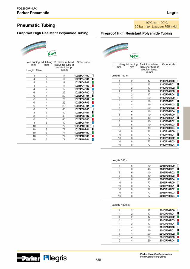
739
PDE2600PNUK
Parker Pneumatic
Parker Hannifin CorporationFluid Connectors Group
Legris
4 2 17 1025P04R00 4 2 17 1025P04R01 4 2 17 1025P04R02 4 2 17 1025P04R03 4 2 17 1025P04R04 6 4 29 1025P06R00 6 4 29 1025P06R01 6 4 29 1025P06R02 6 4 29 1025P06R03 6 4 29 1025P06R04 8 6 40 1025P08R00 8 6 40 1025P08R01 8 6 40 1025P08R02 8 6 40 1025P08R03 8 6 40 1025P08R04 10 8 77 1025P10R00 10 8 77 1025P10R01 10 8 77 1025P10R02 10 8 77 1025P10R03 10 8 77 1025P10R04
4 2 17 1100P04R00 4 2 17 1100P04R01 4 2 17 1100P04R02 4 2 17 1100P04R03 4 2 17 1100P04R04 6 4 29 1100P06R00 6 4 29 1100P06R01 6 4 29 1100P06R02 6 4 29 1100P06R03 6 4 29 1100P06R04 8 6 40 1100P08R00 8 6 40 1100P08R01 8 6 40 1100P08R02 8 6 40 1100P08R03 8 6 40 1100P08R04 10 8 77 1100P10R00 10 8 77 1100P10R01 10 8 77 1100P10R02 10 8 77 1100P10R03 10 8 77 1100P10R04
8 6 40 2005P08R00 8 6 40 2005P08R01 8 6 40 2005P08R02 8 6 40 2005P08R03 8 6 40 2005P08R04 10 8 77 2005P10R00 10 8 77 2005P10R01 10 8 77 2005P10R02 10 8 77 2005P10R03 10 8 77 2005P10R04
4 2 17 2010P04R00 4 2 17 2010P04R01 4 2 17 2010P04R02 4 2 17 2010P04R03 4 2 17 2010P04R04 6 4 29 2010P06R00 6 4 29 2010P06R01 6 4 29 2010P06R02 6 4 29 2010P06R03 6 4 29 2010P06R04
Length: 100 m
Pneumatic Tubing
Fireproof High Resistant Polyamide Tubing Fireproof High Resistant Polyamide Tubing
o.d. tubing i.d. tubing R minimum bend Order code mm mm radius for tube at ambient temp. in mmLength: 25 m
Length: 500 m
Length: 1000 m
o.d. tubing i.d. tubing R minimum bend Order code mm mm radius for tube at ambient temp. in mm
-40°C to +100°C 50barmax.(vacuum755mHg)
NewNew
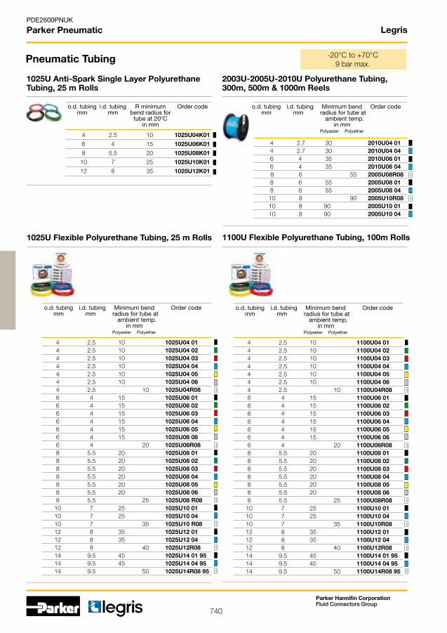
740
PDE2600PNUK
Parker Pneumatic
Parker Hannifin CorporationFluid Connectors Group
Legris
4 2.5 10 1025U04 01 4 2.5 10 1025U04 02 4 2.5 10 1025U04 03 4 2.5 10 1025U04 04 4 2.5 10 1025U04 05 4 2.5 10 1025U04 06 4 2.5 10 1025U04R08 6 4 15 1025U06 01 6 4 15 1025U06 02 6 4 15 1025U06 03 6 4 15 1025U06 04 6 4 15 1025U06 05 6 4 15 1025U06 06 6 4 20 1025U06R08 8 5.5 20 1025U08 01 8 5.5 20 1025U08 02 8 5.5 20 1025U08 03 8 5.5 20 1025U08 04 8 5.5 20 1025U08 05 8 5.5 20 1025U08 06 8 5.5 25 1025U08 R08 10 7 25 1025U10 01 10 7 25 1025U10 04 10 7 35 1025U10 R08 12 8 35 1025U12 01 12 8 35 1025U12 04 12 8 40 1025U12R08 14 9.5 45 1025U14 01 95 14 9.5 45 1025U14 04 95 14 9.5 50 1025U14R08 95
4 2.7 30 2010U04 01 4 2.7 30 2010U04 04 6 4 35 2010U06 01 6 4 35 2010U06 04 8 6 55 2005U08R08 8 6 55 2005U08 01 8 6 55 2005U08 04 10 8 90 2005U10R08 10 8 90 2005U10 01 10 8 90 2005U10 04
4 2.5 10 1100U04 01 4 2.5 10 1100U04 02 4 2.5 10 1100U04 03 4 2.5 10 1100U04 04 4 2.5 10 1100U04 05 4 2.5 10 1100U04 06 4 2.5 10 1100U04R08 6 4 15 1100U06 01 6 4 15 1100U06 02 6 4 15 1100U06 03 6 4 15 1100U06 04 6 4 15 1100U06 05 6 4 15 1100U06 06 6 4 20 1100U06R08 8 5.5 20 1100U08 01 8 5.5 20 1100U08 02 8 5.5 20 1100U08 03 8 5.5 20 1100U08 04 8 5.5 20 1100U08 05 8 5.5 20 1100U08 06 8 5.5 25 1100U08R08 10 7 25 1100U10 01 10 7 25 1100U10 04 10 7 35 1100U10R08 12 8 35 1100U12 01 12 8 35 1100U12 04 12 8 40 1100U12R08 14 9.5 45 1100U14 01 95 14 9.5 45 1100U14 04 95 14 9.5 50 1100U14R08 95
clear
clear
clear
clear
clear
clear
clear
clear
clear
clear
clear
clearclear
clear
Pneumatic Tubing
1025U Flexible Polyurethane Tubing, 25 m Rolls
o.d. tubing i.d. tubing Minimum bend Order code mm mm radius for tube at ambient temp. in mm Polyester Polyether
2003U-2005U-2010U Polyurethane Tubing, 300m, 500m & 1000m Reels
o.d. tubing i.d. tubing Minimum bend Order code mm mm radius for tube at ambient temp. in mm Polyester Polyether
1100U Flexible Polyurethane Tubing, 100m Rolls
o.d. tubing i.d. tubing Minimum bend Order code mm mm radius for tube at ambient temp. in mm Polyester Polyether
-20°C to +70°C 9 bar max.
4 2.5 10 1025U04K01
6 4 15 1025U06K01
8 5.5 20 1025U08K01
10 7 25 1025U10K01
12 8 35 1025U12K01
1025U Anti-Spark Single Layer Polyurethane Tubing, 25 m Rolls
o.d. tubing i.d. tubing R minimum Order code mm mm bend radius for tube at 20OC in mm

741
PDE2600PNUK
Parker Pneumatic
Parker Hannifin CorporationFluid Connectors Group
4 2.5 10 1100U04A01
6 4 15 1100U06A01
8 5.5 25 1100U08A01
10 7 35 1100U10A01
12 8 45 1100U12A01
1100U Anti-Static Polyurethane Tubing
o.d. tubing i.d. tubing R minimum Order code mm mm bend radius for tube at 20OC in mm
Resistivity: 103 to 106 Ω
4 2.5 10 1420U04 11
4 2.5 10 1420U04 44
4 2.5 10 1420U04 41
6 4 15 1420U06 11
6 4 15 1420U06 44
6 4 15 1420U06 41
8 5.5 20 1420U08 11
8 5.5 20 1420U08 44
8 5.5 20 1420U08 41
1420U Flexible Polyurethane Twin Tubing
o.d. tubing i.d. tubing R minimum Order code mm mm bend radius for tube at 20OC in mm
4 2.5 16 1015Y04F00 4 2.5 16 1015Y04F01 4 2.5 16 1015Y04F02 4 2.5 16 1015Y04F03 4 2.5 16 1015Y04F04 4 2.5 16 1015Y04F05 4 2.5 16 1015Y04F10 6 4 32 1015Y06F00 6 4 32 1015Y06F01 6 4 32 1015Y06F02 6 4 32 1015Y06F03 6 4 32 1015Y06F04 6 4 32 1015Y06F05 6 4 32 1015Y06F10 8 5.75 40 1015Y08F00 8 5.75 40 1015Y08F01 8 5.75 40 1015Y08F02 8 5.75 40 1015Y08F03 8 5.75 40 1015Y08F04 8 5.75 40 1015Y08F05 8 5.75 40 1015Y08F10 10 7 40 1015Y10F00 10 7 40 1015Y10F01 10 7 40 1015Y10F02 10 7 40 1015Y10F03 10 7 40 1015Y10F04 10 7 40 1015Y10F05 10 7 40 1015Y10F10
clear
1015Y..F Advanced Polyethylene (APE) Tubing
o.d. tubing i.d. tubing Minimum bend Order code mm mm radius for tube at ambient temp. in mm Polyethylene
clearclear
clear
Pneumatic Tubing -40°C to +95°C 16 bar max.
Legris
Drum 150 m

742
PDE2600PNUK
Parker Pneumatic
Parker Hannifin CorporationFluid Connectors Group
Legris - PE Tubing
4 2.5 16 1030Y04F00 4 2.5 16 1030Y04F01 4 2.5 16 1030Y04F02 4 2.5 16 1030Y04F03 4 2.5 16 1030Y04F04 4 2.5 16 1030Y04F05 4 2.5 16 1030Y04F10 6 4 32 1030Y06F00 6 4 32 1030Y06F01 6 4 32 1030Y06F02 6 4 32 1030Y06F03 6 4 32 1030Y06F04 6 4 32 1030Y06F05 6 4 32 1030Y06F10
clear
1030Y..F Advanced Polyethylene (APE) Tubing
o.d. tubing i.d. tubing Minimum bend Order code mm mm radius for tube at ambient temp. in mm Polyethylene
clear
Drum 300 m
12 9 55 1075Y12F00 12 9 55 1075Y12F01 12 9 55 1075Y12F02 12 9 55 1075Y12F03 12 9 55 1075Y12F04 12 9 55 1075Y12F05 12 9 55 1075Y12F10 clear
1075Y..F Advanced Polyethylene (APE) Tubing
o.d. tubing i.d. tubing Minimum bend Order code mm mm radius for tube at ambient temp. in mm Polyethylene
Drum 75 m
1/2 0.375 1.96 1096Y62F00 1/2 0.375 1.96 1096Y62F01 1/2 0.375 1.96 1096Y62F02 1/2 0.375 1.96 1096Y62F03 1/2 0.375 1.96 1096Y62F04 1/2 0.375 1.96 1096Y62F05 1/2 0.375 1.96 1096Y62F10 clear
1096Y..F Advanced Polyethylene (APE) Tubing
o.d. tubing i.d. tubing Minimum bend Order code inch inch radius for tube at ambient temp. in mm Polyethylene
Drum 250 m
1/4 0.170 0.78 1098Y56F00 1/4 0.170 0.78 1098Y56F01 1/4 0.170 0.78 1098Y56F02 1/4 0.170 0.78 1098Y56F03 1/4 0.170 0.78 1098Y56F04 1/4 0.170 0.78 1098Y56F05 1/4 0.170 0.78 1098Y56F10 3/8 0.250 1.18 1098Y60F00 3/8 0.250 1.18 1098Y60F01 3/8 0.250 1.18 1098Y60F02 3/8 0.250 1.18 1098Y60F03 3/8 0.250 1.18 1098Y60F04 3/8 0.250 1.18 1098Y60F05 3/8 0.250 1.18 1098Y60F10
clear
1098Y..F Advanced Polyethylene (APE) Tubing
o.d. tubing i.d. tubing Minimum bend Order code inch inch radius for tube at ambient temp. in mm Polyethylene
clear
Drum 500 m
1/4 0.170 0.78 1099Y56F00 1/4 0.170 0.78 1099Y56F01 1/4 0.170 0.78 1099Y56F02 1/4 0.170 0.78 1099Y56F03 1/4 0.170 0.78 1099Y56F04 1/4 0.170 0.78 1099Y56F05 1/4 0.170 0.78 1099Y56F10 clear
1099Y..F Advanced Polyethylene (APE) Tubing
o.d. tubing i.d. tubing Minimum bend Order code inch inch radius for tube at ambient temp. in mm Polyethylene
Drum 1000 m
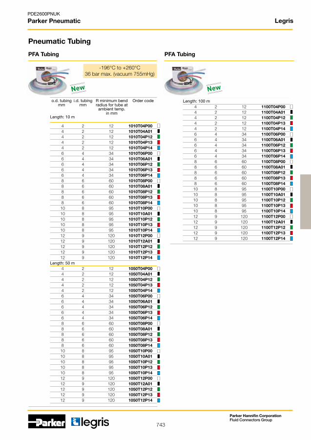
743
PDE2600PNUK
Parker Pneumatic
Parker Hannifin CorporationFluid Connectors Group
Legris
4 2 12 1010T04P00 4 2 12 1010T04A01 4 2 12 1010T04P12 4 2 12 1010T04P13 4 2 12 1010T04P14 6 4 34 1010T06P00 6 4 34 1010T06A01 6 4 34 1010T06P12 6 4 34 1010T06P13 6 4 34 1010T06P14 8 6 60 1010T08P00 8 6 60 1010T08A01 8 6 60 1010T08P12 8 6 60 1010T08P13 8 6 60 1010T08P14 10 8 95 1010T10P00 10 8 95 1010T10A01 10 8 95 1010T10P12 10 8 95 1010T10P13 10 8 95 1010T10P14 12 9 120 1010T12P00 12 9 120 1010T12A01 12 9 120 1010T12P12 12 9 120 1010T12P13 12 9 120 1010T12P14
4 2 12 1050T04P00 4 2 12 1050T04A01 4 2 12 1050T04P12 4 2 12 1050T04P13 4 2 12 1050T04P14 6 4 34 1050T06P00 6 4 34 1050T06A01 6 4 34 1050T06P12 6 4 34 1050T06P13 6 4 34 1050T06P14 8 6 60 1050T08P00 8 6 60 1050T08A01 8 6 60 1050T08P12 8 6 60 1050T08P13 8 6 60 1050T08P14 10 8 95 1050T10P00 10 8 95 1050T10A01 10 8 95 1050T10P12 10 8 95 1050T10P13 10 8 95 1050T10P14 12 9 120 1050T12P00 12 9 120 1050T12A01 12 9 120 1050T12P12 12 9 120 1050T12P13 12 9 120 1050T12P14
4 2 12 1100T04P00 4 2 12 1100T04A01 4 2 12 1100T04P12 4 2 12 1100T04P13 4 2 12 1100T04P14 6 4 34 1100T06P00 6 4 34 1100T06A01 6 4 34 1100T06P12 6 4 34 1100T06P13 6 4 34 1100T06P14 8 6 60 1100T08P00 8 6 60 1100T08A01 8 6 60 1100T08P12 8 6 60 1100T08P13 8 6 60 1100T08P14 10 8 95 1100T10P00 10 8 95 1100T10A01 10 8 95 1100T10P12 10 8 95 1100T10P13 10 8 95 1100T10P14 12 9 120 1100T12P00 12 9 120 1100T12A01 12 9 120 1100T12P12 12 9 120 1100T12P13 12 9 120 1100T12P14
PFA Tubing PFA Tubing
o.d. tubing i.d. tubing R minimum bend Order code mm mm radius for tube at ambient temp. in mm
Pneumatic Tubing
Length: 100 m
Length: 50 m
Length: 10 m
-196°C to +260°C 36barmax.(vacuum755mHg)
New New

744
PDE2600PNUK
Parker Pneumatic
Parker Hannifin CorporationFluid Connectors Group
Legris
8 5 1460U08 04
10 7 1460U10 04
12 8 1460U12 04
8 5 1461U08 04
10 7 1461U10 04
12 8 1461U12 04
8 5 1462U08 04
10 7 1462U10 04
12 8 1462U12 04
8 G1/4 0694 08 13
10 G1/4 0694 10 13
12 G3/8 0694 12 17
8 5 R1/4 1470U08 03 13 8 5 R1/4 1470U08 04 13 8 5 R1/4 1470U08 05 13
8 5 R1/4 1471U08 03 13 8 5 R1/4 1471U08 04 13 8 5 R1/4 1471U08 05 13
8 5 R1/4 1472U08 03 13 8 5 R1/4 1472U08 04 13 8 5 R1/4 1472U08 05 13
Pneumatic Tubing
1460U Polyurethane Recoil Tubing, without connectors, 2 m long
o.d. tubing i.d. tubing Order code mm mm
1461U Polyurethane Recoil Tubing, without connectors, 4 m long
o.d. tubing i.d. tubing Order code mm mm
1462U Polyurethane Recoil Tubing, without connectors, 6 m long
o.d. tubing i.d. tubing Order code mm mm
0694 Instant Fitting, with protection spring, BSPP
ØD C Order code
1470U Polyurethane Recoil Tubing, 2 m long, with Threaded Stem BSPT Thread
1471U Polyurethane Recoil Tubing, 4 m long, with Threaded Stem BSPT Thread
1472U Polyurethane Recoil Tubing, 6 m long, with Threaded Stem BSPT Thread
o.d. tubing i.d. tubing BSPT Order code mm mm thread
o.d. tubing i.d. tubing BSPT Order code mm mm thread
o.d. tubing i.d. tubing BSPT Order code mm mm thread
-20°C to +70°C 9 bar max.
4 2.5 40 1005T04 00 25 6 4 50 1005T06 00 8 6 70 1005T08 00 10 8 120 1005T10 00 12 10 180 1005T12 00
4 2.5 40 1025T04 00 25 6 4 50 1025T06 00 8 6 70 1025T08 00 10 8 120 1025T10 00 12 10 180 1025T12 00
1005T Fluoropolymer FEP 140 Tubing, 5m Rolls
o.d. tubing i.d. tubing R minimum bend Order code mm mm radius for tube at ambient temp. in mm
1025T Fluoropolymer FEP 140 Tubing, 25m Rolls
o.d. tubing i.d. tubing R minimum bend Order code mm mm radius for tube at ambient temp. in mm
-40°C to +150°C 37 bars max.
-40°C to +150°C 37 bar max.

745
PDE2600PNUK
Parker Pneumatic
Parker Hannifin CorporationFluid Connectors Group
8 4 10 1025V08 00 04
11 6 12 1025V11 00 06
13 7 14 1025V13 00 07
14 8 16 1025V14 00 08
16 10 25 1025V16 00 10
18 12 30 1025V18 00 12
23 15 40 1025V23 00 15
26 19 60 1025V26 00 19
1025V Braided PVC Hose, 25 m Rolls
o.d. tubing i.d. tubing R minimum Order code mm mm bend radius for tube at 20OC in mm
0° to +70°C15 bar
Legris
3000 71 00
3000 71 11
4 CLIP 04 00
6 CLIP 06 00
8 CLIP 08 00
10 CLIP 10 00
12 CLIP 12 00
14 CLIP 14 00
6 6.3 60 1040H56 02 6 6.3 60 1040H56 03 8 9.5 70 1040H60 02 8 9.5 70 1040H60 03 12 12.7 120 1040H62 02 12 12.7 120 1040H62 03 16 15.9 140 1040H66 02 16 15.9 140 1040H66 03 20 19.1 170 1040H69 02 20 19.1 170 1040H69 03
16 15.9 140 1080H66 02 16 15.9 140 1080H66 03 20 19.1 170 1080H69 02 20 19.1 170 1080H69 03
6 6.3 60 1100H56 02 6 6.3 60 1100H56 03 8 9.5 70 1100H60 02 8 9.5 70 1100H60 03 12 12.7 120 1100H62 02 12 12.7 120 1100H62 03
3000 Tube Cutter
Order code
Order code
3000 71 11 Tube Cutter
Clip Strips for Tubes
ØD Order code
Pneumatic Tubing
1040H Self-Fastening Hose, in 40m rolls
1080H Self-Fastening Hose, in 80m rolls
DN i.d. tubing R minimum bend Order code mm radius at 20°C (mm)
DN i.d. tubing R minimum bend Order code mm radius at 20°C (mm)
1100H Self-Fastening Hose, in 100m rolls
DN i.d. tubing R minimum bend Order code mm radius at 20°C (mm)
-20°C to +100°C 16 bar max.
-20°C to +100°C 16 bars max.
-20°C to +100°C 16 bar max.
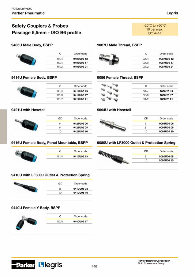
746
PDE2600PNUK
Parker Pneumatic
Parker Hannifin CorporationFluid Connectors Group
Legris
R1/4 9405U06 13
R3/4 9405U06 17
R1/2 9405U06 21
G1/4 9416U06 13
8 9410U06 08
10 9410U06 10
G3/8 9440U06 17
G1/4 9087U06 13
G1/8 9087U06 17
G1/2 9087U06 21
G1/4 9086 23 13
G3/8 9086 23 17
G1/2 9086 23 21
6 9094U06 06
8 9094U06 08
10 9094U06 10
8 9080U06 08
10 9080U06 10
G1/4 9414U06 13
G3/8 9414U06 17
G1/2 9414U06 21
6 9421U06 06
8 9421U06 08
10 9421U06 10
9405U Male Body, BSPP
Safety Couplers & Probes Passage 5,5mm - ISO B6 profile
C Order code
9416U Female Body, Panel Mountable, BSPP
9410U with LF3000 Outlet & Protection Spring
C Order code
ØD Order code
9440U Female Y Body, BSPP
9087U Male Thread, BSPP
C Order code
C Order code
9086 Female Thread, BSPP
9094U with Hosetail
C Order code
ØD Order code
9080U with LF3000 Outlet & Protection Spring
ØD Order code
9414U Female Body, BSPP
C Order code
9421U with Hosetail
ØD Order code
-20°C to +60°C 16 bar max.ISO4414
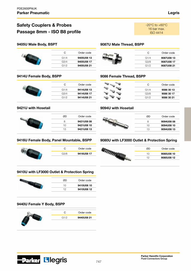
747
PDE2600PNUK
Parker Pneumatic
Parker Hannifin CorporationFluid Connectors Group
Legris
G1/4 9405U08 13
G3/4 9405U08 17
G1/2 9405U08 21
G3/8 9416U08 17
10 9410U08 10
12 9410U08 12
G1/2 9440U08 21
G1/4 9087U08 13
G3/8 9087U08 17
G1/2 9087U08 21
G1/4 9086 30 13
G3/8 9086 30 17
G1/2 9086 30 21
8 9094U08 08
10 9094U08 10
13 9094U08 13
10 9080U08 10
12 9080U08 12
G1/4 9414U08 13
G3/4 9414U08 17
G1/2 9414U08 21
8 9421U08 08
10 9421U08 10
13 9421U08 13
Safety Couplers & ProbesPassage 8mm - ISO B8 profile
9405U Male Body, BSPT
C Order code
9416U Female Body, Panel Mountable, BSPP
9410U with LF3000 Outlet & Protection Spring
C Order code
ØD Order code
9440U Female Y Body, BSPP
9087U Male Thread, BSPP
C Order code
C Order code
9086 Female Thread, BSPP
9094U with Hosetail
C Order code
ØD Order code
9080U with LF3000 Outlet & Protection Spring
ØD Order code
9414U Female Body, BSPP
C Order code
9421U with Hosetail
ØD Order code
-20°C to +60°C 16 bar max.ISO4414
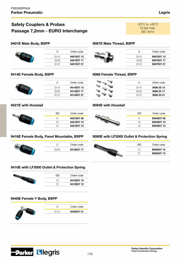
748
PDE2600PNUK
Parker Pneumatic
Parker Hannifin CorporationFluid Connectors Group
Legris
G1/4 9401E07 13
G3/8 9401E07 17
G1/2 9401E07 21
G3/8 9416E07 17
10 9410E07 10
12 9410E07 12
G1/2 9440E07 21
G1/4 9087E07 13
G3/8 9087E07 17
G1/2 9087E07 21
G1/4 9086 25 13
G3/8 9086 25 17
G1/2 9086 25 21
8 9094E07 08
10 9094E07 10
13 9094E07 13
10 9080E07 10
12 9080E07 12
G1/4 9414E07 13
G3/8 9414E07 17
G1/2 9414E07 21
8 9421E07 08
10 9421E07 10
13 9421E07 13
Safety Couplers & ProbesPassage 7,2mm - EURO Interchange
9401E Male Body, BSPP
C Order code
9416E Female Body, Panel Mountable, BSPP
9410E with LF3000 Outlet & Protection Spring
C Order code
ØD Order code
9440E Female Y Body, BSPP
9087E Male Thread, BSPP
C Order code
C Order code
9086 Female Thread, BSPP
9094E with Hosetail
C Order code
ØD Order code
9080E with LF3000 Outlet & Protection Spring
ØD Order code
9414E Female Body, BSPP
C Order code
9421E with Hosetail
ØD Order code
-20°C to +60°C 16 bar max.ISO4414

749
PDE2600PNUK
Parker Pneumatic
Parker Hannifin CorporationFluid Connectors Group
Legris
G1/4 9401A06 13
G3/8 9401A06 17
G1/2 9401A06 21
G1/4 9416A 06 13
8 9410A06 08
10 9410A06 10
G3/8 9440A06 17
G1/4 9087A06 13
G3/8 9087A06 17
G1/2 9087A06 21
G1/4 9086 22 13
G3/8 9086 22 17
G1/2 9086 22 21
6 9094A06 06
8 9094A06 08
10 9094A06 10
8 9080A06 08
10 9080A06 10
G1/4 9414A06 13
G3/8 9414A06 17
G1/2 9414A06 21
6 9421A06 06
8 9421A06 08
10 9421A06 10
Safety Couplers & Probes Passage 5,5mm - ARO Interchange
9401A Male Body, BSPP
C Order code
9416A Female Body, Panel Mountable, BSPP
9410A with LF3000 Outlet & Protection Spring
C Order code
ØD Order code
9440A Female Y Body, BSPP
9087A Male Thread, BSPP
C Order code
C Order code
9086 Female Thread, BSPP
9094A with Hosetail
C Order code
ØD Order code
9080A with LF3000 Outlet & Protection Spring
ØD Order code
9414A Female Body, BSPP
C Order code
9421A with Hosetail
ØD Order code
-20°C to +60°C 16 bar max.ISO4414

750
PDE2600PNUK
Parker Pneumatic
Parker Hannifin CorporationFluid Connectors Group
Legris
0659 00 13
0653 66 13
2.5 M12 x 1,25 0690 05 00
M12 x 1,25 0690 08 00
2.5 M12 x 1,25 0690 10 00
2.5 M12 x 1,25 0690 01 00
2.5 M12 x 1,25 0690 03 00
2 M12 x 1,25 0690 09 00
2 G1/4 0623 10 35
0656 66 13
0652 66 13
0654 00 13
0657 66 13
0655 66 13
G1/4
G1/4
G1/4
G1/4
G1/4
G1/4
G1/4
0659 Standard Blowgun, with angled nozzle, BSPP
0653 Flow Reducer «Energy Saving» Blowgun, lower connection
Blowguns & Nozzles
0690 Long-Angled Tube Nozzle
0690 Coenda Effect Nozzle
ØD C Order code
C Order code
0690 Booster Nozzle
ØD C Order code
0690 Standard Nozzle
0690 Long Straight Tube Nozzle
ØD C Order code
ØD C Order code
0690 Air Screen Nozzle
0623 Lever Operated Air Gun with Removable Nozzle
ØD C Order code
ØD C Order code
0656 Progressive Control, lower connection, BSPP
0652 Progressive Control, lower connection, BSPP
0654 Safety Blowgun, with angled nozzle, BSPP
0657 Progressive Control, upper connection, BSPP
0655 Progressive Control, upper connection, BSPP
-15°C to +50°C 10 bar max.OSHA&CE
C Order code
C Order code
C Order code
C Order code
C Order code
C Order code
C Order code
New
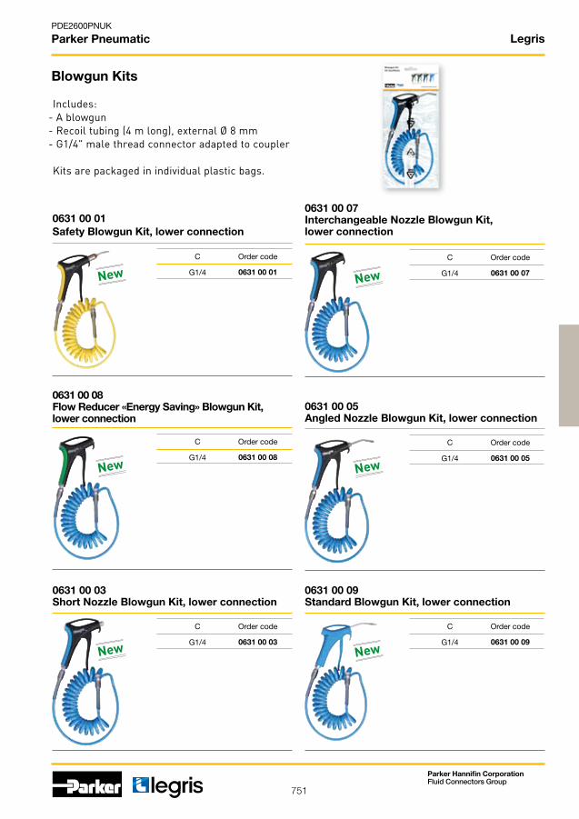
751
PDE2600PNUK
Parker Pneumatic
Parker Hannifin CorporationFluid Connectors Group
Legris
0631 00 01 0631 00 07
0631 00 08 0631 00 05
0631 00 03 0631 00 09
G1/4 G1/4
G1/4 G1/4
G1/4 G1/4
0631 00 01 Safety Blowgun Kit, lower connection
0631 00 07 Interchangeable Nozzle Blowgun Kit, lower connection
0631 00 08 Flow Reducer «Energy Saving» Blowgun Kit, lower connection
0631 00 05 Angled Nozzle Blowgun Kit, lower connection
0631 00 03 Short Nozzle Blowgun Kit, lower connection
0631 00 09 Standard Blowgun Kit, lower connection
Blowgun Kits
C Order code C Order code
C Order code C Order code
C Order code C Order code
New
New
New
New
New
New
Includes:- A blowgun- Recoil tubing (4 m long), external Ø 8 mm- G1/4" male thread connector adapted to coupler
Kits are packaged in individual plastic bags.

752
PDE2600PNUK
Parker Pneumatic
Parker Hannifin CorporationFluid Connectors Group
Legris
G1/4 10 30 4902 10 13 G3/8 10 30 4902 10 17 G1/2 15 30 4902 15 21 G3/4 20 30 4902 20 27 G2.1/2 25 30 4902 25 34 G2.1/2 32 25 4902 32 42G2.1/2 40 25 4902 40 49 G2.1/2 50 25 4902 50 48 G2.1/2 65 25 4902 65 47 G3” 80 25 4902 80 46 G4” 100 25 4902 01 45
G1/8 4 0402 04 10 G1/8 7 0402 07 10 G1/4 7 0402 07 13 G3/4 10 0402 10 17 G1/2 13 0402 13 21 G3/4 20 0402 20 27 G1” 23 0402 23 34
4 G1/8 0401 04 10 7 G1/4 0401 07 13 10 G3/8 0401 10 17 13 G1/2 0401 13 21 18 G3/4 0401 18 27 23 G1” 0401 23 34
6 G1/8 7911 06 10 8 G1/4 7911 08 13 10 G3/8 7911 10 17 12 G1/2 7911 12 21
6 G1/8 7914 06 10 8 G1/4 7914 08 13 10 G3/8 7914 10 17 12 G1/2 7914 12 21
4 7913 04 00 6 7913 06 00 8 7913 08 00 10 7913 10 00 12 7913 12 00
4 7910 04 00 6 7910 06 00 8 7910 08 00 10 7910 10 00 12 7910 12 00
G1/4 4 0491 04 13 G1/4 4 0491 04 13 64 G3/8 7 0491 07 17 G1/2 10 0491 10 21 G3/4 13 0491 13 27
G1/4 4 0492 04 13 G1/4 4 0492 04 13 64 G3/8 7 0492 07 17 G1/2 10 0492 10 21 G3/4 13 0492 13 27
Pneumatic Ball Valves & Action Valves
4902 In-Line Ball Valves, Fluoropolymer Series, BSPP
C DN PN Order code
-20° to +130°C30 bar
0402 Standard In-Line Ball Valve - Double Female, BSPP
C DN Order code
-20° to +80°C40 bar
0401 Standard In-Line Ball Valve, Male Female BSPP
ØD C Order code
-20° to +80°C40 bar
7911 Mini Ball Valves, 2/2 Version with BSPP thread & push-in connection
ØD C Order code
7914 Mini Ball Valves 3/2 version, with vent, with BSPP thread & push-in connection
ØD C Order code
7913 Mini Ball Valves, 3/2 version, with vent, with push-in connection
ØD Order code
7910 Mini Ball Valves, 2/2 version, with push-in connection
ØD Order code
0491 Male & Female, BSPP
C DN Order code
0492 Double Female
C DN Order code
-20° to +80°C12 bar
-20° to +80°C12 bar
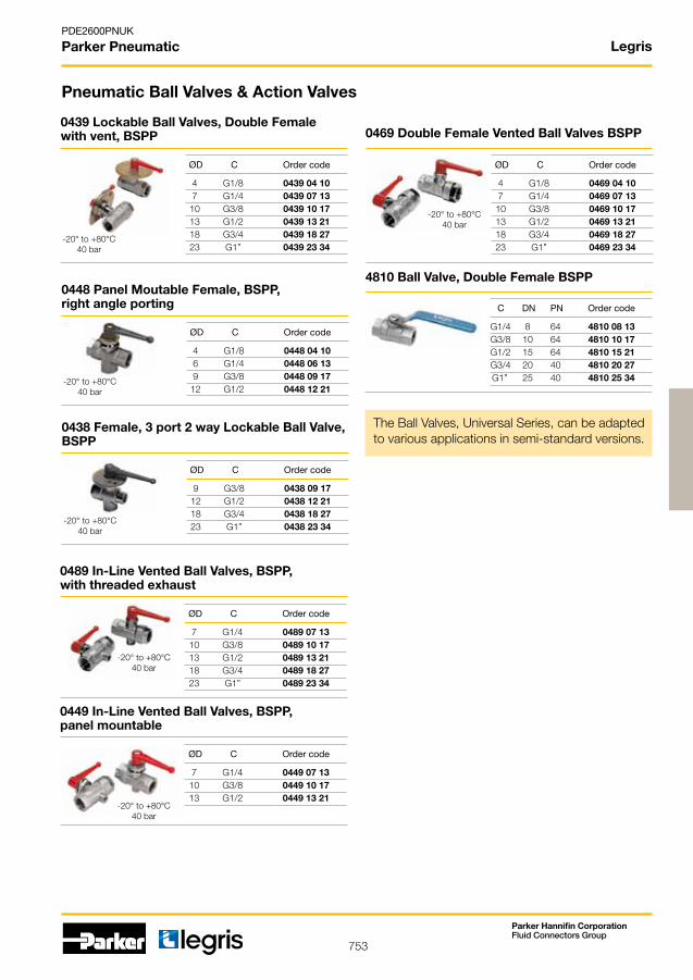
753
PDE2600PNUK
Parker Pneumatic
Parker Hannifin CorporationFluid Connectors Group
Legris
4 G1/8 0469 04 10 7 G1/4 0469 07 13 10 G3/8 0469 10 17 13 G1/2 0469 13 21 18 G3/4 0469 18 27 23 G1” 0469 23 34
G1/4 8 64 4810 08 13 G3/8 10 64 4810 10 17 G1/2 15 64 4810 15 21 G3/4 20 40 4810 20 27 G1” 25 40 4810 25 34
7 G1/4 0449 07 13 10 G3/8 0449 10 17 13 G1/2 0449 13 21
7 G1/4 0489 07 13 10 G3/8 0489 10 17 13 G1/2 0489 13 21 18 G3/4 0489 18 27 23 G1” 0489 23 34
4 G1/8 0448 04 10 6 G1/4 0448 06 13 9 G3/8 0448 09 17 12 G1/2 0448 12 21
9 G3/8 0438 09 17 12 G1/2 0438 12 21 18 G3/4 0438 18 27 23 G1” 0438 23 34
4 G1/8 0439 04 10 7 G1/4 0439 07 13 10 G3/8 0439 10 17 13 G1/2 0439 13 21 18 G3/4 0439 18 27 23 G1” 0439 23 34
Pneumatic Ball Valves & Action Valves
0469 Double Female Vented Ball Valves BSPP
The Ball Valves, Universal Series, can be adaptedto various applications in semi-standard versions.
ØD C Order code
-20° to +80°C40 bar
4810 Ball Valve, Double Female BSPP
C DN PN Order code
0449 In-Line Vented Ball Valves, BSPP, panel mountable
ØD C Order code
-20° to +80°C40 bar
0489 In-Line Vented Ball Valves, BSPP, with threaded exhaust
ØD C Order code
-20° to +80°C40 bar
0448 Panel Moutable Female, BSPP, right angle porting
ØD C Order code
-20° to +80°C40 bar
0438 Female, 3 port 2 way Lockable Ball Valve, BSPP
ØD C Order code
-20° to +80°C40 bar
0439 Lockable Ball Valves, Double Female with vent, BSPP
ØD C Order code
-20° to +80°C40 bar

754
PDE2600PNUK
Parker Pneumatic
Parker Hannifin CorporationFluid Connectors Group
Legris
10 G3/8 4222 10 17 20 15 G1/2 4222 15 21 20 20 G3/4 4222 20 27 20 25 G1” 4222 25 34 20 32 G1.1/4” 4222 32 42 20 40 G1.1/2” 4222 40 49 20 50 G2” 4222 50 48 20
24V 4298 01 01
24V 4298 01 02
110V 4298 02 01
220V 4298 02 02
G3/8 10 4202 10 17 20 G1/2 15 4202 15 21 20 G3/4 20 4202 20 27 20 G1” 25 4202 25 34 20 G1”1/4 32 4202 32 42 20 G1”1/2 40 4202 40 49 20 G2” 50 4202 50 48 20
G3/8 10 4212 10 17 20 G1/2 15 4212 15 21 20 G3/4 20 4212 20 27 20 G1” 25 4212 25 34 20 G1”1/4 32 4212 32 42 20 G1”1/2 40 4212 40 49 20 G2” 50 4212 50 48 20
M5 x 0.8 4298 00 01
M5 x 0.8 2 0669 02 19 G1/8 4 0669 04 10 G1/4 7 0669 07 13 G3/8 10 0669 10 17 G1/2 14 0669 14 21 G3/4 19 0669 19 27
4222 Axial Valve, double acting, double female, BSPP, FKM Seal
ØD C Order code
4298 Mini-Solenoid Valve, 1W/ 1,2VA
Voltage Order code
4202 Axial Valve, normally closed, double female, BSPP, FKM Seal
C DN Order code
4212 Axial Valve, normally open, double female, BSPP, FKM Seal
C DN Order code
4298 Namur Sub-Base for Solenoid Pilot Valve
C Order code
-20° to +135°C10 bar
-20° to +135°C8 bar
-20° to +135°C10 bar
0669 Sleeve Valve, Double Female, BSPP & M5
C DN Order code
Axial Valves

755
Parker Hannifin CorporationPneumatic Division - Europe
PDE2600PNUK
Parker Pneumatic
4 M5x,0,8 F8PMB4M5 30 6 M5x,0,8 F8PMB6M5 20 4 1/8 F4PMB4-1/8 20 4 1/4 F4PMB4-1/4 20 6 1/8 F4PMB6-1/8 30 6 1/4 F4PMB6-1/4 30 8 1/8 F4PB8-1/8 40 8 1/4 F4PB8-1/4 30 8 3/8 F4PB8-3/8 20 10 1/4 F4PB10-1/4 20 10 3/8 F4PB10-3/8 20 10 1/2 F4PB10-1/2 10 12 1/4 F4PB12-1/4 10 12 3/8 F4PB12-3/8 10 12 1/2 F4PB12-1/2 10 14 3/8 F4PB14-3/8 10 14 1/2 F4PB14-1/2 10
Operating information
• Usewithplasticormetaltubing
• Posititiveholdbyaflexiblegrabring
• Readytousefitting
• Plasticpushbutton
• Taperthreadfittingsforgeneraluse
• Parallelthreadfittingsforusewithplasticbodiedvalves
• Otherversionsavailable,refertoCD
Prestolok Micro
Working pressure 0,01 to 16 barWorking temperature -25 °C to +80 °C
Prestolok fittings are sold in packs. The package quantities are indicated adjacent to the part numbers.When ordering, order by the quantity required.Forexample:toobtain20Prestolok2EqualUnion4mmTees,purchase order should state:-
Qty 20 EPB4
NoteOrders received for Prestolok fittings in quantities other than pack quantity multiples will be rounded up to the nearest multiple
Ordering information
Male straight connectors - Parallel thread
Tube Thread Order code Box Qty Ø1 B
Male straight connectors
Tube Thread Order code Box Qty Ø1 B
4 M5x,0,8 F28PMB4M5 30 6 M5x,0,8 F28PMB6M5 20
Female connectors
Tube Thread Order code Box Qty Ø1 B
4 M5x0,8 G8PMB4M5 10 4 1/8 G4PMB4-1/8 20 4 1/4 G4PMB4-1/4 10 6 1/8 G4PMB6-1/8 20 6 1/4 G4PMB6-1/4 10 8 1/8 G4PB8-1/8 10 8 1/4 G4PB8-1/4 10
Tube Thread Order code Box Qty Ø1 A
4 1/8 F3PMB4-1/8 40 4 1/4 F3PMB4-1/4 30 6 1/8 F3PMB6-1/8 40 6 1/4 F3PMB6-1/4 40 8 1/8 F3PB8-1/8 40 8 1/4 F3PB8-1/4 40 8 3/8 F3PB8-3/8 30 10 1/4 F3PB10-1/4 20 10 3/8 F3PB10-3/8 20 10 1/2 F3PB10-1/2 10 12 1/4 F3PB12-1/4 10 12 3/8 F3PB12-3/8 10 12 1/2 F3PB12-1/2 10 14 3/8 F3PB14-3/8 10 14 1/2 F3PB14-1/2 10
Male Connector - BSPT
Prestolok 2
Working pressure 0,01 to 25 bar Working temperature -25 °C to +70 °C
Prestolok
Working pressure 0,01 to 25 barWorking temperature -25 °C to +100 °C
Prestolok Fittings
For more information see www.parker.com/euro_pneumatic

756
Parker Hannifin CorporationPneumatic Division - Europe
PDE2600PNUK
Parker Pneumatic
Tube Thread Plastic Box Qty Metal Box Qty Ø1 A Order code Order code
4 1/8 C63PMK4-1/8 30 C63PB4-1/8 20 4 1/4 C63PMK4-1/4 20 C63PB4-1/4 20 6 1/8 C63PMK6-1/8 20 C63PB6-1/8 20 6 1/4 C63PMK6-1/4 20 C63PB6-1/4 20 8 1/8 C63PK8-1/8 20 C63PB8-1/8 20 8 1/4 C63PK8-1/4 20 C63PB8-1/4 10 8 3/8 C63PK8-3/8 10 C63PB8-3/8 10 10 1/4 C63PK10-1/4 10 C63PB10-1/4 10 10 3/8 C63PK10-3/8 10 C63PB10-3/8 10 10 1/2 C63PK10-1/2 10 12 1/4 C63PK12-1/4 10 C63PB12-1/4 10 12 3/8 C63PK12-3/8 10 C63PB12-3/8 10 12 1/2 C63PK12-1/2 10 C63PB12-1/2 5 14 3/8 C63PK14-3/8 10 C63PB14-3/8 5 14 1/2 C63PK14-1/2 10 C63PB14-1/2 5
Adjustable male elbow - BSPT
Tube Thread Metal Box Qty Ø1 A Order code
4 1/8 C3PB4-1/8 20 6 1/8 C3PB6-1/8 10 6 1/4 C3PB6-1/4 10 8 1/8 C3PB8-1/8 10 8 1/4 C3PB8-1/4 10 10 1/4 C3PB10-1/4 10 10 3/8 C3PB10-3/8 10 12 3/8 C3PB12-3/8 5 12 1/2 C3PB12-1/2 5 14 3/8 C3PB14-3/8 5 14 1/2 C3PB14-1/2 5
Compact elbow - BSPT
Unequal union
Tube Tube Plastic Box Qty Ø1 Ø2 Order code
6 4 HPMK6-4 20 8 4 HPK8-4 20 8 6 HPK8-6 20 10 6 HPK10-6 10 10 8 HPK10-8 10 12 10 HPK12-10 10
Equal union
Tube Plastic Box Qty Metal Box Qty Ø1 Order code Order code
4 HPMK4 20 HPB4 30 6 HPMK6 30 HPB6 20 8 HPK8 30 HPB8 20 10 HPK10 20 HPB10 10 12 HPK12 10 HPB12 10 14 HPK14 10 HPB14 5
Tube Thread Metal (Micro) Box Qty Metal Box Qty Ø1 B Order code Order code
4 M11x0.75 WPMB4 10 WPB4 10 6 M13x1 WPMB6 10 WPB6 10 8 M15x1.25 WPB8 10 10 M18x1 WPB10 5 12 M23x1.5 WPB12 5 14 M24x1.5 WPB14 3
Bulkhead equal union
B
Prestolok Fittings

757
Parker Hannifin CorporationPneumatic Division - Europe
PDE2600PNUK
Parker Pneumatic
Equal union elbow
Tube Plastic Box Qty Metal Box Qty Ø1 Order code Order code
4 EPMK4 20 EPB4 20 6 EPMK6 20 EPB6 20 8 EPK8 20 EPB8 10 10 EPK10 10 EPB10 10 12 EPK12 10 EPB12 10 14 EPK14 10 EPB14 5
Tube Thread Plastic Box Qty Ø1 B Order code
4 1/8 C64LPMK4-1/8 10 4 1/4 C64LPMK4-1/4 10 6 1/8 C64LPMK6-1/8 10 6 1/4 C64LPMK6-1/4 10
Adjustable extended male elbow - Parallel
Tube Thread Plastic Box Qty Metal Box Qty Ø1 B Order code Order code
4 M5x0,8 C68SPK4M5 20 C68SPB4M5 10 4 1/8 C64SPK4-1/8 20 C64SPB4-1/8 10 4 1/4 C64SPK4-1/4 20 6 1/8 C64SPK6-1/8 20 C64SPB6-1/8 10 6 1/4 C64SPK6-1/4 20 C64SPB6-1/4 10 8 1/8 C64SPK8-1/8 20 C64SPB8-1/8 10 8 1/4 C64SPK8-1/4 20 C64SPB8-1/4 10 8 3/8 C64SPK8-3/8 10 C64SPB8-3/8 10 10 1/4 C64SPB10-1/4 10 10 3/8 C64SPB10-3/8 10 12 1/4 C64SPB12-1/4 10 12 3/8 C64SPB12-3/8 5 12 1/2 C64SPB12-1/2 5
Compact adjustable male elbow - Parallel
Compact plug in elbow
Tube Tube Plastic Box Qty Ø1 Ø2 Order code
4 4 T2ESPMK4 20 6 6 T2ESPMK6 20 4 6 T2ESPMK4-6 30 8 8 T2ESPK8 20
Equal union tee
Tube Plastic Box Qty Metal Box Qty Ø1 Order code Order code
4 JPMK4 20 JPB4 10 6 JPMK6 20 JPB6 10 8 JPK8 10 JPB8 10 10 JPK10 10 JPB10 10 12 JPK12 10 JPB12 5 14 JPK14 5 JPB14 5
Prestolok Fittings

758
Parker Hannifin CorporationPneumatic Division - Europe
PDE2600PNUK
Parker Pneumatic
Unequal union Y connector
Tube Tube Plastic Box Qty Ø1 Ø2 Order code
3 4 YJPMK4-3 10 3 6 YJPMK6-3 10 4 6 YJPMK6-4 10 6 8 YJPK6-6-8 10 8 10 YJPK8-8-10 5
Tube Thread Plastic Box Qty Metal Box Qty Ø1 B Order code Order code
4 M5x0,8 R68PMK4M5 10 R68PB4M5 10 6 M5x0,8 R68PMK6M5 10 R68PB6M5 10 4 1/8 R64PMK4-1/8 10 R64PB4-1/8 10 4 1/4 R64PMK4-1/4 10 R64PB4-1/4 10 6 1/8 R64PMK6-1/8 10 R64PB6-1/8 10 6 1/4 R64PMK6-1/4 10 R64PB6-1/4 10 8 1/8 R64PK8-1/8 10 R64PB8-1/8 10 8 1/4 R64PK8-1/4 10 R64PB8-1/4 10 8 3/8 R64PK8-3/8 10 R64PB8-3/8 10 10 1/4 R64PK10-1/4 10 R64PB10-1/4 5 10 3/8 R64PK10-3/8 5 R64PB10-3/8 5 12 1/4 R64PK12-1/4 5 R64PB12-1/4 5 12 3/8 R64PK12-3/8 5 R64PB12-3/8 5 14 3/8 R64PK14-3/8 5 R64PB14-3/8 3 14 1/2 R64PK14-1/2 5 R64PB14-1/2 3
Adjustable male run tee - Parallel
Tube Thread Plastic Box Qty Metal Box Qty Ø1 B Order code Order code
4 M3x0,5 S68PMK4M3 10 4 M5x0,8 S68PMK4M5 10 S68PB4M5 10 6 M5x0,8 S68PMK6M5 10 S68PB6M5 10 4 1/8 S64PMK4-1/8 10 S64PB4-1/8 10 4 1/4 S64PMK4-1/4 10 S64PB4-1/4 10 6 1/8 S64PMK6-1/8 10 S64PB6-1/8 10 6 1/4 S64PMK6-1/4 10 S64PB6-1/4 10 8 1/8 S64PK8-1/8 10 S64PB8-1/8 10 8 1/4 S64PK8-1/4 10 S64PB8-1/4 5 8 3/8 S64PK8-3/8 10 S64PB8-3/8 5 10 1/4 S64PK10-1/4 10 S64PB10-1/4 5 10 3/8 S64PK10-3/8 5 S64PB10-3/8 5 12 1/4 S64PK12-1/4 5 S64PB12-1/4 5 12 3/8 S64PK12-3/8 5 S64PB12-3/8 5 14 3/8 S64PK14-3/8 5 S64PB14-3/8 3 14 1/2 S64PK14-1/2 5 S64PB14-1/2 3
Adjustable male branch tee - Parallel
Unequal union tee
Tube Tube Plastic Box Qty Ø1 Ø2 Order code
6 4 JPK6-6-4 10 8 6 JPK8-8-6 10 10 8 JPK10-10-8 10 12 10 JPK12-12-10 10 4 6 JPK4-4-6 10 6 8 JPK6-6-8 10 8 10 JPK8-8-10 10 10 12 JPK10-10-12 5
Equal union Y connector
Tube Plastic Box Qty Ø1 Order code
4 YJPMK4 20 6 YJPMK6 10 8 YJPK8 10 10 YJPK10 10
1
Prestolok Fittings
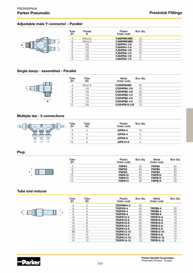
759
Parker Hannifin CorporationPneumatic Division - Europe
PDE2600PNUK
Parker Pneumatic
Tube Plastic Box Qty Metal Box Qty Ø1 Order code Order code
4 FNPK4 50 FNPB4 50 6 FNPK6 50 FNPB6 50 8 FNPK8 50 FNPB8 50 10 FNPK10 50 FNPB10 30 12 FNPK12 30 FNPB12 20 14 FNPK14 30 FNPB14 20
Plug
Tube Tube Metal Box Qty Ø1 Ø2 Order code
4 M5x0,8 COR8PB4M5 20 4 1/8 COR4PB4-1/8 10 6 1/8 COR4PB6-1/8 20 6 1/4 COR4PB6-1/4 20 8 1/8 COR4PB8-1/8 10 8 1/4 COR4PB8-1/4 20 10 3/8 COR4PB10-3/8 10
Single banjo - assembled - Parallel
Multiple tee - 5 connections
Tube Tube Plastic Box Qty Ø1 Ø2 Order code
6 4 J5PK6-4 10 8 4 J5PK8-4 5 8 6 J5PK8-6 5 10 6 J5PK10-6 5
Tube Thread Plastic Box Qty Ø1 B Order code
4 M5x0,8 YJ68PMK4M5 10 6 M5x0,8 YJ68PMK6M5 10 4 1/8 YJ64PK4-1/8 10 4 1/4 YJ64PK4-1/4 10 6 1/8 YJ64PK6-1/8 10 6 1/4 YJ64PK6-1/4 10 8 1/8 YJ64PK8-1/8 5 8 1/4 YJ64PK8-1/4 5
Adjustable male Y connector - Parallel
Tube Tube Plastic Box Qty Metal Box Qty Ø1 Ø2 Order code Order code
4 3 TR2PMK4-3 20 6 4 TR2PK6-4 40 TRPB6-4 20 8 4 TR2PK8-4 40 TRPB8-4 20 8 6 TR2PK8-6 30 TRPB8-6 10 10 4 TR2PK10-4 30 TRPB10-4 10 10 6 TR2PK10-6 30 TRPB10-6 10 10 8 TR2PK10-8 20 TRPB10-8 10 12 6 TR2PK12-6 20 TRPB12-6 10 12 8 TR2PK12-8 20 TRPB12-8 10 12 10 TR2PK12-10 10 TRPB12-10 10 14 8 TR2PK14-8 20 TRPB14-8 10 14 10 TR2PK14-10 10 TRPB14-10 10 14 12 TR2PK14-12 10 TRPB14-12 5
Tube end reducer
Prestolok Fittings
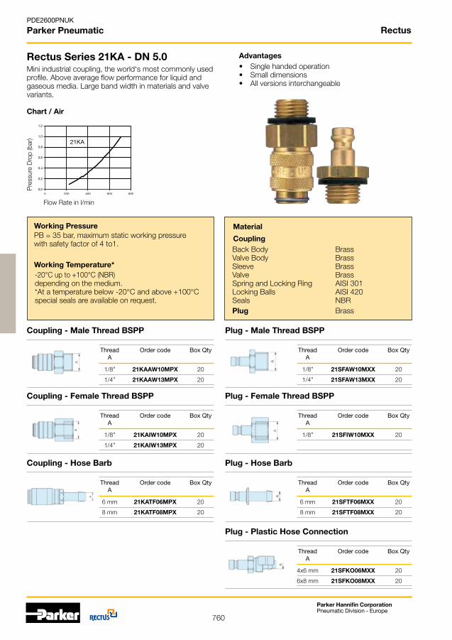
760
PDE2600PNUK
Parker Pneumatic
Parker Hannifin CorporationPneumatic Division - Europe
Rectus Series 21KA - DN 5.0
Coupling - Male Thread BSPP
Thread Order code Box Qty A
1/8” 21KAAW10MPX 20
1/4” 21KAAW13MPX 20
Plug - Male Thread BSPP
Working PressurePB = 35 bar, maximum static working pressure with safety factor of 4 to1.
Miniindustrialcoupling,theworld‘smostcommonlyusedprofile. Above average flow performance for liquid and gaseous media. Large band width in materials and valve variants.
Advantages• Single handed operation• Small dimensions • All versions interchangeable
Working Temperature*-20°C up to +100°C (NBR) depending on the medium.*At a temperature below -20°C and above +100°C special seals are available on request.
Back BodyValve BodySleeveValveSpring and Locking RingLocking BallsSealsPlug
Material
CouplingBrassBrassBrassBrassAISI 301AISI 420NBRBrass
Chart / Air
Pre
ssur
e D
rop
(bar
)
Flow Rate in l/min
Thread Order code Box Qty A
1/8” 21SFAW10MXX 20
1/4” 21SFAW13MXX 20
Coupling - Female Thread BSPP
Thread Order code Box Qty A
1/8” 21KAIW10MPX 20
1/4” 21KAIW13MPX 20
Plug - Female Thread BSPP
Thread Order code Box Qty A
1/8” 21SFIW10MXX 20
Rectus
Coupling - Hose Barb
Thread Order code Box Qty A
6 mm 21KATF06MPX 20
8 mm 21KATF08MPX 20
Plug - Hose Barb
Thread Order code Box Qty A
6 mm 21SFTF06MXX 20
8 mm 21SFTF08MXX 20
Plug - Plastic Hose Connection
Thread Order code Box Qty A
4x6 mm 21SFKO06MXX 20
6x8 mm 21SFKO08MXX 20

761
PDE2600PNUK
Parker Pneumatic
Parker Hannifin CorporationPneumatic Division - Europe
Rectus Series 17KA - DN 5.0
Coupling - Male Thread BSPT
Thread Order code Box Qty A
1/4” 17KAIW13SPN 10
1/2” 17KAIW21SPN 10
Plug - Male Thread BSPT
Working PressurePB = 35 bar, maximum static working pressure with safety factor of 4 to1.
English profile industrial coupling. Specially suited to compressed air applications. Brass/steel design developed for industry. Schrader (DN 5.0) Interchange.
Advantages• Single handed operation• Small dimensions, light weight• UltraFlo technology with high flow valve
Working Temperature*-20°C up to +100°C (NBR) depending on the medium.*At a temperature below -20°C and above +100°C special seals are available on request.
Back Body Valve BodySleeve Valve Inner Sleeve Spring PlateSpring and Locking RingLocking BallsSealsPlug
Material
Coupling
Brass, Nickel PlatedSteelHardened,ZincPl.SteelHardened,NickelPl.BrassBrassBrassAISI 303 AISI 420 NBRSteelHardened,NickelPl.
Chart / Air
Pre
ssur
e D
rop
(bar
)
Flow Rate in l/min
Thread Order code Box Qty A
1/8” 17SFAK10SXN 20
1/4” 17SFAK13SXN 20
Coupling - Female Thread BSPP Plug - Female Thread BSPP
Thread Order code Box Qty A
1/8” 17SFIW10SXN 20
1/4” 17SFIW13SXN 20
Thread Order code Box Qty A
1/4” 17KAAK13SPN 10
3/8” 17KAAK17SPN 10
1/2” 17KAAK21SPN 10
Rectus
Coupling - Hose Barb
Thread Order code Box Qty A
8 mm 17KATF08SPN 10
10 mm 17KATF10SPN 10
Plug - Hose Barb
Thread Order code Box Qty A
8 mm 17SFTF08SXN 20
10 mm 17SFTF10SXN 20

762
PDE2600PNUK
Parker Pneumatic
Parker Hannifin CorporationPneumatic Division - Europe
Rectus Series 18KA - DN 5.5
Coupling - Male Thread BSPT
Thread Order code Box Qty A
1/4” 18KAIW13MPN 5
3/8” 18KAIW17MPN 5
1/2” 18KAIW21MPN 5
Plug - Male Thread BSPT
Working PressurePB = 35 bar, maximum static working pressure with safety factor of 4 to1.
ISO6150CindustrialcouplingwithUltraFlotechnology.Robust design. The steel sleeve counters oscillating forces. System has limited use for liquids (steel sleeve/zinc die cast valve).
Advantages• Single handed operation• Plug design optimised through greater insert depth• Innovative valve technology with high flow valve
Working Temperature*-20°C up to +100°C (NBR) depending on the medium.*At a temperature below -20°C and above +100°C special seals are available on request.
Back BodyValve BodySleeveValveInner SleeveSpring PlateSpring / Locking RingLocking BallsSeals Plug
Material
Coupling
Brass, Nickel Plated Brass, Nickel Plated SteelHardened,NickelPl.Zinc Diecasting, Nickel Pl. Brass Brass AISI 301 AISI 420 NBRSteelHardened,NickelPl.
Chart / Air
Pre
ssur
e D
rop
(bar
)
Flow Rate in l/min
Thread Order code Box Qty A
1/4” 18SFAK13SXN 20
3/8” 18SFAK17SXN 5
Coupling - Female Thread BSPP Plug - Female Thread BSPP
Thread Order code Box Qty A
1/4” 18SFIW13SXN 20
3/8” 18SFIW17SXN 20
Thread Order code Box Qty A
1/4” 18KAAK13MPN 5
3/8” 18KAAK17MPN 5
Rectus
Coupling - Hose Barb
Thread Order code Box Qty A
8 mm 18KATF08MPN 5
10 mm 18KATF10MPN 5
Plug - Hose Barb
Thread Order code Box Qty A
6 mm 18SFTF06SXN 20
8 mm 18SFTF08SXN 20
10 mm 18SFTF10SXN 20
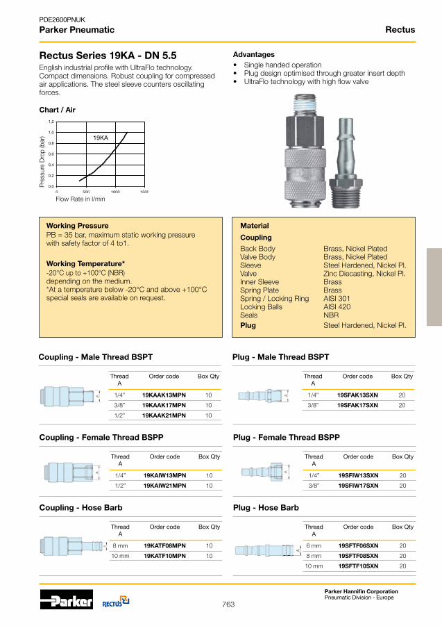
763
PDE2600PNUK
Parker Pneumatic
Parker Hannifin CorporationPneumatic Division - Europe
Rectus Series 19KA - DN 5.5
Coupling - Male Thread BSPT
Thread Order code Box Qty A
1/4” 19KAIW13MPN 10
1/2” 19KAIW21MPN 10
Plug - Male Thread BSPT
Working PressurePB = 35 bar, maximum static working pressure with safety factor of 4 to1.
English industrial profile with UltraFlo technology. Compact dimensions. Robust coupling for compressed air applications. The steel sleeve counters oscillating forces.
Advantages• Single handed operation• Plug design optimised through greater insert depth• UltraFlo technology with high flow valve
Working Temperature*-20°C up to +100°C (NBR) depending on the medium.*At a temperature below -20°C and above +100°C special seals are available on request.
Back BodyValve BodySleeveValveInner Sleeve Spring Plate Spring / Locking Ring Locking BallsSealsPlug
Material
Coupling
Brass, Nickel Plated Brass, Nickel Plated SteelHardened,NickelPl.Zinc Diecasting, Nickel Pl. Brass Brass AISI 301 AISI 420 NBRSteelHardened,NickelPl.
Chart / Air
Pre
ssur
e D
rop
(bar
)
Flow Rate in l/min
Thread Order code Box Qty A
1/4” 19SFAK13SXN 20
3/8” 19SFAK17SXN 20
Coupling - Female Thread BSPP Plug - Female Thread BSPP
Thread Order code Box Qty A
1/4” 19SFIW13SXN 20
3/8” 19SFIW17SXN 20
Thread Order code Box Qty A
1/4” 19KAAK13MPN 10
3/8” 19KAAK17MPN 10
1/2” 19KAAK21MPN 10
Rectus
Coupling - Hose Barb
Thread Order code Box Qty A
8 mm 19KATF08MPN 10
10 mm 19KATF10MPN 10
Plug - Hose Barb
Thread Order code Box Qty A
6 mm 19SFTF06SXN 20
8 mm 19SFTF08SXN 20
10 mm 19SFTF10SXN 20

764
PDE2600PNUK
Parker Pneumatic
Parker Hannifin CorporationPneumatic Division - Europe
Rectus Series 14KA - DN 5.5
Coupling - Male Thread BSPP
Thread Order code Box Qty A
1/4” 14KAIW13MPX 20
1/2” 14KAIW21MPX 20
Plug - Male Thread BSPT
Working PressurePB = 35 bar, maximum static working pressure with safety factor of 4 to1.
Robust brass coupling. Numerous connection options. Preferred application: compressed air technology and waterconnections.ARO210Interchangeable.
Advantages• Single handed operation• Optimisedplugdesignthroughgreaterinsertdepth
Working Temperature*-20°C up to +100°C (NBR) depending on the medium.*At a temperature below -20°C and above +100°C special seals are available on request.
Back BodyValve BodySleeve ValveSpring and Locking RingPinsSealsPlug
Material
Coupling
BrassBrassBrassBrassAISI 301
AISI 420NBRSteelHardened,Nickel Plated
Chart / Air
Pre
ssur
e D
rop
(bar
)
Flow Rate in l/min
Thread Order code Box Qty A
1/4” 22SFAK13SXN 20
3/8” 22SFAK17SXN 20
1/2” 22SFAK21SXN 10
Coupling - Female Thread BSPP Plug - Female Thread BSPP
Thread Order code Box Qty A
1/4” 22SFIW13SXN 20
3/8” 22SFIW17SXN 20
Thread Order code Box Qty A
1/4” 14KAAW13MPX 20
3/8” 14KAAW17MPX 20
1/2” 14KAAW21MPX 20
Rectus
Coupling - Hose Barb
Thread Order code Box Qty A
8 mm 14KATF08MPX 20
10 mm 14KATF10MPX 20
Plug - Hose Barb
Thread Order code Box Qty A
6 mm 22SFTF06SXN 20
8 mm 22SFTF08SXN 20
10 mm 22SFTF10SXN 20
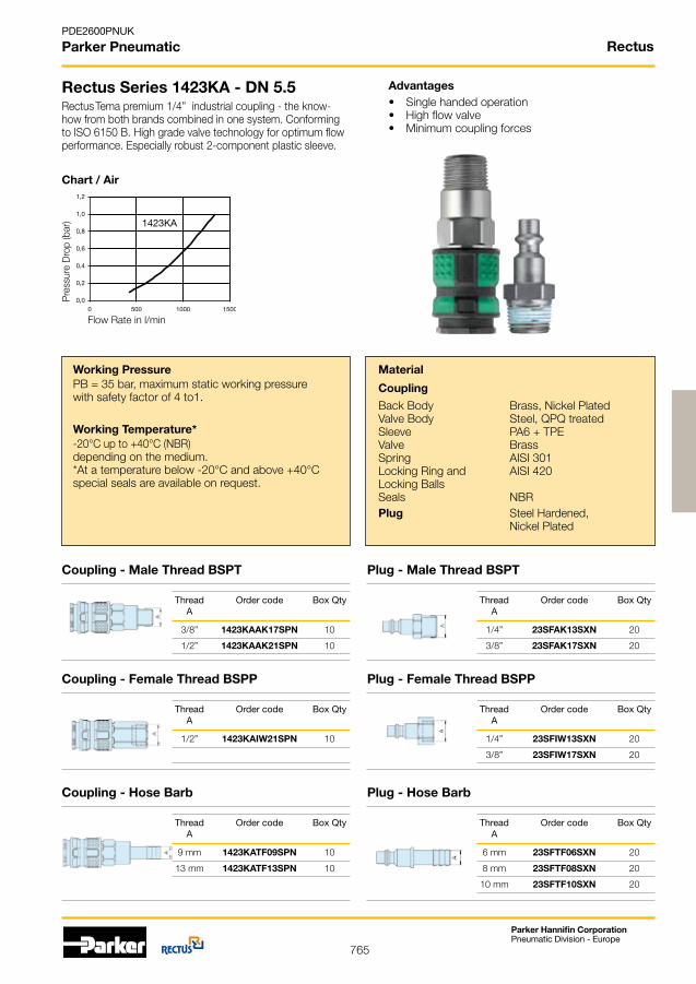
765
PDE2600PNUK
Parker Pneumatic
Parker Hannifin CorporationPneumatic Division - Europe
Rectus Series 1423KA - DN 5.5
Coupling - Male Thread BSPT
Thread Order code Box Qty A
3/8” 1423KAAK17SPN 10
1/2” 1423KAAK21SPN 10
Plug - Male Thread BSPT
Working PressurePB = 35 bar, maximum static working pressure with safety factor of 4 to1.
Rectus Tema premium 1/4” industrial coupling - the know-how from both brands combined in one system. Conforming toISO6150B.Highgradevalvetechnologyforoptimumflowperformance. Especially robust 2-component plastic sleeve.
Advantages• Single handed operation• Highflowvalve• Minimum coupling forces
Working Temperature*-20°C up to +40°C (NBR) depending on the medium.*At a temperature below -20°C and above +40°C special seals are available on request.
Back BodyValve BodySleeveValveSpringLocking Ring andLocking BallsSeals Plug
Material
Coupling
Brass, Nickel Plated Steel, QPQ treated PA6 + TPE BrassAISI 301 AISI 420
NBRSteelHardened, Nickel Plated
Chart / Air
Pre
ssur
e D
rop
(bar
)
Flow Rate in l/min
Thread Order code Box Qty A
1/4” 23SFAK13SXN 20
3/8” 23SFAK17SXN 20
Coupling - Female Thread BSPP
Thread Order code Box Qty A
1/2” 1423KAIW21SPN 10
Plug - Female Thread BSPP
Thread Order code Box Qty A
1/4” 23SFIW13SXN 20
3/8” 23SFIW17SXN 20
Rectus
Coupling - Hose Barb
Thread Order code Box Qty A
9 mm 1423KATF09SPN 10
13 mm 1423KATF13SPN 10
Plug - Hose Barb
Thread Order code Box Qty A
6 mm 23SFTF06SXN 20
8 mm 23SFTF08SXN 20
10 mm 23SFTF10SXN 20
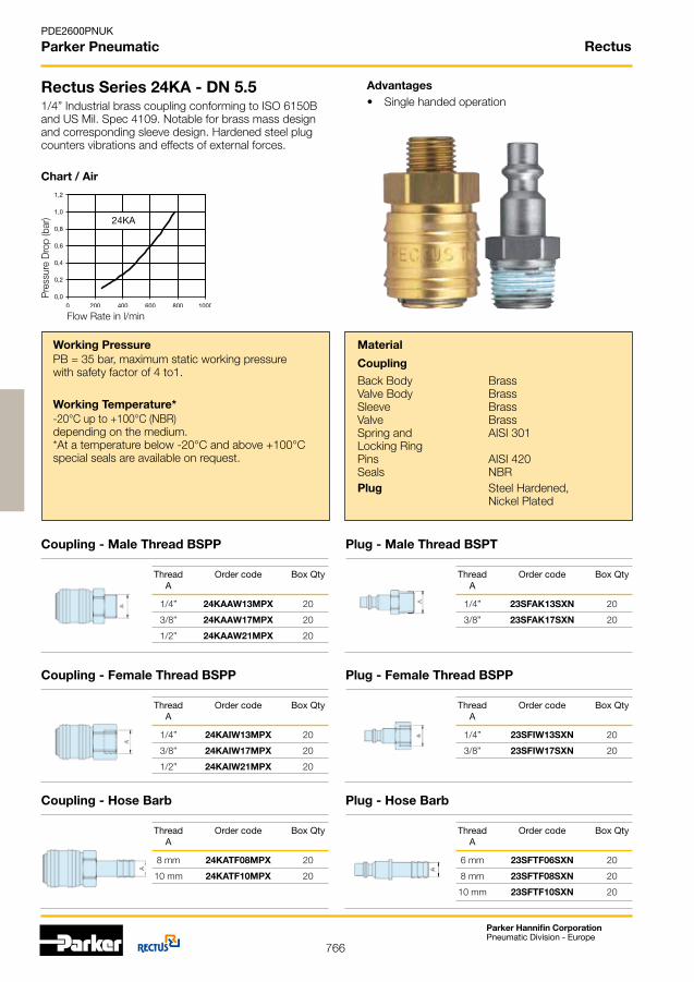
766
PDE2600PNUK
Parker Pneumatic
Parker Hannifin CorporationPneumatic Division - Europe
Rectus Series 24KA - DN 5.5
Coupling - Male Thread BSPP
Thread Order code Box Qty A
1/4” 24KAIW13MPX 20
3/8” 24KAIW17MPX 20
1/2” 24KAIW21MPX 20
Plug - Male Thread BSPT
Working PressurePB = 35 bar, maximum static working pressure with safety factor of 4 to1.
1/4”IndustrialbrasscouplingconformingtoISO6150Band US Mil. Spec 4109. Notable for brass mass design andcorrespondingsleevedesign.Hardenedsteelplugcounters vibrations and effects of external forces.
Advantages• Single handed operation
Working Temperature*-20°C up to +100°C (NBR) depending on the medium.*At a temperature below -20°C and above +100°C special seals are available on request.
Back BodyValve BodySleeveValveSpring and Locking RingPinsSealsPlug
Material
Coupling
BrassBrassBrassBrassAISI 301
AISI 420NBRSteelHardened, Nickel Plated
Chart / Air
Pre
ssur
e D
rop
(bar
)
Flow Rate in l/min
Thread Order code Box Qty A
1/4” 23SFAK13SXN 20
3/8” 23SFAK17SXN 20
Coupling - Female Thread BSPP Plug - Female Thread BSPP
Thread Order code Box Qty A
1/4” 23SFIW13SXN 20
3/8” 23SFIW17SXN 20
Thread Order code Box Qty A
1/4” 24KAAW13MPX 20
3/8” 24KAAW17MPX 20
1/2” 24KAAW21MPX 20
Rectus
Coupling - Hose Barb
Thread Order code Box Qty A
8 mm 24KATF08MPX 20
10 mm 24KATF10MPX 20
Plug - Hose Barb
Thread Order code Box Qty A
6 mm 23SFTF06SXN 20
8 mm 23SFTF08SXN 20
10 mm 23SFTF10SXN 20

767
PDE2600PNUK
Parker Pneumatic
Parker Hannifin CorporationPneumatic Division - Europe
Rectus Series 26KA - DN 7.2
Coupling - Male Thread BSPP
Thread Order code Box Qty A
1/4” 26KAAW13MPX 20
3/8” 26KAAW17MPX 20
1/2” 26KAAW21MPX 20
Plug - Male Thread BSPP
Working PressurePB = 35 bar, maximum static working pressure with safety factor of 4 to1.
European standard industrial profile. Universal brass coupling. Ergonomic sleeve design prevents dirt on the valve body. Series 26 plugs in brass. Series 25 steel plugs recommended for oscillating forces.
Advantages• Single handed operation• European standard• Small mass size
Working Temperature*-20°C up to +100°C (NBR) depending on the medium.*At a temperature below -20°C and above +100°C special seals are available on request.
Back BodyValve BodySleeveValveSpring and Locking RingLocking PinsSealsPlug
Material
Coupling
BrassBrassBrassBrassAISI 301AISI 420NBRBrass
Chart / Air
Pre
ssur
e D
rop
(bar
)
Flow Rate in l/min
Thread Order code Box Qty A
1/4” 26SFAW13MXX 20
3/8” 26SFAW17MXX 20
Coupling - Female Thread BSPP
Thread Order code Box Qty A
1/4” 26KAIW13MPX 20
1/2” 26KAIW21MPX 20
Plug - Female Thread BSPP
Thread Order code Box Qty A
1/4” 26SFIW13MXX 20
3/8” 26SFIW17MXX 20
Rectus
Coupling - Hose Barb
Thread Order code Box Qty A
6 mm 26KATF06MPX 20
8 mm 26KATF08MPX 20
9 mm 26KATF09MPX 20
Plug - Hose Barb
Thread Order code Box Qty A
6 mm 26SFTF06MXX 20
8 mm 26SFTF08MXX 20
9 mm 26SFTF09MXX 20
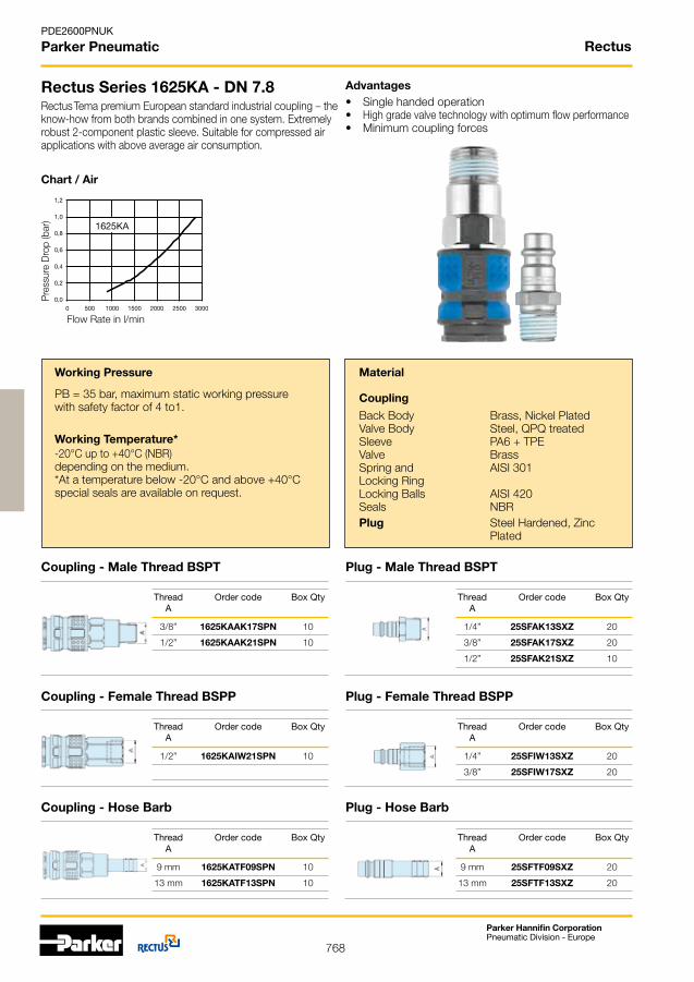
768
PDE2600PNUK
Parker Pneumatic
Parker Hannifin CorporationPneumatic Division - Europe
Rectus Series 1625KA - DN 7.8
Coupling - Male Thread BSPT
Thread Order code Box Qty A
1/2” 1625KAIW21SPN 10
Working Pressure
PB = 35 bar, maximum static working pressure with safety factor of 4 to1.
Rectus Tema premium European standard industrial coupling – the know-how from both brands combined in one system. Extremely robust 2-component plastic sleeve. Suitable for compressed air applications with above average air consumption.
Advantages• Single handed operation• Highgradevalvetechnologywithoptimumflowperformance• Minimum coupling forces
Working Temperature*-20°C up to +40°C (NBR) depending on the medium.*At a temperature below -20°C and above +40°C special seals are available on request.
Back BodyValve BodySleeveValveSpring andLocking RingLocking BallsSeals Plug
Material
Coupling
Brass, Nickel Plated Steel, QPQ treated PA6 + TPE BrassAISI 301 AISI 420NBRSteelHardened, Zinc Plated
Chart / Air
Pre
ssur
e D
rop
(bar
)
Flow Rate in l/min
Coupling - Female Thread BSPP
Thread Order code Box Qty A
3/8” 1625KAAK17SPN 10
1/2” 1625KAAK21SPN 10
Plug - Male Thread BSPT
Thread Order code Box Qty A
1/4” 25SFAK13SXZ 20
3/8” 25SFAK17SXZ 20
1/2” 25SFAK21SXZ 10
Plug - Female Thread BSPP
Thread Order code Box Qty A
1/4” 25SFIW13SXZ 20
3/8” 25SFIW17SXZ 20
Rectus
Coupling - Hose Barb
Thread Order code Box Qty A
9 mm 1625KATF09SPN 10
13 mm 1625KATF13SPN 10
Plug - Hose Barb
Thread Order code Box Qty A
9 mm 25SFTF09SXZ 20
13 mm 25SFTF13SXZ 20
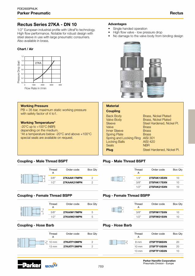
769
PDE2600PNUK
Parker Pneumatic
Parker Hannifin CorporationPneumatic Division - Europe
Rectus Series 27KA - DN 10
Coupling - Male Thread BSPT
Thread Order code Box Qty A
3/8” 27KAIW17MPN 5
1/2” 27KAIW21MPN 5
Plug - Male Thread BSPT
Working PressurePB = 35 bar, maximum static working pressure with safety factor of 4 to1.
1/2” European industrial profile with UltraFlo technology. Highflowperformance.Notableforrobustdesignwithsteel sleeve in use with large pneumatic consumers. Also available in brass.
Advantages• Single handed operation• Highflowvalve-lowpressuredrop• No damage to the valve body from binding design
Working Temperature*-20°C up to +100°C (NBR) depending on the medium.*At a temperature below -20°C and above +100°C special seals are available on request.
Back BodyValve BodySleeveValveInner SleeveSpring PlateSpring and Locking RingLocking BallsSeals Plug
Material
Coupling
Brass, Nickel PlatedBrass, Nickel PlatedSteelHardened,NickelPl.BrassBrassBrassAISI 301AISI 420NBRSteelHardened, Nickel Pl.
Chart / Air
Pre
ssur
e D
rop
(bar
)
Flow Rate in l/min
Thread Order code Box Qty A
1/4” 27SFAK13SXN 10
3/8” 27SFAK17SXN 10
1/2” 27SFAK21SXN 10
Coupling - Female Thread BSPP Plug - Female Thread BSPP
Thread Order code Box Qty A
3/8” 27SFIW17SXN 10
1/2” 27SFIW21SXN 10
Thread Order code Box Qty A
3/8” 27KAAK17MPN 2
1/2” 27KAAK21MPN 2
Rectus
Plug - Hose Barb
Thread Order code Box Qty A
8 mm 27SFTF08SXN 20
10 mm 27SFTF10SXN 20
13 mm 27SFTF13SXN 10
Coupling - Hose Barb
Thread Order code Box Qty A
10 mm 27KATF10MPN 2
13 mm 27KATF13MPN 2
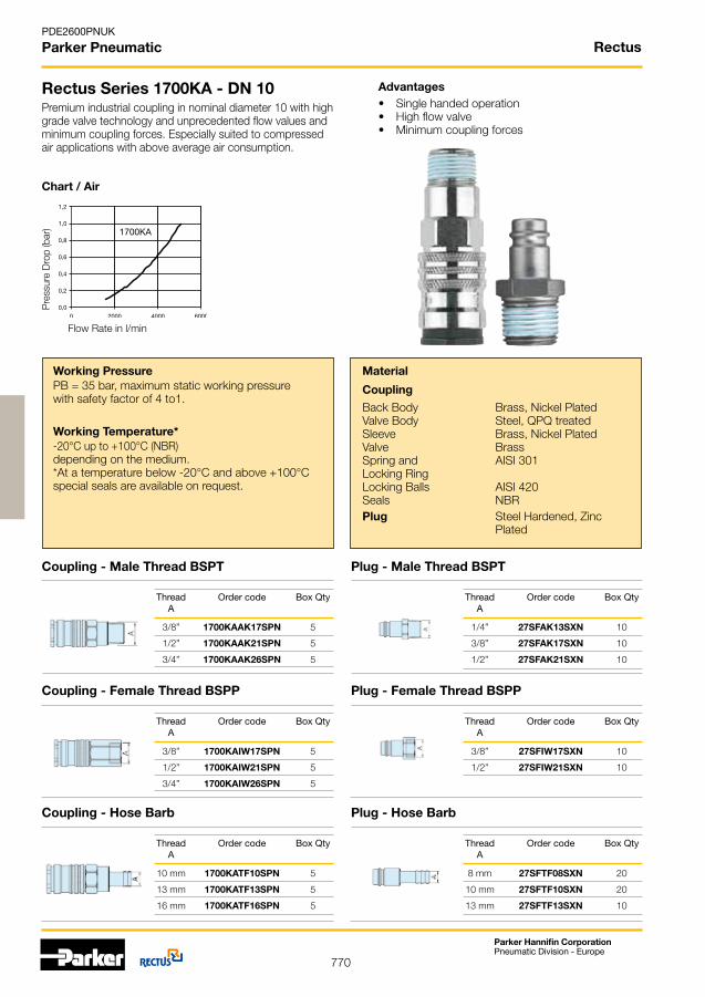
770
PDE2600PNUK
Parker Pneumatic
Parker Hannifin CorporationPneumatic Division - Europe
Rectus Series 1700KA - DN 10
Coupling - Male Thread BSPT
Thread Order code Box Qty A
3/8” 1700KAIW17SPN 5
1/2” 1700KAIW21SPN 5
3/4” 1700KAIW26SPN 5
Plug - Male Thread BSPT
Working PressurePB = 35 bar, maximum static working pressure with safety factor of 4 to1.
Premium industrial coupling in nominal diameter 10 with high grade valve technology and unprecedented flow values and minimum coupling forces. Especially suited to compressed air applications with above average air consumption.
Advantages• Single handed operation• Highflowvalve• Minimum coupling forces
Working Temperature*-20°C up to +100°C (NBR) depending on the medium.*At a temperature below -20°C and above +100°C special seals are available on request.
Back BodyValve BodySleeveValveSpring andLocking RingLocking BallsSeals Plug
Material
Coupling
Brass, Nickel Plated Steel, QPQ treated Brass, Nickel Plated BrassAISI 301
AISI 420 NBRSteelHardened, Zinc Plated
Chart / Air
Pre
ssur
e D
rop
(bar
)
Flow Rate in l/min
Thread Order code Box Qty A
1/4” 27SFAK13SXN 10
3/8” 27SFAK17SXN 10
1/2” 27SFAK21SXN 10
Coupling - Female Thread BSPP Plug - Female Thread BSPP
Thread Order code Box Qty A
3/8” 27SFIW17SXN 10
1/2” 27SFIW21SXN 10
Thread Order code Box Qty A
3/8” 1700KAAK17SPN 5
1/2” 1700KAAK21SPN 5
3/4” 1700KAAK26SPN 5
Rectus
Plug - Hose Barb
Thread Order code Box Qty A
8 mm 27SFTF08SXN 20
10 mm 27SFTF10SXN 20
13 mm 27SFTF13SXN 10
Coupling - Hose Barb
Thread Order code Box Qty A
10 mm 1700KATF10SPN 5
13 mm 1700KATF13SPN 5
16 mm 1700KATF16SPN 5

771
PDE2600PNUK
Parker Pneumatic
Parker Hannifin CorporationPneumatic Division - Europe
Rectus Series 37KA - DN 11
Coupling - Male Thread BSPP
Thread Order code Box Qty A
3/8” 37KAIW17MPX 2
1/2” 37KAIW21MPX 2
3/4” 37KAIW26MPX 2
Plug - Male Thread BSPT
Working PressurePB = 35 bar, maximum static working pressure with safety factor of 4 to1.
1/2” Coupling-system according to US-MIL-Spec. C-4109 made of brass. Plug design optimised through greater insert depth.
Advantages• Single handed operation• Tough construction
Working Temperature*-20°C up to +100°C (NBR) depending on the medium.*At a temperature below -20°C and above +100°C special seals are available on request.
Back BodyValve BodySleeveValveSpring and Locking RingLocking Balls Seals Plug
Material
Coupling
BrassBrassBrassBrassAISI 301
AISI 420NBRSteelHardened, Nickel Plated
Chart / Air
Pre
ssur
e D
rop
(bar
)
Flow Rate in l/min
Thread Order code Box Qty A
1/2” 37SFAK21SXN 10
3/4” 37SFAK26SXN 5
Coupling - Female Thread BSPP Plug - Female Thread BSPP
Thread Order code Box Qty A
1/2” 37SFIW21SXN 5
3/4” 37SFIW26SXN 5
Thread Order code Box Qty A
3/8” 37KAAW17MPX 2
1/2” 37KAAW21MPX 2
3/4” 37KAAW26MPX 2
Rectus
Plug - Hose Barb
Thread Order code Box Qty A
13 mm 37SFTF13SXN 10
16 mm 37SFTF16SXN 10
19 mm 37SFTF19SXN 5

772
PDE2600PNUK
Parker Pneumatic
Parker Hannifin CorporationPneumatic Division - Europe
Rectus Self-Venting Series 14KE - DN 5.5
Coupling - Male Thread BSPT
Working PressurePB = 12 bar, maximum static working pressure with safety factor of 4 to1.
The connection is made the same way as with all other quick connect coupling series, by simply pushing the plug in the coupling. The audible latching when the plug is securely in place signifies that the coupling is locked. The sleeve must be pulled back to release the first locking system before it can be disconnected. This closes the coupling valve. The compressed downstream air can now escape from the plug (hose). Pulling the sleeve back a second time releases the second locking system. The connection can now be safely undone. This self-venting coupling, designed for bleeding off trapped air, is not suitable for direct connection to compressed air tools.
AdvantagesThesystemfulfilstherequirementsofISO4414• increased safety standards in the work place• the plastic sleeve does not scratch working surfaces
Working Temperature*-20°C up to +60°C (NBR) depending on the medium.*At a temperature below -20°C and above +60°C special seals are available on request.
Back BodyValve BodySleeveValveSpringLocking BallsSealsPinsPlug
Material
Coupling
Brass, Nickel PlatedBrass, Nickel PlatedThermoplasticBrassAISI 301AISI 420NBRAISI 420SteelHardened, Nickel Pl.
Chart / Air
Pre
ssur
e D
rop
(bar
)
Flow Rate in l/min
Thread Order code Box Qty A
1/4” 14KEAK13MPN 10
1/2” 14KEAK21MPN 10
Plug - Male Thread BSPT Thread Order code Box Qty A
1/4” 22SFAK13SXN 20
3/8” 22SFAK17SXN 20
1/2” 22SFAK21SXN 10
Self-Venting System
CautionNot recommended for direct connection to compressed air tools. Reliable functioning can only be guaranteed in conjunctionwithoriginalRectus plugs made of steel.
Rectus
Thread Order code Box Qty A
1/4” 14KEIW13MPN 10
1/2” 14KEIW21MPN 10
Coupling - Female Thread BSPP Plug - Female Thread BSPP
Thread Order code Box Qty A
1/4” 22SFIW13SXN 20
3/8” 22SFIW17SXN 20
Plug - Hose Barb
Thread Order code Box Qty A
6 mm 22SFTF06SXN 20
8 mm 22SFTF08SXN 20
10 mm 22SFTF10SXN 20
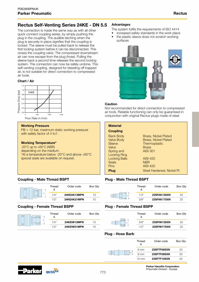
773
PDE2600PNUK
Parker Pneumatic
Parker Hannifin CorporationPneumatic Division - Europe
Rectus Self-Venting Series 24KE - DN 5.5
Coupling - Male Thread BSPT Plug - Male Thread BSPT
Working PressurePB = 12 bar, maximum static working pressure with safety factor of 4 to1.
The connection is made the same way as with all other quick connect coupling series, by simply pushing the plug in the coupling. The audible latching when the plug is securely in place signifies that the coupling is locked. The sleeve must be pulled back to release the first locking system before it can be disconnected. This closes the coupling valve. The compressed downstream air can now escape from the plug (hose). Pulling the sleeve back a second time releases the second locking system. The connection can now be safely undone. This self-venting coupling, designed for bleeding off trapped air, is not suitable for direct connection to compressed air tools.
AdvantagesThesystemfulfilstherequirementsofISO4414• increased safety standards in the work place• the plastic sleeve does not scratch working surfaces
Working Temperature*-20°C up to +60°C (NBR) depending on the medium.*At a temperature below -20°C and above +60°C special seals are available on request.
Back BodyValve BodySleeveValveSpring and Locking RingLocking BallsSealsPinsPlug
Material
Coupling
Brass, Nickel PlatedBrass, Nickel PlatedThermoplasticBrassAISI 301
AISI 420NBRAISI 420SteelHardened, Nickel Pl.
Chart / Air
Pre
ssur
e D
rop
(bar
)
Flow Rate in l/min
Thread Order code Box Qty A
1/4” 23SFAK13SXN 20
3/8” 23SFAK17SXN 20
Thread Order code Box Qty A
1/4” 24KEAK13MPN 10
1/2” 24KEAK21MPN 10
Self-Venting System
CautionNot recommended for direct connection to compressed air tools. Reliable functioning can only be guaranteed in conjunctionwithoriginalRectus plugs made of steel.
Rectus
Thread Order code Box Qty A
1/4” 24KEIW13MPN 10
1/2” 24KEIW21MPN 10
Coupling - Female Thread BSPP Plug - Female Thread BSPP
Thread Order code Box Qty A
3/8” 23SFIW13SXN 20
1/2” 23SFIW17SXN 20
Plug - Hose Barb
Thread Order code Box Qty A
6 mm 23SFTF06SXN 20
8 mm 23SFTF08SXN 20
10 mm 23SFTF10SXN 20
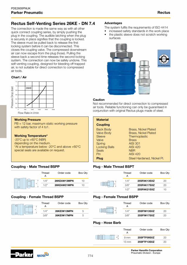
774
PDE2600PNUK
Parker Pneumatic
Parker Hannifin CorporationPneumatic Division - Europe
Rectus Self-Venting Series 26KE - DN 7.4
Coupling - Male Thread BSPP Plug - Male Thread BSPT
Working PressurePB = 12 bar, maximum static working pressure with safety factor of 4 to1.
The connection is made the same way as with all other quick connect coupling series, by simply pushing the plug in the coupling. The audible latching when the plug is securely in place signifies that the coupling is locked. The sleeve must be pulled back to release the first locking system before it can be disconnected. This closes the coupling valve. The compressed downstream air can now escape from the plug (hose). Pulling the sleeve back a second time releases the second locking system. The connection can now be safely undone. This self-venting coupling, designed for bleeding off trapped air, is not suitable for direct connection to compressed air tools.
AdvantagesThesystemfulfilstherequirementsofISO4414• increased safety standards in the work place• the plastic sleeve does not scratch working surfaces
Working Temperature*-20°C up to +60°C (NBR) depending on the medium.*At a temperature below -20°C and above +60°C special seals are available on request.
Back BodyValve BodySleeveValveSpringLocking BallsSealsPin Plug
Material
Coupling
Brass, Nickel PlatedBrass, Nickel PlatedThermoplasticBrassAISI 301AISI 420NBRAISI 420SteelHardened, Nickel Pl.
Chart / Air
Pre
ssur
e D
rop
(bar
)
Flow Rate in l/min
Thread Order code Box Qty A
1/4” 25SFAK13SXZ 20
3/8” 25SFAK17SXZ 20
1/2” 25SFAK21SXZ 10
Thread Order code Box Qty A
1/4” 26KEAW13MPN 10
1/2” 26KEAW21MPN 10
Self-Venting System
CautionNot recommended for direct connection to compressed air tools. Reliable functioning can only be guaranteed in conjunctionwithoriginalRectus plugs made of steel.
Rectus
Thread Order code Box Qty A
1/4” 26KEIW13MPN 5
3/8” 26KEIW17MPN 5
Coupling - Female Thread BSPP Plug - Female Thread BSPP
Thread Order code Box Qty A
1/4” 25SFIW13SXZ 20
3/8” 25SFIW17SXZ 20
Plug - Hose Barb
Thread Order code Box Qty A
9 mm 25SFTF09SXZ 20
13 mm 25SFTF13SXZ 20
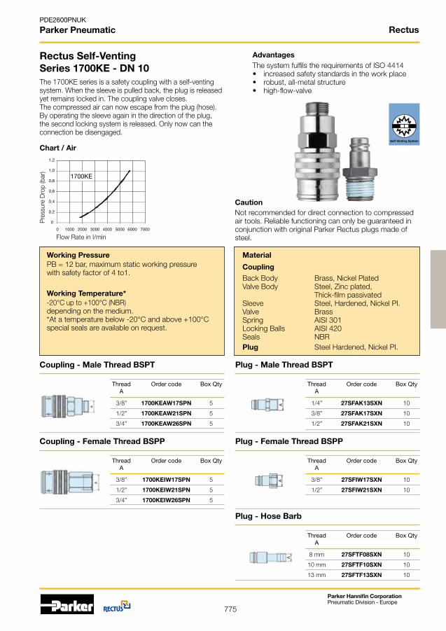
775
PDE2600PNUK
Parker Pneumatic
Parker Hannifin CorporationPneumatic Division - Europe
Rectus
0
0,2
0,4
0,6
0,8
1,0
1,2
0 1000 2000 3000 4000 5000 6000 7000
1700KE
Rectus Self-VentingSeries 1700KE - DN 10
Coupling - Male Thread BSPT
Thread Order code Box Qty A
3/8” 1700KEIW17SPN 5
1/2” 1700KEIW21SPN 5
3/4” 1700KEIW26SPN 5
Plug - Male Thread BSPT
Working PressurePB = 12 bar, maximum static working pressure with safety factor of 4 to1.
The 1700KE series is a safety coupling with a self-venting system. When the sleeve is pulled back, the plug is released yet remains locked in. The coupling valve closes.The compressed air can now escape from the plug (hose). By operating the sleeve again in the direction of the plug, thesecondlockingsystemisreleased.Onlynowcantheconnection be disengaged.
AdvantagesThesystemfulfilstherequirementsofISO4414• increased safety standards in the work place• robust, all-metal structure• high-flow-valve
Working Temperature*-20°C up to +100°C (NBR) depending on the medium.*At a temperature below -20°C and above +100°C special seals are available on request.
Back BodyValve Body
SleeveValveSpring Locking BallsSeals Plug
Material
Coupling
Brass, Nickel Plated Steel, Zinc plated,Thick-film passivated Steel,Hardened,NickelPI. BrassAISI 301AISI 420NBRSteelHardened, Nickel PI.
Chart / Air
Pre
ssur
e D
rop
(bar
)
Flow Rate in l/min
Thread Order code Box Qty A
1/4” 27SFAK13SXN 10
3/8” 27SFAK17SXN 10
1/2” 27SFAK21SXN 10
Coupling - Female Thread BSPP Plug - Female Thread BSPP
Thread Order code Box Qty A
3/8” 27SFIW17SXN 10
1/2” 27SFIW21SXN 10
Thread Order code Box Qty A
3/8” 1700KEAW17SPN 5
1/2” 1700KEAW21SPN 5
3/4” 1700KEAW26SPN 5
Plug - Hose Barb
Thread Order code Box Qty A
8 mm 27SFTF08SXN 10
10 mm 27SFTF10SXN 10
13 mm 27SFTF13SXN 10
Self-Venting System
Not recommended for direct connection to compressed air tools. Reliable functioning can only be guaranteed in conjunctionwithoriginalParkerRectus plugs made of steel.
Caution

776
PDE2600PNUK
Parker Pneumatic
Parker Hannifin CorporationPneumatic Division - Europe
Blow Guns
Plastic - with Aluminium Extension Nozzle
Thread Order code Box Qty
26SF AK26SF 20
Aluminium with Standard Nozzle
Thread Order code Box Qty
1/4” AA13 20
Plastic, Aluminium Nozzle, Plug 26SF Series Aluminium, Standard Nozzle, Plug 26SF Series
Thread Order code Box Qty
26SF AA26SF 20
Thread Order code Box Qty
1/4” AK13 20
Hose Tail Barb, Brass
Male Thread
Connection Order code Box Qty
G 1/4, 8 mm GT13/08 20
G 3/8, 13 mm GT17/13 20
G 1/2, 9 mm GT21/09 20
G 1/2, 13 mm GT21/13 20
3 Way Manifold Assembly
Brass, with Coulings 26KA Series
Connection Order code Box Qty
G 1/4 i. DM13I 20
G 3/8 i. DM17I 20
G 1/2 i. DM21I 20
PA12 Tubing
26 Series Coupling and Plug with Spring Guard
Connection Length Order code Box Qty /mm
6,3 x 7,9 5,0 m SP08/050/K+S 1
9,5 x 11,8 7,5 m SP12/075/K+S 1
PU Tubing
with Straight Extensions 508 mm and 127 mm
Connection Length Order code Box Qty /mm
6,3 x 9,5 6,0 m PU10/060/DV 1
8,0 x 12,0 7,5 m PU12/075/DV 1
Rectus

777
Parker Hannifin CorporationPneumatic Division - Europe
PDE2600PNUK
Parker Pneumatic

778
Parker Hannifin CorporationPneumatic Division - Europe
PDE2600PNUK
Parker Pneumatic Parker’s Motion & Control Technologies
AEROSPACEKey Markets•Aircraftengines•Business&generalaviation•Commercialtransports•Land-basedweaponssystems•Militaryaircraft•Missiles&launchvehicles•Regionaltransports•Unmannedaerialvehicles
Key Products•Flightcontrolsystems &components•Fluidconveyancesystems•Fluidmeteringdelivery &atomizationdevices•Fuelsystems&components•Hydraulicsystems&components•Inertnitrogengeneratingsystems•Pneumaticsystems&components•Wheels&brakes
CLIMATE CONTROLKey Markets•Agriculture•Airconditioning•Food,beverage&dairy•Lifesciences&medical•Precisioncooling•Processing•Transportation
Key Products•CO2controls•Electroniccontrollers•Filterdriers•Handshut-offvalves•Hose&fittings•Pressureregulatingvalves•Refrigerantdistributors•Safetyreliefvalves•Solenoidvalves•Thermostaticexpansionvalves
FILTRATIONKey Markets•Food&beverage•Industrialmachinery•Lifesciences•Marine•Mobileequipment•Oil&gas•Powergeneration•Process•Transportation
Key Products•Analyticalgasgenerators•Compressedair&gasfilters•Conditionmonitoring•Engineair,fuel&oilfiltration &systems•Hydraulic,lubrication& coolantfilters•Process,chemical,water µfiltrationfilters•Nitrogen,hydrogen&zero airgenerators
ELECTROMECHANICALKey Markets•Aerospace•Factoryautomation•Food&beverage•Lifescience&medical•Machinetools•Packagingmachinery•Papermachinery•Plasticsmachinery&converting•Primarymetals•Semiconductor&electronics•Textile•Wire&cable
Key Products•AC/DCdrives&systems•Electricactuators•Controllers•Gantryrobots•Gearheads•Humanmachineinterfaces•IndustrialPCs•Inverters•Linearmotors,slidesandstages•Precisionstages•Steppermotors•Servomotors,drives&controls•Structuralextrusions
PNEUMATICSKey Markets•Aerospace•Conveyor&materialhandling•Factoryautomation•Food&beverage•Lifescience&medical•Machinetools•Packagingmachinery•Transportation&automotive
Key Products•Airpreparation•Compactcylinders•Fieldbusvalvesystems•Grippers•Guidedcylinders•Manifolds•Miniaturefluidics•Pneumaticaccessories•Pneumaticactuators&grippers•Pneumaticvalvesandcontrols•Rodlesscylinders•Rotaryactuators•Tierodcylinders•Vacuumgenerators,cups&sensors
FLUID & GAS HANDLINGKey Markets•Aerospace•Agriculture•Bulkchemicalhandling•Constructionmachinery•Food&beverage•Fuel&gasdelivery•Industrialmachinery•Mobile•Oil&gas•Transportation•Welding
Key Products•Brassfittings&valves•Diagnosticequipment•Fluidconveyancesystems•Industrialhose•PTFE&PFAhose,tubing& plasticfittings•Rubber&thermoplastichose &couplings•Tubefittings&adapters•Quickdisconnects
HYDRAULICSKey Markets•Aerospace•Aeriallift•Agriculture•Constructionmachinery•Forestry•Industrialmachinery•Mining•Oil&gas•Powergeneration&energy•Truckhydraulics
Key Products•Diagnosticequipment•Hydrauliccylinders &accumulators•Hydraulicmotors&pumps•Hydraulicsystems•Hydraulicvalves&controls•Powertake-offs•Rubber&thermoplastichose &couplings•Tubefittings&adapters•Quickdisconnects
PROCESS CONTROLKey Markets•Chemical&refining•Food,beverage&dairy•Medical&dental•Microelectronics•Oil&gas•Powergeneration
Key Products•Analyticalsampleconditioning products&systems•Fluoropolymerchemicaldelivery fittings,valves&pumps•Highpuritygasdeliveryfittings, valves®ulators•Instrumentationfittings,valves ®ulators•Mediumpressurefittings&valves•Processcontrolmanifolds
SEALING & SHIELDINGKey Markets•Aerospace•Chemicalprocessing•Consumer•Energy,oil&gas•Fluidpower•Generalindustrial•Informationtechnology•Lifesciences•Military•Semiconductor•Telecommunications•Transportation
Key Products•Dynamicseals•Elastomerico-rings•EMIshielding•Extruded&precision-cut, fabricatedelastomericseals•Homogeneous&inserted elastomericshapes•Hightemperaturemetalseals•Metal&plasticretained compositeseals•Thermalmanagement
Parker’s Motion & Control TechnologiesAt Parker, we’re guided by a relentless drive to help our customers become more productive and achieve higher levels of profitabil-ity by engineering the best systems for their require-ments. It means looking at customer applications from many angles to find new ways to create value. What-ever the motion and control technology need, Parker has the experience, breadth of product and global reach to consistently deliver. No company knows more about motion and control technol-ogy than Parker. For further info call 00800 27 27 5374.

779
Parker Hannifin CorporationPneumatic Division - Europe
PDE2600PNUK
Parker Pneumatic
Access Parker Pneumaticon your mobile with QRtechnology, codes aresituated on each of theadvertisement pages throughout the Pneumatic Products Catalogue and lead directly to all the information you may require on the selected product range.
Customers seeking productinfor mation, the location of a nearby distributor, or repair services will receive prompt attention by callingthe Parker Product Information Centre.
The Centre can be called toll free from France, Germany, Austria, Switzerland or the United Kingdom. You will be answered by a Parker employee in your own language.
Call Freephone:00800 27 27 5374 (00800 C PARKER)
Being a solutions provider meanshelping our customers achievehigher levels of success byengineering the best systems fortheir requirements. It means lookingat the customer applications frommany angles to find new ways tocreate customer value. The new comprehensive range of Parker CAD eConfigurators enable online pneumatic productconfiguration with 3D and 2D CAD downloadto help select and purchase a wide range of Parkerproducts on-line, with Distributor details included within thesiteit’sneverbeeneasiertofulfillyourcustomisedsolution.
The Parker Pneumatic Technical Catalogue CD is a comprehensive guide to products from Pneumatic Division Europe, Legris, Rectus,Fluidconnectors, KV and Fluid Controls, the CD contains the full TechnicalCataloguesonParker’sextensive product range, presentingan unrivalled choice of products and solutions to suit virtually anyapplication.
QR MobileTechnology
ProductInformation
PneumaticProductsTechnical CD
Innovative Products and Custom Solutions
Online with Parker
www.parker.com/euro_pneumatic

Catalogue PDE2600PNUK January 2013
Your local authorized Parker distributor
© 2013 Parker Hannifin Corporation. All rights reserved.
Parker Worldwide
Parker Hannifin Ltd. Tachbrook Park DriveTachbrook Park, Warwick, CV34 6TUUnited Kingdom Tel.: +44 (0) 1926 317 878 Fax: +44 (0) 1926 317 [email protected]
Europe, Middle East, AfricaAE – United Arab Emirates, Dubai Tel: +971 4 8127100 [email protected]
AT – Austria, Wiener NeustadtTel: +43 (0)2622 23501-0 [email protected]
AT – Eastern Europe, Wiener Neustadt Tel: +43 (0)2622 23501 900 [email protected]
AZ – Azerbaijan, BakuTel: +994 50 2233 458 [email protected]
BE/LU – Belgium, NivellesTel: +32 (0)67 280 900 [email protected]
BY – Belarus, MinskTel: +375 17 209 9399 [email protected]
CH – Switzerland, EtoyTel: +41 (0)21 821 87 00 [email protected]
CZ – Czech Republic, KlecanyTel: +420 284 083 111 [email protected]
DE – Germany, KaarstTel: +49 (0)2131 4016 0 [email protected]
DK – Denmark, BallerupTel: +45 43 56 04 00 [email protected]
ES – Spain, MadridTel: +34 902 330 001 [email protected]
FI – Finland, VantaaTel: +358 (0)20 753 2500 [email protected]
FR – France, Contamine s/ArveTel: +33 (0)4 50 25 80 25 [email protected]
GR – Greece, AthensTel: +30 210 933 6450 [email protected]
HU – Hungary, BudapestTel: +36 23 885 475 [email protected]
IE – Ireland, DublinTel: +353 (0)1 466 6370 [email protected]
IT – Italy, Corsico (MI)Tel: +39 02 45 19 21 [email protected]
KZ – Kazakhstan, AlmatyTel: +7 7272 505 800 [email protected]
NL – The Netherlands, OldenzaalTel: +31 (0)541 585 000 [email protected]
NO – Norway, AskerTel: +47 66 75 34 00 [email protected]
PL – Poland, WarsawTel: +48 (0)22 573 24 00 [email protected]
PT – Portugal, Leca da PalmeiraTel: +351 22 999 7360 [email protected]
RO – Romania, BucharestTel: +40 21 252 1382 [email protected]
RU – Russia, MoscowTel: +7 495 645-2156 [email protected]
SE – Sweden, SpångaTel: +46 (0)8 59 79 50 00 [email protected]
SK – Slovakia, Banská BystricaTel: +421 484 162 252 [email protected]
SL – Slovenia, Novo MestoTel: +386 7 337 6650 [email protected]
TR – Turkey, IstanbulTel: +90 216 4997081 [email protected]
UA – Ukraine, KievTel +380 44 494 2731 [email protected]
UK – United Kingdom, WarwickTel: +44 (0)1926 317 878 [email protected]
ZA – South Africa, Kempton ParkTel: +27 (0)11 961 0700 [email protected]
North AmericaCA – Canada, Milton, OntarioTel: +1 905 693 3000
US – USA, Cleveland Tel: +1 216 896 3000
Asia PacificAU – Australia, Castle HillTel: +61 (0)2-9634 7777
CN – China, ShanghaiTel: +86 21 2899 5000
HK – Hong Kong Tel: +852 2428 8008
IN – India, MumbaiTel: +91 22 6513 7081-85
JP – Japan, TokyoTel: +81 (0)3 6408 3901
KR – South Korea, SeoulTel: +82 2 559 0400
MY – Malaysia, Shah AlamTel: +60 3 7849 0800
NZ – New Zealand, Mt WellingtonTel: +64 9 574 1744
SG – Singapore Tel: +65 6887 6300
TH – Thailand, BangkokTel: +662 186 7000-99
TW – Taiwan, TaipeiTel: +886 2 2298 8987
South AmericaAR – Argentina, Buenos AiresTel: +54 3327 44 4129
BR – Brazil, Sao Jose dos CamposTel: +55 800 727 5374
CL – Chile, SantiagoTel: +56 2 623 1216
MX – Mexico, ApodacaTel: +52 81 8156 6000
European Product Information Centre
Free phone: 00 800 27 27 5374
(from AT, BE, CH, CZ, DE, DK, EE, ES, FI,
FR, IE, IL, IS, IT, LU, MT, NL, NO, PL, PT, RU,
SE, SK, UK, ZA)