PARKER CALZONI Radial Piston Motor Type MRD, …PARKER CALZONI Radial Piston Motor Type MRD, MRDE,...
48
PARKER CALZONI Radial Piston Motor Type MRD, MRDE, MRV, MRVE RCOe 2401/01.05
Transcript of PARKER CALZONI Radial Piston Motor Type MRD, …PARKER CALZONI Radial Piston Motor Type MRD, MRDE,...

PARKER CALZONIRadial Piston Motor
Type MRD, MRDE, MRV, MRVE
RCOe 2401/01.05

The specified data are for product description purposes only and must not be interpreted as warranted characteristic in a
legal sense. All rights reserved. Subject to revision.
2RCOe 2401/01.05
TABLE OF CONTENTS - MOTOR TYPE MRD - MRDE - MRV - MRVE
CONTENTS PAG.
TABLE OF CONTENTS 2
GENERAL CHARACTERISTICS 3
FUNCTIONAL DESCRIPTION 4-6
TECHNICAL DATA 7
FLUID SELECTION 8
FLUSHING PROCEDURE 9
PILOTING PROCEDURE 10
OPERATING DIAGRAM MOTOR TYPE MRD 300 11
OPERATING DIAGRAM MOTOR TYPE MRDE 330 12
OPERATING DIAGRAM MOTOR TYPE MRD 450 13
OPERATING DIAGRAM MOTOR TYPE MRV 450 14
OPERATING DIAGRAM MOTOR TYPE MRDE 500 15
OPERATING DIAGRAM MOTOR TYPE MRD 700 MRV 700 16
OPERATING DIAGRAM MOTOR TYPE MRDE 800 MRVE 800 17
OPERATING DIAGRAM MOTOR TYPE MRD 1100 MRV 1100 18
OPERATING DIAGRAM MOTOR TYPE 1400 MRVE 1400 19
OPERATING DIAGRAM MOTOR TYPE MRD 1800 MRV 1800 20
OPERATING DIAGRAM MOTOR TYPE MRDE 2100 MRVE 2100 21
OPERATING DIAGRAM MOTOR TYPE MRD 2800 MRV 2800 22
OPERATING DIAGRAM MOTOR TYPE MRDE 3100 MRVE 3100 23
OPERATING DIAGRAM MOTOR TYPE MRD 4500 MRV 4500 24
OPERATING DIAGRAM MOTOR TYPE MRDE 5400 MRVE 5400 25
OPERATING DIAGRAM MOTOR TYPE MRD 7000 MRV 7000 26
OPERATING DIAGRAM MOTOR TYPE MRDE 8200 MRVE 8200 27
BEARING LIFE 28
MOTOR DIMENSIONS MRV 450 29
MOTOR DIMENSIONS MRD, MRDE, MRV, MRVE 30-31
SHAFT END DIMENSIONS 32-33
COMPONENTS FOR SPEED CONTROL 34-35
ELECTRONIC DISPLACEMENT REGULATOR “RCE“ 36-38
ELECTRONIC DISPLACEMENT TRANSDUCER 39
ELECTRONIC PRESSURE CONTROL “RPC“ 40-41
PIPE CONNECTION FLANGES 42
COUPLINGS - KEY ADAPTERS 43
HOLDING BRAKE - UNIT DIMENSIONS - TECHNICAL DATA 44-45
INSTALLATION NOTES 46
ORDERING CODE 47
SALES AND SERVICE LOCATIONS WORLDWIDE 48

3RCOe 2401/01.05
The specified data are for product description purposes only and must not be interpreted as warranted characteristic in a
legal sense. All rights reserved. Subject to revision.
GENERAL CHARACTERISTICS - MOTOR TYPE MRD - MRDE - MRV - MRVE
CONSTRUCTION
TYPE
MOUNTING
CONNECTION
MOUNTING POSITION
BEARING LIFE
DIRECTION OF ROTATION
FLUID
FLUID TEMPERATURE RANGE
VISCOSITY RANGE 1)
FLUID CLEANLINESS
Radial piston motor with dual displacement ”MRD - MRDE” and variable
displacement ”MRV - MRVE”
MRD; MRDE; MRV; MRVE
Front flange mounting
Connection flange (See page 42)
Any (please note the installation notes on page 46)
See page 28
Clockwise, anti-clockwise - reversible
HLP mineral oils to DIN 51 524 part 2; Fluid type HFB, HFC and Bio-fluids on enquiry.
FPM seals are required with phosphorous acid-Ester (HFD)
From – 30° to + 80° °C
From 18 to 1000 mm2/s: Recommended operating range 30 to 50 (see fluid selection on page
8)
Maximum permissible degree of contamination of fluid NAS 1638 Class 9. We therefore
recommend a filter with a minimum retention rate of ß10
> 75.
To ensure a long life we recommend class 8 to NAS 1638.
This can be achieved with a filter, with a minimum retention rate of ß5
>100.
1) For different valves of viscosity please contact PARKER Calzoni
GENERAL CHARACTERISTICS
� � � �
�
�
������
���

The specified data are for product description purposes only and must not be interpreted as warranted characteristic in a
legal sense. All rights reserved. Subject to revision.
4RCOe 2401/01.05
� � � �
�
�
��������
� � � �
FUNCTIONAL DESCRIPTION - MOTOR TYPE MRD - MRDE - MRV - MRVE
MRD-MRDE
FUNCTIONAL DESCRIPTION The outstanding performance of the motor is the result of an original and patented design.
The principle is to transmit force to the driving shaft (2 and 6) by means of a pressurized
column of oil (a) without any connecting rods, pistons, pads and pins.
This oil column is contained by a telescopic cylinder (1) with a mechanical connection at
the lips at each end, which seal against the spherical surfaces (3) of the cylinder-head (4)
and the spherical surface of the rotating shaft (2). These lips retain their circular cross
section when stressed by the pressure so there is no alteration in the sealing geometry. The
careful selection of materials and optimized design has minimized both friction and leakage.
Another advantage of this design stems from the elimination of any connecting rods, the
cylinder can only expand and retract linearly so there are no transverse components of the
thrust. This means no oval wear on the moving parts and no side forces on the cylinder
joints.
Dual displacement is accomplished by having the eccentric shaft cam free to move radially
changing its eccentricity. In this way the displacement can be choosen amongst many
different values.
The radial motion is controlled by means of hydraulic cylinders (5) located in the drive shaft
(6). The feeding of the displacement cylinders is accomplished by means of the rotating intake
(7). The displacement can be changed even while rotating under full load.
TIMING SYSTEM Timing is accomplished by means of a rotary valve (8) driven by the rotary valve driving
shaft (9) that it is connected to the rotating eccentric shaft. The rotary valve rotates between
the rotating intake (7) and the reaction ring (10) which are fixed to the rotary valve housing.
This timing system is also of a patented design being pressure balanced and self-
compensating for thermal expansion.
EFFICIENCY The advantages of this type of timing system, combined with a revolutionary propulsion
system, produces a motor with extremely high values of mechanical and volumetric
efficiency. The torque output is smooth even at very low speed under high pressure, and
the motor offers high performance starting under load.
1
6
52a
2
5
6
6
8 710 9 43

5RCOe 2401/01.05
The specified data are for product description purposes only and must not be interpreted as warranted characteristic in a
legal sense. All rights reserved. Subject to revision.
� � � �
�
�
��������
� � � �
FUNCTIONAL DESCRIPTION - MOTOR TYPE MRD - MRDE - MRV - MRVE
1
6
52a
2
5
6
6
8 710 9 43
MRV-MRVE
FUNCTIONAL DESCRIPTION The outstanding performance of the motor is the result of an original and patented design.
The principle is to transmit force to the driving shaft (2 and 6) by means of a pressurized
column of oil (a) without any connecting rods, pistons, pads and pins.
This oil column is contained by a telescopic cylinder (1) with a mechanical connection at
the lips at each end, which seal against the spherical surfaces (3) of the cylinder-head (4)
and the spherical surface of the rotating shaft (2). These lips retain their circular cross
section when stressed by the pressure so there is no alteration in the sealing geometry. The
careful selection of materials and optimized design has minimized both friction and leakage.
Another advantage of this design stems from the elimination of any connecting rods, the
cylinder can only expand and retract linearly so there are no transverse components of the
thrust. This means no oval wear on the moving parts and no side forces on the cylinder
joints.
Dual displacement is accomplished by having the eccentric shaft cam free to move radially
changing its eccentricity. In this way the displacement can be choosen amongst many
different values.
The radial motion is controlled by means of hydraulic cylinders (5) and valve (11) located
in the drive shaft (6), this valve allows the step by step movement of the cylinder inside the
main shaft, so it is possible to change the displacement . The feeding of the displacement
cylinders is accomplished by means of the rotating intake (7). The displacement can be
changed even while rotating under full load.
TIMING SYSTEM Timing is accomplished by means of a rotary valve (8) driven by the rotary valve driving
shaft (9) that it is connected to the rotating eccentric shaft. The rotary valve rotates between
the rotating intake (7) and the reaction ring (10) which are fixed to the rotary valve housing.
This timing system is also of a patented design being pressure balanced and self-
compensating for thermal expansion.
EFFICIENCY The advantages of this type of timing system, combined with a revolutionary propulsion
system, produces a motor with extremely high values of mechanical and volumetric
efficiency. The torque output is smooth even at very low speed under high pressure, and
the motor offers high performance starting under load.
11
11

The specified data are for product description purposes only and must not be interpreted as warranted characteristic in a
legal sense. All rights reserved. Subject to revision.
6RCOe 2401/01.05
MRV 450
FUNCTIONAL DESCRIPTION The estreme versatility of this motor is because of two simple but ingenious designs
combined in one machine. The rotation of the shaft is by the same original and patended
mechanism as the MR motor but, in addition, the MRV has an arrangement of internal
cylinders to actually change the motor displacement, even while turning under full load.
The principle of the rotation mechanism is to transmit the effort from the stator to the
eccentric part of the shaft by means of a pressurized column of oil.
This oil column is contained by a telescopic cylinder with a mechanical connection only at
the lips at each end which seal against the spherical surfaces of the stator and the rotor.
These lips retain their circular cross section when stressed by the pressure so there is no
alteration in the sealing geometry. The particular selection of materials and optimization of
design has minimized both the friction and the leakage. Another advantage of this design
stems from the elimination of any connecting rods, the cylinder can only expand and retract
linearly so there are no transverse components of the thrust.
This means no oval wear on the moving parts and no side forces on the cylinder joints.
A consequence of this novel design is a significant reduction in weight and overall size
compared with other motors of the same basic capacity.
In the MRV motor the eccentric part of the shaft is free to move radially. The radial motion
is controlled by two lateral hydraulic cylinders which are an integral part of the shaft.
As the eccentricity changes so does the stroke of the telescopic cylinders and hence the
displacement.
The variation is stepless between full eccentricity (maximum displacement) and full
concentricy. It is possible to insert spacers in the lateral cylinders to limit the maximum and
minimum displacements and so tailor the motor to the exact requirements of any application.
The facility of variable displacement can be used with hydraulic regulation valves to create
a variety of control systems ex. constant pressure operation, constant power operation,
two speed operation. When used with electronic regulators even more control system are
possible ex. high efficiency speed control, high efficiency ring main systems, high efficiency
torque control etc.
In common with the MR range, this motor has a patented distributor valve being pressure
balanced and self compensating for thermal expansion. The advantages of this type of
valve coupled with a revolutionary cylinder arrangement produce a motor with extremely
high values of mechanical and volumetric efficiency. The torque output is smooth even at
very low speeds and the motor gives a high performance starting under load.
FUNCTIONAL DESCRIPTION - MOTOR TYPE MRD - MRDE - MRV - MRVE

7RCOe 2401/01.05
The specified data are for product description purposes only and must not be interpreted as warranted characteristic in a
legal sense. All rights reserved. Subject to revision.
eziS eziS eziS eziS eziSrotoMnoisrev
-ecalpsiD -ecalpsiD -ecalpsiD -ecalpsiD -ecalpsiDtnem
tnemoM tnemoM tnemoM tnemoM tnemoMfoaitreni
gnitatorstrap
-eroehT -eroehT -eroehT -eroehT -eroehTlacit
cificepsaeuqrot
.niM .niM .niM .niM .niM.tratseuqrot
/-eroehT
laciteuqrot
erusserPmumixaM erusserPmumixaM erusserPmumixaM erusserPmumixaM erusserPmumixaM egnardeepS egnardeepS egnardeepS egnardeepS egnardeepS mumixaM mumixaM mumixaM mumixaM mumixaMtuptuorewop
thgieW thgieW thgieW thgieW thgieW
tupni gnihsulf gnihsulf
.tnoc .tni kaep *B+A niarD tuohtiw htiw tuohtiw htiw
V J % p p p p p n n P P m
mc 3 mcgk 2 rab/mN rab rab rab rab rab nim/irig nim/irig Wk Wk gk
MMMMMRD
003 003 003 003 003.niM 1,251 05,85 24,2 -
052 003 024 004
5rab51(
htiw"1F"tfahs)laes
0001-1 0001-1 02 5365
.xaM 1,403 05,56 08,4 09 057-1 057-1 53 35
054 054 054 054 054.niM 8,522 04,802 06,3 - 058-1 058-1 92 54
38.xaM 6,154 08,922 02,7 09 006-1 006-1 64 57
MMMMMRV
054 054 054 054 054.niM 5,331 05,581 11,2 - 0001-1 0001-1 22 53
011.xaM 6,154 08,922 02,7 09 006-1 006-1 64 57
MMMMMRD
MRV
007 007 007 007 007.niM 6,732 76,903 08.3 - 057-1 057-1 62 54
301.xaM 9,607 04,853 03,11 09 005-1 005-1 56 79
0011 0011 0011 0011 0011.niM 3,183 76,293 01,6 - 006-5,0 006-5,0 43 45
741.xaM 8,5211 05,154 09,71 09 033-5,0 033-5,0 77 911
0081 0081 0081 0081 0081.niM 2,306 98,257 6,9 - 054-5,0 054-5,0 64 96
902.xaM 6,9081 01,458 08,82 09 052-5,0 052-5,0 301 751
0082 0082 0082 0082 0082.niM 7,039 99,2262 8,41 - 021-5,0 023-5,0 25 08
733.xaM 0,2972 07,5792 05,44 09 021-5,0 512-5,0 721 491
0054 0054 0054 0054 0054.niM 8,7941 44,0244 9,32 - 001-5,0 082-5,0 55 58
025.xaM 7,2054 01,5105 07,17 19 08-5,0 071-5,0 041 012
0007 0007 0007 0007 0007.niM 4,2232 35,94101 89,63 - 001-5,0 012-5,0 28 521
218.xaM 2,7696 06,67311 49,011 19 08-5,0 031-5,0 071 052
MMMMMRDE
033 033 033 033 033.niM 2,661 05,85 56,2 -
012 052 053 004
5rab51(
htiw"1F"tfahs)laes
0001-1 0001-1 12 2365
.xaM 4,233 05,56 03,5 09 057-1 057-1 23 94
005 005 005 005 005.niM 9,842 04,802 69,3 - 008-1 008-1 62 83
38.xaM 9,794 08,922 39,7 09 006-1 006-1 64 07
MMMMMRDE
MRVE
008 008 008 008 008.niM 2,072 76,903 72,4 - 057-1 057-1 62 04
301.xaM 2,408 04,853 18,21 09 054-1 054-1 56 39
0041 0041 0041 0041 0041.niM 9,364 76,293 58,9 - 055-5,0 055-5,0 83 55
741.xaM 5,9631 05,154 08,12 29 082-5,0 082-5,0 77 201
0012 0012 0012 0012 0012.niM 0,796 98,257 56,61 - 024-5,0 024-5,0 64 27
622.xaM 2,1902 01,458 03,33 19 052-5,0 052-5,0 001 841
0013 0013 0013 0013 0013.niM 6,4301 99,2262 17,42 - 021-5,0 003-5,0 55 58
143.xaM 7,3013 07,5792 04,94 19 021-5,0 512-5,0 521 091
0045 0045 0045 0045 0045.niM 4,0081 44,0244 00,34 - 001-5,0 052-5,0 56 001
425.xaM 2,1045 01,5105 10,68 29 08-5,0 061-5,0 041 012
0028 0028 0028 0028 0028.niM 1,2472 35,94101 36,34 - 001-5,0 002-5,0 08 431
228.xaM 4,6228 06,67311 09,031 19 09-5,0 021-5,0 071 052
TECHNICAL DATA - MOTOR TYPE MRD - MRDE - MRV - MRVE
(*) Please consult PARKER Calzoni

The specified data are for product description purposes only and must not be interpreted as warranted characteristic in a
legal sense. All rights reserved. Subject to revision.
8RCOe 2401/01.05
FLUID SELECTION - MOTOR TYPE MRD - MRDE - MRV - MRVE
EXAMPLE: At a certain ambient
temperature, the operating temperature inthe circuit is 50°C. In the optimumoperating viscosity range (v
rec; shaded
section), this corresponds to viscositygrades VG 46 or VG 68; VG 68 shouldbe selected.
IMPORTANT: The drain oil
temperature is influenced by pressure andspeed and is usually higher than the circuittemperature or the tank temperature. Atno point in the system, however, may thetemperature be higher than 80°C.
If the optimum conditions cannot be metdue to the extreme operating parameters orhigh ambient temperature, we alwaysrecommend flushing the motor case inorder to operate within the viscosity limits.
Should it be absolutely necessary to use aviscosity beyond the recommendedrange, you should first contact PARKERCalzoni for confirmation.
GENERAL NOTES More detailed information regarding the choice of the fluid can be requested to PARKERCalzoni. When operating with HF pressure fluids or bio-degradable pressure fluids possiblelimitations of the technical data must be taken into consideration, please see informationsheet TCS 85, or consult PARKER Calzoni.
OPERATING VISCOSITY RANGE The viscosity, quality and cleanliness of operating fluids are decisive factors in determining
the reliability, performance and life-time of an hydraulic component. The maximum life-timeand performance are achieved within the recommended viscosity range. For applications thatgo beyond this range, we recommend to contact .
νrec.
= recommended operating viscosity 30...50 mm2/s
This viscosity refers to the temperature of the fluid entering the motor, and at the same time
to the temperature inside the motor housing (case temperature). We recommend to select theviscosity of the fluid based on the maximum operating temperature, to remain within therecommended viscosity range. To reach the value of maximum continuous power theoperating viscosity should be within the recommended viscosity range of 30 - 50 cSt.
LIMITS OF VISCOSITY RANGE For limit conditions the following is valid:
νmin.abs.
= 10 mm2/s in emergency, short term
νmin.
= 18 mm2/s for continuous operation at reduced performances
νmax.
= 1000 mm2/s short term upon cold start
CHOOSING THE TYPE OF FLUID The operating temperature of the motor is defined as the greater temperature between thatACCORDING TO THE OPERATING of the incoming fluid and that of the fluid inside the motor housing (case temperature).WeTEMPERATURE recommend that you choose the viscosity of the fluid based on the maximum operating
temperature, to remain within the recommended viscosity range (see diagram). Werecommend that the higher viscosity grade must be selected in each case.
FILTRATION The motor life also depends on the fluid filtration. At least it must correspond to one of the
following cleanliness. class 9 according to NAS 1638
class 6 according to SAE, ASTM, AIA
class 18/15 according to ISO/DIS 4406
In order to assure a longer life a cleanliness class 8 to NAS 1638 is recommended, achievedwith a filter of β
5=100. In case the above mentioned classes can not be achieved, please
consult us.
CASE DRAIN PRESSURE The lower the speed and the case drain pressure, the longer the life of the shaft seal. Themaximum permissible housing pressure is
pmax
= 5 bar
If the case drain pressure is higher than 5 bar it is possible to use a special 15 bar shaft seal
(see page 47, Seals, Code"F1").
"FPM" SEALS In case of operating conditions with high oil temperature or high ambient temperature, werecommend to use "FPM" seals (see page 47, Seals, Code "V1"). These "FPM" seals shouldbe used with HFD fluids or when expressly required.
Temperature t in °C
Oil temperature range
visc
osi
tyν
(mm
2/s
)
ν RE
C
9RCOe 2401/01.05
The specified data are for product description purposes only and must not be interpreted as warranted characteristic in a
legal sense. All rights reserved. Subject to revision.
FLUSHING PROCEDURE - MOTOR TYPE MRD - MRDE - MRV - MRVE
�
�
�
�
�
� �������
�
�
�
�
�
� �
������
������
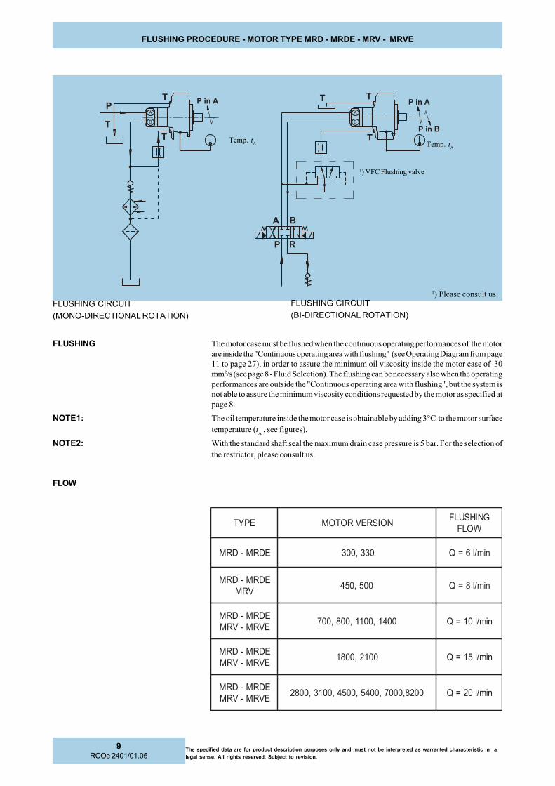
1) Please consult us.
EPYT NOISREVROTOMGNIHSULF
WOLF
EDRM-DRM 033,003 nim/l6=Q
EDRM-DRMVRM
005,054 nim/l8=Q
EDRM-DRMEVRM-VRM
0041,0011,008,007 nim/l01=Q
EDRM-DRMEVRM-VRM
0012,0081 nim/l51=Q
EDRM-DRMEVRM-VRM
0028,0007,0045,0054,0013,0082 nim/l02=Q
1) VFC Flushing valve
Temp. tA
Temp. tA
FLUSHING CIRCUIT
(MONO-DIRECTIONAL ROTATION)
FLUSHING CIRCUIT
(BI-DIRECTIONAL ROTATION)
FLUSHING The motor case must be flushed when the continuous operating performances of the motor
are inside the "Continuous operating area with flushing" (see Operating Diagram from page
11 to page 27), in order to assure the minimum oil viscosity inside the motor case of 30
mm2/s (see page 8 - Fluid Selection). The flushing can be necessary also when the operating
performances are outside the "Continuous operating area with flushing", but the system is
not able to assure the minimum viscosity conditions requested by the motor as specified at
page 8.
NOTE1: The oil temperature inside the motor case is obtainable by adding 3°C to the motor surface
temperature (tA , see figures).
NOTE2: With the standard shaft seal the maximum drain case pressure is 5 bar. For the selection of
the restrictor, please consult us.
FLOW
The specified data are for product description purposes only and must not be interpreted as warranted characteristic in a
legal sense. All rights reserved. Subject to revision.
10RCOe 2401/01.05
PILOTING PROCEDURE - MOTOR TYPE MRD - MRDE - MRV - MRVE
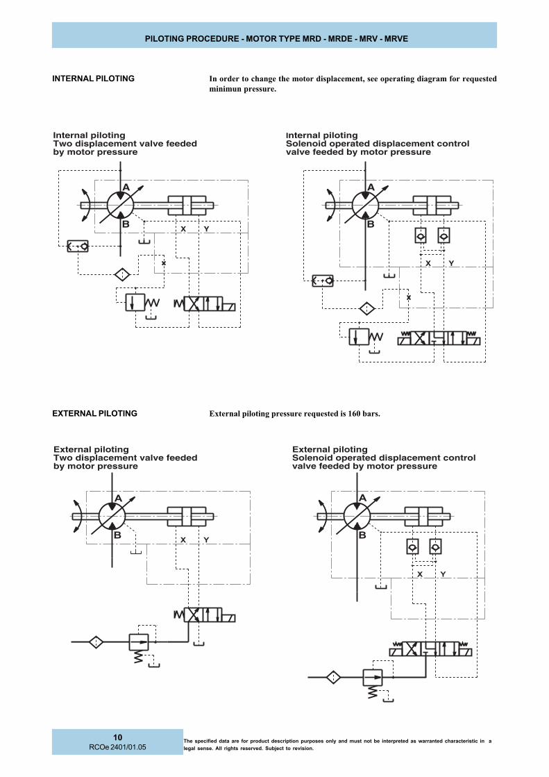
INTERNAL PILOTING In order to change the motor displacement, see operating diagram for requested
minimun pressure.
EXTERNAL PILOTING External piloting pressure requested is 160 bars.
Internal pilotingTwo displacement valve feededby motor pressure
Internal pilotingSolenoid operated displacement controlvalve feeded by motor pressure
X Y
A
B X Y B
A
External pilotingTwo displacement valve feededby motor pressure
External pilotingSolenoid operated displacement controlvalve feeded by motor pressure
�
� � �
� �

11RCOe 2401/01.05
The specified data are for product description purposes only and must not be interpreted as warranted characteristic in a
legal sense. All rights reserved. Subject to revision.
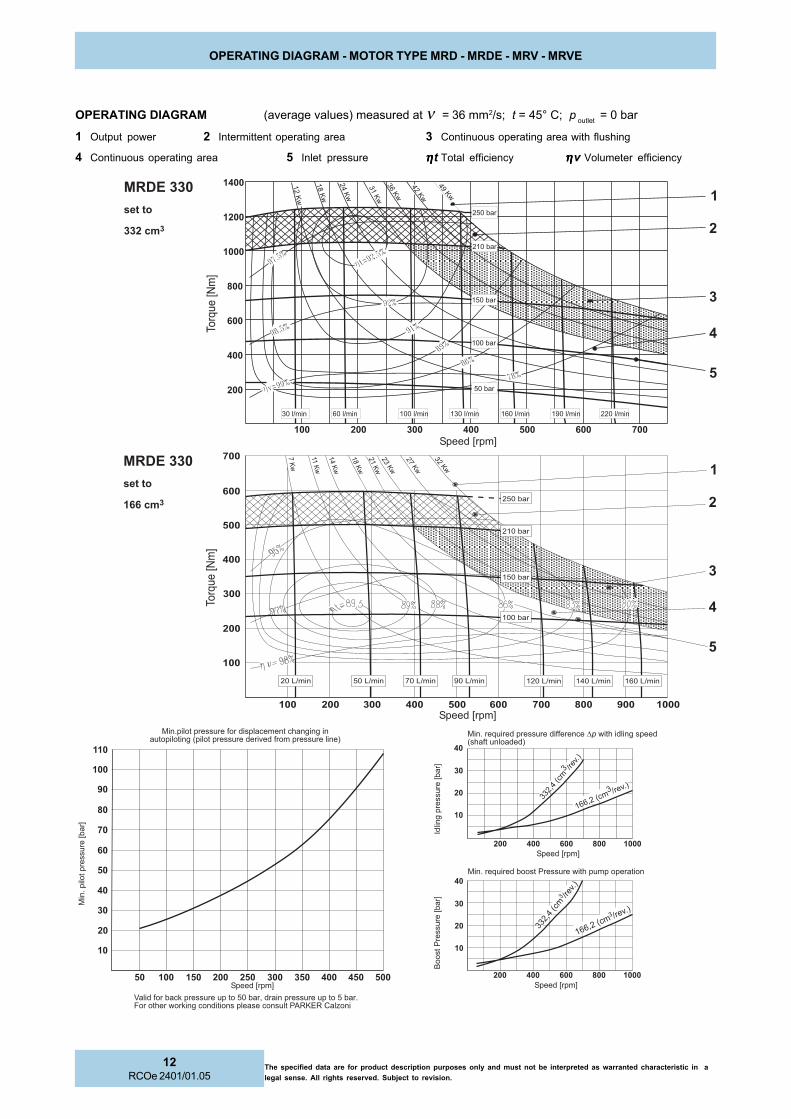
OPERATING DIAGRAM - MOTOR TYPE MRD - MRDE - MRV - MRVE
1 Output power 2 Intermittent operating area 3 Continuous operating area with flushing
4 Continuous operating area 5 Inlet pressure ηηηηηt Total efficiency ηηηηηv Volumeter efficiency
OPERATING DIAGRAM (average values) measured at ν = 36 mm2/s; t = 45° C; p outlet
= 0 bar
� � � � � � � � � �
�� ���� �������������� ���������������������� ������� ���� �������������������� ������������
������������ � ��������� ����!"����#������ ��������� ����!�����$���������%�� ������������ ��������������&�'()'�*��+��
���
����
��������,���-
�����.�����������&��������%��� �� �� ������
�����.����� ���������������������%��������� �������������������
/����� ���
�����,�
��-
���
���&��������,���-
���� ������
� �����
!�(%
0"�(%
0!�(%
1"�(%
1!�(%
2"�(%
2!�(%
30�(%
34�(%
!2�(%
3"��5�� 6"��5�� 7"��5��1"��5�� 0""��5�� 01"��5�� 03"��5�� 06"��5�� 07"��5�� 1""��5�� 11"��5��
�
�
�
�
�8�
�.��
�,9�-
: ����,� �-
2""����
1!"����
1""����
0!"����
0""����
!"����
� � � � � � � ��
��
��
�
�
�
�
�
���� ������
�������
�
�
�
�
�
8��.��
�,9�-
: ����,� �-
: ����,� �-� � � � �
�
: ����,� �-
: ����,� �-
�
�
�
� � � � �
2"3#0����
2 5�����
0!1#0���
�2 5���
��
�
�
� 0!1
#0����2 5���
��
2"3#0����
2 5�����
0""�;5��0!�;5�� 2!�;5�� 6"�;5�� 7"�;5�� 03!�;5��01"�;5��
6�(%
0"�(%
02�(%
06�(%
1"�(%
13�(%14�(%
20�(%
2""����
1!"����
1""����
0!"����
0""����
�
�
�
�
�
�
�
2!�(%
�
�
�
�
�
�
�
�
�
�
� � �� � �� � �� � �� �
The specified data are for product description purposes only and must not be interpreted as warranted characteristic in a
legal sense. All rights reserved. Subject to revision.
12RCOe 2401/01.05
OPERATING DIAGRAM - MOTOR TYPE MRD - MRDE - MRV - MRVE
1 Output power 2 Intermittent operating area 3 Continuous operating area with flushing
4 Continuous operating area 5 Inlet pressure ηηηηηt Total efficiency ηηηηηv Volumeter efficiency
OPERATING DIAGRAM (average values) measured at ν = 36 mm2/s; t = 45° C; p outlet
= 0 bar
�� ���� �������������� ���������������������� ������� ���� �������������������� ������������
�����.�����������&��������%��� �� �� ������
�����.����� ���������������������%��������� �������������������
������������ � ��������� ����!"����#������ ��������� ����!�����$���������%�� ������������ ��������������&�'()'�*��+��
/���
�� ���
�����,�
��-
���
���&����
����,���-
���
����
����
����,���-
: ����,� �- : ����,� �-
8��.��
�,9�-
: ����,� �-
������ ������
�������
: ����,� �-� � � �
�
�
�
�
�
221#3����2 5�����
066#1���
�2 5���
��
� � � � �
�
�
�
�
221#3����
2 5�����
066#1���
�2 5���
��
8��.��
�,9�-
: ����,� �-
������ ������
�������01�(
%
07�(%
13�(%
20�(%
3<�(%
26�(%
31�(%���
�����
���
�
���
���
���
�����
���
���
2"��5�� 6"��5�� 0""��5�� 02"��5�� 11"��5��0<"��5��06"��5��
�
� � � � � � �
��
�
�
�
�
��
!"����
0!"����
0""����
10"����
1!"����
�
�
�
�
�
�
�
�
�
�
01"�;5��
03�(%
07�(%
�
�
�
�
1"�;5��
� � � � � � �
!"�;5��
1!"����
0!"����
0""����
12�(%
14�(%
21�(%
�
�
�
� � �
10"����
00�(%
4�(%
4"�;5�� <"�;5�� 03"�;5�� 06"�;5��
10�(%
�
�
�
�
�
�
�
�
�
�
��
� � �� � �� � �� � �� �

13RCOe 2401/01.05
The specified data are for product description purposes only and must not be interpreted as warranted characteristic in a
legal sense. All rights reserved. Subject to revision.
OPERATING DIAGRAM - MOTOR TYPE MRD - MRDE - MRV - MRVE
1 Output power 2 Intermittent operating area 3 Continuous operating area with flushing
4 Continuous operating area 5 Inlet pressure ηηηηηt Total efficiency ηηηηηv Volumeter efficiency
OPERATING DIAGRAM (average values) measured at ν = 36 mm2/s; t = 45° C; p outlet
= 0 bar
�� ���� �������������� ���������������������� ������� ���� �������������������� ������������
�����.�����������&��������%��� �� �� ������
�����.����� ���������������������%��������� �������������������
������������ � ��������� ����!"����#������ ��������� ����!�����$���������%�� ������������ ��������������&�'()'�*��+��
/���
�� ���
�����,�
��-
���
���&����
����,���-
���
����
����
����,���-
: ����,� �- : ����,� �-
: ����,� �-� � � �
�
� � � �
3!0#!����2 5�����
11!#7��
��2 5���
����
�
�
��
� � � �
��
�
�
��
�
� � � �
�
3!0#!����2 5�����
11!#7���
�2 5���
��
�
�
�
�
�
8��.��
�,9�-
: ����,� �-
����� ������
�������02�(%
1"�(%
16�(%
22�(%
2<�(%
36�(%
!6�(%
6!�(%
4!�(%
6"��5�� <"��5��0"��5�� 2"��5�� 0!"��5�� 13"��5��10"��5��07"��5��01"��5��
�
�
�
�
�8�
�.��
�,9�-
: ����,� �-
2""����
1!"����
1""����
0!"����
0""����
!"����
��
�
��
��
��
��
�
�
�
�
�
� � � � � �
����� ������
�������
2""����
06�(%
01�(%
1"�(%
16�(%
1"�;5��
�
�
�
�
�
�
!"�;5�� 7"�;5��
22�(%
2<�(%
33�(%
0""����
0!"����
1""����
1!"����
7�(%
�
�
�
�
��
� � � � � � � � ��
07"�;5��00"�;5�� 02"�;5�� 06"�;5��
1<�(%
��
��
��
��
�
��
��
��
� � �� � �� � �� � �� �
��
�

The specified data are for product description purposes only and must not be interpreted as warranted characteristic in a
legal sense. All rights reserved. Subject to revision.
14RCOe 2401/01.05
OPERATING DIAGRAM - MOTOR TYPE MRD - MRDE - MRV - MRVE
1 Output power 2 Intermittent operating area 3 Continuous operating area with flushing
4 Continuous operating area 5 Inlet pressure ηηηηηt Total efficiency ηηηηηv Volumeter efficiency
OPERATING DIAGRAM (average values) measured at ν = 36 mm2/s; t = 45° C; p outlet
= 0 bar
�� ���� �������������� ���������������������� ������� ���� �������������������� ������������
�����.�����������&��������%��� �� �� ������
�����.����� ���������������������%��������� �������������������
������������ � ��������� ����!"����#������ ��������� ����!�����$���������%�� ������������ ��������������&�'()'�*��+��
/����� ���
�����,�
��-
���
���&��������,���-
���
����
��������,���-
: ����,� �- : ����,� �-
: ����,� �-
02�(%
1"�(%
16�(%
22�(%
2<�(%
36�(%
!6�(%
6!�(%
4!�(%
6"��5�� <"��5��0"��5�� 2"��5�� 0!"��5�� 13"��5��10"��5��07"��5��01"��5��
�
�
�
�
�8�
�.��
�,9�-
: ����,� �-
2""����
1!"����
1""����
0!"����
0""����
!"����
��
�
��
��
��
��
�
�
�
�
�
� � � � � �
����� ������
�������
����� ������
�������
8��.��
�,9�-
: ����,� �-
�
��
�
�
��
� � � �
3!0#!����2 5�����
022#!����
2 5�����
�
��
�
�
��
�
�
� � � �
3!0#!����2 5�����
022#!����
25�����
�
3�(%
<�(%
00�(%
11�(%
0<�(%
14�(%
21�(%
2!�(%
����
��
�����
�
���
������
���
� ����
��
���
47��5��<��5�� 3"��5�� !7��5�� 00!��5��<!��5��1"��5���
� � � � �
�
�
�
�
�
� � � � �
1!"����
0""����
0!"����
1""����
2""����
�
�
�
�
�
��
��
��
��
�
��
��
��
� � �� � �� � �� � �� �
��
�

15RCOe 2401/01.05
The specified data are for product description purposes only and must not be interpreted as warranted characteristic in a
legal sense. All rights reserved. Subject to revision.
OPERATING DIAGRAM - MOTOR TYPE MRD - MRDE - MRV - MRVE
1 Output power 2 Intermittent operating area 3 Continuous operating area with flushing
4 Continuous operating area 5 Inlet pressure ηηηηηt Total efficiency ηηηηηv Volumeter efficiency
OPERATING DIAGRAM (average values) measured at ν = 36 mm2/s; t = 45° C; p outlet
= 0 bar
�� ���� �������������� ���������������������� ������� ���� �������������������� ������������
�����.�����������&��������%��� �� �� ������
�����.����� ���������������������%��������� �������������������
������������ � ��������� ����!"����#������ ��������� ����!�����$���������%�� ������������ ��������������&�'()'�*��+��
/����� ���
�����,�
��-
���
���&��������,���-
���
����
��������,���-
�
�
�
�
�
�
�
�
�
�
7�(%
01�(%
06�(%
06�(%
11�(%
16�(%
20�(%
27�(%
: ����,� �- : ����,� �-
: ����,� �-
3<4#<����
2 5�����
����� ������
�������
8��.��
�,9�-
1!"����
07"��5�� 10"��5�� 13"��5�� 14"��5��6"��5�� 0!"��5��01"��5��
4�(%
02�(%
1"�(%
16�(%
22�(%
2<�(%
36�(%
!3�(%
61�(%
4"�(%
10"����
0!"����
0""����
!"����
2"��5��0"��5�� <"��5��
� � � � � �
�
��
��
��
��
�
�
�
�
�
: ����,� �-
����� ������
�������
8��.��
�,9�-
: ����,� �-
� � � �
��
�
�
��
�
��
�
137#<����
25�����
��
� � � �
��
�
�
�
��
�
137#<����
25�����3<4#<����
2 5�����
�
01!�;5��0""�;5�� 0!!�;5��1!�;5�� !"�;5�� 4!�;5��
�
�
� � � � � �
07"�;5��
0!"����
0""����
�
�
�
�
�
�
�
� �
10"����
1!"����
��
��
��
�
��
��
��
� � �� � �� � �� � �� �
��
�
��

The specified data are for product description purposes only and must not be interpreted as warranted characteristic in a
legal sense. All rights reserved. Subject to revision.
16RCOe 2401/01.05
OPERATING DIAGRAM - MOTOR TYPE MRD - MRDE - MRV - MRVE
1 Output power 2 Intermittent operating area 3 Continuous operating area with flushing
4 Continuous operating area 5 Inlet pressure ηηηηηt Total efficiency ηηηηηv Volumeter efficiency
OPERATING DIAGRAM (average values) measured at ν = 36 mm2/s; t = 45° C; p outlet
= 0 bar
�� ���� �������������� ���������������������� ������� ���� �������������������� ������������
�����.�����������&��������%��� �� �� ������
�����.����� ���������������������%��������� �������������������
������������ � ��������� ����!"����#������ ��������� ����!�����$���������%�� ������������ ��������������&�'()'�*��+��
/����� ���
�����,�
��-
���
���&��������,���-
���
����
��������,���-
06�(%
16�(%
10�(%
3"�(%
20�(%
26�(%
3!�(%
�
�
�
�
�
� � � � � � ��
0"�(%�
: ����,� �- : ����,� �-
: ����,� �-
���� ���� ������
� �����
<�(%
07�(%
17�(%
24�(%
36�(%
!6�(%
6!�(%
46�(%
76�(%
<4�(%
8��.��
�,9�-
: ����,� �-
2""����
1!"����
0!"����
0""����
!"����
1""����
� � �� � �� � �� � �� �
�
��
��
��
��
��
��
�
�
�
��
�
�
�
�
�
13"��5��01"��5�� 06"��5�� 1""��5�� 17"��5�� 21"��5��0!��5�� 3"��5�� 7"��5��
: ����,� �-
���� ���� ������
�������
8��.��
�,9�-
� � �
��
�
�
��
�
� � � �
�
��
4"6#<
����2 5��
���
124#6���
�2 5���
��
� � �
���
�
��
�
� � � �
� ���
4"6#<
����2 5��
���
124#6���
�2 5���
��
�
�
�
�
�2""����
04"��5��0!"��5��02"��5��0""��5��7"��5��!"��5��1"��5��
1!"����
1""����
0!"����
0!"����
��
�
��
�
��
�
��
� � �� � �� � �� �
�
��

17RCOe 2401/01.05
The specified data are for product description purposes only and must not be interpreted as warranted characteristic in a
legal sense. All rights reserved. Subject to revision.
OPERATING DIAGRAM - MOTOR TYPE MRD - MRDE - MRV - MRVE
1 Output power 2 Intermittent operating area 3 Continuous operating area with flushing
4 Continuous operating area 5 Inlet pressure ηηηηηt Total efficiency ηηηηηv Volumeter efficiency
OPERATING DIAGRAM (average values) measured at ν = 36 mm2/s; t = 45° C; p outlet
= 0 bar
�� ���� �������������� ���������������������� ������� ���� �������������������� ������������
�����.�����������&��������%��� �� �� ������
�����.����� ���������������������%��������� �������������������
������������ � ��������� ����!"����#������ ��������� ����!�����$���������%�� ������������ ��������������&�'()'�*��+��
/����� ���
�����,�
��-
���
���&��������,���-
���
����
��������,���-
�
�
�
�
�
� � � � � � � ��
�
�
�
�
� �
�
�
�
�
0<"��5��2"��5�� !"��5�� 7"��5�� 00"��5�� 02"��5�� 06"��5��
0!"����
0""����
10"����
1!"����0"�(
%
06�(%
10�(%
16�(%2"�(%
22�(%24�(%3"�(%
: ����,� �- : ����,� �-
: ����,� �-� � �
�
�
� � � ��
�
�
����� ����� ������
� �����
8��.��
�,9�-
00�(%
32�(%
!3�(%
6!�(%
43�(%
73�(%<2�(%
6"��5��1"��5�� 0""��5�� 1""��5��03"��5�� 07"��5�� 23"��5��2""��5��16"��5��
� � �� � �� � �� � ��
�
�
�
��
��
��
��
��
��
�
��
1!"����
10"����
0!"����
0""����
!"����
: ����,� �-
11�(%
22�(%
����� ����� ������
�� ����
8��.��
�,9�-
: ����,� �-
14"#1����
2 5�����
7"3#1����2 5��
���
� � �
�
�
� � � ��
�
�
7"3#1����
2 5�����
14"#1���
�2 5���
��
� � �� � �� � �� �
�
�
�
�
�
�

The specified data are for product description purposes only and must not be interpreted as warranted characteristic in a
legal sense. All rights reserved. Subject to revision.
18RCOe 2401/01.05
OPERATING DIAGRAM - MOTOR TYPE MRD - MRDE - MRV - MRVE
1 Output power 2 Intermittent operating area 3 Continuous operating area with flushing
4 Continuous operating area 5 Inlet pressure ηηηηηt Total efficiency ηηηηηv Volumeter efficiency
OPERATING DIAGRAM (average values) measured at ν = 36 mm2/s; t = 45° C; p outlet
= 0 bar
�� ���� �������������� ���������������������� ������� ���� �������������������� ������������
�����.�����������&��������%��� �� �� ������
�����.����� ���������������������%��������� �������������������
������������ � ��������� ����!"����#������ ��������� ����!�����$���������%�� ������������ ��������������&�'()'�*��+��
/����� ���
�����,�
��-
���
���&��������,���-
���
����
��������,���-
03�(%
1"�(%
14�(%
23�(%
2<�(%
33�(%
3<�(%
!3�(%
: ����,� �- : ����,� �-
: ����,� �-
�
�
�
�
�
11�(%
22�(%
33�(%
!!�(%
66�(%
44�(%
<0�(%
0"!�(%
00<�(%
2""����
0!"����
0""����
!"����
8��.��
�,9�-
: ����,� �-
�
�
��
�
��
�
��
�
��
�
��
� � �� � �� � ��
����� ����� ������
��������
1""����
1!"����
2""��5��0""��5�� 0!"��5�� 1""��5�� 1!"��5�� 2!"��5��!"��5��0!��5��
��
�
�
� � � �
��
�
� �
�
��
�
�
� � � �
��
�
� �
: ����,� �-
����� ����� ������
�������
270#2��
��2 5��
���
�
�
�
�
�
8��.��
�,9�-
001!#7����
2 5�����
270#2��
��2 5��
���
001!#7����
2 5�����
1"��5�� !"��5�� 7"��5�� 00"��5�� 03"��5�� 04"��5�� 10"��5��
� � �� � �� � �� �
��
�
��
�
��
�
��
�
�
�
�
� � � � �
�
�
�
�
��
��
��
0""����
0!"����
1""����
1!"����
2""����

19RCOe 2401/01.05
The specified data are for product description purposes only and must not be interpreted as warranted characteristic in a
legal sense. All rights reserved. Subject to revision.
OPERATING DIAGRAM - MOTOR TYPE MRD - MRDE - MRV - MRVE
1 Output power 2 Intermittent operating area 3 Continuous operating area with flushing
4 Continuous operating area 5 Inlet pressure ηηηηηt Total efficiency ηηηηηv Volumeter efficiency
OPERATING DIAGRAM (average values) measured at ν = 36 mm2/s; t = 45° C; p outlet
= 0 bar
�� ���� �������������� ���������������������� ������� ���� �������������������� ������������
�����.�����������&��������%��� �� �� ������
�����.����� ���������������������%��������� �������������������
������������ � ��������� ����!"����#������ ��������� ����!�����$���������%�� ������������ ��������������&�'()'�*��+��
/����� ���
�����,�
��-
���
���&��������,���-
���
����
��������,���-
� � �� �� � �� ��
�
�
��
�
��
�
��
�
��
�
�� �
�
�
�
�
� � �� �� � � �� �� �� ��
�
� � � � � ��
�
�
�
�
��
��
��
�� �
�
�
�
�
0!�(%
12�(%
2"�(%
27�(%31�(%34�(%!0�(%
!!�(%
: ����,� �- : ����,� �-
: ����,� �-
��
�
�
� � � �
��
�
� ��
�
362#<����
2 5�������
�2 5�����
362#<��
��2 5���
��
���
2 5�����
��
�
�
� � � �
��
�
� ��
�
������ ������ ������
��� ����
8��.��
�,9�-
: ����,� �-
11(%
22�(%
33�(%
!!�(%
66�(%
44�(%7!�(%
<3�(%0"1�(%
!"��5��0!��5�� 0""��5�� 1""��5�� 2""��5��0!"��5�� 1!"��5�� 2!"��5��
10"����
0!"����
0""����
1!"����
!"����
������ ������ ������
�������
8��.��
�,9�-
: ����,� �-
026<#!
026<#!
3"��5�� 4"��5�� 0""��5�� 02"��5�� 04"��5�� 1""��5�� 13"��5��
1!"����
0!"����
0""����
10"����
�
�
�
�
�

The specified data are for product description purposes only and must not be interpreted as warranted characteristic in a
legal sense. All rights reserved. Subject to revision.
20RCOe 2401/01.05
OPERATING DIAGRAM - MOTOR TYPE MRD - MRDE - MRV - MRVE
1 Output power 2 Intermittent operating area 3 Continuous operating area with flushing
4 Continuous operating area 5 Inlet pressure ηηηηηt Total efficiency ηηηηηv Volumeter efficiency
OPERATING DIAGRAM (average values) measured at ν = 36 mm2/s; t = 45° C; p outlet
= 0 bar
�� ���� �������������� ���������������������� ������� ���� �������������������� ������������
�����.�����������&��������%��� �� �� ������
�����.����� ���������������������%��������� �������������������
������������ � ��������� ����!"����#������ ��������� ����!�����$���������%�� ������������ ��������������=)9/:>9�*��+��
/����� ���
�����,�
��-
���
���&��������,���-
���
����
��������,���-
� � � � ��
�
�
��
�
��
� �� �� ��
07�(%
17�(%
24�(%
36�(%!1�(%!7�(%62�(%6<�(%
: ����,� �- : ����,� �-
: ����,� �-
����� ����� ������
��� ����
1<�(%
33�(%
!<�(%
43�(%
77�(%
0"2�(%
010�(%
02<�(%
0!4�(%
13"��5�� 2""��5�� 31"��5��26"��5��
�� � �� � ��� �� ��� � ��� ��
�
�
�
�
�
�
�
�
�
8��.��
�,9�-
�
�
�
�
�
: ����,� �-
2""����
1!"����
1""����
0!"����
0""����
!"����
1"��5�� 6"��5�� 01"��5�� 07"��5��
��
�
�
� � � �
��
�
�
��
�
�
� � � �
��
�
6"2#1���
�2 5���
��
����� ����� ������
� �����
8��.��
�,9�-
: ����,� �-
���
2 5�����
6"2#1���
�2 5���
�����
2 5�����
�
�
�
�
�
07"<#6
07"<#6
3"��5�� 4"��5�� 00"��5�� 03"��5�� 07"��5�� 10"��5�� 1!"�;5��
0""����
0!"����
1""����
2""����
1!"����
� � � � �
��
��
� �� �� �� ��
�
��
��
��
��
�
��

21RCOe 2401/01.05
The specified data are for product description purposes only and must not be interpreted as warranted characteristic in a
legal sense. All rights reserved. Subject to revision.
OPERATING DIAGRAM - MOTOR TYPE MRD - MRDE - MRV - MRVE
1 Output power 2 Intermittent operating area 3 Continuous operating area with flushing
4 Continuous operating area 5 Inlet pressure ηηηηηt Total efficiency ηηηηηv Volumeter efficiency
OPERATING DIAGRAM (average values) measured at ν = 36 mm2/s; t = 45° C; p outlet
= 0 bar
�� ���� �������������� ���������������������� ������� ���� �������������������� ������������
�����.�����������&��������%��� �� �� ������
�����.����� ���������������������%��������� �������������������
������������ � ��������� ����!"����#������ ��������� ����!�����$���������%�� ������������ ��������������&�'()'�*��+��
/���
�� ���
�����,�
��-
���
���&����
����,���-
���
����
����
����,���-
�
�
�
�
�
�
� � �� � �� � �� � ��
�
�
��
��
�
�
�
�
�
07�(%
17�(%
24�(%
36�(%
!2�(%
!<�(%
66�(%
41�(%
: ����,� �- : ����,� �-
: ����,� �-
������ ������ ������
� ������
8��.��
�,9�-
: ����,� �-
021�(%
037�(%
1"�(%
3"�(%
7"�(%
6"�(%
0""�(%
006�(%
1"��5�� 6"��5�� 01"��5�� 13"��5��07"��5�� 2""��5�� 37"��5��31"��5��26"��5��
0""����
1!"����
!"����
0!"����
10"����
�� � �� � ��� �� ��� � ��� ��
�
�
�
�
�
�
�
�
��
��
�
�
� � � �
��
�
�
6<4#"����
25�����
���
2 5�����
1"<0#1
��
��
�
�
� � � �
��
�
�
6<4#"����
2 5�������
�2 5�����
1"<0#1
������ ������ ������
�������
8��.��
�,9�-
: ����,� �-
!"��5�� 4"��5�� 00"��5�� 0!"��5�� 07"��5�� 11"��5�� 14"��5��
1!"����
0!"����
0""����
10"����
� � � � � �� �� �� ��
�
��
�
��
�
�

The specified data are for product description purposes only and must not be interpreted as warranted characteristic in a
legal sense. All rights reserved. Subject to revision.
22RCOe 2401/01.05
OPERATING DIAGRAM - MOTOR TYPE MRD - MRDE - MRV - MRVE
1 Output power 2 Intermittent operating area 3 Continuous operating area with flushing
4 Continuous operating area 5 Inlet pressure ηηηηηt Total efficiency ηηηηηv Volumeter efficiency
OPERATING DIAGRAM (average values) measured at ν = 36 mm2/s; t = 45° C; p outlet
= 0 bar
�� ���� �������������� ���������������������� ������� ���� �������������������� ������������
�����.�����������&��������%��� �� �� ������
�����.����� ���������������������%��������� �������������������
������������ � ��������� ����!"����#������ ��������� ����!�����$���������%�� ������������ ��������������&�'()'�*��+��
/����� ���
�����,�
��-
���
���&��������,���-
���
����
��������,���-
�
�
�
�
�
�
�
�
�
�
��
��
��
� � � � � �� �� �� �� � ���
�� �
�
��
�
�
�
�
��
� � �� ��
�
��
: ����,� �- : ����,� �-
: ����,� �-
��
��
�
� � �� ��
�
�
� �� ��
<2"#4����
2 5�����
���2 5�����
14<1
��
��
�
� � �� ��
�
�
� �� ��
<2"#4����
25��������
2 5�����
14<1
����� ����� ������
��������
1"�(%
3"�(%
6"�(%
7"�(%
0""�(%
014�(%
03<�(%
041�(%
0<3�(%
8��.��
�,9�-
: ����,� �-
2""����
1!"����
1""����
0!"����
0""����
!"����
�
�
�
�
�
1!��5�� 7"��5�� 06"��5�� 13"��5�� 21"��5�� 3""��5�� 37"��5�� !2"��5��
: ����,� �-
����� ����� ������
�������
8��.��
�,9�-
0!"����
10�(%
20�(%
31�(%
!1�(%!<�(%66�(%42�(%
7"�(%
�
�
�
�
�
2"��5�� 7"��5�� 01"��5�� 06"��5�� 1""��5�� 13"��5�� 14"��5��
1!"����
0""����
1""����
2""����
�� �� �� �� � � � � �� ���
�
��
�
��
�
�

23RCOe 2401/01.05
The specified data are for product description purposes only and must not be interpreted as warranted characteristic in a
legal sense. All rights reserved. Subject to revision.
OPERATING DIAGRAM - MOTOR TYPE MRD - MRDE - MRV - MRVE
1 Output power 2 Intermittent operating area 3 Continuous operating area with flushing
4 Continuous operating area 5 Inlet pressure ηηηηηt Total efficiency ηηηηηv Volumeter efficiency
OPERATING DIAGRAM (average values) measured at ν = 36 mm2/s; t = 45° C; p outlet
= 0 bar
�� ���� �������������� ���������������������� ������� ���� �������������������� ������������
�����.�����������&��������%��� �� �� ������
�����.����� ���������������������%��������� �������������������
������������ � ��������� ����!"����#������ ��������� ����!�����$���������%�� ������������ ��������������&�'()'�*��+��
/���
�� ���
�����,�
��-
���
���&����
����,���-
���
����
����
����,���-
� � � � � �� �� �� �� � ���
11�(%
22�(%
33�(%
!!�(%
62�(%4"�(%
47�(%7!�(%
�
��
��
�
�
�
�
�
�� � �� �
��
�
: ����,� �- : ����,� �-
: ����,� �-
��
�
�
� � �� ��
�
� �� ��
��
0"23#7����
25�����20"2#4����
2 5�����
��
�
�
� � �� ��
�
� �� ��
��
0"23#7����
25�����
20"2#4����
2 5�����
8��.��
�,9�-
������ ������ ������
� ������
: ����,� �-
: ����,� �-
8��.��
�,9�-
������ ������ ������
�� �����
13"��5��
�
�
�
�
�
1"�(%
3"�(%
6"�(%
7"�(%
0""�(%
01!�(%
03!�(%
06!�(%
0<"�(%
0""����
1!"����
!"����
0!"����
10"����
3""��5��06"��5�� 21"��5�� !!"��5��37"��5��1!��5�� 7"��5���
�
�
�
�
�
�
�
�
�
��
��
��
�
�
�
�
�
!"��5�� 7"��5�� 01"��5�� 0!"��5�� 0<"��5�� 12"��5�� 17"��5��
1!"����
0!"����
0""����
10"����
�� �� �� �� � � � � �� ���
�
�
��
�
��
�
��

The specified data are for product description purposes only and must not be interpreted as warranted characteristic in a
legal sense. All rights reserved. Subject to revision.
24RCOe 2401/01.05
OPERATING DIAGRAM - MOTOR TYPE MRD - MRDE - MRV - MRVE
1 Output power 2 Intermittent operating area 3 Continuous operating area with flushing
4 Continuous operating area 5 Inlet pressure ηηηηηt Total efficiency ηηηηηv Volumeter efficiency
OPERATING DIAGRAM (average values) measured at ν = 36 mm2/s; t = 45° C; p outlet
= 0 bar
�� ���� �������������� ���������������������� ������� ���� �������������������� ������������
�����.�����������&��������%��� �� �� ������
�����.����� ���������������������%��������� �������������������
������������ � ��������� ����!"����#������ ��������� ����!�����$���������%�� ������������ ��������������&�'()'�*��+��
/����� ���
�����,�
��-
���
���&��������,���-
���
����
��������,���-
�
�
�
�
�
��
��
��
��
�
��
� � � � � �� �� �� ��
�
�
�
�
�
�
�
�
� � �� �� ��
�
�
�
�
�
�
�
�
�
�
���� ��� ������
: ����,� �- : ����,� �-
: ����,� �-
8��.��
�,9�-
: ����,� �-
����� ����� ������
��������
��
�
�
� � �� �
�
��
��
��
�
�
� � �� �
�
��
��
�
3"�(%
6"�(%
7"�(%
03"�(%
062�(%
074�(%
10"�(%
0""�(%
01"�(%
8��.��
�,9�-
: ����,� �-
2""����
1!"����
1""����
0!"����
0""����
!"����
����� ����� ������
�� �����
2""��5��1""��5�� 3""��5�� !""��5�� 6""��5�� 4""��5��2!��5�� 0""��5��
3!"1#4�
���
2 5�����
03<4#7����
25�����
03<4#7����
25�����
3!"1#4
����
2 5�����
11�(%
33�(%
!!�(%62�(%4"�(%47�(%7!�(%
22�(%
4"��5�� 0""��5�� 0!"��5�� 0<"��5�� 13"��5�� 1<"��5�� 26"��5��
0!"����
0""����
1""����
2""����
1!"����
� �� � � �
��
��
��
��
��
�
��
��
��

25RCOe 2401/01.05
The specified data are for product description purposes only and must not be interpreted as warranted characteristic in a
legal sense. All rights reserved. Subject to revision.
OPERATING DIAGRAM - MOTOR TYPE MRD - MRDE - MRV - MRVE
1 Output power 2 Intermittent operating area 3 Continuous operating area with flushing
4 Continuous operating area 5 Inlet pressure ηηηηηt Total efficiency ηηηηηv Volumeter efficiency
OPERATING DIAGRAM (average values) measured at ν = 36 mm2/s; t = 45° C; p outlet
= 0 bar
�� ���� �������������� ���������������������� ������� ���� �������������������� ������������
�����.�����������&��������%��� �� �� ������
�����.����� ���������������������%��������� �������������������
������������ � ��������� ����!"����#������ ��������� ����!�����$���������%�� ������������ ��������������&�'()'�*��+��
/����� ���
�����,�
��-
���
���&��������,���-
���
����
��������,���-
�
�
�
�
�
� � � �� ��
�
�
�
�
�
16�(%
2<�(%
!1�(%
6!�(%
43�(%
72�(%<0�(%
0""�(%
�
�
�
�
�
�
�
: ����,� �- : ����,� �-
: ����,� �-
������ ������ ������
�� �����
8��.��
�,9�-
: ����,� �-
2!��5�� 0""��5�� 1""��5�� 3""��5��2""��5�� 7""��5��4""��5��6""��5��!""��5��
3"�(%
6"�(%
7"�(%
03"�(%
062�(%
074�(%
0""�(%
10"�(%
0""����
1!"����
!"����
0!"����
10"����
� � � � � �� �� ��
�
�
�
�
�
��
��
��
��
�
��
01"�(%
��
�
�
� � �� ��
�
�
��
�
��
��
07""#3����
25�����!3"0#1����
2 5�����
��
�
�
� � �� ��
�
�
��
�
��
��
07""#3���
�2 5����
�
!3"0#1�
���
2 5�����
������ ������ ������
�� ����
8��.��
�,9�-
: ����,� �-
6"��5�� 00"��5�� 04"��5�� 11"��5�� 17"��5�� 22"��5�� 30"��5��
1!"����
0!"����
0""����
10"����
� �� � � �
��
��
��
��
�
�
��
�

The specified data are for product description purposes only and must not be interpreted as warranted characteristic in a
legal sense. All rights reserved. Subject to revision.
26RCOe 2401/01.05
OPERATING DIAGRAM - MOTOR TYPE MRD - MRDE - MRV - MRVE
1 Output power 2 Intermittent operating area 3 Continuous operating area with flushing
4 Continuous operating area 5 Inlet pressure ηηηηηt Total efficiency ηηηηηv Volumeter efficiency
OPERATING DIAGRAM (average values) measured at ν = 36 mm2/s; t = 45° C; p outlet
= 0 bar
�
�
�
�
�
&�������������������
&�������
����
��������
�
1211#3����
25�����
6<64#1�
���
2 5�����
1211#3����
25���������
2 5�����
6<64#1
�
�
�
�
�
�
�
� � �� �� �
�
�
�
�� ���� �������������� ���������������������� ������� ���� �������������������� ������������
�����.�����������&��������%��� �� �� ������
�����.����� ���������������������%��������� �������������������
������������ � ��������� ����!"����#������ ��������� ����!�����$���������%�� ������������ ��������������&�'()'�*��+��
���
����
��������,���-
���� ���� ������
��������
8��.��
�,9�-
3<�(%
42�(%
<4�(%
04"�(%
1""�(%
12"�(%
1!"�(%
2""����
1""����
0!"����
0""����
!"����
7""��5��2!��5�� 0""��5�� 1""��5�� 2""��5�� 3""��5�� !""��5�� 4""��5��6""��5��
� � � � � � � � � � �� �� ��
��
�
��
��
��
��
��
��
�
�
�
: ����,� �-010�(%
036�(%
1!"����
��
�
�
� �� �� ��
�
�
��
��
�
�
� �� �� ��
�
�
��
�
8��.��
�,9�-
: ����,� �-
���� ���� ������
��������
: ����,� �- : ����,� �-
: ����,� �-
22�(%
<1�(%0"0�(%000�(%01"�(%
3<�(%
66�(%
4"��5�� 02"��5�� 0<"��5�� 1!"��5�� 21"��5�� 27"��5�� 3!"��5��
0!"����
0""����
1""����
2""����
1!"����
71�(%
� �� �� � ��
��
��
�
��
��
��
��
��
��

27RCOe 2401/01.05
The specified data are for product description purposes only and must not be interpreted as warranted characteristic in a
legal sense. All rights reserved. Subject to revision.
OPERATING DIAGRAM - MOTOR TYPE MRD - MRDE - MRV - MRVE
1 Output power 2 Intermittent operating area 3 Continuous operating area with flushing
4 Continuous operating area 5 Inlet pressure ηηηηηt Total efficiency ηηηηηv Volumeter efficiency
OPERATING DIAGRAM (average values) measured at ν = 36 mm2/s; t = 45° C; p outlet
= 0 bar
������������ � ��������� ����!"����#������ ��������� ����!�����$���������%�� ������������ ��������������&�'()'�*��+��
�
�
�
�
�
���
�������
���
������
���
����
1431#0����
25���������
2 5�����
7116#3
�
�
�
�
�
21�(%
37�(%
63�(%
7"�(%
<3�(%
0"4�(%
010�(%
023�(%
�� � �� � ���
�
�
�
�
�� ��� �
�
�����.�����������&��������%��� �� �� ������
������ ������ ������
��������
8��.��
�,9�-
: ����,� �-
2!��5�� 0""��5�� 1""��5�� 3""��5��2""��5�� 7""��5��4""��5��6""��5��!""��5��
3"�(%
6"�(%
7"�(%
03"�(%
062�(%
074�(%
0""�(%
10"�(%
0""����
1!"����
!"����
0!"����
10"����
� � � � � �� �� ��
�
�
�
�
�
��
��
��
��
�
��
01"�(%
������ ������ ������
��������
8��.��
�,9�-
: ����,� �-
��
�
�
� � �� ��
�
�
��
��
�
�
� �� �� ��
�
�
��
�
1431#0����
25�����
7116#3
����
2 5�����
: ����,� �-
7"��5�� 03"��5�� 10"��5�� 14"��5�� 23"��5�� 30"��5�� 3<"��5��
1!"����
0!"����
0""����
10"����
� �� � � �
��
��
��
��
�
�
��
�
The specified data are for product description purposes only and must not be interpreted as warranted characteristic in a
legal sense. All rights reserved. Subject to revision.
28RCOe 2401/01.05
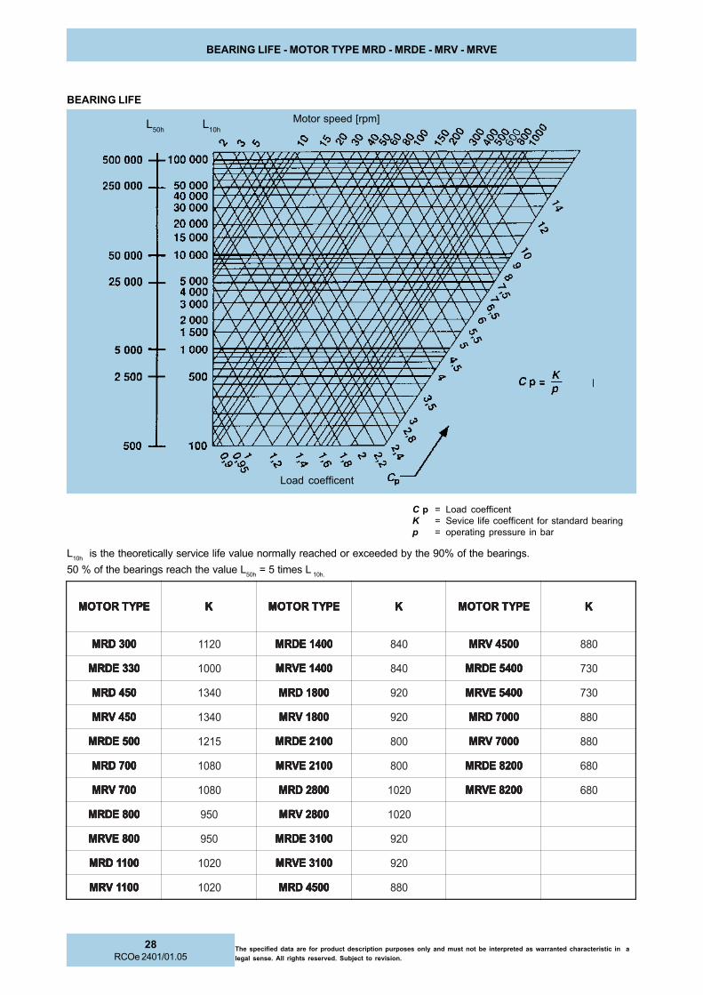
BEARING LIFE - MOTOR TYPE MRD - MRDE - MRV - MRVE
L10h
is the theoretically service life value normally reached or exceeded by the 90% of the bearings.
50 % of the bearings reach the value L50h
= 5 times L 10h.
C p = Load coefficentK = Sevice life coefficent for standard bearingp = operating pressure in bar
EPYTROTOM EPYTROTOM EPYTROTOM EPYTROTOM EPYTROTOM KKKKK EPYTROTOM EPYTROTOM EPYTROTOM EPYTROTOM EPYTROTOM KKKKK EPYTROTOM EPYTROTOM EPYTROTOM EPYTROTOM EPYTROTOM KKKKK
003DRM 003DRM 003DRM 003DRM 003DRM 0211 0041EDRM 0041EDRM 0041EDRM 0041EDRM 0041EDRM 048 0054VRM 0054VRM 0054VRM 0054VRM 0054VRM 088
033EDRM 033EDRM 033EDRM 033EDRM 033EDRM 0001 0041EVRM 0041EVRM 0041EVRM 0041EVRM 0041EVRM 048 0045EDRM 0045EDRM 0045EDRM 0045EDRM 0045EDRM 037
054DRM 054DRM 054DRM 054DRM 054DRM 0431 0081DRM 0081DRM 0081DRM 0081DRM 0081DRM 029 0045EVRM 0045EVRM 0045EVRM 0045EVRM 0045EVRM 037
054VRM 054VRM 054VRM 054VRM 054VRM 0431 0081VRM 0081VRM 0081VRM 0081VRM 0081VRM 029 0007DRM 0007DRM 0007DRM 0007DRM 0007DRM 088
005EDRM 005EDRM 005EDRM 005EDRM 005EDRM 5121 0012EDRM 0012EDRM 0012EDRM 0012EDRM 0012EDRM 008 0007VRM 0007VRM 0007VRM 0007VRM 0007VRM 088
007DRM 007DRM 007DRM 007DRM 007DRM 0801 0012EVRM 0012EVRM 0012EVRM 0012EVRM 0012EVRM 008 0028EDRM 0028EDRM 0028EDRM 0028EDRM 0028EDRM 086
007VRM 007VRM 007VRM 007VRM 007VRM 0801 0082DRM 0082DRM 0082DRM 0082DRM 0082DRM 0201 0028EVRM 0028EVRM 0028EVRM 0028EVRM 0028EVRM 086
008EDRM 008EDRM 008EDRM 008EDRM 008EDRM 059 0082VRM 0082VRM 0082VRM 0082VRM 0082VRM 0201
008EVRM 008EVRM 008EVRM 008EVRM 008EVRM 059 0013EDRM 0013EDRM 0013EDRM 0013EDRM 0013EDRM 029
0011DRM 0011DRM 0011DRM 0011DRM 0011DRM 0201 0013EVRM 0013EVRM 0013EVRM 0013EVRM 0013EVRM 029
0011VRM 0011VRM 0011VRM 0011VRM 0011VRM 0201 0054DRM 0054DRM 0054DRM 0054DRM 0054DRM 088
BEARING LIFE
Motor speed [rpm]
Load coefficent
L50h
L10h
29RCOe 2401/01.05
The specified data are for product description purposes only and must not be interpreted as warranted characteristic in a
legal sense. All rights reserved. Subject to revision.
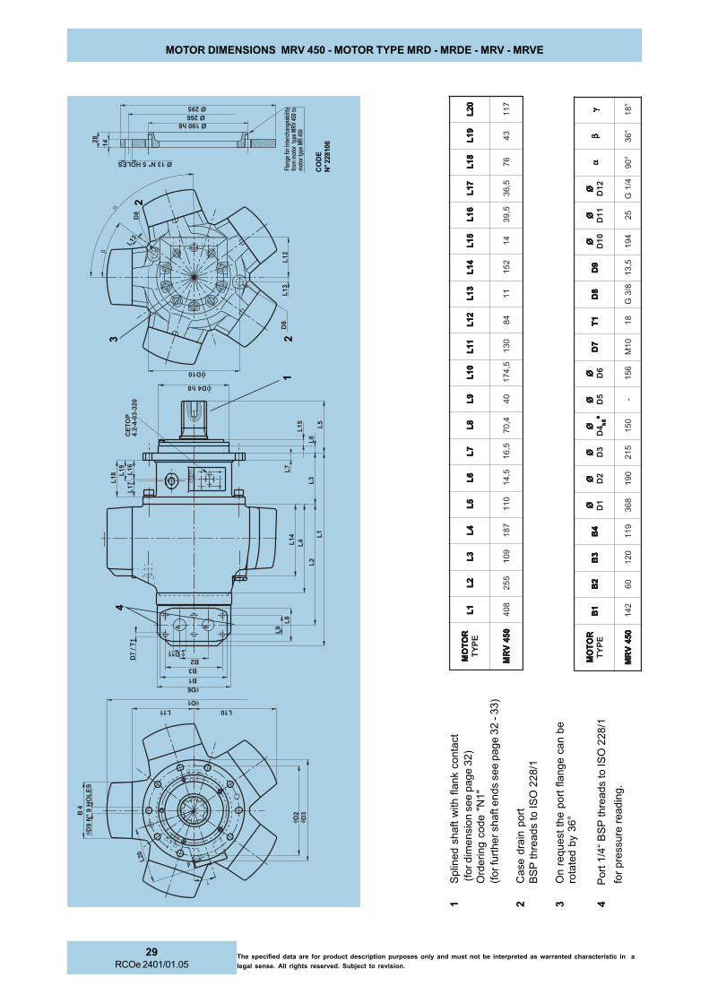
MOTOR DIMENSIONS MRV 450 - MOTOR TYPE MRD - MRDE - MRV - MRVE
RO
TO
MR
OT
OM
RO
TO
MR
OT
OM
RO
TO
ME
PY
T1
B1
B1
B1
B1
B2
B2
B2
B2
B2
B3
B3
B3
B3
B3
B4
B4
B4
B4
B4
BØØ ØØØ 1
DØØ ØØØ2
DØØ ØØØ3
DØØ ØØØ 4
D8
h8
h8
h8
h8
h** ***
ØØ ØØØ5
DØØ ØØØ6
D7
D7
D7
D7
D7
D1
T1
T1
T1
T1
T8
D8
D8
D8
D8
D9
D9
D9
D9
D9
DØØ ØØØ
01
DØØ ØØØ
11
DØØ ØØØ
21
Dαα ααα
ββ βββγγ γγγ
05
4V
RM
05
4V
RM
05
4V
RM
05
4V
RM
05
4V
RM
24
10
60
21
91
18
63
09
15
12
05
1-
65
10
1M
81
8/3
G5,
31
49
15
24/
1G
°0
9°
63
°8
1
RO
TO
MR
OT
OM
RO
TO
MR
OT
OM
RO
TO
ME
PY
T1
L1
L1
L1
L1
L2
L2
L2
L2
L2
L3
L3
L3
L3
L3
L4
L4
L4
L4
L4
L5
L5
L5
L5
L5
L6
L6
L6
L6
L6
L7
L7
L7
L7
L7
L8
L8
L8
L8
L8
L9
L9
L9
L9
L9
L0
1L
01
L0
1L
01
L0
1L
11
L1
1L
11
L1
1L
11
L2
1L
21
L2
1L
21
L2
1L
31
L3
1L
31
L3
1L
31
L4
1L
41
L4
1L
41
L4
1L
51
L5
1L
51
L5
1L
51
L6
1L
61
L6
1L
61
L6
1L
71
L7
1L
71
L7
1L
71
L8
1L
81
L8
1L
81
L8
1L
91
L9
1L
91
L9
1L
91
L0
2L
02
L0
2L
02
L0
2L
05
4V
RM
05
4V
RM
05
4V
RM
05
4V
RM
05
4V
RM
80
45
52
90
17
81
01
15,
41
5,6
14,
07
04
5,4
71
03
14
81
12
51
41
5,9
35,
63
67
34
71
1
1S
plin
ed s
haft w
ith f
lank
conta
ct (fo
r dim
ensi
on s
ee p
age 3
2)
Ord
ering c
ode "
N1"
(for fu
rther sh
aft e
nds
see p
age 3
2 - 3
3)
2C
ase
dra
in p
ort
BS
P thre
ads
to IS
O 2
28/1
3O
n r
equest
the p
ort
fla
nge c
an b
ero
tate
d b
y 36°
4
Port
1/4
“ B
SP
thre
ads
to IS
O 2
28/1
fo
r pre
ssure
readin
g.
4
23
1
2
����
��� �!�
��
����"#���$%&�'
��
����
��
&��
�
&��
&�
&�
&�
&�
&�
&�
&�
&�
�������
�����
��
&�� &�� &��
&��
���
��
&��
&��
&��
���(���
&��
&�
����!�
���� ��
� ����
� ���"#���$%&�'
&�
�
&� ��
��
)��%�
�*�+�+ �+��
,-.�/��0�1�����1�!.�/�.2�-��3
01�������1���34���
���� ���
����1��34������
CO
DE
N° 228106

The specified data are for product description purposes only and must not be interpreted as warranted characteristic in a
legal sense. All rights reserved. Subject to revision.
30RCOe 2401/01.05
MOTOR DIMENSIONS - MOTOR TYPE MRD - MRDE - MRV - MRVE
4
2
2
13
1S
plin
ed s
haft w
ith fl
ank
conta
ct (fo
r dim
ensi
on s
ee p
age 3
2)
Ord
ering c
ode "N
1"
(for f
urt
her s
haft e
nds
see p
age 3
2 -
33)
2C
ase
dra
in p
ort
BS
P th
reads
to IS
O 2
28/1
3O
n request
the p
ort
flange c
an b
e rota
ted b
y 72°
(For M
RD
300, M
RD
E 3
30, M
RD
450, M
RD
E 5
00, M
RD
700,
MR
V 7
00, M
RD
E 8
00 ,M
RV
E 8
00 c
an b
e r
ota
ted b
y 36°)
For
standard
posi
tion s
ee a
nge
aaaa a
4P
ort
1/4
“ B
SP
thre
ads
to IS
O 2
28/1
for
pre
ssure
readin
g.
5R
ota
ry v
alv
e h
ousi
ng w
ith B
SP
thre
ads
(fro
m M
RD
2800 to
MR
DE
8200) a
vaila
ble
on re
quest
, ple
ase
conta
ct P
ark
er C
alz
oni.
noitatoRfo.riD)dnetfahs
node
weiV(telnitroP
edocgniredro
)74egapees(
esiwkcolc
esiwkcolc-itna
A B"N"
esiwkcolc
esiwkcolc-itna
B A"S"
�?
�?
&�
&�
&�&�
&�
&�
���
���!�
&�
���������
&�
&�
��(��
����� �
����
���
��
��� ���
&��
&�� &�
&��
&����
���
��
��&��
&��&���
)��%���*�+�+ �+��
"�""""
� �
��(��+�'��
&��+�'��
���+�'�����+�'��
&�
�����+�'��
5

31RCOe 2401/01.05
The specified data are for product description purposes only and must not be interpreted as warranted characteristic in a
legal sense. All rights reserved. Subject to revision.
MOTOR DIMENSIONS - MOTOR TYPE MRD - MRDE - MRV - MRVE
RO
TO
MR
OT
OM
RO
TO
MR
OT
OM
RO
TO
ME
PY
T1
B1
B1
B1
B1
B2
B2
B2
B2
B2
B
EA
S-
2B
EA
S-
2B
EA
S-
2B
EA
S-
2B
EA
S-
2B
3B
3B
3B
3B
3B
EA
S-
3B
EA
S-
3B
EA
S-
3B
EA
S-
3B
EA
S-
3B
4B
4B
4B
4B
4B
ØØ ØØØ1
DØØ ØØØ2
DØØ ØØØ3
DØØ ØØØ 4
D8
h8
h8
h8
h8
h*
****
**
**
*ØØ ØØØ5
DØØ ØØØ6
D1
T-7
D1
T-7
D1
T-7
D1
T-7
D1
T-7
D
EA
S-
1T-
7D
EA
S-
1T-
7D
EA
S-
1T-
7D
EA
S-
1T-
7D
EA
S-
1T-
7D
8D
8D
8D
8D
8D
9D
9D
9D
9D
9D
ØØ ØØØ0
1D
ØØ ØØØ1
1D
EA
S-
11
DØ
EA
S-
11
DØ
EA
S-
11
DØ
EA
S-
11
DØ
EA
S-
11
DØ
ØØ ØØØ2
1D
OL
*O
L*
OL
*O
L*
OL
*W
ER
US
SE
RP
HGI
H*
HGI
H*
HGI
H*
HGI
H*
HGI
H*
ER
US
SE
RP
WO
L*
WO
L*
WO
L*
WO
L*
WO
L*
ER
US
SE
RP
HGI
H*
HGI
H*
HGI
H*
HGI
H*
HGI
H*
ER
US
SE
RP
WO
L*
WO
L*
WO
L*
WO
L*
WO
L*
ER
US
SE
RP
HGI
H*
HGI
H*
HGI
H*
HGI
H*
HGI
H*
ER
US
SE
RP
WO
L*
WO
L*
WO
L*
WO
L*
WO
L*
ER
US
SE
RP
HGI
H*
HGI
H*
HGI
H*
HGI
H*
HGI
H*
ER
US
SE
RP
00
3D
RM
00
3D
RM
00
3D
RM
00
3D
RM
00
3D
RM
03
3E
DR
M0
21
05
--0
01
--0
01
82
32
32
65
25
71
09
92
15
1-8
M--
8/3
G1
12
61
02
--4/
1G
05
4D
RM
05
4D
RM
05
4D
RM
05
4D
RM
05
4D
RM
00
5E
DR
M2
41
06
--0
21
--9
11
86
36
62
69
20
91
69
65
18
1-0
1M
--8/
3G
31
49
15
2--
4/1
G
00
7D
RM
00
7D
RM
00
7D
RM
00
7D
RM
00
7D
RM
00
8E
DR
M0
07
VR
M0
08
EV
RM
24
10
6--
02
1--
33
15
04
09
20
23
02
22
01
65
18
1-0
1M
--8/
3G
31
70
25
2--
4/1
G
00
11
DR
M0
01
1D
RM
00
11
DR
M0
01
1D
RM
00
11
DR
M0
04
1E
DR
M0
01
1V
RM
00
41
EV
RM
26
13
7--
--6
31
----
84
10
74
03
37
63
05
20
21
27
11
2-2
1M
----
2/1
G5
18
22
13
----
4/1
G
00
81
DR
M0
08
1D
RM
00
81
DR
M0
08
1D
RM
00
81
DR
M0
01
2E
DR
M0
08
1V
RM
00
12
EV
RM
26
13
7--
--6
31
----
86
18
55
08
33
24
09
28
41
27
11
2-2
1M
----
2/1
G7
16
62
13
----
4/1
G
00
82
DR
M0
08
2D
RM
00
82
DR
M0
08
2D
RM
00
82
DR
M0
01
3E
DR
M0
08
2V
RM
00
13
EV
RM
33
26
86
81
01
08
17,
53
5,6
30
91
24
60
44
49
45
33
04
15
12
82-
41
M0
3-2
1M
53-
61
M2/
1G
91
41
37
37
37
34/
1G
00
54
DR
M0
05
4D
RM
00
54
DR
M0
05
4D
RM
00
54
DR
M0
04
5E
DR
M0
05
4V
RM
00
45
EV
RM
33
26
11
61
16
11
00
28
8,2
45
4,4
40
42
66
70
45
79
50
04 4
D4
D4
D4
D4
D7
h7
h7
h7
h7
h*
****
**
**
*-
51
28
2-6
1M
03-
21
M4
3-0
2M
2/1
G3
20
83
83
05
05
4/1
G
00
07
DR
M0
00
7D
RM
00
07
DR
M0
00
7D
RM
00
07
DR
M0
02
8E
DR
M0
00
7V
RM
00
28
EV
RM
33
26
11
61
16
11
00
28
8,2
45
4,4
44
62
46
80
06
6,8
56
05
4 4D
4D
4D
4D
4D
7h
7h
7h
7h
7h
*****
**
**
*0
91
51
28
2-6
1M
03-
21
M4
3-0
2M
2/1
G5
20
54
83
05
05
4/1
G
in
ozl
aC
RE
KR
AP
TL
US
NO
CE
SA
EL
P,
DA
ER
HT
CN
UE
LB
ALI
VA
OS
LA
Ñ.
SE
UL
AV
"IS
PE
AS"
"S
EG
NA
LF
NOI
TC
EN
NO
CE
AS"
24.
GA
PO
TR
EF
ER
ES
AE
LP
SE
UL
AV
ER
US
SE
RP
RO
F*
RO
TO
MR
OT
OM
RO
TO
MR
OT
OM
RO
TO
ME
PY
T1
L1
L1
L1
L1
L2
L2
L2
L2
L2
L3
L3
L3
L3
L3
L4
L4
L4
L4
L4
L5
L5
L5
L5
L5
L6
L6
L6
L6
L6
L7
L7
L7
L7
L7
L8
L8
L8
L8
L8
L9
L9
L9
L9
L9
L
EA
S-
9L
EA
S-
9L
EA
S-
9L
EA
S-
9L
EA
S-
9L
01
L0
1L
01
L0
1L
01
L1
1L
11
L1
1L
11
L1
1L
21
L2
1L
21
L2
1L
21
L3
1L
31
L3
1L
31
L3
1L
41
L4
1L
41
L4
1L
41
L5
1L
51
L5
1L
51
L5
1L
61
L6
1L
61
L6
1L
61
Laa aaa
bb bbbgg ggg
WO
L*
WO
L*
WO
L*
WO
L*
WO
L*
ER
US
SE
RP
HGI
H*
HGI
H*
HGI
H*
HGI
H*
HGI
H*
ER
US
SE
RP
00
3D
RM
00
3D
RM
00
3D
RM
00
3D
RM
00
3D
RM
03
3E
DR
M3
63
28
24
42
37
11
85
16
14
54
3--
5,3
51
91
12
75,
70
75
65
6°
09
°6
3°
0
05
4D
RM
05
4D
RM
05
4D
RM
05
4D
RM
05
4D
RM
00
5E
DR
M6
24
92
35
82
20
27
95
18
14,
07
04
--5,
47
10
31
48
5,9
97
07
87
°0
9°
63
°0
00
7D
RM
00
7D
RM
00
7D
RM
00
7D
RM
00
7D
RM
00
8E
DR
M0
07
VR
M0
08
EV
RM
05
49
43
50
32
22
10
15
10
24,
07
04
--2
91
34
14
88
97
07
87
°0
9°
63
°0
00
11
DR
M0
01
1D
RM
00
11
DR
M0
01
1D
RM
00
11
DR
M0
04
1E
DR
M0
01
1V
RM
00
41
EV
RM
81
51
04
35
35
32
71
10
22
22
80
5--
--3
22
56
15
01
98
85
78
8°
40
1°
63
°4
1
00
81
DR
M0
08
1D
RM
00
81
DR
M0
08
1D
RM
00
81
DR
M0
01
2E
DR
M0
08
1V
RM
00
12
EV
RM
66
54
34
68
38
62
23
11
24
22
80
5--
--4
62
79
15
01
11
88
57
88
°0
9°
63
°4
1
00
82
DR
M0
08
2D
RM
00
82
DR
M0
08
2D
RM
00
82
DR
M0
01
3E
DR
M0
08
2V
RM
00
13
EV
RM
97
66
25
25
47
13
35
14
26
25
31
26
58,
96
4,9
73
03
12
23
21
51
80
14
88
01
°0
9°
63
°8
1
00
54
DR
M0
05
4D
RM
00
54
DR
M0
05
4D
RM
00
54
DR
M0
04
5E
DR
M0
05
4V
RM
00
45
EV
RM
5,9
57
5,9
45
5,8
74
5,0
43
01
24
38
25
31
86
77,
77
28,
69
5,9
53
55
23
21
91
80
14
88
01
°8
01
°6
3°
81
00
07
DR
M0
00
7D
RM
00
07
DR
M0
00
7D
RM
00
07
DR
M0
02
8E
DR
M0
00
7V
RM
00
28
EV
RM
65
86
26
55
57
14
03
27
30
35
31
86
77,
77
28,
69
3,7
04
01
33
21
12
80
14
88
01
°8
01
°6
3°
81
in
ozl
aC
RE
KR
AP
TL
US
NO
CE
SA
EL
P,
DA
ER
HT
CN
UE
LB
ALI
VA
OS
LA
--.
SE
UL
AV
"IS
PE
AS"
"S
EG
NA
LF
NOI
TC
EN
NO
CE
AS"
24.
GA
PO
TR
EF
ER
ES
AE
LP
SE
UL
AV
ER
US
SE
RP
RO
F*

The specified data are for product description purposes only and must not be interpreted as warranted characteristic in a
legal sense. All rights reserved. Subject to revision.
32RCOe 2401/01.05
SHAFT END DIMENSIONS - MOTOR TYPE MRD - MRDE - MRV - MRVE
1)
on e
nquiry
Co
de B
1 -
BS
3550 -
1)
Co
de
D
1 -
DIN
5480
Co
de N
1 (
Sta
ndard
)
ois
re
Vn
1N
1N
1N
1N
1N
1B
1B
1B
1B
1B
1D
1D
1D
1D
1D
EP
YT
EP
YT
EP
YT
EP
YT
EP
YT
5L
5L
5L
5L
5L
12
L1
2L
12
L1
2L
12
L2
2L
22
L2
2L
22
L2
2L
21
D2
1D
21
D2
1D
21
D0
1T
01
T0
1T
01
T0
1T
31
DØ
31
DØ
31
DØ
31
DØ
31
DØ
5L
5L
5L
5L
5L
12
L1
2L
12
L1
2L
12
L2
2L
22
L2
2L
22
L2
2L
21
D2
1D
21
D2
1D
21
D0
1T
01
T0
1T
01
T0
1T
31
DØ
31
DØ
31
DØ
31
DØ
31
DØ
5L
5L
5L
5L
5L
12
L1
2L
12
L1
2L
12
L2
2L
22
L2
2L
22
L2
2L
21
D2
1D
21
D2
1D
21
D0
1T
01
T0
1T
01
T0
1T
31
DØ
31
DØ
31
DØ
31
DØ
31
DØ
00
3D
RM
00
3D
RM
00
3D
RM
00
3D
RM
00
3D
RM
03
3E
DR
M1
80
66
42
1M
52
84
x2
4x
8B
18
06
54
21
M5
21
2-4
2/2
11
80
66
42
1M
52
e8-
22
x2
x8
4W
05
4D
RM
05
4D
RM
05
4D
RM
05
4D
RM
05
4D
RM
00
5E
DR
M7
94
75,
65
21
M5
24
5x
64
x8
B7
94
71
62
1M
52
71-
61/
87
94
70
62
1M
52
e8-
71
x3
x5
5W
05
4V
RM
05
4V
RM
05
4V
RM
05
4V
RM
05
4V
RM
)9
2e
ga
pe
es(
01
14
75,
65
41
M2
20
6x
25
x8
B-
--
--
-0
11
47
5,6
54
1M
22
e8-
71
x3
x5
5W
00
7D
RM
00
7D
RM
00
7D
RM
00
7D
RM
00
7D
RM
00
8E
DR
M0
07
VR
M0
08
EV
RM
10
18
72
62
1M
52
06
x2
5x
8B
10
18
72
62
1M
52
71-
61/
81
01
87
26
21
M5
2e
8-8
1x
3x
06
W
00
11
DR
M0
01
1D
RM
00
11
DR
M0
01
1D
RM
00
11
DR
M0
04
1E
DR
M0
01
1V
RM
00
41
EV
RM
71
18
89
62
1M
52
27
x2
6x
8B
71
18
87
62
1M
52
41-
21/
67
11
88
27
21
M5
2e
8-2
2x
3x
07
W
00
81
DR
M0
08
1D
RM
00
81
DR
M0
08
1D
RM
00
81
DR
M0
01
2E
DR
M0
08
1V
RM
00
12
EV
RM
23
10
01
97
21
M5
22
8x
27
x0
1B
23
10
01
67
21
M5
20
2-2
1/6
23
10
01
08
21
M5
2e
8-5
2x
3x
08
W
00
82
DR
M0
08
2D
RM
00
82
DR
M0
08
2D
RM
00
82
DR
M0
01
3E
DR
M0
08
2V
RM
00
13
EV
RM
35
10
21
99
21
M5
22
9x
28
x0
1B
35
10
21
67
21
M5
20
2-2
1/6
35
10
21
00
12
1M
52
e8-
12
x4
x0
9W
00
54
DR
M0
05
4D
RM
00
54
DR
M0
05
4D
RM
00
54
DR
M0
04
5E
DR
M0
05
4V
RM
00
45
EV
RM
01
23
71
44
12
1M
52
21
1x
20
1x
01
B0
12
37
15,
24
12
1M
52
02-
21/
60
12
37
14
41
21
M5
2e
8-6
2x
4x
01
1W
00
07
DR
M0
00
7D
RM
00
07
DR
M0
00
7D
RM
00
07
DR
M0
02
8E
DR
M0
00
7V
RM
00
28
EV
RM
03
28
81
05
12
1M
52
52
1x
21
1x
01
B0
32
88
13
51
21
M5
26
2-2
1/6
03
28
81
35
12
1M
52
e8-
82
x4
x0
21
W
eht
yb
deri
uq
ers
noi
sn
emi
ds
elo
he
hte
sa
cnI
.s
elo
he
civr
es
sa
der
edi
sn
oc
eb
ts
um
"1
D"d
na
"1
B","
1N"
sn
oisr
ev
tfa
hs
eht
rof
)0
1T/
21
D(s
elo
hd
ed
aer
hte
ht:
ET
ON
.in
ozl
aC
RE
KR
AP
tc
atn
oc
es
elp
,e
vo
ba
ere
hd
etsil
se
no
eht
morf
tn
ereffi
der
an
oita
cilp
pa
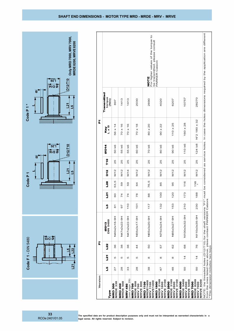
33RCOe 2401/01.05
The specified data are for product description purposes only and must not be interpreted as warranted characteristic in a
legal sense. All rights reserved. Subject to revision.
SHAFT END DIMENSIONS - MOTOR TYPE MRD - MRDE - MRV - MRVE
Co
de
P 1
Co
de F
1 -
DIN
54
80
noi
sr
eV
1F
1F
1F
1F
1F
1P
1P
1P
1P
1P
ep
yT
ep
yT
ep
yT
ep
yT
ep
yT
5L
5L
5L
5L
5L
12
L1
2L
12
L1
2L
12
L2
2L
22
L2
2L
22
L2
2L
31
DØ
31
DØ
31
DØ
31
DØ
31
DØ NI
D0
84
55
L5
L5
L5
L5
L1
2L
12
L1
2L
12
L1
2L
62
L6
2L
62
L6
2L
62
L2
1D
21
D2
1D
21
D2
1D
01
T0
1T
01
T0
1T
01
T4
1D
Ø4
1D
Ø4
1D
Ø4
1D
Ø4
1D
Øy
eK
ye
Ky
eK
ye
Ky
eK
Bx
L
de
tti
ms
na
rT
de
tti
ms
na
rT
de
tti
ms
na
rT
de
tti
ms
na
rT
de
tti
ms
na
rT
eu
qr
ot
)m
N(
ET
ON
ET
ON
ET
ON
ET
ON
ET
ON
ote
uqr
ote
htf
os
eul
av
re
hgi
hr
oF
tlu
sn
oc
es
ael
p,
detti
ms
nart
eb
RE
KR
AP
in
ozl
aC
00
3D
RM
00
3D
RM
00
3D
RM
00
3D
RM
00
3D
RM
03
3E
DR
M7
25
63
H9-
81
x2
x0
4N
18
06
5,3
52
1M
52
6k
05
41
x6
57
98
05
4D
RM
05
4D
RM
05
4D
RM
05
4D
RM
05
4D
RM
00
5E
DR
M8
25
83
H9-
22
x2
x7
4N
79
47
95
21
M5
26
k5
56
1x
07
31
41
05
4V
RM
05
4V
RM
05
4V
RM
05
4V
RM
05
4V
RM
)9
2e
ga
pe
es(
33
58
3H
9-2
2x
2x
74
N0
11
47
95
41
M5
26
k5
56
1x
07
31
41
00
7D
RM
00
7D
RM
00
7D
RM
00
7D
RM
00
7D
RM
00
8E
DR
M0
07
VR
M0
08
EV
RM
82
54
4H
9-7
1x
3x
55
N1
01
87
46
21
M5
26
k0
68
1x
07
03
02
00
11
DR
M0
01
1D
RM
00
11
DR
M0
01
1D
RM
00
11
DR
M0
04
1E
DR
M0
01
1V
RM
00
41
EV
RM
83
80
5H
9-0
2x
3x
56
N7
11
88
5,6
72
1M
52
6k
07
02
x0
80
96
2
00
81
DR
M0
08
1D
RM
00
81
DR
M0
08
1D
RM
00
81
DR
M0
01
2E
DR
M0
08
1V
RM
00
12
EV
RM
74
87
5H
9-4
2x
3x
57
N2
31
00
15
82
1M
52
6k
08
22
x0
90
20
4
00
82
DR
M0
08
2D
RM
00
82
DR
M0
08
2D
RM
00
82
DR
M0
01
3E
DR
M0
08
2V
RM
00
13
EV
RM
84
82
6H
9-7
2x
3x
58
N3
51
02
15
92
1M
52
6k
09
52
x0
11
70
26
00
54
DR
M0
05
4D
RM
00
54
DR
M0
05
4D
RM
00
54
DR
M0
04
5E
DR
M0
05
4V
RM
00
45
EV
RM
05
41
86
H9-
23
x3
x0
01
N0
12
37
16
11
21
M5
26
k0
11
82
x0
61
75
70
1
00
07
DR
M0
00
7D
RM
00
07
DR
M0
00
7D
RM
00
07
DR
M0
02
8E
DR
M0
00
7V
RM
00
28
EV
RM
05
41
67
H9-
53
x3
x0
11
N0
32
88
18
31
*2
1M
52
8b
42
12
3x
08
12
°N
07
28
2
tn
ereffi
der
an
oita
cilp
pa
eht
yb
deri
uq
ers
noi
sn
emi
ds
elo
he
hte
sa
cnI
.s
elo
he
civr
es
sa
der
edi
sn
oc
eb
ts
um
"1
P"s
noi
sre
vtf
ah
se
htr
of)
01
T/2
1D(
sel
oh
de
da
erht
eht
:E
TO
Nt
cat
no
ce
sel
p,
ev
ob
aer
eh
det
sils
en
oe
htm
orfR
EK
RA
P.i
no
zla
Cs
ye
ko
wts
ed
ulc
nin
ois
ne
mid
sih
T*
Co
de P
1 *
On
ly M
RD
7000, M
RV
7000,
MR
DE
8200, M
RV
E 8
200

The specified data are for product description purposes only and must not be interpreted as warranted characteristic in a
legal sense. All rights reserved. Subject to revision.
34RCOe 2401/01.05
COMPONENTS FOR SPEED CONTROL - MOTOR TYPE MRD - MRDE - MRV - MRVE
MECHANICAL
TACHOMETER DRIVE
TACHOGENERATOR
DRIVE
ENCODERDRIVE
INCREMENTAL ENCODER
DIMENSIONS
encoder
encoder drive flangeprotection
(see page 31)
Female connector included in the supply
α = 54° for the motor types MRD 300, MRDE 330
α =45° for the other types
α
( ) * Motor MRD 300, MRDE 330
Code "C1" Code "T1" Code "Q1"
2x M8x45 (2x M8x50)* 2x M8x45 (2x M8x50)* 2x M8x30 (2x M8x35)*
(62)**

35RCOe 2401/01.05
The specified data are for product description purposes only and must not be interpreted as warranted characteristic in a
legal sense. All rights reserved. Subject to revision.
COMPONENTS FOR SPEED CONTROL - MOTOR TYPE MOTOR TYPE MRD - MRDE - MRV - MRVE
Encoder type: ELCIS mod. 478
Supply voltage: 8 to 24 Vcc
Current consumption: 120 mA max
Current output: 10 mA max
Output signal: A phase- MONODIRECTIONAL
A and B phase BIDIRECTIONAL
Response frequency: 100 KHz max
Number of pulses: 500 (others on request - max 2540)
Slew speed: Always compatible with maximum
motor speed
Operating temperature range: from 0 to 70 °C
Storage temperature range: from -30 to +85 °C
Ball bearing life: 1.5x10⁹ rpm
Weigth: 100 gr
Protection degree: IP 67 (with protection and
connector assembled)
Connectors:
MONODIRECTIONAL RSF3/0.5 M (Lumberg) male
RKT3-06/5m (Lumberg) female
BIDIRECTIONAL RSF4/0.5 M (Lumberg) male
RKT4-07/5m (Lumberg) female
Note: Female connectors cable length equal to 5 m.
INCREMENTAL ENCODER
TECHNICAL DATA
Monodirectional
4 3 3 4
1 1
4 3 3 4
1 1
1 1 1
4 4
1
4 4
3 3 3 3
2 2
Femaleconnector
Maleconnector
Maleconnector
INCREMENTAL ENCODER
CONNECTION DIAGRAMS
Bidirectional
2 2
Femaleconnector
noitcnufdnaseriwroloC noitcnufdnaseriwroloC noitcnufdnaseriwroloC noitcnufdnaseriwroloC noitcnufdnaseriwroloC
11111 nworB nworB nworB nworB nworB )cdV42ot8(ylppuSrewoP
22222 etihW etihW etihW etihW etihW )ccV42-Am01XAM(esahpBtuptuO
33333 eulB eulB eulB eulB eulB )cdV0(ylppuSrewoP
44444 kcalB kcalB kcalB kcalB kcalB )ccV42-Am01XAM(esahpAtuptuO

The specified data are for product description purposes only and must not be interpreted as warranted characteristic in a
legal sense. All rights reserved. Subject to revision.
36RCOe 2401/01.05
ELECTRONIC DISPLACEMENT REGULATOR “RCE“- MOTOR TYPE MRD - MRDE - MRV - MRVE
RCE
USING GENERALITIESThe electronic regulator type RCE is designed
to be mounted on board of the motors type
“MRV/MRVE”, to control their displacement
in relation to a reference value of:
- displacement
- pressure
- speed
The RCE regulator is of the bi-directional ON-
OFF type, with successive integratory pulses.
It is mounted directly on a 4 way, 3 position
solenoid valve (CETOP size 6) which pilots the
displacement variation of the motor.
The power supply is 24 V DC or 24 V AC
rectified.
TECHNICAL DATA
Supply Voltage: 24 Vcc ± 10%rectified (Vmax. peak 35 V)
Max power needed: 35 W (60 W if you use the solenoid output:
SOLENOID C)
Referenced voltage: 0 - 10 Vcc (range 2 - 10 Vcc)
Displacement output signal: 2 - 10 Vcc
Pressure - speed output signal: 0 - 10 Vcc
Regolation and speed aptitute
pulse command: 12 - 24 Vcc (opto-insulated input)
Galvanic insulation between power and control circuits
Reversal of input polarity protection
Output power with self proofed MOSFET
IP 64 protection
Complying with standard CEE
DIMENSION and Data
1 Elettronic unit RCE/I-20 2 Middle plate3 PARKER DENISON valve 4 Double metering valve VDD
5 House case fixing screw
� �
�
�
������
���
���5�
��
� �5�
�
�
�
�
�

37RCOe 2401/01.05
The specified data are for product description purposes only and must not be interpreted as warranted characteristic in a
legal sense. All rights reserved. Subject to revision.
�
6�47��1���71���+�� ����
����8�
�1���71�/.7/�
�����
)�(6
�1���71��1.��87��1
��
����1��9%"�+�%,,:
������;����*�8��4-.������
�;
��
ELECTRONIC DISPLACEMENT REGULATOR “RCE“- MOTOR TYPE MRD - MRDE - MRV - MRVE
RCECIRCUIT FOR VARIABLE DISPLACEMENT MOTOR
DESCRIPTION The circuits of the regulator are powered through a DC/DC converter having 15 V DCoutput, so to obtain a total galvanic separation from the 24 V DC power lines. The inputreference signal to the regulator has been set in the range 2¸10 V DC, as for the output ofthe regulated values (displacement, pressure, speed). Three internal led show the commandcondition (+ or -). The pilot oil is dosed at each pulse by a specific dual metering valve type“VDD”, fitted beneath the solenoid valve. In relation to the parameter that it is wished tokeep under control by acting on the motor displacement, the RCE/I regulator can allow 3different regulation modes.
CONSTANT DISPLACEMENT MODE The hydraulic motor is equipped with an inductive (TEC) displacement transducer poweredby the regulator, which statically reads and saves the current displacement position at eachmotor revolution.Through special built-in valves, the motor keeps the set displacement position constant.Due to an intrinsic feature of radial-piston motors, the tendency under load is to movetoward maximum displacement.Thus the function of the regulator is to restore the original setting with an external voltagereference (range 2¸10 V DC from min. displ. to max displacement).The precision of the actual displacement value is approximately + 2¸3% over the ratedvalue set.For remote reading of the displacement a 2¸10 V DC output signal is provided, almostlinear in the range of the motor displacement variation.To quickly change from one value to another of the set displacement, a special opto-insulated input circuit may be activated in transitory mode with a 24 V DC signal.To enable the regulator only when the motor is running, it is necessary to activate a specialopto-insulated input circuit with a 24 V DC signal simultaneously with the start command;an internal trimmer allows a short enabling delay to be inserted if desired.The regulator is normally set to perform stable adjustments up to a minimum speed of 60r.p.m.For lower speeds, to approximately 6 r.p.m., it is necessary to use an internal multiple-turntrimmer to modify the pause length between the control pulses.The pause length must be greater than the time required by the motor to complete one turn,this is to permit the displacement position read by the transducer at each shaft revolution to
be updated in the memory.

The specified data are for product description purposes only and must not be interpreted as warranted characteristic in a
legal sense. All rights reserved. Subject to revision.
38RCOe 2401/01.05
ELECTRONIC DISPLACEMENT REGULATOR “RCE“- MOTOR TYPE MRD - MRDE - MRV - MRVE
CONSTANT WORKINGPRESSURE MODE When the motor is used in systems equipped with hydraulic accumulators and the torque
required by the motor may vary in relation to the process characteristics, the displacement iscontrolled in relation to the working pressure set for the motor, so that the working pressureremains constant as the required torque varies.The constant pressure regulation can be achieved for torque variations within the displacementvariation ratio allowed by the motor.The hydraulic circuit that feed the motor must include a pressure transducer that may bepowered by the regulator itself with a voltage of 15 V DC and a signal output of 0¸10 V DC or4¸20 mA. The hydraulic motor is equipped with built-in valves, to maintain the displacement, aswell as with the displacement transducer if it is wished to read the actual displacement duringtorque changes (by processing the displacement signal together with the pressure and speedsignals, it is possible to determine the torque and absorbed power). The pressure setting isachieved by means of an external signal in the range 0¸10 V DC (2¸ 10 V DC); the 10 V valuemust correspond to the full scale value (10 V or 20 mA) of the pressure transducer. The min.acceptable reference value is 2 V DC. During the startup transitory, the regulator remainsdisabled for an adjustable period of time (internal trimmer).Also in this case the regulator is enable with a 24 V DC input signal.Even with frequent start-stop cycles, the regulator can change the motor displacement to adaptit to the average pressure value saved during the running cycle.The saved pressure signal can be read remotely, again in the range 0¸10 V DC. A third 24 V DCpower output is available on the regulator to simultaneously energize a 2-way solenoid valve ofthe type with a conical diaphragm, which intercepts the pilot oilupstream the 4-way solenoidvalve.
CONSTANT SPEED MODE If multi-stage fixed displacement pumps are used to drive the motor, in certain conditions it isnecessary to drain off the excess delivery in relation to the set motor speed.In order to avoid this dissipation, it is possible to use a variable-displacement motor which wouldabsorb the excess delivery by adjusting its displacement. The regulator in this case accents thespeed signal and compares it to the reference value; when the motor speed exceeds the set value,the regulator increases the displacement until the excess delivery provided by the pump isabsorbed; at the same time, the working pressure is proportionally reduced, to the advantage ofthe life of the components of the system (pump, motor, etc.).This provides a simple speed regulating system without energy dissipation, since the circuitincludes neither flow regulator valves nor drainage valves. The speed signal saved is alsoavailable as output signal for remote reading, again in the field of 0¸10 V DC; this signal may beuseful for detecting the maximum speed reached when the motor running cycle is very short (<2sec). Here again, the regulation is enable by activating the special 24 V DC input circuit; thecommand may be delayed by the time the motor needs to accelerate in order to reach the ratedspeed. If it is wished to switch quickly the speed from one value to another, a special input maybe activated with a 24 V DC signal in transitory mode. The precision attainable through thissystem varies: it is approximately ± 2% on the fullscale value with the motor at maximumdisplacement; at minimum displacement the precision is slightly lower.
Pressure - speed
Input
4 ÷ 20 mA
0 ÷ 10 VccP1
offset setting(displacement output)
P3
Control delay
JP1 (function)
P4
Pulse length setting
P2
Full scale setting
(displacement Output)
Constant
Pressure - speed
Constant displacement Solenoid output reversal controlMIN
MAX
JP3 (sensitivity)

39RCOe 2401/01.05
The specified data are for product description purposes only and must not be interpreted as warranted characteristic in a
legal sense. All rights reserved. Subject to revision.
ELECTRONIC DISPLACEMENT TRANSDUCER - MOTOR TYPE MRD - MRDE - MRV - MRVE
ELECTRONIC DISPLACEMENTTRANSDUCERTECHNICAL DATA
Max cont. pressure: 2,5 bar
Supply voltage: 18 - 24 Vdc - stab. ± 0,5%
Current consuption: 10 mA
Output current: 1 - 6 mA
Working temperature range: da 0 a 60°C
Load impedance: 1 KΩ
Reading displacement range: 1:3
protection degree: IP 68
Precision F.S. ± 1%
ELECTRONIC DISPLACEMENTTRANSDUCER
DIMENSIONS
ROTOM ROTOM ROTOM ROTOM ROTOMEPYT
AAAAA BBBBB ααααα
054VRM 054VRM 054VRM 054VRM 054VRM 801 6,531 '03°21
007VRM 007VRM 007VRM 007VRM 007VRM008EVRM
3,511 8,741 °21
0011VRM 0011VRM 0011VRM 0011VRM 0011VRM0041EVRM
6,421 971 °5
0081VRM 0081VRM 0081VRM 0081VRM 0081VRM0012EVRM
3,231 012 °5
0082VRM 0082VRM 0082VRM 0082VRM 0082VRM0013EVRM
2,141 5,732 °5
0054VRM 0054VRM 0054VRM 0054VRM 0054VRM0045EVRM
8,551 662 °7
0007VRM 0007VRM 0007VRM 0007VRM 0007VRM0028EVRM
002 262 '03°6
0""@ 66@ 22@
����� ��������
0� �����5�� �
=/:&;�*))98�@
�>;8
�A)��� ���%���13������� ��
/� �������0� �����������0
0�(
����
/� ����������
���%�
B
0""@
��0"@
$������������������������������� ��2�"#23�C����������1��
�
��
����
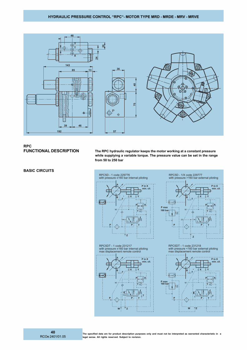
The specified data are for product description purposes only and must not be interpreted as warranted characteristic in a
legal sense. All rights reserved. Subject to revision.
40RCOe 2401/01.05
HYDRAULIC PRESSURE CONTROL “RPC“- MOTOR TYPE MRD - MRDE - MRV - MRVE
RPC
FUNCTIONAL DESCRIPTION The RPC hydraulic regulator keeps the motor working at a constant pressure
while supplying a variable torque. The pressure value can be set in the range
from 50 to 250 bar
BASIC CIRCUITS
"�""""
��
��
�
�
�
�
&
��
��
���
��
���
��
���
�� ��
'&*!=8�C�0������120107%��� ��������D06"�������������� ����������� �����������������������
'&*!=�C�05E������11<444%��� ��������F06"�������������� �����
'&*!=8�C�0������120104%��� ��������D06"������������� ����������� �����������������������
'&*!=�C�0������11<446%��� ��������D06"������������� �����
<=
�
�
�
�
�
�
�
�
�
��������*���-*
�
�
�
�
��
�
<
� �
�
��������*���-*
�
= <
�
�
�� �2.1���.>
�
�
�
�
��
�
�
�
���.>�� �2.1
�
<
�
�
�
�
� �
�
��������*���-*
�
��������*���-*
� �

41RCOe 2401/01.05
The specified data are for product description purposes only and must not be interpreted as warranted characteristic in a
legal sense. All rights reserved. Subject to revision.
HYDRAULIC PRESSURE CONTROL “RPC“- MOTOR TYPE MRD - MRDE - MRV - MRVE
RPC
USING GENERALITIESA variable torque and speed, constant power
system can be obtained by using the MRD-MRDE
motor provided with the RPC constant pressure
regulator along with a fixed displacement pump.
REGULATION SCHEME
HYDRAULIC CIRCUIT
RPC = motor constant pressure regulatorP = Q x p max = constantM
1 x n
1 = M
2 x n
2 = constant
RPC
USING GENERALITIESBy replacing the fixed displacement pump with a
variable one provided with a constant regulator, it
is possible to obtain an enlargement of the torque
and speed regulation range to constant power.
REGULATION SCHEME
HYDRAULIC CIRCUIT
RPCp = pump constant power regulatorRPCm = motor constant pressure regulatorP = M
1 x n
1 = M
2 x n
2 = constant
��4
��4
*�*)*��
��
?
��
��
*�*)*4 *�*)*�
?
��
��
��
��
��@.1�.2-�8��4-.����������1
�������.���4�A�1
����*�����1�8��4-.������
?�47�4
������1
���.>*�����*
4�47�4
������1
���.>�����1
����������1
�.>�����1�8��4-.������
�������.��
4��.>�47�4�41���71����*�����1�8��4-.������1�/7-.��1��4�1.���/�4����
?�47�4
������1
���.>*�����*
4�47�4
������1
��0�>�88��4-.����������1
�����*�����1
@.1�.�����1.�/���047�4�8�-�@�13
@.1�.�����1.�/���0�����1��4��8
���1�.����0��!�
��1B7�(�4��8�1.�/�
�����.���41���71��1�/7-.����
1.�/���0��!��@.1�.2-�
8��4-.�����������1
47�4������.���4�A�1
1�/7-.����1.�/�
�����*�47�4
���.>*�47�4

The specified data are for product description purposes only and must not be interpreted as warranted characteristic in a
legal sense. All rights reserved. Subject to revision.
42RCOe 2401/01.05
PIPE CONNECTION FLANGES - MOTOR TYPE MRD - MRDE - MRV - MRVE
STANDARD CONNECTION FLANGECode “C1“
Flange is supplied complete with screws and seals.
SAE CONNECTION FLANGECode “S1“Code “T1“Code “G1“Code “L1“
Permitted up to 6000 PSI
Flange is supplied complete with screws and seals. FPM seals enquiry.
BSP threads to ISO 228/1
EDRM-DRM EDRM-DRM EDRM-DRM EDRM-DRM EDRM-DRMEVRM-VRM
DDDDD)PSB(
HHHHHGNIREDRO GNIREDRO GNIREDRO GNIREDRO GNIREDRO
EDOC
RBN RBN RBN RBN RBN
GNIREDRO GNIREDRO GNIREDRO GNIREDRO GNIREDROEDOC
MPF MPF MPF MPF MPF
033-003 033-003 033-003 033-003 033-003 "4/3 83 890262 493922
005-054 005-054 005-054 005-054 005-054008-007
"4/11 93 980262 593922
0041-0011 0041-0011 0041-0011 0041-0011 0041-00110012-0081
"2/11 54 390262 693922
0013-0082 0013-0082 0013-0082 0013-0082 0013-0082 "2/11 95 275462 793922
0045-0054 0045-0054 0045-0054 0045-0054 0045-00540028-0007
"2 85 427272 893922
EDRM-DRM EDRM-DRM EDRM-DRM EDRM-DRM EDRM-DRMEVRM-VRM
EAS EAS EAS EAS EASISP
DDDDD
HHHHH IIIII XXXXX YYYYY
CIRTEM CIRTEM CIRTEM CIRTEM CIRTEM CNU CNU CNU CNU CNU
""""" mmmmmmmmmm T/Z T/Z T/Z T/Z T/ZGNIREDRO GNIREDRO GNIREDRO GNIREDRO GNIREDRO
EDOC
RBN RBN RBN RBN RBNZZZZZ TTTTT
GNIREDRO GNIREDRO GNIREDRO GNIREDRO GNIREDROEDOC
RBN RBN RBN RBN RBN
033-003 033-003 033-003 033-003 033-003 0005 "4/3 91 83 55 2,22 6,74 52/01M 592772 61-"8/3 52 533322
005-054 005-054 005-054 005-054 005-054008-007
0005 "1 52 93 06 2,62 4,25 52/01M 792772 61-"8/3 52 633322
0041-0011 0041-0011 0041-0011 0041-0011 0041-00110012-0081
0004 "4/11 13 54 57 2,03 7,85 52/01M 992772 41-"61/7 03 733322
0006 "1 52 54 17 8,72 51,75 22/21M 661032 41-"61/7 03 290243
0013-0082 0013-0082 0013-0082 0013-0082 0013-00820003 "2/11 73 95 68 7,53 8,96 03/21M 103772 31-"2/1 03 833322
0006 "2/11 73 95 001 5,63 4,97 03/61M 861032 11-"8/5 53 860943
0045-0054 0045-0054 0045-0054 0045-0054 0045-00540028-0007
0003 "2 05 85 211 9,24 8,77 03/21M 303772 31-"2/1 03 933322
0006 "2 05 85 611 54,44 28,69 53/02M 071032 01-"4/3 83 745243

43RCOe 2401/01.05
The specified data are for product description purposes only and must not be interpreted as warranted characteristic in a
legal sense. All rights reserved. Subject to revision.
COUPLINGS - KEY ADAPTERS - MOTOR TYPE MRD - MRDE - MRV - MRVE
COUPLINGS
1 For standard male splined shaft version "N1" (see page 26).
2ADAPTERS WITH KEY
1 For standard male splined shaft version "N1" (see page 26).2 Key to DIN 6885
1
1
EDRM-DRM EDRM-DRM EDRM-DRM EDRM-DRM EDRM-DRMEVRM-VRM
GNIREDRO GNIREDRO GNIREDRO GNIREDRO GNIREDROEDOC
AAAAA BBBBB CCCCC11H 11H 11H 11H 11H
DDDDD EEEEE FFFFF GGGGG
033-003 033-003 033-003 033-003 033-003 202564 531 17 94 06 46 51 54
005-054 005-054 005-054 005-054 005-054 102564 551 08 55 86 86 5,81 5,55
008-007 008-007 008-007 008-007 008-007 002564 171 09 16 57 08 91 95
0041-0011 0041-0011 0041-0011 0041-0011 0041-0011 587464 681 601 37 5,88 5,58 02 5,56
0012-0081 0012-0081 0012-0081 0012-0081 0012-0081 991564 422 811 38 89 701 22 87
0013-0082 0013-0082 0013-0082 0013-0082 0013-0082 891564 562 231 39 211 721 32 79
0045-0054 0045-0054 0045-0054 0045-0054 0045-0054 296474 553 051 311 621 561 03 041
0028-0007 0028-0007 0028-0007 0028-0007 0028-0007 445224 093 591 621 041 581 83 741
EDRM-DRM EDRM-DRM EDRM-DRM EDRM-DRM EDRM-DRMEVRM-VRM
GNIREDRO GNIREDRO GNIREDRO GNIREDRO GNIREDROEDOC
RRRRR ddddd IIIII DDDDD 6k6k6k6k6k LLLLL bbbbb tttttYEK YEK YEK YEK YEK
5886NID
033-003 033-003 033-003 033-003 033-003 811172 84x24x8A 3,84 51 07 06 41 5,37 65x9x41
005-054 005-054 005-054 005-054 005-054 911172 45X64x8A 3,45 5,81 08 57 61 48 07x01x61
008-007 008-007 008-007 008-007 008-007 021172 06x25x8A 3,06 91 09 08 81 49 07x11x81
0041-0011 0041-0011 0041-0011 0041-0011 0041-0011 121172 27x26x8A 3,27 02 501 89 02 5,901 09x21x02
0012-0081 0012-0081 0012-0081 0012-0081 0012-0081 221172 28x27x01A 3,28 22 811 811 22 321 011x41x22
0013-0082 0013-0082 0013-0082 0013-0082 0013-0082 321172 29x28x01A 3,29 92 031 841 52 531 041x41x52
0045-0054 0045-0054 0045-0054 0045-0054 0045-0054 917272 211x201x01A 3,211 03 061 881 82 661 081x61x82
0028-0007 0028-0007 0028-0007 0028-0007 0028-0007 674322 521x211x01A 6,521 83 581 881 54 591 081x52x54

The specified data are for product description purposes only and must not be interpreted as warranted characteristic in a
legal sense. All rights reserved. Subject to revision.
44RCOe 2401/01.05
HOLDING BRAKE UNIT DIMENSIONS - MOTOR TYPE MRD - MRDE - MRV - MRVE
EPYTEKARB EPYTEKARB EPYTEKARB EPYTEKARB EPYTEKARB 003B 003B 003B 003B 003B 054B 054B 054B 054B 054B 007B 007B 007B 007B 007B 0011B 0011B 0011B 0011B 0011B 0081B 0081B 0081B 0081B 0081B 0082B 0082B 0082B 0082B 0082B
EPYTROTOM EPYTROTOM EPYTROTOM EPYTROTOM EPYTROTOMEDRM-DRMEVRM-VRM
033-003 033-003 033-003 033-003 033-003 005-054 005-054 005-054 005-054 005-054 008-007 008-007 008-007 008-007 008-007 0041-0011 0041-0011 0041-0011 0041-0011 0041-0011 0012-0081 0012-0081 0012-0081 0012-0081 0012-0081 0013-0082 0013-0082 0013-0082 0013-0082 0013-0082
Same dimensionsstandard male splinedshaft version "N1"(see page 26)
ααααα1, ααααα2 Corresponding angles to the release ports 1 and 2, to case the drain ports 1 and 2
Release portsCase drain ports
Release portsCase drain ports
Case drain portsRelease ports
øD
2
D7
L1
L11
D1
L10
L6
D6L7
L5
L4
øD
4h
8
øD
9N
°5
HO
LE
S
L2
L3
øD
5
D1
2
T10
L21L22
øD
3
øD
13
EPYTEKARB EPYTEKARB EPYTEKARB EPYTEKARB EPYTEKARB 1L1L1L1L1L 2L2L2L2L2L 3L3L3L3L3L 4L4L4L4L4L 5L5L5L5L5L 6L6L6L6L6L 7L7L7L7L7L 01L 01L 01L 01L 01L 11L 11L 11L 11L 11L 12L 12L 12L 12L 12L 22L 22L 22L 22L 22L 1D1D1D1D1D 2D2D2D2D2D 3D3D3D3D3D 4D4D4D4D4D 8h8h8h8h8h 5D5D5D5D5D 6D6D6D6D6D 7D7D7D7D7D 9D9D9D9D9D 21D 21D 21D 21D 21D 31D 31D 31D 31D 31D 01T 01T 01T 01T 01T aaaaa11111 aaaaa22222
003B 003B 003B 003B 003B 631 - 52 51 18 24 5,93 12 68 06 64
23egapeeselbitapmoc1D1Nedoc
652 232 571 - "4/1G '8/3G 5,01 21M
egapees33-23
edoc1F-1D-1N
82 '03°22 '03°22
054B 054B 054B 054B 054B 741 - 72 51 79 5,94 63 42 001 47 5,65 692 662 091 - "4/1G '8/3G 5,31 21M 82 '03°22 '03°22
007B 007B 007B 007B 007B 271 - 82 51 101 55 64 52 501 87 26 023 092 022 - "4/1G '8/3G 5,31 21M 82 '03°22 '03°22
0011B 0011B 0011B 0011B 0011B 881 02 62 42 711 17 5,35 84 021 88 27 063 033 052 021 "4/1G '2/1G 51 21M 82 °0 °0
0081B 0081B 0081B 0081B 0081B 612 - 82 12 231 5,36 5,85 43 531 001 97 324 083 092 - "4/1G '2/1G 5,71 21M 82 '03°22 '03°22
0082B 0082B 0082B 0082B 0082B 362 - 03 42 351 78 76 5,24 561 021 99 494 044 533 - "4/1G '2/1G 91 21M 82 '03°22 '03°22

45RCOe 2401/01.05
The specified data are for product description purposes only and must not be interpreted as warranted characteristic in a
legal sense. All rights reserved. Subject to revision.
HOLDING BRAKE TECHNICAL DATA - MOTOR TYPE MRD - MRDE - MRV - MRVE
TECHNICAL DATA (For operation outside these parameters, please consult PARKER Calzoni)
SCITSIRETCARAHC SCITSIRETCARAHC SCITSIRETCARAHC SCITSIRETCARAHC SCITSIRETCARAHC003B 003B 003B 003B 003B 054B 054B 054B 054B 054B 007B 007B 007B 007B 007B 0011B 0011B 0011B 0011B 0011B 0081B 0081B 0081B 0081B 0081B 0082B 0082B 0082B 0082B 0082B
EUQROTGNIKARBCITATS EUQROTGNIKARBCITATS EUQROTGNIKARBCITATS EUQROTGNIKARBCITATS EUQROTGNIKARBCITATS mNmNmNmNmN 0081 0562 0004 0026 00411 00171
EUQROTGNIKARBCIMANYD EUQROTGNIKARBCIMANYD EUQROTGNIKARBCIMANYD EUQROTGNIKARBCIMANYD EUQROTGNIKARBCIMANYD mNmNmNmNmN 0021 0541 0022 0024 0526 00021
ERUSSERPESAELER ERUSSERPESAELER ERUSSERPESAELER ERUSSERPESAELER ERUSSERPESAELER rab rab rab rab rab 82 72 72 72 03 03
ERUSSERPGNITAREPO.XAM ERUSSERPGNITAREPO.XAM ERUSSERPGNITAREPO.XAM ERUSSERPGNITAREPO.XAM ERUSSERPGNITAREPO.XAM rab rab rab rab rab 024 024 024 024 024 024
STRAPGNITATORFOAITRENIFOTNEMOM STRAPGNITATORFOAITRENIFOTNEMOM STRAPGNITATORFOAITRENIFOTNEMOM STRAPGNITATORFOAITRENIFOTNEMOM STRAPGNITATORFOAITRENIFOTNEMOM mgK mgK mgK mgK mgK 22222 2600,0 920,0 340,0 160,0 02,0 72,0
THGIEW THGIEW THGIEW THGIEW THGIEW gKgKgKgKgK 93 45 47 001 851 262
EVRM-VRM-EDRM-DRMEPYTROTOM EVRM-VRM-EDRM-DRMEPYTROTOM EVRM-VRM-EDRM-DRMEPYTROTOM EVRM-VRM-EDRM-DRMEPYTROTOM EVRM-VRM-EDRM-DRMEPYTROTOM 003033
054005
007008
00110041
00810012
00820013
CODE Example: BRAKE - B 450 N1 N1 V1 **
003B 003B 003B 003B 003B "D"ezisrotomrofekarB
054B 054B 054B 054B 054B "E"ezisrotomrofekarB
007B 007B 007B 007B 007B "F"ezisrotomrofekarB
0011B 0011B 0011B 0011B 0011B "G"ezisrotomrofekarB
0081B 0081B 0081B 0081B 0081B "H"ezisrotomrofekarB
0082B 0082B 0082B 0082B 0082B "I"ezisrotomrofekarB
1. BRAKE - B 450 N1 N1 V1 **
********** inozlaCREKRAPotdevreserecapS
1N1N1N1N1N liolarenim:RBN
*1V *1V *1V *1V *1V slaesMPF
1U1U1U1U1U )ekarbrof(laestfahsoN
inozlaCREKRAPtcatnocesaelp* inozlaCREKRAPtcatnocesaelp* inozlaCREKRAPtcatnocesaelp* inozlaCREKRAPtcatnocesaelp* inozlaCREKRAPtcatnocesaelp*
4. BRAKE - B 450 N1 N1 V1 **
1N1N1N1N1N )03egapees(3645NIDxeenilpS
*1D *1D *1D *1D *1D )03egapees(0845NIDenilpS
*1F *1F *1F *1F *1F )13egapees(0845NIDenilpselameF
inozlaCREKRAPtcatnocesaelp* inozlaCREKRAPtcatnocesaelp* inozlaCREKRAPtcatnocesaelp* inozlaCREKRAPtcatnocesaelp* inozlaCREKRAPtcatnocesaelp*
2. BRAKE - B 450 N1 N1 V1 **
5. BRAKE - B 450 N1 N1 V1 **
BRAKE TYPE
OUTPUT SHAFT
SEALS
SPECIAL
1N1N1N1N1N )03egapees(1NepytrotomroftfahswolloH
1D1D1D1D1D )03egapees(1DepytrotomroftfahswolloH
3. BRAKE - B 450 N1 N1 V1 **
INPUT SHAFT

The specified data are for product description purposes only and must not be interpreted as warranted characteristic in a
legal sense. All rights reserved. Subject to revision.
46RCOe 2401/01.05
�
�
�
�
�����
�
�
�
�����
� �
� �
��
��
�
��
�
� �
INSTALLATION NOTES - MOTOR TYPE MRD - MRDE - MRV - MRVE
Mounting
Any mounting position- Note the position of the case drain port
(see below)
Install the motor properly- Mounting surface must be flat and resistant
to bending
Min. tensile strength of mounting screws to DIN 267Part 3 class 10.9
- Note the prescribed fastening torque
Pipes, pipe connections
Use suitable screws!- Depending on type of motor use either
threaded or flange connection
Choose pipes and hoses suitable for the installation- Please note manufacturing data!
Before operation fill with hydraulic fluid- Use the prescribed filter!
*
*)
Coupling
- Mounting with screws- Use threaded bore in
the drive shaft- Take apart with extractor
NOTE: Two of the mounting screws must be precisely located/fitted if operation is started and stopped frequently or if high reversible
frequencies exist.
Curved tooth couplinghub
Screw to remove thecoupling hub
Note: Position the case drain pipe, so thatthe motor cannot run empty.
T = SealY = Motor housing feeding line
= Bleed
DRAIN AND FLUSHING LINK INSTALLATION EXAMPLES
Installation instructions for motorsof the series "MRD - MRDE - MRV - MRVE"
Installation instructions for motorsof the series "MRD - MRDE - MRV - MRVE with brakes"
Bleed point
(release to bleed)
Low pressure case drain returns to tank. Low pressure case drain returns to tank.
Motors without shaft seal used with brake
Tank located in higher position
N° 2 lockingscrew forbleed point(on enquiry)
*)Special designs for applications, where the equipmentneeds to be filled with oil.(e.g. in a salty atmosphere)
Flushing p max= 5 bar Flushing p max= 5 bar
Cooling circuit for high powercontinuous operation
Bleed screw(on enquiry)
Bleed point
Cooling circuit for high power continuous operation

47RCOe 2401/01.05
The specified data are for product description purposes only and must not be interpreted as warranted characteristic in a
legal sense. All rights reserved. Subject to revision.
ORDERING CODE - MOTOR TYPE MRD - MRDE - MRV - MRVE
SPECIAL
CODE Example: MRD 700 F 240 N1 M1 F1 N1 N **
DRM DRM DRM DRM DRM suounitnoc.xamrab052dradnats
EDRM EDRM EDRM EDRM EDRM suounitnoc.xamrab012dednapxe
VRM VRM VRM VRM VRM suounitnoc.xamrab052dradnats
EVRM EVRM EVRM EVRM EVRM suounitnoc.xamrab012dednapxe
1. MRD 700 F 240 N1 M1 F1 N1 N **
DDDDDedoc
DRM DRM DRM DRM DRM051D003
EDRM EDRM EDRM EDRM EDRM561D033
mC 3 1,403 1,251 4,233 2,661
EEEEEedoc
DRM DRM DRM DRM DRM522E054
EDRM EDRM EDRM EDRM EDRM052E005
VRM VRM VRM VRM VRM331E054
mC 3 6,154 8,522 9,794 9,842 6,154 5.331
FFFFFedoc
DRM DRM DRM DRM DRM042F007
EDRM EDRM EDRM EDRM EDRM072F008
VRM VRM VRM VRM VRM042F007
EVRM EVRM EVRM EVRM EVRM072F008
mC 3 9,607 6,732 2,408 2,072 9,607 6,732 2,408 2,072
GGGGGedoc
DRM DRM DRM DRM DRM083G0011
EDRM EDRM EDRM EDRM EDRM074G0041
VRM VRM VRM VRM VRM083G0011
EVRM EVRM EVRM EVRM EVRM074G0041
mC 3 8,5211 3,183 5,9631 9,364 8,5211 3,183 5,9631 9,364
HHHHHedoc
DRM DRM DRM DRM DRM006H0081
EDRM EDRM EDRM EDRM EDRM007H0012
VRM VRM VRM VRM VRM006H0081
EVRM EVRM EVRM EVRM EVRM007H0012
mC 3 6,9081 2,306 2,1902 0,796 6,9081 2,306 2,1902 0,796
IIIIIedoc
DRM DRM DRM DRM DRM039I0082
EDRM EDRM EDRM EDRM EDRM0301I0013
VRM VRM VRM VRM VRM039I0082
EVRM EVRM EVRM EVRM EVRM0301I0013
mC 3 0,2972 7,039 7,3013 6,4301 0,2972 7,039 7,3013 6,4301
LLLLLedoc
DRM DRM DRM DRM DRM0051L0054
EDRM EDRM EDRM EDRM EDRM0081L0045
VRM VRM VRM VRM VRM0051L0054
EVRM EVRM EVRM EVRM EVRM0081L0045
mC 3 7,2054 8,7941 2,1045 4,0081 7,2054 8,7941 2,1045 4,0081
MMMMMedoc
DRM DRM DRM DRM DRM0232M0007
EDRM EDRM EDRM EDRM EDRM0572M0028
VRM VRM VRM VRM VRM0232M0007
EVRM EVRM EVRM EVRM EVRM0572M0028
mC 3 2,7696 4,2232 4,6228 1,2472 2,7696 4,2232 4,6228 1,2472
2. MRD 700 F 240 N1 M1 F1 N1 N **
3. MRD 700 F 240 N1 M1 F1 N1 N **
4. MRD 700 F 240 N1 M1 F1 N1 N **
5. MRD 700 F 240 N1 M1 F1 N1 N **
7. MRD 700 F 240 N1 M1 F1 N1 N **
6. MRD 700 F 240 N1 M1 F1 N1 N **
8. MRD 700 F 240 N1 M1 F1 N1 N **
SERIES
SIZE & DISPLACEMENT
SHAFT
SPEED SENSOR OPTION
CONNECTION FLANGE
SEALS
ROTATION
1N1N1N1N1N )23egapees(3645NIDxeenilps
1D1D1D1D1D )23egapees((0845NIDenilps
1F1F1F1F1F )33egapees(0845NIDenilpselamef
1P1P1P1P1P )33egapees(yekhtiwtfahs
1B1B1B1B1B )23egapees(0553.S.Benilps
1N1N1N1N1N enon
1Q1Q1Q1Q1Q )43egapees(evirdredocne
1C1C1C1C1C )43egapees(evirdretemohcatlacinahcem
1T1T1T1T1T )43egapees(evirdrotarenegohcat
1M1M1M1M1M redocnesiclElatnemercniegapees()ver/eslup005( 43 )
lanoitcerid-inU
1B1B1B1B1B lanoitcerid-iB
1N1N1N1N1N liolarenimRBN
1F1F1F1F1F laestfahsrab51,RBN
1V1V1V1V1V slaesMPF
1U1U1U1U1U )ekarbrof(laestfahson
NNNNN )Bnitelni:WCC,Anitelni:WC(noitatordradnats
SSSSS )Anitelni:WCC,Bnitelni:WC(noitatordesrever
1N1N1N1N1N enon
1C1C1C1C1C )24egapees(inozlaCREKRAPdradnats
1S1S1S1S1S )24egapees(cirtemEASdradnats
1T1T1T1T1T )24egapees(CNUEASdradnats
1G1G1G1G1G )24egapees(cirtemisp0006EAS
1L1L1L1L1L )24egapees(CNUisp0006EAS
3S3S3S3S3S )13egapees(detargetnirotomcirtemEASdradnats
3G3G3G3G3G )13egapees(detargetnirotomcirtemisp0006EAS
********** inozlaCREKRAPotdevreserecapsSPECIAL

The specified data are for product description purposes only and must not be interpreted as warranted characteristic in a
legal sense. All rights reserved. Subject to revision.
48RCOe 2401/01.05
SALES AND SERVICE LOCATIONS WORLDWIDE - MOTOR TYPE MR - MRE
FOR INFORMATION ABOUT SALES AND SERVICE LOCATIONS PLEASE CONTACT:
Parker Calzoni S.r.l.
Via caduti di sabbiuno 15/1740011 Anzola dell’Emilia
Bologna – ItalyTel. +39.051.6501611Fax. +39.051.736221
e-mail: [email protected]
or visit the websites:
YOUR LOCAL PARKER CALZONI REPRESENTATIVE
www.parker.com
www.denisonhydraulics.com