Park Road Standards · 2019-05-13 · enhance visitor experience while pr oviding safe and...
52
D-217A F.llL NP6·Gct,e,al PARK ROAD STANDARDS PU:Asf RETURN TO: TECHNICAL INFORMATION rJ:'lm!D DEN\IER SERVICE CENTER ._,,,'I. NATIONAL PARK SERV I CE /
Transcript of Park Road Standards · 2019-05-13 · enhance visitor experience while pr oviding safe and...

D-217A F.llL
NP6·Gct,e,al
PARK ROAD STANDARDS
PU:Asf RETURN TO: TECHNICAL INFORMATION rJ:'lm!D DEN\IER SERVICE CENTER ._,,,'I. NATIONAL PARK SERVICE /

• THE PURPOSE OF PARK ROADS
Among all public resources, those of the National Park System are distinguished by their unique natural, historical, cultural and recreational qualities--values dedicated and set aside by law to be preserved for the benefit and enjoyment of people in such a manner as will leave them unimpaired for future generations.
Ideally, perhaps no road would be permitted to violate or despoil the sanctity of park resources. Pragmatically, the protection, use and enjoyment of these values in a world of modern technology has necessi-ta-t-e-d-- -t-h-e---e.n.e-r..o.achmeot of. _a _~ys_t!!m of public park roads. Today's visitors are no longer required, as ~arlj moforists to Y~llowstone · once were, to chain their cars to logs and turn over the keys to the superintendent. In most parks today, the basic means of providing for visitor access is the park road system. It is both a means and an end. It enables one visitor to reach his goal; for another, it is the goa 1.
The marked increase of park visitors in the latter half of the 20th century represe nts both a profound threat to park values and an extraordinary opportunity for those values to become more tangibly significant in each individual's recognition of our natural and cultural heritage.
• The fundamental purpose of national parks--bringing humankind and the environment into closer harmony--dictates that the quality of the park experience must be our primary concern. Full enjoyment of a national park visit depends on its being a safe and leisurely experience. The distinctive character of park roads plays a basic role in setting this essential unhurried pace. Consequently, park roads are designed with extreme care and sensitivity with respect to the terrain and environ-ment through wh ich they pass--they are laid lightly onto the land.
Each segment of every park road should relate to the resource it tra-verses in a meaningful way and should constitute an enjoyable and informative experience in itself while providing the visitor the utmost in visua l quality. Long tangents that encourage high speeds--and only fleeting views of "kinetic scenery•--should be avoided. The horizontal and vertical alignment and cross-section should respect the terrain, blending into the environs. A park road should be fundamen-tally designed to maintain an overall continuing sense of intimacy with the countryside or area through which it passes .
The purpose of park roads remains in sharp contrast to that of the Federal and State highway systems. Park roads are not intended to provide fast and convenient transportation; they are intended to
• 1

-enhance visitor experience while pr oviding safe and efficient accom -modation of park visitors and to serve essential management access needs. They are not, therefo r e, intended nor designed as con-tinuations of the State and Federal-aid network. Nor should they be designed or designated t o serve as connecting links to those systems . And within parks. no ro ad or other circulation system should be planned or designed me r ely as a device to link points of interest.
As stated on a brochure that was once given to visitors when they entered National Parks:
Park r oad s are f or l e fsurel y driving only. I f you are in a hurry, you might do we l l to take another route now, and come bac k whe n you have more t i me .
* * *
2

•
?
) \
f I
,
•
•
Table of Contents
Preface • . • • . i cknowledgements i i A
THE PURPOSE Of PARK ROADS • • . . . . . . 1
UNCTIONAL CLASSIFICATIONS OF PARK ROADS 3 FPark Road System • • • • . 3
Public Use Park Road . . • . . 3
Principal Park Road/Rural Parkway Connector Park Road Special Purpose Park Road
3
3
3 Primitive Park Road . . •
Administrative Park Roads • 4 Administrative Access Road Restricted Road • • • •
4 4
Urban Parkways & City Streets 4 Urban Parkway City Street • • • •
4 4
FUNDAMENTAL CONSIDERATIONS IN PARK ROAD DESIGN 7
PARK ROAD DESIGN STANDARDS Design Controls & Criteria 12
Design Volume . • • .Design Speed . . • .Design Vehicle • . • • . • . • .
. •
12 12 13
Inter-Relationship of Design Controls Design Elements • • . 18
Vertical Alignment 18 Grades • • • • •Vertical Curves . . . .General Considerations
18 19 21
Horizontal Alignment 21 Maximum Degree of Curvature • • • . • . .Superelevation Runoff & Transition Curves General Controls • . .
• 22 23 23
Sight Distance . . . • . . .
Stopping Sight Distance 24 Passing Sight Distance • . • . 26 Intersection Sight Distance 26
24
Intersections . .Number of Lanes Cross-Section • .Recreation Areas Bikeways Surface Type Surface Crown . .
. '
27 28 28 31 31 31 31
i i i
�age
4
11
14

.
Page
Roadside Slopes & Drainage 32 Guardrail/Guiderail 32 Curbs .•••• 33
R Projects 3- .... 34 Traffic Volume 34 Design Speed .•• Pavement & Shoulder Widths •.• Grades, Curvature & Siiht Distance 35 Bridges . •• .•• • ..•.• 35
34 34
35
• Historic Structures ...••.
Structures, Signi ng & Maintenance 36 - Structures • . . •. '
Signing & Marking 36 Maintenance 36
. ... 36
GLOSSARY 39
* * * List of Tables
Page Tab le
1 - Typical Design Speeds for Park Roads 15 2 - Design Vehicle Dimensions ..... • 16 3 - Maximum Grades •..•.••..•• 18 • 4 - K-Values for Vertical Curves,
Stopping & Passing Sight Distance • • • • 20 5 - Minimum Radius & Maximum Degree of Curve 22 6 - Stopping Sight Distance •.••••••• 24 7 - Stopping Sight Distance, One-Lane Roads • 25 8 - Minimum Passing Sight Distance •• . .• 26 9 - Sight Distance at Intersections ..•.• 27
10 - Minimum Roadway Cross-Section Requirements 29
* * *
List of figures
figure Page
1 - Typical Park Road System--Functional Classifications. 5 2 - Typical Design Vehicle--Turning Path 17 3 - Typical Park Road Cross-Section • . . . . • • . . . . 30
* * * • iv

Preface
•
\
•
The purpose of this document is to meet the need for National Park Service road design standards that wil l accommodate current or planned park road use, while continuing to preserve the natural and cultural values of National Park System areas; to address the requirements of Standard 12 of the Federal Highway Safety Program Standards (23 CFR 1230; 23 U.S.C. 402); and to provide design guidance for projects under the Federal Lands Highways Progrtm for Park Roads and Parkways (P.L. 97-424; 23 U.S.C. 204) compatible with Chapter 3(C)(l) of the Federal Highway Administration (FHWA) Direct Federal Manual. This document is also intended as a definitive guide for managers, planners and designers involved in the planning, design and construction of park roads.
As the Senate report accompanying the Federal-Aid Highway Improvement Act of 1982 states, "Roads through areas administered by Federal land managing agencies must be carefully designed to protect important natural and cultural resources under the jurisdiction of those agen-cies. Such roads must b~ designed to blend in with the natural landscape. Because of the resources preserved in the Federal land management areas, and the type of tourist use in such areas, the roads in certain instances do not have to be constructed to normal highway standards."
The standards contained herein provide flexibility in the planning and design processes to allow for consideration of variations in types and intensities of park use, for wide differences in terrain and climatic conditions, and for protection of natural and cultural resources in National Park System areas.
It is important to note that the standards vary considerably with the type of use to be accommodated. Basic decisions will have to be made by park management in the application of these standards based on careful examinations of the desired use levels to be allowed consid-ering impacts on visitor use and resource protection in conformance with legislative mandates.
The criteria presented have been adapted from available design stan-dards to meet the unique requirements of park roads. This will pro-vide a framework within which design and construction of park roads should be conducted; however, this document is not intended to encom-pass a level of detail comparable to that normally found in design manuals.
These standards will supercede those adopted by the Service in 1968 as existing park roads are reconstructed or when new roads are constructed. On resurfacing, restoration and rehabilitation (3-R) projects they will be utilized to the extent practicable and feasible.
• * * *

Acknowledgements
The 1983 Park Road Standards Task Force acknowledges its indebtednessto the Park Roads Task Force appointed by National Park Service Director George&. Hartzog, Jr., in 1967. Its members were Ansel Adams, Ira Gabrielson, Joseph Penfold, Charles E. Krueger, Robert Linn, and William C. Everhart, Chairman.
• The Park Road Standards they compiled and published in 1968 set down the basic philosophy of park roads which had evolved over many years since the inception of National Parks. Their work provided the foun-dation of our efforts, and significant portions of that earlier docu-ment, in many instances verbatim, have been retained in this document.
We also acknowledge our gratitude to the Federal Highway Administra-tion, U.S. Department of Transportation, whose technical assistance and advice have been invaluable--particularly that of Messrs. Thomas O. Edick, Otto Mayr, Norman W. Loeffler, Robert Warren and W. Larry Klockenteger.
Finally, we are i ndebted to the many NPS and FHWA employees who, over the years, pioneered an internationally recognized tradition of excellence in the design and construction of park roads and parkways.
• * * *
Participants in 1983 Park Road Standards Task Force:
Jim J. Straughan, Civil Engineer, Denver Service Center, Chairman
Robert R. Jacobsen, Superintendent, Shenandoah National Park Merrick Smith, Landscape Architect, Denver Service Center Donald A. Falvey, Civil Engineer, Rocky Mountain Region Jerald M. Lorenz, Landscape Architect, Denver Service Center George Walvoort, Civil Engineer, National Capital Region John Gingles, WASO Maintenance Division
i i •

• UniteJ Stai..es Deµartment of the Interior NATION'AL P, .. RK SERVICE WASHl:'\GTON. D.C. 20240
'" a1,c.v una ro: JUL 9 1984 D 30 ( 61.0)
Memorandum
To: Qi rector
From: Associate Director, Park Operations
Subject: Park Road Standards
The Surface Transportation Assistance Act of 1982 , P.L. 97-424, amended 23 USC and established a coord i nated Federal Lands Highways Program, making available Highway Trust Fund money for construction and rehabilitation of Federal Agency roads, including park roads and parkways. In accordance with 23 USC 402 (23 CFR 1230) and with the provisions of lnteragency Agreement #IA-0610 -3-8002, the Service is re qu ired to construct, o~€rate and maintain its roads to defined, acceptable standards.
• In l ine with these requirements, by memorandum of December 17 , 1982 , Acting Director Hutchison established a task f orca to review the 1968 Park Road Standards and to develop, as needed, ~ew road design and maintenance standards.
The Road Standards Task Force consisted of Jim Strauahan, Denver Service Center, Ch airman; Donald Falvey, Rocky Mountiin Region ; John Gingles; Washington Office; Robert Jacobsen, Shenandoah National Park.; Gerald Lorenz, Denver Sarvice Center; Merrick Smith, Denver Service Center and George ~alvcort, National Capital Region. The Fede~al Highway Administration provided techn ical assistance duri11g all phases of the rev i ew and development of revised standards.
The task force has completed revisions to the Park Road Standards which we feel fu ll y address the requirements of 23 USC, will accommodate current and planned road usage and still preserve the natural or historical characteristics of park areas. The r evised standards have undergone Servicewide review, a fo llow-up rev iew by NPS Regional Offices and FHWA, and after publication of a Notic e of Public Rev i ew in the May l, 1984, Federal Reg i ster, a public review. All comments from the rev iews have been con-sidered and in corporated to the ful l est extent possiijle .
·•

• This ·final document is herewith submitted fo r your approval as superseding the 1968 Park Road Standards and for issuance to the Field. Also enclosed is a Notice of Adoption prepared for your signature for publication in the Federal Register .
Enclosures
/2.~,U I. b-~ APPROVED: DA TE : __ 7_-.:...1_1_~..:..i_~ __ Director •
•
------------ ------------
. - ----4---PUBLICROA
DS~------+
BOUNDARY
-- MAINTENANCE AREA
EMPLOYEE HOUSING "'➔--~-\\
PICNICAREA
_--4{0. 4♦ --B/ W I I \
VISITOR SERVI
\G'l CES~~ • \
INTERPRETIVE TOUR --
TO OTHER PARK FEATURES
•
II II fl II
SEWAGE PLANT --
\ '~-, ---1..-,,. J
PUBLIC USE ROADS
CLASS I Principle Park Road
CLASS II -■■■■-Connector Road
CLASS Ill Special Purpose
CLASS IV Primitive
ADMINISTRATIVE ROADS
CLASS V IB'Milll lllllillPllillilPIIIIIII Administrative
CLASS VI ======== Restricted
Figure 1 SCHEMATIC SHOWING FUNCTIONAL CLASSIFICATION OF PARK ROADS
5 NATIONAL PARK SERVICE
'
-
-6

FUNCTIONAL CLASSIFICATIONS OF PARK ROADS
• PARK ROAD SYSTEM
A park road system includes those roads within or giving access to a park or other unit of the National Park System which are administered by the National Park Service, or by the Service in cooperation with other agencies (16 U.S.C. 8-Sf}.
The National Park System encompasses many types of environments--mountains, forests, coastal zones, deserts, and urban areas. Within each park there often exists a variety of terrains which offer poten-tial visitor experiences. Consequently, park road systems must be appropriately designed to serve a wide range of functions in accord with the broad statement of purpose in the foregoing chapter.
For purposes of functional classification, the routes which make up a park road system are grouped based on use into three categories: Public Use Park Roads, Administrative Park Roads, and Urban Parkways and City Streets.
The assignment of a functional classification to a park road is not based on traffic vo l umes or design speed, but on the intended use or function of that particular road or route.
Public Use Park Roads
• All park roads that are intended principally for the use of visitors for access into and within a park or other National Park System area are included. This includes all roads that provide vehicular passage for visitors, or access to such representative park areas as points of scenic or historic interest, campgrounds, picnic areas, lodge areas, etc. County, State, and U. S. numbered highways maintained by the Service are included in this category for purposes of functional classification.
Public Use Park Roads are subdivided into the following four classes:
Class I: Principal Park Road/Rural Parkway. Roads which constitute the main access route, circulatory tour, or thoroughfare for park visitors.
Class II: Connector Park Road. Roads which provide access within a parkto- areas of scenic, scientific, recreational or cultural interest, such as overlooks, campgrounds, etc.
Class III: seecial Purpose Park Road. Roads which provide cir-culation within public use areas, such as campgrounds, picnic areas, visitor center complexes, concessioner facilities, etc. These roads generally serve low-speed traffic and are often designed for one-way circulation •
• 3

Class IV: Primitive Park Road • Roads wh ich provide circulation through remote areas and/or access to primitive campgrounds and undeveloped areas . These roads frequently have no minimum design standards and their use may be limi ted to spe-cially equipped vehicles .
Administrative Park Roads The Administrative Park Road category consists of all public and non-public roads intended to be used principally for administrative pur-poses. It includes roads servicing employee residential areas, maintenance areas and other administrative developments, as well as restricted patrol roads, truck trails, and similar service roads.
Administrative Park Roads are subdivided into two classes:
Class V: Administrative Access Road . All public roads intended for access to administrative developments or structures such as park offi-ces, employee quarters, or utility areas.
Class VI: Restricted Road. All roads normally closed to the public, including patrol roads, truck trails, and other similar roads.
Figure 1 illustrates the application of these functional classifica-tions to a hypothetical park road system. • Urb an Parkways and City Streets
Urban parkways and city streets are generally dual-use facilities in that t hey serve both park and non-park related purposes. In addition to providing access to park areas, they a lso serve as extensions of the local transportation network carrying high volumes of non-park related traffic .
Class VII: Urban Parkway. These facilities serve high volumes of park and non-park related traffic and are restricted, limited-access facilities in an urban area. This category of roads pri-marily encompasses the major parkways which serve as gateways to our nation's capital. Other park roads or portions thereof, however, may be included in this category.
Class VIII: City Street. City streets are usually extensions of the adjoining street system that are owned and maintained by the National Park Service. The constr uction and/or reconstruction should conform with accepted engineering practice and local con-ditions .
• 4

• FUNDAMENTAL. CONSIO~RAT!ONS !N ~Aft~ noAD D~ SlGN
National parks are unique. In that park roads serve a distinctly dif-ferent purpose from most other roads and highways, National Park System road standards must also be unique.
Park roads* are constructed only where necessary, and only as necessary, to provide access for the protection, use and enjoyment of the natural, historical, cultural and recreational resources which constitute our National Park System. National park roadways, where they exist, are planned for leisurely sightseeing and are located with sensitive concern for the environment and designed with extreme care. They are often narrow, winding, and hilly--but therein may lie their appeal.
In some cases park roads provide such unique experiences that they have themselves become internationally recognized cultural resources--Skyline Drive in Shenandoah National Park, Trail Ridge Road in Rocky Mountain National Park, Going-to-the-Sun Road in Glacier National Park.
• Thus, park roads are often an end in themselves, rather than just a means to an end, in contrast to more conventional highway systems . For some, such as the handicapped, roads may provide the only means of park use, thereby reinforcing the case for their being intimately blended with the resource. Where terrain and safety conditions permit and where such uses are advocated by the general management plan, opportunities should be provided for random stopping to enable park visitors to more completely experience the park resources.
Urban Parkways in the Washington, DC area provide a broader service than other park roads. They serve as attractive, landscaped gateways to our nation's capital, and at the same time, share many of the high-speed , high-volume traffic characteristics of expressways of the state and Federal highway network. Due to the nature of traffic use on an Urban Parkway, a higher standard for design is necessary than is required for most other park roads. The basic criteria for urban parkways must be consistent with the intent of the Legislat ion which authorized them. Planning, design, operation and maintenance of urban parkways must consider traffic safety and protect and enhance the landscape, aesthetic, environmental and cu l tural characteristics and values which significantly distinguish urban parkways from expressways. Urban parkways must be considered as a whole system and all design elements such as landscaping, signs , lighting, guardrails,
* In this document, the terms "park road", "park" and "National Park" are used generically in reference to all units of the National Park System .
• 7

shoulder design, curbing, ramps, etc., must be considered as elements • of the system. Through careful planning and design, these parkways can effectively blend high-volume-traffic safety with the aesthetic and other values of park roads.
The location and design of park roads must continue to be in accord with the philosopy that how a person views a park is as significant as what he sees, thereby ensuring that national parks remain places where people go for a unique and rewarding experience.
In line with this philosophy and Service policies, provision of roads in a park must be consistent with approved management plans and be limited to those necessary to carry out management objectives for the particular area. Based on the Service's policy of minimizing resource impacts, and where visibly compatible, park roads are combined with other services (pipe lines, power lines, etc.) into commmon corri-dors. Their provision, location, design, and construction and the construction materials used must be consistent with the perpetuation and protection of the resources , aesthetic values of the area, and maintainability of the roadway and roadside. While park roads are designed differently from other roads, they are designed, constructed, and maintained within the norms of sound geometric standards for safety and structural sufficiency.
In most parks, a road system is already in place, having been constructed in accordance with the National Park Service policies. In . updating plans for these parks, the Service will evaluate the existing road system and determine whether it needs to be curtailed, expanded, or supplemented by other circulatory modes. Where roads are chroni-cally being used to capacity, the use of alternate transportation systems, limitations on use and other traffic management techniques should be considered as an alternative to road improvements.
When the Service is faced with a choice between creating a severe road scar to bring visitors to a destination point, or requiring visitors to walk a considerable distance or to utilize an alternate transportation system--the decision should be against the scar. Those who visit national parks do so for a unique experience, and should be willing to accept necessary restrictions.
Park roads cannot accommodate all types of vehicles, nor can they accommodate all levels of speed , without violating these principles. While the travel industry continues to develop new kinds of vehicles, the Service is not obligated to construct roads or to manage traffic so that all forms of modern transportation technology can be accom-modated within the park.
• 8
• Recent transportation trends have significantly affected the use of NPS roads. There have been substantial increases in the numbers of recreational vehicles (RV's), bicycles, tour buses and smaller less powerful automobiles using park roads since 1968, when the previous road design standards were adopted.
The growth in popularity of RV's (such as motor-homes, pickup campers, and passenger cars with travel trailers, which are characterized by greater dimensions, slower operation, and, frequently, inexperienced operators) is a relatively recent phenomenon. The recreation vehicle represents a significant element in the traffic service requirements on park roads. Design of park roads should reflect, to the extent possible where such vehicles are permitted, the fact that RV's have different operational and safety characteristics than automobiles.
Bicycles are also rapidly becoming a significant mode of personal transportation, particularly for recreational purposes. Scenic bicycle riding and touring have recently achieved an unprecedented popularity. Bicycle riding on park roads shared with automobiles and other vehicular traffic can be hazardous and frightening for both cyclists and motorists. The narrow pavement sections on many park roads create significant hazards where bicycles, often laden with pic-nicking or camping gear, are mixed with other traffic.
' \
An increase in the number of tour buses on park roads has been largely caused by two recent travel trends: growth in the domestic market of older persons travelling via tour buses to National Parks and a substantial increase in foreign visitors with a cultural preference for organized bus tours. The growth in absolute numbers of large tour buses on park roads has serious highway safety implications, resulting from larger numbers of wide vehicles operating on relatively narrow roads. The resultant increase in the number of repeated heavy-axle loadings is also detrimental to the service life of road pavements that were not designed for that type of vehicle. This has resulted in greatly increased park road maintenance costs.
When existing park roads are analyzed, a determination of the size and types of vehicles that can be safely accommodated will be made. It may be desirable for vehicles exceeding these limits to be excluded, rather than reconstructing the roads to higher standards. Appropriate alternatives include: providing parking areas for large vehicles at park entrances; restricting vehicular traffic in certain portions of a park; converting two-way roads into one-way systems; reducing speed limits to protect both visitors and wildlife; and furnishing alternate transportation systems •
•
• 9

When new roads are to be constructed. they should be planned to -preserve the integrity of the surroundings , respect ecological pro -cesses. protect park resources , provide the highest visual quality, and meet modern engineering and safety standards commensurate with the intended use to ensure a fully rewarding and safe visitor experience. These are the principles which dictate the means of visitor access and the development of road design standards for the National Park System . Safeguarding these principles and applying the standards that follow is, therefore, a multi-disciplinary undertaking--a process combining the policies and decisions of management with the talents of engi-neers. designers, planners, architects~ and landscape architects, and incorporating the contributions and expertise of protective and interpretive professionals, and cultural and natural resource spe-cialists.
* * *
-10

• PARK ROAD DESIGN STANDARDS
Road design in the National Park System is based on the need to pro-vide reasonable, leisurely and safe visitor access to natural, scenic, historic and recreational features and on facilitating the administra-tion and protection of park resources.
Development of the existing system of roads in the National Park System units took place over a relatively long period of time. Roadway designs that were appropr iate for the types and magnitude of vehicular traffic when much of the park road system was constructed may no longer be adequate.
The road standards developed herein provide criteria based on those design elements considered necessary to accommodate the various, potential levels of vehicular and pedestrian use that National Park Service management may decide to permit. The absolute controlling factor in application of these standards is the level of actual, or permitted and controlled use. The basic alternative available, where application of a particularstandard is deemed incompatible with resource protection considerations, is limitation of levels of use, types of use, or both.
• In light of the foregoing, these standards have been developed to provide definitive guidelines for those involved in making decisions affecting traffic service and circulation of park visitors. They are intended to be applied uniformly to both new construction and reconstruction of park roads on a Servicewide basis to the extent practicable, based on projections of actual, or planned and controlled use .
On rehabilitation, restoration and resurfacing (3-R) projects, the standards applicable to new construction and reconstruction will in some instances not be attainable. Each 3-R project must be considered on a case-by-case basis to determine the feasibility and long term cumulative effects of any improvements. (See pp.34 ff.)
Where resource preservation issues relating to a construction, reconstruction, or 3-R projects preclude application of an appropriate design standard based on existing traffic uses, then an alternative is restriction of use to a level consistent with the roadway geometrics which can be developed without adversely affecting preservation of the resource . This may be particularly desirable in unusually sensitive natural areas or in conjunction with historic sites where the integrity of the original or restored historic fabric may be jeopar-dized .
• 11

Odft~n c)ted asithte most Aimtptortta~t prtincipfle rela t idng ~o safety tin rodad . es1gn 1s cons s ency . emp 1ng o con orm a 11 es1gn e 1emen s an
features to the driver's expectations and avoiding abrupt changes in the application of standards greatly contributes to the provision of a smooth-flowing, accident-free facility.
DESIGN CONTROLS ANO CRITERIA In road design, various controls and criteria are employed to ensure that the facility will safely accommodate the expected traffic requirements and to encourage consistency and uniformity of operation. Primary considerations in the design of park roads are the types of terrain traversed, environmental constraints, and the desired visitor experience. These considerations are addressed through the selection and application of appropriate design controls. The major road design controls for park roads are design volume, design speed, and design vehicle.
Design Volume
A design volume should be established to represent the anticipated, or planned and controlled, traffic use of the roadway during the park's normal visitor season. The design volume describes the traffic load that the road must be able to accommodate at an appropriate level of service and determines to a large degree the type of facility and pavement widths requ ired, as well as other geometric features.
The current average daily traffic (AOT) may be used where present • traffic volumes are below 4,000 vehicles per day and are not expected to grow significantly over time. For park roads that have a current AOT above 4,000 vehicles per day and/or that are experiencing rapid growth of traffic, the selected design traffic volume should be based on planned use projected to some future year--usually up to 20 years beyond the year of construction. It may not be practical, however, (particularly for urban parkways) to design to accommodate projected traffic.
On major reconstruction projects where resource protection issues which conflict with the reconstruction are identified, a special study will be required to thoroughly define and evaluate management alter-natives. Based on the results of that analysis of alternatives, a decision can be made as to t he appropriate design volume.
Design Speed
Design speed is the primary control that correlates with the physical features of design to achieve a roadway that will safely accommodate traffic for the planned use. The design speed affects such roadway
•
• features as curvature, superelevation, sight distance, and gradient . Selection of this speed is primarily influenced by the purpose of the particular park road, the desired traffic volumes, and the character of terrain and environmental considerations.
Table 1 shows the relationship of typical design speeds to traffic volumes for the different classes of park roads based on flat, rolling, and mountainous terrain conditions and was specifically developed to provide a range of design speeds appropriate to the park environment.
I By regulation, the maximum posted speed limit for any park road cannot ' exceed 45 mph, unless a Superintendent exercises his authority to establish a higher speed limit where this maximum limit is determined to be less than is reasonable or safe (36 CFR 4.17). Park roads may have a design speed up to 10 mph higher than the posted speed to allow a margin for safety.
••
Once a design speed is selected, all geometric features should be related to it. Changes in terrain and other physical controls, or environmental factors such as roadside wildlife may dictate a change in design speed for certain segments. Any decrease in design speed along a road should not be introduced abruptly; this decrease should be extended over a sufficient distance to allow the driver to adjust to the transition to a slower speed. Pavement and shoulder widths and clearances to walls and rails are less directly related to design speed; however, they can affect capacity, vehicle speeds and safety . Consequently, higher standards for those features should be used on roads with higher design speeds.
Design Vehicle
Another major control in geometric design of park roads is the design vehicle(s), which is based on the types of ve h icles that may be per-mitted by park management to use the facility. The physical dimen-sions and operating characteristics of the design vehicle are used to develop sight distance, cross-section, intersection design and other geometric design criteria. Existing and anticipated types of vehicles to be using park roads must be examined to establish representative vehicles for use in the process of designing the roadway.
Table 2 is provided for informational purposes only and lists pertinent dimensions for ten vehicle types. Minimum turning paths of the design vehicles are particularly important. The governing paths are those of the outer front overhang and the inner rear wheel. The outer front wheel is assumed to follow a circular arc, which is the minimum turning radius as determined by the vehicle's steering mecha-nism. Figure 2 illustrates these requirements for a typical design vehicle •
• 13

Inter-Relationship of Design Controls • The road design process involves identifying on a segment-by-segment basis the design speed for a planned design volume and selected design vehicle.
Design speed for park roads is largely determined by the character of the terrain, the resource traversed, and the planned visitor experi-ence as described in the park's General Management Plan. In cases where these considerations control design speed , the planned design volume and/or design vehicle may require appropr iate adjustment.
For design purposes, topography is generally classified based on three types of ter rain conditions:
-Level terrain is that condition where highway sight distances, in relation to both horizontal and vertical restrictions, are generally long, or can be made so, without construction difficulty or undue adverse affects.
-Rolling terrain is that condition where the natural slopes consist-ently rise above and fall below the road grade, and where occasional steep slopes offer some restriction to normal horizontal and vertical roadway alignment.
-Mountainous terrain is that condition where longitudinal and trans-verse changes in ground elevation, with respect to the road, are abrupt, frequently requiring benching and sidehill excavation to • obtain acceptable horizontal and vertical alignment.
• 14

• • • Table 1 Typical Design Speeds (mph)
,.. "'
Tab le 2 Desi~n Veh1cle Dimensions
lt.KKAlN DESIGN VOLUME Veh ic 1 es/Da,t
tl/11 Design Soeed
Preferred I Mi ni111u11 ~ DesiQn Sceed
MflllN I ,IIN Des ion ~oeed
Preferred I M1 n111u• Preferred I Minimum
FUNCTIONAL CLASSIF ICATION
I-Principal
Park Road
and
Rura 1 Parkway
II-Connector,
III-Specia 1 Purpose,
V-Adminis-trative, or
VI-Restricted
VII-Urban
Parkway
< 200
2D0-400
400-1000
1000-4000
4000-8000
> 8000
< 400
400-1000
1000-4000
> 4000
< 4000
4000-8000
> 8000
40
50
50
55
60
60
30
35
40
40
55
60
65
30
40
40
45
50
50
15
20
25
25
45
50
55
35
40
40
45
50
60
30
35
40
40
45
50
60
25
30
30
35
40
50
15
20
25
25
40
40
50
30
30
35
40
40
50
30
30
35
40
45
45
50
20
20
25
30
30
40
15
15
20
25
40
40
40
Note: Posted speeds will normally be 5-l0mph less than .design speed at design speeds above 30mph. Environmental concerns should be considered when selecting design speed.

• •
(Dimensions in Feet)
lJeslgn \'ehic e Front Rear Overall Overall Min. Turning Min. Inside Overhang Overhang Length Width Height Radius Radius Type Symbol Wheelbase
p
PT
PB MH SU Bus A-Bus
WB-40
WB-50
WB-60
11
34
31 20 · 20 25
18+24=42
13+27=40
20+30=50
9.7+20+ 9.4+20.9=60
3
3
3 4 4 7 8.5
4
3
2
5
10
8 6 6 8
9.5
6
2
3
19
49
42 30 30 40 60
50
55
65
7
8
8 8 8.5 8.5 8.5
8.5
8.5
8.5
- 24
24
24 42 42 42 38
40
45
45
15.3
5.5
10 .0 28.4 28.4 23.2 21.0
19.9
19.8
22.5
Passenger Car Passenger Car w/ Travel Trailer
Passenger Car w/ 8oat Trailer
Motor Home Single Unit Truck Single Unit Bus Articulated Bus Semi-Trailer I Combination,
Intermediate Semi-Trailer Combination, Large
Semi-Trailer Full Trailer, Combination
--
13 . 5 13.5 13 .5 13.5
13.5
13.5
13.S
... "'
Compiled From: A Policy on Geometric Design of Highways and Streets. AASHTO, 1984
•

....-- -::.1 =--::.:: '-....- - '- ....... // / / ....... ' ,, -
I/ / /
~ v-9 «>.,. ,, '~ ~..--- Path of
I ~ ~- \ Left Front I >t-(;' -s> ,~ \ \ Wheel
"?. - ~
;.. ~
--in • --• I
.
0 N
--0 ~
• i I
-4o I I
f-4-- Design Travel T railer
I
i'o - ,, ,.~
/ ,~__., -- I \ '\ -1--\ I ~Pathof
Front \ I I esign Passenger Vehicle Overhang \ I I
I I \ I I \ I I \ I I
Path of Rear -+-, 1 : Trailer Wheel I I
\ I I \ I I
Q ',O scale in fee t 8'
•
\ ,
•
Figure 2 TURNING PATH TYPICAL DESIGN VEHICLE
Source: A Policy on Geometric OesiRn of Highways and Streets. AASHTO, 1984
Note: When designing campgrounds and parking areas, consideration should be given to increasing dimensions shown to accommodate overhang of vehicles.
1 7

DESIGN ELEMENTS • The foregoing controls and criteria have a major influence on the geometrics of park roads and other elements of design. The elements which follow have been tailored to meet the special needs and limita-tions of National Park System roads. While all these elements are closely interre l ated, each influencing the others, a l l must be pro-perly coordinated in their application to a particular project.
Key among the park road design elements are horizontal and vertical alignment, which have a subtle, yet very important interrelationship. The topography of the land traversed influences both, but is more evident in vertical alignment. It is the skillful manipulation of these two elements in a manner compatible with the terrain traversed which resu l ts in the most distinctive traditional characteristic of park roads--curvilinear alignment .
Vertical Alignment
Vertical alignment consists of ascending and descending grades con-nected by parabolic curves.
Grades Maximum allowable design grades in relation to design speed . and type of topography are shown in Table 3.
Table 3 Maximum Design Grades in Percent
.,
type of Topo-_i!:.!~Y
Flat
Rolling
Mountain
ues1gn :speea (mph)
15 20 25 30 35 40 45 50 55 60 65
8
11
17
8
11
16
7
10
15
7
10
14
7
9
13
7
9
12
6
8
10
5
7
9
4
6
7
4
5
6
3
4
6
Compiled Fro~: A Policy on Geometric Design of Highways and Streets. AASHT0, 1984
18

Maximum design grade should be used very infrequently, and should not • be considered a value to be applied in most cases. The grades shown in Table 3 relate primarily to the operational performance of vehicles . Other concerns in the selection of a maximum grade are the capability of the soil for erosion resistance, the type of surface and cross-section of the roadway, the drainage treatment, and the length of maximum grade.
Short grades, less than 500 feet in length, and one-way down-grades I may be 1% steeper than those shown in Table 3. In extreme cases
{e.g., at some underpasses and bridge approaches), steeper grades for relatively short lengths may be considered. For low-volume roads, I ' ) grades may be 2% steeper.
I Critical length of grade is usually not a major concern for park roads. However, appropriate consideration should be given to this element of design for roads constructed at higher design speeds or roads with large numbers of tour buses or recreational vehicles.
• Flat and level grades are not objectionable on uncurbed pavement when the crown is adequate to drain the surface laterally. On curbed pave-ments, a minimum grade of 0.5% is normally required, but a grade of 0.35% may be used where there is high quality pavement, accurately crowned and supported by firm subgrade •
Vertical Curves Vertical curves are used to effect a gradual change between tangent grades . Vertical curves should be simple in application and result in a design that is safe, comfortable in opera-tion, pleasing in appearance, and adequate for drainage.
The major control for safe operation on crest vertical curves is the provision of ample sight distances for the design speed. Minimum stopping sight distance should be provided in all cases. Additional stopping sight distance should be provided at decision points (intersections, overlooks, etc.) and , where feasible, more liberal distances should be used.
The rate of grade changes should be kept within tolerable limits. This consideration is most important in sag vertical curves, where gravitational and vertical centrifugal forces act in the same direc-tion. Appearance should also be considered--a long curve is generally more pleasing in appearance than a short one, which may give the appearance of a sudden break in the profile due to the effect of foreshortening, particularly when combined with horizontal curvature. Wherever ·both horizontal and crest vertical curves are required, the crest vertical curves should fall within the horizontal curve •
• 19

For simplicity, a parabolic curve is used to affect a gradual change between grades. Parabolic curves are identified by their lengths and the algebraic difference of the grades they connect. The minimum length of vertical curve may be computed from the following formula:
L = KA, where:
L = the length of the vertical curve in feet;
K = the distance in feet required to affect a one percent change in gradient; and
A= the algebraic difference in grades in percent.
The selection of a K value for crest vertical curves is based on sight distance requirements. For sag vertical curves, K is based on head-light sight distance, using criteria based on a light beam emanating from a source 2.0 feet above the pavement on a 1° upward divergence from the longitudinal axis of the vehicle to where the beam intersects the roadway surface. The formula computes minimum lengths of vertical curve for either crest or sag curves; however, K values are different for each design speed and condition. Table 4 gives the K values to be used.
Design Speed
mph
15 20 25 30 35 40 45 50 55 60 65
Passing Sight Distance
ft.
Stopping Sight Distance Crest Curves
Minimum Desirable
Sag Curves
Min . Desirable
149 5 10 20 30 40 60 80
110 150 190 230
5 10 20 30 50 80
120 160 220 310 400
8 20 30 40 50 60 70 90
100 120 130
8 20 30 40 50 70 90
110 130 160 180
210 300 400 550 730 890
1050 1230 1430 1720
•
Table 4 K Values for Vertical Curves •
Comp! led From: A policy on Geometric Design of Highways and Streets. AASHTO, 1984 •
20
• General Considerations in Vertical Alignment In addition to grade and vertical controls, applied in concert with the criteria of pro-viding safety and respecting the terrain, other considerations in designing vertical alignment include:
1. Smooth gradelines with gradual changes, consistent with the class of park road and character of terrain, are preferable to a line with numerous breaks and short lengths of grade.
2. "Rollercoaster" or "hidden-dip" profiles should be avoided. These types of profiles are aesthetically unpleasant and hazardous.
3. Undulating gradelines with relatively long grades should be evaluated to determine their effect on traffic operation, par-ticularly where there are significant volumes of recreational vehicles and tour buses.
4 . A broken-back gradeline (two vertical curves in the same direction separated by short sections of tangent grade) generally should be avoided, particularly in sags where the full view of both vertical curves is not pleasing.
• 5. On long grades, it may be preferable to place the steepest grades
at the bottom and to lighten the grades near the top of the ascent, or to break the sustained grade with short intervals of lighter grade, instead of utilizing a uniform sustained grade. This is particularly applicable to lo~-design-speed roads.
6. Grades through at-grade intersections on roads with moderate or steep grades should be 6% or less whenever possible .
Horizontal Alignment
Horizontal alignment consists of tangents and horizontal curves that are circular curves with constant radius. Transitional spiral curves may be used to connect the tangents to the horizontal curve. Criteria for determin1ng minimum radius (or maximum degree of curvature) are based on laws of mechanics, with design values depending on practical limits for superelevation and frictional factors representative of pavement surfaces.
Maximum superelevation rates are controlled by severa l factors that may vary widely: (1) frequency and amount of snow and ice; (2) extent of development in the area; and (3) frequency of slow-moving vehicles. Maximum superelevation (e) values range upward to 0.12 for roadways in undeveloped areas where there is no snow and ice. Consideration should be given to limiting maximum superelevation on steep grades. Another variable that influences maximum curvature is the side friction factor
• (f). The minimum radii and maximum degree of curvature for various design speeds in relation to superelevation rate are shown in Table 5 .
21

•• Design Speed (mph)
15 20 25 30 35 40 45 50 55 60 65
Maximum Super-Elev .
(ft/ft) Minilium Radius (ft)
0.04 74 0.06 71 0.08 60 0.10 55 0.12 52
0.04 77 0. 06 81 0.08 95 0.10 104 0 .12 110
127 116 107 99 95
45 49.25 53.5
58 62.5
202 184 166 15 143
Maximum Degree of Curve (rounded)
302 273 252 231 215
19 21
22.75 24.75 26. 5
28 31
34.537
40
425 381 349 322 301
573 509 468 432 400
749 663 606 557 513
955 849 764 694 640
1207 1075 958 869 789
1528 1348 1206 1091 960
1878 1637 1528 1348 1146
13 15 16 17.5 19
10 H.2512.25 13.25 14.5
7.5 8.5 9.0 10 11
6 .0 6.75 7.5 8, 25 9.0
4.5 5.0 6.0 6. 5 7.5
3. 75 4.25 4.75 5.25 6.0
3.0 3.5 3.75 4.25 5.0
A maximum supere l evation rate of 0.06 is suggested at locations on Class II-V roads where there is a te ndency to drive slowly. On roads with a design speed of 20 mph or less, superelevat i on may not be warranted. On lo w-volume park roads with gravel or dirt surfaces, different relationships between minimum radius and superelevation exist due to lower side-friction values. In general, longer rad ius curves are requ ired for a given design speed and rate of supereleva- • tion where unp aved road surfaces exist. ,
Compiled Fro1A:
Note: The values shown are for wet, bituminous or concrete paved surfaces with the friction factor varying from 0.11 at 65mph to 0.17 at 20mph. For aggregate loose-surface roads, use a friction factor of 0.12 maximum at 10mph to 0.10 at 30mph. Where snow and ice conditions are prevalent, maximum superelevation should not exceed O. 06 .
Table 5
Minimum Radius & Maximum Degree of Curve
A Policy on Geometric Design of Highways and Streets. AASHTO, 1984
•
22

• In addition to the controls on maximum curvature, there is a need to provide minimum stopping sight distance around curves which may control the minimum radius of curve when sight distance cannot other-wise be provided by removing the sight obstruction.
Superelevation Runoff and Transition Curves Spiral curves used as a transit1on between curves and tangent sections provide a natural, easy-to-follow driving path, can enhance roadway appearance, and pro-vide a desirable arrangement for superelevation runoff.
General Controls for Horizontal Alignment In a~dition to the specific design elements for horizontal alignment, there are the following other general controls:
1. Alignment should be as directional as possible consistent with topography and resource protection considerations; long flowing curves fit to the topography are preferable to long tangents which slash artificially across the land.
2. Two lane road alignments should provide as many safe passing sections as possible. Turn-outs may be provided as an alternative when passing sections are not feasible.
• 3. Maximum allowable degree of curvature should be avoided whenever possible .
4. Consistent alignment should be sought; sharp curves at the end of long tangents or at the end of long, flat curves should be avoided.
5 . Short lengths of curves should be avoided on flat curves to avoid the appearance of a kink.
6. Compound circular curves, should generally be avoided, but if used differences in radii should not exceed a ratio of 2 to 1 at the lower design speeds, and should not exceed a ratio of l½ to 1 at design speeds above 50 mph.
7. In general, direct reverse curves should be avoided, and a tangent length should be used between them.
8. "Broken-back curves" (two curves in the same direct i on on either side of a short tangent or large radius curve) should be avoided.
9. The horizontal alignment should be coordina t ed carefully with the vertical alignment. The beginning and ending of vertical and horizontal curves should not occur at the same station •
• 23
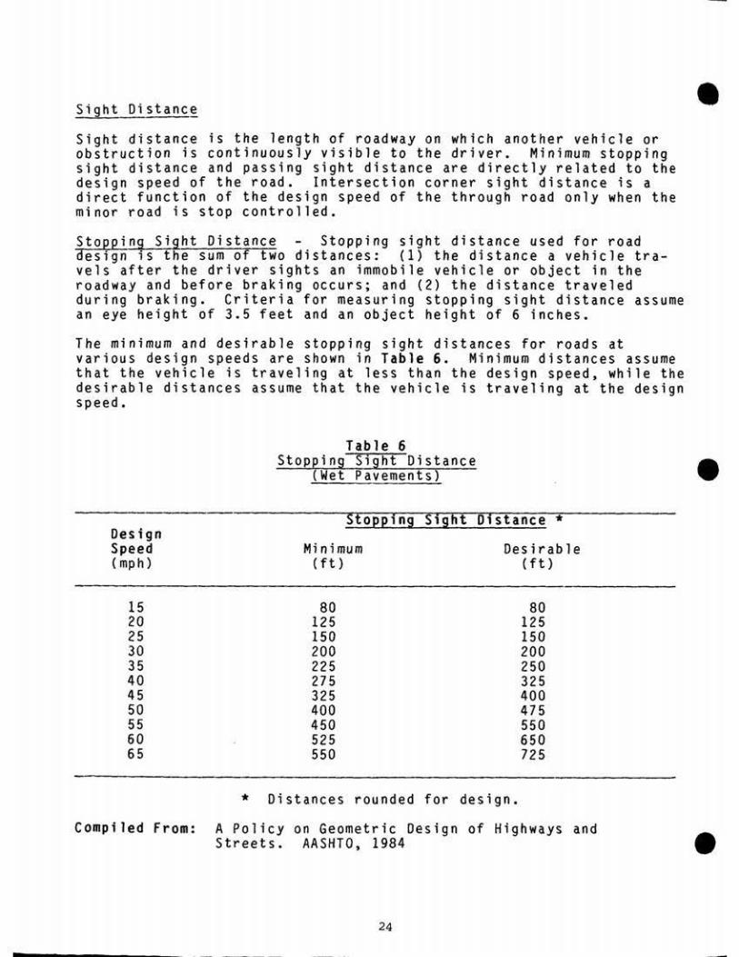
Table 6 Stopping ~ight Distance
(Wet Pavements)
Sight Distance • Sight distance is the length of roadway on which another vehicle or obstruction is continuously visible to the driver. Minimum stopping sight distance and passing sight distance are directly related to the design speed of the road . Intersection corner sight distance is a direct function of the design speed of the through road only when the minor road is stop controlled.
Stoepin~ Sight Distance - Stopping sight distance used for road design ,s the sum of two distances: {l) the distance a vehicle tra-vels after the driver sights an immobile vehicle or object in the roadway and before braking occurs; and (2) the distance traveled during braking. Criteria for measuring stopping sight distance assume an eye height of 3.5 feet and an object height of 6 inches.
The minimum and desirable stopping sight distances for roads at various design speeds are shown in Table 6. Minimum distances assume that the vehicle is traveling at less than the design speed, while the desirable distances assume that the vehicle is traveling at the design speed.
• Stopping Sight Distance*
Design Speed {mph)
Minimum (ft)
Desirable (ft)
15 20 25 30 35 40 45 50 55 60 65
80 125 150 200 225 275 325 400 450 525 550
80 125 150 200 250 325 400 475 550 650 725
* Distances rounded for design.
Compiled From: A Policy on Geometric Design of Highways and Streets. AASHTO, 1984 •
24

• On two-directional, one-lane roads, enough sight distance must be allowed to enable one of two vehicles approaching from opposite direc-tions to reach a turnout or for both to stop before colliding. Criteria for measuring stopping sight distance for one-lane roads assume an eye height of 3.5 feet and an opposing-vehicle height of 4.25 feet. The stopping sight distance for a two-way, one-lane road must be approximately twice the stopping sight distance for a two-lane road. Suggested stopping sight distances and "K" values for one- and t wo-directional, one-lane roads are given in Table 7.
! A "K" value is a coefficient by which the algebraic difference in grade is multiplied to determine the length in feet of the vertical curve which will provide minimum sight distance. The length in feet should not be less than three times the design speed in m.p.h. for any vertical curve.
J Table 7
Stopping Sight Distance One-Lane Roads
• Desi <1" :>oeed { mon J 15 zu z:, .SU 35 40 45 :,u 55
One-Direct iona 1 One-Lane Roads
Stopping Sight -minimum 80 125 150 200 225 275 325 400 450 Distance (ft) -desirable
K Values for:
250 325 400 475 550
Crest Vertical -minimum 5 10 20 30 40 60 80 110 150 Curve -desirable 50 8 120 160 220
Sag Vert ica 1 -minimum 8 20 30 40 50 60 70 90 100 Curve 50 70 90 110 130
Two-Directional One-Lane Roads
StQpping Sight (These design speeds are not recom,ended for two-directional, one-lane roads.)
Distance (ft)
K Values for:
175 250 400
Crest Vertical Curve 10 20 52 Sag Vertical Curve 11 20 40
C0111Piled From: A Pol icy on Geometric Design of Highwa.ys and Streets. AASHTO, 1984
25

Passing Sight Distance Safe passing sight distance applies only to two-lane, two-way roads. Passing sight distance is the length of • highway ahead necessary for one vehicle to pass another before meeting an oncoming vehicle that appears after the passing maneuver has begun. Passing sight distances used for design are given in Table 8. These distances for design should not be confused with the values for no-passing zone pavement markings on complet~d roads shown in the MUTCD. For multi-lane roadways, stopping sight-distance criteria control.
Table 8 Minimum Passing Sight Distance
for Design of Two-Lane Roads
Tab 1 e 9 Sight Distance at Intersections
Design Speed (mph)
Minimum Passi ng Sig ht Distance (ft - rounded)*
15 700 20 800 25 1000 30 1100 35 1300 40 1500 45 1700 50 1800 55 2000 60 2100 65 2300
• * These distances assume that the passed
vehicle is traveling 10mph slower than the passing vehicle.
Compiled From: A Policy on Geomet r ic Design of Highways and Streets. AASHTO, 1984
Minimum passing sight distance should be provided as frequently as possible, particularly on Class I roads that require visitors to travel considerable distances before reaching activity sites.
Intersection Sight Distance Intersections should be planned and located to provide as much sight distance as possible. To achieve a safe design , sufficient sight distance should be provided as a minimum to allow a driver to cross the through road without requiring approach-i~g traffic to reduce ·speed. Minimum intersection sight distances for . different design speeds are shown on Table 9. .·
26
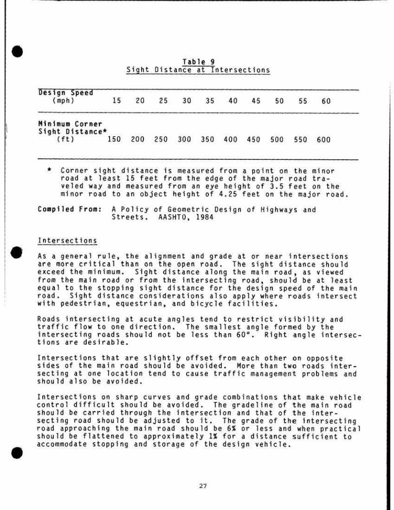
• Design Speed
(mph) 15 20 25 30 35 40 45 50 55 60
Minimum Corner Sight Distance*
(ft) 150 200 250 300 350 400 450 500 550 600
* Corner sight distance is measured from a point on the minor road at least 15 feet from the edge of the major road tra-veled way and measured from an eye height of 3.5 feet on the minor road to an object height of 4.25 feet on the major road.
Compiled From: A Policy of Geometric Des i gn of Highways and Streets . AASHT0, 1984
• Intersections
As a general rule, the alignment and grade at or near intersections are more critical than on the open road. The sight distance should exceed the minimum . Sight distance along the main road, as viewed from the main road or from the intersecting road, should be at least equal to the stopping sight distance for the design speed of the main road . Sight distance considerations also apply where roads intersect with pedestrian, equestrian, and bicycle facilities.
Roads intersecting at acute angles tend to restrict visibility and traffic flow to one direction. The smallest angle formed by the intersecting roads should not be less than 60°. Right angle intersec-tions are desirable.
Intersections that are slightly offset from each other on opposite sides of the main road should be avoided. More than two roads inter-secting at one location tend to cause traffic management problems and should also be avoided.
Intersections on sharp curves and grade combinations that make vehicle control difficult should be avoided. The gradeline of the main road should be carried through the intersection and that of the inter-secting road should be adjusted to it. The grade of the Intersecting r oad approaching the main road should be 6% or less and when practical
• should be flattened to approximately 1% for a distance sufficient to accommodate stopping and storage of the design vehicle .
27

l I I '
It is advisable to provide sufficient width for a vehicle to pass • another vehicle stopped at the intersection. The combination of the width of the main road and the radius of the taper of the intersecting road should provide adequate width for vehicles entering or leaving the main road. For intersections where significant volumes of turning maneuvers occur, consideration should be given to providing turning lanes. Where turning roadways are used, adequate lengths for merge/diverge lanes should be provided.
Number of Lanes
The number of lanes should be sufficient to accommodate the design traffic volume. For low-volume park roads, capacity conditions do not normally govern design, and two travel lanes are appropriate. However, on extremely low volume access roads to remote areas, one-lane two-way roads with frequent turnouts may be considered. Where passing opportunities are significantly limited, auxiliary passing lanes or turnouts should be considered. When the design volume exceeds 8,000, a four-lane divided roadway section may be required to accommodate traffic. For multi-lane roads, the design hourly volume controlling lane capacity is 1,500 vehicles/hour/lane.
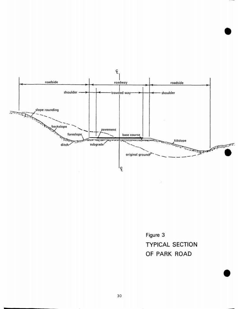
Cross-Section
The roadway cross-section consists of traveled ways, auxiliary lanes , shoulders, medians, and roadsides. Proper roadway width is selected • on the basis of numerous factors including park resource consdera-tions, existing and/or planned volumes and types of traffic, safety, terrain, and design speed. A typical cross-section of park road is illustrated in Figu r e 3.
Traveled Way The traveled way is that portion of the roadway available for movement of vehicles, exclusive of shoulders and auxi-liary lanes. It is usually comprised of two or more traffic lanes.
Shoulders The term shoulder describes that portion of the roadway, contiguous with the traveled way, intended for the accommodation of stopped vehicles, for emergency use, and for lateral support of sub-base, base, and surface courses. The shoulder on park roads with low traffic volumes serves essentially as structural lateral support for the road surfacing and as an additional emergency width for the narrower traveled way. Where there is appreciable traffic volume, roads with narrow surfacing and narrow shoulders often give poor traf-fic service, may have high accident experience, and require frequent and costly maintenance. The low traffic volumes and relatively low operating speeds on most park roads do not warrant wide shoulders.
• 28

Table 10 Minimum Roadwa.l:'. Cross-Section Reguirements
• In addition, wide shoulders may be environmentally and aesthetically objectionable, or may encourage undesirable random stopping or parking. However, as design volumes, design speeds or vehicle sizes increase, additional shoulder width is required for safety and struc -tural support . Shoulders may be dirt, gravel, paved, turf, stablized turf or a combination of surfaces, depending upon land surface type, bi cycle use, climate, maintainability and aesthetic objective.
These fa c ts and concerns are reflected in the lane and shoulder widths shown in Table 10.
'! I
Average Daily Traffic
(ADT)
Number of
Lanes
Lane Width Feet 2_/
Shoulder Width Feet/Si de
La ne Surface Type(s)
<50 50-200
200-400 400-1000
2 2 2 2
8 9 9
10
1 1 2 3
Dirt/Gravel/Paved Dirt/Gravel/Paved Gravel/Paved Paved
1000- 4000 2 11 3 Paved 4000-8000 2 11 4 Paved
>8000 4 12 8 E_/ Paved •
a/ Widening of traffic lanes should be sharp curves. Where tour buses are of recreational vehicles exceeds 5% additional foot of lane width shall exceed 12 feet.
provided on the inside of allowed or the proportion of the design volume, an be considered, not to
b/ Would only apply, as appropriate, to urban parkways.
Where guardrail is used, the graded width of shoulder should be increased to provide about 2 feet outside the guardrail posts to pro-vide lateral support.
The total roadway width (including shoulders) for low volume, one-lane, one-way roads should not exceed 14 feet because of the tendency of drivers to use a wider facility as a two-lane road •
• 29
roadside
slope rounding ).. ...... ·- --.,1 . ,:.., . . ,_/ __ _
'. .... ' .... .... ___
shoulder -
--,. .. ~ backs lope ........, ,
foreslope.
roadside
-t-1--+..t-- shoulder
base course
... ' '-.._--.... _..,\\ ...
-.........._ '''v ' · ~~.n_c=,,,-~ .__ __ _ original ground)'--- -.... _ .- ,..-..-
Iii roadway
--,.+-lf.-.--traveled way•-
. ......., _ pavement
-.............._ , .. . , ,.,
subgrade'
•
. .,-::,.,:-:. ,r., . •
Figure 3
TYPICAL SECTION OF PARK ROAD
30
•

\
• Rccrc atic~ Arc ~s As a r ule, Class I roads in areas used primarily for recreation serve functions broader than other par k roads . Accordingly, where necessary to accommodate recreational vehicles and boat trailer use, traveled-way widths for two-way roads in recreation areas should be 24 feet of pavement (two 12' lanes) plus shoulders of 4 feet . In those recreation areas where the road is part of a thr ough highway, it is not necessary to apply a higher standard within the area than exists for the road way outside the area, provided minimum park road standards have been met.
Bikeways If bicyc l ing is encouraged, consideration must be given to prov i ding safe travel ways. Separate bikeways are normally the safest alter-native and should be considered . Where this is not practica l , and where a wider road section can be accommodated, sho u lder areas may be imp r oved to provide reasonable separation of bicycles from higher-speed traffic. Shoulder areas intended for bicycle use should provide 4 feet of width per direc t ion of travel and should be smooth surfaced, and delineated and marked to indicate the usage. Two-way bicycle traffic on the same shoulder should not be allowed. On low- volume, low-speed roads, the sharing of travel lanes may be considered •
• Surface Type The type of roadway surface to be used is deter mined by the desired visual appe arance, the volume and composition of traffic, environmen-tal considerations, soil condi t ions, avai l ab i lity and cost of materials, and the extent and cost of maintenance. Tab l e 10 shows the suggested surface types for various design volumes. Hi gh volu me traffic justifies high - type pavements with smooth riding qualities and good no n-skid properties in all weather . Most park roads should have a surface whic h will re t ain the cross-sect ion , which will adequately suppo r t the planned volume and weights of vehicles without failure to keep no n-routine maintenance to a minimum, and which will be har-monious with the park environment.
Surface Crown Surface cross-slope must be provided to ensure adequ ate drainage. However, excessive surface sloping can cause steering difficulties. Cross-slope fo r paved su r faces should range from 0.01 to 0 . 03 ft/ft. For uns urfaced dirt or grave l roads , a cross-slope ranging from 0.04 to 0. 06 ft/ft should be provided to allow adequate drainage. On one-lane roads with low- t ype surfaces, a cro wn wou ld not usually be provided. Roads of this type should be slope-graded to provide for
• proper drainage .
31

Roadside Slopes and Drainage • Where terrain conditions and park resources permit, bac kslopes, foreslopes, and roadside drainage channels should have gentle, well-rounded transitions which will be achieved through slope rounding. Generous rounding at the top of backslopes is especially important to minimize erosion and ensure long term stability and revegetation of cut slopes. Each end of a cut- or fill-slope should be warped to provide a pleasing appearance. Flatter foreslopes are generally more stable and facilitate revegetation. The maximum rate of foreslope depends on terrain conditions and the stability of soils as determined by local experience. In desert country where fill-s lopes do not vege-tate readily, embankments or slopes should be overlaid or "painted" with rock or soil of matching color. ·
The ditch foreslope used in design should be related to design speed, type of terrain, soil types, and resource management considerations. Preferably the ditch foreslope should be 6:1 for urban parkways and 4:1 for Class I Park Roads . The firs t 10 feet of the fill slope should also be 4:1 where practicable to provide emergency pull off, yet discourage random parking.
Cut sections should be designed to provide for adequate ditches or other drainage features to ensure positive drainage. The ditch must be large enough to accommodate the design flows and deep enough to provide for satisfactory drainage of the pavement base. In appro-priate cases, underdrains should be used to lessen impacts. In the case of rock cuts, drill holes or tool marks should not be visible • from the roadway.
Drainage structures, channels , and ditches must be hydraulically designed based on sound principles of hydrology and based on the required considerations of the . effect on floodplains.
Guardrail/Guiderail
Guardrails or guardwalls are barriers intended to redirect an errant vehicle , thus preventing it from hitting a roadside or median hazard. Guiderails, guidewal l s or guide posts are intended only to delineate the road way , or to warn of roadside hazards.
Guardrail or guardwalls should be installed at points of unusual danger such as sharp curves and steep embankments, particularly at those points that are unusual compared with the overa l l characteristics of the road. The criteria used for warranting guardrail installation on high-speed, high-volume highways do not apply to the low- speed, low-volume traffic conditions on most park roads.
• 32

- ln add1tion. placement and design of both guardrail and guiderail should be as consistent as possible for both safety and appearance throughout the length of a particular roadway . Choice of materials and design should be sensitive to the setting or environment. In snow country, design and location should recognize snow-removal methods.
Curbs
Except where necessary to control traffic or drainage or to provide for road widening, the use of barrier curbs on roadways should be avoided for safety, economy and simplic1ty. Where barrier curbs are continuous along a low speed highway, they should be offset at least l foot and preferably at least 2 feet from the edge of traffic lane and so carried across all structures . Barrier curbs introduced on bridges or intermittently elsewhere should be offset at least 2 feet and preferably 3 feet .
33

RESURFACING, RESTORATION & REHABILITATION PROJECTS • The primary purpose of the 3-R work ttie National Park Service will undertake is to preserve and extend the service life of park roads and to enhance their safety (23 U.S.C. 109(0)). Park roads on which geometrics were established several decades ago are capable in most instances of providing safe, useful service. In such cases, minor improvements will make those roads serviceable for many more years, and the complete reconstruction which would be required on such roads to meet current standards would be prohibitively costly and environ-mentally objectionable.
A primary consideration in the development of 3-R projects is applica-tion of criteria which will allow the necessary flexibility to adjust to actual field conditions. · Consequently, the geometric information that follows is generally the minimum considered acceptable. On 3-R work, the intent should be to improve above these minimums, where feasible, and to ensure the highest level of safety possible within existing conditions and constraints.
Guidance for 3-R projects can be found in FHWA's Direct Federal Manual , 3(C)(l), Appendix l, "Direct Federal Geometric Design Criteria for Non-Freeway 3-R Projects" .
Traffic Volume 3-R projects are undertaken primarily to meet • specific current needs. Where significant levels of rehabilitation are involved, a desirable design volume should be established through management decisions based on a 5- or 10-year traffic forecast.
Design Speed Roads scheduled for 3-R work should be eval-uated based on the desirable design speed which would accomodate the current running speed, but a minimum design speed should not be established. lt is essential, when considering a project for a section of park road, that the geometric conditions beyond the portion to be improved also be evaluated and cons i dered to obtain uniformity and to achieve consistency in design over the entire route. Every attempt should be made to maintain a _uniformly safe running speed for a significant segment of the roadway. Consideration should be given to providing a transition between portions of a roadway having different design speeds.
Pavement and Shoulder Widths The criteria for roadway cross-sections established for new construction and reconstruction apply to 3-R projects, where feasible.
• 34

• Grades, Curvature Sight Distance & These geometric features would usually require an older road to be reconstructed, if current stand-ards were to be achieved, and could not normally be achieved with 3-R work. The level of reconstruction necessary to satisfy these cri-teria might also cause impacts on surrounding areas which the Service would deem inappropriate .
During the project planning phase, however, all hazardous locations along a roadway should be identified and accident records should be analyzed to determine if roadway features are contributing to acci-dents. If accidents relate to grade, cross-section, curvature or ' sight distance, consideration should be given to reconstruction improvements at critical locations (and/or to control of veh icular types and speeds, improved signing, etc.)
Generally, however, the previously existing geometric features (such as grade, curvature and sight distance) wi ll be retained on 3-R projects. In such cases, each vertical and horizontal curve should be checked for stopping sight distance to determine if it is less than that required for safety at the posted speed. If so, advisory limited sight distance signs giving the appropriate speed should be installed. In some instances, where encroachment of vegetation has impaired original sight distance, appropriate pruning or removal shall be
• accomplished •
Bridges Approaches for narrow bridges (including one-way bridges) should be signed and delineated in accordance with MUTCD.
Historic Structures A number of park roads and parkways, or struc-tures on them (e.g. bridges, walls and overlooks) are historic in themselves, and are in some instances listed on the National Register. Preservation or restoration may be the only option for such historic roadways or structures .
• 35

STRUCTURES, SIGNING & MAINTENANCE • Structures
The engineering design of bridges, culverts, walls, tunnels, and ancillary structures should be in accordance with AASHTO Standard Specifications for Highway Bridges . The design process should be multi-disciplinary to address aesthetic, historical, and environmental considerations.
The minimum design loading for new roadway bridges should be H-15. Higher design loadings may be appropriate, depending on use. The vertical clearance at underpasses should be at least 14 feet above the entire roadway width. The clear roadway widths for new and reconstructed bridges should desirably be a minimum of the traveled way plus shoulders plus four feet (2 feet on each side).
Bridge railings for Class II through V roads should be designed for low volumes and speeds and to permit lateral scenic viewing, if appropriate. Bridge railings should be located coincident with barrier curbs except where sidewalks are provided.
Signing and Marking
Although safety and efficiency of operation depend to a major extent • on the geometric design of a road, they should be supplemented by standard signing and marking to provide appropriate traffic control and safety and to provide information to drivers. The Manual on Uniform Traffic Control Devices (MUTCD), as supplemented by the National Park Service Sign Manual, contains details regarding design, location, and application of road signs and markings as they apply to park roads and parkways. Application of standard signing and pavement markings shall be incorporated as part of the design process. During construction, project traffic control shall be provided by the contractor, including erection and maintenance of all necessary barricades; suitable and sufficient lights, as appropriate; and danger signals, signs and other traffic control devices in conformity with a project traffic control plan and with Part VI of the MUTCD.
Ma intenance
Road design is but one component in the overall management of road facilities, and must be considered in this light as part of a continuing program of road and bridge facilities management and oper-ations. This process of road management commences with advance planning and extends all the way through mainte nance and operation. •
36

- To assure a continuously acce ptable level -0f safe traffic service for park visitors , it is essential to desig n park roads appropriately to allow for maintenance and periodic resurfacing , restoration and reha-bilitation (3-R work) throughout the life of the road .
Road safety and efficiency of operation depend on adequate levels of cyclic and preventat1ve maintenance and repair, which are also essen-tial to protect the Service's extensive capital investment in the physical facility constituted by park roads, parkways and bridges . Consequently, park roads shal l be maintained to the standards to whic h they have been constructed or reconstructed, and in a condition that promotes safety and protects capital investment .
* * *
37

GLOSSARY OF SELECTED TERMS
• AASHTO Abbreviation for American Association of State Highway and Transportation Officials.
ADT cf. "Average Daily Traffic".
Aesthetics A branch of philosophy dealing with beauty and the beautiful and judgments of taste concerning them. In highway engineering, aesthetic judgments have to do primarily with the appearance of the highway or road as •a whole, including the road-side and its relationship to the natural and cultural environment through which it passes.
Average Dai ly Traffic {ADT) The average 24-hour volume, being the total volume during a stated period divided by the number of days in that period, normally a year or the number of days the road is actually open to public travel.
Average Running Speed For all traffic, or a component thereof, the summation of distances traveled divided by the summation of running times.
• Backslope In cuts, the slope from the bottom of the ditch to the
top of the cut.
Bridge A structure exceeding 20 feet clear span measured along the centerline of the roadway, which carries traffic over a watercourse or opening.
Broken Back Curve An arrangement of curves in which a short tangent separates two curves in the same direction.
Capacity - The maximum number of vehicles which has a reasonable expectation of passing over a given section of lane or roadway during a given time period under prevailing roadway and traffic conditions.
Centerline (1) For a two-lane road, the centerline is the middle of the traveled way; and for a divided road, the centerline may be the center of the median. For a divided road with independent roadways, each roadway has its own centerline. (2) The defined and surveyed line shown on the plans from which road construction is controlled.
Critical Length of Grade That combination of gradient and length of grade which will cause a designated vehicle to operate at some predetermined minimum speed. A lower speed than this is unacceptable and usually requires that an auxiliary climbing lane be provided for slow-moving vehicles •
• 39

Cross Section The transverse profile of a road showing horizontal • and vertical dimensions.
Cross Walk Any portion of a roadway at an intersection or elsewhere distinctly delineated for pedestrian crossing by signs and by lines or other mar kings on the surface.
Culvert Any structure under the roadway with a clear opening of 20 feet or less measured along the center of the roadway.
Curve Widening The widening of the traveled way on sharp curves to compensate for the fact that the rear wheels of a vehicle do not follow exactly in the track of the front whee ls .
Curvilinear Alignment A flow ing alignment in wh ich the majority of its length is composed of circular and spiral curves.
Cut Section That part of the roadway which, when constructed, is lower in elevation tha n the original ground.
Design Speed A speed selected for purposes of design and corre-l ation of the physical features of a road that influence vehicle operation . It is the maximum safe speed that can be maintained over a specified section of the road when conditions are so favorable that the design features of the road govern. •
Design Vehicle A selected motor vehicle, the weight, dimensions, and operating characteristics of which are used as a control in road design.
Design Vehicle Turning Radi~s The turning radius of a Design Vehicle, used primarily to determine the mini mum radius used in the design of turn i ng and intersecting roadways.
Design Volume A volume determined for use in design, representing the traffic expected to _use the road.
Embankment A raised earth structure on which the roadway pavement structure is placed.
Fill Section cf. "Embankment•.
Foreslope The slope from the edge of the surfaced shoulder to the top of the subgrade, or the bottom of the ditch in cuts.
functional Classification The grouping of individual roads in a road system according to their purpose or function and the type of traffic or use they serve.
• 40

• Geometric Besign The arrangement of the visible elements of a road, such as alignment, grades, sight distances, widths, slopes, etc.
Grade (1) The profile of the center of the roadway , or its rate of ascent or descent. (2) To shape or r eshape an earth road by means of cutting or filling. (3) Elevation.
Grade Separation A structure which provides for traffic to pass over or under another road or railroad.
Horizontal geometrics of the roadway.
Horizontal Curve A curve or transitional by means of which a road can chan
Horizontal Alfgn ■ent
ge direction to the right or left.
Hourly Volume The number of vehicles passing over a given section of la ne or roadway during one hour.
Intersection The general area where two or more roads join or cross, within wh ich are included the roadway and roadside facilities for traffic movements in that area.
Intersection Angle The angle between two intersecting roads.
• • Lanes Auxiliary Lane - The portion of the roadway adjoining the traveled way for parking, speed change, turning, storage for turning, weaving, truck climbing, or for other purposes supplementary to through traffic movement.
Med i an Lane - A speed-change lane within the median to accom-modate left -turning vehicles.
Parking Lane - An auxiliary lane primarily for the parking of vehicles.
Speed-Change Lane - An auxiliary lane, including tapered areas, primarily for the acceleration or deceleration of veh icles entering or leaving the through traffic lanes.
Turn Lane - A traffic lane with in the normal surfaced width of a roadway, or an auxiliary lane adjacent to or within a median, reserved for vehicles turning left or right at an intersection.
Traffic Lane - The portion of the traveled way for the move-ment of a single line of vehicles in one direction .
• 41

-------------
Level of Service A qualitative rating of the effectiveness of a • .. road relative to the service it reroers to its user s , measured
in terms of a number of factors, such as operating speed, travel time, traffic interruptions, freedom to manuever and pass, driving safety, comfort, and convenience .
Med ian The portion of a divided roadway separating the traveled ways for traffic in opposite directions .
Merg i ng - The converging of separate streams of traffic into a single stream.
Multi-Lane Road A road having two or more lanes for traffic in each direction, or four or more lanes for traffic in t wo direc-tions. It may be one-way or two-way , divided or undivided.
Overloo k (Sceni c Over look ) A roadside area provided for motorists to stop their vehicles beyond the traveled-way, primarily for viewing scenery in safety.
Passing Opportunity - A section of two-lane , t w.o-directional road where sufficient clear sight distance exists to allow a safe passing maneuver to be performed.
Passing Sight Distance The minimum sight distance that must be available to enable the driver of a vehicle to pass another •· safely and comfortably without interfeting with the speed of an oncoming vehicle traveling at the design speed should it come into view after the overtaking maneuver is started.
Pavement Markings Devices or paint placed on the roadway to mark pavement for vehicular and pedestrian traffic control.
Paveme nt St ructure The combination of subbase, base course, and su r face course placed on a subgrade to support the traffic load and distribute it to the roadbed.
Base Course - The layer or layers of specified or selected material of designed thickness placed on a subbase or a subgrade to support a surface course.
Subbase - The layer or layers of specified or selected material or designed thickness placed on a subgrade to support a base course .
Subgrade - T~e top surface of a roadbed upon which the pavement structure and shoulders, including curbs, are constructed.
• 42

1
• Subgrade Treatment - Modification of roadbed materia l by stabili-zation.
Surface Course - One or more layers of a pavement st r ucture designed to accommodate the traffic load, the top layer of which resists skidding, traffic abrasion, and t he disintegrating effects of climate . The top layer is sometimes called •wearing Course" .
Pedestrian Crossing (Cross walk) An area clearly marked for the passage of pedestrians at street junctions or other locations where drivers must yield the right-of-way by stopping to enable pedestrians to cross safely.
Profile A longitudinal section of a roadway, drainage course, etc.
\
Recreation Vehicle (RV) - A vehicle specifically designed for recreational use, usually considerably larger than a passenger car and frequently containing kitchen, sleeping and toilet facilities.
Resurfacing The placing of one or more new courses on an existing road surface.
Reverse Curve • A curve consisting of two arcs of the same or different radii curving in opposite directions and having a common tangent or transition curve at their point of junction.
Road (Highway) A general term denoting a public way for purposes of vehicular travel, including the entire area within the right-of-way.
Roadside A general term denoting the area adjoining the outer edge of the roadway. Extensive areas between the roadways of a divided road may also be considered roadside.
Roadway - The portion of a highway, including shoulders, for vehicular use. A divided highway has two or more roadways.
Running Speed cf. "Average Running Speed".
Service Vo l ume The maximum number of vehicles that can pass over a given section of a lane or roadway in one direction on a multi - lane road or in both directions on a t wo-lane road during a specified time period, which is stated as an hourly volume and which varies according to the level of service •
• 43

Shoulder The portion of the roadway contiguous with the traveled • way for accommodation of stopped vehicles , for emergency use, and for lateral support of base and surface courses.
Sight Distance The length of roadway ahead vis ible to a driver.
Skid Resistance The frictional force between a locked tire and a pavement, wh ich force resists motion.
Slope The face of an embankment or cut section; any ground the surface of which makes an angle with the plane of the horizon.
Speed The rate of movemen t of a vehicle, generally expressed in miles per hour (mph).
Spiral Curve cf. "Transition Curve".
Standard Criteria having recognized and usually permanent values which are established formally as a model or requirement.
Stopping Sight Distance - The distance required by a driver of a vehicle, traveling at a given speed, to bring his vehicle to a stop after an object on the roadway becomes visible, including the distance traveled . during the perception and reaction times, as well as the vehicle braking distance.
Superelevatton The elevating of the outside edge of a curve to • partially offset the centrifugal force generated when a vehicle rounds the curve.
Supere levatto n Runoff The transition distance between normal crown and fully superelevated roadway .
Sustained Grade A continuous road grade of appreciable length and consistent, or near l y consistent, gradient.
Traffic All types of vehicles, together wit h their loads, either singly or as a whole, including pedestrians, while using a roadway for the purpose of transportation.
Traffic Control Device A sign, signal, marking or other device placed on or adjacent to a street or h1ghway by authority of a public body or official having jurisdiction to regulate, warn, o.r guide traffic.
Traffic Control Signal - Any device--whether manually, electri-cally, or mechanically operated--by which traffic i s alternately directed to stop and permitted to proceed.
• 44

• Traffic Markings - All lines, patterns, words, colors, or other devices--except signs - -set into the surface of, applied upon, or attached to the pavement or curbing or to objects within or adjacent to the roadway, officially placed for the purpose of regulating, warning, or guiding traffic.
Traffic Sign - A device mounted on a fixed or portable support whereby a specific message is conveyed by means of words or symbols, officially erected for the purpose of regulating, warning, or guiding traffic . \
Traffic Signal - A power - operated traffic control device by which traffic is regulated, warned, or alternately directed to take specific actions.
Traffic Volume The number of vehicles passing a given point during a specified period of time.
Transition A section of variable pavement width required when changing from one width of traveled way to a greater or lesser width.
Transition Curve (Spiral) A curve of variable radius intended to effect a smooth transition from tangent to curved alignment.
Traveled Way -• The portion of the roadway for the movement of vehicles, exclusive of shoulders and auxiliary lanes.
Turn Angle cf. "Angle of Turn•~
Turning Path The path of a designated point on a vehicle making a spec i fied turn. (cf. al~o "Minimum Turning Path")
Turning Track Width The radial distance between the turning paths of the outside of the outer front tire and the outside of the rear tire which is nearest the center of the turn.
Vertical Align•ent (Profile &ride) ~ The trace of a vertical plane intersecting ·the top surface of the proposed wearing surface, usually along the longitudinal ~enterline of the roadbed, being either elevation or gradient of such trace according to the context.
Vertical Curve A curve on the longitudinal profile of a road providing a change of gradient.
Wearing · Cou r se (S urface Course ) The top layer of a pavement.
•
• * * *
45

Sketch by Benjamin C. Howland Dec.
Awarded USDI Distinguished Service Award Fellow American Society of Landscape Architects Retired from N .P .S. 1975
•