Parametric studies of a shipboard impressed current ... · Parametric studies of a shipboard...
12
Parametric studies of a shipboard impressed current cathodic protection system using a boundary element code Y. wang', D. P. ~rennan~ & M. chernuka2 i Defence R&D Canada - Atlantic, Halifax, Nova Scotia, Canada 2 Martec Limited, Halifax, Nova Scotia, Canada Abstract The performance of a shipboard impressed current cathodic protection (ICCP) system, operating under various conditions, was evaluated using a computer model. A Canadian naval vessel ICCP system was chosen as a prototype for this study. A variety of factors were taken into account in this study, including the locations of reference electrodes, paint damage and paint degradation, conductivity of seawater, and polarization curve data of the propeller and ship hull materials. A boundary element code developed at DRDC Atlantic was used for the analysis. The studies performed provide an increased understanding of the performance of the shipboard ICCP system under various conditions. 1 Introduction Coatings and impressed current cathodic protection (ICCP) are established tools for use in the protection of ship platforms from corrosion. Coatings provide primary corrosion protection for a ship by isolating the hull metal from the seawater. ICCP provides secondary corrosion protection in those areas where the paint is breached or degraded. ICCP is an electrochemical technique that uses a DC feedback system to supply current to the unprotected surface of the ship structure in order to maintain the electric potential of the structure at a pre- determined level. The design of an optimized shipboard ICCP system requires accurate placement of the anodes and reference electrodes on a ship hull form. Many shipboard ICCP systems currently in use were designed using empirical Transactions on Modelling and Simulation vol 34, © 2003 WIT Press, www.witpress.com, ISSN 1743-355X
Transcript of Parametric studies of a shipboard impressed current ... · Parametric studies of a shipboard...

Parametric studies of a shipboard impressed current cathodic protection system using a boundary element code
Y. wang', D. P. ~ r e n n a n ~ & M. chernuka2 i Defence R&D Canada - Atlantic, Halifax, Nova Scotia, Canada 2 Martec Limited, Halifax, Nova Scotia, Canada
Abstract
The performance of a shipboard impressed current cathodic protection (ICCP) system, operating under various conditions, was evaluated using a computer model. A Canadian naval vessel ICCP system was chosen as a prototype for this study. A variety of factors were taken into account in this study, including the locations of reference electrodes, paint damage and paint degradation, conductivity of seawater, and polarization curve data of the propeller and ship hull materials. A boundary element code developed at DRDC Atlantic was used for the analysis. The studies performed provide an increased understanding of the performance of the shipboard ICCP system under various conditions.
1 Introduction
Coatings and impressed current cathodic protection (ICCP) are established tools for use in the protection of ship platforms from corrosion. Coatings provide primary corrosion protection for a ship by isolating the hull metal from the seawater. ICCP provides secondary corrosion protection in those areas where the paint is breached or degraded. ICCP is an electrochemical technique that uses a DC feedback system to supply current to the unprotected surface of the ship structure in order to maintain the electric potential of the structure at a pre- determined level.
The design of an optimized shipboard ICCP system requires accurate placement of the anodes and reference electrodes on a ship hull form. Many shipboard ICCP systems currently in use were designed using empirical
Transactions on Modelling and Simulation vol 34, © 2003 WIT Press, www.witpress.com, ISSN 1743-355X

relationships and engineering judgment. Today, computer-modelling techniques have become an acceptable practice in many corrosion-related studies in order to supplement experimental work. Munn [ l ] summarized the early computer modelling development of galvanic corrosion and cathodic protection up to mid- 1980. Zamani et a1 [2] also surveyed different computational techniques used for modelling galvanic corrosion and cathodic protection. In the past 15 years, the use of the boundary element method (BEM) in both galvanic corrosion and cathodic protection studies has become commonplace [3 - 61.
The objective of this paper is to evaluate a shipboard ICCP system performance. The factors studied include paint damage and paint degradation due to age effect, seawater conductivity, material polarization resistance response, and location of reference electrode. A boundary element code, called CPBEM (cathodic Erotection Boundary Element Modelling), developed at Defence R&D Canada - Atlantic was used in the study.
2 Theoretical Basics for the Modelling
In a galvanic corrosion or cathodic protection problem, the governing equation for the electrostatic potential reflecting the flow of electric current in a homogeneous electrolyte from anodic to cathodic sites is the Laplace equation:
where 4 is electric potential referred to a known reference electrode. The current density vector is proportional to the gradient of the electric potential 4. Therefore
where o is the conductivity of associated electrolyte. Since this paper deals with a shipboard ICCP problem in an open sea, the computational domain includes the infinite fluid domain exterior to the hull and the propeller. The structureiseawater interface consists of three areas: anode (sacrificial anode or inert anode), cathode (e.g. propeller, paint damage, and paint degradation), and insulation (i.e. well-painted area). The boundary conditions for these three areas are as follows:
I ) Anode
2) Cathode 84 - = fc (4 ) an
3) Insulation
where n is the unit outward normal to the surface. For an ICCP system, the normal derivative of 4 (i.e. current density) on each anode is a specified
Transactions on Modelling and Simulation vol 34, © 2003 WIT Press, www.witpress.com, ISSN 1743-355X

Boundary Elrmcnt Tcrhnology XV 183
constant. On the cathodic areas (which include surfaces where bare metal is exposed) the current density is normally a nonlinear function of the electric potential. This current densitytpotential relationship, commonly referred to as the polarization curve, can only be obtained experimentally.
Three numerical techniques have been used for the solution of Laplace's equation: the finite difference method (FDM), the finite element method (FEM), and the BEM [2]. In cases involving exterior models, both the FDM and FEM require discretization of a large volume of the electrolyte surrounding the structure, resulting in a very large number of equations. However, the BEM requires discretization of the structure surface only, which greatly reduces the size of the numerical model. As a result, the BEM has become the favored method used in the modelling of ICCP systems.
3 Boundary Element Code
The CPBEM code consists of a model generator, a solver, and a post-processor, which are integrated into a Windows interface. The solver was based on a boundary element program originally developed by Zamani and coworkers under contract to DRDC Atlantic [3, 71. The solver includes two algorithms to deal with both linear and non-linear polarization data [S]. The solver is capable of modelling multiple cathodic and anodic areas with different polarization curves. In addition, the solver is capable of computing the electric potentials and electrostatic fields at user-specified locations in the electrolyte. The constant element algorithm was implemented in the solver.
Model generation and meshing of a 3-D structure, such as a ship hull, is known to be a time-consuming task. The difficulty lies in the meshing over the irregular surface of a ship hull. To overcome this difficulty, the CPBEM model generator was specially designed to automatically generate and mesh a shipboard model. The user needs to describe only the boundaries of the region to be meshed. The model generator automatically creates an optirnized mesh based on the user-defined element sizes. The anodic areas, cathodic areas, and insulation, as well as their corresponding properties (e.g. input current, polarization curve data) can be defined interactively. In addition, the model generator can also automatically generate field points at user-defined locations in electrolyte where the electric field values are desired.
The CPBEM post-processor displays both potential and current density profiles within its Windows interface. In addition, the post-processor also generates a TecplotTM [9] interface to allow users to review the modelling results using Tecplot's advanced post-processing capabilities. The modelling results presented in this paper were plotted using Tecplot.
The code has been verified using various 2-D and 3-D models [g]. The computer modelling results using the CPBEM code were also compared to physical scale modelling results of electric potential profiles along a shipboard model and good agreement was obtained [10].
Transactions on Modelling and Simulation vol 34, © 2003 WIT Press, www.witpress.com, ISSN 1743-355X

4 Ship Model and Material Definitions
The model under consideration is based on the two-zone ICCP system used on board a Canadian naval ship. The model, generated using the CPBEM code, is presented in Figure 1. Because of the symmetry to the central plane, only half the ship hull form needs to be modelled. The model included the locations of the propeller, anodes, and reference electrodes. The propeller, which is made of nickel-aluminum-bronze (NAB), was modeled as a disk that was electrically connected to the ship hull form. The rudder, shaft, A-brackets, and bilge keel were not included in the model. Note that the zone-one ICCP system alternatively uses the reference electrode at stem (reference electrode lb) and the one fore of the zone-one anode (reference electrode la) as its controlling reference electrode. This provides the basis of investigations on the effect of the location of the reference electrode.
Zone 2 rcfcrcncc
electrode (Ib)
Figure 1: Model for the two-zone ICCP system.
The model also included paint damage to approximately 10% of the wet surface area. The large light area illustrated in Figure 1 represents the well- painted area or degraded paint, depending on the boundary conditions assigned in the area. A total of 1350 elements were used in the model, with smaller elements assigned to the area adjacent to the anodes. This mesh design will facilitate the smooth variation of the potential profiles expected in this area. The degree of mesh refinement used in this study was based on the results obtained in a series of parametric studies performed in a previous investigation [10].
The polarization curve data needs to be provided for each type of cathodic area (propeller, paint damage area, and degraded paint) as boundary conditions. In an ICCP system, the structure to be protected is polarized to and maintained at a certain potential level for an extended period of time. Therefore, long-term polarization curve data obtained using the potentiostatic technique should be used as input to the numerical model. The most comprehensive collection of polarization curve data related to naval materials submerged in seawater was compiled by Hack [l l]. In this study, Hack's long-term polarization curve data for NAB and steel under quiescent condition were used. For paint damage areas,
Transactions on Modelling and Simulation vol 34, © 2003 WIT Press, www.witpress.com, ISSN 1743-355X

Boundary Elrmcnt Tcrhnology XV 185
the polarization current was assumed to be 20% of the polarization current for the bare steel. The dynamic condition was modeled by tripling the polarization current for the NAB propeller and the paint damage areas.
Paint degradation is defined as the decrease in coating resistance as a result of the permeation of water, 02, and other ions into the coating. Since the coating resistance is significantly higher than the metallelectrolyte interface resistance, a linear polarization curve was assumed as the boundary condition for the degraded paint with the slope equal to the polarization resistance of the coating. As a result, the potentiallcurrent relationship may be expressed as
where E, is the corrosion potential of the steel (assumed to be -650 mV vs. AgIAgCI in seawater). The literature data showed that for a 183 pm thick coating the coating resistance, R,, varied from a value greater than 10' C2.cm2 at start of exposure to a value close to 105 !2-cm2 after a 200-day exposure in artificial ocean water [12]. Three coating resistances, lo9, 106, and 10' i2.cm2, were used for modelling different stages of paint degradation.
In order to provide the necessary level of protection for ship structures submerged in seawater, ICCP systems should be capable of maintaining surface potentials of approximately -850 mV vs. AgIAgCl electrode. The ideal potential range on the hull form is between -800 nlV to -900 mV. In the computer modelling performed during this study, an assumed value for the anode current was used as an initial first guess. The computed potential at the location of the reference electrode was compared with a pre-set value (i.e. -850 mV), and then the current was adjusted. The iteration process continued until the potential at the location of the reference electrode was equal to -850 +_ 1 mV. The computation for each case took about 15 to 25 minutes on a PC of 700 MHz processor and 256 MB RAM. Most of this time was consumed assembling and decomposing the associated system of equations, with only a small fraction required for the iteration process.
5 Results
In the modelling work performed in this study, unless specified, only zone one ICCP system was activated, and the potential at reference electrode l a (see Figure 1) was the feedback potential. The potential profiles along the longitudinal axis of the ship hull that were presented in this paper were obtained along a vertical plane that was parallel to and 1 m from the central plane.
The conductivity of seawater varies with seawater chlorinity and temperature. Reference [l31 provides the surface seawater conductivity data at various chlorinity and temperatures. The ocean temperature could be as low as 0°C in Canadian coastal waters in winter, and as high as 25°C in the Arabian Sea in summer. The conductivity is lower in colder seawater and in brackish water. For example, the conductivity at 25°C with chlorinity about 18 mg1L is about 0.05
Transactions on Modelling and Simulation vol 34, © 2003 WIT Press, www.witpress.com, ISSN 1743-355X
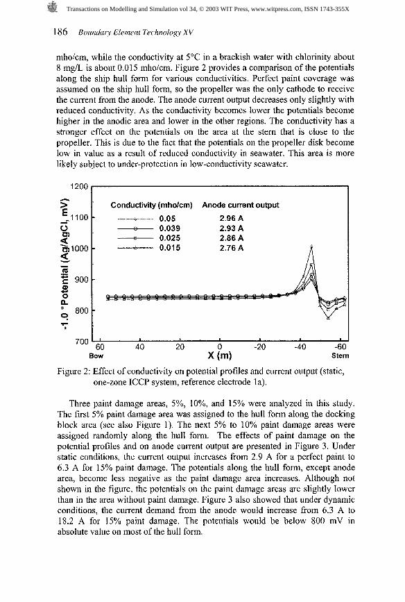
mholcm, while the conductivity at 5'C in a brackish water with chlorinity about 8 mg/L is about 0.01 5 mholcm. Figure 2 provides a comparison of the potentials along the ship hull form for various conductivities. Perfect paint coverage was assumed on the ship hull form, so the propeller was the only cathode to receive the current from the anode. The anode current output decreases only slightly with reduced conductivity. As the conductivity becomes lower the potentials become higher in the anodic area and lower in the other regions. The conductivity has a stronger effect on the potentials on the area at the stern that is close to the propeller. This is due to the fact that the potentials on the propeller disk become low in value as a result of reduced conductivity in seawater. This area is more likely subject to under-protection in low-conductivity seawater.
? Conductivity (mholcm) Anode current output ell^^ - --a 0.05 2.96 A - - 0.039 2.93 A
a --a 0.025 2.86 A 31000 - ---A 0.015 2.76 A 4 - m .." E 900 - a, U 0
800 - 9
Figure 2: Effect of conductivity on potential profiles and current output (static, one-zone ICCP system, reference electrode la).
Three paint damage areas, 5%, 10%, and 15% were analyzed in this study. The first 5% paint damage area was assigned to the hull form along the docking block area (see also Figure 1). The next 5% to 10% paint damage areas were assigned randomly along the hull form. The effects of paint damage on the potential profiles and on anode current output are presented in Figure 3. Under static conditions, the current output increases from 2.9 A for a perfect paint to 6.3 A for 15% paint damage. The potentials along the hull form, except anode area, become less negative as the paint damage area increases. Although not shown in the figure, the potentials on the paint damage areas are slightly lower than in the area without paint damage. Figure 3 also showed that under dynamic conditions, the current demand from the anode would increase from 6.3 A to 18.2 A for 15% paint damage. The potentials would be below 800 mV in absolute value on most of the hull form.
Transactions on Modelling and Simulation vol 34, © 2003 WIT Press, www.witpress.com, ISSN 1743-355X

Boundary Elrmcnt Tcrhnology XV 187
. Paint damage area and anode current output n - 0% 2.9 A - - 5 % 4.1 A - 10% 5.2 A - 15% 6.3 A - 15% (dynamic) 18.2 A
sow l
Stern
Figure 3: Effect of paint damage on potential profiles and current output (static unless specified, one-zone ICCP system, reference electrode la).
Polarization resistance of paint Anode current output - Rp=109 (perfect paint) 2.9 A - Rp=106 4.8 A - R ~ = I O ~ 19.3 A - -0- - RP-10' (dynamic) 24.2 A
I h Figure 4: Effect of paint degradation on potential profiles and current output
(static unless specified, one-zone ICCP system, reference electrode la).
The effect of the overall paint degradation on the cathodic protection performance is presented in Figure 4. This figure shows that the current demand from the anode only increases from 2.9 A to 4.8 A when the coating resistance decreases from lo9 !2+cm2 to 10' 0cm2. But the demand increases to 19.3 A if
Transactions on Modelling and Simulation vol 34, © 2003 WIT Press, www.witpress.com, ISSN 1743-355X
the coating resistance decreases to 105 i2,cm2. Also, the potentials on the hull form do not change much when the coating resistance decreases from lo9 to 106 Ckcm2. The potentials shift about 50 mV to less negative values on the most hull form when the coating resistance decreases from 106 0 c m 2 to 105 0 c m 2 . These results imply that the paint degradation would not affect the ICCP performance until the coating resistance decreases to about 106 C&cm2. Figure 4 also shows the effect of flow on the potentials and the current output. Note that the coating resistance was not affected by flow and, therefore, only the boundary condition for the propeller was changed. It is seen that under dynamic conditions, the most notable change in the potential profile was that the potentials on the area close to the propellershifted about 50 &V to less negative values.
Anode current output
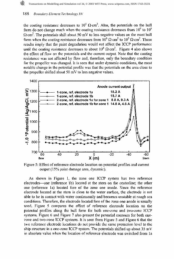
'- l -%one, ref. electrode l a - - l -zone, ref. electrode l b -- 2-zone, ref. electrode l a for zone 1 8.8 A, 9.3 A - 2-zone, ref. electrode l b for zone 1 14.0 A, 4.6 A
*
- 'i'
700 I 6'0 I I I I I I
40 20 0 -20 -40 -60 BOW X (m) Stem
Figure 5: Effect of reference electrode location on potential profiles and current output (15% paint damage area, dynamic).
As shown in Figure 1, the zone one ICCP system has two reference electrodes-one (reference lb) located at the stern on the centerline; the other one (reference la) located fore of the zone one anode. Since the reference electrode located at the stem is close to the water surface, the electrode is not able to be in contact with water continuously and becomes unstable at rough sea conditions. Therefore, the electrode located fore of the zone one anode is usually used. Figure 5 compares the effect of reference electrode location on the potential profiles along the hull form for both one-zone and two-zone ICCP systems. Figure 6 and Figure 7 also present the potential contours for both one- zone and two-zone ICCP systems. It is seen from Figure 5 and Figure 6 that the two reference electrode locations do not provide the same protection level to the ship structure in a one-zone ICCP system. The potentials shifted up about 35 mV in absolute value when the location of reference electrode was switched from l a
Transactions on Modelling and Simulation vol 34, © 2003 WIT Press, www.witpress.com, ISSN 1743-355X

Boundary Elrmcnt Tcrhnology XV 189
to lb. This shift in potentials was accompanied by a slight increase in current demand (from 18.2 A to 18.7 A). It is clearly seen that use of reference electrode lb would provide better cathodic protection to the ship structure than use of reference electrode la. In the two-zone ICCP system, as shown in Figure 5 and Figure 7, changing the location of reference electrode does not affect significantly the potentials on the forward part of the ship. On the hull form aft of the propeller, the potentials were raised about 30 to 40 mV when the location of the reference electrode was switched from l a to lb.
Comparison of Figure 6 and Figure 7 also shows that the two-zone ICCP system provides a better cathodic protection level than the one-zone ICCP system. In addition, the two-zone ICCP system requires slightly less anode current than the one-zone system does.
The results obtained indicate that positioning a reference electrode is important in providing suEcient cathodic protection to the ship hull. The reference electrode, or one of the reference electrodes in a multi-zone ICCP system, should be placed near the region that is least protected. For the naval ship, this region is in the vicinity of the propeller. If an alternative reference electrode location has to be used, the pre-set controlling potential level should be adjusted accordingly to reflect the hull potential variation as a result of the change in reference electrode location. For example, a pre-set controlling potential of -885 mV at reference electrode l a would provide about the same cathodic protection level to a pre-set controlling potential of -850 mV at reference electrode lb. Computer modelling is a useful tool for evaluating the effect of the location of reference electrode on the ICCP performance.
Side view -1'Potential (mV)
a) Reference electrode l a
Side view
Bottom vlew 800 790 U L . , ~ ~ ~ ~ R ~ ~ ~ ~ ~ & - ~ ~ ~ \ ~ ~ / ~ 780
, /- ($3 F ~ O , p-2, . +&q43 %+-'9, 1 . M& 770 760
b) Reference electrode l b 750
Figure 6: Contour plots showing effect of reference electrode location on potential profiles (15% paint damage, dynamic, one-zone ICCP system).
Transactions on Modelling and Simulation vol 34, © 2003 WIT Press, www.witpress.com, ISSN 1743-355X

Side view -1 'Potential (mV)
Bottom vlew
, S? .%G&? /d b) Reference electrode I b
Figure 7: Contour plots showing effect of reference electrode location on potential profiles (15% paint damage, dynamic, two-zone ICCP system).
6 Summary
The computer modelling for evaluating the performance of a shipboard ICCP system has been demonstrated using a boundary element code developed at DRDC Atlantic. The code includes a model generator that is specially designed for generating models for a shipboard ICCP system or sacrificial anode cathodic protection system.
The parameters studied that affect a shipboard ICCP performance include seawater conductivity, paint damage and paint degradation, location of reference electrode, and the polarization curve data of ship structure materials. The modelling results have shown that the variation of the conductivity of seawater does not significantly affect the current demand of the ICCP system. Under- protection may be a concern on some area of the ship platform if the ship enters a low-conductivity water zone.
The modelling results also showed that paint damage results in increased current demand and reduced cathodic protection level, especially under dynamic conditions. The effect of paint degradation on the ICCP performance was found to be insignificant until the coating resistance decreases to a certain level. The computer modeling also demonstrated that the two-zone ICCP system provides better cathodic protection to the ship hull form than the one-zone ICCP system.
The importance of positioning the reference electrode has been demonstrated. The level of cathodic protection has been found to vary with the location of the reference electrode. The normal practice is to maintain the potential level at the location of reference electrode at -850 mV (vs. AgIAgC1 electrode). This practice is based on the assumption that the reference electrode is located at an optimized location. If an alternative reference electrode location has to be used,
Transactions on Modelling and Simulation vol 34, © 2003 WIT Press, www.witpress.com, ISSN 1743-355X

Boundary Elrmcnt Tcrhnology XV 19 1
the controlling potential level at this location should be adjusted in order to preserve the cathodic protection level.
References
[ l ] R.S. Munn, A review of the development of computational corrosion analysis for special corrosion modelling through its maturity in the mid-1980's. Computer Modelling in Corrosion, ASTM STP 1 154, ed. R.S. Munn, ASTM, pp. 21 5-228, 1992.
[2] N.G. Zamani, J.F. Porter and A.A. Mufti. A survey of computational efforts in the field of corrosion engineering. Int. J. Numer. Methods in Engng., 23, pp. 1295-131 1, 1986.
[3] N.G. Zamani, Boundary element simulation of the cathodic protection system in a prototype ship. Applied Mathematics And Computation, 26, pp. 119-134, 1988.
[4] V.G. DeGiorgi, E.D. Thomas, A.I. Kaznoff, Numerical simulation of impressed current cathodic protection (ICCP) systems using boundary element methods. Computer Modelling in Corrosion, ASTM STP 1154, ed. R.S. Munn. ASTM, pp. 265-276, 1992.
[S] R.A. Adey and S.M. Niku, Computer modelling of corrosion using the boundary element method. Computer Modelling in Corrosion, ASTM STP 1 154, ed. R.S. Munn, ASTM, pp. 248-263, 1992.
[6] V.G. DeGiorgi, A review of computational analyses of ship cathodic protection systems, Boundary Elements XIX, Computational Mechanics Publications: Southhampton, pp. 829-838, 1997.
[7] N.G. Zamani, Computer aided design in cathodic protection systems. DRDC Atlantic contractor report, DREA CR18614 19, 1986.
[8] K.J. KarisAllen, C.A. Tawel, K.D. MacKay, and D. Brennen, Impressed current cathodic protection (ICCP) physical scale modelling (PSM) and CPBEM modelling of Canadian Patrol Frigate (CPF) hull potential profiles, DRDC Atlantic contractor report, DREA Cl21200 1/0 14,2001.
[9] Tecplot 9.0 User's Manual, Amtec Engineering, Inc. Bellevue, Washington, 2001.
[l01 Y. Wang, J.F. Porter, K.J. KarisAllen, D.P. Brennan, J. Wallace, and M. Chernuka, "Development of the DRDC Atlantic program for modelling impressed current cathodic protection", Proceedings of 11'~ Inter-Naval Corrosion Conference, Auckland, New Zealand, 2002.
[ l l ] H.P. Hack, Atlas of Polarization Diagrams for Naval Materials in Seawater, CARDIVNS WC-TR-6 1-94/44, Survivability, Structures and Materials Directorate Technical Report, Naval Suface Warfare Centre, USA, 1995.
[l21 J. R. Scully, Electrochemical impedance of organic-coated steel: correlation of impedance parameters with long-term coating deterioration, J. Electrochem. Soc, 136(4), pp. 979-990, 1989.
[13] R. Baboian, NACE Corrosion Engineer's Reference Book, 3rd Ed. NACE Press, p. 148,2002.
Transactions on Modelling and Simulation vol 34, © 2003 WIT Press, www.witpress.com, ISSN 1743-355X

Transactions on Modelling and Simulation vol 34, © 2003 WIT Press, www.witpress.com, ISSN 1743-355X