Parametric model for generation and analysis of modular ...
16
_________________________ D. Veenendaal, Summum Engineering, Van Vollenhovenstraat 14, 3016 BH Rotterdam e-mail: [email protected] M. Bovio, LeadingEDGE Marine Engineering, Bernardus Gewinstraat 14C, 3031 SE, Rotterdam e-mail: [email protected] O. Sainz Avila and G. Visch, Boskalis Research and Development, Rosmolenweg 20, 3356 LK Papendrecht, Netherlands e-mail: [email protected] and [email protected] Parametric model for generation and analysis of modular, freeform floating island networks, constructed using flexibly formed Buoycrete ® . Diederik Veenendaal, Marco Bovio, Oscar Sainz Avila and Guido Visch Abstract A robust parametric model is presented that can generate different polygonal regular tilings or irregular networks of freeform, modular floating islands. The doubly curved geometry is possible by using Buoycrete, a neutrally buoyant, non-dissolvable concrete mix. This allows for floating bodies that are designed and optimized beyond what is traditionally possible with conventional construction. One output from the parametric model, a single module designed for North Sea conditions, is evaluated using diffraction and CFD analysis to inform the parametric model and to demonstrate the potential of our approach. Keywords Parametric modelling · Flexible formwork · Buoycrete · CFD · Floating island 1 Introduction The world’s growing population, coupled with sea level rise due to climate change, has generated interest in land creation at sea. Modular floating islands can potentially create such space in an affordable and sustainable manner. Other driving forces are the need for industrial space, logistical purposes, leisure or creating space in international waters with its own jurisdiction. The concept of large floating cities captured our imagination throughout history, and past decades have seen many proposals [1,2], including, but not limited to those from: Paul Maymont (1926- 2007); Koen Olthuis, Docklands/Waterstudio; ATDesignoffice; Blue21/DeltaSync; Vincent Callebaut; Oceanix; the Seasteading Institute; and the Venus Project, Jacque Fresco (1916-2017). Their concepts consist of either single or multiple modular floating bodies, many circular or hexagonal in shape. An ongoing study, Space@Sea, concluded that while “a triangle shape [..] shows the highest flexibility”, “the use of deck
Transcript of Parametric model for generation and analysis of modular ...

_________________________
D. Veenendaal, Summum Engineering, Van Vollenhovenstraat 14, 3016 BH Rotterdam
e-mail: [email protected]
M. Bovio, LeadingEDGE Marine Engineering, Bernardus Gewinstraat 14C, 3031 SE, Rotterdam
e-mail: [email protected]
O. Sainz Avila and G. Visch, Boskalis Research and Development, Rosmolenweg 20, 3356 LK
Papendrecht, Netherlands
e-mail: [email protected] and [email protected]
Parametric model for generation and analysis of
modular, freeform floating island networks,
constructed using flexibly formed Buoycrete®.
Diederik Veenendaal, Marco Bovio, Oscar Sainz Avila and Guido Visch
Abstract A robust parametric model is presented that can generate different
polygonal regular tilings or irregular networks of freeform, modular floating
islands. The doubly curved geometry is possible by using Buoycrete, a neutrally
buoyant, non-dissolvable concrete mix. This allows for floating bodies that are
designed and optimized beyond what is traditionally possible with conventional
construction. One output from the parametric model, a single module designed for
North Sea conditions, is evaluated using diffraction and CFD analysis to inform the
parametric model and to demonstrate the potential of our approach.
Keywords Parametric modelling · Flexible formwork · Buoycrete · CFD ·
Floating island
1 Introduction
The world’s growing population, coupled with sea level rise due to climate change,
has generated interest in land creation at sea. Modular floating islands can
potentially create such space in an affordable and sustainable manner. Other driving
forces are the need for industrial space, logistical purposes, leisure or creating space
in international waters with its own jurisdiction. The concept of large floating cities
captured our imagination throughout history, and past decades have seen many
proposals [1,2], including, but not limited to those from: Paul Maymont (1926-
2007); Koen Olthuis, Docklands/Waterstudio; ATDesignoffice; Blue21/DeltaSync;
Vincent Callebaut; Oceanix; the Seasteading Institute; and the Venus Project,
Jacque Fresco (1916-2017).
Their concepts consist of either single or multiple modular floating bodies,
many circular or hexagonal in shape. An ongoing study, Space@Sea, concluded
that while “a triangle shape [..] shows the highest flexibility”, “the use of deck
2
space for a square floater is more efficient.” (Fig. 1) [3]. Recent concepts feature
more irregular networks of triangles, squares and pentagons (Fig. 2).
Fig. 1 Triangular and square floating bodies: Space@Sea study by Blue21/DeltaSync with
Waterstudio, ICE Marine Design Group, 2019
Fig. 2 Floating City Project with squares and pentagons, 2013 by the Seasteading Institute with
Blue21/DeltaSync, and BlueRevolution with triangles, 2015 by Blue21/DeltaSync
2 Parametric model
A robust parametric CAD model is presented that can generate different patterns of
multiple islands; both regular tilings and irregular tessellations. The model is set up
in Grasshopper/Rhinoceros3D.
Each island (Fig. 3) has a polygonally shaped perimeter and deck area, so that it
can be connected to its neighbors to form a network. An opening in the middle can
be used for fish farms, optional quay walls for small ships, and to allow for more
daylight entry to the seabed.
Each floater has a freeform toroidal body to form a sort of semi-submersible
shaped island. Semi-submersibles are commonly used in the offshore industry and
are characterized by lower wave loads and motions compared to full body floating
objects because of their reduced form stability. The body is made using Buoycrete:
a neutrally buoyant, non-dissolvable concrete mix.
Initially, a low-polygonal mesh is created, which is later refined through
Catmull-Clark subdivision [4]. This allows for rapid generation and iteration of the
model. The upper deck is determined by: the number of sides; the number of
columns per side; the deck clearance; and, the inner and outer radius. The radius of
the lower torus is governed by the column positions on the upper deck and the

3
perimeter of the deck. The columns themselves can vary in radius, as can the cross
section of the torus. The deck has ribs designed to follow lines of principal stresses
[5]. The lines of the quadrilateral mesh are then used to construct surfaces, so the
geometry is represented both as a mesh and as a polysurface (Fig. 3).
Fig. 3 Low-poly mesh, mesh from Catmull-Clark subdivision with internal deck structure, and
reconstructed polysurface of the outer body
For multiple adjacent floating bodies, a tiling of regular convex polygons [6] or
tessellation of irregular polygons can be used as the basis for their arrangement. The
simplest regular tilings are triangular, square and hexagonal, and infinite
combinations are possible by including dodecagons. The parametric model is set up
for any tiling or tessellation to be used (Fig. 4).
Fig. 4 An Archimedean tiling consisting of squares, hexagons and dodecagons, and an irregular
Voronoi tessellation, consisting of unique convex polygons, both generated from the same model.
4
3 Buoycrete
The complex, freeform geometry of each module is made possible by using
Buoycrete, a neutrally buoyant, non-dissolvable concrete mix, with a patented work
technology and method [7]. There are no comparable lightweight cement mixtures
available on the market.
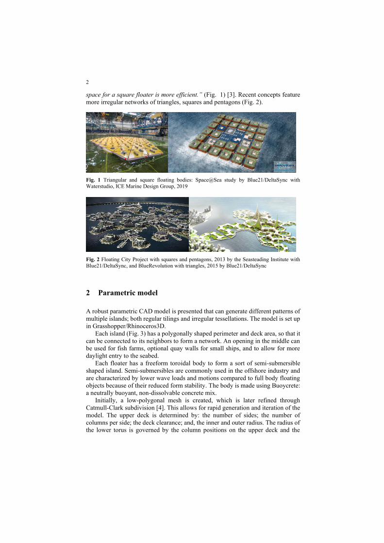
The high slurry pressures that arise when pouring regular concrete in a hard
formwork are not apparent with Buoycrete underwater. Thus, inflatable and other
flexible formworks made of inexpensive fabrics like geotextiles or plastic foils can
be used to form predefined (complex) concrete shapes. When a complete formwork
is inflated (filled with Buoycrete), the predefined shape becomes instantly apparent.
Figure 5 shows the result of a first inflatable demonstration in the Boskalis
laboratory, using a low-cost plastic formwork. After curing under water, the
structure was removed from the basin and loads could be applied on top. To
manufacture such a structure with regular concrete, above water, an expensive,
milled or printed, rigid formwork would be needed to withstand the slurry pressures
and avoid collapse of the formwork.
Fig. 5 Buoycrete demonstrator and 7-days UCS load test with 100kg static load.
The mixture research is under constant development and with a tunable aggregate
weight and percentage, the density and compressive strength can be tuned to a
desired level. Table 1 shows properties for a density equal to that of water. A side-
effect of our lightweight aggregate is the low modulus of elasticity.
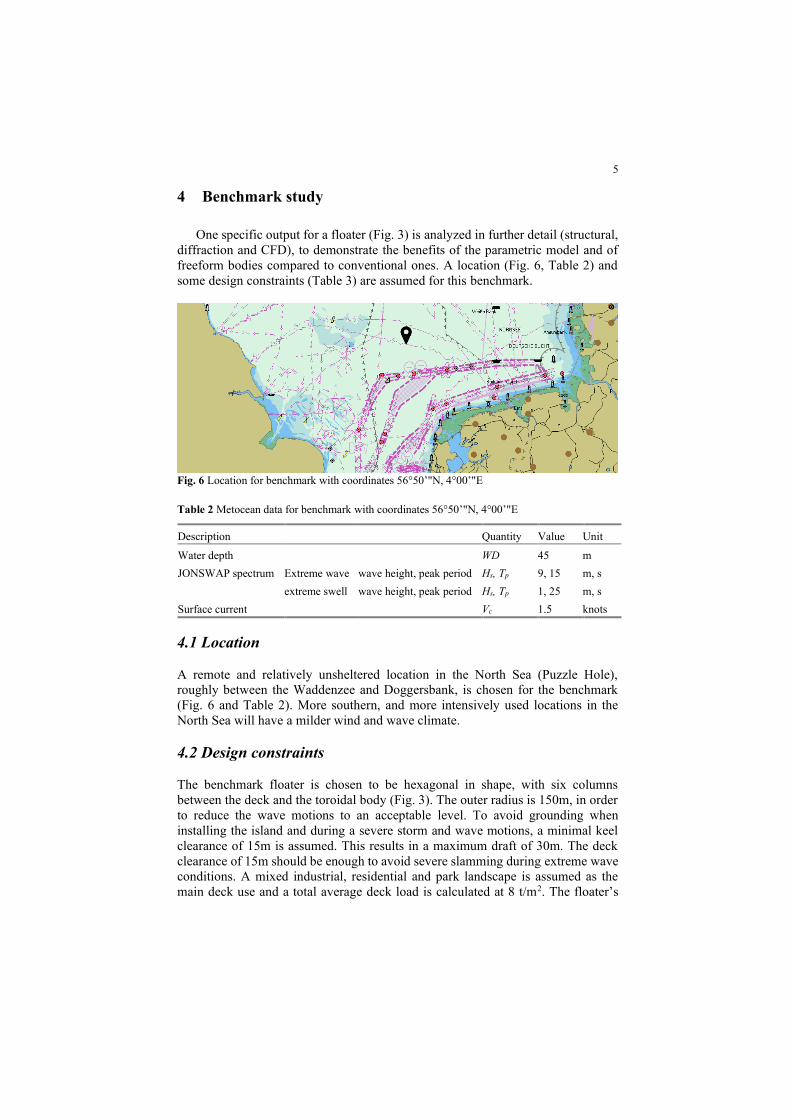
Table 1 Buoycrete properties for density equal to that of water
Property Value Unit
Uniaxial compressive strength UCS 35-40 MPa
Indirect tensile strength ITS >2 MPa
Young’s modulus E 5-6 GPa
Density ρ 1’000 kg/m3
5
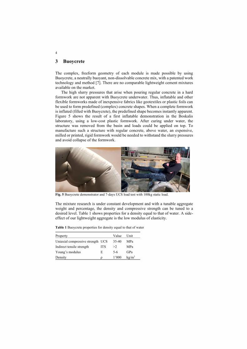
4 Benchmark study
One specific output for a floater (Fig. 3) is analyzed in further detail (structural,
diffraction and CFD), to demonstrate the benefits of the parametric model and of
freeform bodies compared to conventional ones. A location (Fig. 6, Table 2) and
some design constraints (Table 3) are assumed for this benchmark.
Fig. 6 Location for benchmark with coordinates 56°50’"N, 4°00’"E
Table 2 Metocean data for benchmark with coordinates 56°50’"N, 4°00’"E
Description Quantity Value Unit
Water depth WD 45 m
JONSWAP spectrum Extreme wave wave height, peak period Hs, Tp 9, 15 m, s
extreme swell wave height, peak period Hs, Tp 1, 25 m, s
Surface current Vc 1.5 knots
4.1 Location
A remote and relatively unsheltered location in the North Sea (Puzzle Hole),
roughly between the Waddenzee and Doggersbank, is chosen for the benchmark
(Fig. 6 and Table 2). More southern, and more intensively used locations in the
North Sea will have a milder wind and wave climate.
4.2 Design constraints
The benchmark floater is chosen to be hexagonal in shape, with six columns
between the deck and the toroidal body (Fig. 3). The outer radius is 150m, in order
to reduce the wave motions to an acceptable level. To avoid grounding when
installing the island and during a severe storm and wave motions, a minimal keel
clearance of 15m is assumed. This results in a maximum draft of 30m. The deck
clearance of 15m should be enough to avoid severe slamming during extreme wave
conditions. A mixed industrial, residential and park landscape is assumed as the
main deck use and a total average deck load is calculated at 8 t/m2. The floater’s
6
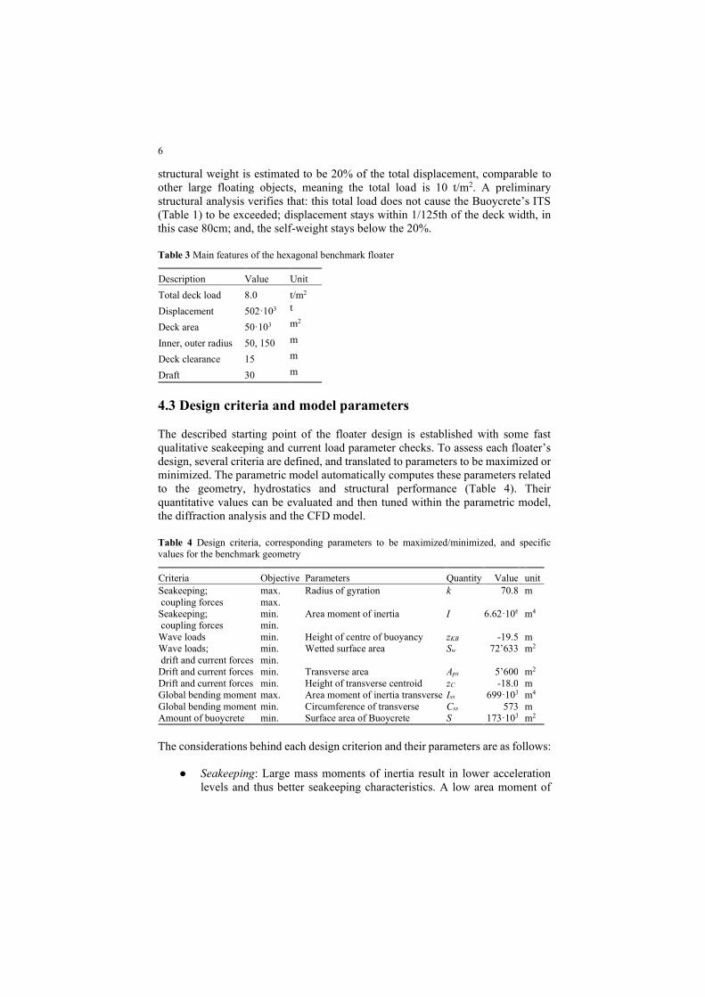
structural weight is estimated to be 20% of the total displacement, comparable to
other large floating objects, meaning the total load is 10 t/m2. A preliminary
structural analysis verifies that: this total load does not cause the Buoycrete’s ITS
(Table 1) to be exceeded; displacement stays within 1/125th of the deck width, in
this case 80cm; and, the self-weight stays below the 20%.
Table 3 Main features of the hexagonal benchmark floater
Description Value Unit
Total deck load 8.0 t/m2
Displacement 502·103 t
Deck area 50·103 m2
Inner, outer radius 50, 150 m
Deck clearance 15 m
Draft 30 m
4.3 Design criteria and model parameters
The described starting point of the floater design is established with some fast
qualitative seakeeping and current load parameter checks. To assess each floater’s
design, several criteria are defined, and translated to parameters to be maximized or
minimized. The parametric model automatically computes these parameters related
to the geometry, hydrostatics and structural performance (Table 4). Their
quantitative values can be evaluated and then tuned within the parametric model,
the diffraction analysis and the CFD model.
Table 4 Design criteria, corresponding parameters to be maximized/minimized, and specific
values for the benchmark geometry
Criteria Objective Parameters Quantity Value unit
Seakeeping;
coupling forces
max.
max.
Radius of gyration k 70.8 m
Seakeeping;
coupling forces
min.
min.
Area moment of inertia I 6.62·106 m4
Wave loads min. Height of centre of buoyancy zKB -19.5 m
Wave loads;
drift and current forces
min.
min.
Wetted surface area Sw 72’633 m2
Drift and current forces min. Transverse area Apx 5’600 m2
Drift and current forces min. Height of transverse centroid zC -18.0 m
Global bending moment max. Area moment of inertia transverse Iss 699·103 m4
Global bending moment min. Circumference of transverse Css 573 m
Amount of buoycrete min. Surface area of Buoycrete S 173·103 m2
The considerations behind each design criterion and their parameters are as follows:
● Seakeeping: Large mass moments of inertia result in lower acceleration
levels and thus better seakeeping characteristics. A low area moment of

7
inertia, or reduced stability, also reduces the acceleration levels and
comfort on board of floating bodies.
● Load transfer (coupling forces): With a low stability, the wave induced
pitching moment will be smaller. Thereby, a small pitch mass moment of
inertia will reduce the needed coupling forces to counteract the rotational
acceleration levels.
● Wave loads: The wave motions and pressures reduce with greater distance
from the waterplane, therefore a low centre of buoyancy generally results
in lower wave loads. In our case, with a relatively low water depth, we
expect the wetted surface area to have a negative influence on the wave
loads because in high seas the wave velocities are far from zero around the
keel line.
● Drift forces and current forces: Analogous to the wave particle velocities,
the current velocity will also reduce at a greater distance from the
waterplane. Therefore, the projected transverse area and distance from the
waterline are of influence on the drift and current forces.
● Global bending moment: Bending moment stresses are calculated with the
cross sectional area moment of inertia of the structure. A large distance
between the deck and torus, and a large diameter of the torus itself will
increase the global stiffness and reduce the global material stresses.
● Amount of Buoycrete: Assuming an overdimensioned wall thickness of the
structure’s surface area because of impact force integrity, water intrusion
and so on, a low surface area will result in less used Buoycrete material.
Large surface curvatures, especially around the columns, will lead to
smaller deformations and material fatigue during the intensive, cyclic
wave loads.
5 Diffraction analysis
For the hydromechanical analysis, a single module generated by the parametric
model (Fig. 3), is studied in more detail as a first iteration. A lower centre of
buoyancy, a small waterline area together with an optimized underwater volume
results in reduced wave motion response and coupling forces between the island
modules. As a comparison, a cylindrical floating island is modeled with an equal
displacement, diameter, centre of gravity above waterline and radius of gyration.
Figure 7 shows the AQWA models and Table 5 the hydrostatic properties of the
freeform floating island (FFI) module and the cylindrical island (CI) floater.
Fig. 7 Freeform floating island and cylindrical floater
8
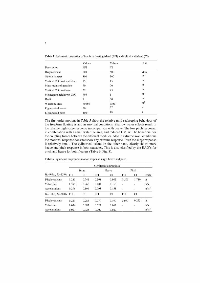
Table 5 Hydrostatic properties of freeform floating island (FFI) and cylindrical island (CI)
Description
Values
FFI
Values
CI
Unit
Displacement 500 500 kton
Outer diameter 300 300 m
Vertical CoG wrt waterline 15 15 m
Mass radius of gyration 70 70 m
Vertical CoG wrt base 22 45 m
Metacentre height wrt CoG 795 1 m
Draft 7 30 m
Waterline area 70686 3555 m2
Eigenperiod heave 50 22 s
Eigenperiod pitch 400+ 16 s
The first order motions in Table 5 show the relative mild seakeeping behaviour of
the freeform floating island in survival conditions. Shallow water effects result in
the relative high surge response in comparison with heave. The low pitch response,
in combination with a small waterline area, and reduced GM, will be beneficial for
the coupling forces between the different modules. Also in extreme swell conditions
the motions’ response does not show any extreme response. Even the surge response
is relatively small. The cylindrical island on the other hand, clearly shows more
heave and pitch response in both seastates. This is also clarified by the RAO’s for
pitch and heave for both floaters (Table 6, Fig. 8).
Table 6 Significant amplitudes motion response surge, heave and pitch
Hs=9.0m, Tp=15.0s
Significant amplitudes
Surge Heave Pitch
FFI CI FFI CI FFI CI Units
Displacements 1.281 0.741 0.368 0.903 0.501 1.710 m
Velocities 0.599 0.266 0.184 0.358 - - m/s
Accelerations 0.296 0.106 0.098 0.158 - - m/ s2
Hs=1.0m, Tp=20.0s FFI CI FFI CI FFI CI
Displacements 0.241 0.283 0.070 0.197 0.077 0.253 m
Velocities 0.074 0.083 0.022 0.061 - - m/s
Accelerations 0.027 0.025 0.009 0.020 - - m/ s2

9
Fig. 8 RAO’s heave and pitch, for freeform floating island (FFI) and cylindrical island (CI)
5.1 Wave elevation and drift forces
There are significant amplitudes of the wave pattern during survival conditions (Fig.
9). Around the columns near the leeward side of the module, some peaks in wave
elevation are found around 9.5m. With a deck height of 15m above waterline and a
very mild heave response, the chances for severe deck slamming are minimal.
Furthermore, the amount of wave obstruction is small (Fig. 9), which means that
wave drift forces are expected to be small, contrary to the wave pattern around the
floating cylinder.
Fig. 9 Significant wave elevation

10
The wave drift forces show remarkable peaks and troughs between 0.3 and 0.9
radians per second. Hypothetically, the discontinuous transverse cross-section of
the floating body in wave direction, with especially the large hole in the middle,
could result in some standing wave phenomena and/or levelling out of wave forces
at certain wavelengths. These mechanisms should lead to lower drift forces
compared to solid box-shaped floating bodies, like the cylindrical floater.
Fig. 10 Wave drift forces per unit wave height
In general, the relatively mild seakeeping behaviour, small waterline area, minimal
wave obstruction and acceptable drift forces show the hydromechanical feasibility
of the designed freeform floating island. Furthermore, the comparison with the
cylindrical floater validates the presumed outcome of the optimization parameters
as described in Section 4, nevertheless this is a first iteration of the complete
analysis of the model. The expected relative low coupling forces could further be
analysed in detail in a coupled multi-body diffraction calculation model.
6 CFD analysis
The parametric model is coupled with a RANSE CFD solver in order to evaluate
the hydrodynamic forces acting on the single floating element due to typical current
streams occurring around the North Sea coastal areas. The CFD analysis was carried
out using FINE™/Marine 8.1, consisting of: NUMECA HEXPRESS™ for
automated all-hexahedral unstructured discretization of the flow domain; ISIS-CFD
for flow computation; and, NUMECA CFView™ for visualization of the results.
During the simulation, only the pitching and heaving motions were solved, to allow
11
for the floater moving to its dynamic equilibrium position. The effects of turbulence
were modelled with the k-ω SST model.
6.1 Computational Mesh
Two computational domains were used for this case study: one for a deep-water
case and a second one for a shallow water environment, which should be more
representative of a coastal installation of the floater. Particular attention has been
dedicated to the latter scenario since the flow entrained in between the floater
structure and the seabed was expected to generate strong interaction forces due to
typical shallow water effects (i.e. blockage). This peculiar situation is generally
resulting in an increment of those forces exerted by the flow on the structure – as
well as on its hydrodynamic equilibrium – due to its local acceleration, hence on
the required tension to be sustained by the mooring lines. To resolve all the relevant
flow features, the domain volume was divided into small cells to generate the
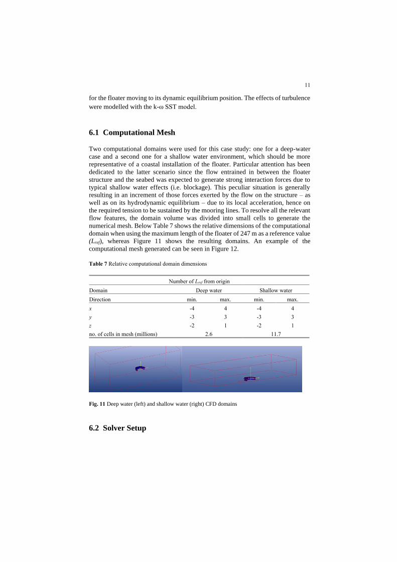
numerical mesh. Below Table 7 shows the relative dimensions of the computational
domain when using the maximum length of the floater of 247 m as a reference value
(Lref), whereas Figure 11 shows the resulting domains. An example of the
computational mesh generated can be seen in Figure 12.
Table 7 Relative computational domain dimensions
Number of Lref from origin
Domain Deep water Shallow water
Direction min. max. min. max.
x -4 4 -4 4
y -3 3 -3 3
z -2 1 -2 1
no. of cells in mesh (millions) 2.6 11.7
Fig. 11 Deep water (left) and shallow water (right) CFD domains
6.2 Solver Setup

12
For a smoother convergence, the simulations were initialised with a zero flow speed
and slowly accelerated to an imposed current speed of 1.5 knots (0.772 m/s) as this
was deemed being representative of the tidal currents encountered in the installation
area of interest. A “Volume of Fluid” (VoF) method was used to account for the
free surface (i.e. both water and air flow are solved), for which the parameters are
given in the table below in accordance with the most recent ITTC recommended
values.
Table 8 Fluid properties
Property Temperature Density Dynamic viscosity
Unit ˚C kg/m3 10-6 Pa·s
Water 19 1’025.07 1’103
Air 19 1.20 18.5
The solver adopts the (Unsteady) Reynolds Averaged Navier Stokes (U)RANS
equations to describe the flow motions and characteristics. These equations need a
closure model for which the two-equations k-ω SST Menter turbulence model was
used. The free stream turbulence quantities were initialized using the reference
length and velocity of the floater as imposed. The wall functions were used to
simulate the flow in regions close to solid walls, reducing the mesh density
requirements in the boundary layer.
Fig. 12 Details of the computational meshes
13
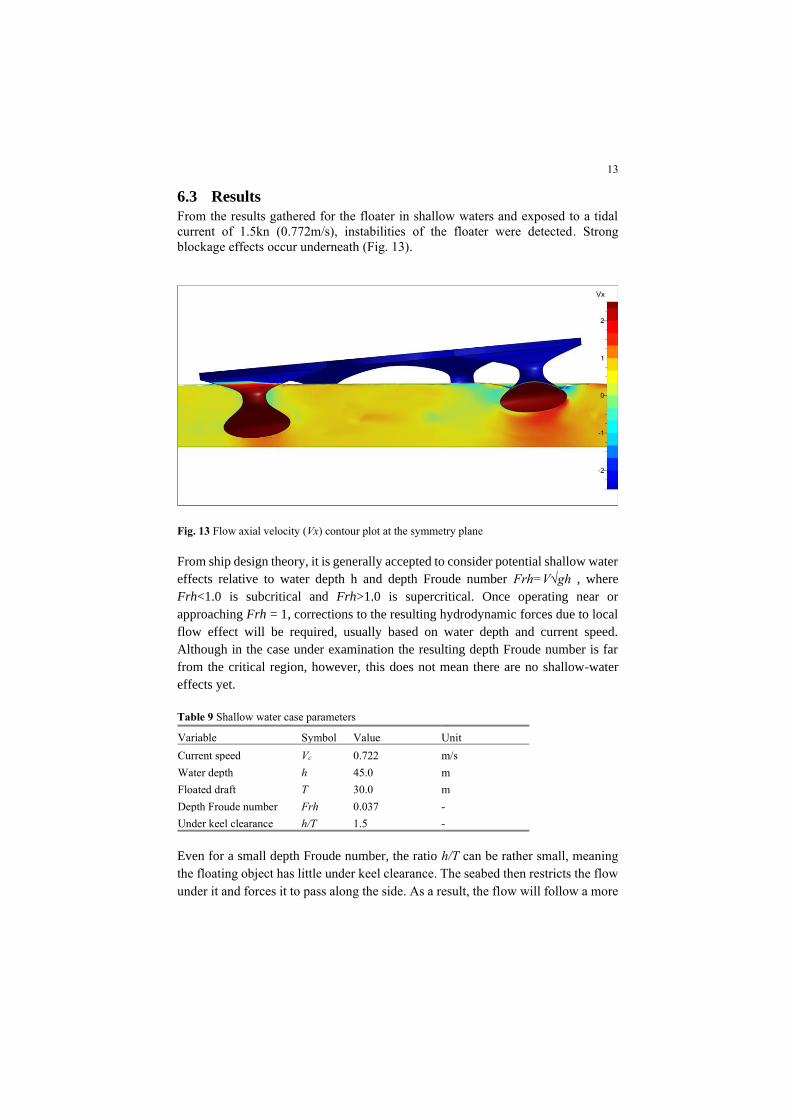
6.3 Results
From the results gathered for the floater in shallow waters and exposed to a tidal
current of 1.5kn (0.772m/s), instabilities of the floater were detected. Strong
blockage effects occur underneath (Fig. 13).
Fig. 13 Flow axial velocity (Vx) contour plot at the symmetry plane
From ship design theory, it is generally accepted to consider potential shallow water
effects relative to water depth h and depth Froude number Frh=V√gh , where
Frh<1.0 is subcritical and Frh>1.0 is supercritical. Once operating near or
approaching Frh = 1, corrections to the resulting hydrodynamic forces due to local
flow effect will be required, usually based on water depth and current speed.
Although in the case under examination the resulting depth Froude number is far
from the critical region, however, this does not mean there are no shallow-water
effects yet.
Table 9 Shallow water case parameters
Variable Symbol Value Unit
Current speed Vc 0.722 m/s
Water depth h 45.0 m
Floated draft T 30.0 m
Depth Froude number Frh 0.037 -
Under keel clearance h/T 1.5 -
Even for a small depth Froude number, the ratio h/T can be rather small, meaning
the floating object has little under keel clearance. The seabed then restricts the flow
under it and forces it to pass along the side. As a result, the flow will follow a more

14
horizontal path, often characterised by larger curvature and, together with the
mirroring effect of the bottom, this causes larger pressure gradients.
Simultaneously, the increased flow speed past the floating object due to the
proximity of the bottom means a lower pressure, causing an increased dynamic
sinkage that typically must be restored by further volume immersion, as it has been
shown by the results. The computed dynamic trimming of the platform (5.5deg)
under external perturbations is clearly unfavourable, since in case of h/T values too
close to the unity, there is a high risk of grounding events.
7 Conclusions
In this paper, a novel type of modular, freeform floating island has been proposed
(Fig. 13), made possible through parametric modelling and Buoycrete, a neutrally
buoyant, non-dissolvable concrete mix. A parametric model allows for the rapid
generation of variations of this concept, in the form of single modules, or tilings and
tessellations of multiple islands. With Buoycrete such island networks become
technically and financially feasible. Future research will give answers on technical
aspects of the inflatable construction method for these large floating structures.
Inflatable reinforcement integration, dimensional stability, inflatable injection
methods are some aspects which are being researched at this moment.
One output from the parametric model, a first design iteration for a single
module was evaluated using diffraction and CFD analysis. The hydromechanical
analysis regarding seakeeping, drift forces and coupling forces, shows the feasibility
of this initial freeform floating island design. However, more iterations of the
complete analysis, including multi-body dynamics, could further improve the
hydrodynamic characteristics and create more insights in the coupling forces. From
the CFD analyses it was seen that the floater is too sensitive to external perturbations
such as the hydrodynamic forces generated by the interaction with the seabed. This
resulted in an unstable platform which is not yet adequate for the intended use.
Ongoing analyses - not published in this paper - are aimed at improving the
conceptual design, such as increasing the inherent stability of the floater’s initial
configuration. This is done through a feedback loop from current results, further
informing the parametric model.
Future studies in the next stages of development can focus in detail on the cost-
effectiveness of the proposed structures, connections between modules, mooring
systems, hydrodynamic performance, as well as structural and fatigue performance.
Further iterations of the design will push the limit beyond what is traditionally
possible with conventional construction, by using geometry to efficiently achieve
characteristics desirable for large floating structures and cities.
15
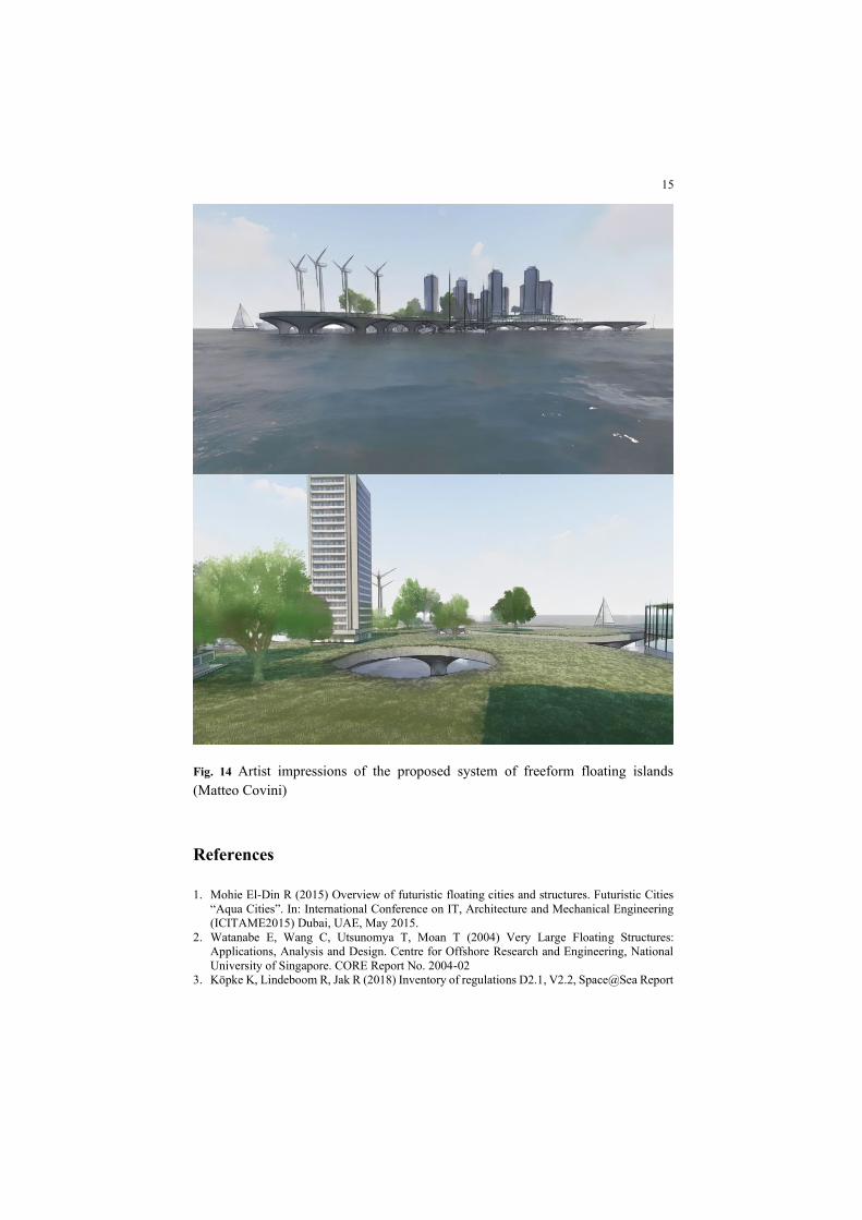
Fig. 14 Artist impressions of the proposed system of freeform floating islands
(Matteo Covini)
References
1. Mohie El-Din R (2015) Overview of futuristic floating cities and structures. Futuristic Cities
“Aqua Cities”. In: International Conference on IT, Architecture and Mechanical Engineering
(ICITAME2015) Dubai, UAE, May 2015.
2. Watanabe E, Wang C, Utsunomya T, Moan T (2004) Very Large Floating Structures:
Applications, Analysis and Design. Centre for Offshore Research and Engineering, National
University of Singapore. CORE Report No. 2004-02
3. Köpke K, Lindeboom R, Jak R (2018) Inventory of regulations D2.1, V2.2, Space@Sea Report

16
4. Bhooshan S, El Sayed M (2011) Use of sub-division surfaces in architectural form-finding and
procedural modelling. In: Proceedings of the 2011 Symposium on Simulation for Architecture
and Urban Design (SimAUD’11), San Diego, CA, USA. p 60–67
5. Halpern A, Billington D, Adriaenssens S (2013) The ribbed floor slab systems of Pier Luigi
Nervi. In: Obrębski J, Tarczewski R (eds) Proceedings of the International Association for
Shell and Spatial Structures (IASS) Symposium 2013, Wroclaw, Poland, September 2013.
6. Grünbaum B, Shephard G (1987) Tilings and Patterns. Freeman, San Francisco, CA, USA.
7. Visch G (2019) Method and system for forming structures in fluid, especially under water.
Patent NL2018969B1