PARAMETRIC CAD MODELING TO AID SIMULATION...
76
PARAMETRIC CAD MODELING TO AID SIMULATION-DRIVEN DESIGN an evaluation and improvement of methods used at Scania Linköping University | Department of Management and Engineering Master’s Thesis, 30 hp | Master of Science - Mechanical Engineering and Machine Design Spring 2017 | LIU-IEI-TEK-A--17/02807—SE Linköping University SE-581 83 Linköping, Sweden 013-28 10 00, www.liu.se Mattias Lokgård | Andreas Grandicki
Transcript of PARAMETRIC CAD MODELING TO AID SIMULATION...

PARAMETRIC CAD MODELING TOAID SIMULATION-DRIVEN DESIGNan evaluation and improvement ofmethods used at Scania
Linköping University | Department of Management and EngineeringMaster’s Thesis, 30 hp | Master of Science - Mechanical Engineering and Machine Design
Spring 2017 | LIU-IEI-TEK-A--17/02807—SE
Linköping UniversitySE-581 83 Linköping, Sweden
013-28 10 00, www.liu.se
Mattias Lokgård | Andreas Grandicki


Authors: Mattias Lokgård
M.Sc. Student in Mechanical Engineering
Linköping University, Sweden
Andreas Grandicki
M.Sc. Student in Mechanical Engineering
Linköping University, Sweden
Supervisors: Max Larsson
Design Engineer
Intake Components, NMGK
Scania CV AB, Sweden
Anton Wiberg
Ph.D. Student
IEI Machine Design
Linköping University, Sweden
Examiner: Johan Persson
Assistant Lecturer
IEI Machine Design
Linköping University, Sweden
Division of Machine Design Department of Management and Engineering
Linköping University SE-584 83 Linköping, Sweden
NMGK – Air Intake Components Engine Development
Scania CV AB SE-151 87 Södertälje, Sweden


Abstract
This report documents a thesis conducted at Scania CV AB in Södertälje, Sweden.The main purpose of the thesis has been to examine and improve upon current prac-tices of parametric CAD-modeling at Scania, with the ultimate goal of increased designautomation and simulation-driven design. The thesis was initiated with a literaturestudy, mainly covering the fields of parametric CAD-modeling, design automation andknowledge-based engineering. Furthermore, a questionnaire and multiple interviews wereconducted to assess the awareness and mind-set of the employees. Finally, a case-studywas carried out to follow current methodologies, and address any deficiencies found.
Some of the most important findings were that while parametric modeling has consider-able potential in enabling design automation, it is crucial, and most beneficial in terms ofautomation efficiency, to start with the fundamentals, namely achieving a uniform mod-eling practice. With these findings, a new proposed methodology has been introduced,as well as a recommended plan for a widespread implementation of parametric modelingat Scania. Such implementation would allow for shorter lead-times, faster adaptation tochanging conditions, and reduced development expenditures.
i

Acknowledgements
This thesis concludes a Master’s programme in Mechanical Engineering, at the Insti-tute of Technology at Linköping University. The thesis was conducted at Scania CVAB, Södertälje in the spring of 2017 over the duration of 20 weeks, corresponding to 30ECTS credits.
Firstly, we would like to extend our sincere gratitude and appreciation to Max Larsson,supervisor at Scania CV AB, for invaluable guidance, encouragement and support dur-ing the thesis work.
Secondly, we give our thanks to our supervisor, Anton Wiberg, and examiner, JohanPersson, at Linköping University, who have guided us through the thesis process. Wewould also like to thank our opponents, Munib Baber and Prajwal Shankar, for helpfuldiscussion and feedback throughout the thesis work.
Finally, we would like to thank Kim Petersson and Hannan Razzaq, at Scania CV ABfor arranging the thesis project. Furthermore, a sincere gratitude to the staff at theNMGK department of Scania CV AB for their cooperation and pleasant discussions.
Södertälje, June 2017
Mattias Lokgård Andreas Grandicki
ii

Acronyms & Nomenclature
CAD Computer Aided DesignCAE Computer Aided EngineeringCAM Computer Aided ManufacturingCFD Computational Fluid DynamicsDA Design AutomationDOE Design of ExperimentsFEM Finite Element MethodKBE Knowledge Based EngineeringPDM Product Data ManagementPLM Product Life-cycle ManagementVBA Visual Basic for Applications
iii

Contents
1. Introduction 11.1. Background . . . . . . . . . . . . . . . . . . . . . . . . . . . . . . . . . . . 11.2. Purpose & Goals . . . . . . . . . . . . . . . . . . . . . . . . . . . . . . . . 21.3. Research Questions . . . . . . . . . . . . . . . . . . . . . . . . . . . . . . . 21.4. Delimitations . . . . . . . . . . . . . . . . . . . . . . . . . . . . . . . . . . 2
2. Theoretical Framework 32.1. Parametric Modeling . . . . . . . . . . . . . . . . . . . . . . . . . . . . . . 3
2.1.1. Modeling Methods . . . . . . . . . . . . . . . . . . . . . . . . . . . 42.1.2. Design Space and Constraints . . . . . . . . . . . . . . . . . . . . . 5
2.2. Knowledge-Based Engineering . . . . . . . . . . . . . . . . . . . . . . . . . 62.2.1. KBE implementation in CATIA V5 . . . . . . . . . . . . . . . . . 72.2.2. KBE methodologies . . . . . . . . . . . . . . . . . . . . . . . . . . 72.2.3. Manufacturing Knowledge . . . . . . . . . . . . . . . . . . . . . . . 92.2.4. CAD-CAE handoff . . . . . . . . . . . . . . . . . . . . . . . . . . . 9
2.3. Implementation of Design Automation . . . . . . . . . . . . . . . . . . . . 102.3.1. Implementation Preparation . . . . . . . . . . . . . . . . . . . . . . 102.3.2. Implementation Strategy . . . . . . . . . . . . . . . . . . . . . . . 11
2.4. Multidisciplinary Design Optimization . . . . . . . . . . . . . . . . . . . . 132.5. Design of Experiments . . . . . . . . . . . . . . . . . . . . . . . . . . . . . 142.6. Manufacturing Methods . . . . . . . . . . . . . . . . . . . . . . . . . . . . 15
2.6.1. Casting Methods . . . . . . . . . . . . . . . . . . . . . . . . . . . . 162.6.2. Design Guidelines for Casting . . . . . . . . . . . . . . . . . . . . . 16
2.7. Design Process at Scania NMGK . . . . . . . . . . . . . . . . . . . . . . . 172.8. Previous Work at Scania . . . . . . . . . . . . . . . . . . . . . . . . . . . . 19
2.8.1. KBE capabilities in CATIA by Lundin and Sköldebrand [27] . . . 192.8.2. Methodology development by Luu [28] and Blomberg [3] . . . . . . 192.8.3. Methodology development by Jansson and Wiberg [25] . . . . . . . 20
3. Thesis Methodology 223.1. Data Collection . . . . . . . . . . . . . . . . . . . . . . . . . . . . . . . . . 22
3.1.1. Literature Study . . . . . . . . . . . . . . . . . . . . . . . . . . . . 233.1.2. Interviews & Questionnaire . . . . . . . . . . . . . . . . . . . . . . 23
3.2. Methodology Development . . . . . . . . . . . . . . . . . . . . . . . . . . . 243.2.1. Formulation of modeling methodology . . . . . . . . . . . . . . . . 243.2.2. Case Study Component . . . . . . . . . . . . . . . . . . . . . . . . 24
iv
4. Results 264.1. Interview Results . . . . . . . . . . . . . . . . . . . . . . . . . . . . . . . . 26
4.1.1. Information Collection . . . . . . . . . . . . . . . . . . . . . . . . . 264.1.2. Manufacturing Aspects . . . . . . . . . . . . . . . . . . . . . . . . 274.1.3. Parametric Modeling . . . . . . . . . . . . . . . . . . . . . . . . . . 27
4.2. Questionnaire Results . . . . . . . . . . . . . . . . . . . . . . . . . . . . . 294.2.1. Design Intent & Model Structure . . . . . . . . . . . . . . . . . . . 294.2.2. Knowledge-Based Engineering . . . . . . . . . . . . . . . . . . . . . 294.2.3. Information Exchange . . . . . . . . . . . . . . . . . . . . . . . . . 29
4.3. Methodology Development . . . . . . . . . . . . . . . . . . . . . . . . . . . 304.3.1. Information Collection . . . . . . . . . . . . . . . . . . . . . . . . . 304.3.2. Manufacturing Knowledge . . . . . . . . . . . . . . . . . . . . . . . 354.3.3. Parametric Modeling . . . . . . . . . . . . . . . . . . . . . . . . . . 354.3.4. Model Quality . . . . . . . . . . . . . . . . . . . . . . . . . . . . . 39
4.4. Final Methodology . . . . . . . . . . . . . . . . . . . . . . . . . . . . . . . 414.4.1. Pre-CAD phase . . . . . . . . . . . . . . . . . . . . . . . . . . . . . 414.4.2. CAD Modeling and Robustness Evaluation . . . . . . . . . . . . . 424.4.3. Exploration and Hand-off . . . . . . . . . . . . . . . . . . . . . . . 434.4.4. CAD Model Structure and Best Practices . . . . . . . . . . . . . . 44
5. Discussion 465.1. Discussion of Results . . . . . . . . . . . . . . . . . . . . . . . . . . . . . . 46
5.1.1. Information Collection . . . . . . . . . . . . . . . . . . . . . . . . . 465.1.2. Manufacturing Knowledge . . . . . . . . . . . . . . . . . . . . . . . 475.1.3. Parametric Modeling . . . . . . . . . . . . . . . . . . . . . . . . . . 475.1.4. Model Quality . . . . . . . . . . . . . . . . . . . . . . . . . . . . . 485.1.5. Environmental and Ethical Impact . . . . . . . . . . . . . . . . . . 49
5.2. Discussion of Methodology . . . . . . . . . . . . . . . . . . . . . . . . . . . 505.2.1. Case Study . . . . . . . . . . . . . . . . . . . . . . . . . . . . . . . 505.2.2. Data Collection . . . . . . . . . . . . . . . . . . . . . . . . . . . . . 50
6. Conclusion 516.1. Research Question 1 . . . . . . . . . . . . . . . . . . . . . . . . . . . . . . 516.2. Research Question 2 . . . . . . . . . . . . . . . . . . . . . . . . . . . . . . 516.3. Research Question 3 . . . . . . . . . . . . . . . . . . . . . . . . . . . . . . 52
7. Further Studies 53
Appendix A. Interview Guide (Design Engineers) 58
Appendix B. Questionnaire Results 60
v
List of Figures
1. Interpretation of the different design spaces by Cederfeldt [9] . . . . . . . 62. Interpretation of Parametric Design Roadmap by Bodein et al. [5] . . . . 133. Proposed methodology of Luu [28] and Blomberg [3] . . . . . . . . . . . . 194. Proposed methodology of Jansson and Wiberg [25] . . . . . . . . . . . . . 20
5. The methodology applied in this thesis . . . . . . . . . . . . . . . . . . . . 22
6. Overview of the Excel sheets . . . . . . . . . . . . . . . . . . . . . . . . . 307. The Interface Matrix . . . . . . . . . . . . . . . . . . . . . . . . . . . . . . 318. Updated Interface Matrix . . . . . . . . . . . . . . . . . . . . . . . . . . . 319. Revised Data Exchange Matrix . . . . . . . . . . . . . . . . . . . . . . . . 3210. Requirements and Constraints Matrix . . . . . . . . . . . . . . . . . . . . 3211. Updated Requirements and Constraints Matrix . . . . . . . . . . . . . . . 3312. Parameter Definition Matrix . . . . . . . . . . . . . . . . . . . . . . . . . 3413. Parameter Relations Matrix . . . . . . . . . . . . . . . . . . . . . . . . . . 3514. Base surfaces of the CAD-model . . . . . . . . . . . . . . . . . . . . . . . 3615. Progression of the surface model . . . . . . . . . . . . . . . . . . . . . . . 3716. Model tree structure . . . . . . . . . . . . . . . . . . . . . . . . . . . . . . 3817. A illustration of the iterative modeling process . . . . . . . . . . . . . . . 3918. Solid models generated by the DOE sequence . . . . . . . . . . . . . . . . 4019. Final Methodology . . . . . . . . . . . . . . . . . . . . . . . . . . . . . . . 4120. Updated Overview of the Excel sheets . . . . . . . . . . . . . . . . . . . . 4121. Design of Experiments with successful and failed designs . . . . . . . . . . 4322. Adaptation of the Design Space . . . . . . . . . . . . . . . . . . . . . . . . 44
vi

1. Introduction
This Master’s thesis has been performed at the NMGK group of Scania CV AB (Scania),which is responsible for the development of engine intake components. Their goals areto create product documentation for manufacturing, ensure the products functionalityand life span, in balance with the demands on product properties, production, serviceand purchasing strategies. This challenges the engineers to meet demands from multipledisciplines, which often tends to change during the course of a project.
Parametric CAD (Computer Aided Design) is a modeling method that allows the engi-neers to cope with quick and sudden changes to the design whilst gaining a more efficientdesign process. Parametric models can, at a later stage in the process, be used to verifyand optimize the design, through e.g. CFD (Computational fluid dynamics) and FEM(Finite element method). The following thesis will strive to enable the incorporationof design requirements and knowledge from multiple disciplines early on in the designprocess by using parametric modeling techniques, to potentially increase productivitywhile ensuring manufacturability.
1.1. Background
The current design process at Scania is largely iterative, where the design engineers se-quentially gather information from the different departments such as CFD, FEM andproduction. Experience has shown that the feedback from these departments often ar-rive late in the process, causing unnecessary expenses of time and resources due to theincreased number of design iterations. By integrating intelligence and design require-ments into the models at an early stage, it is possible to satisfy the needs of multipledepartments from the start, potentially reducing errors and costly changes later on inthe development process. Previous theses at Scania has produced methodologies for cre-ating parametric CAD models, however, their results has not yet been implemented tothe extent presented.
1
1.2. Purpose & Goals
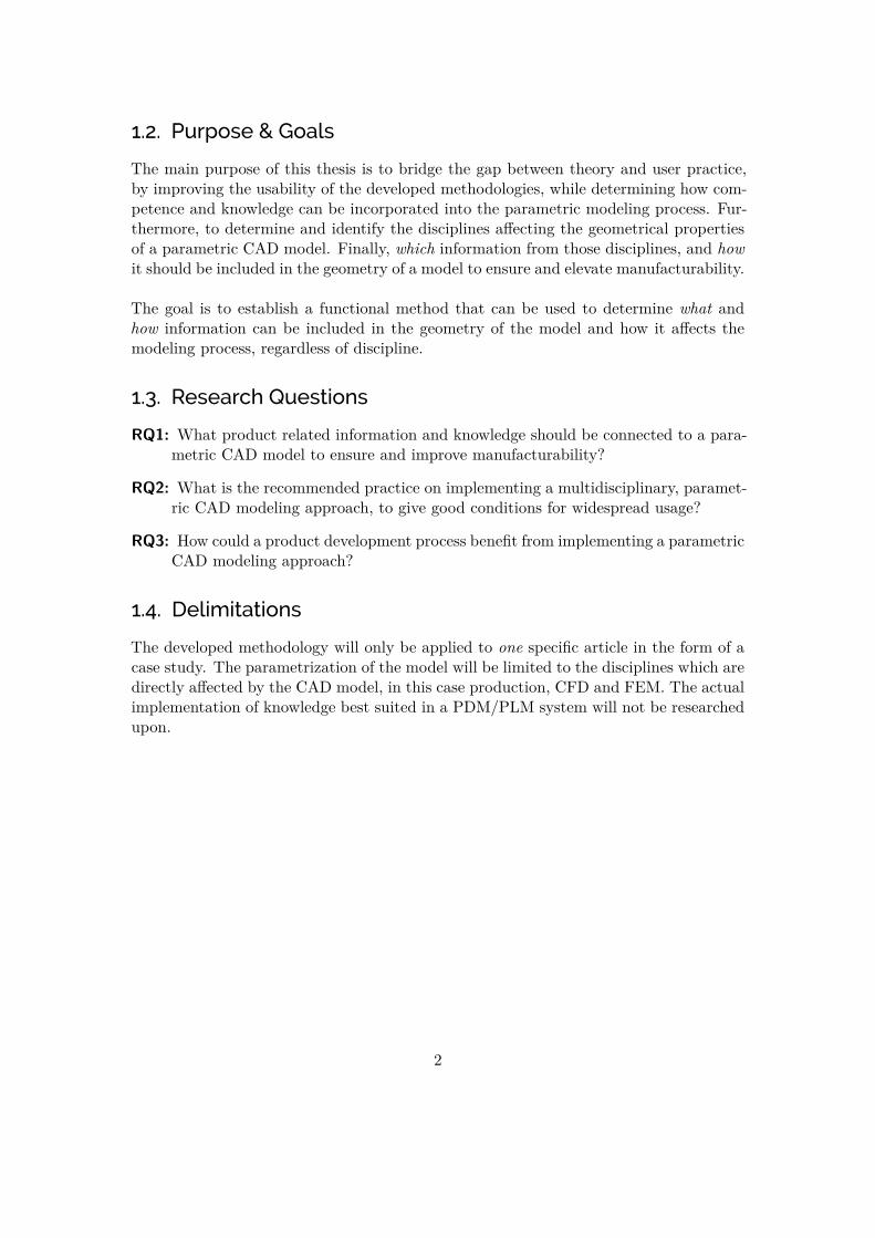
The main purpose of this thesis is to bridge the gap between theory and user practice,by improving the usability of the developed methodologies, while determining how com-petence and knowledge can be incorporated into the parametric modeling process. Fur-thermore, to determine and identify the disciplines affecting the geometrical propertiesof a parametric CAD model. Finally, which information from those disciplines, and howit should be included in the geometry of a model to ensure and elevate manufacturability.
The goal is to establish a functional method that can be used to determine what andhow information can be included in the geometry of the model and how it affects themodeling process, regardless of discipline.
1.3. Research Questions
RQ1: What product related information and knowledge should be connected to a para-metric CAD model to ensure and improve manufacturability?
RQ2: What is the recommended practice on implementing a multidisciplinary, paramet-ric CAD modeling approach, to give good conditions for widespread usage?
RQ3: How could a product development process benefit from implementing a parametricCAD modeling approach?
1.4. Delimitations
The developed methodology will only be applied to one specific article in the form of acase study. The parametrization of the model will be limited to the disciplines which aredirectly affected by the CAD model, in this case production, CFD and FEM. The actualimplementation of knowledge best suited in a PDM/PLM system will not be researchedupon.
2

2. Theoretical Framework
The theoretical framework of the thesis covers previous work performed at Scania inaddition to literature in the thesis field. The previous work is the foundation and startingpoint for this thesis. Additionally, areas that have been deemed relevant for designautomation and more specifically parametric CAD modeling for multidisciplinary designhas been covered, such as parametric modeling and knowledge-based engineering.
2.1. Parametric Modeling
Parametric CAD-models can be developed in modern CAD applications and allows en-gineers to efficiently alter and modify geometry without having to recreate the model.The parametrization of CAD-models can be performed on different levels [39, 1, 10], butthey can all, in some sense, elevate the quality and the re-usability of a CAD-model.Furthermore, re-using CAD-models can decrease the lead time of the product develop-ment process if defined and used properly [7].
Parametric modeling refers to the creation of geometry that is controlled and definedby non-geometric features called parameters. Parameters can be controlled through con-straints based on geometry, dimensions or logic expressions [7]. Cederfeldt and Sunnersjö[10] suggests that parametric modeling could be used to ”achieve a flexible design at anearly design stage”. With a flexible design early in the design process, it is possiblefor the designer to adapt quicker to changes that might occur downstream in the prod-uct development process. The level and complexity of how the parameters are controlledand what they control, depends on the design intent and design space of the CAD model.
According to Tarkian [39] and Amadori [1], geometrical transformations of CAD mod-els can be divided into two categories, morphological and topological transformations.Morphological transformations are geometrical changes made within one instance of aCAD model, i.e. the geometry does not require more information than the informationstored within the given instance to re-evaluate and regenerate. Topological transfor-mations occurs on a higher level than morphological transformations, and is a way toeffectively alter a models topology, i.e. increase, replace or reuse geometrical objects andfeatures. Topological transformations are therefore a way of controlling morphologicaltransformations driven by the surrounding context.
3

2.1.1. Modeling Methods
Multiple general methods for creating parametric and robust CAD models has beenexamined in previous work conducted at Scania [28, 3], as summarized;
• PARAMASS, as explained by Salehi-Douzloo [34], is a methodology divided intothree main phases; specification, where the parameters and relations to be includedin the model are determined, to capture the information and knowledge desired.This is arguably the most important phase. The results of this phase is docu-mented in two matrices called Parameter Structure Matrix (PSM) and AssociativeStructure Matrix (ASM). The second phase, structuring and creation, is where theactual model is created. The phase involves decomposing the model to increase there-usability and decrease the complexity. The final phase, modification, is wherethe model can be modified with help of parameters and relations in a robust way.
• Explicit Reference Modeling Methodology, as introduced by Bodein et al. [6],is a methodology focusing on the modeling of parts. The aim of the methodologyis to achieve a more uniform and consistent modeling structure, yielding benefitssuch as increased model understanding among designers, increased efficiency andreusability. This is achieved by decomposing the part into simpler solids (few topo-logical modifications per operation) and the use of explicit references to geometrycreated by the user, reducing the amount of parent-child relationships. The solidsare then assembled using boolean operations, which increases the robustness of themodel. Furthermore, Bodein et al. [6] proposes that all dress-up features (such asfillets and chamfers) are to be created as close to their defining solid as possible.
• Resilient Modeling Strategy, as presented by Gebhard [15], is a ”best-practices”guide to creating robust and reusable CAD-models. As Gebhard [15] explains,parent-child relationships may be a source of instability in the model, which mightnot become evident until the model is modified (often a long time after the creation,and/or by someone other than the initial designer). The methodology strives toyield editable, obvious and reusable models. This is achieved by structuring thefeature tree in a standardized manner, by the purpose of the features. The proposedstructure is;
1. Ref: reference entities2. Construction: entities which aid the creation of complex solids3. Core: features defining the core shape of the model4. Detail: features adding small features, linking to Ref and Core5. Modify: ”features that transform faces or replicate features”6. Quarantine: ”isolates volatile features at the end of the tree” (e.g. dress-up
features)
4

Furthermore, Gebhard [15] describes that the model structure should aim to beobvious rather than intuitive, as the latter is dependent on the designer and itsexperience. By using obvious naming of features, the design intent can be kept.Finally, the use of parametric models is advocated to allow generation of multipleconfigurations, to assure reusability. As Gebhard [15] explains, conformity to theseguidelines can be assured by the use of pre-release checklists.
2.1.2. Design Space and Constraints
Determining how a parametric CAD model should be developed and what informationand knowledge are to be included as design parameters, is largely dependent on howknowledgeable the design engineer is of the design process [9]. In addition, the knowl-edge on how a product is to be manufactured and what the performance requirementsare, is imperative to set limitations to those parameters.
Limitations to the design parameters is what defines the actual design space. The ac-tual design space is what describes physical constraints of the product, demands fromthe customer, manufacturing, and other constraint spaces that affect the design of theproduct. As a design engineer it is important to evaluate and prioritize these constraintsin order to define the designs constraint-boundaries.
Cederfeldt [9] discusses the importance of defining the constraint-boundaries and illus-trates the actual design space with surrounding design spaces (Figure 1). Furthermore,Cederfeldt [9] suggests that the different design spaces are limiting the number of rele-vant design proposals, i.e. it is irrelevant to develop a design that meets all customerrequirements but can’t be manufactured.
In Figure 1, Cederfeldt [9] defines six different design spaces. The design spaces aredescribed on a generic level, and may therefore look different depending on product andindustry.
• ”Infinite” Design Space: Limited by the laws of nature.
• Physical Design Space: Limits the infinite design space even further by declaringwhats possible to create and produce.
• Customer Space: Representing the demands and wishes from customers.
• Product Design Space: Limits the physical design space which is dependent onhow a company have defined their product design configuration.
• Company Design Space: Limits the physical design space based on resource andmanufacturing limitations.
• Actual Design Space: Limited by the design spaces above to describe the numberof relevant design proposals.
5

Figure 1.: Interpretation of the different design spaces by Cederfeldt [9]
2.2. Knowledge-Based Engineering
Knowledge-Based Engineering, or KBE for short, is a broad term describing methodsto streamline and automate the engineering design process. While its definition variesdepending on author and perspective, many of its aspects has been captured and sum-marized by La Rocca [26];
”Knowledge based engineering (KBE) is a technology based on the use ofdedicated software tools called KBE systems, which are able to capture andsystematically reuse product and process engineering knowledge, with the fi-nal goal of reducing time and costs of product development by means of thefollowing:
– Automation of repetitive and non-creative design tasks– Support of multidisciplinary design optimization in all the phases of the
design process” [26]
While KBE is often described as having great potential for improving the engineeringdesign process, its implementation and amount of available literature has so far beenlacking, partly due to its applications being limited to the most complex engineeringfields [26, 41]. However, as competition increases in all fields, KBE is becoming an in-creasingly interesting topic to study [41].
6

Main elements of KBE includes identifying relevant knowledge, embedding it into a KBEapplication, and ease the reuse of such knowledge [26]. La Rocca [26] also describes howKBE is commonly implemented in modern CAD applications programmatically as rules,utilizing logic reasoning combined with provided knowledge and facts. Thus, a specificset of inputs will always yield the same output.
As Verhagen et al. [41] explains, it currently does not exist a universal method of deter-mining whether KBE is beneficial to implement for a specific article or situation. How-ever, La Rocca [26] argues that situations which are associated with multidisciplinaryaspects, repetitive work through geometry modification or reconfiguration, both wouldfavor the use of KBE. Furthermore, La Rocca [26] describes how KBE could enable theuse of MDO (Multidisciplinary Design Optimization), as multiple configurations andmaterial for CAE (Computer Aided Engineering) could be automatically generated. Inthe traditional engineering design process, the manual handling required for MDO wouldmost likely be unfeasible.
As described by La Rocca [26], some of the main difficulties in implementing KBE maybe;
• Licencing costs, which are often required to allow the implementation of KBEin the CAD application.
• Lack of metric, to quantify the benefit and profit of implementation.
• Lack of know-how, as the implementation is associated with a certain learning-curve.
Furthermore, the extensive use of programming, while being a powerful method of im-plementing KBE, may be intimidating to the traditional CAD user, which highlights theimportance of proper learning material [26].
2.2.1. KBE implementation in CATIA V5
As in many modern CAD programs, CATIA V5 has specific workbenches, i.e. collectionsof tools, allowing the user to develop KBE applications directly within the modeling en-vironment. The most common and accessible tools consists of formulas, rules, reactionsand checks, available in the knowledge advisor (KWA) workbench. The use of program-ming through CAA (API1 of CATIA [33]), allows for even more complex operations[4].
2.2.2. KBE methodologies
A number of methodologies for developing and maintaining KBE applications exist, andsome of the most common methodologies will be summarized below;
1Application Programming Interface
7

MOKA, or Methodology and tools Oriented to knowledge-based engineering Applications,can be summarized in the following steps [12, 41];
“1. Identify: Determine needs and technical feasibility2. Justify: Validate scope and assess risks3. Capture: Collect and structure the raw knowledge4. Formalise: Develop Product and Process models5. Package: Develop application6. Activate: Introduce, use and maintain” [12, 41]
As explained by Curran et al. [12] and Verhagen et al. [41], MOKA distinguishes betweeninformal and formal models, where the informal models are utilized to capture and storeknowledge in a format suitable for humans, while formal models adapt the knowledgeto a format suitable for computer processing [36]. The informal models are defined us-ing ICARE forms (Illustrations, Constraints, Activities, Rules and Entities), while theformal models are defined using the so called Moka Modelling Language (MML) [12].
KNOMAD, which stands for Knowledge Nurture for Optimal Multidisciplinary Anal-ysis and Design, is as the name implies a KBE methodology for implementation ofmultidisciplinary knowledge [12]. The methodology is aimed to improve earlier method-ologies, such as MOKA, to better incorporate aspects related to multidisciplinary designoptimization and the implementation into the design process [12]. A brief overview ofthe steps in KNOMAD [12];
• Knowledge capture: information and knowledge of interest is collected eitherfrom previously documented sources or existing expertise, and is documented.
• Normalisation: the quality of the collected knowledge is assessed to determinewhether it should be included or not, and the knowledge is normalised.
• Organisation: the knowledge is organised to allow for easy and automatic re-trieval among the stakeholders. Here, a specific ontology can be introduced, i.e. aclassification and definition of the domain and its content. The ontology aid informalizing the knowledge.
• Modeling: the product is modelled, and by use of parameters and knowledgedefined using the ontology introduced in previous steps, each discipline involved isprovided with a specific model. The models are documented in a report.
• Analysis: each of the disciplines involved analyze their respective model andassess the performance, in regards to the specific discipline. This step may involveoptimization.
• Delivery: the feasibility of an optimized solution is ensured, after which it isdelivered to the stakeholders.
8

2.2.3. Manufacturing Knowledge
As explained by Gembarski et al. [16], guidelines for manufacturing methods in the prod-uct development process has had widespread use for a long time, however, they oftenconsist of implicit and heuristic knowledge, thus relying on the skill and experience ofthe engineer to translate these into explicit knowledge. Gembarski et al. [16] introducesa framework for the integration of manufacturing knowledge into CAD-models, by theoperationalization of manufacturing restrictions, i.e. translating ratings such as ”good”or ”bad” when referring to the manufacturability of products into parameters and ruleswhich can be implemented into a CAD model using KBE.
Gembarski et al. [16] utilizes the theory of Characteristics-Properties Modelling/PropertyDriven Development (CPM/PDD), which features a differentiation between the followingthree elements influencing or influenced by the product;
• Characteristics: parameters which can be directly altered by the engineer, suchas geometric dimensions and choice of material [16]. Characteristics are oftenadded and altered inside a CAD-environment.
• Properties: parameters which can not be directly altered by the engineer, butare rather resulting from the characteristics, such as component weight or stressdistribution [16]. Properties are often examined using CAE-tools.
• External Conditions: conditions which restrict the design space, e.g. availablemanufacturing methods and connecting interfaces [16].
Furthermore, synthesis is described as the process of altering a products characteristicsto yield a desired property, and analysis is described as the process of verifying thatthe product reaches the requirements imposed upon it [16]. Thus, several iterations ofsynthesis and analysis may be required until all requirements are met.
2.2.4. CAD-CAE handoff
As discussed by Corallo et al. [11], the hand-off between CAD and CAE departmentsoften require the creation of so called context models, i.e. simplified models intendedfor various CAE analyses, as it might be disadvantageous to send the complete CADmodel. Common tasks in creating a context model is simplification of geometry andconversion to a neutral file format. The preparation of these models is often a tediousand time-consuming process, requiring the design engineer to possess specific knowledgein CAE. Corallo et al. [11] investigated the benefits of developing KBE applications tofacilitate and automate this model preparation and hand-off (in the aerospace industry),and found major efficiency improvements.
9

2.3. Implementation of Design Automation
Design Automation (DA) is a collection name of methodologies and theories that allowsbusinesses to ”cut lead times, workloads, and ultimately costs in order to become morecompetitive” [9]. The implementation of a DA-system could become a tedious task, andjust like most implementation projects, requires proper planning where it is essential toidentify and define a need and potential of the system to be implemented. [9] The idea isto automate repetitive and monotone design tasks, which would allow designers to focuson more problem-solving, creative and value-adding work [39, 1, 9]. Design automationcovers tools and methodologies related to improving the design process, e.g. parametricmodeling, PDM, PLM and KBE.
2.3.1. Implementation Preparation
Ferreira et al. [14] and Siddiqui et al. [35], claims that the problem today is no longer thetechnology, as technology and knowledge is something that is available and exists. Theissue is how to best streamline the process of how to capture, use and re-use the knowl-edge through the technology. Businesses have different processes and ways of working,which results in a need to uniquely tailor the implementation of a design automationsystem to given business.
An implementation project of a DA-system could result in a significant change in thedesign process and overall business process. Salehi-Douzloo [34] means that the planningof a methodology implementation can be compared with the planning of a product de-velopment process, which could result in a complex, long and critical process. Luu [28]mentioned in his work, ”Changes are stressful whether they are positive or negative andcan therefore be met with resistance”, referring to the implementation of such a method-ology in an organization. Design automation is in itself a type of methodology andshould therefore follow the same principles as any design implementation methodology.Cederfeldt [9] developed a structured method and approach for implementing designautomation systems on a larger scale. He discusses the importance to incorporate theusers into the planning phase to make the system usable for the intended users.
Siddiqui et al. [35], describes the process of implementing a PDM-system for the firsttime in an organization. A PDM-system and its functionality is the core foundation fora successful design automation implementation. The system acts like a communicationtool between the different organizational disciplines and their software [35, 9]. Siddiquiet al. [35] further describes the reasons for a successful implementation which, if followed,could result in a better used and user-friendly system;
• good preparation and implementation;• good education and training of employees;• clear strategy and specification of business processes;• good evaluation and selection of suitable systems.
10
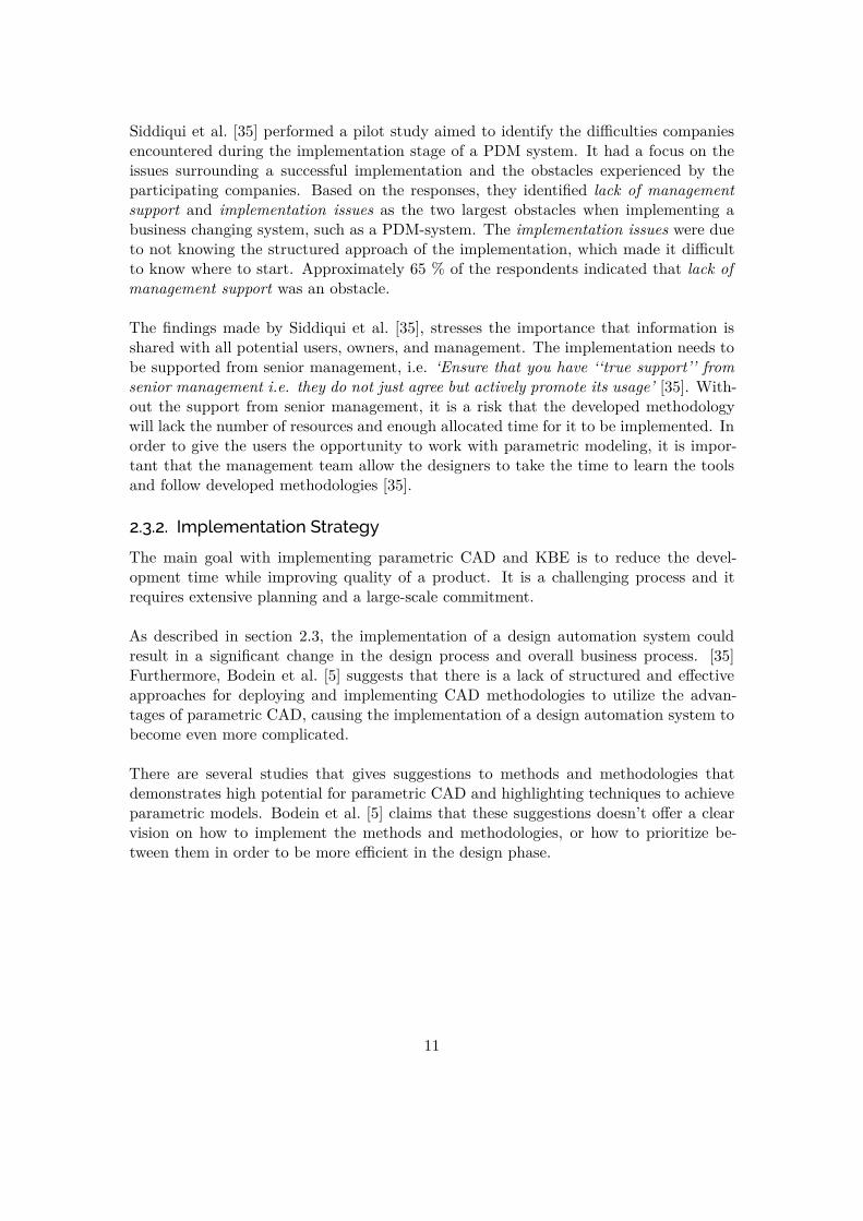
Siddiqui et al. [35] performed a pilot study aimed to identify the difficulties companiesencountered during the implementation stage of a PDM system. It had a focus on theissues surrounding a successful implementation and the obstacles experienced by theparticipating companies. Based on the responses, they identified lack of managementsupport and implementation issues as the two largest obstacles when implementing abusiness changing system, such as a PDM-system. The implementation issues were dueto not knowing the structured approach of the implementation, which made it difficultto know where to start. Approximately 65 % of the respondents indicated that lack ofmanagement support was an obstacle.
The findings made by Siddiqui et al. [35], stresses the importance that information isshared with all potential users, owners, and management. The implementation needs tobe supported from senior management, i.e. ‘Ensure that you have ‘‘true support’’ fromsenior management i.e. they do not just agree but actively promote its usage’ [35]. With-out the support from senior management, it is a risk that the developed methodologywill lack the number of resources and enough allocated time for it to be implemented. Inorder to give the users the opportunity to work with parametric modeling, it is impor-tant that the management team allow the designers to take the time to learn the toolsand follow developed methodologies [35].
2.3.2. Implementation Strategy
The main goal with implementing parametric CAD and KBE is to reduce the devel-opment time while improving quality of a product. It is a challenging process and itrequires extensive planning and a large-scale commitment.
As described in section 2.3, the implementation of a design automation system couldresult in a significant change in the design process and overall business process. [35]Furthermore, Bodein et al. [5] suggests that there is a lack of structured and effectiveapproaches for deploying and implementing CAD methodologies to utilize the advan-tages of parametric CAD, causing the implementation of a design automation system tobecome even more complicated.
There are several studies that gives suggestions to methods and methodologies thatdemonstrates high potential for parametric CAD and highlighting techniques to achieveparametric models. Bodein et al. [5] claims that these suggestions doesn’t offer a clearvision on how to implement the methods and methodologies, or how to prioritize be-tween them in order to be more efficient in the design phase.
11
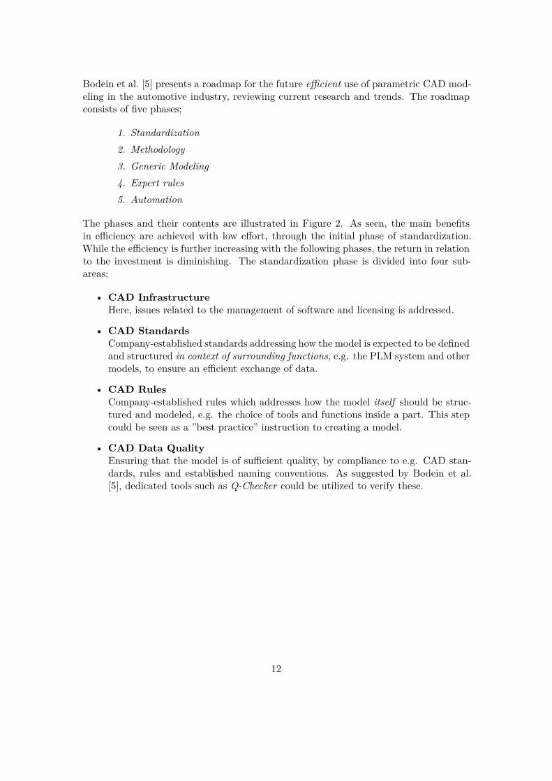
Bodein et al. [5] presents a roadmap for the future efficient use of parametric CAD mod-eling in the automotive industry, reviewing current research and trends. The roadmapconsists of five phases;
1. Standardization2. Methodology3. Generic Modeling4. Expert rules5. Automation
The phases and their contents are illustrated in Figure 2. As seen, the main benefitsin efficiency are achieved with low effort, through the initial phase of standardization.While the efficiency is further increasing with the following phases, the return in relationto the investment is diminishing. The standardization phase is divided into four sub-areas;
• CAD InfrastructureHere, issues related to the management of software and licensing is addressed.
• CAD StandardsCompany-established standards addressing how the model is expected to be definedand structured in context of surrounding functions, e.g. the PLM system and othermodels, to ensure an efficient exchange of data.
• CAD RulesCompany-established rules which addresses how the model itself should be struc-tured and modeled, e.g. the choice of tools and functions inside a part. This stepcould be seen as a ”best practice” instruction to creating a model.
• CAD Data QualityEnsuring that the model is of sufficient quality, by compliance to e.g. CAD stan-dards, rules and established naming conventions. As suggested by Bodein et al.[5], dedicated tools such as Q-Checker could be utilized to verify these.
12

Figure 2.: Interpretation of Parametric Design Roadmap by Bodein et al. [5]
2.4. Multidisciplinary Design Optimization
Multidisciplinary Design Optimization (MDO), as described by Martins and Lambe [29],concerns methods of applying numerical optimization to coupled systems involving sev-eral disciplines, i.e. systems where the performance is not merely determined by the in-dividual disciplines, but their interactions as a whole. Possible benefits of MDO includesreduced development time and thus cost [29], however, the method is computationallyexpensive. As Sobieszczanski-Sobieski and Haftka [37] explains, the computational costdoes not simply increase as a sum of the individual optimization problems of each dis-cipline, but at an even higher rate. The computational cost can however be reduced atthe expense of accuracy, by the use of various approximation techniques [37], such asmeta-models [8].
13

2.5. Design of Experiments
Antony [2] defines a process as a ”...transformation of inputs into outputs”. Furthermore,Design of Experiments (or DOE) is described as a method of efficiently gaining knowl-edge about the input/output relations of a process. As described by Cavazzuti [8], DOEis ”...a way of choosing samples in the design space in order to get the maximum amountof information using the minimum amount of resources...”. When DOE is performed, de-liberate changes are made to the input variables, and the subsequent changes in outputsare observed. By use of statistical methods, models can be created from the observeddata [2], which can be used to predict the process response. One such approximatemethod is response surfaces, also called meta-models [8]. Several methods of performingDOE exist, i.e. how to sample the design space efficiently. Common methods includeLatin Hypercube, Full Factorial, Central Composite and Random sampling [8].
14

2.6. Manufacturing Methods
Choosing the best technical and economical casting method for manufacturing can be adifficult process. High cost in the casting process does not necessarily imply a more ex-pensive end product. It is important to look at the total cost, e.g. if the manufacturingprocess requires after-treatment of the component or not.
The component production quantity is a critical parameter when it comes to selectingthe casting method. Different casting methods sets different limitations on the castings,the equipment and its tools. The castings geometry, i.e. the model to be manufactured,is typically affected by the casting method, which could result in a costly process if notconsidered in the earlier stages of product development.
When the product is being developed in a CAD environment the designer engineer needsto follow certain requirements in order to meet the demands from the manufacturer. Thefollowing are typical component requirements that needs to be considered when decidingon a manufacturing method;
• Material
• Quantity
• Dimensional Accuracy
• Surface Roughness
• Cargo Weight
• Geometrical shape
• Cost
Depending on the component requirements, a decision needs to be made on what castingmethod is the most suitable for the component. Depending on the chosen casting methodcertain materials might be more or less suited for casting. Once the casting method havebeen chosen and the material is selected, some alterations and modifications might haveto be performed to the component. It is at this stage possible to optimize and verify thedesign based on the casting method and feedback from the manufacturer.
15

2.6.1. Casting Methods
These are some of the most commonly used casting methods at Scania (NMGK);
• Die Casting (High Pressure Die Casting) is a method where pressurized, moltenmetal is injected into a permanent mold consisting of two or more dies. After themetal is solidified, the molds are separated and the part is ejected. The methodprovides good dimensional accuracy, surface finish, repeatability and is able toproduce complex geometries with thin features [17, 38]. However, large productionvolumes are often required as the tooling cost is relatively high [38].
• Chill Casting2 (Gravity Die Casting) utilizes gravity to fill a permanent moldwith molten metal. As the method permits the use of disposable sand cores, com-plex geometries with undercut internal features can be produced, which would bedifficult or impossible using metal cores [38]. The tooling is cheaper than for diecasting, making smaller production volumes feasible.
• Sand Casting is a method using disposable molds created from sand. The moltenmetal is injected under low or atmospheric pressure. The tooling is cheap, makingsmaller production volumes feasible [38]. As the thermal conductivity of the sandis lower than that for metal (of which the molds in die casting and chill casting aremade), the cooling rate is slower which leads to worse mechanical properties [17].
2.6.2. Design Guidelines for Casting
The casting process can present some complications, requiring planning during the designstage to avoid manufacturing defects. Special care needs to be taken to compensate forthe material shrinkage during solidification [17]. The following guidelines are commonfor all casting methods mentioned above;
• All walls/geometry which are perpendicular to the parting plane (called partingline in 2D) needs to have a draft angle, to facilitate withdrawal from the moldhalves [38].
• To reduce the cost and increase the dimensional accuracy, it is desirable to haveas few cores as possible, or ideally none at all.
• Uniform thickness is to be preferred to reduce the risk of porosity and shrinkagecracks during solidification.
• Sharp edges are to be avoided to reduce stress concentrations, hot spots and cracks.
2Kokillgjutning in Swedish
16
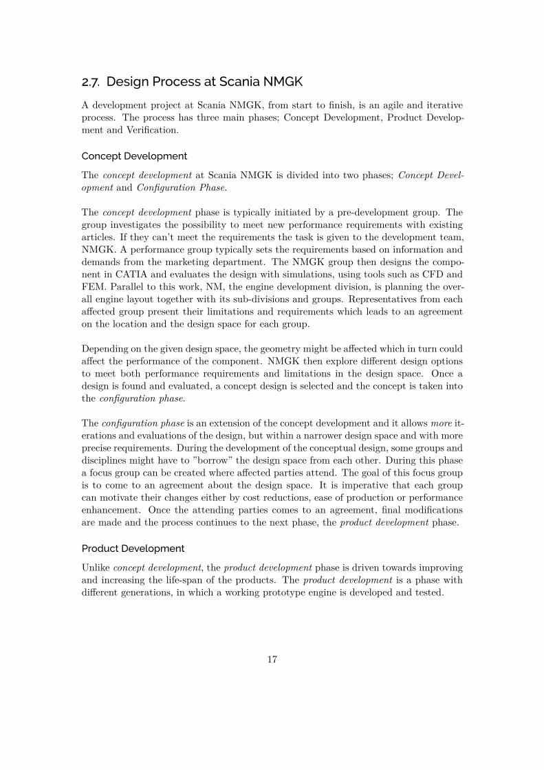
2.7. Design Process at Scania NMGK
A development project at Scania NMGK, from start to finish, is an agile and iterativeprocess. The process has three main phases; Concept Development, Product Develop-ment and Verification.
Concept Development
The concept development at Scania NMGK is divided into two phases; Concept Devel-opment and Configuration Phase.
The concept development phase is typically initiated by a pre-development group. Thegroup investigates the possibility to meet new performance requirements with existingarticles. If they can’t meet the requirements the task is given to the development team,NMGK. A performance group typically sets the requirements based on information anddemands from the marketing department. The NMGK group then designs the compo-nent in CATIA and evaluates the design with simulations, using tools such as CFD andFEM. Parallel to this work, NM, the engine development division, is planning the over-all engine layout together with its sub-divisions and groups. Representatives from eachaffected group present their limitations and requirements which leads to an agreementon the location and the design space for each group.
Depending on the given design space, the geometry might be affected which in turn couldaffect the performance of the component. NMGK then explore different design optionsto meet both performance requirements and limitations in the design space. Once adesign is found and evaluated, a concept design is selected and the concept is taken intothe configuration phase.
The configuration phase is an extension of the concept development and it allows more it-erations and evaluations of the design, but within a narrower design space and with moreprecise requirements. During the development of the conceptual design, some groups anddisciplines might have to ”borrow” the design space from each other. During this phasea focus group can be created where affected parties attend. The goal of this focus groupis to come to an agreement about the design space. It is imperative that each groupcan motivate their changes either by cost reductions, ease of production or performanceenhancement. Once the attending parties comes to an agreement, final modificationsare made and the process continues to the next phase, the product development phase.
Product Development
Unlike concept development, the product development phase is driven towards improvingand increasing the life-span of the products. The product development is a phase withdifferent generations, in which a working prototype engine is developed and tested.
17

Each generation starts with model development in CAD, but unlike the concept develop-ment phase, this CAD development is more driven to make the model manufacturablewhilst optimizing the performance. Approximately halfway into the phase, a designfreeze halts the modeling process which allows the groups to order their products forthe upcoming assembling of the prototype engine. Once the engine is assembled, theengine is tested for longer periods of time to simulate the life-expectancy of the enginecomponents.
Once the testing is done, the groups reviews the result and suggests improvements tothe next design iteration. The suggested improvements are implemented in the designand tested in the next prototype engine. If all requirements are met and the productswithstand the tests and simulations, they are further improved and prepared for massproduction.
Verification
The Verification phase is the last step in the development process. In the last phasethe last small changes can be made for the final prototype engine. Once the enginepasses the tests and meets the given requirements, they can start sending the productsto manufacturing. The development process concludes with a lessons-learned which getsdocumented to ensure implementation in future projects.
Some of the design related information is collected in an Excel spreadsheet, a designguideline, where the information is documented with a risk assessment and contingencyplan. The design guidelines (unique for each group), aids in ensuring improvement ofproduct quality and manufacturability.
18

2.8. Previous Work at Scania
Previous theses at Scania has had similar purpose and objectives as this thesis [28, 3,25, 31], i.e. developing methodologies for creating parametric CAD models. Precedingthese, a thesis work examined the possibilities of implementing KBE in CATIA V5 [27].The following section will provide a short review of previous work.
2.8.1. KBE capabilities in CATIA by Lundin and Sköldebrand [27]
The capabilities of CATIA V5 in regards to KBE has been thoroughly examined in pre-vious theses. From the work conducted by Lundin and Sköldebrand [27] (2008), it wasconcluded that a specific group of experts working with KBE would be beneficial forScania, aiding with the implementation and maintenance of parametric models. Thiswas reinforced by Blomberg [3], however, at the time of writing this has yet to be imple-mented. Moreover, as discussed by [27], simpler knowledge in the form of tools such asrules, reactions and checks in CATIA V5, while lacking the potential of pure program-ming tools, could more easily be implemented without the support of a specific expertgroup.
Furthermore, interviews conducted by Lundin and Sköldebrand [27] revealed a strongopinion of the intended users that the knowledge embedded in the models should notinhibit the work of the designer, but rather advise and alert. This raised the possibilityand desire of documenting the recommendations and advice typically ignored by theuser, to gain a better understanding of the model history.
2.8.2. Methodology development by Luu [28] and Blomberg [3]
Two theses [28, 3] were conducted simultaneously during 2015, with the same purposeand goals, i.e. developing a methodology for parametric CAD modeling in CATIA V5,with special focus on CFD. Case studies on a turbine volute and on intake ports wereused in the two studies. The final methodology was created by merging the results fromthe two theses.
Figure 3.: Proposed methodology of Luu [28] and Blomberg [3]
19

The proposed methodology of Luu [28] and Blomberg [3] which is divided into threemain phases, can be seen in Figure 3. The first phase, pre-CAD, takes place before theusage of any CAD tools, as the name implies. Here, any information necessary to createa parametric model is established and collected, such as interfaces, required parameters(and their relationships), and desired outputs to various departments. This is done bymeeting with various stakeholders, and documenting the progress in an established Ex-cel spreadsheet which is unique for the article. The spreadsheet contains a number ofmatrices based on PARAMASS [34, 28] (see subsection 2.1.1).
The second phase, CAD, is where the actual modeling takes place. The phase includesmoments such as decomposition into simpler sub-geometries and parameter creation.Emphasis is put on organizing the model structure, renaming features logically andmaking sure the model is stable. The phase is partly based on Explicit Reference Mod-eling Methodology [6] and Resilient Modeling Strategy [15] (see subsection 2.1.1).
The third and final phase, evaluation, is used to ensure the robustness of the model andcompliance with the steps in the methodology. The robustness is checked by performingDOE (see section 2.5), which is integrated in the previously mentioned Excel-spreadsheet.By using checklists, compliance with the methodology is ensured (partly based on Re-silient Modeling Strategy [15] see subsection 2.1.1).
2.8.3. Methodology development by Jansson and Wiberg [25]
As a continuation of the methodology created by [28, 3], further studies were conductedin 2016 by Jansson and Wiberg [25]. Case studies of a compressor wheel and a compressorvolute were made, to further develop and expand the methodologies of [28, 3]. The newmethodology had, contrary to earlier work, a larger focus on multi-disciplines, i.e. toincorporate requirements and knowledge not only from CFD by also FEM and to someextent manufacturing.
Figure 4.: Proposed methodology of Jansson and Wiberg [25]
20

The methodology created by [28, 3] was used as a starting point for the development,which becomes evident when comparing Figure 3 and Figure 4, where the initial phasesare similar. There are however some differences, especially in the evaluation phase. Asdescribed by [25], an initial FE-analysis has been added (using GPS/GAS3), to give thedesign engineer an indication of the performance and reduce the number of iterationsbetween the design- and CAE-engineers. Furthermore, as described by [25], this canallow for basic optimization of the component, possibly in PEO4. As discovered byJansson and Wiberg [25], the developed methodologies by Luu [28], Blomberg [3], andJansson and Wiberg [25] has apparent similarities with the KNOMAD methodology, seesubsection 2.2.2.
3Generative Part Structural Analysis, Generative Assembly Structural Analysis: workbenches for FE-analysis in CATIA V5.
4Product Engineering Optimizer: an optimization workbench of CATIA V5
21

3. Thesis Methodology
The methodology used in this thesis has followed a structured and systematic approachwhich has been implemented and evaluated in a realistic environment. Initially a datacollection was performed through literature study, analysing prior work at Scania, in-terviews and questionnaires. The gained knowledge and data was then implementedin a suggested methodology by following NMGK’s design process. Through iterationsthe methodology was documented and improved which eventually resulted in a finalsuggested methodology.
Figure 5.: The methodology applied in this thesis
3.1. Data Collection
As the main purpose of this thesis was to improve upon already developed methodolo-gies, existing work was utilized to the largest extent possible, and complemented withadditional relevant information.
22

3.1.1. Literature Study
The literature study was conducted to understand the underlying theoretical conceptson which the results presented in previous theses are based on, allowing for furtherdevelopment. Additionally, great consideration was taken to the findings and discussionsof previous theses regarding the implementation process, with its potential obstacles andincentives.
3.1.2. Interviews & Questionnaire
To gain knowledge regarding internal processes and procedures at Scania, as well as toget an assessment of the mind-set and awareness of parametric modeling among theemployees, the literature study was complemented with interviews and a questionnaire.An area of special interest was how previous work had been presented, and why thefindings had not been implemented to the extent possible. Some of the information ofinterest to receive from design engineers was;
• Is there an awareness of the possible benefits of using parametric CAD models?
• Is there an awareness of the available tools for creating parametric CAD models?
• To which extent is parametric CAD modeling used in practice?
• What factors are prohibiting the more widespread use of parametric CAD models?
• Has there been any attempts (from management or within the group) to implementthe results of previous theses, or parametric CAD modeling in general?
• When in the development process is manufacturing aspects considered, and arethey likely to change during the course of the project?
Interviews
Due to the open nature of the questions, semi-structured interviews were deemed themost suitable method to obtain qualitative data, as it allows the interviewees to elaborateand explain their reasoning and perspective on the topic in a more flexible way than ina structured interview [13]. This is beneficial as it opens the possibility of adjusting thedirection of the interview, and even including topics previously not thought of, dependingon the response. There were however a set of questions or topics to start the discussionfrom, in the form of an interview guide (see Appendix A). The design engineers tobe interviewed were mainly sampled from the NMGK department, as the thesis wasconducted there.
23

Questionnaire
To complement the interviews and to collect quantitative data from a larger targetdemographic, a questionnaire was conducted. The questionnaire was sent by e-mail tousers with access to a CATIA license, at the department of engine development (NM).To ensure that the questionnaire was only answered by the intended target audience,a control question asking whether the respondent were using CATIA on a daily basiswas included. The questionnaire allowed for easier comparison with data from previoustheses, and to assess any changes made since.
3.2. Methodology Development
After the data collection, the methodology was developed by following the second phasein Figure 5, Methodology Development. The methodology development phase was a iter-ative process, divided into five different steps. By using the case study as the foundationfor the development, the methodology could be tested and evaluated in a environmentsimilar to the reality at Scania.
3.2.1. Formulation of modeling methodology
As previously mentioned, the goal of this thesis has been to improve and further developmethodologies from previous theses [3, 28, 25, 31]. Available results were used as a start-ing point, and by applying new literature and findings, a first methodology hypothesiswas developed. The methodology was developed with a multi-disciplinary mindset, fo-cusing on manufacturing aspects. The information from the data collection was used asan identifier to guide the research through applicable areas to investigate. Through thecase study new knowledge was gained and implemented in the iterative process until theresearch questions could be answered.
3.2.2. Case Study Component
One of the many components used in the continuous struggle to meet the stringent re-quirements on efficiency and emissions for trucks is turbochargers, which works on thebasis of utilizing energy otherwise lost through the exhaust gases of internal combustionengines. A turbocharger consists of a turbine and a compressor, paired through a shaft.The turbine is driven by the exhaust gases of the engine, driving the compressor whichforces air into the combustion chamber. The use of turbochargers allows for downsizingof the engine, potentially reducing the fuel consumption and emissions while preserving,or even increasing the power output [32].
24

To ensure high efficiency of the turbocharger, the inlet air to the compressor needs tobe as uniform and free from disturbances as possible [40, 30]. However, the lack ofspace inside the engine compartment is a complicating factor, as the sharp bends oftenrequired to route the inlet pipes causes adverse conditions for the airflow entering thecompressor. The issue could be remedied by using a radial inlet, occupying a smalleraxial space. Therefore, by Scanias request, a radial inlet was chosen as the case studycomponent.
25

4. Results
The results of the thesis is presented in four different sections. In the first two sectionsthe results from the interviews and the questionnaire is presented and summarized. Thethird section covers the methodology development, which describes the deficiencies foundin the methodology that the thesis aims to improve. Finally the developed methodology,i.e. the final methodology, is presented.
4.1. Interview Results
All interviews were held with design engineers and development engineers, as their inputwas deemed most important to the findings of this thesis, seeing as they are the intendedusers of the methodology to be developed. In total, 7 interviews were conducted, andthe following section will summarize the key findings.
4.1.1. Information Collection
Some respondents mentioned a lack of usage of tools and developed design documenta-tion, such as design guidelines (see section 2.7). The designers are aware of the docu-mentation but consider themselves knowledgeable enough of its content, which makesthe documentation redundant to continuously use. Furthermore, an expressed opinion isthe lack of integration of the documentation in the design process, the format is cumber-some and the storage location is not a natural part of the modeling process. Instead, theprocess of gathering and exchanging information related to the geometry of the modelis to a large extent made with personal meetings between design engineers, without anyexplicit documentation [18, 19, 20, 21, 24]. The pitfalls to such approach is that therelation to the person in question can influence the ability to compromise regarding thedesign space [19]. Furthermore, [19] elaborates that it would be better to take rationaland fact-based decisions based on profitability. [21, 24] stresses the importance of find-ing the right person to talk to, which has proven to be difficult at times.
There exists a system, GEO, in where all engine related models are published, whichaids in finding available design space and components in the close vicinity [18, 21]. Somerespondents expressed a difficulty in finding among internal documents, due to counter-intuitive software. Steps has however been taken to replace such software, improvingthe ease of usage [19, 20].
26

4.1.2. Manufacturing Aspects
As described by most respondents, contact with the supplier often occurs late in theproject, when it is too late to make any major changes to the design. However, aspectssuch as the manufacturing method and its limitations has already been considered, withknowledge originating from experience. After contacting the supplier, minor modifica-tions due to supplier-specific demands are conducted [18, 21, 22, 24]. While it wouldbe beneficial to have the supplier contact earlier to reduce modifications [22, 21], itcould also be disadvantageous as the design becomes more tailored to a specific supplier,reducing competitive advantage [21, 20].
4.1.3. Parametric Modeling
The interviews revealed a varied knowledge of parametric modeling and the capabilitiesof CATIA among the interviewees. Most are using explicit parameters to some extent[21, 20, 19, 18, 23], however, the usage of formulas or more advanced tools is rare. Somerespondents were aware of the knowledgeware functionality of CATIA, but there was adifference of opinion to the usage of it. While some had not found any meaningful areasof usage [18], others saw great potential in implementing logic into their models [19].
The main benefit of using parametrized models, as seen by the majority of intervieweesis the possibility of optimizing for performance, by auto-generating designs [19, 20, 21,22, 24, 23]. Another benefit was expressed, as having a structured, robust and wellthought-through model is a pre-requisite for parametrization, raising the quality of themodels [19]. Furthermore, [18] sees the main benefit in allowing quick changes to thegeometry, saving time and as a result cost. While all respondents were more or less pos-itive to parametric modeling, some commonly expressed drawbacks were that it mightintroduce unnecessary and time-consuming work [20], and that the model with its intri-cate relations can become complex [21, 22, 20].
When asked if there had been any initiative to use parametric models from manage-ment or others, it became apparent that no major effort had been made [18, 19, 20, 21].However, results of previous theses (especially the work of [28], with associated tutorial)had sparked the interest of the users (i.e. design engineers) [18, 19]. Furthermore, theperformance groups had shown a great interest in parametrized models to allow for op-timization [18, 19, 23]. While no initiative had been taken from management, there hadneither been any resistance when asking for permission to spend more time to look intothe matter [18, 24, 23]. However, the perception of several respondents [19, 20] was thatthe designer itself still must take time from other task to be able to do so, as no addi-tional time is given. Furthermore, [20] expresses a low understanding from managementas to why the benefits of parametrization can motivate a larger initial time investment,especially from the ”project”, where great time pressure is prevailing.
27

When asked about implementation procedures, some respondents were in favor of estab-lishing a requirement on using parametric models, but at a level suitable for all regardlessof skill or interest [19].
Model Structure
A commonly expressed opinion of the design engineers was that having a clean and struc-tured model is important, but most design engineers had a different idea as to how theentities should be organized. While some believed that all entities should be renamedand grouped based on intent [18, 24], others were of the opinion that grouping them wasmost important [21].
When asked whether a convention for model structure existed at the company, mostinterviewees referred to the start-up templates, containing a set of default geometrysorted based on type. However, as apparent from the answers, the users has the free-dom to change the ordering, naming and grouping of entities themselves (and does sofrequently). All were however positive to the idea of using a standardized method ofstructuring the model tree, as long as it doesn’t pose an obstacle to the user by beingto controlling and restrictive [20]. Attempts to do so had already been made by one ofthe interviewees [18]. Furthermore, many of the respondents mentioned a lack of qualitycontrol for the 3D models [20], which in contrast to 2D-drawings has few methods inplace to control their quality. While it exists a tool, Q-checker, intended to ensure thequality of the models by compliance to a set of company defined standards (as describedby [22]), the tool merely asks the user to correct any discrepancies detected, it does notverify that such corrective action has been taken.
28

4.2. Questionnaire Results
The questionnaire was sent to 238 persons, of which 35 had either stopped working atScania, or auto-responded with an out of office message, yielding a total of 203 possibleanswers. A reminder was sent 8 days after the initial e-mail. The questionnaire had109 respondents, yielding a response rate of 54%, which is very close to that of previoustheses with a similar approach and target [28]. In total, 73 responses were received fromthe target group, i.e. daily CATIA users. The questionnaire response in its entirety canbe seen in Appendix B, and a short summary of the questionnaire results will follow;
4.2.1. Design Intent & Model Structure
A vast majority of the respondents states that modifying geometries of their own modelsis easy and takes little time, however, the opposite is true for models of other designengineers. Furthermore, the bulk of respondents states that they both rename and groupfeatures and entities based on intent, while believing that the model structure and designintent of models created by other design engineers are hard to understand. The majorityof respondents state that they follow a specific methodology when creating CAD models.
4.2.2. Knowledge-Based Engineering
A majority of the respondents did not find the CAD modeling process to be repetitiveand monotone. Most respondents considered themselves aware of KBE and associatedtools in CATIA. When asked which tools they used, most answered that they were usingexplicit parameters and formulas occasionally. A majority had however not used anyadvanced tools involving programming (such as rules, reactions and VBA programming)at all. Those who had never used any KBE-tools in CATIA, stated reasons such as alack of knowledge of how and why to use them.
A small majority of the respondents stated that no initiative to use KBE tools had beentaken. However, a relatively large amount (48%) of respondents stated that initiativehad originated from either themselves or colleagues. Only 7% stated that such initiativehad originated from management.
4.2.3. Information Exchange
When asked regarding the ease of information exchange between departments, the ma-jority of respondents answered that the process was neither easy nor difficult, with someoutliers on either end of the spectrum.
29

4.3. Methodology Development
The component assigned for the case study was a radial inlet which is currently being re-searched and developed at Scania. The component is in a conceptual phase which limitsthe amount of detailed knowledge of the component. The previous work (section 2.8) atScania has been conducted with, but not limited to, already existing components. Choos-ing a component in an early conceptual stage, with the intention to identify potentialissues and possible drawbacks with the current methodology, made it possible to revealthe potential reasons to why the methodology has yet to be implemented as intended.By following this approach, it was also possible to address the issues mentioned by thedesign engineers during the interviews.
The developed guideline to the current methodology, which is the only documentationof parametric CAD modeling available to the design engineers, was thoroughly followedthroughout the case study. This approach was considered a suitable way of evaluatingand suggesting changes to said methodology.
4.3.1. Information Collection
As described in the section 2.8 the pre-CAD phase is the first step in the methodology.The main purpose is to gather information and requirements about the component, thendefine its interfaces as well as possible parameters to control. This was done througha planning meeting with involved parties, before using any CAD tools. The gatheredinformation was collected in a pre-defined document. The pre-defined document, anExcel workbook, is divided into eight different sheets, where six of the sheets are intendedto be filled out before starting the CAD modeling phase (Figure 6).
Figure 6.: Overview of the Excel sheets
In the upcoming sections, the issues discovered in each of these sheets are being presentedand proposed with a solution. The first sheet is the ”information” sheet, which containsthe overall component information. The sheet gives the user a good overview of whois responsible for a certain discipline, what project the component is intended for, thearticle number and the status of the component.
30
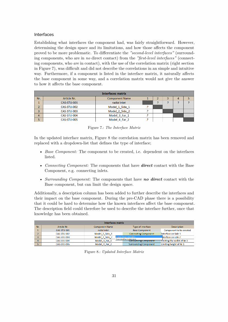
Interfaces
Establishing what interfaces the component had, was fairly straightforward. However,determining the design space and its limitations, and how those affects the componentproved to be more problematic. To differentiate the ”second-level interfaces” (surround-ing components, who are in no direct contact) from the ”first-level interfaces” (connect-ing components, who are in contact), with the use of the correlation matrix (right sectionin Figure 7), was difficult and did not describe the correlations in an simple and intuitiveway. Furthermore, if a component is listed in the interface matrix, it naturally affectsthe base component in some way, and a correlation matrix would not give the answerto how it affects the base component.
Figure 7.: The Interface Matrix
In the updated interface matrix, Figure 8 the correlation matrix has been removed andreplaced with a dropdown-list that defines the type of interface;
• Base Component: The component to be created, i.e. dependent on the interfaceslisted.
• Connecting Component: The components that have direct contact with the BaseComponent, e.g. connecting inlets.
• Surrounding Component: The components that have no direct contact with theBase component, but can limit the design space.
Additionally, a description column has been added to further describe the interfaces andtheir impact on the base component. During the pre-CAD phase there is a possibilitythat it could be hard to determine how the known interfaces affect the base component.The description field could therefore be used to describe the interface further, once thatknowledge has been obtained.
Figure 8.: Updated Interface Matrix
31
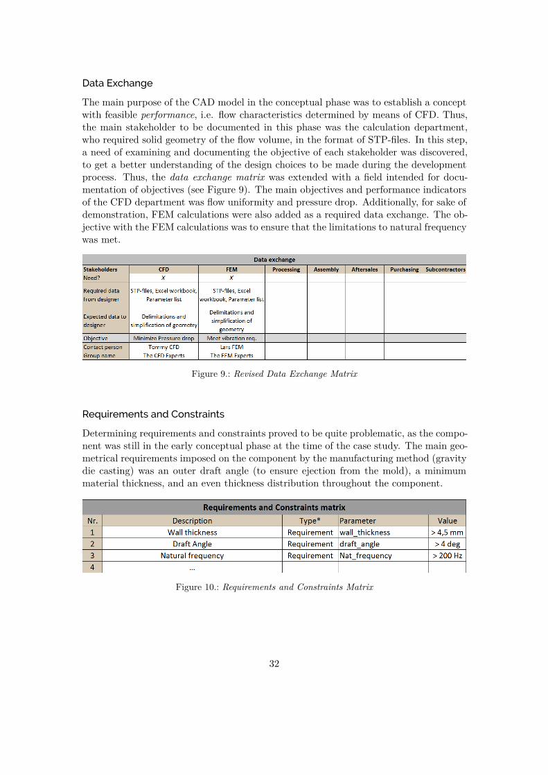
Data Exchange
The main purpose of the CAD model in the conceptual phase was to establish a conceptwith feasible performance, i.e. flow characteristics determined by means of CFD. Thus,the main stakeholder to be documented in this phase was the calculation department,who required solid geometry of the flow volume, in the format of STP-files. In this step,a need of examining and documenting the objective of each stakeholder was discovered,to get a better understanding of the design choices to be made during the developmentprocess. Thus, the data exchange matrix was extended with a field intended for docu-mentation of objectives (see Figure 9). The main objectives and performance indicatorsof the CFD department was flow uniformity and pressure drop. Additionally, for sake ofdemonstration, FEM calculations were also added as a required data exchange. The ob-jective with the FEM calculations was to ensure that the limitations to natural frequencywas met.
Figure 9.: Revised Data Exchange Matrix
Requirements and Constraints
Determining requirements and constraints proved to be quite problematic, as the compo-nent was still in the early conceptual phase at the time of the case study. The main geo-metrical requirements imposed on the component by the manufacturing method (gravitydie casting) was an outer draft angle (to ensure ejection from the mold), a minimummaterial thickness, and an even thickness distribution throughout the component.
Figure 10.: Requirements and Constraints Matrix
32
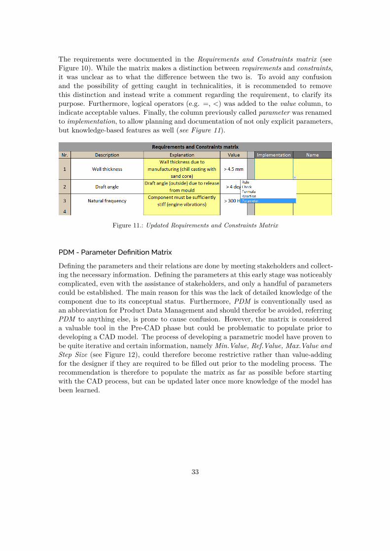
The requirements were documented in the Requirements and Constraints matrix (seeFigure 10). While the matrix makes a distinction between requirements and constraints,it was unclear as to what the difference between the two is. To avoid any confusionand the possibility of getting caught in technicalities, it is recommended to removethis distinction and instead write a comment regarding the requirement, to clarify itspurpose. Furthermore, logical operators (e.g. =, <) was added to the value column, toindicate acceptable values. Finally, the column previously called parameter was renamedto implementation, to allow planning and documentation of not only explicit parameters,but knowledge-based features as well (see Figure 11).
Figure 11.: Updated Requirements and Constraints Matrix
PDM - Parameter Definition Matrix
Defining the parameters and their relations are done by meeting stakeholders and collect-ing the necessary information. Defining the parameters at this early stage was noticeablycomplicated, even with the assistance of stakeholders, and only a handful of parameterscould be established. The main reason for this was the lack of detailed knowledge of thecomponent due to its conceptual status. Furthermore, PDM is conventionally used asan abbreviation for Product Data Management and should therefor be avoided, referringPDM to anything else, is prone to cause confusion. However, the matrix is considereda valuable tool in the Pre-CAD phase but could be problematic to populate prior todeveloping a CAD model. The process of developing a parametric model have proven tobe quite iterative and certain information, namely Min.Value, Ref.Value, Max.Value andStep Size (see Figure 12), could therefore become restrictive rather than value-addingfor the designer if they are required to be filled out prior to the modeling process. Therecommendation is therefore to populate the matrix as far as possible before startingwith the CAD process, but can be updated later once more knowledge of the model hasbeen learned.
33

Figure 12.: Parameter Definition Matrix
PRM - Parameter Relations Matrix
Associated with the Parameter Definition Matrix is the PRM - Parameter RelationsMatrix (see Figure 13), with the purpose of establishing and documenting relationshipsbetween parameters. According to the guideline it is critical in order to understand anddetermine the limitations of the model. However, the PRM does not help to clarify thelimitations of the model. The connection between the Parameter Definition Matrix andthe Parameter Relations Matrix is not perceived as intuitive, and thus do not solve theobjective it was designed for. In the Parameter Definition Matrix (see Figure 12) onlyexplicit parameters should be listed, i.e. characteristics, as described in subsection 2.2.3.
If there is a connection and relation between parameters, limitations on the dependentparameters (set in the PDM) cannot be determined, nor does the PRM aid in describingthe relations in a clear and systematic manner. For a parameter relation to exist, thereneeds to be a third component creating this relation, such as a formula or rule. Thethird component should be described in the Requirement and Constraint Matrix (seeFigure 11), thus making the original Parameter Relations Matrix redundant.
34

Figure 13.: Parameter Relations Matrix
4.3.2. Manufacturing Knowledge
In line with the scope of the thesis, steps were taken to investigate the possibility ofembedding the manufacturing knowledge to the model, and automating the process ofensuring fulfillment of the geometrical requirements, by use of knowledge-based engi-neering. However, due to the complex geometrical shape of the component, limitationsin the available tools in CATIA, and the goal of a generic solution, the task was notfeasible to carry out. The time investment required to develop such generic tool, appli-cable not only to the component in question but future components alike, would likelyovershadow the benefits provided and fall outside of the scope of the thesis. Instead,it was concluded more reasonable to, whenever possible, decompose and construct theCAD model in such a way that the geometrical requirements could not be violated, i.e.without the need of a synthesis/analysis loop (see subsection 2.2.3).
A crucial step in doing so was however to find the relevant knowledge associated withthose requirements and limitations, e.g. from existing design guidelines. As previouslydiscovered during interviews, the design guidelines are not utilized to its full poten-tial, likely due to the less than ideal format. As a solution, the design guidelines wereintegrated into the Excel-workbook, providing an interactive presentation of relevantknowledge for the component in question.
4.3.3. Parametric Modeling
The CAD modeling phase was performed by creating two identical models which weremorphed to one CAD model closer to the end of the modeling phase. The two CADmodels were designed in isolation to each other to determine the importance of modeldecomposition, structure and naming of features. After about a week the CAD modelswere exchanged, which showed the importance of a standardized naming and groupingof features, in order to convey the design intent. The design intent was fairly easy tofollow through both models, but it showed a difference in what was deemed importantand not.
35
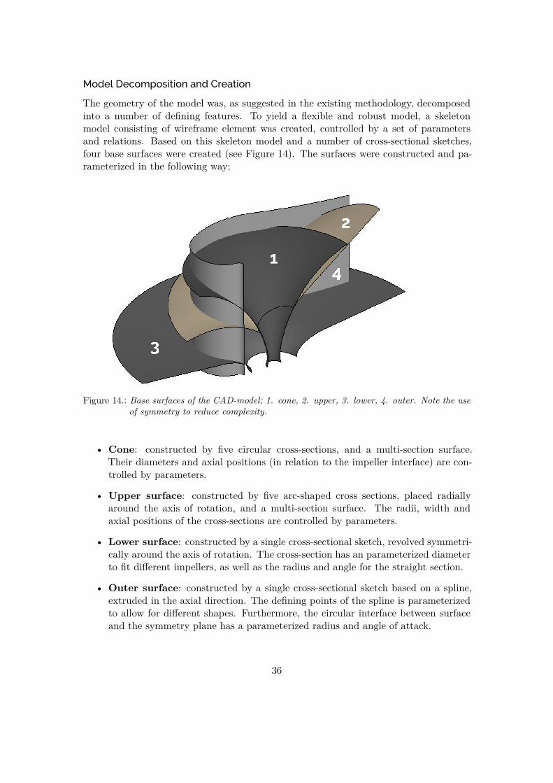
Model Decomposition and Creation
The geometry of the model was, as suggested in the existing methodology, decomposedinto a number of defining features. To yield a flexible and robust model, a skeletonmodel consisting of wireframe element was created, controlled by a set of parametersand relations. Based on this skeleton model and a number of cross-sectional sketches,four base surfaces were created (see Figure 14). The surfaces were constructed and pa-rameterized in the following way;
Figure 14.: Base surfaces of the CAD-model; 1. cone, 2. upper, 3. lower, 4. outer. Note the useof symmetry to reduce complexity.
• Cone: constructed by five circular cross-sections, and a multi-section surface.Their diameters and axial positions (in relation to the impeller interface) are con-trolled by parameters.
• Upper surface: constructed by five arc-shaped cross sections, placed radiallyaround the axis of rotation, and a multi-section surface. The radii, width andaxial positions of the cross-sections are controlled by parameters.
• Lower surface: constructed by a single cross-sectional sketch, revolved symmetri-cally around the axis of rotation. The cross-section has an parameterized diameterto fit different impellers, as well as the radius and angle for the straight section.
• Outer surface: constructed by a single cross-sectional sketch based on a spline,extruded in the axial direction. The defining points of the spline is parameterizedto allow for different shapes. Furthermore, the circular interface between surfaceand the symmetry plane has a parameterized radius and angle of attack.
36

The surfaces were split and trimmed, and radii were applied to any sharp edges. Fur-thermore, the model was mirrored around the symmetry plane, and an interface to thesurrounding air pipe was created. The progression of the surface model can be seen inFigure 15. Finally, a solid thickness was added to the surface model.
(a) before fillets (b) after fillets
(c) mirrored surface model (d) with inlet interface
Figure 15.: Progression of the surface model
Naming and grouping of features
Special care was taken to group and rename features in such way that the model wouldbe easy to understand and modify by future users. While the Resilient Modeling Method-ology [15], recommended and discussed in previous theses [28, 3, 25], features a completerecommendation on how to structure the model tree, it was discarded in favour of asimpler approach based on the existing start-up templates of Scania. The reason beingthat too controlling methods were one of the major qualms stated during the interviews(see section 4.1). Furthermore, the Resilient Modeling Methodology may be difficult toadapt to all different component types and groups at Scania.
37

(a) Overall tree structure (b) Detailed tree struc-ture
Figure 16.: Model tree structure
In line with the existing start-up templates, three top level geometrical sets were used;Imported Geometry, Reference Geometry and Construction Geometry. Each of the ge-ometrical sets were then populated by a number of sub-sets, one for each of the mainsurfaces created in the decomposition. The sub-sets, as well as any features and entitiescontained inside, were named after the surface or function in question. To further ensurea clear overview of the model and its features, all parameters were grouped (in parametersets) and named in the same fashion as for the geometrical sets. See Figure 16 (a) forthe overall structure of the model tree, and Figure 16 (b) for a suggestion of the detailedgrouping and naming of features and entities.
38

4.3.4. Model Quality
A minor inconvenience was discovered while defining the parameter ranges, and thus thedesign space in preparation of the DOE sequence, since the values had to be re-enteredfrom the Parameter Definition Matrix manually. While the actual parameters andranges used in the DOE might differ from those established in the Parameter DefinitionMatrix, the manual entry could give the user the impression of the Parameter DefinitionMatrix being a redundant and unnecessary step, and thus disregard it. To resolve theissue, an automatic retrieval function for the parameter values was implemented.
As presented in section 4.3.1, the difficulties in determining the parameter limits, andhence the design space, caused unreliable and unsatisfying model robustness, due to theunfeasible delimitation of the design space. The process of determining the design space,creating the model and evaluating its robustness was largely exploratory, and naturallyan iterative process. Thus, it was difficult, if not impossible, to finalize the model beforeevaluating its robustness. Instead, the evaluation phase should also be used for designspace exploration throughout the design process, i.e. aiding in properly delimiting thedesign space. An interpretation of this iterative process can be seen in Figure 17.
Figure 17.: A illustration of the iterative modeling process
39
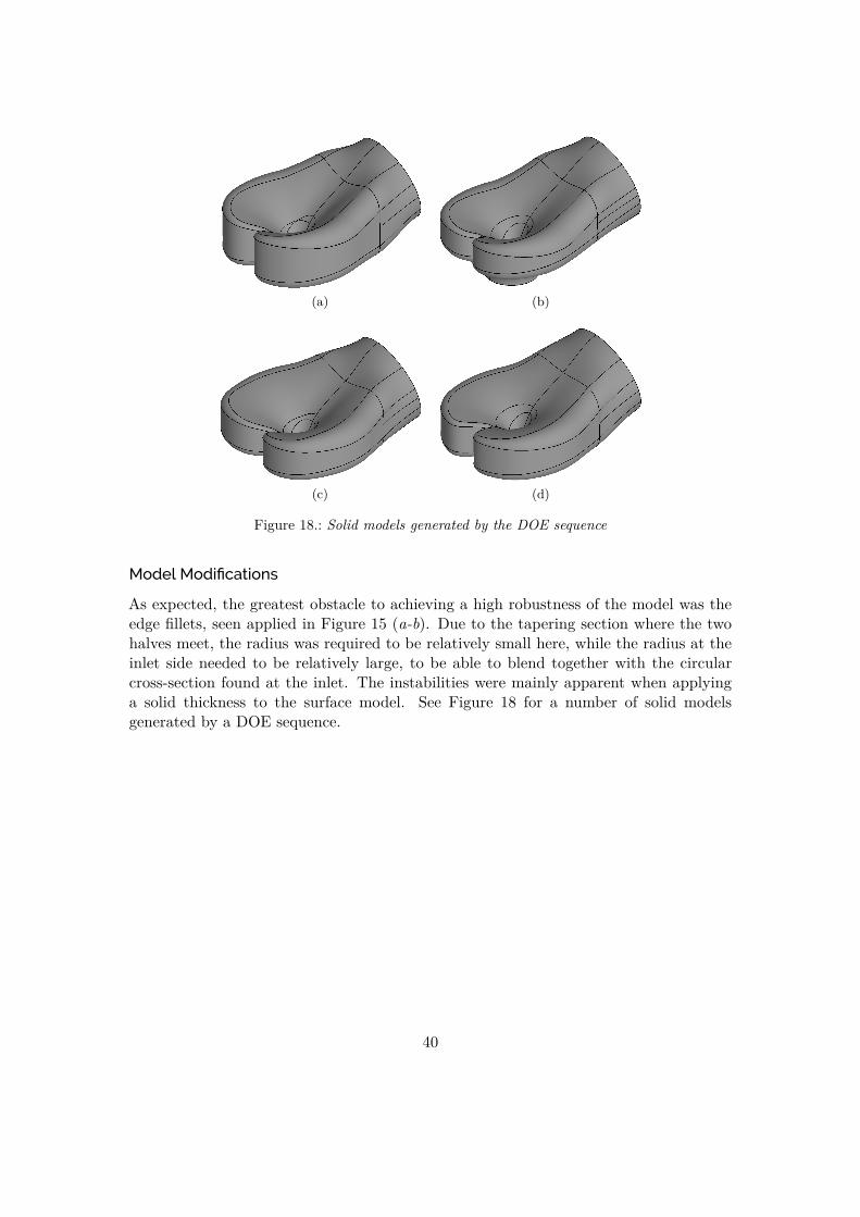
(a) (b)
(c) (d)
Figure 18.: Solid models generated by the DOE sequence
Model Modifications
As expected, the greatest obstacle to achieving a high robustness of the model was theedge fillets, seen applied in Figure 15 (a-b). Due to the tapering section where the twohalves meet, the radius was required to be relatively small here, while the radius at theinlet side needed to be relatively large, to be able to blend together with the circularcross-section found at the inlet. The instabilities were mainly apparent when applyinga solid thickness to the surface model. See Figure 18 for a number of solid modelsgenerated by a DOE sequence.
40

4.4. Final Methodology
With the findings from the case study, literature study, interviews and questionnaire,an updated methodology (see Figure 19) was developed to address shortcomings and im-prove upon previous methodologies. An Excel-workbook is intended to be used through-out the methodology to document and aid the process (see Figure 20).
Figure 19.: Final Methodology
4.4.1. Pre-CAD phase
The methodology is initiated with the pre-CAD phase, where information related to thecomponent is collected and assembled, to aid the upcoming model creation.
Figure 20.: Updated Overview of the Excel sheets
As in the existing product development process, the design engineer examines previousand similar components, suitable materials and manufacturing methods and what re-quirements they set on the geometry of the model. To efficiently exchange and collectinformation from various stakeholders, a formal stakeholder meeting is called to whichany affected party and discipline is invited.
The processes in the developed methodology, Figure 19, has corresponding sheets in theExcel workbook, Figure 20, in which the following topics are addressed;
• Information: basic information regarding the component such as componentname, article number and project is documented.
41

• Interfaces: any geometry directly connected or surrounding the model, and howthose may change in the future. The interfaces are documented in a specific inter-faces matrix.
• Data Exchange: any stakeholders from the various disciplines affected by thedevelopment process, and how the they assess the performance of the model (e.g.pressure drop for CFD, maximum stress for FEA). This gives the design engineera better understanding of how the model should be created and how the geometryneeds to be altered. Furthermore, the outputs required to the disciplines, such asparameter values, simplified geometries and file formats. This allows the designengineer to prepare the model for a fully-automated simulation driven design loop.
• Manufacturing: the manufacturing method, material and possible associationwith previous product types are selected, and based on the inputs a set of designguidelines are presented. The guidelines are used to assist in establishing require-ments and constraints in the following step.
• Requirements and constraints: that are set on the geometry by the variousdisciplines, and how they might be implemented into the CAD-model (includingby knowledgeware). These are documented using the requirements and constraintsmatrix. The documentation allows the design intent to be expressed for futureusers of the model.
• Parameters: here, all explicit parameters to be used in the model are collected,and their nominal, minimum and maximum values are established, with associatedstep sizes. The reason for collecting the parameters is to ease the upcoming robust-ness analysis, design exploration and optimization, by defining the desired designspace. As the design space may not be fully understood at this time, it is howeverfully acceptable and encouraged to revise these values at a later time.
The documentation of the pre-CAD phase is intended to be updated and revised duringthe course of the development process, when additional knowledge of the component andits model is acquired.
4.4.2. CAD Modeling and Robustness Evaluation
The modeling phase consists of an iterative loop in which a CAD model is created andmodified until the desired robustness is achieved. To achieve a robust and well-behavedmodel, it is recommended to create and control wireframe elements as far as possible, be-fore continuing to less stable surface elements (referenced to the wireframe elements) andfinally solid geometry. The model should be decomposed into simpler sub-geometries,e.g. defining surfaces or features, to maintain a flat hierarchical structure of featuredependencies.
42

The decomposition of the model, its parametrization and any requirements and con-straints defines the theoretical design space, i.e. the range of available designs possibleto achieve in theory by different combinations of the available parameters. However,in practice it may be difficult to successfully generate all of these designs. The modelsability to do so is defined as the robustness, and is assessed using Design of Experiments.Then, a number of parameter combinations, designs, are created to evenly sample allareas of the theoretical design space. The parameter combinations are used in the CADmodel, and the subsequent model generation can either succeed or fail. The amount ofsuccessful designs defines the actual design space, and the robustness can be visualizedas the ratio between successful and failed designs, i.e. how well the actual design spacecovers the theoretical.
Figure 21.: Design of Experiments with successful and failed designs
4.4.3. Exploration and Hand-off
This phase allows the design engineer to rapidly run CAE calculations without having toinvolve a dedicated CAE department. It has the purpose of helping the design engineerto gain knowledge of the physical properties related to the model, and to narrow downthe (actual) design space by removing unfeasible solutions. It may also reveal that asufficiently good solution is not found inside the available design space. Then, modifi-cations to the model such as parametrization and decomposition may be necessary, toextend and/or alter the design space. Thus, a high robustness value in the previous stepdoes neither indicate nor guarantee that a good solution could be found inside the designspace. The phase should be seen as an aid in determining the fundamental geometricalproperties of the product.
43

The calculations performed by the design engineer will most likely not yield as accurateresults as those of a dedicated CAE department, however, trends between performanceand geometry will likely be captured. The goal is not to remove the need for a dedicatedCAE group, but rather to reduce the number of iterations needed between the designengineer and the CAE group, yielding a more efficient design process, while allowing thedesign engineer to take decisions based on factual reasoning.
Figure 22.: Adaptation of the Design Space
When the design engineer has created a robust and flexible CAD model, with a welldelimited design space, e.g. ”Optimal Design Solutions” in Figure 22, the model isprepared for analysis by the dedicated CAE group. A number of context models willbe generated within the delimited design space and exported in file formats establishedduring the pre-CAD phase. The dedicated CAE group can then both validate the designsanalyzed by the design engineer, and further optimize the designs. Depending on thefeedback from the CAE group, the design may either be accepted or discarded. If thedesign is discarded, the pre-CAD phase has to be revised.
4.4.4. CAD Model Structure and Best Practices
The following general advice and best practice should be followed to create robust, flex-ible and parametric CAD models in CATIA V5;
• Renaming of features and entities: all features and entities created by the usershould be renamed to describe its intent, to the extent practically possible. Thus,renaming entities and features in merely a sequential way (e.g. Fillet.1, Fillet.2)should be strongly discouraged, as it does not bring any value to the understandingof a model and its design intent.
44

• Organize the model tree structure: according to the pre-existing geometricalsets and solid bodies of the start-up templates. Any additional geometrical setsshould be named descriptively and be related to one feature or aspect of the model.Strive to keep the tree structure tidy and understandable.
• Sketch usage: all sketches used should be of type positioned sketch, and allcontained entities in the sketch should be fully constrained to the local sketch axissystem. This allows the sketch with its entities to be moved and/or reused in otherpositions, regardless of the global axis system, without altering or breaking anyinternal constraints inside the sketch.
• No references to boundary representations: such as edges and faces of asolid. As these elements are less stable than e.g. wireframe elements, they shouldonly be referenced if absolutely needed, as in the case of dress-up features, e.g.fillets and chamfers. Always strive to use a dedicated skeleton model consisting ofwireframe elements, to control the basic structure of the geometry.
• Flat hierarchical structure of feature dependencies, i.e. reduce ”parent-child”relationships in the model, to avoid a ”domino-effect” should a feature fail togenerate properly. This could partly be achieved by using a skeleton model, i.e. acollection of datum features of planes and wireframe elements. Furthermore, it isbeneficial to decompose the model into simpler geometrical elements, e.g. surfacesor solids.
45
5. Discussion
In the following chapter, the results and the methodology of the thesis will be discussed.
5.1. Discussion of Results
The following section is divided into the four main topics, covering the results of thethesis.
5.1.1. Information Collection
Interviews revealed a lack of explicit documentation of knowledge related to the com-ponent, potentially causing inefficiencies in the design- and model creation process. Asolution is proposed in previous and current methodologies, by use of a Excel workbookto document such information. While this allows the documentation to be collectedin a common, dedicated location, the case study showed a non-streamlined integrationinto the design process. Thus, the method may be perceived as yet another counter-intuitive and disintegrated software, a common complaint expressed during the inter-views. As suggested by the literature, it would be better to integrate such moments intothe PLM-system, resulting in a seamless process between modeling, documentation andknowledge-reuse. Pending such integration, the Excel workbook acts as a temporarymethod to show potential areas of improvement, but should not be seen as a permanentsolution.
46

5.1.2. Manufacturing Knowledge
As discovered during the case study, it is difficult to develop a universal and genericguideline for how manufacturing knowledge should be embedded to a CAD model. Whileknowledge-based functions could rather easily be developed and utilized to embed knowl-edge related to product characteristics, the same can not be said regarding productproperties, requiring processing with separate analysis tools. However, as evident frominterviews, manufacturing knowledge and constraints are commonly considered by thedesign engineer early in the development process, reducing the benefits of automating thereuse of such knowledge. As also discovered during the case study, there are possibilitiesand benefits to be made by utilizing and reusing manufacturing knowledge without em-bedding it into the CAD model specifically. As presented in the developed methodology,existing knowledge in the form of design guidelines could be better utilized by interac-tively presenting relevant and up-to-date knowledge. Furthermore, the design guidelines,currently stored in Excel workbooks, should migrate to a more suitable storage format.The guidelines are technically a database of knowledge and should therefore be storedin a database, such as SQL or Access. This would ease the integration with the designprocess and make the design guidelines less cumbersome to update, not to mention thepossibility to share the knowledge between other disciplines.
5.1.3. Parametric Modeling
While previous work has demonstrated parametric modeling and knowledge-based engi-neering, most users does in fact not utilize such tools, as evident from interviews and thequestionnaire. This would indicate a lack of impact and usage of previous methodologies,which is likely a result of several factors.
First and foremost, there is a lack of educational material and training on the subject,reserving such training to curious users doing so in spare time, which is often in shortsupply. Thus, it would be essential to allocate sufficient time not only for the trainingand up-keeping of knowledge, but for parametric modeling in the day-to-day business.This naturally needs to origin from the management side of business, which needs torealize how a larger initial time expenditure can be motivated by long-term benefits. Asfor the training, it would be a natural development of introducing the subject of paramet-ric modeling and knowledge-based engineering during initial CAD courses, which wouldlikely develop a natural mind-set and modeling practice among the design engineers.
47

Secondly, as discussed in the theoretical framework, the tools used in the methodol-ogy would probably see a larger usage if they were more intuitive and streamlined intothe development process, which would be possible using existing tools, namely a PLM-system. Furthermore, the usage of the methodology would likely benefit from a changeof presentation. The methodology should be introduced as a tool, which would aid andbenefit the designer in its work rather than being pushed as a demand for conductingsimulation-driven design. By promoting usage throughout the whole design process, abroader utilization may be seen, thus ensuring the usage of the methodology.
While demonstrating possibilities and benefits of complex modeling techniques is helpfulin raising awareness and interest, there is a risk of further ”raising the bar”, wideningthe gap between user practice and theory. The work should focus on enabling the usersto apply theory in practice, reaching a higher and uniform model quality. Thus, it isrecommended to focus on the basic elements of parametric modeling, which is why thisthesis has not been focused on adding complexity to the existing methodology.
5.1.4. Model Quality
As discovered during the interviews, current CAD models are of uneven quality, makingcollaboration difficult as the design intent is not clearly conveyed. As reinforced by thetheoretical framework, a way of resolving the issue would be to introduce a modelingstandard specifically targeted at improving and assuring 3D CAD-model quality.
Interestingly, as evident from the questionnaire study, most users follow a methodologywhen creating their CAD models, group and rename features based on intent, but yetfind other users models to be difficult to both understand and modify. This stresses thedifferences in perception of how the model should be organized and constructed to allowthe intent to be easily understood by others, which is also shown from the interviews.Furthermore, it can be concluded that current methodologies fails in aiding the usersto create models with a clear modeling strategy (by a standardized modeling practice),causing unnecessary time spent on modifying models of other users.
As for naming of individual features and entities in the CAD model, it is likely of higherimportance that the designer in fact does rename them, rather that what they renamethem to. This as it forces the designer to reflect on how the design intent is conveyed, byusing descriptive naming. Furthermore, as it would be difficult to create and enforce astrict naming convention for all possible product types and scenarios, it would be betterto focus on common structures.
48

Ensuring compliance of the model structure to the standard would both be recommendedand rather effortless, by implementing new rules in the existing model quality assurancesystem (Q-Checker), and most importantly, to enforce the rules of this system. Possiblepractices on doing so might be to flag the model for future check-up, and/or prohibitingthe model to be checked into the PDM/PLM system, if any discrepancies are detected.As a temporary solution while such integration is made, it would be recommended toimplement a peer-review process of 3D-CAD models, much like the current approvalprocess of 2D drawings. As an aid in such review process, checklists inspired by thoseof Resilient Modeling Strategy [15] could be used. This would force the design engineerto take time and clean up their model as it evolves and progresses, thus ”sanitizing” themodel regularly. A creative ”trial-and-error” process of creating the model would stillbe possible, as opposed to fully planning the structure and naming beforehand, whichwould probably be perceived as inhibiting to the designer.
5.1.5. Environmental and Ethical Impact
As shown by theory, the introduction of a parametric modeling methodology would yielda more efficient product development process. While this is highly beneficial for Scania,as less expenditure of resources is necessary and better products can be achieved, it isalso highly beneficial for the society as a whole. The reduced expenditure of resourceswill itself lead to reduced environmental impact, and above all, better products in theautomotive industry equates to lower fuel consumption and emissions. Thus, the auto-motive industry will continue to work towards higher sustainability, and provide a vastamount of jobs worldwide. Better products would also contribute to increased safety forall road-users. Furthermore, as the methodology would likely assist in improving theinformation exchange and allow for factual reasoning in the development process, designengineers and other users would potentially experience less stress, and a better workingenvironment.
49

5.2. Discussion of Methodology
The following section is divided into the two main topics, covering the methodology ofthe thesis.
5.2.1. Case Study
As discovered early during the data collection, the main reason why parametric mod-eling has not been used to any large extent at Scania is not due to any major flawsor shortcomings of current methodologies. Thus, the case study showed to be of lessimportance to the findings of the thesis than initially thought, and the scope of thethesis shifted somewhat from developing a new methodology to identifying the obstaclesof implementing the already existing ones. Nevertheless, it was considered very advan-tageous to follow the documentation currently available to the design engineers of Scania.
Creating a robust and flexible CAD-model of the radial inlet was highly challenging,partly due to the complex and organic shape of the component, and most importantly,due to the low understanding of the design space as the component was in the concep-tual phase of the product development process. As expected, the greatest obstacle toovercome in creating a robust CAD-model was the dress-up features, in this case filletsand drafts. Steps were taken to replace these by use of surface modeling techniques, butwithout any major improvements in robustness. While these features are undeniablyimportant to yield a realistic and manufacturable representation of the component, theconceptual state of the component put a larger focus on the performance aspects (i.e.flow characteristics), where they are of less importance. However, the manufacturingrequirements were considered during all parts of the model creation process, and a planwas created for how to manually implement these into the model when the design spacehas been properly delimited.
5.2.2. Data Collection
The conducted interviews provided a clear and valuable insight into the actual practicesof Scania, from experienced and inexperienced engineers alike. The semi-structured for-mat was especially helpful, since it allowed the interviewees to elaborate and introducesubjects previously not thought of. As the interviewees were fairly consistent in opinion,despite their difference in experience, it was concluded unnecessary to conduct a largeramount of interviews.
In addition to the interviews, a questionnaire was utilized to collect quantitative datafrom a larger audience. The response rate of the questionnaire may be seen as mediocreat first sight, but is however very similar to that of previous theses targeting the sameaudience, and may therefore be expected. Furthermore, the results from the question-naire was not used in any decision-making processes, rather than as a validation andcomplement to the interviews and the empirical findings.
50

6. Conclusion
6.1. Research Question 1
What product related information and knowledge should be connected to a parametricCAD model to ensure and improve manufacturability?
Manufacturing knowledge related to product properties1, i.e. parameters not controlleddirectly by the design engineer, is difficult to implement into the CAD-environment ina convenient way, since a synthesis/analysis loop is required to assess the impacts in aseparate analysis tool. Furthermore, as each model has unique geometrical conditionswhich has to be accounted for, this process might be difficult to automate. Thus, onlyknowledge related to consistently defined product characteristics, i.e. param-eters directly controlled, may be included in the CAD model.
Due to the complexity in embedding and automating the knowledge related to productproperties, it is better if the design engineer is presented with applicable knowledge in aclear way, to aid in applying such knowledge to the model. Here, the use of interactivedesign guidelines is recommended.
6.2. Research Question 2
What is the recommended practice on implementing a multidisciplinary, parametric CADmodeling approach, to give good conditions for widespread usage?
While parametric modeling has considerable potential in enabling design automation,it is crucial, and most beneficial in terms of automation efficiency, to start with thefundamentals, namely achieving a uniform modeling practice by the use of standards.Thus, the quality of the CAD models can be ensured, and prerequisites for further designautomation are fulfilled.
To introduce parametric modeling as a natural and integrated step of the developmentprocess, proper training material and internal courses are essential. While itwould be beneficial to have certain experts in the area, either by a dedicated work groupor distributed among the departments, it is important that the topic is introduced to alldesign engineers, preferably in the initial CAD courses.
1see subsection 2.2.3 (page 9) for an explanation of the terminology by Gembarski et al. [16]
51

As for the tools used in parametric modeling, it is important to fully utilize exist-ing PDM/PLM-solutions to enable an integrated, intuitive and streamlined way ofworking. Separate tools such as Excel workbooks are helpful in performing specific tasksand demonstrating possibilities without any additional costs, but they can however beperceived as bothersome to use.
A large organization requires a large scale implementation, with involvement from alllevels of the organization, to have an impact. As it is difficult to quantify the benefits ofsuch implementation, and thus to justify the expenses, it is important to keep a holisticperspective and consider long-term benefits and possibilities.
6.3. Research Question 3
How could a product development process benefit from implementing a parametric CADmodeling approach?
In the short term, the introduction of a standardized modeling practice and model qual-ity assurance would lead to a more uniform model quality, and thus the design intentwould be better kept and conveyed. This would lead to easier to understand models,and ease the collaboration between users. In the long term, the standardized modelingpractice would allow design automation and the widespread use of multi-disciplinary de-sign optimization, reducing development time and thus cost, while being able to findbetter designs through design space exploration and optimization.
Overall, implementing a parametric CAD modeling approach would yield shorter lead-times, allowing for faster adaptation to changing conditions, and reduced develop-ment expenditures.
52

7. Further Studies
To allow for the successful integration of parametric modeling into the development pro-cess at Scania, it is as previously discussed necessary to create proper training materialin the form of courses and/or tutorials. An interesting area to investigate would be howto form such training material, in an efficient way. Furthermore, as discovered duringthe thesis, it would be essential to research upon how the methodology would be practi-cally implemented into existing PDM/PLM-systems.
As an addition to the introduction of basic, part-level parametric modeling, it would bea natural progression to examine the usage of parametric, product-level models. Sug-gested areas to investigate would be how models interact, and how they can be linkedin a robust manner.
To allow for the future usage of multidisciplinary optimization, it would be of interestto examine how context models can be used in an efficient manner. Important researchquestions would be if one master model should be used from which all discipline-specificmodels are generated, or if each discipline should have an independent parametric modelfor their needs.
53
Bibliography
[1] Kristian Amadori. ”Geometry based design automation: Applied to aircraft mod-elling and optimization”. PhD thesis. Linköping University Electronic Press, 2012(cited on pages 3, 10).
[2] Jiju Antony. Design of experiments for engineers and scientists. Elsevier, 2014(cited on page 14).
[3] Marcus Blomberg. ”Development of a parameterization methodology to aid sim-ulation driven design; using intake ports of a heavy-duty diesel engine as a casestudy”. Master’s thesis. Linköping University, 2015 (cited on pages 4, 19–21, 24,37).
[4] Yannick Bodein, Bertrand Rose, and Emmanual Caillaud. ”Improving CAD per-formance: a decisional model for knowledgeware implementation”. In: DS 58-8:Proceedings of ICED 09, the 17th International Conference on Engineering De-sign, Vol. 8, Design Information and Knowledge, Palo Alto, CA, USA, 24.-27.08.2009. 2009 (cited on page 7).
[5] Yannick Bodein, Bertrand Rose, and Emmanuel Caillaud. ”A roadmap for para-metric CAD efficiency in the automotive industry”. In: Computer-Aided Design45.10 (2013), pages 1198–1214 (cited on pages 11–13).
[6] Yannick Bodein, Bertrand Rose, and Emmanuel Caillaud. ”Explicit reference mod-eling methodology in parametric CAD system”. In: Computers in Industry 65.1(2014), pages 136–147 (cited on pages 4, 20).
[7] Jorge D Camba, Manuel Contero, and Pedro Company. ”Parametric CAD mod-eling: An analysis of strategies for design reusability”. In: Computer-Aided Design74 (2016), pages 18–31 (cited on page 3).
[8] Marco Cavazzuti. Optimization methods: from theory to design. Springer Science& Business Media, 2012 (cited on pages 13, 14).
[9] Mikael Cederfeldt. ”Planning design automation: A structured method and sup-porting tools”. PhD thesis. Department of Product and Production Development,Chalmers University of Technology, 2007 (cited on pages 5, 6, 10).
[10] Mikael Cederfeldt and Staffan Sunnersjö. ”Solid modelling with dimensional andtopological variability”. In: DS 31: Proceedings of ICED 03, the 14th InternationalConference on Engineering Design, Stockholm. 2003 (cited on page 3).
54

[11] Angelo Corallo, Robert Laubacher, Alessandro Margherita, and Giuseppe Turrisi.”Enhancing product development through knowledge-based engineering (KBE) Acase study in the aerospace industry”. In: Journal of Manufacturing TechnologyManagement 20.8 (2009), pages 1070–1083 (cited on page 9).
[12] Richard Curran, Wim JC Verhagen, Michel JL Van Tooren, and Ton H van derLaan. ”A multidisciplinary implementation methodology for knowledge based engi-neering: KNOMAD”. In: Expert Systems with Applications 37.11 (2010), pages 7336–7350 (cited on page 8).
[13] Rosalind Edwards and Janet Holland. What is qualitative interviewing? Blooms-bury Academic, 2013 (cited on page 23).
[14] Filipe Ferreira, José Faria, Américo Azevedo, and Ana Luisa Marques. ”Productlifecycle management in knowledge intensive collaborative environments: An ap-plication to automotive industry”. In: International Journal of Information Man-agement 37.1 (2017), pages 1474–1487 (cited on page 10).
[15] Richard Gebhard. ”A Resilient Modeling Strategy”. Technical Presentation. 2013.url: https://community.plm.automation.siemens.com/siemensplm/attachments/siemensplm/solid- edge- tkb/159/1/122%20-%20A%20Resilient%20Modeling%20Strategy%20%20-%20Richard%20Gebhard.pdf (visited on 01/31/2017) (citedon pages 4, 5, 20, 37, 49).
[16] PC Gembarski, B Sauthoff, T Brockmöller, and R Lachmayer. ”Operationalizationof manufacturing restrictions for CAD and KBE-systems”. In: DS 84: Proceedingsof the DESIGN 2016 14th International Design Conference. 2016 (cited on pages 9,51).
[17] Karl-Heinrich Grote and Erik K Antonsson. Springer Handbook of MechanicalEngineering. Springer Science & Business Media, 2009 (cited on page 16).
[25] Martin Jansson and Anton Wiberg. ”Development of parametric CAD models toaid simulation driven design for multiple disciplines”. Master’s thesis. LinköpingUniversity, 2016 (cited on pages 19–21, 24, 37).
[26] Gianfranco La Rocca. ”Knowledge based engineering: Between AI and CAD. Re-view of a language based technology to support engineering design”. In: Advancedengineering informatics 26.2 (2012), pages 159–179 (cited on pages 6, 7).
[27] Jonas Lundin and Mats Sköldebrand. ”KBE in Product Development at Scania;An investigation of the potential in CATIA Knowledgeware”. Master’s thesis. KTHRoyal Institute of Technology, 2008 (cited on page 19).
[28] ViChi Luu. ”Methodology development for parametric CAD modeling in CATIAV5 to aid simulation driven design using turbine volute as a case study”. Master’sthesis. Linköping University, 2015 (cited on pages 4, 10, 19–21, 24, 27, 29, 37).
[29] Joaquim RRA Martins and Andrew B Lambe. ”Multidisciplinary design optimiza-tion: a survey of architectures”. In: AIAA journal 51.9 (2013), pages 2049–2075(cited on page 13).
55

[30] Justinas Peciura. ”Swirling Airflow Influence on Turbocharger Compressor Perfor-mance.” Master’s thesis. 2015 (cited on page 25).
[31] Tommy Pham. ”Development of parametric CAD models with multi-disciplines toaid simulations”. Master’s thesis. Linköping University, 2016 (cited on pages 19,24).
[32] Martinez-Botas Ricardo, Pesiridis Apostolos, and MingYang Yang. ”Overview ofboosting options for future downsized engines”. In: Science China TechnologicalSciences 54.2 (2011), pages 318–331 (cited on page 24).
[33] Bahr Rogerio and Weller Tiago. Automotive Industry CAD System Automationthrough Knowledge Based Engineering (KBE) Case Study. Technical report. SAETechnical Paper, Oct. 2016 (cited on page 7).
[34] Vahid Salehi-Douzloo. ”An Integrated Approach to Parametric Associative Designfor Powertrain Components in the Automotive Industry”. PhD thesis. Universityof Bath, 2011 (cited on pages 4, 10, 20).
[35] QA Siddiqui, Neil D Burns, and Chris J Backhouse. ”Implementing product datamanagement the first time”. In: International Journal of Computer Integrated Man-ufacturing 17.6 (2004), pages 520–533 (cited on pages 10, 11).
[36] Wojciech Skarka. ”Application of MOKA methodology in generative model cre-ation using CATIA”. In: Engineering Applications of Artificial Intelligence 20.5(2007), pages 677–690 (cited on page 8).
[37] Jaroslaw Sobieszczanski-Sobieski and Raphael T Haftka. ”Multidisciplinary aerosp-ace design optimization: survey of recent developments”. In: Structural optimization14.1 (1997), pages 1–23 (cited on page 13).
[38] Svenska Gjuteriföreningen, Swerea SWECAST AB, and Sveriges GjuteritekniskaFörening. Gjuteriteknisk Handbok. url: http://www.gjuterihandboken.se/ (visitedon 02/23/2017) (cited on page 16).
[39] Mehdi Tarkian. ”Design Automation for Multidisciplinary Optimization: A HighLevel CAD Template Approach”. PhD thesis. Linköping University ElectronicPress, 2012 (cited on pages 3, 10).
[40] RA Van den Braembussche. Flow and loss mechanisms in volutes of centrifugalpumps. Technical report. DTIC Document, 2006 (cited on page 25).
[41] Wim JC Verhagen, Pablo Bermell-Garcia, Reinier EC van Dijk, and Richard Cur-ran. ”A critical review of Knowledge-Based Engineering: An identification of re-search challenges”. In: Advanced Engineering Informatics 26.1 (2012), pages 5–15(cited on pages 6–8).
56

Interviews
[18] Interviewee 1. Interview with Design Engineer at Scania CV AB (NMGK), Södertälje.Feb. 23, 2017 (cited on pages 26–28).
[19] Interviewee 2. Interview with Design Engineer at Scania CV AB (NMGK), Södertälje.Feb. 23, 2017 (cited on pages 26–28).
[20] Interviewee 3. Interview with Design Engineer at Scania CV AB (NMGK), Södertälje.Feb. 27, 2017 (cited on pages 26–28).
[21] Interviewee 4. Interview with Design Engineer at Scania CV AB (NMGK), Södertälje.Feb. 28, 2017 (cited on pages 26–28).
[22] Interviewee 5. Interview with Design Engineer at Scania CV AB (NMGK), Södertälje.Mar. 2, 2017 (cited on pages 27, 28).
[23] Interviewee 6. Interview with Design Engineer at Scania CV AB (NMGV), Södertälje.Mar. 3, 2017 (cited on page 27).
[24] Interviewee 7. Interview with Design Engineer at Scania CV AB (NMGK), Södertälje.Mar. 10, 2017 (cited on pages 26–28).
57

Appendix A.
Interview Guide (Design Engineers)
Parametric Modeling
1. How long have you been working with CAD, and in what system?
2. Would you say that the CATIA modeling process (at Scania) is repetitive andmonotone?
3. Are you aware of parametric modeling?a) If yes: What is your opinion on it?
4. Do you use parametric modeling in your daily work?a) If yes: explain howb) If no: explain why
5. What are the drawbacks (if any) of parametric modeling according to you?
6. Has there been any attempts (from management or within the group) to implementthe results of previous theses, or parametric modeling in general? Explain.
Information Collection
7. What are the different disciplines/groups that could affect the geometry of yourmodel?
8. Is information and demands, on the geometry, from other disciplines easily avail-able?
9. What is the process of collecting this information and/or demands from otherdisciplines?
Manufacturing
10. From your experience; Does the involvement of a supplier lead to changes in thedesign and why?
58

11. When in the design process are manufacturing aspects considered?
12. If you could decide, what would a optimal design process look like?
Parametric Modeling in Practice
13. Which products are you working on?
14. How and when do you think you would have use of parametric modeling? Onwhich products, in which situations, to what extent?
15. How do you think it would be beneficial to parameterize the model of the radialinlet?
59
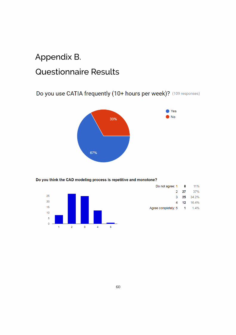
Appendix B.
Questionnaire Results
60
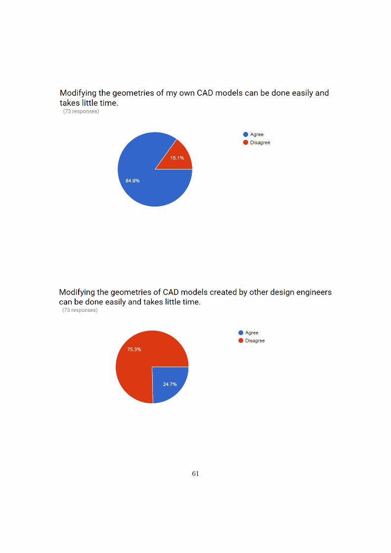
61

62

63

64

65

Upphovsrätt
Detta dokument hålls tillgängligt på Internet — eller dess framtida ersättare — under 25 år frånpubliceringsdatum under förutsättning att inga extraordinära omständigheter uppstår.
Tillgång till dokumentet innebär tillstånd för var och en att läsa, ladda ner, skriva ut enstaka kopiorför enskilt bruk och att använda det oförändrat för ickekommersiell forskning och för undervisning.Överföring av upphovsrätten vid en senare tidpunkt kan inte upphäva detta tillstånd. All annan an-vändning av dokumentet kräver upphovsmannens medgivande. För att garantera äktheten, säkerhetenoch tillgängligheten finns det lösningar av teknisk och administrativ art.
Upphovsmannens ideella rätt innefattar rätt att bli nämnd som upphovsman i den omfattning som godsed kräver vid användning av dokumentet på ovan beskrivna sätt samt skydd mot att dokumentet änd-ras eller presenteras i sådan form eller i sådant sammanhang som är kränkande för upphovsmannenslitterära eller konstnärliga anseende eller egenart.
För ytterligare information om Linköping University Electronic Press se förlagets hemsida:http://www.ep.liu.se/
Copyright
The publishers will keep this document online on the Internet — or its possible replacement — for aperiod of 25 years from the date of publication barring exceptional circumstances.
The online availability of the document implies a permanent permission for anyone to read, to down-load, to print out single copies for his/her own use and to use it unchanged for any non-commercialresearch and educational purpose. Subsequent transfers of copyright cannot revoke this permission.All other uses of the document are conditional on the consent of the copyright owner. The publisherhas taken technical and administrative measures to assure authenticity, security and accessibility.
According to intellectual property law the author has the right to be mentioned when his/her work isaccessed as described above and to be protected against infringement.
For additional information about the Linköping University Electronic Press and its procedures forpublication and for assurance of document integrity, please refer to its www home page:http://www.ep.liu.se/
c� Mattias Lokgård and Andreas Grandicki