Индустриальные редукторы серии Paramax SFC Cooling Tower Drives Sumitomo


Complete Drive System Solutions
PARAMAX 9000 Series Conveyor Drives
Motor Variety of motor options
Coupling Flex or fluid coupling and guard
Baseplate Swing base, common welded steel baseplate
PARAMAX Offers the Toughest Gear Drives Available to
Meet the Harsh Demands of Mining Conveyor Drives.
The mining industry places heavy demands on power transmission drives. Tough operating conditions, high shock loads, dirt, moisture, and acidic environments take a large toll on the equipment that keeps your operation moving.
Torque range : Number of sizes : Reduction Ratio : Shaft Arrangement : Housing: Flippable Design
20kN・m ~122kN・m 10 sizes 14~31.5 Right Angle Shaft Split housing / Cast iron
Your power transmission drives must be tough, reliable, and efficient. Strength, power, and performance are not optional. For these reasons, you rely on Sumitomo Drive Technologies for your power transmission products.
Recognized as a global leader in power transmission knowledge and innovation, the unmatched strength of our product range, application experience, and global presence establishes Sumitomo as the premiere power transmission solution provider.
With installations in more than 35 countries worldwide, Sumitomo Products are the preferred choice by some of the largest companies in the mining industry. Whatever your mining application, we understand the unique challenges you face, and we have reliable, durable solutions that deliver the lowest possible life- cycle cost and the highest level of performance.
R


General InformationNomenclature
Standard Specifications
Recommended Lubricant
Service Factor
General Information
P H D 9075 R 3 C RR K F 25 - -
Item
Lubrication Method
Reducer
Ambient Conditions
Installation
Painting
Surface preparation : Shot blast after wash before mashining Inside paint : UNI GROUND PTC primer is sprayed once Outside paint : For primer coating, UNI GROUND PTC primer is sprayed once.
For final coating, NEORON #2000 is sprayed once. Paint color : Donau Blue (equivalent Munsell color : 6.5PB 3.6/8.2)
Gear Type
Oil bath lubrication
Lubricant
Involute external gear
Ambient Temperature -10 C ~ 40 C
Ambient Humidity Under 85%
Elevation Less than 1,000 meters above sea level
Atmosphere Well ventilated location, free of corrosive and explosive gases, vapor
Refer to Page 6 for recommended lubricants.
Output Speed Ambient Temperature
Over 100 r/min
Under 100 r/min
ISO VG68 AGMA 2EP
ISO VG100 AGMA 3EP
-10 C to 15 C
ISO VG150 AGMA 4EP
ISO VG220 AGMA 5EP
0 C to 30 C
ISO VG220 AGMA 5EP
ISO VG320 AGMA 6EP
10 C to 50 C
* * *
*
* Kinetic Viscosity (mm /s) at ISO 40 C 2
* *
-3 0
-3 3
①
① P : PARAMAX DRIVE
② Mounting
③ Gear Box Case
H : Horizontal Mounting
D : Split Case
R
9055, 9060, 9065, 9070, 9075 9080, 9085, 9090, 9095, 9100
14, 16, 18, 20, 22.4, 25, 28, 31.5
: Right Angle Shaft
Blank : Solid Shaft T : Hollow Shaft Shrink Disk Type K : Hollow Shaft Key Type
F : With Cooling Fan B : With Backstop FB : With Cooling Fan and Backstop
④ Gear Box Size
⑤ Assembly Type
2 or 3 ⑥ Number of Stages
⑦ ApplicationC : Conveyor Drives
⑧ Shaft Arrangement
⑨ Slow Speed Shaft
⑩ Optional Accessories
⑪ Nominal Reduction Ratio IN
② ③ ④ ⑤ ⑥ ⑦ ⑧ ⑨ ⑩ ⑪
65
RL RR RB LR LL LB
View from TOP
Solid Shaft Shrink Disk Type Key Type
Driven Machine Operating Hours (hours/day) 3 hrs 10 hrs 24 hrs
CONVEYORS Uniformly load or fed
Heavy load Not uniformly fed
Reciprocating or shaker
1.00
1.00
1.50
1.00
1.25
1.75
1.25
1.50
2.00

Selection Guideline Selection Guideline
87
Yes
No
Yes
No
No
No
No
Yes
Yes
Yes No
Yes
Determine the service factor
Calculate equivalenttransmission power PE
Determine Nomenclature
Determine page numberindicating Dimension Table.
Determine Temperature correction factor
Ambient condition
Determine Size PE PM
Check Thermal PowerPT0 × Ta × Th PM
Standard Specifications Page 5
PA: Actual transmission power or motor SF : Service factor : Page 6 PE : Equivalent transmission power
PM : Mechanical power rating Double Reduction : Page 9 Triple Reduction : Page 11
PE = PA x SF
• Refer to the bottom row of mechanical power rating table for page number of dimensional drawing.
• Select shaft arrangement from "Standard Shaft Arrangement Configuration” in the dimension tables.• Determine nomenclature.
Ta : Temperature correction factorTh : Altitude factor
PT0 : Thermal power rating
Is overhung loadapplied to the high
speed shaft?
Is overhung loadapplied to the slow speed
shaft?
Calculate equivalent radial load FrE
Check overhung loadFr E Fr A
Complete selection
Calculate equivalent radial load FrEand calculate equivalent thrust load FxE
Check overhung load
1 Fr E
Fr A
Fx E
Fx A
Consult us for large overhung load.
Consult us for forced cooling systemsuch as oil cooler.
Is overhung load radialload only?
Calculate equivalent radial load Fr E and equivalent thrust load Fx E at peak load.
Refer to the page 13 for Fr A , and Fx A values.
Fr E : Equivalent radial load = Peak radial load Fr Fx E : Equivalent axial load = Peak thrust load Fx Fr A : Allowable radial load Fx A : Allowable axial load
Conditions Selected item
P.6 Service Factor
P.5 Nomenclature
Motor power High speed shaft speed
Load Condition Type of load, Operating hours Determine service factor SF = 1.50
Calculate equivalent transmission power PE = 132 1.50 = 198 kW
Slow speed shaft speed Reduction ratio
Select nominal reduction ratio
1800/65 =27.6 27.6 iN = 28
Determine size Size 9070, Nominal Reduction Ratio 28 Mechanical power rating P = 251 kW
PE P OK
Ambient Temperature
Temperature correction factor without fan Ta Ta = 0.70 Altitude factor Th = 1.0
Thermal rating without fan PT P T = 88kW P T T h T a
T h T a
= 61.6<132 = PM OUT
Temperature correction factor with fan Ta Ta = 0.73 Thermal rating with fan PT P T = 256kW
P T = 186 >132 = PM OK With fan
Check overhung load
Radial load position and direction Peark radial load Fr Peark thrust load Fx Equivalent radial load Fr E = 10.6 Allowable radial load 54.4 kN
Ambient condition
Check ambient condition OK
Complete selection
P.11 Selection Tables
P.13 Allowable External Load
P.13 Allowable External Load
P.5 Standard Specifications
OK
P.12 Selection Tables
P.12 Selection Tables
Check dimension Check shaft arrangement RL Check nomenclature
PHD9070R3C-RL-28
Check nomenclature PHD9070R3C-RLF-28
P.19 *1 Dimension Tables Shaft arrangement config.and nomenclature in dimension table
: Ambient temperature 40 : Altitude 1000m
: 132 kW : 1800 r/min
: Not Uniformly load 24 hours/day
: 65 r/min
: 40 Altitude : 1000m
: Center of solid shaft, Downward : 40.5 kN : 0 kN
Overhung load to high speed shaft : No load
Selected model PHD9070R3C-RLF-28
40.5 54.4
Fr E
* Page number of the relevant dimension table is indicated in the selection table.
1
Double Reduction : Page 10 Triple Reduction : Page 12
Altitude Factor Th
Altitude, m(Above Sea Level) Factor Th
0 - 1,0001,000 - 2,0002,000 - 3,0003,000 - 4,000
1.00.950.900.85
Ambient Temperature Factor Ta Ambient
Temperature WithoutFan
Factor TaWith Fan
20 C30 C40 C50 C
1.000.850.700.55
1.000.870.730.60
Determine Gear Box
Size
Determine Gear Box
Model
Check Thermal Power
Check Overhung
Load

NOTES
Shown in the table are the basic thermal ratings(PT0) for models without a fan cooling unit and those with a fan. ( - : none fan, 1 : with a fan)
1.
Determine the required thermal rating using following formula.
3.
When the high speed shaft speed is not shown in the table, find it by interpolation method.
2.
Altitude, m(Above Sea Level) Factor Th
0 - 1,0001,000 - 2,0002,000 - 3,0003,000 - 4,0004,000 - 5,000
1.00.950.900.850.80
Altitude Factor Th
Ambient Temperature Without Fan WithFan
30 40 50
Below 20 1.00 0.85 0.70 0.55
1.00 0.87 0.73 0.60
C
Ambient Temperature Factor Ta
PT = PT0 x Ta x Th
Conslut us when the high speed shaft speed(n1) is over 1800r/min.
Selection Table ~ Double Reduction
Mechanical Power Rating PM(kW) / Double Reduction
Selection Table ~ Double Reduction
Dimensions Page15 Page16 - Page17 -
9090 9095 9100NOTES
9055 9060 9065 9070 9075 9085908023920016113412110122618815012511394
197165132111100
83170141113948570
152127102
857764
28323719015914312026121817514613110923019315512911697
366306246206186155322269216180162136295247198166149125261218175146131109240201161135121101
450377303253228191373311250208188157368308247207186156
600502404338305255512428343286258215478400321269242203373311250208188157373311250208188157
688576463388350292545455365305275229545455365305275229
933782629527475398732612491410369308719602484405366306545455365305275229545455365305275229
------------------
993852706605554475953817678581532456803689571490448384771662548470431369
------------------
* *
*
*
*
*
*
*
*
* *
*
*
*
*
*
*
* *
*
*
*
*
*
*
*
*
*
*
*
*
*
*
1. For marked values, the forced oil lubrication is required at conti- nuous operation.
2.
When the high speed shaft speed(n1) is not shown in the table, find it by interpolation method.
3.
When the high speed shaft speed(n1) is lower than 750r/min, find the mechanical power rating (PN) according to the following formula.
PMN P750 750 n1 X =
4.
Shown in the table are the ratings for the slow speed shaft.
5.
Refer to page13 for the allowable radial and axial load on each shaft.
6.
Thermal Power Rating PT0(kW) / Double Reduction
109
seepage 11
seepage 11
seepage 11
seepage 11
seepage 11
seepage 11
seepage 11
seepage 11
see Page 11
seepage 11
seepage 11
NI
14
16
18
20
22.4
Gear Unit Sizesr/min r/min1800 1500 1200 1000 900 750
1800 1500 1200 1000 900 750
1800 1500 1200 1000 900 750
1800 1500 1200 1000 900 750
1800 1500 1200 1000 900 750
129107867164541139475635647
1008367565042907560504538806754454033
n 1 1 n 2 2
Dimensions Page15 Page16 - Page17 -
9090 9095 91009055 9060 9065 9070 9075 9085908077
28484
27786
25088
22788
21887
19680
29781
26684
24684
21884
20782
18483
30583
27486
25186
22386
21284
18874
27577
25277
22475
19574
18371
16076
28278
25778
22877
19875
18773
163
9231199
29799
265100238100227
99203
88296
88264
90240
90212
89200
86177
89302
89269
91244
91215
90203
87180
108366120360122325125296126284125257109370111333115307116273115260112231116391117351121323121287121273118243101340105315106282104247103233
99205106358110330111295109258107243104214
123464133448135401137362137346135311121456121407125372125330124313121277123465124416127379127335126318123282
140527157526162481167441169425168386151569153514160477162427161407158363152571154516160477161426161406158362142536148497151448149393147372143328143537148497150447149392147371142327
153749168734171664176604176580175524153749154675161622161554160527157470156764157688163633164563163536159477
164804191833200776210722213702215643188923193842204790207711207680204610193945197860208806211724211692208621179878188823193747192659190625185554183897192839196760195671193636188563
------------------------------------
237983264976272891281815283786282714238988249921272892281815282785282713246
1019249921260853262761261725256649232961250922260853262760261725256648
------------------------------------
seepage 12
seepage 12
seepage 12
seepage 12
seepage 12
seepage 12
seepage 12
seenextpage
seepage 12
seepage 12
seepage 12
NI
14
16
18
20
22.4
Gear Unit Sizesr/min
Numberof fan
1800
1500
1200
1000
900
750
1800
1500
1200
1000
900
750
1800
1500
1200
1000
900
750
1800
1500
1200
1000
900
750
1800
1500
1200
1000
900
750
010101010101010101010101010101010101010101010101010101010101
n 1 1

Selection Table ~ Triple Reduction
Mechanical Power Rating PM(kW) / Triple Reduction
Selection Table ~ Triple Reduction
Thermal Power Rating PT0(kW) / Triple Reduction
1211
Conslut us when the high speed shaft speed(n1) is over 1800r/min.
* 1. For marked values, the forced oil lubrication is required at conti- nuous operation.
2.
When the high speed shaft speed(n1) is not shown in the table, find it by interpolation method.
3.
When the high speed shaft speed(n1) is lower than 750r/min, find the mechanical power rating (PN) according to the following formula.
PMN P750 750 n1 X =
4.
Shown in the table are the ratings for the slow speed shaft.
5.
Refer to page13 for the allowable radial and axial load on each shaft.
6.
Dimensions Page18 Page19 Page20
9090 9095 9100NOTES
9055 9060 9065 9070 9075 90859080
12410383696252
12410383696252
12410383696252
194162130108
9781
194162130108
9781
193162130108
9781
152127102
857764
14011794787059
------
1941621301089781
1941621301089781
29524619816514912429524619816514912429524619816514912425121016814112710622519015212711495
------
295246198165149124295246198165149124
516431346289261218476398320268241202453379304254229192392328263220198166331280224187169141
516431346289261218498417335280252211473399321268242202
735616495413373311696582468391353295625528424355320267559468376314283237508425341285257215
735616495413373311714613495413373311625536444379341285589498400335302252
992829666556501419992829666556501419912763613513462386812679546456411344708592476398359300
*
*
*
*
*
20
22.4
25
28
31.5
Gear Unit Sizes
1800 1500 1200 1000 900 750
1800 1500 1200 1000 900 750
1800 1500 1200 1000 900 750
1800 1500 1200 1000 900 750
1800 1500 1200 1000 900 750
129107867164541139475635647
1008367565042907560504538806754454033
NIr/min r/minn 1 1 n 2 2 NOTES
Shown in the table are the basic thermal ratings(PT0) for models without a fan cooling unit and those with a fan. ( - : none fan, 1 : with a fan)
1.
Determine the required thermal rating using following formula.
3.
When the high speed shaft speed is not shown in the table, find it by interpolation method.
2.
Dimensions Page18 Page19 Page20
9090 9095 91009055 9060 9065 9070 9075 90859080
62231
65214
66193
66170
65161
63142
64235
66219
68197
67173
66164
64145
61226
63208
64186
63162
62153
60135
67172
73166
76154
77138
77131
7511768
17574
16977
15678
13978
13376
11967
17171
16274
14974
13273
12572
11168
17372
16474
15075
13374
12772
11370
17972
16472
14671
12770
11967
105
------------
------------
87222
92208
94190
94168
93159
91141
82209
85194
87176
86154
85146
83129
87255
96250102236104212104203103183
89260
98255104239105215105206104185
87254
94246
99229100205100196
98175
88259
96249100232102208101198100178
93274
97251
97225
96197
95186
92164
111326119310124286124255124243122217110321116303120277120246119234117208
101372116380126369130337131325131295103380118387128374132342133330133300102377115377124361127328128316127286104383116383125366129333129320128289116430121399123360122317121300118265
131484145476154449157406157389156351133492147483156456159411159394158356131484143469150438152394152376150338
153501174507190490195447197431196392152498173503188485194443195427194388153502171499184476189432189415188375152498170495182471187427187411186372173565181528186480185424184403180358
173565193561207534212484212465211421173566193561206533211483212464211420172563189550200517204467204447202403172563189550200517203466204446202402
184753214728236761245655247677248578186762216735238768247660249682250581187766213723231745238636240655239557189772214729232750240640241660241560217886229778235758235628233638228531
NI
20
22.4
25
28
31.5
Gear Unit Sizesr/min
Numberof fan
1800
1500
1200
1000
900
750
1800
1500
1200
1000
900
750
1800
1500
1200
1000
900
750
1800
1500
1200
1000
900
750
1800
1500
1200
1000
900
750
010101010101010101010101010101010101010101010101010101010101
n 1 1
Altitude, m(Above Sea Level) Factor Th
0 - 1,0001,000 - 2,0002,000 - 3,0003,000 - 4,0004,000 - 5,000
1.00.950.900.850.80
Altitude Factor Th
Ambient Temperature Without Fan WithFan
30 40 50
Below 20 1.00 0.85 0.70 0.55
1.00 0.87 0.73 0.60
C
Ambient Temperature Factor Ta
PT = PT0 x Ta x Th
seepage 9
seepage 9
seepage 9
seepage 9
seepage 9
seepage 9
seepage 9
seepage 9
seepage 10
seepage 10
seepage 10
seepage 10
seepage 10
seepage 10
seepage 10
seepage 10
seepage 10
seepage 9
NominalRatio
14
16
18
20
22.4
25
28
31.5
Gear Unit Sizes
NominalRatio
14
16
18
20
22.4
25
28
31.5
Gear Unit Sizes
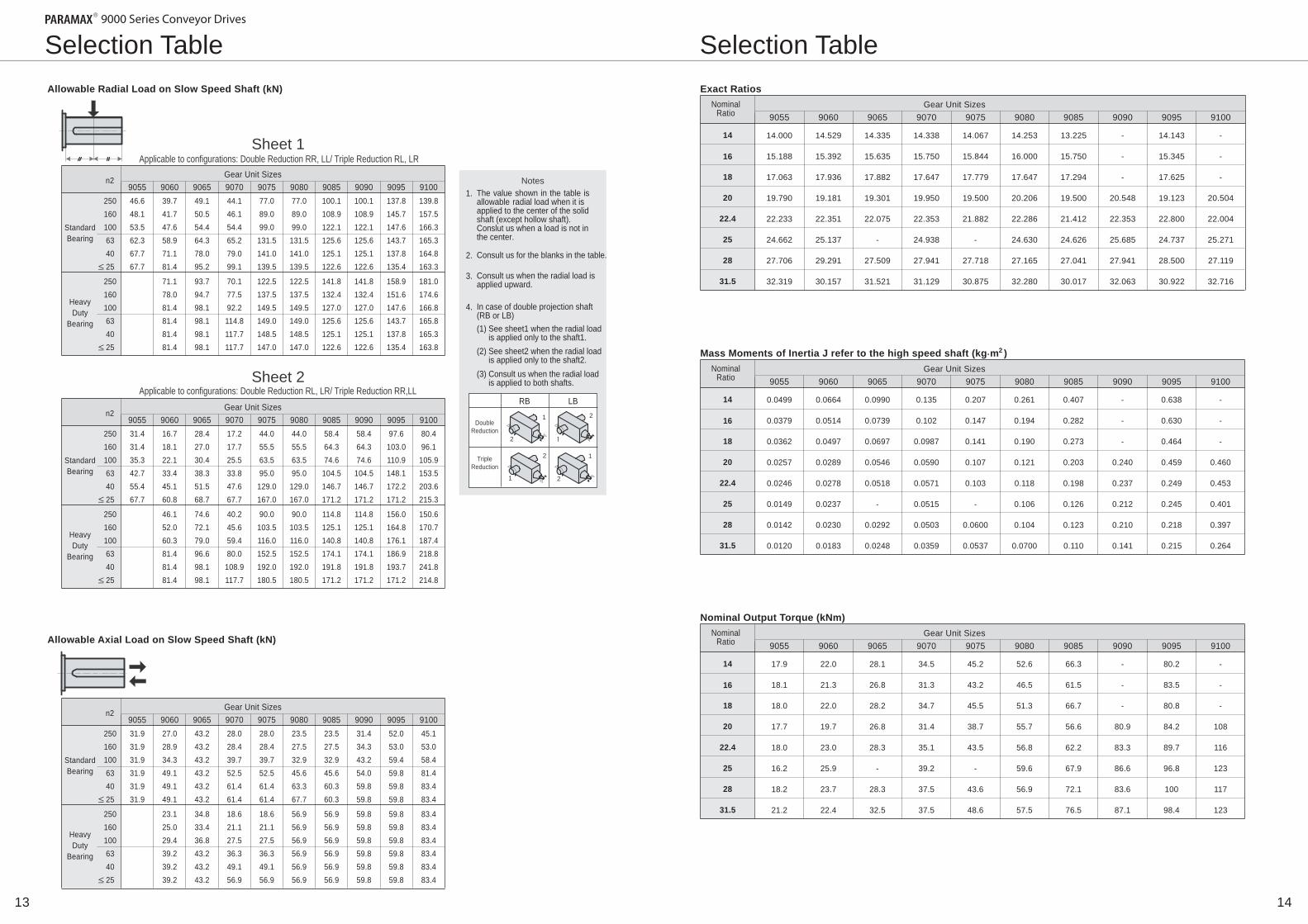
Exact RatiosAllowable Radial Load on Slow Speed Shaft (kN)
Allowable Axial Load on Slow Speed Shaft (kN)
9090 9095 91009055 9060 9065 9070 9075 90859080
14.000
15.188
17.063
19.790
22.233
24.662
27.706
32.319
14.529
15.392
17.936
19.181
22.351
25.137
29.291
30.157
14.335
15.635
17.882
19.301
22.075
-
27.509
31.521
14.338
15.750
17.647
19.950
22.353
24.938
27.941
31.129
14.067
15.844
17.779
19.500
21.882
-
27.718
30.875
14.253
16.000
17.647
20.206
22.286
24.630
27.165
32.280
13.225
15.750
17.294
19.500
21.412
24.626
27.041
30.017
-
-
-
20.548
22.353
25.685
27.941
32.063
14.143
15.345
17.625
19.123
22.800
24.737
28.500
30.922
-
-
-
20.504
22.004
25.271
27.119
32.716
n2Gear Unit Sizes
9090 9095 91009055 9060 9065 9070 9075 9085908046.648.153.562.367.767.7
250160100634025
39.741.747.658.971.181.4
49.150.554.464.378.095.2
44.146.154.465.279.099.1
77.089.099.0
131.5141.0139.5
77.089.099.0
131.5141.0139.5
100.1108.9122.1125.6125.1122.6
100.1108.9122.1125.6125.1122.6
137.8145.7147.6143.7137.8135.4
139.8157.5166.3165.3164.8163.3
250160100634025
71.178.081.481.481.481.4
93.794.798.198.198.198.1
70.177.592.2114.8117.7117.7
122.5137.5149.5149.0148.5147.0
122.5137.5149.5149.0148.5147.0
141.8132.4127.0125.6125.1122.6
141.8132.4127.0125.6125.1122.6
158.9151.6147.6143.7137.8135.4
181.0174.6166.8165.8165.3163.8 Mass Moments of Inertia J refer to the high speed shaft (kg m )2
9090 9095 91009055 9060 9065 9070 9075 90859080
0.0499
0.0379
0.0362
0.0257
0.0246
0.0149
0.0142
0.0120
0.0664
0.0514
0.0497
0.0289
0.0278
0.0237
0.0230
0.0183
0.0990
0.0739
0.0697
0.0546
0.0518
-
0.0292
0.0248
0.135
0.102
0.0987
0.0590
0.0571
0.0515
0.0503
0.0359
0.207
0.147
0.141
0.107
0.103
-
0.0600
0.0537
0.261
0.194
0.190
0.121
0.118
0.106
0.104
0.0700
0.407
0.282
0.273
0.203
0.198
0.126
0.123
0.110
-
-
-
0.240
0.237
0.212
0.210
0.141
0.638
0.630
0.464
0.459
0.249
0.245
0.218
0.215
-
-
-
0.460
0.453
0.401
0.397
0.264
NominalRatio
14
16
18
20
22.4
25
28
31.5
Gear Unit Sizes
Nominal Output Torque (kNm)
9090 9095 91009055 9060 9065 9070 9075 90859080
17.9
18.1
18.0
17.7
18.0
16.2
18.2
21.2
22.0
21.3
22.0
19.7
23.0
25.9
23.7
22.4
28.1
26.8
28.2
26.8
28.3
-
28.3
32.5
34.5
31.3
34.7
31.4
35.1
39.2
37.5
37.5
45.2
43.2
45.5
38.7
43.5
-
43.6
48.6
52.6
46.5
51.3
55.7
56.8
59.6
56.9
57.5
66.3
61.5
66.7
56.6
62.2
67.9
72.1
76.5
-
-
-
80.9
83.3
86.6
83.6
87.1
80.2
83.5
80.8
84.2
89.7
96.8
100
98.4
-
-
-
108
116
123
117
123
Selection Table
1413
Selection Table
Notes 1. The value shown in the table is
allowable radial load when it is applied to the center of the solid shaft (except hollow shaft). Conslut us when a load is not in the center.
2. Consult us for the blanks in the table.
3. Consult us when the radial load is applied upward.
4. In case of double projection shaft (RB or LB) (1) See sheet1 when the radial load
is applied only to the shaft1.(2) See sheet2 when the radial load
is applied only to the shaft2.(3) Consult us when the radial load
is applied to both shafts.
StandardBearing
Heavy Duty
Bearing
n2Gear Unit Sizes
9090 9095 91009055 9060 9065 9070 9075 9085908031.431.435.342.755.467.7
250160100634025
16.718.122.133.445.160.8
28.427.030.438.351.568.7
17.217.725.533.847.667.7
44.055.563.595.0
129.0167.0
44.055.563.595.0
129.0167.0
58.464.374.6
104.5146.7171.2
58.464.374.6
104.5146.7171.2
97.6103.0110.9148.1172.2171.2
80.496.1
105.9153.5203.6215.3
250160100634025
46.152.060.381.481.481.4
74.672.179.096.698.198.1
40.245.659.480.0
108.9117.7
90.0103.5116.0152.5192.0180.5
90.0103.5116.0152.5192.0180.5
114.8125.1140.8174.1191.8171.2
114.8125.1140.8174.1191.8171.2
156.0164.8176.1186.9193.7171.2
150.6170.7187.4218.8241.8214.8
StandardBearing
Heavy Duty
Bearing
n2Gear Unit Sizes
9090 9095 91009055 9060 9065 9070 9075 9085908031.931.931.931.931.931.9
250160100634025
27.028.934.349.149.149.1
43.243.243.243.243.243.2
28.028.439.752.561.461.4
28.028.439.752.561.461.4
23.527.532.945.663.367.7
23.527.532.945.660.360.3
31.434.343.254.059.859.8
52.053.059.459.859.859.8
45.153.058.481.483.483.4
250160100634025
23.125.029.439.239.239.2
34.833.436.843.243.243.2
18.621.127.536.349.156.9
18.621.127.536.349.156.9
56.956.956.956.956.956.9
56.956.956.956.956.956.9
59.859.859.859.859.859.8
59.859.859.859.859.859.8
83.483.483.483.483.483.4
StandardBearing
Heavy Duty
Bearing
Sheet 1 Applicable to configurations: Double Reduction RR, LL/ Triple Reduction RL, LR
Sheet 2 Applicable to configurations: Double Reduction RL, LR/ Triple Reduction RR,LL
Double Reduction
1
2
1
2
2
1
2
TripleReduction
RB LB

Model
Dimensions 9055R2C
Shaft Arrangement 1
Model SizePHD R2C - - Shaft Arrangement Nominal Reduction Ratio1 2 PHD9055R2C - - Shaft Arrangement Nominal Reduction Ratio1
Dimensions 9060R2C~9085R2C
285 345
610
490
150 150
115 115 171
615 845
Shaft Arrangement 2
9000 Series Conveyor Drives PARAMAX
High Speed Shaft End Slow Speed Shaft End
Y2 Z2
X2
W2 S
Y1 X1 Z1
W1 V
High Speed Shaft End Slow Speed Shaft End
5.5 9 14
M16 Depth 36
50k6
11
32 18
M24 Depth 50 120m6
1. Key and keyways are based on ISO R773-1969 Close keys (JIS B 1301-1996 Parallel key in fastening type)2. The oil quantity is approximate. Oil shall be supplied within the range shown on the oil gauge.
(Unit : mm)
A
865911965
101810801136
906090659070907590809085
Size 1
TU
440484509562582585
T
230234259262282285
U
210250250300300300
V
125m6140m6145m6160m6165m6175m6
X2181818182020
Y27777
7.57.5
323636404045
111212131315
182020222225
185225225275275270
Z2111111111212
L2125125125125125125
S
60m660m665m665m675m675m6
906090659070907590809085
R
140140140140140140
W1/Depth
M24/50M30/60M30/60M30/60M30/60M30/60
X1 Y1Key
High Speed Shaft Slow Speed Shaft Cooling FanKey
Z1 L1W2/Depth
M20/42M20/42M20/42M20/42M20/42M20/42
B
318357355402397441
C
725771825878940996
D
151190163210205249
E
265300300335335375
E1
530600600670670750
F
654724723793793873
G
135135160160160160
H
353540525252
J
353542424242
K
180180215220220220
L
885970
1020112011551255
O
310310350350380380
P
380380430430460460
Y
615700700800835935
FA
220220245245270270
FB
180180220220245245
FC
105105105105105105
Weight OilQty
600725920117013001560
293444546276
DP
1”1”1”1”1”1”
kg
1. Key and keyways are based on ISO R773-1969 Close keys (JIS B 1301-1996 Parallel key in fastening type)2. The oil quantity is approximate. Oil shall be supplied within the range shown on the oil gauge.
Size 1
794 684 171 110
95 615
308
411
210
185
285
201
80
RL RR RB LR LL LB RL RR RB LR LL LB
4- 28
4- 28
4- J With Cooling Fan With Cooling Fan
245
245
32
32
190
190
180
FC
FA
FA
FB
O P
F E
1
K K
G G D
Y L
A C D R
L2 Y
B
TU
U
L1
O
T
4- J
E
E
H
H
DP1”
Weight 525 Oil Qty/kg 22
1615

Model
6- 42
Dimensions 9095R2C
Shaft Arrangement 1
1. Key and keyways are based on ISO R773-1969 Close keys (JIS B 1301-1996 Parallel key in fastening type)2. The oil quantity is approximate. Oil shall be supplied within the range shown on the oil gauge.
Model PHD9055R3C - - Shaft Arrangement Nominal Reduction Ratio1 PHD9095R2C - - Shaft Arrangement Nominal Reduction Ratio1
Dimensions 9055R3C
Shaft Arrangement 1 RL RR RB LR LL LB High Speed Shaft End Slow Speed Shaft End
5 8 10
M12 Depth 28
35k6
11
32 18
M24Depth 50120m6
9000 Series Conveyor Drives PARAMAX
1. Key and keyways are based on ISO R773-1969 Close keys (JIS B 1301-1996 Parallel key in fastening type)2. The oil quantity is approximate. Oil shall be supplied within the range shown on the oil gauge.
High Speed Shaft End Slow Speed Shaft End
9 14
25
M24 Depth 50
90m6
15
45 25
M30 Depth 60 190m6
1393 1223 250
250 200 250 250 480
185 525 525 185 570 1420
170 150 525 525
457
700
915
800
400
400
55
55
285 345
345 285
245
245
32
32
350
320
480
350
847 767 171 80
70 615
308
411
210
185
285
201
6- 42
4- 28 150 150
171 115 115 615
845
610
490
4- 28
RL RR RB LR LL LB
1”112”
Weight : 2480kg, Oil Qty : 110 Weight : 510kg, Oil Qty : 25
1817
With Cooling Fan With Cooling Fan
50
190
190
160
135
340
340
220

Model
Dimensions 9060R3C~9085R3C
Shaft Arrangement 2
RL RR RB LR LL LB
Model SizePHD R3C - - Shaft Arrangement Nominal Reduction Ratio1 2 SizePHD R3C - - Shaft Arrangement Nominal Reduction Ratio1 2
Dimensions 9090R3C~9100R3C
Shaft Arrangement 2 RL RR RB LR LL LB
(Unit : mm)
A
132013501474
909090959100
Size 1
TU
650700740
T
350350390
U
300350350
V
180m6190m6200m6
X2181820
Y277
7.5
454545
151515
252525
270320320
Z2111112
L2125125125
S
65m665m675m6
909090959100
R
140140140
W1/Depth
M30/60M30/60M30/60
X1 Y1Key
High Speed Shaft Slow Speed Shaft Cooling FanKey
Z1 L1W2/Depth
M20/42M20/42M20/42
B
427457466
C
118012101334
D
220250224
E
375400425
E1
750800850
F
865915965
G
185185220
H
555560
J
424248
K1
250250290
K2
200200220
L
136014201500
O
480480560
P
570570650
Y
495525530
111
1/21/21/2
FA
340340380
FB
220220245
FC
105105105
Weight OilQty
215023603010
105120150
DP
”””
kg
1. Key and keyways are based on ISO R773-1969 Close keys (JIS B 1301-1996 Parallel key in fastening type)2. The oil quantity is approximate. Oil shall be supplied within the range shown on the oil gauge.
Size 1
A C D R
L2 Y Y
B
TU
U
L1
O
T F E1
K1 K2 K1 D
G Y Y G L
6- J
6- J
O P
E
E
H
H
A C D R
L2
B
TU
U
L1
T F
E1
K K D
G Y G L
4- J
O P
E
E
H
H
(Unit : mm)
A
939985
1027108011761232
906090659070907590809085
Size 1
TU
440484509562582585
T
230234259262282285
U
210250250300300300
V
125m6140m6145m6160m6165m6175m6
X2141414141818
Y25.55.55.55.577
323636404045
111212131315
182020222225
185225225275275270
Z299991111
L295959595
125125
S
45k645k650k650k660m660m6
906090659070907590809085
R
110110110110140140
W1/Depth
M24/50M30/60M30/60M30/60M30/60M30/60
X1 Y1Key
High Speed Shaft Slow Speed Shaft Cooling FanKey
Z1 L1W2/Depth
M16/36M16/36M16/36M16/36M20/42M20/42
B
318357355402397441
C
829875917970
10361092
D
151190163210205249
E
265300300335335375
E1
530600600670670750
F
654724723793793873
G
135135160160160160
H
353540525252
J
353542424242
K
180180215220220220
L
885970
1020112011551255
O
310310350350380380
P
380380430430460460
Y
615700700800835935
FA
220220245245270270
FB
180180180180180180
FC
80808080
105105
Weight OilQty
660785940119013501610
364254647087
DP
1”1”1”1”1”1”
kg
1. Key and keyways are based on ISO R773-1969 Close keys (JIS B 1301-1996 Parallel key in fastening type)2. The oil quantity is approximate. Oil shall be supplied within the range shown on the oil gauge.
Size 1
High Speed Shaft End Slow Speed Shaft End
Y2 Z2
X2
W2 S
Y1 X1 Z1
W1 V
High Speed Shaft End Slow Speed Shaft End
Y2 Z2
X2
W2 S
Y1 X1 Z1
W1 V
Air Breather
Drain Plug
Oil Fill
Inspection Cover
Oil Gauge
Opposite Side
Taconite Seal
Air Breather
Drain Plug
Oil Fill
Inspection Cover
Oil Gauge
Opposite Side
Taconite Seal
DP DP
O
4- J
Y
2019
FC
FA
FA
FB
FC
FA
FA
FB
With Cooling Fan With Cooling Fan

Optional Accessories Optional Accessories
Backstop
Internal backstop is mounted directly on the intermediate shaft of the reducer.Internal type does not require the torque arm for the baskstop, bearing, oil seal, andspecialized lubrication, unlike the exterior-mount type. It makes the application devicemore simple, compact, and maintenance free.
This air breather should be used when installing a gear box in a very dustyenvironment. This unit may be used even in an environment whereby thegear box with a normal air breather becomes buried under dust.
Inner race rotate in single direction only. This is a centrifugal lift-off backstop with no contact of cam.
Specifications
Dimensions
Right Angle Shaft Double Stage Reduction
Right Angle Shaft Triple Stage Reduction
A long nipple is used to raise the unit from the standard installation position, soas to prevent it from becoming buried under dust.
Specifications
A dustproof cover is installed over the air breather to prevent direct accumulationof dust.
9055R2C9060R2C9065R2C9070R2C9075R2C9080R2C9085R2C9095R2C
SIZE
201230234259262282285350
T
210230230290290322322412
BD
320358358
402.5402.5416.5416.5521
BH
249245291285338330386408
BA V U
120125140145160165175190
210210250250300300300350
(Unit : mm)
9055R3C9060R3C9065R3C9070R3C9075R3C9080R3C9085R3C9090R3C9095R3C9100R3C
SIZE
201230234259262282285350350390
T
150175175190190210210290290290
BD
263308308330330365365509509552
BH
397414460482535556612640670724
BA V U
120125140145160165175180190200
210210250250300300300300350350
(Unit : mm)
Backstop
V
BD
BA
U
T
BH
Standard backstop arrangementRRB LLB
Backstop
Standard backstop arrangementRLB RRB RBB LRB LLB LBB
BD
V
BA
BH
U
T
2221
Drain Valve
GS
CX DG
9055906090659070907590809085909090959100
SIZE
133170170155155155155156156161
CX
37313133333434545455
GS DG DP
286286325323370365409405435444
111
1/21/21/2
”””
1111111
”””””””
(Unit : mm)
9055906090659070907590809085909090959100
SIZE
121135135159159178178245245284
B
6737177877868568569369289781028
A C
150150150150150150150150150150
(Unit : mm)
DP
Anti Dust Air Breather
Optional Accessories Optional Accessories
Y
P
9 h / 9 s J X
D
LR(45 ) R
1.6
LS L
LS L
Z1 D
Locking Screw Locking Screw
L4 L5 L3
L2 L1
D 2 . 0 - 4 . 0 -
L / 2
1 D
D2 Z A Z1 D Z
L4 L5 L3
L2 L1 LG
LH
D 2 . 0 - 4 . 0 -
L / 2
1 D
A
U U
9055 9060~9085
Shrink Disk Coupling
Key Coupling
L Size
LS U
9055 9060 9065 9070 9075 9080 9085
10 47 54 54 54 54 54
330 340 350 370 400 400 450
Locking Screw Thread Size Body Length D
j6 115 125 145 145 150 165 175
D2 j6 -
123 143 143 148 163 173
D1 min 130 140 160 160 165 180 190
L5 min 220 260 265 310 365 370 385
Z1 (Deep) L1 L2 L3 L4
350 445 455 500 500 540 540
X
32 32 36 36 40 40 45
Y
18 18 20 20 22 22 25
P
11 11 12 12 13 13 15
R
2.5 3 3 3 3 3 3
300 395 405 445 445 480 480
110 90
100 120 120 125 125
45 5 5 5 5 5 5
M24 M24 M30 M30 M30 M30 M30
(35)(35)(45)(45)(45)(45)(45)
410 470 480 530 530 570 570
LG
356 - - - - - -
LH
388 - - - - - -
Z
M30 M30 M36 M36 M36 M36 M36
LR
3 4.5 4.5 4.5 4.5 4.5 4.5
(Unit : mm)
Shrink DiskSafety Cover
Driven Shaft
M24 M24 M30 M30 M30 M30 M30
65 80
100 100 100 100 100
1. The key and keyway conform to JIS B 1301-1996(ISO) “Sunk keys and keyways” parallel keys (regular class)2. The locking screw and distance ring will not be supplied. Please prepare, if they are necesary.3. Dimension from center of housing to shaft end is L/2
Note :
MODEL Size
d Ds H ZS TA N m
D h7
D1 min
Z
9055 9060 9065 9070 9075 9080 9085 9090 9095 9100
165 165 175 185 200 220 240 240 260 260
290 290 300 330 350 370 405 405 440 440
88 88 88 86 86
104 109 109 120 120
M16 M16 M16 M16 M16 M16 M20 M20 M20 M20
250 250 250 290 284 290 570 570 535 535
205 230 235 260 265 285 285 350 350 390
J LZ LR LV N-ZY DZ LS U dw d1 L1 L2 L3 L4 R
120h6 125h6 140h6 145h6 155h6 170g6 180g6 190g6 200g6 210g6
121 126 141 146 156 171 181 191 201 211
123 128 143 148 158 173 183 193 203 213
138 143 158 163 173 188 198 212 222 234
525 580 589 640 646 709 709 840 855 930
385 435 450 475 475 520 520 635 640 705
120 130 130 160 160 190 190 200 205 215
3 3 5 5 5 5 5 5 5 5
2.5 3 3 3 3 3 3 4.5 4.5 4.5
M24 M24 M30 M30 M30 M30 M36 M36 M36 M36
(35)(35)(45)(45)(45)(45)(55)(55)(55)(55)
528 583 594 644 651 714 714 844 859 934
27 27 26 26 26 26 27 27 27 27
17 12 21 21 21 21 21 21 14 21
314 322 349 371 406 401 456 451 450 491
146 146 157.5 167 177 195 210 215 230 235
4-M12 4-M12 4-M12 4-M12 4-M12 4-M12 4-M12 6-M12 6-M12 6-M12
3 4.5 4.5 4.5 4.5 4.5 4.5 6 6 6
TAS3091. -165 TAS3091. -165 TAS3091. -175 TAS3081. -185 TAS3071. -200 TAS3081. -220 TAS3081. -240 TAS3081. -240 TAS3081.1-260 TAS3081.1-260
(Unit : mm)
Shrink Disk Hollow Shaft
(Deep)
Clampling Bolt Safety CoverDriven Shaft
1. Shrink disk (made by SCHAFER) type No...
Note :
2423
Size A L M (nut)
PR max
S (bellevile spring) DIN2093(nom.) Qty
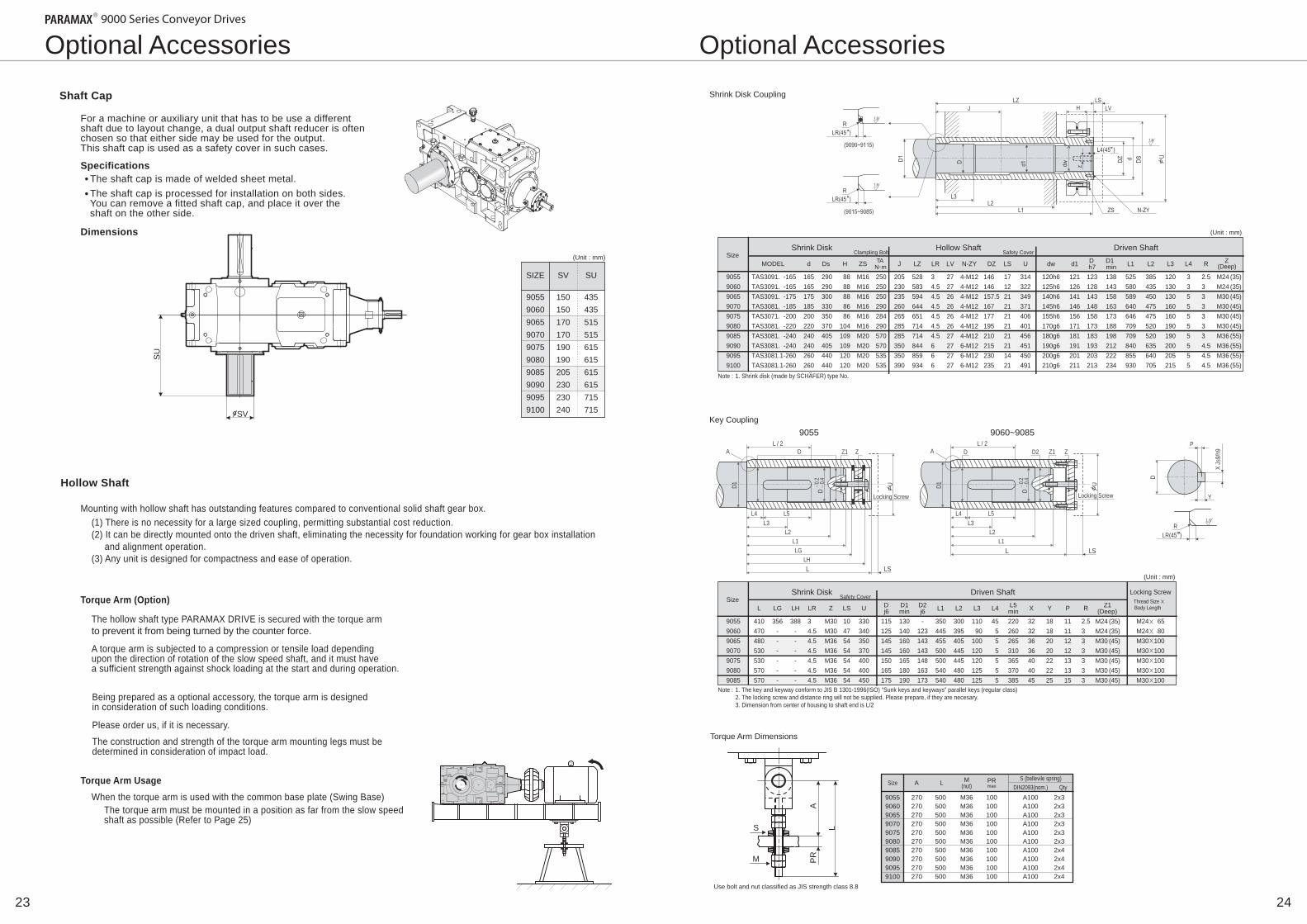
Mounting with hollow shaft has outstanding features compared to conventional solid shaft gear box.
Torque Arm Dimensions
The hollow shaft type PARAMAX DRIVE is secured with the torque armto prevent it from being turned by the counter force.
(1) There is no necessity for a large sized coupling, permitting substantial cost reduction.(2) It can be directly mounted onto the driven shaft, eliminating the necessity for foundation working for gear box installation and alignment operation.(3) Any unit is designed for compactness and ease of operation.
Torque Arm (Option)
When the torque arm is used with the common base plate (Swing Base)The torque arm must be mounted in a position as far from the slow speed shaft as possible (Refer to Page 25)
Torque Arm Usage
A torque arm is subjected to a compression or tensile load dependingupon the direction of rotation of the slow speed shaft, and it must havea sufficient strength against shock loading at the start and during operation.
Being prepared as a optional accessory, the torque arm is designedin consideration of such loading conditions.
Please order us, if it is necessary.
The construction and strength of the torque arm mounting legs must be determined in consideration of impact load.
Use bolt and nut classified as JIS strength class 8.8
Shaft Cap
Hollow Shaft
For a machine or auxiliary unit that has to be use a differentshaft due to layout change, a dual output shaft reducer is oftenchosen so that either side may be used for the output.This shaft cap is used as a safety cover in such cases.
The shaft cap is made of welded sheet metal.The shaft cap is processed for installation on both sides.You can remove a fitted shaft cap, and place it over theshaft on the other side.
Specifications
Dimensions
9055906090659070907590809085909090959100
SIZE
435435515515615615615615715715
SU
150150170170190190205230230240
SV
(Unit : mm)
SV
SU
L
A P
R
S
M
9055906090659070907590809085909090959100
270270270270270270270270270270
500500500500500500500500500500
M36M36M36M36M36M36M36M36M36M36
100100100100100100100100100100
A100A100A100A100A100A100A100A100A100A100
2x32x32x32x32x32x32x42x42x42x4
A B
H
L
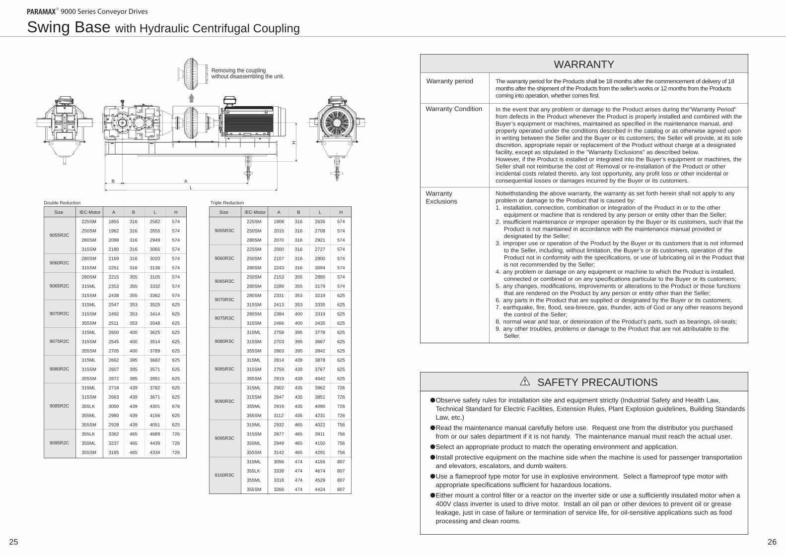
Swing Base with Hydraulic Centrifugal Coupling
Size IEC-Motor A B L H
9055R2C
225SM
250SM
280SM
315SM
280SM
315SM
280SM
315ML
315SM
315ML
315SM
355SM
315ML
315SM
355SM
315ML
315SM
355SM
315ML
315SM
355LK
355ML
355SM
355LK
355ML
355SM
1855
1962
2098
2180
2169
2251
2215
2353
2438
2547
2492
2511
2600
2545
2705
2662
2607
2872
2718
2663
3000
2980
2928
3362
3237
3185
316
316
316
316
316
316
355
355
355
353
353
353
400
400
400
395
395
395
439
439
439
439
439
465
465
465
2582
2655
2949
3065
3020
3136
3105
3332
3362
3525
3414
3548
3625
3514
3789
3682
3571
3951
3782
3671
4301
4156
4051
4689
4439
4334
574
574
574
574
574
574
574
574
574
625
625
625
625
625
625
625
625
625
625
625
676
625
625
726
726
726
9060R2C
9065R2C
9070R2C
9075R2C
9080R2C
9085R2C
9095R2C
Double Reduction
Size IEC-Motor A B L H
9055R3C
225SM
250SM
280SM
225SM
250SM
280SM
250SM
280SM
280SM
315SM
280SM
315SM
315ML
315SM
355SM
315ML
315SM
355SM
315ML
315SM
355ML
355SM
315ML
315SM
355ML
355SM
315ML
355LK
355ML
355SM
1908
2015
2070
2000
2107
2243
2153
2289
2331
2413
2384
2466
2758
2703
2863
2814
2759
2919
2902
2847
2919
3112
2932
2877
2949
3142
3056
3338
3318
3266
316
316
316
316
316
316
355
355
353
353
400
400
395
395
395
439
439
439
435
435
435
435
465
465
465
465
474
474
474
474
2635
2708
2921
2727
2800
3094
2885
3179
3219
3335
3319
3435
3778
3667
3942
3878
3767
4042
3962
3851
4090
4231
4022
3911
4150
4291
4155
4674
4529
4424
574
574
574
574
574
574
574
574
625
625
625
625
625
625
625
625
625
625
726
726
726
726
756
756
756
756
807
807
807
807
9060R3C
9065R3C
9070R3C
9075R3C
9080R3C
9085R3C
9090R3C
9095R3C
9100R3C
Triple Reduction
2625
Warranty Condition
Warranty Exclusions
Warranty period The warranty period for the Products shall be 18 months after the commencement of delivery of 18 months after the shipment of the Products from the seller’s works or 12 months from the Products coming into operation, whether comes first.
In the event that any problem or damage to the Product arises during the"Warranty Period" from defects in the Product whenever the Product is properly installed and combined with the Buyer’s equipment or machines, maintained as specified in the maintenance manual, and properly operated under the conditions described in the catalog or as otherwise agreed upon in writing between the Seller and the Buyer or its customers; the Seller will provide, at its sole discretion, appropriate repair or replacement of the Product without charge at a designated facility, except as stipulated in the "Warranty Exclusions" as described below. However, if the Product is installed or integrated into the Buyer’s equipment or machines, the Seller shall not reimburse the cost of: Removal or re-installation of the Product or other incidental costs related thereto, any lost opportunity, any profit loss or other incidental or consequential losses or damages incurred by the Buyer or its customers.
Notwithstanding the above warranty, the warranty as set forth herein shall not apply to any problem or damage to the Product that is caused by: 1. installation, connection, combination or integration of the Product in or to the other equipment or machine that is rendered by any person or entity other than the Seller; 2. insufficient maintenance or improper operation by the Buyer or its customers, such that the Product is not maintained in accordance with the maintenance manual provided or designated by the Seller; 3. improper use or operation of the Product by the Buyer or its customers that is not informed to the Seller, including, without limitation, the Buyer’s or its customers, operation of the Product not in conformity with the specifications, or use of lubricating oil in the Product that is not recommended by the Seller; 4. any problem or damage on any equipment or machine to which the Product is installed, connected or combined or on any specifications particular to the Buyer or its customers; 5. any changes, modifications, improvements or alterations to the Product or those functions that are rendered on the Product by any person or entity other than the Seller; 6. any parts in the Product that are supplied or designated by the Buyer or its customers; 7. earthquake, fire, flood, sea-breeze, gas, thunder, acts of God or any other reasons beyond the control of the Seller; 8. normal wear and tear, or deterioration of the Product’s parts, such as bearings, oil-seals; 9. any other troubles, problems or damage to the Product that are not attributable to the Seller.
Observe safety rules for installation site and equipment strictly (Industrial Safety and Health Law, Technical Standard for Electric Facilities, Extension Rules, Plant Explosion guidelines, Building Standards Law, etc.) Read the maintenance manual carefully before use. Request one from the distributor you purchased from or our sales department if it is not handy. The maintenance manual must reach the actual user. Select an appropriate product to match the operating environment and application. Install protective equipment on the machine side when the machine is used for passenger transportation and elevators, escalators, and dumb waiters. Use a flameproof type motor for use in explosive environment. Select a flameproof type motor with appropriate specifications sufficient for hazardous locations. Either mount a control filter or a reactor on the inverter side or use a sufficiently insulated motor when a 400V class inverter is used to drive motor. Install an oil pan or other devices to prevent oil or grease leakage, just in case of failure or termination of service life, for oil-sensitive applications such as food processing and clean rooms.
SAFETY PRECAUTIONS
WARRANTY Removing the coupling without disassembling the unit.