
Parallel MuSES for Infrared Signature Modeling of U.S ... · PDF fileParallel MuSES for...
16
Parallel MuSES for Infrared Signature Modeling of U.S. Army Vehicles and Targets by Rama R. Valisetty, Raju R. Namburu, and George Petit ARL-TR-3281 August 2004 Approved for public release; distribution is unlimited.
Transcript of Parallel MuSES for Infrared Signature Modeling of U.S ... · PDF fileParallel MuSES for...
Parallel MuSES for Infrared Signature Modeling
of U.S. Army Vehicles and Targets
by Rama R. Valisetty, Raju R. Namburu, and George Petit
ARL-TR-3281 August 2004
Approved for public release; distribution is unlimited.

NOTICES
Disclaimers The findings in this report are not to be construed as an official Department of the Army position unless so designated by other authorized documents. Citation of manufacturer’s or trade names does not constitute an official endorsement or approval of the use thereof. Destroy this report when it is no longer needed. Do not return it to the originator.

Army Research Laboratory Aberdeen Proving Ground, MD 21005-5067
ARL-TR-3281 August 2004
Parallel MuSES for Infrared Signature Modeling of U.S. Army Vehicles and Targets
Rama R. Valisetty and Raju R. Namburu
Computational and Information Sciences Directorate, ARL
George Petit Raytheon Company, Inc.
Approved for public release; distribution is unlimited.

ii
Report Documentation Page Form Approved OMB No. 0704-0188
Public reporting burden for this collection of information is estimated to average 1 hour per response, including the time for reviewing instructions, searching existing data sources, gathering and maintaining the data needed, and completing and reviewing the collection information. Send comments regarding this burden estimate or any other aspect of this collection of information, including suggestions for reducing the burden, to Department of Defense, Washington Headquarters Services, Directorate for Information Operations and Reports (0704-0188), 1215 Jefferson Davis Highway, Suite 1204, Arlington, VA 22202-4302. Respondents should be aware that notwithstanding any other provision of law, no person shall be subject to any penalty for failing to comply with a collection of information if it does not display a currently valid OMB control number. PLEASE DO NOT RETURN YOUR FORM TO THE ABOVE ADDRESS. 1. REPORT DATE (DD-MM-YYYY)
August 2004 2. REPORT TYPE
Final 3. DATES COVERED (From - To)
January 2002–January 2003 5a. CONTRACT NUMBER
5b. GRANT NUMBER
4. TITLE AND SUBTITLE
Parallel MuSES for Infrared Signature Modeling of U.S. Army Vehicles and Targets
5c. PROGRAM ELEMENT NUMBER
5d. PROJECT NUMBER
H53 5e. TASK NUMBER
6. AUTHOR(S)
Rama R. Valisetty, Raju R. Namburu, and George Petit*
5f. WORK UNIT NUMBER
7. PERFORMING ORGANIZATION NAME(S) AND ADDRESS(ES)
U.S. Army Research Laboratory ATTN: AMSRD-ARL-CI-HC Aberdeen Proving Ground, MD 21005-5067
8. PERFORMING ORGANIZATION REPORT NUMBER
ARL-TR-3281
10. SPONSOR/MONITOR'S ACRONYM(S)
9. SPONSORING/MONITORING AGENCY NAME(S) AND ADDRESS(ES)
DOD MSRC User’s Group 11. SPONSOR/MONITOR'S REPORT NUMBER(S)
12. DISTRIBUTION/AVAILABILITY STATEMENT
Approved for public release; distribution is unlimited. 13. SUPPLEMENTARY NOTES
*Raytheon Company, Inc., 939-I Beards Hill Rd., PMB-191, Aberdeen, MD 21001
14. ABSTRACT
The objective for this work is the parallelization of MuSES, a commercially available computer code for infrared signature modeling of U.S. Army vehicles and targets. During an earlier phase of development in 2002, the progress in this work included (1) profiling of the code for identifying potential segments of thermal and radiation computations for parallelization, (2) selecting a normalization loop within the selective over relaxation (SOR) iteration loop for parallelization by OpenMP, and (3) some results for the ZSU Quad 23 AA vehicle. The results then indicated a scalability performance of some 55% reduction in wall clock computation time on eight processors. Since then, the following parallelization enhancements were added to the code: (1) partial direct solution computation loop within the SOR iteration loop, (2) tri-diagonal solution computation loop within the SOR iteration loop, (3) accelerated solution computation loop within the SOR iteration loop, and (4) routine ComputeRadNodeAveValues. The effectiveness of the enhanced code was evaluated on the previously mentioned ZSU vehicle, a car, and the M2 Bradley Fighting Vehicle. As a result of the enhancements, the maximum performance improvement of the code increased to an average 72% reduction in the wall clock time on 16 processors for computing radiance in the IR range (3–4 µm, 8–12 µm).
15. SUBJECT TERMS
IR modeling
16. SECURITY CLASSIFICATION OF: 19a. NAME OF RESPONSIBLE PERSON Rama R. Valisetty
a. REPORT UNCLASSIFIED
b. ABSTRACT UNCLASSIFIED
c. THIS PAGE UNCLASSIFIED
17. LIMITATION OF ABSTRACT
UL
18. NUMBER OF PAGES
16 19b. TELEPHONE NUMBER (Include area code)
410-278-6638 Standard Form 298 (Rev. 8/98) Prescribed by ANSI Std. Z39.18

iii
Contents
List of Figures iv
List of Tables iv
1. Background 1
2. Parallelization Approach 1
3. Code Segments for Parallelization 2
4. Parallelization Details 3 4.1 Load Balancing................................................................................................................5
4.2 Thermal Node Temperature Change Summation and Maximums..................................5
4.3 Recursions Within Routines Defined in Parallel Regions...............................................5
4.4 Maintaining Thread-Safe Code .......................................................................................5
5. Verification of the Results 6
6. Scalability of the Results 6
7. Future Parallelization Work 8
Distribution List 9

iv
List of Figures
Figure 1. Serial MuSES solver profile. ...........................................................................................3 Figure 2. Flow diagram for Nodal Network solver.........................................................................4 Figure 3. Physical temperature computed at 1900 by the original serial code and the parallel
code. ...........................................................................................................................................6 Figure 4. Prius car mesh..................................................................................................................7 Figure 5. M2 BFV...........................................................................................................................7
List of Tables
Table 1. Mesh details. .....................................................................................................................7 Table 2. Wall clock run times with the initial phase of parallelization. .........................................8 Table 3. Wall clock run times with the second phase of parallelization.........................................8
1
1. Background
MuSES is an acronym for the Multi-Service Electro-Optical Signature Code. While this code is relatively new in Department of Defense (DOD) communities, its predecessors, most notably, the Physically Reasonable Infrared Signature Model on which it is based, have a long and successful history of use in the thermal infrared (IR) modeling of ground vehicles and targets. The code grew mainly out of the need for integrating the many legacy codes and also to make use of the new computing and software programming techniques such as configuration management, etc.
While there are many sponsors from the DOD service agencies from the U.S. Army side, it is the U.S. Army Tank-automotive and Armaments Command Tank-Automotive Research, Development, and Engineering Center which has sponsored the development of the code for a number of years and is currently conducting the validation and verification of version 6.0 of the code. A commercial version of the code, RADTHERM, is widely used (sans radiation) in automotive industries. Both MuSES and RADTHERM are being developed commercially by ThermoAnalytics of Calumet, MI. Help in building and running MuSES models is available.1–3
2. Parallelization Approach
For the present work, a version of the source code was obtained from ThermoAnalytics, Inc. The present work was devoted to making the MuSES code run on parallel computers. This was achieved by using OpenMP.∗ OpenMP is a shared-memory programming standard with parallel regions of computation explicitly identified. This calls for implicit messaging and explicit synchronization. It usually runs with one master process and many slave computing processes and is best suited to run on shared-memory architectures such as SGI Origin 3000* computers. Profiling the source code on an application of interest usually identifies subroutines and code segments that are good candidates for parallelization with OpenMP threads. Only a limited amount of computational scalability is generally achieved with this approach.
The other approach that can lead to a better scalability is based on the message-passing interface (MPI) standard. MPI is usually implemented with domain decomposition. Scalability is
1Makens, C.; Wood, B. MuSES 6.0 User’s Manual; ThermoAnalytics, Inc.: Calumet, MI, 2001. 2MuSES 6.0 Training Manual; ThermoAnalytics, Inc.: Calumet, MI, 2000. 3Gonda, T.; Polsen, E.; Jones, J.; Sass, D.; White, J.; Gerhardt, A.; Less, D.; Rynes, P. A Report on the V&V of MuSES 6.0; draft report; U.S. Army Tank-Automotive Research, Development, and Engineering Center: Warren, MI. ∗OpenMP and SGI Origin 3000 are trademarks of Silicon Graphics, Inc.

2
achieved in numerical codes containing computational meshes, by partitioning the meshes into several submeshes or computational domains. Each domain is assigned to a different processor. Elements internal to a domain are computed independently of calculations on other processors; elements on the interdomain boundaries are computed with neighboring processors exchanging the relevant information in explicit messages. Synchronization of computations (i.e., for time steps, etc.) is a code writer’s responsibility. Since MPI doesn’t require shared-memory architecture, code segments have to be selected with much more understanding of the computational algorithms in a source code rather than with simple profiler knowledge alone.
OpenMP was thus selected for the present work because it allowed the authors to quickly start the parallelization process. Using MPI would have meant more studies of the MuSES computational modules. The code’s many physical processes are coupled and nonlinear. The authors wanted to quickly show that a parallelization of MuSES is possible and a thorough application of either OpenMP or MPI would extend the thermal IR modeling problem space by allowing DOD to leverage its high-performance computing resources for increasing the throughput and lowering the wall clock time.
Results are provided to show the efficiency achieved by the parallel code. Results for physical and apparent temperatures and radiance were computed for the ZSU Quad 23 AA vehicle under four different paint conditions and were verified for accuracy first. For establishing the scalability of the multithreaded code, results were generated from 2-, 4-, 8- and 16- multiprocessor runs. Parallelization work proceeded in two phases. The initial phase focused on a “normalization loop within the selective over relaxation (SOR) iteration loop.” With this parallelization, reduction in the range of 30%–40% in wall clock time in the solver routines was achieved for up to four processors. These results were reported by Petit et al.4 Parallelization of three additional loops in the “SOR iteration loop” and some work in the “ComputeRadNodeAveValues” routine improved the scalability to ~88% reduction in computational time with 16 processors using a test model case.
3. Code Segments for Parallelization
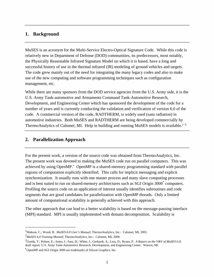
Parallelization by OpenMP multithreads is a gradual process. First, candidate subroutines and code segments are to be determined for opportunities for parallelization from a profile of times spent in various subroutines, as shown in figure 1. The “Nodal Network” solver was identified as a potential candidate subroutine. This subroutine computes for 72.5% of the total time. The parallelization effort, therefore, naturally focused in this area. The flowchart for this routine
4Petit, G.; Valisetty, R.; Namburu, R. Parallel MuSES for Infrared Signature Modeling of Army Vehicles and Targets. Presented at the 13th Annual Ground Target and Validation (GTM&V) Conference, Houghton, MI, August 2002.
3
Figure 1. Serial MuSES solver profile.
is provided in figure 2. In this figure, the computational regions with parallel threads are indicated with a “p” in the upper right-hand corners.
4. Parallelization Details
Based on the code profiling performed, attention was focused on the Nodal Network solver. It begins with initialization and sets up two main loops for time stepping and SOR convergence iteration within each time step. Within each SOR convergence iteration loop, the following major computational steps are performed before evaluating the convergence criteria:
1. Average radiation nodes computation.
2. Partial direct solution computation loop for thermal nodes.
3. Tri-diagonal solution computation loop for thermal nodes.
4. Accelerated solution computation loop for thermal nodes.
5. Normalized solution computation loop for thermal nodes.
Steps 2–5 eventually utilize routines ComputeCondSum and ComputeQRad, which comprise the bulk of the computational time used in the solver. Both of these routines are highly scalar and serial in nature, making them poor candidates for parallelization. Hence, the higher-level loop structures which eventually call these routines became the focus of the parallelization effort. The following subsections summarize the parallelization issues that were encountered and include a synopsis of the implemented solutions.
Solver routines as a percent of overall runtime
27.5%
1.5%2.5%
1.5%
9%
58%
ComputeQRad
ComputeCondSums
ComputeRadNodeAveValues
TsSolveFn
SolveNode
Non-Solver

4
Figure 2. Flow diagram for Nodal Network solver.
p
p
p
p
Partial Direct Sub-solutions
Perform Accelerated Solution
Setup for Direct Solution
Apply SOR for this Node
Update Adaptive Relax. Factor for Nodes
Tri-Diagonal Solutions
SOR Iteration Loop
SolveNode
ComputeCondSums
ComputeQRad
Bottom of Time Stepping Loop
Bottom of SOR Iteration Loop
End TsSolveFN
Time Stepping Loop
Initialization and Setup
TsSolveFn
Compute Radiation Node Average p
Perform Normal Solution

5
4.1 Load Balancing
For the Partial-Direct, Tri-Diagonal and Accelerated solution loops, only a subset of the thermal nodes are processed. For the first two cases, the original code would loop through all thermal nodes and check a variable in the thermal-node structure to determine if that node was defined as appropriate for further processing. This logic could introduce significant load-balancing problems when distributing the calculations across all the thermal nodes within the loop. This problem was overcome by inserting logic in the setup portion of the solver that created separate arrays containing a list of only those thermal nodes being used for partial-direct or tri-diagonal solutions, respectively. The loop structure within the SOR convergence loop was then modified to loop over these new arrays instead of the entire thermal node array. However, some load imbalance is still inherent in the partial-direct loop because each partial-direct thermal node can be associated with 2–24 other nonpartial-direct thermal nodes. This leads to a varying amount of work to migrate the new thermal node values from the partial-direct thermal node to the nonpartial-direct thermal nodes associated with it. For the accelerated computation case, this same solution had already been implemented within the code.
4.2 Thermal Node Temperature Change Summation and Maximums
A product of the Accelerated and Normal solution computations are summations and maximas of all node temperatures, temperature changes, and residuals. The summations were implemented using an OpenMP Reduction clause. Maxima of the temperature changes and residuals were computed for each processor in a parallel fashion in the “SolveNode” subroutine of the block and saved in separate elements of a shared array. The overall maximum was determined by the master process after the parallel computation completed.
4.3 Recursions Within Routines Defined in Parallel Regions
In the “ComputeCondSums” subroutine, nonnative thermal-node temperatures were accessed on the read-only basis so as to preserve the recursive computations that were taking place in it. Also, the code provides the capability to associate multiple thermal nodes with a single radiation node. Because of this capability, ComputeQRad and ComputeRadNodeAveValues update radiation nodes associated with multiple thermal nodes in OpenMP critical regions. This requirement does have performance implications for models utilizing significant numbers of multiply-associated radiation nodes. It is, therefore, recommended that the use of this feature be avoided as much as possible when developing models that will be used by parallel versions of the MuSES code.
4.4 Maintaining Thread-Safe Code
Two nonsolver routines, fluidtable and xydata, modified global (shared) variables that led to erroneous results being generated. These routines were modified to use private copies of shared variables.

6
5. Verification of the Results
For generating the results to verify the accuracy of the included OpenMP multithreads, the ZSU Quad 23 AA vehicle was considered. It was assumed to be at 47.175° latitude and 88.492° longitude, and at a 183.49-m elevation, on 19 July 1984, exposed to ambient atmospheric conditions for 6 hr beginning at 1300. It was considered with four different paint conditions (desert tan, rust, black, and tactical glass).
A mesh for the vehicle was available with 2339 elements, 8853 vertices, and 128 parts; it was selected. Results for the physical and apparent temperatures and radiance (3–4 µm, 8–12 µm) were computed with both the original serial code and the code with the OpenMP multithreads in a 4-processor run. Results from the two codes were identical. Physical temperature results at 1900 are shown in figure 3. Results for the apparent temperature and the 8–12 µm results were also similarly identical, thus verifying that the OpenMP multithreads were properly inserted.
Figure 3. Physical temperature computed at 1900 by the original serial code and the parallel code.
6. Scalability of the Results
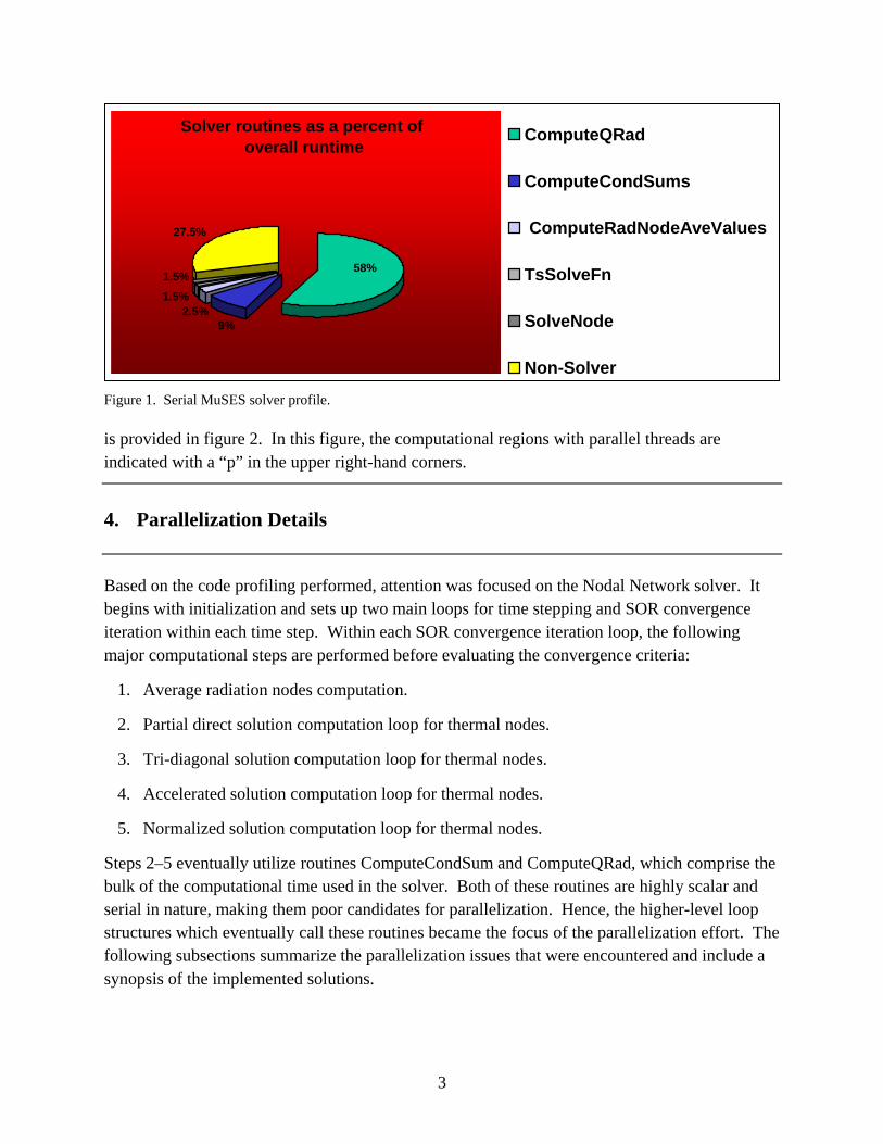
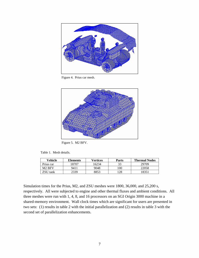
Scalability results are generated on three meshes. The first mesh is the previously mentioned ZSU Quad 23 AA vehicle. The other two are a car and the M2 Bradley Fighting Vehicle (BFV) as shown in figures 4 and 5. The details of the three meshes are listed in table 1.
7
Figure 4. Prius car mesh.
Figure 5. M2 BFV.
Table 1. Mesh details.
Vehicle Elements Vertices Parts Thermal Nodes Prius car 18707 16234 33 29709 M2 BFV 9411 9048 100 22058 ZSU tank 2339 8853 128 18351
Simulation times for the Prius, M2, and ZSU meshes were 1800, 36,000, and 25,200 s, respectively. All were subjected to engine and other thermal fluxes and ambient conditions. All three meshes were run with 1, 4, 8, and 16 processors on an SGI Origin 3000 machine in a shared-memory environment. Wall clock times which are significant for users are presented in two sets: (1) results in table 2 with the initial parallelization and (2) results in table 3 with the second set of parallelization enhancements.

8
Table 2. Wall clock run times with the initial phase of parallelization.
Vehicle 1 proc run (s)
4 proc run (s)
8 proc run (s)
16 proc run (s)
Prius car 16351 8335 7581 7702 ZSU tank 187598 123179 107729 110436 M2 BFV 256898 217163 239927 147084
Source: footnoted reference 4.
Table 3. Wall clock run times with the second phase of parallelization.
Vehicle 1 proc run (s)
4 proc run (s)
8 proc run (s)
16 proc run (s)
Prius car 16351 4746 3825 3334 ZSU tank 187598 63458 62665 64545 M2 BFV 256898 95176 90516 76476
With the initial phase of parallelization, the reductions were significant for the 1–4 processor runs. However, reductions were not maintained from the 8–16 processor runs indicating that scalability was not maintained. This is to be expected, however, since only a part of the MuSES code was parallelized.
But with the second phase parallelization of the four loops, the scalability improved to an average 72% reduction in computation time with 16 processors, as can be seen from table 3.
Scalability of results is also affected by how the runs were made. Since the runs were made in a shared-memory environment, wall clock times are usually affected by other jobs running at the run time. For a strict comparison of run times, jobs must be run in a dedicated bench mark queue. This was not done, however, since such queues are not available to typical users.
7. Future Parallelization Work
Future efforts in this project will include porting the OpenMP parallel version of MuSES to the IBM SP4 platform and converting the parallel version to a message-passing (i.e., MPI) paradigm in order to provide more scalability and portability.

NO. OF NO. OF COPIES ORGANIZATION COPIES ORGANIZATION
9
1 DEFENSE TECHNICAL (PDF INFORMATION CTR ONLY) DTIC OCA 8725 JOHN J KINGMAN RD STE 0944 FT BELVOIR VA 22060-6218 1 COMMANDING GENERAL US ARMY MATERIEL CMD AMCRDA TF 5001 EISENHOWER AVE ALEXANDRIA VA 22333-0001 1 INST FOR ADVNCD TCHNLGY THE UNIV OF TEXAS AT AUSTIN 3925 W BRAKER LN STE 400 AUSTIN TX 78759-5316 1 US MILITARY ACADEMY MATH SCI CTR EXCELLENCE MADN MATH THAYER HALL WEST POINT NY 10996-1786 1 DIRECTOR US ARMY RESEARCH LAB AMSRD ARL CS IS R 2800 POWDER MILL RD ADELPHI MD 20783-1197 3 DIRECTOR US ARMY RESEARCH LAB AMSRD ARL CI OK TL 2800 POWDER MILL RD ADELPHI MD 20783-1197 3 DIRECTOR US ARMY RESEARCH LAB AMSRD ARL CS IS T 2800 POWDER MILL RD ADELPHI MD 20783-1197
ABERDEEN PROVING GROUND 1 DIR USARL AMSRD ARL CI OK TP (BLDG 4600)

10
INTENTIONALLY LEFT BLANK.