Papers Summaries
14
Dual-Band Dual-Polarized Compact Bowtie Antenna Array for Anti-Interference MIMO WLAN Wen Chao Zheng, Long Zhang, Qing Xia Li, Member, IEEE, and Yi Leng, Member, IEEE support anti-interference MIMO WLAN applications. Consist of six antennas for horizontal polarization and six antennas for vertical polarization for three data streams Compact structure and supports the beam switching technique 2.4-GHz and 5-GHz bands for WLAN. Each data stream have four antenna ( Two for horizontal and two for vertical polarization). Proper antenna (for transmission and reception) are selected with RF circuit switch. Six pairs of Meandered slits in horizontal antenna at lower band are used for isolation structure.
-
Upload
ramila-shrestha -
Category
Documents
-
view
239 -
download
1
description
dfgg
Transcript of Papers Summaries
Dual-Band Dual-Polarized Compact Bowtie Antenna
Array for Anti-Interference MIMO WLAN Wen Chao Zheng, Long Zhang, Qing Xia Li,
Member, IEEE, and Yi Leng, Member, IEEE
support anti-interference MIMO WLAN applications.
Consist of six antennas for horizontal polarization and six antennas for vertical polarization for three data streams
Compact structure and supports the beam switching technique
2.4-GHz and 5-GHz bands for WLAN.
Each data stream have four antenna ( Two for horizontal and two for vertical polarization). Proper antenna (for transmission and reception) are selected with RF circuit switch.
Six pairs of Meandered slits in horizontal antenna at lower band are used for isolation structure.
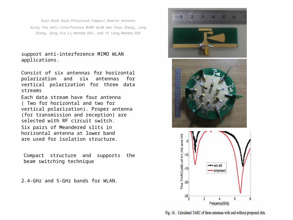
Advanced Precipitation Radar Antenna: Array-Fed Offset Membrane Cylindrical Reflector AntennaYahya Rahmat-Samii, Fellow, IEEE, John Huang, Fellow, IEEE, Bernardo Lopez, Michael Lou, Eastwood Im, Senior Member, IEEE,
Stephen L. Durden, Senior Member, IEEE, and Keyvan Bahadori, Student Member, IEEE
Operates radar channels at both ku and ka band for improved rainfall retrieval accuracy.
Provides the required wide scan angle in the cross-track plane at both operating band frequencies.
Focuses on a half-scale model of 2.65 m operating at Ku and Ka band.
Ku band sub array consists of 2x166 micro-strip patch element
Micro-strip array is selected for the half-scale breadboard model development and its high insertion loss problem can be mitigated for the full-size spacecraft model by using T/R modules in its sub arrays.
A square aperture with rounded corners is proposed to reduce the spillover from wide beam scanning and an offset configuration was adopted to avoid gain loss due to feed blockage.
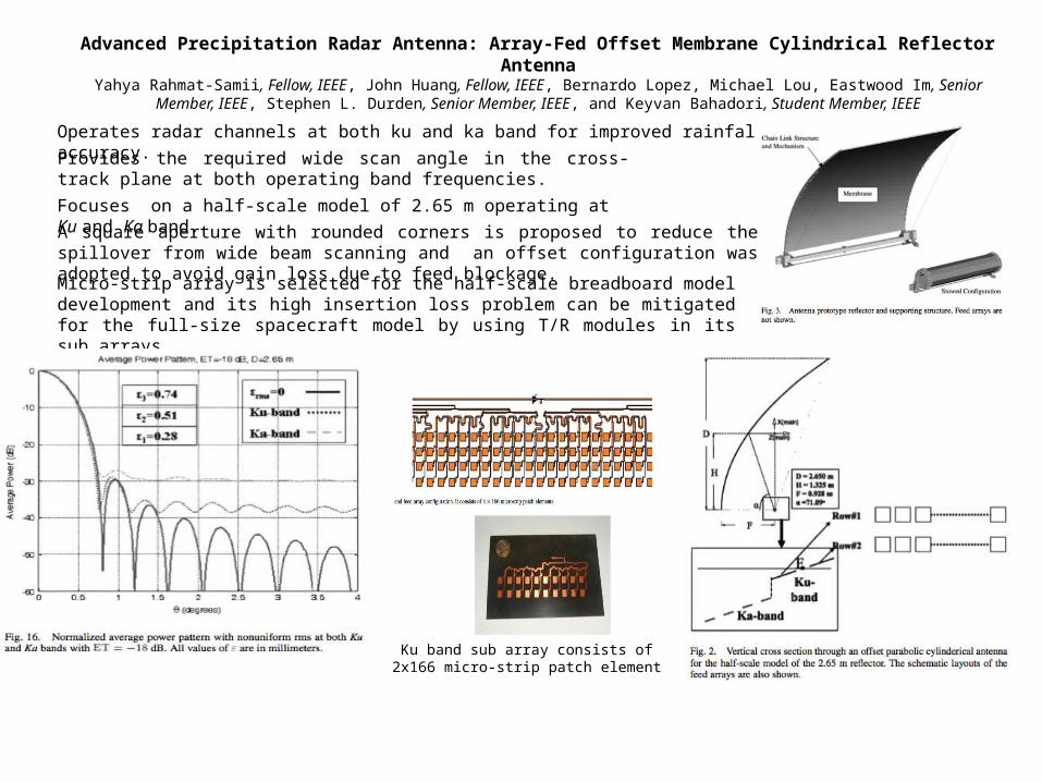
An Offset Linear-Array-Fed Ku/Ka Dual-Band Reflect array for Planet Cloud/Precipitation Radar Shih-Hsun Hsu, Chulmin Han,
John Huang, Fellow, IEEE, and Kai Chang, Fellow, IEEE
First offset-fed reflect array to emulate a cylindrical type of reflector antenna in which new dual-concentric-ring elements and ring-patch elements are uniquely applied.
Reflector array antenna is capable of scanning the main beam at both frequency bands by the two fixed-beam feed arrays with one for broadside beam and the other one for a 20 tilted beam
Geometry of feed antenna array
Measured return loss at 14.1 GHz is 12 dB for the broad- side feed array and is 12.3 dB for the scanned feed array and that at 35 GHz is 17 dB for the broad- side feed array and is 12 dB for the scanned feed array.
The reflect array has dimension of 0.5 m square and a flat aperture that emulates a cylindrical reflector antenna.
Two sets of linear array (one for ku and one for ka band) with linearly polarized micro strip elements and having low cross polarization with low side lobe levels are placed along the focal line and mounted on the supporting arm to illuminate the reflect array.
Provide the capability of the future cloud and precipitation remote sensing system for the Earth and other planets.
A Ka-Band Dual-Frequency Radiator for Array Applications
Emilio Arnieri, Member, IEEE, Luigi Boccia, Member, IEEE, and Giandomenico Amendola, Member, IEEE
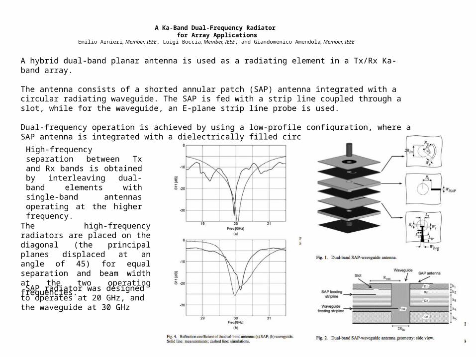
A hybrid dual-band planar antenna is used as a radiating element in a Tx/Rx Ka-band array.
The antenna consists of a shorted annular patch (SAP) antenna integrated with a circular radiating waveguide. The SAP is fed with a strip line coupled through a slot, while for the waveguide, an E-plane strip line probe is used.
Dual-frequency operation is achieved by using a low-profile configuration, where a SAP antenna is integrated with a dielectrically filled circular waveguide.
The high-frequency radiators are placed on the diagonal (the principal planes displaced at an angle of 45) for equal separation and beam width at the two operating frequencies.
SAP radiator was designed to operates at 20 GHz, and the waveguide at 30 GHz
High-frequency separation between Tx and Rx bands is obtained by interleaving dual-band elements with single-band antennas operating at the higher frequency.
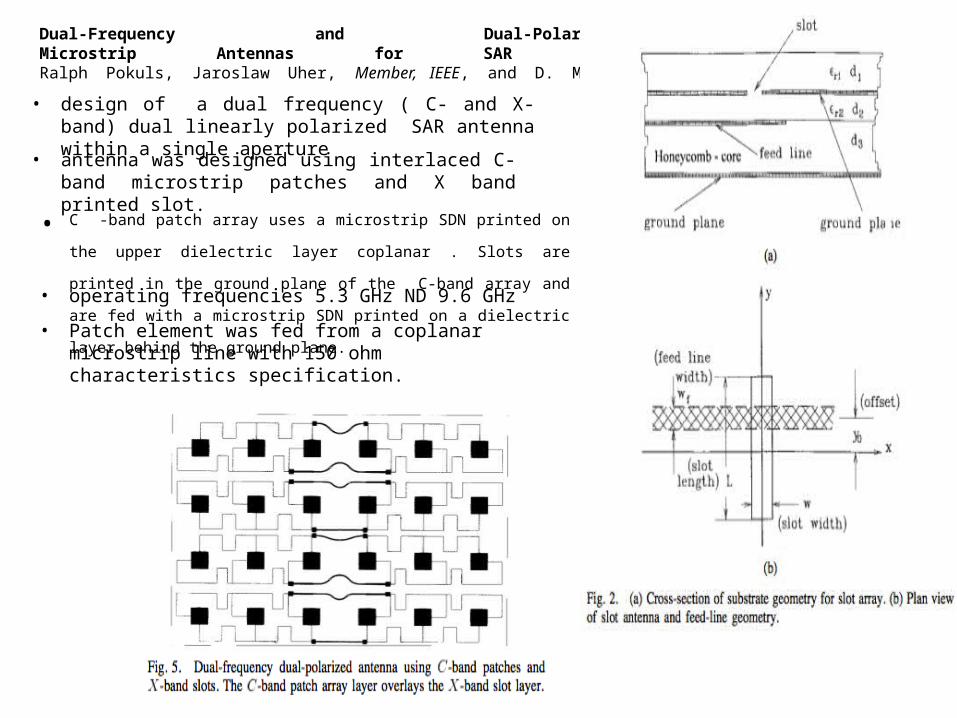
Dual-Frequency and Dual-Polarization Microstrip Antennas for SAR Applications Ralph Pokuls, Jaroslaw Uher, Member, IEEE, and D. M. Pozar, Fellow, IEEE • design of a dual frequency ( C- and X-band) dual linearly
polarized SAR antenna within a single aperture
• antenna was designed using interlaced C-band microstrip patches and X band printed slot.
• C -band patch array uses a microstrip SDN printed on the upper dielectric layer
coplanar . Slots are printed in the ground plane of the C-band array and are fed
with a microstrip SDN printed on a dielectric layer behind the ground plane. • operating frequencies 5.3 GHz ND 9.6 GHz
• Patch element was fed from a coplanar microstrip line with 150 ohm characteristics specification.
A Reconfigurable Patch Antenna Using Switchable Slots for Circular Polarization Diversity Fan Yang, Student Member, IEEE, and Yahya Rahmat-Samii, Fellow, IEEE
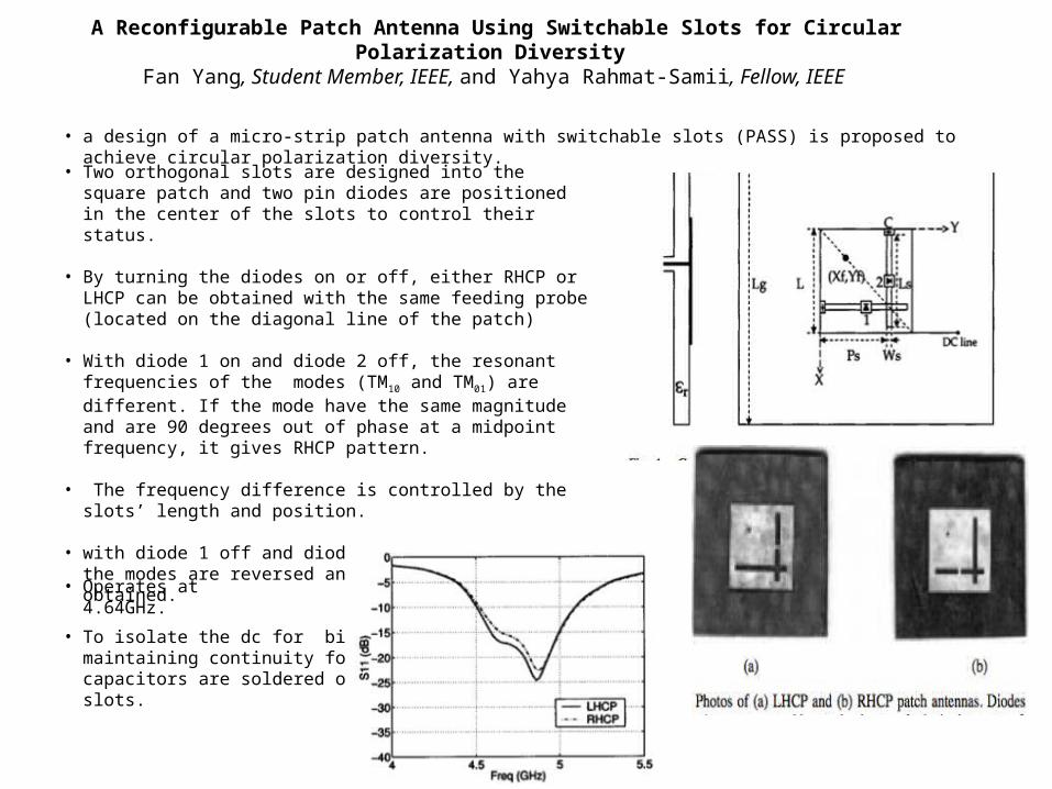
• a design of a micro-strip patch antenna with switchable slots (PASS) is proposed to achieve circular polarization diversity.
• Two orthogonal slots are designed into the square patch and two pin diodes are positioned in the center of the slots to control their status.
• By turning the diodes on or off, either RHCP or LHCP can be obtained with the same feeding probe (located on the diagonal line of the patch)
• With diode 1 on and diode 2 off, the resonant frequencies of the
modes (TM10 and TM01) are different. If the mode have the same magnitude and are 90 degrees out of phase at a midpoint frequency, it gives RHCP pattern.
• The frequency difference is controlled by the slots’ length and position.
• with diode 1 off and diode 2 on, the roles of the modes are reversed and a LHCP pattern can be obtained.
• To isolate the dc for biasing diode while maintaining continuity for the RF, two capacitors are soldered onto the edges of the slots.
• Operates at 4.64GHz.
A Shared-Aperture C/X-Band Dual-Polarized Filtering-Antenna-Array with Shared-Feed and Improved Frequency Response
Chun-Xu Mao, Steven Gao, Member, IEEE, Yi Wang, Senior Member, IEEE, Fan Qin, Qing-Xin Chu, Senior Member, IEEE
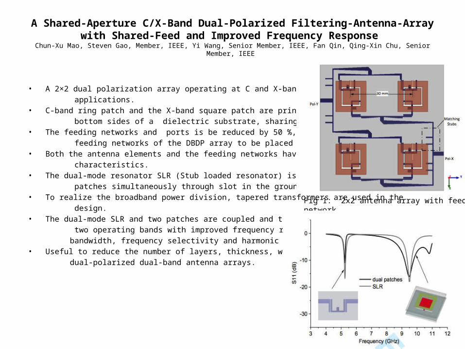
• A 2×2 dual polarization array operating at C and X-band is designed for SAR applications. • C-band ring patch and the X-band square patch are printed on the top and bottom sides of a dielectric substrate, sharing the same aperture.• The feeding networks and ports is be reduced by 50 %, which enables the feeding networks of the DBDP array to be placed in a single layer. • Both the antenna elements and the feeding networks have dual band characteristics.• The dual-mode resonator SLR (Stub loaded resonator) is used to feed the two patches simultaneously through slot in the ground. • To realize the broadband power division, tapered transformers are used in the design. • The dual-mode SLR and two patches are coupled and tuned to produce two operating bands with improved frequency response in terms of bandwidth, frequency selectivity and harmonic suppression. • Useful to reduce the number of layers, thickness, weight and cost of the dual-polarized dual-band antenna arrays.
Fig 1: 2x2 antenna array with feeding network
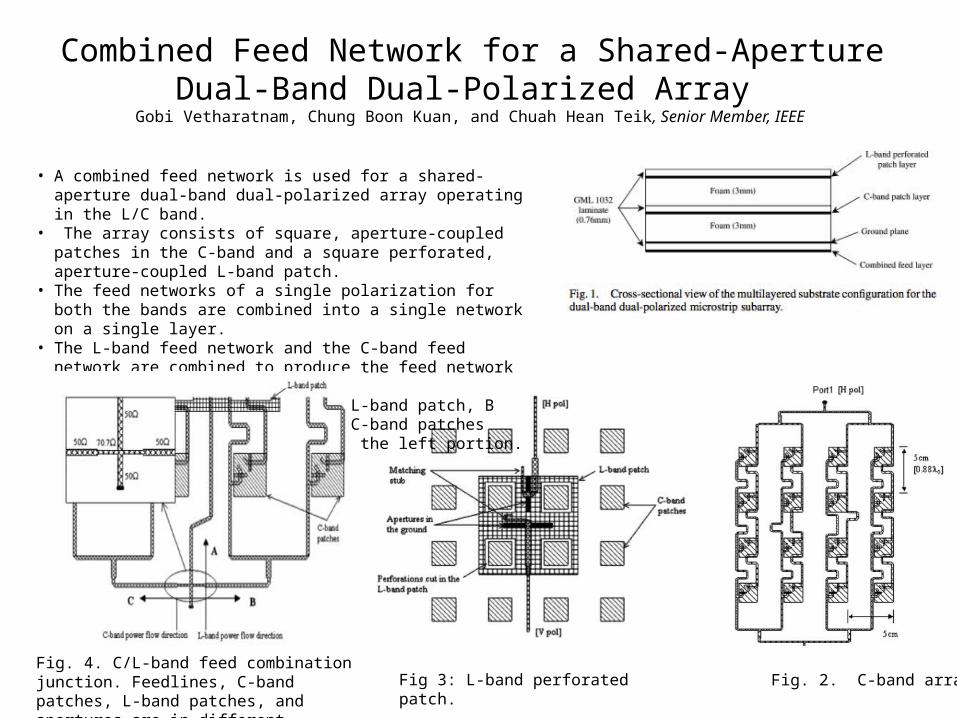
Combined Feed Network for a Shared-Aperture Dual-Band Dual-Polarized Array
Gobi Vetharatnam, Chung Boon Kuan, and Chuah Hean Teik, Senior Member, IEEE
Fig. 2. C-band array. Fig 3: L-band perforated patch.
• A combined feed network is used for a shared-aperture dual-band dual-polarized array operating in the L/C band.
• The array consists of square, aperture-coupled patches in the C-band and a square perforated, aperture-coupled L-band patch.
• The feed networks of a single polarization for both the bands are combined into a single network on a single layer.
• The L-band feed network and the C-band feed network are combined to produce the feed network for the sub-array.
• Transmission line A feeds the L-band patch, B feeds the right portion of the C-band patches while transmission line C feeds the left portion.
Fig. 4. C/L-band feed combination junction. Feedlines, C-band patches, L-band patches, and apertures are in different layers.
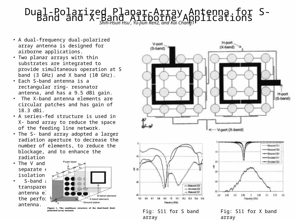
Dual-Polarized Planar-Array Antenna for S-Band and X-Band Airborne Applications Shih-Hsun Hsu', Yu-Jiun Ren2, and Kai Chang1
Fig: S11 for S band array Fig: S11 for X band array
• A dual-frequency dual-polarized array antenna is designed for airborne applications.
• Two planar arrays with thin substrates are integrated to provide simultaneous operation at S band (3 GHz) and X band (10 GHz).
• Each S-band antenna is a rectangular ring- resonator antenna, and has a 9.5 dBi gain.
• The X-band antenna elements are circular patches and has gain of 18.3 dBi.
• A series-fed structure is used in X- band array to reduce the space of the feeding line network.
• The S- band array adopted a larger radiation aperture to decrease the number of elements, to reduce the blockage, and to enhance the radiation gain.
• The V and H ports were put on two separate elements to achieve high isolation.
• S-band antenna is nearly transparent to the X-band antenna element in order to improve the performance of the X-band antenna.
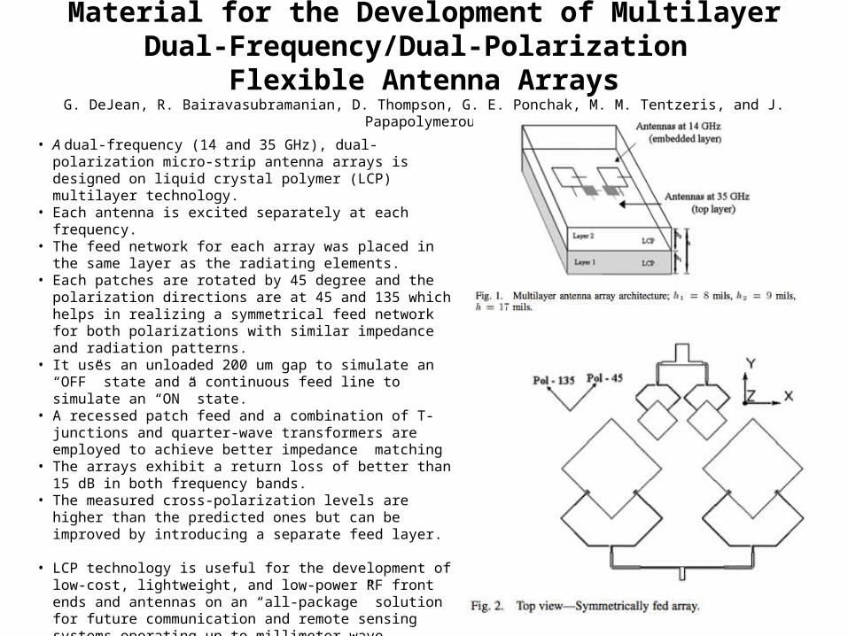
Liquid Crystal Polymer (LCP): A New Organic Material for the Development of Multilayer Dual-Frequency/Dual-Polarization
Flexible Antenna ArraysG. DeJean, R. Bairavasubramanian, D. Thompson, G. E. Ponchak, M. M. Tentzeris, and J. Papapolymerou
• A dual-frequency (14 and 35 GHz), dual-polarization micro-strip antenna arrays is designed on liquid crystal polymer (LCP) multilayer technology.
• Each antenna is excited separately at each frequency.• The feed network for each array was placed in the same layer as the
radiating elements. • Each patches are rotated by 45 degree and the polarization directions
are at 45 and 135 which helps in realizing a symmetrical feed network for both polarizations with similar impedance and radiation patterns.
• It uses an unloaded 200 um gap to simulate an “OFF” state and a continuous feed line to simulate an “ON” state.
• A recessed patch feed and a combination of T-junctions and quarter-wave transformers are employed to achieve better impedance matching
• The arrays exhibit a return loss of better than 15 dB in both frequency bands.
• The measured cross-polarization levels are higher than the predicted ones but can be improved by introducing a separate feed layer.
• LCP technology is useful for the development of low-cost, lightweight, and low-power RF front ends and antennas on an “all-package” solution for future communication and remote sensing systems operating up to millimeter-wave frequency ranges.
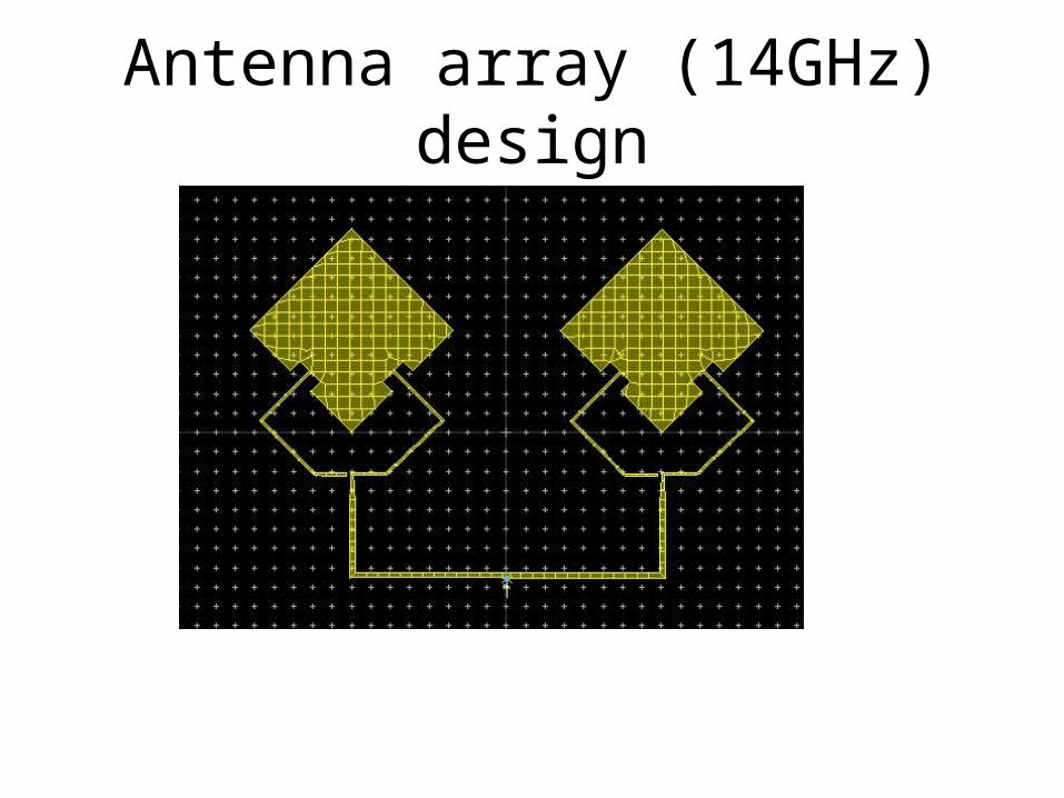
Antenna array (14GHz) design
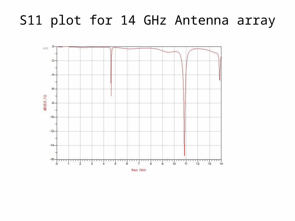
S11 plot for 14 GHz Antenna array
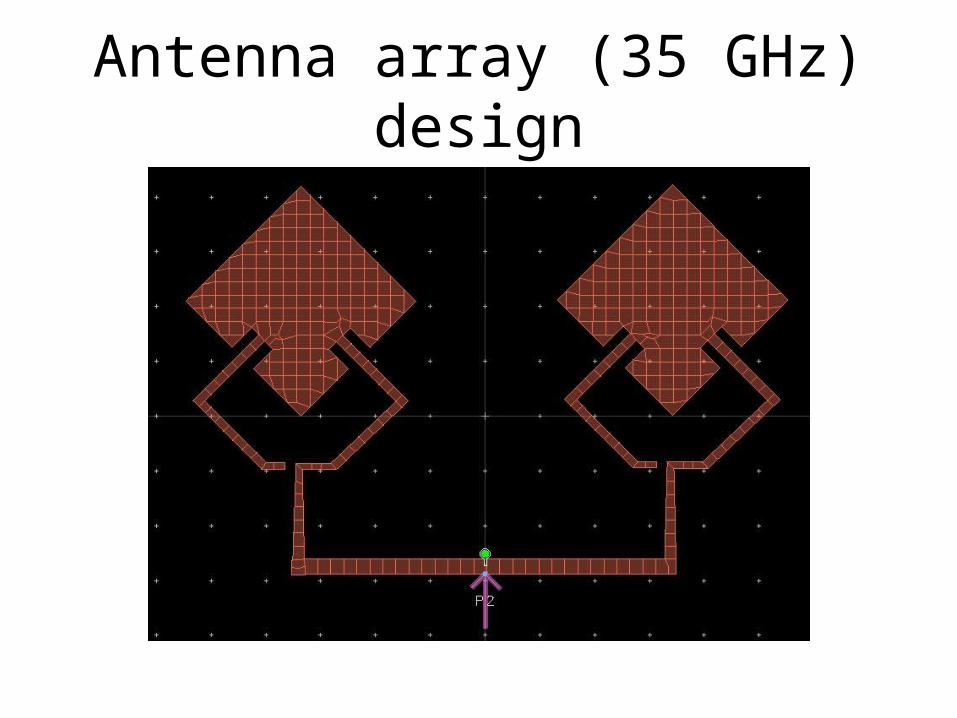
Antenna array (35 GHz) design
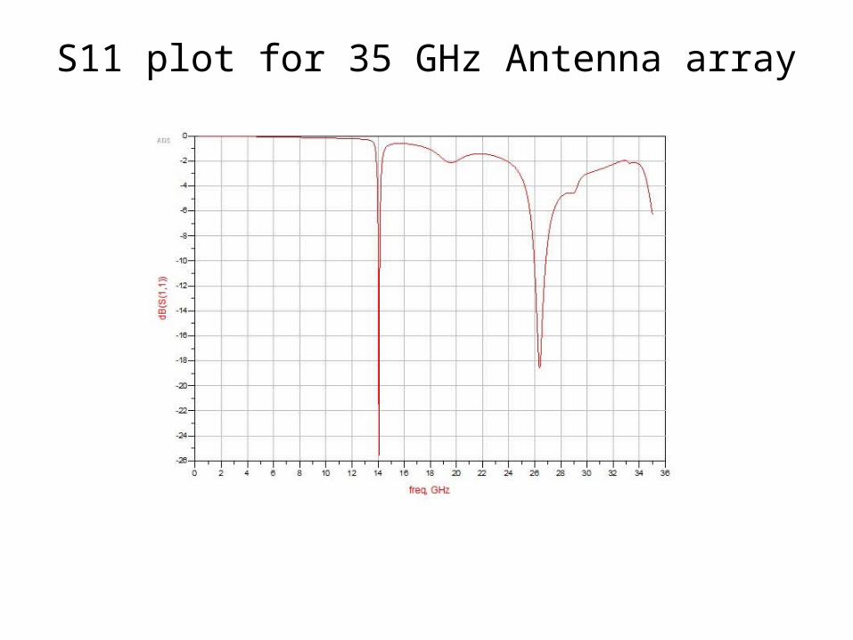
S11 plot for 35 GHz Antenna array