PaperNo. CPI25 - icspl.orgicspl.org/Corcon 2017/html/PDF/CPI25.pdf · HRSGs. Figure1: ... corrosion...
13
Paper No. CPI25 NIGIS * CORCON 2017 * 17-20 September * Mumbai, India Copyright 2017 by NIGIS. The material presented and the views expressed in this paper are solely those of the author(s) and do not necessarily by NIGIS. Failure Analysis and Integrity Assessment of Aging Boiler Bank Tubes of HRSG Maushumi Kakoti Talukdar, Abhay Kujur and Anil Bhardwaj IEOT, Phase II, ONGC , Panvel- Navi Mumbai, Maharashtra-410221 Email: [email protected] ABSTRACT In oil and gas processing plants, heat recovery steam generators (HRSG) continue to make great strides in efficiency and reliability for power generation. But tube failures continue to cause forced outages. To operate at peak capacity, it is necessary for a plant to find ways to avoid tube failures, as well as to quickly recover when forced outages take place. Finding the root cause for a failure is a very important step in preventing future failures. A cogeneration plant installed in one of the gas processing plant was operating HRSG boilers that were in continuous operation for more than 20 years. In one of the boilers, boiler bank tubes failures had been reported a couple of times in a month. Lifetime of tubing was not mentioned by the manufacturer in the manual. Failed tubes were subjected to various laboratory investigations to understand the cause of failure. Corrosion product analysis showed the presence of several ions like Fe, O, Ca, P, Si, Al, Mg, which were deposited on the internal surface of the tube. These deposits acted as an insulator and excessive deposits prevented efficient heat transfer through the tubes to the water. This caused the metal to become overheated. Long term heating caused distinctive microstructural change in both external and internal surface of the tubing due to decarburisation initially around pearlite then gradually spreading leading to intergranular metal loss. From laboratory investigations, it was found that the cause of the metal loss and eventual failure was flow accelerated corrosion (FAC) and erosion. FAC in consonance with microstructural changes resulted in the direct removal of iron from the internal surface of the
-
Upload
truongdien -
Category
Documents
-
view
222 -
download
2
Transcript of PaperNo. CPI25 - icspl.orgicspl.org/Corcon 2017/html/PDF/CPI25.pdf · HRSGs. Figure1: ... corrosion...

Paper No.CPI25
NIGIS * CORCON 2017 * 17-20 September * Mumbai, IndiaCopyright 2017 by NIGIS. The material presented and the views expressed in this paper are solely those of the author(s) and do not necessarily by NIGIS.
Failure Analysis and Integrity Assessment of Aging Boiler BankTubes of HRSG
Maushumi Kakoti Talukdar, Abhay Kujur and Anil BhardwajIEOT, Phase II, ONGC , Panvel- Navi Mumbai, Maharashtra-410221
Email: [email protected]
ABSTRACT
In oil and gas processing plants, heat recovery steam generators (HRSG) continue to makegreat strides in efficiency and reliability for power generation. But tube failures continue tocause forced outages. To operate at peak capacity, it is necessary for a plant to find ways toavoid tube failures, as well as to quickly recover when forced outages take place. Finding theroot cause for a failure is a very important step in preventing future failures.
A cogeneration plant installed in one of the gas processing plant was operating HRSGboilers that were in continuous operation for more than 20 years. In one of the boilers, boilerbank tubes failures had been reported a couple of times in a month. Lifetime of tubing wasnot mentioned by the manufacturer in the manual. Failed tubes were subjected to variouslaboratory investigations to understand the cause of failure.
Corrosion product analysis showed the presence of several ions like Fe, O, Ca, P, Si, Al, Mg,which were deposited on the internal surface of the tube. These deposits acted as aninsulator and excessive deposits prevented efficient heat transfer through the tubes to thewater. This caused the metal to become overheated. Long term heating caused distinctivemicrostructural change in both external and internal surface of the tubing due todecarburisation initially around pearlite then gradually spreading leading to intergranularmetal loss. From laboratory investigations, it was found that the cause of the metal loss andeventual failure was flow accelerated corrosion (FAC) and erosion. FAC in consonance withmicrostructural changes resulted in the direct removal of iron from the internal surface of the

NIGIS * CORCON 2017 * 17-20 September * Mumbai, IndiaCopyright 2017 by NIGIS. The material presented and the views expressed in this paper are solely those of the author(s) and do not necessarily by NIGIS.
tube and made it abrasive, thus accelerating the rate of metal loss from the tube surface byerosion.
A study was carried out on cut samples of otherwise healthy bank tubes of another HRSG toascertain its health and make a comparison of the tube conditions of both HRSGs. The tubesamples were subjected to similar analyses to understand the health, material integrity,morphology of the tube surface. From the laboratory investigations it was found that the tubesurface of this HRSG exhibited morphology similar to the failed tubing. The tubes of thisHRSG are susceptible to failure under FAC and erosion in a manner similar to the failedtubing, as inter-granular metal loss and similar microstructural change were observed in bothtubing.
INTRODUCTION
In oil and gas processing plants, heat recovery steam generators (HRSG) continues to makegreat strides in efficiency and reliability for power generation. But tube failures continue tocause forced outages.
A cogeneration plant installed in one of the gas processing plant was operating two HRSG (I& II) boilers that were in continuous operation for more than 20 years. The boilers HRSG- I &II are of same make, design and commissioned during the same time. They have workedunder the same operating conditions over the last 21 years.. To date, no tube failure hasbeen encountered in HRSG- I (Fig 1) . In HRSG II, boiler bank tubes failures had beenreported a couple of times in a span of one month (Fig 2). Lifetime of tubing was notmentioned by the manufactuer in the manual. Failed tubes were subjected to variouslaboratory investigations with respect to their chemical composition, metallurgy, hardness,and fractography to understand the cause of the failure. As per the OEM these types offailures are common after 20 years of continuous operation. In view of the above observation,similar tests were carried out on the cut samples of otherwise healthy boiler bank tubes ofHRSG- I to ascertain its health and make a comparison of the tube conditions of both theHRSGs.
Figure 1: Boiler bank tubes og HRSG I Figure 2: Failed tubes of HRSG-II

NIGIS * CORCON 2017 * 17-20 September * Mumbai, IndiaCopyright 2017 by NIGIS. The material presented and the views expressed in this paper are solely those of the author(s) and do not necessarily by NIGIS.
Details of the boiler bank tubes :
Material of construction ASTM A 192.Date of Commissioning December 1988Date of first failure of HRSG II 23.04.2009Design pressure, Kg/cm2 , 15Operating pressure, Kg/cm2 7.5Design temperature-oC 200Operating temperature -oC 170Configuration of the line at thelocation of leaks
At bend portions towards upper drum.
Position of the leakage: 12 O’clockDesign life: Lifetime of tubing was not mentioned by the
manufactuer in the manualInternal Environment: Pressurised hot water/ steamExternal Environment Flue gasesAny protection measurestaken during shutdowns toavoid ingress of oxygen.
The boiler was in continuous operation. Shut down wastaken during annual maintenance for about 15 days. Noprotection measures were taken during this period toavoid ingress of oxygen.
Deatil of corrosion protectionmeasures
Na3PO4 and N2H4 were injected daily basis.
EXPERIMENTAL PROCEDURES:
VISUAL INSPECTION:
HRSG II- The OD of the failed tube was 51.2 mm and the ID was 43.2 mm. There was no external corrosion. The tubing had ruptured at the outer periphery of the elbow of the tubes. There was a big hole of 60mm length and 20 mm breadth. Metal near the hole had
thinned down to the extent of 0.88 mm (Figure 2). Internal surface of the tube did not have metal thinning except near the hole. Internal
corrosion typical of flow assisted corrosion was observed at the 12 O’clock side ofthe bend.
HRSG I The OD of the tube was 51.2 mm and the ID was 43.2 mm. There was no external corrosion. Internal surface of the tube did not have metal thinning.
WALL THICKNESS GAUGING:
Wall thickness gauging of the tube samples were carried out by ultrasonic thickness gaugeboth at the plant as well as in the laboratory.

NIGIS * CORCON 2017 * 17-20 September * Mumbai, IndiaCopyright 2017 by NIGIS. The material presented and the views expressed in this paper are solely those of the author(s) and do not necessarily by NIGIS.
ELEMENTAL COMPOSITION ANALYSIS:Chemical compositional analyses of the tubes were carried out by spark
spectrometric analysis as per test method ASTM – E415-99A (2005).
TENSILE STRENGTH TESTTensile strength testing was carried out at room temperature on a longitudinal sample pieceof the tubing as per ASTM A370 specifications. Tensile test included determination of yieldstrength, ultimate tensile strength, and elongation.
CORROSION PRODUCT ANALYSIS BY EDS:The corrosion product was collected from the internal surface of the tubes and
analyzed using SEM-EDS.
STEREOMICROSCOPY:The internal surfaces of the elbow of the HRSG tubes were viewed under astereomicroscope.
METALLURGICAL STUDIES:Sections were cut from the tube samples for detailed microstructural analysis.Metallographic sample preparation was done by grinding the samples with emery papers ofdifferent grits (through 120 to 800 grit sizes). Thereafter these samples were polished withdiamond paste on a polisher to achieve a finish of 1.0. The prepared surface was cleanedproperly and dried. These specimens were observed under an inverted metallurgicalmicroscope (Nikon - EPIPHOT TME) for inclusions/stringers etc. No significant inclusionswere observed. All the specimens were etched with 2% Nital and observed under aninverted metallurgical microscope at different magnifications to study the microstructure.
HARDNESS TESTING:Hardness of the tubing samples were measured on a representative hardness test specimenin the laboratory using a Vickers Hardness tester. Indentations were made with 3.0 kg loadand observed at 400X magnification. Indentations were made across the thickness of thetubing.
SCANNING ELECTRON MICROSCOPIC STUDY:The internal surface of both the HRSG-I and II tube samples were ultrasonically cleaned andwere examined under Scanning Electron Microscope.

NIGIS * CORCON 2017 * 17-20 September * Mumbai, IndiaCopyright 2017 by NIGIS. The material presented and the views expressed in this paper are solely those of the author(s) and do not necessarily by NIGIS.
EXPERIMENTAL RESULTS:
WALL THICKNESS GAUGING
Table 1: Thickness data of the tubes of HRSG II measured at the plant site.
1st rowTube no.
Thickness(mm) 2nd rowTube no.
Thickness(mm)
1. 1.9 39 2.52. 1.6 41 2.23. 1.8 46 2.64 1.9 50 2.5
5-24 plugged 55 2.025 2.4 59 -29 2.2 60 2.133 2.235 1.939 2.241 2.446 2.150 2.355 2.359 2.060 2.162 2.1
Table 2: Thickness data of the boiler tube samples measured at laboratory.
Position on the tube
sample
Measured
thickness
(mm)
HRSG I
Average
Thickness
(mm)
HRSG I
Measured
thickness
(mm)
HRSG II
Average
Thickness
(mm)
HRSG II
12 O’clock (Extrados ofelbow) position
3.3,3.3,3.3 3.3 2.1,2.5, 2.3 2.3
3 O’ clock position 3.5,3.5,3.5 3.5 3.4,3.5, 3.4 3.46 O’ clock (intrados of
elbow position3.6,3.7,3.6 3.6 3.4,3.6, 3.8 3.6
9 O’ clock position 3.3,3.5,3.5 3.5 3.3,3.4, 3.5 3.4
No significant thickness reduction was observed in the tube samples except at the 12O’clock positions (Extrados of elbow) of both HRSG-I and II. In the 12 O’clock positions inthe failed sample of HRSG-II it measured 2.3 mm whereas it measured 3.3 mm for thesample of HRSG-I.

NIGIS * CORCON 2017 * 17-20 September * Mumbai, IndiaCopyright 2017 by NIGIS. The material presented and the views expressed in this paper are solely those of the author(s) and do not necessarily by NIGIS.
ELEMENTAL COMPOSITION ANALYSIS:Table 3: Chemical composition analysis of the tube metal.
The chemical compositional analysis showed that the tube material of both HRSG I andHRSG II conform to ASTM A-192 specifications
TENSILE STRENGTH TESTTable 4: Tensile Strength Test Results for Tube samples
Sl.No.
Parameter ParentMetalHRSG I
ParentMetalHRSG II
Std ASTMA-192
1 Yield strength N/mm2 238 289 180 (min)
2 Tensile strength N/mm2 406 403 325 (min)
3 % Elongation 22.6 27.52 35
Tensile strength, yield strength properties of both HRSG I and HRSG II tube sampleconformed to ASTM A-192 specifications. However, the percentage elongation of bothHRSG I and HRSG II tube samples were not in conformance to ASTM A-192 which may bedue to prolonged exposure of the tube to high temperature.
% CompositionElement
TubeHRSG I
TubeHRSG II
Std ASTM A-192
Carbon 0.086 0.14 0.06-0.18
Silicon 0.23 0.25 0.25 (max)
Manganese 0.50 0.51 0.27-0.63
Phosphorus 0.015 0.020 0.035 (max)
Sulfur 0.008 0.012 0.035 (max)
Nickel 0.016 0.051 -
Chrome 0.019 0.074 -
Molybdenum 0.001 0.023 -
Copper 0.019 0.019 -
Iron Balance Balance Balance

NIGIS * CORCON 2017 * 17-20 September * Mumbai, IndiaCopyright 2017 by NIGIS. The material presented and the views expressed in this paper are solely those of the author(s) and do not necessarily by NIGIS.
CORROSION PRODUCT ANALYSIS BY EDS
Table- 5: EDS analysis of corrosion products in the internal tube surface
Elements Weight%HRSG-I
Weight%HRSG-II
O 20.95 23.96Al 0.39 0.51P 2.49 1.37Ti 0.43 ND*Fe 64.63 65.24Mg 1.29 1.69Si 1.16 3.28Ca 5.65 2.87Mn 2.23 1.09Zn 0.78 ND*
ND*- Not Detected.
Corrosion product analysis showed the presence of several ions like Fe, O, Ca, P, Si, Al, Mg,which were deposited on the internal surface of the tube. These deposits acted as aninsulator and excessive deposits prevented efficient heat transfer through the tubes to thewater
STEREOMICROSCOPY:Under the stereomicroscope,directional pattern of attack fromLeft to right typical of flow assistedcorrosion were observed at theouter surface of the bend. Suchmarks were absent at the otherparts of the bend.
Figure 3: Internal attack in the HRSG-I showing the directional pattern typical of FlowAccelerated Corrosion (FAC)

NIGIS * CORCON 2017 * 17-20 September * Mumbai, IndiaCopyright 2017 by NIGIS. The material presented and the views expressed in this paper are solely those of the author(s) and do not necessarily by NIGIS.
Features typifying the flow acceleratedcorrosion were more pronounced in thefailed tube sample of HRSG-II. Scallopsand directional pattern of internal attack atthe outer surface of the elbow typical ofFAC were clearly visible.
METALLURGICAL STUDIES:The microstructure of the parent metal revealed uniformly distributed pearlite in the matrix offerrite.
Figure 5When carbon steels are exposed to temperatures above 482°C but less than the lowercritical temperature (723°C) this steel is subjected to spheroidization. The carbides presentin the steel in the annealed condition were not in their lower energy state and exposure tohigher temperature resulted in the coalescence of these carbides into spheroidal form.
Due to prolong heating of tubes at the sub critical temperature range, spherodization of thepearlite had taken place. Lamellae of cementite in the pearlite had broken at the ferrite grainboundaries. Both the internal as well as the external surface of the tube had undergonedecarburization as well as metal loss in intergranular manner (Figure 5). The microstructuralfeatures observed on the tube sample of HRSG-I (Figure 6) was identical to those observedon the failed sample of HRSG-II (Figure 7).
Decarburized
Spherodizedregion Normal microstructure
Figure 4: Internal attack in the HRSG-II showing the directional pattern typical of FlowAccelerated Corrosion (FAC)
NIGIS * CORCON 2017 * 17-20 September * Mumbai, IndiaCopyright 2017 by NIGIS. The material presented and the views expressed in this paper are solely those of the author(s) and do not necessarily by NIGIS.
Figures 6 and 7: Internal surface of the tube of HRSG I&II showing ferrite pearlitemicrostructure and intergranular metal loss. (Mag.-200 X ,Etchant-2% Nital)
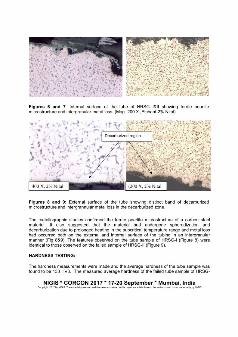
Figures 8 and 9: External surface of the tube showing distinct band of decarburizedmicrostructure and intergrannular metal loss in the decarburized zone.
The metallographic studies confirmed the ferrite pearlite microstructure of a carbon steelmaterial. It also suggested that the material had undergone spherodization anddecarburization due to prolonged heating in the subcritical temperature range and metal losshad occurred both on the external and internal surface of the tubing in an intergranularmanner (Fig 8&9). The features observed on the tube sample of HRSG-I (Figure 8) wereidentical to those observed on the failed sample of HRSG-II (Figure 9).
HARDNESS TESTING:
The hardness measurements were made and the average hardness of the tube sample wasfound to be 138 HV3. The measured average hardness of the failed tube sample of HRSG-
Decarburized region
400 X, 2% Nital (200 X, 2% Nital

NIGIS * CORCON 2017 * 17-20 September * Mumbai, IndiaCopyright 2017 by NIGIS. The material presented and the views expressed in this paper are solely those of the author(s) and do not necessarily by NIGIS.
II was 141 Hv3. Hardness measurement of tube samples of both HRSG-I & II were within thespecified limit for ASTM-A -192 grade materials.
SCANNING ELECTRON MICROSCOPIC STUDY:At the outer bend of the tube sample, morphology typical of FAC attack was observed inboth HRSG I (Figure 10) and HRSG II (Figure 11) samples.
Figure 10: Scallops typical of FAC as observed at the outer bend of HRSG-I.
Figure 11 : Scallops typical of FAC as observed on the failed sample of HRSG II.
NIGIS * CORCON 2017 * 17-20 September * Mumbai, IndiaCopyright 2017 by NIGIS. The material presented and the views expressed in this paper are solely those of the author(s) and do not necessarily by NIGIS.
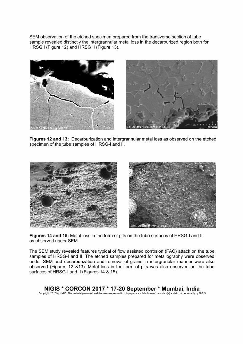
SEM observation of the etched specimen prepared from the transverse section of tubesample revealed distinctly the intergrannular metal loss in the decarburized region both forHRSG I (Figure 12) and HRSG II (Figure 13).
Figures 12 and 13: Decarburization and intergrannular metal loss as observed on the etchedspecimen of the tube samples of HRSG-I and II.
Figures 14 and 15: Metal loss in the form of pits on the tube surfaces of HRSG-I and IIas observed under SEM.
The SEM study revealed features typical of flow assisted corrosion (FAC) attack on the tubesamples of HRSG-I and II. The etched samples prepared for metallography were observedunder SEM and decarburization and removal of grains in intergranular manner were alsoobserved (Figures 12 &13). Metal loss in the form of pits was also observed on the tubesurfaces of HRSG-I and II (Figures 14 & 15).

NIGIS * CORCON 2017 * 17-20 September * Mumbai, IndiaCopyright 2017 by NIGIS. The material presented and the views expressed in this paper are solely those of the author(s) and do not necessarily by NIGIS.
CONCLUSIONS
From the laboratory investigations it was found that the tube surfaces of the HRSG-I and IIhad morphology indicative of flow accelerated corrosion and erosion attack. Corrosionproduct analyses showed the presence of several ions deposited on the internal surface ofthe tubes. These deposits acted as an insulator and excessive deposits prevented efficientheat transfer through the tubes to the water. Prolonged exposure of the tubes underinsulation had resulted in the microstructural changes in both external and internal surfacesof the tubes. Due to prolonged heating of tubes at the sub critical temperature range,spherodization of the pearlite had taken place which deteriorated the mechanical propertiesof the steel. Internal as well as external surface of the tubes was decarburized and gave riseto intergrannular metal loss.
In the case of the tubes of HRSG-II, FAC in consonance with similar microstructural changesresulted in the direct removal of iron from the internal surface of the tube. These metalparticles in turn became abrasive to internal surfaces and potentially accelerated the rate ofmetal loss from the tube surface by erosion which consequently led to its failure.
The tubes of the HRSG I are susceptible to failure under FAC and erosion in a mannersimilar to the failed tubing of HRSG II, as inter-granular metal loss, and similarmicrostructural change were observed in both the tubing. Subsequent to this investigation,the tubes of HRSG-1 also failed in a similar manner to that of the tubes of HRSG II
ACKNOWLEDGEMENTS
The authors hereby acknowledge the whole hearted support and encouragement of ONGCmanagement for providing the necessary infrastructure for carrying out and publishing thiswork. Authors convey their sincere gratitude to ED-HOI-IEOT, for providing opportunity towork on this important project and for encouragement and guidance during the execution ofthis project.
REFERENCES
1. Optical microscopy of carbon steels, L.E.Samuels, ASM, 1992.
2. Background to the design of HRSG systems and implications for CCGT plant cycling.Fred Starr, European Technology development, Surrey, UK.OMMI (Vol-2, Issue-1), April2003.
3. Failure analysis and investigation methods for boiler tube failures, Mehrooz Zamanzadeh,Eward S. Larkin and Geaorge T. Bayer, Paper no. 07450, NACE Corrosion Conference andExpo 2007.
4. HRSG Tube Failures: Prediction, Diagnosis and Corrective Actions Frederick C.Anderson, Peter S. Jackson, and David S. Moelling. CORROSION 2003 Paper 03495

NIGIS * CORCON 2017 * 17-20 September * Mumbai, IndiaCopyright 2017 by NIGIS. The material presented and the views expressed in this paper are solely those of the author(s) and do not necessarily by NIGIS.
5. Analysis of Heat Recovery Steam Generator Tube Failures, David Kotwica, P.E.CORROSION 2003, Paper No. 3487.
6. Case Histories Of Failures In Heat Recovery Steam Generating Systems
a. J. J. Dillon and P. B. Desch, CORROSION 2003 Paper No. 3488.
7. Investigation on the Failure of Boiler tubes in SWCC Jeddah Power Plant.
a. Anees U. Malik etal , KFUPM, 27-30 November, 1994, Dhahran.
8. Standard Specifications for Seamless Carbon steel Boiler tubes for High pressureservice. ASTM- A 192 /A (Reapproved 2007).
9. Standard Specifications for Seamless Ferritic and Austenitic Alloy- Steel Boiler,Superheater, and Heat Exchanger Tubes. ASTM Designation A213/a 213M -09 a
10. Standard Specification for General Requirements for Carbon and Low alloy Steel Tubes.ASTM Designation A 450/ A 450M -07.