Paper Recycling Technology - Nc State...
209
Lecture: Wash Deinking
-
Upload
truongthuy -
Category
Documents
-
view
219 -
download
4
Transcript of Paper Recycling Technology - Nc State...
Lecture:
Wash Deinking

Deinking Washers
Definition: a separation device that rinses small particulate contaminants away from fibers (opposite of screening)
Deinking Washer: Dilute pulp with wash water Disperse small contaminant in water phase,
sometimes aided with a dispersant chemical Remove contaminant laden water

Deinking Washers
Washers in recycling remove all of the following small contaminants fines filler inks dissolved species
In order for washing to be successful, the intended contaminant must be small and must be detached from the fibers
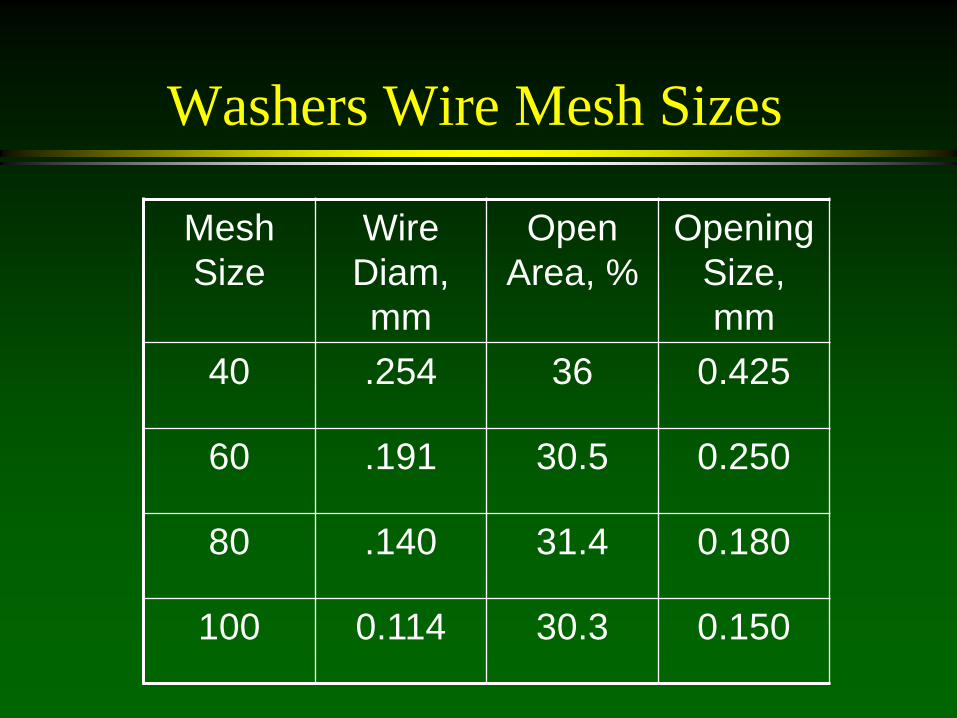
Washers Wire Mesh Sizes
Mesh Size
Wire Diam, mm
Open Area, %
Opening Size, mm
40 .254 36 0.425
60 .191 30.5 0.250
80 .140 31.4 0.180
100 0.114 30.3 0.150
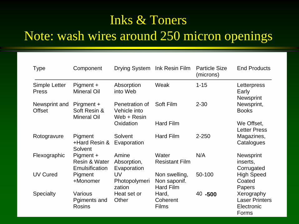
Inks & Toners Note: wash wires around 250 micron openings
Type Component Drying System Ink Resin Film Particle Size(microns)
End Products
Simple LetterPress
Pigment +Mineral Oil
Absorptioninto Web
Weak 1-15 LetterpressEarlyNewsprint
Newsprint andOffset
Pirgment +Soft Resin &Mineral Oil
Penetration ofVehicle intoWeb + ResinOxidation
Soft Film
Hard Film
2-30 Newsprint,Books
We Offset,Letter Press
Rotogravure Pigment+Hard Resin &Solvent
SolventEvaporation
Hard Film 2-250 Magazines,Catalogues
Flexographic Pigment +Resin & WaterEmulsification
AmineAbsorption,Evaporation
WaterResistant Film
N/A Newsprintinserts,Corrugated
UV Cured Pigment+Monomer
UVPhotopolymerization
Non swelling,Non saponif.Hard Film
50-100 High SpeedCoatedPapers
Specialty VariousPgiments andRosins
Heat set orOther
Hard,CoherentFilms
40+ XerographyLaser PrintersElectronicForms
-500
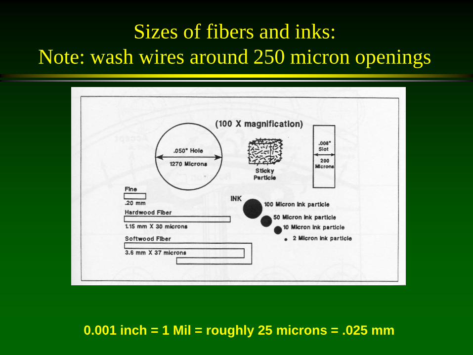
Sizes of fibers and inks: Note: wash wires around 250 micron openings
0.001 inch = 1 Mil = roughly 25 microns = .025 mm
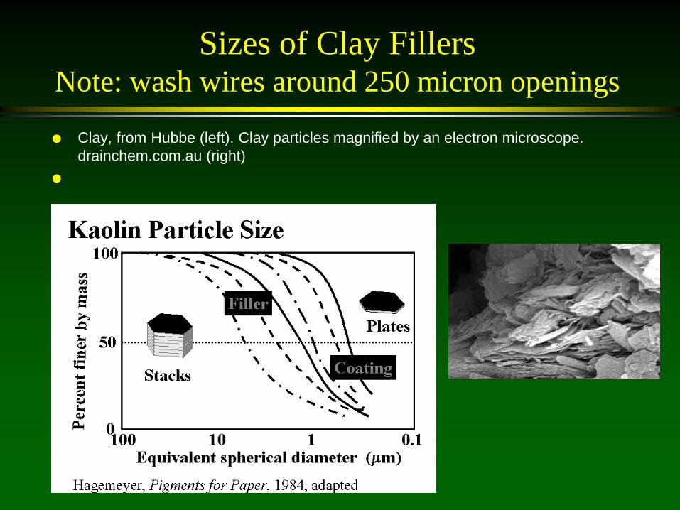
Sizes of Clay Fillers Note: wash wires around 250 micron openings
Clay, from Hubbe (left). Clay particles magnified by an electron microscope. drainchem.com.au (right)
Thickening vs. Dilution Washing
Thickeners purpose to increase consistency fiber mat formation ok lower yield losses
Deinking (Dilution) Washers purpose is to remove contaminant particles fiber mat formation avoided higher yield losses

Pulp mats prevent the removal of small particles in washing.
Type
Inlet % K
Outlet % K
Ash Removal %, Theoretical
Ash Removal %,
Actual
Pulp Mat Formation
Sidehill Scrn 0.8 3 74 60 Minimal Grav Decker 0.8 5 85 55 Yes Incl. Screw 3.0 10 72 45 Extensive Horiz. Screw Press
4.0 28 89 35 Extensive
Belt Washer 1.0 10 80 Minimal Vario Split 0.8 10 85 80 Minimal

Types of Washers
Low Consistency Washers Intermediate Consistency Washers High Consistency Washers

Low Consistency Washers
Up to 8% discharge consistency side-hill screen gravity decker DSM screen Hydrasieve
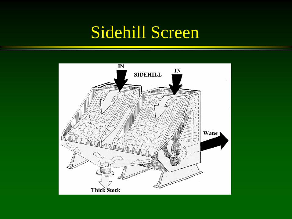
Sidehill Screen
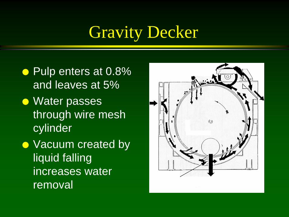
Gravity Decker
Pulp enters at 0.8% and leaves at 5%
Water passes through wire mesh cylinder
Vacuum created by liquid falling increases water removal

Gravity Decker
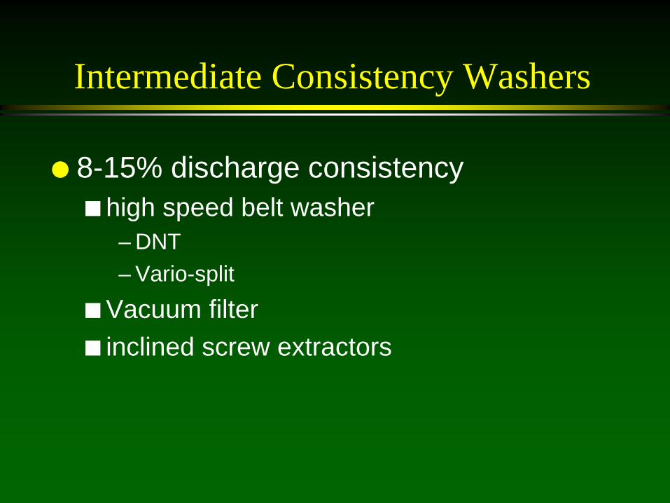
Intermediate Consistency Washers
8-15% discharge consistency high speed belt washer
– DNT – Vario-split
Vacuum filter inclined screw extractors
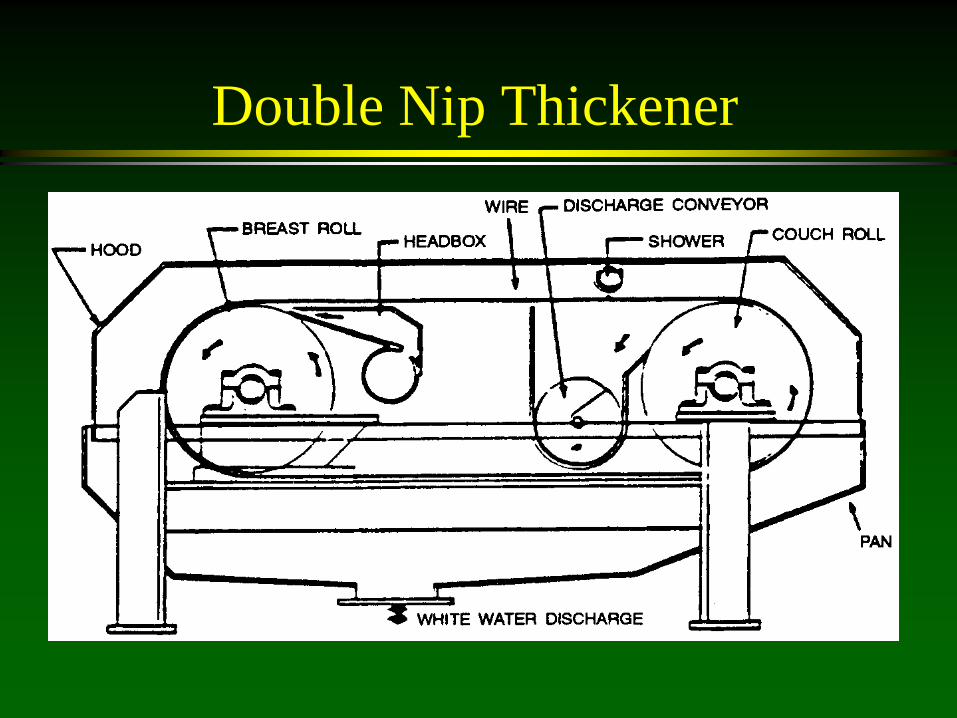
Double Nip Thickener

Double Nip Thickener
DNT Washer “double nip
thickener”

Disk Filter:
Filtrate Laden With Ink

Vacuum Disk Filter Mainly for thickening

Overview
Overview
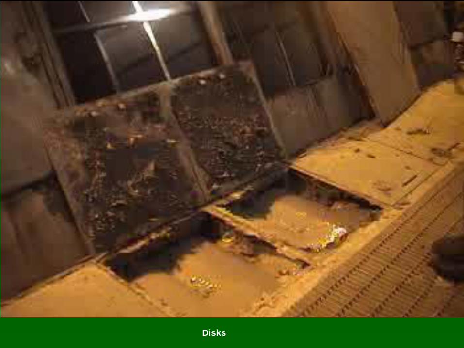
Disks

High Consistency “Washers”
Not really designed as washers, but more designed to thicken
Above 15% discharge consistency screw press belt press Wet lap pulp machine
Low to small contaminant (ink) removal efficiency
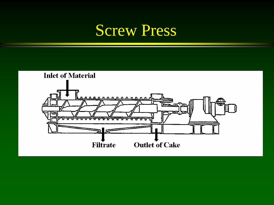
Screw Press

Pressing
HC-Press

Wet-Lap Pulp Machine
A double-wire press is utilized for initial dewatering of the stock to achieve up to 40% bone-dry consistency. The dryness is raised to 48-50% bone-dry by a heavy duty press. The pulp web is then slit and cut into sheets by a rotating knife drum. The sheets drop
onto a pallet.

General concepts in washing:
There are several equipment variables and operating variables that determine the washing efficiency

Washers Wire Mesh Sizes
Mesh Size
Wire Diam, mm
Open Area, %
Opening Size, mm
40 .254 36 0.425
60 .191 30.5 0.250
80 .140 31.4 0.180
100 0.114 30.3 0.150

Pulp mats prevent the removal of small particles in washing
Type
Inlet % K
Outlet % K
Ash Removal %, Theoretical
Ash Removal %,
Actual
Pulp Mat Formation
Sidehill Scrn 0.8 3 74 60 Minimal Grav Decker 0.8 5 85 55 Yes Incl. Screw 3.0 10 72 45 Extensive Horiz. Screw Press
4.0 28 89 35 Extensive
Belt Washer 1.0 10 80 Minimal Vario Split 0.8 10 85 80 Minimal
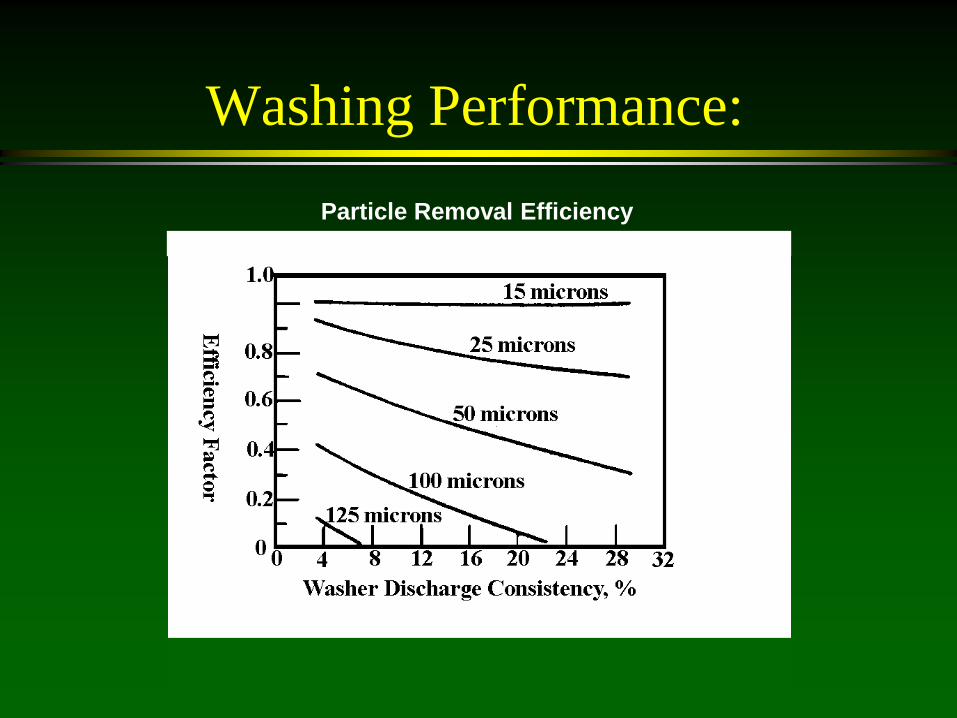
Washing Performance: Particle Removal Efficiency

Washing Performance Theoretical Ink Removed In One Washing Stage
Outlet %K

Washing Performance
Countercurrent washing
Pulper
No. 1 Washer
No. 2 Washer
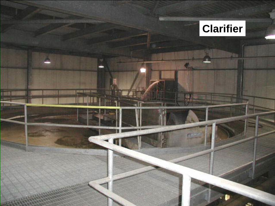
No. 3 Washer
Clarifier
Pulp Filtrate
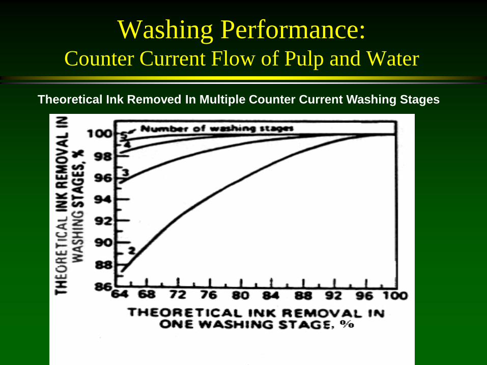
Washing Performance: Counter Current Flow of Pulp and Water
Theoretical Ink Removed In Multiple Counter Current Washing Stages

Lecture:
Flotation
Flotation
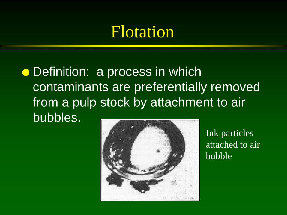
Definition: a process in which contaminants are preferentially removed from a pulp stock by attachment to air bubbles. Ink particles
attached to air bubble
Flotation
In 1992, about 80% of the de-inking plants in the US used flotation
Since the 1950’s flotation cell design has steadily improved

Example Flotation Cell
1. Air bubbles & low consistency stock introduced together.
2. Air bubbles & stock are mixed.
3. Stock travels toward exit of flotation device.
4. Air bubbles rise. 5. Foam removed as
rejects. 6. Accepted stock removed
from cell. 1
2
4 3
5
6
Voith Paddle Cell, 1960’s technology

Flotation
Mechanism: For successful flotation of a contaminant (e.g., ink) several sub-processes must occur: 1. The ink must be free from the fibers. 2. Ink must collide with an air bubble. 3. A strong attachment must form between the ink & the
bubble. 4. The ink-bubble must rise to the surface. 5. The ink-bubble must be incorporated into the foam. 6. The foam must be removed from the system.
Flotation
What determines the flotation efficiency? Contaminant characteristics
Bubble characteristics
Process conditions

Effect of Contaminant Characteristics on Flotation Efficiency
Given two types of particles suspended in water, which one will attach and be removed by an air bubble?
– Hydrophobicity – Detachment from fibers – Size – Shape – Density
Contaminant Characteristics: Hydrophobicity
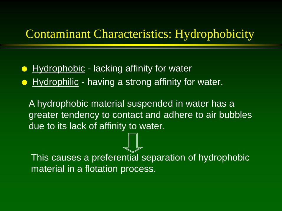
Hydrophobic - lacking affinity for water Hydrophilic - having a strong affinity for water.
A hydrophobic material suspended in water has a greater tendency to contact and adhere to air bubbles due to its lack of affinity to water.
This causes a preferential separation of hydrophobic material in a flotation process.
Contaminant Characteristics: Hydrophobicity
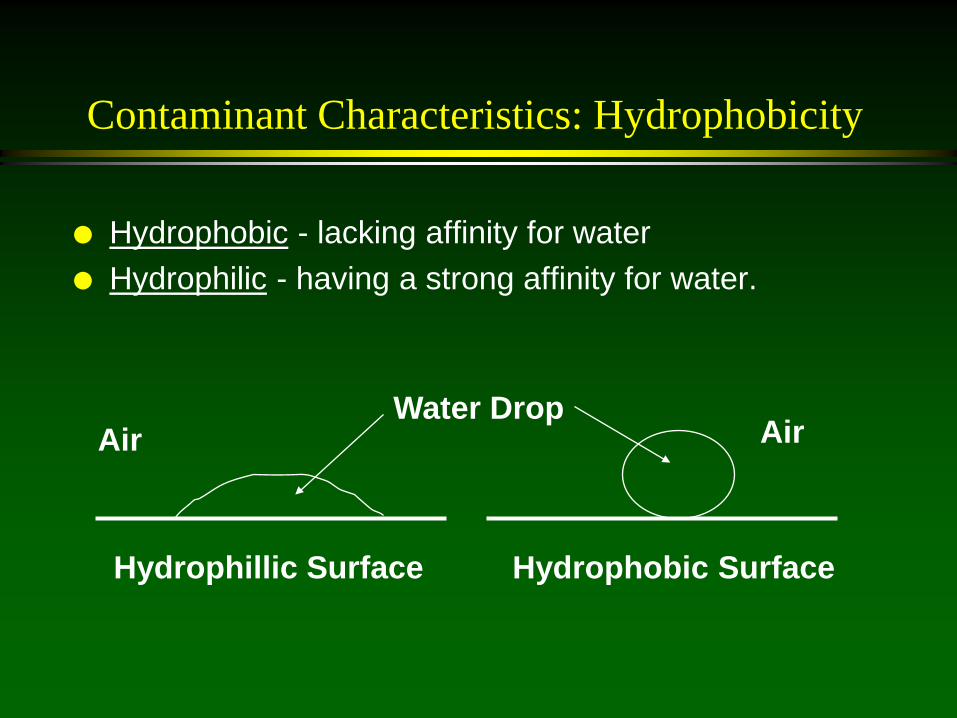
Hydrophobic - lacking affinity for water Hydrophilic - having a strong affinity for water.
Hydrophillic Surface Hydrophobic Surface
Water Drop Air Air
Contaminant Characteristics: Detachment from Fibers
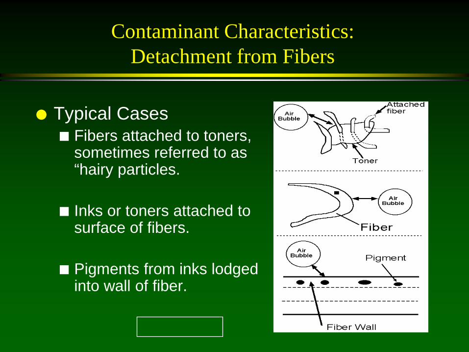
Typical Cases Fibers attached to toners,
sometimes referred to as “hairy particles.
Inks or toners attached to surface of fibers.
Pigments from inks lodged into wall of fiber.

Contaminant Characteristics: Ink size
Ink very small: the ink travels around the bubble in the stream line, does not have enough momentum to cross stream line and attach to bubbles
Ink very large: ink’s weight and large size promotes detachment from bubble surface due to gravity and fluid forces

Collector Soaps
Historically, for ONP deinking, salts of fatty acids combined with calcium ions in the flotation cell have been used to collect fine ink particles into agglomerates
OMG added to provide ash for agglomerates
The agglomerates, because of their size, are removed at higher efficiency

Synthetic Collectors
Non-ionic and ionic surfactants Also called displectors because they can
disperse in washing and collect in flotation
Do not require calcium, reduces deposits
Lower dosages needed (0.2% rather than 0.7% of fatty acids)
Bubble Characteristics
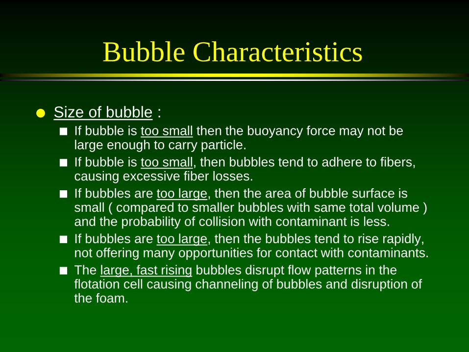
Size of bubble : If bubble is too small then the buoyancy force may not be
large enough to carry particle. If bubble is too small, then bubbles tend to adhere to fibers,
causing excessive fiber losses. If bubbles are too large, then the area of bubble surface is
small ( compared to smaller bubbles with same total volume ) and the probability of collision with contaminant is less.
If bubbles are too large, then the bubbles tend to rise rapidly, not offering many opportunities for contact with contaminants.
The large, fast rising bubbles disrupt flow patterns in the flotation cell causing channeling of bubbles and disruption of the foam.
Bubble Characteristics
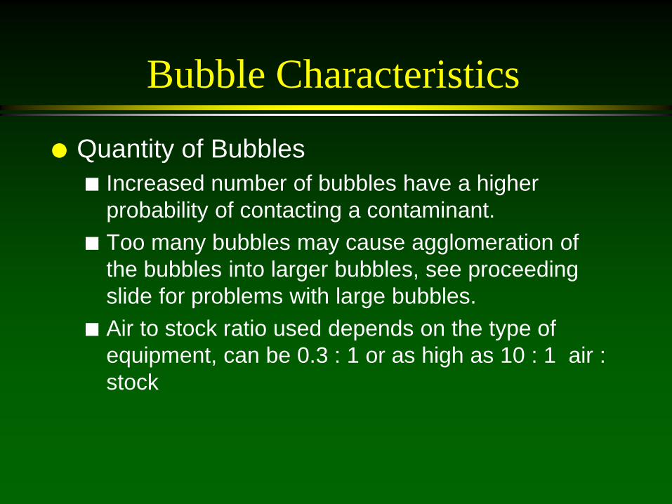
Quantity of Bubbles Increased number of bubbles have a higher
probability of contacting a contaminant. Too many bubbles may cause agglomeration of
the bubbles into larger bubbles, see proceeding slide for problems with large bubbles.
Air to stock ratio used depends on the type of equipment, can be 0.3 : 1 or as high as 10 : 1 air : stock
Process Conditions
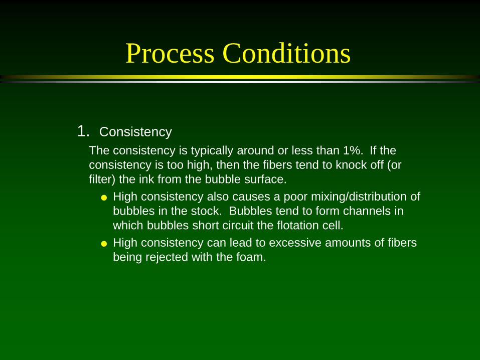
1. Consistency The consistency is typically around or less than 1%. If the
consistency is too high, then the fibers tend to knock off (or filter) the ink from the bubble surface.
High consistency also causes a poor mixing/distribution of bubbles in the stock. Bubbles tend to form channels in which bubbles short circuit the flotation cell.
High consistency can lead to excessive amounts of fibers being rejected with the foam.

Process Conditions
2. Foam Generation Foam is generated by adding a foaming agent to the stock
before the stock enters the flotation process. Too much foam causes excessive fiber losses, and increased
amounts of foam to destroy. Too little foam or an unstable foam will allow contaminants to fall
back into the stock and not be removed. The amount of foam is usually controlled by the flowrate of
foaming agent. 3. Flow Rate
Too high a flow rate through a flotation cell generates large turbulent forces which can detach inks from bubbles. It also can disturb the foam. The required production rate sets a minimum value on the flow rate.
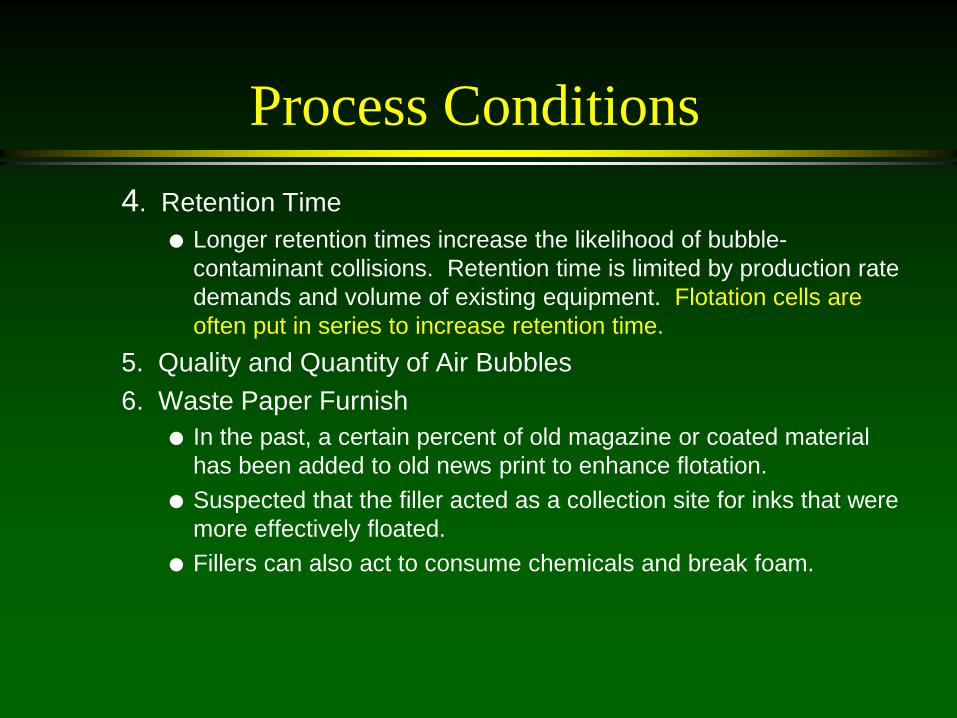
Process Conditions 4. Retention Time
Longer retention times increase the likelihood of bubble-contaminant collisions. Retention time is limited by production rate demands and volume of existing equipment. Flotation cells are often put in series to increase retention time.
5. Quality and Quantity of Air Bubbles 6. Waste Paper Furnish
In the past, a certain percent of old magazine or coated material has been added to old news print to enhance flotation.
Suspected that the filler acted as a collection site for inks that were more effectively floated.
Fillers can also act to consume chemicals and break foam.

Flotation Equipment
Equipment • Voith • Fiberprep • Sulzer • BC • Beloit • Shinhama • Kamyr • Wemco

Flotation Cell
Black Clawson Flotator
Feed
Foam
Accepts
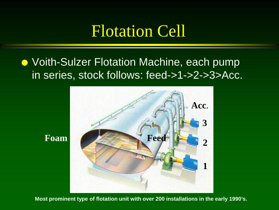
Flotation Cell
Voith-Sulzer Flotation Machine, each pump in series, stock follows: feed->1->2->3>Acc.
Feed Foam
Acc.
1
2
3
Most prominent type of flotation unit with over 200 installations in the early 1990’s.
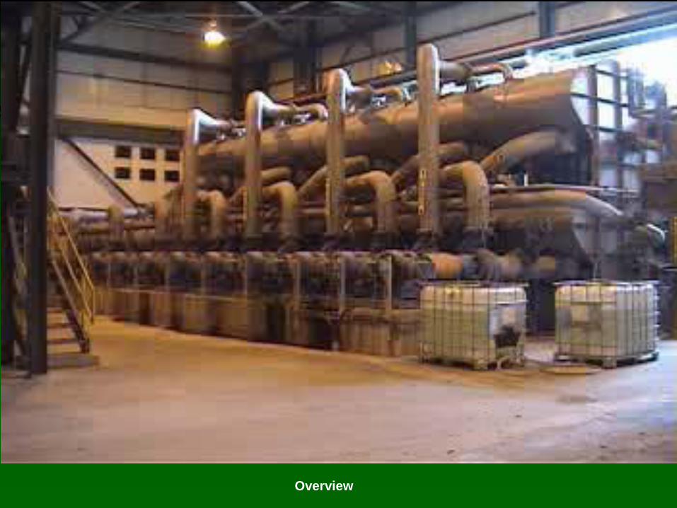
Overview

Trace Lines
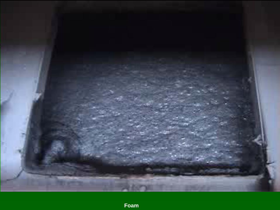
Foam

Flotation Cell
Lamort - Fiberprep Flotation Cell

Flotation Cell
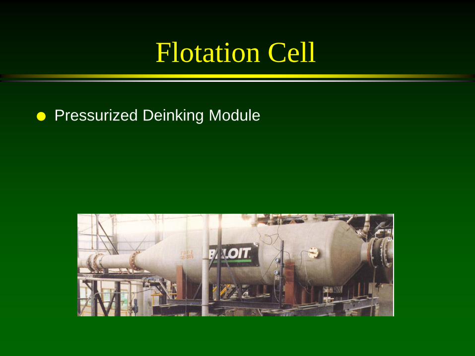
Flotation Cell
Pressurized Deinking Module

Major Parameters Impacting Flotation Efficiency
Particles: number, size, shape, density, surface chemistry, agglomeration
Bubble: type of gas, number, size, surface chemistry, nature (dispersed or dissolved)
Mixing: Nature, intensity, time Process Conditions: Recovered paper,
type/amt ink, type/amt ash, fiber characteristics, consistency, temp, retention time, cell design, pH, chemical environment, foam characteristics Secondary Fiber Recycling, Tappi Press, 1993
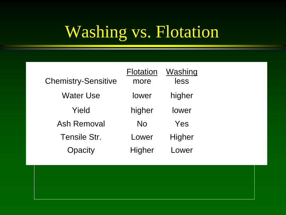
Washing vs. Flotation
Flotation WashingChemistry-Sensitive more less
Water Use lower higher
Yield higher lowerAsh Removal No YesTensile Str. Lower Higher
Opacity Higher Lower

Lecture:
Dispersion and kneading

Dispersion of Contaminants in Recovered Paper Stock
Definition: The use of mechanical action to decrease the particle size of contaminants and release the contaminants from the fiber surfaces (below, an example of pulp before and after dispersion).

Dispersion of Contaminants in Recovered Paper Stock
Contaminants: inks, toners, coatings, wax, bitumen, varnish, hot melts, glues
Dispersion assisted by heating, contaminants soften from 60 – 120 C
Visible size (40 microns) to sub-visible size
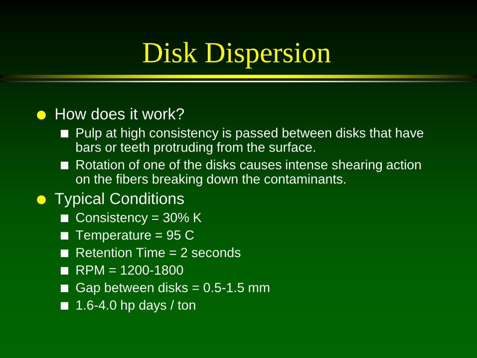
Disk Dispersion
How does it work? Pulp at high consistency is passed between disks that have
bars or teeth protruding from the surface. Rotation of one of the disks causes intense shearing action
on the fibers breaking down the contaminants. Typical Conditions
Consistency = 30% K Temperature = 95 C Retention Time = 2 seconds RPM = 1200-1800 Gap between disks = 0.5-1.5 mm 1.6-4.0 hp days / ton

Dispersion
Feed
Exit
Teeth Rotating Shaft

Dispersion Dispersing System:
Process stock is dewatered to 30%K
Clods of stock are broken in the breaker screw
Steam introduced into a heating screw to increase temperature to 85-120 C (above 120 C damages fibers)
Stock fed to dispersing unit
Stock is diluted and agitated for further processing

Screw press
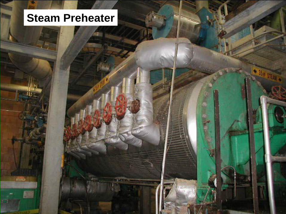
Steam Preheater

Dispersion Unit
Motor
Disperser
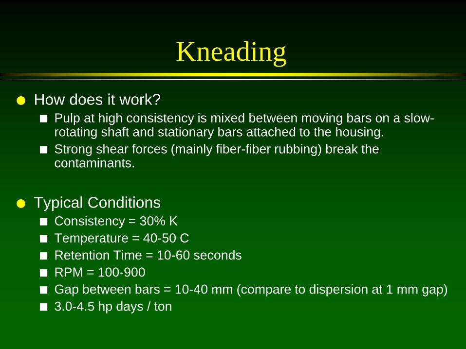
Kneading How does it work?
Pulp at high consistency is mixed between moving bars on a slow-rotating shaft and stationary bars attached to the housing.
Strong shear forces (mainly fiber-fiber rubbing) break the contaminants.
Typical Conditions
Consistency = 30% K Temperature = 40-50 C Retention Time = 10-60 seconds RPM = 100-900 Gap between bars = 10-40 mm (compare to dispersion at 1 mm gap) 3.0-4.5 hp days / ton
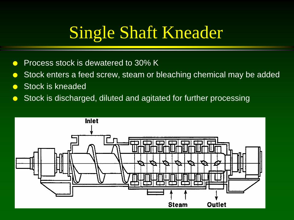
Single Shaft Kneader Process stock is dewatered to 30% K Stock enters a feed screw, steam or bleaching chemical may be added Stock is kneaded Stock is discharged, diluted and agitated for further processing

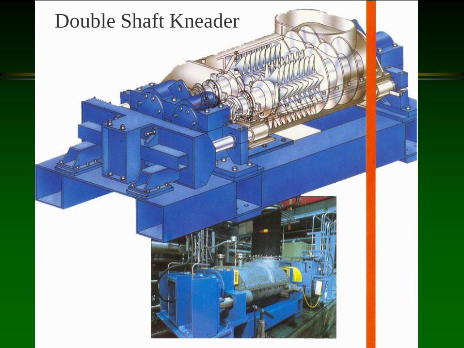
Double Shaft Kneader
Operation principles the same as the single shaft kneader
Contains two shafts rotating in different directions at slightly different speeds (20% difference in RPM)
The different speeds and directions of the shafts generate intense shearing action.
Double Shaft Kneader
Drawbacks to Kneading
Energy intensive: 3.0-4.5 hp day/ton High initial capital cost Requires thickening equipment Does not reduce sticky size (this may be
an advantage) Rotors can wear out (1-2 years)

Kneading vs. Dispersion
Dispersion KneadingMechanism Shear RubConsistency 30% 30%Temp. 95 50RPM 1200-1800 100-900Retent. Time 2 s 10-60 sGap, mm .5-1.5 10-40
Methods to decrease contaminant size.

Kneading vs. Dispersion
Effect Dispersion KneadingTappi Dirt Reduct. 75% 85%
Toner Reduct. yes betterStickies Reduct. better no effect
Fiber Cutting substantial noneFines Generation yes no
Methods to decrease contaminant size.

Lecture:
Bleaching

Bleaching
Bleaching is the chemical process applied to cellulosic materials to destroy chromophores, increasing the brightness and reducing color
Chemical reactions Oxidative, like peroxide Reductive, like Sodium hydrosulfite and
FAS
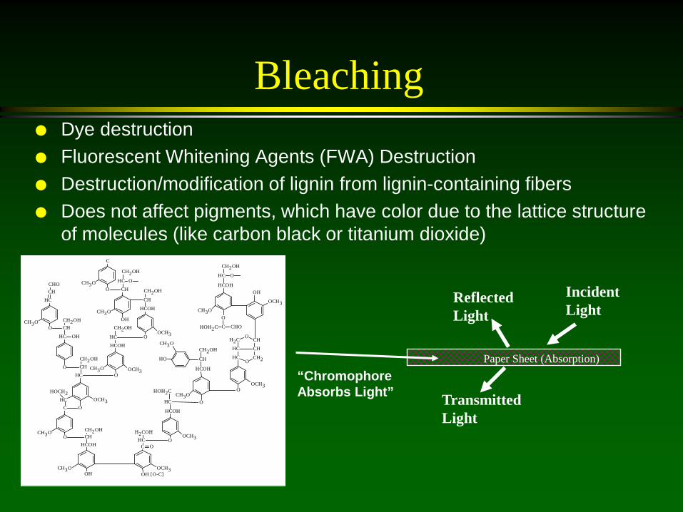
Bleaching Dye destruction Fluorescent Whitening Agents (FWA) Destruction Destruction/modification of lignin from lignin-containing fibers Does not affect pigments, which have color due to the lattice structure
of molecules (like carbon black or titanium dioxide)
Reflected Light
Incident Light
Transmitted Light
Paper Sheet (Absorption) CH3O
OCH3
CH2OH
O
CH
HCOH
CHOCHOH2C
O
CH3O
OCH3
HOH2C
O
HC
HCOH
OCH3
O
CH3O
HC
CH
O
CHO
OH
CH2OH
O
CH
HC
HC
CH
O
CH2OH
CH3O
HCOH
HC
O
CH2OH
OCH3
HOCH2
O
HCC
OCH3
CHC
OH [O-C]
CH2OH
OH
CHHCOH
CH3O H2COH
CH3O
HC
HC
O
H2C
CH2
OH
CH
CH
O
O
CH2OH
O
CH
HCOH
OCH3
HO
OCH3
HCOH
HC
O
CH2OH
CH3O
CH2OH
OH
HC
CH
CH3O
OCH3OO
C
“Chromophore Absorbs Light”

Brightness Measurement
Tappi Method T452 Specifies illuminating light at 45o to the sample and the reflected
light measuremement at 90o to the sample. Reflectance compared to magnesium oxide powder.
Units: % GE brightness
Technical Section, CPPA Method E1 Specifies the sample should be diffusely illuminated using a highly
reflecting integrating sphere. Reflected light measurement is at 90o to the sample. Reflectance is compared to absolute reflectance from an imaginary, perfectly reflecting diffusing surface.
Units: %ISO brightness
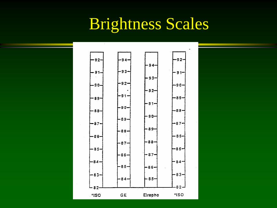
Brightness Scales
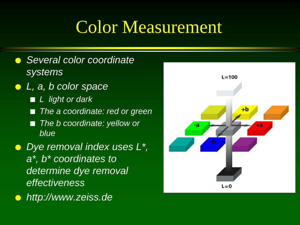
Color Measurement
Several color coordinate systems
L, a, b color space L light or dark The a coordinate: red or green The b coordinate: yellow or
blue
Dye removal index uses L*, a*, b* coordinates to determine dye removal effectiveness
http://www.zeiss.de

Fluorescence Measurement
Fluorescent whitening agents: ultraviolet energy is absorbed and re-emitted as visible light, increasing the brightness
To measure Fluorescence: Measure Normal Brightness with UV light shining on
sample Measure Brightness with UV filter that blocks the UV
light from shining on the sample If there is a difference in the two brightnesses, there is
FWA present

Paper Fibers
Cellulose and hemicellulose: white, colorless, do not absorb light
Lignin and extractives: have some color, especially when modified alkaline environments increase the color producing
groups in lignin – kraft chemical pulping – Semi-chemical pulping – Alkali used in ONP recycling to liberate inks and swell fibers
Dyes absorb light causing color and decreasing brightness
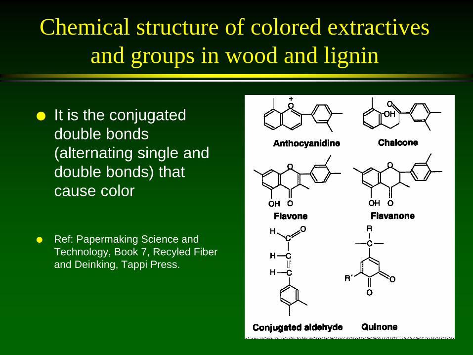
Chemical structure of colored extractives and groups in wood and lignin
It is the conjugated double bonds (alternating single and double bonds) that cause color
Ref: Papermaking Science and
Technology, Book 7, Recyled Fiber and Deinking, Tappi Press.

Dyes
Dyes and printing inks contribute to the color of fibers
It is the conjugated double bonds that cause color
=

Peroxide Bleaching (P)
The most important bleaching agent for mechanical recovered paper pulps
A clear, colorless liquid soluble in water at any concentration
HOO(-), perhydroxyl anion acts as a nucleophilic bleaching agent
H2O2 + H2O <-> HOO(-) + H3O(+) H2O2 + OH(-) <-> HOO(-) + H2O Oxidation reactions are irreversible

Peroxide Bleaching (P) The most
important bleaching agent for mechanical recovered paper pulps
Bleaches in a non delignifying manner by destroying the chromophore
Irreversible

Peroxide Bleaching
Sodium hydroxide (NaOH) is added to increase the perhydroxyl anion concentration, the active bleaching agent, HOO(-):
H2O2 + H2O <-> HOO(-) + H3O(+) H2O2 + OH(-) <-> HOO(-) + H2O

Peroxide Bleaching There is a non linear
relationship between H2O2 and bleaching performance
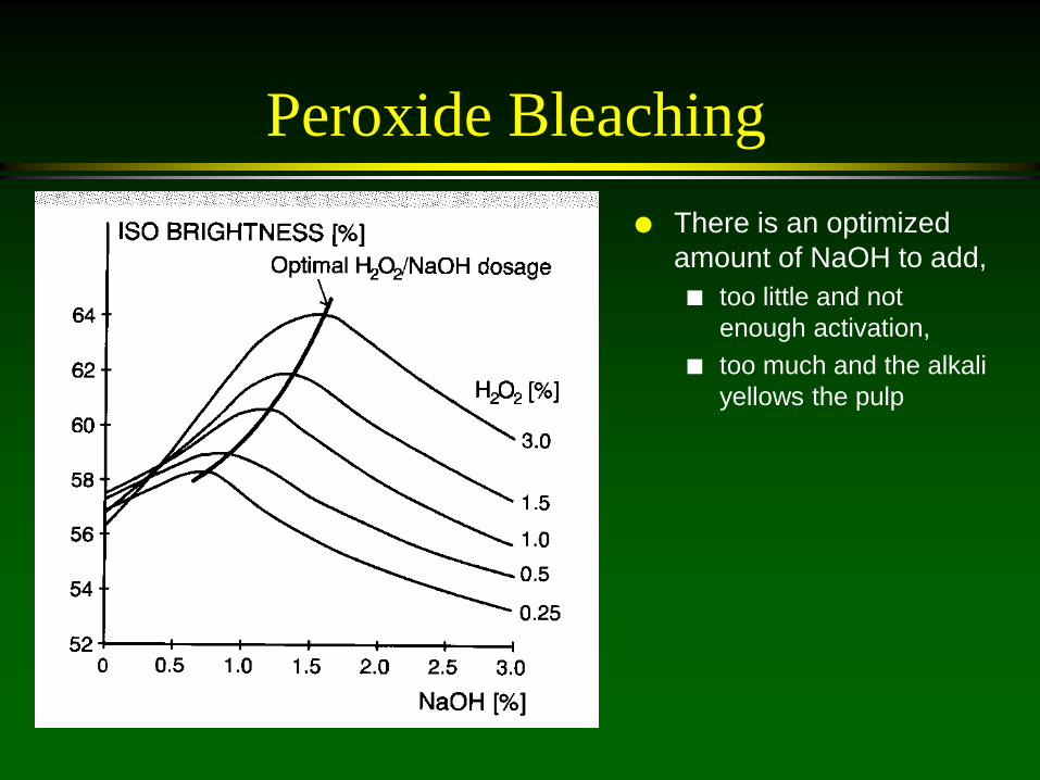
Peroxide Bleaching There is an optimized
amount of NaOH to add, too little and not
enough activation, too much and the alkali
yellows the pulp
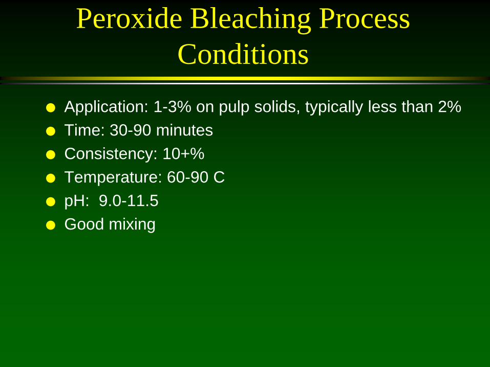
Peroxide Bleaching Process Conditions
Application: 1-3% on pulp solids, typically less than 2% Time: 30-90 minutes Consistency: 10+% Temperature: 60-90 C pH: 9.0-11.5 Good mixing
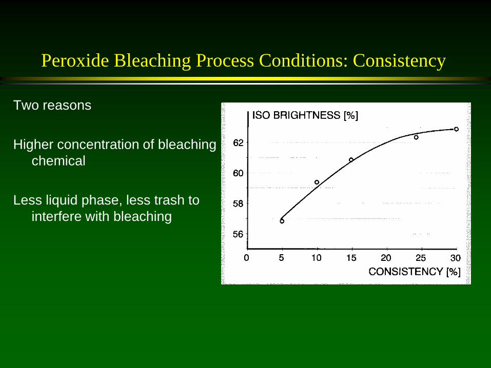
Peroxide Bleaching Process Conditions: Consistency
Two reasons Higher concentration of bleaching
chemical Less liquid phase, less trash to
interfere with bleaching

Peroxide Bleaching Heavy metal ions or enzymes (catalases) can
decompose the peroxide H202 -> 2H0* -> -> H2O + ½O2 Must stabilize the peroxide so it won’t form HO*:
Chelating agents: form complexes with the heavy metal ions to deactivate them
Most common: EDTA and DTPA
HO* does two bad things Its generation decreases the available
bleaching agent Can damage the cellulose in the fibers

Peroxide Bleaching: Decomposition of Peroxide
Causes of hydrogen peroxide decomposition Metal Ions Catalase:
– an enzyme produced by microorganisms and animal and vegetal cells to destroy peroxide which is toxic to the cell
– Must thermally denature the catalase by use of a biocide
Too High pH Too High temperature

Peroxide Bleaching: Chelating Agents
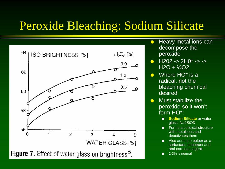
Peroxide Bleaching: Sodium Silicate Heavy metal ions can
decompose the peroxide
H202 -> 2H0* -> -> H2O + ½O2
Where HO* is a radical, not the bleaching chemical desired
Must stabilize the peroxide so it won’t form HO*: Sodium Silicate or water
glass, Na2SiO3 Forms a colloidal structure
with metal ions and deactivates them
Also added to pulper as a surfactant, penetrant and anti-corrosion agent
2-3% is normal

Peroxide Bleaching: Pulper
Not used as a true bleaching chemical in the pulper
Used to actually compensate for the darkening due to alkali in the pulper
Used to decolorize chromophores in groundwood generated by alkaline pH – prevents alkali darkening
Much of the contaminants in pulper render the bleaching action poor

Peroxide Bleaching: Disperser or Kneader
Used to compensate for graying of pulp due to the dispersion of the ink
Advantages Newly exposed fiber surfaces High consistency Good mixing High temperature
Disadvantages: Short residence time Too high a temperature can
degrade pulp Must use chelating agent as silicate
may build up on disks

Peroxide Bleaching: Tower More efficient than pulper Controlled reaction time Added to suction of medium
consistency pump to upflow tower
Caustic and silicate added to conveyor to medium consistency standpipe
Peroxide Bleaching: Post-bleaching
In the high density storage chest/tower Pulp is thickened and heated with steam to 60 C High shear mixer with chemicals added at one addition
point a preparation 1-3 hrs at 15 % consistency If market pulp, must be neutralized to pH of 7 to avoid
degradation
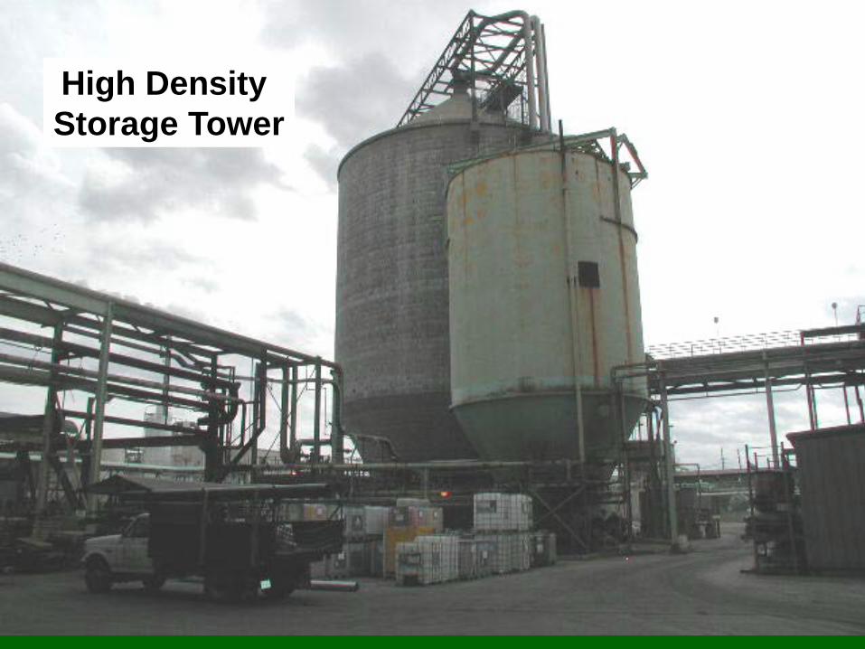
High Density Storage Tower

Dithionite Bleaching (Y) Common reductive bleaching chemical that can be
used for wood containing pulps Good at color stripping dyes Often called hydrohydrosulfite bleaching, which is the
incorrect term Na2S2O4 + H2O -> 2Na(+) + S2O4(-2) Sodium Hydrosulfite, Na2S2O4 Dithionate ion S2O4(-) is active Reductive reactions are reversible Oxygen decomposes the bleaching agents, need to
keep air out Calcium or magnesium precipitates the bleaching
agent, need to add chelant

Dithionite Bleaching (Y) Can be done in the pulper Added to disperser at 30% consistency, 80-100 C,
then diluted and pumped to an upflow tower Added to a MC pump feeding an up-flow tower at
10-12 % consistency
Application: 0.5-1.0% on pulp, 50-70 C, 30-90 min,pH =5.5-6.5 (acidic), consistency 3-5%, must be oxygen free

FAS Bleaching Formamidine Sulphinic Acid Low odor, crystalline powerful reducing agent Effective decolorizing for colored paper and carbonless
paper Excellent dye stripping Decomposes with oxygen Used in place of and is stronger than dithionite Slightly soluble in water Must be used soon or else decomposes in water

FAS Bleaching
Application: 0.3-1%, 30-90 min, 3.5-12 %K, 40-65C, pH=8-11, must be oxygen free
Need 1 part FAS to 0.5 parts NaOH Initial pH=9, Final pH=7-8 is optimum High filler content, calcium carbonate, requires
less NaOH Can be applied in a disperser or in post
bleaching
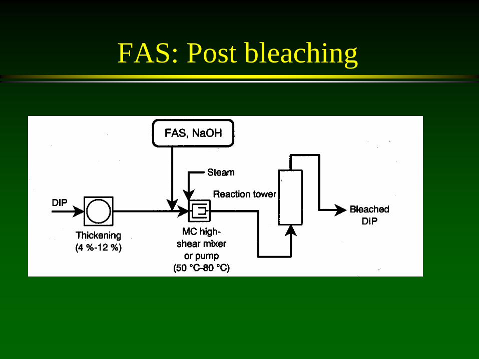
FAS: Post bleaching

FAS Disperser Bleaching

Bleaching Sequences: Single stages are not effective in reaching 80% ISO
brightness on MOW furnish Need two stages for MOW Variable incoming recovered paper requires multiple
stages Combination of oxidative followed by reductive bleaching
is most successful Must be careful to remove oxidative bleaching chemical
so it does not consume the reductive bleaching chemical Not common to do reductive bleaching first as the
reductive products are susceptible to being oxidized Common 2 stage processes: Peroxide-Peroxide,
Peroxide-dithionite, Peroxide-FAS

Lecture:
Treatment of waste streams from paper recycling operations

Paper Recycling Mill Waste
The generation of acceptable recycled pulp is accompanied with significant waste streams
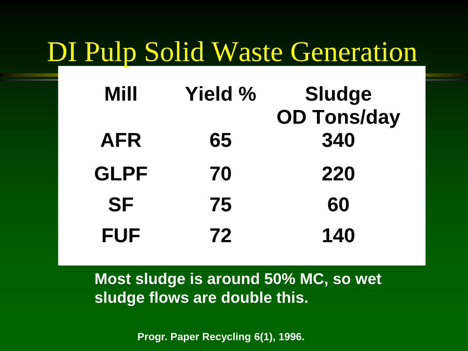
DI Pulp Solid Waste Generation Mill Yield % Sludge
OD Tons/dayAFR 65 340
GLPF 70 220SF 75 60
FUF 72 140
Progr. Paper Recycling 6(1), 1996.
Most sludge is around 50% MC, so wet sludge flows are double this.
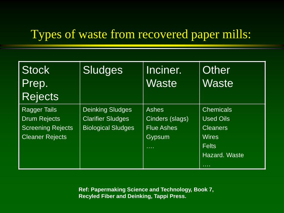
Types of waste from recovered paper mills:
Stock Prep. Rejects
Sludges Inciner. Waste
Other Waste
Ragger Tails Drum Rejects Screening Rejects Cleaner Rejects
Deinking Sludges Clarifier Sludges Biological Sludges
Ashes Cinders (slags) Flue Ashes Gypsum ….
Chemicals Used Oils Cleaners Wires Felts Hazard. Waste ….
Ref: Papermaking Science and Technology, Book 7, Recyled Fiber and Deinking, Tappi Press.

Amount of Rejects and Sludges for Production of Paper Grades
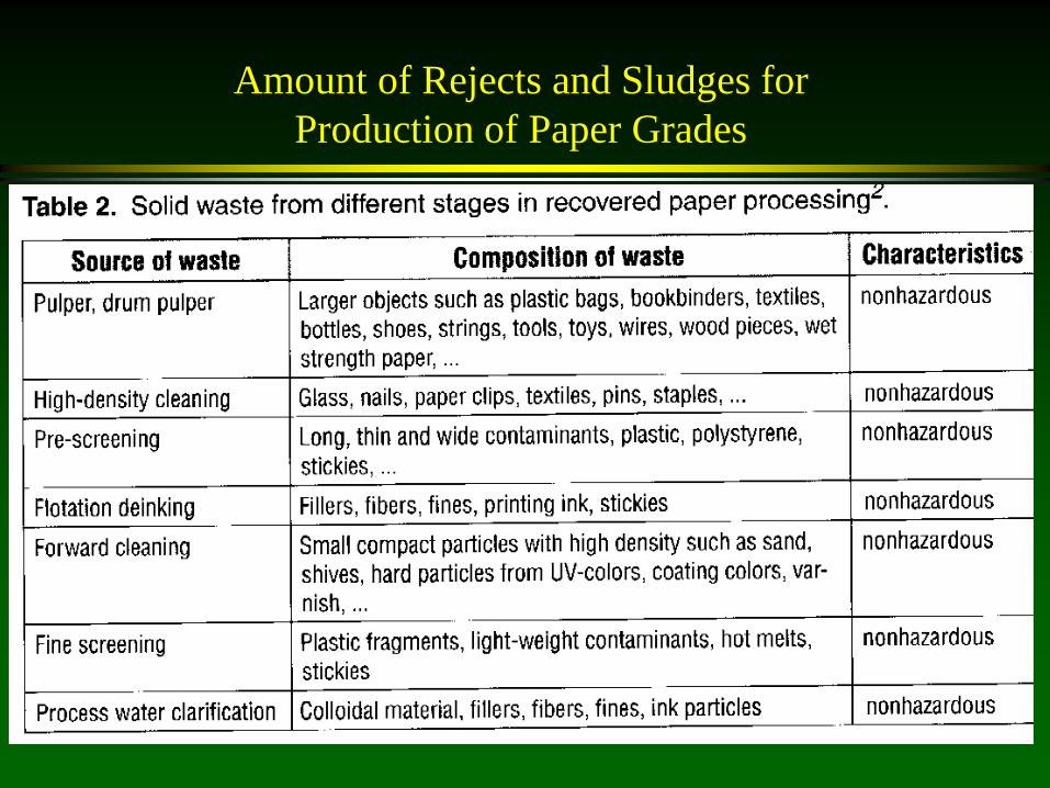
Amount of Rejects and Sludges for Production of Paper Grades
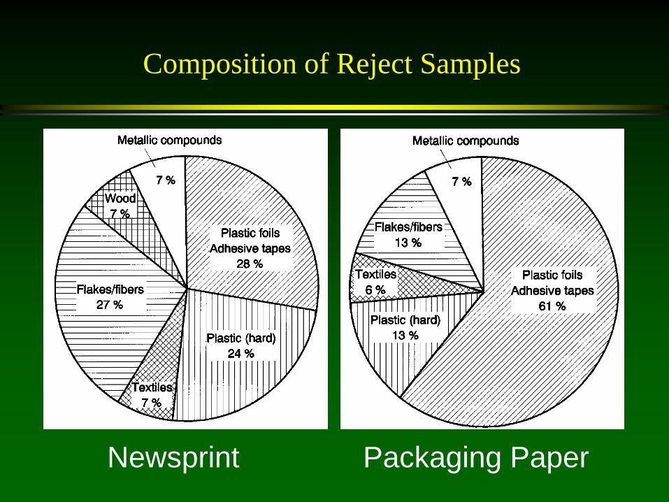
Composition of Reject Samples
Newsprint Packaging Paper

Composition of De-inking Sludge Samples
Printing Paper (Flotn) Tissue (Washing)

De-inking Sludges
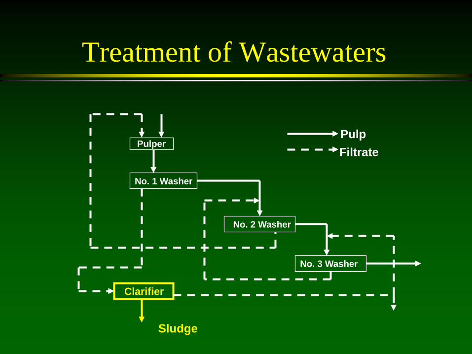
Treatment of Wastewaters
Pulper
No. 1 Washer
No. 2 Washer
No. 3 Washer
Clarifier
Pulp Filtrate
Sludge

Water Treatment
Re-use filtrates (often from thickening or washing process) to conserve water
Clarifier objective: take filtrate and make a sludge and a filtrate
Filtrate to Clarifier: 2000 ppm suspended solids Clarified water: 100 ppm suspended solids Sludge: 3-7% solids No change in colloidal or dissolved species
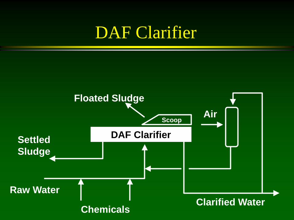
DAF Clarifier
DAF Clarifier
Clarified Water Raw Water
Chemicals
Settled Sludge
Air Floated Sludge
Scoop
Clarifier

Clarifier Rejects Scoop

DAF Clarifier
DAF = dissolved air flotation most common clarifier for recycling raw water is treated with chemicals to form flocs
of suspended solids tiny air bubbles are mixed with the water and
attach to the flocs the flocs rise to the surface and are scooped out some of the flocs settle to the bottom and are
also removed
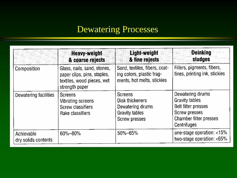
Dewatering Processes

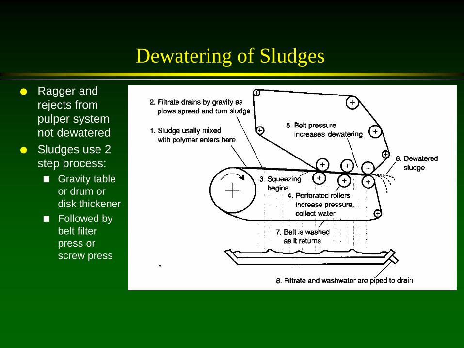
Dewatering of Sludges Ragger and
rejects from pulper system not dewatered
Sludges use 2 step process: Gravity table
or drum or disk thickener
Followed by belt filter press or screw press
Dewatering of Sludges Ragger and
rejects from pulper system not dewatered
Sludges use 2 step process: Gravity table
or drum or disk thickener
Followed by belt filter press or screw press
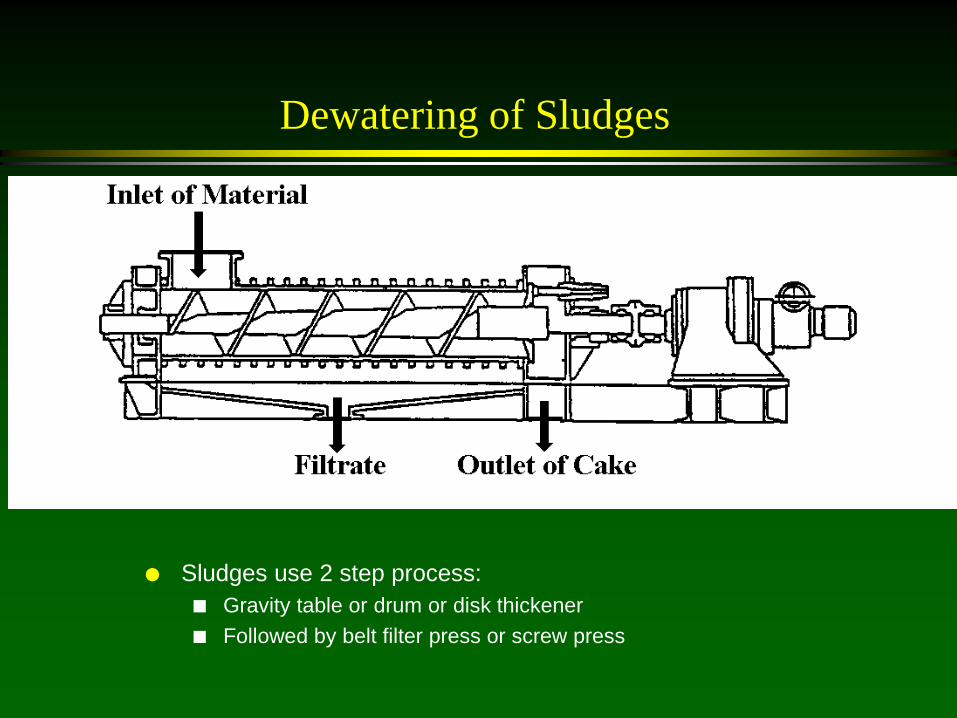
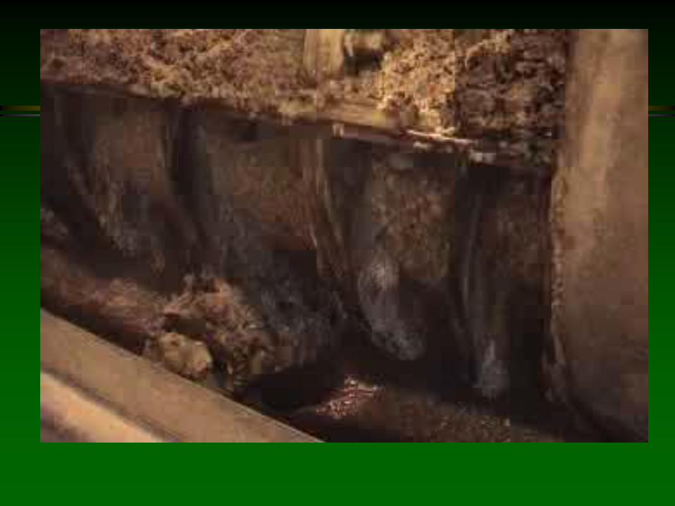
Dewatering of Sludges
Sludges use 2 step process:
Gravity table or drum or disk thickener Followed by belt filter press or screw press

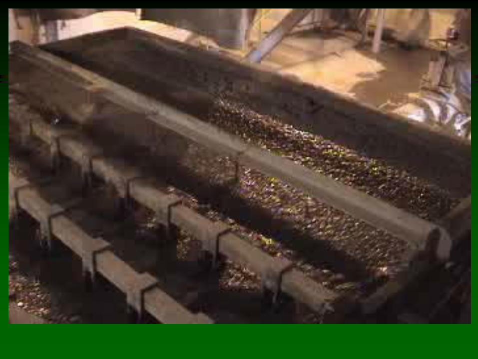
Screw Press
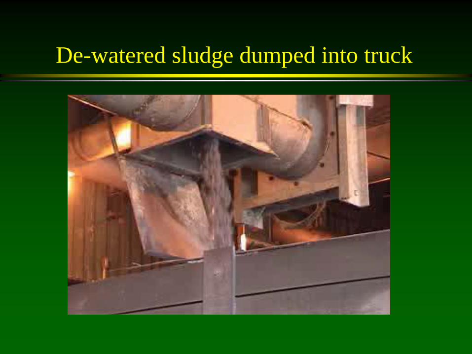
De-watered sludge dumped into truck

Sludge Final Fates:
Final disposition landfill incineration composting Cement, brick, concrete, mortar and lime
brick, road construction others

Example of Sludge Combustion Combustion:
Volume Reduction
Inert organics Immobilize
harmful material in ashes and slags
Generate energy
Increased interest: Increased cost
of fuel and purchased power
Landfill costs Environmental
regulations New
combustion techn. With flue gas cleaning

Summary: Paper Recycling Waste
Recycling Generates significant waste Many different types of waste
Rejects Sludge
Sludge from clarifier must be dewatered Several modes of disposal
Landfilling Incineration others
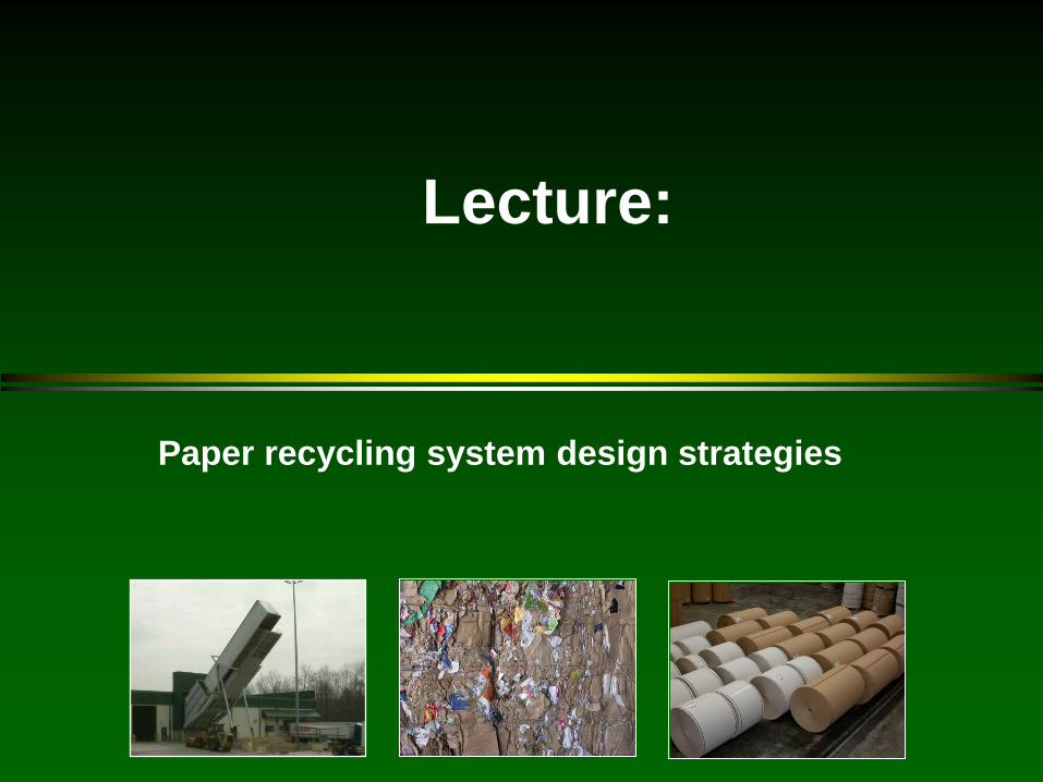
Lecture:
Paper recycling system design strategies

Paper Recycling Systems
Learning objectives Appreciate the strategies involved in designing a
recycle process Recognize the relative number and types of sub-
operations in each type of recycle process Understand rejects, sludge and water management
in a recycle system

Paper Recycling Operations: A Balancing Act
Production
Yield
Quality
Profit Safety Environment
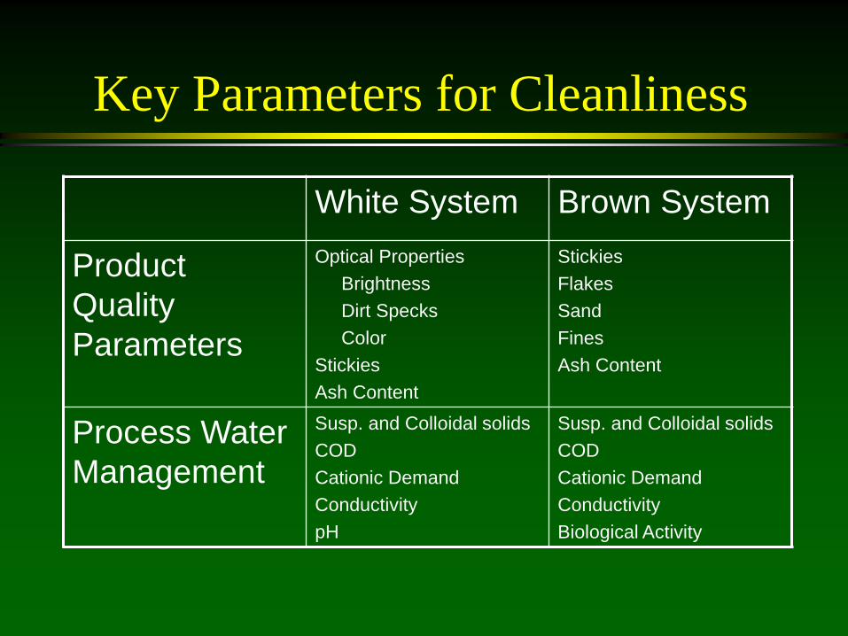
Key Parameters for Cleanliness
White System Brown System
Product Quality Parameters
Optical Properties Brightness Dirt Specks Color Stickies Ash Content
Stickies Flakes Sand Fines Ash Content
Process Water Management
Susp. and Colloidal solids COD Cationic Demand Conductivity pH
Susp. and Colloidal solids COD Cationic Demand Conductivity Biological Activity

Amount of Rejects and Sludges for Production of Paper Grades

Recovered Paper Prices
0
50
100
150
200
250
300
350
400
450
1970 1975 1980 1985 1990 1995 2000 2005
Year
$/to
n
Sorted White LedgerONPOCCMixed Paper

System Design Considerations There are several objectives of a recycling mill
Profitable Meet product quality specifications Environmentally acceptable Reliable and safe operations
There are many variables that can be adjusted to meet the objectives. Type of wastepaper furnish Type and number of unit operations Order of operations
There are several variables that impact a recycle mill that are largely uncontrollable Price and availability of raw materials Price of products Changing governmental regulation
The optimization of this multiple-input, multiple-objectives problem is non-trivial -- in the 1990’s several deinking plants went out of business and continue to put pressure on the recycling industry

Other System Design Considerations Raw Material
availability cost suitability for process Usable fiber content
Product Desired optical properties strength properties
Environmental Constraints Solid waste Water effluents Gas effluents
Space Requirements Capital Costs Operating Costs

General Process Strategies
The following concepts or strategies are often implemented in system design : Keep out unremovable contaminants from the process Ensure that contaminants are well separated from the fibers Remove contaminants early in the process Keep contaminants large to enhance removal Repeat inefficient unit operations Save fiber by cascading unit operations Save water by using counter current operations and by
clarifying the water effectively Avoid excessive changes in consistency

Major Recycling Systems
Can be categorized by the products they produce Packaging Materials
– Typically, OCC materials are recycled back into linerboard, medium, tube stock, and solid board products
– Mixed waste can be used in lower quality applications Newsprint
– Old newspapers and magazines are converted into newsprint Tissue
– Bleached printing and writing wastes are converted into tissue – Wood containing papers can be used for lower quality applications
Printing and Writing Materials – Bleached printing and writing wastes are converted into new printing
and writing grades
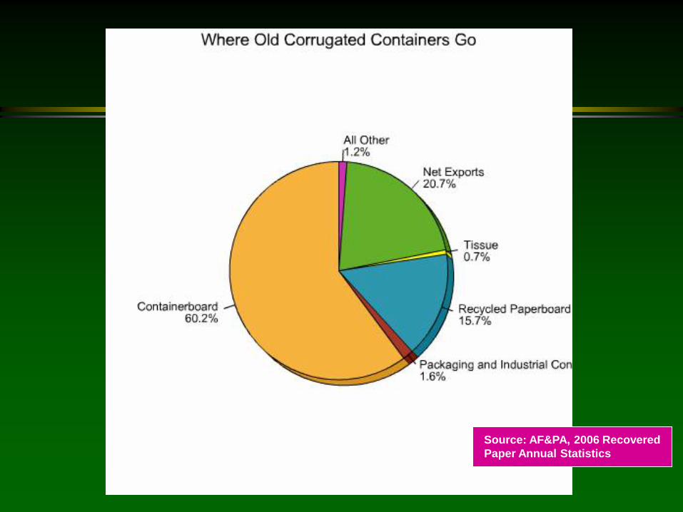
Source: AF&PA, 2006 Recovered Paper Annual Statistics
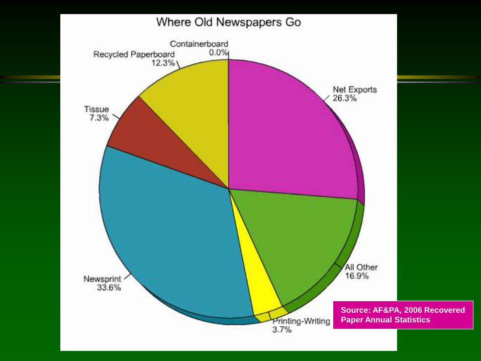
Source: AF&PA, 2006 Recovered Paper Annual Statistics

Source: AF&PA, 2006 Recovered Paper Annual Statistics

Lecture:
Paper recycling systems
Production of Newsprint

ONP-OMG Recycling
Used to produce recycled newsprint
May have batch, continuos tub or drum pulping
Note the strategy: 1st remove coarse
contaminants 2nd remove smaller
contaminants, deinking 3rd disperse unremoved
contaminants Often bleaching is used to
increase brightness Problems with stickies may
be caused by OMG
Ref: Secondary Fiber Recycling, Tappi, 2003.
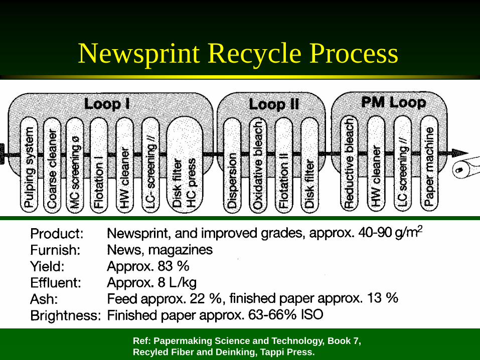
Newsprint Recycle Process
Ref: Papermaking Science and Technology, Book 7, Recyled Fiber and Deinking, Tappi Press.
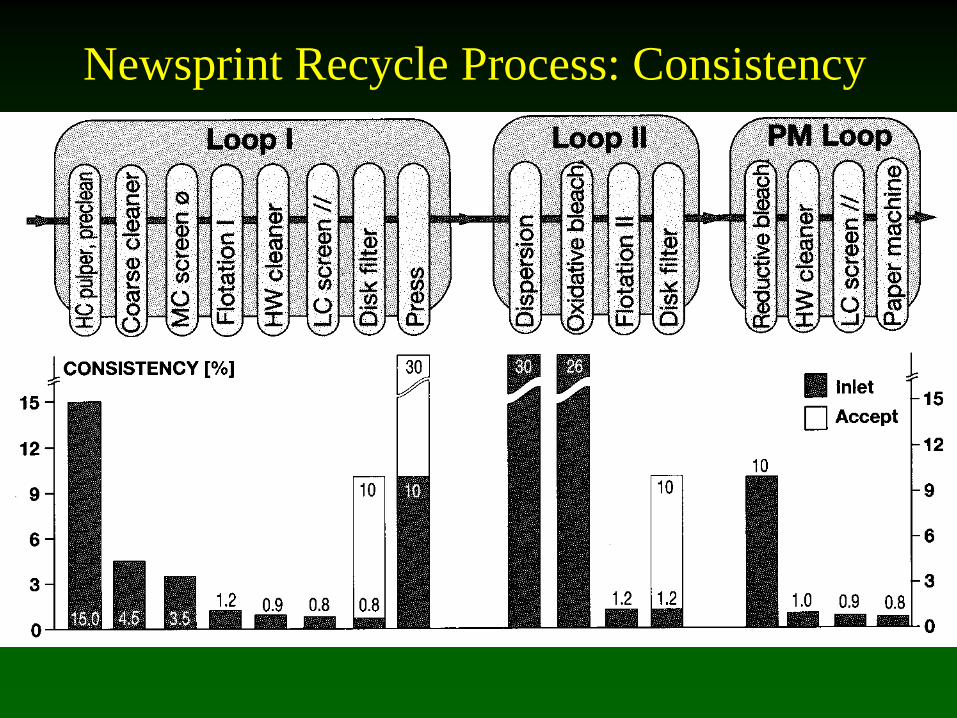
Newsprint Recycle Process: Consistency

Newsprint Recycle Process: Ash

Newsprint Recycle Process: Stickies

Newsprint Recycle Process: Dirt Speck Area

Newsprint Recycle Process: Brightness

Newsprint Recycle Process: Rejects, Sludge Water Systems
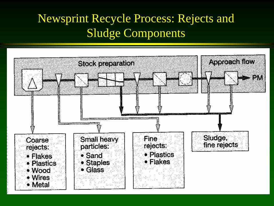
Newsprint Recycle Process: Rejects and Sludge Components
Production of High-Grade Printing and Writing Grades

Deinking of Printing Grades for
Printing/Writing
Used to produce new printing and writing grades
May use mixed or sorted waste ($ vs production trade-off)
Note the strategy: 1st remove coarse
contaminants 2nd remove smaller
contaminants, deinking 3rd disperse unremoved
contaminants 4th bleach to high
brightness Most complex system to
produce highest standard pulp
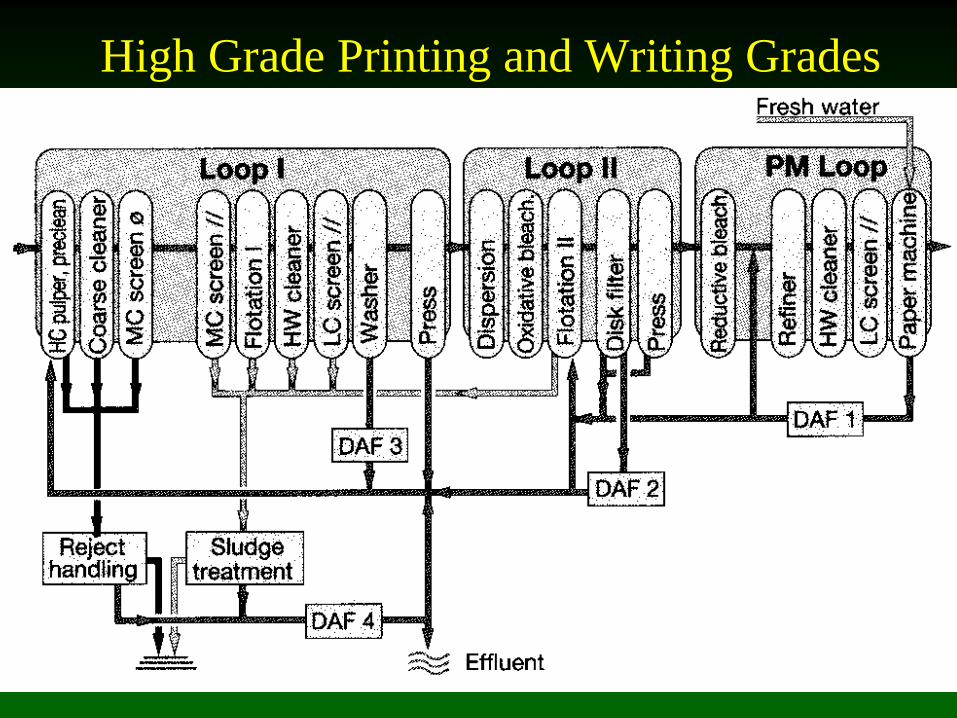
High Grade Printing and Writing Grades
Production of Tissue Grades

Deinking of Printing-Writing Grades for Tissue
Use sorted or non-sorted office waste to make tissue
For tissue making, filler level must be low for creping (1-1.5%) (see 2 stages of washing)
Yield can be as low as 60% Depending on quality of
tissue, brightness and dirt count also important
Lower grade tissue pulp production omits 1 stage of cleaners, bleaching and washing. May also omit flotation.
Wastepaper
High Consistency Pulper High Density Cleaning
Coarse Screening (Holes) Cleaning
Fine Screening (slots)
Washing I Thickening Dispersion
Bleaching (Oxidative)
Flotation Washing II Cleaning
Fine screening
Storage
Ref: Tappi deinking short course, 1995.
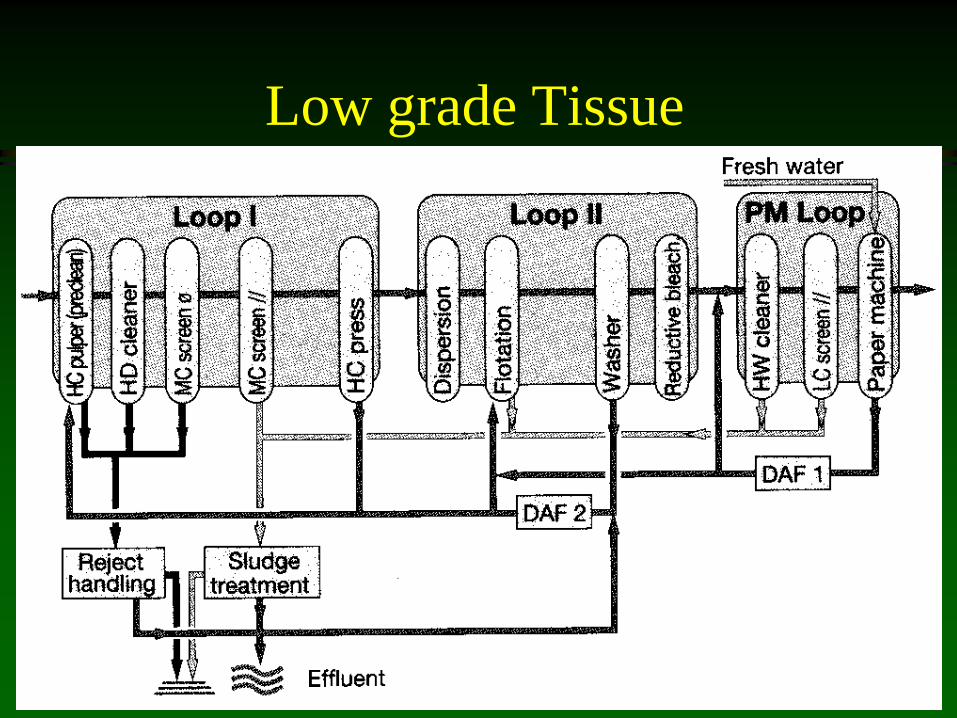
Low grade Tissue
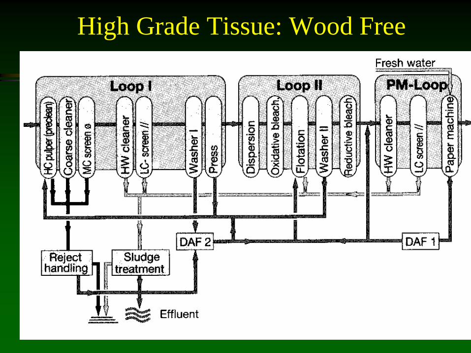
High Grade Tissue: Wood Free
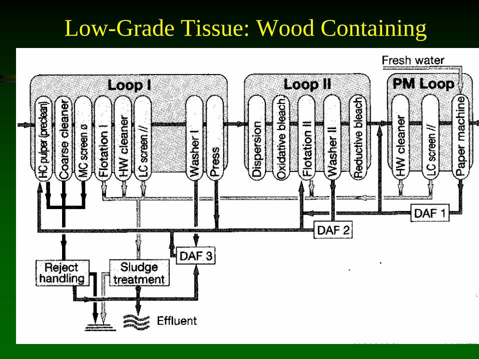
Low-Grade Tissue: Wood Containing

Production of Packaging Grades
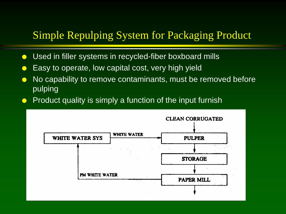
Simple Repulping System for Packaging Product
Used in filler systems in recycled-fiber boxboard mills Easy to operate, low capital cost, very high yield No capability to remove contaminants, must be removed before
pulping Product quality is simply a function of the input furnish

Crude Cleaning System for Packaging Product
Used to produce liner,
medium or tube stock Simple, high yield
process Ability to remove only
coarse contaminants Often used with a
continuous pulper

Multi-ply Board Packaging Product
Folding Boxboard Stiff, have plybond
strength, clean on outside Top layer can be bleached
chemical pulp or de-inked white grade
Underliner can be de-inked wood containing pulp
Filler layer has mixed waste Back layer uses kraft
unbleached pulp Quality indicated by
number, 1 highest quality Excess water from each
loop goes to inferior layer
Underliner,3
Filler, 4
Top Liner, 1
Back Liner,2
Outside of box, visible to customer
Inside of box, appearance not so important
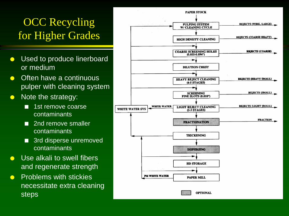
OCC Recycling for Higher Grades
Used to produce linerboard or medium
Often have a continuous pulper with cleaning system
Note the strategy: 1st remove coarse
contaminants 2nd remove smaller
contaminants 3rd disperse unremoved
contaminants Use alkali to swell fibers
and regenerate strength Problems with stickies
necessitate extra cleaning steps

Test Liner Production
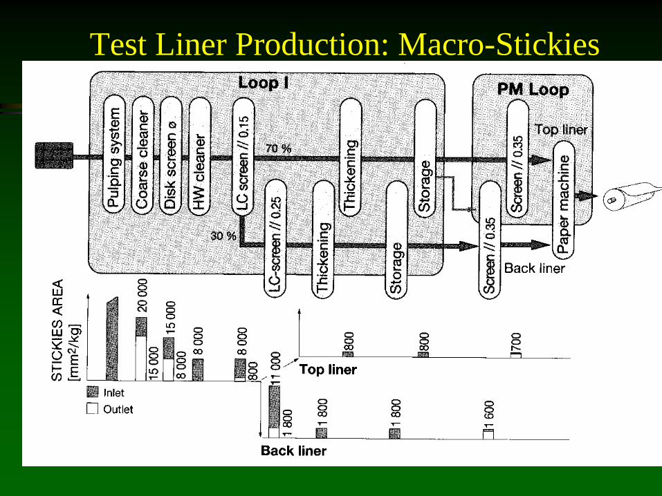
Test Liner Production: Macro-Stickies
Paper Recycling Systems: Summary Learning objectives
Appreciate the strategies involved in designing a recycle process
– Cleanliness/strength, production rate, yield Recognize the relative number and types of sub-operations in
each type of recycle process – Depends on the quality of product and the incoming raw
material – Need different operations to deal with inks, large junk, stickies,
fillers and brightness Understand rejects, sludge and water management in a
recycle system – Counter-current flow water-pulp to improve quality – Thickening to isolate water loops – Large rejects easily drained – Sludges are dewatered and pressed
Lecture:
Cost to produce deinked pulp

Cost of Deinked Pulp (DIP)
System MOW to deinked, bleached pulp (DIP) Flotation (2), washing, oxidative bleaching,
complementary processes Produce 200 ODTPD Yield = 67%
Total Capital Cost Installed= $42 MM $6 MM/yr depreciation for 7 years MOW Cost =$220/ton delivered

High Grade Printing and Writing Grades
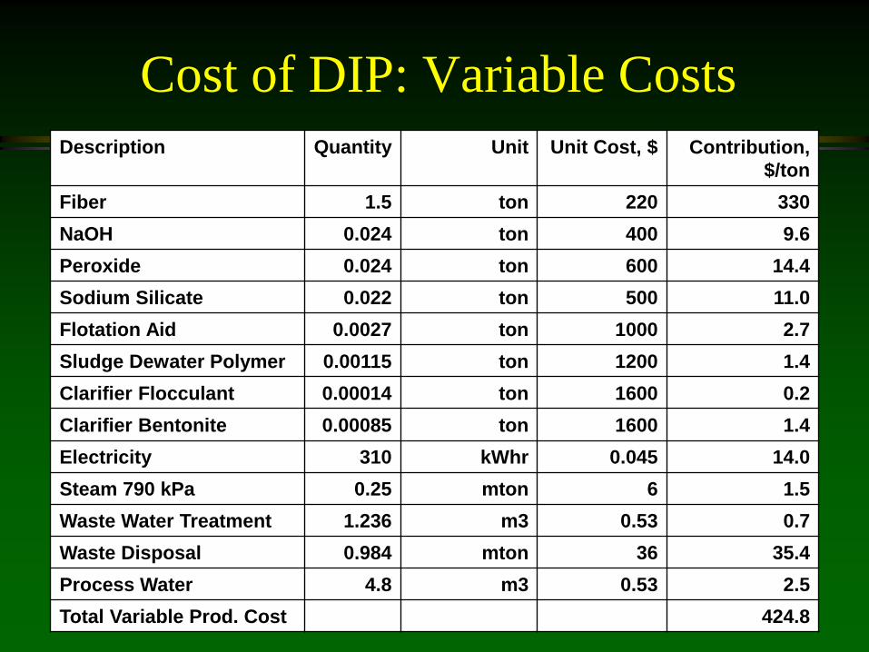
Cost of DIP: Variable Costs
Description Quantity Unit Unit Cost, $ Contribution, $/ton
Fiber 1.5 ton 220 330
NaOH 0.024 ton 400 9.6
Peroxide 0.024 ton 600 14.4
Sodium Silicate 0.022 ton 500 11.0
Flotation Aid 0.0027 ton 1000 2.7
Sludge Dewater Polymer 0.00115 ton 1200 1.4
Clarifier Flocculant 0.00014 ton 1600 0.2
Clarifier Bentonite 0.00085 ton 1600 1.4
Electricity 310 kWhr 0.045 14.0
Steam 790 kPa 0.25 mton 6 1.5
Waste Water Treatment 1.236 m3 0.53 0.7
Waste Disposal 0.984 mton 36 35.4
Process Water 4.8 m3 0.53 2.5
Total Variable Prod. Cost 424.8
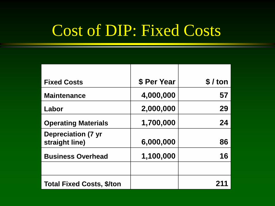
Cost of DIP: Fixed Costs
Fixed Costs $ Per Year $ / ton
Maintenance 4,000,000 57
Labor 2,000,000 29
Operating Materials 1,700,000 24 Depreciation (7 yr straight line) 6,000,000 86
Business Overhead 1,100,000 16
Total Fixed Costs, $/ton 211

Cost of DIP: ROI
Total Costs, $/ton produced 636
Total Costs per year, $ 44,532,716 Selling Price of ton DIP, $/ton 600 Income, $/yr 42,000,000 Profit before taxes, $ -2,532,716 Taxes (25%) -399,537 Profit after taxes, $ -2,133,179
ROI (%) Slightly
negative!

Lecture:
Automated Image Analysis of Paper to Detect Contaminants
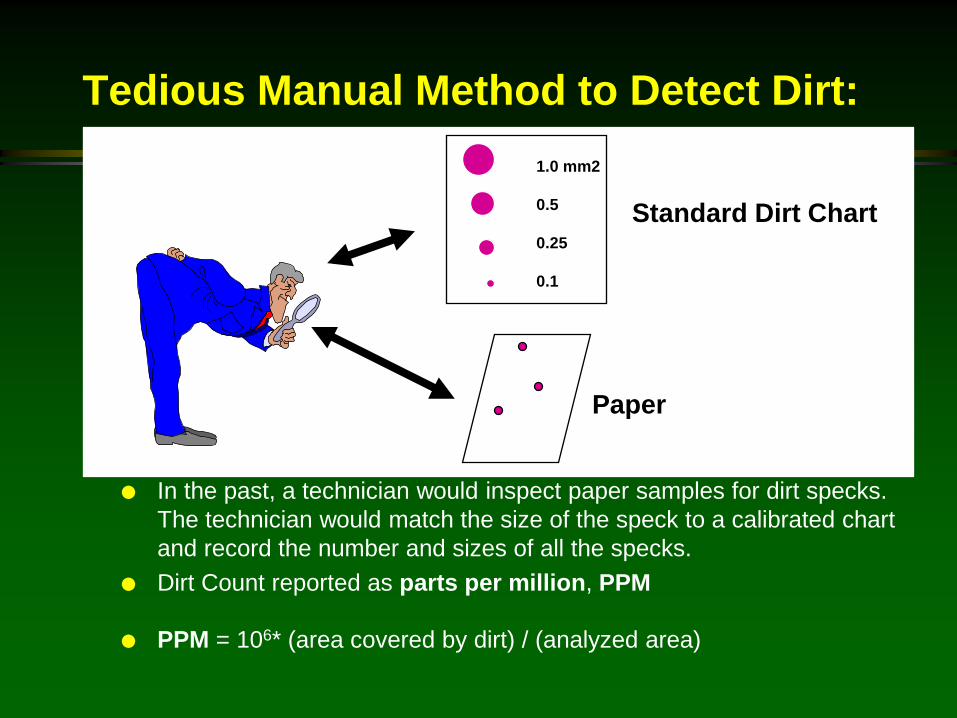
Tedious Manual Method to Detect Dirt:
In the past, a technician would inspect paper samples for dirt specks. The technician would match the size of the speck to a calibrated chart and record the number and sizes of all the specks.
Dirt Count reported as parts per million, PPM
PPM = 106* (area covered by dirt) / (analyzed area)
Paper
1.0 mm2 0.5 0.25 0.1
Standard Dirt Chart

Tappi Dirt Estimation Chart (mm2)
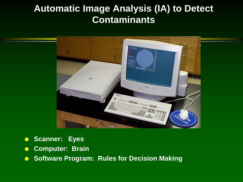
Automatic Image Analysis (IA) to Detect Contaminants
Scanner: Eyes Computer: Brain Software Program: Rules for Decision Making

Scanners digitize an image; the image is broken down into an array of pixels The size of the pixels depends on the resolution Resolution often reported as dots per inch (DPI) 600 dots per inch square is equal to a square with edge of 0.04 mm or area of
.018 mm2 The smallest size human sight can detect is an object with 0.05 mm longest
axis
IA: How it works
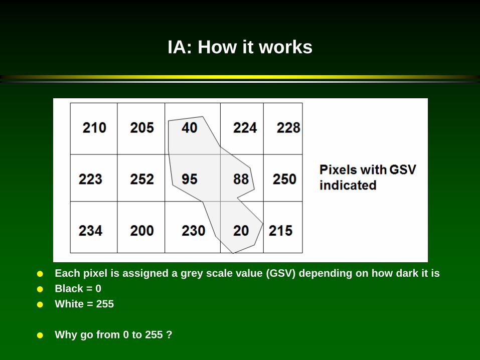
Each pixel is assigned a grey scale value (GSV) depending on how dark it is Black = 0 White = 255
Why go from 0 to 255 ?
IA: How it works

A threshold GSV is input into the computer by the operator If pixel GSV < threshold GSV computer recognizes it as contaminant If pixel GSV > threshold GSV computer recognizes it as clean paper
IA: How it works
0 GSV of pixels 255
# of pixels of that GSV
Pixels Assigned as Contaminant
Pixels assigned as paper
Threshold GSV
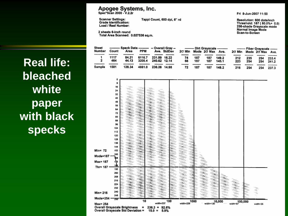
Real life: bleached
white paper
with black specks

Computer groups adjacent pixels with GSV < threshold together and then can determine size of dirt specks and total area covered by dirt and PPM
IA: How it works
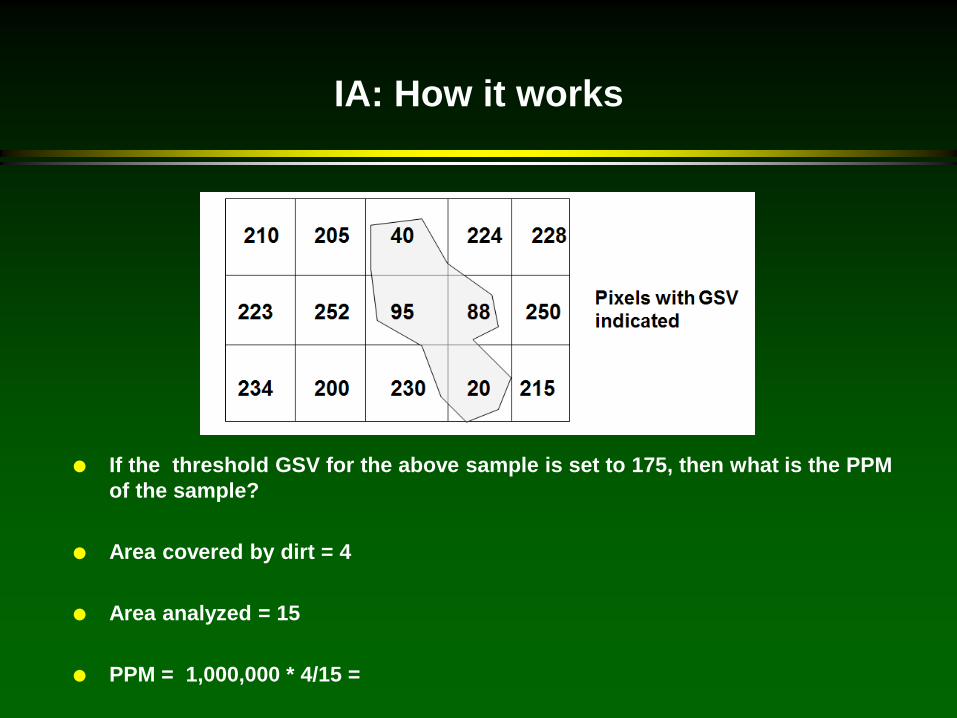
If the threshold GSV for the above sample is set to 175, then what is the PPM of the sample?
Area covered by dirt = 4
Area analyzed = 15
PPM = 1,000,000 * 4/15 =
IA: How it works
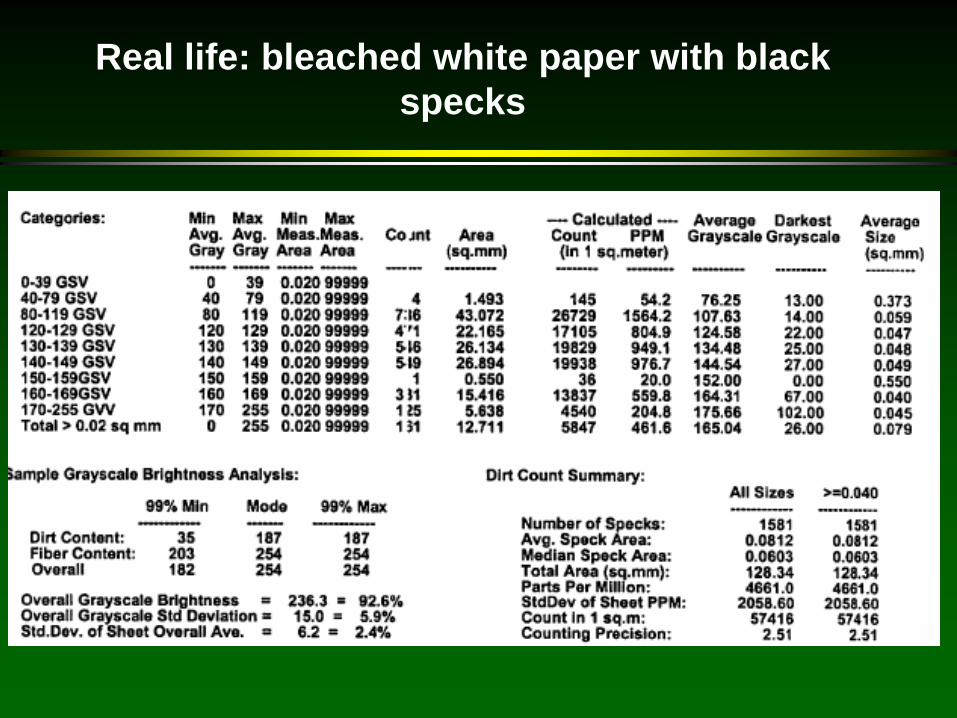
Real life: bleached white paper with black specks

Real life: bleached white paper with black specks
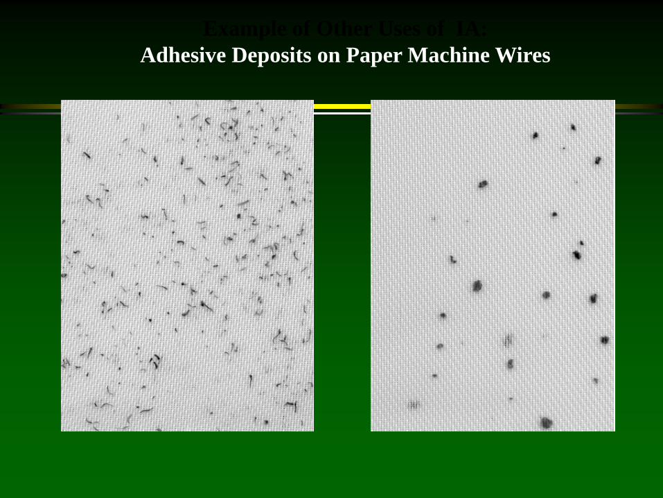
Example of Other Uses of IA: Adhesive Deposits on Paper Machine Wires

Following slides did not appear in presentations.
Left them here to not lose them.
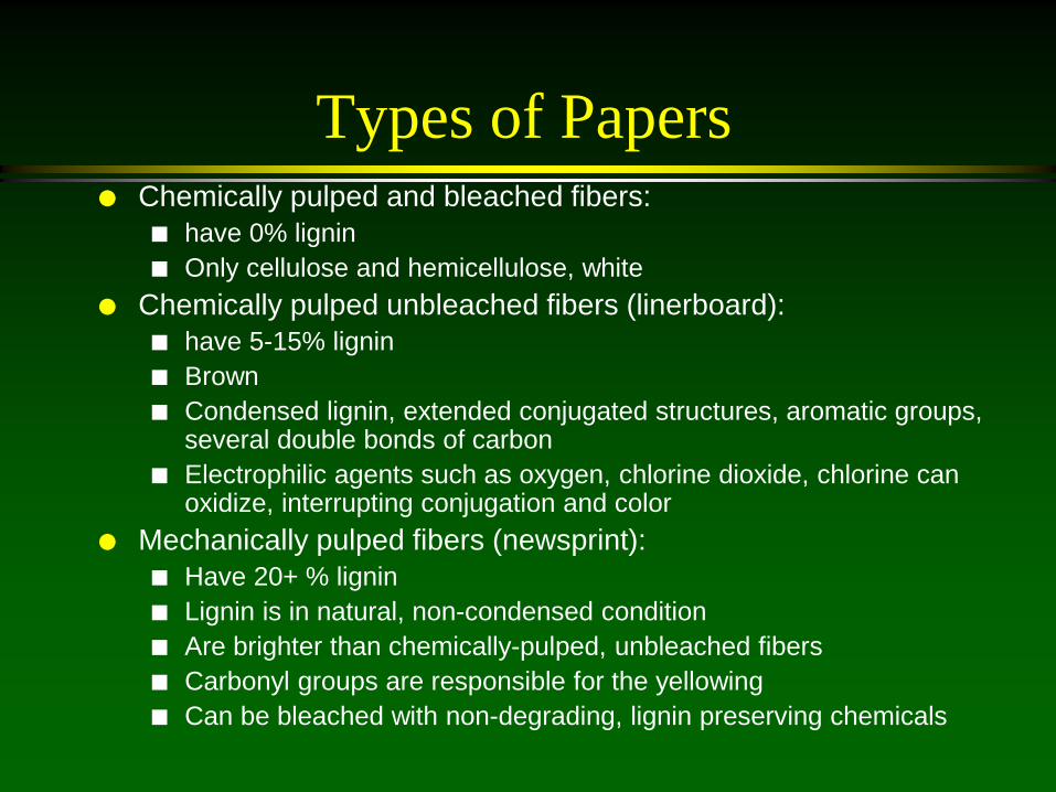
Types of Papers Chemically pulped and bleached fibers:
have 0% lignin Only cellulose and hemicellulose, white
Chemically pulped unbleached fibers (linerboard): have 5-15% lignin Brown Condensed lignin, extended conjugated structures, aromatic groups,
several double bonds of carbon Electrophilic agents such as oxygen, chlorine dioxide, chlorine can
oxidize, interrupting conjugation and color Mechanically pulped fibers (newsprint):
Have 20+ % lignin Lignin is in natural, non-condensed condition Are brighter than chemically-pulped, unbleached fibers Carbonyl groups are responsible for the yellowing Can be bleached with non-degrading, lignin preserving chemicals

Bleaching
If the color is due to conjugated carbonyl groups, as in mechanical fibers, lignin preserving chemicals should be used Peroxide, dithionate, FAS
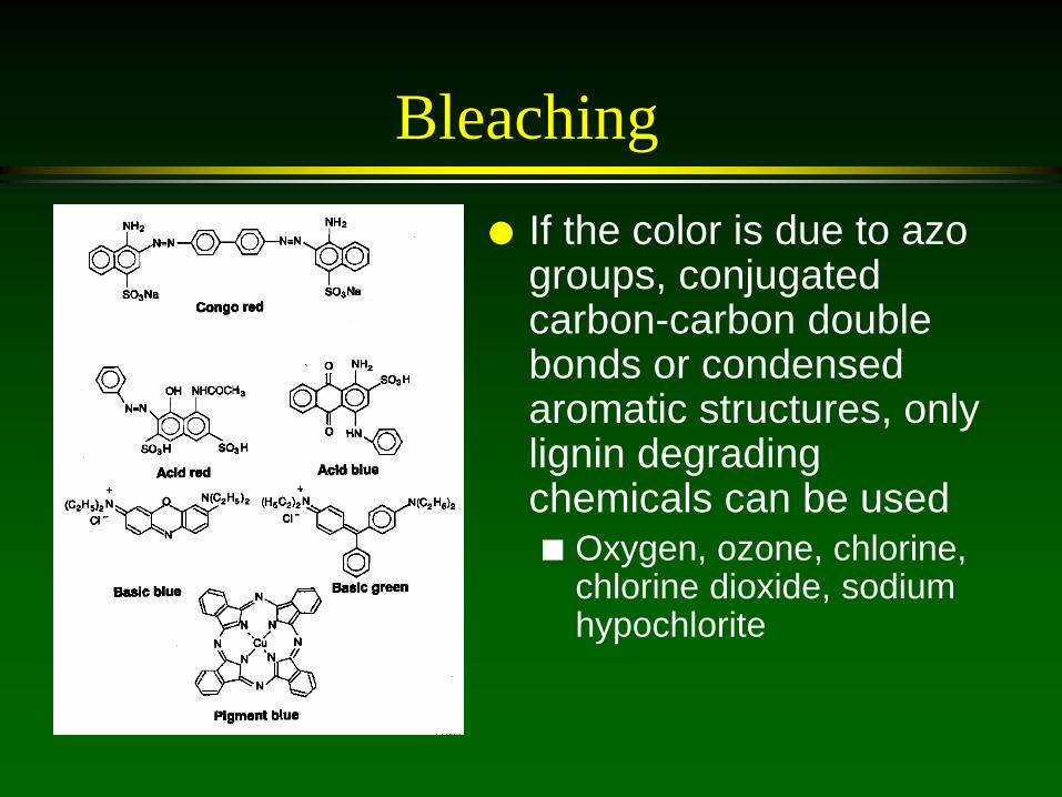
Bleaching If the color is due to azo
groups, conjugated carbon-carbon double bonds or condensed aromatic structures, only lignin degrading chemicals can be used Oxygen, ozone, chlorine,
chlorine dioxide, sodium hypochlorite
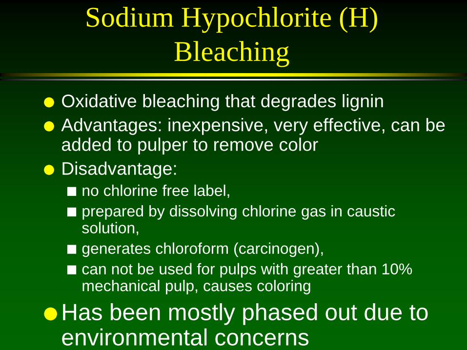
Sodium Hypochlorite (H) Bleaching
Oxidative bleaching that degrades lignin Advantages: inexpensive, very effective, can be
added to pulper to remove color Disadvantage:
no chlorine free label, prepared by dissolving chlorine gas in caustic
solution, generates chloroform (carcinogen), can not be used for pulps with greater than 10%
mechanical pulp, causes coloring
Has been mostly phased out due to environmental concerns

Sodium Hypochlorite (H) Bleaching
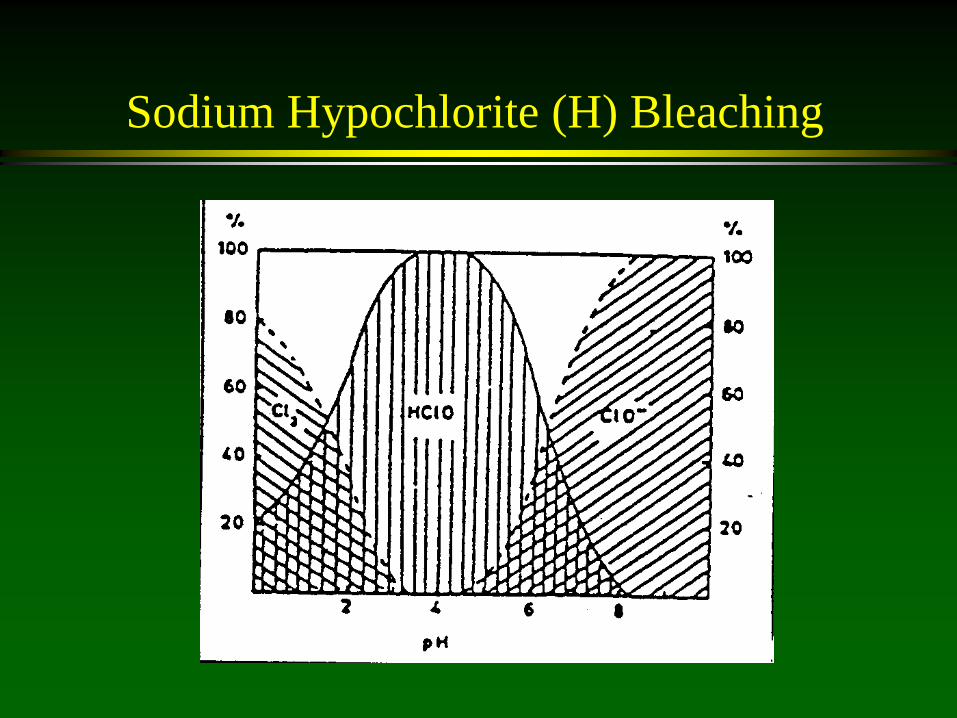
2NaOH + Cl2 -> NaOCl +NaCl+H2O NaOCl is sodium hypochlorite HOCl H(+) + ClO(-), pKa =7.5 Need pH greater than 9.5 for ClO- If pH 6-7 hypochlorous acid HOCl, which
attacks and degrades cellulose If pH less than 3 generate chlorine gas, Cl2
Sodium Hypochlorite (H) Bleaching
Sodium Hypochlorite (H) Bleaching
Application: 0.5-2.5% on pulp Time, 30-90 min Consistency: 3-12% Temperature: 35-70 C pH=9.5-11.0

Chlorine Dioxide Bleaching (D) Oxidative bleaching with excellent color
stripping and large brightness gains Disadvantages: no chlorine free label Process Conditions
Application: 0.2-1.0% on pulp Time: 60-180 minutes Consistency: 10-15% Temp: 55-70 C pH: 6.5-9.5, with 6.0 optimum

Oxygen Bleaching (O) Oxidative bleaching that improves brightness, lowers
chemical costs, removes color, detackifies stickies Disadvantages: will not tolerate mechanical pulps, need
pressurized vessel of 60-115 psig Oxygen produces radicals that degrade lignin and also
form peroxide which reacts with the chromophores Only system is Oxypro, patented by Air Products Conditions
1.0 % on pulp application, 60 min, 10-15 %K, 85-95 C, 1.0 % H2O2, 0.7-1.0 % NaOH, Na2SiO3 1.5-2.0%, DTPA 0.2%, pressure 60 psig
Ozone Bleaching (Z) Destroys dyes and optical whiteners Toxic and high capital cost Not frequently used Ozone decomposed by metal ions Uses low pH to solubilize and remove metal ions and
chlating agents used to remove metal ions Conditions: 0.25-3.0% on pulp, 1-5 min, 10-40 %K, 20-
60 C, pH=2.5-10, Ozone concentration: 2-12% in gas applied to pulp
Ozone: most effective TCF bleaching reagent for removing fluorescence