Paper on biomedical instrumentation & detection
23
VIII Semester Seminar Paper On “BIOMEDICAL DETECTION AND INSTRUMENTATION” Prepared and Presented By Vithika Gupta To Global Institute Of Technology 1
Transcript of Paper on biomedical instrumentation & detection
VIII Semester
Seminar Paper On
“BIOMEDICAL DETECTION AND INSTRUMENTATION”
Prepared and Presented By
Vithika Gupta
To
Global Institute Of Technology
Prepared and Presented By
1
Vithika Gupta
(Mb-9414338079)
Global Institute Of Technology
ITS-1 IT Park,
EPIP, Sitapura,
Jaipur, Rajasthan
(302022)
ABSTRACT
Biomedical instrumentation is the science that involves the utilization of electronic, electrical or mechanical instruments for detecting and obtaining data from living things. Biomedical instrumentation has proved to be a bridge between engineering and medical streams.
Biomedical Detection and Instrumentation is concerned with the usage of instruments for the purpose of detecting and obtaining data from living beings. Objective of such systems is to measure or determine some physiological variables that may assist the physician to make better diagnosis and treatment.
1. INTRODUCTION
Biomedical instrumentation is the science that involves the utilization of electronic, electrical or mechanical instruments for detecting and obtaining data from living things. Biomedical instrumentation has proved to be a bridge between engineering and medical streams.
Biomedical Detection and Instrumentation is concerned with the usage of instruments for the purpose of detecting and obtaining data from living beings. Objective of such systems is to measure or determine some physiological variables that may assist the physician to make better diagnosis and treatment.
2
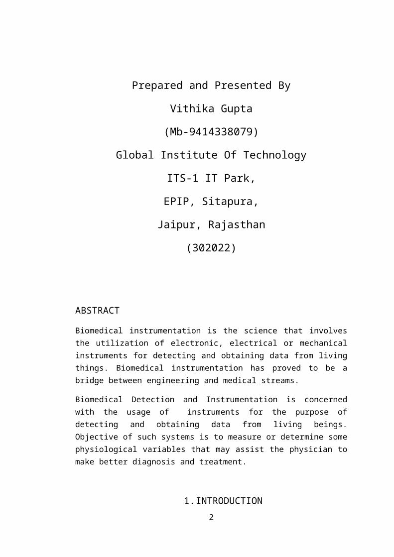
1.1 BLOCK DIAGRAM OF BIOMEDICAL DETECTION AND INSTRUMENTATION SYSTEM
Every instrumentation system has at least some of the functional components in it. A block diagram of basic biomedical detection and instrumentation system is shown.
In biomedical detection and instrumentation system the source of signals is living tissues or energy is applied to living tissues. The majority of instruments, which are used in the hospitals are electronic or electrical or mechanical systems. In general, any medical instrument could comprise of following basic parts.
(1) Measurands : The physiological signals that the system measures is called measurand. Here source of measurand is the human body. The signal may be present on the surface of body or it may be internal like blood pressure, blood flow etc.
(2) Transducers : Transducer is a device that converts one form of energy to another. It’s primary function is to provide a usable output in response to the measurand. It can measure temperature, pressure, flow or any other variables.
(3) Signal Conditioner : Signal conditioning devices include amplifiers, filters, analog to digital and digital to analog converters. It may also average repetitive signalsto reduce noise or it may convert information from the time domain to the frequency domain. Normally transducer’s output can’t be coupled directly to the display and recording devices. So it’s output is modified into suitable form for next stages by signal conditioning devices.
(4) Display and Recording Instruments : The output of whole measurement system is displayed for human operator. The display may be numerical or
3
graphical, discrete or continuous, permanent or temporary depending upon the type of measurand and how the operator will use the information. Alarm systems can also be used. Sometimes data storage devices are also used for future references.
1.2 PROBLEMS IN SENSING PHYSIOLOGICAL SIGNALS
(1) Difficult to access variables : Problem occur in accessing physiological variables because transducers cannot be placed at interior locations in the body.
(2) Sensitivity : The human body is very sensitive to external environment which results in variability of data.
(3) High degree of sensitivity among sub-systems : There are large number of physiological systems having interaction with each other resulting in stimulation of one subsystem affecting all other sub-systems.
(4) Undefined interrelationship : Result for undefined inter-relationship is that how one part of a given system affects all parts of other systems is difficult to define so measurements of large tolerance are often accepted by the physician.
(5) Loading effect : Loading effect should be avoided to get accurate results.
(6) Noise interference : Noise signals are generated and make interference with the signals under measurement.
(7) Energy limitations : In dealing with living subjects, energy level should be within safe limits.
(8) Safety considerations : Equipments must be designed to protect the patient from electrical accidents.
2. SOME BIOMEDICAL EQUIPMENTS
4
2.1 ELECTROCARDIOGRAM
Electrocardiogram is a biomedical equipment which is used for recording the electrical activity of the heart over time via skin electrodes and the process is called electrocardiography. The graph obtained after recording is called as an electrocardiograph. A typical electrocardiograph runs at a paper speed of 25 mm/s, although faster paper speeds are occasionally used. Each small block of ECG paper is 1 mm².
2.1.1 ECG Machines
Nowadays multichannel portable and roll-around models are in use. The electronic section of machine is an ECG preamplifier and a power amplifier to drive the pen assembly or the galvanometer.
Galvanometer is a permanent magnet moving coil assembly that is similar in operation to the D’Arsonval meter movement. A small bobbin wound with many turns of wire is mounted on a jewel bearing in the field of a permanent magnet. The writing point is mounted like a meter pointer, to the moving coil. The PMMC assembly is constructed so that the pen will be at rest at the center of its travel when a current flows in the coil. The direction of the pen deflection is determined by the polarity of current in the coil, while the amount of deflection is determined by the amplitude of the current. The deflection is caused by the tiny magnetic field generated by the coil current interacting with the field of the permanent magnet. The writing tip is not a pen but a stylus heated by a resistance wire. Paper used is especially treated so that it turns black when heated.
2.1.2 ECG Waveform
A typical ECG waveform and this particular waveform is typical of a measurement from right arm to left arm.
When a depolarization wavefront (or mean electrical vector) moves toward a positive electrode, it creates a positive deflection on the ECG in the corresponding lead.
When a depolarization wavefront (or mean electrical vector) moves away from a positive electrode, it creates a negative deflection on the ECG in the corresponding lead.
5
When a depolarization wavefront (or mean electrical vector) moves perpendicular to a positive electrode, it creates an equiphasic (or isodiphasic) complex on the ECG. It will be positive as the depolarization wavefront (or mean electrical vector) approaches (A), and then become negative as it passes by (B).
2.1.3 ECG Readout Devices
Two forms of ECG readout devices are commonly employed: oscilloscope stripchart recorders.
Oscilloscopes are much like other CROs, except that the vertical amplifier bandwidth is severely limited, and the CRT persistence is very long. Most oscilloscopes use horizontal speed of 25 mm/s, while some use 50 mm/s and 100 mm/s.
Medical strip-chart recorders offers same speed 25 mm/s. They may also offer 1 mm/s or 5 mm/s.
2.1.4 ECG Faults
Internal electrical or mechanical faults occur only occasionally in ECG machines, yet incidents of malfunction occur often. Following are some of the faults :
(1)Machine runs but the thermal-tip-stylus does not write or writes very lightly. This might be caused due to too little heat on the stylus and insufficient stylus pressure on the paper.
(2)Smeared traces. Cause for smeared traces might be worn stylus or incorrectly loaded paper.
(3)Poor recording. Possible cause for this might be electronic or mechanical problems, bad lead switch or input connector, bad patient cables, or improper connection to patient.
2.1.5 ECG Utilization
Electrical impulses in the heart originate in the sinoatrial node and travel through conducting system to the heart muscle.The impulses stimulate the muscle fibres to contract and thus producing the systole. The electrical waves can be measured at selectively placed electrodes (electrical contacts) on the skin. Electrodes on different `sides of the heart measure the activity of different parts of the heart muscle. An ECG displays the voltage between pairs of these electrodes, and the muscle activity that they measure, from different directions, also understood as vectors. This display indicates the overall rhythm of the heart and weaknesses in different parts of the
6
heart muscle. It is the best way to measure and diagnose abnormal rhythms of the heart particularly abnormal rhythms caused by damage to the conductive tissue that carries electrical signals, or abnormal rhythms caused by levels of dissolved salts (electrolytes), such as potassium, that are too high or low.
2.2 ELECTROENCEPHALOGRAM
The brain generates rythmical potentials which originates in the individual neurons of the brain. These potentials get summated as millions of the cell discharge synchronously and appear as a surface waveform, the recording of which is known as Electroencephalogram. (EEG) is the recording of electrical activity along the scalp produced by the firing of neurons within the brain. In clinical contexts, EEG refers to the recording of the brain's spontaneous electrical activity over a short period of time, usually 20–40 minutes, as recorded from multiple electrodes placed on the scalp.
2.2.1 EEG Machine
The basic components of electroencephalograph are explained as follows:
(1) Montages : The pattern of electrode placement on the scalp and the channels they are connected to is called a montage.
(2) Electrode Montage Selector : The EEG signals are picked up from the scalp and then transmitted to the Montage Selector. The montage Selector is a panel containing a large number of switches that allows the user to select which electrode pair will have signals subtracted from each other to create an array of channels of output called a Montage.
(3) Amplifier : Every channel has separate amplifier which is ac coupled, very sensitive and having adjustable gain with differential input since the EEG signals are small in amplitude so the amplifier used must have very high CMMR to minimize stray interference signals from mains and other electrical equipments.
(4) Filters : When recording EEG desired signal may contain muscle artefacts which must be removed by using low pass filters.
(5) Recorder : The recorder consist of a paper drive mechanism and some writing mechanism.
(6) Computers : Microprocessors are used which have a programmable montage selection.
7
2.2.2 EEG Waveform
Following are the types of EEG waveforms:
(1) Alpha(α) : Rythmic waves at frequency 9-13 Hz.
(2) Beta(β) : Occur at frequency 14-30 Hz.
(3) Theta(θ) : Occur at frequency 4-8 Hz.
(4) Delta(δ) : Occur at frequency 1-3 Hz.
2.2.3 EEG Measurement
Clinical EEG measurements are obtained from electrodes placed on the surface of the scalp. For clinical measurements surface needle electrodes are used. A suitable electrolyte paste or jelly is used in conjuction with the electrodes to enhance coupling of the ionic potentials to the input of the measuring device. Most often 10-20 electrodes system is used.
2.2.4 EEG Utilization
Routine EEG is typically used in the following clinical circumstances:
to distinguish epileptic seizures from other types of spells, such as psychogenic non-epileptic seizures, syncope, sub-cortical movement and migraine variants.
to differentiate "organic" encephalopathy or delirium from primary psychiatric syndromes such as catatonia.
to serve as an adjunct test of brain death to prognosticate, in certain instances, in patients with coma
2.3 ELECTROMYOGRAM
The bioelectric potentials associated with muscle activity are called electromyogram. These potentials can be measured at the surface of the body near a muscle of intrest or directly from the muscle by penetrating the skin with needle electrodes.
8
2.3.1 EMG Instrument
EMG is an instrument which is used for recording the electrical activity of the muscle to determine whether the muscle is contracting or not. Signals are picked up by using surface electrodes or needle electrodes inserted directly into the muscle. These electrodes pick up the potential produced by the contracting muscle fiber. This signal is then amplified by EMG amplifiers and can be displayed on CRO.
2.3.2 EMG Waveforms
EMG waveform appears very much like a random noise waveform and the energy of signal is a function of the amount of muscle activity and electrode placement. Amplitude of the waveform is the instantaneous sum of all action potentials generated at a given time.
2.3.3 Applications of EMG
(1) As a diagnostics tool for identifying neuromuscular disease, assessing low back pain, kinesiology and disorders of motor control.
(2) As a control signal for prosthetic devices such as prosthetic hands, arms, and lower limbs.
(3) As a control signal for prosthetic devices such as prosthetic hands, arms, and lower limbs.
(4) Unvoiced speech recognition recognizes speech by observing the EMG activity of muscles associated with speech. It is targeted for use in noisy environments, and may be helpful for people without vocal cords and people with aphasia.
(5) As a control signal for computers and other devices. An interface device based on EMG could be used to control moving objects, such as mobile robots or an electric wheelchair. This may be helpful for individuals who cannot operate a joystick-controlled wheelchair.
2.4 ELECTRORETINOGRAM
A record of the complex pattern of bioelectric potentials obtained from the retina of eye is called ERG. This potential changes when the eye is illuminated. The process
9
of recording the change in potential when light falls on the eye is called electroretinography.
2.4.1 ERG Machine
Electrodes are usually placed on the cornea and the skin near the eye, although it is possible to record the ERG from skin electrodes. During a recording, the patient's eyes are exposed to standardized stimuli and the resulting signal is displayed showing the time course of the signal's amplitude (voltage). Signals are very small, and typically are measured in microvolts or nanovolts. The ERG is composed of electrical potentials contributed by different cell types within the retina, and the stimulus conditions (flash or pattern stimulus, whether a background light is present, and the colors of the stimulus and background) can elicit stronger response from certain components.
2.4.2 ERG Waveform
To sufficiently bright flashes, the ERG will contain an a-wave (initial negative deflection) followed by a b-wave (positive deflection). The leading edge of the a-wave is produced by the photoreceptors, while the remainder of the wave is produced by a mixture of cells including photoreceptors, bipolar, amacrine and Muller cells
2.4.3 Applications of ERG
(1) It is used mainly by opthalmologists for the diagnosis of various retinal diseases.
(2) It is used extensively in eye research, as it provides information about the function of the retina that is not otherwise available.
2.5 ELECTROOCCULOGRAM
Electrooculography (EOG) is a technique for measuring the resting potential of the retina. The resulting signal is called the electrooculogram. Unlike the electroretinogram, the EOG does not represent the response to individual visual stimuli.
10
2.5.1 EOG Machine
Usually, pairs of electrodes are placed either above and below the eye or to the left and right of the eye. If the eye is moved from the center position towards one electrode, this electrode "sees" the positive side of the retina and the opposite electrode "sees" the negative side of the retina. Consequently, a potential difference occurs between the electrodes. Assuming that the resting potential is constant, the recorded potential is a measure for the eye position.
2.5.2 Advantages of EOG
(1) Recording with minimal interference with subject activities and minimal discomfort.
(2) Recordings can be made in total darkness and/or with the eyes closed.
2.5.3 Disadvantages of EOG
(1) The corneoretinal potential is not fixed but has found to be vary, and to be affected by light, fatigue and other qualities.
(2) Need for frequent calibration and recalibration.
2.6 MAGNETIC RESONANCE IMAGING
MRI is an advanced formof imaging that is now used widely for the diagnosis of various disease conditions. It is producing dramatic changes in the field of medical diagnostics and has been made possible by growing concern over health hazard from ionizing radiations.
2.6.1 Principle of MRI
The basic principle of MRI is based on a well known fact that 70% of human body is made up of water, made up of two integral components – Hydrogen and Oxygen. The MRI diagnostic procedure makes use of these hydrogen atoms in the body. When the human body is placed between two large magnets, these tiny magnets now change their orientation with respect to the magnetic field. This change in position of hydrogen atoms in the body picked up by sensitive devices and converted into digital images with the help of a computer.
11
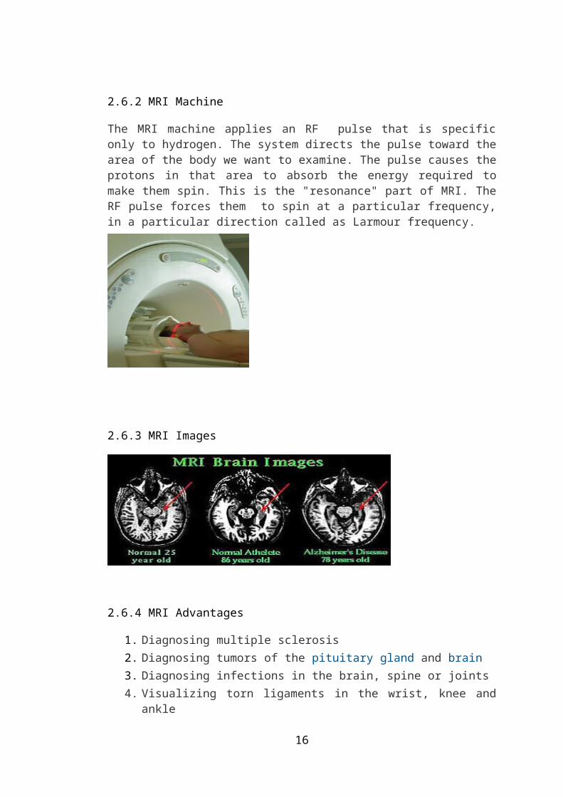
2.6.2 MRI Machine
The MRI machine applies an RF pulse that is specific only to hydrogen. The system directs the pulse toward the area of the body we want to examine. The pulse causes the protons in that area to absorb the energy required to make them spin. This is the "resonance" part of MRI. The RF pulse forces them to spin at a particular frequency, in a particular direction called as Larmour frequency.
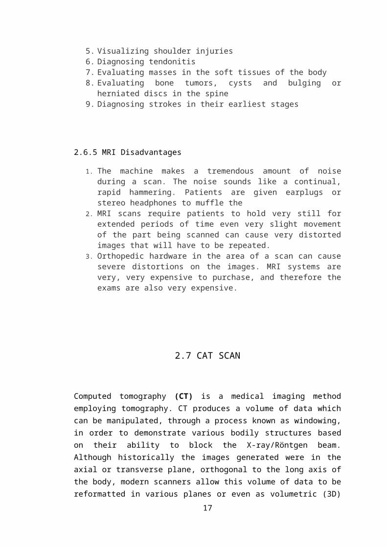
2.6.3 MRI Images
2.6.4 MRI Advantages
1. Diagnosing multiple sclerosis 2. Diagnosing tumors of the pituitary gland and brain 3. Diagnosing infections in the brain, spine or joints 4. Visualizing torn ligaments in the wrist, knee and ankle 5. Visualizing shoulder injuries 6. Diagnosing tendonitis 7. Evaluating masses in the soft tissues of the body 8. Evaluating bone tumors, cysts and bulging or herniated discs in the spine 9. Diagnosing strokes in their earliest stages
12
2.6.5 MRI Disadvantages
1. The machine makes a tremendous amount of noise during a scan. The noise sounds like a continual, rapid hammering. Patients are given earplugs or stereo headphones to muffle the
2. MRI scans require patients to hold very still for extended periods of time even very slight movement of the part being scanned can cause very distorted images that will have to be repeated.
3. Orthopedic hardware in the area of a scan can cause severe distortions on the images. MRI systems are very, very expensive to purchase, and therefore the exams are also very expensive.
2.7 CAT SCAN
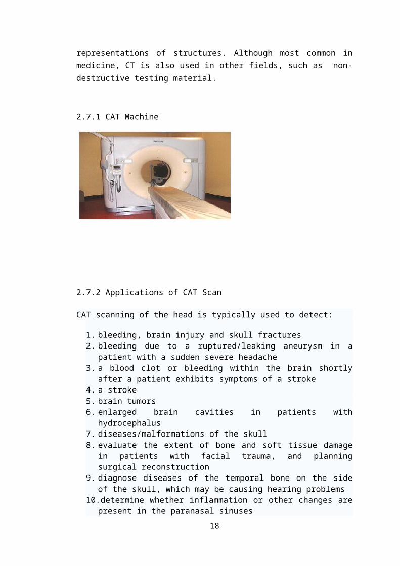
Computed tomography (CT) is a medical imaging method employing tomography. CT produces a volume of data which can be manipulated, through a process known as windowing, in order to demonstrate various bodily structures based on their ability to block the X-ray/Röntgen beam. Although historically the images generated were in the axial or transverse plane, orthogonal to the long axis of the body, modern scanners allow this volume of data to be reformatted in various planes or even as volumetric (3D) representations of structures. Although most common in medicine, CT is also used in other fields, such as non-destructive testing material.
2.7.1 CAT Machine
13
2.7.2 Applications of CAT Scan
CAT scanning of the head is typically used to detect:
1. bleeding, brain injury and skull fractures 2. bleeding due to a ruptured/leaking aneurysm in a patient with a sudden severe
headache 3. a blood clot or bleeding within the brain shortly after a patient exhibits
symptoms of a stroke 4. a stroke 5. brain tumors 6. enlarged brain cavities in patients with hydrocephalus 7. diseases/malformations of the skull 8. evaluate the extent of bone and soft tissue damage in patients with facial
trauma, and planning surgical reconstruction 9. diagnose diseases of the temporal bone on the side of the skull, which may be
causing hearing problems 10. determine whether inflammation or other changes are present in the paranasal
sinuses 11. plan radiation therapy for cancer of the brain or other tissues 12. guide the passage of a needle used to obtain a tissue sample (biopsy) from the
brain
2.7.3 Advantages of CAT Scan
1. CT completely eliminates the superimposition of images of structures outside the area of interest.
2. Because of the inherent high-contrast resolution of CT, differences between tissues that differ in physical density by less than 1% can be distinguished.
3. Data from a single CT imaging procedure consisting of either multiple contiguous or one helical scan can be viewed as images in the axial, coronal, or sagittal planes, depending on the diagnostic task. This is referred to as multiplanar reformatted imaging.
4. The improved resolution of CT has permitted the development of new investigations, which may have advantages; compared to conventional angiography
5. CT colonography may be as useful for detection of tumors, but may use a lower radiation dose.
14
2.8 ULTRASONOGRAPHY
Ultrasonography is an ultrasound-based diagnostic imaging technique used to visualize subcutaneous body structures including tendons, muscles, joints, vessels and internal organs for possible pathology or lesions.
2.8.1 Ultrasonography instrument
A sound wave is typically produced by a piezoelectric transducer encased in a probe. Strong, short electrical pulses from the ultrasound machine make the transducer ring at the desired frequency. The frequencies can be anywhere between 2 and 18 MHz. The sound is focused either by the shape of the transducer, a lens in front of the transducer, or a complex set of control pulses from the ultrasound scanner machine. This focusing produces an arc-shaped sound wave from the face of the transducer. The wave travels into the body and comes into focus at a desired depth.
15
2.8.2 Modes of sonography
Four different modes of ultrasound are used in medical imaging[6]. These are:
A-mode: A single transducer scans a line through the body with the echoes plotted on screen as a function of depth.
B-mode: In B-mode ultrasound, a linear array of transducers simultaneously scans a plane through the body that can be viewed as a two-dimensional image on screen.
M-mode: M stands for motion. In m-mode a rapid sequence of B-mode scans whose images follow each other in sequence on screen enables doctors to see and measure range of motion, as the organ boundaries that produce reflections move relative to the probe.
Doppler mode: This mode makes use of the Doppler effect in measuring and visualizing blood flow
2.8.3 Diagnostic Applications
Ultrasonography is widely used in medicine. Sonography is effective for imaging soft tissues of the body. Superficial structures such as muscles, tendons, testes, breast and neonatal brain imaged at a higher frequency (7-18 MHz), which provides better axial and lateral resolution. Deeper structures such as liver and kidney are imaged at a lower frequency 1-6 MHz with lower axial and lateral resolution but greater penetration.
2.8.4 Therapeutic Applications
Therapeutic applications use ultrasound to bring heat or agitation into the body. Therefore much higher energies are used than in diagnostic ultrasound. In many cases the range of frequencies used are also very different.
1. Ultrasound may be used to clean teeth indental hygiene. 2. Ultrasound sources may be used to generate regional heating and mechanical
changes in biological tissue, 3. Focused ultrasound may be used to generate highly localized heating to treat
cysts and tumors (benign or malignant), This is known as Focused Ultrasound Surgery (FUS) or High Intensity Focused Ultrasound Focused ultrasound Ultrasound may be used for catract treatment by phacoemulsification.
4. Procoagulant at 5-12MHz
16
References :
Books
John G. Webster, 1998 Medical Instrumentation Application And Design, third ed, Wiley
Joseph J. Carr, John M Brown, 2001 Introduction To Biomedical Equipment And Technology, fourth ed.
Jitendra K. Jain, Neeraj Jain, Biomedical Instrumentation.
Interscience, New York, pp. 54–59.
Chapters in edited books
Marcus, B.C., Nemo, A., 1992.
Winchester, F., Yu, S., Pfaff, S.W., Major, K. (Eds.), York, pp. 1393–1399.
17
18


![Biomedical Instrumentation/ - VoWi · Biomedical Instrumentation/ Biomedizinische Technik 2015, [354.042] Professors: Kaniusas, Wanzenböck, Bertagnolli, Mayr,... Basic Principles](https://static.fdocuments.net/doc/165x107/5e7697081f9ffe701a741e6f/biomedical-instrumentation-vowi-biomedical-instrumentation-biomedizinische-technik.jpg)