Paper International Journal of Informative & Futuristic ... · International Journal of Informative...
8
2539 www.ijifr.com Copyright © IJIFR 2015 Research Paper International Journal of Informative & Futuristic Research ISSN (Online): 2347-1697 Volume 2 Issue 8 April 2015 Abstract Simulation of compressors in an Ammonia synthesis unit (Production of ammonia) process is gaining importance and so the process needs to be studied .With the advent of computers and simulating software’s like “ASPEN PLUS” it is possible to design and optimize a particular process. A Multi-stage Compressor is taken into consideration and hence-forth simulation is done controlling the pressure, increasing at stages and reducing the volume. Proper design can significantly reduce production cost as well as provide to make the process safe and reduce environment hazards. Steady state simulation is done. Each unit is taken into consideration and the variables are been optimized. The units are sequentially optimized. 1. Introduction In industry complicated problems are often not solved by hand for two reasons: human error and time constraints. There are many different simulation programs used in industry depending on the field, application, and desired simulation products (entire process unit, one piece of equipment, etc.). When used to its full capabilities, Aspen can be a very powerful tool for a Chemical Engineer in a variety of fields including oil and gas production, refining, chemical processing, environmental studies, and power generation to name a few. Process simulation allows you to predict the behaviour of a process by using basic engineering relationships, such as mass and energy balances, and phase and chemical equilibrium. Given reliable Simulation of Compressors by Aspen Plus Paper ID IJIFR/ V2/ E8/ 013 Page No. 2539-2546 Subject Area Chemical Engineering Key Words Simulation, Design, Compressors, Steady State, Dynamic Nimesh Kamat 1 B.E. Student, Department of Chemical Engineering, Bharati Vidyapeeth College Of Engineering, Navi Mumbai-Maharashtra, India Dr. S.M. Walke 2 Professor, Department of Chemical Engineering, Bharati Vidyapeeth College Of Engineering, Navi Mumbai-Maharashtra, India
Transcript of Paper International Journal of Informative & Futuristic ... · International Journal of Informative...

2539
www.ijifr.com Copyright © IJIFR 2015
Research Paper Paper
International Journal of Informative & Futuristic Research ISSN (Online): 2347-1697
Volume 2 Issue 8 April 2015
Abstract
Simulation of compressors in an Ammonia synthesis unit (Production of
ammonia) process is gaining importance and so the process needs to be studied
.With the advent of computers and simulating software’s like “ASPEN PLUS” it is
possible to design and optimize a particular process. A Multi-stage Compressor is
taken into consideration and hence-forth simulation is done controlling the
pressure, increasing at stages and reducing the volume. Proper design can
significantly reduce production cost as well as provide to make the process safe
and reduce environment hazards. Steady state simulation is done. Each unit is
taken into consideration and the variables are been optimized. The units are
sequentially optimized.
1. Introduction
In industry complicated problems are often not solved by hand for two reasons: human error and
time constraints. There are many different simulation programs used in industry depending on the
field, application, and desired simulation products (entire process unit, one piece of equipment, etc.).
When used to its full capabilities, Aspen can be a very powerful tool for a Chemical Engineer in a
variety of fields including oil and gas production, refining, chemical processing, environmental
studies, and power generation to name a few.
Process simulation allows you to predict the behaviour of a process by using basic engineering
relationships, such as mass and energy balances, and phase and chemical equilibrium. Given reliable
Simulation of Compressors by Aspen Plus Paper ID IJIFR/ V2/ E8/ 013 Page No. 2539-2546 Subject Area
Chemical
Engineering
Key Words Simulation, Design, Compressors, Steady State, Dynamic
Nimesh Kamat 1
B.E. Student, Department of Chemical Engineering, Bharati Vidyapeeth College Of Engineering, Navi Mumbai-Maharashtra, India
Dr. S.M. Walke 2
Professor, Department of Chemical Engineering, Bharati Vidyapeeth College Of Engineering, Navi Mumbai-Maharashtra, India

2540
ISSN (Online): 2347-1697 International Journal of Informative & Futuristic Research (IJIFR)
Volume - 2, Issue - 8, March 2015 20th Edition, Page No: 2539-2546
Nimesh Kamat , Dr. S.M. Walke :: Simulation of Compressors by Aspen Plus
thermodynamic data, realistic operating conditions, and rigorous equipment models, you can
simulate actual plant behaviour. Process simulation enables you to run many cases, conduct "what
if" analyses, and perform sensitivity studies and optimization runs. With simulation, you can design
better plants and increase profitability in existing plants.
a) Simulation Modes:
There are two modes of simulation-
1) Steady state mode
2) Dynamic mode.
b) Steady State Mode and Dynamic Mode :-
A simulation program may be used for steady state or dynamic simulation. In the first case, a
material and energy balance for steady state operation of the chemical plant must be done. In the
second case, the time varying operation of the plant is simulated. Dynamic simulation is the more
complicated and computationally expensive of the two. Initially process simulation was used to
simulate steady state processes.
Dynamic simulation is an extension of steady-state process simulation whereby time-dependence is
built into the models via derivative terms i.e. accumulation of mass and energy.
Dynamic simulations require increased calculation time and are mathematically more complex than
a steady state simulation. It can be seen as a multiply repeated steady state simulation (based on a
fixed time step) with constantly changing parameters.
Dynamic simulation can be used in both online and offline fashion. The online case being model
predictive control, where the real-time simulation results are used to predict the changes that would
occur for a control input change and the control parameters are optimized based on the results.
c) Various Process Simulators:-
Aspen Plus.
Aspen Hysys.
Aspen Custom Modeller by Aspen Technology.
CHEMASIM.
CHEMCAD.
2. Aspen PLUS Process Simulator
Aspen PLUS process simulator is a core element of engineering applications. It provides quite
accurate results which makes it an efficient simulator. It provides comprehensive thermodynamics
basis for accurate determination of physical properties, transport properties, and phase behaviour.
Aspen PLUS can be used to determine outlet process conditions if the inlet conditions like
temperature, pressure, and composition are specified. Aspen PLUS has established itself as a very
intuitive and easy to use process simulator in oil and gas refining industry. Users with little prior
knowledge of Aspen PLUS can pick up and train themselves in its modelling capabilities. Some of
the very intuitive capabilities include a highly interactive process flow diagram for building and
2541
ISSN (Online): 2347-1697 International Journal of Informative & Futuristic Research (IJIFR)
Volume - 2, Issue - 8, March 2015 20th Edition, Page No: 2539-2546
Nimesh Kamat , Dr. S.M. Walke :: Simulation of Compressors by Aspen Plus
navigating through large simulations. The program also provides a very flexible and easy to use
distillation column modelling environment. Additionally the interactive nature of PLUS enables
users to build and use their models quickly and effectively.
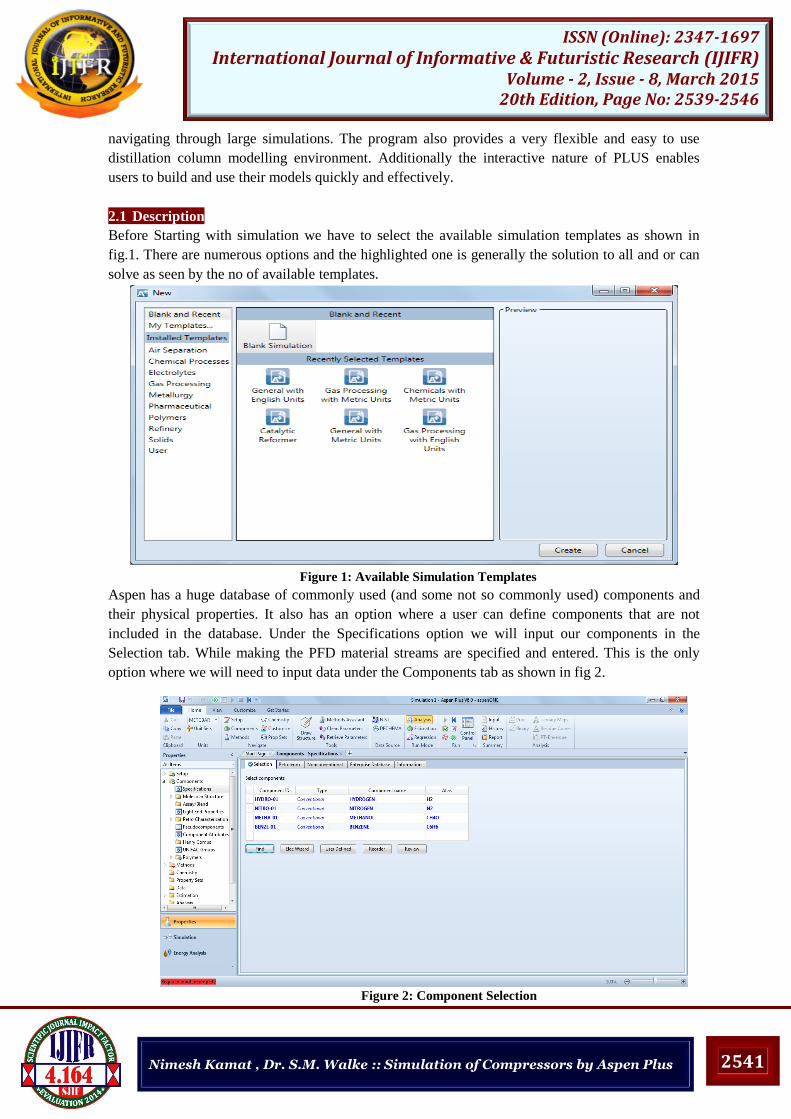
2.1 Description
Before Starting with simulation we have to select the available simulation templates as shown in
fig.1. There are numerous options and the highlighted one is generally the solution to all and or can
solve as seen by the no of available templates.
Figure 1: Available Simulation Templates
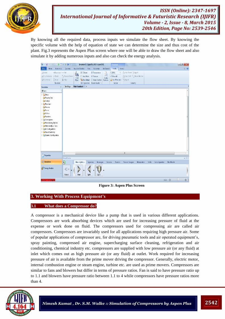
Aspen has a huge database of commonly used (and some not so commonly used) components and
their physical properties. It also has an option where a user can define components that are not
included in the database. Under the Specifications option we will input our components in the
Selection tab. While making the PFD material streams are specified and entered. This is the only
option where we will need to input data under the Components tab as shown in fig 2.
Figure 2: Component Selection
2542
ISSN (Online): 2347-1697 International Journal of Informative & Futuristic Research (IJIFR)
Volume - 2, Issue - 8, March 2015 20th Edition, Page No: 2539-2546
Nimesh Kamat , Dr. S.M. Walke :: Simulation of Compressors by Aspen Plus
By knowing all the required data, process inputs we simulate the flow sheet. By knowing the
specific volume with the help of equation of state we can determine the size and thus cost of the
plant. Fig.3 represents the Aspen Plus screen where one will be able to draw the flow sheet and also
simulate it by adding numerous inputs and also can check the energy analysis.
Figure 3: Aspen Plus Screen
3. Working With Process Equipment’s
3.1 What does a Compressor do?
A compressor is a mechanical device like a pump that is used in various different applications.
Compressors are work absorbing devices which are used for increasing pressure of fluid at the
expense or work done on fluid. The compressors used for compressing air are called air
compressors. Compressors are invariably used for all applications requiring high pressure air. Some
of popular applications of compressor are, for driving pneumatic tools and air operated equipment’s,
spray painting, compressed air engine, supercharging surface cleaning, refrigeration and air
conditioning, chemical industry etc. compressors are supplied with low pressure air (or any fluid) at
inlet which comes out as high pressure air (or any fluid) at outlet. Work required for increasing
pressure of air is available from the prime mover driving the compressor. Generally, electric motor,
internal combustion engine or steam engine, turbine etc. are used as prime movers. Compressors are
similar to fans and blowers but differ in terms of pressure ratios. Fan is said to have pressure ratio up
to 1.1 and blowers have pressure ratio between 1.1 to 4 while compressors have pressure ratios more
than 4.

2543
ISSN (Online): 2347-1697 International Journal of Informative & Futuristic Research (IJIFR)
Volume - 2, Issue - 8, March 2015 20th Edition, Page No: 2539-2546
Nimesh Kamat , Dr. S.M. Walke :: Simulation of Compressors by Aspen Plus
3.2 Types of Compressors
Figure 4: Types of Compressors
Compressors are generally divided into two categories:
• Positive Displacement Compressors
• Dynamic Compressors
Positive displacement compressors in essence work by entrapping a volume of gas and
subsequently reducing this volume which in turn increases the pressure.
Dynamic compressors generally work by imparting movement to the gas; i.e. kinetic energy
is transferred from the machines internals to the gas. By subsequent reduction of this
velocity the kinetic energy is converted into potential energy – pressure.
The image above shows the available types of compressors. The most common ones used in
refrigeration are described below:
3.3 Working with Compressor
The compressor operation is used to increase the pressure on inlet gas stream. Depending on the
information specified, the compressor calculates either a unknown temperature, pressure or
compressor efficiency.
The Compressor block can be used to simulate:
Polytrophic Centrifugal compressor
Polytrophic positive displacement compressor
Isentropic compressor
Isentropic turbine
M Compressor is used for multi-stage compressors. Power requirement is calculated or input. A
Heater model can be used for pressure change calculations only. Compressor is designed to handle
both single and multiple phase calculations. Rating can be done by specifying a compressor
performance curve.
Specify:
Dimensional curves
Head versus flow.

2544
ISSN (Online): 2347-1697 International Journal of Informative & Futuristic Research (IJIFR)
Volume - 2, Issue - 8, March 2015 20th Edition, Page No: 2539-2546
Nimesh Kamat , Dr. S.M. Walke :: Simulation of Compressors by Aspen Plus
Power versus flow.
Head coefficient versus flow coefficient.
3.4 Compressors in Aspen Plus
A compressor in Aspen Plus takes similar inputs and output material and work streams as
that of a pump.
Figure 5:- Compressor in Aspen Plus
Unlike pumps, here you need to specify the compressor operating conditions, based on
experience or manufacturer recommendations and information.
The outlet conditions can be either input directly as pressure specification, determined from
input power, or determined from performance curves.
If the last option is used, the performance curve must be given in Performance Curves sheet
in a similar manner to that for the pump.
The pump efficiency can be input directly as a scalar quantity, or it can be calculated from
efficiency curves. In both cases, the efficiency will have a direct effect on BHP calculations for
the compressor.
Figure 6:- Compressor Specifications Sheet

2545
ISSN (Online): 2347-1697 International Journal of Informative & Futuristic Research (IJIFR)
Volume - 2, Issue - 8, March 2015 20th Edition, Page No: 2539-2546
Nimesh Kamat , Dr. S.M. Walke :: Simulation of Compressors by Aspen Plus
4. Simulation of Compressor in Aspen plus
The figure below represents the schematic diagram of compressor in aspen plus. The feed comes
into the compressor 1 and then it is cooled in a cooler 1 and then again for increasing the pressure it
goes in compressor 2 and cooled in cooler 2.
Figure 7: Simulation of Compressor
The feed conditions are as follows:-
Table 1:- Feed Input
FEED
Temperature F 75
Pressure psia 14.7
Vapor Frac 1
Mole Flow lbmol/hr 128.51
Mass Flow lb/hr 3600
Volume Flow cuft/hr 50157.4
Enthalpy MMBtu/hr -0.002
Mole Flow lbmol/hr
NITRO-01 128.51
Table 2:- Simulation Result

2546
ISSN (Online): 2347-1697 International Journal of Informative & Futuristic Research (IJIFR)
Volume - 2, Issue - 8, March 2015 20th Edition, Page No: 2539-2546
Nimesh Kamat , Dr. S.M. Walke :: Simulation of Compressors by Aspen Plus
5. Conclusion
The goal of Plus is to provide a capability to design an entire process completely and accurately.
Steady-state simulation is a powerful process engineering tool that enables engineers to simulate
plant behaviour and analyse their results rapidly. The process simulation capabilities of Aspen Plus
enables engineers to predict the behaviour of a process using basic engineering relationships such as
mass and energy balances, phase and chemical equilibrium, and reaction kinetics. With reliable
thermodynamic data, realistic operating conditions and the rigorous Aspen Plus equipment models,
they can simulate actual plant behaviour. Aspen Plus provides an extremely powerful approach to
steady state modelling. Aspen brings the power of steady-state process simulation to the engineering
desktop, and delivers both modelling power and ease of use. With Aspen Plus, companies can
design, simulate, troubleshoot and manage profitable process plants. It solves the critical engineering
and operating problems that arise throughout the lifecycle of a chemical process, such as designing a
new process, troubleshooting a process unit or optimizing operations of a full process like an
Ammonia synthesis plant.
Acknowledgements
This work was done by Nimesh Kamat as a part of their BE project work during June 2014 to Feb
2015,at the Department of Chemical Engineering, Bharati Vidyapeeth College of Engineering, Navi
Mumbai, India, under the guidance of Dr. S.M. Walke. We are thankful to the authorities at Bharati
Vidyapeeth College of Engineering, Navi Mumbai for providing all facilities for completing this
work.
References
[1] Mohd.Kamaruddin Abd Hamid “Plus: An introduction to Chemical Engineering Simulation”.
[2] Michael E Hanyak “Chemical Process Simulation and Aspen tech Plus Software” Version 2006 Bucknell
university Lewisburg PA 17837 December 15 2007.
[3] Aspen Plus@ 2004.2 Dynamic Modeling.[5] Issues addresses by Process Modeling (Aspen Plus) V7.2
Cumulative patch 2, September 2010.
[4] Teemu, T.S., Pekka, R., Juha, H., Jari, B., “Predicting off-design range and performance of two-stage
centrifugal compressor ”, International Journal of Refrigeration, 33 (6), 1152-1160 (2010).
5] MIT, Aspen-tech, User’s Guide of ASPEN PLUS 10, USA (2001).
[6] Luyben W. L., Distillation Design and Control Using Aspen Simulation, Wiley, New
York (2006).