PanelMateâ Hardware Installation Guideautomation-interface.com/pdfs/IM04802003E.pdf · Eaton...
66
Eaton Corporation Cutler-Hammer Business Unit 811 Green Crest Drive Columbus, OH 43081 PanelMate Hardware Installation Guide
Transcript of PanelMateâ Hardware Installation Guideautomation-interface.com/pdfs/IM04802003E.pdf · Eaton...

Eaton Corporation Cutler-Hammer Business Unit 811 Green Crest Drive Columbus, OH 43081
PanelMate Hardware Installation Guide

Preface Information in this manual is subject to change without notice and does not represent a commitment on the part of Eaton’s Cutler-Hammer, Inc. Permission is granted to duplicate this material without modification only for your use or the internal use of other members of your company or your agents to assist you in the use and servicing of products purchased from Eaton’s Cutler-Hammer. No permission is granted to modify this material or include this material in a compilation.
RESTRICTED RIGHTS LEGEND
Use, duplication, or disclosure by the Government is subject to restrictions set forth in paragraph (b)(3)(B) of the Rights in Technical Data and Computer Software clause of DAR 7-104.9(a). Contractor/Manufacturer is Eaton Corporation’s Cutler-Hammer Business Unit, 811 Green Crest Drive, Columbus, OH 43081.
TRADEMARKS
PanelMate is a federally registered trademark of Eaton Corporation. MS-DOS, Microsoft, and Windows are federally registered trademarks of Microsoft Corporation. Data Highway and Data Highway Plus are trademarks of Allen-Bradley. DeviceNet is a trademark of Open DeviceNet Vendor Association. Iomega is a federally registered trademark of Iomega Corporation.
Commercial brand names (trademarks) of products of manufacturers or developers, other than Eaton Corporation or its affiliates, that appear in this manual may be registered or unregistered trademarks of those respective manufacturers or developers, which have expressed neither approval nor disapproval of Cutler-Hammer products and services.
2002 Eaton Corporation. All rights reserved.
Printed in the United States of America.
P/N 01-00436-06

Support Services
The goal of Eaton’s Cutler-Hammer business unit is to ensure your greatest possible satisfaction with the operation of our products. We are dedicated to providing fast, friendly and accurate assistance. That is why we offer you so many ways to get the support you need. Whether it's by phone, fax or email, you can access Eaton’s Cutler-Hammer support information 24 hours a day, seven days a week. Our wide range of services are listed below. You should contact your local distributor for product pricing, availability, ordering, expediting and repairs.
Website Address www.cutler-hammer.eaton.com
Use the Cutler-Hammer website to find product information. You can also find information on local distributors or Cutler-Hammer sales offices.
e-COM Support Center VOICE: 800-356-1243 (8AM-6PM EST) FAX: 800-752-8602 AFTER-HOURS EMERGENCY: • 800-543-7038 (6PM-8AM EST)
Call the e-COM Support Center if you need assistance with placing an order, stock availability or proof of shipment, expediting an existing order, emergency shipments, product price information, returns other than warranty returns, and information on local distributors or sales offices.
e-TRC Technical Resource Center (support for OI, PLC & IPC)
VOICE: • 800-809-2772, selection 5 (8AM-5PM EST) • 414-449-7100, selection 5 (8AM-5PM EST) FAX: 614-882-0417 EMAIL: [email protected] AFTER-HOURS EMERGENCY (PLANT DOWN ONLY): • 800-809-2772, selection 5 (5PM-8AM EST) • 414-449-7100, selection 5 (5PM-8AM EST)
If you are in the US or Canada, and have OI/PLC/IPC questions, you can take advantage of our toll-free line for technical assistance with hardware and software product selection, system design and installation, and system debugging and diagnostics. Technical support engineers are available for calls during regular business hours.
European PanelMate Support Center
VOICE: +41 1 806 64 44 (9AM-5PM CET) EMAIL: [email protected]
This center, located in Zurich, Switzerland, provides high-level quality support and product repair services for your PanelMate products. You will receive real-time technical and application support.
Information Fax-Back Service For Legacy Products
VOICE: 614-899-5323
Legacy Cutler-Hammer product information, specifications, technical notes and company news are available to you via fax through this direct document request service. Using a touch-tone phone, you can select any of the info faxes from our automated product literature and technical document library, enter a fax number and receive the information immediately.
Repair and Upgrade Service (support for OI & IPC)
VOICE: • 800-809-2772, selection 5, 4 (8AM-5PM EST) • 414-449-7100, selection 5, 4 (8AM-5PM EST) FAX: 614-882-3414 EMAIL: [email protected]
If you have questions regarding the repair or upgrade of an OI/IPC, contact your local distributor. Additional support is also available from our well-equipped Repair and Upgrade Service department.

2 PanelMate Hardware Installation Guide
Table of Contents Table of Contents ................................................................................................................................2
Introduction .........................................................................................................................................4
The Three Most Critical Installation Issues.......................................................................................5 Replacing Existing PanelMate Power Series Units ...........................................................................6
Enclosure Selection..............................................................................................................................7
Enclosure Rating ...............................................................................................................................8 Enclosure Construction .....................................................................................................................8 Enclosure Sizing and Unit Positioning..............................................................................................8
Potential Problem Areas ...............................................................................................................9 Enclosure Size vs. Average Internal Temperature Rise ..............................................................10
Communication Cable Selection, Shielding, Grounding, and Termination .................................12
Overview.........................................................................................................................................13 Power and Ground Instructions.......................................................................................................14 RS-232 Communications ................................................................................................................15
RS-232 Grounding Recommendations........................................................................................15 RS-232 Shielding Recommendations..........................................................................................15
RS-422 Communications ................................................................................................................16 RS-422 Grounding Recommendations........................................................................................16 RS-422 Shielding Recommendations..........................................................................................16
RS-485 Multi-Drop Communications .............................................................................................17 RS-485 Shielding Recommendations..........................................................................................17
Allen-Bradley DH-485 Communications ........................................................................................18 Allen-Bradley Data Highway/Data Highway Plus Communications...............................................19 Allen-Bradley Remote I/O Link Communications ..........................................................................20 GE Fanuc Genius I/O Communications ..........................................................................................21 Modicon Modbus Plus Communications ........................................................................................22 DeviceNet Communications............................................................................................................23 Profibus DP Communications .........................................................................................................24
Profibus DP Shielding Recommendations ..................................................................................24 Using PanelMate on a Profibus DP network...............................................................................24
Cable Segregation and Placement....................................................................................................25
Cable Segregation ...........................................................................................................................26 Cable Placement..............................................................................................................................27
Replacing an Existing PanelMate Power Series Unit .....................................................................28
Replacing a 120VAC PanelMate Power Series unit with another 120VAC PanelMate Power Series unit. .................................................................................................................................................29 Replacing a 120VAC PanelMate Power Series unit with a 24VDC PanelMate Power Pro/Pro LT unit ..................................................................................................................................................29 Upgrading a PanelMate Power Series Model 1500 unit with a PanelMate Power Pro Model 1700 or Pro LT Model 1100 unit .............................................................................................................30

Table of Contents 3
Cutout and Unit Dimensions ............................................................................................................31
PanelMate 55XX Keypad Unit Dimensions....................................................................................32 PanelMate 57XX Keypad Unit Dimensions....................................................................................33 PanelMate 55XX/57XX Keyboard Cutout Dimensions..................................................................34 PanelMate 52XX Split Architecture Unit Dimensions....................................................................35 PanelMate 54XX Split Architecture Unit Dimensions....................................................................36 PanelMate 52XX/54XX Split Architecture Cutout Dimensions .....................................................37 PanelMate 55XX Touchscreen Unit Dimensions............................................................................38 PanelMate 57XX Touchscreen Unit Dimensions............................................................................39 PanelMate 55XX/57XX Touchscreen Cutout Dimensions .............................................................40 PanelMate 4000 Keypad Unit Dimensions .....................................................................................41 PanelMate 4000 Keypad Cutout Dimensions..................................................................................42 PanelMate 4000 Split Architecture Unit Dimensions .....................................................................43 PanelMate 4000 Split Architecture Cutout Dimensions..................................................................44 PanelMate 4000 Touchscreen Unit Dimensions .............................................................................45 PanelMate 4000 Touchscreen Cutout Dimensions..........................................................................46 PanelMate 3000 Keyboard Unit Dimensions..................................................................................47 PanelMate 3000 Keypad Cutout Dimensions..................................................................................48 PanelMate 3000 Touchscreen Unit Dimensions .............................................................................49 PanelMate 3000 Touchscreen Cutout Dimensions..........................................................................49 PanelMate 3000 Touchscreen Cutout Dimensions..........................................................................50 PanelMate 2000 Model 26xx Keyboard Unit Dimensions..............................................................51 PanelMate 2000 Model 26xx Keyboard Cutout Dimensions..........................................................52 PanelMate 2000 Model 24xx Keyboard Unit Dimensions..............................................................53 PanelMate 2000 Model 24xx Keyboard Cutout Dimensions..........................................................54 PanelMate 1100/1700 Keyboard Unit Dimensions.........................................................................55 PanelMate 1100/1700 Keyboard Cutout Dimensions .....................................................................56 PanelMate 1100/1700 Touchscreen Unit Dimensions ....................................................................57 PanelMate 1100/1700 Touchscreen Cutout Dimensions ................................................................58 PanelMate 1500 Keyboard Unit Dimensions..................................................................................59 PanelMate 1500 Keyboard Cutout Dimensions ..............................................................................60 PanelMate 1500 Touchscreen Unit Dimensions .............................................................................61 PanelMate 1500 Touchscreen Cutout Dimensions..........................................................................62
Index...................................................................................................................................................63
Reader Comment Card.....................................................................................................................64

4 PanelMate Hardware Installation Guide
Introduction
This chapter addresses:
• Critical Installation Issues
• Replacing Existing PanelMate Power Series Units

Chapter 1: Introduction 5
The Three Most Critical Installation Issues With more than 100,000 PanelMate units currently in operation since its introduction in 1986, Cutler-Hammer Technical Support has helped many users troubleshoot their PanelMate installations. This Installation Guide is intended to help you avoid the common mistakes made by first-time PanelMate users.
Three aspects of your installation are critical to long life and reliable operation:
• Enclosure selection
• Communication cable selection, shielding, grounding and termination
• Cable segregation and placement
This Installation Guide reviews each of these areas, providing recommendations and guidelines for making knowledgeable installation decisions.

6 PanelMate Hardware Installation Guide
Replacing Existing PanelMate Power Series Units If you are planning to replace an existing PanelMate Power Series unit with a new PanelMate Power Series/Power Pro/Pro LT unit, there are several very important steps to take to ensure proper operation. See Chapter 5: Replacing Existing PanelMate Units.

Chapter 2: Enclosure Selection 7
Enclosure Selection
This chapter addresses:
• Enclosure Rating
• Enclosure Construction
• Enclosure Sizing and Unit Positioning

8 PanelMate Hardware Installation Guide
Enclosure Rating The front panels of PanelMate units provide a Type 4 or Type 12 rating when mounted in a correspondingly-rated enclosure. Some PanelMate models are also rated for Type 4X installations. Make sure the enclosure you choose will meet or exceed your application’s Type rating requirement.
Enclosure Construction An enclosure constructed of cold rolled steel is recommended. This will help guard your unit against electromagnetic interference, as well as provide proper structural support and good heat dissipation.
Enclosure Sizing and Unit Positioning Careful enclosure sizing is important for proper heat dissipation and easy installation and maintenance. For efficient convection cooling, free space is needed around the PanelMate unit and the unit should be mounted in a vertical position. Convection cooling draws a vertical column of air upward over internal circuitry through the vents in the unit. In all installations, the cooling air must not exceed the maximum specified ambient temperature. This determination must be made for the maximum expected plant temperature (maximum temperature of the air surrounding the enclosure.)
• Maintain recommended free space above and below the PanelMate unit. (see table on next page)
• Avoid mounting other heat-generating equipment near the PanelMate unit. If no other location is available, mount the equipment beside or behind the PanelMate unit. If side/rear space is not available, it is preferable to mount the other equipment above rather than below the PanelMate unit. Be sure to maintain the recommended free space area between the PanelMate unit and the other equipment.
• Leave room for easy access to circuit boards, wiring/cable connections, and regular maintenance.

Chapter 2: Enclosure Selection 9
Potential Problem Areas • Enclosure is too small or PanelMate unit is not mounted in a vertical position for efficient
convection cooling
• Heat-generating devices cause internal temperature to rise above the operator interface’s ratings
• Enclosure is mounted near devices generating high levels of magnetic or electrical interference
• Free air space is not present around the outside of the enclosure – prevents the enclosure’s metal panels from dissipating internal heat
PanelMate Model
Maximum Operating Ambient Temperature
Unit Heat Output
Recommended Free Space
1100 Series 50OC 78 BTU/hr (23W)
2” minimum, 4” recommended
1500 Series 50OC Grayscale & Color TFT 40OC Color Dual-scan
41 BTU/hr (12W) 2” minimum
1700 Series 50OC 78 BTU/hr (23W) 2” minimum, 4” recommended
2000 Series Grayscale
50OC 188 BTU/hr (55 W)
6” minimum
3000 Series Grayscale & Color Dual-scan
40OC
119 BTU/hr (35W)
6” minimum
*102 BTU/hr (30W@24VDC)
3000 Series Color TFT*
50OC
*119 BTU/hr (35W@120VAC)
6” minimum
4000 Series 50OC 273 BTU/hr (80W)
6” minimum
*102 BTU/hr (30W@24VDC)
5000 Series
50OC 137 BTU/hr (40W@120VAC)
6”minimum
*Note: 3000 Series Color TFT and 5000 Series units are available in 24VDC and 120VAC versions
Note: Free space area is the space between the PanelMate unit’s electronics and the top or bottom of the enclosure.
If the inside temperature of the enclosure is above the PanelMate unit’s recommended range (see table), you must use filtered fans, heat exchangers, or air conditioners to lower the temperature. Because hot air rises to the top of an enclosure, the temperature inside can vary greatly from bottom to top. A fan can be used to circulate air within the enclosure to maintain a more uniform temperature. Make sure the magnetic properties of the equipment used to cool the enclosure do not interfere with your PanelMate unit’s operation. CRT monitors are especially susceptible to magnetic fields.
Note: If an air-purged enclosure is used, it is recommended that the inside/outside pressure differential not exceed .5 PSI.
The following sizing table is offered as an aid in the selection of enclosures to be used with PanelMate products. Cutler-Hammer offers no guarantee or warranty to the specific applicability of this table as

10 PanelMate Hardware Installation Guide
actual conditions may vary and methods of the use of our products are beyond our control. For specific information about enclosure selection and cooling methods, contact your enclosure vendor.
Note: Cutout and unit dimensional information is provided in Appendix A.
PanelMate Model Enclosure Size Avg. Internal Temp. Rise
16x16x4 11o C 16x16x6 9o C
1100 w/keypad or touchscreen
20x16x6 8o C 12x12x6 14o C 1100 w/touchscreen 12x14x6 13o C 16x16x4 7o C 16x16x6 6o C
1500 w/keypad
20x16x6 6o C 12x12x4 11o C 12x12x6 11o C
1500 w/touchscreen
12x14x6 10o C 16x16x4 11o C 16x16x6 9o C
1700 w/keypad or touchscreen
20x16x6 8o C 12x12x6 14o C 1700 w/touchscreen 12x14x6 13o C 24x20x12 10o C 24x24x12 9o C
2000 Gray Scale
30x24x12 7o C 24x20x6 7o C All 3000 (24VDC) 24x24x6 5o C 24x20x8 7o C All 3000 (120VAC) 24x24x8 7o C 30x24x16 9o C 30x24x20 8o C
All 4000
36x30x16 7o C 30x24x8 4o C 5000 w/ keypad (24VDC) 30x24x10 4o C 30x24x8 6o C 5000 w/ keypad (120VAC) 30x24x10 6o C 24x24x8 5o C 24x24x10 5o C
5000 w/touchscreen (24VDC)
24x30x8 4o C 24x24x8 7o C 24x24x10 7o C
5000 w/touchscreen (120VAC)
24x30x8 6o C
Enclosure Size vs. Average Internal Temperature Rise
The table above makes the following assumptions:
• Enclosure is fabricated from cold rolled steel

Chapter 2: Enclosure Selection 11
• All sides of the enclosure are uninsulated (free standing)
• Recommended minimum clearance between the PanelMate unit and the top and bottom of the enclosure
• No other heat-generating equipment is installed in the enclosure
Note: The temperature rise shown represents the temperature rise in the enclosure above the outside temperature. For example: if the temperature outside the enclosure in 35oC and the temperature rise in the enclosure is 10oC, then the average temperature inside the enclosure will be 45oC.

12 PanelMate Hardware Installation Guide
Communication Cable Selection, Shielding, Grounding, and Termination
This chapter addresses:
• Popular communication interface options

Chapter 3: Communication Cable Selection, Shielding, Grounding, and Termination 13
Overview A variety of communication interface options are available for PanelMate products. Options include:
• RS-232 and RS-422 based communications
• RS-485 multi-drop communications
• “Open” multi-drop networks (examples: DeviceNet, Profibus)
• Proprietary PLC networks (examples: A-B Data Highway, GEnius I/O, Modbus Plus)
Your communication interface choice should be based on the requirements of your total control system. The communications option you choose determines the precautions you need to take when installing and connecting your PanelMate unit.
For easy reference, this chapter contains a summary of seven popular communication interface options. Each summary provides specific recommendations, guidelines and installation tips.
Note: Low signal level conductors (Category 2) have a low tolerance for induced electrical noise. Electrical noise can cause a wide range of communications problems resulting in slow or error-prone PanelMate operation. Be certain to follow all of the installation recommendations for the communication option you choose. Also, be sure to follow good wiring placement practices as outlined in Chapter 4: Cable Segregation and Placement.

14 PanelMate Hardware Installation Guide
Power and Ground Instructions The PanelMate operator interface has been designed to withstand severe environmental conditions typical in industrial installations. However, certain extreme conditions, such as serious ground faults, have the potential to damage the PanelMate operator interface or cause other damage if these conditions are present. In all cases, the end user must ensure that the installation is protected from these extreme conditions and follows local codes and electrical standards/regulations.
The following recommendations are intended to help protect the PanelMate from damage due to current swells, ground faults or ground potential differentials that can occur in electrical system installations.
1. Use an isolated power supply. AC to DC power supplies are typically isolated while DC to DC power supplies are often non-isolated. Check the power supply specifications to ensure that the power supply is fully isolated. If used in a Class I, Div 2 environment, then the external power supply must be appropriately rated.
2. Use single point grounding. The external power supply and the PanelMate should be grounded to the same point. This should be practiced even when the devices are located in separate enclosures. This will help prevent ground loop issues.
3. Install a power supply solely for the PanelMate. If the present external power supply is used for multiple devices then add an external power supply specifically for the PanelMate. This will better protect against system transients and ground potential issues. If used in a Class I, Div 2 environment, then the external power supply must be appropriately rated.
4. Use a current limiting power supply. The external power supply should not be able to source more than 5 amps. If used in a Class I, Div 2 environment, then the external power supply must be appropriately rated.
5. Add circuit breakers (Cutler-Hammer Catalog Number SPCL2C04). Install circuit breakers on both the supply and return paths between the PanelMate and the external power supply to protect against current swells on the return path. The circuit breakers should be rated from 3 to 5 amps.

Chapter 3: Communication Cable Selection, Shielding, Grounding, and Termination 15
RS-232 Communications RS-232 Grounding Recommendations Grounding of the communication cable shield at both ends will provide the most immunity to high frequency electrical interference. However, the introduction of low frequency interference by high ground currents in the shield may require grounding only one end. Should this approach result in unacceptable high frequency interference, then an RS-422 interface should be considered. For RS-232 communications, the maximum rated input voltage at the PanelMate unit’s serial port is –30 to +30V.
RS-232 Shielding Recommendations
Application: Short or Long Runs in LOW or HIGH Noise Environment with INSIGNIFICANT Levels of Low Frequency Ground Differential Voltage Between Connected Units
A good quality shielded cable consisting of twisted pairs for the required communication wires and logic common is recommended. An unshielded line is not recommended because the unshielded connectors may act as an antenna resulting in radiated emissions that may exceed the CE required limit. Additionally, shielded cable provides greater ESD protection. The shield should be connected directly to the chassis of the interconnected units at both ends. The connector housing should contact the cable shield uniformly around the entire 360-degree periphery of the housing cable entry opening. Never connect the shield by way of a drain wire pigtail unless absolutely necessary. If a pigtail is required, the shield should be terminated as close as possible to the connector to minimize the pigtail length.
Application: Short or Long Runs in LOW Noise Environment with HIGH Levels of Low Frequency Ground Differential Voltage Between Connected Units
A good quality shielded cable consisting of twisted pairs for the required communication wires and logic common is recommended. The shield should be connected directly to the chassis of one of the interconnected units (one end only). Never connect the shield by way of a drain wire pigtail unless absolutely necessary. If a pigtail is required, the shield should be terminated as close as possible to the connector to minimize the pigtail length.
Application: Short or Long Runs in HIGH Noise Environment with HIGH Levels of Low Frequency Ground Differential Voltage Between Connected Units
A good quality shielded cable consisting of twisted pairs for the required communication wires and logic common is recommended. The shield should be connected directly to the chassis of one of the interconnected units and ac-coupled through a 0.01 µf capacitor at the other end to the chassis of the second unit. The connector housing should contact the cable shield uniformly around the entire 360-degree periphery of the housing cable entry opening. Attaching the capacitor at the ac-coupled end will require some ingenuity to achieve a secure connection at both the shield and chassis while keeping the capacitor lead length as short as possible.

16 PanelMate Hardware Installation Guide
RS-422 Communications
RS-422 Grounding Recommendations This balanced interface will operate with common mode DC or peak AC voltages differentials of –7 to +7 volts between grounds at each end of the cable. In cases where the common mode voltage approaches either extreme, the system may operate properly when the shield is grounded at only one end of the cable. However, this arrangement will make the system susceptible to high frequency interference. If the systems will not operate properly due to high frequency interference and grounding the cable shield at both ends is ineffective, then total isolation must be considered or eliminate ground potentials in your plant.
RS-422 Shielding Recommendations Application: Short or Long Runs in LOW or HIGH Noise Environment with INSIGNIFICANT Levels of Low Frequency Ground Differential Voltage Between Connected Units
A good quality shielded cable consisting of twisted pairs for the required communication wires and logic common is recommended. An unshielded line is not recommended because the unshielded connectors may act as an antenna resulting in radiated emissions that may exceed the CE required limit. Additionally, shielded cable provides greater ESD protection. The shield should be connected directly to the chassis of the interconnected units at both ends. The connector housing should contact the cable shield uniformly around the entire 360-degree periphery of the housing cable entry opening. Never connect the shield by way of a drain wire pigtail unless absolutely necessary. If a pigtail is required, the shield should be terminated as close as possible to the connector to minimize the pigtail length.
Application: Short or Long Runs in LOW Noise Environment with HIGH Levels of Low Frequency Ground Differential Voltage Between Connected Units
A good quality shielded cable consisting of twisted pairs for the required communication wires and logic common is recommended. The shield should be connected directly to the chassis of one of the interconnected units (one end only). Never connect the shield by way of a drain wire pigtail unless absolutely necessary. If a pigtail is required, the shield should be terminated as close as possible to the connector to minimize the pigtail length.
Application: Short or Long Runs in HIGH Noise Environment with HIGH Levels of Low Frequency Ground Differential Voltage Between Connected Units
A good quality shielded cable consisting of twisted pairs for the required communication wires and logic common is recommended. The shield should be connected directly to the chassis of one of the interconnected units and ac coupled through a 0.01 µf capacitor at the other end to the chassis of the second unit. The connector housing should contact the cable shield uniformly around the entire 360-degree periphery of the housing cable entry opening. Attaching the capacitor at the ac-coupled end will require some ingenuity to achieve a secure connection at both the shield and chassis while keeping the capacitor lead length as short as possible.
Note: When using RS-422 communications, it may be necessary to modify your communications wiring when replacing an existing PanelMate operator station with a new unit. Refer to Chapter 5: Replacing Existing PanelMate Units for additional information.

Chapter 3: Communication Cable Selection, Shielding, Grounding, and Termination 17
RS-485 Multi-Drop Communications This network is an extension of RS-422 and is used for the distribution of data between multiple system components and peripherals over distances up to 4000’. This system will tolerate common mode voltage differentials from –7 to +12 volts. For more information refer to the EIA RS-485 Standard.
RS-485 Shielding Recommendations Application: Short or Long Runs in LOW or HIGH Noise Environment with INSIGNIFICANT Levels of Low Frequency Ground Differential Voltage Between Connected Units
A good quality shielded cable consisting of twisted pairs for the required communication wires and logic common is recommended. An unshielded line is not recommended because the unshielded connectors may act as an antenna resulting in radiated emissions that may exceed the CE required limit. Additionally, shielded cable provides greater ESD protection. The shield should be connected directly to the chassis of the interconnected units at both ends. The connector housing should contact the cable shield uniformly around the entire 360-degree periphery of the housing cable entry opening. Never connect the shield by way of a drain wire pigtail unless absolutely necessary. If a pigtail is required, the shield should be terminated as close as possible to the connector to minimize the pigtail length.
Application: Short or Long Runs in LOW Noise Environment with HIGH Levels of Low Frequency Ground Differential Voltage Between Connected Units
A good quality shielded cable consisting of twisted pairs for the required communication wires and logic common is recommended. The shield should be connected directly to the chassis of one of the interconnected units (one end only). Never connect the shield by way of a drain wire pigtail unless absolutely necessary. If a pigtail is required, the shield should be terminated as close as possible to the connector to minimize the pigtail length.
Application: Short or Long Runs in HIGH Noise Environment with HIGH Levels of Low Frequency Ground Differential Voltage Between Connected Units
A good quality shielded cable consisting of twisted pairs for the required communication wires and logic common is recommended. The shield should be connected directly to the chassis of one of the interconnected units and ac coupled through a 0.01 µf capacitor at the other end to the chassis of the second unit. The connector housing should contact the cable shield uniformly around the entire 360-degree periphery of the housing cable entry opening. Attaching the capacitor at the ac-coupled end will require some ingenuity to achieve a secure connection at both the shield and chassis while keeping the capacitor lead length as short as possible.
Note: When using RS-485 communications, it may be necessary to modify your communications wiring when replacing an existing PanelMate operator station with a new unit. Refer to Chapter 5: Replacing Existing PanelMate Units for additional information.

18 PanelMate Hardware Installation Guide
Allen-Bradley DH-485 Communications Refer to your Allen-Bradley Cable Installation manual for detailed information. The following tips are useful when installing a PanelMate on A-B DH-485 communication networks:
Tip #1: All PanelMate units on the A-B DH-485 communications network should have optical isolation to prevent serial port damage. If the PanelMate model you are installing DOES NOT have built-in optical isolation, then an Allen-Bradley AIC module should be used to provide optical isolation. See Replacing Existing PanelMate Units Using R422/485 Communications for specific PanelMate model optical isolation information.
Tip #2: Verify the network is terminated. Both ends of a DH-485 network must contain termination resistors. PanelMate Power Series/Power Pro units have built in termination resistors that can be activated if needed.
PanelMate Power Series 1500: on the RJ-45 connector, jumping pins 7 and 8 activates 120-Ohm AC termination
All 120VAC PanelMate Power Series Models: Jumpers on the processor board terminate the serial port. Jumper “JP1” for serial port 1 must be set in position A for 120 Ohm termination
All 24VDC PanelMate Power Pro/Pro LT Models: An external switch(s) is located on the bottom of the unit.
Note: When using A-B DH-485 communications, it may be necessary to modify your communications wiring when replacing an existing PanelMate operator station with a new unit. Refer to Chapter 5: Replacing Existing PanelMate Units for additional information.
24V
+ -
KYSWSERIAL PORT 1 SERIAL PORT 2
FAULT RELAY
AUDION/C120ACΩ120Ω220ΩNONE/RS232
1 2
3 4
120ACΩ120Ω220ΩNONE/RS232
1 2
3 4

Chapter 3: Communication Cable Selection, Shielding, Grounding, and Termination 19
Allen-Bradley Data Highway/Data Highway Plus Communications Data Highway and Data Highway Plus are proprietary communication networks of Allen-Bradley. Generally, the structure and components of the two networks are the same, but there are differences in communications protocols. Refer to your Allen-Bradley Cable Installation Manual for detailed information.
The following tips are useful when installing a PanelMate on A-B Data Highway and Data Highway Plus communication networks:
Tip #1: Verify the network is terminated. Both ends of an A-B Data Highway/Data Highway Plus network must contain termination resistors. Resistor value is determined by the network baud rate. The resistor value must be the same at both ends of the network:
57.6 K, 115.2K 150 or 82.5 Ohm 230.4K 82.5 Ohm
Tip #2: The minimum cable length is 20’ between any two nodes.
Tip #3: On Data Highway Plus networks, daisy chained networks are preferred, but trunkline/drop line is acceptable. Star or tree configurations are NOT acceptable.
Tip #4: In order to comply with CE Mark requirements, ferrite cores must be installed on the PanelMate unit’s AcceleratI/On cable. Steward number 28B0735-000 is recommended. Refer to Cutler-Hammer’s PanelMate AcceleratI/On Interface Installation I.L. for installation details.

20 PanelMate Hardware Installation Guide
Allen-Bradley Remote I/O Link Communications The Remote I/O Link is a proprietary communication network of Allen-Bradley. The following tips are useful when installing a PanelMate on Remote I/O Link networks:
Tip #1: Verify the network is terminated. Both ends of an A-B Remote I/O Link network must be terminated. Resistor value is determined by the network baud rate. The resistor value must be the same at both ends of the network:
57.6 K, 115.2K 150 or 82.5 Ohm 230.4K 82.5 Ohm
Tip #2: On Remote I/O networks, daisy chained networks are preferred, but trunkline/drop line is acceptable. Star or tree configurations are NOT acceptable.
Tip #3: All devices connected to the Remote I/O Link must communicate at the same baud rate.

Chapter 3: Communication Cable Selection, Shielding, Grounding, and Termination 21
GE Fanuc Genius I/O Communications This proprietary communications network uses twisted pair shielded cable and/or fiber optics cable. For detailed installation instructions refer to the GE Fanuc Automation Genius I/O Systems and Communications User’s Manual. The following tips are useful when installing a PanelMate on Genius I/O communication networks:
Tip #1: If the PanelMate unit is located at an end of the network, termination is required. The termination resistor value is dependent on the type of cable used. Consult your Genius I/O manual for exact requirements.
Tip #2: Cable type, baud rate and cable length must all be compatible and determine the maximum number of nodes allowed on the network.
Tip #3: Shield Out and Shield In connections must be daisy chained, with the first device’s Shield In terminal and the last device’s Shield Out terminal left unconnected.
Tip #4: In high electrical noise installations, 153.6Kbaud provides better noise immunity.

22 PanelMate Hardware Installation Guide
Modicon Modbus Plus Communications This proprietary communications network consists of twisted pair shielded cable extending up to 1500 feet with up to 32 nodes. For detailed installation instructions refer to your Modicon Modbus Plus Network Planning and Installation Guide. The following tips are useful when installing a PanelMate on Modicon Modbus Plus communication networks:
Tip #1: Trunkline/drop line is the only acceptable network configuration. Star or tree configurations are NOT acceptable.
Tip #2: A drop cable is used to connect the PanelMate unit to the trunk line tap. The drop cable is equipped with a ground lug that must be connected to PanelMate unit’s panel ground.
Tip #3: The minimum cable length between nodes must be at least 10’.

Chapter 3: Communication Cable Selection, Shielding, Grounding, and Termination 23
DeviceNet Communications DeviceNet is a non-proprietary communications network consisting of 5 conductor, shielded cable in trunk line (thick) and drop line (thin) styles. Up to 64 nodes can be installed on the network. Refer to Cutler-Hammer’s DeviceNet Planning and Installation Guide for detailed information on DeviceNet networks. The following tips are useful when installing a PanelMate on a DeviceNet communication network:
Tip #1: The drop line to the PanelMate unit must not exceed 20’.
Tip #2: If the PanelMate unit is the last node on the network, termination is required. Install a 120 Ohm terminator in the unused plug of the connector, or install a 120 Ohm resistor between pins 4 and 2 of the Phoenix connector.
Tip #3: The PanelMate unit does not draw power from, or supply power to the network. It is not necessary to make the V+ connection, but you should do so to secure the wires and prevent shorting.
Tip #4: In all PanelMate units, the DeviceNet signal ground is isolated from chassis ground. In locations where problems are caused by high electrical noise, you can change the jumper setting on the PanelMate unit’s DeviceNet communications card to connect signal ground to chassis ground. Refer to Cutler-Hammer’s PanelMate DeviceNet Interface Installation I.L. for detailed jumper information.
Tip #5: In order to comply with CE Mark requirements, ferrite cores must be installed on the PanelMate unit’s drop line. Steward number 28B1020-100 is recommended for thick line installations. Steward number 28B0735-000 is recommended for thin line installations. Refer to Cutler-Hammer’s PanelMate DeviceNet Interface Installation I.L. for installation details.

24 PanelMate Hardware Installation Guide
Profibus DP Communications Profibus DP is based on RS-485 network technology. A Profibus DP network may have up to 126 nodes, but maximum length of the network is determined by baud rate.
Profibus DP Shielding Recommendations A good quality shielded cable consisting of twisted pairs for the required communication wires and logic common is recommended. An unshielded line is not recommended because the unshielded connectors may act as an antenna resulting in radiated emissions that may exceed the CE required limit. Additionally, shielded cable provides greater ESD protection. The shield should be connected directly to the chassis of the interconnected units at both ends. The connector housing should contact the cable shield uniformly around the entire 360-degree periphery of the housing cable entry opening. Never connect the shield by way of a drain wire pigtail unless absolutely necessary. If a pigtail is required, the shield should be terminated as close as possible to the connector to minimize the pigtail length.
Using PanelMate on a Profibus DP network The following tips are useful when installing a PanelMate on a Profibus DP communication network:
Tip #1: The Profibus network must be terminated at both ends of every segment. The termination must be powered at all times.
Tip #2: As the Profibus DP network allows daisy-chained connections, wiring for Signal A and Signal B must remain consistent throughout the segment. It is suggested that the green wire is used for Signal A and the red wire is used for Signal B.

Chapter 4: Cable Segregation and Placement 25
Cable Segregation and Placement
This chapter addresses:
• Cable segregation
• Cable placement

26 PanelMate Hardware Installation Guide
Cable Segregation The low power cabling used for PLC and PC-based control systems is very susceptible to electrical noise generated by high power conductors. Even when protected by conduit, noise can interfere with your communication lines and networks. Therefore it is important to segregate conductors according to their type.
Category Description Examples
Category 1 High Power Conductors These conductors can cause electrical noise in Category 2 conductors when in close proximity. Are more tolerant of electrical noise than Category 2. Reference: NEC article 725 class 1 Reference IEEE level 3 and 4
AC power lines High power digital AC and DC lines Typically these conductors are used to connect hard-contact switches, relays, solenoids, motors, generators and arc welders.
Category 2 Low Signal Level Conductors These conductors are less tolerant of electrical noise, however, they cause less noise in adjacent conductors. Reference NEC article 725 class 2, class 3 Reference IEEE level 1 and level 2
Communication cables - Ethernet, PLC networks, etc. Low power digital AC and DC I/O lines Typically these conductors are used to connect PLCs and related modules with PanelMate operator stations

Chapter 4: Cable Segregation and Placement 27
Cable Placement The following guidelines should be used when installing your communication cables:
• All Category 2 cables should be shielded and routed in a separate conduit or raceway from Category 1 cables.
• Route Category 2 cables at least one foot from 120VAC power lines.
• Route Category 2 cables at least two feet from 240VAC power lines.
• Route Category 2 cables at least three feet from 480VAC power lines.
• Route Category 2 cables at least five feet from high voltage enclosures.
• If a Category 2 cable must cross Category 1 cables, it should cross at a right angle.
• If Category 2 cable is enclosed in metal conduit or a metal raceway, electrical continuity must be maintained along the entire length of the conduit/raceway installation, including entry into the enclosure.

28 PanelMate Hardware Installation Guide
Replacing an Existing PanelMate Power Series Unit
This chapter addresses:
• Replacing various Power Series units

Chapter 5: Replacing an Existing PanelMate Power Series Unit 29
Replacing a 120VAC PanelMate Power Series unit with another 120VAC PanelMate Power Series unit.
The only issue to investigate in this retrofitting is enclosure size. Be sure to confirm the expected enclosure ambient temperature with the new unit installed. The table in Chapter 2: Enclosure Sizing can help you determine the suitability of the existing enclosure. Also, confirm that the minimum free space above and below the new unit will meet the requirements for the model installed. See the table provided in Chapter 2: Enclosure Sizing.
Replacing a 120VAC PanelMate Power Series unit with a 24VDC PanelMate Power Pro/Pro LT unit
When replacing a 120VAC unit with a 24VDC unit, there are two issues to address: The need for a 24VDC power supply, and the PLC Communications cable. The power supply issue is self-explanatory. The communications issues discussed apply to all 24VDC PanelMate Power Pro/Pro LT models.
Proprietary Networks or DeviceNet Communications: These communications cables use a special connector and attach to an optional communications module or board. Since they do not use the PanelMate unit’s serial ports, modifications are not necessary. Simply plug in the existing cable’s connector into the new unit’s optional communications module.
RS-232 Communications: An RS-232 cable is already equipped with the ground return conductor required by the PanelMate Power Pro’s/Pro LT's optically isolated serial ports.
RS-422/485/DH-485 Communications : When connected to an optically isolated serial port, an RS-422/485/DH-485 cable must have a ground return conductor. You can approach this issue from two directions: provide a ground wire, or defeat the optical isolation on the serial ports. Without the modifications, the new 24VDC PanelMate unit may experience unreliable communications and unexpected operational failures.
Option #1: If the existing cable was installed without a ground conductor but contains an unused conductor, that conductor can be connected and the cable shield connection revised to conform with the noise reduction recommendations provided in Chapter 3: Communication Cable Selection, Shielding Grounding and Termination.
Option #2: Replace the existing communication cable with a new cable. Cutler-Hammer offers communications cables for these applications. Contact Cutler Hammer Technical Support for additional information.
Option #3: Place a jumper in the existing cable connector between the Ground Pin (5) and the connector shell cover. This would provide the required ground reference for the new 24VDC unit, but the port would now be non-isolated. If the existing unit functioned properly with a non-isolated port, the new unit will probably work equally as well with this modification.

30 PanelMate Hardware Installation Guide
Upgrading a PanelMate Power Series Model 1500 unit with a PanelMate Power Pro Model 1700 or Pro LT Model 1100 unit
When upgrading a Model 1500 unit to a Model 1100/1700 unit, three issues should be reviewed: power supply, enclosure sizing, and communications cable.
Power Supply: Although the PanelMate Power Series 1500, Power Pro 1700 and Pro LT 1100 models operate on 24VDC, 1100/1700 models draw additional current. Check to make sure your 24VDC power supply is adequately rated for the 1100/1700.
Enclosure Sizing: Due to the 1100/1700’s higher current usage, it produces more BTUs of heat energy that must be dissipated by the enclosure. The table in Chapter 2: Enclosure Sizing can help you determine the suitability of the existing enclosure.
Communications Cable: Model 1100/1700 units are equipped with optically isolated serial ports using DB-9 connectors. Model 1500 units are equipped with non-optically isolated serial ports using RJ-type connectors. These issues are addressed differently, depending on the type of communications used.
Proprietary Networks or DeviceNet Communications: These communications cables use a special connector and attach to an optional communications module. Since they do not use the 1100/1700’s serial ports, modifications are not necessary. Simply plug in the existing cable’s connector into the 1100/1700s unit's optional communications module
RS-232 Communications: An RS-232 cable is already equipped with the ground return conductor required by the 1100/1700’s optically isolated serial ports. Therefore, the only modification required to the cable is changing from the RJ-type connector to a DB-9 connector. An adapter is available from Cutler-Hammer, or the existing connector can be removed and replaced with a new DB-9 connector.
RS-422/485/DH-485 Communications : When connected to an optically isolated serial port, an RS-422/485/DH-485 cable must have a ground return conductor. You can approach this issue from two directions: provide a ground wire, or defeat the optically isolation on the serial ports. Without the modifications, the new 1100/1700 unit may experience unreliable communications and unexpected operational failures.
Option #1: If the existing cable was installed without a ground conductor but contains an unused conductor, that conductor can be connected and the cable shield connection revised to conform with the noise reduction recommendations provided in Chapter 3: Communication Cable Selection, Shielding Grounding and Termination.
If you elect to use this option, you will need to remove the existing RJ connector and replace it with a DB-9 connector.
Option #2: Replace the existing communication cable with a new cable. Cutler-Hammer offers communications cables for these applications. Contact Cutler Hammer Technical Support for additional information.
Option #3: Place a jumper in the existing cable connector between the Ground Pin (5) and the connector shell cover. This would provide the required ground reference for the new 24VDC unit, but the port would now be non-isolated. If the existing unit functioned properly with a non-isolated port, the new unit will probably work equally as well with this modification.
If you elect to use this option, you will need to remove the existing RJ connector and replace it with a DB-9 connector.

Appendix A: Cutout and Unit Dimensions 31
Cutout and Unit Dimensions
This chapter addresses:
• The various PanelMate cutout and unit dimensions
Note: Before you begin cutting metal........
The information in this Appendix was accurate at the time of printing. However, product dimensions and cutouts are subject to change.
A Cutout Drawing is included with your PanelMate Power Series/Power Pro/Pro LT unit. Confirm all of your cutout dimensions with that drawing prior to cutting.
32 PanelMate Hardware Installation Guide
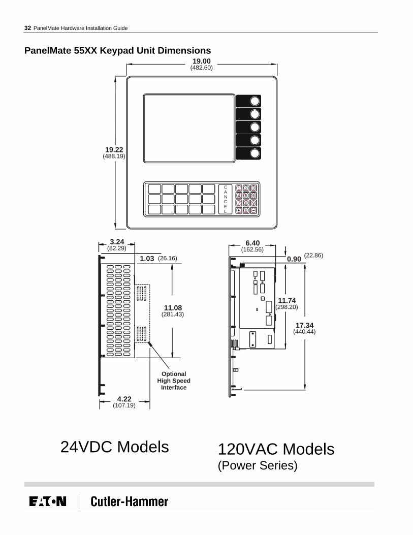
PanelMate 55XX Keypad Unit Dimensions 19.00
6.40
0.90
11.74
17.34
19.22
(482.60)
(162.56)(22.86)
(298.20)
(440.44)
(488.19)
1CANCEL
2
5 64
7 8
0
9
3
3.24
4.22
11.08
1.03(82.29)
(107.19)
(281.43)
(26.16)
OptionalHigh Speed
Interface
24VDC Models 120VAC Models (Power Series)

Appendix A: Cutout and Unit Dimensions 33
PanelMate 57XX Keypad Unit Dimensions
4 5 6N
EL
C 7
0
8 9
CA
1 2 3
19.22
19.00
OPTIONAL
INTERFACEHIGH SPEED
3.84
4.81
11.08
1.03
AC POWERSUPPLY
OPTIONAL
5.15

34 PanelMate Hardware Installation Guide
PanelMate 55XX/57XX Keyboard Cutout Dimensions
Cutout
4.00
4.00
4.13
8.87
8.87
9.27
8.70
2.50 2.50
8.707.50 7.50
9.27
9.16 9.16
4.13
(101.60)
(101.60)
(104.90)
(225.30)
(225.30)
(235.46)
(220.98)
(63.50) (63.50)
(220.98)(190.50) (190.50)
(235.46)
(232.66) (232.66)
(104.90)
.25 Dia. Hole(6.35)

Appendix A: Cutout and Unit Dimensions 35
PanelMate 52XX Split Architecture Unit Dimensions
11.75
1.08
(298.45)
(27.43)
13.96
5.22
0.05 (Ref.)
19.00
6.40
(354.58)
(132.59)
(1.27)
(482.60)
(162.56)3.24
11.08
1.21(82.29)
(281.43)
(30.73)
OptionalHigh Speed
Interface
4.22(107.19)
24VDC Models 120VAC Models (Power Series)

36 PanelMate Hardware Installation Guide
PanelMate 54XX Split Architecture Unit Dimensions
5
0
8
2
4
7
1
6
9
3
5.22
19.00
13.96
.05
(REF)
CANCEL
OPTIONALHIGH SPEEDINTERFACE
1.21
11.08
4.81
3.84
SUPPLY
OPTIONALAC POWER
5.15

Appendix A: Cutout and Unit Dimensions 37
PanelMate 52XX/54XX Split Architecture Cutout Dimensions
Cutout
Cutout
5.005.00
1.66
1.13
1.13
1.19
2.00
3.50
3.50
1.00
5.00 2.50 2.50 5.00
8.80 8.801.66 1.66
6.22
6.22
1.00
2.00
1.19
1.66
2.13
8.82
9.7527.00
MinimumMaximum
8.82
2.13
2.50 2.50(127.00)(127.00)
(42.16)
(28.70)
(28.70)
(30.23)
(50.80)
(88.90)
(88.90)
(25.40)
(127.00) (63.50) (63.50) (127.00)
(223.52) (223.52)(42.16) (42.16)
(157.99)
(157.99)
(25.40)
(50.80)
(30.23)
(42.16)
(54.10)
(224.03)
(247.65)(685.80)
(224.03)
(54.10)
(63.50) (63.50)
.22 Dia. Hole(5.59)
.25 Dia. Hole(6.35)
.25 Dia. Slot(6.35)
38 PanelMate Hardware Installation Guide
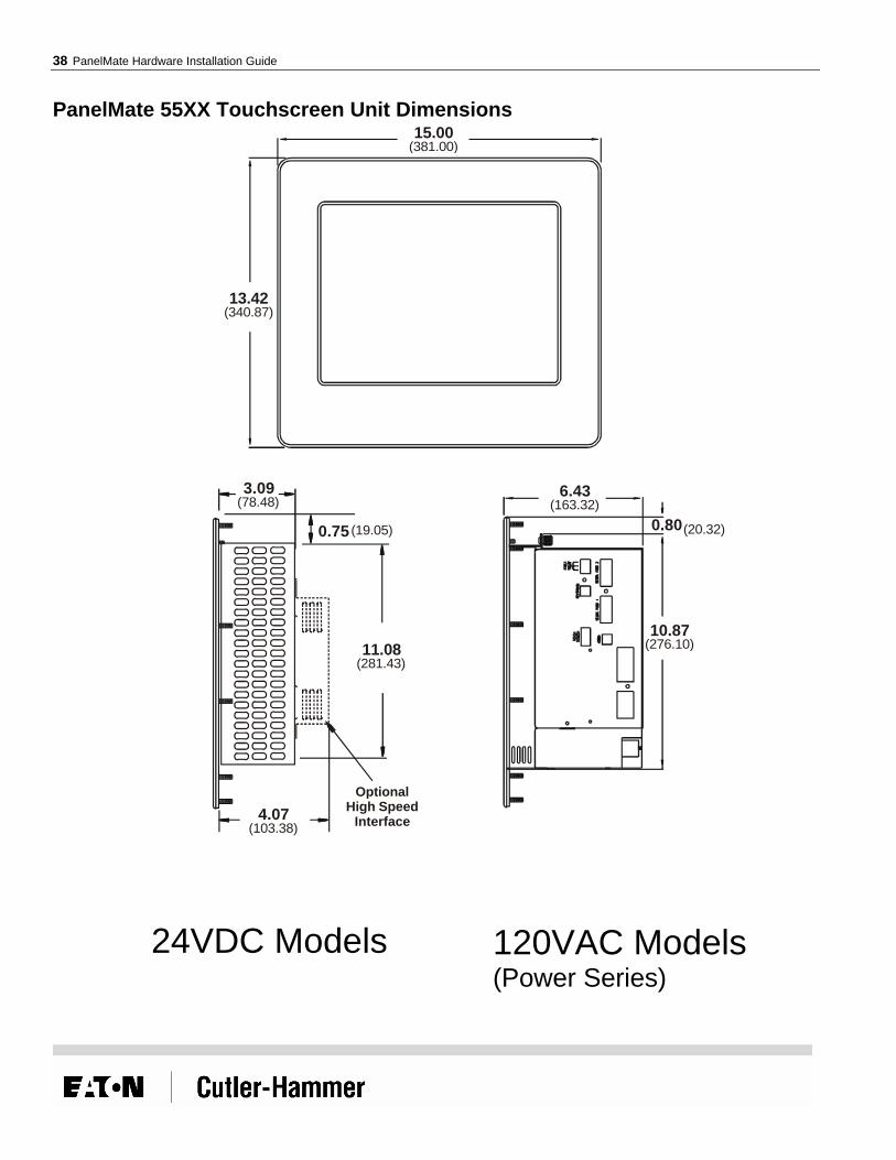
PanelMate 55XX Touchscreen Unit Dimensions 15.00
10.87
6.43
0.80
13.42
(381.00)
(276.10)
(163.32)
(20.32)
(340.87)
3.09
4.07Optional
High SpeedInterface
11.08
0.75
(78.48)
(103.38)
(281.43)
(19.05)
24VDC Models 120VAC Models (Power Series)

Appendix A: Cutout and Unit Dimensions 39
PanelMate 57XX Touchscreen Unit Dimensions
HIGH SPEED
INTERFACE
OPTIONAL
11.08
0.75
3.694.66
SUPPLY
OPTIONAL
AC POWER
5.00
13.42
15.00

40 PanelMate Hardware Installation Guide
PanelMate 55XX/57XX Touchscreen Cutout Dimensions
Cutout
13.80
12.52
6.37
6.37
1.75
1.75
5.25
5.256.26
7.167.165.505.50
1.901.90
6.90
(350.52)
(318.01)
(161.80)
(161.80)
(44.45)
(44.45)
(133.35)
(133.35)(159.00)
(181.86)(181.86)
(139.70)(139.70)
(48.26)(48.26)
(175.26)
.25 Dia. Slot(6.35)
.25 Dia. Hole(6.35)

Appendix A: Cutout and Unit Dimensions 41
PanelMate 4000 Keypad Unit Dimensions
1CANCEL
2
5 64
7 8
0
9
3
19.22
19.00
17.26
15.50
0.96
(488.19)
(482.60)
(438.04)
(393.70)
(24.38)

42 PanelMate Hardware Installation Guide
PanelMate 4000 Keypad Cutout Dimensions
Cutout
4.00
4.00
4.13
8.87
8.87
9.27
8.70
2.50 2.50
8.707.50 7.50
9.27
9.16 9.16
4.13
(101.60)
(101.60)
(104.90)
(225.30)
(225.30)
(235.46)
(220.98)
(63.50) (63.50)
(220.98)(190.50) (190.50)
(235.46)
(232.66) (232.66)
(104.90)
.25 Dia. Hole(6.35)

Appendix A: Cutout and Unit Dimensions 43
PanelMate 4000 Split Architecture Unit Dimensions
12.06
0.92
(306.32)
(23.37)
13.96
5.22
0.05 (Ref.)
19.00
15.50
(354.58)
(132.59)
(1.27)
(482.60)
(393.70)

44 PanelMate Hardware Installation Guide
PanelMate 4000 Split Architecture Cutout Dimensions
Cutout
Cutout
5.005.00
1.66
1.13
1.13
1.19
2.00
3.50
3.50
1.00
5.00 2.50 2.50 5.00
8.80 8.801.66 1.66
6.22
6.22
1.00
2.00
1.19
1.66
2.13
8.82
9.7527.00
MinimumMaximum
8.82
2.13
2.50 2.50(127.00)(127.00)
(42.16)
(28.70)
(28.70)
(30.23)
(50.80)
(88.90)
(88.90)
(25.40)
(127.00) (63.50) (63.50) (127.00)
(223.52) (223.52)(42.16) (42.16)
(157.99)
(157.99)
(25.40)
(50.80)
(30.23)
(42.16)
(54.10)
(224.03)
(247.65)(685.80)
(224.03)
(54.10)
(63.50) (63.50)
.22 Dia. Hole(5.59)
.25 Dia. Hole(6.35)
.25 Dia. Slot(6.35)

Appendix A: Cutout and Unit Dimensions 45
PanelMate 4000 Touchscreen Unit Dimensions
17.26
15.50
0.96
(438.04)
(393.70)
(24.38)
15.00
13.42
17.94
4.52
10.262.372.37
(381.00)
(340.87)
(455.68)
(114.81)
(260.60)
(60.20)(60.20)

46 PanelMate Hardware Installation Guide
PanelMate 4000 Touchscreen Cutout Dimensions
Cutout
13.80
12.52
6.37
6.37
1.75
1.75
5.25
5.256.26
7.167.165.505.50
1.901.90
6.90
(350.52)
(318.01)
(161.80)
(161.80)
(44.45)
(44.45)
(133.35)
(133.35)(159.00)
(181.86)(181.86)
(139.70)(139.70)
(48.26)(48.26)
(175.26)
.25 Dia. Slot(6.35)
.25 Dia. Hole(6.35)

Appendix A: Cutout and Unit Dimensions 47
PanelMate 3000 Keyboard Unit Dimensions 13.50
13.00
(342.90)
(330.20)
0.655.15
11.75
(16.51)(130.81)
(298.45)
3.00
3.98
8.75
0.60(76.20)
(222.25)
(15.24)
OptionalHigh Speed
Interface
(101.09)
24VDC Models 120VAC Models

48 PanelMate Hardware Installation Guide
PanelMate 3000 Keypad Cutout Dimensions
Cutout
.22 Dia. Hole(5.59)
.22 Dia. Slot(5.59)
6.25
6.22
6.22
6.47
1.50 1.50
6.47
4.50 4.50
6.00
6.00
12.00
4.50
4.50
6.25
12.50
(158.75)
(157.99)
(157.99)
(164.34)
(38.10) (38.10)
(164.34)
(140.46) (140.46)
(152.40)
(152.40)
(304.80)
(140.46)
(140.46)
(158.75)
(317.50)
1.50
1.50
(38.10)
(38.10)

Appendix A: Cutout and Unit Dimensions 49
PanelMate 3000 Touchscreen Unit Dimensions
11.97
1.21
10.22
5.40
5.14
12.30
(304.04)
(30.73)
(259.59)
(137.16)
(130.56)
(312.42)
2.90
3.88
8.75
1.61
(73.66)
(222.25)
(40.89)
(98.55)
OptionalHigh Speed
Interface
24VDC Models 120VAC Models
50 PanelMate Hardware Installation Guide
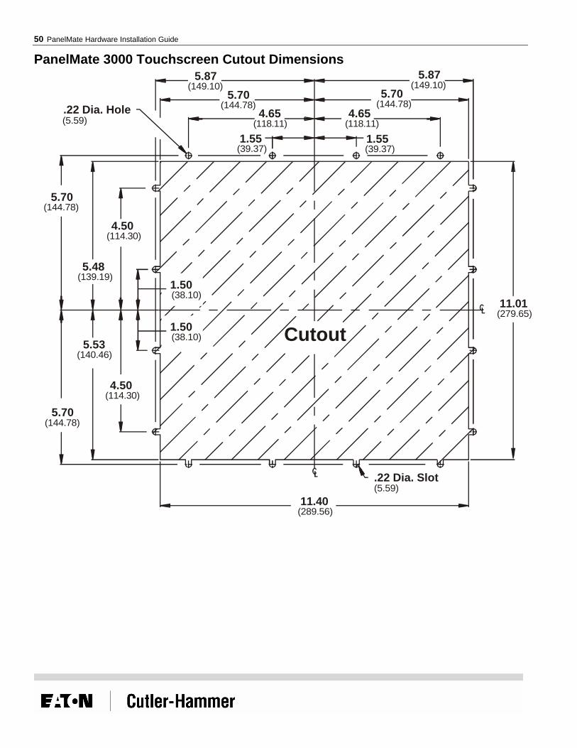
PanelMate 3000 Touchscreen Cutout Dimensions
.22 Dia. Slot
.22 Dia. Hole
11.40
11.01
5.875.87
5.705.70
5.70
5.48
4.50
4.50
5.53
5.70
4.65
1.55 1.55
4.65
(5.59)
(5.59)
(289.56)
(279.65)
(149.10)(149.10)
(144.78)
(144.78)
(139.19)
(114.30)
(114.30)
(140.46)
(144.78)
(118.11)
(39.37) (39.37)
(118.11)
(144.78)
Cutout
1.50
1.50
(38.10)
(38.10)

Appendix A: Cutout and Unit Dimensions 51
PanelMate 2000 Model 26xx Keyboard Unit Dimensions 11.50
13.10
11.80
10.529.84
0.68
(292.10)
(332.74)
(299.72)
(267.21)(249.94)
(17.27)

52 PanelMate Hardware Installation Guide
PanelMate 2000 Model 26xx Keyboard Cutout Dimensions
12.10
6.05
1.501.50
5.475.47
6.27
6.27
4.504.50
.22 Dia. Slot.22 Dia. Hole5.31
10.62
(146.41)
(153.67)
(38.10)(38.10)
(138.94)(138.94)
(159.26)
(159.26)
(114.30)(114.30)
(5.59)(5.59)(134.87)
(269.75)
1.65
4.95
4.95
1.65
(41.91)
(125.73)
(125.73)
(41.91) Cutout

Appendix A: Cutout and Unit Dimensions 53
PanelMate 2000 Model 24xx Keyboard Unit Dimensions 11.50
12.00
10.72
10.489.80
0.66
(292.10)
(304.80)
(272.29)
(266.19)(248.92)
(16.76)

54 PanelMate Hardware Installation Guide
PanelMate 2000 Model 24xx Keyboard Cutout Dimensions
10.62
5.72
4.50
1.50
1.50
4.50
4.50
1.50 1.50
4.50
5.72
5.47 5.47
5.31
5.50
11.00
(269.75)
(145.29)
(114.30)
(38.1)
(38.1)
(114.30)
(114.30)
(38.10) (38.10)
(114.30)
(145.29)
(138.94) (138.94)
(134.87)
(139.70)
(279.40)
.22 Dia. Slot(5.59)
.22 Dia. Hole(5.59)
Cutout

Appendix A: Cutout and Unit Dimensions 55
PanelMate 1100/1700 Keyboard Unit Dimensions
11.00
12.00
(279.40)
(304.80)
2.75(69.85)
1.66
1.10
3.73
4.20
6.36
(42.16)
(27.94)
(94.74)
(106.68)
(161.54)
OptionalHigh Speed
Interface

56 PanelMate Hardware Installation Guide
PanelMate 1100/1700 Keyboard Cutout Dimensions
5.00
10.00
11.00
5.50
4.00
4.00 4.00
5.705.70
4.00
5.20
5.20(127.00)
(254.00)
(279.40)
(139.70)
(101.60)
(101.60) (101.60)
(144.78)(144.78)
(101.60)
(132.08)
(132.08)
Cutout
.201 Dia. Hole(5.11)

Appendix A: Cutout and Unit Dimensions 57
PanelMate 1100/1700 Touchscreen Unit Dimensions
7.63
10.51
(193.80)
(266.95)
2.75(69.85)
3.73(94.74)
4.20
0.63
6.36
(106.68)
(17.27)
(161.54)
OptionalHigh Speed
Interface

58 PanelMate Hardware Installation Guide
PanelMate 1100/1700 Touchscreen Cutout Dimensions
Cutout
4.91 4.91
6.50
9.384.69
1.65
1.50
3.47
3.47
3.25
3.26 3.26
(124.71) (124.71)
(165.10)
(238.25)(119.13)
(41.91)
(38.10)
(88.14)
(88.14)
(82.55)
(82.80) (82.80)
.187 Dia. Hole(4.75)

Appendix A: Cutout and Unit Dimensions 59
PanelMate 1500 Keyboard Unit Dimensions
11.00
12.00
(279.40)
(304.80)
2.50(63.50)
1.66
1.10
3.48
4.20
6.36
(42.16)
(27.94)
(88.39)
(106.68)
(161.54)
OptionalHigh Speed
Interface

60 PanelMate Hardware Installation Guide
PanelMate 1500 Keyboard Cutout Dimensions
5.00
10.00
11.00
5.50
4.00
4.00 4.00
5.705.70
4.00
5.20
5.20(127.00)
(254.00)
(279.40)
(139.70)
(101.60)
(101.60) (101.60)
(144.78)(144.78)
(101.60)
(132.08)
(132.08)
Cutout
.201 Dia. Hole(5.11)

Appendix A: Cutout and Unit Dimensions 61
PanelMate 1500 Touchscreen Unit Dimensions
7.63
10.51
193.80
266.95
2.48(62.99)
3.47(88.14)
4.20
0.63
6.37
(106.68)
(17.27)
(161.80)
OptionalHigh Speed
Interface
62 PanelMate Hardware Installation Guide
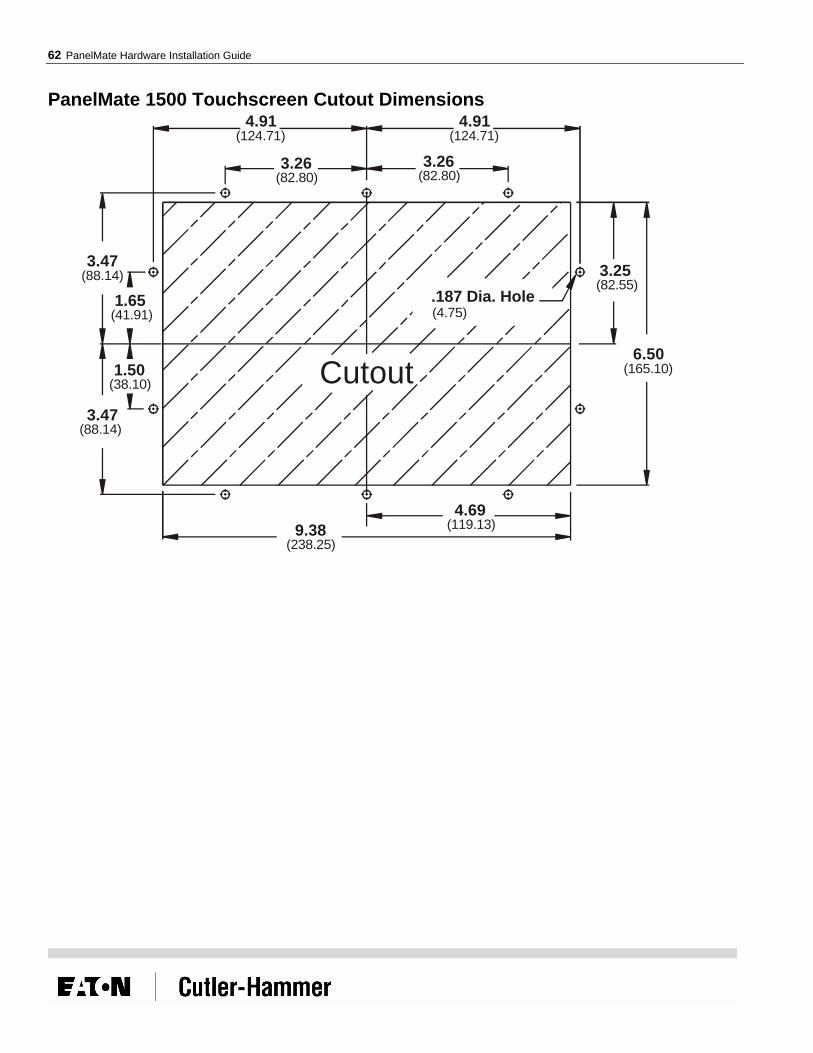
PanelMate 1500 Touchscreen Cutout Dimensions
Cutout
4.91 4.91
6.50
9.384.69
1.65
1.50
3.47
3.47
3.25
3.26 3.26
(124.71) (124.71)
(165.10)
(238.25)(119.13)
(41.91)
(38.10)
(88.14)
(88.14)
(82.55)
(82.80) (82.80)
.187 Dia. Hole(4.75)

Index 63
Index A
Allen-Bradley Data Highway/Data Highway Plus Communications, 21
Allen-Bradley DH-485 Communications, 20 Allen-Bradley Remote I/O Link Communications, 22
C Cable Placement, 29 Cable Segregation, 28 Connectivity Options, 11
D DeviceNet Communications, 25
E Enclosure Construction, 10 Enclosure Rating, 10 Enclosure Size vs. Average Internal Temperature Rise, 13 Enclosure Sizing and Unit Positioning, 10
G GE Fanuc Genius I/O Communications, 23
M Modicon Modbus Plus Communications, 24
P Potential Problem Areas, 11 Power and Ground Instructions, 16 Profibus DP Communications, 26
R Replacing a 120VAC PanelMate Power Series unit with a 24VDC
PanelMate Power Pro/Pro LT unit, 31 Replacing a 120VAC PanelMate Power Series unit with another
120VAC PanelMate Power Series unit., 31 Replacing Existing PanelMate Power Series Units, 8 RS-232 Communications, 17 RS-422 Communications, 18 RS-485 Multi-Drop Communications, 19
T The Three Most Critical Installation Issues, 7
U Upgrading a PanelMate Power Series Model 1500 unit with a
PanelMate Power Pro Model 1700 or Pro LT Model 1100 unit, 32

Reader Comment Card Cutler-Hammer strives to provide quality user guides and product manuals. Please take a moment to fill out this comment card.
Title: PanelMate Hardware Installation Guide 01-00436-06 Excellent Good Fair Poor
Is the document easy to follow?
Does the product work as described in this document?
Are the instructions easy to follow?
Are the examples helpful/useful?
Are there enough examples?
Is the document organized logically?
Is it easy to find what you are looking for?
Are the illustrations clear and useful?
How would you improve this document?
Please list any errors found in this document:
Other comments:
Your name and address: (optional)
Thank you for your comments. Please fax this page to:
Cutler-Hammer Technical Publications Dept.
FAX : 614-882-0417