CIS224 Software Projects: Software Engineering and Research Methods
Upload
nguyenduongCategory
view
224download
0
Panel Methods: Software and Applications

Outline• Some Potential Theory• Derivation of the Integral Equation for the Potential• Classic Panel Method• 2-D
– Software: PANEL ,POBLO, Xfoil– Application: Subsonic Airfoil Aerodynamics
• 3-D– Issues in the Problem formulation for 3D flow over aircraft– Advanced panel methods– Software: PanAir and CMARC – Example applications
• Summary: using panel methods

Program PANEL• Description of PANEL
– An exact implementation of the classic method (2D)
– Including a subroutine to generate the ordinates for the NACA 4-digit and 5-digit airfoils
– The main drawback is the requirement for a trailing edge thickness that’s exactly zero.
– The node points are distributed employing the widely used cosine spacing function.

• Study on the convergence– Sensitivity of the solution (Cd, Cl, Cm) to
the number of panels
Change of drag with number of panels

Change of lift with number of panels

Change of pitching moment with the inverse of the number of panels
Conclusion:Results are relatively insensitive to the number of panels once fifty or sixty panels are used.
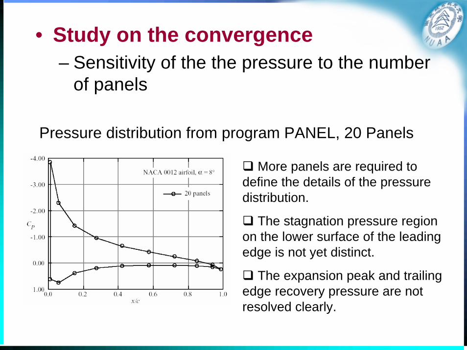
• Study on the convergence– Sensitivity of the the pressure to the number
of panels
Pressure distribution from program PANEL, 20 Panels
More panels are required to define the details of the pressure distribution.
The stagnation pressure region on the lower surface of the leading edge is not yet distinct.
The expansion peak and trailing edge recovery pressure are not resolved clearly.

Pressure distribution from progrm PANELcomparing results using 20 and 60 panels.
It appears that the pressure distribution is well defined with 60 panels.

Pressure distribution from program PANELcomparing results using 60 and 100 panels.
It is almost impossible to identify the differences between the 60 and 100 panel.

• Validation– Comparison of results with an exact solution
Comparison of results from PANEL with an essentially exact mapping solution for the NACA 4412 airfoil at 6° angle-of-attack.

• Validation– Investigation of the agreement with experimental data.
Comparison of PANEL lift predictions with experimental data
Agreement is good at low angles of attack, where the flow is fully attached.
The agreement deteriorates as the angle of attack increases, and viscous effects start to show up as a reduction in lift with increasing angle of attack, until, finally, the airfoil stalls.

Comparison of PANEL moment predictions with experimental data
The computed location of the aerodynamic center, dCm / dCL = 0 , is not exactly at the quarter chord, although the experimental data is very close to this value.
The uncambered NACA 0012 data shows nearly zero pitching moment until flow separation starts to occur.
The cambered airfoil shows a significant pitching moment, and a trend due to viscous effects that is exactly opposite the computed prediction.

Comparison of pressure distribution from PANEL with data
In general the agreement is very good.
The primary area of disagreement is at the trailing edge. Here viscous effects act to prevent the recovery of the experimental pressure to the levels predicted by the inviscid solution.
2
211
2
pp p vC
vvρ∞
∞∞
⎛ ⎞−= = − ⎜ ⎟
⎝ ⎠

• Limitation – Panel methods often have trouble with
accuracy at the trailing edge of airfoils with cusped trailing edges, so that the included angle at the trailing edge is zero.

PANEL Performance near the airfoil trailing edge
Comparison at the trailing edge of 6- and 6A-series airfoil geometries

Introduction to PABLO
Potential flow around Airfoils with Boundary Layer coupled One-way
KTH- The Royal Institute of Technology Department of Aeronautics
Stockholm, Sweden Programmed by Christian Wauquiez, 1999

Program PABLO description• A low-speed airfoil analysis program written in MATLAB
• Using one way coupled inviscid + boundary layer model
• The inviscid flow is solved using a Panel Method. Three different kinds of singularity distributions can be used.
– Constant-strength sources
– Constant-strength doublets
– Linear vortices
• Three different kinds of geometries are implemented
– Ellipse with prescribed axis ratio
– NACA 4 digits airfoil library
– General airfoil library

Program PABLO description
• The boundary layer equations– Thwaites' equations for the laminar part of the flow
– Head's equations for the turbulent part
– Michel's criterion is used to locate transition
– The drag coefficient is computed using the Squire-Young formula
• The solution computed by the program– The Cp distribution
– The aerodynamics coefficients CL, CD and CM
– The coordinate of the center of pressure Xcp
– The location of transition and eventual laminar or turbulent separation
– The distribution of the boundary layer parameters

PABLO

Introduction to XFOIL
• XFOIL is a software which goal was to combine the speed and accuracy of high-order panel methods with the new fully-coupled viscous/inviscid interaction methods.
• It was developed by Dr. Mark Drela, MIT and Harold Youngren, Aerocraft, Inc.
• It consists of a collection of menu-driven routines which perform various useful functions.– “Profili”, which is based on Xfoil, has a nice interface

Introduction to XFOIL
• Functions– Viscous (or inviscid) analysis of an existing airfoil
– Airfoil design and redesign by interactive specification of a surface speed distribution via screen cursor or mouse.
– Airfoil redesign by interactive specification of new geometric parameters
– Blending of airfoils
– Drag polar calculation with fixed or varying Reynolds and/or Mach numbers.
– Writing and reading of airfoil geometry and polar save files
– Plotting of geometry, pressure distributions, and polar.

Subsonic Airfoil Aerodynamics
• Tool– PANEL: Means of easily examining the pressure
distributions, and forces and moments for different airfoil shapes.
• What are we going to investigate ?
Airfoil shapeAirfoil shape Pressure DistributionsPressure
Distributions PerformancePerformance
we must first investigate the close relation between the airfoil geometry to the pressure distribution.

Key areas of interest when examining airfoil pressure distributions

• Overview of Airfoil Characteristics– Drag
– Lift• The slope of the lift curve
– Thin airfoil theory predicts that the lift curve slope should be 2π
– Thick airfoil theory says that it should be slightly greater than 2π, with 2π being the limit for zero thickness.
• Zero-lift angle
– Moment• Thin airfoil theory predicts that subsonic airfoils have their
aerodynamic centers at the quarter chord for attached flow.
• The value of Cm0 depends on the camber

• Investigation of Airfoil Pressure Distributions– Uncambered airfoils
The α = 0° case produces a mild expansion around the leading edge followed by a monotonic recovery to the trailing edge pressure.
As the angle of attack increases the pressure begins to expand rapidly around the leading edge, reaching a very low pressure, and resulting in an increasingly steep pressure recovery at the leading edge.
Effect of angle of attack on the pressure distribution

Comparison of NACA 4-digit airfoils of 6, 12, and 18% thicknesses

Effect of airfoil thickness on the pressure distribution at zero lift
The thicker airfoil produces a larger disturbance, and lower minimum pressure.

Effect of airfoil thickness on the pressure distribution at CL = 0.48
The thinnest airfoil shows a dramatic expansion and recompression.
The thicker airfoil results in a significantly milder expansion and subsequent recompression.

• Investigation of Airfoil Pressure Distributions– Cambered airfoils
Comparison of uncambered and cambered NACA 4-digit airfoils

Effect of angle of attack on cambered airfoil pressure distributions at low lift
The role of camberObtaining lift without producing a leading edge expansionReducing the possibility of leading edge separation

Camber effects on airfoil pressure distributionsat CL = 0.48

Camber effects on airfoil pressure distributionsat CL = 0.96
Distribution is very different !
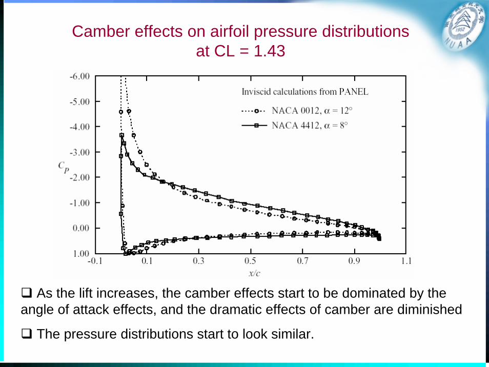
Camber effects on airfoil pressure distributions at CL = 1.43
As the lift increases, the camber effects start to be dominated by the angle of attack effects, and the dramatic effects of camber are diminished
The pressure distributions start to look similar.

The effect of extreme aft camber

Comments on airfoil with extreme aft camber
• This is part of the design strategy of Whitcomb when the so-called NASA supercritical airfoils were developed.
• The aft camber “opens up” the pressure distribution near the trailing edge.
• Two adverse properties– the large zero lift pitching moment
– the delayed and then rapid pressure recovery on the upper surface
• This type of pressure recovery is a very poor way to try to achieve a significant pressure recovery because the boundary layer will separate early.

An advanced airfoil: GA(W)-1 airfoil
• 17% thick airfoil• Providing better maximum lift and stall
characteristics

Pressure distribution at zero angle of attack of the GA(W)-1
• The upper surface pressure distribution reaches a constant pressure plateau, and then has a moderate pressure recovery.
• Aft camber is used to obtain lift on the lower surface and “open up” the airfoil pressure distribution near the trailing edge.

Geometry and Design
• Effects of Shape Changes on Pressure Distributions– Shape changes
• camber and thickness.
• local modifications to the airfoil surface
• small deflections of the trailing edge
• Shape for a specified pressure distribution– The inverse problem
• The aerodynamic designer wants to find the geometric shape corresponding to a prescribed pressure distribution from scratch.

Airfoil analysis and design

Inverse Methods

Homework 3• Study on the convergence using PABLO/XFoil
– Sensitivity of the solution (Cl, Cm) to the number of panels
• Validation on PABLO/Xfoil– Compare Cl, Cm from PABLO/Xfoil with the experiment data
• Study on the airfoil aerodynamics– Camber effects on airfoil pressure distributions at same angle of
attack
– Camber effects on airfoil pressure distributions at same lift coefficient
– Camber effects on the angle of attack at which lift is zero

Issues in the problem formulation for 3D flow over aircraft
• The proper treatment of wing tips
• The treatment of the wake
• The fuselage aft of the wing
• No leakage in the panel model representation of the surface
• The outward surface normal is oriented in the proper direction
• All surface are properly enclosed
• Wakes are properly specified– Handled automatically
– Precisely specified by the user

Wing-body-tail configuration panel scheme with wakes

Advanced Panel Methods
• What is a “Higher Order” Panel Method?– using singularity distributions that are not constant on the panel
– using panels which are non-planar
• Why is “Higher Order” Panel Method needed ?– Be crucial in obtaining accurate solutions for the Prandtl-
Glauert Equation at supersonic speeds.
– Good results can be obtained using far fewer panels with higher order methods.

Today’s Standard Programs
• A brief review– Panel methods are widely used in the aircraft industry,
and have been for a long time.
– All the new professionally-developed codes work well.
– The selection of a specific code will likely be based on non-technical considerations.

Today’s Standard Programs
• Product Codes– PAN AIR
– VSAERO
– QUADPAN
– Version of the “Hess Codes”
– Woodward
– PMARC
– CMARC

PANAIR
• Boeing-developed code, funded by a variety of government agencies.
• It uses higher order panels, and is both subsonic and supersonic.
• It’s relatively expensive and difficult to run.
• To effectively use the code good pre- and post-processing systems must be available.

VSAERO• AMI developed (Analytical Mechanics Inc).• It uses low order panels and is subsonic only.• It handles general geometries, and includes options to
treat viscous effects and vortex flows.• Expensive
Panel Model of MD-11 in Ground Effect During Take Off Rotation
Example

QUADPAN
• Lockheed-developed, and possibly developed at some government labs.
• Not widely used by industry outside of Lockheed. – This is probably because of availability.

Version of the “Hess Codes”
• Further developments of the team at Douglas now led by Hess.
• Douglas uses this code exclusively.
• Douglas developed numerous versions under various government contracts

Woodward
• Woodward was a pioneer panel method developer
• Woodward went into business and continued to develop codes.
• USSAERO– developed under NASA contract
– treats both supersonic and subsonic flow

PMARC• The newest panel method code developed at NASA
Ames
• The code is a lower order panel method, and can simulate steady as well as unsteady flow.
• The wake position can be obtained as part of the solution.
• Providing an extremely flexible method to simulate a wide range of very general geometries
– simulation of high lift systems
– jet exhausts for VSTOL aircraft

• Example of application: Morphing Aircraft

control effectiveness contours

Personal Simulation WorkshopA Simulation Tool for Aerodynamic
Analysis and Design

Personal Simulation Workshop (PSW):Digital Wing Tunnel (DWT)
• PSW is a streamline-body design and analysis package for the PC, comprising programs for surface definition, flow analysis, and data visualization.
• Its three principal elements :– Loftsman
• geometric layout of external lines– Cmarc
• flow analysis– Postmarc
• interpretation of results

Introduction to Cmarc• An inviscid fluid flow analysis code of the type known as a low-
order panel method. – It is an enhanced version of NASA's Pmarc-12
• With modern desktop computers, dense meshes of 5,000 or more panels for a half-model can be analyzed in minutes.
• Although the basic analysis is inviscid, a subsequent boundary-layer analysis may be performed along individual streamlines or over the entire surface.– Provided that flow is attached and that large areas of crossflow do not
appear, the boundary layer analysis is quite accurate.
• Only the frictional and lift-induced components of drag can be computed, however; an inviscid analysis is inherently unable to calculate pressure or "form" drag.
• Written in ANSI C

Introduction to CmarcInterface


Displaying the Wake Using Postmarc

On-body streamlines
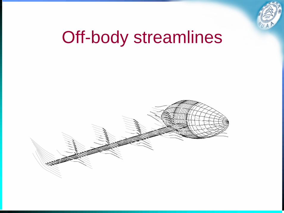
Off-body streamlines

Velocity Scan

Contouring Scan

F-15 example problem using Cmarc

Engine nacelle problem using Cmarc

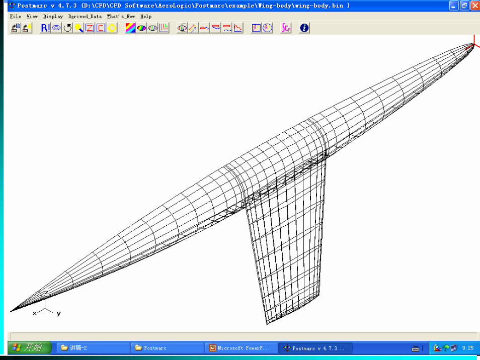
Delta wing-body using Cmarc

Peter Garrison's M2 Homebuilt

BD5 homebuilt using Cmarc

Wing with Flap Example Problem

GAW Airfoil Example Problem

Example applications of panel methods
• Evaluations of aerodynamic characteristics for aircraft configuration
• Effect of wing-tunnel walls
• America’s Cup designs
• Boeing 737 aerodynamic analysis
• Airship aerodynamic analysis

Evaluating the effect of the space shuttle on the Boeing 747
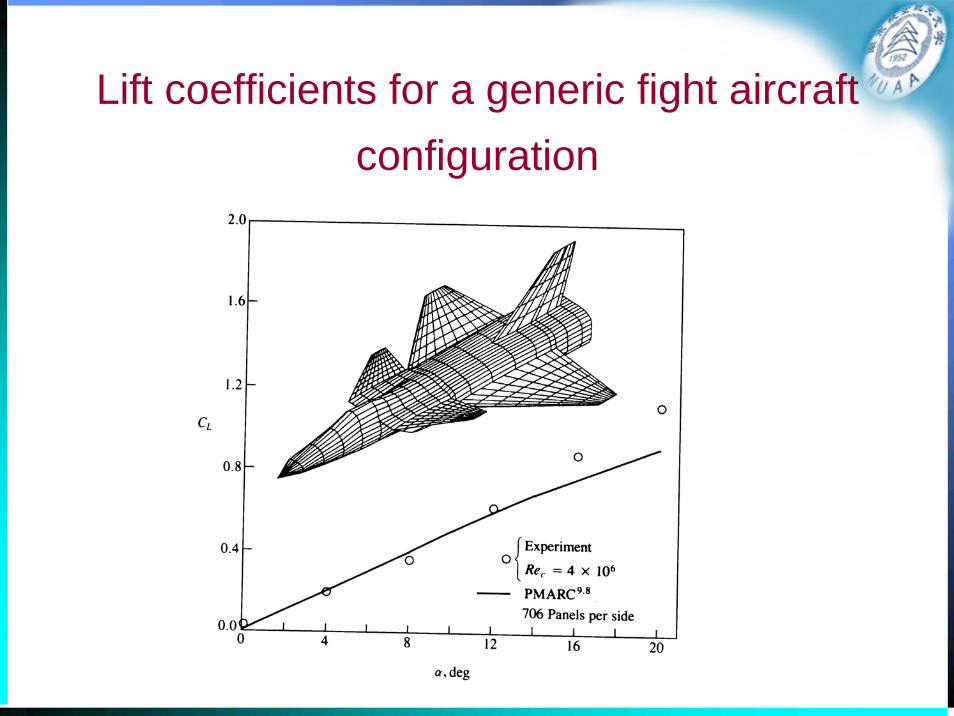
Lift coefficients for a generic fight aircraft configuration

Lift coefficients for the F/A-18

Effect of wing-tunnel walls on the distribution on the upper surface

America’s Cup designs
• Hull design• Free surface design

An example in some detail– Boeing 737-300
• Background– Modifications of 737-200 to 737-300 configuration
• The design of a new high lift system.• The design tool: PAN AIR

• Objective– understanding the wing flow-field for two different takeoff flap settings
• Flap 15 (normal): 2900 panels• Flap 1 (high altitude): 1750 panels
The panel representation of the 737-300 with 15° flap deflection

• Modeling– The computational models used 1750 panels for
flaps 1 and 2900 panels for flaps 15.
Inboard wing leading edge and nacelle details
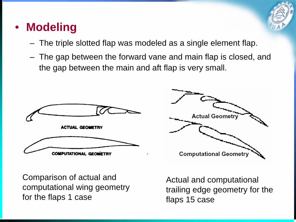
• Modeling– The triple slotted flap was modeled as a single element flap.
– The gap between the forward vane and main flap is closed, and the gap between the main and aft flap is very small.
Comparison of actual and computational wing geometry for the flaps 1 case
Actual and computational trailing edge geometry for the flaps 15 case

• Modeling– Spanwise discontinuity
Spanwise discontinuity details requiring modeling for flaps 1 case

• Modeling – The nacelle model
• The specification of the inlet flow at the engine face
• A model of the strut wake,
• The outer bypass air plume and the primary wake from the inner hot gas jet.

• Results: Spanwise distribution of lift coefficient
Flaps 1 case

In both cases the jig shape and flight shape including aeroelasticdeformation are included.
In both cases the shape including the deformation under load shows much better agreement with flight and wind tunnel data.
Notice the loss of lift on the wing at the nacelle station,and the decrease in lift outboard of the trailing edge flap location.
Flaps 15 case

• Results– The change in section lift coefficient with angle of attack
flaps 1 case

• The agreement between PAN AIR and flight test is better for the flaps 1 case.
• Viscous effects are becoming important for the flaps 15 case.
Flap 15 case

• Results: pressure distributions
Flap 1 case Flap 15 case
Comparison of pressure distributions between flight and computations

• Comments on results of pressure distributions– The flaps 1 case agreement is generally good.
– Calculations are presented for both the actual angle of attack, and the angle of attack which matches the lift coefficient.
– The flaps 15 case starts to show the problems that arise from these simplifications.
– This is a good example of the use of a panel method.

Airship aerodynamic analysis
Panel method was used to compute the aerodynamic pressure of a airship.
-1
-0.5
0
0.5
1

Using Panel Methods
• Common sense rules for panels– Vary the size of panels smoothly
• Panel placement and variation of panel size affect the quality of the solution.
• Extreme sensitivity of the solution to the panel layout is an indication of an improperly posed problem. If this happens, the user should investigate the problem thoroughly.
– Concentrate panels where the flowfield and/or geometry is changing rapidly.

• Cautions– You must use the results as a guide to help you develop your
own judgment.
– To get the most from the methods, you are required to have• An understanding of aerodynamics that provides an intuitive
expectation of the types of results
• An appreciation of how to relate your idealization to the real flow
• What a Panel Method Can't Do– Panel methods are inviscid solutions
• You will not capture viscous effects except via user “modeling” by changing the geometry.
– Solutions are invalid as soon as the flow develops local supersonic zones