TOSHIBA Satellite P200 - Satellite Pro P200 Series User's Manual Guide
PANACEA P200 DELRIN USER MANUAL
1
Basic Features
Delrin body with 1.75in outside diameter. Will fit into wells down to 2”
(schedule 80).
Has an internal chamber volume of 200mL.
Maximum depth below ground surface of 400ft.
Other Features
Compatible with Volume Booster for increased volume per cycle.
Compatible with Timer Control Unit for pump cycle automation.
Compatible with Zone Isolation Sampling Technology (ZIST).
Specifications
Delrin (PU-P-200-1000)
Body Construction Delrin Plastic
Length (in) 23.5
Outer Diameter (in) 1.75
Weight (lbs) 2
Maximum Pressure (psi) 200
Maximum Depth (ft bgs) 400
Minimum Submergence (ft) 6 ft with Volume Booster
Internal Volume (mL) 200
Standard Filter Pore Size (µm) 60, others available
Standard Tubing OD (in) 1/4, others available
Seal Material Buna-N
Gas Compatibility Nitrogen, Compressed Air
ZIST Compatibility 2” and 4”, requires adapter
Panacea P200 Precautions For Safe Use
1. Never disassemble the pump while it is connected to a pressurized source. 2. Never operate the pump past its specific maximum pressure. 3. Never use tube ferrules other than those provided by BESST INC. 4. Never disconnect the pump while it is pressurized with gas.
PANACEA P200 DELRIN USER MANUAL
2
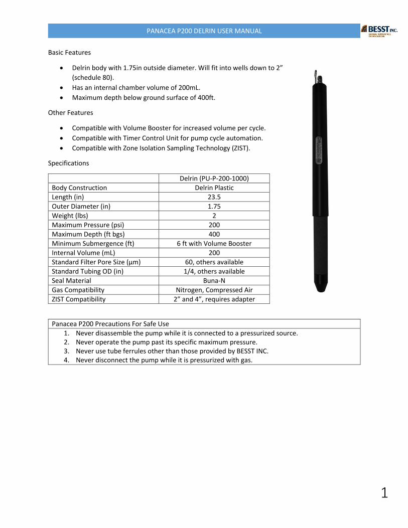
Panacea P200 Deployment Procedure
Step 1: Locate indented lettering on the top cap. The “G” signifies gas. The “S” signifies sample return. Connect gas tube to fitting with label “G” above it. Connect sample return tube to fitting with label “S” above it.
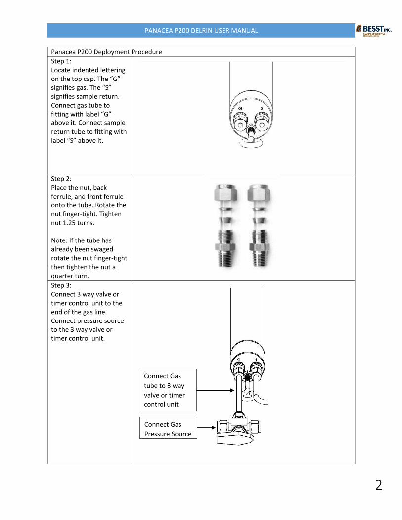
Step 2: Place the nut, back ferrule, and front ferrule onto the tube. Rotate the nut finger-tight. Tighten nut 1.25 turns. Note: If the tube has already been swaged rotate the nut finger-tight then tighten the nut a quarter turn. Step 3: Connect 3 way valve or timer control unit to the end of the gas line. Connect pressure source to the 3 way valve or timer control unit.
Connect Gas
Pressure Source
Connect Gas
tube to 3 way
valve or timer
control unit
PANACEA P200 DELRIN USER MANUAL
3
Step 4: Connect wire to deployment hook.
Step 5: Deploy pump and tubing down well pipe
Panacea P200 Downhole Operation
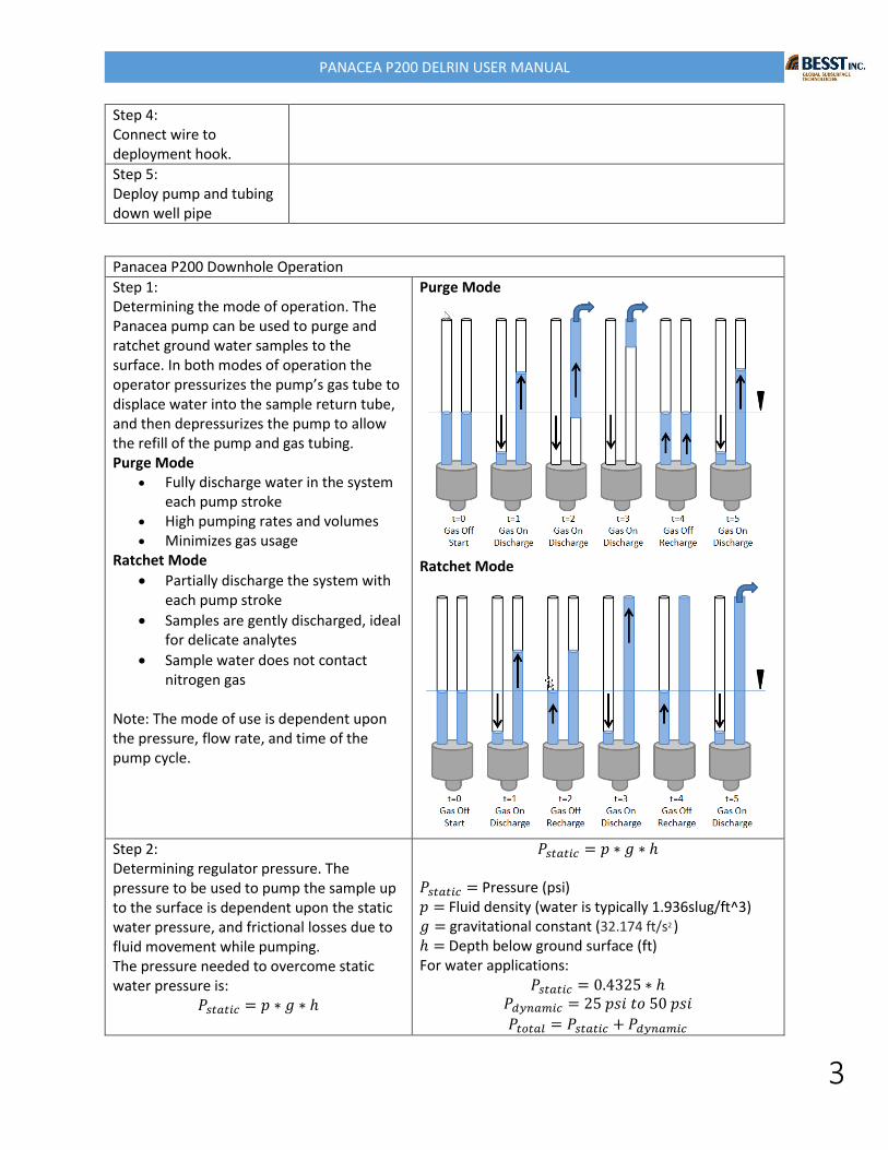
Step 1: Determining the mode of operation. The Panacea pump can be used to purge and ratchet ground water samples to the surface. In both modes of operation the operator pressurizes the pump’s gas tube to displace water into the sample return tube, and then depressurizes the pump to allow the refill of the pump and gas tubing. Purge Mode
Fully discharge water in the system each pump stroke
High pumping rates and volumes Minimizes gas usage
Ratchet Mode
Partially discharge the system with each pump stroke
Samples are gently discharged, ideal for delicate analytes
Sample water does not contact nitrogen gas
Note: The mode of use is dependent upon the pressure, flow rate, and time of the pump cycle.
Purge Mode
Ratchet Mode
Step 2: Determining regulator pressure. The pressure to be used to pump the sample up to the surface is dependent upon the static water pressure, and frictional losses due to fluid movement while pumping. The pressure needed to overcome static water pressure is:
𝑃𝑠𝑡𝑎𝑡𝑖𝑐 = 𝑝 ∗ 𝑔 ∗ ℎ
𝑃𝑠𝑡𝑎𝑡𝑖𝑐 = 𝑝 ∗ 𝑔 ∗ ℎ 𝑃𝑠𝑡𝑎𝑡𝑖𝑐 = Pressure (psi) 𝑝 = Fluid density (water is typically 1.936slug/ft^3) 𝑔 = gravitational constant (32.174 ft/s2 ) ℎ = Depth below ground surface (ft) For water applications:
𝑃𝑠𝑡𝑎𝑡𝑖𝑐 = 0.4325 ∗ ℎ 𝑃𝑑𝑦𝑛𝑎𝑚𝑖𝑐 = 25 𝑝𝑠𝑖 𝑡𝑜 50 𝑝𝑠𝑖
𝑃𝑡𝑜𝑡𝑎𝑙 = 𝑃𝑠𝑡𝑎𝑡𝑖𝑐 + 𝑃𝑑𝑦𝑛𝑎𝑚𝑖𝑐
PANACEA P200 DELRIN USER MANUAL
4
The pressure needed to overcome frictional losses is subjective to system setup. BESST INC. recommends that an additional pressure of 25psi to 50psi be added to the static water pressure to compensate for these frictional losses and help with the sealing of the foot valve poppet.
𝑃𝑑𝑦𝑛𝑎𝑚𝑖𝑐 = 25 𝑝𝑠𝑖 𝑡𝑜 50 𝑝𝑠𝑖
The pressure to be set on the regulator is the total pressure.
𝑃𝑡𝑜𝑡𝑎𝑙 = 𝑃𝑠𝑡𝑎𝑡𝑖𝑐 + 𝑃𝑑𝑦𝑛𝑎𝑚𝑖𝑐
In use the operator of the pump can adjust the dynamic pressure to achieve a specific flow rate.
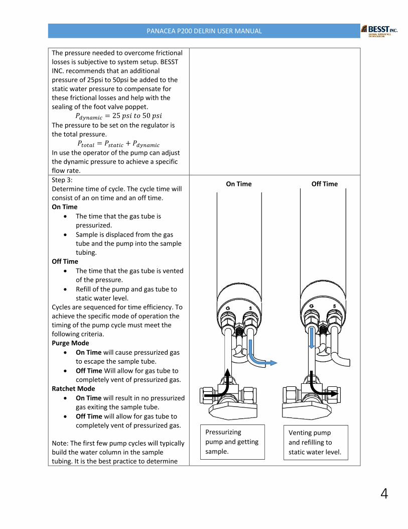
Step 3: Determine time of cycle. The cycle time will consist of an on time and an off time. On Time
The time that the gas tube is pressurized.
Sample is displaced from the gas tube and the pump into the sample tubing.
Off Time
The time that the gas tube is vented of the pressure.
Refill of the pump and gas tube to static water level.
Cycles are sequenced for time efficiency. To achieve the specific mode of operation the timing of the pump cycle must meet the following criteria. Purge Mode
On Time will cause pressurized gas to escape the sample tube.
Off Time Will allow for gas tube to completely vent of pressurized gas.
Ratchet Mode
On Time will result in no pressurized gas exiting the sample tube.
Off Time will allow for gas tube to completely vent of pressurized gas.
Note: The first few pump cycles will typically build the water column in the sample tubing. It is the best practice to determine
On Time Off Time
Pressurizing
pump and getting
sample.
Venting pump
and refilling to
static water level.
PANACEA P200 DELRIN USER MANUAL
5
timing cycles once the water column has been built to ground level.
Step 4: Refine pressure and timing intervals for optimum performance.
PANACEA P200 DELRIN USER MANUAL
6
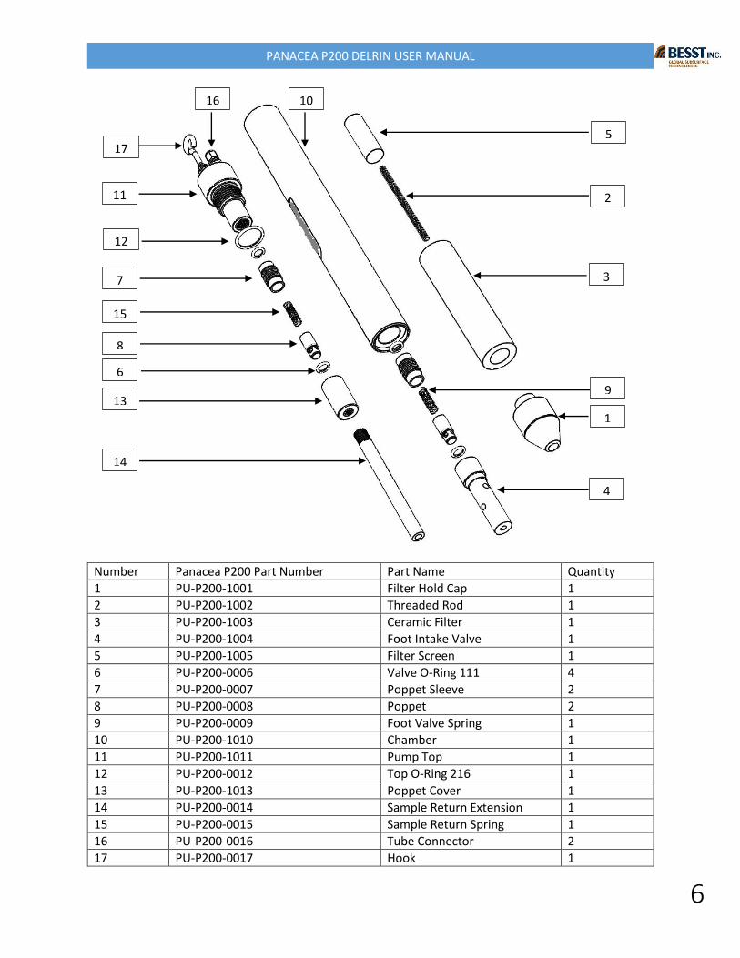
Number Panacea P200 Part Number Part Name Quantity
1 PU-P200-1001 Filter Hold Cap 1
2 PU-P200-1002 Threaded Rod 1
3 PU-P200-1003 Ceramic Filter 1
4 PU-P200-1004 Foot Intake Valve 1
5 PU-P200-1005 Filter Screen 1
6 PU-P200-0006 Valve O-Ring 111 4
7 PU-P200-0007 Poppet Sleeve 2
8 PU-P200-0008 Poppet 2
9 PU-P200-0009 Foot Valve Spring 1
10 PU-P200-1010 Chamber 1
11 PU-P200-1011 Pump Top 1
12 PU-P200-0012 Top O-Ring 216 1
13 PU-P200-1013 Poppet Cover 1
14 PU-P200-0014 Sample Return Extension 1
15 PU-P200-0015 Sample Return Spring 1
16 PU-P200-0016 Tube Connector 2
17 PU-P200-0017 Hook 1
11
12
7
15
8
6
13
14
5
2
3
1
9
4
16
17
10
PANACEA P200 DELRIN USER MANUAL
7
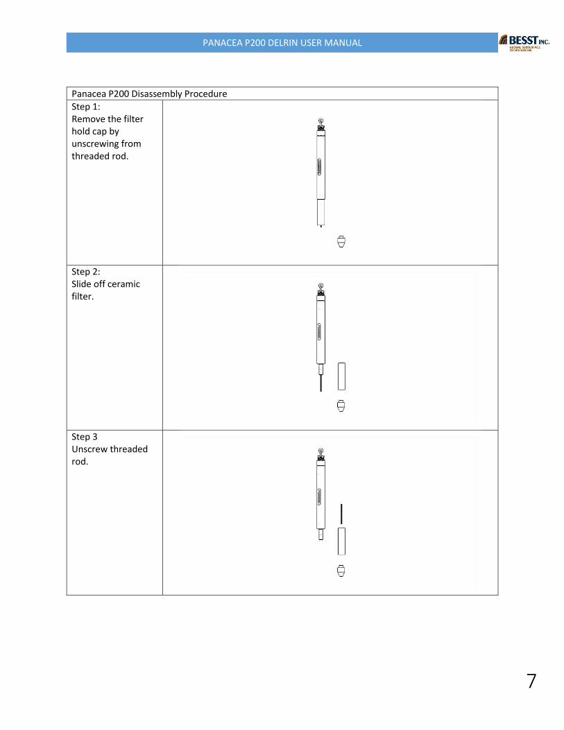
Panacea P200 Disassembly Procedure
Step 1: Remove the filter hold cap by unscrewing from threaded rod.
Step 2: Slide off ceramic filter.
Step 3 Unscrew threaded rod.
PANACEA P200 DELRIN USER MANUAL
8
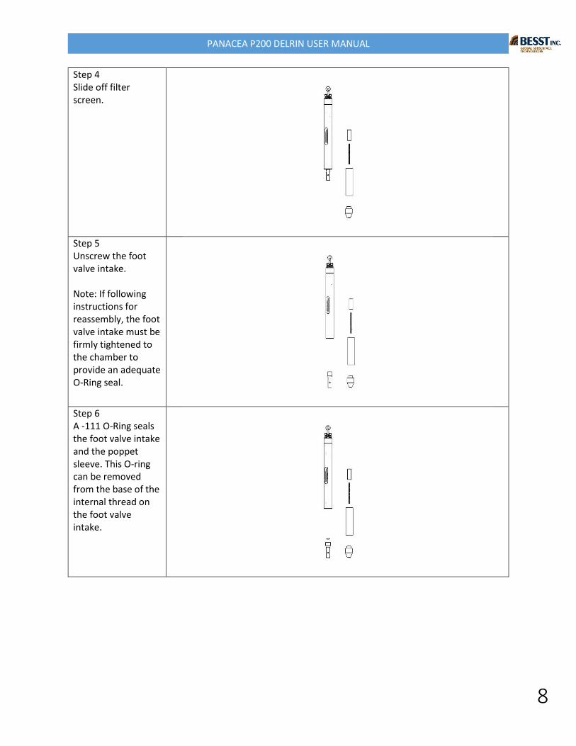
Step 4 Slide off filter screen.
Step 5 Unscrew the foot valve intake. Note: If following instructions for reassembly, the foot valve intake must be firmly tightened to the chamber to provide an adequate O-Ring seal.
Step 6 A -111 O-Ring seals the foot valve intake and the poppet sleeve. This O-ring can be removed from the base of the internal thread on the foot valve intake.
PANACEA P200 DELRIN USER MANUAL
9
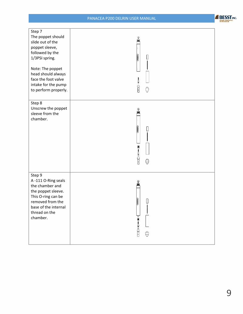
Step 7 The poppet should slide out of the poppet sleeve, followed by the 1/3PSI spring. Note: The poppet head should always face the foot valve intake for the pump to perform properly.
Step 8 Unscrew the poppet sleeve from the chamber.
Step 9 A -111 O-Ring seals the chamber and the poppet sleeve. This O-ring can be removed from the base of the internal thread on the chamber.
PANACEA P200 DELRIN USER MANUAL
10
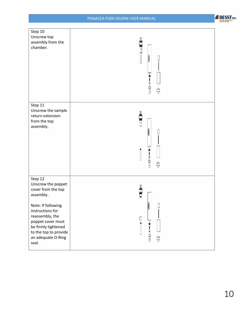
Step 10 Unscrew top assembly from the chamber.
Step 11 Unscrew the sample return extension from the top assembly.
Step 12 Unscrew the poppet cover from the top assembly. Note: If following instructions for reassembly, the poppet cover must be firmly tightened to the top to provide an adequate O-Ring seal.
PANACEA P200 DELRIN USER MANUAL
11
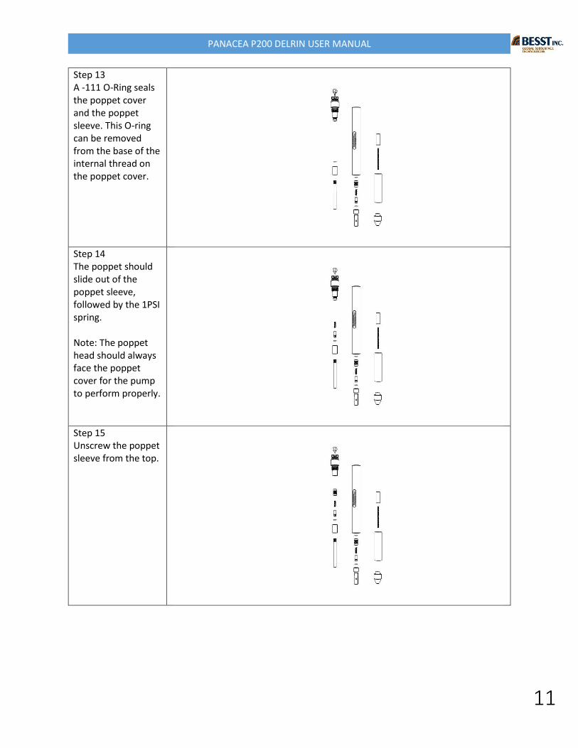
Step 13 A -111 O-Ring seals the poppet cover and the poppet sleeve. This O-ring can be removed from the base of the internal thread on the poppet cover.
Step 14 The poppet should slide out of the poppet sleeve, followed by the 1PSI spring. Note: The poppet head should always face the poppet cover for the pump to perform properly.
Step 15 Unscrew the poppet sleeve from the top.
PANACEA P200 DELRIN USER MANUAL
12
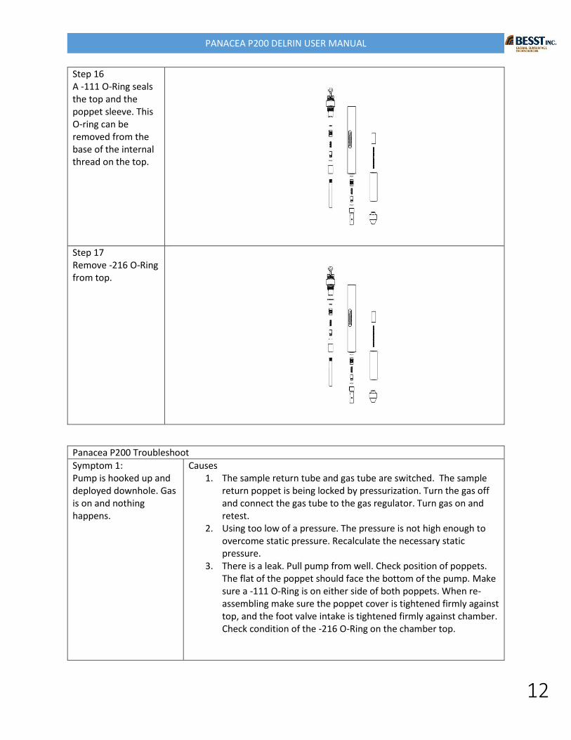
Step 16 A -111 O-Ring seals the top and the poppet sleeve. This O-ring can be removed from the base of the internal thread on the top.
Step 17 Remove -216 O-Ring from top.
Panacea P200 Troubleshoot
Symptom 1: Pump is hooked up and deployed downhole. Gas is on and nothing happens.
Causes 1. The sample return tube and gas tube are switched. The sample
return poppet is being locked by pressurization. Turn the gas off and connect the gas tube to the gas regulator. Turn gas on and retest.
2. Using too low of a pressure. The pressure is not high enough to overcome static pressure. Recalculate the necessary static pressure.
3. There is a leak. Pull pump from well. Check position of poppets. The flat of the poppet should face the bottom of the pump. Make sure a -111 O-Ring is on either side of both poppets. When re-assembling make sure the poppet cover is tightened firmly against top, and the foot valve intake is tightened firmly against chamber. Check condition of the -216 O-Ring on the chamber top.
PANACEA P200 DELRIN USER MANUAL
13
Symptom 2: Pump is hooked up and deployed downhole. Gas is on and just gas comes out of the sample return tube.
Causes 1. Purging for too much time. Lower the cycle on time. Repeat
cycling of the pump. 2. Using too low of a pressure. The pressure is not high enough to
overcome static pressure. Recalculate the necessary static pressure.
3. Top poppet is not sealing. Sample is flowing back into the pump after the pump cycle. Pull pump from well. Check position of poppets. The flat of the poppet should face the bottom of the pump. Make sure a -111 O-Ring is on either side of both poppets. When re-assembling make sure the poppet cover is tightened firmly against top, and the foot valve intake is tightened firmly against chamber. Check condition of the -216 O-Ring on the chamber top.