Pan and Tilt Head FH-145 S2 FHR-145 - vinten.com · Part Nos. V4149-0001 FH-145 S2, FHR-145 Pan...
24
www.vinten.com Part Nos. V4149-0001 FH-145 S2, FHR-145 Pan and Tilt Head FH-145 S2 FHR-145 Pan and Tilt Head V4102-0001 high S2 drag
Transcript of Pan and Tilt Head FH-145 S2 FHR-145 - vinten.com · Part Nos. V4149-0001 FH-145 S2, FHR-145 Pan...
www.vinten.com
Part Nos. V4149-0001
FH
-145 S
2, F
HR
-145
Pan a
nd T
ilt H
ead
FH-145 S2 FHR-145 Pan and Tilt Head
V4102-0001
highS2 drag

Original Instructions: English
Copyright © 2016All rights reserved throughout the world. No part of this document may be stored in a retrieval system, transmitted, copied or reproduced in any way, including, but not limited to, photocopy, photograph, magnetic or other record without the prior agreement and permission in writing of the Vitec Group plc.
DisclaimerThe information contained in this manual is believed to be correct at the time of printing. Vitec Videocom Ltd. reserves the right to make changes to the information or specifications without obligation to notify any person of such revision or changes. Changes will be incorporated in new versions of the publication. We are making every effort to ensure that our manuals are updated on a regular basis to reflect changes to product specifications and features. Should this manual not contain information on the core functionality of your product, please let us know. You may be able to access the latest revision of this manual from our website.
Ltd. reserves the right to make changes to product design and functionality without notification.
TrademarksAll product trademarks and registered trademarks are the property of the Vitec Group plc.
All other trademarks and registered trademarks are the property of their respective companies.
Published by:Vitec VideocomSupports Technical Publications Dept.
E-mail: [email protected]
Vitec Videocom

1
FHR-35 Robotic Pan and Tilt Head
Components and Connections . . . . . . . . . . . . . . . . . . . . . . . . . . . . . . . . . . . . . . . . . . . . . . . . . . . . . . 4
Installation . . . . . . . . . . . . . . . . . . . . . . . . . . . . . . . . . . . . . . . . . . . . . . . . . . . . . . . . . . . . . . . . . . . . . . 5Box Contents and Tools Required . . . . . . . . . . . . . . . . . . . . . . . . . . . . . . . . . . . . . . . . . . . . . . . . . . 5Mounting Supports and Adaptors . . . . . . . . . . . . . . . . . . . . . . . . . . . . . . . . . . . . . . . . . . . . . . . . . . 6Cable Management Brackets . . . . . . . . . . . . . . . . . . . . . . . . . . . . . . . . . . . . . . . . . . . . . . . . . . . . . 6Mounting the Pan Bar Assembly (FH-145 S2) . . . . . . . . . . . . . . . . . . . . . . . . . . . . . . . . . . . . . . . . . 7HD Tripod Mounting Options . . . . . . . . . . . . . . . . . . . . . . . . . . . . . . . . . . . . . . . . . . . . . . . . . . . . . . 7
. . . . . . . . . . . . . . . . . . . . . . . . . . . . . . . . . . . . . . . . . . . . . . 9 . . . . . . . . . . . . . . . . . . . . . . . . . . . . . . . . . . . . . . . . . . . . . . . . . . . . . 9
Adjusting the Horizon Level . . . . . . . . . . . . . . . . . . . . . . . . . . . . . . . . . . . . . . . . . . . . . . . . . . . . . . 11Mounting the Camera . . . . . . . . . . . . . . . . . . . . . . . . . . . . . . . . . . . . . . . . . . . . . . . . . . . . . . . . . . . 11Balancing the Head . . . . . . . . . . . . . . . . . . . . . . . . . . . . . . . . . . . . . . . . . . . . . . . . . . . . . . . . . . . . 12
Maintenance . . . . . . . . . . . . . . . . . . . . . . . . . . . . . . . . . . . . . . . . . . . . . . . . . . . . . . . . . . . . . . . . . . . . 17
Troubleshooting . . . . . . . . . . . . . . . . . . . . . . . . . . . . . . . . . . . . . . . . . . . . . . . . . . . . . . . . . . . . . . . . . 18
General Notices. . . . . . . . . . . . . . . . . . . . . . . . . . . . . . . . . . . . . . . . . . . . . . . . . . . . . . . . . . . . . . . . . . 19
Safety and Warnings . . . . . . . . . . . . . . . . . . . . . . . . . . . . . . . . . . . . . . . . . . . . . . . . . . . . . . . . . . . . . . 2
Locking/Unlocking the Camera CradleAdjusting the Camera Cradle
Electrical Connections . . . . . . . . . . . . . . . . . . . . . . . . . . . . . . . . . . . . . . . . . . . . . . . . . . . . . . . . . . 14Cable Management . . . . . . . . . . . . . . . . . . . . . . . . . . . . . . . . . . . . . . . . . . . . . . . . . . . . . . . . . . . . 15Powering Up . . . . . . . . . . . . . . . . . . . . . . . . . . . . . . . . . . . . . . . . . . . . . . . . . . . . . . . . . . . . . . . . . 15Configuring the Head . . . . . . . . . . . . . . . . . . . . . . . . . . . . . . . . . . . . . . . . . . . . . . . . . . . . . . . . . . . 15
Operation . . . . . . . . . . . . . . . . . . . . . . . . . . . . . . . . . . . . . . . . . . . . . . . . . . . . . . . . . . . . . . . . . . . . . . 16Manual Mode (FH-145 S2 only) . . . . . . . . . . . . . . . . . . . . . . . . . . . . . . . . . . . . . . . . . . . . . . . . . . . 16
Contents

FHR-35 Robotic Pan and Tilt HeadSafety and Warnings
Follow all warnings and instructions marked on the product and in this manual. Safety warnings are included in this manual. These safety instructions must be followed to avoid possible personal injury and damage to the product.
WARNING! Do not install this product onto a bracket, support or other equipment that is not designed to support the weight of the product and its payload. All supports must comply with local government regulations.
WARNING! The fitting of non-approved parts and accessories, or the carrying out of non-approved alterations or servicing can be dangerous and could affect the safety of the product. It may also invalidate the terms and conditions of the product warranty.
WARNING! This product must be connected to a power supply of the same voltage (V) and current (A) as indicated on the product and described in the Technical Specifications section of this manual. To reduce the risk of electric shock, do not remove the covers. No userservicable parts inside. Refer all servicing to qualified service personnel.
WARNING! This product is Class 1 equipment. For safe operation this equipment must be connected to a power supply that has a protective earth connection (US: ground).
CAUTION! FHR-145 only – This product is designed for robotic use only and is operated remotely. Do not attempt to operate this product manually.
CAUTION! Slots and openings are intended for ventilation purposes to ensure reliable operation of the product and protect it from overheating. Do not block or cover any slots and openings.
CAUTION! Do not use solvent or oil-based cleaners, abrasives or wire brushes to remove accumulations of dirt as these damage the protective surfaces. To clean mechanical surfaces, use only detergent-based cleaners.
CAUTION! Do not use oil or grease on any exposed part of the product. This is unnecessary and traps dirt which acts as an abrasive.
WARNING!
Risk of personal injury. All personnel must be fully trained and adhere to correct manual handling techniques. It is the responsibility of the individual and the local organisation to enforce safe working practices at all times.
WARNING! Risk of personal injury or injury to others. All personnel must be fully trained and adhere to local health and safety laws and guidelines. It is the responsibility of the local organisation to enforce safe working practices at all times.
For your personal safety, read these instructions. Do not operate the product, if you do not understand how to use it safely. Save these instructions for future reference.
Electrical Connections
Basic Electrical Insulation (Class 1 equipment)
Ventilation and Overheating
Cleaning and Maintenance
WARNING! When wiring directly to a studio power supply, the product must be connected to a switched 3A fused outlet.
2

FHR-35 Pan and Tilt HeadRobotic
3
FHR-35 Robotic Pan and Tilt HeadSafety and Warnings
Warning SignsWarning signs should be displayed prominently in the workplace alerting personnel that robotic equipment is in use and may move suddenly and without warning.
If personnel are working on robotic or associated equipment, ensure a warning sign is placed at the controller (control panel) to alert operators that work is being carried out.
Safety Notes for OperatorsOperators must familiarise themselves with the working footprint of the robotic head, including all associated equipment (lens, zoom and focus controls, viewfinder, prompter, etc.) to prevent inadvertent collisions or injury to personnel.
If personnel are too close to a head or pedestal that is about to move, the operator should prevent the motion from starting or stop the motion if it has started.
We strongly recommend that the operator verifies visually that the active area is clear of hazards and personnel, both before and during remote operation.
Intended UseThis product is designed for use within television studios to support and balance a camera together with ancillary equipment weighing up to 65 kg (145 lb). Camera operators can remotely control the head pan and tilt axes, and the lens zoom and focus using Vinten control systems.
Safe Working EnvironmentIn normal operation, remote-controlled equipment can move suddenly and without warning. Since audible warnings are not suitable for use within the studio environment, it is recommended that only trained personnel be allowed to work in the active areas, where remote-controlled heads and pedestals are located.
Personnel must be made aware of the potential hazards of working in a robotic environment. To avoid personal injury, personnel should always exercise caution when working in the vicinity of robotic equipment. The forces are sufficient to cause personal injury or injury to others, and therefore caution is essential.
Safe Operating ZoneThe safe operating zone for personnel is a minimum of 1 m (3 ft) outside of the footprint of the pan and tilt head. In most installations, the teleprompter (if installed) is mounted onto the head and protrudes the furthest beyond the base of the head. The footprint must take into account the overhang of the teleprompter or other payload equipment as the head moves about the pan axis.
CAUTION! Risk of damage to equipment. Do not lift or carry the head by the back cover.
WARNING! The tilt lock MUST be engaged whenever the head is lifted or transported and before installing or adjusting the camera or payload.
4
FHR-35 Robotic Pan and Tilt HeadComponents and Connections
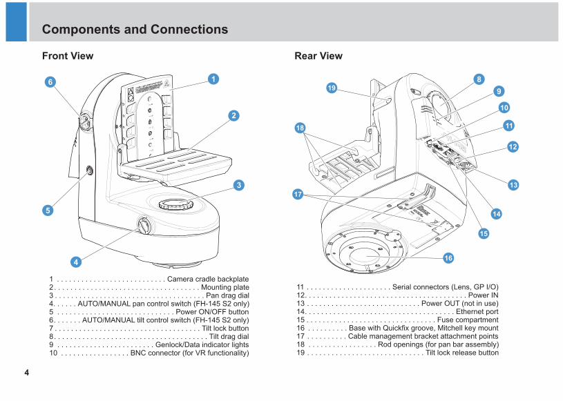
Front View Rear View
11 . . . . . . . . . . . . . . . . . . . . . Serial connectors (Lens, GP I/O)12. . . . . . . . . . . . . . . . . . . . . . . . . . . . . . . . . . . . . . . . Power IN13 . . . . . . . . . . . . . . . . . . . . . . . . . . . . Power OUT (not in use)14. . . . . . . . . . . . . . . . . . . . . . . . . . . . . . . . . . . . . Ethernet port15 . . . . . . . . . . . . . . . . . . . . . . . . . . . . . . . . Fuse compartment
18 . . . . . . . . . . . . . . . . . Rod openings (for pan bar assembly)19 . . . . . . . . . . . . . . . . . . . . . . . . . . . . . Tilt lock release button
16 . . . . . . . . . . Base with Quickfix groove, Mitchell key mount17 . . . . . . . . . . Cable management bracket attachment points
1
7 . . . . . . . . . . . . . . . . . . . . . . . . . . . . . . . . . . . . Tilt lock button8. . . . . . . . . . . . . . . . . . . . . . . . . . . . . . . . . . . . . . Tilt drag dial9 . . . . . . . . . . . . . . . . . . . . . . . . Genlock/Data indicator lights10 . . . . . . . . . . . . . . . . . BNC connector (for VR functionality)
. . . . . . . . . . . . . . . . . . . . . . . . . . . Camera cradle backplate2. . . . . . . . . . . . . . . . . . . . . . . . . . . . . . . . . . . . Mounting plate3 . . . . . . . . . . . . . . . . . . . . . . . . . . . . . . . . . . . . . Pan drag dial4. . . . . . AUTO/MANUAL pan control switch (FH-145 S2 only)5 . . . . . . . . . . . . . . . . . . . . . . . . . . . . . Power ON/OFF button6. . . . . . . AUTO/MANUAL tilt control switch (FH-145 S2 only)
17
13
14
12
19
15
18
10
11
16
5
FHR-35 Pan and Tilt HeadRoboticFHR-35 Robotic Pan and Tilt HeadInstallation
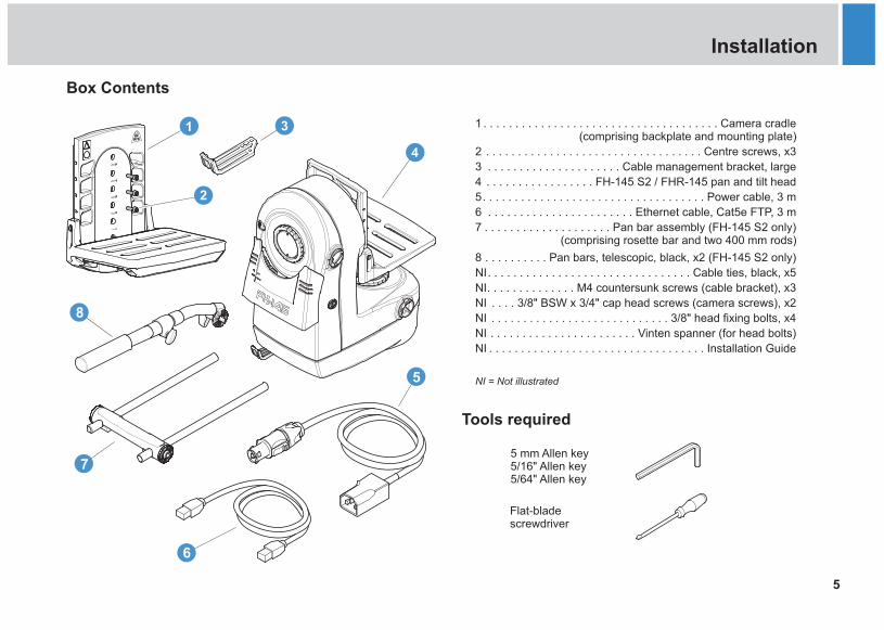
1 . . . . . . . . . . . . . . . . . . . . . . . . . . . . . . . . . . . . . Camera cradle(comprising backplate and mounting plate)
2 . . . . . . . . . . . . . . . . . . . . . . . . . . . . . . . . . . Centre screws, x3
3 . . . . . . . . . . . . . . . . . . . . . Cable management bracket, large
4 . . . . . . . . . . . . . . . . .
5. . . . . . . . . . . . . . . . . . . . . . . . . . . . . . . . . . .
NI = Not illustrated
FH-145 S2 / FHR-145 pan and tilt head
Power cable, 3 m
6 . . . . . . . . . . . . . . . . . . . . . . . Ethernet cable, Cat5e FTP, 3 m
7 . . . . . . . . . . . . . . . . . . . . Pan bar assembly (FH-145 S2 only)(comprising rosette bar and two 400 mm rods)
8 . . . . . . . . . . Pan bars, telescopic, black, x2 (FH-145 S2 only)
NI. . . . . . . . . . . . . . . . . . . . . . . . . . . . . . . . Cable ties, black, x5
NI. . . . . . . . . . . . . . M4 countersunk screws (cable bracket), x3
NI . . . . 3/8" BSW x 3/4" cap head screws (camera screws), x2
NI . . . . . . . . . . . . . . . . . . . . . . . . . . . . 3/8" head fixing bolts, x4
NI . . . . . . . . . . . . . . . . . . . . . . . Vinten spanner (for head bolts)
NI . . . . . . . . . . . . . . . . . . . . . . . . . . . . . . . . . . Installation Guide
Tools required
5 mm Allen key5/16" Allen key5/64" Allen key
5
6
8
7
4
Flat-blade screwdriver
Box Contents
6
FHR-35 Robotic Pan and Tilt HeadInstallation
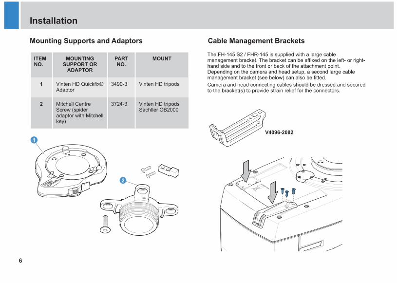
Mounting Supports and Adaptors Cable Management Brackets
ITEMNO.
MOUNTING SUPPORT OR
ADAPTOR
PART NO.
MOUNT
1 Vinten HD Quickfix® Adaptor
3490-3 Vinten HD tripods
2 Mitchell Centre Screw (spider adaptor with Mitchell key)
3724-3 Vinten HD tripodsSachtler OB2000
The FH-145 S2 / FHR-145 is supplied with a large cable management bracket an be affixed on the left- or right-hand side and to the front or back of the attachment point. Depending on the camera and head setup, a second large cable management bracket (see below) can also be fitted.
Camera and head connecting cables should be dressed and secured to the bracket(s) to provide strain relief for the connectors.
. The bracket c
V4096-2082
2
1
7
FHR-35 Pan and Tilt HeadRoboticFHR-35 Robotic Pan and Tilt HeadInstallation
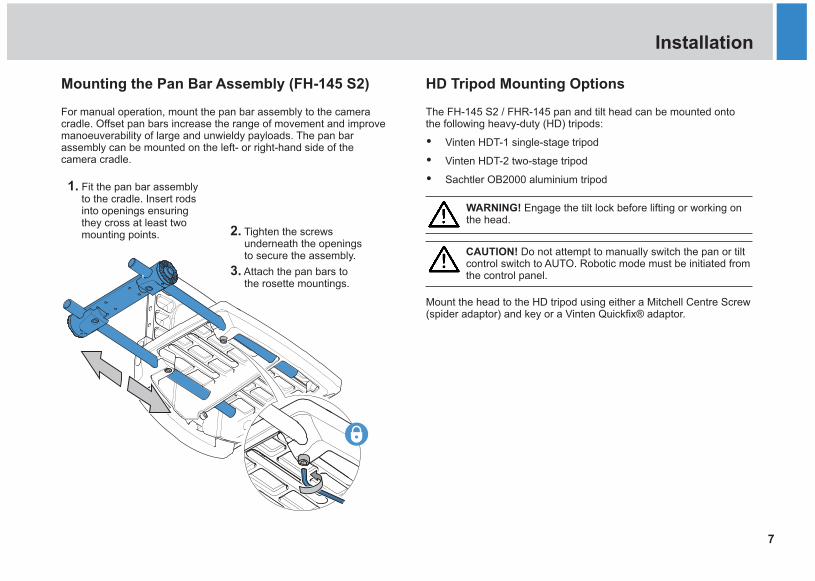
Mounting the Pan Bar Assembly (FH-145 S2) HD Tripod Mounting Options
The FH-145 S2 / FHR-145 pan and tilt head can be mounted onto the following heavy-duty (HD) tripods:
Ÿ Vinten HDT-1 single-stage tripod
Ÿ Vinten HDT-2 two-stage tripod
Ÿ Sachtler OB2000 aluminium tripod
Mount the head to the HD tripod using either a Mitchell Centre Screw (spider adaptor) and key or a Vinten Quickfix® adaptor.
WARNING! Engage the tilt lock before lifting or working on the head.
For manual operation, mount the pan bar assembly to the camera cradle. Offset pan bars increase the range of movement and improve manoeuverability of large and unwieldy payloads. The pan bar assembly can be mounted on the left- or right-hand side of the camera cradle.
1. Fit the pan bar assembly to the cradle. Insert rods into openings ensuring they cross at least two mounting points. 2. Tighten the screws
underneath the openings to secure the assembly.
3. Attach the pan bars to the rosette mountings.
CAUTION! Do not attempt to manually switch the pan or tilt control switch to AUTO. Robotic mode must be initiated from the control panel.
8
FHR-35 Robotic Pan and Tilt HeadInstallation
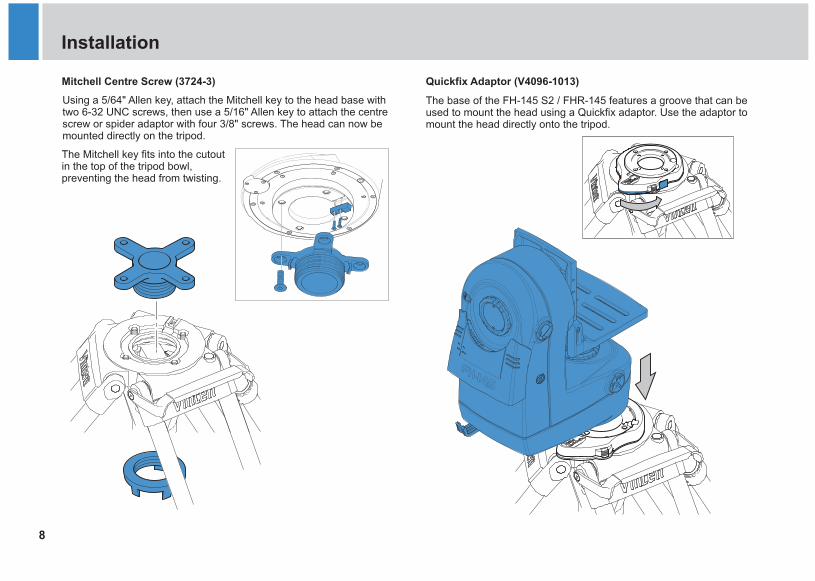
Using a 5/64" Allen key, attach the Mitchell key to the head base with two 6-32 UNC screws, then use a 5/16" Allen key to attach the centre screw or spider adaptor with four 3/8" screws. The head can now be mounted directly on the tripod.
Mitchell Centre Screw (3724-3)
The base of the FH-145 S2 / FHR-145 features a groove that can be used to mount the head using a Quickfix adaptor. Use the adaptor to mount the head directly onto the tripod.
Quickfix Adaptor (V4096-1013)
The Mitchell key fits into the cutout in the top of the tripod bowl, preventing the head from twisting.
9
FHR-35 Pan and Tilt HeadRoboticFHR-35 Robotic Pan and Tilt HeadInstallation
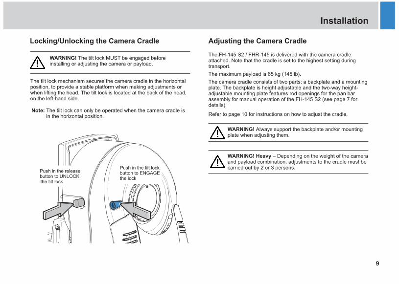
Locking/Unlocking the Camera Cradle Adjusting the Camera Cradle
The FH-145 S2 / FHR-145
The maximum payload is 65 kg (145 lb).
mounting plate
.
is delivered with the camera cradle attached. Note that the cradle is set to the highest setting during transport.
The camera cradle consists of two parts: a backplate and a mounting plate. The backplate is height adjustable and the two-way height-adjustable features rod openings for the pan bar assembly for manual operation of the FH-145 S2 (see page 7 for details)
Refer to page 10 for instructions on how to adjust the cradle.
The tilt lock the camera cradle in the horizontal position, to provide a stable platform when making adjustments or when lifting the head. The tilt lock is located at the back of the head, on the left-hand side.
mechanism secures
WARNING! The tilt lock MUST be engaged before installing or adjusting the camera or payload.
Note: The tilt lock can only be operated when the camera cradle is in the horizontal position.
WARNING! Heavy – Depending on the weight of the camera and payload combination, adjustments to the cradle must be carried out by 2 or 3 persons.
WARNING! Always support the backplate and/or mounting plate when adjusting them.
10
FHR-35 Robotic Pan and Tilt HeadInstallation
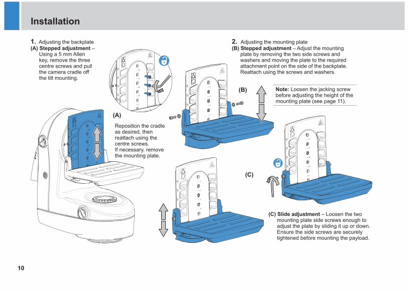
2. Adjusting the mounting plate(B) Stepped adjustment – Adjust the mounting
plate by removing the two side screws and washers and moving the plate to the required attachment point on the side of the backplate. Reattach using the screws and washers.
(C) Slide adjustment – Loosen the two mounting plate side screws enough to adjust the plate by sliding it up or down. Ensure the side screws are securely tightened before mounting the payload.
(A)
(B)
(C)
Note: Loosen the jacking screw before adjusting the height of the mounting plate (see page 11).
1. Adjusting the backplate(A) Stepped adjustment –
Using a 5 mm Allen key, remove the three centre screws and pull the camera cradle off the tilt mounting.
Reposition the cradle as desired, then reattach using the centre screws.If necessary, remove the mounting plate.
11
FHR-35 Pan and Tilt HeadRoboticFHR-35 Robotic Pan and Tilt HeadInstallation
Adjusting the Horizon Level Mounting the Camera
1.
2.
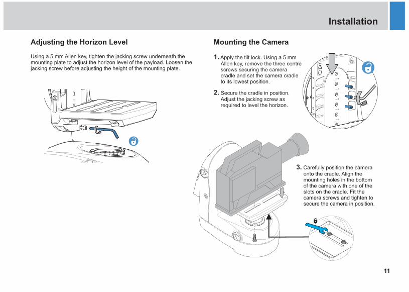
Apply the tilt lock. Using a 5 mm Allen key, remove the three centre screws securing the camera cradle and set the camera cradle to its lowest position.
Secure the cradle in position. Adjust the jacking screw as required to level the horizon.
3. Carefully position the camera onto the cradle. Align the mounting holes in the bottom of the camera with one of the slots on the cradle. Fit the camera screws and tighten to secure the camera in position.
Using a 5 mm Allen key, tighten the jacking screw underneath the mounting plate to adjust the horizon level of the payload. Loosen the jacking screw before adjusting the height of the mounting plate.
12
FHR-35 Robotic Pan and Tilt HeadInstallation
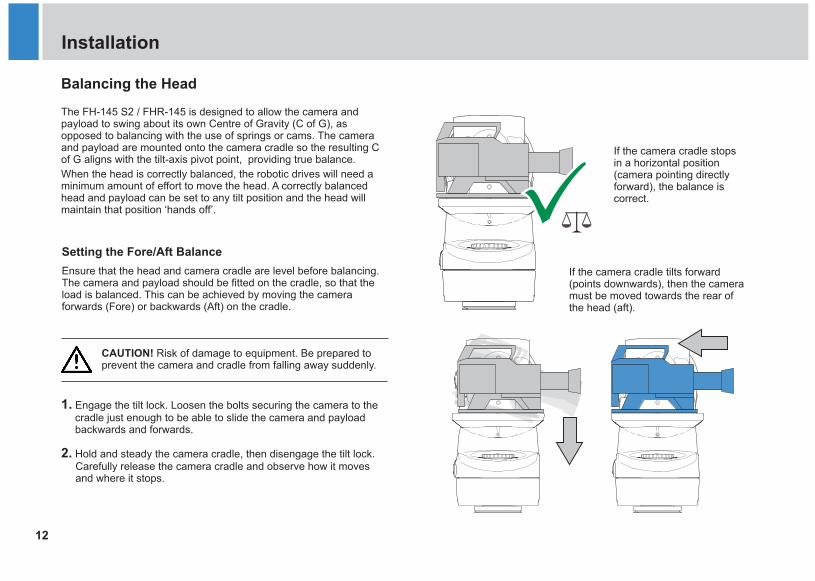
Balancing the Head
If the camera cradle stops in a horizontal position (camera pointing directly forward), the balance is correct.
Setting the Fore/Aft Balance
Ensure that the head and camera cradle are level before balancing. The camera and payload should be fitted on the cradle, so that the load is balanced. This can be achieved by moving the camera forwards (Fore) or backwards (Aft) on the cradle.
1. Engage the tilt lock. Loosen the bolts securing the camera to the cradle just enough to be able to slide the camera and payload backwards and forwards.
2. Hold and steady the camera cradle, then disengage the tilt lock. Carefully release the camera cradle and observe how it moves and where it stops.
If the camera cradle tilts forward (points downwards), then the camera must be moved towards the rear of the head (aft).
CAUTION! Risk of damage to equipment. Be prepared to prevent the camera and cradle from falling away suddenly.
The FH-145 S2 / FHR-145 is designed to allow the camera and payload to swing about its own Centre of Gravity (C of G), as opposed to balancing with the use of springs or cams. The camera and payload are mounted onto the camera cradle so the resulting C of G aligns with the tilt-axis pivot point, providing true balance.
When the head is correctly balanced, the robotic drives will need a minimum amount of effort to move the head. A correctly balanced head and payload can be set to any tilt position and the head will maintain that position ‘hands off’.
13
FHR-35 Pan and Tilt HeadRoboticFHR-35 Robotic Pan and Tilt HeadInstallation
4. Tighten the bolts securing the camera to the cradle and recheck the horizontal balance. Readjust if necessary.
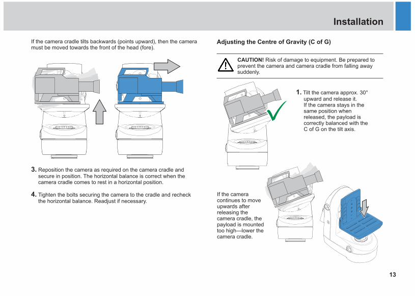
Adjusting the Centre of Gravity (C of G)
3. Reposition the camera as required on the camera cradle and secure in position. The horizontal balance is correct when the camera cradle comes to rest in a horizontal position.
If the camera cradle tilts backwards (points upward), then the camera must be moved towards the front of the head (fore).
1. Tilt the camera approx. 30° upward and release it.If the camera stays in the same position when released, the payload is correctly balanced with the C of G on the tilt axis.
CAUTION! Risk of damage to equipment. Be prepared to prevent the camera and camera cradle from falling away suddenly.
If the camera continues to move upwards after releasing the camera cradle, the payload is mounted too high—lower the camera cradle.
14
FHR-35 Robotic Pan and Tilt HeadInstallation
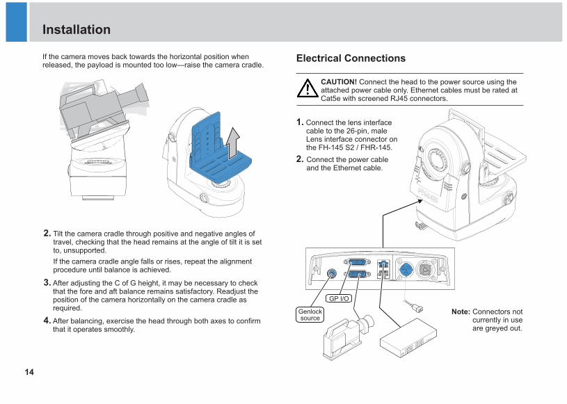
Electrical ConnectionsIf the camera moves back towards the horizontal position when released, the payload is mounted too low—raise the camera cradle.
2. Tilt the camera cradle through positive and negative angles of travel, checking that the head remains at the angle of tilt it is set to, unsupported.
If the camera cradle angle falls or rises, repeat the alignment procedure until balance is achieved.
3. After adjusting the C of G height, it may be necessary to check that the fore and aft balance remains satisfactory. Readjust the position of the camera horizontally on the camera cradle as required.
4. After balancing, exercise the head through both axes to confirm that it operates smoothly.
1. Connect the lens interface cable to the 26-pin, male Lens interface connector on the FH-145 S2 / FHR-145.
2. Connect the power cable and the Ethernet cable.
CAUTION! Connect the head to the power source using the attached power cable only. Ethernet cables must be rated at Cat5e with screened RJ45 connectors.
Note: Connectors not currently in use are greyed out.
GP I/O
Genlock source
15
FHR-35 Pan and Tilt HeadRoboticFHR-35 Robotic Pan and Tilt HeadInstallation
Cable Management Powering Up
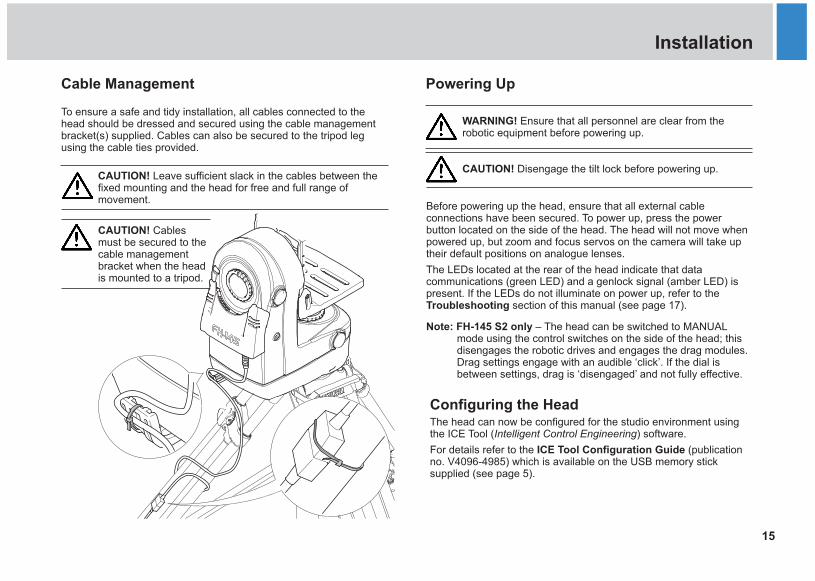
To ensure a safe and tidy installation, all cables connected to the head should be dressed and secured using the cable management bracket(s) supplied. Cables can also be secured to the tripod leg using the cable ties provided.
CAUTION! Leave sufficient slack in the cables between the fixed mounting and the head for free and full range of movement.
WARNING! Ensure that all personnel are clear from the robotic equipment before powering up.
CAUTION! Disengage the tilt lock before powering up.
Before powering up the head, ensure that all external cable connections have been secured. To power up, press the power button located on the side of the head. The head will not move when powered up, but zoom and focus servos on the camera will take up their default positions on analogue lenses.
The LEDs located at the rear of the head indicate that data communications (green LED) and a genlock signal (amber LED) is present. If the LEDs do not illuminate on power up, refer to the Troubleshooting section of this manual (see page 17).
Note: FH-145 S2 only – The head can be switched to MANUAL mode using the control switches on the side of the head; this disengages the robotic drives and engages the drag modules. Drag settings engage with an audible ‘click’. If the dial is between settings, drag is ‘disengaged’ and not fully effective.
The head can now be configured for the studio environment using the ICE Tool (Intelligent Control Engineering) software.
For details refer to the ICE Tool Configuration Guide (publication no. V4096-4985) which is available on the USB memory stick supplied (see page 5).
Configuring the Head
CAUTION! Cables must be secured to the cable management bracket when the head is mounted to a tripod.
16
FHR-35 Robotic Pan and Tilt HeadOperation
Manual Mode (FH-145 S2 only)
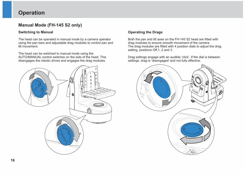
The head can be operated in manual mode by a camera operator using the pan bars and adjustable drag modules to control pan and tilt movement.
The head can be switched to manual mode using the AUTO/MANUAL control switches on the side of the head. This disengages the robotic drives and engages the drag modules.
Switching to Manual Operating the Drags
Both the pan and tilt axes on the FH-145 S2 head are fitted with drag modules to ensure smooth movement of the camera.The drag modules are fitted with 4 position dials to adjust the drag setting, positions .
Drag settings engage with an audible ‘click’. If the dial is between settings, drag is ‘disengaged’ and not fully effective.
Off,1, 2 and 3
17
FHR-35 Pan and Tilt HeadRoboticFHR-35 Robotic Pan and Tilt HeadMaintenance
Regular Checks
Routine Use
During use, check the following regularly:
Ÿ Once a month check the balance of the camera and payload and adjust if necessary.
Ÿ Check the integrity of bolts and fixings securing the head to the support.
Ÿ Check the bolts and fixings securing the payload.
No further routine maintenance is required.
Cleaning
We encourage regular cleaning of the product. During normal use the only cleaning required should be a regular wipe over with a lint-free dry cloth. External electrical connection ports should only be cleaned with a vacuum cleaner.
Cover the head when not in use. Dirt accumulated during storage or periods of non-use may be removed with a vacuum cleaner.
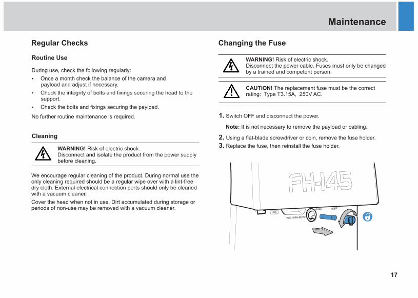
WARNING! Risk of electric shock. Disconnect the power cable. Fuses must only be changed by a trained and competent person.
WARNING! Risk of electric shock. Disconnect and isolate the product from the power supply before cleaning.
1.
2.3.
Switch OFF and disconnect the power.
Note: It is not necessary to remove the payload or cabling.
Using a flat-blade screwdriver or coin, remove the fuse holder.
Replace the fuse, then reinstall the fuse holder.
CAUTION! The replacement fuse must be the correct rating: Type T3.15A, 250V AC.
Changing the Fuse
18
FHR-35 Robotic Pan and Tilt HeadTroubleshooting
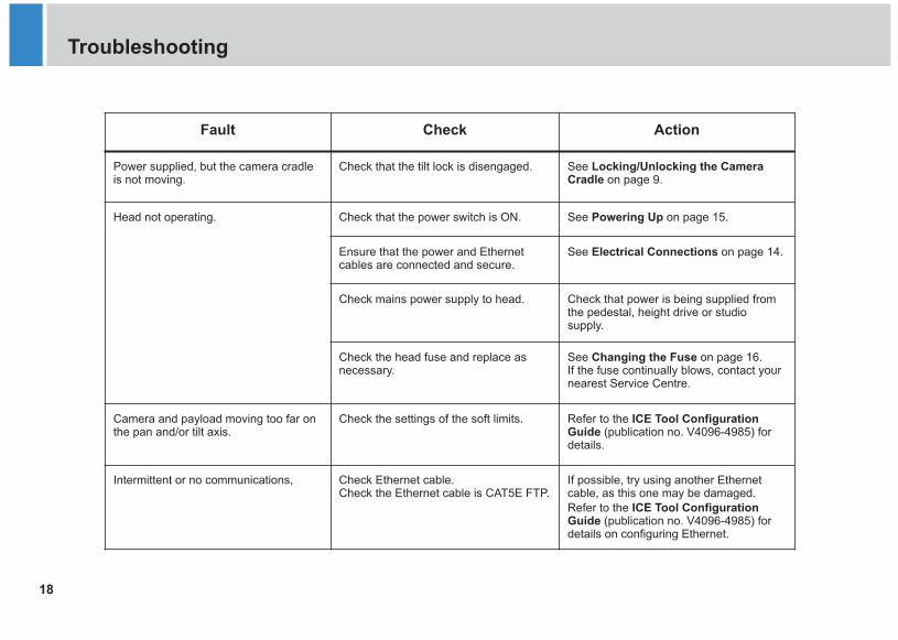
Fault Check Action
Power supplied, but the camera cradle is not moving.
Check that the tilt lock is disengaged. See Locking/Unlocking the Camera Cradle on page 9.
Head not operating. Check that the power switch is ON. See Powering Up on page 15.
Ensure that the power and Ethernet cables are connected and secure.
See Electrical Connections on page 14.
Check mains power supply to head. Check that power is being supplied from the pedestal, height drive or studio supply.
Check the head fuse and replace as necessary.
See Changing the Fuse on page 16. If the fuse continually blows, contact your nearest Service Centre.
Camera and payload moving too far on the pan and/or tilt axis.
Check the settings of the soft limits. Refer to the ICE Tool Configuration Guide (publication no. V4096-4985) for details.
Intermittent or no communications, Check Ethernet cable.Check the Ethernet cable is CAT5E FTP.
If possible, try using another Ethernet cable, as this one may be damaged. Refer to the ICE Tool Configuration Guide (publication no. V4096-4985) for details on configuring Ethernet.
19
FHR-35 Pan and Tilt HeadRoboticFHR-35 Robotic Pan and Tilt HeadGeneral Notices
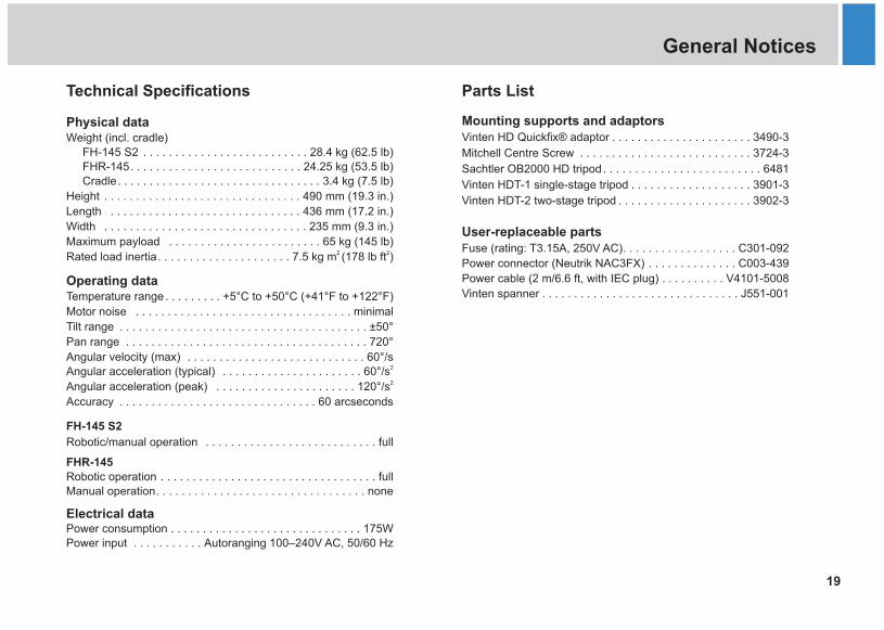
Technical Specifications Parts List
Mounting supports and adaptorsVinten HD Quickfix adaptor . . . . . . . . . . . . . . . . . . . . . . 3490-3
Mitchell Centre Screw . . . . . . . . . . . . . . . . . . . . . . . . . . . 3724-3
. . . . . . . . . . . . . . . . . . .
. . . . . . . . . . . . . . . . . . . . .
®
User-replaceable partsFuse (rating: T3.15A, 250V AC). . . . . . . . . . . . . . . . . . C301-092
Sachtler OB2000 HD tripod . . . . . . . . . . . . . . . . . . . . . . . . . 6481
Vinten HDT-1 single-stage tripod 3901-3
Vinten HDT-2 two-stage tripod 3902-3
Power connector (Neutrik NAC3FX) . . . . . . . . . . . . . . C003-439
Power cable (2 m/6.6 ft, with IEC plug) . . . . . . . . . . V4101-5008
Vinten spanner . . . . . . . . . . . . . . . . . . . . . . . . . . . . . . . J551-001
Ph
payload . . . . . . . . . . . . . . . . . . . . . . . . 65 kg (145 lb)2 Rated load inertia. . . . . . . . . . . . . . . . . . . . . 7.5 kg m (178 lb ft )
Operating dataTemperature range . . . . . . . . . +5°C to +50°C (+41°F to +122°F)
Motor noise . . . . . . . . . . . . . . . . . . . . . . . . . . . . . . . . . . minimal
Tilt range . . . . . . . . . . . . . . . . . . . . . . . . . . . . . . . . . . . . . . . ±50°
Pan range . . . . . . . . . . . . . . . . . . . . . . . . . . . . . . . . . . . . . . 720°
Angular velocity (max) . . . . . . . . . . . . . . . . . . . . . . . . . . . . 60°/s2Angular acceleration (typical) . . . . . . . . . . . . . . . . . . . . . . 60°/s2Angular acceleration (peak) . . . . . . . . . . . . . . . . . . . . . . 120°/s
Accuracy . . . . . . . . . . . . . . . . . . . . . . . . . . . . . . . 60 arcseconds
FH-145 S2
Robotic/manual operation . . . . . . . . . . . . . . . . . . . . . . . . . . . full
FHR-145Robotic operation . . . . . . . . . . . . . . . . . . . . . . . . . . . . . . . . . . fullManual operation. . . . . . . . . . . . . . . . . . . . . . . . . . . . . . . . . none
Electrical dataPower consumption . . . . . . . . . . . . . . . . . . . . . . . . . . . . . . 175WPower input . . . . . . . . . . . Autoranging 100–240V AC, 50/60 Hz
ysical dataWeight (incl. cradle)
FH-145 S2 . . . . . . . . . . . . . . . . . . . . . . . . . . 28.4 kg (62.5 lb)FHR-145. . . . . . . . . . . . . . . . . . . . . . . . . . . 24.25 kg (53.5 lb)Cradle. . . . . . . . . . . . . . . . . . . . . . . . . . . . . . . . 3.4 kg (7.5 lb)
Height . . . . . . . . . . . . . . . . . . . . . . . . . . . . . . . 490 mm (19.3 in.)
Length . . . . . . . . . . . . . . . . . . . . . . . . . . . . . . 436 mm (17.2 in.)
Width . . . . . . . . . . . . . . . . . . . . . . . . . . . . . . . . 235 mm (9.3 in.)
Maximum 2

20
FHR-35 Robotic Pan and Tilt HeadGeneral Notices
General Purpose Connector
The GP I/O connector (see page 14) can be configured and enabled in ICE Tool. It can be used to connect a Camera Control Unit (CCU) or for powering auxiliary devices. The pinouts for the connector are given in the table below.
26-pin, female
CAUTION! Total power drawn from the 12V pins of this connector must NOT exceed 30W.
Pin No. Description Pin No. Description
1 Not connected 14 Not connected
2 Aux GND 15 CCU TXD422
3 Aux +12V 16 CCU TXD232
4 Aux +12V 17 Not connected
5 Not connected 18 GP I/O 1
6 CCU RXD422 19 GND
7 CCU RXD232 20 Aux GND
8 GP I/O 3 21 Aux +12V
9 GP I/O 0 22 Not connected
10 GND 23 CCU TXD422
11 Aux GND 24 CCU RXD422
12 Aux GND 25 Not connected
13 Aux +12V 26 GP I/O 2
Declaration of Conformity Limited declares that this product has
been manufactured in accordance with BS EN ISO 9001:2008 and is in compliance with the essential requirements and other relevant provisions of the
Machinery Directive 2006/42/EC.
A copy of the Declaration of Conformity is available upon request.
Vitec Videocom
Waste of Electrical and Electronic Equipment (WEEE) Directive (2002/96/EC)
This symbol marked on the product or its packing indicates that this product must not be disposed of with general household waste. In some countries or European Community regions, separate collection systems have been set up to handle the recycling of electrical and electronic waste products.
By ensuring this product is disposed of correctly you will help prevent potentially negative consequences for the environment and human health. The recycling of materials helps conserve natural resources.
In countries outside the EU:
Dispose of this product at a collection point for the recycling of electrical and electronic equipment according to your local government regulations.
Visit our website for information on how to safely dispose of this product and its packaging.
Compliance
21
FHR-35 Pan and Tilt HeadRoboticFHR-35 Robotic Pan and Tilt HeadGeneral Notices
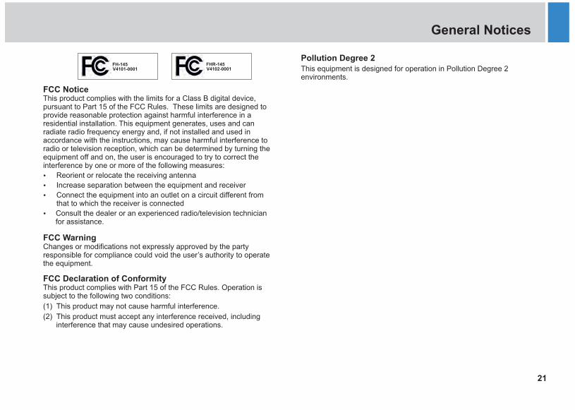
Pollution Degree 2This equipment is designed for operation in Pollution Degree 2 environments.
FHR-145V4102-0001
FCC NoticeThis product complies with the limits for a Class B digital device, pursuant to Part 15 of the FCC Rules. These limits are designed to provide reasonable protection against harmful interference in a residential installation. This equipment generates, uses and can radiate radio frequency energy and, if not installed and used in accordance with the instructions, may cause harmful interference to radio or television reception, which can be determined by turning the equipment off and on, the user is encouraged to try to correct the interference by one or more of the following measures:
Ÿ Reorient or relocate the receiving antenna
Ÿ Increase separation between the equipment and receiver
Ÿ Connect the equipment into an outlet on a circuit different from that to which the receiver is connected
Ÿ Consult the dealer or an experienced radio/television technician for assistance.
FCC WarningChanges or modifications not expressly approved by the party responsible for compliance could void the user’s authority to operate the equipment.
FCC Declaration of ConformityThis product complies with Part 15 of the FCC Rules. Operation is subject to the following two conditions:
(1) This product may not cause harmful interference.
(2) This product must accept any interference received, including interference that may cause undesired operations.
FH-145V4101-0001

Publication No. V4101-4980/2
VA V
intenitec Group brand
™
www.vinten.com