Palsun Technical Guide - Bay Plastics Ltd
44
PALSUN® Flat Polycarbonate Sheet www.palram.com Technical Guide
Transcript of Palsun Technical Guide - Bay Plastics Ltd

PALSUN®Flat Polycarbonate Sheet
ww
w.p
alram.co
m
Technical Guide

PALSUN®
1
Content
Chapter Page
PALSUN® Product Range 2
Standard Dimensions 3
Quantity per Pallet 3
Physical Properties 4
Impact Strength 5
Optical Characteristics 6
Thermo-Optical Properties 6
Solar Transmission Properties 7
Weather Resistance 9
Acoustic Properties 9
Flammability 10
Chemical Resistance 11
Adhesives & Sealants 15
Selection of Approprriate PALSUN® Sheet 15
General Recommendations for Working with PALSUN® 16
Fabrication - General Guidelines 17
Fabrication - Sawing & Cutting 17
Fabrication - Shearing & Punching 21
Fabrication - Other Cutting Options 23
Drilling 25
Finishing 26
Forming - Cold Forming 28
Forming - Thermoforming 29
Forming - Annealing 26
Forming - Tips on PALSUN® Thermoforming 36
Fault & Remedies in Thermoforming Practive 37
Joining 38

Technical Guide
2
PALSUN® Product Range
Some of the products' features below can be combined. Please contact your Palram dealer for further information.
Product Description Features & Applications
PALTUF®UV stabilized, general purpose, flat solid polycarbonate sheet.
Recommended for indoor use only.
PALSUN®Flat solid polycarbonate sheet with UV protective layer on one side.
Suitable for both exterior and indoor applications.Optional surface textures: Embossed (E-102) Prismatic hair-cell Matte - Anti-glare effect
PALSUN® UV2Flat solid polycarbonate sheet with UV protective layer on both sides.
Recommended for applications that involve UV exposure on both sides (e.g. exterior light boxes)
PALSUN® FRSheet with higher fire resistance rating (e.g. UL 94 V-0).
Recommended for applications in populated areas.
PALSUN® Solar Control
Sheet with integrated heat-blocking layer. This metallic reflective layer that transmits less Infra-Red radiation and reduces heat buildup.
Available with 20, 35, or 50% light transmission
PALSUN® Smart
Sheet with a smart integrated heat-blocking tint, which transmits more visible light and less heat, while also offering high transparency.
Can be tailored to achieve different light and heat transmissions.
PALGARD™Sheet with abrasion resistant layer on one or both layers.
Recommended for applications in high traffic areas, harsh chemical environments or those requiring anti-vandal properties.
PALSUN® LB Sheet with a high light diffuision.Ideal for light boxes and other illuminated sig-nage applications.
Notes:1. All the above sheets are supplied with a protective polyethylene (PE) film on both sides (one side upon request), with the UV protected side clearly marked. This film should be removed immediately after installation.2. For transportation, handling and storage instructions and recommendations, please refer to “General Recommendation for Working with PALSUN ”. (page 16)3. PALSUN sheets are backed by a 10 years limited warranty, available upon request.4. Most PALSUN sheets are available in the transparent, translucent or opaque form, in a variety of colors, either standard or custom ordered.

PALSUN®
3
Standard Dimensions*
Thickness Width x Length Weight Surface Finish
mm Inch mm inch g/m2 psfSmooth
both sidesHair Cell one side
Matte one side
Embossed both sides
Prismatic one side
1 0.04 1220 x 2440
1250 x 2440
48 x 96
50 x 96
1,190 0.24 ✔ ✔ ✔
1.5 0.06 1,785 0.36 ✔ ✔ ✔ ✔ ✔
2 0.08
1220 x 2440
1250 x 2440
2050 x 3050
48 x 96
50 x 96
80 x 120
2,380 0.49 ✔ ✔ ✔ ✔ ✔
2.5 0.10 2,975 0.60 ✔ ✔ ✔ ✔ ✔
3 0.12 3,570 0.74 ✔ ✔ ✔ ✔ ✔
4 0.16 4,760 0.97 ✔ ✔ ✔ ✔ ✔
5 0.20 5,950 1.22 ✔ ✔ ✔ ✔ ✔
6 0.24 7,140 1.44 ✔ ✔ ✔ ✔ ✔
8 0.32 9,520 1.95 ✔ ✔ ✔ ✔
9 0.36 10,710 2.19 ✔ ✔ ✔
10 0.40 11,900 2.73 ✔ ✔ ✔
12 0.47 14,280 3.28 ✔ ✔ ✔
*Other options are available upon a special order, subject to minimum quantity.
Standard Colors*
Transparent Translucent Opqaue
ClearSolar GrayBronzeRedBlueGreenSmart Green
YellowRedMint-GreenWhite Opal (11-50%LT)Diffuser (11-50%LT)Solar IceSolar ControlSolar Olympic
Dark GreenBrick RedBlackDark BlueCream (RAL 9001)Light Gray (RAL 7035)Dark GrayBrownOff-White
*Other colors are available upon a special order, subject to minimum quantity.
Quantity per Pallet
Thickness mm
1250x2050 Pallet(50” x 80”)
1220x2440 Pallet(48” x 96”)
2050x3050 Pallet(50” x 120”)
1 300 300 -
1.5 200 200 -
2 150 150 70
3 100 100 50
4 75 75 35
4.5 65 65 30
5 60 60 30
6 50 50 25
8 40 40 20
10 30 30 15
12 25 25 12

Technical Guide
4
Physical Properties
The following table displays physical properties of 3mm (0.12 inch) PALSUN and PALTUF sheets.
Property Method**Conditions
(U.S. Customary)*Units - SI
(U.S. Customary)*Value
(U.S. Customary)*
Physical
Density D-792 g/cm3 (lb/ft3) 1.2 (75)
Water Absorption D-570 24 hr. @ 23°C % 0.15
Mechanical
Tensile strength at yield D-638 10 mm/min (0.4 in./min) MPa (psi) 62.5 (9,100)
Tensile strength at break D-638 10 mm/min (0.4 in./min) MPa (psi) 65 (9,500)
Elongation at yield D-638 10 mm/min (0.4 in./min) % 6
Elongation at break D-638 10 mm/min (0.4 in./min) % >80
Tensile Modulus of Elasticity D-638 1 mm/min (0.4 in./min) MPa (psi) 2,300 (290,000)
Flexural Modulus D-790 1.3 mm/min (0.052 in./min) MPa (psi) 2,350 (343,000)
Flexural Strength at Yield D-790 1.3 mm/min (0.052 in./min) MPa (psi) 93 (13,600)
Notched Impact Strength Izod D-256 23°C (73°F) J/m (ft·lbf/in.) 800 (15)
Notched Impact Strength Charpy D-256 23°C (73°F) J/m (ft·lbf/in.) 800 (15)
Impact Falling Weight ISO-6603/1b J (ft·lbf ) 158 (117)
Rockwell Hardness D-785 R scale / M scale 125 / 75
Thermal
Long Term Service Temperature °C (°F) -50 to +100 (-175 to +212)
Short Term Service Temperature °C (°F) -50 to +120 (-175 to +250)
Heat Deflection Temperature D-648 Load: 1.82 MPa (264 psi) °C (°F) 135 (275)
Vicat Softening Temperature D-1525 Load: 1 kg (2.2 lb) °C (°F) 150 (300)
Coefficient of Linear Thermal Expansion D-696 mm/m °C (Mil/in. °F) 0.065 (0.036)
Thermal Conductivity C-177 W/m K (Btu·in/hr·ft2·°F) 0.21 (1.46)
Specific Heat Capacity C-351 kJ/kg·°K (Btu/lb·°F) 1.26 (0.31)
Optical
Haze D-1003 Clear Sheet % <0.5
Light Transmission D-1003 Clear Sheet % 89
Refractive Index D-542 Clear Sheet 1.586
Yellowness Index D-1925 Clear Sheet <1
Electrical
Dielectric ConstantD-150 50 Hz 3.0
D-150 1 MHz 2.9
Dissipation FactorD-150 1 KHz 0.001
D-150 1 MHz 0.01
Dielectric Strength Short Time D-149 500 V/s kV/mm (V/mil) >30 (>770)
Surface Resistivity D-257 Keithley Ohm 1016
Volume Resistance D-257 Keithley Ohm-cm 1017
* Conditions, units and values in U.S. Customary units are presented in the table within parentheses.** ASTM except where noted otherwise.

PALSUN®
5
Impact Strength
PALSUN sheets are manufactured from polycarbonate, the most versatile, toughest transparent thermoplastic. PALSUN has 200 times the impact strength of glass, offering excellent protection against riots and public disturbances, breaking & entering or acts of vandalism.PALSUN can endure attacks by rocks, clubs, hammers and thrown objects, and still to retain its original shape, maintain its integrity with minimal indentations to its surface.The amount of damage depends on the object mass and energy, and sheet’s thickness. PALSUN sheets will retain these energy-absorbing properties over a wide temperature range (50° to + 100° C).
Typical impact failure energy of PALSUN sheets*
Thickness mm
Energy at Failure E50 (Jouls)
Type of Failure
2 110 100% ductile
3 150 100% ductile
4 190 100% ductile
5 290 100% ductile
6 400 100% ductile
8 N.B.** N.B.**
10 N.B.** N.B.**
12 N.B.** N.B.**
* According to ISO 6603/1 1985(E): Determination of multi-axial impact behavior of rigid plastics.
Legend
1. Leveled floor2. Stablized base3. Supporting guidrails4. Lifting mechanism5. Disengagement mechanism6. Guidance bar7. Changeable weight8. 20 mm diameter head falling dart9. Tested specimen10. Caliberation bar11. Changeable drop height
Falling Dart Method
A uniform energy increment is employed during testing. Energy is decreased or increased by uniform increment after testing each specimen, depending upon the result (failed / not failed) observed for the former tested sample. A 20 mm diameter dart, weighing 8 kg, with a rounded tip, is raised to a certain height and released to fall on a suitably sized sample.Principles: Impact strength is determined by the known weight and height. Adjustment is done by altering height while using a constant mass.E50: 50% of Impact Failure Energy. The energy that will cause 50% of the tested samples to fail.N.B.**: No Break. The energy required to break the sample is greater than what the test instrument can deliver.
Figure 1: Falling Dart Impact Testing Device (Schematic)

Technical Guide
6
Light Transmission Versus ThicknessLight transmission decreases slightly with increased thickness (see attached graph).
Optical Characteristics
Ultraviolet (UV) Radiation Blocking- PALSUN sheets completely block out potentially harmful UV radiation and a significant portion of infrared (IR) radiation. Over the visible light range, a typical 3 mm (1/8 in.) thick clear PALSUN sheet transmits about 89% (average) of incident light, as seen in the attached graph.
Thermo-Optical Properties
Thermal conductivity is an important factor to consider when choosing a glazing material, due to its influence on thermal efficiency and energy lose in winter (heating) or summer (air-conditioning). PALSUN sheets insulate better than glass, contributing to substantial energy conservation for single glazing.
PALSUN vs. Glass K- Values in Single Glazing (W/m2 K) Sheet thickness
Thickness mm
PALSUN® K Value Glass K Value
3 5.49 5.87
5 5.21 5.80
6 5.09 5.77
9.5 4.69 5.68
12 4.35 5.58
% L
ight
Tra
nsm
issi
on
Thickness (mm)
Figure 3: Light Transmission Versus Wavelength100
90
80
70
60
50
40
30
20
10
0
PALSUN® & PALTUF®
0 1 2 3 4 5 6 7 8 9 10 11 12
% S
olar
Tra
nsm
ittan
ce
100
90
80
70
60
50
40
30
20
10
0
Wavelength (nm)
Figure 2: Solar Transmittance of Clear 3mm PALSUN®
250
300
350
400
500
600
700
800
1000
1400
1800
2200
2600
3000
UV VISIBLE LIGHT INFRA-RED

PALSUN®
7
Solar Transmission Properties
Solar energy transmission is an extremely important consideration with transparent materials. Geographic location and typical thermal/optical properties of the specific glazing are the main factors influencing solar heat gain.
Figure 4: Solar Radiation Schematic Behavior Through Light Transmitting Material
Colors and tints reduce the percentage of visible light transmitted through the sheets, but solar energy is still absorbed by the glazing itself, and in turn transferred by convection and far IR radiation from the heated glazing into the building.
Solar Transmission Properties (See next page for terminology)
PALSUN® Color* % Light Transmission % Total Solar Rejection % Solar Heat Gain Shading Coefficient
Clear 90 13 87 1.00
Opal 30 60 40 0.46
Bronze 50 35 65 0.75
Bronze 35 44 56 0.64
Bronze 20 54 46 0.52
Solar Grey 50 35 65 0.75
Solar Grey 35 44 56 0.64
Solar Grey 20 55 45 0.51
Solar Olympic 50 37 63 0.73
Solar Olympic 35 48 52 0.60
Solar Olympic 20 59 41 0.47
Solar Control 50 44 56 0.64
Solar Control 35 52 48 0.54
Solar Control 20 67 33 0.36
Smart Green 70 42 58 0.67
*Values in the table above relate to 3mm Sheet. Further information on additional products is available upon request.

Technical Guide
High LightTransmission
Low HeatTransmission
8
Physical treatments of one surface (embossing, matte) or the addition of a diffuser additive diminish glare and dazzle, preventing damage by direct irradiance. However solar energy is still transmitted through and increases the solar heat gain inside the structure.
Heat-Blocking by PALSUN® Smart Green
PALSUN glazing with Smart Green tint transmits plenty of incident daylight (70%), while absorbing - or blocking - a large portion of the Infra-Red radiation, thus significantly reducing heat buildup within the structure. PALSUN Smart Green also provides a clear view due to its high transparency, which is uncommon for heat-blocking products.
Terminology Used in the Table
Solar RadiationThe solar spectrum ranging from 300 nm to 2400 nm. Included are UV, visible and Near-IR radiation.
Visible Light RadiationThe portion of the light spectrum whose wavelength ranges from 400nm to 780nm.
% Light Transmission (ASTM D-1003)Percentage of incident visible light that passes through an object.
% Solar Heat Gain (SHGC)The percent of incident solar radiation transmitted by an object which includes the direct solar transmission plus the part of the solar absorption reradiated inward.
% Total Solar Rejection (%SRt)The percent of incident solar radiation rejected by an object, which includes the solar reflectance plus the part of the solar absorption, reradiated outward. %STt + %SRt = 100%
Shading Coefficient (ASTM E424-71)The ratio of the total solar radiation transmitted by a given material to that transmitted by normal glass, whose light transmission is 87%. It can be approximately calculated by: %ST + (0.27 x %SA) = %STtSC = (1.15 x STt)/100
Wavelength (nm)
250
100
90
80
70
60
50
40
30
20
10
0
UV LIGHT INFRA-RED
Figure 5a: Solar Performance of PALSUN® Smart Green 70%LT
Transmittance
Reflectance
Absorbance
500 750 1000 1250 1500 1750 2000 2250 2500
%So
lar T
/R/A
Wavelength (nm)
250
100
90
80
70
60
50
40
30
20
10
0
UV LIGHT INFRA-RED
Figure 5b: Solar Performance of PALSUN® Trans. Blue 68%LT
Transmittance
Reflectance
Absorbance
500 750 1000 1250 1500 1750 2000 2250 2500
%So
lar T
/R/A

PALSUN®
9
Weather Resistance
Solar UV radiation attacks many polymeric materials. The rate of deterioration and crazing on the exterior surface will vary for different polymers. Further erosion is accelerated by water, dirt, air pollution, chemicals etc. The extent of attack depends on environmental factors such as location, altitude, local weather conditions, air pollution etc. The best initial indication is yellowing, followed by a significant reduction in light transmission and structural strength.
All PALSUN sheets (excluding those designated PALTUF, which are UV stabilized) are manufactured with a co-extruded, UV protective layer on one or two sides. This protective layer assures a long lifetime of service. PALSUN sheets retain their toughness and optical quality under intense UV exposure, with minimal reduction in their properties.
2000 hours of accelerated weathering (UV exposure, QUV - ASTM G154) tests, simulating 20 years of exposure in hot, sunny climates cause only a minor decrease in light transmission and a slight increase in yellowness Index for PALSUN. The changes in UV stabilized PALTUF sheet are greater.
The effect of QUV on 3 mm PALSUN & PALTUF sheets appears in the graphs below.
Acoustic Properties
Though only about half the weight of an equivalent glass panel, PALSUN glazing offers similar sound insulation properties along with much higher impact strength. These combined properties make PALSUN glazing the preferred material for see-through sound barriers: lightweight, easy to maintain or replace if necessary, highly transparent and vandal-proof.
The following table portrays the acoustic performance of PALSUN glazing versus glass.
Acoustic Insulation According to DIN 52210-75 RW (dB)
Thickness mm
Sound reduction by PALSUN®dB
Sound reduction by GlassdB
4 24 30
5 25 30
6 26 31
8 28 32
10 30 33
12 31 34
Figure 6b Yellowness Index Change in 3mm Sheets
10
9
8
7
6
5
4
3
2
1
00 100 250 500 750 1000 1500 2000
PALSUN®Cha
nge
in Y
ello
wne
ss In
dex
Accelerated Weathering (QUV Hours)
PALTUF®
Figure 6a% Light Transmission Loss of 3mm Sheets
95
94
93
92
91
90
89
88
87
86
850 100 250 500 750 1000 1500 2000
Accelerated Weathering (QUV Hours)
PALSUN®
%Li
ght T
rans
mis
sion
PALTUF®
Technical Guide
10
Flammability
GeneralAs a thermoplastic, PALSUN eventually melts and burns under the intense heat of a blazing fire. However, PALSUN does not propagate flame, and is solidified and self-extinguished as soon as the direct flame is taken away. PALSUN doesn’t produce any toxic fumes or gases when it burns.
PALSUN® FRFlame retardant additives make the sheets virtually non-combustible. When the flame licks the sheet it only gets scorched and eventually melts, solidifying quickly when the direct heat source is removed. Drippings do not ignite other combustible materials, as they actually do not burn.
Smoke and heat extractionIn an actual, full-scale combustion, when PALSUN overhead glazing (as in skylights) is exposed to intense heat it will soften at 150° -160°C and produce apertures in the glazing, enabling heat and smoke to escape. Reduced temperatures inside the structure help to extinguish the fire.
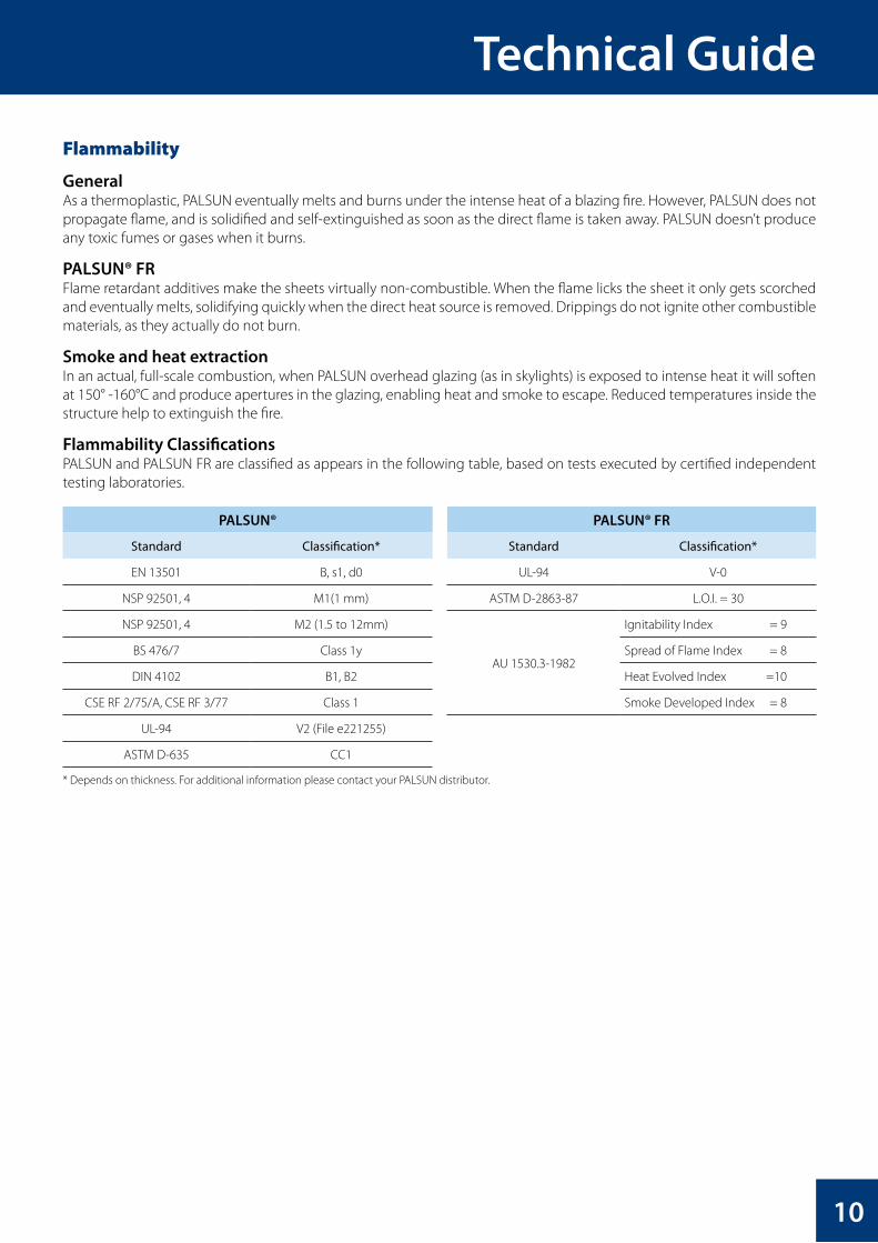
Flammability ClassificationsPALSUN and PALSUN FR are classified as appears in the following table, based on tests executed by certified independent testing laboratories.
PALSUN® PALSUN® FR
Standard Classification* Standard Classification*
EN 13501 B, s1, d0 UL-94 V-0
NSP 92501, 4 M1(1 mm) ASTM D-2863-87 L.O.I. = 30
NSP 92501, 4 M2 (1.5 to 12mm)
AU 1530.3-1982
Ignitability Index = 9
BS 476/7 Class 1y Spread of Flame Index = 8
DIN 4102 B1, B2 Heat Evolved Index =10
CSE RF 2/75/A, CSE RF 3/77 Class 1 Smoke Developed Index = 8
UL-94 V2 (File e221255)
ASTM D-635 CC1
* Depends on thickness. For additional information please contact your PALSUN distributor.

PALSUN®
11
Chemical Resistance
PALSUN sheets are compatible with many materials and chemicals, show limited resistance to others, and are incompatible with a third group, with which contact may be devastating. The mechanism of chemical attack on polycarbonate sheets differs significantly from the mechanism of corrosion of metals. Corrosion of metals results in a gradual loss of surface mate-rial as a result of electrolytic action by the relevant chemicals. In the cases where chemical attack on polycarbonate sheet occurs, all or a portion of a range of effects can be observed. Ethylene choride, chloroform, tetrachloroethane, m-cresol, pyridene and other chemicals can cause partial dissolution of polycarbonate. Swelling agents include benze, chloroben-zene, tetralin, acetone, ethyl acetate, acetonitrile and carbontetrachloride. Additional effects include color change and/or whitening. These effects may not always lead to product failure, especially for non-loaded sheets. Nevertheless, the level of measured mechanical properties will be reduced. The most critical effect of chemical attack is stress cracking or crazing, which may range in size from being visible to the naked eye to being only observable under a microscope. Stress cracks will always result in sheet failure which will eminate from areas of greatest stress (screws, fixings, bends, etc.).
Polycarbonate sheets are generally not recommended for use with acetone, ketones, ethers, and aromatic and chlorinated hydrocarbons in addition to aqueous or alcoholic alkaline solutions, ammonia gas and its solutions and amines.
Polycarbonate is resistant to mineral acids, many organic acids, oxidizing and reducing agents, neutral and acid salt solu-tions, many greases, waxes and oils, saturated, aliphatic and cycloaliphatic hydrocarbons and alcohols, with the exception of methol alcohol. The resistance of polycarbonate to water may be described as good up to approximately 60 °C. At higher temperatures, degradation occurs, the extent of which depends on time and temperature. Polycarbonate should therefore not be exposed for long periods of time to hot water. However, brief contact with hot water has no effect. For example, poly-carbonate tableware can be washed over 1000 times in a dishwashing machine with no adverse effects being observed.
The table that appears on the following pages lists the resistance of polycaronate sheet to a number of commonly encoun-tered chemicals and other corrosive media at room temperature. (Information on chemical resistance at higher tempera-tures will be supplied upon request). Where the chemical resistance varies with concentration, the results of tests at different concentrations is presented. The information on chemical resistance is based on our research and experience. (Note that information on compatable adhesives and sealants can be found in a separate leaflet which will be supplied upon request) It serves as a basis for recommendation. PALRAM Industries does not guarantee chemical resistance unless specific separate documentation is supplied.
For chemicals and corrosive media not depicted in the list, please contact your PALRAM representative. He will place you in contact with the PALRAM R&D & Technology Department.
The table on the following pages uses the following key:R - ResistantLR - Limited Resistance (gradual attack over time may occur)N - Not Resistant (rapid attack or attack over short time period will occur)
Chemical Resistance of PALSUN® Sheets at Room Temperature
The chemical resistance of PALSUN & PALTUF sheets, specified in the following pages, has been demonstrated in actual installations and/or laboratory tests. The information in the table is based on our research and experience. It should be con-sidered solely as a basis for recommendation, but not as a guarantee, unless specifically stated in separate documentation supplied by PALRAM Industries.

Technical Guide
12
ChemicalConcentration
%*Resistance Chemical
Concentration %*
Resistance
Acetaldehyde N Butane R
Acetic Acid 10 R Butter R
Acetic Acid 25 (concentrated) LR (N) Butyl Acetate N
Acetone N Butyl Alcohol (Butanol) R
Acetylene R Butylene Glycol R
Acrylonitrile N Butyric Acid N
Ajax Detergent R Calcium Chloride Saturated R
Allspice N Calcium Hypochlorite R
Allyl Alcohol LR Calcium Nitrate R
Alum (Aluminum Ammonsium Sulfate) R Calcium Soap Fat R
Aluminum Chloride Saturated R Camphor Oil N
Aluminum Oxalate R Carbolic Acid N
Aluminum Sulfate Saturated R Carbon Bisulfite N
Ammonia (Gas) N Carbon Dioxide Gas (Moist) R
Ammonia (Aqueous) N Carbon Disulfide N
Ammonium Carbonate LR Carbon Monoxide R
Ammonium Chloride R Carbon Tetrachloride N
Ammonium Fluoride N Castor Oil R
Ammonium Hydroxide N Catsup (Ketchup) R
Ammonium Nitrate R Caustic Potash (Potassium Hydroxide) N
Ammonium Sulfate Saturated R Caustic Soda (Sodium Hydroxide) N
Ammonium Sulfide N Chlorine Gas (Dry) LR
Amyl Acetate N Chlorine Gas (Wet) N
Amyl Alcohol LR Chlorobenzene N
Aniline N Chloroform N
Antimony Trichloride Saturated R Chocolate R
Aqua Regia (3 parts HCl:1 part HNO3) LR Chrome Alum Saturated R
Arsenic Acid 20 R Chromic Acid 20 R
Automatic Switch Grease R Cinnamon R
Automotive Waxes LR Citric Acid 10 R
Baby Lotion R Cloves N
Bacon Fat R Coal Gas R
Barium Chloride R Coca Cola LR
Battery Acid R Cocoa LR
Beer R Cod Liver Oil R
Beet Syrup R Coffee LR
Benzaldehyde N Cooking Oil R
Benzene N Copper Sulfate Saturated R
Benzoic Acid N Cresol N
Benzyl Alcohol N Cupric Chloride Saturated R
Betadine R Cuprous Chloride Saturated R
Bleach (Clorox) R Cyclohexane R
Blood and Blood Plasma R Cyclohexanol LR
Borax R Cyclohexanone N
Boric Acid R DDT R
Brake Fluid N Dekalin R
Bromine N Detergent (most) LR or R
Bromobenzene N Developing Solutions N or LR
Entries indicate the following: R - resistant, LR - limited resistance, N - not resistant*concentration of aquesous solution except where noted

PALSUN®
ChemicalConcentration
%*Resistance Chemical
Concentration%*
Resistance
Diamyl Phthalate N Kerosene R
Diesel Fuel R Lactic Acid 20 R
Diethyl Ether (Ethyl Ether) N Lacquers and Thinners R
Dimethyl Formaldehyde (DMF) N Laundry Detergents (Most) R
Dimethyl Sulfoxide (DMSO) N Ligroin (Hydrocarbon Mixture) R
Dinonyl Phthalate (plasticizer) LR Lime Solution (2%) or paste R
Doctyl Phthalate (plasticizer) LR Liquors or Liqueurs R
Dioxane N Linseed Oil R
Diphyl 5,3 LR Loctite R
Ethanol (Ethyl Alcohol) and Water 96 R Lubricating Oils (Most) R
Ethanol (Ethyl Alcohol) Pure LR Machine Oils (Most) R
Ethyl Amine N Magnesium Chloride Saturated R
Ethyl Acetate N Magnesium Sulfate Saturated R
Ethyl Bromide N Manganese Sulfate Saturated R
Ethylene Chloride N Margarine R
Ethylene Chlorohydrin N Mayonnaise R
Ethylene Dichloride N Meat R
Ethylene Glycol (Antifreeze) LR Mercuric Chloride Saturated N
Ferric Chloride Saturated R Mercury N
Ferrous Sulfate R Methane R
Fish and Fish Oils R Methanol (Methyl Alcohol) Pure LR
Floor Polish R Methylamine R
Formalin 10% R Methylcellusolve N
Formic Acid 10% (30%) R (LR) Methylene Chloride N
Freon TF R Methyl Ethyl Keton (MEK) N
Freon (all others) N Methylmethacrylate N
Fruit Juices and Pulp R Milk N
Gasoline N Mineral Oil R
Gear Oil R Motor Oils (Most) R
Glazers Putty R Mustard R
Glucose R Naphtha (Stanisol) R
Glycerine R Nickel Sulfate N
Glycerol R Nitric Acid 20 R
Glycols R Nitrobenzene R
Glutaraldehyde 50% R Nitropropane R
Grease, Automotive (Most) R Nitrous Oxide R
Heptane R Nutmeg N
Hexane R Oleic Acid N
Hydrazine N Onions R
Hydrochloric Acid 20 (Concentrated) R (N) Oxalic Acid 10 R
Hydrofluoric Acid 20 R Oxygen R
Hydrogen Peroxide 30 R Ozone R
Hydrogen Sulfide R Paprika R
Iodine (aqueous solution) 5 R Paraffin R
Iodine N Pentane LR
Inks (Most) R Pepper LR
Isoamyl Alcohol LR Perchloric Acid 10 (concentrated) N
Isopropyl Alcohol R Perchloroethylene R
Entries indicate the following: R - resistant, LR - limited resistance, N - not resistant*concentration of aquesous solution except where noted
13

Technical Guide
ChemicalConcentration
%*Resistance Chemical
Concentration %*
Resistance
Petroleum LR Sodium Sulfide N
Petroleum Ether LR Sodium Thiosulfate R
Petroleum Oil (Refined) R Spindle Oil R
Phenol N Stannous Chloride R
Phosphoric Acid 10 R Starch R
Phosphorous Oxychloride R Styrene N
Phosphorous Pentoxide 25 LR Sugar Saturated R
Phosphorous Trichloride N Sulfur Dioxide (Gas) R
Polyethylene R Sulfuric Acid <50 (50<70) R (LR)
Polyethylene Glycol R Sulfurous Acid 10 N
Potassium Acetate LR Sulfuryl Chloride N
Potassium Aluminum Alum (Sulfate) Saturated R Tapping Oil R
Potassium Bichromate R Tartaric Acid 30 R
Potassium Bromate R Tear Gas (Chloracetophenone) LR
Potassium Bromide R Terpineol N
Potassium Chloride Saturated R Tetrahydrofuran N
Potassium Cyanide N Tetralin N
Potassium Dichromate Saturated R Thiophene N
Potassium Hydroxide N Thyme R
Potassium Metabisulfite 4 R Titanium Tetrachloride R
Potassium Nitrate Saturated R Tobacco R
Potassium Perchlorate 10 R Toluene N
Potassium Permanganate 10 R Transformer Oils R
Potassium Persulfate 10 R Transmisssion Fluid R
Potassium Rhodanide Saturated R Trichloroacetic Acid 20 LR
Potassium Sulfate Saturated R Tricholorethylamine N
Propane R Trichloroethylene N
Propargyl Alcohol R Trichloroethylphosphate LR
Propionic Acid 20 R Tricresylphosphite N
Propionic Acid Concentrated N Trisodium Phosphate R
Propyl Alcohol (1-Propanol) R Turpentine LR
Pyridine N Urea R
Salad Oil R Vacuum Pump Oil R
Salt R Vanilla R
Silicofluoric Acid 30 R Vanillin R
Silicone Grease R Varnish N
Silicone Oil R Vaseline R
Silver Nitrate R Vegetable Juices R
Soap (Ivory) R Vegetable Oils R
Sodium Bicarbonate Saturated R Vinegar R
Sodium Bisulfate Saturated R Water (Demineralized or Sea) R
Sodium Bisulfite Saturated R White Spirit N
Sodium Carbonate Saturated R Wine, Whiskey, Vodka, Rum, Cognac R
Sodium Chlorate R Witch Hazel R
Sodium Chloride Saturated R Worcester Sauce R
Sodium Chromate R Xylene N
Sodium Hydroxide N Zinc Chloride R
Sodium Hypochlorite 5% Chlorine R Zinc Oxide R
Sodium Nitrate N Zinc Stearate R
Sodium Sulfate Saturated R Zinc Sulfate R
Entries indicate the following: R - resistant,. LR - limited resistance, N- not resistant. * Concentration of aque?ous solution except where notedThe chemical resistance information in this table is based on our research and experience and may be considered solelyas a basis for recommendation, but not as a guarantee, unless specifically furnished as such by PALRAM.
14

PALSUN®
Adhesives and Sealants
Adhesives and sealants are a special class of substances often required during installation or fabrication of PALSUN. The guidelines for their use, appearing below, must be followed.
1. Use only sealants, adhesives, rubber packing, sealing strips & gaskets that are compatible with PALSUN and approved by PALARM or its distributors. The most up to date information on compatible adhesives and sealants can be found in the technical brochure “Recommended Adhesives and Sealants for Palram Polycarbonate Products”, which is available at the global Palram website (www.palram.com).
EPDM rubber sealing strips and gaskets are the preferred choice, (though the use of neoprene is permitted) due to a longer life expectancy and durability.
2. Use of sealants, adhesives and other sealing products not included in the recommended list (Page 39) must receive the Manufacturer’s explicit approval, which can be obtained through your local distributor.
Important: Soft PVC gaskets and/or sealing strips are absolutely forbidden for use, as they are detrimental and may cause sheet failure.
3. Use of materials that are not on the list, and/or which have not received the Manufacturer’s explicit approval, may harm the sheets and void all warranties and any responsibility of the Manufacturer for the performance of PALSUN.
4. Your local distributor can provide additional information, and forward materials for testing and evaluation of their compatibility with the PALSUN sheets.
See “Joining” section (page 38) for additional specific details.
Selection of the Appropriate PALSUN Sheet
PALSUN sheets are manufactured in thicknesses of 1.0 to 12 mm.
PALTUF® SheetsIntended mainly for indoor use (transparent partitions, interior design applications, industrial shields, and Thermo-formed parts). They are also used in pavilions (exhibitions), or other temporary structures. Use of PALTUF sheets outdoors, for permanent applications, even in areas with mild UV radiation (Northern Europe, USA, Canada and the like) is not recommended.
Thin PALSUN® Sheetsfrequently used in temporary structures, (exhibitions, pavilions etc.). These products may also be used in conservatories or other horticultural / agricultural structures, where economy and lower cost are imperative. They are repeatedly used in Thermoforming applications, the forms generated render them rigid and suitable for special requirements, in signs and other advertising elements.
PALSUN® Sheets for Permanent Glazing ApplicationsThe recommended permanent installation method is inside a suitable supporting frame, made of metal (steel or alumi-num), wood or rigid PVC profiles. Glazing thickness is determined according to the sash width of said frame, the wind/snow loads dictated by the environmental conditions and the building codes existing at the for the place of the said structure.
15

Technical Guide
General Recommendations for Working With PALSUN®
Handling & Storage
1. PALSUN sheets should be transported and stored horizontally, on a flat, sturdy pallet whose dimensions are equal or larger than the largest of the sheets.
The sheets should be secured to the pallet during transportation and on-site handling. It is possible to stack the sheets with the longer sheets at the bottom and the shorter on top, leaving no unsupported overhang.
2. When moving a pallet with a forklift, always use forks as long as the sheets’ width. Shorter forks used on a wider pallet may cause damage to the sheets.
3. PALSUN sheets leave the factory in packages, wrapped in white, watertight polyethylene. The wrapping should be removed as close to the actual time of installation (or use) as possible.
Storage of the sheets should be in a covered, dry, ventilated place, away from direct sunlight and rain.
4. Avoid extended exposure to direct sunlight, which may cause excessive heat buildup. Long term heating may lead to softening of the protective polyethylene masking, fusing it to the sheet’s face and making removal difficult or even impossible.
5. Avoid leaving the sheets stored unwrapped. Dirt may accumulate on the sheets and/or their edges, attracted by electrostatic charges in the sheets, necessitating extra time and labor for cleaning before installation.
6. Whenever necessary to store the pallet in the open, cover it with white opaque polyethylene sheet, cardboard or any other insulating material, taking care to cover the stack completely.
Figure 7: Storing PALSUN® Sheets
16

PALSUN®
Fabrication - General Guidelines
Tools
PALSUN sheets can be fabricated with standard power tools for wood or metal, or some types of hand tools, providing they are smooth, well sharpened and have the required clearance for machining rigid plastics. Only speed regulated tools should be used. the highest possible speed that would not melt the sheet during operation, due to the heat buildup, gives the best results.High-Speed steel tools are adequate in most cases. Carbide-tipped tools are preferred for continuous production lines.Tools should be set up so that just the cutting edges should get into actual contact with the fabricated material, to reduce frictional heat buildup.
Cooling
Cooling is not required under standard machining conditions. When high-speed machining is necessary, clean water or compressed air can be used to cool the material and tool, and
remove the machining chips. Never use cooling oil or emulsions, as they may damage the PALSUN sheet. In order to avoid induced internal stresses generated by overheating, care must be taken to keep this heat buildup to the
absolute minimum.
Size Regulation
Due to the high thermal expansion rate of palsun, which is considerably greater than that of metals, glass or concrete,precision measurement checks should always be done at a fixed reference ambient temperature.
Protective Film (Masking)
The PALSUN polyethylene (PE) protective masking may be left on the sheet during most regular fabrication, to prevent damage to the surface.
Fabrication Markings
When necessary, mark sheets to be fabricated on the protective masking. If, for some reason, it is necessary to mark directly on the bare face of the sheet, use wax pencils or felt tipped marking pens.Marking the exposed surface by scratch marks with sharp objects may initiate fractures and induce failure under load.
Fabrication - Sawing & Cutting
A variety of power saws, either table mounted or portable can be used to saw PALSUN. Shearing or punching are also possible. Laser or water-jet cutting are less common but also possible techniques.
Table Mounted or Portable Circular Saws
These types of saw are widely used to saw PALSUN. There are two major workshop types and one portable type:
A Moving Table, Fixed Blade Bench Saw: is preferable for long, straight sawing. Radial Arm Saw: is generally used for “cross-cut” (width) or diagonal sawing. Portable Circular Saw: usually restricted for use on site for straight cutting, is slower and not as accurate as table saws.
This type of saw may be attached underneath a special bench to function as an on-site, limited operation fixed table saw.
17

Technical Guide
Circular Saw Blades
Should be fine toothed hollow ground, or preferably carbide tipped, triple chipped or alternate bevels (Alt 1 and Alt 2, see figures 9a & 9b below, respectively), with minimal blade body contact with the cut material. Such blades can offer clean, good quality cut.
Generally Accepted Recommendations for Circular Blade Specifications
Property Units Sign Value
Clearance angle α 10 – 20°
Rake angle γ 5 – 15°
Alternate double-bevel angle (Alt. 1) α° 45°
Alternate bevel angle (Alt. 2) β° 10 – 15°
Cutting speed - m/min (ft/min) 1,000 - 3,000 (3,300 - 10,000)
Rate of feed mm/sec (inch/sec) 30 (11/4)
Thin gauge: 1.5-2.5 mm tooth pitch (1/16” - 3/36” ) Teeth per mm (Teeth per in.) t 2.5 - 6 (10 - 12)
Heavy gauge: 3.2 - 12 mm tooth pitch (1/8” - 1/2” ) Teeth per mm (Teeth per in.) t 6.5 - 8.5 (3 - 4)
Notes:1. 2 Possible alternatives (Alt 1 & Alt 2, see figures 9a & 9b below) are supplied by different tools manufacturers as alternate beveled teeth for blades intended for cutting plastics, and both offer satisfactory cuts (line 3 in the table).2. For sawing thin gauge sheets of less than 2mm thickness, It is recommended to batch together 10 - 15 such sheets, with a thicker (3-4mm) bottom sheet for support.3. Shearing is a preferable option for cutting a single thin gauge sheet.
PALRAM Particular Circular Saw Cutting Recommendations
These recommendations are based on technical know-how, particular tests and vast practical experience accumulated during years of work. These recommendations are to be accepted only as general guidelines.
Figure 8: Typical Circular Saw Blade (segment)
Figure 9a: ALT1 - Alternate Teeth Configuration Figure 9b: ALT2 - Alternate Teeth Configuration
18

PALSUN®
Saw Blade Specifications for Cutting PALSUN up to 5mm Thickness
Property Units Value
Clearance angle mm (inch) 300 (12)
No. of teeth in blade 96
Thickness mm (inch) 2.2 - 3.2 (3/32” - 1/8” )
Teeth angles Rake: 45° Clearance: 15°
Tooth appearance
Alternating: Left - Right
Speed rpm 1800 - 2400
Saw Blade Specifications for Cutting PALSUN 6 to 12 mm Thickness
Property Units Value
Clearance angle mm (inch) 350 (14)
No. of teeth in blade 108
Thickness mm (inch) 2.2 - 3.2 (3/32” - 1/8” )
Teeth angles Rake: 10° Clearance: 15°
Tooth appearance
Alternating: Left - Right
Speed rpm 1800 - 2400
Notes:1. Teeth shapes sketches are not to scale. They should be considered to serve only as an indication.2. The PALSUN should be placed on a firm flat base and clamped into position during sawing.3. When sawing PALSUN it is recommended to leave the protective PE film on.4. If the cut sheet vibrates during sawing, cardboard sheet padding may be placed beneath it to absorb the vibrations.5. When sawing thin gauge PALSUN it is recommended not to cut single sheets by themselves, but saw a pack of 5-10 sheets at the time, clamped firmly together to a steady base.6. Low to moderate feed rate should be used when the sheets approach the blad, or vice versa. A feed rate that is too high can cause gumming, splitting or breaking of the sheet edges.
Band Saw
Band saws can be used for cutting PALSUN sheets of most thicknesses with acceptable results. Band saws are workshop tools. In PALSUN fabrication they are mostly used to cut formed parts or irregular shapes. It is possible to cut flat sheets in straight lines too, but in limited length and width, due to the tool’s limitations.
Thin gauge sheets are better sawed when stacked to a thickness of 10 -12 mm (0.4 - 0.5 in.) The preferred band saw blade should have slightly set teeth,
with 10 – 20 mm (0.4 - 0.8 in.) blade widths.
Figure 10: Typical Band Saw Blade Configuration
19

Technical Guide
Recommended Band Saw blade Properties
Property Sign Units Value
Clearance angle α 10 – 20°
Rake angle γ 5 – 15°
Cutting speed m/min (ft/min) 1,000 - 6,000 (1,950 - 3,300)
Rate of feed mm/sec (inch/sec) 20 (13/6)
Thin gauge: 1.5-2.5 mm tooth pitch (1/16” - 3/36” ) t Teeth per mm (Teeth per in.) 1.5 - 2.0 (12 - 18)
Heavy gauge: 3.2 - 12 mm tooth pitch (1/8” - 1/2” ) t Teeth per mm (Teeth per in.) 2.5 - 3.5 (7 - 10)
Notes:1. A band saw is suitable for cutting curved lines and 3-dimensional, formed parts.2. For cutting a few formed objects of the same shape, they must be firmly clamped together.3. A band saw cutting usually yields rougher finished edge, which must be smoothed by sanding and polishing. An endless belt sander is a preferred tool for such an operation.4. We recommend using a circular saw for better-finished edges, whenever possible.
Portables: Jigsaw or Saber Saw
Portable saws of these similar types use short movement, reciprocating blades, instead of one-direction orientation, continuous movement blades like those of circular or band saws, and are much slower in operation.
Chipping: Various sized chips are broken of on both edges of the sawing line, leaving the cut edges rough and uneven. Gumming: Chips and splinters from the advancing saw blade overheat during the sawing process, melt and create heaps
of cooled down material in front of the blade and on both sides of the cut. The swarf sticks to the edges leaving an ugly, rough edge finish, difficult to clean.
Jigsaw or saber saw cutting usually result in inferior finish of the cut edges, worse than the results achieved by a circular saw. We recommend that sanding and polishing of the cut edges should be used as a regular practice. An endless belt sander is the preferred tool for such an operation.
Sawing Tips
Portable saws of these similar types use short movement, reciprocating blades, instead of one-direction orientation, continuous movement blades like those of circular or band saws, and are much slower in operation.
Chipping: Various sized chips are broken of on both edges of the sawing line, leaving the cut edges rough and uneven. Gumming: Chips and splinters from the advancing saw blade overheat during the sawing process, melt and create heaps
of cooled down material in front of the blade and on both sides of the cut. The swarf sticks to the edges leaving an ugly, rough edge finish, difficult to clean.
Gummed material may also stick to the blade itself and cause seizure.The same uncontrolled heat that creates gumming, may also induce undue internal stresses along the edges of the cut, necessitating annealing of the sheet.
Recommended Remedies:
Choose the correct tooth size and pitch. Select a more appropriate saw speed. Lower the feed rate. Examine the sharpness of the blade. Examine the blade alignment. Cool the blade with compressed air when long cuts are required. Take frequent pauses during long production runs, to let the saw blade cool down. Begin sawing with the blade already running at the full recommended speed.
20

PALSUN®
Fabrication - Shearing & Punching
Shearing
A “Guillotine” power shear can be used for straight-line cuts. Easy, reasonably clean cuts can be obtained for thicknesses of up to 3 mm (1/8 in.). Beyond this, the material tends to draw, leaving uneven, stretched edge finish. We recommend cutting only one single sheet at a time.The shearing blade should be very sharp, with a single bevel of a 45° angle or less, or a hollow ground one of approximately 30°. Recommended clearance between blade and anvil (bed) should be kept to very close tolerances, as appear in the table below.
Recommended Gap Between Blade and Anvil (Bed) (5% of the Sheet Thickness)
Sheet Thickness Recommended Gap
mm Inch mm Inch
1 0.039 0.05 0.0002
1.5 0.059 0.075 0.0003
2 0.079 0.1 0.0004
2.5 0.098 0.125 0.0005
3 0.118 0.15 0.0006
The cut appearance may be adequate and suitable for many applications, but will not be similar in quality to the cut with a circular saw. Rough-finished cut edges can be improved by sanding, same as recommended for the other types of sawing.
As there are many power shears manufacturers it is recommended that before making a purchase, one should investigate the intended instrument capability, and confer with the manufacturer in reference to plastic sheets cutting. For accurate cutting it is recommended to cut only single sheets. Cutting more than one sheet at a time may cause a break in one of the sheets, and / or yielding inaccurately sized parts. Blade maintenance is an important factor in achieving a quality cut.
Nevertheless, if you decide to cut a few sheets together and breakage occurs, please check the following items:1. Try cutting fewer sheets at a time.2. Check blade condition: sharpness, uniformity and alignment.3. Change the gap between the blade and the bed to a more suitable one.
Our experience shows that cutting quality can be checked in advance by a simple trial cutting of an 80g-paper sheet:Acceptable – if the paper is cut cleanly, without tearing or crumpling.Unacceptable – if cut results in the paper torn and crumpled.
Punching
A technique usually used for cutting multiple holes and apertures (circular shaped or rounded) in thin or medium thickness PALSUN sheets quickly and uniformly. It uses a mechanical press with a quick moving, limited depth cutting male punch and static female anvil (base). Recommended for a maximal thickness up to 3mm (1/8 in.).
Punch cutting edges should be hollow-ground and very sharp for good quality cuts. Due to the tendency of edge drawing when punching, resulting in “blown-in” aperture edges, this “hole shrinkage” should be taken into consideration and provided for in cases of critically close tolerances. Exemplary values are about 0.2 mm (0.008 in.) shrinkage for a 12 mm (0.47 in.) hole, or 0.1 mm (0.004 in.) for a 6 mm (0.24 in.) hole, for a 3 mm (0.12 in.) thick sheet.
21
Technical Guide
Die Cutting
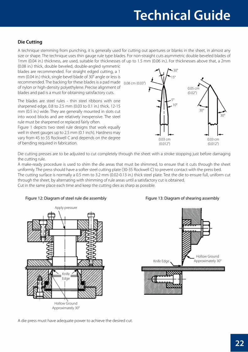
A technique stemming from punching, it is generally used for cutting out apertures or blanks in the sheet, in almost any size or shape. The technique uses thin gauge rule type blades. For non-straight cuts asymmetric double beveled blades of 1mm (0.04 in.) thickness, are used, suitable for thicknesses of up to 1.5 mm (0.06 in.). For thicknesses above that, a 2mm (0.08 in.) thick, double beveled, double-angled symmetric blades are recommended. For straight edged cutting, a 1 mm (0.04 in.) thick, single bevel blade of 30° angle or less is recommended. The backing for these blades is a pad made of nylon or high-density polyethylene. Precise alignment of blades and pad is a must for obtaining satisfactory cuts.
The blades are steel rules - thin steel ribbons with one sharpened edge, 0.8 to 2.5 mm (0.03 to 0.1 in.) thick, 12-15 mm (0.5 in.) wide. They are generally mounted in slots cut into wood blocks and are relatively inexpensive. The steel rule must be sharpened or replaced fairly often.Figure 1 depicts two steel rule designs that work equally well in sheet gauges up to 2.5 mm (0.1 inch). Hardness may vary from 45 to 55 Rockwell C and depends on the degree of bending required in fabrication.
Die cutting presses are to be adjusted to cut completely through the sheet with a stroke stopping just before damaging the cutting rule.A make-ready procedure is used to shim the die areas that must be shimmed, to ensure that it cuts through the sheet uniformly. The press should have a softer steel cutting plate (30-35 Rockwell C) to prevent contact with the press bed.The cutting surface is normally a 0.5 mm to 3.2 mm (0.02-0.13 in.) thick steel plate. Test the die to ensure full, uniform cut through the sheet, by alternating with shimming of rule areas until a satisfactory cut is obtained.Cut in the same place each time and keep the cutting dies as sharp as possible.
A die press must have adequate power to achieve the desired cut.
30°
30°30°
5°
0.08 cm (0.03”)0.05 cm(0.02”)
0.03 cm(0.012”)
0.03 cm(0.012”)
15°
10°
Apply pressure
Hollow Ground Approximately 30°
Hollow Ground Approximately 30°Knife Edge
KnifeEdge
Figure 12: Diagram of steel rule die assembly Figure 13: Diagram of shearing assembly
22

PALSUN®
Shearing & Punching Tips
1. Best results from these techniques are obtained by cutting a single sheet at a time. We recommend this. Cutting a batch of sheets may result in breakage and/or imprecise dimensions. Nevertheless, if one is committed to such a procedure, We recommend a few trial runs with small samples, and consultation with the shearing machine manufacturer.
2. A good indication for a quality cut is a trial cut of a regular 80 g paper page: If the outcome is a clean, straight cut, the actual result will be acceptable. If the cut paper is jagged, torn or crumpled- sharpen the blade and/or adjus the clearance and alignment.
3. We recommend that sanding and polishing of the cut edges should be used as a regular practice. Never leave on rough or jagged edged apertures as that may lead on to crazing and imminent failure.
Fabrication - Other Cutting Options
Laser Cutting
A Hi-Tech thermal technique reserved mainly for complex contours.A CO2 industrial laser can cut sheets up to 5 mm (0.2 in.) thickness.The cut can be done with or without masking, but often it needs pre-drying of the sheet in order to achieve bubblefree cut edges. It can be used for cutting intricate holes and patterns cleanly and precisely.Holes and cuts produced by a laser have slightly tapered edges with a finished appearance.However, a laser cut in sheets thicker than 2 mm (0.08 in.) may result in scorch marks and discoloration (yellowing) of the cut edges. When a laser is used for cutting, careful consideration and treatment is required before and afterwards, to compensate for its inherent properties.Annealing is recommended after laser cuttings, to remove the internal stresses created by the thermal process.
Routing
A versatile technique, enabling diversity of edge fabrications and trimming of PALSUN sheets, notably for parts too large or of irregular shape for a band saw. With sharp two-flute straight cutters it can generate very smooth edges.
The feed rate should be slow, to avoid excessive heat buildup and shattering. When routing, the moving object, whether the sheet or router, should be guided by a suitable jig. A jet of compressed air can be used to cool the bit and the sheet at the spot of cutting and assist in chip removal.
Static bench routers: Fast, strong and stable, for complex and accurate straight-line fabrications.
Portable routers: Less powerful, for smaller or on site jobs. Also used for trimming and edge fabrications of irregular shapes. Can perform certain small milling jobs like butt shaping on rectangular or round apertures or tongue and groove butt finish on thicker sheets.
Applications - Primary Edge Finishing
Quick and accurate trimming or finishing of straight-edged or curved cut PALSUN sheets. Easily produced straightedge corners or curved butts. Preparation of varied lap and butt joint fabrications.
Applications - Tooling
Routers: Universal, commercially available equipment. Routing cutters: new metalworking cutters, kept at utmost sharpness.
23

Technical Guide
Recommended Band Saw blade Properties
Property Units Value
Clearance angle 5 - 10°
Rake angle 0 - 10°
Router speed - w/o load rpm 15,000 - 22,000
Cutting speed m/min (ft/min) 100 - 500 (330 - 1640)
Feed rate mm/rev (inch/rev) 0.1 - 0.5 (0.004 - 0.07)
Routing and milling tips For clean, smooth routing work ensure cutter’s sharpness and faultless alignment before starting work. Compressed air jet cooling following the cutting head improves the culter’s speed, cut quality and blows the swarf away. Let the tool reach its maximum (unloaded) operating speed before commencing work.
Milling & Joining
A portable router, with suitable cutters, can be used for small milling jobs.
A standard woodworking jointer-planer, preferably with carbide or high-speed blades/cutters, can be used for trimming, acquiring good quality edge finish.Avoid excessive stock removal, which may result in shattering or rough edges. A cut of 0.4 mm (0.016 in.) or less per pass is recommended.
Finishing Recommendations for Well Done Sawing and Cutting
Unintended saw marks, rough or jagged corners, or uneven, drawn edges created by imperfect shearing may result in crazing and cracking, that can develop further to failure under load.Palram recommends finishing the edges of cut PALSUN sheets (or all types of plastics) by finishing the edges to a smooth appearance.This will ensure that no cracks will develop from the irregularities at the edges.Smoothing techniques are discussed in “Finishing” Section (page 26).
24

PALSUN®
Drilling
General Indications
Drill bits: Regular, new high-speed steel twist drills, or new carbide-tipped drills are suitable for drilling holes in PALSUN sheets of various thicknesses, as long as they are sharpened well. They are used mainly for bores up to 12 mm(1/2 “) diameter.
Larger holes may be drilled by flat, chisel edged drill blades with a triangular cutting tip, similar to those used in woodworking, kept always very sharp.Rake angle should be about 5° to avoid side friction. They are used mainly for bores from 12 to 20mm (1/2 “ to 13/16 “).Commercially available cutting cups or circle cutters of several types can be used for performing large round apertures.
Speed: Decrease the drill’s speed as hole diameter and / or sheet thickness gets larger. Drilling speed may vary due to actual conditions.
Feed rate: May vary due to actual conditions.
Drilling Speed and Feed Rate Change in Accordance with Bore Diameter
Hole Diameter Drill Speed Feed Rate
mm Inch 1 Inch 2 rpm mm/rev inch/rev
3 1/8 0.12 1500 - 1800 0.03 - 0.07 0.012 - 0.028
6 1/4 0.24 800 - 1500 0.03 - 0.07 0.012 - 0.028
10 13/32 0.4 500 - 1000 0.01 - 0.07 0.004 - 0.028
15 19/32 0.6 350 - 700 0.07 0.028
20 25/32 0.8 250 - 350 0.07 0.028
Recommended Drill Bit Configurations
Property Sign Units Value
Clearance angle 10 – 20°
Rake angle γ° 0 – 10°
Drill tip angle β° 110 – 150°
Helix angle α° 30°
Cutting velocity m/min (ft/min) 15 - 30 (49 - 98)
Notes: For small gauge sheets (1 - 2 mm or 0.04 - 0.08 in.) we recommend using flatter tip drill bits (β = 140 - 150°) for achieving a cleaner bore and less risk of chipping.
Figure 14a: Regular Drill Bit Figure 14b: Flat Chisel Edged Drill Blade
25

Technical Guide
Drilling tips and recommendations
Location: Locate holes no closer to the edges than 2 – 2.5 times the diameter of the pertinent hole, with a 10mm (0.4 in.) minimum.
Precision: It is imperative to keep the sheet (or stack of sheets) firmly clamped to a stable workbench (or a similar base) to avoid fluttering during drilling.
Cooling: Usually cooling is not required with regular drills. However, in cases of deep drilling, like putting perpendicular holes through the sheet’s edge, or when drilling through a
stack of sheets, cooling both the drill bit and the vicinity of the hole with a jet of compressed air is a good practice. It is also recommended, when drilling deep holes, to stop frequently, pull the drill out and clear the hole from swarf and
debris with compressed air.
Preventing internal stresses: Producing a clean, smooth bore, keeping heat buildup to the minimum, by the procedure described above, prevents excessive heat buildup, meltdown and gumming of the drilling dust and debris, and possible seizure of the bit. It also prevents undue internal stresses at the vicinity of the hole.
Honing and polishing the edge of the hole by mechanical or chemical means contributes to keeping the sheet stress-free, preventing cracking.
Mantainig the edge: Carbide tipped twist drill bits are preferable for long or continuous production runs. They are more durable and improve the edge quality.
Finishing
General Comments
Reasons, Means and TargetsThe final step in fabrication, finishing improves both the practical and esthetical properties of PALSUN sheet prior to assembly.
Grinding & PolishingThis is mostly done as a part of edge preparation.Practical objective: Rough, uneven, untended edges may be starting points for crazing and cracks after the PALSUN sheet is installed and subjected to day by day exposure to wind loads, UV radiation and thermal expansion & contraction, not to mention man-made punishment.Aesthetic objective: Nicely finished, smooth edges are a must for a quality appearance of the finished product, often installed with exposed edges.
Decorating:A type of finishing intended mostly for aesthetic appearance or for display purposes. Executed by painting, printing, films or hot stamping.
General Comments
GeneralA primary stage in edge finishing, rough or gagged edges and cutting tool marks created by a saw, shearing machine or a router, can be removed by grinding.
Grinding / Sanding RecommendationsA belt sander, equipped with a 400-500 grit belt, running at 20 - 30 m/sec (65 - 100 ft./sec), is the preferred option, applying low contact pressure during operation. Wet sanding and waterproof belts are preferable, as they prevents heat buildup, sanding dust accumulation, and prolong sanding belt life.
A reciprocating or orbital sander can also be used, but it can be applied only by the dry sanding method.
Manual Sanding can also be used, wet or dry, working with successive grit size abrasive paper (at first 100, then 280-grit silicon-carbide, and finally 400-600 grit sandpaper).
26

PALSUN®
Polishing
On the progressive stage in edge finishing, the sanded (or ground) edges are polished to a smooth finish.
1. Basic PolishingIt is done by abrasive-charged revolving wheels, made of cloth, leather or bristles. When used with a coolant, peripheral speeds of 10-15 m/sec (30-50 ft./sec) are recommended. When the wheel is operated dry lower speeds should be used.
Ashing: A polishing method in which wet rubbing compound like #00 pumice is applied to a rotating loose muslinwheel. Higher peripheral speeds of 20 - 22 m/sec (50 - 70 ft./sec) can be used, as overheating is not a problem inthis technique.
Buffing: A finishing step in which grease or wax filled abrasive bar is applied to rotating muslin wheel. Loose buffs are used for irregular shapes or for entering crevices. Usual buffing compounds are tripoli, rouge or other fine silica.
2. Advanced PolishingIt is achieved by using flannel or chamois wheels, with wax compounds with the finest abrasives such as whiting or levigated alumina. The wax fills the fine scratches or imperfections and protects the polished surface.
3. Final PolishingA. (Recommended) A small container with the solvent is heated to about 40 °C (104 °F) and the vapor created runs out
through a rubber hose, and is passed over near (about 50 mm or 2 in. distance) the roughly polished edges. A small amount of vapors is enough to achieve highly glossy edge surface. A repeated application is possible if required.
B. (Optional) A cloth soaked with MEK or Methylene Chloride, run carefully over the edges, can also produce acceptable results.
C. To minimize humidity blush after drying, add about 10% of a slow drying component (such as diacetone alcohol) to the basic solvent.
D. A note of precaution: when working with volatile or toxic solvents appropriate ventilation and respiratory protection are cardinal.
27

Technical Guide
Forming - Cold Forming
Cold Curving
1. PALSUN sheets can be cold bent or curved, within their minimal permitted bending radius, without damaging their mechanical performance. Moreover, based on our experience and observations, the internal stresses induced by curving give them extra strength and rigidity in both directions, as in pre-stressed concrete elements.
2. Rigidity and support spans increase progressively as the curve radius is reduced (down to the minimal permitted radius). A shallow curve should be considered virtually the same as a flat panel, while a deep curve may add significantly to the bridging ability.
Brake Forming
General Notes
1. PALSUN sheets can be cold-bent in a straight line (line bending). Standard metalworking tools, like a brake press, may be used for bending. The bending process results in a permanent plastic deformation. the degree and quality of this change depend on the thickness of the PALSUN sheet, the final bending angle required, and the actual tools used.
2. When brake forming of PALSUN is applied, the internal elastic stresses induced along the bent line reduce the mechanical properties, UV resistance, and chemical resistance of the sheet along the bending line. We recommend using the process for less demanding applications, and protecting the cold bent areas of the sheet from contact with aggressive chemicals or excessive forces.
3. Annealing (page 36) can reduce the residual stress level induced by the cold bending process, improving the sheet’s mechanical properties.
4. The maximum angles that can be obtained using this process depend on PALSUN sheet thickness, and the extent of the internal elastic strain. We recommend a 24-48 hours delay for sheet’s stress relaxation after bending. In order to achieve the desired angle, the sheet has to be bent 20-40 degrees in excess of that angle, depending on the angle and sheet thickness. During stress relaxation period immediately after bending, the bent sheet will expand and regain the required shape.
5. Certain types of sheets are not suited for either cold or thermal forming, like PALGARD (mar protected sheet). This type is supplied with a tough, scratchproof finish, which can not be bent and must be installed as is.
Practical Recommendations & Work Instructions
1. Preparations of the PALSUN Sheets and Tooling for Bending:
a. Cut the sheet to its required pre-bent size, after careful design. We recommend leaving the protective film on both sides during the cutting, edge preparation and cold bending operations.
b. Sand and polish the sheet’s edges to a very smooth finish. Rough edges or the tiniest fissure may initiate cracks and fractures at the vicinity of the bending lines, due to internal stresses induced by the bending process.
c. We recommend doing preliminary bending tests on small samples of the same (or varied) thickness of the intended sheet, and try a few different values of excess bending. After arriving at a satisfactory result you can start production.
d. It is advised to use special tooling, like blades and anvils, designed for plastic sheet bending. Standard metalworking blades and anvils are not necessarily suitable for bending plastic sheets. For plastics, we recommend using a special bending blade with a straight, rounded business edge. The edge radius should be about 4-6 mm (0.16 to 0.24 in.). The thicker the sheet, the larger edge radius required.The anvil channel outer “banks” (corners) should be rounded. Both blade and anvil are to be smooth and polished, with no projections, irregularities or rough edges.
Please note that an anvil channel for plastics bending is different than the one suitable for metalworking. It has wider, flat bottom and much steeper “banks”.
28

PALSUN®
2. Cold Bending Fabrication
a. Bending a sheet with an UV protected side (the printed protective film side) on the exterior of the bend gets best results. Therefore, unless otherwise requested, lay the sheet to be bent with the printed side face down.
b. For optimal results perform the brake forming quickly, with additional 20-40 degrees, as explained above, then leave for stress relaxation for 1-2 days.
3. Installation
a. Cold bent polycarbonate is more sensitive to mechanical or chemical abuse in the vicinity of the bend. Therefore, Palram recommend a design that offers better protection for bent areas from any detrimental influence.
b. Avoid putting additional strain on bent parts, like forcing a bent angle in or out to fit into an existing framework position.
Forming - Thermoforming
Pre-Drying
General Guidelines
Almost all types of PALSUN sheets are suitable for the various thermoforming (TF) procedures. However, due to a native small moisture content absorbed after manufacture, they demand a thorough pre-drying treatment prior to most the remoforming techniques. During this process, the sheet’s temperature will be raised to over 160 °C (320 °F). Avoiding this preliminary treatment may result in moisture blisters, marring the appearance of the finished product, and/or reduce its properties.
Almost all types of PALSUN sheets are suitable for the various thermoforming (TF) procedures. However, due to a native The recommended procedure entails using a recirculating air oven, operating at 120-125°C (250-260°F). The duration depends on sheet thickness. Higher thicknesses require longer periods in the drying oven.
Typical Pre-Drying Time in Oven for Various Thicknesses*
Sheet Thickness Drying Time at 125°C (260°F)
mm Inch Hours
1 0.04 1.5
2 0.08 4
3 0.12 7
4 0.15 12
5 0.2 18
6 0.24 26
8 0.32 45
Notes: Time for thicker sheets can be calculated through interpolation.
The sheets are put into an oven, with the protective film removed from both sides, and arranged 20-30mm 3/4”-1”) apart, to enable free air circulation. They can be stacked horizontally (on stays or suspended) or vertically- just so they will not be distorted or twisted.
The pre-drying process should be performed as close as possible to the actual forming. Fully dried sheets taken out of the oven and cooled down to roomtemperature may be workable within 1 to 10 hours (depending on relative humidity and temperature in the workshop).
Longer delay may necessitate repeated pre-drying session. A good idea is (if possible) leaving the pre-dried sheets in the switched-off oven until the actual thermoforming process. This way saves energy and time on the thermoforming apparatus.
29

Technical Guide
Guidelines to the Heating Process
Good quality thermoformed products can only be achieved through a careful and controlled heating process. All parts of the treated sheet should reach even, uniform temperature, achieved by a slow, controlled heating rate, avoiding sudden changes in air circulation and temperature. Such events may result in hot spots and possible distortions. the sheet’s edges must maintain the same forming temperature as the whole sheet.
Pre-heating of the clamping frame from120˚ to130˚C is recommended.
Temperature Regulation: Continuous regulation of the sheet’s temperature must be maintained inside the thermoforming device itself. PALSUN sheet (of any type) tends to cool quite quickly, and may need a regulating system for adding or dispersing of excess heat on the spot. The sheet’s temperature at the thermoforming zone (or the whole sheet) should always be kept above the “Glass Transition Temperature” (approx.150 °C) during the forming process.
Forcing the sheet to form at a lower temperature may induce detrimental internal stresses, reducing the sheet’s impact resistance and increasing its chemical sensitivity. Internal stresses are invisible and can be detected only by polarized light.
Annealing may solve the problem, but it is a complicated process, which is inefficient or impossible in most cases.
Protective Polyethylene (PE) masking in Thermoforming: Special PE masking is available for TF and should be ordered for sheets intended for TF. This masking may be left on the sheet using most thermoforming methods, and peeled off at the last moment. In case of regular masking, it should be removed prior to the thermal treatment, otherwise it may fuse into the sheet’s face.
Hot-Line Bending
General Guidelines
1. Description: A simple bending technique, used for forming local, straight line, one axis bent parts (such as corners, boxes, and machine guards). This type of bending is usually preferable (if possible) to cold line-bending.
2. The process: A bending device with localized heaters on one or two sides of the sheet to be bent is used. The “sandwiched“ two-sided heating method is preferable, since it retains the same temperature on both sides at the time. a one-side heater method requires turning the sheet over a few times during the heating period, in order to maintain optimal temperature on both sides.
Steps & Indications
One-sided heating method may suffice for sheets up to 3 mm (0.12 in.). Thicker sheets or more demanding cases require using two-sided heating. Keeping control of the sheet’s temperature limits of 155-167 °C (31-332 °F) is of the utmost importance.
Forcing the bend at lower temperatures will render the sheet fragile at the bend. This simple bending process enables working with regular sheets, without pre-drying. Experimenting with small samples before final execution is highly recommended.
Figure 15: Heat bending device
30

PALSUN®
PE Masking: When preparing for bending of regularly cladded sheets- peel off the masking on both sides of the sheet along the bend line for about 100 mm (4 in) on each side in TF prepared sheets. It is possible to process the sheet with the masking on, up to 5 mm (0.2 in) thickness. For sheets of 6 mm thickness or more the PE masking should be removed along the bending line, as described above. Always test a few samples before proceeding to production.
Heaters: Linear IR (Infrared) or resistance wires strip heating elements are used, preferably with heat reflectors. The width of the heated zone depends on the number of elements used, the spacing between them their specific thermal output and the distance from the target sheet.
Bending process: When the sheet has reached the required temperature the heaters are to be switched off. The sheet, held in pivoted clamps, preferably equipped with a caliper, is then bent to the required angle and secured there until it cools down and sets.
Note: It is recommended to perform the bend a few degrees tighter than the required angle, as it may “go back” a little after cooling down. The desired angle may be reached after a few trials.
Cooling is to be done in ambient air, taking care to avoid sudden drafts. These can cause distortion of the final product.
Minimal Hot-Line Bending Radius is 3 times the thickness of the bent sheet. Larger radii can be achieved by widening the heated zone.
Forming - Notes for Consideration
Local hot line bending (or any other localized heating, for the matter) induces internal stresses in the finished part, reducing the chemical resistance of the element at the bending line zone. Such treatment is therefore recommended for use in less demanding environments.Localized heating and cooling expansion/contraction characteristics are unpredictable in many cases. Short elements (up to 1.00 m or 3.0 ft) usually stay straight enough. Longer elements may distort to a concave shape (the outer edges are longer than the line-bent side due to uneven contraction).This phenomenon can be corrected or reduced by simple jigs or frames, which hold the part in the right position during the cooling period. Annealing (see special paragraph) may also correct this problem.It is always advised to fabricate experimental test samples to check feasibility of the bending operation.
Drape Forming
Description
A simple technique, using a single positive (male) or negative (female) mold, on which a heated PALSUN sheet is placed. The sheet, softened by appropriate thermal processing, sags and conforms to the shape of the mold under its own weight, or by slight mechanical pressure applied by hand. Drape forming is generally used to achieve simple, uniaxial, large curvature thermal forming.
The Process
Two main techniques, differing by the position of the mold during the first stage.
1. 1st Method: The sheet (without masking) is placed on top of the mold in its basic, flat state. Both sheet and mold are then slid into a hot-air circulating oven and heated to about 150-155?C (300-312?F). When the sheet (and mold) reaches the required temperature it sags and drapes over the heated mold. Both are then pulled out of the oven and quickly helped, by gloved hands, to conform more precisely to the mold. It is then allowed to cool down.
2. 2nd Method: The sheet is placed into a hot-air circulating oven (without masking), and heated to about 150-155 °C (300-312 °F). When the sheet reaches the required temperature it is quickly pulled out of the oven and placed on top of the mold. there the sheet sags, aided quickly by the gloved helping hands, and takes the accurate shape of the mold. For better results we recommend pre-heating the mold to about 80 -100 °C (175 -210 °F) before putting the heated sheet on top. Then it is, likewise, allowed to cool down.
31

Technical Guide
Vacuum Assisted Drape Forming
This technique can be assisted by vacuum and is then very similar in detail to the male (positive) straight vacuum forming.
Notes for Consideration
(These notes exclude the vacuum assisted drape forming)
1. There is no need for pre-drying in this technique, due to the lower operating temperature it requires.
2. The lower operating temperature leaves the exterior surface harder, helping to keep it mar free, with better optical quality.
3. The emphasis on quick operation during the final finishing touch to the heated sheet derives from the rapid cooling and setting properties of the PALSUN sheet once taken out of the oven.
The Molds
1. Regular molds: Can be made of metal (steel, aluminum or other) or wood, as long as it can stand the temperature inside the oven without visible distortion. The upper surface is usually covered by heat resistant felt, which will not mar the exterior sheet surface facing the mold face.
2. Premium molds: Finished products requiring premium optical quality (like visors, police shields, vehicles safety glazing etc.) need molds with very smooth, glossy, heat resistant upper surface. They can be made of polished steel, aluminum, glazed ceramics or glass.
Stage 1
Clamped, heated PALSUN sheet can be pulled over the mold, or the mold can be forced into the sheet.
Stage 3
Final wall thickness distribution in the molded part.
Stage 2
Once the sheet has formed a seal around the mold, a vacuum is drawn to pull the sheet tightly against the old surface.
Figure 16: Vacuum Assisted Drape Forming
32

PALSUN®
Drape Forming
General Guidelines
Vacuum forming is the most versatile and widely used thermoforming process. The equipment required is simpler and less costly to operate than most pressure or mechanical thermoforming techniques. Good results are quite easily attained with pre-dried sheets and decent vacuum-forming equipment.Reduction in Thickness:The Vacuum forming procedure generally stretches parts of the processed sheet to smaller thickness at varied areas (according to the system chosen). Always take this into consideration when choosing the primary sheet thickness.
Molds:Prototype or Limited Production Molds can be prepared of smoothed plaster, hardwood, reinforced epoxy or polyester resins (or a combination of them).High quality finish or full production run molds for yielding quality results or quick release operation tools have to be heated to working temperatures of 120 - 130 °C. Higher mold temperature (within the limits) gets better product’s finish. Polished aluminum or steel are preferable materials.
Mold Corners: Design the mold with rounded “sharp” corners, with radii at least as large as the processed sheet thickness, to avoid excess thinning or webbing during forming.
Mold Release: Good release of the molding can be achieved by designing the mold with a draft angle of at least 4 to 6 degrees on the upright walls. Allow for a molding shrinkage of about 1%.
Air Evacuation Through the Mold: Vacuum forming operates on suction principle, creating vacuum underneath the processed sheet. Suction is obtained through small holes put into the mold face. To prevent marking the molding, holes diameter on the exterior should not surpass 0.8 mm (0.031 in.). On the interior side of the mold the hole could be enlarged, to speed up air evacuation.
Male (positive) or Female (negative) Molds: Vacuum forming can be performed on male or female molds, using different equipment and technique, with different results.Male Mold Forming: A heated sheet is lowered over a protruding mold and stretched down to the bottom, then air is evacuated through the mold and creates vacuum, which “sucks” the stretched sheet until it clings to the mold face.(Actually similar to vacuum assisted drape forming).Female Mold Forming: A heated sheet is placed over the cavity of the negative mold, then air is sucked through the mold. The vacuum “sucks” the sheet until it clings to the inner face of the mold.
Male Mold: Its use results in thicker bottom and thinner walls. The internal finish of the final product is better. This type of mold is suited for deeper drawing (up to 4:1 depth to diameter ratio). It usually has a single protrusion, in a simple or more elaborately shaped forming. This is a relatively complex and slow technique needs a longer production cycle.
Female Mold: Its use results in thinner bottom and thicker walls and edges. The exterior finish of the final product is better. It can be used in a single cavity (simple or elaborate), especially suitable for multi-cavity, smaller spacing moldings. Its use results in edges thinning during deep draw, thus most suitable for simple, shallow, quick release designs, with a relatively fast production cycle.
Automatic Vacuum-Forming Machines: These are preferable in use, gripping the worked-on sheet on all sides during the process. It is notably important when working on thin 1 or 2 mm (0.04 or 0.08 in.) thick sheets. Thin sheets tend to shrink up to 5% during the thermal processing and the cooling period, and must be firmly held in a fixed size frame.When a sheet is inserted into the vacuum-forming machine, verify that the UV protected side is properly oriented to suite the finished product. Vacuum forming usually requires pre-drying of the sheets. It can also be carried out without pre-drying, in shallow molds and careful treatment. In that case the sheet temperature should not exceed 160 °C (320° F). Uneven heating, resulting in localized hot spots, over 160-165 °C (320-330° F), may cause bubbles to appear at the overheated zone.
33

Technical Guide
Various Vacuum Forming Techniques
1. Straight Vacuum Forming: In straight vacuum forming, the PALSUN sheet is clamped in a frame and heated until it reaches an elastic state. It is then placed over the female mold cavity, and air is then sucked out of the cavity by vacuum. The atmospheric pressure forces the hot sheet against the contours of the mold. When the PALSUN sheet has cooled down sufficiently, the formed part can be removed from the mold.
Thinning at the upper edges of the part usually occurs with relatively deep female molds. The hot sheet being drawn first to the mold center causes thinning. The sheet area at the edges of the mold stretch the most, thus becomes the thinnest section of the formed item. Straight vacuum forming is normally used for simple, shallow designs. See the figures below.
Other Thermoforming Techniques: Other, more specialized, thermoforming techniques use vacuum along with other power assistance, and others depend on different mechanical principles. These techniques were developed for typical ap-plications or to achieve certain results:
2. Matched Mold Forming: A heated sheet is placed between two matching male/female heated molds, which are then pressed to each other. Trapped air pockets are vented by vacuum through holes in the molds. System enables very good detailing of surfaces, but is relatively costly due to need of accurate tooling and closer tolerance.
Stage 1
A clamped, heated sheet is forced down into the mold by air pressure after a vacuum is drawn in the mold.
Stage 3
Areas of the sheet that touch the mold last are the thinnest.
Stage 2
Plastic sheet cools as it contacts the mold.
Figure 17: Straight Vacuum Forming
Figure 18: Matched-Mold Forming
Stage 1
The heated PALSUN sheet can be clamped over the female die, as shown, or draped over the mold form.
Stage 2
Vents allow trapped air to escape as the mold closes and forms the part.
34

PALSUN®
3. Trapped-Sheet Contact-Heat Pressure Forming: The process is based on similar principles as vacuum forming, except that both air pressure and a vacuum assist are used to force the PALSUN sheet into a female mold. It uses lower working temperature, and has a quicker production cycle. Other benefits are better dimensional control and finer finish.
The figures below describe the steps in the process.
4. Plug Assisted forming: Available in varied pressure/vacuum systems for deeper drawings and better control over wall thickness.
5. Pressure-Bubble Plug-Assist Vacuum Forming: The pressure-bubble plug-assist vacuum forming technique is used when a sheet is to be formed into deep articles that must have good thickness uniformity. The framed sheet is heated, then controlled air pressure is used to create a bubble. (See the figures below.) When the bubble is stretched to a predetermined height, the male plug-assist (normally heated) is lowered to force the stretched sheet into the cavity. Plug speed and shape can be varied for improved material distribution.
Stage 1
A flat, porous plate allows air to be blown through its face.
Stage 1
The PALSUN sheet is heated and sealed across the mold cavity.
Stage 3
Air is blown through the plate to force the PLSUN into the mold cavity.
Stage 3
A plug shaped roughly to the cavity contour presses downward into the bubble, forcing it into the mold.
Stage 2
Air pressure from below and a vacuum above force the sheet tightly against the heated plate.
Stage 2
Air is introduced, blowing upward into an evenly stretched bubble.
Stage 4
After forming, additional pressure may be exerted. Steel knife can be used for seal and subsequent trim if additional pressure is exert-ed at this stage.
Stage 4
When the plug reaches its lowest point, vacuum is drawn to pull the plas-tic against the mold walls. Air can be ntroduced from above to aid forming.
Figure 19: Trapped-Sheet Contact-Heat Pressure Forming
Figure 20: Pressure-Bubble Plug-Assist Vacuum Forming
35

Technical Guide
6. High air-pressure blows-up a heated sheet through a shaped aperture, resulting in Free Forming, a smooth, freeform bubble shape, without touching mold’s face. Both interior and exterior surfaces remain smooth and blemish-free.
7. Mechanical Forming: This method uses no molds, only mechanical means like bending, stretching or holding to form parts of relatively simple design.
Troubleshooting Tips for Thermoforming
Please consult the Faults & Remedies for Thermoforming Table (page 37) at the end of this manual.
Forming - Annealing
Cold fabrication, or various thermoforming systems of the PALSUN sheets, may induce detrimental internal stresses, which may eventually cause failure, and have to be relieved by annealing.Annealing is achieved by heating the fabricated objects evenly in an air-circulating oven up to 120 to 130 °C, and leaving them inside for about an hour for every 3mm thickness. (Example: 6 mm thick formed part- 2 hours of “baking”.)After the “baking” period, the parts should be left to cool down slowly to the ambient temperature. It is preferable to let it cool inside the closed oven.
Forming - Tips about PALSUN Thermoforming
Consistent part-to-part uniformity is better ensured if the sheet blanks prepared for the thermoforming process are cut from the basic sheet always at the same direction.Best results in thermoforming are achieved when parts are heated to temperatures just above the HDT (150 °C- 300 °F).Thermoforming parts below the HDT temperature induces undue internal stresses.Secure the cooling area for thermoformed parts against undue drafts. Uneven cooling may result in warping and/or curling of parts.Assure precise and systematic control over oven temperature and heating time.PALSUN MR and FR are not recommended for use in thermoforming. The bending and stretching involved during the pro-cess will break and crack the protective coating.
Examples of free-form shapes that can be obtained with openings.
Figure 21: Free Forming
36

PALSUN®
Fault and Remedies in Thermoforming Practice
# Recognized Fault Probable Cause Proposed Treatment
Hot Lin
eB
end
ing
Drap
eForm
ing
VacumForm
ing
FreeB
lown
1Apparent bubbles in sheet
Moisture content too high Pre-drying + + + +
2 Working temp. too high Decrease working temp. + + +
3
Hair fissures, fragile parts
Part overheated Decrease heating period + +
4 Mold under-heated Increase mold temp. +
5 Late extraction of part Diminish cooling cycle +
6 Vacum speed too high Reduce vacum rate +
7 Mold corners too sharp Round sharp corners +
8 Basic sheet size too small Increase sheet size +
9
Webbing
Erratic heating Prevent hot or cold spots +
10 Mold lead inadequate Check spacing-min. depth x 2 +
11 Vacum speed too high Reduce vacume rate +
12 Basic sheet size too large Clamp/mold spacing <50mm +
13Blurred or partial detailing
Vacum too weak Seal leaks/add vacum holes +
14 Sheet rigid, under-heated Extend heating period or temp. +
15
Product sticks to mold
Mold overheated Decrease mold temperature +
16 Product release delayed Shorten release period +
17 Draft angle too steep Enlarge draft angle up to 4-6° +
18
Marked zones on product
Irregular finish of mold Treat mold to consistent finush +
19 Suction holes misplaced Install new, better placed holes +
20 Sheet overheated Decrease heating period/ temp. + +
21Exterior flaws / roughness
Dirt/ grime on sheet / mold Wipe/Vacum-clean mold/sheet + +
22 Suction holes misplaced Install new, better placed holes +
23
Inconsistent shape of part
Mold/ brace under-heated Extend pre-heat of mold/brace +
24 Irregular heating/ cooling Prevent drafts, fix faulty heater + + + +
25 Product release delayed Shorten release period +
37

Technical Guide
Joining
General Guidelines
PALSUN sheets, or parts made of them, can be assembled and joined to each other, or to other materials, with the help of varied techniques and materials.Assembly can be executed by bonding, cementing, or mechanical fastening.Each technique has its variations, with different properties, merits and shortcomings. Certain preparations (by milling or routing) may be required improve the quality of the joints both aesthetically and practically.
Mechanical Joints
Machine Nuts & Bolts or Self-Tapping Screws must be supplemented by wide washers and EPDM gaskets forpadding and load spreading (see more comprehensive description further on).
Riveting: Same indication for washers and gaskets as in screws. (see more comprehensive description further on).
Chemical Joints
PALSUN sheets can be joined to each other or to other materials by bonding or cementing, with or without prior prepara-tion. Most such joints are suitable for relatively small to medium sized jobs. We present here a few possible options:
Joint Design: The joint details should be thought over carefully, verifying that the bonding area spreads the intended loads equally, and the major stresses are either in tension or shear, so as to minimize separation and peel stresses.
Lap Joints: They are most frequently used technique, in various designs, especially in relatively thin gauge parts. The sheets’ edges overlap and are bonded together (in the suitable variation-fits for all sheet thicknesses). Some variations require rout-ing or milling at the joints for proper execution.
Figure 22: Typical Lap JointsB,D,F, superior to A,C, E, / G,H corner lap joints
38

PALSUN®
PrintingPALSUN is suitable for all printing methods which are applicable to rigid sheets. It has been tested and approved by leading digital printer manufacturers, achieving excellent results in all parameters. Clear PALSUN sheets match the high clarity of other thermoplastic sheets, yet offer far better adhesion properties and ease of printing with no requirement for any further surface treatment.
Direct Digital PrintingWide format (Roll-to-roll) and flatbed printers use various ink and ink curing technologies to allow high quality printing at relatively high speeds. High quality digital printing depends on various factors: Printer capabilities
Ink technology and quality
Type of printing substrate and quality
Machine operator
PALSUN is suitable for use with UV curing and solvent-based digital inks, and for IR drying when water-based inks are used. PALSUN would retain its clarity or tint, even after intense UV curing.
Protective Film MaskingThe protective polyethylene film mask helps prevent surface abrasion and stains. However, removing the protective film may cause an increase of static electric charge, which can affect ink coverage. Therefore, after peeling the film away from the sheet, the static electricity that has built up in the sheet should be discharged using an ionized gun or a suitable device provided by the printer manufacturer.
Cleaning PALSUN® and Preparing for PrintingThe surface should be clean before printing. Carefully inspect each panel to ensure there is no: dust, fingerprints, residue or other problematic substances that may affect ink coverage or adhesion. If needed, the PALSUN should be cleaned with a damp rag, or with isopropyl alcohol.
Ink AdhesionPALSUN is suitable for all types of inks: aqueous, solvent based, and UV curable. This suitability is affirmed by major printer OEM’s, including HP, AGFA, Océ, Gandy Digital, Mutoh, and more. For compatibility information and recommendations, please consult the printer manual or contact the printer manufacturer.
Ink DryingThere are two main technologies used for ink drying in digital printing:IR (Infrared) – PALSUN’s short and long term service temperatures are 120°C and 100°C respectively, which make it highly suitable for printers with IR drying tunnels.UV (Ultraviolet) – PALSUN is immune to long term UV exposure and is suitable for UV curing.
Print Head AdjustmentThe distance between the print head and the substrate can have a significant affect on print quality. Manufacturer specifications, combined with and operator experience, should determine print head distance from the substrate.The suggested starting distance should not be more than 2 mm from the print head to the substrate.

Technical Guide

PALSUN®

Technical Guide

©1997 PALRAM Industries Ltd.PALSUN and PALTUF are registered trademarks of PALRAM Industries Ltd. 11.10
Inasmuch as PALRAM Industries has no control over the use to which others may put the material, it does not guaranteethat the same results as those described herein will be ob- tained. Each user of the material should make his own tests to determine the material's suitability for his own particular use. Statements concerning possible or suggested uses of the materials described herein are not to be construed as constituting a license under any PALRAM Industries patent covering such use or as recommendations for use of suchmaterials in the infringement of any patent. PALRAM Indus-
tries or its distributors cannot be held responsible for anylosses incurred through incorrect installation of the mate- rial. In accordance with our company policy of continual product development you are advised to check with your local PALRAM Industries supplier to ensure that you have.obtained the most up to date information
PALRAM Europe Ltd.Tel u (44) 1302 380776Fax u (44) 1302 380788E-mail u [email protected] u www.palram.com
PALRAM Israel Ltd.Tel u (972) 4 8459 900Fax u (972) 4 8459 980E-mail u [email protected] u www.palram.co.il
PALRAM Industries Ltd.PALRAM Americas Inc.Tel u 610 285 9918Fax u 610 285 9928E-mail u [email protected] u www.palramamericas.com