Palo Verde, Units 1, 2, & 3, Third 10-Year Interval …Relief Requests PRR-01, PRR-03, PRR-04 and...
137
10 CFR 50.55a(f)(5) 10 CFR 50.55a(a)(3) A--P A subsidiary of Pinnacle West Capital Corporation Dwight C. Mims Mail Station 7605 Palo Verde Nuclear Vice President Tel. 623-393-5403 P.O. Box 52034 Generating Station Regulatory Affairs and Plant Improvement Fax 623-393-6077 Phoenix, Arizona 85072-2034 102-05732-DCM/RJR August 13, 2007 ATTN: Document Control Desk U.S. Nuclear Regulatory Commission Washington, DC 20555-0001 Dear Sirs: Subject: Palo Verde Nuclear Generating Station (PVNGS) Units 1, 2, and 3 Docket Nos. STN 50-5281529/530 Third 10-Year Interval Pump and Valve Inservice Testing Program Relief Requests PRR-01, PRR-02, PRR-03, PRR-04, PRR-05, PRR-06, PRR-07 and VRR-01 Pursuant to 10 CFR 50.55a(f)(5)(i), Arizona Public Service Company (APS) has revised the Palo Verde Nuclear Generating Station (PVNGS) pump and valve inservice testing program for the third 10-year test interval for Units 1, 2, and 3. The third interval begins on January 15, 2008. Enclosure 1 provides a summary of the Palo Verde pump and valve inservice testing (IST) program and contains the relief requests required for the third interval. Each of these relief requests were previously authorized for Palo Verde's second interval by the NRC Safety Evaluation dated July 8, 1999, except PRR-02. Relief request PRR-02 is being requested because the installed instrumentation does not meet the new accuracy requirement from Table ISTB-3500-1 of the 2001 Edition with the 2003 Addenda of the ASME OM Code. Enclosure 2 is an information copy of the revised IST program. APS requests approval of the relief requests prior to the start of the third inservice testing interval which will begin on January 15, 2008. This letter contains no new commitments. If you have any questions about this request, please contact Glenn A. Michael at (623) 393-5750. Sincerely, A member of the STARS (Strategic Teaming and Resource Sharing) Alliance Callaway * Comanche Peak 0 Diablo Canyon 0 Palo Verde * South Texas Project * Wolf Creek W7
Transcript of Palo Verde, Units 1, 2, & 3, Third 10-Year Interval …Relief Requests PRR-01, PRR-03, PRR-04 and...

10 CFR 50.55a(f)(5)10 CFR 50.55a(a)(3)
A--P A subsidiary of Pinnacle West Capital Corporation
Dwight C. Mims Mail Station 7605Palo Verde Nuclear Vice President Tel. 623-393-5403 P.O. Box 52034Generating Station Regulatory Affairs and Plant Improvement Fax 623-393-6077 Phoenix, Arizona 85072-2034
102-05732-DCM/RJRAugust 13, 2007
ATTN: Document Control DeskU.S. Nuclear Regulatory CommissionWashington, DC 20555-0001
Dear Sirs:
Subject: Palo Verde Nuclear Generating Station (PVNGS)Units 1, 2, and 3Docket Nos. STN 50-5281529/530Third 10-Year Interval Pump and Valve Inservice Testing ProgramRelief Requests PRR-01, PRR-02, PRR-03, PRR-04, PRR-05, PRR-06,PRR-07 and VRR-01
Pursuant to 10 CFR 50.55a(f)(5)(i), Arizona Public Service Company (APS) has revisedthe Palo Verde Nuclear Generating Station (PVNGS) pump and valve inservice testingprogram for the third 10-year test interval for Units 1, 2, and 3. The third interval beginson January 15, 2008. Enclosure 1 provides a summary of the Palo Verde pump andvalve inservice testing (IST) program and contains the relief requests required for thethird interval. Each of these relief requests were previously authorized for Palo Verde'ssecond interval by the NRC Safety Evaluation dated July 8, 1999, except PRR-02.Relief request PRR-02 is being requested because the installed instrumentation doesnot meet the new accuracy requirement from Table ISTB-3500-1 of the 2001 Editionwith the 2003 Addenda of the ASME OM Code. Enclosure 2 is an information copy ofthe revised IST program.
APS requests approval of the relief requests prior to the start of the third inservicetesting interval which will begin on January 15, 2008.
This letter contains no new commitments. If you have any questions about this request,please contact Glenn A. Michael at (623) 393-5750.
Sincerely,
A member of the STARS (Strategic Teaming and Resource Sharing) Alliance
Callaway * Comanche Peak 0 Diablo Canyon 0 Palo Verde * South Texas Project * Wolf Creek W7

ATTN: Document Control DeskU.S. Nuclear Regulatory CommissionThird 10-Year Interval Pump and Valve Inservice Testing Program Relief RequestsPage 2
DCM/GAM/RJR/gt
Enclosure 1 - Palo Verde Pump and Valve Inservice Testing Program SummaryAttachment to Enclosure 1 - Third 10-Year Interval Pump and Valve Inservice Testing
Program Relief Requests PRR-01, PRR-02, PRR-03, PRR-04, PRR-05, PRR-06, PRR-07 and VRR-01
Enclosure 2 - Information Copy of the Revised Third 10-Year Interval Pump and ValveInservice Testing Program
cc: B. S. Mallett NRC Region IV Regional AdministratorM. T. Markley NRC NRR Project ManagerG. G. Warnick NRC Senior Resident Inspector for PVNGS

ENCLOSURE I
Palo Verde Pump and ValveInservice Testing Program Summary

Palo Verde Pump and Valve Inservice Testing Program Summary
Section 50.55a of Title 10 of the Code of Federal Regulations (10 CFR), requires thatinservice testing (IST) of certain American Society of Mechanical Engineers (ASME)Code Class 1, 2, and 3 pumps and valves be performed at 120-month (10-year) ISTprogram intervals in accordance with the specified ASME Code incorporated byreference in the regulations, except where alternatives have been authorized or reliefhas been requested by the licensee and granted by the Nuclear RegulatoryCommission (NRC or the Commission) pursuant to paragraphs (a)(3)(i), (a)(3)(ii), or(f)(5)(iii) of 10 CFR 50.55a. In accordance with 10 CFR 50.55a(f)(4)(ii), Arizona PublicService Company (APS) is required to comply with the requirements of the latest editionand addenda of the ASME Code incorporated by reference in the regulations 12 monthsprior to the start of each 120-month IST program interval. In accordance with50.55a(f)(4)(iv), inservice tests of pumps and valves may meet the requirements setforth in subsequent editions and addenda that are incorporated by reference in 10 CFR50.55a(b), subject to NRC approval. Portions of editions or addenda may be usedprovided that all related requirements of the respective editions and addenda are met.
The Palo Verde Nuclear Generating Station (PVNGS) Pump and Valve InserviceTesting Program was developed in accordance with the 2001 Edition with the (w/) 2003Addenda of the ASME OM Code. The Palo Verde third 10-year IST interval for all threeunits begins on January 15, 2008.
The attachment to this enclosure contains the relief requests required for the thirdinterval. Enclosure 2 is an information copy of the revised IST program.
Relief Requests PRR-02, PRR-06, PRR-07 and VRR-01 are being submitted under theprovision of 10 CFR 50.55a(a)(3)(i), wherein the proposed alternatives would provide anacceptable level of quality and safety.
Relief Requests PRR-01, PRR-03, PRR-04 and PRR-05 are being submitted under theprovisions of 10 CFR 50.55a(f)(5)(iii), wherein inservice testing that is impractical for thefacility.
Each of these relief requests were previously authorized for Palo Verde's secondinterval by the NRC Safety Evaluation dated July 8, 1999, except PRR-02. Reliefrequest PRR-02 is being requested because the installed instrumentation does notmeet the new accuracy requirement from Table ISTB-3500-1.
The attached APS requests demonstrate that: (1) the proposed alternatives provide anacceptable level of quality and safety or (2) conformance is impractical for the facility.
APS requests approval of the relief requests prior to the start of the third inservicetesting interval which will begin on January 15, 2008.
Page 1

Attachment to Enclosure 1
Third 10-Year Interval Pump and ValveInservice Testing Program
Relief Requests
PRR-01, PRR-02, PRR-03, PRR-04,PRR-05, PRR-06, PRR-07 and VRR-01

PUMP RELIEF REQUEST PRR-01
Relief Request In Accordance with 10 CFR 50.55a(f)(5)(iii)
-- Inservice Testing Impracticality -
Essential Auxiliary Feedwater Pump Flow Rate Measurement
ASME Components Affected:Pump ID Pump Description Code Class Pump Group
AFA-PO1 Essential Auxiliary 3 BFeedwater Pump(Turbine-Driven)
AFB-PO1 Essential Auxiliary 3 BFeedwater Pump(Motor-Driven)
Component/System Function:
The essential auxiliary feedwater (AF) pumps supply water to the steam generatorsduring an accident. They also can be used to supply feedwater to the steam generatorsduring plant startup and shutdown.
Applicable Code Edition and Addenda:
ASME OM Code 2001 Edition w/2003 Addenda
Applicable Code Requirement(s):
ISTB-3300, "Reference Values," ISTB-3300(e)(2), "Reference values shall beestablished within ± 20% of pump design flow for the Group A and Group B tests, ifpracticable. If not practicable, the reference point flow rate shall be established at thehighest practical flow rate."
ISTB-5122, "Group B Test Procedure," "Group B tests shall be conducted with thepump operating at a specified reference point. The test parameter value identified inTable ISTB-3000-1 shall be determined and recorded as required by this paragraph."
ISTB-5122(b), "The differential pressure or flow rate shall be determined and comparedto its reference value."
Impracticality of Compliance:
The Code requirements to establish the Group B reference point flow rate at the highestpractical flow rate and operate the pump at a specified reference point (i.e., fix the flow
Page 1

PUMP RELIEF REQUEST PRR-01
to a specified value) are impractical since this is a fixed resistance recirculation pathwith no flow instrumentation provided. When the pump operates on minimum flowrecirculation (approx. 260 gpm) the specified reference point is essentially achieved bythe recirculation lines fixed resistance. To establish the fixed resistance the minimumflow recirculation line contains an administratively controlled locked-throttled drag valveand a locked open manual isolation valve. The use of an ultrasonic flowmeter wasevaluated and determined impractical due to the difficulty in establishing an applicationspecific 2% calibration on the AF mini-flow piping. Allowing the flow to remain fixed bythe locked-in resistance increases the potential for repeatable test results anddegradation monitoring rather than changing the resistance based on ultrasonic flowmeter readout fluctuations. With this understanding, there is little value added ininstalling flow instrumentation to measure and record the flow with instrumentation thatmeets ISTB-3510 requirements. The fixed resistance methodology is repeatable fromtest to test and accomplishes the same result as if flow were being measured andrecorded.
Burden Caused by Compliance:
To comply with the Code there are only two practical flow paths available for testingAFA-PO1 and AFB-PO1. The primary flow path is into the main feedwater lines to thesteam generators. The other flow path is the minimum flow recirculation line thatrecirculates back to the condensate storage tank. The flow path to the steamgenerators is equipped with flow instrumentation, but the recirculation line is a fixed-resistance circuit with no provisions for flow indication.
Use of the primary flow path at power would inject cold auxiliary feedwater into the mainfeedwater lines. The resulting temperature perturbations could lead to thermalshock/fatigue damage to the feedwater piping and steam generators, and the cooldownof the reactor coolant system could cause undesirable reactivity variations and powerfluctuations.
Modifying the minimum flow recirculation line to provide flow indication to meet the ± 2%accuracy requirement as specified in Table ISTB-3500-1 adds little value since the flowis fixed at approximately 260 gpm and differential pressure is used to monitordegradation. Use of an ultrasonic flow meter and possible adjustment of the fixedresistance introduces the potential for less accurate degradation monitoring thancurrently employed.
Proposed Alternative and Basis for Use:
During plant operation, quarterly Group B pump testing for pumps AFA-PO1 andAFB-PO1 shall be conducted at mini-flow conditions using the minimum flowrecirculation line fixed resistance to establish the specified reference point.ISTB-5100(b)(2) allows the use of bypass test loops to be used for Group B tests. ThePVNGS minimum flow recirculation line is designed to meet the pump manufacturers
Page 2

PUMP RELIEF REQUEST PRR-01
operating specifications of approximately 260 gpm. Flow rate will not be measured orrecorded. To monitor for degradation, pump differential pressure shall be determinedand compared to its reference value and the associated range as specified in TableISTB-5100-1.
Pumps AFA-P01 and AFB-P01 will be comprehensively tested in accordance withISTB-5123, "Comprehensive Test Procedure," on a biennial (2-year) frequency asspecified in Table ISTB-3400-1.
Pumps AFA-P01 and AFB-P01 are standby pumps. Little degradation is expectedduring plant operation when the pumps are idle except for testing. Testing the pumpswithin ± 20% of design flow on a 2-year frequency provides additional informationregarding the condition of the pumps.
Conclusion:
10 CFR50.55a(f)((5)(iii) states:
"If the licensee has determined that conformance with certain code requirements isimpractical for its facility, the licensee shall notify the Commission and submit, asspecified in § 50.4 information to support the determination."
The information provided in this request supports the determination that it is impracticalto meet the Code requirements to establish the Group B reference point flow rate at thehighest practical flow rate and operate the pump at a specified reference point (i.e., fixthe flow to a specified value) since this is a fixed resistance recirculation path with noflow instrumentation provided.
Duration of Proposed Alternative:
The proposed alternative identified in this 10 CFR 50.55a Request shall be utilizedduring the Third 10-year IST Interval.
Precedents:
Complies with NRC Generic Letter 89-04, Position 9. Relief Request PRR-01 waspreviously authorized for Palo Verde pursuant to 10 CFR 50.55a(f)(6)(i) for the secondinterval in the NRC Safety Evaluation dated July 8, 1999. (TAC NOS. MA0757, MA0758and MA0759) (ADAMS Accession No. 9907150128)
Page 3

PUMP RELIEF REQUEST PRR-02
Relief Request In Accordance with 10 CFR 50.55a(a)(3)(i)-- On the basis that the proposed alternative provides an acceptable level of quality and
safety --
Diesel Fuel Oil Transfer Pump Suction Pressure Measurement
ASME Components AffectedPump ID Pump Description Code Class Pump Group
DFA-P01 Diesel Generator Fuel Oil 3 BTransfer Pump
DFB-P01 Diesel Generator Fuel Oil 3 B
Transfer Pump
Component/System Function:
Transfer diesel fuel from the fuel oil storage tank to the EDG day tank
Applicable Code Edition and Addenda:
ASME OM Code 2001 Edition w/2003 Addenda
Applicable Code Requirement(s):
ISTB-351 0, "General," ISTB-351 0(a), "Accuracy", "Instrument accuracy shall be withinthe limits of Table ISTB-3500-1 ."
Table ISTB-3500-1, "Required Instrument Accuracy", Pressure, Comprehensive Test, +0.5% accuracy.
Reason for the Request:
There are no inlet pressure gauges installed for this pump configuration. Specifically,the pumps are horizontal, centrifugal type with an integral motor. They operatesubmerged in the diesel fuel oil storage tank. The pump and drive motor are completelyhoused in an enclosed steel casing with no shaft penetrations requiring seals orpacking. The casing has a hermetically sealed compartment for the stator windings ofthe motor to prevent entrance of pumped liquid or vapor. Pump bearings are cooled byrecirculation of pumped fluid. The entire assembly is suspended from a cover plate,which is bolted to a nozzle on the tank.
The diesel generator fuel oil storage tank is equipped with level instrumentation (DFN-LI-33 and DFN-LI-34) having a calculated loop accuracy of ± 1.5%. The instrumentreads out in percent of tank level which is converted to suction pressure during thequarterly pump surveillance test. The calibrated instrument range results in a suctionpressure span of 0.2 psig to 4.4 psig. This instrument accuracy is acceptable for use
Page 1

PUMP RELIEF REQUEST PRR-02
during Group B pump testing but does not meet the ± 0.5% accuracy as required byTable ISTB-3500-1 for Comprehensive Pump Testing performed every 2 years.
Proposed Alternative and Basis for Use:
The installed instrumentation converts to a full-scale range of 4.4 psig, which onlyslightly exceeds the pump suction reference value of 3.8 psig (full scale equals 1.15times reference).
Considering the existing 1.5% accuracy of the level instrument, the reading could be ashigh as 3.85 psig or as low as 3.74 psig. This results in less than a 0.06 psig differencein the readings and is considered insignificant when monitoring for degradation. Theexisting accuracy is equivalent to the 1.5% minimum accuracy allowed by thecombination of instrument full-scale range and accuracy as specified in SubsectionISTB 3510 for comprehensive pump testing. This accuracy provides adequateassurance of operability. The current instrumentation provides sufficient repeatability toallow for an evaluation of the pump hydraulic condition and detect pump degradation.
Use of the existing diesel generator fuel oil storage tank instrumentation should beconsidered an acceptable alternative to the accuracy requirements of Table ISTB-3500-1.
Supporting Facts:
Technical Specification 3.8.3.1 requires that the diesel generator fuel oil storage tank bemaintained at _>80% which is verified every 31 days to assure sufficient supply for 7days of full load operation. The difference between minimum allowable tank level andtop of the tank is only 26.4 inches. Due to strict controls placed on fuel oil level, thesuction pressure cannot vary by more than 0.7 psig. Review of test history shows thatthe maximum variance recorded is approximately 0.5 psig. The suction pressure isessentially fixed by the TS level requirements, allowing for very little variation in suctionpressure. There is no value added in providing more precise suction pressureinstrumentation for monitoring pump degradation.
The following test history shows the essentially constant suction pressure:
Unit Pump ID Date SuctionPressure
1 1 MDFAP01 6/6/2006 3.81MDFAP01 8/24/2006 41MDFAP01 11/15/2006 41MDFAP01 2/8/2007 41 MDFAP01 5/3/2007 3.91MDFBPO 5/18/2006 4.31 MDFBPO0 8/10/2006 3.91MDFBPO0 11/2/2006 3.61MDFBPO1 1/25/2007 3.81MDFBPO0 4/19/2007 3.85
Page 2

PUMP RELIEF REQUEST PRR-02
Unit
2
Pump ID
2MDFAP012MDFAP012MDFAP012MDFAP012MDFAP012MDFBPO02MDFBPO02MDFBPO02MDFBP012MDFBP01
Date
4/20/20065/4/20067/25/20061/10/20074/5/20072/9/20067/13/200610/15/200612/27/20063/21/2007
4/30/20066/28/20069/19/200612/15/20063/6/20074/18/20066/13/20069/5/2006
11/28/20062/22/2007
SuctionPressure
3.73.644
3.93.93.83.83.73.7
3 3MDFAP013MDFAP013MDFAP013MDFAP013MDFAP013MDFBP013MDFBP013MDFBP013MDFBPO03MDFBP01
4.13.74.13.73.93.43.94
3.93.8
Using the installed instrument (DFN-LI-33 and DFN-LI-34) for Group B andComprehensive Pump Testing (CPT) provides an acceptable level of quality and safetysince the instrument used yields a reading that is at least equivalent to that achievedusing an instrument that meets the Code requirements as described in Table ISTB-3500-1.
The installed level instruments, DFN-LI-33 and DFN-LI-34, will be used to determinediesel fuel oil transfer pump suction pressure during inservice testing.
Conclusion:
10 CFR 50.55a(a)(3) states:
"Proposed alternatives to the requirements of paragraphs (c), (d), (e), (f), (g), and (h) ofthis section or portions thereof may be used when authorized by the Director of theOffice of Nuclear Reactor Regulation. The applicant shall demonstrate that:
(i)The proposed alternatives would provide an acceptable level of quality and safety, or(ii)Compliance with the specified requirements of this section would result in hardship orunusual difficulty without a compensating increase in the level of quality and safety."
The existing 1.5% accuracy of the level instrument discussed in this relief requestprovides an acceptable level of quality and safety. Therefore, APS requests that theproposed alternative be authorized pursuant to 10 CFR 50.55a(a)(3)(i).
Page 3

PUMP RELIEF REQUEST PRR-02
Duration of Proposed Alternative:
The proposed alternative identified in this 10 CFR 50.55a Request shall be utilizedduring the Third 10-year IST Interval.
Precedents:
None
References:
NUREG 1482, Revision 1, 5.5.3, "Use of Tank or Bay Level to Calculate DifferentialPressure."
Page 4

PUMP RELIEF REQUEST PRR-03
Relief Request In Accordance with 10 CFR 50.55a(f)(5)(iii)-- Inservice Testing Impracticality -
LPSI Pump Flow Rate Measurement
ASME Components AffectedPump ID Pump Description Code Class Pump Group
SIA-PO1 Low Pressure Safety Injection 2 A(LPSI) Pump
SIB-PO1 Low Pressure Safety Injection 2 A(LPSI) Pump
Component/System Function:
LPSI pumps SIA-P01 and SIB-PO1 provide low-pressure coolant injection of boratedwater into the reactor coolant system under accident conditions. They also provideshutdown cooling flow post-accident and during normal reactor startup and shutdown.
Applicable Code Edition and Addenda:
ASME OM Code 2001 Edition w/2003 Addenda
Applicable Code Requirement(s):
ISTB-3300, "Reference Values," ISTB-3300(e)(2), "Reference values shall beestablished within ± 20% of pump design flow for the Group A and Group B tests, ifpracticable. If not practicable, the reference point flow rate shall be established at thehighest practical flow rate."
ISTB-5221, "Group A Test Procedure," "Group A tests shall be conducted with the pumpoperating at a specified reference point. The test parameter value identified in TableISTB-3000-1 shall be determined and recorded as required by this paragraph."
ISTB-5221 (b), "The resistance of the system shall be varied until the flow rate equalsthe reference point. The differential pressure shall then be determined and compared toits reference value. Alternatively, the flow rate shall be varied until the differentialpressure equals the reference point and the flow rate determined and compared to thereference flow rate value."
ISTB-5221(c), 'Where it is not practical to vary system resistance, flow rate andpressure shall be determined and compared to their respective reference values."
Impracticality of Compliance:
The Code requires the Group A reference point flow rate to be established at thehighest practical flow rate and operate the pump at a specified reference point (i.e., fixthe flow to a specified value). It is impractical to meet this requirement since this is a
Page 1

PUMP RELIEF REQUEST PRR-03
fixed resistance recirculation path of approximately 180 gpm with limited capabilitypermanent plant flow instrumentation. The installed instrumentation is a 0-5000 gpmultrasonic flowmeter with ± 5% accuracy and does not meet the 2% instrumentrequirements of Table ISTB-3500-1 for pump testing. The use of an ultrasonicflowmeter with 2% accuracy was evaluated and determined impractical due to thedifficulty in establishing an application specific 2% calibration on the SI mini-flow piping.To establish the fixed resistance the minimum flow recirculation line contains a floworifice and a normally open motor-operated valve and solenoid isolation valve. Allowingthe flow to remain fixed by the orifice resistance increases the potential for repeatabletest results and degradation monitoring rather than attempting to change the resistancebased on ultrasonic flowmeter readout fluctuations. When the pump operates onminimum flow recirculation, the specified reference point is essentially achieved by thefixed resistance. With this understanding, there is little value added in replacing theexisting 0-5000 gpm, ± 5% ultrasonic flowmeter, or adding instrumentation that meetsIST-3510 requirements. The fixed resistance methodology is repeatable from test totest and accomplishes the same result as if flow were being measured and recorded.
Burden Caused by Compliance:
During normal plant operation, the LPSI pumps cannot develop sufficient dischargepressure to overcome RCS pressure and allow flow through the safety injectionheaders. Thus, during quarterly testing, LPSI flow is routed through a minimum flowrecirculation line to the refueling water tanks. The minimum-flow recirculation flowpathis a fixed resistance circuit containing a flow-limiting orifice capable of passing only asmall fraction (approx. 180 gpm) of the design flow (4200 gpm). The permanent plant0-5000 gpm, ± 5% accuracy, flow instrumentation (permanently mounted ultrasonicflowmeter) has only limited capability, and its accuracy does not meet TableISTB-3500-1 flow rate 2% accuracy requirements. The use of an ultrasonic flowmeterwith 2% accuracy was evaluated and determined to be impractical due to the difficulty inestablishing an application specific 2% calibration on the SI mini-flow piping.
The LPSI pumps are categorized as Group A since they are normally used to provideshutdown cooling flow during shutdown operations, and occasionally for recirculatingthe refueling water tank when the unit is at power. Little degradation is expected duringplant operation. Thus, the alternate testing will adequately monitor these pumps toensure continued operability and availability for accident mitigation.
Modifying the minimum flow recirculation line to provide flow indication to meet the ± 2%accuracy requirement as specified in Table ISTB-3500-1 adds little value since the flowis fixed and differential pressure is used to monitor degradation.
Proposed Alternative and Basis for Use:
During plant operation, quarterly Group A pump testing for pumps SIA-PO1 and SIB-P01shall be conducted at mini-flow conditions using the minimum flow recirculation linefixed resistance of approximately 180 gpm to establish the specified reference point.Subsection ISTB, ISTB-5200(b)(1) allows the use of bypass test loops to be used forGroup A tests. The flow rate through the loop is established at the highest practical flowrate of approximately 180 gpm in accordance with ISTB-3300(e)(2). Flow rate will not be
Page 2
PUMP RELIEF REQUEST PRR-03
measured or recorded. To monitor for degradation, pump differential pressure shall bedetermined and compared to its reference value and the associated range as specifiedin Table ISTB-5200-1.
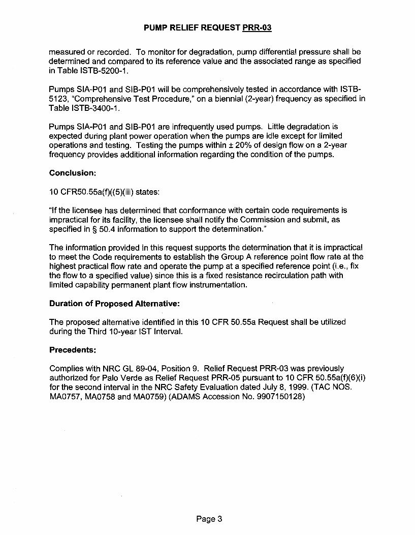
Pumps SIA-P01 and SIB-P01 will be comprehensively tested in accordance with ISTB-5123, "Comprehensive Test Procedure," on a biennial (2-year) frequency as specified inTable ISTB-3400-1.
Pumps SIA-P01 and SIB-P01 are infrequently used pumps. Little degradation isexpected during plant power operation when the pumps are idle except for limitedoperations and testing. Testing the pumps within ± 20% of design flow on a 2-yearfrequency provides additional information regarding the condition of the pumps.
Conclusion:
10 CFR50.55a(f)((5)(iii) states:
"If the licensee has determined that conformance with certain code requirements isimpractical for its facility, the licensee shall notify the Commission and submit, asspecified in § 50.4 information to support the determination."
The information provided in this request supports the determination that it is impracticalto meet the Code requirements to establish the Group A reference point flow rate at thehighest practical flow rate and operate the pump at a specified reference point (i.e., fixthe flow to a specified value) since this is a fixed resistance recirculation path withlimited capability permanent plant flow instrumentation.
Duration of Proposed Alternative:
The proposed alternative identified in this 10 CFR 50.55a Request shall be utilizedduring the Third 10-year IST Interval.
Precedents:
Complies with NRC GL 89-04, Position 9. Relief Request PRR-03 was previouslyauthorized for Palo Verde as Relief Request PRR-05 pursuant to 10 CFR 50.55a(f)(6)(i)for the second interval in the NRC Safety Evaluation dated July 8, 1999. (TAC NOS.MA0757, MA0758 and MA0759) (ADAMS Accession No. 9907150128)
Page 3

PUMP RELIEF REQUEST PRR-04
Relief Request In Accordance with 10 CFR 50.55a(f)(5)(iii)-- Inservice Testing Impracticality -
HPSI Pump Flow Rate Measurement
ASME Components AffectedPump ID Pump Description Code Class Pump Group
SIA-P02 High Pressure Safety Injection 2 B(HPSI) Pump
SIB-P02 High Pressure Safety Injection 2 B(HPSI) Pump
Component/System Function:
The HPSI pumps provide high-pressure coolant injection of borated water into thereactor coolant system under accident conditions. They also provide flow for long-termcooling and flushing to prevent boron precipitation.
Applicable Code Edition and Addenda:
ASME OM Code 2001 Edition w/2003 Addenda
Applicable Code Requirement(s):
ISTB-3300, "Reference Values," ISTB-3300(e)(2), "Reference values shall beestablished within ± 20% of pump design flow for the Group A and Group B tests, ifpracticable. If not practicable, the reference point flow rate shall be established at thehighest practical flow rate."
ISTB-5122, "Group B Test Procedure," "Group B tests shall be conducted with the pumpoperating at a specified reference point. The test parameter value identified in TableISTB-3000-1 shall be determined and recorded as required by this paragraph."
ISTB-5122(b) "The differential pressure or flow rate shall be determined and comparedto its reference value."
Impracticality of Compliance:
The Code requirements to establish the Group B reference point flow rate at the highestpractical flow rate and operate the pump at a specified reference point (i.e., fix the flowto a specified value) is impractical since this is a fixed resistance recirculation path ofapproximately 170 gpm which is measured by limited capability permanent plant flowinstrumentation. The installed instrumentation is a 0-5000 gpm ultrasonic flowmeterwith ± 5% accuracy and does not meet the 2% instrument requirements of TableISTB-3500-1 for pump testing. The use of an ultrasonic flowmeter with 2% accuracywas evaluated and determined to be impractical due to the difficulty in establishing anapplication specific 2% calibration on the SI mini-flow piping. To establish the fixed
Page 1

PUMP RELIEF REQUEST PRR-04
resistance the minimum flow recirculation line contains a flow orifice and a normallyopen motor-operated valve and solenoid isolation valve. Allowing the flow to remainfixed by the orifice resistance increases the potential for repeatable test results anddegradation monitoring rather than attempting to change the resistance based onultrasonic flowmeter readout fluctuations. When the pump operates on minimum flowrecirculation the specified reference point is essentially achieved by the fixed resistance.With this understanding, there is little value added in replacing the existing 0-5000 gpm,± 5% ultrasonic flowmeter, or adding instrumentation that meets IST-351 0requirements. The fixed resistance methodology is repeatable from test to test andaccomplishes the same result as if flow were being measured and recorded.
Burden Caused by Compliance:
During normal plant operation, the HPSI pumps cannot develop sufficient dischargepressure to overcome RCS pressure and allow flow through the safety injectionheaders. Thus, during quarterly testing, HPSI flow is routed through a minimum flowrecirculation line to the refueling water tanks. The minimum-flow recirculation flowpathis a fixed resistance circuit containing a flow-limiting orifice capable of passing only asmall fraction (approx. 170 gpm) of the design flow (815 gpm). The permanent plant 0-5000 gpm, ± 5% accuracy, flow instrumentation (permanently mounted ultrasonicflowmeter) has only limited capability, and its accuracy does not meet TableISTB-3500-1 flow rate 2% accuracy requirements. The use of an ultrasonic flowmeterwith 2% accuracy was evaluated and determined impractical due to the difficulty inestablishing an application specific 2% calibration on the SI mini-flow piping.
The HPSI pumps are categorized as Group B. Pump SIB-P02 is used only occasionallyto recharge the safety injection tanks. Little degradation is expected during plantoperation. Thus, the alternate testing will adequately monitor these pumps to ensurecontinued operability and availability for accident mitigation.
Modifying the minimum flow recirculation line to provide flow indication to meet the ± 2%accuracy requirement as specified in Table ISTB-3500-1 adds little value since the flowis fixed and differential pressure is used to monitor degradation.
Proposed Alternative and Basis for Use:
During plant operation, quarterly Group B pump testing for pumps SIA-P02 and SIB-P02shall be conducted at mini-flow conditions using the minimum flow recirculation linefixed resistance of approximately 170 gpm to establish the specified reference point.ISTB-5100(b)(2) allows the use of bypass test loops to be used for Group B tests. ThePVNGS minimum flow recirculation line is designed to meet the pump manufacturersoperating specifications. The flow rate through the loop is established at the highestpractical flow rate of approximately 170 gpm in accordance with ISTB-3300(e)(2). Flowrate will not be measured or recorded. To monitor for degradation, pump differentialpressure shall be determined and compared to its reference value and the associatedrange as specified in Table ISTB-5100-1.
Page 2
PUMP RELIEF REQUEST PRR-04
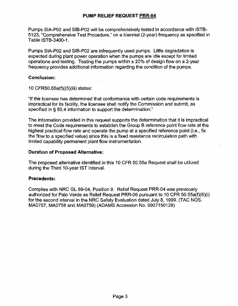
Pumps SIA-P02 and SIB-P02 will be comprehensively tested in accordance with ISTB-5123, "Comprehensive Test Procedure," on a biennial (2-year) frequency as specified inTable ISTB-3400-1.
Pumps SIA-P02 and SIB-P02 are infrequently used pumps. Little degradation isexpected during plant power operation when the pumps are idle except for limitedoperations and testing. Testing the pumps within ± 20% of design flow on a 2-yearfrequency provides additional information regarding the condition of the pumps.
Conclusion:
10 CFR50.55a(f)((5)(iii) states:
"If the licensee has determined that conformance with certain code requirements isimpractical for its facility, the licensee shall notify the Commission and submit, asspecified in § 50.4 information to support the determination."
The information provided in this request supports the determination that it is impracticalto meet the Code requirements to establish the Group B reference point flow rate at thehighest practical flow rate and operate the pump at a specified reference point (i.e., fixthe flow to a specified value) since this is a fixed resistance recirculation path withlimited capability permanent plant flow instrumentation.
Duration of Proposed Alternative:
The proposed alternative identified in this 10 CFR 50.55a Request shall be utilizedduring the Third 10-year IST Interval.
Precedents:
Complies with NRC GL 89-04, Position 9. Relief Request PRR-04 was previouslyauthorized for Palo Verde as Relief Request PRR-06 pursuant to 10 CFR 50.55a(f)(6)(i)for the second interval in the NRC Safety Evaluation dated July 8, 1999. (TAC NOS.MA0757, MA0758 and MA0759) (ADAMS Accession No. 9907150128)
Page 3

PUMP RELIEF REQUEST PRR-05
Relief Request In Accordance with 10 CFR 50.55a(f)(5)(iii)-- Inservice Testing Impracticality -
Containment Spray Pump Flow Rate Measurement
ASME Components AffectedPump ID Pump Description Code Class Pump Group
SIA-P03 Containment Spray (CS) Pump 2 A
SIB-P03 Containment Spray (CS) Pump 2 A
Component/System Function:
CS pumps SIA-P03 and SIB-P03 deliver borated water to the containment sprayheaders, providing containment cooling and pressure control during accident conditions.The CS pumps can also be lined up to provide flow for shutdown cooling.
Applicable Code Edition and Addenda:
ASME OM Code 2001 Edition w/2003 Addenda
Applicable Code Requirement(s):
ISTB-3300, "Reference Values," ISTB-3300(e)(2), "Reference values shall beestablished within ± 20% of pump design flow for the Group A and Group B tests, ifpracticable. If not practicable, the reference point flow rate shall be established at thehighest practical flow rate."
ISTB-5221, "Group A Test Procedure," "Group A tests shall be conducted with the pumpoperating at a specified reference point. The test parameter value identified in TableISTB-3000-1 shall be determined and recorded as required by this paragraph."
ISTB-5221(b), "The resistance of the system shall be varied until the flow rate equalsthe reference point. The differential pressure shall then be determined and compared toits reference value. Alternatively, the flow rate shall be varied until the differentialpressure equals the reference point and the flow rate determined and compared to thereference flow rate value."
ISTB-5221 (c), "Where it is not practical to vary system resistance, flow rate and
pressure shall be determined and compared to their respective reference values."
Impracticality of Compliance:
The Code requires the Group A reference point flow rate to be established at thehighest practical flow rate and operate the pump at a specified reference point (i.e., fixthe flow to a specified value). It is impractical to meet this requirement since this is afixed resistance recirculation path of approximately 190 gpm with limited capabilitypermanent plant flow instrumentation. The installed instrumentation is a 0-5000 gpm
Page 1
PUMP RELIEF REQUEST PRR-05
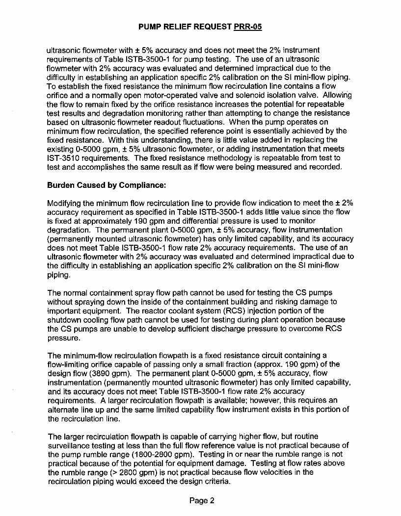
ultrasonic flowmeter with ± 5% accuracy and does not meet the 2% instrumentrequirements of Table ISTB-3500-1 for pump testing. The use of an ultrasonicflowmeter with 2% accuracy was evaluated and determined impractical due to thedifficulty in establishing an application specific 2% calibration on the SI mini-flow piping.To establish the fixed resistance the minimum flow recirculation line contains a floworifice and a normally open motor-operated valve and solenoid isolation valve. Allowingthe flow to remain fixed by the orifice resistance increases the potential for repeatabletest results and degradation monitoring rather than attempting to change the resistancebased on ultrasonic flowmeter readout fluctuations. When the pump operates onminimum flow recirculation, the specified reference point is essentially achieved by thefixed resistance. With this understanding, there is little value added in replacing theexisting 0-5000 gpm, ± 5% ultrasonic flowmeter, or adding instrumentation that meetsIST-3510 requirements. The fixed resistance methodology is repeatable from test totest and accomplishes the same result as if flow were being measured and recorded.
Burden Caused by Compliance:
Modifying the minimum flow recirculation line to provide flow indication to meet the ± 2%accuracy requirement as specified in Table ISTB-3500-1 adds little value since the flowis fixed at approximately 190 gpm and differential pressure is used to monitordegradation. The permanent plant 0-5000 gpm, ± 5% accuracy, flow instrumentation(permanently mounted ultrasonic flowmeter) has only limited capability, and its accuracydoes not meet Table ISTB-3500-1 flow rate 2% accuracy requirements. The use of anultrasonic flowmeter with 2% accuracy was evaluated and determined impractical due tothe difficulty in establishing an application specific 2% calibration on the SI mini-flowpiping.
The normal containment spray flow path cannot be used for testing the CS pumpswithout spraying down the inside of the containment building and risking damage toimportant equipment. The reactor coolant system (RCS) injection portion of theshutdown cooling flow path cannot be used for testing during plant operation becausethe CS pumps are unable to develop sufficient discharge pressure to overcome RCSpressure.
The minimum-flow recirculation flowpath is a fixed resistance circuit containing aflow-limiting orifice capable of passing only a small fraction (approx. 190 gpm) of thedesign flow (3890 gpm). The permanent plant 0-5000 gpm, ± 5% accuracy, flowinstrumentation (permanently mounted ultrasonic flowmeter) has only limited capability,and its accuracy does not meet Table ISTB-3500-1 flow rate 2% accuracyrequirements. A larger recirculation flowpath is available; however, this requires analternate line up and the same limited capability flow instrument exists in this portion ofthe recirculation line.
The larger recirculation flowpath is capable of carrying higher flow, but routinesurveillance testing at less than the full flow reference value is not practical because ofthe pump rumble range (1800-2800 gpm). Testing in or near the rumble range is notpractical because of the potential for equipment damage. Testing at flow rates abovethe rumble range (> 2800 gpm) is not practical because flow velocities in therecirculation piping would exceed the design criteria.
Page 2

PUMP RELIEF REQUEST PRR-05
The CS pumps are categorized as Group A since they are normally used to provideshutdown cooling flow during shutdown operations. Little degradation is expected duringplant operation. Thus, the alternate testing will adequately monitor these pumps toensure continued operability and availability for accident mitigation.
Proposed Alternative and Basis for Use:
During plant operation, quarterly Group A pump testing for pumps SIA-P03 and SIB-P03shall be conducted at mini-flow conditions using the minimum flow recirculation linefixed resistance of approximately 190 gpm to establish the specified reference point.ISTB-5200(b)(1) allows the use of bypass test loops to be used for Group A tests. Theflow rate through the loop is established at the highest practical flow rate ofapproximately 190 gpm in accordance with ISTB-3300(e)(2). Flow rate will not bemeasured or recorded. To monitor for degradation, pump differential pressure shall bedetermined and compared to its reference value and the associated range as specifiedin Table ISTB-5200-1.
Pumps SIA-P03 and SIB-P03 will be comprehensively tested in accordance with ISTB-5223, "Comprehensive Test Procedure," on a biennial (2-year) frequency as specified inTable ISTB-3400-1.
Pumps SIA-P03 and SIB-P03 are infrequently used pumps. Little degradation isexpected during plant power operation when the pumps are idle except for limitedoperations and testing. Testing the pumps within ± 20% of design flow on a 2-yearfrequency provides additional information regarding the condition of the pumps.
Conclusion:
10 CFR50.55a(f)((5)(iii) states:
"If the licensee has determined that conformance with certain code requirements isimpractical for its facility, the licensee shall notify the Commission and submit, asspecified in § 50.4 information to support the determination."
The information provided in this request supports the determination that it is impracticalto meet the Code requirements to establish the Group A reference point flow rate at thehighest practical flow rate and operate the pump at a specified reference point (i.e., fixthe flow to a specified value) since this is a fixed resistance recirculation path withlimited capability permanent plant flow instrumentation.
Duration of Proposed Alternative:
The proposed alternative identified in this 10 CFR 50.55a Request shall be utilizedduring the Third 10-year IST Interval.
Page 3

PUMP RELIEF REQUEST PRR-05
Precedents:
Complies with NRC GL 89-04, Position 9. Relief Request PRR-05 was previouslyauthorized for Palo Verde as Relief Request PRR-1 1 pursuant to 10 CFR 50.55a(f)(6)(i)for the second interval in the NRC Safety Evaluation dated July 8, 1999. (TAC NOS.MA0757, MA0758 and MA0759) (ADAMS Accession No. 9907150128)
Page 4

PUMP RELIEF REQUEST PRR-06
Proposed Alternative In Accordance with 10 CFR 50.55a(a)(3)(ii)-- On the basis that the proposed alternative provides an acceptable level of quality and
safety --Charging Pump Vibration Measurement
ASME Components AffectedPump ID Pump Description Code Class Pump Group
CHA-P01 Charging Pump 2 A
CHB-P01 Charging Pump 2 A
CHE-P01 Charging Pump 2 A
Component/System Function:
The charging pumps provide makeup water to the reactor coolant system for chemistryand volume control. They also provide auxiliary spray to the pressurizer and reactorcoolant pump seal injection.
Applicable Code Edition and Addenda:
ASME OM Code 2001 Edition w/2003 Addenda
Applicable Code Requirement(s):
ISTB-351 0, "General", ISTB-351 0(e), "Frequency Response Range", "The frequencyresponse range of the vibration measuring transducers and their readout system shallbe from one-third minimum pump rotational speed to at least 1000 Hz."
Reason for Request:
The charging pumps are positive-displacement pumps with a constant running speed of199 rpm (equivalent to 3.3 Hz). Compliance with ISTB-3510(e) would require usingvibration instrumentation with a frequency response range of 1.1 Hz to at least 1000 Hz.
A low-speed probe with a frequency response range of 1.6 Hz to 100 Hz was purchasedspecifically for charging pump testing when the IST requirement for frequency responsewas one-half pump speed to at least pump shaft rotational speed. However, this probedoes not meet the lower bound or the upper bound of the current Code-requiredfrequency response range.
The charging pump bearings are oil-lubricated, sleeve type journal bearings. Because ofthe high reciprocating loads, the charging pump bearings are not susceptible to oil whirl,which is the primary failure mode that causes vibration below pump shaft rotationalspeed. There are no other failure mechanisms that manifest themselves with elevatedvibration levels in the range of one-third to one-half pump shaft rotational frequency; allthe remaining failure modes cause vibration at or above the pump speed. Experience
Page 1

PUMP RELIEF REQUEST PRR-06
with these pumps confirms this fact. Therefore vibration instrumentation with afrequency response range above 1.6 Hz is acceptable for monitoring vibration of thecharging pumps.
The low-speed probe is sensitive to vibration frequencies up to 30 times the runningspeed of the charging pumps. This is sufficient to identify bearing degradation,mechanical rubs, and other pump problems producing high-frequency vibrations. Thesepumps are susceptible to degradation mechanisms that would manifest themselves inthe 1.6-100 Hz range and not in the extended vibration range required to be monitoredby the Code (100-1000 Hz). Therefore, use of the higher frequency vibration probeprovides no benefit. The charging pumps are monitored for other symptoms ofdegradation under the PVNGS Predictive Maintenance Program (see PRR-07 for adescription of the PVNGS Predictive Maintenance Program).
Proposed Alternatives and Basis for Use:
The instrumentation used to measure charging pump vibration will have a frequencyresponse range from 1.6 Hz to 100 Hz. Monitoring in the extended vibration rangerequired to be monitored by the Code (100-1000 Hz) provides no benefit.
Conclusion:
10 CFR 50.55a(a)(3) states:
"Proposed alternatives to the requirements of paragraphs (c), (d), (e), (f), (g), and (h) ofthis section or portions thereof may be used when authorized by the Director of theOffice of Nuclear Reactor Regulation. The applicant shall demonstrate that:
(i)The proposed alternatives would provide an acceptable level of quality and safety, or(ii)Compliance with the specified requirements of this section would result in hardship orunusual difficulty without a compensating increase in the level of quality and safety."
The low-speed probe with a frequency response range of 1.6 Hz to 100 Hz discussed inthis relief request provides an acceptable level of quality and safety. Therefore, APSrequests that the proposed alternative be authorized pursuant to 10 CFR50.55a(a)(3)(i).
Duration of Proposed Alternatives:
The proposed alternative identified in this 10 CFR 50.55a Request shall be utilizedduring the Third 10-year IST Interval.
Precedents:
Relief Request PRR-06 was previously authorized for Palo Verde as Relief RequestPRR-07 pursuant to 10 CFR 50.55a(a)(3)(ii) for second interval in the NRC SafetyEvaluation dated July 8,1999. (TAC NOS. MA0757, MA0758 and MA0759) (ADAMSAccession No. 9907150128)
Page 2

PUMP RELIEF REQUEST PRR-07
Proposed Alternative In Accordance with 10 CFR 50.55a(a)(3)(i)-- On the basis that the proposed alternative provides an acceptable level of quality and
safety --
Smooth Running Pumps
ASME Components Affected:Pump ID
AFA-P01
AFB-P01
CTA-P01
CTB-P01
ECA-P01
ECB-P01
EWA-P01
EWB-P01
PCA-P01
PCB-P01
SIA-P01
SIB-P01
SIA-P02
SIB-P02
SIA-P03
SIB-P03
Pump Description Code Class Pump Group
Essential Auxiliary FeedwaterPump (Turbine Driven)
Essential Auxiliary FeedwaterPump (Motor Driven)
Condensate Transfer Pump
Condensate Transfer Pump
Essential Chilled WaterCirculation Pump
Essential Chilled Water
Circulation Pump
Essential Cooling Water Pump
Essential Cooling Water Pump
Spent Fuel Pool Cooling Pump
Spent Fuel Pool Cooling Pump
Low Pressure Safety Injection(LPSI) Pump
Low Pressure Safety Injection(LPSI) Pump
High Pressure Safety Injection(HPSI) Pump
High Pressure Safety Injection(HPSI) Pump
Containment Spray Pump
Containment Spray Pump
Page 1

PUMP RELIEF REQUEST PRR-07
SPA-P01 Essential Spray Pond Pump 3 A
SPB-P01 Essential Spray Pond Pump 3 A
Component/System Function:
Various
Applicable Code Edition and Addenda:
ASME OM Code 2001 Edition w/2003 Addenda
Applicable Code Requirement(s):
ISTB-3300, "Reference Values," Reference values shall be obtained as follows: (a)Initial reference values shall be determined from the results of testing meeting therequirements of ISTB-31 00, Preservice Testing, or from the results of the first inservicetest.
ISTB-3300(f), "All subsequent test results shall be compared to these initial referencevalues or to new reference values established in accordance with ISTB-331 0, ISTB-3320, or ISTB-6200(c)."
ISTB-6200(a), "Alert Range", "If the measured test parameter values fall within the alertrange of Table ISTB-51 00-1, Table ISTB-5200-1, Table ISTB-5300-1, or Table ISTB-5300-2, as applicable, the frequency of testing specified in ISTB-3400 shall be doubleduntil the cause of the deviation is determined and the condition is corrected."
ISTB-6200(b), "Action Range", "If the measured test parameter values fall within therequired action range of Table ISTB-5100-1, Table ISTB-5200-1, Table ISTB-5300-1, orTable ISTB-5300-2, as applicable, the pump shall be declared inoperable until either thecause of the deviation has been determined and the condition is corrected, or ananalysis of the pump is performed and new reference values are established inaccordance with ISTB-6200(c)."
Reason for Request:
Palo Verde has several pumps with vibration parameters readings in the range of_•0.05 ips. Vibration velocities in this range can be significantly affected by hydraulic
flow noise and repeatability of the vibration instruments. As a result, Palo Verde couldbe required to increase the frequency of specified testing when no degradation of themonitored equipment exists.
PVNGS expends considerable resources on preventive and predictive maintenance.One result of these efforts is a number of pumps run very smoothly. For example, manypumps in the PVNGS IST Program would currently be candidates for "smooth-running"status under PRR-07, as shown in the table below. To impose Code-mandated Alertand Required Action values on "smooth-running" pumps unnecessarily penalizesPVNGS for achieving this high level of performance.
Page 2

PUMP RELIEF REQUEST PRR-07
Typical Vibration
Reference Values inch
Pump per second (ips)
Auxiliary Feedwater 0.12 - 0.27Condensate Transfer * 0.0044 - 0.0883Essential Chilled Water * 0.0075 - 0.0597Essential Cooling Water * 0.0295 - 0.0931Low Pressure Safety Injection * 0.0343 - 0.174High Pressure Safety Injection 0.0667 - 0.296Containment Spray 0.078 - 0.161Spent Fuel Pool Cooling * 0.031 -0.110Essential Spray Pond * 0.0201 - 0.0864
* Candidates for "smooth-running" status under PRR-007
For displacement reference values less than 0.5 mils, it is noted that the Section XICode in effect for the first interval of the IST Program (1980 Edition, Winter 1981Addenda) sets the Alert Range at > 1.0 mil and the Required Action Range at > 1.5 mil.This implies a minimum reference value of 0.5 mils, which is equivalent to 0.047 ips for1800 rpm pumps and 0.094 ips for 3600 rpm pumps. The effective reference valuesproposed for smooth-running pumps are roughly equal to the implied Section XIreference values for 1800 rpm pumps and more conservative than the implied referencevalues for 3600 rpm pumps. Without proposed alternative, the Alert Ranges for severalsmooth running pumps will be reduced by a factor of 10.
Proposed Alternatives and Basis for Use:
Vibration parameters that have reference values < 0.05 ips are considered "smooth-running". When vibration velocities are less than 0.05 ips, changes have been shown tobe non-significant. To reduce any unnecessary penalty for those pump parametersconsidered "smooth-running", the Alert and Required Action values for these "smooth-running" parameters will be determined as if their reference value is 0.05 ips; that is, theAlert Range will be 0.125 ips to 0.3 ips, and the Required Action Range will be > 0.3 ips.Candidates for "smooth-running" status will be analyzed per ISTB-3300(g) and ISTB-6400 to verify that use of this relief request will not prevent the detection of significantpump degradation. If any of these parameters are outside normally expected ranges,an evaluation will be performed and appropriate corrective actions will be taken.
The basis for use of these proposed Alert and Required Action ranges is discussedbelow.
In addition to the Code-mandated monitoring, these pumps are monitored under thePVNGS Predictive Maintenance Program. This program includes the following:
* Spectrum band monitoring* Bearing acceleration monitoring (on ball and roller bearings only)* Bearing oil analysis (for oil lubricated bearings)
Page 3

VALVE RELIEF REQUEST VRR 01
* OMN-1, R 0, 3.4, Effect of MOV Replacement, Repair, or Maintenance, states thatwhen an MOV or its control system is replaced, repaired, or undergoes maintenancethat could affect the valve's performance, new inservice test values shall bedetermined or the previously established inservice test values shall be confirmedbefore the MOV is returned to service.
Diagnostic test results within the MOV Program setpoint bands are considered to besatisfactory and do not require analysis.
" OMN-1, R 0, 3.5, Grouping of MOVs for Inservice Testing, states that groupingMOVs for inservice testing is permissible.
PVNGS currently has elected not to use Grouping of MOVs for Inservice Testing.
* OMN-1, R 0, 3.7, Risk Basis Criteria for MOV Testing, states that if establishing riskbased criteria for performance testing, the Owner shall consider the following:(a) develop an acceptable basis for MOV risk determination;(b) develop MOV screening criteria to determine each MOV's contribution to risk;
and(c) establish applicability by a documented evaluation from a plant expert panel.
Palo Verde is currently not planning to implement a Risk Informed Program for itsIST program. As noted above, Palo Verde uses risk/safety significance and MOVmargin as part of the JOG program to establish MOV testing frequency. Thisprovision is not applicable.
OMN-1, R 0, 6.3, Evaluation of Data, and 6.4, Determination of MOV FunctionalMargin, state that the owner shall determine which methods are suitable forevaluating test data for each MOV and application and that the owner shalldemonstrate that adequate margin exists between the required torque and availabletorque and that changes to the operating characteristics of the MOV do not result inreaching a point of insufficient margin before the next schedule test activity.
Palo Verde utilizes the JOG Program criteria for determining MOV test frequency.The MOV test frequencies have been established to ensure MOV setpoints andMOV margins are maintained over the MOV test interval which satisfies thisrequirement of OMN-1, R 0,.
OMN-1, R 0, 6.4.1, Determination of Required Torque, states that design basisrequired torque shall be determined from measurements taken during testing atdesign basis conditions.
Palo Verde determines a Stem Factor for rising stem valves whenever stem thrustand stem torque are measured. However, it is not possible to measure thrust andtorque on all rising stem valves.
Page 4

PUMP RELIEF REQUEST PRR-07
0 Motor Current Signature analysis (for all but the smallest motors)
The PVNGS Predictive Maintenance (PdM) Program is part of the PreventiveMaintenance (PM) Program described in UFSAR Section 17.2.3.11.1.6. The PMProgram was developed using RCM, EPRI, and INPO guidelines as well as factoring inPVNGS site-specific experience and regulatory requirements. The PM Program andPdM activities are controlled by plant procedures. Each of these pumps has amaintenance plan documented in the PM Program which describes the PM and PdMactivities performed on that pump. The performance of the system associated witheach of these pumps is monitored and compared to performance criteria under thePVNGS Maintenance Rule Program. This ensures the continued effectiveness of thePM program to minimize component failures and maintain or improve systemperformance (balance availability and reliability).
The PVNGS Predictive Maintenance Program uses vibration analysis, lubricantanalysis, and infrared thermographic analysis as appropriate, to predict the need formaintenance so that equipment can be worked prior to failure. The componentsincluded in this program include those considered important to safe and reliable plantoperation, including certain pumps in the IST Program. The intervals for monitoring arebased on manufacturer's recommendations, maintenance history, cost effectiveness,and experience. Although parts of the monitoring, analysis, database, and softwareused in the Predictive Maintenance Program do not fall under the PVNGS QualityProgram, the Predictive Maintenance Program still provides valuable information forassuring the operational readiness of smooth-running pumps.
The vibration analysis program monitors the vibration of rotating machinery. In additionto the vibration at pump bearings, the vibration of the driver (turbine or motor) bearingsare also collected and trended. Analyzed parameters and methods include vibrationvelocity, bearing acceleration, bearing high frequency detection, and spectral analysis.
The lubricant analysis program samples lubricants and analyzes them to identifydegradation or negative trends. Most testing is performed at the on-site lubricationlaboratory, where capabilities include wear debris, chemical composition, andlubrication cleanliness analysis.
In both the vibration monitoring and lubricant analysis programs, recently acquired datais compared with previous data to detect any indicated degradation of equipmentcondition. If degradation indicates the reliability of operating equipment may benegatively affected, or if acceptance criteria are no longer being met, appropriatecorrective action is taken. Corrective action may include: continuing trending of thedegraded condition, if the condition is not considered to be immediately threatening tothe equipment and can be corrected during a time window convenient to plantoperation; additional testing or monitoring to confirm the suspected degraded condition;inspection and repair of the equipment as necessary; changes to preventivemaintenance procedures or schedules; or design changes.
Page 4

PUMP RELIEF REQUEST PRR-07
The following table contains examples of Unit I vibration test result historydemonstrates consistent smooth running operation (Unit 2 and 3 are similar):
Unit Pump Date Pump Pump AxialHorizontal Vertical
1 CTAP01 7/2/2006 .016 .012 .0061 CTAP01 9/18/2006 .020 .012 .00791 CTAP01 12/11/2006 .021 .014 .0071 CTAP01 3/8/2007 .019 .012 .0058
1 CTBP01 11/8/2006 .024 .007 .00821 CTBPO1 12/7/2006 .014 .007 .00951 CTBPO1 1/29/2007 .016 .006 .0111 CTBPO1 4/25/2007 .017 .007 .009
1 ECAP01 8/22/2006 .036 .034 .0101 ECAP01 11/13/2006 .044 .027 .00921 ECAP01 2/5/2007 .057 .057 .00811 ECAP01 5/1/2007 .042 .034 .007
1 ECBPO1 8/8/2006 .026 .021 .0131 ECBPO1 10/31/2006 .028 .024 .0161 ECBPO1 1/22/2007 .030 .026 .0121 ECBPO1 4/16/2007 .023 .027 .012
1 EWAP01 8/22/2006 .031 .028 .0201 EWAP01 11/13/2006 .032 .023 .02141 EWAP01 2/6/2007 .033 .031 .01821 EWAP01 5/3/2007 .032 .034 .023
1 EWBPO1 8/8/2006 .033 .034 .0261 EWBP01 10/31/2006 .033 .032 .0261 EWBP01 1/23/2007 .033 .031 .0231 EWBPO1 4/17/2007 .035 .038 .027
1 SIAP01(b) 4/11/2004 .033 .048 (a)1 SIAP01(D) 11/29/2005 .047 .053 (a)1 SIAP01(b) 12/8/2005 .043 .061 (a)1 SIAP01(b) 6/1/2006 .057 .071 (a)
1 SIBP01 (b) 10/4/2002 .031 .032 (a)1 SlBP01(b) 4/23/2004 .044 .060 (a)1 SIBPO1(b) 10/16/2005 .027 .035 (a)1 SIBPO1(b) 5/29/2006 .041 .062 (a)
1 PCAP01 6/28/2006 .060 .040 .0241 PCAP01 9/26/2006 .059 .036 .0271 PCAP01 12/11/2006 .058 .038 .0291 PCAP01 3/6/2007 .058 .037 .023
1 PCBPO1 6/20/2006 .077 .037 .0231 PCBPO1 9/11/2006 .075 .041 .0251 PCBPO1 12/4/2006 .072 .045 .026
Page 5

PUMP RELIEF REQUEST PRR-07
Unit Pump Date Pump Pump AxialHorizontal Vertical
1 PCBP01 2/26/2007 .071 .041 .021
1 SPAP01(b) 8/22/2006 .049 .027 .02751 SPAP01(b) 11/14/2006 .052 .023 .02701 SPAP01(b) 2/6/2007 .055 .027 .02501 SPAP01(b) 5/3/2007 .049 .027 .0283
1 SPBP01(b) 8/7/2006 .092 .047 .02611 SPBP01(b) 11/1/2006 .088 .027 .02401 SPBP01(b) 1/23/2007 .090 .030 .0291 SPBP01(b) 4/19/2007 .088 .035 .026
(a) - Inaccessible (b) - vibration readings taken at the motor-
Conclusion:
10 CFR 50.55a(a)(3) states:
"Proposed alternatives to the requirements of paragraphs (c), (d), (e), (f), (g), and (h) ofthis section or portions thereof may be used when authorized by the Director of theOffice of Nuclear Reactor Regulation. The applicant shall demonstrate that:
(i)The proposed alternatives would provide an acceptable level of quality and safety, or(ii)Compliance with the specified requirements of this section would result in hardship orunusual difficulty without a compensating increase in the level of quality and safety."
The revised Alert and Required Action values discussed in this relief request providesan acceptable level of quality and safety. Therefore, APS requests that the proposedalternative be authorized pursuant to 10 CFR 50.55a(a)(3)(i).
Duration of Proposed Alternatives:
The proposed alternative identified in this 10 CFR 50.55a Request shall be utilizedduring the Third 10-year IST Interval.
Precedents:
Relief Request PRR-07 was previously authorized for Palo Verde as Relief RequestPRR-08 pursuant to 10 CFR 50.55a(a)(3)(i) for the second interval in the NRC SafetyEvaluation dated July 8,1999. (TAC NOS. MA0757, MA0758 and MA0759) (ADAMSAccession No. 9907150128)
Page 6

VALVE RELIEF REQUEST VRR 01
Proposed Alternative In Accordance with 10 CFR 50.55a(a)(3)(i)On the basis that the proposed alternative provides an acceptable level
of quality and safety.
Code Case OMN-1 - MOV Exercising and Stroke Timing
Component(s) Affected:
Motor-operated valve assemblies currently included in the Palo Verde NuclearGenerating Station (PVNGS) Motor-Operated Valve (MOV) Program
Component/System Function: Various
Applicable Code Edition and Addenda:
ASME OM Code 2001 Edition w/2003 Addenda
Applicable Code Requirement(s):
ISTA-3130, "Application of Codes Cases," paragraph (b) states that Code Cases shallbe applicable to the edition and addenda specified in the test plan.
ISTC-3500, "Valve Testing Requirements," states that active and passive valves in thecategories defined in ISTC-1 300 shall be tested in accordance with the paragraphsspecified in Table ISTC-3500-1 and the applicable requirements of ISTC-5100 andISTC-5200.
ISTC-3700, "Position Verification Testing," states that valves with remote positionindicators shall be observed locally at least once every 2 years to verify the valveoperation is accurately indicated.
ISTC-5120, "Motor-Operated Valves," paragraph states that active valves shall havetheir stroke times measured when exercised in accordance with ISTC-3500.
Reason for Request:
Code Case OMN-1, Revision 0 provides alternative rules to those of OM Code,Subsection ISTC, for preservice and inservice testing to assess the operationalreadiness of certain electric motor-operated valve assemblies in light-water reactorpower plants. However, Regulatory Guide (RG) 1.192 has not yet extended its use tothe 2001 Edition w/2003 Addenda of the OM Code which is the basis for the plannedthird 10-year IST program at Palo Verde.
Proposed Alternatives and Basis for Use:
In lieu of the provisions for MOV testing in Subsection ISTC of the 2001 Edition w/2003Addenda of the ASME OM Code, APS requests relief for the continued use of ASMECode Case OMN-1, Revision 0.
Page 1

VALVE RELIEF REQUEST VRR 01
Pursuant to ASME Code Case OMN-1, Revision 0 and the guidelines provided inNUREG-1482, Revision 1, Section 4.2.5, PVNGS proposes to continue implementationof Code Case OMN-1 in lieu of the stroke-time provisions specified in ISTC-5120 forMOVs. Code Case OMN-1 has been determined by the NRC to provide an acceptablelevel of quality and safety when implemented in conjunction with the conditions imposedin RG 1.192.
The conditions specified in RG 1.192 are as follows:
Regulatory Guide 1.192, Operation and Maintenance Code Case Acceptability, ASMEOM Code, dated June 2003 states that licensees may use Code Case OMN-1,"Alternative Rules for Preservice and Inservice Testing of Certain ElectricMotor-Operated Valve Assemblies in Light-Water Reactor Power Plants," Revision 0, inlieu of the provisions for stroke-time testing in Subsection ISTC of the 1995 Edition up toand including the 2000 Addenda of the ASME OM Code when applied in conjunctionwith the provisions for leakage rate testing in, as applicable, ISTC 4.3 (1995 Edition withthe 1996 and 1997 Addenda) and ISTC-3600 (1998 Edition with the 1999 and 2000Addenda). In addition, licensees who continue to implement Section Xl of the ASMEBPV Code as their Code of Record may use OMN-1 in lieu of the provisions for stroke-time testing specified in Paragraph 4.2.1 of ASME/ANSI OM Part 10 as required by 10CFR 50.55a(b)(2)(vii) subject to the conditions in this Regulatory Guide (RG) 1.192.Licensees who choose to apply OMN-1 are required to apply all its provisions.
The relevant provisions are as follows:
(1) The adequacy of the diagnostic test interval for each motor-operated valve (MOV)must be evaluated and adjusted as necessary, but not later than 5 years or threerefueling outages (whichever is longer) from initial implementation of OMN-1.
(2) When extending exercise test intervals for high risk MOVs beyond a quarterlyfrequency, licensees must ensure that the potential increase in Core DamageFrequency (CDF) and risk associated with the extension is small and consistent withthe intent of the Commission's Safety Goal Policy Statement.
(3) When applying risk insights as part of the implementation of OMN-1, licensees mustcategorize MOVs according to their safety significance using the methodologydescribed in Code Case OMN-3, "Requirements for Safety SignificanceCategorization of Components Using Risk Insights for Inservice Testing of LWRPower Plants," with the conditions discussed in RG 1.192 or use other MOV riskranking methodologies accepted by the NRC on a plant specific or industry-widebasis with the conditions in the applicable safety evaluations.
In addition, the following implementation clarifications are necessary:
* OMN-1, R 0, 3.1, Design Basis Verification Test, states that justifications for testingat conditions other than design bases conditions and for grouping like MOVs shall bedocumented by an engineering evaluation, alternative testing techniques, or both.
Page 2
VALVE RELIEF REQUEST VRR 01
Design Basis Verification Testing was completed during plant startup testing and inresponse to NRC Generic Letter (GL) 89-10 testing requirements, which satisfies therequirement of OMN-1.
* OMN-1, R 0, 3.2, Preservice Test, states that each MOV shall be tested during thepreservice test period or before implementing inservice testing.
Preservice Testing was performed pursuant to NRC GL 89-10 testing requirements,which meet the intent of this requirement.
* OMN-1, R 0, 3.3 (b), Inservice Test, states that inservice tests shall be conducted inthe as-found condition.
Because of the extensive PVNGS MOV performance history, some as-found MOVtesting can be waived by a documented engineering evaluation, e.g., if amodification to the valve or actuator will be performed or if valve maintenance isplanned (such as valve repacking) and for activities that will require a postmaintenance diagnostic test to return the MOV to service. This provision will notapply if there is reason to suspect the MOV is not operating properly prior to themaintenance activity.
OMN-1, R 0, 3.3 (c), Inservice Test, states that the inservice testing program will
include a mix of static and dynamic MOV performance testing.
Dynamic testing will be performed to address MOV modifications.
PVNGS performed differential pressure testing in accordance with NRC GL 89-10and also participated in the Joint Owners Group (JOG) differential pressure testingprogram (i.e., dynamic testing) which has been completed. The mix of static anddynamic testing at PVNGS in the future will be static testing with additional dynamictesting performed as required by the PVNGS MOV Program to address MOVmodifications.
OMN-1, R 0, 3.3.1, Inservice Test Frequency, states that the inservice testfrequency shall be determined in accordance with 6.4.4 or that testing shall beconducted every 2 refueling cycles or 3 years (whichever is longer) until sufficientdata exist to determine a more appropriate test frequency not to exceed 10 years.
Palo Verde has committed to the JOG program as part of its response to NRC GL96-05. Inservice Test Intervals will be established based on MOV margin and thevalve's risk/safety significance in accordance with JOG program requirements.PVNGS is currently implementing the JOG Interim Test Program in accordance withJOG Report MPR 1807. PVNGS will implement the final JOG Periodic VerificationProgram in accordance with JOG Report MPR 2524-A as noted in the NRC SER onthe JOG program.
Page 3

VALVE RELIEF REQUEST VRR 01
" OMN-1, R 0, 6.4.2.1, Available Output Based on Motor Capabilities and 6.4.2.2,Available Output Based on Torque Switch Setting, states that stem torque shall bedetermined.
Palo Verde actuator output capabilities are determined as an integral part of theMOV design basis calculations and are not performed as part of the evaluation ofMOV test data. The evaluation of test data compares actuator output to theacceptance band determined in design basis calculations. This applies to allactuators and includes those actuators setup based on limit switches.
For actuators setup based on torque switches, available output includes torquemeasurement uncertainty (or displacement uncertainty if springpack displacement isused) and torque switch repeatability.
" OMN-1, R 0, 6.4.3, Calculation of MOV Functional Margin, states that MOVfunctional margin shall be calculated as the difference between the available stemtorque and the required stem torque.
Palo Verde calculates the margin as a percentage (vice difference in thrust or torquebetween available output and valve operating requirements).
" OMN-1, R 0, 6.4.4, Determination of MOV Test Interval, states that calculations fordetermining MOV functional margin shall also be evaluated to account foranticipated time-related changes in performance.
As noted above for OMN-1, R 0, 3.3.1, the test interval is based on the NRCapproved JOG program.
" OMN-1, R 0, 9.1, Test Information, states that test information shall be recorded orverified for MOV testing described in Section 3 and provides information that shouldbe considered.
Test Information relevant to the MOV being tested and relevant test parameters willbe recorded electronically with the test trace and/or on the test data sheet. MOVconfiguration data not directly related to testing, e.g., name plate information,breaker setting, etc. are maintained in plant records.
Code Case OMN-1, R 0, should be considered acceptable for use with OM Code-2001Edition w/2003 Addenda as the Code of record. Therefore, pursuant to 10 CFR50.55a(a)(3)(i), PVNGS requests relief from the specific ISTC Code requirementsidentified in this relief request.
Conclusion:
10 CFR 50.55a(a)(3) states:
"Proposed alternatives to the requirements of paragraphs (c), (d), (e), (f), (g), and (h) ofthis section or portions thereof may be used when authorized by the Director of theOffice of Nuclear Reactor Regulation. The applicant shall demonstrate that:
Page 5
VALVE RELIEF REQUEST VRR 01
(i)The proposed alternatives would provide an acceptable level of quality and safety, or(ii)Compliance with the specified requirements of this section would result in hardship orunusual difficulty without a compensating increase in the level of quality and safety."
The continued use of ASME Code Case OMN-1, Revision 0, as discussed in this reliefrequest provides an acceptable level of quality and safety. Therefore, APS requeststhat the proposed alternative be authorized pursuant to 10 CFR 50.55a(a)(3)(i).
Duration of Proposed Alternatives:
The proposed alternative identified in this relief request shall be utilized during the third10-year IST interval.
Precedents:
Relief Request VRR-01 was previously authorized for Palo Verde as Relief RequestVRR-1 2 pursuant to 10 CFR 50.55a(a)(3)(i) for second interval in the NRC SafetyEvaluation dated July 8,1999. (TAC NOS. MA0757, MA0758 and MA0759) (ADAMSAccession No. 9907150128)
References:
NUREG-1482, Revision 1, Section 4.2.5, "Alternatives to Stroke-Time Testing"
Regulatory Guide 1.192, "Operation and Maintenance Code Case Acceptability, ASMEOM Code", Table 2, "Conditionally Acceptable OM Code Cases"
OM Code-2001 Edition w/2003 Addenda, Paragraph ISTC-5120, "Motor OperatedValves"
OM Code-2001 Edition w/2003 Addenda, Paragraph ISTA-3130, "Application of CodeCases"
Code Case OMN-1, Revision 0, "Alternative Rules for Preservice and Inservice Testingof Certain Electric Motor-Operated Valve Assemblies in LWR Power Plants"
Page 6

ENCLOSURE 2
Information Copy of the Revised Third 10-Year Interval Pumpand Valve Inservice Testing Program

NUCLEAR ADMINISTRATIVE AND TECHNICAL MANUAL Page 1 of 100
PUMP AND VALVE INSERVICE TESTING PROGRAM 73DP-9XI01 Revision
AND COMPONENT TABLES 21
Procedure Intent
This procedure identifies the pump and valve tests performed to meet the requirements of 10CFR 50.55a, ASME/ANSI OM Code 2001 Edition w/2003 Addenda, and TechnicalSpecification 5.5.8 for the Third 10-Year IST Interval.
Revision 20 Changes
* This revision represents a total re-write to reflect the requirements for the Third 10-YearIST Interval, effective 1/15/2008 through 1/14/2018.

NUCLEAR ADMINISTRATIVE AND TECHNICAL MANUAL Page 2 of 100
PUMP AND VALVE INSERVICE TESTING PROGRAM 73DP-9XI01 Revision
AND COMPONENT TABLES 21
Table of Contents
Section Page
1.0 Program Purpose .................................................................. 3
2.0 R egulatory B asis .................................................................. 4
3.0 OM Code Case Acceptability ................................................. 6
4.0 Program Development .......................................... 8
5.0 Component Tables ................................................................ 9
6.0 References ......................................................................... 9
Component Table - Pumps .............................................................. 10
Component Table - Valves .............................................................. 12
Code Deviation Index ..................................................................... 50
Pump 1OCFR50.55a Requests .............................................................. 51
Valve Cold Shutdown Justifications ....................................................... 78
Valve Refueling Outage Justifications ..................................................... 88
Valve 1 OCFR50.55a Requests ............................................................... 90
Notes, Legends, Definitions and Abbreviations ........................................... 95

NUCLEAR ADMINISTRATIVE AND TECHNICAL MANUAL Page 3 of 100
PUMP AND VALVE INSERVICE TESTING PROGRAM 73DP-9XI01 Revision
AND COMPONENT TABLES 21
1.0 PROGRAM PURPOSE
Third 10-Year Interval IST Program Update.
This procedure identifies the pump and valve tests performed to meet the requirements of10 CFR 50.55a, ASME/ANSI OM Code 2001 Edition w/2003 Addenda, and TechnicalSpecification 5.5.8.
This program is applicable to PVNGS Units 1, 2, and 3. The pumps and valves withinthe scope of this program are identified in the component tables.
This program plan document provides the requirements for assessing the operationalreadiness of pumps and valves whose specific functions are required to bring the reactorfrom any operating mode to the safe shutdown condition, in maintaining the safeshutdown condition, or in mitigating the consequences of an accident.
Palo Verde Nuclear Generating Station is licensed with a safe shutdown condition ofCold Shutdown.
The Inservice Testing Program for Pumps and Valves is applicable for a one hundredtwenty (120) month interval. The chronology for Palo Verde Nuclear Generating Stationis listed below:
In 1995, PVNGS changed the 120-month intervals for the Unit 1, 2, and 3 ISTprograms in order to establish concurrent intervals. The change revised the enddates of the initial 120-month intervals and the start dates of the second 120-month intervals of all three units to a common date of January 15, 1997. Theoriginal schedules were based on the commercial operation dates of the units.This change was made to provide greater consistency between units and tosimplify the 120-month updates required by 10 CFR 50.55a(f)(4)(ii).
" In 1997, the NRC granted a 1-Year Interval extension (to January 15, 1998) for allthree units.
1. The first 120-month interval for Unit 1 began on 1/28/1986, the commercialoperating date, through 01 / 15/1998.
2. The first 120-month interval for Unit 2 began on 9/22/1986, the commercialoperating date, through 01/15/1998.
3. The first 120-month interval for Unit 3 began on 1/08/1988, the commercialoperating date, through 01/15/1998.
" The second 120-month interval IST Program for all three units began on,01/15/1998 and ends on 01/14/2008.

NUCLEAR ADMINISTRATIVE AND TECHNICAL MANUAL Page 4 of 100
PUMP AND VALVE INSERVICE TESTING PROGRAM 73DP-9XI01 Revision
AND COMPONENT TABLES 21
* The third 120-month interval IST Program for all three units begins on01/15/2008 and ends on 01/14/2018.
The IST Program is submitted to the NRC for their overall review and specific approvalof associated 1 OCFR50.55a Requests for the successive 120-month IST Program. Theprogram documents submitted to the NRC are used to prepare for IST inspections and toreview 1OCFR50.55a Requests.
Regarding periodic changes, NUREG 1482, Revision 1, Section 2.6, "ProgramDocuments," specifies that between a licensee's 10-year interval program submittal, theNRC would like to receive up-to-date program documents when the licensee makessignificant changes to the IST program to facilitate these regulatory activities. As long asthe IST program is consistent with the regulations, ASME Code relief is not required.That is, deletions from or additions to the'IST program do not necessarily require NRCapproval. The burden is on each licensee to verify that its IST program is complete andincludes all components that require IST, and that all such components are tested to theextent practical. If a licensee deletes a particular component from its IST program, thestaff recommends that the licensee should document the reason in an appropriate place.The staff expects each licensee to maintain its IST program up-to-date and ensure that itremains consistent with changes in plant configuration. If a particular relief request is nolonger required because of changes in hardware, system design, or new technology, thelicensee is expected to revise its program to withdraw the relief request. Conversely, if asystem modification results in the addition of a component to the IST program, thelicensee should ensure that it meets the Code requirements or the provisions of GL 89-04,or that a relief request is submitted for NRC review and approval, as appropriate.
This program plan document establishes the requirements which have been translatedinto implementing (surveillance) procedures for inservice testing and evaluation of Class1, 2, and 3 pumps and valves. Additionally, using the guidance in NUREG 1482,Revision 1, certain other pumps and valves not required to be classified as Class 1, 2, and3, but which perform a specific function required to bring the reactor from any operatingmode to the safe shutdown condition, in maintaining the safe shutdown condition, or inmitigating the consequences of an accident, are also included.
2.0 REGULATORY BASIS
Code of Federal Regulations, Title 10, Section 50.55a (1OCFR50.55a), "Codes andStandards," states requirements for IST of certain safety-related pumps and valves.These components are required to be tested according to the requirements of Operationand Maintenance of Nuclear Power Plants, ASME OM Code-2001 Edition through the2003 Addenda. The testing is intended to assess operational readiness of components.The tests conducted during the initial and successive 120-month intervals are to be basedon the requirements in the applicable edition and addenda of the Code, to the extent

NUCLEAR ADMINISTRATIVE AND TECHNICAL MANUAL Page 5 of 100
PUMP AND VALVE INSERVICE TESTING PROGRAM 73DP-9XI01 Revision
AND COMPONENT TABLES 21
practical, within the limitations of design, geometry, and materials of construction, as.described in 10 CFR50.55a(f)(4).
10 CFR50.55a(f)(4)(ii) requires that IST in each 120-month interval following the initialinterval be conducted in compliance with the requirements of the latest edition andaddenda of the Code incorporated by reference in lOCFR50.55a(b), in effect 12 monthsbefore the start of the interval. Pursuant to 1OCFR50.55a(f)(4)(iv), IST may meet therequirements of subsequent editions and addenda incorporated by paragraph (b) orportions of a revised edition. When portions of a revised edition are used, all relatedrequirements of the respective editions or addenda must be met and approval of the NRCobtained as clarified by RIS-04-012 dated 7/28/2004.
The NRC may authorize alternatives to Code testing requirements submitted as1OCFR50.55a requests, or submitted in a similar format that includes a description of therequirements, a description of the proposed alternative, and the justification for approvalof the alternative. 1OCFR50.55a(a)(3)(i) allows the NRC to authorize alternatives if theproposed alternatives would provide an acceptable level of quality and safety. The NRCwill normally approve an alternative pursuant to this provision only if the licenseeproposes a method of testing that is an equivalent method, or an improvement, to theCode method, or if the testing will comply or is consistent with the later Code editionsapproved by NRC in 1 OCFR50.55a(b). Where plant design makes the testing of certaincomponents complicated or impossible, an alternate method of testing is documented in a1 OCFR50.55a Request.
The Palo Verde Nuclear Generating Station (PVNGS) Inservice Testing Program forPumps and Valves was developed in accordance with the requirements of ASME OMCode-2001, (Subsections ISTA, ISTB, ISTC, Mandatory Appendix I and MandatoryAppendix II) including subsequent changes in the ASME OMb Code-2003 Addenda.
The components were classified and categorized in accordance with the Code of Recordwith test requirements and intervals assigned accordingly. Technical Specification,UFSAR and other licensing commitments were referenced during the assignment of testintervals. Additional guidance for the development of the PVNGS Inservice TestingProgram was obtained from NUREG 1482, Revision 1, "Guidelines for Inservice Testingat Nuclear Power Plants."
The 1 OCFR50 Appendix J Program for Primary Containment Testing at Palo VerdeNuclear Generating Station is in compliance with the requirements of Option B ofIOCFR50 Appendix J, Regulatory Guide 1.163, September 1995, NEI 94-01 Revision 0,July 1995 and Station Technical Specifications.

NUCLEAR ADMINISTRATIVE AND TECHNICAL MANUAL Page 6 of 100
PUMP AND VALVE INSERVICE TESTING PROGRAM 73DP-9XI01 Revision
AND COMPONENT TABLES 21
3.0 OM CODE CASE ACCEPTABILITY
3.1 ISTA-3130 Application of Code Cases
(a) Code Cases to be used during a preservice or inservice test or examinationshall be identified in the test plan.
(b) Code Cases shall be applicable to the edition and addenda specified in thetest plan.
(c) Code Cases shall be in effect at the time the test plan is filed, except asprovided in ISTA-3130(d).
(d) Code Cases issued subsequent to filing the test plan may be proposed foruse in amendments to the test plan.
3.2 NUREG 1482, Revision 1, Section 2.1.1, ASME Code Case Applicability
If a licensee would like to use an ASME Code Case with a Edition or Addendumof the ASME Code to which it is not applicable, the licensee has the followingoptions:
a. Have the alternative to use the Code Case, beyond its stated applicability,authorized by the NRC pursuant to 1 OCFR50.55a(a)(3),
OR
b. If the Code Case is applicable to an Edition or Addendum of the ASME Codelater than the version of the Code being used by the licensee, the licenseecould update to the later version of the Code pursuant tolOCFR50.55a(f)(4)(iv) or (g)(4)(iv) and then use the Code Case, provided theCode Case has been approved for use in the appropriate Regulatory Guide andincorporated by reference into, 1OCFR50.55a. Note that the later version ofthe ASME Code must also have been incorporated by reference into1OCFR50.55a, the licensee must update all related requirements of therespective Edition or Addenda; and the update must be specifically approvedby the Commission.
Licensee should not use ASME Code Cases with Editions and Addenda of theASME Code to which they do not apply and that are not specifically approvedfor use by the NRC. More specifically, licensees should not "reconcile" theApplicability of Code Cases without consulting with the applicable ASMECode Committee.
NUCLEAR ADMINISTRATIVE AND TECHNICAL MANUAL Page 7 of 100
PUMP AND VALVE INSERVICE TESTING PROGRAM 73DP-9XI01 Revision
AND COMPONENT TABLES 21
3.3 Regultory Guide 1.192 Introduction and Discussion
Regulatory guide 1.192 identifies the Code Cases that have been determined bythe NRC to be acceptable alternatives to applicable parts of the OM Code.
These Code Cases may be used by licensees, without request to the NRC,provided they are used with any identified limitations or modifications.
(SEE ABOVE OM ISTA-3130(b) REQUIREMENT,; i.e., THE CODE CASE MUSTBE APPLICABLE TO THE EDITION AND ADDENDA SPECIFIED IN THETEST PLAN. PER NUREG 1482, A UTHORIZA TION IS REQUIRED WHENUSING CODE CASES BEYOND THEIR STA TED APPLICABILITY)
OM Code Cases not yet endorsed by the NRC may be implemented through10CFR50.55a(a)(3), which permits the use of alternatives to the Coderequirements referenced in 10CFR50.55a provided the proposed alternativesresult in an acceptable level of quality and safety and provided their use isauthorized by the Director of the Office of Nuclear Reactor Regulation.
Regulatory Guide 1.192, Appendix A lists the OM Code edition or addenda foreach Code Case, with the date of approval by the ASME Board on Nuclear Codesand Standards. Appendix B is a numerical listing of the OM Code Cases.
Table 1, "Acceptable OM Code Cases," lists the Code Cases that are acceptable tothe NRC for implementation in the IST of lightwater cooled nuclear power plants.
Table 2, "Conditionally Acceptable OM Code Cases," lists the Code Cases thatare acceptable provided they are used with the identified limitations ormodifications, i.e., the Code Case is generally acceptable but the NRC hasdetermined that the alternative requirements must be supplemented in order toprovide an acceptable level of quality and safety.
OM Code Cases that the NRC has determined to be unacceptable are listed inRegulatory Guide 1.193, "ASME Code Cases Not Approved for Use."
With regard to the use of any Code Case, it is the responsibility of the user tomake certain that the provisions of the Code Case do not conflict with regulatoryrequirements or licensee commitments.
3.4 Code Cases Selected for use at Palo Verde
As documented in 10CFR50.55a Request VRR-01, as an alternative to the rules ofOM Code ISTC to assess the operational readiness of certain electric motor-
NUCLEAR ADMINISTRATIVE AND TECHNICAL MANUAL Page 8 of 100
PUMP AND VALVE INSERVICE TESTING PROGRAM 73DP-9XI01 Revision
AND COMPONENT TABLES 21
operated valves, PVNGS adopts the alternative test requirements specified inCode Case OMN-1, "Alternative Rules for Preservice and Inservice Testing ofCertain Motor-Operated Valve Assemblies in Light-Water Reactor Power PlantsOM-1995, Subsection ISTC," including the associated additional requirementsspecified in RG 1.192.
4.0 PROGRAM DEVELOPMENT
The IST Program covers components in ASME Code Class systems and a limited numberof Non-ASME Code Class systems. Components included in the IST Program are thosewhose specific functions are required to bring the reactor from any operating mode to thesafe shutdown condition, in maintaining the safe shutdown condition, or in mitigating theconsequences of an accident.
ASME Class 1, 2 and 3 piping and components are identified on the PVNGS Piping andInstrument Diagrams (P&ID's). The P&ID's were reviewed to identify systems orportions of systems that are Code Class 1, 2, or 3. P&ID's containing Class 1, 2, or 3plant pumps and valves or other pumps and valves with safety functions that requiretesting are identified in the Component Tables. Each Class 1, 2, and 3 component wasreviewed to determine which require testing to satisfy the scope requirements of ASMEOM Code-2001, including subsequent changes through the ASME OMb Code-2003Addenda, Subsection ISTA, "General Requirements", Article ISTA-1000, "Introduction",Subarticle ISTA- 1100,"Scope".
After all systems or portions of systems containing pumps and valves within the scope ofthe IST Program were identified, the safety function(s) for each component wasdetermined. The safety function of each component is identified and documented in acomputerized database. The references used in these determinations are also recorded andinclude the UFSAR, Technical Specifications, and other design basis documents. ISTcategories per ASME OM Code-2001, including subsequent changes through the ASMEOMb Code-2003 Addenda are also identified. In cases where an interpretation of theASME OM Code or applicable regulations was necessary, the interpretation wasdocumented in a plant-specific Technical Position. These Technical Positions aredocumented in procedure 73DP-9XI02, "Pump and Valve Inservice Testing Program -Administrative Requirements."
Where the testing of certain plant components is not possible during normal plantoperation, an alternate testing schedule is documented in a Cold Shutdown Justification.Where the testing of certain plant components is not possible during a cold shutdown, analternate testing schedule is documented in a Refueling Outage Justification. Where plantdesign makes the testing of certain components complicated or impossible, an alternatemethod of testing is documented in a 10CFR50.55a Request.

NUCLEAR ADMINISTRATIVE AND TECHNICAL MANUAL Page 9 of 100
PUMP AND VALVE INSERVICE TESTING PROGRAM 73DP-9XI01 Revision
AND COMPONENT TABLES 21
Components failing to meet test requirements will be dispositioned by the Plant'sCorrective Action program. Specific responsibilities are defined in the Plant procedures.
5.0 COMPONENT TABLES
The IST Program is comprised of component tables for pumps and valves followed byany associated code deviations referred to as Cold Shutdown Justifications, RefuelingOutage Justifications and 1OCFR50.55a Requests. Lastly, for ease of table and programinterpretation, this document contains the table notes, pump table legend, valve tablelegend, accompanying definitions and associated abbreviations. This information islocated at the end of the document.
6.0 REFERENCES
6.1 Implementing References
" 73DP-9XI02, "Pump and Valve Inservice Testing Program - AdministrativeRequirements"
* Surveillance test procedures as listed in the Pump Table and ValveComponent Tables
* 73DP-9CL02, Containment Leakage Rate Testing Program
* 73DP-9XI05, Check Valve Condition Monitoring Program
* 73DP-0X103, Check Valve Predictive Maintenance And Monitoring Program
* 39DP-9ZZ03, Motor-Operated Valve Program
" 73DP-9ZZ02, Air-Operated Valve Program
" 73TI-9XI01, Vibration Data Collection for Surveillance Tests
6.2 Developmental References
* Developmental references for the Pump and Valve IST Program are listed in73DP-9XI02

NUCLEAR ADMINISTRATIVE AND TECHNICAL MANUAL Page 10 of 100
PUMP AND VALVE INSERVICE TESTING PROGRAM 73DP-9XI01 Revision
AND COMPONENT TABLES 21
Pump ID / Pump Code DrawingDescription Cat. Class Coord. Speed Press Flow Vib Procedure RemarksAFA-P01 B 3 AFP-001 QTR QTR PRR-01 Not 73ST-9AF02 Group BEssential Auxiliary Horiz. D06 Required Min flowFeedwater Pump Cent.(Turbine-Driven) 8-Stage 2YR 2YR 2YR 2YR 73.T-9AF04 CPT - Full-flow testAFB-PO1 B 3 AFP-001 NA QTR PRR-01 Not 73ST-9AF03 Group BEssential Auxiliary Horiz. B06 Required Min flowFeedwater Pump Cent.(Motor-Driven) 8-Stage NA 2YR 2YR 2YR 73ST-9AF05 CPT - Full-flow test..................... { t r • e ) ..... ... 8 -s . .a.g ........ ..... ............. ............................... ............. .... ..................A.................... ... .7 7...R..... ..... .... .... ...... 2 Y . ...... .Y .. ... ... ........ .7.S.T .9...5............ ......................... C. .PT ...- .. ....!.-f . w. t s ..... ............. ..........
AFN-P01 N N AFP-001 NA QTR Not QTR 73ST-9AFO1 Augmented, testedNon-Class Horiz. H06 Measured pursuant to SR 3.7.5.2Auxiliary Cent. FixedFeedwater Pump 8-Stage Flow No Comprehensive(Motor-Driven) Test performed.
CHA-PO1 A 2 ClP-002 NA QTR QTR PRR-06 73ST-9CH06 Group A TestCharging Pump 3-Cyl B03
Pos. NA 2YR 2YR 2YR 73ST-9CH02 CPT - Full-flow test
CHB-PO0 A 2 CHP-002 NA QTR QTR PRR-06 73ST-9CH06 Group A TestCharging Pump 3-Cyl D03
Pos. NA 2YR 2YR 2YR 73ST-9CH02 CPT - Full-flow test
CHE-PO1 A 2 CHP-002 NA QTR QTR PRR-06 73ST-9CH06 Group A TestCharging Pump 3-Cyl G03
Pos. NA 2YR 2YR 2YR 73ST-9CH02 CPT - Full-flow testDispl.
CTA-P01 A 3 CTP-001 NA QTR QTR QTR 73ST-9CTOI Group A TestCondensate Horiz. C05Transfer Pump Cent.
1-Stamge _.NA 2YR 2YR 2YR 73ST-9CT02 CPT - Full-flow test
CTB-P01 A 3 CTP-001 NA QTR QTR QTR 73ST-9CTO0 Group A TestCondensate Horiz. B05Transfer Pump Cent.
1-Stage NA 2YR 2YR 2YR 73ST-9CT02 CPT - Full-flow test
DFA-P01 B 3 DFP-001 NA QTR QTR NA* 73ST-9DFOI Group B TestDiesel Generator Horiz. B06Fuel Oil Transfer Cent. *Submerged - noPump I-Stage accessible bearings.
NA PRR-02 2YR NA* 73ST-9DF02 CPT - Full-flow test
DFB-P01 B 3 DFP-001 NA QTR QTR NA* 73ST-9DFO0 Group B TestDiesel Generator Horiz. B02Fuel Oil Transfer Cent. *Submerged - noPump I-Stage accessible bearings
NA PRR-02 2YR NA* 73ST-9DF02 CPT - Full-flow test
ECA-P01 A 3 ECP-001 NA QTR QTR QTR 73ST-9ECOI Group A TestEssential Chilled Horiz. B08Water Circulation Cent. NA 2YR 2YR 2YR 73ST-9EC02 CPT - Full-flow testPump ____. I -Stage
ECB-P01 A 3 ECP-001 NA QTR QTR QTR 73ST-9ECOI Group A TestEssential Chilled Horiz. B04Water Circulation Cent. NA 2YR 2YR 2YR 73ST-9EC02 CPT - Full-flow testPump 1-Stage _ I I - I I I II
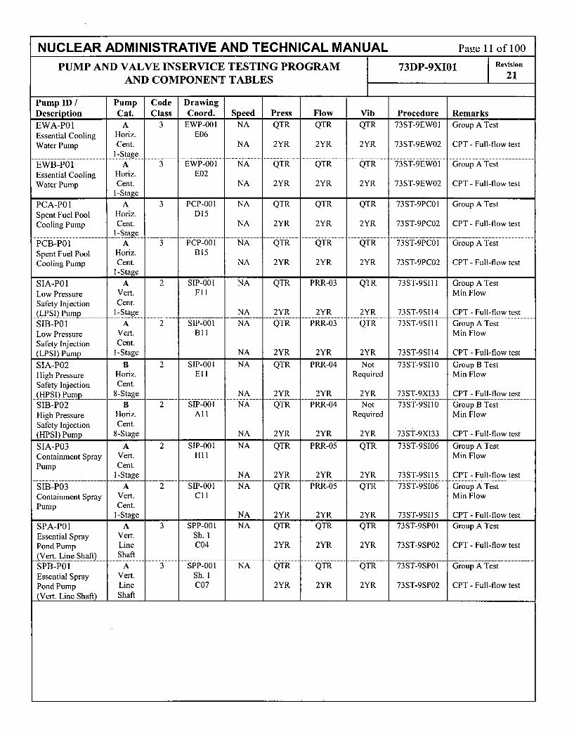
NUCLEAR ADMINISTRATIVE AND TECHNICAL MANUAL Page 11 of 100
PUMP AND VALVE INSERVICE TESTING PROGRAM 73DP-9XI01 Revision
AND COMPONENT TABLES 21
Pump ID / Pump Code DrawingDescription Cat. Class Coord. Speed Press Flow Vib Procedure RemarksEWA-P01 A 3 EWP-00I NA QTR QTR QTR 73ST-9EWO1 Group A TestEssential Cooling Horiz. E06Water Pump Cent. NA 2YR 2YR 2YR 73ST-9EW02 CPT - Full-flow test
.... a............................ I -s t g e .... ... . .... . .EWB-P01 A 3 EWP-001 NA QTR QTR QTR 73ST-9EWO0 Group.A TestEssential Cooling Horiz. E02Water Pump Cent. NA 2YR 2YR 2YR 73ST-9EW02 CPT - Full-flow test
I-StagePCA-PO1 A 3 PCP-001 NA QTR QTR QTR 73ST-9PCOI Group A TestSpent Fuel Pool Horiz. D15Cooling Pump Cent. NA 2YR 2YR 2YR 73ST-9PC02 CPT - Full-flow test
............ . . ...... .-.. . . . . . . . . . . . . . . . . . . . . . . . . . . . . . . . . . . . . . . . . . . . ........ ..... ta g e ------- ------ --.. . . . . . . . .PCB-POI A 3 PCP-001 NA QTR QTR QTR 73ST-9PCOI Group A TestSpent Fuel Pool Horiz. B 15Cooling Pump Cent. NA 2YR 2YR 2YR 73ST-9PC02 CPT - Full-flow test
I-StageSIA-P01 A 2 SIP-001 NA QTR PRR-03 QTR 73ST-9S11 Group A TestLow Pressure Vert. Fl1 Min FlowSafety Injection Cent.(LPSI) Pump- _ -Stage NA 2YR 2YR 2YR 73ST-9SI14 CPT - Full-flow test
SIB-POI A 2 SIP-001 NA QTR PRR-03 QTR 73ST-9SI11i Group A TestLow Pressure Vert. B 11 Min FlowSafety Injection Cent.(LPSI) Pump I-Stage NA 2YR 2YR 2YR 73ST-9SI14 CPT - Full-flow test
SIA-P02 B 2 SIP-001 NA QTR PRR-04 Not 73ST-9SI10 Group B TestHigh Pressure Horiz. El I Required Min FlowSafety Injection Cent._HPSI)PumR _ 8-Stage NA 2YR 2YR 2YR 73ST-9XI33 CPT - Full-flow test
SIB-P02 B 2 SIP-001 NA QTR PRR-04 Not 73ST-9SI10 Group B TestHigh Pressure Horiz. Al I Required Min FlowSafety Injection Cent.(HPSI) Pump 8-Stage NA 2YR 2YR 2YR 73sT-9XI33 CPT - Full-flow test
SIA-P03 A 2 SIP-001 NA QTR PRR-05 QTR 73ST-9SI06 Group A TestContainment Spray Vert. H 11 Min FlowPump Cent.
I-Stage NA 2YR 2YR 2YR 73ST-9SI15 CPT - Full-flow test
SEB-P03 A 2 SIP-001 NA QTR PRR-05 QTR 73ST-9SI06 Group A TestContainment Spray Vert. CI1 Min FlowPump Cent.
I-Stage NA 2YR 2YR 2YR 73ST-9SI15 CPT - Full-flow test
SPA-POI A 3 SPP-001 NA QTR QTR QTR 73ST-9SP01 Group A TestEssential Spray Vert. Sh. IPond Pump Line C04 2YR 2YR 2YR 73ST-9SP02 CPT - Full-flow test
._±yert. Line Shaft) ShaftSPB-P01 A 3 SPP-001 NA QTR QTR QTR 73ST-9SP01 Group A TestEssential Spray Vert. Sh. 1Pond Pump Line C07 2YR 2YR 2YR 73ST-9SP02 CPT - Full-flow test(Vert. Line Shaft) Shaft

NUCLEAR ADMINISTRATIVE AND TECHNICAL MANUAL Page 12 of 100
PUMP AND VALVE INSERVICE TESTING PROGRAM 73DP-9XI01 Revision
AND COMPONENT TABLES 2
Drawing Size (in) Cat. CSJ/Valve ID Coord/Sht# Type A/P ROJ/Description Code Class Act. S.P. Test Freq Procedure VRR Remarks
AFAV007 AFP-001 8 C BDC CMP 73ST-9AF04 Notes 1,2, 3, 4
TURBINE-DRIVEN AFW PUMP SUCTION D07 CK ACTIVE CVO CMP 73ST-9AF04CHECK VALVE FROM CONDENSATE 3 SA 0STORAGE TANK
AFAV015 AFP-001 6 C CVC QTR 73ST-9AF02 Notes 1,2, 3
TURBINE-DRIVEN AUXILIARY E05 CK ACTIVE CVO CSD 73ST-9AF02 CSJ-01FEEDWATER PUMP DISCHARGE CHECK 3 SA O/CVALVE
AFBV022 AFP-001 8 C BDC CMP 73ST-9AF05 Notes 1,2, 3, 4
MOTOR-DRIVEN AFW PUMP SUCTION C07 CK ACTIVE CVO CMP 73ST-9AF05CHECK VALVE FROM CONDENSATE 3 SA 0STORAGE TANK
AFBV024 AFP-001 6 C CVC QTR 73ST-9AF03 Notes 1,2, 3
MOTOR-DRIVEN AUXILIARY FEEDWATER C05 CK ACTIVE CVO CSD 73ST-9AF05 CSJ-01PUMP DISCHARGE CHECK VALVE 3 SA O/C
AFBHV0030 AFP-001 6 B FSC QTR 73ST-9XI05 VRR-01 Note 5QTR FS FOR PRA/RA
MOTOR-DRIVEN AFW PUMP TO SG #1 804 GL ACTIVE FSO QTR 73ST-9XI05 VRR-01 18M ST FOR TS 3.3.5.4FLOW CONTROL VALVE 3MO /C STC 18M 73ST-9XI05 VRR-01
STO 18M 73ST-9XI05 VRR-01
AFBHV0031 AFP-001 6 B FSC QTR 73ST-9XI05 VRR-01 Note 5QTR FS FOR PRA/RAMOTOR-DRIVEN AFW PUMP TO SG #2 B04 GL ACTIVE FSO QTR 73ST-9XI05 VRR-01 18M ST FOR TS 3.3.5.4FLOW CONTROL VALVE 3 MO O/C STC 18M 73ST-9XI05 VRR-01
STO 18M 73ST-9XI05 VRR-01
AFAHV0032 AFP-001 6 B FSC QTR 73ST-9XI05 VRR-01 Note 5QTR FS FOR PRA/RA
TURBINE-DRIVEN AFW PUMP TO SG #1 D04 GL ACTIVE FSO QTR 73ST-9XI05 VRR-01 18M ST FOR TS 3.3.5.4FLOW CONTROL VALVE 3 MO O/C STC 18M 73ST-9XI05 VRR-01
STO 18M 73ST-9XI05 VRR-01
AFCHV0033 AFP-001 6 B FSC QTR 73ST-9XI05 VRR-01 Note 5QTR FS FOR PRA/RATURBINE-DRIVEN AFW PUMP TO SG #2 C04 GL ACTIVE FSO QTR 73ST-9XI05 VRR-01 18M ST FOR TS 3.3.5.4FLOW CONTROL VALVE 3 MO O/C STC 18M 73ST-9XI05 VRR-01
STO 18M 73ST-9XI05 VRR-01
AFBUVO034 AFP-001 6 B FSC QTR 73ST-9XI05 VRR-01 Note 5QTR FS FOR PRN/RAMOTOR-DRIVEN AFW PUMP TO SG #1 B03 GA ACTIVE FSO QTR 73ST-9XI05 VRR-01 18M ST FOR TS 3.3.5.4ISOLATION VALVE (PEN. 75) 2 MO O/C STC 18M 73ST-9XI05 VRR-01
STO 18M 73ST-9XI05 VRR-01
AFBUVO035 AFP-001 6 B FSC QTR 73ST-9XI05 VRR-01 Note5QTR FS FOR PRNIRAMOTOR-DRIVEN AFW PUMP TO SG #2 C03 GA ACTIVE FSO QTR 73ST-9XI05 VRR-01 18M ST FOR TS 3.3.5.4ISOLATION VALVE (PEN. 76) 2 MO O/C STC 18M 73ST-9XI05 VRR-01
STO 18M 73ST-9X[05 VRR-01
AFCUVO036 AFP-001 6 B FSC QTR 73ST-9XI05 VRR-01 Note5QTR FS FOR PRA/RATURBINE-DRIVEN AFW PUMP TO SG #1 D03 GA ACTIVE FSO QTR 73ST-9XI05 VRR-01 18M ST FOR TS 3.3.5.4ISOLATION VALVE (PEN. 75) 2 MO O/C STC 18M 73ST-9XI05 VRR-01
STO 18M 73ST-9XI05 VRR-01
AFAUVO037 AFP-001 6 B FSC QTR 73ST-9XI05 VRR-01 Note 5QTR FS FOR PRA/RATURBINE-DRIVEN AFW PUMP TO SG #2 D03 GA ACTIVE FSO QTR 73ST-9XI05 VRR-01 18M ST FOR TS 3.3.5.4ISOLATION VALVE (PEN. 76) 2 MO O/C STC 18M 73ST-9X10⁵ VRR-01
STO 18M 73ST-9XI05 VRR-01
AFAHV0054 AFP-001 4 B FSO QTR 73ST-9AF02 VRR-01 Note 5
TURBINE-DRIVEN AFW PUMP G04 GL ACTIVE QTR FS FOR PRNRA
TRIP/THROTTLE VALVE N MO 0

NUCLEAR ADMINISTRATIVE AND TECHNICAL MANUAL Page 13 of 100
PUMP AND VALVE INSERVICE TESTING PROGRAM 73DP-9XI01 Reviion
AND COMPONENT TABLES 2
Drawing Size (in) Cat. CSJ/Valve ID Coord/Sht# Type A/P ROJ/Description Code Class Act. S.P. Test Freq Procedure VRR Remarks
AFAV079 AFP-001 6 C CVC CSD 73ST-9AF04 Notes 1, 2, 3. Also exercised
AFW TO SG #1 CHECK VALVE (PEN. 75) E02 CK ACTIVE CVO CSD 73ST-9AF04 CSJ-02 open in 73ST-9AF05.2 SA O/C
AFBV080 AFP-001 6 C CVC CSD 73ST-9AF05 Notes 1,2, 3. Also exercisedAFW TO SG #2 CHECK VALVE (PEN. 76) C02 CK ACTIVE CVO CSD 73ST-9AF05 CSJ-02 open in 73ST-9AF05.
2 SA O/C
AFAV096 AFP-001 4 C BDO CMP 40OP-9AF01 Notes 1,2, 3, 4
AUX STEAM SUPPLY CHECK VALVE TO G02 CK ACTIVE CVC CMP 73ST-9X136AFW TURBINE 3 SA C
AFBPSVO106 AFP-001 0.75 C SV 10Y 73ST-9ZZ20 Thermal Relief Valve
PRESSURE LOCKING RELIEF VALVE FOR B03 SV ACTIVEAFBUV0034 BONNET(PEN. 75) 2 SA O/C
AFBPSVO107 AFP-001 0.75 C SV 10Y 73ST-9ZZ20 Thermal Relief ValvePRESSURE LOCKING RELIEF VALVE FOR C03 SV ACTIVEAFBUVO035 BONNET (PEN. 76) 2 SA O/C
AFAPSV0108 AFP-001 0.75 C SV 10Y 73ST-9ZZ20 Thermal Relief Valve
PRESSURE LOCKING RELIEF VALVE FOR D03 SV ACTIVEAFCUVO036 BONNET (PEN. 75) 2 SA O/C
AFAPSVO109 AFP-001 0.75 C SV 10Y 73ST-9ZZ20 Thermal Relief Valve
PRESSURE LOCKING RELIEF VALVE FOR D03 SV ACTIVEAFAUVO037 BONNET (PEN. 76) 2 SA O/C
AFAV137 AFP-001 6 C BDC CMP 73ST-9AF04 Notes 1,2, 3, 4
TURBINE DRIVEN AFW PUMP D06 CK ACTIVE CVO CMP 73ST-9AF04DISCHARGE CHECK VALVE 3 SA 0
AFBV138 AFP-001 6 C BDC CMP 73ST-9AF05 Notes 1,2, 3, 4
MOTOR DRIVEN AFW DISCHARGE CHECK C06 CK ACTIVE CVO CMP 73ST-9AF05VALVE 3 SA 0
CHEVM70 CHP-001 3 AC AJ CLR 73ST-9CLO1 Notes 1,2, 3, 4CHARGING TO REGENERATIVE HEAT F15 CK ACTIVE CVC CMP 73ST-9CLO1EXCHANGER INLET INBOARD CIV (PEN. 2 SA O/C41) CVO CMP 73ST-9CH06
CHNVI44 CHP-002 3 B FSC 2YR 73ST-9XI44MANUAL ISOLATION VALVE FROM RWT B14 DI ACTIVE FSO 2YR 73ST-9XI44TO SPENT FUEL POOL CLEANUP PUMPS 3 MA O/C
CHNV154 CHP-002 3 C BDC CMP 40ST-9CH04 Notes 1,2, 3, 4BORIC ACID MAKEUP PUMP DISCHARGE B13 CK ACTIVE CVO CMP 40ST-9CH04CHECK VALVE 3 SA 0
CHNV155 CHP-002 3 C BDC CMP 40ST-9CH04 Notes 1,2, 3, 4
BORIC ACID MAKEUP PUMP DISCHARGE B13 CK ACTIVE CVO CMP 40ST-9CH04CHECK VALVE 3 SA 0
CHNV164 CHP-002 3 B FSO 2YR 73ST-9XI45
BORIC ACID MAKEUP FILTER BYPASS D11 DI ACTIVELINE ISOLATION VALVE 3 MA 0
CHAV177 CHP-002 3 C BDC CMP 40ST-9CH04 Notes 1,2, 3, 4
BORIC ACID MAKEUP CHECK VALVE TO B07 CK ACTIVE CVO CMP 40ST-9CH04VCT OUTLET 2 SA 0
CHAV190 CHP-002 3 C BDC CMP 40ST-9CH04 Notes 1,2, 3, 4RWT TO CHARGING PUMP SUCTION A07 CK ACTIVE CVO CMP 40ST-9CH04CHECK VALVE 2 SA 0

NUCLEAR ADMINISTRATIVE AND TECHNICAL MANUAL Page 14 of 100
PUMP AND VALVE INSERVICE TESTING PROGRAM 73DP-9XI01 I Revision
AND COMPONENT TABLES 21
Drawing Size (in) Cat. CSJIValve ID CoordlSht# Type A/P ROJ/Description Code Class Act. S.P. Test Freq Procedure VRR Remarks
CHBHV0203 CHP-001 2 B FSC CSD 73ST-9XI22 CSJ-03 Cycled every 18 months per TRM
AUXILIARY PRESSURIZER SPRAY VALVE H10 GL ACTIVE FSO CSD 73ST-9XI22 CSJ-03 TSR 3.4.100.31 so O/C FTC CSD 73ST-9XI22 CSJ-03
STC CSD 73ST-9XI22 CSJ-03
STO CSD 73ST-9XI22 CSJ-03
VP 2YR 73ST-9X127
CHAHV0205 CHP-001 2 B FSC CSD 73ST-9XI22 CSJ-03 Cycled every 18 months per TRM
AUXILIARY PRESSURIZER SPRAY VALVE Hi1 GL ACTIVE FSO CSD 73ST-9XI22 CSJ-03 TSR 3.4.100.31 so O/C FTC CSD 73ST-9XI22 CSJ-03
STC CSD 73ST-9XI22 CSJ-03
STO CSD 73ST-9X122 CSJ-03
VP 2YR 73ST-9XI27
CHEHV0239 CHP-001 2 B FSC QTR 73ST-9X10⁶NORMAL CHARGING FLOWPATH Gl1 GL ACTIVE FTC QTR 73ST-9XI06ISOLATION VALVE 2 AO O/C STC QTR 73ST-9XI06
VP 2YR 73ST-9X10⁶
CHEPDV0240 CHP-001 2 B FSC QTR 73ST-9XI06NORMAL CHARGING FLOWPATH Gl1 GL ACTIVE FTC QTR 73ST-9XI06ISOLATION VALVE 1 AO O/C STC QTR 73ST-9XI06
VP 2YR 73ST-9X10⁶
CHBHV0255 CHP-001 1.5 A AJ CLR 73ST-9CLO1 Note 5RCP SEAL INJECTION OUTBOARD CIV G04 GL ACTIVE FSC 1CY 73ST-9X122 VRR-01(PEN. 72) 2 MO C
CHBV305 CHP-002 20 C CVC CMP 73ST-9XI39 Notes 1, 2, 3, 4
REFUELING WATER TANK OUTLET B15 CK ACTIVE CVO CMP 73ST-9S111CHECK VALVE TO SI SUCTION HEADER 2 SA O/C
CHAV306 CHP-002 20 C CVC CMP 73ST-9XI39 Notes 1,2, 3, 4
REFUELING WATER TANK OUTLET C13 CK ACTIVE CVO CMP 73ST-9SI11CHECK VALVE TO SI SUCTION HEADER 2 SA O/C
CHAPSV0315 CHP-002 0.75 C SV 10Y 73ST-9ZZ20
CHARGING PUMP SUCTION PRESSURE C05 SV ACTIVERELIEF VALVE 2 SA O/C
CHAV316 CHP-002 4 B FSC 2YR 73ST-9XI44CHARGING PUMP CHA-p01 NORMAL B05 DI ACTIVE FSO 2YR 73ST-9XI44SUCTION FROM VCT MANUAL ISOLATION 2 MA O/CVALVE
CHBPSV0318 CHP-002 0.75 C SV 10Y 73ST-9ZZ20 Thermal Relief ValveCHARGING PUMP SUCTION PRESSURE F05 SV ACTIVERELIEF VALVE 2 SA O/C
CHBV319 CHP-002 4 B FSC 2YR 73ST-9XI45CHARGING PUMP CHB-P01 NORMAL D05 DI ACTIVE FSO 2YR 73ST-9X145SUCTION FROM VCT MANUAL ISOLATION 2 MA O/CVALVE
CHEPSV0321 CHP-002 0.75 C SV 10Y 73ST-9ZZ20CHARGING PUMP SUCTION PRESSURE H05 SV ACTIVE
RELIEF VALVE 2 SA O/C
CHEV322 CHP-002 4 B FSC 2YR 73ST-9XI44CHARGING PUMP CHE-p01 NORMAL G05 DI ACTIVE FSO 2YR 73ST-9X144SUCTION FROM VCT MANUAL ISOLATION 2 MA O/CVALVE
CHEPSV0324 CHP-002 0.75 C SV 10Y 73ST-9ZZ20CHARGING PUMP DISCHARGE G02 SV ACTIVEPRESSURE RELIEF VALVE 2 SA O/C

NUCLEAR ADMINISTRATIVE AND TECHNICAL MANUAL Page 15 of 100
PUMP AND VALVE INSERVICE TESTING PROGRAM 73DP-9XI01 Revision
AND COMPONENT TABLES 21
Drawing Size (in) Cat. CSJIValve ID Coord/Sht# Type A/P ROJ/Description Code Class Act. S.P. Test Freq Procedure VRR Remarks
CHBPSV0325 CHP-002 0.75 C SV 10Y 73ST-9ZZ20
CHARGING PUMP DISCHARGE E02 SV ACTIVEPRESSURE RELIEF VALVE 2 SA O/C
CHAPSV0326 CHP-002 0.75 C SV 10Y 73ST-9ZZ20
CHARGING PUMP DISCHARGE C02 SV ACTIVEPRESSURE RELIEF VALVE 2 SA O/C
CHBV327 CHP-002 3 B FSC 2YR 73ST-9XI45
CHARGING PUMP ALTERNATE SUCTION E05 DI ACTIVE FSO 2YR 73ST-9X145COMMON ISOLATION VALVE 2 MA O/C
CHAV328 CHP-002 2 C BDC QTR 73ST-9CH06 Notes 1,2, 3
CHARGING PUMP CHA-P01 DISCHARGE B02 CK ACTIVE CVO QTR 73ST-9CH06CHECK VALVE 2 SA 0
CHBV331 CHP-002 2 C BDC QTR 73ST-9CH06 Notes 1,2, 3
CHARGING PUMP CHB-P01 DISCHARGE E02 CK ACTIVE CVO QTR 73ST-9CH06CHECK VALVE 2 SA 0
CHEV334 CHP-002 2 C BDC QTR 73ST-9CH06 Notes 1,2, 3
CHARGING PUMP CHE-P01 DISCHARGE G02 CK ACTIVE CVO QTR 73ST-9CH06CHECK VALVE 2 SA 0
CHEV429 CHP-001 2 C BDC CMP 73ST-9ZZ25 Notes 1,2, 3, 4
COMMON CHARGING LINE TO D16 CK ACTIVE CVO CMP 40OP-90OP05REGENERATIVE HEAT EXCHANGER 2 SA 0CHECK VALVE
CHEV431 CHP-001 2 C BDC CMP 73ST-9ZZ25 Notes 1,2, 3, 4
PRESSURIZER AUXILIARY SPRAY CHECK G09 CK ACTIVE CVO CMP 73ST-9XI27VALVE 1 SA 0
CHEV433 CHP-001 2 C BDC CMP 73ST-9ZZ25 Notes 1,2, 3, 4
CHARGING LINE CHECK VALVE TO RCS G09 CK ACTIVE CVO CMP 40OP-90OP051 SA 0
CHEV435 CHP-001 2 C BDC CMP 73ST-9ZZ25 Notes 1,2, 3, 4
REGENERATIVE HEAT EXCHANGER Fll CK ACTIVE CVO CMP 73ST-9CH06OUTLET CHECK VALVE 1 SA 0
CHEV494 CHP-003 1.5 AC AJ CLR 73ST-9CLO1 Notes 1,2, 3, 4
REACTOR MAKEUP WATER SUPPLY E15 CK ACTIVE BDO CMP 40OP-9CH01CHECK VALVE TO RDT INBOARD CIV 2 SA C(PEN. 45) CVC CMP 73ST-9CL01
CHNUV0501 CHP-002 4 B FSC 1CY 73ST-9XI22 VRR-01 Note 5
VOLUME CONTROL TANK OUTLET C07 GA ACTIVEISOLATION VALVE 2 MO C
CHBUV0505 CHP-002 1 A AJ CLR 73ST-9CL01
REACTOR COOLANT SEAL BLEED-OFF H13 GL ACTIVE FSC RFO 73ST-9XI22 ROJ-02OUTBOARD CIV (PEN. 43) 2 AO C FTC RFO 73ST-9XI22 ROJ-02
STC RFO 73ST-9XI22 ROJ-02
VP 2YR 73ST-9XI22
CHAUVO506 CHP-002 1 A AJ CLR 73ST-9CLO1
REACTOR COOLANT SEAL BLEED-OFF H14 GL ACTIVE FSC RFO 73ST-9X122 ROJ-02INBOARD CIV (PEN. 43) 2 AO C FTC RFO 73ST-9XI22 ROJ-02
STC RFO 73ST-9X122 ROJ-02
VP 2YR 73ST-9XI22
CHNUV0514 CHP-002 3 B FSO 1CY 73ST-9XI06 VRR-01 Note5
BORIC ACID MAKEUP TO CHARGING B10 GL ACTIVEPUMP SUCTION ISOLATION VALVE 3 MO 0
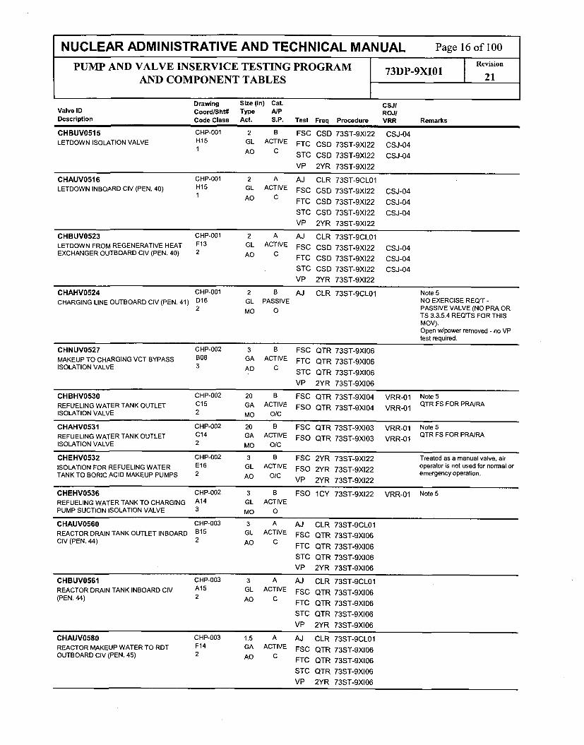
NUCLEAR ADMINISTRATIVE AND TECHNICAL MANUAL Page 16 of 100
PUMP AND VALVE INSERVICE TESTING PROGRAM 73DP-9XI01 Revision
AND COMPONENT TABLES 21
Drawing Size (in) Cat. CsJIValve ID Coord/Sht# Type A/P ROJ/Description Code Class Act. S.P. Test Freq Procedure VRR Remarks
CHBUV0515 CHP-001 2 B FSC CSD 73ST-9XI22 CSJ-04
LETDOWN ISOLATION VALVE H15 GL ACTIVE FTC CSD 73ST-9XI22 CSJ-041 AD C STC CSD 73ST-9XI22 CSJ-04
VP 2YR 73ST-9XI22
CHAUV0516 CHP-001 2 A AJ CLR 73ST-9CL01
LETDOWN INBOARD CIV (PEN. 40) H15 GL ACTIVE FSC CSD 73ST-9XI22 CSJ-041 AO C FTC CSD 73ST-9XI22 CSJ-04
STC CSD 73ST-9XI22 CSJ-04
VP 2YR 73ST-9X122
CHBUV0523 CHP-001 2 A AJ CLR 73ST-9CLO1
LETDOWN FROM REGENERATIVE HEAT F13 GL ACTIVE FSC CSD 73ST-9XI22 CSJ-04EXCHANGER OUTBOARD CIV (PEN. 40) 2 AO C FTC CSD 73ST-9X122 CSJ-04
STC CSD 73ST-9XI22 CSJ-04
VP 2YR 73ST-9X122
CHAHV0524 CHP-O01 2 B AJ CLR 73ST-9CLO1 Note 5
CHARGING LINE OUTBOARD CIV (PEN. 41) D16 GL PASSIVE NO EXERCISE REQ'T -2 MO O PASSIVE VALVE (NO PRA OR
TS 3.3.5.4 REQ'TS FOR THISMOV).Open w/power removed - no VPtest required.
CHNUV0527 CHP-002 3 B FSC QTR 73ST-9XI06
MAKEUP TO CHARGING VCT BYPASS B08 GA ACTIVE FTC QTR 73ST-9XI06ISOLATION VALVE 3 AD C
STC QTR 73ST-9X10⁶VP 2YR 73ST-9X10⁶
CHBHV0530 CHP-002 20 B FSC QTR 73ST-9X10⁴ VRR-01 Note 5
REFUELING WATER TANK OUTLET C15 GA ACTIVE FSO QTR 73ST-9X10⁴ VRR-01 QTR FS FOR PRA/RA
ISOLATION VALVE 2 MO O/C
CHAHV0531 CHP-002 20 B FSC QTR 73ST-9XI03 VRR-01 Note 5
REFUELING WATER TANK OUTLET C14 GA ACTIVE FSO QTR 73ST-9XI03 VRR-01 QTR FS FOR PRA/RA
ISOLATION VALVE 2 MO O/C
CHEHV0532 CHP-002 3 B FSC 2YR 73ST-9XI22 Treated as a manual valve, air
ISOLATION FOR REFUELING WATER E16 GL ACTIVE FSO 2YR 73ST-9X122 operator is not used for normal orTANK TO BORIC ACID MAKEUP PUMPS 2 AO O/C emergency operation.
TANKTO BRICVP~ 2YR 73ST-9XI22
CHEHV0536 CHP-002 3 B FSO 1CY 73ST-9XI22 VRR-01 Note 5
REFUELING WATER TANK TO CHARGING A14 GL ACTIVEPUMP SUCTION ISOLATION VALVE 3 MO 0
CHAUV0560 CHP-003 3 A AJ CLR 73ST-9CLO1
REACTOR DRAIN TANK OUTLET INBOARD B15 GL ACTIVE FSC QTR 73ST-9XI06CIV (PEN. 44) 2 AO C FTC QTR 73ST-9XI06
STC QTR 73ST-9X10⁶
VP 2YR 73ST-9X10⁶
CHBUV0561 CHP-003 3 A AJ CLR 73ST-9CLO1
REACTOR DRAIN TANK INBOARD CIV A15 GL ACTIVE FSC QTR 73ST-9X10⁶(PEN. 44) 2 AO C FTC QTR 73ST-9XI06
STC QTR 73ST-9X10⁶
VP 2YR 73ST-9X10⁶
CHAUV0580 CHP-003 1.5 A AJ CLR 73ST-9CLO1
REACTOR MAKEUP WATER TO RDT F14 GA ACTIVE FSC QTR 73ST-9X10⁶OUTBOARD CIV (PEN. 45) 2 AO C FTC QTR 73ST-9XI06
STC QTR 73ST-9X10⁶
VP 2YR 73ST-9X10⁶

NUCLEAR ADMINISTRATIVE AND TECHNICAL MANUAL Page 17 of 100RevisionPUMP AND VALVE INSERVICE TESTING PROGRAM 73DP-9XI01 21
AND COMPONENT TABLES 21
Drawing Size (in) Cat. CSJ/Valve ID Coord/Sht# Type A/P ROJ/Description Code Class Act. S.P. Test Freq Procedure VRR Remarks
CHAUV0715 CHP-003 0.5 A AJ CLR 73ST-9CLO1
PASS TO RDT CIV (PEN. 45) E13 GL ACTIVE FSC QTR 73ST-9XI062 so C FTC QTR 73ST-9XI06
STC QTR 73ST-9XI06
VP 2YR 73ST-9XI06
CHAV755 CHP-002 3 B FSC 2YR 73ST-9X144CHARGING PUMP CHA-P01 ALTERNATE C05 DI ACTIVE FSO 2YR 73ST-9X144SUCTION MANUAL ISOLATION VALVE 2 MA O/C
CHBV756 CHP-002 3 B FSC 2YR 73ST-9XI45
CHARGING PUMP CHB-P01 ALTERNATE D05 DI ACTIVE FSO 2YR 73ST-9X145SUCTION MANUAL ISOLATION VALVE 2 MA O/C
CHEV757 CHP-002 3 B FSC 2YR 73ST-9XI44
CHARGING PUMP CHE-P01 ALTERNATE F05 DI ACTIVE FSO 2YR 73ST-9XI44SUCTION MANUAL ISOLATION VALVE 2 MA O/C
CHNV835 CHP-001 1.5 AC AJ CLR 73ST-9CLO1 Notes 1,2, 3, 4
RCP SEAL INJECTION SUPPLY LINE G03 CK ACTIVE BDO CMP 40DP-9OP05CHECK VALVE (PEN. 72) 2 SA C CVC CMP 73ST-9CLO1
CHEV854 CHP-001 0.75 A AJ CLR 73ST-9CLO1
CHARGING LINE CHEMICAL ADDITION E15 GL PASSIVEISOLATION VALVE (PEN. 41) 2 MA C
CHBUV0924 CHP-001 0.5 A AJ CLR 73ST-9CLO1
LETDOWN TO PASS CIV (PEN. 40) E14 GL ACTIVE FSC QTR 73ST-9X1062 so C FTC QTR 73ST-9XI06
STC QTR 73ST-9X10⁶
VP 2YR 73ST-9X10⁶
CPBUVO003A CPP-O01 42 B FSC RFO 73ST-9XI23 ROJ-01 Note 5Note 6
CONTAINMENT REFUELING PURGE D05 BF ACTIVE STC 18M 73ST-9XI23 VRR-01 18M STC REQ'D FOR TS 3.3.5.4SUPPLY INBOARD CIV (PEN. 56) 2 MO C
CPBUVO003B CPP-001 42 B FSC RFO 73ST-9X123 ROJ-01 Note 5Note6CONTAINMENT REFUELING PURGE E02 BF ACTIVE STC 18M 73ST-9XI23 VRR-01 18M STC REQ'D FOR TS 3.3.5.4EXHAUST OUTBOARD CIV (PEN. 57) 2 MO C
CPAUVO004A CPP-O01 8 A AJ CLR 73ST-9CL07CONTAINMENT POWER ACCESS PURGE D06 BF ACTIVE FSC QTR 73ST-9XI15SUPPLY OUTBOARD CIV (PEN. 78) 2 AO C
FTC QTR 73ST-9X115STC QTR 73ST-9XI15
VP 2YR 73ST-9XI15
CPAUVO004B CPP-001 8 A AJ CLR 73ST-9CL07
CONTAINMENT POWER ACCESS PURGE D03 BF ACTIVE FSC QTR 73ST-9XI15EXHAUST INBOARD CIV (PEN. 79) 2 AO C FTC QTR 73ST-9XI15
STC QTR 73ST-9XI15
VP 2YR 73ST-9XI15
CPBUVO005A CPP-001 8 A AJ CLR 73ST-9CL07CONTAINMENT POWER ACCESS PURGE D05 BF ACTIVE FSC QTR 73ST-9XI15SUPPLY INBOARD CIV (PEN. 78) 2 AO C FTC QTR 73ST-9XI15
STC QTR 73ST-9XI15
VP 2YR 73ST-9XI15
CPBUVO005B CPP-001 8 A AJ CLR 73ST-9CL07CONTAINMENT POWER ACCESS PURGE C02 BF ACTIVE FSC QTR 73ST-9XI15EXHAUST OUTBOARD CIV (PEN. 79) 2 AO C FTC QTR 73ST-9XI15
STC QTR 73ST-9XI15
VP 2YR 73ST-9XI15

NUCLEAR ADMINISTRATIVE AND TECHNICAL MANUAL Page 18 of 100
PUMP AND VALVE INSERVICE TESTING PROGRAM 73DP-9XI01 Revision
AND COMPONENT TABLES 21
Drawing Size (in) Cat. CSjIValve ID Coord/Sht# Type A/P ROJIDescription Code Class Act. S.P. Test Freq Procedure VRR Remarks
CPAUVO002A CPP-001 42 B FSC RFO 73ST-9XI23 ROJ-01 Note 5Note6CONTAINMENT REFUELING PURGE D06 BF ACTIVE STC 18M 73ST-9XI23 VRR-01 18M STC REQ'D FOR TS 3.3.5.4SUPPLY OUTBOARD CIV (PEN. 56) 2 MO C
CPAUVO002B CPP-001 42 B FSC RFO 73ST-9X123 ROJ-01 Note 5Note6CONTAINMENT REFUELING PURGE E03 BF ACTIVE STC 18M 73ST-9XI23 VRR-01 18M STC REQ'D FORTS 3.3.5.4EXHAUST INBOARD CIV (PEN. 57) 2 MO C
CTAHV0001 CTP-001 10 B FSC QTR 73ST-9X10⁵ VRR-01 The tests in the open direction arefor an augmented functionAFN-P01 SUCTION ISOLATION VALVE E02 BF ACTIVE FSO QTR 73ST-9XI05 VRR-01 Note 5FROM CONDENSATE STORAGE TANK 3 MO C QTR FS FOR PRA/RA.
CTAHV0004 CTP-001 10 B FSC QTR 73ST-9XI05 VRR-01 The tests in the open direction arefor an augmented functionAFN-P01 SUCTION ISOLATION VALVE E03 BF ACTIVE FSO QTR 73ST-9XI05 VRR-01 Note 5FROM CONDENSATE STORAGE TANK 3 MO C QTR FS FOR PR5RA.
CTAV016 CTP-001 3 C BDC QTR 73ST-9CT01 Notes 1,2, 3.
CONDENSATE TRANSFER PUMP C04 CK ACTIVE CVO QTR 73ST-9CT01DISCHARGE CHECK VALVE 3 SA 0
CTAV018 CTP-001 3 B FSC QTR 73ST-9CT01
CONDENSATE TRANSFER TO SPENT C03 GA ACTIVE FSO QTR 73ST-9CT01FUEL POOL ISOLATION 3 MA O/C
CTBV019 CTP-001 3 B FSC QTR 73ST-9CT01
CONDENSATE TRANSFER TO SPENT B03 GA ACTIVE FSO QTR 73ST-9CT01FUEL POOL ISOLATION 3 MA O/C
CTBV020 CTP-001 3 C BDC QTR 73ST-9CT01 Notes 1,2, 3.
CONDENSATE TRANSFER PUMP B04 CK ACTIVE CVO QTR 73ST-9CT01DISCHARGE CHECK VALVE 3 SA 0
CTAV037 CTP-001 3 C BDC QTR 73ST-9CT01 Notes 1,2, 3.
CONDENSATE TRANSFER TO SPENT C04 CK ACTIVE CVO QTR 73ST-9CT01FUEL POOL CHECK VALVE 3 SA 0
CTBV038 CTP-001 3 C BDC QTR 73ST-9CT01 Notes 1,2, 3.
CONDENSATE TRANSFER TO SPENT B04 CK ACTIVE CVO QTR 73ST-9CT01FUEL POOL CHECK VALVE 3 SA 0
DFAV012 DFP-001 2 C BDC CMP 73ST-9DF01 Notes 1,2, 3, 4
FUEL OIL TRANSFER PUMP DISCHARGE D06 CK ACTIVE CVO CMP 73ST-9DF01CHECK VALVE 3 SA 0
DFBV019 DFP-001 2 C BDC CMP 73ST-9DF01 Notes 1,2, 3, 4
FUEL OIL TRANSFER PUMP DISCHARGE D02 CK ACTIVE CVO CMP 73ST-9DF01CHECK VALVE 3 SA 0
DFAV041 DFP-001 1 B FSC 2YR 73ST-9XI44
DIESEL FUEL OIL FILTER DP GAUGE H07 GL ACTIVE FSO 2YR 73ST-9XI44MANUAL ISOLATION VALVE 3 MA C
DFAV042 DFP-001 1 B FSC 2YR 73ST-9X144
DIESEL FUEL OIL FILTER DP GAUGE G07 GL ACTIVE FSO 2YR 73ST-9X144MANUAL ISOLATION VALVE 3 MA C
DFBV051 DFP-001 1 B FSC 2YR 73ST-9XI45
DIESEL FUEL OIL FILTER DP GAUGE H03 GL ACTIVE FSO 2YR 73ST-9XI45MANUAL ISOLATION VALVE 3 MA C
DFBV052 DFP-001 1 B FSC 2YR 73ST-9XI45
DIESEL FUEL OIL FILTER DP GAUGE G03 GL ACTIVE FSO 2YR 73ST-9X145MANUAL ISOLATION VALVE 3 MA C
DGAPSVO005 DGP-001 sht 9 1 C SV 10Y 73ST-9ZZ20
EDG START AIR RECEIVER SAFETY H06 SV ACTIVERELIEF VALVE 3 SA O/C
DGBPSVO006 DGP-001 sht 9 1 C SV 10Y 73ST-9ZZ20
EDG START AIR RECEIVER SAFETY D06 SV ACTIVERELIEF VALVE 3 SA O/C

NUCLEAR ADMINISTRATIVE AND TECHNICAL MANUAL Page 19 of 100
PUMP AND VALVE INSERVICE TESTING PROGRAM 73DP-9XI01 Revision
AND COMPONENT TABLES 21
Drawing Size (in) Cat. CSJ/Valve ID Coord/Sht# Type A/P ROJ/Description Code Class Act. S.P. Test Freq Procedure VRR Remarks
DGAPSVO007 DGP-001 sht 9 1 C SV 10Y 73ST-9ZZ20EDG START AIR RECEIVER SAFETY F06 SV ACTIVERELIEF VALVE 3 SA O/C
DGBPSVO008 DGP-001 sht9 1 C SV 10Y 73ST-9ZZ20EDG START AIR RECEIVER SAFETY C03 SV ACTIVERELIEF VALVE 3 SA O/C
DGAV066 DGP-001 sht 9 1 C BDO QTR 40ST-9DG01 Notes 1,2, 3. Required in all
EDG STARTING AIR DRYER OUTLET F06 CK ACTIVE CVC QTR 73ST-9XI17 modes including shutdown.
CHECK VALVE 3 SA C
DGAV067 DGP-001 sht 9 1 C BDO QTR 40ST-9DG01 Notes 1,2, 3. Required in all
EDG STARTING AIR DRYER OUTLET G06 CK ACTIVE CVC QTR 73ST-9XI17 modes including shutdown.
CHECK VALVE 3 SA C
DGBV068 DGP-001 sht 9 1 C BDO QTR 40ST-9DG02 Notes 1,2, 3. Required in all
EDG STARTING AIR DRYER OUTLET D06 CK ACTIVE CVC QTR 73ST-9XI18 modes including shutdown.
CHECK VALVE 3 SA C
DGBV069 DGP-001 sht 9 1 C BDO QTR 40ST-9DG02 Notes 1, 2, 3. Required in all
EDG STARTING AIR DRYER OUTLET C06 CK ACTIVE CVC QTR 73ST-9XI18 modes including shutdown.
CHECK VALVE 3 SA C
DWEV061 DWP-002 2 A AJ CLR 73ST-9CLO1
DW SUPPLY HEADER OUTSIDE C03 GL PASSIVECONTAINMENT ISOLATION VALVE (PEN. 6) 2 MA C
DWEV062 DWP-002 2 A AJ CLR 73ST-9CLO1
DW SUPPLY HEADER INSIDE C02 GL PASSIVECONTAINMENT ISOLATION VALVE (PEN. 6) 2 MA C
ECAV038 ECP-001 1.5 C BDO CMP 73ST-9ZZ25 Notes 1,3, 4
MAKEUP LINE CHECK VALVE FROM DW D07 CK ACTIVE CVC CMP 73ST-9ZZ25 Disassembly and Inspection3 SA C
ECAV041 ECP-001 1.5 C BDO CMP 73ST-9ZZ25 Notes 1,3, 4
MAKEUP LINE CHECK VALVE FROM CT C07 CK ACTIVE CVC CMP 73ST-9ZZ25 Disassembly and Inspection3 SA C
ECAV043 ECP-001 1 C BDO CMP 73ST-9ZZ25 Notes 1,3, 4
NITROGEN SUPPLY CHECK VALVE TO EC C07 CK ACTIVE CVC CMP 73ST-9ZZ25 Disassembly and Inspection
EXPANSION TANK 3 SA C
ECBV060 ECP-001 1.5 C BDO CMP 73ST-9ZZ25 Notes 1,3, 4
MAKEUP LINE CHECK VALVE FROM DW D03 CK ACTIVE CVC CMP 73ST-9ZZ25 Disassembly and Inspection3 SA C
ECBV064 ECP-001 1 C BDO CMP 73ST-9ZZ25 Notes 1,3, 4
NITROGEN SUPPLY CHECK VALVE TO EC C03 CK ACTIVE CVC CMP 73ST-9ZZ25 Disassembly and Inspection
EXPANSION TANK 3 SA C
ECBV072 ECP-001 1.5 C BDO CMP 73ST-9ZZ25 Notes 1,3, 4
MAKEUP LINE CHECK VALVE FROM CT D03 CK ACTIVE CVC CMP 73ST-97725 Disassembly and Inspection3 SA C
ECAPSVO075 ECP-001 1.5 C SV 10Y 73ST-9ZZ20EC EXPANSION TANK RELIEF VALVE D06 SV ACTIVE
3 SA O/C
ECBPSVO076 ECP-001 1.5 C SV 10Y 73ST-9ZZ20EC EXPANSION TANK RELIEF VALVE D03 SV ACTIVE
3 SA O/C
ECAPSVO095 ECP-001 1 C SV 10Y 73ST-9ZZ20 Thermal Relief Valve
ESF SWITCHGEAR ROOM ESSENTIAL E05 SV ACTIVEACU RELIEF VALVE 3 SA O/C
ECBPSVO096 ECP-001 1 C SV 10Y 73ST-9ZZ20 Thermal Relief Valve
ESF SWITCHGEAR ROOM ESSENTIAL E02 SV ACTIVEACU RELIEF VALVE 3 SA O/C

NUCLEAR ADMINISTRATIVE AND TECHNICAL MANUAL Page 20 of 100
PUMP AND VALVE INSERVICE TESTING PROGRAM 73DP-9XI01 Revision
AND COMPONENT TABLES 21
Drawing Size (in) Cat. CSJ/Valve ID Coord/Sht# Type A/P ROJIDescription Code Class Act. S.P. Test Freq Procedure VRR Remarks
ECAPSVO097 ECP-001 1 C SV 10Y 73ST-9ZZ20 Thermal Relief Valve
CONTROL ROOM ESSENTIAL ACU RELIEF E07 SV ACTIVEVALVE 3 SA O/C
ECBPSVO098 ECP-001 1 C SV 10Y 73ST-9ZZ20 Thermal Relief Valve
CONTROL ROOM ESSENTIAL ACU RELIEF E04 SV ACTIVEVALVE 3 SA O/C
ECAPSVO099 ECP-001 1 C SV 10Y 73ST-9ZZ20 Thermal Relief Valve
WEST ELECTRICAL PENETRATION ROOM F07 SV ACTIVEESSENTIAL ACU RELIEF VALVE 3 SA O/C
ECBPSVO100 ECP-001 1 C SV 10Y 73ST-97720 Thermal Relief Valve
EAST ELECTRICAL PENETRATION ROOM F03 SV ACTIVEESSENTIAL ACU RELIEF VALVE 3 SA O/C
ECAPSVO101 ECP-001 1 C SV 10Y 73ST-9ZZ20 Thermal Relief Valve
EW PUMP ROOM ESSENTIAL ACU RELIEF F06 SV ACTIVEVALVE 3 SA O/C
ECBPSVO102 ECP-001 1 C SV 10Y 73ST-9ZZ20 Thermal Relief Valve
EW PUMP ROOM ESSENTIAL ACU RELIEF F02 SV ACTIVEVALVE 3 SA O/C
ECAPSV0103 ECP-001 1 C SV 10Y 73ST-9ZZ20 Thermal Relief Valve
CS PUMP ROOM ESSENTIAL ACU RELIEF H07 SV ACTIVEVALVE 3 SA O/C
ECBPSVO104 ECP-001 1 C SV 10Y 73ST-9ZZ20 Thermal Relief Valve
CS PUMP ROOM ESSENTIAL ACU RELIEF H04 SV ACTIVEVALVE 3 SA O/C
ECAPSV0105 ECP-001 1 C SV 10Y 73ST-9ZZ20 Thermal Relief Valve
HPSI PUMP ROOM ESSENTIAL ACU H06 SV ACTIVERELIEF VALVE 3 SA O/C
ECBPSVO106 ECP-001 1 C SV 10Y 73ST-9ZZ20 Thermal Relief Valve
HPSI PUMP ROOM ESSENTIAL ACU H03 SV ACTIVERELIEF VALVE 3 SA O/C
ECAPSV0107 ECP-001 1 C SV 10Y 73ST-9ZZ20 Thermal Relief Valve
LPSI PUMP ROOM ESSENTIAL ACU H05 SV ACTIVERELIEF VALVE 3 SA O/C
ECBPSVO108 ECP-001 1 C SV 10Y 73ST-9ZZ20 Thermal Relief Valve
LPSI PUMP ROOM ESSENTIAL ACU H02 SV ACTIVERELIEF VALVE 3 SA O/C
ECBPSVOI09 ECP-001 1 C SV 10Y 73ST-9ZZ20 Thermal Relief Valve
AFW PUMP ROOM ESSENTIAL ACU F04 SV ACTIVERELIEF VALVE 3 SA O/C
ECAPSVO117 ECP-001 1 C SV 10Y 73ST-9ZZ20 Thermal Relief Valve
AFW PUMP ROOM ESSENTIAL ACU F05 SV ACTIVERELIEF VALVE 3 SA O/C
ECBPSVO120 ECP-001 1 C SV 10Y 73ST-9ZZ20 Thermal Relief Valve
DC EQUIPMENT ROOM ESSENTIAL ACU E03 SV ACTIVERELIEF VALVE 3 SA O/C
ECAPSVO121 ECP-001 1 C SV 10Y 73ST-9ZZ20 Thermal Relief Valve
DC EQUIPMENT ROOM ESSENTIAL ACU E06 SV ACTIVERELIEF VALVE 3 SA O/C
EWAPSVO047 EWP-001 1 C SV 10Y 73ST-9ZZ20 Thermal Relief Valve
SHUTDOWN HEAT EXCHANGER RELIEF B07 SV ACTIVEVALVE 3 SA O/C
EWBPSVO048 EWP-001 1 C SV 10Y 73ST-9ZZ20 Thermal Relief Valve
SHUTDOWN HEAT EXCHANGER RELIEF B03 SV ACTIVEVALVE 3 SA O/C
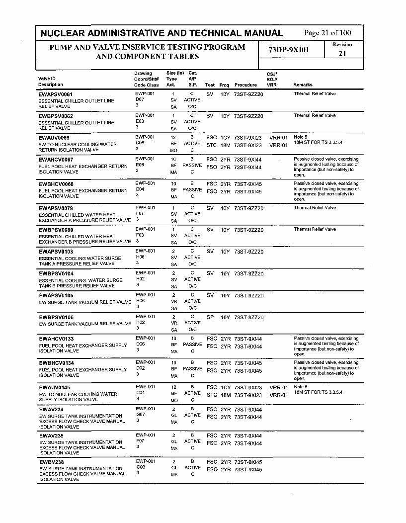
NUCLEAR ADMINISTRATIVE AND TECHNICAL MANUAL Page 21 of 100
PUMP AND VALVE INSERVICE TESTING PROGRAM 73DP-9XI01 Revision
AND COMPONENT TABLESP 21
Drawing Size (in) Cat. CSJ/Valve ID Coord/Sht# Type A/P ROJ/Description Code Class Act. S.P. Test Freq Procedure VRR Remarks
EWAPSVO061 EWP-001 1 C SV 10Y 73ST-9ZZ20 Thermal Relief ValveESSENTIAL CHILLER OUTLET LINE D07 SV ACTIVERELIEF VALVE 3 SA O/C
EWBPSVO062 EWP-001 1 C SV 10Y 73ST-9ZZ20 Thermal Relief Valve
ESSENTIAL CHILLER OUTLET LINE E03 SV ACTIVERELIEF VALVE 3 SA O/C
EWAUVO065 EWP-001 12 B FSC 1CY 73ST-9XI23 VRR-01 Note 5
EW TO NUCLEAR COOLING WATER C08 BF ACTIVE STC 18M 73ST-9XI23 VRR-01 18M ST FOR TS 3.3.5.4
RETURN ISOLATION VALVE 3 MO C
EWAHCV0067 EWP-001 10 B FSC 2YR 73ST-9XI44 Passive closed valve, exercisingFUEL POOL HEAT EXCHANGER RETURN E08 BF PASSIVE FSO 2YR 73ST-9XI44 is augmented testing because ofISOLATION VALVE 3 MA C importance (but non-safety) to
open.
EWBHCV0068 EWP-001 10 B FSC 2YR 73ST-9X145 Passive closed valve, exercisingFUEL POOL HEAT EXCHANGER RETURN E04 BF PASSIVE FSO 2YR 73ST-9XI45 is augmented testing because ofISOLATION VALVE 3 MA C importance (but non-safety) to
open.
EWAPSVO079 EWP-001 1 C SV 10Y 73ST-9ZZ20 Thermal Relief ValveESSENTIAL CHILLED WATER HEAT F07 SV ACTIVEEXCHANGER A PRESSURE RELIEF VALVE 3 SA O/C
EWBPSVO080 EWP-001 1 C SV 10Y 73ST-9ZZ20 Thermal Relief Valve
ESSENTIAL CHILLED WATER HEAT F03 SV ACTIVEEXCHANGER B PRESSURE RELIEF VALVE 3 SA O/C
EWAPSVO103 EWP-001 2 C SV 10Y 73ST-9ZZ20
ESSENTIAL COOLING WATER SURGE H06 SV ACTIVETANK A PRESSURE RELIEF VALVE 3 SA O/C
EWBPSV0104 EWP-001 2 C SV 10Y 73ST-9ZZ20
ESSENTIAL COOLING WATER SURGE H02 SV ACTIVETANK B PRESSURE RELIEF VALVE 3 SA O/C
EWAPSVOI05 EWP-001 2 C SV 10Y 73ST-9ZZ20
EW SURGE TANK VACUUM RELIEF VALVE H06 VR ACTIVE3 SA O/C
EWBPSVO106 EWP-001 2 C SP 10Y 73ST-9ZZ20EW SURGE TANK VACUUM RELIEF VALVE H02 VR ACTIVE
3 SA O/C
EWAHCV0133 EWP-001 10 B FSC 2YR 73ST-9XI44 Passive dosed valve, exercisingFUEL POOL HEAT EXCHANGER SUPPLY D06 BF PASSIVE FSO 2YR 73ST-9XI44 is augmented testing because ofISOLATION VALVE 3 MA C importance (but non-safety) to
open.
EWBHCV0134 EWP-001 10 B FSC 2YR 73ST-9XI45 Passive closed valve, exercisingFUEL POOL HEAT EXCHANGER SUPPLY D02 BF PASSIVE FSO 2YR 73ST-9XI45 is augmented testing because ofISOLATION VALVE 3 MA C importance (but non-safety) to
open.
EWAUVO145 EWP-001 12 B FSC 1CY 73ST-9XI23 VRR-01 Note 5EW TO NUCLEAR COOLING WATER C04 BF ACTIVE STC 18M 73ST-9XI23 VRR-01 18M ST FOR TS 3.3.5.4SUPPLY ISOLATION VALVE 3 MO C
EWAV234 EWP-001 2 B FSC 2YR 73ST-9XI44EW SURGE TANK INSTRUMENTATION G07 GL ACTIVE FSO 2YR 73ST-9XI44EXCESS FLOW CHECK VALVE MANUAL 3 MA CISOLATION VALVE
EWAV235 EWP-001 2 B FSC 2YR 73ST-9XI44EW SURGE TANK INSTRUMENTATION F07 GL ACTIVE FSO 2YR 73ST-9XI44EXCESS FLOW CHECK VALVE MANUAL 3 MA CISOLATION VALVE
EWBV238 EWP-001 2 B FSC 2YR 73ST-9XI45EW SURGE TANK INSTRUMENTATION G03 GL ACTIVE FSO 2YR 73ST-9XI45EXCESS FLOW CHECK VALVE MANUAL 3 MA CISOLATION VALVE

NUCLEAR ADMINISTRATIVE AND TECHNICAL MANUAL Page 22 of 100
PUMP AND VALVE INSERVICE TESTING PROGRAM 73DP-9XI01 Revision
AND COMPONENT TABLES 21
Drawing Size (in) Cat. CSJIValve ID Coord/Sht# Type A/P ROJ/Description Code Class Act. S.P. Test Freq Procedure VRR Remarks
EWBV239 EWP-001 2 B FSC 2YR 73ST-9XI45EW SURGE TANK INSTRUMENTATION F03 GL ACTIVE FSO 2YR 73ST-9XI45EXCESS FLOW CHECK VALVE MANUAL 3 MA CISOLATION VALVE
FPEV089 FPP-006 6 A AJ CLR 73ST-9CLO1FIRE WATER OUTSIDE CONTAINMENT E08 GL PASSIVEISOLATION VALVE (PEN. 7) 2 MA C
FPEV090 FPP-006 6 AC AJ CLR 73ST-9CLO1 Notes 1,2, 3, 4
FIRE WATER INSIDE CONTAINMENT F09 CK ACTIVE CVC CMP 73ST-9CLO1ISOLATION VALVE (PEN. 7) 2 SA O/C CVO CMP 14FT-9FP13
GAAUVO001 GAP-001 1 A AJ CLR 73ST-9CLO1HIGH PRESSURE NITROGEN SUPPLY E07 GL ACTIVE FSC QTR 73ST-9XI07HEADER OUTSIDE CIV (PEN. 30) 2 so C FTC QTR 73ST-9XI07
STC QTR 73ST-9X10⁷
VP 2YR 73ST-9XI07
GAAUVO002 GAP-001 1 A AJ CLR 73ST-9CLO1LOW PRESSURE NITROGEN SUPPLY F03 GL ACTIVE FSC QTR 73ST-9XI07HEADER OUTSIDE CIV (PEN. 29) 2 so C FTC QTR 73ST-9X10⁷
STC QTR 73ST-9XI07
VP 2YR 73ST-9XI07
GAEV011 GAP-001 1 AC AJ CLR 73ST-9CLO1 Notes 1,2, 3, 4.
HIGH PRESSURE NITROGEN SUPPLY D06 CK ACTIVE BDO CMP 40ST-9ZZM1INSIDE CONTAINMENT ISOLATION CHECK 2 SA CVALVE (PEN. 30) CVC CMP 73ST-9CL01
GAEV015 GAP-001 1 AC AJ CLR 73ST-9CLO1 Notes 1,2, 3,4
LOW PRESSURE NITROGEN SUPPLY E02 CK ACTIVE BDO CMP 40DP-9OP05INSIDE CONTAINMENT ISOLATION CHECK 2 SA CVALVE (PEN. 29) CVC CMP 73ST-9CL01
GRAUVO001 GRP-001 1 A AJ CLR 73ST-9CLO1 Note 5QTR FS FOR PRA/RA
CONTAINMENT ISOLATION BETWEEN H07 GL ACTIVE FSC QTR 73ST-9XI07 VRR-01 18M ST FOR TS 3.3.5.4RDT AND GAS SURGE HEADER (PEN 52) 2 MO C STC 18M 73ST-9XI07 VRR-01
GRBUVO002 GRP-001 1 A AJ CLR 73ST-9CLO1CONTAINMENT ISOLATION (SOV) H07 GL ACTIVE FSC QTR 73ST-9XI07BETWEEN RDT AND GAS SURGE 2 so C FHEADER (PEN 52) FTC QTR 73ST-9XI07
STC QTR 73ST-9XI07VP 2YR 73ST-9XI07
HCBUVO044 HCP-001 1 A AJ CLR 73ST-9CLO1CONTAINMENT ATMOSPHERE RADIATION E03 GL ACTIVE FSC QTR 73ST-9XI40MONITOR INLET CIV (PEN 25A) 2 so C FTC QTR 73ST-9XI40
STC QTR 73ST-9X140
VP 2YR 73ST-9X140
HCAUVO045 HCP-001 1 A AJ CLR 73ST-9CLO1CONTAINMENT ATMOSPHERE RADIATION E02 GL ACTIVE FSC QTR 73ST-9XI40MONITOR INLET CIV (PEN. 25A) 2 so C FTC QTR 73ST-9XI40
STC QTR 73ST-9XI40
VP 2YR 73ST-9XI40
HCAUVO046 HCP-001 1 A AJ CLR 73ST-9CLO1CONTAINMENT ATMOSPHERE RADIATION D02 GL ACTIVE FSC QTR 73ST-9XI40MONITOR OUTLET CIV (PEN. 25B) 2 so C FTC QTR 73ST-9X140
STC QTR 73ST-9XI40
VP 2YR 73ST-9X140
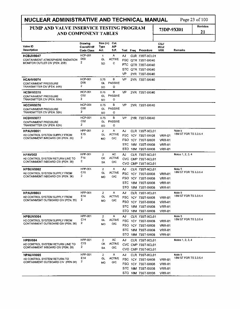
NUCLEAR ADMINISTRATIVE AND TECHNICAL MANUAL Page 23 of 100RevisionPUMP AND VALVE INSERVICE TESTING PROGRAM 73DP-9XI01 21
AND COMPONENT TABLESr 21
Drawing Size (in) Cat. CSJ/Valve ID Coord/Sht# Type A/P ROJIDescription Code Class Act. S.P. Test Freq Procedure VRR Remarks
HCBUVO047 HCP-001 1 A AJ CLR 73ST-9CL01
CONTAINMENT ATMOSPHERE RADIATION D03 GL ACTIVE FSC QTR 73ST-9XI40MONITOR OUTLET CIV (PEN. 25B) 2 so C FTC QTR 73ST-9XI40
STC QTR 73ST-9XI40
VP 2YR 73ST-9XI40
HCAHV0074 HCP-001 0.75 B VP 2YR 73ST-9XI40
CONTAINMENT PRESSURE D08 GL PASSIVETRANSMITTER CIV (PEN. 54A) 2 so 0
HCBHV0075 HCP-001 0.75 B VP 2YR 73ST-9XI40
CONTAINMENT PRESSURE C02 GL PASSIVETRANSMITTER CIV (PEN. 55A) 2 so 0
HCCHV0076 HCP-001 0.75 B VP 2YR 73ST-9X140
CONTAINMENT PRESSURE C08 GL PASSIVETRANSMITTER CIV (PEN. 32A) 2 so 0
HCDHV0077 HCP-001 0.75 B VP 2YR 73ST-9XI40
CONTAINMENT PRESSURE C02 GL PASSIVETRANSMITTER CIV (PEN. 62A) 2 so 0
HPAUVO001 HPP-001 2 A AJ CLR 73ST-9CLO1 Note 5
H2 CONTROL SYSTEM SUPPLY FROM E15 GL ACTIVE FSC ICY 73ST-9XI08 VRR-01 18M ST FOR TS 3.3.5.4
CONTAINMENT INBOARD CIV (PEN. 35) 2 MO O/C FSO iCY 73ST-9X10⁸ VRR-01
STC 18M 73ST-9XI08 VRR-01
STO 18M 73ST-9XI08 VRR-01
HPAV002 HPP-001 2 AC AJ CLR 73ST-9CLO1 Notes 1, 2, 3, 4
H2 CONTROL SYSTEM RETURN LINE TO F15 CK ACTIVE CVC CMP 73ST-9CLO1CONTAINMENT INBOARD CIV (PEN. 38) 2 SA O/C CVO CMP 73ST-9CLO1
HPBUVO002 HPP-001 2 A AJ CLR 73ST-9CLO1 Note 5
H2 CONTROL SYSTEM SUPPLY FROM C15 GL ACTIVE FSC 1CY 73ST-9XI08 VRR-01 18M ST FOR TS 3.3.5.4
CONTAINMENT INBOARD CIV (PEN. 36) 2 MO O/C FSO iCY 73ST-9XI08 VRR-01
STC 18M 73ST-9XI08 VRR-01
STO 18M 73ST-9XI08 VRR-01
HPAUVO003 HPP-001 2 A AJ CLR 73ST-9CLO1 Note 5
H2 CONTROL SYSTEM SUPPLY FROM E14 GL ACTIVE FSC iCY 73ST-9XI08 VRR-01 18M ST FOR TS 3.3.5.4
CONTAINMENT OUTBOARD CIV (PEN. 35) 2 MO O/C FSO ICY 73ST-9XI08 VRR-01
STC 18M 73ST-9XI08 VRR-01
STO 18M 73ST-9XI08 VRR-01
HPBUVO004 HPP-001 2 A AJ CLR 73ST-9CLO1 Note 5
H2 CONTROL SYSTEM SUPPLY FROM C14 GL ACTIVE FSC iCY 73ST-9XI08 VRR-01 18M ST FOR TS 3.3.5.4
CONTAINMENT OUTBOARD CIV (PEN. 36) 2 MO O/C FSO 1CY 73ST-9XI08 VRR-01
STC 18M 73ST-9XI08 VRR-01
STO 18M 73ST-9XI08 VRR-01
HPBV004 HPP-001 2 AC AJ CLR 73ST-9CLO1 Notes 1,2, 3, 4
H2 CONTROL SYSTEM RETURN LINE TO C15 CK ACTIVE CVC CMP 73ST-9CLO1CONTAINMENT INBOARD CIV (PEN. 39) 2 SA O/C CVO OMP 73ST-9CLO1
HPAUVO005 HPP-001 2 A AJ CLR 73ST-9CLO1 Note 5
H2 CONTROL SYSTEM RETURN TO E14 GL ACTIVE FSC ICY 73ST-9XI08 VRR-01 18M ST FOR TS 3.3.5.4
CONTAINMENT OUTBOARD CIV (PEN 38) 2 MO O/C FSO 1CY 73ST-9XI08 VRR-01
STC 18M 73ST-9XI08 VRR-01STO 18M 73ST-9XI08 VRR-01

NUCLEAR ADMINISTRATIVE AND TECHNICAL MANUAL Page 24 of 100PUMP AND VALVE INSERVICE TESTING PROGRAM Revision
AND COMPONENT TABLESr 21
Drawing Size (in) Cat. CSJ/Valve ID Coord/Sht# Type A/P ROJIDescription Code Class Act. S.P. Test Freq Procedure VRR Remarks
HPBUVO006 HPP-001 2 A AJ CLR 73ST-9CLO1 Note 5
H2 CONTROL SYSTEM RETURN TO C14 GL ACTIVE FSC 1CY 73ST-9XI08 VRR-01 18M ST FORTS 3.3.5.4
CONTAINMENT OUTBOARD CIV (PEN. 39) 2 MO O/C FSO 1CY 73ST-9XI08 VRR-01
STC 18M 73ST-9X10⁸ VRR-01
STO 18M 73ST-9X10⁸ VRR-01
HPAHV0007A HPP-001 1 A AJ CLR 73ST-9CLO1
POST-LOCA H2 MONITOR INLET CIV (PEN. F14 GL ACTIVE FSC QTR 73ST-9XI0835) 2 s0 0/C FSO QTR 73ST-9XI08
FTC QTR 73ST-9XI08
STC QTR 73ST-9XI08
STO QTR 73ST-9XI08
VP 2YR 73ST-9XI08
HPAHV0007B HPP-001 1 A AJ CLR 73ST-9CLO1
POST-LOCA H2 MONITOR OUTLET CIV G14 GL ACTIVE FSC QTR 73ST-9XI08(PEN. 38) 2 so O/C FSO QTR 73ST-9XI08
FTC QTR 73ST-9XI08
STC QTR 73ST-9XI08
STO QTR 73ST-9XI08
VP 2YR 73ST-9XI08
HPBHV0008A HPP-001 1 A AJ CLR 73ST-9CLO1
POST-LOCA H2 MONITOR INLET CIV (PEN. C13 GL ACTIVE FSC QTR 73ST-9XI0836) 2 so O/C FSO QTR 73ST-9XI08
FTC QTR 73ST-9XI08
STC QTR 73ST-9XI08
STO QTR 73ST-9XI08
VP 2YR 73ST-9XI08
HPBHV0008B HPP-001 1 A AJ CLR 73ST-9CLO1
POST-LOCA H2 MONITOR OUTLET CIV B14 GL ACTIVE FSC QTR 73ST-9XI08(PEN. 39) 2 so O/C FSO QTR 73ST-9XI08
FTC QTR 73ST-9XI08
STC QTR 73ST-9XI08
STO QTR 73ST-9XI08
VP 2YR 73ST-9XI08
HPAUVO023 HPP-001 0.5 A AJ CLR 73ST-9CLO1 Valve size is 1" in Units 2 and 3.
CONTAINMENT H2 MONITORING SYSTEM G14 GL ACTIVE FSC QTR 73ST-9X10⁸RETURN FROM PASS OUTBOARD CIV 2 so C(PEN 38)FTC QTR 73ST-9XI08(PEN. 38)
STC QTR 73ST-9XI08VP 2YR 73ST-9XI08
HPAUVO024 HPP-001 0.5 A AJ CLR 73ST-9CLO1 Valve size is 1" in Units 2 and 3
CONTAINMENT H2 MONITORING SYSTEM F12 GL ACTIVE FSC QTR 73ST-9XI08TO PASS CIV (PEN. 35) 2 so C FTC QTR 73ST-9XI08
STC QTR 73ST-9Xl08
VP 2YR 73ST-9XI08
IAAUVO002 IAP-003 2 A AJ CLR 73ST-9CLO1
INSTRUMENT AIR SUPPLY OUTSIDE G07 GL ACTIVE FSC CSD 73ST-9XI23 CSJ-06CONTAINMENT ISOLATION VALVE (PEN. 2 so C FTC CSD 73ST-9XI23 CSJ-0631)
STC CSD 73ST-9XI23 CSJ-06VP 2YR 73ST-9XI23

NUCLEAR ADMINISTRATIVE AND TECHNICAL MANUAL Page 25 of 100
PUMP AND VALVE INSERVICE TESTING PROGRAM 73DP-9XI01 Revision
AND COMPONENT TABLES 1 21
Drawing Size (in) Cat. CSJ/Valve ID Coord/Sht# Type A/P ROJ/Description Code Class Act.. S.P. Test Freq Procedure VRR Remarks
IAEV021 IAP-003 2 AC AJ CLR 73ST-9CLO1 Notes 1,2, 3, 4
INSTRUMENT AIR SUPPLY INSIDE G05 CK ACTIVE BDO CMP 40DP-90P05CONTAINMENT ISOLATION VALVE (PEN. 2 SA C31) CVC CMP 73ST-9CL01
IAEV072 IAP-002 3 A AJ CLR 73ST-9CL01BREATHING AIR CONTAINMENT G09 GL PASSIVEISOLATION VALVE (PEN. 59) 2 MA C
IAEV073 IAP-002 3 AC AJ CLR 73ST-9CLO1 Notes 1, 2, 3
BREATHING AIR SUPPLY INSIDE H07 CK PASSIVECONTAINMENT ISOLATION VALVE (PEN. 2 SA C59)
NCEV118 NCP-003 10 AC AJ CLR 73ST-9CLO1 Notes 1,2, 3, 4
NUCLEAR COOLING WATER SUPPLY TO E06 CK ACTIVE BDO CMP 40DP-90P05RCP COOLER INBOARD CIV (PEN. 33) 2 SA C CVC CMP 73ST-gCLOl
NCAHCV0244 NCP-002 10 B FSC 2YR 73ST-9XI44 Augmented
NUCLEAR COOLING WATER TO SPENT B04 BF ACTIVEFUEL POOL HEAT EXCHANGER 3 MA CISOLATION VALVE
NCBHCV0245 NCP-002 10 B FSC 2YR 73ST-9XI45 Augmented
NUCLEAR COOLING WATER TO SPENT B04 BF ACTIVEFUEL POOL HEAT EXCHANGER 3 MA CISOLATION VALVE
NCAPSV0250 NCP-002 1 C SV 10Y 73ST-9ZZ20 Thermal Relief Valve
FUEL POOL COOLING HEAT EXCHANGER E02 SV ACTIVERELIEF VALVE 3 SA O/C
NCBPSV0251 NCP-002 1 C SV 10Y 73ST-9ZZ20 Thermal Relief Valve
FUEL POOL COOLING HEAT EXCHANGER D02 SV ACTIVERELIEF VALVE 3 SA O/C
NCAHCV0258 NCP-002 10 B FSC 2YR 73ST-9X144 Augmented
NUCLEAR COOLING WATER TO SPENT C04 BF ACTIVEFUEL POOL HEAT EXCHANGER 3 MA CISOLATION VALVE
NCBHCV0259 NCP-002 10 B FSC 2YR 73ST-9X145 Augmented
NUCLEAR COOLING WATER TO SPENT B04 BF ACTIVEFUEL POOL HEAT EXCHANGER 3 MA CISOLATION VALVE
NCBUV0401 NCP-003 10 A AJ CLR 73ST-9CL01 Note 5
NUCLEAR COOLING WATER SUPPLY TO E07 BF ACTIVE FSC 1CY 73ST-9X]23 VRR-01 18M ST FOR TS 3.3.5.4
RCP COOLER OUTBOARD CIV (PEN. 33) 2 MO C STC 18M 73ST-9X]23 VRR-01
NCAUV0402 NCP-003 10 A AJ CLR 73ST-9CLO1 Note 5
NUCLEAR COOLING WATER SUPPLY TO F07 BF ACTIVE FSC 1CY 73ST-9XI23 VRR-01 18M ST FOR TS 3.3.5.4
RCP COOLER OUTBOARD CIV (PEN. 34) 2 MO C STC 18M 73ST-9XI23 VRR-01
NCBUV0403 NCP-003 10 A AJ CLR 73ST-9CLO1 Note 5
NUCLEAR COOLING WATER SUPPLY TO F06 BF ACTIVE FSC 1CY 73ST-9XI23 VRR-01 18M ST FOR TS 3.3.5.4
RCP COOLER INBOARD CIV (PEN. 34) 2 MO C STC 18M 73ST-9XI23 VRR-01
NCEPSV0614 NCP-003 6 C SV 10Y 73ST-9ZZ20 Augmented
NC CONTAINMENT ISOLATION VALVE E05 SV ACTIVERELIEF VALVE N SA 0
NCEPSV0615 NCP-003 6 C SV 10Y 73ST-9ZZ20 Augmented
NC CONTAINMENT ISOLATION VALVE E05 SV ACTIVERELIEF VALVE N SA 0
NCEPSV0617 NCP-003 0.75 AC AJ CLR 73ST-9CLO1
NC CONTAINMENT PENETRATION RELIEF E07 SV ACTIVE SV 10Y 73ST-9ZZ20VALVE (PEN 34) 2 SA O/C

NUCLEAR ADMINISTRATIVE AND TECHNICAL MANUAL Page 26 of 100
PUMP AND VALVE INSERVICE TESTING PROGRAM 73DP-9XI01 Revision
AND COMPONENT TABLES 21
Drawing Size (in) Cat. CSJ/Valve ID Coord/Sht# Type A/P ROJ/Description Code Class Act. S.P. Test Freq Procedure VRR Remarks
PCAV013 PCP-001 8 C CVC QTR 73ST-9PCO1 Notes 1,2, 3. Augmented.
SPENT FUEL POOL COOLING PUMP D15 CK ACTIVE CVO QTR 73ST-9PC01DISCHARGE CHECK VALVE 3 SA O/C
PCBV017 PCP-001 8 C CVC QTR 73ST-9PC01 Notes 1,2, 3. Augmented.
SPENT FUEL POOL COOLING PUMP B15 CK ACTIVE CVO QTR 73ST-9PCO1DISCHARGE CHECK VALVE 3 SA O/C
PCAPSVO035 PCP-001 1 C SV 10Y 73ST-9ZZ20 Thermal Relief Valve
SPENT FUEL POOL COOLING HEAT E13 SV ACTIVEEXCHANGER PRESSURE RELIEF VALVE 3 SA O/C
PCBPSVO036 PCP-001 1 C SV 10Y 73ST-9ZZ20 Augmented
SPENT FUEL POOL COOLING HEAT B13 SV ACTIVEEXCHANGER PRESSURE RELIEF VALVE 3 SA O/C
PCEV070 PCP-001 4 A AJ CLR 73ST-9CLO1
REFUELING POOL PURIFICATION. El0 GA PASSIVERETURN CONTAINMENT ISOLATION 2 MA CVALVE (PEN 50)
PCEV071 PCP-001 4 A AJ CLR 73ST-9CLO1
REFUELING POOL PURIFICATION E09 GA PASSIVERETURN CONTAINMENT ISOLATION 2 MA CVALVE (PEN 50)
PCEV075 PCP-001 4 A AJ CLR 73ST-9CLO1REFUELING POOL PURIFICATION SUPPLY G06 GA PASSIVECONTAINMENT ISOLATION VALVE (PEN 2 MA C51)
PCEV076 PCP-001 4 A AJ CLR 73ST-9CLO1REFUELING POOL PURIFICATION SUPPLY G05 GA PASSIVECONTAINMENT ISOLATION VALVE (PEN 2 MA C51)
PCNV215 CHP-002 3 B FSC 2YR 73ST-9XI44
RWTTO SPENT FUEL POOL MANUAL All DI ACTIVE FSO 2YR 73ST-9XI44ISOLATION VALVE 3 MA O/C
RCAHV0101 RCP-001 1 B FSC CSD 73ST-9XI24 CSJ-07REACTOR VESSEL HEAD VENT VALVE G15 GL ACTIVE FSO CSD 73ST-9XI24 CSJ-07
2 so O/CFTC CSD 73ST-9XI24 CSJ-07
STC CSD 73ST-9XI24 CSJ-07STO CSD 73ST-9XI24 CSJ-07
VP 2YR 73ST-9XI24
RCBHV0102 RCP-001 1 B FSC CSD 73ST-9X124 CSJ-07REACTOR VESSEL HEAD VENT VALVE G15 GL ACTIVE FSO CSD 73ST-9XI24 CSJ-07
2 so O/C FTC CSD 73ST-9X124 CSJ-07
STC CSD 73ST-9X124 CSJ-07
STO CSD 73ST-9XI24 CSJ-07
VP 2YR 73ST-9XI24
RCAHV0103 RCP-001 1 B FSC CSD 73ST-9XI24 CSJ-07PRESSURIZER VENT VALVE G14 GL ACTIVE FSO CSD 73ST-9XI24 CSJ-07
2 so O/C FTC CSD 73ST-9X124 CSJ-07
STC CSD 73ST-9X124 CSJ-07
STO CSD 73ST-9XI24 CSJ-07
VP 2YR 73ST-9XI24

NUCLEAR ADMINISTRATIVE AND TECHNICAL MANUAL Page 27 of 100
PUMP AND VALVE INSERVICE TESTING PROGRAM 73DP-9XI01 Revision
AND COMPONENT TABLES 21
Drawing Size (in) Cat. CSJ/Valve ID Coord/Sht# Type A/P ROJ/Description Code Class Act. S.P. Test Freq Procedure VRR Remarks
RCBHV0105 RCP-001 1 B FSC CSD 73ST-9XI24 CSJ-07PRESSURIZER/REACTOR VESSEL HEAD G13 GL ACTIVE FSO CSD 73ST-9XI24 CSJ-07VENT VALVE TO REACTOR DRAIN TANK 2 so O/C FTC CSD 73ST-9XI24 CSJ-07
STC CSD 73ST-9XI24 CSJ-07STO CSD 73ST-9XI24 CSJ-07
VP 2YR 73ST-9XI24
RCAHV0106 RCP-001 1 B FSC CSD 73ST-9XI24 CSJ-07PRESSURIZER/REACTOR VESSEL HEAD G13 GL ACTIVE FSO CSD 73ST-9X124 CSJ-07VENT VALVE TO CONTAINMENT 2 so O/C FTC CSD 73ST-9XI24 CSJ-07
STC CSD 73ST-9XI24 CSJ-07STO CSD 73ST-9X124 CSJ-07VP 2YR 73ST-9XI24
RCBHV0108 RCP-001 1 B FSC CSD 73ST-9XI24 CSJ-07PRESSURIZER VENT VALVE G13 GL ACTIVE FSO CSD 73ST-9XI24 CSJ-07
1 so O/C FTC CSD 73ST-9XI24 CSJ-07
STC CSD 73ST-9XI24 CSJ-07
STO CSD 73ST-9XI24 CSJ-07
VP 2YR 73ST-9X124
RCBHV0109 RCP-001 1 B FSC CSD 73ST-9XI24 CSJ-07PRESSURIZER VENT VALVE G13 GL ACTIVE FSO CSD 73ST-9XI24 CSJ-07
1 so O/C FTC CSD 73ST-9XI24 CSJ-07
STC CSD 73ST-9XI24 CSJ-07
STO CSD 73ST-9XI24 CSJ-07
VP 2YR 73ST-9XI24
RCEPSV0200 RCP-001 6 C SV RFO 73ST-9ZZ18 Tested each refueling (ref. RCTSPRESSURIZER SAFETY VALVE F12 SV ACTIVE 040634)
1 SA O/C
RCEPSV0201 RCP-001 6 C SV RFO 73ST-9ZZ18 Tested each refueling (ref. RCTSPRESSURIZER SAFETY VALVE F12 SV ACTIVE 040634)
1 SA O/C
RCEPSV0202 RCP-001 6 C SV RFO 73ST-9ZZ18 Tested each refueling (ref. RCTSPRESSURIZER SAFETY VALVE F12 SV ACTIVE 040634)
1 SA O/C
RCEPSV0203 RCP-001 6 C SV RFO 73ST-9ZZ18 Tested each refueling (ref. RCTSPRESSURIZER SAFETY VALVE F12 SV ACTIVE 040634)
1 SA O/C
RDAV020 RDP-002 sht 2 4 C CVC CMP 73ST-9ZZ25 Notes 1,3, 4CONTAINMENT SPRAY PUMP ROOM B14 CK ACTIVE CVO CMP 73ST-9ZZ25 Disassembly and InspectionFLOOR DRAIN CHECK VALVE TO ESF 3 SA O/CSUMP
RDAV021 RDP-002 sht 2 4 C CVC CMP 73ST-9ZZ25 Notes 1, 3, 4HPSI PUMP ROOM FLOOR DRAIN CHECK B05 CK ACTIVE CVO CMP 73ST-9ZZ25 Disassembly and InspectionVALVE TO ESF SUMP 3 SA O/C
RDAV022 RDP-002 sht 2 4 C CVC CMP 73ST-9ZZ25 Notes 1, 3, 4LPSI PUMP ROOM FLOOR DRAIN CHECK B14 CK ACTIVE CVO CMP 73ST-9ZZ25 Disassembly and InspectionVALVE TO ESF SUMP 3 SA O/C
RDAUVO023 RDP-001 3 A AJ CLR 73ST-9CLO1 Note 5QTR FS FOR PRN/RACONTAINMENT RADWASTE SUMP G04 GA ACTIVE FSC QTR 73ST-9XI07 VRR-01 18M ST FOR TS 3.3.5.4OUTLET INBOARD CIV (PEN. 9) 2 MO C STC 18M 73ST-9XI07 VRR-01

NUCLEAR ADMINISTRATIVE AND TECHNICAL MANUAL Page 28 of 100
PUMP AND VALVE INSERVICE TESTING PROGRAM 73DP-9X101 Revision
AND COMPONENT TABLES 21
Drawing Size (in) Cat. CSJ/Valve ID Coord/Sht# Type A/P ROJ/Description Code Class Act. S.P. Test Freq Procedure VRR Remarks
RDBUVO024 RDP-001 3 A AJ CLR 73ST-9CLO1
CONTAINMENT RADWASTE SUMP G04 GA ACTIVE FSC QTR 73ST-9XI07OUTLET OUTBOARD CIV (PEN. 9) 2 AO C FTC QTR 73ST-9XI07
STC QTR 73ST-9XI07
VP 2YR 73ST-9XI07
RDBV040 RDP-002 sht 3 4 C CVC CMP 73ST-9ZZ25 Notes 1,3, 4
CONTAINMENT SPRAY PUMP ROOM B05 CK ACTIVE CVO CMP 73ST-9ZZ25 Disassembly and Inspection
FLOOR DRAIN CHECK VALVE TO ESF 3 SA O/CSUMP
RDBV041 RDP-002 sht 3 4 C CVC CMP 73ST-9ZZ25 Notes 1,3, 4
HPSI PUMP ROOM FLOOR DRAIN CHECK B05 CK ACTIVE CVO CMP 73ST-9ZZ25 Disassembly and Inspection
VALVE TO ESF SUMP 3 SA O/C
RDBV042 RDP-002 sht 3 4 C CVC CMP 73ST-9ZZ25 Notes 1,3, 4
LPSI PUMP ROOM FLOOR DRAIN CHECK B05 CK ACTIVE CVO CMP 73ST-97725 Disassembly and Inspection
VALVE TO ESF SUMP 3 SA O/C
RDAV203 RDP-002 sht 3 4 C CVC CMP 73ST-9ZZ25 Disassembly and Inspection
AUXILIARY FEEDWATER PUMP ROOM G04 CK ACTIVE CVO CMP 73ST-9ZZ25TRAIN A FLOOR DRAIN CHECK VALVE TO N SA O/CNON-ESF SUMP
RDBV204 RDP-002 sht 3 4 C CVC CMP 73ST-9ZZ25 Disassembly and Inspection
AUXILIARY FEEDWATER PUMP ROOM F03 CK ACTIVE CVO CMP 73ST-9ZZ25TRAIN B FLOOR DRAIN CHECK VALVE TO N SA O/CNON-ESF SUMP
RDBUV0407 RDP-001 0.5 A AJ CLR 73ST-9CLO1CONTAINMENT RADWASTE SUMP G04 GL ACTIVE FSC QTR 73ST-9XI07OUTLET TO POST ACCIDENT SAMPLING 2 so CCIV (PEN. 9) FTC QTR 73ST-9XI07
STC QTR 73ST-9XI07
VP 2YR 73ST-9XI07
SGEV003 SGP-002 24 C BDO CMP Normal Ops Notes 1,2, 3, 4
ECONOMIZER FEEDWATER LINE CHECK El0 CK ACTIVE CVC CMP 73ST-9XI32VALVE(PEN.8) 2 SA C
SGEV005 SGP-002 24 C BDO CMP Normal Ops Notes 1,2, 3, 4
ECONOMIZER FEEDWATER LINE CHECK A10 CK ACTIVE CVC CMP 73ST-9XI32VALVE (PEN. 10) 2 SA C
SGEV006 SGP-002 24 C BDO CMP Normal Ops Notes 1,2, 3, 4
ECONOMIZER FEEDWATER LINE CHECK A10 CK ACTIVE CVC CMP 73ST-9XI32VALVE (PEN. 10) 2 SA C
SGEV007 SGP-002 24 C BDO CMP Normal Ops Notes 1, 2, 3, 4
ECONOMIZER FEEDWATER LINE CHECK El0 CK ACTIVE CVC CMP 73ST-9XI32VALVE (PEN. 8) 2 SA C
SGEVA19 VM M234A-14 0.5 AC BDO CMP 73ST-9SGO1 Notes 1,2, 3, 4MSIV 170 INSTRUMENT AIR CHECK VALVE NA CK ACTIVE CVC CMP 73ST-9SGO1
2 SA C LT 2YR 73ST-9SGO1
SGEVA20 VM M234A-14 0.5 AC BDO CMP 73ST-9SGO1 Notes 1,2, 3, 4
MSIV 170 INSTRUMENT AIR CHECK VALVE NA CK ACTIVE CVC CMP 73ST-9SGO12 SA C LT 2YR 73ST-9SGO1
SGEVA21 VM M234A-14 0.5 AC BDO CMP 73ST-9SGO1 Notes 1,2, 3, 4
MSIV 180 INSTRUMENT AIR CHECK NA CK ACTIVE CVC CMP 73ST-9SGO1VALVE 2 SA C LT 2YR 73ST-9SGO1
SGEVA22 VM M234A-14 0.5 AC BDO CMP 73ST-9SGO1 Notes 1,2, 3, 4
MSIV 180 INSTRUMENT AIR CHECK NA CK ACTIVE CVC CMP 73ST-9SGO1VALVE 2 SA C LT 2YR 73ST-9SGO1
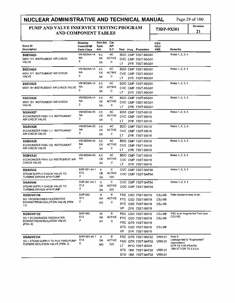
NUCLEAR ADMINISTRATIVE AND TECHNICAL MANUAL Page 29 of 100
PUMP AND VALVE INSERVICE TESTING PROGRAM 73DP-9XI01 Revision
AND COMPONENT TABLES 21
Drawing Size (in) Cat. CSJIValve ID Coord/Sht# Type A/P ROJ/Description Code Class Act. S.P. Test Freq Procedure VRR Remarks
SGEVA23 VM M234A-14 0.5 AC BDO CMP 73ST-9SGO1 Notes 1,2, 3, 4
MSIV 171 INSTRUMENT AIR CHECK NA CK ACTIVE CVC CMP 73ST-9SGO1VALVE 2 SA C LT 2YR 73ST-9SGO1
SGEVA24 VM M234A-14 0.5 AC BDO CMP 73ST-9SGO1 Notes 1,2, 3, 4
MSIV 171 INSTRUMENT AIR CHECK NA CK ACTIVE CVC CMP 73ST-9SGO1VALVE 2 SA C LT 2YR 73ST-9SGO1
SGEVA25 VM M234A-14 0.5 AC BDO CMP 73ST-9SGO1 Notes 1,2, 3, 4
MSIV 181 INSTRUMENT AIR CHECK VALVE NA CK ACTIVE CVC CMP 73ST-9SGO12 SA C LT 2YR 73ST-9SGO1
SGEVA26 VM M234A-14 0.5 AC BDO CMP 73ST-9SGO1 Notes 1,2, 3, 4
MSIV181 INSTRUMENT AIR CHECK NA CK ACTIVE CVC CMP 73ST-9SGO1VALVE 2 SA C LT 2YR 73ST-9SGO1
SGAVA27 VM M234A-55 0.5 AC BDO CMP 73ST-9XI16 Notes 1,2, 3, 4
ECONOMIZER FWIV 174 INSTRUMENT NA CK ACTIVE CVC CMP 73ST-9XI16AIR CHECK VALVE 2 SA C LT 2YR 73ST-9XI 16
SGAVA28 VM M234A-55 0.5 AC BDO CMP 73ST-9XI16 Notes 1,2, 3, 4
ECONOMIZER FWIV 177 INSTRUMENT NA CK ACTIVE CVC CMP 73ST-9XI16AIR CHECK VALVE 2 SA C LT 2YR 73ST-9XI16
SGBVA29 VM M234A-55 0.5 AC BDO CMP 73ST-9XI16 Notes 1,2, 3, 4
ECONOMIZER FWIV 132 INSTRUMENT NA CK ACTIVE CVC CMP 73ST-9XI16AIR CHECK VALVE 2 SA C LT 2YR 73ST-9XI16
SGBVA30 VM M234A-55 0.5 AC BDO CMP 73ST-9XI16 Notes 1,2, 3, 4
ECONOMIZER FWIV 137 INSTRUMENT AIR NA CK ACTIVE CVC CMP 73ST-9XI16CHECK VALVE SA C LT 2YR 73ST-9XI16
SGAV043 SGP-001 sht 1 6 C CVC CMP 73ST-9AF04 Notes 1,2, 3, 4
STEAM SUPPLY CHECK VALVE TO E12 CK ACTIVE CVO CMP 73ST-9AF04TURBINE-DRIVEN AFW PUMP 3 SA O/C
SGAV044 SGP-001 sht 1 6 C CVC CMP 73ST-9AF04 Notes 1,2, 3, 4
STEAM SUPPLY CHECK VALVE TO C12 CK ACTIVE CVO CMP 73ST-9AF04TURBINE-DRIVEN AFW PUMP 3 SA O/C
SGBUVO130 SGP-002 8 B FSC CSD 73ST-9XI19 CSJ-08 Fails closed on loss of air.
SG 1 DOWNCOMER FEEDWATER Gl1 GA ACTIVE FTC CSD 73ST-9XI19 CSJ-08DOWNSTREAM ISOLATION VALVE (PEN. 2 AO C11)STC CSD 73ST-9XI19 CSJ-08
VP 2YR 73ST-9XI19
SGBUVO132 SGP-002 24 B FSC CSD 73ST-9XI16 CSJ-08 PSC is an Augmented Test (see
SG 1 ECONOMIZER FEEDWATER E12 GA ACTIVE FTC CSD 73ST-9XI16 CSJ-08 CSJ-08)
DOWNSTREAM ISOLATION VALVE 2 HY C(PEN. 8) PSC QTR 73ST-9XI16
STC CSD 73ST-9XI16 CSJ-08
VP 2YR 73ST-9XI16
SGAUVO134 SGP-001 sht 1 6 B FSC QTR 73ST-9AF02 VRR-01 Note 5
SG 1 STEAM SUPPLY TO AUX FEED PUMP E14 GA ACTIVE FSO QTR 73ST-9AF02 VRR-01 Leakage test is 'Augmented
TRIEIOAINVALVE (PEN. 2) 2 M O0/C requirement.TURBINE ISOLATION LT RFO 73ST-9XI34 QTR FS FOR PRA/RA
STC 18M 73ST-9AF02 VRR-01 18M ST FOR TS 3.3.5.4
STO 18M 73ST-9AF02 VRR-01

NUCLEAR ADMINISTRATIVE AND TECHNICAL MANUAL Page 30 of 100PUMP AND VALVE INSERVICE TESTING PROGRAM 73DP-9XI01 Revision
AND COMPONENT TABLES 21
Drawing Size (in) Cat. CSj/Valve ID Coord/Sht# Type A/P ROJ/Description Code Class Act. S.P. Test Freq Procedure VRR Remarks
SGBUVO134A SGP-001 sht 1 1 B FSC QTR 73ST-9AF02 Leakage test is "Augmented"
TDAFW PUMP STEAM SUPPLY WARM-UP E13 GL ACTIVE FSO QTR 73ST-9AF02 requirement.
LINE ISOLATION VALVE 2 SO O/C(PEN.2) FTC QTR 73ST-9AF02
LT RFO 73ST-9XI34
STC QTR 73ST-9AF02STO QTR 73ST-9AF02
VP 2YR 73ST-9AF02
SGBUVO135 SGP-002 8 B FSC CSD 73ST-9XI 19 CSJ-08 Fails closed on loss of air only
SG 2 DOWNCOMER FEEDWATER Cll GA ACTIVE FTC CSD 73ST-9XI19 CSJ-08DOWNSTREAM ISOLATION VALVE (PEN. 2 AO C STO CSD 73ST-9X119 CSJ-0812)
VP 2YR 73ST-9XI19
SGBUV0137 SGP-002 24 B FSC CSD 73ST-9XI16 CSJ-08 PSC is an Augmented Test (see
SG 2 ECONOMIZER FEEDWATER A12 GA ACTIVE FTC CSD 73ST-9XI16 CSJ-08 CSJ-08)
DOWNSTREAM ISOLATION VALVE 2 HY C(PEN 10)PSC QTR 73ST-9XI16(PEN. 10)
STC CSD 73ST-9XI16 CSJ-08
VP 2YR 73ST-9XI16
SGAUVO138 SGP-001 sht 1 6 B FSC QTR 73ST-9AF02 VRR-01 Note 5
SG 2 STEAM SUPPLYTO AUX FEED PUMP C13 GA ACTIVE FSO QTR 73ST-9AF02 VRR-01 Leakage test is"Augmented"
TURBINE ISOLATION VALVE (PEN. 3) 2 MO 0/C requirement.LT RFO 73ST-9XI34 QTR FS FOR PRA/RA
STC 18M 73ST-9AF02 VRR-01 18M ST FORTS 3.3.5.4
STO 18M 73ST-9AF02 VRR-01
SGAUVO138A SGP-001 sht 1 1 B FSC QTR 73ST-9AF02 Leakage test is "Augmented"
TDAFW PUMP STEAM SUPPLY WARM-UP C14 GL ACTIVE FSO QTR 73ST-9AF02 requirement.
LINE ISOLATION VALVE 2 so O/C(PEN. 3) FTC QTR 73ST-9AF02
LT RFO 73ST-9XI34
STC QTR 73ST-9AF02
STO QTR 73ST-9AF02
VP 2YR 73ST-9AF02
SGEUVO169 SGP-001 sht 1 4 B FSC QTR 73ST-9X101
MSIV BYPASS VALVE (PEN. 2) Dll GA ACTIVE FTC QTR 73ST-9X10¹² AO C STC QTR 73ST-9X101
VP 2YR 73ST-9X101
SGEUV0170 SGP-001 sht 1 28 B FSC CSD 73ST-9SGO1 CSJ-09 PSC is an Augmented Test (see
MAIN STEAM ISOLATION VALVE (PEN. 1) G10 GA ACTIVE FTC CSD 73ST-9SGO1 CSJ-09 CSJ-09)2 HY C PSC QTR 73ST-9SGO1
STC CSD 73ST-9SGO1 CSJ-09
VP 2YR 73ST-9SG01
SGEUVO171 SGP-001 sht 1 28 B FSC CSD 73ST-9SGO1 CSJ-09 PSC is an Augmented Test (see
MAIN STEAM ISOLATION VALVE (PEN. 3) D10 GA ACTIVE FTC CSD 73ST-9SGO1 CSJ-09 CSJ-09).2 HY C PSC QTR 73ST-9SGO1
STC CSD 73ST-9SGO1 CSJ-09
VP 2YR 73ST-9SGO1
SGAUVO172 SGP-002 8 B FSC CSD 73ST-9X1 19 CSJ-08 Fails closed on loss of air only
SG 1 DOWNCOMER FEEDWATER G12 GA ACTIVE FTC CSD 73ST-9X119 CSJ-08UPSTREAM ISOLATION VALVE 2 AO C(PEN. 11) STC CSD 73ST-9XI19 CSJ-08
VP 2YR 73ST-9XI19

NUCLEAR ADMINISTRATIVE AND TECHNICAL MANUAL Page 31 of 100
PUMP AND VALVE INSERVICE TESTING PROGRAM 73DP-9XI01 Revision
AND COMPONENT TABLES 21
Drawing Size (in) Cat. CSJIValve ID Coord/Sht# Type A/P ROJ/Description Code Class Act. S.P. Test Freq Procedure VRR Remarks
SGAUVO174 SGP-002 24 B FSC CSD 73ST-9X116 CSJ-08 PSC is an Augmented Test (see
SG 1 ECONOMIZER FEEDWATER E12 GA ACTIVE FTC CSD 73ST-9XI16 CSJ-08 CSJ-08)
UPSTREAM ISOLATION VALVE 2 HY C PSC QTR 73ST-9X116(PEN. 8)
STC CSD 73ST-9XI16 CSJ-08
VP 2YR 73ST-9XI16
SGAUVO175 SGP-002 8 B FSC CSD 73ST-9XI19 CSJ-08 Fails closed on loss of air only
SG 2 DOWNCOMER FEEDWATER C12 GA ACTIVE FTC CSD 73ST-9XI19 CSJ-08UPSTREAM ISOLATION VALVE 2 AO C(PEN. 12) STC CSD 73ST-9XI19 CSJ-08
VP 2YR 73ST-9XI19
SGAUVO177 SGP-002 24 B FSC CSD 73ST-9XI16 CSJ-08 PSC is an Augmented Test (see
SG 2 ECONOMIZER FEEDWATER A12 GA ACTIVE FTC CSD 73ST-9XI16 CSJ-08 CSJ-08)
UPSTREAM ISOLATION VALVE 2 HY C(PEN. 10) PSC QTR 73ST-9XI16
STC CSD 73ST-9XI16 CSJ-08VP 2YR 73ST-9X116
SGBHV0178 SGP-001 sht 2 12 B FSC QTR 73ST-9X120STEAM GENERATOR ATMOSPHERIC E02 GL ACTIVE FSO QTR 73ST-9X120DUMP VALVE (ADV) (PEN. 2) 2 AO O/C FTC QTR 73ST-9XI20
STC QTR 73ST-9X120
STO QTR 73ST-9XI20
VP 2YR 73ST-9XI20
SGAHV0179 SGP-001 sht 2 12 B FSC QTR 73ST-9XI20STEAM GENERATOR ATMOSPHERIC B02 GL ACTIVE FSO QTR 73ST-9XI20DUMP VALVE (ADV) (PEN. 4) 2 AO O/C FTC QTR 73ST-9XI20
STC QTR 73ST-9XI20
STO QTR 73ST-9X120
VP 2YR 73ST-9XI20
SGEUVO180 SGP-001 sht 1 28 B FSC CSD 73ST-9SGO1 CSJ-09 PSC is an Augmented Test (see
MAIN STEAM ISOLATION VALVE (PEN. 2) Flo GA ACTIVE FTC CSD 73ST-9SGO1 CSJ-09 CSJ-09)2 HY C PSC QTR 73ST-9SG01
STC CSD 73ST-9SGO1 CSJ-09
VP 2YR 73ST-9SG01
SGEUV0181 SGP-001 sht 1 28 B FSC CSD 73ST-9SG01 CSJ-09 PSC is an Augmented Test (see
MAIN STEAM ISOLATION VALVE (PEN. 4) B10 GA ACTIVE FTC CSD 73ST-9SG01 CSJ-09 CSJ-09)2 HY C PSC QTR 73ST-9SGO1
STC CSD 73ST-9SGO1 CSJ-09
VP 2YR 73ST-9SG01
SGEUVO183 SGP-001 sht 1 4 B FSC QTR 73ST-9XI02
MSIV BYPASS VALVE (PEN. 3) Cll GA ACTIVE FTC QTR 73ST-9X10²² AO C STC QTR 73ST-9XI02
VP 2YR 73ST-9XI02
SGAHV0184 SGP-001 sht 2 12 B FSC QTR 73ST-9XI20STEAM GENERATOR ATMOSPHERIC G02 GL ACTIVE FSO QTR 73ST-9XI20DUMP VALVE (ADV) (PEN. 1) 2 AO O/C
FTC QTR 73ST-9X120STO QTR 73ST-9X120STO QTR 73ST-9X120
VP 2YR 73ST-9X120

NUCLEAR ADMINISTRATIVE AND TECHNICAL MANUAL Page 32 of 100
PUMP AND VALVE INSERVICE TESTING PROGRAM 73DP-9XI01 Revision
AND COMPONENT TABLES 21
Drawing Size (in) Cat. CSJ/Valve ID Coord/Sht# Type A/P ROJ/Description Code Class Act. S.P. Test Freq Procedure VRR Remarks
SGBHV0185 SGP-001 sht2 12 B FSC QTR 73ST-9XI20
STEAM GENERATOR ATMOSPHERIC D02 GL ACTIVE FSO QTR 73ST-9XI20DUMP VALVE (ADV) (PEN. 3) 2 AO O/C FTC QTR 73ST-9XI20
STC QTR 73ST-9XI20
STO QTR 73ST-9XI20
VP 2YR 73ST-9XI20
SGBHV0200 SGP-002 0.375 B FSC QTR 73ST-9XI01
CHEMICAL INJECTION ISOLATION VALVE Fll GL ACTIVE FTC QTR 73ST-9XI01(PEN. 11) 2 so C STC QTR 73ST-9XI01
VP 2YR 73ST-9X101
SGBHV0201 SGP-002 0.375 B FSC QTR 73ST-9XI02
CHEMICAL INJECTION ISOLATION VALVE Bl1 GL ACTIVE FTC QTR 73ST-9XI02(PEN. 12) 2 s0 C STC QTR 73ST-9X10²
VP 2YR 73ST-9XI02
SGAUV0204 SGP-002 0.5 B FSC QTR 73ST-9X101
SG 1 HOT LEG BLOWDOWN SAMPLE LINE F03 GL ACTIVE FTC QTR 73ST-9X101ISOLATION VALVE (PEN. 37B) 2 so C STC QTR 73ST-9XI01
VP 2YR 73ST-9X101
SGAUV0211 SGP-002 0.5 B FSC QTR 73ST-9XI01
SG 1 COLD LEG BLOWDOWN SAMPLE G03 GL ACTIVE FTC QTR 73ST-9XI01LINE ISOLATION VALVE (PEN. 37A) 2 so C STC QTR 73ST-9X101
VP 2YR 73ST-9XI01
SGBUV0219 SGP-002 0.5 B FSC QTR 73ST-9XI01
SG 1 HOT LEG BLOWDOWN SAMPLE LINE G03 GL ACTIVE FTC QTR 73ST-9XI01ISOLATION VALVE (PEN. 37B) 2 so C STC QTR 73ST-9X101
VP 2YR 73ST-9XI01
SGAUV0220 SGP-002 0.5 B FSC QTR 73ST-9XI01
SG 1 DOWNCOMER BLOWDOWN SAMPLE G06 GL ACTIVE FTC QTR 73ST-9XI01LINE ISOLATION VALVE (PEN. 49) 2 so C STC QTR 73ST-9XI01
VP 2YR 73ST-9X101
SGBUV0221 SGP-002 0.5 B FSC QTR 73ST-9X101
SG 1 DOWNCOMER BLOWDOWN SAMPLE G05 GL ACTIVE FTC QTR 73ST-9XI01LINE ISOLATION VALVE PEN. 49) 2 so C STC QTR 73ST-9X101
VP 2YR 73ST-9XI01
SGBUV0222 SGP-002 0.5 B FSC QTR 73ST-9XI02
SG 2 COLD LEG BLOWDOWN SAMPLE C04 GL ACTIVE FTC QTR 73ST-9X10²LINE ISOLATION VALVE (PEN. 63B) 2 so C STC QTR 73ST-9XI02
VP 2YR 73ST-9XI02
SGAUV0223 SGP-002 0.5 B FSC QTR 73ST-9XI02
SG 2 COLD LEG BLOWDOWN SAMPLE C03 GL ACTIVE FTC QTR 73ST-9XI02LINE ISOLATION VALVE (PEN. 63B) 2 so C STC QTR 73ST-9XI02
VP 2YR 73ST-9XI02
SGBUV0224 SGP-002 0.5 B FSC QTR 73ST-9XI02
SG 2 HOT LEG BLOWDOWN SAMPLE LINE D04 GL ACTIVE FTC QTR 73ST-9XI02ISOLATION VALVE (PEN. 63A) 2 so C STC QTR 73ST-9XI02
VP 2YR 73ST-9XI02
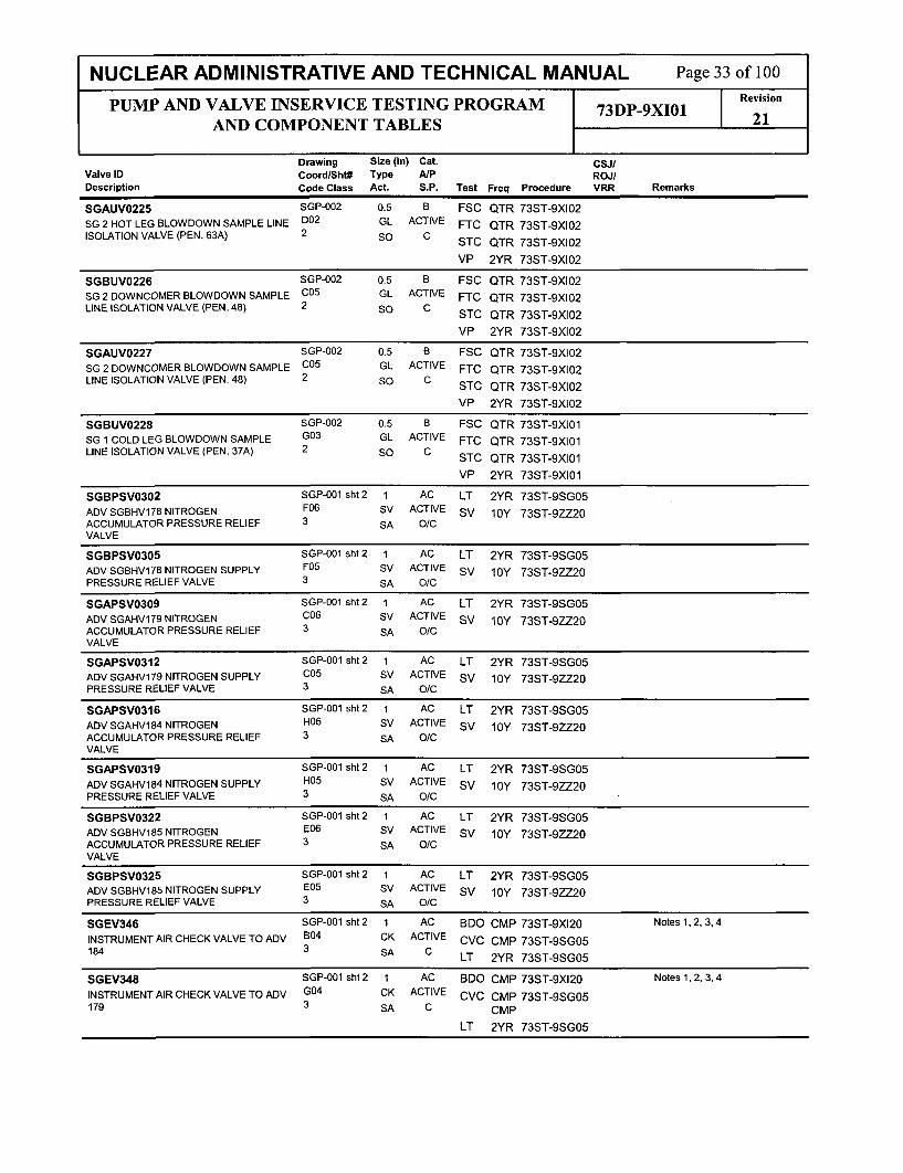
NUCLEAR ADMINISTRATIVE AND TECHNICAL MANUAL Page 33 of 100
PUMP AND VALVE INSERVICE TESTING PROGRAM 73DP-9XI01 Revision
AND COMPONENT TABLES 21
Drawing Size (in) Cat. CSJIValve ID Coord/Sht# Type A/P ROJ/Description Code Class Act. S.P. Test Freq Procedure VRR Remarks
SGAUV0225 SGP-002 0.5 B FSC QTR 73ST-9XI02SG 2 HOT LEG BLOWDOWN SAMPLE LINE D02 GL ACTIVE FTC QTR 73ST-9XI02ISOLATION VALVE (PEN. 63A) 2 SO C STC QTR 73ST-9X10²
VP 2YR 73ST-9X10²
SGBUV0226 SGP-002 0.5 B FSC QTR 73ST-9XI02SG 2 DOWNCOMER BLOWDOWN SAMPLE C05 GL ACTIVE FTC QTR 73ST-9XI02LINE ISOLATION VALVE (PEN. 48) 2 SO C STC QTR 73ST-9X10²
VP 2YR 73ST-9X10²
SGAUV0227 SGP-002 0.5 B FSC QTR 73ST-9XI02SG 2 DOWNCOMER BLOWDOWN SAMPLE C05 GL ACTIVE FTC QTR 73ST-9X10²LINE ISOLATION VALVE (PEN. 48) 2 SO C STC QTR 73ST-9XI02
VP 2YR 73ST-9XI02
SGBUV0228 SGP-002 0.5 B FSC QTR 73ST-9XI01SG 1 COLD LEG BLOWDOWN SAMPLE G03 GL ACTIVE FTC QTR 73ST-9XI01LINE ISOLATION VALVE (PEN. 37A) 2 so C STC QTR 73ST-9XI01
VP 2YR 73ST-9XI01
SGBPSV0302 SGP-001 sht 2 1 AC LT 2YR 73ST-9SG05ADV SGBHV178 NITROGEN F06 SV ACTIVE sv 10Y 73ST-9ZZ20ACCUMULATOR PRESSURE RELIEF 3 SA O/CVALVE
SGBPSV0305 SGP-001 sht 2 1 AC LT 2YR 73ST-9SG05ADV SGBHV178 NITROGEN SUPPLY F05 SV ACTIVE sv 10Y 73ST-9ZZ20PRESSURE RELIEF VALVE 3 SA O/C
SGAPSV0309 SGP-001 sht 2 1 AC LT 2YR 73ST-9SG05
ADV SGAHV179 NITROGEN C06 SV ACTIVE SV 10Y 73ST-9ZZ20ACCUMULATOR PRESSURE RELIEF 3 SA O/CVALVE
SGAPSV0312 SGP-001 sht 2 1 AC LT 2YR 73ST-9SG05ADV SGAHV179 NITROGEN SUPPLY C05 SV ACTIVE SV 10Y 73ST-9ZZ20PRESSURE RELIEF VALVE 3 SA O/C
SGAPSV0316 SGP-001 sht 2 1 AC LT 2YR 73ST-9SG05ADV SGAHVI84 NITROGEN H06 SV ACTIVE SV 10Y 73ST-9ZZ20ACCUMULATOR PRESSURE RELIEF 3 SA O/CVALVE
SGAPSV0319 SGP-001 sht 2 1 AC LT 2YR 73ST-9SG05
ADV SGAHV184 NITROGEN SUPPLY H05 SV ACTIVE SV 10Y 73ST-9ZZ20PRESSURE RELIEF VALVE 3 SA O/C
SGBPSV0322 SGP-001 sht 2 1 AC LT 2YR 73ST-9SG05
ADV SGBHV185 NITROGEN E06 SV ACTIVE SV 10Y 73ST-9ZZ20ACCUMULATOR PRESSURE RELIEF 3 SA O/CVALVE
SGBPSV0325 SGP-001 sht 2 1 AC LT 2YR 73ST-9SG05ADV SGBHV185 NITROGEN SUPPLY E05 SV ACTIVE SV 10Y 73ST-9ZZ20PRESSURE RELIEF VALVE 3 SA O/C
SGEV346 SGP-001 sht 2 1 AC BDO CMP 73ST-9XI20 Notes 1, 2, 3, 4
INSTRUMENT AIR CHECK VALVE TO ADV B04 CK ACTIVE CVC CMP 73ST-9SG05184 3 SA C LT 2YR 73ST-9SG05
SGEV348 SGP-001 sht 2 1 AC BDO CMP 73ST-9XI20 Notes 1, 2, 3, 4
INSTRUMENT AIR CHECK VALVE TO ADV G04 CK ACTIVE CVC CMP 73ST-9SG05179 3 SA C CMP
LT 2YR 73ST-9SG05

NUCLEAR ADMINISTRATIVE AND TECHNICAL MANUAL Page 34 of 100
PUMP AND VALVE INSERVICE TESTING PROGRAM 73DP-9XI01 Revision
AND COMPONENT TABLES 21
Drawing Size (in) Cat. CSJIValve ID Coord/Sht# Type A/P ROJ/Description Code Class Act. S.P. Test Freq Procedure VRR Remarks
SGEV357 SGP-001 sht 2 1 AC BDO CMP 73ST-9XI20 Notes 1,2, 3, 4
INSTRUMENT AIR CHECK VALVE TO ADV F04 CK ACTIVE CVC CMP 73ST-9SG05178 3 SA C LT 2YR 73ST-9SG05
SGEV358 SGP-001 sht 2 1 AC BDO CMP 73ST-9XI20 Notes 1,2, 3, 4
INSTRUMENT AIR CHECK VALVE TO ADV D04 CK ACTIVE CVC CMP 73ST-9SG05185 SA C LT 2YR 73ST-9SG05
SGAUV0500P SGP-002 6 B FSC QTR 73ST-9XI01STEAM GENERATOR BLOWDOWN E03 GA ACTIVE FTC QTR 73ST-9XI01SAMPLE CIV (PEN. 46) 2 AO C STC QTR 73ST-9X]01
VP 2YR 73ST-9XI01
SGBUV0500Q SGP-002 6 B FSC QTR 73ST-9XI01STEAM GENERATOR BLOWDOWN E02 GA ACTIVE FTC QTR 73ST-9XI01SAMPLE CIV (PEN. 46) 2 AO C STC QTR 73ST-9X101
VP 2YR 73ST-9X101
SGBUV0500R SGP-002 6 B FSC QTR 73ST-9X10²STEAM GENERATOR BLOWDOWN A03 GA ACTIVE FTC QTR 73ST-9XI02SAMPLE CIV (PEN. 47) 2 AO C STC QTR 73ST-9XI02
VP 2YR 73ST-9XI02
SGAUVO500S SGP-002 6 B FSC QTR 73ST-9X10²STEAM GENERATOR BLOWDOWN A02 GA ACTIVE FTC QTR 73ST-9XI02SAMPLE CIV (PEN. 47) 2 AO C STC QTR 73ST-9XI02
VP 2YR 73ST-9XI02
SGEPSV0554 SGP-001 sht 1 6 C SV RFO 73ST-9ZZ18 Tested each refueling (ref. RCTS
MAIN STEAM SAFETY VALVE SG2 STEAM D12 SV ACTIVE 038788)
LINE 1 (PEN. 3) 2 SA O/C
SGEPSV0555 SGP-001 sht 1 6 C SV RFO 73ST-9ZZ18 Tested each refueling (ref. RCTSMAIN STEAM SAFETY VALVE SG2 STEAM D13 SV ACTIVE 038788)
LINE 1 (PEN. 3) 2 SA O/C
SGEPSV0556 SGP-001 sht 1 6 C SV RFO 73ST-9ZZ18 Tested each refueling (ref. RCTSMAIN STEAM SAFETY VALVE SG2 STEAM D14 SV ACTIVE 038788)LINE 1 (PEN. 3) 2 SA O/C
SGEPSV0557 SGP-001 sht 1 6 C SV RFO 73ST-9ZZ18 Tested each refueling (ref. RCTSMAIN STEAM SAFETY VALVE SG2 STEAM D15 SV ACTIVE 038788)LINE 1 (PEN. 3) 2 SA O/C
SGEPSV0558 SGP-001 sht 1 6 C SV RFO 73ST-9ZZ18 Tested each refueling (ref. RCTS
MAIN STEAM SAFETY VALVE SG2 STEAM A15 SV ACTIVE 038788)
LINE 2 (PEN. 4) 2 SA O/C
SGEPSV0559 SGP-001 sht 1 6 C SV RFO 73ST-9ZZ18 Tested each refueling (ref. RCTSMAIN STEAM SAFETY VALVE SG2 STEAM A14 SV ACTIVE 038788)LINE 2 (PEN. 4) 2 SA O/C
SGEPSV0560 SGP-001 sht 1 6 C SV RFO 73ST-9ZZ18 Tested each refueling (ref. RCTSMAIN STEAM SAFETY VALVE SG2 STEAM A13 SV ACTIVE 038788)
LINE 2 (PEN. 4) 2 SA O/C
SGEPSV0561 SGP-001 sht 1 6 C SV RFO 73ST-9ZZ18 Tested each refueling (ref. RCTSMAIN STEAM SAFETY VALVE SG2 STEAM A12 SV ACTIVE 038788)
LINE 2 (PEN. 4) 2 SA O/C
SGEPSV0572 SGP-001 sht 1 6 C SV RFO 73ST-9ZZ18 Tested each refueling (ref. RCTSMAIN STEAM SAFETY VALVE SG1 STEAM H12 SV ACTIVE 038788)LINE 1 (PEN. 1) 2 SA O/C
SGEPSVO573 SGP-001 sht 1 6 C SV RFO 73ST-9ZZ18 Tested each refueling (ref. RCTSMAIN STEAM SAFETY VALVE SG1 STEAM H13 SV ACTIVE 038788)LINE 1 (PEN. 1) 2 SA O/C

NUCLEAR ADMINISTRATIVE AND TECHNICAL MANUAL Page 35 of 100
PUMP AND VALVE INSERVICE TESTING PROGRAM 73DP-9XI01 Reviion
AND COMPONENT TABLES 21
Drawing Size (in) Cat. CSJ/Valve ID Coord/Sht# Type A/P ROJ/Description Code Class Act. S.P. Test Freq Procedure VRR Remarks
SGEPSV0574 SGP-001 sht 1 6 C SV RFO 73ST-9ZZ18 Tested each refueling (ref. RCTS
MAIN STEAM SAFETY VALVE SG1 STEAM H14 SV ACTIVE 038788)
LINE 1 (PEN. 1) 2 SA O/C
SGEPSV0575 SGP-001 sht 1 6 C SV RFO 73ST-9ZZ18 Tested each refueling (ref. RCTS
MAIN STEAM SAFETY VALVE SG1 STEAM H14 SV ACTIVE 038788)
LINE 1 (PEN. 1) 2 SA O/C
SGEPSVO576 SGP-001 sht 1 6 C SV RFO 73ST-9ZZ18 Tested each refueling (ref. RCTS
MAIN STEAM SAFETY VALVE SG1 STEAM F15 SV ACTIVE 038788)
LINE 2 (PEN. 2) 2 SA O/C
SGEPSV0577 SGP-001 sht 1 6 C SV RFO 73ST-9ZZ18 Tested each refueling (ref. RCTS
MAIN STEAM SAFETY VALVE SG1 STEAM F14 SV ACTIVE 038788)
LINE 2 (PEN. 2) 2 SA O/C
SGEPSV0578 SGP-001 sht 1 6 C SV RFO 73ST-9ZZ1.8 Tested each refueling (ref. RCTSMAIN STEAM SAFETY VALVE SG1 STEAM F13 SV ACTIVE 038788)
LINE 2 (PEN. 2) 2 SA O/C
SGEPSV0579 SGP-001 sht 1 6 C SV RFO 73ST-9ZZ18 Tested each refueling (ref. RCTSMAIN STEAM SAFETY VALVE SG1 STEAM F12 SV ACTIVE 038788)
LINE 2 (PEN. 2) 2 SA O/C
SGEV642 SGP-002 8 C BDO CMP Normal Ops Notes 1,2, 3, 4
DOWNCOMER FEEDWATER LINE CHECK Gl1 CK ACTIVE CVC CMP 73ST-9XI32VALVE (PEN. 11) 2 SA C
SGEV652 SGP-002 8 C BDO CMP Normal Ops Notes 1,2, 3, 4
DOWNCOMER FEEDWATER LINE CHECK G10 CK ACTIVE CVC CMP 73ST-9X132VALVE (PEN. 11) 2 SA C
SGEV653 SGP-002 8 C BDO CMP Normal Ops Notes 1,2, 3, 4
DOWNCOMER FEEDWATER LINE CHECK C10 CK ACTIVE CVC CMP 73ST-9X132VALVE (PEN. 12) 2 SA C
SGEPSV0691 SGP-001 sht 1 6 C SV RFO 73ST-9ZZ18 Tested each refueling (ref. RCTS
MAIN STEAM SAFETY VALVE SG1 STEAM F15 SV ACTIVE 038788)
LINE 2 (PEN. 2) 2 SA O/C
SGEPSV0692 SGP-001 sht 1 6 C SV RFO 73ST-9ZZ18 Tested each refueling (ref. RCTS
MAIN STEAM SAFETY VALVE SG1 STEAM H15 SV ACTIVE 038788)LINE 1 (PEN. 1) 2 SA O/C
SGEV693 SGP-002 8 C BDO CMP Normal Ops Notes 1,2, 3, 4DOWNCOMER FEEDWATER LINE CHECK Cl1 CK ACTIVE CVC CMP 73ST-9XI32VALVE (PEN. 12) 2 SA C
SGEPSV0694 SGP-001 sht 1 6 C SV RFO 73ST-9ZZ18 Tested each refueling (ref. RCTS
MAIN STEAM SAFETY VALVE SG2 STEAM A15 SV ACTIVE 038788)
LINE 2 (PEN. 4) 2 SA O/C
SGEPSVO695 SGP-001 sht 1 6 C SV RFO 73ST-9ZZ18 Tested each refueling (ref. RCTS
MAIN STEAM SAFETY VALVE SG2 STEAM D15 SV ACTIVE 038788)
LINE 1 (PEN. 3) 2 SA O/C
SGEV887 SGP-001 sht 1 2 C CVC CMP 73ST-9X136 Notes 1,2, 3, 4WARM-UP LINE CHECK VALVE TO D12 CK ACTIVE CVO CMP 73ST-9AF02TURBINE-DRIVEN AFW PUMP 3 SA O/C
SGEV888 SGP-001 sht 1 2 C CVC CMP 73ST-9X136 Notes 1, 2, 3, 4WARM-UP LINE CHECK VALVE TO C13 CK ACTIVE CVO CMP 73ST-9AF02TURBINE-DRIVEN AFW PUMP 3 SA O/C
SGEV982 SGP-001 sht 2 1 AC BDO CMP 73ST-9SG05 Notes 1, 2, 3, 4
ADV NITROGEN SUPPLY CHECK VALVE B06 CK ACTIVE CVC CMP 73ST-9SG05SA C LT 2YR 73ST-9SG05
SGEV985 SGP-001 sht 2 1 AC BDO CMP 73ST-9SG05 Notes 1, 2, 3, 4ADV NITROGEN SUPPLY CHECK VALVE G06 CK ACTIVE CVC CMP 73ST-9SG05
3 SA C LT 2YR 73ST-9SG05

NUCLEAR ADMINISTRATIVE AND TECHNICAL MANUAL Page 36 of 100
PUMP AND VALVE INSERVICE TESTING PROGRAM 73DP-9XI01 RevisionAND COMPONENT TABLES 21
Drawing Size (in) Cat. CSJ/Valve ID Coord/Sht# Type A/P ROJ/Description Code Class Act. S.P. Test Freq Procedure VRR Remarks
SGEV988 SGP-001 sht 2 1 AC BDO CMP 73ST-9SG05 Notes 1, 2, 3, 4
ADV NITROGEN SUPPLY CHECK VALVE D06 CK ACTIVE CVC CMP 73ST-9SG053 SA C LT 2YR 73ST-9SG05
SGEV991 SGP-001 sht 2 1 AC BDO CMP 73ST-9SG05 Notes 1, 2, 3, 4
ADV NITROGEN SUPPLY CHECK VALVE F06 CK ACTIVE CVC CMP 73ST-9SG05SA C LT 2YR 73ST-9SG05
SGAUV1133 SGP-001 sht 1 1 B FSC QTR 73ST-9XI01STEAM TRAP SGN-M23 ISOLATION VALVE E15 GL ACTIVE FTC QTR 73ST-9XI01(PEN. 2) 2 so C STC QTR 73ST-9XI01
VP 2YR 73ST-9X132
SGAUV1134 SGP-001 sht 1 1 B FSC QTR 73ST-9XI02STEAM TRAP SGN-M24 ISOLATION VALVE C14 GL ACTIVE FTC QTR 73ST-9XI02(PEN. 3) 2 so C STC QTR 73ST-9XI02
VP 2YR 73ST-9XI32
SGBUV1135A SGP-001 sht 1 1 B FSC QTR 73ST-9XI01STEAM TRAP SGN-M01 ISOLATION VALVE Hll GL ACTIVE FTC QTR 73ST-9XI01(PEN. 1) 2 so C STC QTR 73ST-9X101
VP 2YR 73ST-9XI32
SGBUV1135B SGP-001 sht 1 1 B FSC QTR 73ST-9X101STEAM TRAP SGN-M02 ISOLATION VALVE Fll GL ACTIVE FTC QTR 73ST-9X101(PEN. 2) 2 so C STC QTR 73ST-9XI01
VP 2YR 73ST-9XI32
SGBUVI136A SGP-001 1 B FSC QTR 73ST-9XI02STEAM TRAP SGN-M03 ISOLATION VALVE Dll GL ACTIVE FTC QTR 73ST-9XI02(PEN. 3) 2 s0 C STC QTR 73ST-9XI02
VP 2YR 73ST-9XI32
SGBUV1136B SGP-001 sht 1 1 B FSC QTR 73ST-9XI02STEAM TRAP SGN-M04 ISOLATION VALVE All GL ACTIVE FTC QTR 73ST-9XI02(PEN. 4) 2 50 C
STC QTR 73ST-9XI02
VP 2YR 73ST-9X132
SGEPSE1183 SGP-001 sht 2 1 AD LT 2YR 73ST-9SG05 Replaced every 5 years per
ADV NITROGEN SUPPLY RUPTURE DISK F05 RD ACTIVE REP 5YR Task# 89948 Mandatory Appendix I, 1-13603 SA O/C
SGEPSE1184 SGP-001 sht 2 1 AD LT 2YR 73ST-9SG05 Replaced every 5 years per
ADV NITROGEN SUPPLY RUPTURE DISK D05 RD ACTIVE REP 5YR Task# 89951 Mandatory Appendix I, 1-13603 SA O/C
SGEPSE1185 SGP-001 sht 2 1 AD LT 2YR 73ST-9SG05 Replaced every 5 years per
ADV NITROGEN SUPPLY RUPTURE DISK B05 RD ACTIVE REP 5YR Task# 108503 Mandatory Appendix 1, 1-13603 SA O/C
SGEPSE1186 SGP-001 sht 2 1 AD LT 2YR 73ST-9SG05 Replaced every 5 years per
ADV NITROGEN SUPPLY RUPTURE DISK G05 RD ACTIVE REP 5YR Task# 108443 Mandatory Appendix I, 1-13603 SA O/C
SIAVA10 SIP-002 1 C CVC CMP 73ST-9XI21 Notes 1,2, 3, 4
PRESSURE LOCKING CHECK VALVE FOR G03 CK ACTIVE CVO CMP 73ST-9XI21SIAUV0655 BONNET 2 SA O/C
SIBVA15 SIP-002 1 C CVC CMP 73ST-9XI21 Notes 1,2, 3, 4
PRESSURE LOCKING CHECK VALVE FOR G1O CK ACTIVE CVO CMP 73ST-9XI21SIBUV0656 BONNET (PEN. 26) 2 SA O/C

NUCLEAR ADMINISTRATIVE AND TECHNICAL MANUAL Page 37 of 100PUMP AND VALVE INSERVICE TESTING PROGRAM Revision
AND COMPONENT TABLES 21
Drawing Size (in) Cat. CSJIValve ID Coord/Sht# Type A/P ROJ/Description Code Class Act. S.P. Test Freq Procedure VRR Remarks
SIEV113 SIP-002 3 C CVC CMP 73ST-9SI05 Notes 1,2, 3, 4
HPSI CHECK VALVE TO RCS COLD LEG F14 CK ACTIVE CVO CMP 73ST-9XI33INJECTION HEADER 2 SA O/C(PEN. 13)
SIEV114 SIP-002 12 C CVC CMP 73ST-9SI05 Notes 1,2, 3, 4
LPSI CHECK VALVE TO RCS COLD LEG F13 CK ACTIVE CVO CMP 73ST-9XI27INJECTION HEADER 2 SA O/C(PEN. 17)
SIEV123 SIP-002 3 C CVC CMP 73ST-9SI05 Notes 1,2, 3, 4
HPSI CHECK VALVE TO RCS COLD LEG F12 CK ACTIVE CVO CMP 73ST-9X133INJECTION HEADER 2 SA O/C(PEN. 14)
SIEV124 SIP-002 12 C CVC CMP 73ST-9SI05 Notes 1,2, 3, 4
LPSI CHECK VALVE TO RCS COLD LEG Fl1 CK ACTIVE CVO CMP 73ST-9X127INJECTION HEADER 2 SA O/C(PEN.18)
SIEV133 SIP-002 3 C CVC CMP 73ST-9SI05 Notes 1,2, 3, 4
HPSI CHECK VALVE TO RCS COLD LEG' F07 CK ACTIVE CVO CMP 73ST-9X133INJECTION HEADER 2 SA O/C(PEN.15)
SIEV134 SIP-002 12 C CVC CMP 73ST-9SI05 Notes 1,2, 3, 4
LPSI CHECK VALVE TO RCS COLD LEG F06 CK ACTIVE CVO CMP 73ST-9XI26INJECTION HEADER 2 SA O/C(PEN. 19)
SIBPSVO140 SIP-001 0.75 C SV 10Y 73ST-9ZZ20 Thermal Relief Valve
SI PUMP SUCTION LINE FROM B15 SV ACTIVECONTAINMENT SUMP PRESSURE RELIEF 2 SA O/CVALVE (PEN. 24)
SIBPSVO141 SIP-001 1 C SV 10Y 73ST-9ZZ20 Thermal Relief Valve
PRESSURE RELIEF VALVE BETWEEN B15 SV ACTIVEISOLATION VALVES TO FUEL POOL 3 SA O/CCOOLING
SIEV143 SIP-002 3 C CVC CMP 73ST-9SI05 Notes 1,2, 3, 4
HPSI CHECK VALVE TO RCS COLD LEG F04 CK ACTIVE CVO CMP 73ST-9XI33INJECTION HEADER 2 .SA O/C(PEN. 16)
SIEV144 SIP-002 12 C CVC CMP 73ST-9SI05 Notes 1,2, 3, 4
LPSI CHECK VALVE TO RCS COLD LEG F04 CK ACTIVE CVO CMP 73ST-9XI26INJECTION HEADER 2 SA O/C(PEN. 20)
SIAPSVOI50 SIP-001 1 C SV 10Y 73ST-9ZZ20 Thermal Relief Valve
PRESSURE RELIEF VALVE BETWEEN H15 SV ACTIVEISOLATION VALVES TO FUEL POOL 3 SA O/CCOOLING
SIAPSVO151 SIP-001 0.75 C SV 10Y 73ST-9ZZ20 Thermal Relief Valve
SI PUMP SUCTION LINE FROM CONTMT G15 SV ACTIVESUMP PRESSURE RELIEF VALVE (PEN. 2 SA O/C23)
SLAV157 SIP-001 18 C BDC CMP 73ST-9SI06 Notes 1,2, 3, 4
CONTAINMENT SPRAY PUMP SUCTION G13 CK ACTIVE CVO CMP 73ST-9SI06LINE CHECK VALVE 2 SA 0
SIBV158 SIP-001 18 C BDC CMP 73ST-9SI06 Notes 1,2, 3, 4
CONTAINMENT SPRAY PUMP SUCTION B13 CK ACTIVE CVO CMP 73ST-9S106LINE CHECK VALVE 2 SA 0
SIAPSVO161 SIP-001 0.75 C SV 10Y 73ST-9ZZ20 Thermal Relief Valve
LPSI/SDC LINE PRESSURE RELIEF VALVE H06 SV ACTIVE2 SA O/C

NUCLEAR ADMINISTRATIVE AND TECHNICAL MANUAL Page 38 of 100
PUMP AND VALVE INSERVICE TESTING PROGRAM 73DP-9XI01 Revision
AND COMPONENT TABLES 21
Drawing Size (in) Cat. CSJIValve ID Coord/Sht# Type A/P ROJ/Description Code Class Act. S.P. Test Freq Procedure VRR Remarks
SIAPSVO162 SIP-001 1 C SV 10Y 73ST-9ZZ20 Thermal Relief Valve
PRESSURE RELIEF VALVE BETWEEN G05 SV ACTIVEISOLATION VALVES TO FUEL POOL 3 SA O/CCOOLING
SIAV164 SIP-002 10 AC AJ CLR 73ST-9CLO1 Notes 1,3, 4
CONTAINMENT SPRAY HEADER CHECK F08 CK ACTIVE CVC CMP 73ST-9CLO1VALVE AND INBOARD CIV (PEN. 21) 2 SA O/C CVO CMP 73ST-9CLOl
SIBV165 SIP-002 10 AC AJ CLR 73ST-9CLO1 Notes 1,3, 4
CONTAINMENT SPRAY HEADER CHECK F06 CK ACTIVE CVC CMP 73ST-9CL01VALVE AND INBOARD CIV (PEN. 22) 2 SA O/C CVO CMP 73ST-9CLO1
SIBPSVO166 SIP-002 0.75 C SV 10Y 73ST-9ZZ20
HPSI LONG TERM RECIRC PRESSURE G09 SV ACTIVERELIEF VALVE 2 SA O/C
SIBPSVOI69 SIP-002 0.75 C SV 5YR 73ST-9ZZ20 Thermal Relief Valve
SHUTDOWN COOLING LINE PRESSURE D10 SV ACTIVERELIEF VALVE 1 SA O/C
SIAPSVO179 SIP-002 6 C SV 10Y 73ST-9ZZ19
SHUTDOWN COOLING RETURN LINE G03 SV ACTIVELTOP RELIEF VALVE (PEN. 27) 2 SA O/C
SIBPSVO189 SIP-002 6 C SV 10Y 73ST-9ZZ19SHUTDOWN COOLING RETURN LINE FIll SV ACTIVELTOP RELIEF VALVE (PEN. 26) 2 SA O/C
SIBPSVO191 SIP-001 1.5 C SV 10Y 73ST-9ZZ20
SHUTDOWN COOLING HEAT D07 SV ACTIVEEXCHANGER OUTLET PRESSURE 2 SA O/CRELIEF VALVE
SIBPSVO192 SIP-001 1 C SV 10Y 73ST-9ZZ20 Thermal Relief Valve
PRESSURE RELIEF VALVE BETWEEN C05 SV ACTIVEISOLATION VALVES TO FUEL POOL 3 SA O/CCOOLING
SIBPSVOI93 SIP-001 0.75 C SV 10Y 73ST-9ZZ20 Thermal Relief Valve
LPSI/SDC LINE PRESSURE RELIEF VALVE D06 SV ACTIVE2 SA O/C
SIAPSVO194 SIP-001 1.5 C SV 10Y 73ST-9ZZ20SHUTDOWN COOLING HEAT H07 SV ACTIVEEXCHANGER OUTLET PRESSURE 2 SA O/CRELIEF VALVE
SIBV200 SIP-001 20 C BDC CMP 73ST-9XI 11 Note 1, 2, 3, 4
LPSI PUMP SUCTION LINE CHECK VALVE B12 CK ACTIVE CVO CMP 73ST-9XI 112 SA 0
SLAV201 SIP-001 20 C BDC CMP 73ST-9XI 11 Note 1, 2, 3, 4
LPSI PUMP SUCTION LINE CHECK VALVE F13 CK ACTIVE CVO CMP 73ST-9XI112 SA 0
SIAV205 SIP-001 24 C BDC CMP 73ST-9ZZ25 Notes 1,3, 4
CONTAINMENT RECIRCULATION SUMP F14 CK ACTIVE CVO CMP 73ST-9ZZ25 Disassembly and InspectionCHECK VALVE TO SI SUPPLY HEADER 2 SA 0
SIBV206 SIP-001 24 C BDC CMP 73ST-9ZZ25 Notes 1,3, 4
CONTAINMENT RECIRCULATION SUMP A14 CK ACTIVE CVO CMP 73ST-9ZZ25 Disassembly and Inspection
CHECK VALVE TO SI SUPPLY HEADER 2 SA 0
SIEPSVO211 SIP-002 2 C SV 10Y 73ST-9ZZ20
SAFETY INJECTION TANK 2A PRESSURE E15 SV ACTIVERELIEF VALVE 2 SA O/C
SIEV215 SIP-002 14 AC CVC CMP 73ST-9SI03 Notes 1,2, 3, 4Leak test frequency is 18 monthsSAFETY INJECTION TANK DISCHARGE A15 CK ACTIVE CVO CMP 73ST-9XI25 per TS SfR 3.4.15. 1.CHECK VALVE 1 SA O/C LT 18M 73ST-9SI03

NUCLEAR ADMINISTRATIVE AND TECHNICAL MANUAL Page 39 of 100
PUMP AND VALVE INSERVICE TESTING PROGRAM 73DP-9XI01 RevisionAND COMPONENT TABLES 21
Drawing Size (in) Cat. CSJ/Valve ID Coord/Sht# Type A/P ROJ/Description Code Class Act. S.P. Test Freq Procedure VRR Remarks
SIEV217 SIP-002 14 AC CVC CMP 73ST-9SI03 Notes 1,2, 3, 4
COLD LEG SAFETY INJECTION LOOP A13 CK ACTIVE CVO CMP 73ST-9XI25 Leak test frequency is 18 months
CHECK VALVE 1 SA O/C LT 18M 73ST-9SI033.4.15.1.
SIEPSVO221 SIP-002 2 C SV 10Y 73ST-9ZZ20
SAFETY INJECTION TANK 2B PRESSURE E12 SV ACTIVERELIEF VALVE 2 SA O/C
SIEV225 SIP-002 14 AC CVC CMP 73ST-9SI03 Notes 1,2, 3, 4A12 K ATIV c~~ OM 73T-9125Leak test frequency is 18 monthsSAFETY INJECTION TANK DISCHARGE A12 CK ACTIVE CVO CMP 73ST-9XI25 Lea ts fr 3.4.15.1.
CHECK VALVE 1 SA O/C LT 18M 73ST-9SI03
SIEV227 SIP-002 14 AC CVC CMP 73ST-9SI03 Notes 1,2, 3, 4
COLD LEG SAFETY INJECTION LOOP A10 CK ACTIVE CVO CMP 73ST-9XI25 Leak test frequency is 18 months
CHECK VALVE 1 SA O/C LT 18M 73ST-9SI03 per TS SR 3.4.15.1.
SIEPSVO231 SIP-002 2 C SV 10Y 73ST-9ZZ20SAFETY INJECTION TANK 1A PRESSURE E08 SV ACTIVERELIEF VALVE 2 SA O/C
SIEV235 SIP-002 14 AC CVC CMP 73ST-9SI03 Notes 1,2, 3, 4SAFETY INJECTION TANK DISCHARGE A07 CK ACTIVE CVO CMP 73ST-9XI25 Leak test frequency is 18 months
CHECK VALVE 1 SA O/C LT 18M 73ST-9SI03 per TS SR 3.4.15.1.
SIEV237 SIP-002 14 AC CVC CMP 73ST-9SI03 Notes 1,2, 3, 4
COLD LEG SAFETY INJECTION LOOP A06 CK ACTIVE CVO CMP 73ST-9XI25 Leak test frequency is 18 months
CHECK VALVE 1 SA O/C LT 18M 73ST-9SI33.4.15.1.
SIEPSVO241 SIP-002 2 C SV 10Y 73ST-9ZZ20SAFETY INJECTION TANK 1B PRESSURE E05 SV ACTIVERELIEF VALVE 2 SA O/C
SIEV245 SIP-002 14 AC CVC CMP 73ST-9SI03 Notes 1,2, 3, 4SAFETY INJECTION TANK DISCHARGE A05 CK ACTIVE CVO CMP 73ST-9X125 Leak test frequency is 18 months
CHECK VALVE 1 SA O/C LT 18M 73ST-9SI03 per TS SR 3.4.15.1.
SIEV247 SIP-002 14 AC CVC CMP 73ST-9SI03 Notes 1,2, 3, 4Leak test frequency is 18 monthsCOLD LEG SAFETY INJECTION LOOP A04 CK ACTIVE CVO CMP 73ST-9XI25 per TS SR 3.4.15.1.CHECK VALVE 1 SA O/C LT 18M 73ST-9SI03
SIAPSVO285 SIP-001 0.75 C SV 10Y 73ST-9ZZ20 Thermal Relief Valve
SI PUMP COMBINED RECIRC PRESSURE F09 SV ACTIVERELIEF VALVE 2 SA O/C
SIBPSVO286 SIP-001 0.75 C SV 10Y 73ST-9ZZ20 Thermal Relief Valve
SI PUMP COMBINED RECIRC PRESSURE B09 SV ACTIVERELIEF VALVE 2 SA O/C
SIBPSVO287 SIP-001 0.75 C SV 10Y 73ST-9ZZ20 Thermal Relief Valve
CONTAINMENT SPRAY LINE PRESSURE C09 SV ACTIVERELIEF VALVE 2 SA O/C
SIEPSVO288 SIP-001 1 C SV 10Y 73ST-9ZZ20 Thermal Relief Valve
SI MAXIFLOW RECIRC LINE RELIEF VALVE E05 SV ACTIVE3 SA O/C
SIAPSVO289 SIP-001 0.75 C SV 10Y 73ST-9ZZ20 Thermal Relief Valve
CONTAINMENT SPRAY LINE PRESSURE G09 SV ACTIVERELIEF VALVE 2 SA O/C
SIAHV0306 SIP-001 10 B FSC 1CY 73ST-xXI11 VRR-01 FSO includes position stopLPSI DISCHARGE HEADER ISOLATION G05 GL ACTIVE FSO 1CY 73ST-xXIll VRR-01 verification perTS SR 3.5.3.7
VALVE 2 MO O/C Note 5
SIBHV0307 SIP-001 10 B FSC 1CY 73ST-xXI12 VRR-01 FSO includes position stopLPSI HEADER DISCHARGE ISOLATION B04 GL ACTIVE FSO 1CY 73ST-xXI12 VRR-01 verification perTS SR 3.5.3.7
VALVE 2 MO O/C

NUCLEAR ADMINISTRATIVE AND TECHNICAL MANUAL Page 40 of 100
PUMP AND VALVE INSERVICE TESTING PROGRAM 73DP-9XI01 Revision
AND COMPONENT TABLESr 21
Drawing Size (in) Cat. CSJ/Valve ID Coord/Sht# Type A/P ROJ/Description Code Class Act. S.P. Test Freq Procedure VRR Remarks
SICHV0321 SIP-002 3 B FSC QTR 73ST-xXI 11 VRR-01 FSO includes position stopHPSI LONG TERM RECIRCULATION CIV G02 GL ACTIVE FSO QTR 73ST-xXI 11 VRR-01 verification per TS SR 3.5.3.7
HPILN TR EICUAINC Note 5(PEN. 77) 2 MO O/C QTR FS FOR PRA/RA.
SIBUVO322 SIP-002 1 B FSC QTR 73ST-9XI13HOT LEG INJECTION CHECK VALVE LEAK E02 GL ACTIVE FTC QTR 73ST-9XI 13ISOLATION VALVE 1 AO C STC QTR 73ST-9X113
VP 2YR 73ST-9XI13
SIDHV0331 SIP-002 3 B FSC QTR 73ST-xXI12 VRR-01 FSO includes position stop
HPSI LONG TERM RECIRCULATION CIV G09 GL ACTIVE FSO QTR 73ST-xXI12 VRR-01 verification per TS SR 3.5.3.7
(PEN. 67) 2 MO O/C Note 5OTR FS FOR PRA/RA.
SIBUVO332 SIP-002 1 B FSC QTR 73ST-9XI14HOT LEG INJECTION CHECK VALVE LEAK El0 GL ACTIVE FTC QTR 73ST-9XI14ISOLATION VALVE 1 AO C STO QTR 73ST-9XI14
VP 2YR 73ST-9XI14
SIAV404 SIP-001 4 C CVC CMP 73ST-9XI33 Notes 1, 2, 3, 4HPSI PMP DISCHARGE CHECK VALVE F06 CK ACTIVE CVO CMP 73ST-9XI33 FSC also performed in 73ST-
2 SA O/C
SIBV405 SIP-001 4 C CVC CMP 73ST-9XI33 Notes 1,2, 3, 4
HPSI PMP DISCHARGE CHECK VALVE B04 CK ACTIVE CVO MP 73ST-9X33 FSC also performed in 73T-2 SA O/C 9XI35
SIEPSVO407 SIP-001 1 C SV 10Y 73ST-9ZZ20 Thermal Relief Valve
SAFETY INJECTION TANK FILL LINE E08 SV ACTIVERELIEF VALVE 3 SA O/C
SIBPSVO409 SIP-001 1.5 C SV 10Y 73ST-9ZZ20HPSI LINE PRESSURE RELIEF VALVE B02 SV ACTIVE
2 SA O/C
SIAPSVO417 SIP-001 1.5 C SV 10Y 73ST-9ZZ20 Thermal Relief ValveHPSI LINE PRESSURE RELIEF VALVE F02 SV ACTIVE
2 SA O/C
SIAV424 SIP-001 2 C BDC QTR 73ST-9SI 11 Notes 1,2, 3
HPSI PUMP RECIRC LINE CHECK VALVE F10 CK ACTIVE CVO QTR 73ST-9SI102 SA 0
SlBV426 SIP-001 2 C BDC QTR 73ST-9SI11 Notes 1,2, 3HPSI PUMP RECIRC LINE CHECK VALVE A10 CK ACTIVE CVO QTR 73ST-9SI10 VRR-01
2 SA 0
SIAV434 SIP-001 10 C BDC CMP 73ST-9SI14 Notes 1,2, 3, 4
LPSI PUMP DISCHARGE CHECK VALVE F09 CK ACTIVE CVO CMP 73ST-9SI142 SA 0
SIAPSVO439 SIP-001 0.75 C SV 10Y 73ST-9ZZ20LPSI LINE PRESSURE RELIEF VALVE H02 SV ACTIVE
2 SA O/C
SIBV446 SIP-001 10 C BDC CMP 73ST-9SI14 Notes 1,2, 3, 4
LPSI PUMP DISCHARGE CHECK VALVE B09 CK ACTIVE CVO CMP 73ST-9SI142 SA 0
SIBV448 SIP-001 2 C BDC QTR 73ST-9SI06 Notes 1,2, 3LPSI PMP RECIRC LINE CHECK VALVE B10 CK ACTIVE CVO QTR 73ST-9S111
2 SA 0
SIBPSVO449 SIP-001 0.75 C SV 10Y 73ST-9ZZ20 Thermal Relief ValveLPSI LINE PRESSURE RELIEF VALVE D02 SV ACTIVE
2 SA O/C
SIAV451 SIP-001 2 C BDC QTR 73ST-9SIa6 Notes 1,2, 3
LPSI PMP RECIRC LINE CHECK VALVE Gl1 CK ACTIVE CVO QTR 73ST-9S 1112 SA 0

NUCLEAR ADMINISTRATIVE AND TECHNICAL MANUAL Page 41 of 100
PUMP AND VALVE INSERVICE TESTING PROGRAM 73DP-9XI01 Revision
AND COMPONENT TABLES 21
Drawing Size (in) Cat. CSJ/Valve ID Coord/Sht# Type AlP ROJ/Description Code Class Act. S.P. Test Freq Procedure VRR Remarks
SIEV463 SIP-001 2 A AJ CLR 73ST-9CLO1SAFETY INJECTION TANK FILL/DRAIN D08 GL PASSIVEHEADER OUTBOARD CIV (PEN. 28) 2 MA C
SIAPSVO468 SIP-002 0.75 C SV 10Y 73ST-9ZZ20 Thermal Relief Valve
HPSI LONG TERM RECIRC PRESSURE G02 SV ACTIVE
RELIEF VALVE 2 SA O/C
SIAPSVO469 SIP-002 0.75 C SV 5YR 73ST-9ZZ20 Thermal Relief Valve
SHUTDOWN COOLING LINE PRESSURE D03 SV ACTIVE
RELIEF VALVE 1 SA O/C
SIEPSVO473 SIP-001 1 C SV 10Y 73ST-9ZZ20 Thermal Relief Valve
SAFETY INJECTION TANK FILL/DRAIN E10 SV ACTIVE
LINE PRESSURE RELIEF VALVE 2 SA O/C
SIEPSV0474 SIP-001 0.75 AC AJ CLR 73ST-9CL01 Thermal Relief Valve
SAFETY INJECTION TANK FILL/DRAIN D09 SV ACTIVE SV 10Y 73ST-9ZZ20LINE PRESSURE RELIEF VALVE (PEN. 28) 2 SA OIC
SIBV484 SIP-001 10 C BDC CMP 73ST-9SI15 Notes 1,2, 3, 4
CONTAINMENT SPRAY PUMP C10 CK ACTIVE CVO CMP 73ST-9SI15DISCHARGE CHECK VALVE 2 SA 0
SIAV485 SIP-001 10 C BDC CMP 73ST-9SI15 Notes 1,2, 3, 4
CONTAINMENT SPRAY PUMP H10 CK ACTIVE CVO CMP 73ST-9SI15DISCHARGE CHECK VALVE 2 SA 0
SIAV486 SIP-001 2 C BDC QTR 73ST-9SI10 Notes 1,2, 3
CONTAINMENT SPRAY PMP RECIRC LINE G10 CK ACTIVE CVO QTR 73ST-9S106CHECK VALVE 2 SA 0
SIBV487 SIP-001 2 C BDC QTR 73ST-9SI10 Notes 1,2, 3
CONTAINMENT SPRAY PMP RECIRC LINE C10 CK ACTIVE CVO QTR 73ST-9S106CHECK VALVE 2 SA 0
SIAV522 SIP-002 3 AC CVC CMP 73ST-9SI03 Notes 1,2, 3, 4
HPSI LONG-TERM RECIRC CHECK VALVE C02 CK ACTIVE CVO CMP 73ST-9XI33 Leak teat frequency is 18 months1 SA O/C LT 18M 73ST-9S103 per TS SR 3.4.15.1
SIAV523 SIP-002 3 AC CVC CMP 73ST-9SI03 Notes 1,2, 3, 4
HPSI LONG-TERM RECIRC INBOARD CIV F02 CK ACTIVE CVO CMP 73ST-9X133 Leak test frequency is 18 months(PEN. 77) 1 SA O/C LTer TS SR 3.4.15.1
SIBV532 SIP-002 3 AC CVC CMP 73ST-9SI03 Notes 1, 2, 3, 4HPSI LONG-TERM RECIRC CHECK VALVE B10 CK ACTIVE CVO CMP 73ST-9XI33 Leak test frequency is 18 months
1 SA O/C LT 18M 73ST-9SI03 perTS SR 3.4.15.1
SIBV533 SIP-002 3 AC CVC CMP 73ST-9SI03 Notes 1,2, 3, 4
HPSI LONG-TERM RECIRC INBOARD CIV F09 CK ACTIVE CVO CMP 73ST-9XI33 Leak test frequency is 18 months
(PEN. 67) 1 SA O/C LT 18M 73ST-9SIp3 perTS SR 3.4.15.1
SIEV540 SIP-002 12 AC CVC CMP 73ST-9S103 Notes 1,2,3,4
COLD LEG SAFETY INJECTION CHECK B13 CK ACTIVE CLeak test frequency is 18 months
VALVE 1 SA I/C CVO CMP 73ST-9SI33 per TS SR 3.4.15.1LT 18M 73ST-9SI03
SIEV541 SIP-002 12 AC CVC CMP 73ST-9SI03 Notes 1,2, 3, 4
COLD LEG SAFETY INJECTION CHECK B11 CK ACTIVE CVO CMP 73ST-9SI33 Leak test frequency is 18 months
VALVE 1 SA O/C LT 18M 73ST-9SIp3 per TS SR 3.4.15.1
SIEV542 SIP-002 12 AC CVC CMP 73ST-9SI03 Notes 1,2, 3, 4
COLD LEG SAFETY INJECTION CHECK C06 CK ACTIVE CVO CMP 73ST-9SI33 Leak test frequency is 18 months
VALVE 1 SA O/C LT 18M 73ST-9SI03 per TS SR 3.4.15.1
SIEV543 SIP-002 12 AC CVC CMP 73ST-9SI03 Notes 1,2, 3, 4
COLD LEG SAFETY INJECTION CHECK C04 CK ACTIVE CVO CMP 73ST-9SI33 Leak test frequency is 18 months
VALVE 1 SA O/C LT 18M 73ST-9SI33.15.1

NUCLEAR ADMINISTRATIVE AND TECHNICAL MANUAL Page 42 of 100
PUMP AND VALVE INSERVICE TESTING PROGRAM 73DP-9XI01 Revision
AND COMPONENT TABLES 21
Drawing Size (in) Cat. CSj/Valve ID Coord/Sht# Type A/P ROJ/Description Code Class Act. S.P. Test Freq Procedure VRR Remarks
SIAHV0604 SIP-001 3 B FSC QTR 73ST-9XI13 VRR-01 Note 5
HPSI LONG TERM RECIRC ISOLATION G03 GA ACTIVE FSO QTR 73ST-9XI13 VRR-01 QTR FS FOR PRA/RA.
VALVE 2 MO O/C
SIAHV0605 SIP-002 1 B FSC CSD 73ST-9XI37 CSJ-1 0
SAFETY INJECTION TANK 2A F15 GL ACTIVE FSO CSD 73ST-9XI37 CSJ-10ATMOSPHERIC VENT VALVE 2 SO O/C FTC OSO 73ST-9XI37 CSJ-1 0
STC CSD 73ST-9XI37 CSJ-1 0
STO CSD 73ST-9XI37 CSJ-1 0
VP 2YR 73ST-9XI37
SIAHV0606 SIP-002 1 B FSC CSD 73ST-9XI37 CSJ-10
SAFETY INJECTION TANK 2B F12 GL ACTIVE FSO CSD 73ST-9X137 CSJ-10ATMOSPHERIC VENT VALVE 2 so O/C FTC CSD 73ST-9X137 CSJ-10
STC CSD 73ST-9X137 CSJ-10
STO CSD 73ST-9X137 CSJ-10
VP 2YR 73ST-9X137
SIAHV0607 SIP-002 1 B FSC CSD 73ST-9X137 CSJ-10
SAFETY INJECTION TANK 1A F07 GL ACTIVE FSO CSD 73ST-9XI37 CSJ-10ATMOSPHERIC VENT VALVE 2 so O/C FTC CSD 73ST-9XI37 CSJ-10
STC CSD 73ST-9XI37 CSJ-10STO CSD 73ST-9XI37 CSJ-10STO 0SD 73ST-9X137 CSJ-10
VP 2YR 73ST-9XI37
SIAHV0608 SIP-002 1 B FSC CSD 73ST-9XI37 CSJ-lO
SAFETY INJECTION TANK 1B F04 GL ACTIVE FSO CSD 73ST-9XI37 CSJ-10ATMOSPHERIC VENT VALVE 2 so O/C FTC CSD 73ST-9XI37 CSJ-10
STC CSD 73ST-9X137 CSJ-10
STO CSD 73ST-9X137 CSJ-10
VP 2YR 73ST-9XI37
SIBHV0609 SIP-001 3 B FSC QTR 73ST-9XI14 VRR-01 Note 5
HPSI LONG TERM RECIRC ISOLATION C03 GA ACTIVE FSO QTR 73ST-9XI14 VRR-01 QTR FS FOR PRAIRA.
VALVE 2 MO O/C
SIBUVO611 SIP-002 2 B FSC QTR 73ST-9XI04
SAFETY INJECTION TANK 2A FILL/DRAIN B16 GL ACTIVE FTC QTR 73ST-9XI04ISOLATION VALVE 2 AO C STC QTR 73ST-9X10⁴
VP 2YR 73ST-9XI04
SIBHV0613 SIP-002 1 B FSC CSD 73ST-9XI37 CSJ-10
SAFETY INJECTION TANK 2A E15 GL ACTIVE FSO CSD 73ST-9XI37 CSJ-10ATMOSPHERIC VENT VALVE 2 so O/C FTC CSD 73ST-9XI37 CSJ-10
STC CSD 73ST-9XI37 CSJ-10
STO CSD 73ST-9X137 CSJ-10
VP 2YR 73ST-9XI37
SIBUVO614 SIP-002 14 B FSO 1CY 73ST-9XI25 VRR-01 Note 5
SAFETY INJECTION TANK 2A DISCHARGE A15 GA ACTIVE STO 18M 73ST-9XI25 VRR-01 18M ST FORTS 3.3.5.4
ISOLATION VALVE 1 MO 0
SIBUVO615 SIP-002 12 B FSO 1CY 73ST-xXI12 VRR-01 FSO includes position stop
LPSI DISCHARGE HEADER OUTBOARD G14 GL ACTIVE STO 18M 73ST-xXI12 VRR-01 verification per SR 3.5.3.7
CIV (PEN. 17) 2 MO O 18M STforTS 3.3.5.4Note 5
SIBUV0616 SIP-002 2 B FSO QTR 73ST-9XI14 VRR-01 Note 5G14 GLACTIVEQTR FS FOR PRA/RAHPSI DISCHARGE HEADER OUTBOARD G14 GL ACTIVE STO 18M 73ST-9XI14 VRR-01 18M ST FOR TS 3.3.5.4CIV (PEN. 13) 2 MO O
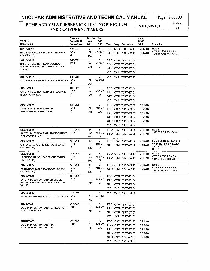
NUCLEAR ADMINISTRATIVE AND TECHNICAL MANUAL Page 43 of 100
PUMP AND VALVE INSERVICE TESTING PROGRAM 73DP-9XI01 RevisionAND COMPONENT TABLESI921
Drawing Size (in) Cat. CSJ/Valve ID Coord/Sht# Type A/P ROJIDescription Code Class Act. S.P. Test Freq Procedure VRR Remarks
SIAUV0617 SIP-002 2 B FSO QTR 73ST-9XI13 VRR-01 Note 5QTR FS FOR PRA/RA
HPSI DISCHARGE HEADER OUTBOARD G15 GL ACTIVE STO 18M 73ST-9XI13 VRR-01 18M ST FOR TS 3.3.5.4CIV (PEN. 13) 2 MO 0
SIBUVO618 SIP-002 1 B FSC QTR 73ST-9XI04
SAFETY INJECTION TANK 2A CHECK B16 GL ACTIVE FTC QTR 73ST-9X10⁴VALVE LEAKAGE TEST LINE ISOLATION 1 AO C SCQR75-X0
VALVE STC QTR 73ST-9XI04VP 2YR 73ST-9X10⁴
SIAHV0619 SIP-002 1 B VP 2YR 73ST-9X125
SIT NITROGEN SUPPLY ISOLATION VALVE D15 GL PASSIVE2 AO C
SIBUV0621 SIP-002 2 B FSC QTR 73ST-9XI04
SAFETY INJECTION TANK 2B FILL/DRAIN B12 GL ACTIVE FTC QTR 73ST-9XI04ISOLATION VALVE 2 AO C STC QTR 73ST-9XI04
VP 2YR 73ST-9XI04
SIBHV0623 SIP-002 1 B FSC CSD 73ST-9XI37 CSJ-10
SAFETY INJECTION TANK 2B E12 GL ACTIVE FSO CSD 73ST-9XI37 CSJ-10ATMOSPHERIC VENT VALVE 2 so O/C FTC CSD 73ST-9XI37 CSJ-10
STC CSD 73ST-9XI37 CSJ-10
STO CSD 73ST-9XI37 CSJ-10
VP 2YR 73ST-9XI37
SIBUVO624 SIP-002 14 B FSO 1CY 73ST-9XI25 VRR-01 Note5
SAFETY INJECTION TANK 28 DISCHARGE A12 GA ACTIVE STO 18M 73ST-9XI25 VRR-01 18M ST FOR TS 3.3.5.4
ISOLATION VALVE 1 MO 0
SIBUVO625 SIP-002 12 B FSO lCY 73ST-xXI12 VRR-01 FSO includes position stop
LPSI DISCHARGE HEADER OUTBOARD Gl1 GL ACTIVE STO 18M 73ST-xXI 12 VRR-01 verification per SR 3.5.3.7
CIV (PEN. 18) 2 MO O 18M ST forTS 3.3.5.4Note 5
SIBUVO626 SIP-002 2 B FSO QTR 73ST-9XI14 VRR-01 Note 5QTR FS FOR PRA/RAHPSI DISCHARGE HEADER OUTBOARD Gl1 GL ACTIVE STO 18M 73ST-9XI14 VRR-01 18M ST FOR TS 3.3.5.4CIV (PEN. 14) 2 MO 0
SIAUVO627 SIP-002 2 B FSO QTR 73ST-9XI13 VRR-01 Note 5OTR FS FOR PRANRAHPSI DISCHARGE HEADER OUTBOARD G12 GL ACTIVE STO 18M 73ST-9XI13 VRR-01 18M ST FORTS 3.3.5.4
CIV (PEN. 14) 2 MO 0
SIBUVO628 SIP-002 1 B FSC QTR 73ST-9X10⁴
SAFETY INJECTION TANK 2B CHECK B13 GL ACTIVE FTC QTR 73ST-9X10⁴VALVE LEAKAGE TEST LINE ISOLATION 1 AO CVALVE STC QTR 73ST-9X10⁴
VP 2YR 73ST-9XI04
SIAHV0629 SIP-002 1 B VP 2YR 73ST-9XI25
SIT NITROGEN SUPPLY ISOLATION VALVE D12 GL PASSIVE2 AO C
SIBUVO631 SIP-002 2 B FSC QTR 73ST-9XI03
SAFETY INJECTION TANK 1A FILL/DRAIN C08 GL ACTIVE FTC QTR 73ST-9XI03ISOLATION VALVE 2 AO C STC QTR 73ST-9XI03
VP 2YR 73ST-9XI03
SIBHV0633 SIP-002 1 B FSC CSD 73ST-9XI37 CSJ-10
SAFETY INJECTION TANK 1A E07 GL ACTIVE FSO CSD 73ST-9XI37 CSJ-10ATMOSPHERIC VENT VALVE 2 so O/C FTC CSD 73ST-9XI37 CSJ-10
STC CSD 73ST-9XI37 CSJ-10
STO CSD 73ST-9XI37 CSJ-10
VP 2YR 73ST-9XI37

NUCLEAR ADMINISTRATIVE AND TECHNICAL MANUAL Page 44 of 100
PUMP AND VALVE INSERVICE TESTING PROGRAM 73DP-9XI01 revision
AND COMPONENT TABLES 21
Drawing Size (in) Cat. CSJIValve ID Coord/Sht# Type A/P ROJ/Description Code Class Act. S.P. Test Freq Procedure VRR Remarks
SIAUVO634 SIP-002 14 B FSO 1CY 73ST-9XI25 VRR-01 Note 5
SAFETY INJECTION TANK 1A DISCHARGE B07 GA ACTIVE STO 18M 73ST-9XI25 VRR-01 18M ST FOR TS 3.3.5.4
ISOLATION VALVE 1 MO 0
SIAUVO635 SIP-002 12 B FSO 1CY 73ST-xXI 11 VRR-01 FSO includes position stop
LPSI DISCHARGE HEADER OUTBOARD G06 GL ACTIVE STO 18M 73ST-xXI 11 VRR-01 verification per SR 3.5.3.7CIV (PEN. 19) 2 MO O 10M ST forTS 3.3.5.4Note 5
SIBUVO636 SIP-002 2 B FSO QTR 73ST-9XI14 VRR-01 Note 5QTR FS FOR PRA/RAHPSI DISCHARGE HEADER OUTBOARD G07 GL ACTIVE STO 18M 73ST-9XI14 VRR-01 18M ST FOR TS 3.3.5.4
CIV (PEN. 15) 2 MO 0
SIAUVO637 SIP-002 2 B FSO QTR 73ST-9XI13 VRR-01 Note 5QTR FS FOR PRA/RAHPSI DISCHARGE HEADER OUTBOARD G08 GL ACTIVE STO 18M 73ST-9XI13 VRR-01 18M ST FORTS 3.3.5.4
CIV (PEN. 15) 2 MO 0
SIBUVO638 SIP-002 1 B FSC QTR 73ST-9XI03SAFETY INJECTION TANK 1A CHECK B08 GL ACTIVE FTC QTR 73ST-9X10³VALVE LEAKAGE TEST LINE ISOLATION 1 AO CVALVE STC QTR 73ST-9XI03
VP 2YR 73ST-9X10³
SIAHV0639 SIP-002 1 B VP 2YR 73ST-9XI25
SIT NITROGEN SUPPLY ISOLATION VALVE D07 GL PASSIVE2 AO C
SIBUVO641 SIP-002 2 B FSC QTR 73ST-9X10³
SAFETY INJECTION TANK 1B FILL/DRAIN B06 GL ACTIVE FTC QTR 73ST-9XI03ISOLATION VALVE 2 AO C STC QTR 73ST-9XI03
VP 2YR 73ST-9X10³
SIBHV0643 SIP-002 1 B FSC CSD 73ST-9X137 CSJ-10
SAFETY INJECTION TANK 1B E04 GL ACTIVE FSO CSD 73ST-9X137 CSJ-10ATMOSPHERIC VENT VALVE 2 so O/C FTC CSD 73ST-9XI37 CSJ-10
STC CSD 73ST-9XI37 CSJ-10
STO CSD 73ST-9XI37 CSJ-10
VP 2YR 73ST-9XI37
SIAUV0644 SIP-002 14 B FSO iCY 73ST-9XI25 VRR-01 Note5
SAFETY INJECTION TANK 1B DISCHARGE B04 GA ACTIVE STO 18M 73ST-9XI25 VRR-01 18M ST REQ'D FOR TS 3.3.5.4
ISOLATION VALVE 1 MO 0
SIAUVO645 SIP-002 12 B FSO 1CY 73ST-xXI11 VRR-01 FSO includes position stop
LPSI DISCHARGE HEADER OUTBOARD G04 GL ACTIVE STO 18M 73ST-xXIll VRR-01 verification per SR 3.5.3.7
CIV (PEN. 20) 2 MO O 18M ST for TS 3.3.5.4Note 5
SIBUVO646 SIP-002 2 B FSO QTR 73ST-9XI14 VRR-01 Note 5OTR FS FOR PRA/RAHPSI DISCHARGE HEADER OUTBOARD G04 GL ACTIVE STO 18M 73ST-9XI14 VRR-01 18M ST FORTS 3.3.5.4CIV (PEN. 16) 2 MO 0
SIAUVO647 SIP-002 2 B FSO QTR 73ST-9XI13 VRR-01 Note 5
HPSI DISCHARGE HEADER OUTBOARD G05 GL ACTIVE STO 18M 73ST-9XI13 VRR-01 QTR FS FOR PRA/RA
CIV (PEN. 16) 2 MO O 18M ST FORTS 3.3.5.4
SIBUVO648 SIP-002 1 B FSC QTR 73ST-9X10³
SAFETY INJECTION TANK 1B CHECK B06 GL ACTIVE FTC QTR 73ST-9X10³VALVE LEAKAGE TEST LINE ISOLATION 1 AO CVALVE STC QTR 73ST-9XI03
VP 2YR 73ST-9X10³
SIAHV0649 SIP-002 1 B VP 2YR 73ST-9XI25
SIT NITROGEN SUPPLY ISOLATION VALVE D05 GL PASSIVE2 AO C
SIAUVO651 SIP-002 16 A FSC iCY 73ST-9X121 VRR-01 Leak test frequency is 18 months
SHUTDOWN COOLING SUCTION C03 GA ACTIVE FSO iCY 73ST-9X121 VRR-01 perTS SR 3.4.15.1
ISOLATION VALVE 1 MO O/C LT 18M 73ST-9SI03 Note 5

NUCLEAR ADMINISTRATIVE AND TECHNICAL MANUAL Page 45 of 100
PUMP AND VALVE INSERVICE TESTING PROGRAM 73DP-9XI01 21Revisi
AND COMPONENT TABLES 21
Drawing Size (in) Cat. CSJIValve ID Coord/Sht# Type A/P ROJ/Description Code Class Act. S.P. Test Freq Procedure VRR Remarks
SIBUVO652 SIP-002 16 A FSC iCY 73ST-9XI21 VRR-01 Leak test frequency is 18 monthsper TS SR 3.4.15.1SHUTDOWN COOLING SUCTION C10 GA ACTIVE FSO iCY 73ST-9XI21 VRR-01 Note 5ISOLATION VALVE 1 MO O/C LT 18M 73ST-9SI53
SICUVO653 SIP-002 16 A FSC CSD 73ST-9XI21 CSJ-05 Leak test frequency is 18 months
SHUTDOWN COOLING SUCTION D03 GA ACTIVE FSO CSD 73ST-9XI21 CSJ-05 perTS SR 3.4.15.1
INBOARD CIV (PEN. 27) 1 MO 0/C Note 5LT 18M 73ST-9SI03 PRA/RA REQ'D QTR
EXERCISING IS N/A PER CSJ-11.
SIDUVO654 SIP-002 16 A FSC CSD 73ST-9XI21 CSJ-05 Leak test frequency is 18 monthsC~_5per TS SIR 3.4.15.1
SHUTDOWN COOLING SUCTION D10 GA ACTIVE FSO CSD 73ST-9XI21 CSJ-05 5e SINBOARD CIV (PEN. 26) MO O/C LT 18M 73ST-9SI53 PRARA REQ'D QTR
EXERCISING IS N/A PER CSJ-11.
SIAUVO655 SIP-002 16 B FSC iCY 73ST-9XI21 VRR-01 Note 5
SHUTDOWN COOLING SUCTION G03 GA ACTIVE FSO iCY 73ST-9XI21 VRR-01OUTBOARD CIV (PEN. 27) 2 MO O/C
SIBUVO656 SIP-002 16 B FSC ICY 73ST-9XI21 VRR-01 Note5
SHUTDOWN COOLING SUCTION G10 GA ACTIVE FSO iCY 73ST-9XI21 VRR-01OUTBOARD CIV (PEN. 26) 2 MO O/C
SIAHV0657 SIP-001 16 B FSC iCY 73ST-9XI13 VRR-01 Note 5SHUTDOWN COOLING HEAT H03 BF ACTIVE FSO iCY 73ST-9XI13 VRR-01EXCHANGER OUTLET THROTTLE VALVE 2 MO O/C
SIBHV0658 SIP-001 16 B FSC iCY 73ST-9XI14 VRR-01 Note 5
SHUTDOWN COOLING HEAT C03 BF ACTIVE FSO iCY 73ST-9XI14 VRR-01EXCHANGER OUTLET THROTTLE VALVE 2 MO O/C
SIBUVO659 SIP-O01 4 B FSC QTR 73ST-9XI14SI COMBINED RECIRC TO RWT B06 GL ACTIVE FSO QTR 73ST-9XI14ISOLATION VALVE 2 so O/C FTC QTR 73ST-9XI14
STC QTR 73ST-9XI14
STO QTR 73ST-9XI14
VP 2YR 73ST-9XI14
SIAUVO660 SIP-O01 4 B FSC QTR 73ST-9XI13SI COMBINED RECIRC TO RWT F06 GL ACTIVE FSO QTR 73ST-9XI13ISOLATION VALVE 2 so O/C FTC QTR 73ST-9XI13
STC QTR 73ST-9XI13
STO QTR 73ST-9XI13
VP 2YR 73ST-9XI13
SIAUVO664 SIP-001 2 B FSC ICY 73ST-9XI03 VRR-01 Note 5CP To GI GIL ACTIVE FSO iCY 73T-9X03 VRR-01 18M ST REQ'D FOR TS 3.3.5.4
CONTAINMENT SPRAY PUMP RECIRC C 73ST-9SI06 may be required forRWT ISOLATION VALVE 2 MO 0/C STC 18M 73ST-9XI03 VRR-01 retest after open limit switch
STO 18M 73ST-9XI03 VRR-01 adjustment
SIBUV0665 SIP-001 2 B FSC ICY 73ST-9XI04 VRR-01 Note.518M ST REQ'D FOR TS 3.3.5.4
CONTAINMENT SPRAY PUMP RECIRC TO B10 GL ACTIVE FSO 1CY 73ST-9XI04 VRR-01 73ST-9SI06 may be required forRWT ISOLATION VALVE 2 MO O/C STC 18M 73ST-9X10⁴ VRR-01 retest after open limit switch
STO 18M 73ST-9X10⁴ VRR-01 adjustment
SIAUVO666 SIP-001 2 B FSC iCY 73ST-9XI13 VRR-01 Note 5HPSI PUMP RECIRC TO RWT ISOLATION F10 GL ACTIVE FSO ICY 73ST-9XI13 VRR-01 18M ST REQ'D FOR TS 3.3.5.4
VALVE 2 MO O/C STC 18M 73ST-9XI13 VRR-01
STO 18M 73ST-9XI13 VRR-01

NUCLEAR ADMINISTRATIVE AND TECHNICAL MANUAL Page 46 of 100
PUMP AND VALVE INSERVICE TESTING PROGRAM 73DP-9XI01 Revision
AND COMPONENT TABLES 21
Drawing Size (in) Cat. CSJIValve ID Coord/Sht# Type A/P ROJ/Description Code Class Act. S.P. Test Freq Procedure VRR Remarks
SIBUVO667 SIP-001 2 B FSC iCY 73ST-9XI14 VRR-01 Note 5
HPSI PUMP RECIRC TO RWT A10 GL ACTIVE FSO iCY 73ST-9XI14 VRR-01 18M ST REQ'D FORTS 3.3.5.42 MO O/C STC 18M 73ST-9XI14 VRR-01
STO 18M 73ST-9XI14 VRR-01
SIBUVO668 SIP-001 2 B FSC iCY 73ST-9X14 VRR-01 Note 5
LPSI PUMP RECIRC TO RWT ISOLATION B10 GL ACTIVE FSO iCY 73ST-9X14 VRR-01 18M ST REQ'D FOR TS 3.3.5.4
VALVE 2 MO O/C STC 18M 73ST-9XI14 VRR-01
STO 18M 73ST-9XI14 VRR-01
SIAUVO669 SIP-001 2 B FSC ICY 73ST-9XI13 VRR-01 Note 5
LPSI PUMP RECIRC TO RWT ISOLATION G10 GL ACTIVE FSO ICY 73ST-9XI13 VRR-01 18M ST REQ'D FOR TS 3.3.5.4
VALVE 2 MO 0/C STC 18M 73ST-9XI13 VRR-01
STO 18M 73ST-9XI13 VRR-01
SIBUVO671 SIP-O01 8 B FSC iCY 73ST-9XI04 VRR-01 Note 5
CONTAINMENT SPRAY CONTROL VALVE C06 GA ACTIVE FSO iCY 73ST-9XI04 VRR-01 18M ST REQ'D FOR TS 3.3.5.4
AND OUTBOARD CIV (PEN. 22) 2 MO O/C SrC 18M 73ST-9X10⁴ VRR-01
STO 18M 73ST-9XI04 VRR-01
SIAUVO672 SIP-001 8 B FSC iCY 73ST-9XI03 VRR-01 Note5
CONTAINMENT SPRAY CONTROL VALVE G06 GA ACTIVE FSO iCY 73ST-9XI03 VRR-01 18M ST REQ'D FOR TS 3.3.5.4
AND OUTBOARD CIV (PEN. 21) 2 MO O/C STC 18M 73ST-9X10³ VRR-01
STO 18M 73ST-9XI03 VRR-01
SIAUVO673 SIP-001 24 A FSC 18M 73ST-9Xi03 VRR-01 Note5
CONTAINMENT SUMP TO SI PUMP G16 BF ACTIVE FSO 18M 73ST-9XI03 VRR-01 18M ST FORTS 3.3.5.4
SUCTION INBOARD CIV (PEN. 23) 2 MO O/C LT 2YR 73ST-9X143
STO 18M 73ST-9XI03 VRR-01
SIAUVO674 SIP-O01 24 B FSO QTR 73ST-9XI03 VRR-01 Note 5QTR FS FOR PRA/RA
CONTAINMENT SUMP TO SI PUMP G14 BF ACTIVE STO 18M 73ST-9XI03 VRR-01 18M ST FOR TS 3.3.5.4SUCTION OUTBOARD CIV 2 MO 0(PEN. 23)
SIBUVO675 SIP-001 24 A FSC 18M 73ST-9XI04 VRR-01 Note 5
CONTAINMENT SUMP TO SI PUMP A16 BF ACTIVE FSO 18M 73ST-9X10⁴ VRR-01 18M ST FOR TS 3.3.5.4
SUCTION INBOARD CIV (PEN. 24) 2 MO O/C LT 2YR 73ST-9X143
STO 18M 73ST-9X10⁴ VRR-01
SIBUVO676 SIP-001 24 B FSO QTR 73ST-9X10⁴ VRR-01 Note5QTR FS FOR PRA/RACONTAINMENT SUMP TO SI PUMP A14 BF ACTIVE STO 18M 73ST-9X10⁴ VRR-01 18M ST FOR TS 3.3.5.4SUCTION OUTBOARD CIV (PEN. 24) 2 MO O
SIAHV0678 SIP-01 10 B FSC ICY 73ST-9XI03 VRR-01 Note 5
S/D COOLING HEAT EXCHANGER H09 GA ACTIVE FSO iCY 73ST-9XI03 VRR-01ISOLATION TRAIN A 2 MO O/C
SIBHV0679 SIP-001 10 B FSC iCY 73ST-9XI04 VRR-01 Note 5
S/D COOLING HEAT EXCHANGER C09 GA ACTIVE FSO iCY 73ST-9X10⁴ VRR-01ISOLATION TRAIN B 2 MO O/C
SIAUVO682 SIP-001 2 A AJ CLR 73ST-9CL01SAFETY INJECTION TANK FILL LINE CIV D10 GL ACTIVE FSC QTR 73ST-9XI03(PEN. 28) 2 AO C FTC QTR 73ST-9X10³
STC QTR 73ST-9X10³
VP 2YR 73ST-9X10³
SIAHV0683 SIP-001 20 B FSC QTR 73ST-9X10³ VRR-01 Note 5
LPSI PUMP SUCTION ISOLATION TRAIN A F13 GA ACTIVE FSO QTR 73ST-9XI03 VRR-01 QTR FS FOR PRA/RA2 MO O/C

NUCLEAR ADMINISTRATIVE AND TECHNICAL MANUAL Page 47 of 100
PUMP AND VALVE INSERVICE TESTING PROGRAM 73DP-9XI01 I Revision
AND COMPONENT TABLES 21
Drawing Size (in) Cat. CSJ/Valve ID Coord/Sht# Type A/P ROJIDescription Code Class Act. S.P. Test Freq Procedure VRR Remarks
SIAHV0684 SIP-001 10 B FSC iCY 73ST-9XI03 VRR-01 Note 5
CTMT SPRAY TO S/D COOLING HEAT H09 GA ACTIVE FSO iCY 73ST-9XI03 VRR-01EXCHANGER ISOLATION TRAIN A 2 MO O/C
SIAHV0685 SIP-001 10 B FSC iCY 73ST-9XI13 VRR-01 Note5
LPSI PUMP TO SHUTDOWN COOLING G08 GA ACTIVE FSO iCY 73ST-9XI13 VRR-01HEAT EXCHANGER ISOLATION VALVE 2 MO O/C
SIAHV0686 SIP-001 20 B FSC iCY 73ST-9XI13 VRR-01 Note 5
SHUTDOWN COOLING HEAT H06 GA ACTIVE FSO ICY 73ST-9XI13 VRR-01EXCHANGER OUTLET TO LPSI ISOLATION 2 MO O/CVALVE
SIAHV0687 SIP-001 10 B FSC iCY 73ST-9XI13 Note 5
CTMT SPRAY ISOLATION TRAIN A G06 GA ACTIVE FSO ICY 73ST-9XI132 MO 0
SIAHV0688 SIP-OOl 10 B FSC iCY 73ST-9X10³ VRR-01 Note 5
CONTAINMENT SPRAY BYPASS VALVE G09 GA ACTIVE FSO iCY 73ST-9XI03 VRR-012 MO C
SIBHV0689 SIP-001 10 B FSC iCY 73ST-9X10⁴ VRR-01 Note 5
CTMT SPRAY TO S/D COOLING HEAT C09 GA ACTIVE FSO iCY 73ST-9X10⁴ VRR-01EXCHANGER ISOLATION TRAIN B 2 MO O/C
SIBHV0690 SIP-002 10 B FSC iCY 73ST-9XI04 VRR-01 Note 5
SHUTDOWN COOLING WARMUP BYPASS H13 GL ACTIVE FSO iCY 73ST-9XI04 VRR-01CONTAINMENT ISOLATION VALVE (PEN. 2 MO O/C26)
SIAHV0691 SIP-002 10 B FSC iCY 73ST-9XI03 VRR-01 Note 5
SHUTDOWN COOLING WARMUP BYPASS H03 GL ACTIVE FSO iCY 73ST-9XI03 VRR-01CONTAINMENT ISOLATION VALVE (PEN. 2 MO O/C27)
SIBHV0692 SIP-001 20 B FSC QTR 73ST-9XI04 VRR-01 Note 5
LPSI PUMP SUCTION ISOLATION TRAIN B B13 GA ACTIVE FSO QTR 73ST-9XI04 VRR-01 QTR FS FOR PRNRA2 MO O/C
SIBHV0693 SIP-001 10 B FSC iCY 73ST-9XI04 VRR-01 Note 5
CONTAINMENT SPRAY BYPASS VALVE C09 GA ACTIVE FSO ICY 73ST-9XI04 VRR-012 MO O/C
SIBHV0694 SIP-001 10 B FSC iCY 73ST-9XI14 VRR-01 Note 5
LPSI CROSS CONNECT VALVE TO C08 GA ACTIVE FSO ICY 73ST-9XI14 VRR-01SHUTDOWN COOLING HEAT EXCHANGER 2 MO O/C
SIBHV0695 SIP-001 10 B FSC iCY 73ST-9XI14 Note 5
CTMT SPRAY ISOLATION TRAIN B C06 GA ACTIVE FSO iCY 73ST-9XI142 MO 0
SIBHV0696 SIP-001 20 B FSC iCY 73ST-9XI14 VRR-01 Note 5
SHUTDOWN COOLING HEAT C06 GA ACTIVE FSO iCY 73ST-9XI14 VRR-01EXCHANGER OUTLET TO LPSI ISOLATION 2 MO O/CVALVE
SIAHV0698 SIP-001 4 B FSC iCY 73ST-9XI33 VRR-01 Note 5PREVIOUSLY TESTED IN 73ST-
HPSI HEADER DISCHARGE ISOLATION F04 GA ACTIVE FSO 1CY 73ST-gXI33 VRR-01 9XI13.VALVE 2 MO O/C
SIBHV0699 SIP-001 4 B FSC iCY 73ST-9XI33 VRR-01 Note 5PREVIOUSLY TESTED IN 73ST-
HPSI HEADER DISCHARGE ISOLATION B03 GA ACTIVE FSO lCY 73ST-9XI33 VRR-01 9XI14.VALVE 2 MO O/C
SIAUVO708 SIP-001 0.5 B STC RFO 73ST-9XI21 STC is an augmented test,CONTAINMENT SUMP TRAIN A SAMPLE G15 GL PASSIVE VP 2YR 73ST-9X21 performed at RFO to satisfy ESFTO PASS ISOLATION VALVE (PEN. 23) 2 P0 C response time testing per SR3.3.5.4 and CIV isolation time
testing per SR 3.6.3.5.
SIAUVO709 SIP-001 0.5 B STC RFO 73ST-9XI21 STC is an augmented test,MINI-FLOW RECIRC LINE SAMPLE E08 GL PASSIVE VP 2YR 73ST-9XI21 performed at RFO to satisfy ESFISOLATION VALVE 2 50 C response time testing per SR3.3.5.4.
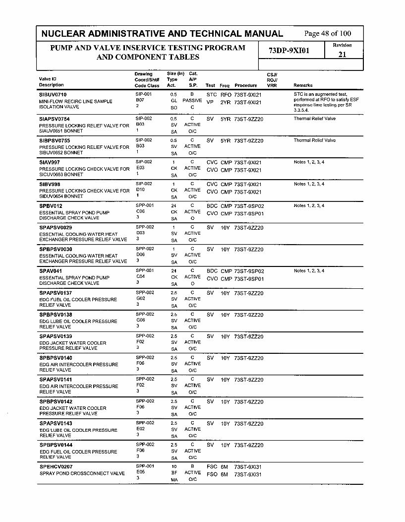
NUCLEAR ADMINISTRATIVE AND TECHNICAL MANUAL Page 48 of 100
PUMP AND VALVE INSERVICE TESTING PROGRAM 73DP-XI01 Revision
AND COMPONENT TABLES 21
Drawing Size (in) Cat. CSJIValve ID Coord/Sht# Type A/P ROJIDescription Code Class Act. S.P. Test Freq Procedure VRR Remarks
SIBUVO710 SIP-0O1 0.5 B STC RFO 73ST-9XI21 STC is an augmented test,MINI-FLOW RECIRC LINE SAMPLE 807 GL PASSIVE VP 2YR 73ST-9XI21 performed at RFO to satisfy ESFISOLATION VALVE 2 SO C response time testing per SR3.3.5.4.
SlAPSV0754 SIP-002 0.5 C SV 5YR 73ST-9ZZ20 Thermal Relief Valve
PRESSURE LOCKING RELIEF VALVE FOR B03 SV ACTIVESIAUVO651 BONNET 1 SA O/C
SIBPSVO755 SIP-002 0.5 C SV 5YR 73ST-9ZZ20 Thermal Relief ValvePRESSURE LOCKING RELIEF VALVE FOR B03 SV ACTIVESIBUV0652 BONNET 1 SA O/C
SIAV997 SIP-002 1 C CVC CMP 73ST-9XI21 Notes 1,2, 3, 4
PRESSURE LOCKING CHECK VALVE FOR E03 CK ACTIVE CVO CMP 73ST-9XI21SICUV0653 BONNET I SA O/C
SIBV998 SIP-002 1 C CVC CMP 73ST-9XI21 Notes 1,2, 3, 4
PRESSURE LOCKING CHECK VALVE FOR D10 CK ACTIVE CVO CMP 73ST-9XI21SIDUV0654 BONNET 1 SA O/C
SPBV012 SPP-00l 24 C BDC CMP 73ST-9SP02 Notes 1,2, 3, 4
ESSENTIAL SPRAY POND PUMP C06 CK ACTIVE CVO CMP 73ST-9SP01DISCHARGE CHECK VALVE 3 SA 0
SPAPSVO029 SPP-002 1 C SV 10Y 73ST-9ZZ20
ESSENTIAL COOLING WATER HEAT D03 SV ACTIVEEXCHANGER PRESSURE RELIEF VALVE 3 SA O/C
SPBPSVO030 SPP-002 1 C SV 10Y 73ST-9ZZ20
ESSENTIAL COOLING WATER HEAT D06 SV ACTIVEEXCHANGER PRESSURE RELIEF VALVE 3 SA O/C
SPAV041 SPP-001 24 C BDC CMP 73ST-9SP02 Notes 1,2, 3, 4
ESSENTIAL SPRAY POND PUMP C04 CK ACTIVE CVO CMP 73ST-9SP01DISCHARGE CHECK VALVE 3 SA 0
SPAPSVO137 SPP-002 2.5 C SV 10Y 73ST-9ZZ20
EDG FUEL OIL COOLER PRESSURE G02 SV ACTIVERELIEF VALVE 3 SA O/C
SPBPSV0138 SPP-002 2.5 C SV 10Y 73ST-9ZZ20EDG LUBE OIL COOLER PRESSURE G06 SV ACTIVERELIEF VALVE 3 SA O/C
SPAPSVO139 SPP-002 2.5 C SV 10Y 73ST-9ZZ20EDG JACKET WATER COOLER F02 SV ACTIVEPRESSURE RELIEF VALVE 3 SA O/C
SPBPSVO140 SPP-002 2.5 C SV 10Y 73ST-9ZZ20EDG AIR INTERCOOLER PRESSURE F06 SV ACTIVERELIEF VALVE 3 SA O/C
SPAPSVO141 SPP-002 2.5 C SV 10Y 73ST-9ZZ20EDG AIR INTERCOOLER PRESSURE F02 SV ACTIVERELIEF VALVE 3 SA O/C
SPBPSV0142 SPP-002 2.5 C SV 10Y 73ST-9ZZ20EDG JACKET WATER COOLER F06 SV ACTIVEPRESSURE RELIEF VALVE 3 SA O/C
SPAPSVO143 SPP-002 2.5 C SV 10Y 73ST-9ZZ20EDG LUBE OIL COOLER PRESSURE E02 SV ACTIVERELIEF VALVE 3 SA O/C
SPBPSVO144 SPP-002 2.5 C SV 10Y 73ST-9ZZ20EDG FUEL OIL COOLER PRESSURE F06 SV ACTIVERELIEF VALVE 3 SA O/C
SPEHCV0207 SPP-001 10 B FSC 6M 73ST-9XI31SPRAY POND CROSSCONNECT VALVE E05 BF ACTIVE FSO 6M 73ST-9XI31
3 MA O/C

NUCLEAR ADMINISTRATIVE AND TECHNICAL MANUAL Page 49 of 100
PUMP AND VALVE INSERVICE TESTING PROGRAM 73DP-9XI01RevisionAND COMPONENT TABLES 21
Drawing Size (in) Cat. CSJ/Valve ID Coord/Sht# Type A/P ROJ/Description Code Class Act. S.P. Test Freq Procedure VRR Remarks
SPEHCV0208 SPP-001 10 B FSC 6M 73ST-9XI31
SPRAY POND CROSSCONNECT VALVE E04 BF ACTIVE FSO 6M 73ST-9X1313 MA O/C
SSBUV0200 SSP-001 0.375 A AJ CLR 73ST-9CL01
HOT LEG SAMPLE LINE OUTBOARD CIV G05 GL ACTIVE FSC QTR 73ST-9XI06(PEN. 42C) 2 so C FTC QTR 73ST-9XI06
STC QTR 73ST-9XI06
VP 2YR 73ST-9XI06
SSBUV0201 SSP-001 0.375 A AJ CLR 73ST-9CLO1
PRESSURIZER SURGE LINE SAMPLE LINE F05 GL ACTIVE FSC QTR 73ST-9XI06OUTBOARD CIV 2 so C(PEN. 42A) FTC QTR 73ST-9XI06
STC QTR 73ST-9X10⁶
VP 2YR 73ST-9XI06
SSBUV0202 SSP-001 0.375 A AJ CLR 73ST-9CLO1
PRESSURIZER STEAM SPACE SAMPLE F05 GL ACTIVE FSC QTR 73ST-9XI06LINE OUTBOARD CIV 2 so C(PEN. 42B) FTC QTR 73ST-9XI06
STC QTR 73ST-9X10⁶VP 2YR 73ST-9XI06
SSAUV0203 SSP-001 0.375 A AJ CLR 73ST-9CLO1HOT LEG SAMPLE LINE INBOARD CIV G07 GL ACTIVE FSC QTR 73ST-9XI06(PEN. 42C) 2 so C FTC QTR 73ST-9X10⁶
STC QTR 73ST-9X10⁶
VP 2YR 73ST-9X10⁶
SSAUV0204 SSP-001 0.375 A AJ CLR 73ST-9CL01
PRESSURIZER SURGE LINE SAMPLE LINE F07 GL ACTIVE FSC QTR 73ST-9XI06INBOARD CIV (PEN. 42A) 2 so C FTC QTR 73ST-9X10⁶
STC QTR 73ST-9XI06
VP 2YR 73ST-9XI06
SSAUV0205 SSP-001 0.375 A AJ CLR 73ST-9CLO1
PRESSURIZER STEAM SPACE SAMPLE E07 GL ACTIVE FSC QTR 73sT-9XI06LINE INBOARD CIV 2 so C(PEN. 42B) FTC QTR 73ST-9XI06
STC QTR 73ST-9XI06VP 2YR 73ST-9XI06
WCEV039 WCP-001 10 AC AJ CLR 73ST-9CLO1 Notes 1,2, 3, 4
NORMAL CHILLED WATER SUPPLY TO E05 CK ACTIVE CVC CMP 73ST-9CLO1CONTAINMENT INBOARD CIV (PEN. 60) 2 SA O/C CVO CMVP 40DP-90OP5
WCBUVO061 WCP-001 10 A AJ CLR 73ST-9CLO1 Note 5
NORMAL CHILLED WATER RETURN FROM G05 GA ACTIVE FSC lCY 73ST-9XI07 VRR-01 18M ST REQ'D FOR TS 3.3.5.4
CONTAINMENT INBOARD CIV (PEN. 61) 2 MO C STC 18M 73ST-9XI07 VRR-01
WCAUVO062 WCP-001 10 A AJ CLR 73ST-9CLO1 Note 5
NORMAL CHILLED WATER RETURN FROM G05 GA ACTIVE FSC 1CY 73ST-9XI07 VRR-01 18M ST REQ'D FORTS 3.3.5.4
CONTAINMENT OUTBOARD CIV (PEN. 61) 2 MO C STC i8M 73ST-9XI07 VRR-01
WCBUVO063 WCP-001 10 A AJ CLR 73ST-9CLO1 Note 5
NORMAL CHILLED WATER SUPPLY TO G06 GA ACTIVE FSC 1CY 73ST-9XI07 VRR-01 18M ST REQ'D FOR TS 3.3.5.4
CONTAINMENT OUTBOARD CIV (PEN. 60) 2 MO C STC 18M 73ST-9X10⁷ VRR-01
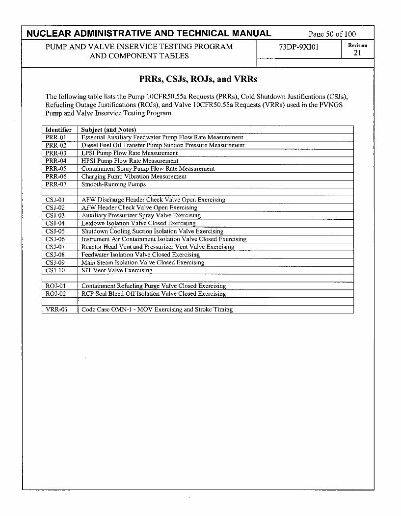
NUCLEAR ADMINISTRATIVE AND TECHNICAL MANUAL Page 50 of 100
PUMP AND VALVE INSERVICE TESTING PROGRAM 73DP-9XI01 Revision
AND COMPONENT TABLES 21
PRRs, CSJs, ROJs, and VRRs
The following table lists the Pump 10CFR50.55a Requests (PRRs), Cold Shutdown Justifications (CSJs),Refueling Outage Justifications (ROJs), and Valve 1OCFR50.55a Requests (VRRs) used in the PVNGSPump and Valve Inservice Testing Program.
Identifier Subject (and Notes)PRR-01 Essential Auxiliary Feedwater Pump Flow Rate MeasurementPRR-02 Diesel Fuel Oil Transfer Pump Suction Pressure MeasurementPRR-03 LPSI Pump Flow Rate MeasurementPRR-04 HPSI Pump Flow Rate MeasurementPRR-05 Containment Spray Pump Flow Rate MeasurementPRR-06 Charging Pump Vibration MeasurementPRR-07 Smooth-Running Pumps
CSJ-01 AFW Discharge Header Check Valve Open ExercisingCSJ-02 AFW Header Check Valve Open ExercisingCSJ-03 Auxiliary Pressurizer Spray Valve ExercisingCSJ-04 Letdown Isolation Valve Closed ExercisingCSJ-05 Shutdown Cooling Suction Isolation Valve ExercisingCSJ-06 Instrument Air Containment Isolation Valve Closed ExercisingCSJ-07 Reactor Head Vent and Pressurizer Vent Valve Exercising
CSJ-08 Feedwater Isolation Valve Closed ExercisingCSJ-09 Main Steam Isolation Valve Closed ExercisingCSJ-10 SIT Vent Valve Exercising
ROJ-01 Containment Refueling Purge Valve Closed ExercisingROJ-02 RCP Seal Bleed-Off Isolation Valve Closed Exercising
VRR-01 Code Case OMN- 1 - MOV Exercising and Stroke Timing

NUCLEAR ADMINISTRATIVE AND TECHNICAL MANUAL Page 51 of 100
PUMP AND VALVE INSERVICE TESTING PROGRAM 73DP-9XI01 Revision
AND COMPONENT TABLES 21
PUMP 10CFR50.55a REQUEST PRR-01Relief Request In Accordance with 10CFR50.55a(f)(5)(iii)
-- Inservice Testing Impracticality -
Essential Auxiliary Feedwater Pump Flow Rate Measurement During Group B Test
Component(s)Affected:
Component/SystemFunction:
Applicable CodeEdition and Addenda:
Applicable CodeRequirement(s):
Pump ID Pump Description Code PumpClass Group
AFA-P01 Essential Auxiliary Feedwater Pump 3 B(Turbine-Driven)
AFB-P0 1 Essential Auxiliary Feedwater Pump 3 BI (Motor-Driven) I
The essential auxiliary feedwater (AF) pumps supply water to the steamgenerators during an accident. They also can be used to supply feedwaterto the steam generators during plant startup and shutdown.
ASME OM Code 2001 Edition w/2003 Addenda
ISTB-3300, "Reference Values," ISTB-3300(e)(2), "Reference values shallbe established within ± 20% of pump design flow for the Group A andGroup B tests, if practicable. If not practicable, the reference point flowrate shall be established at the highest practical flow rate."
ISTB-5122, "Group B Test Procedure," "Group B tests shall be conductedwith the pump operating at a specified reference point. The test parametervalue identified in Table ISTB-3000-1 shall be determined and recorded asrequired by this paragraph."
ISTB-5122(b), "The differential pressure or flow rate shall be determinedand compared to its reference value.

NUCLEAR ADMINISTRATIVE AND TECHNICAL MANUAL Page 52 of 100
PUMP AND VALVE INSERVICE TESTING PROGRAM 73DP-9XI01 Revision
AND COMPONENT TABLES 21
Impracticality ofCompliance:
Burden Caused byCompliance:
The Code requirements to establish the Group B reference point flow rateat the highest practical flow rate and operate the pump at a specifiedreference point (i.e., fix the flow to a specified value) are impractical sincethis is a fixed resistance recirculation path with no flow instrumentationprovided. When the pump operates on minimum flow recirculation(approx. 260 gpm) the specified reference point is essentially achieved bythe recirculation lines fixed resistance. To establish the fixed resistance theminimum flow recirculation line contains an administratively controlledlocked-throttled drag valve and a locked open manual isolation valve. Theuse of an ultrasonic flowmeter was evaluated and determined impracticaldue to the difficulty in establishing an application specific 2% calibrationon the AF mini-flow piping. Allowing the flow to remain fixed by thelocked-in resistance increases the potential for repeatable test results anddegradation monitoring rather than changing the resistance based onultrasonic flow meter readout flucuations. With this understanding, there islittle value added in installing flow instrumentation to measure and recordthe flow with instrumentation that meets IST-3510 requirements. The fixedresistance methodology is repeatable from test to test and accomplishes thesame result as if flow were being measured and recorded.
To comply with the Code there are only two practical flow paths availablefor testing AFA-PO1 and AFB-PO1. The primary flow path is into the mainfeedwater lines to the steam generators. The other flow path is theminimum flow recirculation line that recirculates back to the condensatestorage tank. The flow path to the steam generators is equipped with flowinstrumentation, but the recirculation line is a fixed-resistance circuit withno provisions for flow indication.
Use of the primary flow path at power would inject cold auxiliaryfeedwater into the main feedwater lines. The resulting temperatureperturbations could lead to thermal shock / fatigue damage to the feedwaterpiping and steam generators, and the cooldown of the reactor coolantsystem could cause undesirable reactivity variations and powerfluctuations.
Modifying the minimum flow recirculation line to provide flow indicationto meet the ± 2% accuracy requirement as specified in Table ISTB-3500-1adds little value since the flow is fixed at approximately 260 gpm anddifferential pressure is used to monitor degradation. Use of an ultrasonicflow meter and possible adjustment of the fixed resistance introduces thepotential for less accurate degradation monitoring than currently employed.

NUCLEAR ADMINISTRATIVE AND TECHNICAL MANUAL Page 53 of 100
PUMP AND VALVE INSERVICE TESTING PROGRAM 73DP-9XI01 Revision
AND COMPONENT TABLES 21
Proposed Alternativeand Basis for Use: During plant operation, quarterly Group B pump testing for pumps AFA-
P01 and AFB-PO1 shall be conducted at mini-flow conditions using theminimum flow recirculation line fixed resistance to establish the specifiedreference point. ISTB-5 1 00(b)(2) allows the use of bypass test loops to beused for Group B tests. The PVNGS minimum flow recirculation line isdesigned to meet the pump manufacturers operating specifications with aflow rate of approximately 260 gpm. Flow rate will not be measured orrecorded. To monitor for degradation, pump differential pressure shall bedetermined and compared to its reference value and the associated range asspecified in Table ISTB-5100-1.
Pumps AFA-P01 and AFB-P01 will be comprehensively tested inaccordance with ISTB-5123, "Comprehensive Test Procedure," on abiennial (2-year) frequency as specified in Table ISTB-3400-1.
Pumps AFA-P01 and AFB-PO1 are standby pumps. Little degradation isexpected during plant plant operation when the pumps are idle except fortesting. Testing the pumps within ± 20% of design flow on a 2-yearfrequency provides additional information regarding the condition of thepumps.
Conclusion: 10 CFR50.55a(f)((5)(iii) states:
"If the licensee has determined that conformance with certain coderequirements is impractical for its facility, the licensee shall notify theCommission and submit, as specified in § 50.4 information to support thedetermination."
The information provided in this request supports the determination that it isimpractical to meet the Code requirements to establish the Group Breference point flow rate at the highest practical flow rate and operate thepump at a specified reference point (i.e., fix the flow to a specified value)since this is a fixed resistance recirculation path with no flowinstrumentation provided.
The proposed alternative identified in this 1OCFR50.55a Request shall beutilized during the Third 10-Year IST Interval.
Complies with NRC Generic Letter 89-04, Position 9. Relief Request PRR-01 was previously authorized for Palo Verde pursuant to10 CFR 50.55a(f)(6)(i) for Interval 2 in the NRC Safety Evaluation datedJuly 8, 1999. (TAC NOS. MA0757, MA0758 and MA0759) (ADAMSAccession No. 9907150128).
Duration of ProposedAlternative:
Precedents:

NUCLEAR ADMINISTRATIVE AND TECHNICAL MANUAL Page 54 of 100
PUMP AND VALVE INSERVICE TESTING PROGRAM 73DP-9XI01 Revision
AND COMPONENT TABLES 21
PUMP 10CFR50.55a REQUEST PRR-02Relief Request In Accordance with 10CFR50.55a(a)(3)(i)
-- On the basis that the proposed alternative provides an acceptable level of quality and safety --
Diesel Fuel Oil Transfer Pump Suction Pressure Measurement
Component(s)Affected:
Component/SystemFunction:
Applicable CodeEdition andAddenda:
Applicable CodeRequirement(s):
Pump ID Pump Description Code PumpClass Group
DFA-P01 Diesel Generator Fuel Oil 3 BTransfer Pump
DFB-P0l Diesel Generator Fuel Oil 3 BTransfer Pump
Transfer diesel fuel from the fuel oil storage tank to the EDG day tank.
ASME OM Code 2001 Edition w/2003 Addenda
ISTB-35 10, "General," ISTB-35 10(a), "Accuracy", Instrument accuracyshall be within the limits of Table ISTB-3500-1.
Table ISTB-3500-1, "Required Instrument Accuracy", Pressure,Comprehensive Test, + 0.5% accuracy.
There are no inlet pressure gauges installed for this pump configuration.Specifically, the pumps are horizontal, centrifugal type with an integralmotor. They operate submerged in the diesel fuel oil storage tank. The pumpand drive motor are completely housed in an enclosed steel casing with noshaft penetrations requiring seals or packing. The casing has a hermeticallysealed compartment for the stator windings of the motor to prevent entranceof pumped liquid or vapor. Pump bearings are cooled by recirculation ofpumped fluid. The entire assembly is suspended from a cover plate, which isbolted to a nozzle on the tank.
The diesel generator fuel oil storage tank is equipped with levelinstrumentation (DFN-LI-33 and DFN-LI-34) having a calculated loopaccuracy of± 1.5%. The instrument reads out in percent of tank level whichis converted to suction pressure during the quarterly pump surveillance test.The calibrated instrument range results in a suction pressure span of 0.2 psigto 4.4 psig. This instrument accuracy is acceptable for use during Group Bpump testing but does not meet the ± 0.5% accuracy as required by TableISTB-3500-1 for Comprehensive Pump Testing performed every 2 years.
Reason forRequest:

NUCLEAR ADMINISTRATIVE AND TECHNICAL MANUAL Page 55 of 100
PUMP AND VALVE INSERVICE TESTING PROGRAM 73DP-9XI01 Revision
AND COMPONENT TABLES 21
Proposed The installed instrumentation converts to a full-scale range of 4.4 psig,Alternatives and which only slightly exceeds the pump suction reference value of 3.8 psigBasis for Use: (full scale equals 1.15 times reference).
Considering the existing 1.5% accuracy of the level instrument, the readingcould be as high as 3.85 psig or as low as 3.74 psig. This results in less thana 0.06 psig difference in the readings and is considered insignificant whenmonitoring for degradation. The existing accuracy is equivalent to the 1.5%minimum accuracy allowed by the combination of instrument full-scalerange and accuracy as specified in Subsection ISTB 3510 for comprehensivepump testing. This accuracy provides adequate assurance of operability. Thecurrent instrumentation provides sufficient repeatability to allow for anevaluation of the pump hydraulic condition and detect pump degradation.
Use of the existing diesel generator fuel oil storage tank instrumentationshould be considered an acceptable alternative to the accuracy requirementsof Table ISTB-3500-1.
Supporting Facts:
Technical Specification 3.8.3.1 requires that the diesel generator fuel oilstorage tank be maintained at > 80% which is verified every 31 days toassure sufficient supply for 7 days of full load operation. The differencebetween minimum allowable tank level and top of the tank is only 26.4inches. Due to strict controls placed on fuel oil level, the suction pressurecannot vary by more than 0.7 psig. Review of test history shows that themaximum variance recorded is approximately 0.5 psig. The suction pressureis essentially fixed by the TS level requirements, allowing for very littlevariation in suction pressure. There is no value added in providing moreprecise suction pressure instrumentation for monitoring pump degradation.
The following test history shows the essentially constant suction pressure:
Unit Pump ID Date SuctionPressure
1 1MDFAP01 1 6/6/2006 1 3.81MDFAP01 8/24/2006 41MDFAP01 11/15/2006 41MDFAP01 2/8/2007 41MDFAP01 5/3/2007 3.91MDFBP01 5/18/2006 4.31MDFBP01 8/10/2006 3.91MDFBP01 11/2/2006 3.61MDFBP01 1/25/2007 3.8
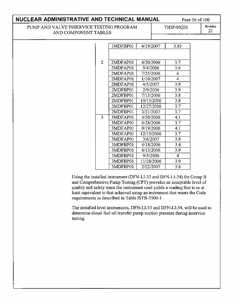
NUCLEAR ADMINISTRATIVE AND TECHNICAL MANUAL Page 56 of 100
PUMP AND VALVE INSERVICE TESTING PROGRAM 73DP-9XI01 Revision
AND COMPONENT TABLES 21
2
1MDFBP01 4/19/2007 3.85
2MDFAP01 4/20/2006 3.72MDFAP01 5/4/2006 3.62MDFAP01 7/25/2006 42MDFAP01 1/10/2007 42MDFAP01 4/5/2007 3.92MDFBP01 2/9/2006 3.92MDFBP01 7/13/2006 3.82MDFBP01 10/15/2006 3.82MDFBP01 12/27/2006 3.72MDFBP01 3/21/2007 3.7
3 3MDFAP01 4/30/2006 4.13MDFAP01 6/28/2006 3.73MDFAP01 9/19/2006 4.13MDFAP01 12/15/2006 3.73MDFAP01 3/6/2007 3.93MDFBP01 4/18/2006 3.43MDFBP01 6/13/2006 3.93MDFBP01 9/5/2006 43MDFBP01 11/28/2006 3.93MDFBP01 2/22/2007 3.8
Using the installed instrument (DFN-LI-33 and DFN-LI-34) for Group Band Comprehensive Pump Testing (CPT) provides an acceptable level ofquality and safety since the instrument used yields a reading that is as atleast equivalent to that achieved using an instrument that meets the Coderequirements as described in Table ISTB-3500-1
The installed level instruments, DFN-LI-33 and DFN-LI-34, will be used todetermine diesel fuel oil transfer pump suction pressure during inservicetesting.

NUCLEAR ADMINISTRATIVE AND TECHNICAL MANUAL Page 57 of 100
PUMP AND VALVE INSERVICE TESTING PROGRAM 73DP-9XI01 Revision
AND COMPONENT TABLES 21
Conclusion: 10 CFR 50.55a(a)(3) states:
"Proposed alternatives to the requirements of paragraphs (c), (d), (e), (f), (g),and (h) of this section or portions thereof may be used when authorized bythe Director of the Office of Nuclear Reactor Regulation. The applicant shalldemonstrate that:
(i)The proposed alternatives would provide an acceptable level of qualityand safety, or(ii)Compliance with the specified requirements of this section would resultin hardship or unusual difficulty without a compensating increase in thelevel of quality and safety."
The existing 1.5% accuracy of the level instrument discussed in this reliefrequest provides an acceptable level of quality and safety. Therefore, APSrequests that the proposed alternative be authorized pursuant to 10 CFR50.55a(a)(3)(i).
Duration ofProposed The proposed alternative identified in this 1 OCFR50.55a Request shall beAlternatives: utilized during the Third 10-Year IST Interval.
Precedents: None
References: NUREG 1482, Revision 1, 5.5.3, "Use of Tank or Bay Level to CalculateDifferential Pressure."

NUCLEAR ADMINISTRATIVE AND TECHNICAL MANUAL Page 58 of 100
PUMP AND VALVE INSERVICE TESTING PROGRAM 73DP-9XI01 Revision
AND COMPONENT TABLES 21
PUMP 10CFR50.55a REQUEST PRR-03Relief Request In Accordance with 10CFR50.55a(f)(5)(iii)
-- Inservice Testing Impracticality -
LPSI Pump Flow Rate Measurement
Component(s)Affected:
Component/SystemFunction:
Applicable CodeEdition and Addenda:
Applicable CodeRequirement(s):
Pump ID Pump Description Code PumpClass Group
SIA-P01 Low Pressure Safety Injection (LPSI) Pump 2 A
SIB-POl Low Pressure Safety Injection (LPSI) Pump 2 A
LPSI pumps SIA-P01 and SIB-POl provide low-pressure coolant injectionof borated water into the reactor coolant system under accident conditions.They also provide shutdown cooling flow post-accident and during normalreactor startup and shutdown.
ASME OM Code 2001 Edition w/2003 Addenda
ISTB-3300, "Reference Values," ISTB-3300(e)(2), "Reference values shallbe established within ± 20% of pump design flow for the Group A andGroup B tests, if practicable. If not practicable, the reference point flowrate shall be established at the highest practical flow rate."
ISTB-5221, "Group A Test Procedure," "Group A tests shall be conductedwith the pump operating at a specified reference point. The test parametervalue identified in Table ISTB-3000-1 shall be determined and recorded asrequired by this paragraph."
ISTB-5221 (b), "The resistance of the system shall be varied until the flowrate equals the reference point. The differential pressure shall then bedetermined and compared to its reference value. Alternatively, the flow rateshall be varied until the differential pressure equals the reference point andthe flow rate determined and compared to the reference flow rate value."
ISTB-5221 (c), "Where it is not practical to vary system resistance, flowrate and pressure shall be determined and compared to their respectivereference values."

NUCLEAR ADMINISTRATIVE AND TECHNICAL MANUAL Pa2e 59 of 100
PUMP AND VALVE INSERVICE TESTING PROGRAM 73DP-9XI01 Revision
AND COMPONENT TABLES 21
Impracticality ofCompliance: The Code requires the Group A reference point flow rate to be established
at the highest practical flow rate and operate the pump at a specifiedreference point (i.e., fix the flow to a specified value). It is impractical tomeet this requirement since this is a fixed resistance recirculation path ofapproximately 180 gpm with limited capability permanent plant flowinstrumentation. The installed instrumentation is a 0-5000 gpm ultrasonicflowmeter with ± 5% accuracy and does not meet the 2% instrumentrequirements of Table ISTB-3500-1 for pump testing. The use of anultrasonic flowmeter with 2% accuracy was evaluated and determinedimpractical due to the difficulty in establishing an application specific 2%calibration on the SI mini-flow piping. To establish the fixed resistance theminimum flow recirculation line contains a flow orifice and a normallyopen motor-operated valve and solenoid isolation valve. Allowing the flowto remain fixed by the orifice resistance increases the potential forrepeatable test results and degradation monitoring rather than attempting tochange the resistance based on ultrasonic flowmeter readout fluctuations.When the pump operates on minimum flow recirculation, the specifiedreference point is essentially achieved by the fixed resistance. With thisunderstanding, there is little value added in replacing the existing 0-5000gpm, ± 5% ultrasonic flowmeter, or adding instrumentation that meets IST-3510 requirements. The fixed resistance methodology is repeatable fromtest to test and accomplishes the same result as if flow were beingmeasured and recorded.

NUCLEAR ADMINISTRATIVE AND TECHNICAL MANUAL Page 60 of 100
PUMP AND VALVE INSERVICE TESTING PROGRAM 73DP-9XI01 Revision
AND COMPONENT TABLES 21
Burden Caused byCompliance:
During normal plant operation, the LPSI pumps cannot develop sufficientdischarge pressure to overcome RCS pressure and allow flow through thesafety injection headers. Thus, during quarterly testing, LPSI flow isrouted through a minimum flow recirculation line to the refueling watertanks. The minimum-flow recirculation flowpath is a fixed resistancecircuit containing a flow-limiting orifice capable of passing only a smallfraction (approx. 180 gpm) of the design flow (4200 gpm). The permanentplant 0-5000 gpm, + 5% accuracy, flow instrumentation (permanentlymounted ultrasonic flowmeter) has only limited capability, and its accuracydoes not meet Table ISTB-3500-1 flow rate 2% accuracy requirements.The use of an ultrasonic flowmeter with 2% accuracy was evaluated anddetermined to be impractical due to the difficulty in establishing anapplication specific 2% calibration on the SI mini-flow piping.
The LPSI pumps are categorized as Group A since they are normally usedto provide shutdown cooling flow during shutdown operations, andoccasionally for recirculating the refueling water tank when the unit is atpower. Little degradation is expected during plant operation. Thus, thealternate testing will adequately monitor these pumps to ensure continuedoperability and availability for accident mitigation.
Modifying the minimum flow recirculation line to provide flow indicationto meet the + 2% accuracy requirement as specified in Table ISTB-3500-1adds little value since the flow is fixed and differential pressure is used tomonitor degradation.

NUCLEAR ADMINISTRATIVE AND TECHNICAL MANUAL Page 61 of 100
PUMP AND VALVE INSERVICE TESTING PROGRAM 73DP-9XI01 Revision
AND COMPONENT TABLES 21
Proposed Alternativeand Basis for Use:
During plant operation, quarterly Group A pump testing for pumps SIA-P01and SIB-PO1 shall be conducted at mini-flow conditions using the minimumflow recirculation line fixed resistance of approximately 180 gpm toestablish the specified reference point. Subsection ISTB, ISTB-5200(b)(1)allows the use of bypass test loops to be used for Group A tests. The flowrate through the loop is established at the highest practical flow rate ofapproximately 180 gpm in accordance with ISTB-3300(e)(2). Flow rate willnot be measured or recorded. To monitor for degradation, pump differentialpressure shall be determined and compared to its reference value and theassociated range as specified in Table ISTB-5200-1.
Pumps SIA-P01 and SIB-P01 will be comprehensively tested in accordancewith ISTB-5123, "Comprehensive Test Procedure," on a biennial (2-year)frequency as specified in Table ISTB-3400-1.
Pumps SIA-P01 and SIB-P01 are infrequently used pumps. Littledegradation is expected during plant power operation when the pumps areidle except for limited operations and testing. Testing the pumps within +20% of design flow on a 2-year frequency provides additional informationregarding the condition of the pumps.
Conclusion: 10 CFR50.55a(f)((5)(iii) states:
"If the licensee has determined that conformance with certain coderequirements is impractical for its facility, the licensee shall notify theCommission and submit, as specified in § 50.4 information to support thedetermination."
The information provided in this request supports the determination that it isimpractical to meet the Code requirements to establish the Group Areference point flow rate at the highest practical flow rate and operate thepump at a specified reference point (i.e., fix the flow to a specified value)since this is a fixed resistance recirculation path with limited capabilitypermanent plant flow instrumentation.
The proposed alternative identified in this 1OCFR50.55a Request shall beutilized during the Third 10-Year IST Interval.
Complies with NRC GL 89-04, Position 9. Relief Request PRR-03 waspreviously authorized for Palo Verde as Relief Request PRR-05 pursuant to10 CFR 50.55a(f)(6)(i) for Interval 2 in the NRC Safety Evaluation datedJuly 8, 1999. (TAC NOS. MA0757, MA0758 and MA0759) (ADAMSAccession No. 9907150128)
Duration of ProposedAlternative:
Precedents:

NUCLEAR ADMINISTRATIVE AND TECHNICAL MANUAL Page 62 of 100
PUMP AND VALVE INSERVICE TESTING PROGRAM 73DP-9XI01 Revision
AND COMPONENT TABLES 21
PUMP 10CFR50.55a REQUEST PRR-04Relief Request In Accordance with 10CFR50.55a(f)(5)(iii)
-- Inservice Testing Impracticality -
HPSI Pump Flow Rate Measurement
Component(s)Affected:
Component/SystemFunction:
Applicable CodeEdition and Addenda:
Applicable CodeRequirement(s):
Pump ID Pump Description Code PumpClass
SIA-P02 High Pressure Safety Injection (HPSI) 2 BPump
SIB-P02 High Pressure Safety Injection (HPSI) 2 BPump I I _ I
The HPSI pumps provide high-pressure coolant injection of borated waterinto the reactor coolant system under accident conditions. They alsoprovide flow for long-term cooling and flushing to prevent boronprecipitation.
ASME OM Code 2001 Edition w/2003 Addenda
ISTB-3300, "Reference Values," ISTB-3300(e)(2), "Reference values shallbe established within ± 20% of pump design flow for the Group A andGroup B tests, if practicable. If not practicable, the reference point flowrate shall be established at the highest practical flow rate."
ISTB-5122, "Group B Test Procedure," "Group B tests shall be conductedwith the pump operating at a specified reference point. The test parametervalue identified in Table ISTB-3000-1 shall be determined and recorded asrequired by this paragraph."
ISTB-5122(b), "The differential pressure or flow rate shall be determinedand compared to its reference value.

NUCLEAR ADMINISTRATIVE AND TECHNICAL MANUAL Page 63 of 100
PUMP AND VALVE INSERVICE TESTING PROGRAM 73DP-9XI01 Revision
AND COMPONENT TABLES 21
Impracticality ofCompliance: The Code requirements to establish the Group B reference point flow rate
at the highest practical flow rate and operate the pump at a specifiedreference point (i.e., fix the flow to a specified value) is impractical sincethis is a fixed resistance recirculation path of approximately 170 gpmwhich is measured by limited capability permanent plant flowinstrumentation. The installed instrumentation is a 0-5000 gpm ultrasonicflowmeter with + 5% accuracy and does not meet the 2% instrumentrequirements of Table ISTB-3500-1 for pump testing. The use of anultrasonic flowmeter with 2% accuracy was evaluated and determined to beimpractical due to the difficulty in establishing an application specific 2%calibration on the SI mini-flow piping. To establish the fixed resistance theminimum flow recirculation line contains a flow orifice and a normallyopen motor-operated valve and solenoid isolation valve. Allowing the flowto remain fixed by the orifice resistance increases the potential forrepeatable test results and degradation monitoring rather than attempting tochange the resistance based on ultrasonic flowmeter readout fluctuations.When the pump operates on minimum flow recirculation the specifiedreference point is essentially achieved by the fixed resistance. With thisunderstanding, there is little value added in replacing the existing 0-5000gpm, + 5% ultrasonic flowmeter, or adding instrumentation that meets IST-3510 requirements. The fixed resistance methodology is repeatable fromtest to test and accomplishes the same result as if flow were beingmeasured and recorded.

NUCLEAR ADMINISTRATIVE AND TECHNICAL MANUAL Page 64 of 100
PUMP AND VALVE INSERVICE TESTING PROGRAM 73DP-9XI01 Revision
AND COMPONENT TABLES 21
Burden Caused byCompliance:
During normal plant operation, the HPSI pumps cannot develop sufficientdischarge pressure to overcome RCS pressure and allow flow through thesafety injection headers. Thus, during quarterly testing, HPSI flow isrouted through a minimum flow recirculation line to the refueling watertanks. The minimum-flow recirculation flowpath is a fixed resistancecircuit containing a flow-limiting orifice capable of passing only a smallfraction (approx. 170 gpm) of the design flow (815 gpm). The permanentplant 0-5000 gpm, + 5% accuracy, flow instrumentation (permanentlymounted ultrasonic flowmeter) has only limited capability, and its accuracydoes not meet Table ISTB-3500-1 flow rate 2% accuracy requirements.The use of an ultrasonic flowmeter with 2% accuracy was evaluated anddetermined impractical due to the difficulty in establishing an applicationspecific 2% calibration on the SI mini-flow piping.
The HPSI pumps are categorized as Group B. Pump SIB-P02 is used onlyoccasionally to recharge the safety injection tanks. Little degradation isexpected during plant operation. Thus, the alternate testing will adequatelymonitor these pumps to ensure continued operability and availability foraccident mitigation.
Modifying the minimum flow recirculation line to provide flow indicationto meet the + 2% accuracy requirement as specified in Table ISTB-3500-1adds little value since the flow is fixed and differential pressure is used tomonitor degradation.

NUCLEAR ADMINISTRATIVE AND TECHNICAL MANUAL Page 65 of 100
PUMP AND VALVE INSERVICE TESTING PROGRAM 73DP-9XI01 Revision
AND COMPONENT TABLES 21
Proposed Alternativeand Basis for Use:
During plant operation, quarterly Group B pump testing for pumps SIA-P02and SIB-P02 shall be conducted at mini-flow conditions using the minimumflow recirculation line fixed resistance of approximately 170 gpm toestablish the specified reference point. ISTB-5 1 00(b)(2) allows the use ofbypass test loops to be used for Group B tests. The PVNGS minimum flowrecirculation line is designed to meet the pump manufacturers operatingspecifications. The flow rate through the loop is established at the highestpractical flow rate of approximately 170 gpm in accordance with ISTB-3300(e)(2). Flow rate will not be measured or recorded. To monitor fordegradation, pump differential pressure shall be determined and comparedto its reference value and the associated range as specified in Table ISTB-5100-1.Pumps SIA-P02 and SIB-P02 will be comprehensively tested in accordancewith ISTB-5123, "Comprehensive Test Procedure," on a biennial (2-year)frequency as specified in Table ISTB-3400-1.
Pumps SIA-P02 and SIB-P02 are infrequently used pumps. Littledegradation is expected during plant power operation when the pumps areidle except for limited operations and testing. Testing the pumps within +20% of design flow on a 2-year frequency provides additional informationregarding the condition of the pumps.
Conclusion: 10 CFR50.55a(f)((5)(iii) states:
"If the licensee has determined that conformance with certain coderequirements is impractical for its facility, the licensee shall notify theCommission and submit, as specified in § 50.4 information to support thedetermination."
The information provided in this request supports the determination that it isimpractical to meet the Code requirements to establish the Group Breference point flow rate at the highest practical flow rate and operate thepump at a specified reference point (i.e., fix the flow to a specified value)since this is a fixed resistance recirculation path with limited capabilitypermanent plant flow instrumentation.
The proposed alternative identified in this I OCFR50.55a Request shall beutilized during the Third 10-Year IST Interval.
Complies with NRC GL 89-04, Position 9. Relief Request PRR-04 waspreviously authorized for Palo Verde as Relief Request PRR-06 pursuant to10 CFR 50.55a(f)(6)(i) for Interval 2 in the NRC Safety Evaluation datedJuly 8, 1999. (TAC NOS. MA0757, MA0758 and MA0759) (ADAMSAccession No. 9907150128)
Duration of ProposedAlternative:
Precedents:

NUCLEAR ADMINISTRATIVE AND TECHNICAL MANUAL Page 66 of 100
PUMP AND VALVE INSERVICE TESTING PROGRAM 73DP-9XI01 Revision
AND COMPONENT TABLES 21
PUMP 10CFR50.55a REQUEST PRR-05Relief Request In Accordance with 1OCFR50.55a(f)(5)(iii)
-- Inservice Testing Impracticality -
Containment Spray Pump Flow Rate Measurement
Component(s)Affected:
Component/SystemFunction:
Applicable CodeEdition and Addenda:
Applicable CodeRequirement(s):
Pump ID Pump Description Code PumpClass Group
SIA-P03 Containment Spray (CS) Pump 2 A
SJB-P03 Containment Spray (CS) Pump 2 A
CS pumps SIA-P03 and SIB-P03 deliver borated water to the containmentspray headers, providing containment cooling and pressure control duringaccident conditions. The CS pumps can also be lined up to provide flowfor shutdown cooling.
ASME OM Code 2001 Edition w/2003 Addenda
ISTB-3300, "Reference Values," ISTB-3300(e)(2), "Reference values shallbe established within ± 20% of pump design flow for the Group A andGroup B tests, if practicable. If not practicable, the reference point flowrate shall be established at the highest practical flow rate."
ISTB-522 1, "Group A Test Procedure," "Group A tests shall be conductedwith the pump operating at a specified reference point. The test parametervalue identified in Table ISTB-3000-1 shall be determined and recorded asrequired by this paragraph."
ISTB-5221 (b), "The resistance of the system shall be varied until the flowrate equals the reference point. The differential pressure shall then bedetermined and compared to its reference value. Alternatively, the flowrate shall be varied until the differential pressure equals the reference pointand the flow rate determined and compared to the reference flow ratevalue."
ISTB-5221 (c), "Where it is not practical to vary system resistance, flowrate and pressure shall be determined and compared to their respectivereference values."

NUCLEAR ADMINISTRATIVE AND TECHNICAL MANUAL Page 67 of 100
PUMP AND VALVE INSERVICE TESTING PROGRAM 73DP-9XI01 RevisionAND COMPONENT TABLES 21
Impracticality ofCompliance: The Code requires the Group A reference point flow rate to be established
at the highest practical flow rate and operate the pump at a specifiedreference point (i.e., fix the flow to a specified value). It is impractical tomeet this requirement since this is a fixed resistance recirculation path ofapproximately 190 gpm with limited capability permanent plant flowinstrumentation. The installed instrumentation is a 0-5000 gpm ultrasonicflowmeter with + 5% accuracy and does not meet the 2% instrumentrequirements of Table ISTB-3500-1 for pump testing. The use of anultrasonic flowmeter with 2% accuracy was evaluated and determinedimpractical due to the difficulty in establishing an application specific 2%calibration on the SI mini-flow piping. To establish the fixed resistance theminimum flow recirculation line contains a flow orifice and a normallyopen motor-operated valve and solenoid isolation valve. Allowing the flowto remain fixed by the orifice resistance increases the potential forrepeatable test results and degradation monitoring rather than attempting tochange the resistance based on ultrasonic flowmeter readout fluctuations.When the pump operates on minimum flow recirculation, the specifiedreference point is essentially achieved by the fixed resistance. With thisunderstanding, there is little value added in replacing the existing 0-5000gpm, + 5% ultrasonic flowmeter, or adding instrumentation that meets IST-3510 requirements. The fixed resistance methodology is repeatable fromtest to test and accomplishes the same result as if flow were beingmeasured and recorded.

NUCLEAR ADMINISTRATIVE AND TECHNICAL MANUAL Page 68 of 100PUMP AND VALVE INSERVICE TESTING PROGRAM 73DP-9XI01 Revision
AND COMPONENT TABLES 21
Burden Caused by Modifying the minimum flow recirculation line to provide flow indicationCompliance: to meet the ± 2% accuracy requirement as specified in Table ISTB-3500-1
adds little value since the flow is fixed at approximately 190 gpm anddifferential pressure is used to monitor degradation. The permanent plant0-5000 gpm, ± 5% accuracy, flow instrumentation (permanently mountedultrasonic flowmeter) has only limited capability, and its accuracy does notmeet Table ISTB-3500-1 flow rate 2% accuracy requirements. The use ofan ultrasonic flowmeter with 2% accuracy was evaluated and determinedimpractical due to the difficulty in establishing an application specific 2%calibration on the SI mini-flow piping.
The normal containment spray flow path cannot be used for testing the CSpumps without spraying down the inside of the containment building andrisking damage to important equipment. The RCS injection portion of theshutdown cooling flow path cannot be used for testing during plantoperation because the CS pumps are unable to develop sufficient dischargepressure to overcome RCS pressure.
The minimum-flow recirculation flowpath is a fixed resistance circuitcontaining a flow-limiting orifice capable of passing only a small fraction(approx. 190 gpm) of the design flow (3890 gpm). The permanent plant 0-5000 gpm, ± 5% accuracy, flow instrumentation (permanently mountedultrasonic flowmeter) has only limited capability, and its accuracy does notmeet Table ISTB-3500-1 flow rate 2% accuracy requirements. A largerrecirculation flowpath is available; however, this requires an alternate lineup and the same limited capability flow instrument exists in this portion ofthe recirculation line.
The larger recirculation flowpath is capable of carrying higher flow, butroutine surveillance testing at less than the full flow reference value is notpractical because of the pump rumble range (1800-2800 gpm). Testing inor near the rumble range is not practical because of the potential forequipment damage. Testing at flow rates above the rumble range (> 2800gpm) is not practical because flow velocities in the recirculation pipingwould exceed the design criteria.
The CS pumps are categorized as Group A since they are normally used toprovide shutdown cooling flow during shutdown operations. Littledegradation is expected during plant operation. Thus, the alternate testingwill adequately monitor these pumps to ensure continued operability andavailability for accident mitigation.

NUCLEAR ADMINISTRATIVE AND TECHNICAL MANUAL Page 69 of 100
PUMP AND VALVE INSERVICE TESTING PROGRAM 73DP-9XI01 Revision
AND COMPONENT TABLES 21
Proposed Alternativeand Basis for Use:
During plant operation, quarterly Group A pump testing for pumps SIA-P03and SIB-P03 shall be conducted at mini-flow conditions using the minimumflow recirculation line fixed resistance of approximately 190 gpm toestablish the specified reference point. ISTB-5200(b)(1) allows the use ofbypass test loops to be used for Group A tests. The flow rate through theloop is established at the highest practical flow rate of approximately 190gpm in accordance with ISTB-3300(e)(2). Flow rate will not be measuredor recorded. To monitor for degradation, pump differential pressure shallbe determined and compared to its reference value and the associated rangeas specified in Table ISTB-5200-1.
Pumps SIA-P03 and SIB-P03 will be comprehensively tested in accordancewith ISTB-5223, "Comprehensive Test Procedure," on a biennial (2-year)frequency as specified in Table ISTB-3400-1.
Pumps SIA-P03 and SIB-P03 are infrequently used pumps. Littledegradation is expected during plant power operation when the pumps areidle except for limited operations and testing. Testing the pumps within ±20% of design flow on a 2-year frequency provides additional informationregarding the condition of the pumps.
Conclusion: 10 CFR50.55a(f)((5)(iii) states:
"If the licensee has determined that conformance with certain coderequirements is impractical for its facility, the licensee shall notify theCommission and submit, as specified in § 50.4 information to support thedetermination."
The information provided in this request supports the determination that it isimpractical to meet the Code requirements to establish the Group Areference point flow rate at the highest practical flow rate and operate thepump at a specified reference point (i.e., fix the flow to a specified value)since this is a fixed resistance recirculation path with limited capabilitypermanent plant flow instrumentation.
The proposed alternative identified in this 10CFR50.55a Request shall beutilized during the Third 10-Year IST Interval.
Complies with NRC GL 89-04, Position 9. Relief Request PRR-05 waspreviously authorized for Palo Verde as Relief Request PRR- 11 pursuant to10 CFR 50.55a(f)(6)(i) for Interval 2 in the NRC Safety Evaluation datedJuly 8, 1999. (TAC NOS. MA0757, MA0758 and MA0759) (ADAMSAccession No. 9907150128)
Duration of ProposedAlternative:
Precedents:

NUCLEAR ADMINISTRATIVE AND TECHNICAL MANUAL Page 70 of 100
PUMP AND VALVE INSERVICE TESTING PROGRAM 73DP-9XI01 Revision
AND COMPONENT TABLES 21
PUMP 10CFR50.55a REQUEST PRR-06Proposed Alternative In Accordance with 10CFR50.55a(a)(3)(ii)
-- On the basis that the proposed alternative provides an acceptable level of quality and safety -
Charging Pump Vibration Measurement
Component(s)Affected:
Component/SystemFunction:
Applicable CodeEdition and Addenda:
Applicable CodeRequirement(s):
Pump ID Pump Description Code Pump
Class Group
CHA-P01 Charging Pump 2 A
CHB-P01 Charging Pump 2 A
CHE-P01 Charging Pump 2 A
The charging pumps provide makeup water to the reactor coolant systemfor chemistry and volume control. They also provide auxiliary spray to thepressurizer and reactor coolant pump seal injection.
ASME OM Code 2001 Edition w/2003 Addenda
ISTB-3510, "General", ISTB-3510(e), "Frequency Response Range", Thefrequency response range of the vibration measuring transducers and theirreadout system shall be from one-third minimum pump rotational speed toat least 1000 Hz.

NUCLEAR ADMINISTRATIVE AND TECHNICAL MANUAL Page 71 of 100
PUMP AND VALVE INSERVICE TESTING PROGRAM 73DP-9XI01 Revision
AND COMPONENT TABLES 21
Reason for Request: The charging pumps are positive-displacement pumps with a constantrunning speed of 199 rpm (equivalent to 3.3 Hz). Compliance with ISTB-35 10(e) would require using vibration instrumentation with a frequencyresponse range of 1.1 Hz to at least 1000 Hz.
A low-speed probe with a frequency response range of 1.6 Hz to 100 Hzwas purchased specifically for charging pump testing when the ISTrequirement for frequency response was one-half pump speed to at leastpump shaft rotational speed. However, this probe does not meet the lowerbound or the upper bound of the current Code-required frequency responserange.
The charging pump bearings are oil-lubricated, sleeve type journal bearings.Because of the high reciprocating loads, the charging pump bearings are notsusceptible to oil whirl, which is the primary failure mode that causesvibration below pump shaft rotational speed. There are no other failuremechanisms that manifest themselves with elevated vibration levels in therange of one-third to one-half pump shaft rotational frequency; all theremaining failure modes cause vibration at or above the pump speed.Experience with these pumps confirms this fact. Therefore vibrationinstrumentation with a frequency response range above 1.6 Hz is acceptablefor monitoring vibration of the charging pumps.
The low-speed probe is sensitive to vibration frequencies up to 30 times therunning speed of the charging pumps. This is sufficient to identify bearingdegradation, mechanical rubs, and other pump problems producing high-frequency vibrations. These pumps are susceptible to degradationmechanisms that would manifest themselves in the 1.6-100 Hz range andnot in the extended vibration range required to be monitored by the Code(100-1000 Hz). Therefore, use of the higher frequency vibration probeprovides no benefit. The charging pumps are monitored for othersymptoms of degradation under the PVNGS Predictive MaintenanceProgram (see PRR-07 for a description of the PVNGS PredictiveMaintenance Program).
Proposed Alternativesand Basis for Use: The instrumentation used to measure charging pump vibration will have a
frequency response range from 1.6 hz to 100 hz. Monitoring in theextended vibration range required to be monitored by the Code (100-1000Hz) provides no benefit.
NUCLEAR ADMINISTRATIVE AND TECHNICAL MANUAL Page 72 of 100
PUMP AND VALVE INSERVICE TESTING PROGRAM 73DP-9XI01 Revision
AND COMPONENT TABLES 21
Conclusion 10 CFR 50.55a(a)(3) states:
"Proposed alternatives to the requirements of paragraphs (c), (d), (e), (f),(g), and (h) of this section or portions thereof may be used when authorizedby the Director of the Office of Nuclear Reactor Regulation. The applicantshall demonstrate that:
(i)The proposed alternatives would provide an acceptable level of qualityand safety, or(ii)Compliance with the specified requirements of this section would resultin hardship or unusual difficulty without a compensating increase in thelevel of quality and safety."
The low-speed probe with a frequency response range of 1.6 Hz to 100 Hzdiscussed in this relief request provides an acceptable level of quality andsafety. Therefore, APS requests that the proposed alternative be authorizedpursuant to 10 CFR 50.55a(a)(3)(i).
The proposed alternative identified in this 10CFR50.55a Request shall beutilized during the Third 10-Year IST Interval.
Relief Request PRR-06 was previously authorized for Palo Verde as ReliefRequest PRR-07 pursuant to 10 CFR 50.55a(a)(3)(ii) for Interval 2 in theNRC Safety Evaluation dated July 8, 1999. (TAC NOS. MA0757, MA0758and MA0759) (ADAMS Accession No. 9907150128)
Duration of ProposedAlternatives:
Precedents:

NUCLEAR ADMINISTRATIVE AND TECHNICAL MANUAL Page 73 of 100
PUMP AND VALVE INSERVICE TESTING PROGRAM 73DP-9XI01 Revision
AND COMPONENT TABLES 21
PUMP 10CFR50.55a REQUEST PRR-07Proposed Alternative In Accordance with 10CFR50.55a(a)(3)(i)
-- On the basis that the proposed alternative provides an acceptable level of quality and safety --
Smooth Running Pumps
Component(s)Affected:
Component/SystemFunction:
Applicable CodeEdition andAddenda:
Pump ID Pump Description Code PumpClass Group
AFA-P01 Essential Auxiliary Feedwater Pump (Turbine- 3 BDriven)
AFB-P01 Essential Auxiliary Feedwater Pump (Motor- 3 BDriven)
CTA-P01 Condensate Transfer Pump 3 A
CTB-P01 Condensate Transfer Pump 3 A
ECA-P01 Essential Chilled Water Circulation Pump 3 A
ECB-POl Essential Chilled Water Circulation Pump 3 A
EWA-P01 Essential Cooling Water Pump 3 A
EWB-P01 Essential Cooling Water Pump 3 A
PCA-P01 Spent Fuel Pool Cooling Pump 3 A
PCB-PO1 Spent Fuel Pool Cooling Pump 3 A
SIA-PO1 Low Pressure Safety Injection (LPSI) Pump 2 A
SIB-P01 Low Pressure Safety Injection (LPSI) Pump 2 A
SIA-P02 High Pressure Safety Injection (HPSI) Pump 2 B
SIB-P02 High Pressure Safety Injection (HPSI) Pump 2 B
SIA-P03 Containment Spray Pump 2 A
SIB-P03 Containment Spray Pump 2 A
SPA-P01 Essential Spray Pond Pump 3 A
SPB-P01 Essential Spray Pond Pump 3 A
Various
ASME OM Code 2001 Edition w/2003 Addenda

NUCLEAR ADMINISTRATIVE AND TECHNICAL MANUAL Page 74 of 100
PUMP AND VALVE INSERVICE TESTING PROGRAM 73DP-9XI01 Revision
AND COMPONENT TABLES 21
Applicable Code ISTB-3300, "Reference Values," Reference values shall be obtained asRequirement(s): follows: (a) Initial reference values shall be determined from the results of
testing meeting the requirements of ISTB-3 100, Preservice Testing, or fromthe results of the first inservice test.
ISTB-3300(f), "All subsequent test results shall be compared to these initialreference values or to new reference values established in accordance withISTB-3310, ISTB-3320, or ISTB-6200(c).
ISTB-6200(a), "Alert Range", "If the measured test parameter values fallwithin the alert range of Table ISTB-5100-1, Table ISTB-5200-1, TableISTB-5300-1, or Table ISTB-5300-2, as applicable, the frequency of testingspecified in ISTB-3400 shall be doubled until the cause of the deviation isdetermined and the condition is corrected."
ISTB-6200(b), "Action Range", "If the measured test parameter values fallwithin the required action range of Table ISTB-5 100-1, Table ISTB-5200-1,Table ISTB-5300-1, or Table ISTB-5300-2, as applicable, the pump shall bedeclared inoperable until either the cause of the deviation has beendetermined and the condition is corrected, or an analysis of the pump isperformed and new reference values are established in accordance with ISTB-6200(c).
Reason for Request: Palo Verde has several pumps with vibration parameters readings in the rangeof < 0.05 ips. Vibration velocities in this range can be significantly affectedby hydraulic flow noise and repeatability of the vibration instruments. As aresult, Palo Verde could be required to increase the frequency of specifiedtesting when no degradation of the monitored equipment exists.
PVNGS expends considerable resources on preventive and predictivemaintenance. One result of these efforts is a number of pumps run verysmoothly. For example, many pumps in the PVNGS IST Program wouldcurrently be candidates for "smooth-running" status under PRR-07, as shownin the table below. To impose Code-mandated Alert and Required Actionvalues on "smooth-running" pumps unnecessarily penalizes PVNGS forachieving this high level of performance.
Typical VibrationPump Reference Values inch
per second (ips)Auxiliary Feedwater 0.12 - 0.27Condensate Transfer * 0.0044 - 0.0883Essential Chilled Water * 0.0075 - 0.0597Essential Cooling Water * 0.0295 - 0.0931Low Pressure Safety Injection * 0.0343 - 0.174High Pressure Safety Injection 0.0667 - 0.296

NUCLEAR ADMINISTRATIVE AND TECHNICAL MANUAL Page 75 of 100
PUMP AND VALVE INSERVICE TESTING PROGRAM 73DP-9XI01 Revision
AND COMPONENT TABLES 21
Reason for Request:
(Continued)
ProposedAlternatives andBasis for Use:
Typical VibrationPump Reference Values inch
per second (ips)Containment Spray 0.078 - 0.161Spent Fuel Pool Cooling * 0.031 -0.110Essential Spray Pond * 0.0201 - 0.0864* Candidates for "smooth-running" status under PRR-007
For displacement reference values less than 0.5 mils, it is noted that theSection XI Code in effect for the first interval of the IST Program (1980Edition, Winter 1981 Addenda) sets the Alert Range at >1.0 mil and theRequired Action Range at >1.5 mil. This implies a minimum reference valueof 0.5 mils, which is equivalent to 0.047 ips for 1800 rpm pumps and 0.094ips for 3600 rpm pumps. The effective reference values proposed forsmooth-running pumps are roughly equal to the implied Section XI referencevalues for 1800 rpm pumps and more conservative than the implied referencevalues for 3600 rpm pumps. Without proposed alternative, the Alert Rangesfor several smooth running pumps will be reduced by a factor of 10.
Vibration parameters that have reference values _< 0.05 ips are considered"smooth-running". When vibration velocities are less than 0.05 ips, changeshave been shown to be non-significant. To reduce any unnecessary penaltyfor those pump parameters considered "smooth-running", the Alert andRequired Action values for these "smooth-running" parameters will bedetermined as if their reference value is 0.05 ips; that is, the Alert Range willbe 0.125 ips to 0.3 ips, and the Required Action Range will be > 0.3 ips.Candidates for "smooth-running" status will be analyzed per ISTB-3300(g)and ISTB-6400 to verify that use of this relief request will not prevent thedetection of significant pump degradation. If any of these parameters areoutside normally expected ranges, an evaluation will be performed andappropriate corrective actions will be taken.
The basis for use of these proposed Alert and Required Action ranges isdiscussed below.
In addition to the Code-mandated monitoring, these pumps are monitoredunder the PVNGS Predictive Maintenance Program. This program includesthe following:
* Spectrum band monitoring* Bearing acceleration monitoring (on ball and roller bearings only)* Bearing oil analysis (for oil lubricated bearings)• Motor Current Signature analysis (for all but the smallest motors)

NUCLEAR ADMINISTRATIVE AND TECHNICAL MANUAL Page 76 of 100
PUMP AND VALVE INSERVICE TESTING PROGRAM 73DP-9XI01 Revision
AND COMPONENT TABLES 21
ProposedAlternatives andBasis for Use(Continued):
The PVNGS Predictive Maintenance (PdM) Program is part of the PreventiveMaintenance (PM) Program described in UFSAR Section 17.2.3.11.1.6. ThePM Program was developed using RCM, EPRI, and INPO guidelines as wellas factoring in PVNGS site-specific experience and regulatory requirements.The PM Program and PdM activities are controlled by plant procedures.Each of these pumps has a maintenance plan documented in the PM Programwhich describes the PM and PdM activities performed on that pump. Theperformance of the system associated with each of these pumps is monitoredand compared to performance criteria under the PVNGS Maintenance RuleProgram. This ensures the continued effectiveness of the PM program tominimize component failures and maintain or improve system performance(balance availability and reliability).
The PVNGS Predictive Maintenance Program uses vibration analysis,lubricant analysis, and infrared thermographic analysis as appropriate, topredict the need for maintenance so that equipment can be reworked prior tofailure. The components included in this program include those consideredimportant to safe and reliable plant operation, including certain pumps in theIST Program. The intervals for monitoring are based on manufacturer'srecommendations, maintenance history, cost effectiveness, and experience.Although parts of the monitoring, analyses, database, and software used in thePredictive Maintenance Program do not fall under the PVNGS QualityProgram, the Predictive Maintenance Program still provides valuableinformation for assuring the operational readiness of smooth-running pumps.
The vibration analysis program monitors the vibration of rotating machinery.In addition to the vibration at pump bearings, the vibration of the driver(turbine or motor) bearings are also collected and trended. Analyzedparameters and methods include vibration velocity, bearing acceleration,bearing high frequency detection, and spectral analysis.
The lubricant analysis program samples lubricants and analyzes them toidentify degradation or negative trends. Most testing is performed at the on-site lubrication laboratory, where capabilities include wear debris, chemicalcomposition, and lubrication cleanliness analysis.
In both the vibration monitoring and lubricant analysis programs, recentlyacquired data is compared with previous data to detect any indicateddegradation of equipment condition. If degradation indicates the reliability ofoperating equipment may be negatively affected, or if acceptance criteria areno longer being met, appropriate corrective action is taken. Corrective actionmay include: continuing trending of the degraded condition, if the condition isnot considered to be immediately threatening to the equipment and can becorrected during a time window convenient to plant operation; additionaltesting or monitoring to confirm the suspected degraded condition;
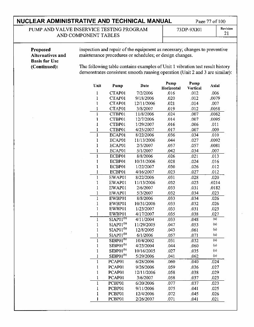
NUCLEAR ADMINISTRATIVE AND TECHNICAL MANUAL Page 77 of 100
PUMP AND VALVE INSERVICE TESTING PROGRAM 73DP-9XI01 Revision
AND COMPONENT TABLES 21
ProposedAlternatives andBasis for Use(Continued):
inspection and repair of the equipment as necessary; changes to preventivemaintenance procedures or schedules; or design changes.
The following table contains examples of Unit 1 vibration test result historydemonstrates consistent smooth running operation (Unit 2 and 3 are similar):
Unit1111
Pump
CTAP01CTAPO1CTAPO1CTAPO1
Date
7/2/20069/18/200612/11/20063/8/2007
PumpHorizontal
.016
.020
.021
.019
PumpVertical
.012
.012
.014
.012
Axial
.006.0079.007
.00581 CTBPO1 11/8/2006 .024 .007 .00821 CTBPO1 12/7/2006 .014 .007 .00951 CTBPO1 1/29/2007 .016 .006 .0111 CTBPO1 4/25/2007 .017 .007 .0091 ECAP01 8/22/2006 .036 .034 .0101 ECAP01 11/13/2006 .044 .027 .00921 ECAP01 2/5/2007 .057 .057 .00811 ECAP01 5/1/2007 .042 .034 .0071 ECBPO1 8/8/2006 .026 .021 .0131 ECBP01 10/31/2006 .028 .024 .0161 ECBP01 1/22/2007 .030 .026 .0121 ECBP01 4/16/2007 .023 .027 .0121 EWAP01 8/22/2006 .031 .028 .0201 EWAP01 11/13/2006 .032 .023 .02141 EWAP01 2/6/2007 .033 .031 .01821 EWAP01 5/3/2007 .032 .034 .0231 EWBPO1 8/8/2006 .033 .034 .0261 EWBP01 10/31/2006 .033 .032 .0261 EWBP01 1/23/2007 .033 .031 .0231 EWBP01 4/17/2007 .035 .038 .0271 SIAP01(b) 4/11/2004 .033 .048 (a)
1 SIAPO1(b) 11/29/2005 .047 .053 (a)
I SIAPOl(b) 12/8/2005 .043 .061 (a)
1 SIAP01(b) 6/1/2006 .057 .071 (a)
1 SIBP01(b) 10/4/2002 .031 .032 (a)
1 SIBPO1(b) 4/23/2004 .044 .060 (a)
1 SIBP01(b) 10/16/2005 .027 .035 (a)
1 SIBPo1,b) 5/29/2006 .041 .062 (a)
1 PCAP01 6/28/2006 .060 .040 .0241 PCAP01 9/26/2006 .059 .036 .0271 PCAP01 12/11/2006 .058 .038 .0291 PCAP01 3/6/2007 .058 .037 .0231 PCBP01 6/20/2006 .077 .037 .0231 PCBP01 9/11/2006 .075 .041 .0251 PCBP01 12/4/2006 .072 .045 .0261 PCBPO1 2/26/2007 .071 .041 .021

NUCLEAR ADMINISTRATIVE AND TECHNICAL MANUAL Page 78 of 100
PUMP AND VALVE INSERVICE TESTING PROGRAM 73DP-9XI01 Revision
AND COMPONENT TABLES 21
ProposedAlternatives andBasis for Use(Continued):
Unit11
1
Pump
SPAPO1(b)
SPAP0 1(b)
SPAP0 1(b)
SPAPO1(b)
Date
8/22/200611/14/20062/6/20075/3/2007
PumpHorizontal
.049
.052
.055
.049
PumpVertical
.027
.023
.027
.027
Axial
.0275
.0270
.0250
.02831 SPBPO1(b) 8/7/2006 .092 .047 .02611 SPBPO1(b) 11/1/2006 .088 .027 .02401 SPBPO1(b) 1/23/2007 .090 .030 .0291 SPBP01(b) 4/19/2007 .088 .035 .026
(a) - Inaccessible (b) - vibration readings taken at the motor-
Conclusion: 10 CFR 50.55a(a)(3) states:
"Proposed alternatives to the requirements of paragraphs (c), (d), (e), (f), (g),and (h) of this section or portions thereof may be used when authorized by theDirector of the Office of Nuclear Reactor Regulation. The applicant shalldemonstrate that:
(i)The proposed alternatives would provide an acceptable level of quality andsafety, or(ii)Compliance with the specified requirements of this section would result inhardship or unusual difficulty without a compensating increase in the level ofquality and safety."
The revised Alert and Required Action values discussed in this relief requestprovides an acceptable level of quality and safety. Therefore, APS requeststhat the proposed alternative be authorized pursuant to 10 CFR50.55a(a)(3)(i). Q
The proposed alternative identified in this 1 OCFR50.55a Request shall beutilized during the Third 10-Year IST Interval.
Relief Request PRR-07 was previously authorized for Palo Verde as ReliefRequest PRR-08 pursuant to 10 CFR 50.55a(a)(3)(i) for Interval 2 in the NRCSafety Evaluation dated July 8, 1999. (TAC NOS. MA0757, MA0758 andMA0759) (ADAMS Accession No. 9907150128)
Duration ofProposedAlternatives:
Precedents:

NUCLEAR ADMINISTRATIVE AND TECHNICAL MANUAL Page 79 of 100
PUMP AND VALVE INSERVICE TESTING PROGRAM 73DP-9XI01 Revision
AND COMPONENT TABLES 21
Cold Shutdown Justification No. 1 (CSJ-01)AFW Discharge Header Check Valve Open Exercising
Valve ID Valve Description Code Category Drawing / Coord.Class
AFAVO 15 AFW Pump AFA-P01 Discharge 3 C AFP-001 / E05Header Check Valve
AFBV024 AFW Pump AFB-PO1 Discharge 3 C AFP-001 / C05Header Check Valve
Function These check valves open to provide flowpaths from the respective auxiliaryfeedwater pump to the auxiliary feedwater headers. They close so that if onepump fails to start after an auxiliary feedwater actuation signal (AFAS), flowfrom the operating pump is not diverted back through the idle pump.
Alternate These valves will be full-stroke exercised open during cold shutdown periods.Testing
Basis These are simple check valves with no external means of exercising or fordetermining disc position. Full-stroke exercising open during plant operation isnot practical because this would inject cold auxiliary feedwater into the mainfeedwater lines. The resulting temperature perturbations could lead tounnecessary thermal shock / fatigue damage to the feedwater piping and steamgenerators, and the cooldown of the reactor coolant system could causeundesirable reactivity variations and power fluctuations.
This CSJ is similar to CSJ-3 in the second interval IST Program and CSJ-2 inthe first interval IST Program.
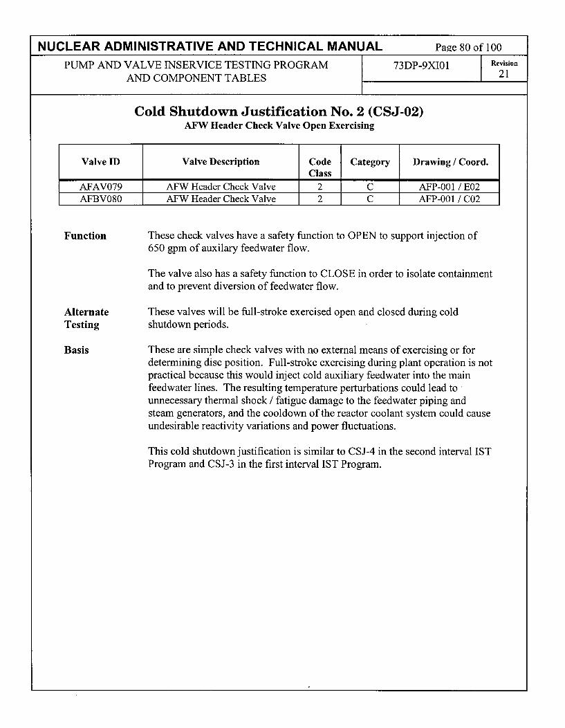
NUCLEAR ADMINISTRATIVE AND TECHNICAL MANUAL Page 80 of 100
PUMP AND VALVE INSERVICE TESTING PROGRAM 73DP-9XI01 Revision
AND COMPONENT TABLES 21
Cold Shutdown Justification No. 2 (CSJ-02)AFW Header Check Valve Open Exercising
Valve ID Valve Description Code Category Drawing / Coord.Class
AFAV079 AFW Header Check Valve 2 C AFP-001 / E02AFBV080 AFW Header Check Valve 2 C AFP-001 / C02
Function These check valves have a safety function to OPEN to support injection of650 gpm of auxilary feedwater flow.
The valve also has a safety function to CLOSE in order to isolate containmentand to prevent diversion of feedwater flow.
Alternate These valves will be full-stroke exercised open and closed during coldTesting shutdown periods.
Basis These are simple check valves with no external means of exercising or fordetermining disc position. Full-stroke exercising during plant operation is notpractical because this would inject cold auxiliary feedwater into the mainfeedwater lines. The resulting temperature perturbations could lead tounnecessary thermal shock / fatigue damage to the feedwater piping andsteam generators, and the cooldown of the reactor coolant system could causeundesirable reactivity variations and power fluctuations.
This cold shutdown justification is similar to CSJ-4 in the second interval ISTProgram and CSJ-3 in the first interval IST Program.

NUCLEAR ADMINISTRATIVE AND TECHNICAL MANUAL Page 81 of 100
PUMP AND VALVE INSERVICE TESTING PROGRAM 73DP-9XI01 Revision
AND COMPONENT TABLES 21
Cold Shutdown Justification No. 3 (CSJ-03)Auxiliary Pressurizer Spray Valve Exercising
Valve ID Valve Description Code Category Drawing / Coord.Class
CHBHV0203 Auxiliary Pressurizer Spray 1 B CHP-001 / H1OIsolation Valve
CHAHV0205 Auxiliary Pressurizer Spray I B CHP-001 / 1111Isolation Valve
Function These valves have an open safety function to provide flow from the chargingpump discharge header to the pressurizer for auxiliary pressurizer spray and aclose safety function for spray/pressure control.
Alternate The auxiliary pressurizer spray isolation valves will be full-stroke exercisedTesting open and closed during cold shutdown periods. Stroke time testing and fail-
safe testing will be performed in conjunction with exercise tests.
Basis Opening of the auxiliary pressurizer spray isolation valves during plantoperation initiates spray flow to the pressurizer. This could cause an RCSpressure transient that could adversely affect plant safety and lead to a planttrip. In addition, the pressurizer spray piping and nozzle would be subjectedto unnecessary thermal shock. Opening these valves during plant operation isconsidered impractical for these reasons.
This cold shutdown justification is similar to CSJ-6 in the second interval ISTProgram and CSJ-6 in the first interval IST Program.

NUCLEAR ADMINISTRATIVE AND TECHNICAL MANUAL Page 82 of 100
PUMP AND VALVE INSERVICE TESTING PROGRAM 73DP-9XI01 Revision
AND COMPONENT TABLES 21
Cold Shutdown Justification No. 4 (CSJ-04)Letdown Isolation Valve Closed Exercising
Valve ID Valve Description Code Category Drawing / Coord.Class
CHBUV0515 Reactor Coolant Letdown Isolation 1 B CHP-001 / H15Valve
CHAUV0516 Reactor Coolant Letdown Inbd. 1 A CHP-001 / G15Isolation Valve
CHBUV0523 Reactor Coolant Letdown Otbd. 1 A CHP-001 / F13Isolation Valve
Function These valves open to provide a flowpath for reactor coolant letdown flow -non-safety function. CHBUV0515 and CHAUV0516 have a closed safetyfunction to secure letdown on a Safety Injection Actuation signal (SIAS).CHAUV0516 and CHBUV0523 have a safety function to close on aContainment Isolation Actuation signal (CIAS) signal for containmentisolation.
Alternate These valves will be full-stroke exercised closed during cold shutdownTesting periods. Stroke time testing and fail-safe testing will be performed in
conjunction with exercise test.
Basis Closing any of these valves isolates the letdown line from the RCS. Duringplant operation, this would result in undesirable pressurizer level transientswith the potential for a plant trip. If a valve failed to reopen, then a plantshutdown may be required.
This cold shutdown justification is similar to CSJ-9 in the second interval ISTProgram and CSJ-8 in the first interval IST Program.

NUCLEAR ADMINISTRATIVE AND TECHNICAL MANUAL Page 83 of 100
PUMP AND VALVE INSERVICE TESTING PROGRAM 73DP-9XI01 Revision
AND COMPONENT TABLES 21
Cold Shutdown Justification No. 5 (CSJ-05)Shutdown Cooling Suction Isolation Valve Exercising
Valve ID Valve Description Code Category Drawing / Coord.Class
Shutdown Cooling Suction Inboard 1 A SIP-002 / D03Containment Isolation Valve
Shutdown Cooling Suction Inboard 1 A SIP-002 / D10Containment Isolation Valve
Function These valves have a normally closed safety function to ensure the integrity ofthe reactor coolant system and to provide containment isolation. They havean open safety function during plant cooldown to initiate shutdown cooling.
Alternate Each of these valves will be full-stroke exercised open and closed during coldTesting shutdown periods. Stroke time testing will be performed in conjunction with
the exercise testing.
Basis These valves provide pressure barriers between the reactor coolant systempressure and the lesser rated shutdown cooling piping systems. As aninstalled safety feature they are provided with electrical interlocks thatprevent them from being opened when pressurizer pressure is greater than 400psig. Although this interlock can be overridden, routine operation of thesevalves with a large differential pressure across the seats is consideredimpractical due to the risk of damage to the seating surfaces of the valves.
This cold shutdown justification is similar to CSJ-27 in the second intervalIST Program,
This cold shutdown justification is similar to CSJ-24 in the first interval ISTProgram, except that Valves SIAHV065 1, SIBHV0652, SIAUV0655 andSIB-UV0656 have been deleted from that CSJ due to the implementation ofASME OM Code Case OMN-1 per VRR-12.

NUCLEAR ADMINISTRATIVE AND TECHNICAL MANUAL Page 84 of 100
PUMP AND VALVE INSERVICE TESTING PROGRAM 73DP-9XI01 Revision
AND COMPONENT TABLES 21
Cold Shutdown Justification No. 6 (CSJ-06)Instrument Air Containment Isolation Valve Closed Exercising
Valve ID Valve Description Code Category Drawing / Coord.Class
IAAUVO002 Instrument Air Supply To 2 A IAP-003 / G07Containment Isolation Valve
Function This valve opens to provide flow for instrument air to the containment - non-safety function. The valve has a closed safety function to providecontainment isolation.
Alternate IAAUVO002 will be full-stroke exercised closed during cold shutdownTesting periods. Stroke time testing and fail-safe testing will be performed in
conjunction with exercise testing.
Basis Closing this valve during plant operation isolates instrument air to importantequipment within the containment building, including the pressurizer spraycontrol valves and letdown isolation valves. This would, in turn, riskpressurizer level and pressure transients with a potential for a plant trip. IfIAAUVO002 were to fail to re-open, an expedited plant shutdown would berequired.
This cold shutdown justification is similar to CSJ-13 in the second intervalIST Program and CSJ-13 and CSJ-14 in the first interval IST Program.

NUCLEAR ADMINISTRATIVE AND TECHNICAL MANUAL Page 85 of 100
PUMP AND VALVE INSERVICE TESTING PROGRAM 73DP-9XI01 Revision
AND COMPONENT TABLES 21
Cold Shutdown Justification No. 7 (CSJ-07)Reactor Head Vent and Pressurizer Vent Valve Exercising
Valve ID Valve Description Code Category Drawing / Coord.Class
RCAHV0101 Reactor Vessel Vent Valve 2 B RCP-001 / G15RCBHV0102 Reactor Vessel Vent Valve 2 B RCP-001 / G 15RCAHV0103 Pressurizer Vent Valve 2 B RCP-001 / G14RCBHV0105 Reactor Coolant System Common 2 B RCP-001 / G13
Vent Valve To RDTRCAHV0106 Reactor Coolant System Common 2 B RCP-001 / G13
Vent Valve To ContainmentRCBHV0108 Pressurizer Vent Valve 2 B RCP-001 / G 13RCBHV0109 Pressurizer Vent Valve 2 B RCP-001 / G 13
Function These valves have an open safety function to remotely vent non-condensiblegasses from the reactor vessel and/or pressurizer steam space. They can alsobe used to depressurize the RCS. They have a safety function to close forreactor coolant system integrity.
Alternate These valves will be full-stroke exercised open and closed during coldTesting shutdown periods. Stroke time testing and fail-safe testing will be performed
in conjunction with the exercise testing.
Basis These valves are administratively controlled in the keylocked closed positionwith the power supply disconnected to prevent inadvertent operation. Sincethese are reactor coolant system boundary valves, failure of a valve to close orsignificant RCS leakage following closure can result in a loss of coolant inexcess of the limits imposed by the Technical Specifications leading to a plantshutdown. Furthermore, if a valve were to fail open or valve indication fail toshow the valve returned to the fully closed position after exercising, it islikely that a plant shutdown would be required. Note also that TechnicalSpecifications require that these valves be closed in Modes 1-4.
This cold shutdown justification is similar to CSJ-15 in the second intervalIST Program and CSJ-16 in the first interval IST Program.

NUCLEAR ADMINISTRATIVE AND TECHNICAL MANUAL Page 86 of 100
PUMP AND VALVE INSERVICE TESTING PROGRAM 73DP-9Xi01 Revision
AND COMPONENT TABLES 21
Cold Shutdown Justification No. 8 (CSJ-08)Feedwater Isolation Valve Closed Exercising
Valve ID Valve Description Code Category Drawing / Coord.Class
SGBUVO 130 Inbd. FWIV to SG #1 Downcomer 2 B SGP-002 / G11SGBUVO132 Inbd. FWIV to SG #1 Economizer 2 B SGP-002 / E12SGBUV0135 Inbd. FWIV to SG #2 Downcomer 2 B SGP-002 / C ISGBUV0137 Inbd. FWIV to SG #2 Economizer 2 B SGP-002 / A12SGAUVO172 Otbd. FWIV to SG #1 Downcomer 2 B SGP-002 / G12SGAUVO174 Otbd. FWIV to SG #1 Economizer 2 B SGP-002 / E12SGAUV0175 Otbd. FWIV to SG #2 Downcomer 2 B SGP-002 / C 12SGAUV0177 Otbd. FWIV to SG #2 Economizer 2 B SGP-002 / A12
Function The main feedwater isolation valves (FWIVs) are normally open duringsteaming operations to provide flowpaths for main feedwater flow to thesteam generators - non-safety function. They have a closed safety function toisolate and maintain the integrity of the steam generators and to securefeeding a faulted steam generator in the event of a steam leak insidecontainment.
Alternate Each of these valves will be full-stroke exercised closed during cold shutdownTesting periods. Stroke time testing and fail-safe testing will be performed in
conjunction with the exercise testing.
Basis Closing any of these valves isolates the associated feedwater header. Duringplant operation, isolation of a feedwater header would require a significantpower reduction and could result in unacceptable steam generator level andreactor power transients with the potential for a plant trip.
The downcomer isolation valves do not have partial-stroke capability,however the economizer isolation valves are capable of partial strokeexercising. Part-stroke exercising is not considered practical because of therisk of full closure. This risk was recognized by NUREG-1432, Vol 1, Rev.1, "Standard Technical Specifications - Combustion Engineering PlantsSpecifications", which states that "MFIVs should not be tested at power sinceeven a part stroke exercise increases the risk of a valve closure with the unitgenerating power" as the basis for the 18-month test frequency specified bySR 3.7.3.1. Nevertheless, part-stroke exercising continues to be performed asan augmented test to satisfy System and Maintenance Engineering's desire toperiodically exercise the 4-way pilot valves to confirm continued operability.
This cold shutdown justification is similar to CSJ-l18 in the second intervalIST Program and CSJ-17 and CSJ-26 in the first interval IST Program.

NUCLEAR ADMINISTRATIVE AND TECHNICAL MANUAL Page 87 of 100
PUMP AND VALVE INSERVICE TESTING PROGRAM 73DP-9XI01 Revision
AND COMPONENT TABLES 21
Cold Shutdown Justification No. 9 (CSJ-09)Main Steam Isolation Valve Closed Exercising
Valve ID Valve Description Code Category Drawing / Coord.Class
SGEUVO170 Main Steam Isolation Valve From 2 B SGP-001, Sh. I / G10Steam Gen. #1 1
SGEUV0171 Main Steam Isolation Valve From 2 B SGP-001, Sh. 1 / D 10Steam Gen. #2
SGEUV0180 Main Steam Isolation Valve From 2 B SGP-001, Sh. 1 / F10Steam Gen. #1
SGEUV0181 Main Steam Isolation Valve From 2 B SGP-001, Sh. 1 / B 10Steam Gen. #2 1 1 1
Function These valves are normally open during steaming operations to provideflowpaths for steam flow to the main turbine generators and associatedauxiliaries - non-safety function. They have a closed safety functionn toisolate and maintain the integrity of the steam generators.
Alternate Each of these valves will be full-stroke exercised closed during cold shutdownTesting periods. Stroke time testing and fail-safe testing will be performed in
conjunction with exercise testing.
Basis Closing any of these valves isolates the associated steam header. During plantoperations, isolation of a main steam header would require a significant powerreduction and could result in unacceptable steam generator level and reactorpower transients with the potential for a plant trip.
The main steam isolation valves are capable of partial stroke exercising. Part-stroke exercising is not considered practical because of the risk of closure.This risk was recognized by NUREG-1432, Vol 1, Rev. 1, "StandardTechnical Specifications - Combustion Engineering Plants Specifications",which states that "MSIVs should not be tested at power since even a partstroke exercise increases the risk of a valve closure with the unit generatingpower" as the basis for the 18-month test frequency specified by SR 3.7.2.1.Nevertheless, part-stroke exercising continues to be performed as anaugmented test to satisfy System and Maintenance Engineering's desire toperiodically exercise the 4-way pilot valves to confirm continued operability.
This cold shutdown justification is similar to CSJ-19 in the second intervalIST Program and CSJ-25 in the first interval IST Program.

NUCLEAR ADMINISTRATIVE AND TECHNICAL MANUAL Page 88 of 100
PUMP AND VALVE INSERVICE TESTING PROGRAM 73DP-9XI01 Revision
AND COMPONENT TABLES 21
Cold Shutdown Justification No. 10 (CSJ-10)SIT Vent Valve Exercising
Valve ID Valve Description Code Category Drawing / Coord.Class
SIAHV0605 Safety Inj. Tank 2A Vent Valve 2 B SIP-002 / F 15SIAHV0606 Safety Inj. Tank 2B Vent Valve 2 B SIP-002 / F12SIAHV0607 Safety Inj. Tank lA Vent Valve 2 B SIP-002 / F07SLAHV0608 Safety Inj. Tank lB Vent Valve 2 B SIP-002 / F04SIBHV0613 Safety Inj. Tank 2A Vent Valve 2 B SIP-002 / E15SIBHV0623 Safety Inj. Tank 2B Vent Valve 2 B SIP-002 / E12SIBHV0633 Safety Inj. Tank 1AVent Valve 2 B SIP-002 / E07SIBHVO643 Safety Inj. Tank 1B Vent Valve 2 B SIP-002 / E04
Function These valves have a normally closed safety function to ensure the integrity ofthe associated safety injection tank (SIT) so that the required nitrogenoverpressure is maintained. They have an open safety function to reduce thenitrogen pressure in the SITs during RCS depressurization to precludenitrogen injection into the RCS.
Alternate Each of these valves will be exercised open and closed during cold shutdownTesting periods. Stroke time testing and fail-safe testing will be performed in
conjunction with exercise testing.
Basis These valves are normally closed during plant operation. Plant technicalspecifications require that power be removed from the valves, and that the SITnitrogen cover gas pressure be maintained within the required range.Exercising a valve during operation would render the associated SITinoperable if the cover gas pressure were reduced below the required range.A valve failing open during testing would completely depressurize the SITand result in an expedited plant shutdown.
This cold shutdown justification is similar to CSJ-26 in the second intervalIST Program and CSJ-22 in the first interval IST Program.
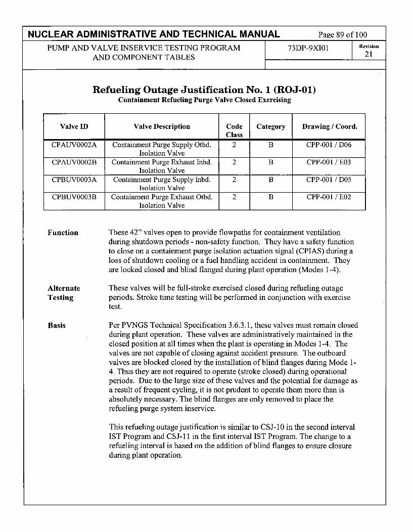
NUCLEAR ADMINISTRATIVE AND TECHNICAL MANUAL Page 89 of 100
PUMP AND VALVE INSERVICE TESTING PROGRAM 73DP-9XI01 Revision
AND COMPONENT TABLES 21
Refueling Outage Justification No. 1 (ROJ-01)Containment Refueling Purge Valve Closed Exercising
Valve ID Valve Description Code Category Drawing / Coord.Class
CPAUVO002A Containment Purge Supply Otbd. 2 B CPP-001 / D06Isolation Valve
CPAUVO002B Containment Purge Exhaust Inbd. 2 B CPP-001 / E03Isolation Valve
CPBUVO003A Containment Purge Supply Inbd. 2 B CPP-001 / D05Isolation Valve
CPBUVO003B Containment Purge Exhaust Otbd. 2 B CPP-001 / E02Isolation Valve
Function These 42" valves open to provide flowpaths for containment ventilationduring shutdown periods - non-safety function. They have a safety functionto close on a containment purge isolation actuation signal (CPIAS) during aloss of shutdown cooling or a fuel handling accident in containment. Theyare locked closed and blind flanged during plant operation (Modes 1-4).
Alternate These valves will be full-stroke exercised closed during refueling outageTesting periods. Stroke time testing will be performed in conjunction with exercise
test.
Basis Per PVNGS Technical Specification 3.6.3.1, these valves must remain closedduring plant operation. These valves are administratively maintained in theclosed position at all times when the plant is operating in Modes 1-4. Thevalves are not capable of closing against accident pressure. The outboardvalves are blocked closed by the installation of blind flanges during Mode 1-4. Thus they are not required to operate (stroke closed) during operationalperiods. Due to the large size of these valves and the potential for damage asa result of frequent cycling, it is not prudent to operate them more than isabsolutely necessary. The blind flanges are only removed to place therefueling purge system inservice.
This refueling outage justification is similar to CSJ-10 in the second intervalIST Program and CSJ- 11 in the first interval IST Program. The change to arefueling interval is based on the addition of blind flanges to ensure closureduring plant operation.

NUCLEAR ADMINISTRATIVE AND TECHNICAL MANUAL Page 90 of 100
PUMP AND VALVE INSERVICE TESTING PROGRAM 73DP-9XI01 Revision
AND COMPONENT TABLES 21
Refueling Outage Justification No. 2 (ROJ-02)RCP Seal Bleed-Off Isolation Valve Closed Exercising
Valve ID Valve Description Code Category Drawing / Coord.Class
CHBUV0505 Reactor Coolant Pump Seal Bleed- 2 A CHP-002 / H13off Otbd. Isolation Valve
CHAUV0506 Reactor Coolant Pump Seal Bleed- 2 A CHP-002 / H14off Inbd. Isolation Valve I I I _I
Function These valves are normally open during plant operation to provide a flowpathfor seal bleed-off from the reactor coolant pumps (RCPs) - non-safetyfunction. They have a closed safety function for containment isolation.
Alternate These valves will be exercised closed during refueling outage periods. StrokeTesting time testing and fail safe testing will be performed in conjunction with
exercise testing.
Basis These air-operated valves are electrically interlocked so that they cannot beclosed when any of the reactor coolant pumps are in operation. Closing eitherof these valves during RCP operation would interrupt bleed-off flow from theRCP seals and could result in damage to the seals. Thus testing these valvesduring plant operation would require the unnecessary shutdown of all of thereactor coolant pumps.
Operation of seal injection is also maintained during cold shutdown periods.
It is noted that paragraph 3.1.1.4 of NUREG-1482, Revision 1, permitsdeferral of tests that require shutdown of RCPs until refueling outages.
This refueling outage justification is similar to CSJ-32 in the second intervalIST Program and CSJ-7 in the first interval IST Program. The change to arefueling outage interval is based on seal injection being used during coldshutdown periods.

NUCLEAR ADMINISTRATIVE AND TECHNICAL MANUAL Page 91 of 100
PUMP AND VALVE INSERVICE TESTING PROGRAM 73DP-9XI01 Revision
AND COMPONENT TABLES 21
VALVE RELIEF REQUEST VRR-01Proposed Alternative In Accordance with 10CFR50.55a(a)(3)(i)
On the basis that the proposed alternative provides an acceptable level of quality and safety.
Code Case OMN-1 - MOV Exercising and Stroke Timing
Component(s)Affected:
Component/SystemFunction:
Applicable CodeEdition and Addenda:
Applicable CodeRequirement(s):
Motor-operated valve assemblies currently included in the PaloVerde Nuclear Generating Station (PVNGS) Motor-Operated ValveProgram
Various
ASME OM Code 2001 Edition w/2003 Addenda
ISTA-3130, "Application of Codes Cases", ISTA-3130(b) states,Code Cases shall be applicable to the edition and addenda specifiedin the test plan.
ISTC-3500, "Valve Testing Requirements" states; Active andpassive valves in the categories defined in ISTC-1300 shall be testedin accordance with the paragraphs specified in Table ISTC-3500-1and the applicable requirements of ISTC-5 100 and ISTC-5200.
ISTC-3700, "Position Verification Testing" states; Valves withremote position indicators shall be observed locally at least onceevery 2 years to verify the valve operation is accurately indicated.
ISTC-5120, "Motor-Operated Valves", ISTC-5121 (a) states; Activevalves shall have their stroke times measured when exercised inaccordance with ISTC-3500.
Code Case OMN- 1, Revision 0 provides alternative rules to those ofOM Code, Subsection ISTC, for preservice and inservice testing toassess the operational readiness of certain electric motor-operatedvalve assemblies in light-water reactor power plants. However, RG1.192 has not yet extended its use to the 2001 Edition w/2003Addenda of the OM Code which is the basis for the planned third10-year IST program at Palo Verde.
Pursuant to ASME Code Case OMN-1 and the guidelines providedin NUREG-1482, Revision 1, Section 4.2.5, PVNGS proposes tocontinue implementation of Code Case OMN-1 in lieu of the stroke-time provisions specified in ISTC-5120 for MOVs. Code Case
Reason for Request:
Proposed Alternativesand Basis for Use:

NUCLEAR ADMINISTRATIVE AND TECHNICAL MANUAL Page 92 of 100
PUMP AND VALVE INSERVICE TESTING PROGRAM 73DP-9XI01 Revi ion
AND COMPONENT TABLES 21
Proposed Alternatives OMN- 1 has been determined by the NRC to provide an acceptableand Basis for Use: level of quality and safety when implemented in conjunction with the
conditions imposed in RG 1.192.(Continued)
The conditions specified in RG 1.192 are as follows:
Regulatory Guide 1.192, Operation and Maintenance Code CaseAcceptability, ASME OM Code, dated June 2003 states thatlicensees may use Code Case OMN-1, "Alternative Rules forPreservice and Inservice Testing of Certain Electric Motor-OperatedValve Assemblies in Light-Water Reactor Power Plants," Revision0, in lieu of the provisions for stroke-time testing in Subsection ISTCof the 1995 Edition up to and including the 2000 Addenda of theASME OM Code when applied in conjunction with the provisionsfor leakage rate testing in, as applicable, ISTC 4.3 (1995 Editionwith the 1996 and 1997 Addenda) and ISTC-3600 (1998 Editionwith the 1999 and 2000 Addenda). In addition, licensees whocontinue to implement Section XI of the ASME BPV Code as theirCode of Record may use OMNN-I in lieu of the provisions for stroke-time testing specified in Paragraph 4.2.1 of ASME/ANSI OM Part10 as required by 10 CFR 50.55a(b)(2)(vii) subject to the conditionsin this Regulatory Guide (RG) 1.192. Licensees who choose toapply OMN-1 are required to apply all its provisions.
The relevant provisions are as follows:
(1) The adequacy of the diagnostic test interval for each motor-operated valve (MOV) must be evaluated and adjusted asnecessary, but not later than 5 years or three refueling outages(whichever is longer) from initial implementation of OM7N-1.
(2) When extending exercise test intervals for high risk MOVsbeyond a quarterly frequency, licensees must ensure that thepotential increase in Core Damage Frequency (CDF) and riskassociated with the extension is small and consistent with theintent of the Commission's Safety Goal Policy Statement.
(3) When applying risk insights as part of the implementation ofOMN-1, licensees must categorize MOVs according to theirsafety significance using the methodology described in CodeCase OMN-3, "Requirements for Safety SignificanceCategorization of Components Using Risk Insights for InserviceTesting of LWR Power Plants," with the conditions discussed inRG 1.192 or use other MOV risk ranking methodologiesaccepted by the NRC on a plant specific or industry-wide basiswith the conditions in the applicable safety evaluations.

NUCLEAR ADMINISTRATIVE AND TECHNICAL MANUAL Page 93 of 100
PUMP AND VALVE INSERVICE TESTING PROGRAM 73DP-9XI01 Revision
AND COMPONENT TABLES 21
Proposed Alternativesand Basis for Use: In addition the following implementation clarifications are
necessary:(Continued) OMN-1, RO, Para. 3.1, Design Basis Verification Test
Design Basis Verification Testing was completed during plantstartup testing and in response to NRC GL 89-10 testingrequirements, which meet the intent of this CC requirement.
OMN-1, RO, Para. 3.2, Preservice TestingPreservice Testing was performed pursuant to NRC GL 89-10 testingrequirements, which meet the intent of this CC requirement.
OMN-1, RO, Para. 3.3 (b) Inservice TestBecause of the extensive PVNGS MOV performance history, someAs-Found MOV testing can be waived by a documented Engineeringevaluation, e.g., if a modification to the valve or actuator will beperformed or if valve maintenance is planned (such as valverepacking), and the activity will require a post maintenancediagnostic test to return the MOV to service. This provision will notapply if there is reason to suspect the MOV is not operating properlyprior to the maintenance activity.
OMN-1, RO, Para. 3.3 (c) Inservice TestPVNGS performed differential pressure testing per NRC GL 89-10and also participated in the JOG differential pressure testing program(i.e. dynamic testing) that has been completed. The mix of staticand dynamic testing at PVNGS in the future will be static testingwith additional dynamic testing performed as required by thePVNGS MOV Program to address MOV modifications.
OMN-1, RO, Para. 3.3.1, Inservice Test IntervalPVNGS has committed to the JOG program as part of its response toNRC GL 96-05. Inservice Test Intervals will be established basedon MOV margin and the valve's risk/safety significance inaccordance with JOG program requirements. PVNGS is currentlyimplementing the JOG Interim Test Program per MPR 1807.PVNGS will implement the final JOG Periodic Verification Programper MPR 2524-A as noted in the NRC SER on the JOG program.
OMN-1, RO, Para. 3.4 Effect of MOV Replacement, Repair, orMaintenanceDiagnostic test results within the MOV Program setpoint bands aresatisfactory and do not require analysis.

NUCLEAR ADMINISTRATIVE AND TECHNICAL MANUAL Page 94 of 100
PUMP AND VALVE INSERVICE TESTING PROGRAM 73DP-9XI01 Revision
AND COMPONENT TABLES 21
Proposed Alternatives OMN-1, RO, Para. 3.5 Grouping of MOVs for Inservice Testingand Basis for Use: PVNGS elects not to use Grouping of MOVs for Inservice Testing
(Continued) OMN-1, RO, Para. 3.7 Risk Basis Criteria for MOV TestingPVNGS is currently not planning to implement a Risk InformedProgram for its IST program. As noted above, PVNGS usesrisk/safety significance and MOV margin as part of the JOG programto establish MOV testing frequency.
OMN-1, RO, Para. 6.3 Evaluation of Data andPara. 6.4 Determination of MOV Functional MarginPVNGS utilizes the JOG Program criteria for determining MOV testfrequency. The MOV test frequencies have been established toensure MOV setpoints and MOV margins are maintained over theMOV test interval which meets the intent of these CC sections.
OMN-1, RO, Para. 6.4.1 Determination of Valve OperatingRequirementsA Stem Factor shall be determined for rising stem valves wheneverstem thrust and stem torque are measured. It is not possible tomeasure thrust and torque on all rising stem valves.
OMN-1, RO, Para. 6.4.2.1 Available Output Based on MotorCapabilities and CC OMN-1 Para. 6.4.2.2 Available Output Basedon Torque Switch SettingActuator output capabilities are determined as an integral part of theMOV design basis calculations and are not performed as part of theevaluation of MOV test data. This applies to all actuators andincludes those actuators set up based on limit switches.
For actuators set up based on torque switches, available outputincludes torque measurement uncertainty (or displacementuncertainty if spring pack displacement is used) and torque switchrepeatability.
OMN-1, RO, Para. 6.4.3 Calculation of Functional MarginMargin is calculated as a percentage (vice difference in thrust ortorque between available output and valve operating requirements).
OMN-1, RO, Para. 6.4.4 Determination of MOV Test IntervalAs noted above for CC OMN-1 Para 3.3.1, test interval is based onthe NRC approved JOG program.
OMN-1, RO, Para. 9.1 Test InformationTest Information relevant to the MOV being tested and relevant testparameters will be recorded electronically with the test trace and/or

NUCLEAR ADMINISTRATIVE AND TECHNICAL MANUAL Page 95 of 100PUMP AND VALVE INSERVICE TESTING PROGRAM 73DP-9XI01 Revision
AND COMPONENT TABLES 21
Proposed Alternatives on the test data sheet. MOV configuration data not directly relatedand Basis for Use: to testing, e.g., name plate information; breaker setting, etc. are
maintained in plant records.(Continued)
Code Case OMN-1, RO, should be considered acceptable for usewith OM Code-2001 Edition w/2003 Addenda as the Code of record.Therefore, pursuant to 10 CFR 50.55a(a)(3)(i), PVNGS requestsrelief from the specific ISTC Code requirements identified in thisrelief request.
Conclusion: 10 CFR 50.55a(a)(3) states:
"Proposed alternatives to the requirements of paragraphs (c), (d), (e),(f), (g), and (h) of this section or portions thereof may be used whenauthorized by the Director of the Office of Nuclear ReactorRegulation. The applicant shall demonstrate that:
(i)The proposed alternatives would provide an acceptable level ofquality and safety, or(ii)Compliance with the specified requirements of this section wouldresult in hardship or unusual difficulty without a compensatingincrease in the level of quality and safety."
The continued use of ASME Code Case OMN-1, Revision 0, asdiscussed in this relief request provides an acceptable level of qualityand safety. Therefore, APS requests that the proposed alternative beauthorized pursuant to 10 CFR 50.55a(a)(3)(i).
Duration of ProposedAlternatives: The proposed alternative identified in this relief request shall be
utilized during the Third Ten Year IST Interval.Precedents:
Relief Request VRR-01 was previously authorized for Palo Verde asRelief Request VRR-12 pursuant to 10 CFR 50.55a(a)(3)(i) forinterval 2 in the NRC Safety Evaluation dated July 8, 1999. (TACNOS. MA0757, MA0758 and MA0759) (ADAMS Accession No.9907150128)

NUCLEAR ADMINISTRATIVE AND TECHNICAL MANUAL Page 96 of 100
PUMP AND VALVE INSERVICE TESTING PROGRAM 73DP-9XI01 Revision
AND COMPONENT TABLES 21
References:
NUREG-1482, Revision 1, Section 4.2.5, "Alternatives to Stroke-Time Testing"
Regulatory Guide 1.192, "Operation and Maintenance Code CaseAcceptability, ASME OM Code", Table 2, "ConditionallyAcceptable OM Code Cases"
OM Code-2001 Edition w/2003 Addenda, Paragraph ISTC-5120,"Motor Operated Valves"
OM Code-2001 Edition w/2003 Addenda, Paragraph ISTA-3130,"Application of Code Cases"
Code Case OMN-1, "Alternative Rules for Preservice and InserviceTesting of Certain Electric Motor-Operated Valve Assemblies inLWR Power Plants"
Interval 2 NRC SER dated 7/8/1999

NUCLEAR ADMINISTRATIVE AND TECHNICAL MANUAL Paae 97 of 100
PUMP AND VALVE INSERVICE TESTING PROGRAM 73DP-9XI01 Revision
AND COMPONENT TABLES 21
Notes, Legends, Definitions, and Abbreviations
Notes
Note 1 Whenever check valve is disassembled for inspection, perform a manual exercise per73ST-9ZZ25.
Note 2 Manual exercise per 73ST-9ZZ25 can be substituted for the regular check valve
exercise test.
Note 3 Perform a partial stroke exercise with flow after reassembly, if practical.
Note 4 Check valve is tested under the PVNGS Check Valve Condition Monitoring Programand 73DP-9XI05.
Note 5 As provided for in ASME OM Code Case OMN-1, MOVs are tested in the PVNGS89-10 Program in lieu of the stroke time test and valve position verificationsurveillances that were performed in the past. This Code Case requires Active MOVsto be exercised once per fuel cycle (ICY). Additional exercising is performed at theLicensee's discretion (refer to VRR-01) as delineated in the component tables. Postmaintenance retest requirements for MOVs are specified in 39DP-9ZZ04 Appendix G.
Note 6 A 42-inch refueling purge valve is not a required containment isolation valve when itsflow path is isolated with a blind flange tested in accordance with TS SR 3.6.1.1 (TSLCO 3.6.3 Note 5)
Pump Table Legend
Pump ID Plant equipment identifier. The first 2 letters in the ID indicate the system.
Description Name / description of the pump
Code Class ISI classification of the pump: 1, 2, 3, or N (non-class)
Drawing / Coord. Piping and Instrument Diagram number and coordinates showing the pump
Test Parameters The table indicates the frequency which pump speed, pressure, flow rate,and vibration are measured, along with any applicable relief requests
Test Procedure Procedure(s) which satisfy the testing requirements
Remarks Additional explanation or clarification, if required
Valve Table Legend
Valve ID Plant equipment identifier. The first 2 letters in the ID indicate the system.
Description Name / description of the valve
Drawing Piping and Instrument Diagram number showing the valve
Coord Coordinates where the valve is located on the drawing
Sht# Drawing sheet number

NUCLEAR ADMINISTRATIVE AND TECHNICAL MANUAL Paae 98 of 100
PUMP AND VALVE INSERVICE TESTING PROGRAM 73DP-9XI01 Revision
AND COMPONENT TABLES 21
Code Class ISI classification of the valve: 1, 2, 3, or N (non-class)
Size Nominal pipe size of the valve, in inches
Type Valve type:BF Butterfly ValveCK Check ValveDI Diaphragm valveGA Gate ValveGL Globe ValvePSV Pressure Safety Relief ValveRD Rupture DiskVR Vacuum Relief
Act. Valve actuator type:AO Air OperatedHY Hydraulically OperatedMA Manually OperatedMO Motor OperatedSA Self ActuatingSO Solenoid Operated
Cat. A, B, C, or D, per ISTC-1300, "Valve Categories"
A/P A (active) or P (passive) valve, per ISTA-2000, "Definitions."
S.P. Safety position: 0 (open), C (closed), or OC (both open and closed).
Test Test(s) performed on the valve. The first two letters indicate the type oftest:
AJ Appendix J Leak TestBD Bi-Directional Check Valve Test (non-safety direction)CV Check Valve Test (safety function direction)FS Full Stroke Exercise TestFT Fail Safe TestLT Leak Test other than an Appendix J TestPS Partial Stroke Exercise TestREP ReplacementST Stroke Time TestSV Pressure Safety Relief Valve TestVP Valve Position Indication Test
A third letter is used where required to indicate stroke direction: 0 (open)or C (closed), or a special activity, like I (inspection).

NUCLEAR ADMINISTRATIVE AND TECHNICAL MANUAL Page 99 of 100PUMP AND VALVE INSERVICE TESTING PROGRAM 73DP-9XI01 Revision
AND COMPONENT TABLES 21
Freq Frequency at which a test is performed:CLR Per the Containment Leak Rate ProgramCMP Per the Check Valve Condition Monitoring ProgramCSD Cold Shut DownQTR QuarterlyRFO Refueling OutageSTF Special Test Frequency6M Once per 6-months1YR Once per year18M Once per 18 months1CY Once per fuel cycle2YR Once every 2 years5YR Mandatory Appendix 1-1320 (at least once every 5 years)10Y Mandatory Appendix 1-1350 (at least once every 10 years)
Procedure Procedure in which the test is performed
CSJ/ROJ/VRR Applicable Cold Shutdown Justification, Refueling Outage Justification, orValve Relief Request
Remarks Additional explanation or clarification, if required
Definitions
Augmented Components or tests included within the IST Program at the discretion ofIST Engineering. Augmented components are generally tested inaccordance with the Code to the extent practical; however, deviations fromCode requirements do not require relief.
AbbreviationsACU Air Conditioning Unit
AF Auxiliary Feedwater system
AFAS Auxiliary Feedwater Actuation Signal
AFW Auxiliary Feedwater
ANII Authorized Nuclear Inservice Inspector
AOV Air-Operated Valve
ASME American Society of MechanicalEngineers
BAMP Boric Acid Makeup Pump
CC Code Case
CEDM Control Element Drive Mechanism
CH Charging system
CIAS Containment Isolation Actuation Signal
CIV
CP
CPIAS
CS
CSD
CsJ
CST
CT
DF
DG
DW
EC
Containment Isolation Valve
Containment Purge system
Containment Purge Isolation ActuationSignal
Containment Spray
Cold Shutdown
Cold Shutdown Justification
Condensate Storage Tank
Condensate Transfer system
Diesel Fuel system
Diesel Generator system
Demineralized Water system
Essential Chilled Water system

NUCLEAR ADMINISTRATIVE AND TECHNICAL MANUAL Page 100 of 100
PUMP AND VALVE INSERVICE TESTING PROGRAM 73DP-9XI01 Revision
AND COMPONENT TABLES 21
EDG
ESF
EW
FP
FWIV
GA
GL
GR
H2
HC
HP
HPSI
HVAC
IA
ISl
IST
LCO
LOCA
LPSI
LTOP
MFIV
MOV
MSIV
NC
PASS
PC
PEN.
PRA/RA
PRR
PVNGS
RC
RCP
RCS
RD
Emergency Diesel Generator
Engineered Safety Features
Essential Cooling Water system
Fire Protection system
Feedwater Isolation Valve
Service Gas system
Generic Letter
Gaseous Radwaste system
Hydrogen
Containment HVAC system
Hydrogen Purge system
High Pressure Safety Injection
Heating, ventilation, and air conditioning
Instrument Air system
Inservice Inspection
Inservice Testing
Limiting Condition for Operation
Loss of Coolant Accident
Low Pressure Safety Injection
Low Temperature Over Pressure
Main Feedwater Isolation Valve
Motor-Operated Valve
Main Steam Isolation Valve
Nuclear Cooling Water system
Post-Accident Sampling System
Fuel Pool Cooling
Penetration
Probablistic Risk Assessment/RiskAssessment
Pump Relief Request
Palo Verde Nuclear Generating Station
Reactor Coolant system
Reactor Coolant Pump
Reactor Coolant System
Radioactive Drains
RDT
RMW
ROJ
RWT
SDC
SG
SG
SI
SIAS
SIT
SOV
SP
SR
SS
TDAFW
TRM
TS
TSR
VCT
VRR
WC
Reactor Drain Tank
Reactor Makeup Water
Refueling Outage Justification
Refueling Water Tank
Shutdown Cooling
Steam Generator
Main Steam system
Safety Injection system
Safety Injection Actuation Signal
Safety Injection Tank
Solenoid-Operated Valve
Essential Spray Pond system
Surveillance Requirement
Sampling system
Turbine-Driven Auxiliary Feedwater Pump
Technical Requirements Manual
Technical Specification
TRM Surveillance Requirement
Volume Control Tank
Valve Relief Request
Normal Chilled Water system