
Palladium - Envirel
18
Palladium P-400 ORDERCODE D4131(B) P-500 ORDERCODE D4132(B) P-700 ORDERCODE D4133(B) P-900 ORDERCODE D4134(B) P-1200 ORDERCODE D4135(B) P-1600 ORDERCODE D4136(B) P-2000 ORDERCODE D4137(B) Highlite International B.V. Vestastraat 2 6468 EX Kerkrade The Netherlands Phone: +31 45-5667700
Transcript of Palladium - Envirel

Palladium P-400 ORDERCODE D4131(B)
P-500 ORDERCODE D4132(B)
P-700 ORDERCODE D4133(B)
P-900 ORDERCODE D4134(B)
P-1200 ORDERCODE D4135(B)
P-1600 ORDERCODE D4136(B)
P-2000 ORDERCODE D4137(B)
Highlite International B.V.
Vestastraat 2
6468 EX Kerkrade
The Netherlands
Phone: +31 45-5667700

1
Congratulations! You have bought a great, innovative product from DAP Audio.
The DAP Audio Palladium Series brings excitement to any venue. Whether you want simple plug-&-play
action or a sophisticated show, this product provides the effect you need.
You can rely on DAP Audio, for more excellent audio products.
We design and manufacture professional audio equipment for the entertainment industry.
New products are being launched regularly. We work hard to keep you, our customer, satisfied.
For more information: [email protected]
You can get some of the best quality, best priced products on the market from DAP Audio.
So next time, turn to DAP Audio for more great audio equipment.
Always get the best -- with DAP Audio !
Thank you!
2
DAP Audio
DAP Audio Palladium™ Product Guide
Warning ........................................................................................................................................................................... 3
Safety Instructions ..................................................................................................................................................... 3
Operating Determinations ....................................................................................................................................... 4
Return Procedure ...................................................................................................................................................... 5
Claims ......................................................................................................................................................................... 5
Description of the device ............................................................................................................................................. 6
Features ...................................................................................................................................................................... 6
Overview .................................................................................................................................................................... 6
Backside ..................................................................................................................................................................... 7
Installation ...................................................................................................................................................................... 8
Set Up and Operation ................................................................................................................................................... 8
Connection Inputs .................................................................................................................................................... 8
Connecting Outputs ................................................................................................................................................. 9
Connecting Power .................................................................................................................................................... 9
Stereo Operation ...................................................................................................................................................... 9
Parallel Operation ..................................................................................................................................................... 9
Bridged Mono Operation ...................................................................................................................................... 10
Switches and controls ............................................................................................................................................ 10
Input Attenuators ................................................................................................................................................ 10
Mode-Select-Switch ........................................................................................................................................... 10
Ground Lift Switch ............................................................................................................................................... 10
Indicators .................................................................................................................................................................. 10
Clip LED ................................................................................................................................................................ 10
Signal-LED ............................................................................................................................................................. 11
Protect LED .......................................................................................................................................................... 11
Power LED ............................................................................................................................................................ 11
Protection Features ................................................................................................................................................. 11
Short Circuit ......................................................................................................................................................... 11
DC Voltage Protection ...................................................................................................................................... 11
Subsonic Frequencies ........................................................................................................................................ 11
Turn-On/Turn-Off-Protection .............................................................................................................................. 11
Speaker-Protection ............................................................................................................................................ 11
Connection Cables ..................................................................................................................................................... 12
Maintenance ................................................................................................................................................................ 13
Replacing a Fuse..................................................................................................................................................... 13
Troubleshooting ........................................................................................................................................................... 13
Product Specification .................................................................................................................................................. 14
Wire Gauge Chart (Metric) ........................................................................................................................................ 15
Wire Gauge Chart (AWG: American Wire Gauge) ................................................................................................ 16
3
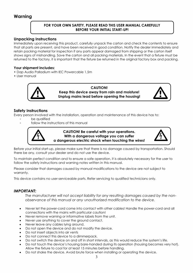
Warning
Unpacking Instructions Immediately upon receiving this product, carefully unpack the carton and check the contents to ensure
that all parts are present, and have been received in good condition. Notify the dealer immediately and
retain packing material for inspection if any parts appear damaged from shipping or the carton itself
shows signs of mishandling. Save the carton and all packing materials. In the event that a fixture must be
returned to the factory, it is important that the fixture be returned in the original factory box and packing.
Your shipment includes: • Dap Audio Palladium with IEC Powercable 1,5m
• User manual
Safety Instructions Every person involved with the installation, operation and maintenance of this device has to:
- be qualified
- follow the instructions of this manual
Before your initial start-up, please make sure that there is no damage caused by transportation. Should
there be any, consult your dealer and do not use the device.
To maintain perfect condition and to ensure a safe operation, it is absolutely necessary for the user to
follow the safety instructions and warning notes written in this manual.
Please consider that damages caused by manual modifications to the device are not subject to
warranty.
This device contains no user-serviceable parts. Refer servicing to qualified technicians only.
IMPORTANT: The manufacturer will not accept liability for any resulting damages caused by the non-
observance of this manual or any unauthorized modification to the device.
Never let the power-cord come into contact with other cables! Handle the power-cord and all
connections with the mains with particular caution!
Never remove warning or informative labels from the unit.
Never use anything to cover the ground contact.
Never leave any cables lying around.
Do not open the device and do not modify the device.
Do not insert objects into air vents
Do not connect this device to a dimmerpack.
Do not switch the device on and off in short intervals, as this would reduce the system’s life.
Do not touch the device’s housing bare-handed during its operation (housing becomes very hot).
Allow the fixture to cool for at least 15 minutes before handling.
Do not shake the device. Avoid brute force when installing or operating the device.
CAUTION!
Keep this device away from rain and moisture!
Unplug mains lead before opening the housing!
CAUTION! Be careful with your operations.
With a dangerous voltage you can suffer
a dangerous electric shock when touching the wires!
FOR YOUR OWN SAFETY, PLEASE READ THIS USER MANUAL CAREFULLY
BEFORE YOUR INITIAL START-UP!
4
Only use device indoor, avoid contact with water or other liquids.
Only operate the fixture after having checked that the housing is firmly closed and all screws are
tightly fastened.
Only operate the device after having familiarized with its functions.
Avoid flames and do not put close to flammable liquids or gases.
Always disconnect power from the mains, when device is not used or before cleaning! Only
handle the power-cord by the plug. Never pull out the plug by tugging the power-cord.
Make sure that the device is not exposed to extreme heat, moisture or dust.
Make sure that the available voltage is not higher than stated on the rear panel.
Make sure that the power-cord is never crimped or damaged. Check the device and the power-
cord from time to time.
Make sure that there is sufficient room on all sides of the system for air circulation.
Make sure you don’t use the wrong kind of cables or defective cables.
Make sure that signals into the mixer are balanced, otherwise hum could be created.
Avoid ground loops! Always be sure to connect the power amps and the mixing console to the
same electrical circuit to ensure the same phase!
Please turn off the power switch, when changing the power cord or signal cable.
Make sure that the amplifier is turned down, before turning the power on or off. So you can avoid
supersonic frequencies, which could damage your speakers.
Make sure that the amplifier is turned down, before turning the power on or off. So you can avoid
supersonic frequencies, which could damage your speakers.
Don't put your equipment next to TV, radio, etc., because of interference or distortion.
If you connect other parts of the system, be careful of ground loops.
The best way to avoid ground loops is connecting the electrical system ground to one central
point ("star" system). In this case the mixer can act as a central point.
To prevent humming, please try different combinations of ground-lift or connect all chassis to the
system ground, either by a power cable or frontcover rack screws.
Before changing the ground, always turn off your amplifier.
Please read this manual carefully and keep it for future reference. Remember that the amplifier
has a better value on the market, if you save the carton and all packing materials.
Prevent distortion! Make sure that all components connected to the Palladium have sufficient
power ratings. Otherwise distortion will be generated because the components are operated at
their limits.
If device is dropped or struck, disconnect mains power supply immediately. Have a qualified
engineer inspect for safety before operating.
If the device has been exposed to drastic temperature fluctuation (e.g. after transportation), do
not switch it on immediately. The arising condensation water might damage your device. Leave
the device switched off until it has reached room temperature.
If your Dap Audio device fails to work properly, discontinue use immediately. Pack the unit
securely (preferably in the original packing material), and return it to your Dap Audio dealer for
service.
Never attempt to bypass the thermostatic switch or fuses.
Allow time to cool down, before cleaning or servicing.
For replacement use fuses of same type and rating only.
This device falls under protection class I. Therefore it is essential to connect the yellow/green
conductor to earth.
Repairs, servicing and electric connection must be carried out by a qualified technician.
WARRANTY: Till one year after date of purchase.
Operating Determinations If this system is operated in any other way, than the one described in this manual, the product may suffer
damages and the warranty becomes void.
Any other operation may lead to dangers like short-circuit, burns, electric shock, etc.
You endanger your own safety and the safety of others!
Improper installation can cause serious damage to people and property !
5
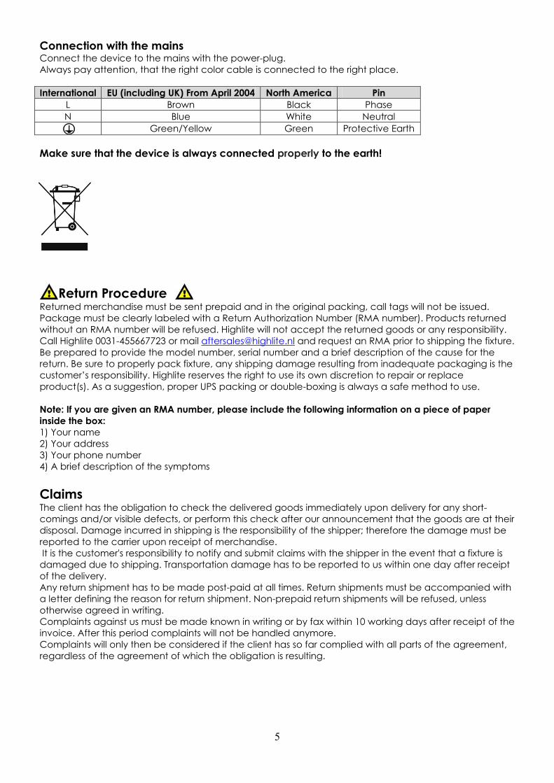
Connection with the mains Connect the device to the mains with the power-plug.
Always pay attention, that the right color cable is connected to the right place.
International EU (including UK) From April 2004 North America Pin
L Brown Black Phase
N Blue White Neutral
Green/Yellow Green Protective Earth
Make sure that the device is always connected properly to the earth!
Return Procedure Returned merchandise must be sent prepaid and in the original packing, call tags will not be issued.
Package must be clearly labeled with a Return Authorization Number (RMA number). Products returned
without an RMA number will be refused. Highlite will not accept the returned goods or any responsibility.
Call Highlite 0031-455667723 or mail [email protected] and request an RMA prior to shipping the fixture.
Be prepared to provide the model number, serial number and a brief description of the cause for the
return. Be sure to properly pack fixture, any shipping damage resulting from inadequate packaging is the
customer’s responsibility. Highlite reserves the right to use its own discretion to repair or replace
product(s). As a suggestion, proper UPS packing or double-boxing is always a safe method to use.
Note: If you are given an RMA number, please include the following information on a piece of paper
inside the box:
1) Your name
2) Your address
3) Your phone number
4) A brief description of the symptoms
Claims The client has the obligation to check the delivered goods immediately upon delivery for any short-
comings and/or visible defects, or perform this check after our announcement that the goods are at their
disposal. Damage incurred in shipping is the responsibility of the shipper; therefore the damage must be
reported to the carrier upon receipt of merchandise.
It is the customer's responsibility to notify and submit claims with the shipper in the event that a fixture is
damaged due to shipping. Transportation damage has to be reported to us within one day after receipt
of the delivery.
Any return shipment has to be made post-paid at all times. Return shipments must be accompanied with
a letter defining the reason for return shipment. Non-prepaid return shipments will be refused, unless
otherwise agreed in writing.
Complaints against us must be made known in writing or by fax within 10 working days after receipt of the
invoice. After this period complaints will not be handled anymore.
Complaints will only then be considered if the client has so far complied with all parts of the agreement,
regardless of the agreement of which the obligation is resulting.
6
Description of the device
Features The Palladium is an amplifier from DAP Audio. There are 7 different versions: P-400, P-500, P-700, P-900, P-
1200, P-1600 and P-2000.
P400 P1200
Stereo mode: Stereo mode:
• 2x 150 Watt RMS – 8 Ω • 2x 530 Watt RMS – 8 Ω
• 2x 225 Watt RMS – 4 Ω • 2x 800 Watt RMS – 4 Ω
Bridged mode: 450 Watt RMS – 8 Ω Bridged mode: 1600 Watt RMS – 8 Ω
P500 P1600
Stereo mode: Stereo mode:
• 2x 180 Watt RMS – 8 Ω • 2x 600 Watt RMS – 8 Ω
• 2x 270 Watt RMS – 4 Ω • 2x 900 Watt RMS – 4 Ω
Bridged mode: 540 Watt RMS – 8 Ω Bridged mode: 1800 Watt RMS – 8 Ω
P700 P2000
Stereo mode: Stereo mode:
• 2x 240 Watt RMS – 8 Ω • 2x 700 Watt RMS – 8 Ω
• 2x 360 Watt RMS – 4 Ω • 2x 1050 Watt RMS – 4 Ω
Bridged mode: 720 Watt RMS – 8 Ω Bridged mode: 2100 Watt RMS – 8 Ω
P900
Stereo mode:
• 2x 350 Watt RMS – 8 Ω
• 2x 525 Watt RMS – 4 Ω
Bridged mode: 1050 Watt RMS – 8 Ω
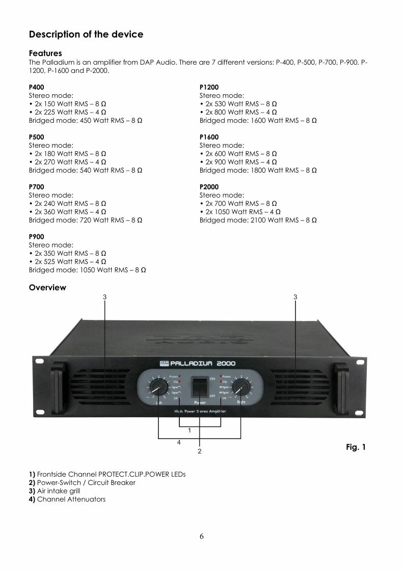
Overview
Fig. 1
1) Frontside Channel PROTECT.CLIP.POWER LEDs
2) Power-Switch / Circuit Breaker
3) Air intake grill
4) Channel Attenuators
7
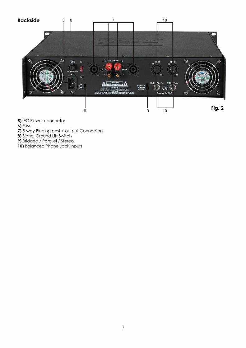
Backside
Fig. 2
5) IEC Power connector
6) Fuse
7) 5-way Binding post + output Connectors
8) Signal Ground Lift Switch
9) Bridged / Parallel / Stereo
10) Balanced Phone Jack Inputs
8
Installation Remove all packing materials. Check that all foam and plastic padding has been removed.
Secure the equipment into a 19" rack. Connect all cables.
Set Up and Operation Before plugging the unit in, always make sure that the power supply matches the product specification
voltage. Do not attempt to operate a 120V specification product on 240V power, or vice versa. Do not
supply power before all components of the system are set up and connected properly.
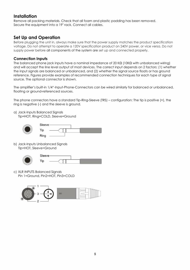
Connection Inputs The balanced phone jack inputs have a nominal impedance of 20 KΩ (10KΩ with unbalanced wiring)
and will accept the line level output of most devices. The correct input depends on 2 factors: (1) whether
the input signals are balanced or unbalanced, and (2) whether the signal source floats or has ground
reference. Figures provide examples of recommended connection techniques for each type of signal
source. The optional connector is shown.
The amplifier’s built-in 1/4“-Input-Phone-Connectors can be wired similarly for balanced or unbalanced,
floating or ground-referenced sources.
The phone connectors have a standard Tip-Ring-Sleeve (TRS) – configuration: The tip is positive (+), the
ring is negative (-) and the sleeve is ground.
a) Jack-Inputs Balanced Signals
Tip=HOT, Ring=COLD, Sleeve=Ground
b) Jack-Inputs Unbalanced Signals
Tip=HOT, Sleeve=Ground
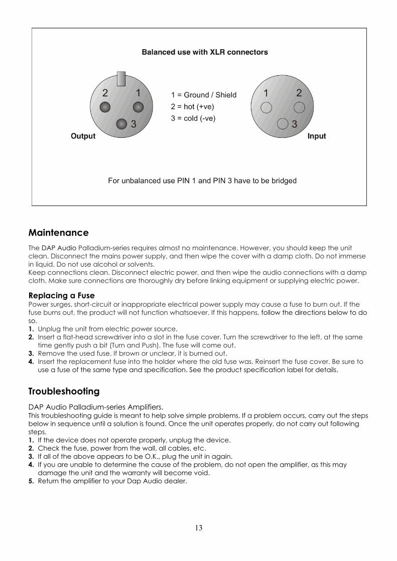
c) XLR INPUTS Balanced Signals
Pin 1=Ground, Pin2=HOT, Pin3=COLD

9
Connecting Outputs Speakers can be connected using Banana plugs, Speakon plugs or bare wire to the binding posts on the
rear panel of the amplifier. Consult the Wire-Gauge-Chart to determine suitable wire gauges for different
load impedances and cable lengths. The red binding posts are considered „hot“, connected to the
positive poles of the speakers, while the black binding-posts are Signal Ground, connected to the
negative poles of the speakers.
Never connect a „hot“ (red) Output to the Ground or to other „hot“ (red) Outputs! Always turn off the
amplifier before making connections.
Connecting Power The actual current draw, the amplifier demands from the AC mains, depends on many factors (its load,
output level or the crest factor of its program material). The power requirement is rated under typical
music conditions, with both channels driven so those peaks are just at the clipping point.
Stereo Operation For stereo (dual channel) operation, set the mode select switch to the “Stereo” position. In this mode
both channels operate independently of each other, with their input attenuates controlling their
respective levels. A signal at Channel A’s input produces an amplified signal at Channel A’s output, while
a signal at Channel B’s input produces an amplified signal at Channel B’s output.
Parallel Operation For parallel operation, set the mode select switch in the “parallel” position. In this mode, a signal applied
to Channel A's input will be amplified and appear at outputs
of both Channels A&B.

10
Bridged Mono Operation Both amplifier channels can be bridged together to make a very powerful single channel amplifier. When
the Mode switch is set to the “Bridge” position, 1 channel “pushes”, while the other “pulls” equally. Thus
effectively doubling the power. Use extreme caution when operating the amplifier in the bridged mode.
To bridge the amplifier, set the mode switch to the “Bridge” position. Apply the signal to Channel A’s
input and connect the speakers across the “hot” outputs – the red binding posts – of Channel A and B.
Channel B’s “hot” output is in phase with the input. For operation adjust only the Channel A’s input
attenuator, while Channel B’s input will not function (Channel B’s input signal has been disconnected).
Bridging Precautions
Never ground either side of the speaker cable when the amplifier is in bridged
mode; Both sides are „hot“. If an output patch panel is used, all terminals must
be isolated from each other and from the ground.
Switches and controls
Input Attenuators
Whenever possible, set attenuators fully clockwise to maintain optimum system headroom. The input
attenuator controls (one for channel A, one for channel B) located at the front panel adjust gain for their,
respective amplifier channels in all modes. See the specifications at the end of this manual for standard
voltage gain and input sensitivity information. When operating the amplifier in bridged mode, both
attenuates must be in the same position, so the speaker load will be equally shared between the
channels.
Mode-Select-Switch
The rear panel mode select switch determines whether the amplifier is in the stereo or bridged mono
mode. Do not operate the mode select switch with the amplifier on.
Ground Lift Switch
In a properly designed system (for safety and to minimize noise), the amplifier should receive its ground
from the line cord. Whenever possible, the signal source equipment should share the same AC ground as
the amplifier(s). In some cases, this may result in a ground loop. If this happens, remove the use the
ground lift switch to lift the signal ground and isolate it completely from the chassis / AC ground.
Indicators The Palladium features 4 front LED indicators per channel: Clip, Signal, Protect und Power. These LED
indicators inform the user of each channel’s operating status and warn of possible abnormal conditions.
Clip LED
A channel’s red clip LED will light dimly at the onset of clipping and increase in brilliance, as clipping
becomes more severe, staying on until the clipping ceases. If the LED’s are flashing quickly and
intermittently, the channel is just at the clip threshold, while a steady, bright glow means the amp is clip
limiting, or reducing gain to prevent severely clipped waveforms reaching the speakers.
11
Signal-LED
This green LED lights, when its channel produces an output signal of about 4 Volt RMS or more (0,1V or
more at the input, with 0dB attenuation and standard 40X voltage gain). It is useful to determine whether
the amplifier is amplifying a signal.
Protect LED
When the red LED lights, indicating that the channel has overheated, the channel’s output relay is open,
and the speaker(s) has been disconnected for any of the following reasons:
1. The unit was just powered up and is in the turn – on delay mode
2. The amplifier senses a DC voltage at its output.
Power LED
This indicator LED lights, when the amplifier has been turned on, AC power is available and the low-
voltage power supply and fan are operational.
Protection Features Every amplifier incorporates several circuits to protect themselves and the speakers under virtually any
situation. Dap Audio has attempted to make the amplifier as “foolproof” as possible by making it
impervious to short and open circuits, DC Voltage and overheating.
When a problem occurs, that causes a channel to go into a protection mode, the PROTECT for that
channel will glow. DC voltage on the output, excessive subsonic frequencies, or thermal overloads will
cause the channel’s output relay to disconnect the speaker load, until the problem is corrected or the
amplifier cools down.
The internal fan(s) will keep the amplifier operating well within its intended temperature range under all
normal conditions.
When a channel’s heat sink temperature reaches 90 ºC, which may indicate an obstructed air supply,
clogged air filter, etc, the channel will disconnect its load. Normal operation will resume automatically
once it cools to 80 ºC. During this time, the channel’s PROTECT LED will light.
Short Circuit
If an output is shorted, the protection circuit will be more sensitive, than in the normal protection situation
and will protect the channel’s output transistors from the current stress. The channel’s PROTECT LED will
light. If the short circuit remains, the channel will eventually thermally protect itself by disconnecting the
load.
DC Voltage Protection
If an amplifier channel detects DC voltage at its output, its output will immediately open to prevent
speaker damage. The channel’s PROTECT LED will light.
Subsonic Frequencies
All amplifiers have a built-in subsonic frequency protection circuit, cornered at 10Hz, for each channel.
An additional feature is a special high frequency protection technology, which enables you to
automatically disconnect speakers, when excessive high frequency energy appears at the output.
Turn-On/Turn-Off-Protection
At power up, the speakers are disconnected. The power supplies charge for about 2-3 seconds and
stabilize, and then the speakers are connected. When power is removed, speaker loop is synchronized
with the turn off signal, therefore no thumps or pops are heard.
Speaker-Protection
All amplifiers automatically protect speakers from DC voltage, subsonic signals and excessive high
frequency signal, but users should be aware of the application limits of their speakers. Be aware that the
amplifiers power does not exceed the speaker’s power capabilities.
12
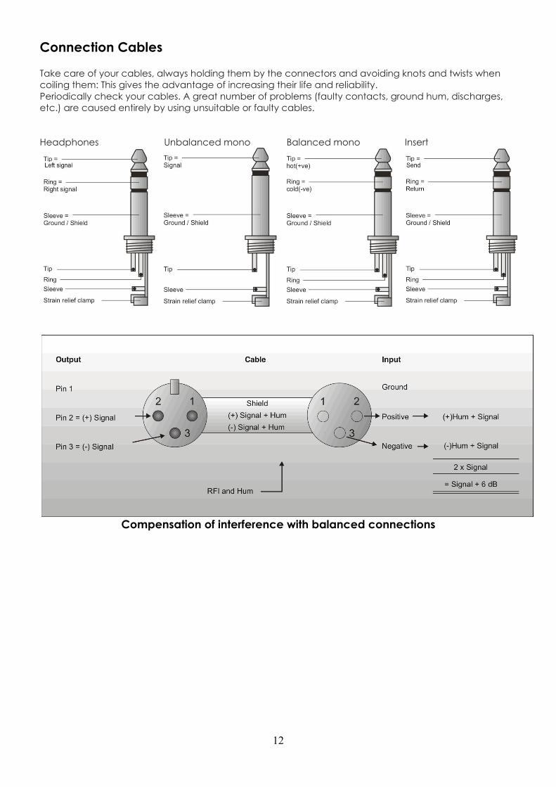
Connection Cables Take care of your cables, always holding them by the connectors and avoiding knots and twists when
coiling them: This gives the advantage of increasing their life and reliability.
Periodically check your cables. A great number of problems (faulty contacts, ground hum, discharges,
etc.) are caused entirely by using unsuitable or faulty cables.
Headphones Unbalanced mono Balanced mono Insert
Compensation of interference with balanced connections
13
Maintenance
The DAP Audio Palladium-series requires almost no maintenance. However, you should keep the unit
clean. Disconnect the mains power supply, and then wipe the cover with a damp cloth. Do not immerse
in liquid. Do not use alcohol or solvents.
Keep connections clean. Disconnect electric power, and then wipe the audio connections with a damp
cloth. Make sure connections are thoroughly dry before linking equipment or supplying electric power.
Replacing a Fuse Power surges, short-circuit or inappropriate electrical power supply may cause a fuse to burn out. If the
fuse burns out, the product will not function whatsoever. If this happens, follow the directions below to do
so.
1. Unplug the unit from electric power source.
2. Insert a flat-head screwdriver into a slot in the fuse cover. Turn the screwdriver to the left, at the same
time gently push a bit (Turn and Push). The fuse will come out.
3. Remove the used fuse. If brown or unclear, it is burned out.
4. Insert the replacement fuse into the holder where the old fuse was. Reinsert the fuse cover. Be sure to
use a fuse of the same type and specification. See the product specification label for details.
Troubleshooting
DAP Audio Palladium-series Amplifiers. This troubleshooting guide is meant to help solve simple problems. If a problem occurs, carry out the steps
below in sequence until a solution is found. Once the unit operates properly, do not carry out following
steps.
1. If the device does not operate properly, unplug the device.
2. Check the fuse, power from the wall, all cables, etc.
3. If all of the above appears to be O.K., plug the unit in again.
4. If you are unable to determine the cause of the problem, do not open the amplifier, as this may
damage the unit and the warranty will become void.
5. Return the amplifier to your Dap Audio dealer.
14
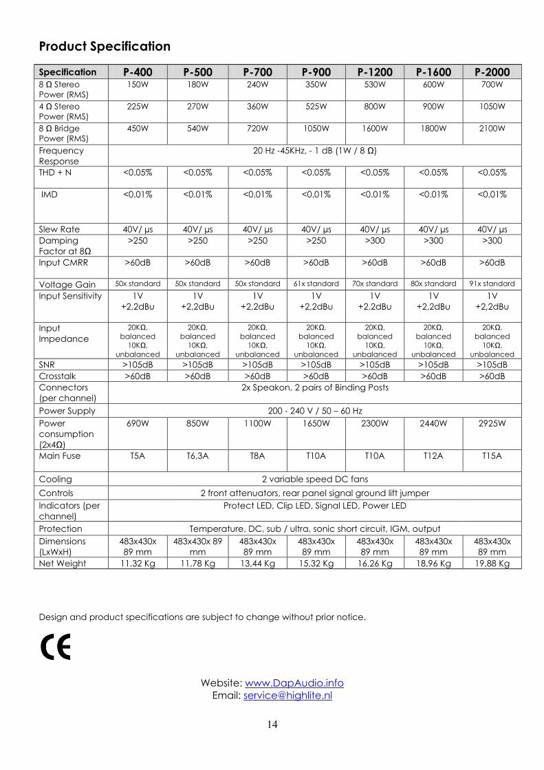
Product Specification
Specification P-400 P-500 P-700 P-900 P-1200 P-1600 P-2000 8 Ω Stereo
Power (RMS)
150W 180W 240W 350W 530W 600W 700W
4 Ω Stereo
Power (RMS)
225W 270W 360W 525W 800W 900W 1050W
8 Ω Bridge
Power (RMS)
450W 540W 720W 1050W 1600W 1800W 2100W
Frequency
Response 20 Hz -45KHz, - 1 dB (1W / 8 Ω)
THD + N <0.05% <0.05% <0.05% <0.05% <0.05% <0.05% <0.05%
IMD <0.01% <0.01% <0.01% <0.01% <0.01% <0.01% <0.01%
Slew Rate 40V/ µs 40V/ µs 40V/ µs 40V/ µs 40V/ µs 40V/ µs 40V/ µs
Damping
Factor at 8Ω
>250 >250 >250 >250 >300 >300 >300
Input CMRR >60dB >60dB >60dB >60dB >60dB >60dB >60dB
Voltage Gain 50x standard 50x standard 50x standard 61x standard 70x standard 80x standard 91x standard
Input Sensitivity 1V
+2,2dBu
1V
+2,2dBu
1V
+2,2dBu
1V
+2,2dBu
1V
+2,2dBu
1V
+2,2dBu
1V
+2,2dBu
Input
Impedance
20KΩ,
balanced
10KΩ,
unbalanced
20KΩ,
balanced
10KΩ,
unbalanced
20KΩ,
balanced
10KΩ,
unbalanced
20KΩ,
balanced
10KΩ,
unbalanced
20KΩ,
balanced
10KΩ,
unbalanced
20KΩ,
balanced
10KΩ,
unbalanced
20KΩ,
balanced
10KΩ,
unbalanced
SNR >105dB >105dB >105dB >105dB >105dB >105dB >105dB
Crosstalk >60dB >60dB >60dB >60dB >60dB >60dB >60dB
Connectors
(per channel) 2x Speakon, 2 pairs of Binding Posts
Power Supply 200 - 240 V / 50 – 60 Hz Power
consumption
(2x4Ω)
690W 850W 1100W 1650W 2300W 2440W 2925W
Main Fuse T5A T6,3A T8A T10A T10A T12A T15A
Cooling 2 variable speed DC fans Controls 2 front attenuators, rear panel signal ground lift jumper Indicators (per
channel) Protect LED, Clip LED, Signal LED, Power LED
Protection Temperature, DC, sub / ultra, sonic short circuit, IGM, output Dimensions
(LxWxH)
483x430x
89 mm
483x430x 89
mm
483x430x
89 mm
483x430x
89 mm
483x430x
89 mm
483x430x
89 mm
483x430x
89 mm
Net Weight 11,32 Kg 11,78 Kg 13,44 Kg 15,32 Kg 16,26 Kg 18,96 Kg 19,88 Kg
Design and product specifications are subject to change without prior notice.
Website: www.DapAudio.info
Email: [email protected]
15
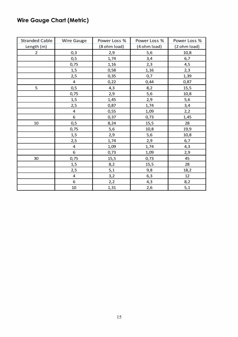
Wire Gauge Chart (Metric)
Stranded Cable Wire Gauge Power Loss % Power Loss % Power Loss %
Length (m) (8 ohm load) (4 ohm load) (2 ohm load)
2 0,3 2,9 5,6 10,8
0,5 1,74 3,4 6,7
0,75 1,16 2,3 4,5
1,5 0,58 1,16 2,3
2,5 0,35 0,7 1,39
4 0,22 0,44 0,87
5 0,5 4,3 8,2 15,5
0,75 2,9 5,6 10,8
1,5 1,45 2,9 5,6
2,5 0,87 1,74 3,4
4 0,55 1,09 2,2
6 0,37 0,73 1,45
10 0,5 8,24 15,5 28
0,75 5,6 10,8 19,9
1,5 2,9 5,6 10,8
2,5 1,74 2,9 6,7
4 1,09 1,74 4,3
6 0,73 1,09 2,9
30 0,75 15,5 0,73 45
1,5 8,2 15,5 28
2,5 5,1 9,8 18,2
4 3,2 6,3 12
6 2,2 4,3 8,2
10 1,31 2,6 5,1

16
Wire Gauge Chart (AWG: American Wire Gauge)
Stranded Cable Wire Gauge Power Loss % Power Loss % Power Loss %
Length(ft) (AWG) (8 ohm load) (4 ohm load) (2 ohm load)
5 18 0.81 1.61 3.2
16 0.51 1.02 2
14 0.32 0.64 1.28
12 0.2 0.4 0.8
10 0.128 0.25 0.51
10 18 1.61 3.2 6.2
16 1.02 2 4
14 0.64 1.28 2.5
12 0.4 0.8 1.6
10 0.25 0.51 1.01
40 18 6.2 11.9 22
16 4 7.7 14.6
14 2.5 5 9.6
12 1.6 3.2 6.2
10 1.01 2 4
8 0.6 1.2 2.4
80 18 11.9 22 37
16 7.7 14.6 26
14 5 9.6 17.8
12 3.2 6.2 11.8
10 2 4 7.7