
Page 1HMI Team Meeting – January 26-27, 2005 HMI Investigation Overview Philip Scherrer...
21
Page 1 HMI Team Meeting – January 26-27, 2005 HMI Investigation Overview Philip Scherrer [email protected] 650-723-1504
-
date post
21-Dec-2015 -
Category
Documents
-
view
214 -
download
1
Transcript of Page 1HMI Team Meeting – January 26-27, 2005 HMI Investigation Overview Philip Scherrer...
Page 1 HMI Team Meeting – January 26-27, 2005
HMI Investigation Overview
Philip Scherrer
650-723-1504
Page 2 HMI Team Meeting – January 26-27, 2005
SDO - Solar Dynamics Observatory
HOP
HEB
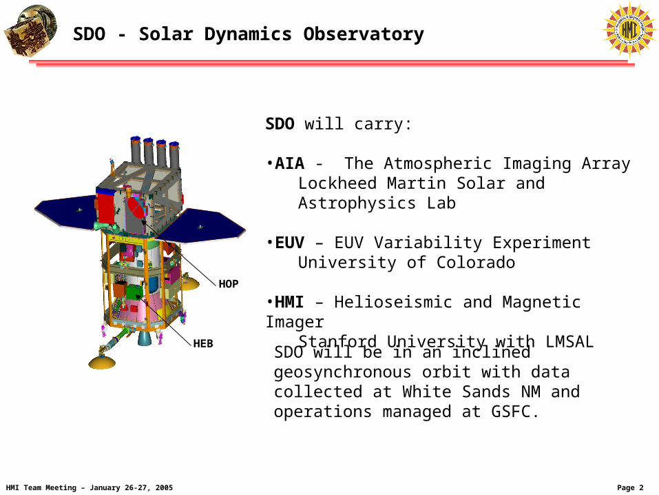
SDO will carry:
•AIA - The Atmospheric Imaging ArrayLockheed Martin Solar and Astrophysics Lab
•EUV – EUV Variability ExperimentUniversity of Colorado
•HMI – Helioseismic and Magnetic ImagerStanford University with LMSAL
SDO will be in an inclined geosynchronous orbit with data collected at White Sands NM and operations managed at GSFC.

Page 3 HMI Team Meeting – January 26-27, 2005
Goals for January 2005 Team Meeting
We are now just after the HMI Critical Design Review.
The flight instrument is being built and will be ready for optical testing this summer.
It will be delivered to NASA for integration onto SDO in November of next year.
Proposal was about three years ago and launch about three years away.
The data processing center design is near completion.
We are near the point where we will need to begin the process of incorporating analysis software.
The primary goals for this meeting are to:
• Update the specifications for standard data products
• Confirm Co-I plans for analysis software development
• Encourage coordination in development of science analysis techniques
• Update the Science Team on the project status
• Clarify priorities for early science goals
Page 4 HMI Team Meeting – January 26-27, 2005
HMI Institutional Roles
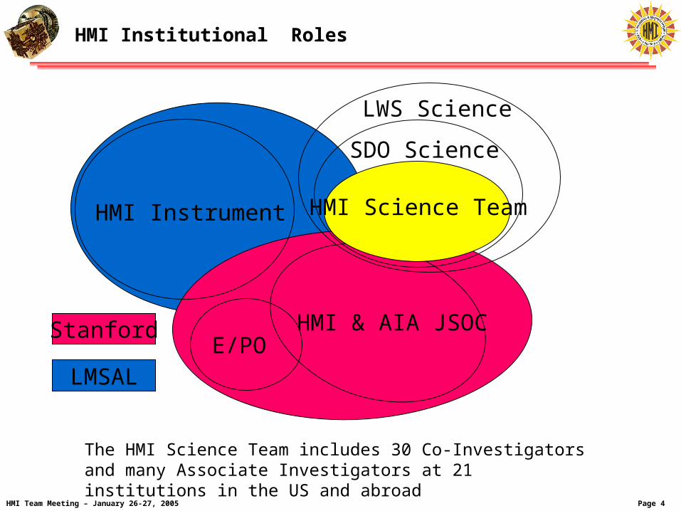
HMI Instrument
HMI & AIA JSOC
SDO Science
LWS Science
E/POStanford
LMSAL
The HMI Science Team includes 30 Co-Investigators and many Associate Investigators at 21 institutions in the US and abroad
HMI Science Team

Page 5 HMI Team Meeting – January 26-27, 2005
HMI Science Investigator Team - 1
HMI Science Team
Name Role Institution Phase B,C,D Phase-E
HMI Lead Institutions
Philip H. Scherrer PI Stanford University HMI Investigation Solar Science
John G. Beck A-I Stanford University E/PO Science Liaison Surface Flows
Richard S. Bogart Co-I Stanford University Data Pipeline and Access Near Surface Flows
Rock I. Bush Co-I Stanford University Program Manager Irradiance and Shape
Thomas L. Duvall, Jr. Co-I NASA Goddard Space Flight Center Time-Distance Code Helioseismology
Alexander G. Kosovichev Co-I Stanford University Inversion Code Helioseismology
Yang Liu A-I Stanford University Vector Field Observable Code Active Region Fields
Jesper Schou Co-I Stanford University Instrument Scientist Helioseismology
Xue Pu Zhao Co-I Stanford University Coronal Code Coronal Field Models
Alan M. Title Co-I LMSAL HMI Instrument Solar Science
Thomas Berger A-I LMSAL * Vector Field Calibration Active Region Science
Thomas R. Metcalf Co-I LMSAL * Vector Field Calibration Active Region Science
Carolus J. Schrijver Co-I LMSAL * Magnetic Field Assimilation Models Active Region Science
Theodore D. Tarbell Co-I LMSAL HMI Calibration Active Region Science
Bruce W. Lites A-I High Altitude Observatory Vector Field Inversions Active Region Science
Steven Tomczyk Co-I High Altitude Observatory Vector Field Inversions Active Region Science
* Phase D only
Page 6 HMI Team Meeting – January 26-27, 2005
HMI Science Investigator Team - 2
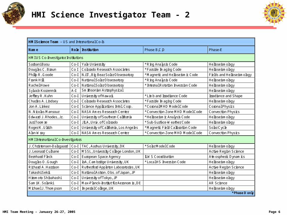
HMI Science Team – US and International Co-Is
Name Role Institution Phase B,C,D Phase-E
HMI US Co-Investigator Institutions
Sarbani Basu Co-I Yale University * Ring Analysis Code Helioseismology
Douglas C. Braun Co I Colorado Research Associates * Farside Imaging Code Helioseismology
Philip R. Goode Co-I NJIT, Big Bear Solar Observatory * Magnetic and Helioseismic Code Fields and Helioseismology
Frank Hill Co-I National Solar Observatory * Ring Analysis Code Helioseismology
Rachel Howe Co-I National Solar Observatory * Internal Rotation Inversion Code Helioseismology
Sylvain Korzennik A-I Smithsonian Astrophysical Observatory
Helioseismology
Jeffrey R. Kuhn Co-I University of Hawaii * Limb and Irradiance Code Irradiance and Shape
Charles A. Lindsey Co-I Colorado Research Associates * Farside Imaging Code Helioseismology
Jon A. Linker Co-I Science Applications Intnl. Corp. * Coronal MHD Model Code Coronal Physics
N. Nicolas Mansour Co-I NASA Ames Research Center * Convection Zone MHD Model Code Convection Physics
Edward J. Rhodes, Jr. Co-I University of Southern California * Helioseismic Analysis Code Helioseismology
Juri Toomre Co-I JILA, Univ. of Colorado * Sub-Surface-Weather Code Helioseismology
Roger K. Ulrich Co-I University of California, Los Angeles * Magnetic Field Calibration Code Solar Cycle
Alan Wray Co-I NASA Ames Research Center * Convection Zone MHD Model Code Convection Physics
HMI International Co-Investigators
J. Christensen-Dalsgaard Co-I TAC, Aarhus University, DK * Solar Model Code Helioseismology
J. Leonard Culhane Co-I MSSL, University College London, UK Active Region Science
Bernhard Fleck Co-I European Space Agency ILWS Coordination Atmospheric Dynamics
Douglas O. Gough Co-I IoA, Cambridge University, UK * Local HS Inversion Code Helioseismology
Richard A. Harrison Co-I Rutherford Appleton Laboratories, UK Active Region Science
Takashi Sekii Co-I National Astron. Obs. of Japan, JP Helioseismology
Hiromoto Shibahashi Co-I University of Tokyo, JP Helioseismology
Sami K. Solanki Co-I Max-Planck-Institut für Aeronomie, DE AR Science
Michael J. Thompson Co-I Imperial College, UK Helioseismology * Phase D only
Page 7 HMI Team Meeting – January 26-27, 2005
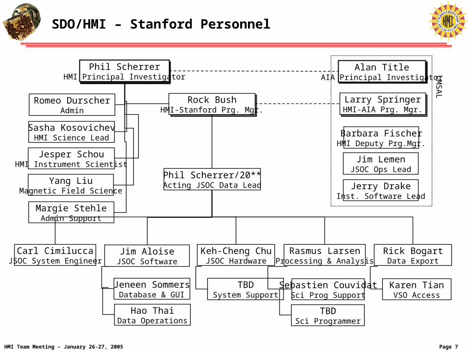
SDO/HMI – Stanford Personnel
Phil ScherrerHMI Principal Investigator
Jesper SchouHMI Instrument Scientist
Rock BushHMI-Stanford Prg. Mgr.
Romeo DurscherAdmin
Sasha KosovichevHMI Science Lead
Phil Scherrer/20**Acting JSOC Data Lead
Alan TitleAIA Principal Investigator
Larry SpringerHMI-AIA Prg. Mgr.
Jerry DrakeInst. Software Lead
LM
SA
L
Barbara FischerHMI Deputy Prg.Mgr.
Jim LemenJSOC Ops Lead
Yang LiuMagnetic Field Science
Margie StehleAdmin Support
Carl CimiluccaJSOC System Engineer
Keh-Cheng ChuJSOC Hardware
TBDSystem Support
Jim AloiseJSOC Software
Jeneen SommersDatabase & GUI
Hao ThaiData Operations
Rasmus LarsenProcessing & Analysis
Sebastien CouvidatSci Prog Support
Rick BogartData Export
Karen TianVSO Access
TBDSci Programmer
Page 8 HMI Team Meeting – January 26-27, 2005
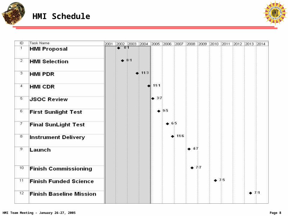
HMI Schedule
Page 9 HMI Team Meeting – January 26-27, 2005
The primary goal of the Helioseismic and Magnetic Imager (HMI) investigation is to study the origin of solar variability and to characterize and understand the Sun’s interior and the various components of magnetic activity.
HMI makes measurements of the motion of the solar photosphere to study solar oscillations in order to determine the interior sources and mechanisms of solar variability
It also makes measurements of the photospheric magnetic field in order to study how the physical processes inside the Sun are related to surface magnetic field and to enable estimates of the low and far coronal magnetic field for studies of variability in the extended solar atmosphere.
Investigation Overview
Page 10 HMI Team Meeting – January 26-27, 2005
HMI science objectives are grouped into five broad categories:
• Convection-zone dynamics and the solar dynamo;How does the solar cycle work?
• Origin and evolution of sunspots, active regions and complexes of activity;What drives the evolution of spots and active regions?
• Sources and drivers of solar activity and disturbances;How and why is magnetic complexity expressed as activity?
• Links between the internal processes and dynamics of the corona and heliosphere;
What are the large scale links between the important domains?
• Precursors of solar disturbances for space-weather forecasts.What are the prospects for predictions?
These objectives are divided into 18 sub-objectives each of which needs data from multiple HMI data products.
Progress requires a science team with experience in multiple disciplines.
HMI Science Objectives – Top Level
Page 11 HMI Team Meeting – January 26-27, 2005
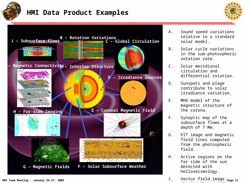
A. Sound speed variations relative to a standard solar model.
B. Solar cycle variations in the sub-photospheric rotation rate.
C. Solar meridional circulation and differential rotation.
D. Sunspots and plage contribute to solar irradiance variation.
E. MHD model of the magnetic structure of the corona.
F. Synoptic map of the subsurface flows at a depth of 7 Mm.
G. EIT image and magnetic field lines computed from the photospheric field.
H. Active regions on the far side of the sun detected with helioseismology.
I. Vector field image showing the magnetic connectivity in sunspots.
J. Sound speed variations and flows in an emerging active region.
B – Rotation VariationsC – Global Circulation
D – Irradiance Sources
H – Far-side Imaging
F – Solar Subsurface Weather
E – Coronal Magnetic Field
I – Magnetic Connectivity
J – Subsurface flows
G – Magnetic Fields
A – Interior Structure
HMI Data Product Examples
Page 12 HMI Team Meeting – January 26-27, 2005 Version 1.0
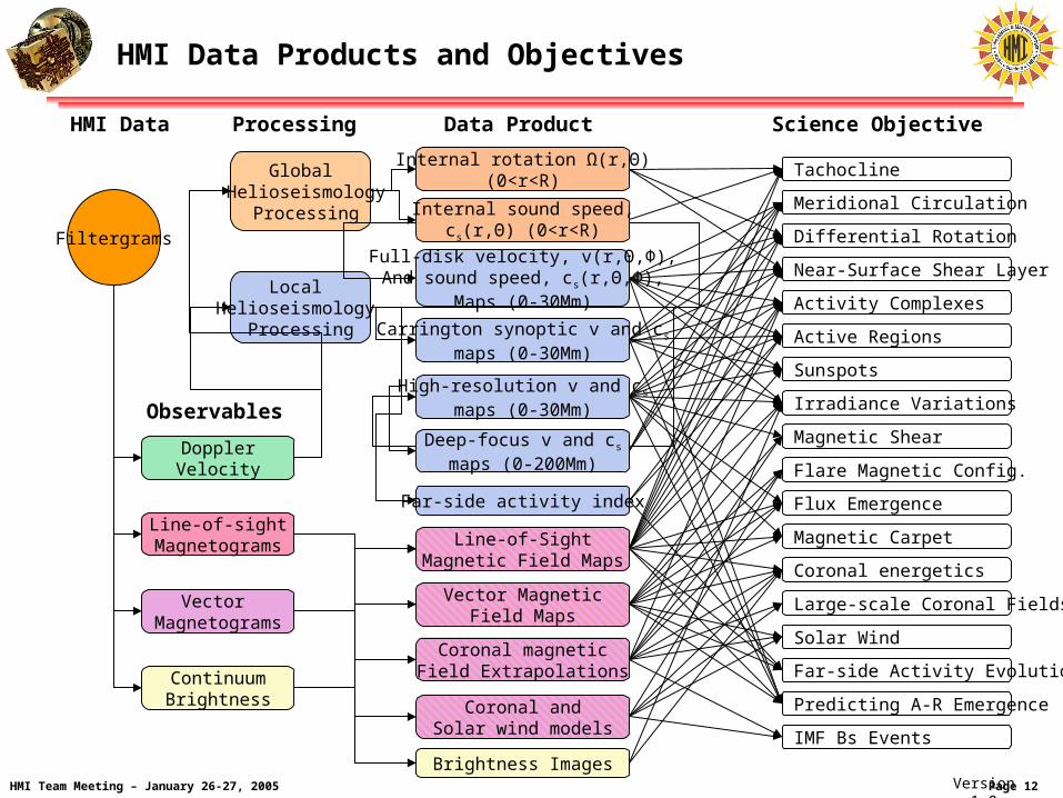
Global Helioseismology
Processing
Local Helioseismology
Processing
Filtergrams
Line-of-sightMagnetograms
Vector Magnetograms
DopplerVelocity
ContinuumBrightness
Brightness Images
Line-of-SightMagnetic Field Maps
Coronal magneticField Extrapolations
Coronal andSolar wind models
Far-side activity index
Deep-focus v and cs
maps (0-200Mm)
High-resolution v and cs
maps (0-30Mm)
Carrington synoptic v and cs
maps (0-30Mm)
Full-disk velocity, v(r,Θ,Φ),And sound speed, cs(r,Θ,Φ),
Maps (0-30Mm)
Internal sound speed,cs(r,Θ) (0<r<R)
Internal rotation Ω(r,Θ)(0<r<R)
Vector MagneticField Maps
Tachocline
Differential Rotation
Meridional Circulation
Near-Surface Shear Layer
Activity Complexes
Active Regions
Sunspots
Irradiance Variations
Magnetic Shear
Flare Magnetic Config.
Flux Emergence
Magnetic Carpet
Coronal energetics
Large-scale Coronal Fields
Solar Wind
Far-side Activity Evolution
Predicting A-R Emergence
IMF Bs Events
Science ObjectiveData ProductProcessing
Observables
HMI Data
HMI Data Products and Objectives
Page 13 HMI Team Meeting – January 26-27, 2005
HMI-AIA Joint Science Operations Center
• HMI and AIA SOCs have been merged to form a JSOC
• Components of the JSOC will be at both Stanford and Lockheed-Martin Solar and Astrophysics Lab (LMSAL)
– JSOC-Ops for both HMI and AIA at LMSAL
– Data capture, pipeline processing, online archive, tape archive, export functions at Stanford.
– HMI Higher level processing at Stanford
– AIA Higher level processing at LMSAL
– High-speed network connection between the two sites
• The JSOC will be discussed in more detail as part of both the SDO CDR and the SDO ground system CDR next year
Page 14 HMI Team Meeting – January 26-27, 2005
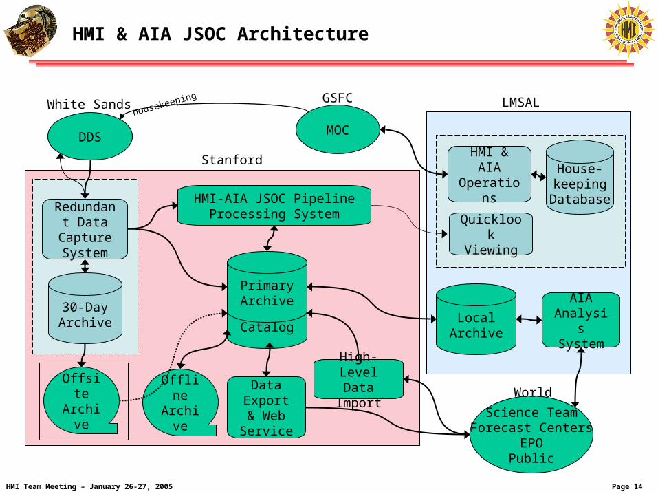
HMI & AIA JSOC Architecture
Science TeamForecast Centers
EPOPublic
Catalog
Primary Archive
HMI & AIAOperations
House-keeping
Database
MOCDDS
Redundant Data
Capture System
30-DayArchive
OffsiteArchiv
e
OfflineArchiv
e
HMI-AIA JSOC Pipeline Processing System
DataExport& WebService
Stanford
LMSAL
High-LevelData Import
AIA AnalysisSystem
Local Archive
QuicklookViewing
housekeeping GSFCWhite Sands
World
Page 15 HMI Team Meeting – January 26-27, 2005
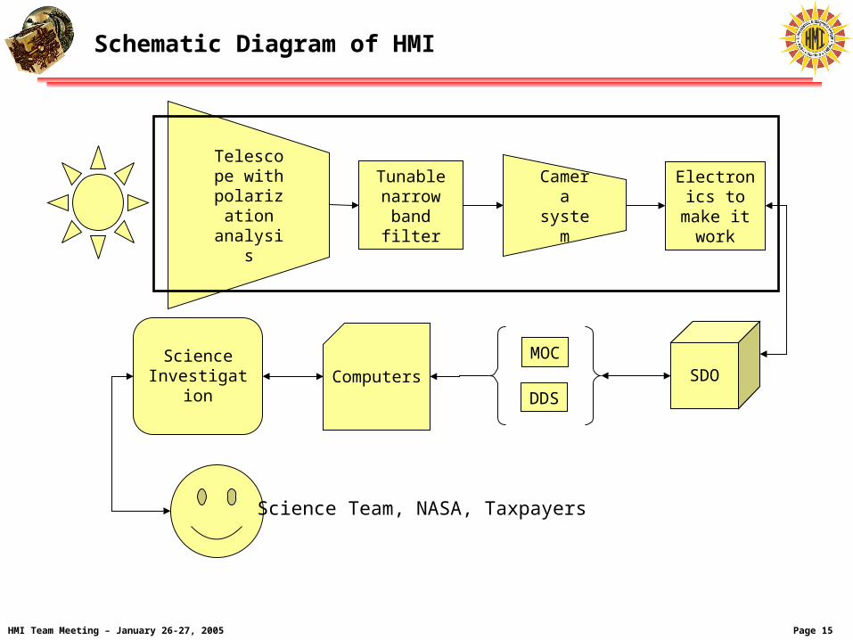
Schematic Diagram of HMI
Telescope with
polarization
analysis
Tunable narrow
band filter
Camera
system
SDOMOC
DDSComputers
Electronics to make it
work
Science Investigation
Science Team, NASA, Taxpayers

Page 16 HMI Team Meeting – January 26-27, 2005
6169 6172 6175 6178
Measure Here
HMI consists of a telescope, tunable filter, camera, and necessary electronics.
HMI repeatedly images the Sun in six polarizations at five wavelengths across a spectral line.
The position of the line tells us the velocity while the shape changes of the line in different polarizations tell us the magnetic field direction and strength in the part of the Sun’s surface seen by each pixel.
Long gap-free sequences of velocity images are needed to enable the techniques of helioseismology.
HMI – How It Works
Page 17 HMI Team Meeting – January 26-27, 2005
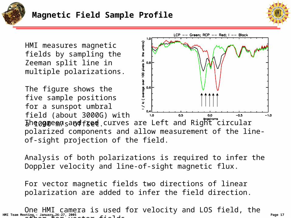
The green and red curves are Left and Right circular polarized components and allow measurement of the line-of-sight projection of the field.
Analysis of both polarizations is required to infer the Doppler velocity and line-of-sight magnetic flux.
For vector magnetic fields two directions of linear polarization are added to infer the field direction.
One HMI camera is used for velocity and LOS field, the other for vector fields.
Magnetic Field Sample Profile
HMI measures magnetic fields by sampling the Zeeman split line in multiple polarizations.
The figure shows the five sample positions for a sunspot umbral field (about 3000G) with a 1000 m/s offset.

Page 18 HMI Team Meeting – January 26-27, 2005
Basic Requirements Sources
• SDO Level 1 Requirements
• SDO Mission Requirements Document (MRD)
– Summary of spacecraft and instrument driving requirements
• HMI Instrument Functional Specification
– Top level instrument requirements – part of the HMI contract statement of work
• HMI Instrument Performance Document (IPD)
– Detailed HMI science drivers and flowdown to subsystem requirements
• HMI Performance Assurance and Implementation Plan (PAIP)
– HMI implementation of the SDO Mission Assurance Requirements
• HMI to Spacecraft Interface Control Documents (HMI-S/C ICD)
• Ground System Interface Control Documents
Page 19 HMI Team Meeting – January 26-27, 2005
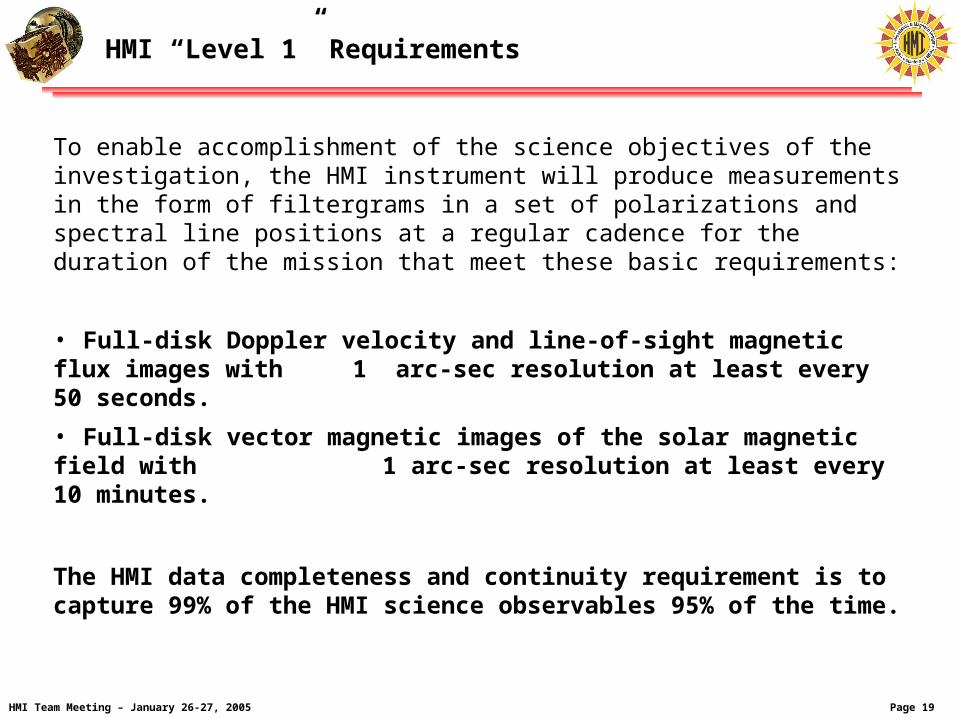
HMI “Level 1” Requirements
To enable accomplishment of the science objectives of the investigation, the HMI instrument will produce measurements in the form of filtergrams in a set of polarizations and spectral line positions at a regular cadence for the duration of the mission that meet these basic requirements:
• Full-disk Doppler velocity and line-of-sight magnetic flux images with 1 arc-sec resolution at least every 50 seconds.
• Full-disk vector magnetic images of the solar magnetic field with 1 arc-sec resolution at least every 10 minutes.
The HMI data completeness and continuity requirement is to capture 99% of the HMI science observables 95% of the time.
Page 20 HMI Team Meeting – January 26-27, 2005
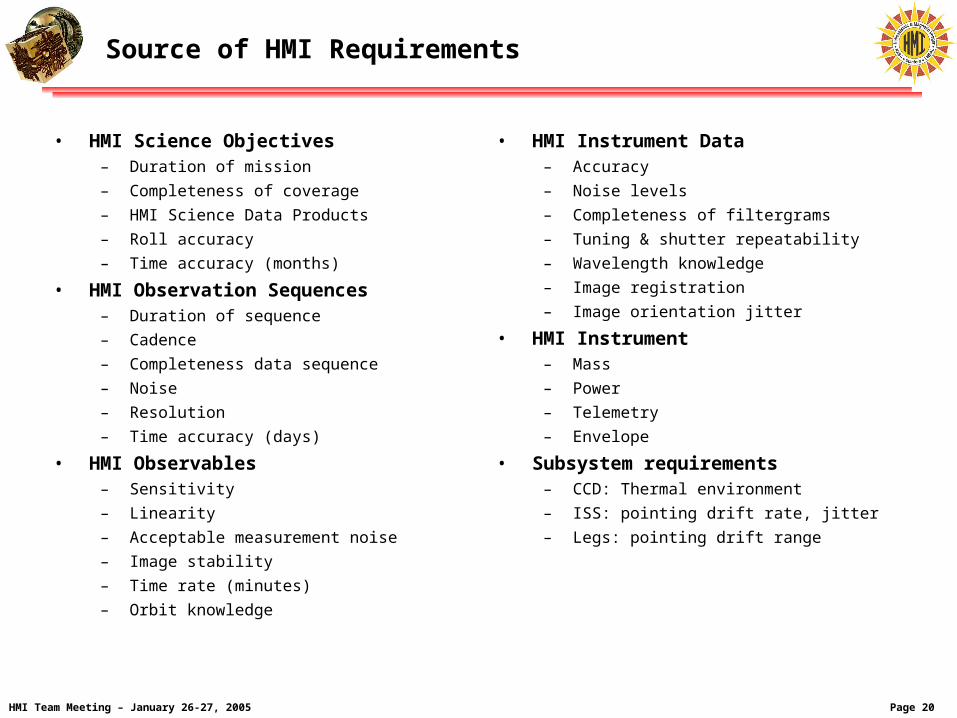
Source of HMI Requirements
• HMI Science Objectives– Duration of mission
– Completeness of coverage
– HMI Science Data Products
– Roll accuracy
– Time accuracy (months)
• HMI Observation Sequences – Duration of sequence
– Cadence
– Completeness data sequence
– Noise
– Resolution
– Time accuracy (days)
• HMI Observables– Sensitivity
– Linearity
– Acceptable measurement noise
– Image stability
– Time rate (minutes)
– Orbit knowledge
• HMI Instrument Data– Accuracy
– Noise levels
– Completeness of filtergrams
– Tuning & shutter repeatability
– Wavelength knowledge
– Image registration
– Image orientation jitter
• HMI Instrument– Mass
– Power
– Telemetry
– Envelope
• Subsystem requirements– CCD: Thermal environment
– ISS: pointing drift rate, jitter
– Legs: pointing drift range

Page 21 HMI Team Meeting – January 26-27, 2005
HMI Performance Requirements Summary
Parameter Requirement Central wavelength 6173.3 Å ± 0.1 Å (Fe I line) Filter bandwidth 76 mÅ ± 10 mÅ fwhm Filter tuning range 680 mÅ ± 68 mÅ Central wavelength drift < 10 mÅ during any 1 hour period Field of view > 2000 arc-seconds Angular resolution better than 1.5 arc-seconds Focus adjustment range ± 4 depths of focus Pointing jitter reduction factor > 40db with servo bandwidth > 30 Hz Image stabilization offset range > ± 14 arc-seconds in pitch and yaw Pointing adjustment range > ± 200 arc-seconds in pitch and yaw Pointing adjustment step size < 2 arc-seconds in pitch and yaw Dopplergram cadence < 50 seconds Image cadence for each camera < 4 seconds Full image readout rate < 3.2 seconds Exposure knowledge < 5 microseconds Timing accuracy < 0.1 seconds of ground reference time Detector format > 4000 x 4000 pixels Detector resolution 0.50 ± 0.01 arc-second / pixel Science telemetry compression To fit without loss in allocated telemetry Eclipse recovery < 60 minutes after eclipse end Instrument design lifetime 5 years at geosynchronous orbit