
Page | 1 Technical Specification OFFICE and SANITARY ... · Technical Specification OFFICE and...
18
Technical Specification OFFICE and SANITARY Modular Units CONTENTS 1. General Information 1.1. Dimensions (mm) & weights (kg) 1.2. Abbreviations 1.3. Standard configuration 1.4. Insulation 1.5. Load bearing capacity 1.6. Basic principles of the static calculations 1.7. Sound insulation 2. Cabin Design 2.1. Floor 2.2. Roof 2.3. Corner posts 2.4. Wall panels 2.5. Partition walls 2.6. Doors 2.7. Windows 3. Electrical installation 3.1. Technical data 3.2. Heating and air conditioning 4. Miscellaneous 4.1. Transport height 4.2. Construction, Assembly, Statics, Servicing 4.3. Handling 4.4. Certification 4.5. Paint 5. Equipment options for sanitary cabins and fixtures in office cabins 5.1. . Water installation Page | 1
Transcript of Page | 1 Technical Specification OFFICE and SANITARY ... · Technical Specification OFFICE and...

Technical Specification OFFICE and SANITARY Modular Units
CONTENTS
1. General Information 1.1. Dimensions (mm) & weights (kg) 1.2. Abbreviations 1.3. Standard configuration 1.4. Insulation 1.5. Load bearing capacity 1.6. Basic principles of the static calculations 1.7. Sound insulation
2. Cabin Design 2.1. Floor 2.2. Roof 2.3. Corner posts 2.4. Wall panels 2.5. Partition walls 2.6. Doors 2.7. Windows
3. Electrical installation 3.1. Technical data 3.2. Heating and air conditioning
4. Miscellaneous 4.1. Transport height 4.2. Construction, Assembly, Statics, Servicing 4.3. Handling 4.4. Certification 4.5. Paint
5. Equipment options for sanitary cabins and fixtures in office cabins 5.1. . Water installation
Page | 1

Page | 2
5.2.Appendix 5.2.1. Arrangement options for
5.2.1.1. 10’ 16’ 20’ modules; max external height 2.80m 5.2.1.2. 10’ 16’ 20’ modules; max external height 2.96m
5.2.1.3. 24’ 30’ modules; max external height 2.80m 5.2.1.4. 24’ 30’ modules; max external height 2.96m
5.2.2. Standard foundation plan for
5.2.2.1. 10’ 16’ 20’ cabin 5.2.2.2. 24’ 30’ cabin
5.2.3. Handling instructions for 5.2.4. 10’ 16’ 20’ Transpack cabins 5.2.5. 30’ Transpack cabin

Page | 3
1. General Information The information below relates to the finish, design and equipment of new office and sanitary cabins
Our cabins match the ISO-norm dimensions; the consist of a robust frame construction and have interchangeable wall panels
In the text below the CMU standard office cabin is marked ‘1’
the standard sanitary unit is marked ‘2’
Design options NOT marked with ‘1’ or ‘2’ will be supplied only if specified in the written agreement
1.1. Dimensions (mm) and Weight (kg)
10’ L2989x W2435xH 2591 L2795xW2240xH2340 BM1150 BU1200 SU1450 10’ H2800 H2540 BM1350 BU1200 SU1550 10’ H2960 H2700
16’ L4885xW2435xH2591 L4690xW2240xH2340 BM1600 BU1550 16’ H2800 H2540 BM1750 BU1600 16’ H2960 H2700
20’ L6055XW2435xH2591 L5860xW2240xH2340 BM1950 BU1750 SU2450 20’ H2800 H2540 BM2000 BU1800 SU2550 20’ H2960 H2700
24’ L7335xW2435xH2591 L7140xW2240xH2340 BM2300 BU2050 24’ H2800 H2540 BM2400 BU2150 24’ H2960 H2700
30’ L9120xW2435xH2591 L8925xW2240xH2340 BM2550 BU2450 30’ H2800 H2540 BM2800 BU2500
Note : the dimensions and weights are valid for standard configurations (see 1.3) and can vary depending on configuration and equipment
Type External Internal Weight (approx)
1.2. Abbreviations
The abbreviations below are used in this document
Office cabin with mineral wool insulation BM Office cabin with PU foam insulation BU
Sanitary cabin with mineral wood insulation SA Sanitary cabin with PU foam insulation SU
Mineral wool MW Polyurethane foam PU
Internal height RIH External cabin height CAH
Transpack (BM/BU in a package) TP Toughened safety glass ESG
1.3. Standard configuration attached as a separate document
Page | 4

1.4. Insulation
Component InsulationType Thickness u-VALUE (w/M2K)* Roof MW ‘1’ & ‘2’ 100 0.359 Roof MW 140 0.233 Roof PU 100 0.198 Roof PU 140 0.145
Wall element MW ‘1’ 60 0.574 Wall element MW 100 0.348 Wall element PU ‘2’ 60 0.380 Wall element PU 110 0.210
Floor MW ‘1’ & ‘2’ 60 0.548
Floor MW 100 0.364 Floor PU 100 0.196
Window standard ‘1’ & ‘2’ 4/16/4mm 2.90 Window standard gas 4/16/4mm 1.10
External door polystyrene 40mm 1.40
*u-Values apply to the stated insulation thickness in the space between the timber frames in a half- timbered construction (within the panel)
Further insulation options upon request
1.5. Load-bearing capacity
FLOOR LOAD ground floor : max. load capacity 2.0kN/m2 (200kg/ m2)
top floors : max. load capacity 1.5kN/m2 (150kg/ m2)
ground floor : max.load capacity 4.0kN/m2 (400kg/m2)
SNOW LOAD max. load capacity 1.5kN/m2 (150kg/ m2) (equates to a typical snow load on the ground of sk1. max. load capacity 1.25kN/m2
(125kg/ m2) according to EN1991-1-3 with the national application document B1991-1-3)
Page | 5

Page | 6
1.5. Load-bearing capacity…
WIND LOAD 90km/h (25m/s) - Terrain Category III When wind speeds are higher than 90km/h (25m/s), additional safety measures such as anchoring or screwing need to be taken
Such measurements are to be calculated by approved specialists taking into consideration local standards and conditions
All calculations were undertaken according the to the European ENV standards
Higher load capacity upon request
1.6. Basic principles of the static calculations
exposed side EN1900 (Eurocode 0 : basic principles)
EN1991-1-1-3 (Eurocode 1 : snow) EN1991-1-1-4 (Eurocode 1 : wind)
non-exposed side EN1993-1-1 (Eurocode 3 : steel)
EN1995-1-1 (Eurocode 5 : wood)
Sound insulation 33 – 44dB
2. Cabin design 2.1. Floor
frame construction : cold-rolled, welded steel profiles; thickness 2.50/3.00 mm 4 x corner casts, welded 2 x forklift pockets on the long side (apart from 30’ type)
forklift pockets : interior clearance of 352 x 85mm forklift pockets : distance in centre of 2050mm ‘1’ & ‘2’
optional : 950mm, 1650mm or without forklift pockets
steel cross members with omega profiles (2.50mm thickness) optional : double number of floor cross members
double number of floor cross members with under-padding

2. Cabin design 2.1. Floor…
Page | 7
insulation : type
MW ‘1’ & ‘2’
fire behaviour A1 (non-flammable) according to EN13501-1 Rockwool
PU flame behaviour B2 according to DIN4102-1
insulation thickness 60mm‘1’ & ‘2’/100mm
subfloor 0.6mm thick galvanised steel sheets (subject to differing steel finish)
floor floor plates : chipboard ‘1’ thickness 22mm E1 in accordance with EN312:2003 fire behaviour D-s2 & d0 respectively & Dft-s1 in accordance with EN13501-1
plywood board ‘1’ thickness 21mm E1 in accordance with EN717-2 and fire behaviour D-s2, d0 respectively Dfls1 in accordance with EC13501-1
cement-bound chipboard ‘2’ thickness 20mm E1 in accordance with EN717-1 fire behaviour A2-s1, d0 in accordance with EN13501-1
floor cover : vinyl floor cover ‘1’ thickness 1.5mm fire behaviour Bfl-s1 in accordance with EN13501-1 European classification EN685: stress class 23-31 welded seams
vinyl floor cover thickness 2.0mm fire behaviour Bfl-s1 in accordance with EN13501-1 European classification EN685: stress class 34-43 welded seams
pvc knob floor ‘2’ thickness 1.1 + .02mm fire behaviour Bfl-s1 in accordance with EN13501-1 European classification EN685: stress class 22 welded in sanitary areas or pulled up on request aluminium checker plate

2.2. Roof frame construction : cold-rolled, welded steel profiles; thickness 3mm
4 corner casts: welded roof cross members: made of wood
cover galvanised steel plate with double rabbet: thickness .06mm
insulation type MW ‘1’/’2’
fire behaviour A1 (non-flammable) in accordance with EN13501-1
PU flame behaviour B2 in accordance with DIN4201-1
insulation thickness 100mm ’1’/’2’ / 140mm
ceiling sheeting coated chipboard ‘1’
10mm thick, white E1 in accordance with EN312 flame behaviour D-s2, d0 in accordance with EN13501-1
plasterboard with coated steel plate ‘2’
10mm thick, white (similar to RAL9010) flame behaviour A2-s, d0 in accordance with EN13501-1
CEE connectors externally sunk into short-sided Cabin frame
2.3. Corner posts cold-rolled, welded steel profiles; thickness 4mm
steel quality S275JR+AR (St44) screwed to roof & doorframe
Page | 8
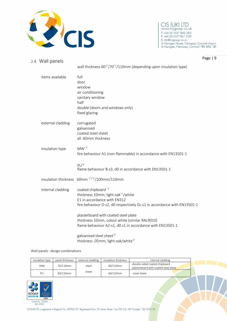
2.4. Wall panels
wall thickness 60’2’/70’1’/110mm (depending upon insulation type)
Page | 9
items available full door window air conditioning sanitary window half double (doors and windows only) fixed glazing
external cladding corrugated
galvanised coated steel sheet all .60mm thickness
insulation type MW ‘1’
fire behaviour A1 (non-flammable) in accordance with EN13501-1
PU‘2’
flame behaviour B-s3, d0 in accordance with EN13501-1
insulation thickness 60mm ’1’/’2’/100mm/110mm
internal cladding coated chipboard ‘1’
thickness 10mm; light oak’1’/white E1 in accordance with EN312 fire behaviour D-s2, d0 respectively Dfl-s1 in accordance with EN13501-1
plasterboard with coated steel plate thickness 10mm, colour white (similar RAL9010) flame behaviour A2-s1, d0 s1 in accordance with EN13501-1
galvanised steel sheet’2’
thickness .05mm; light oak/white’2’
Wall panels : design combinations
insulation type panel thickness external cladding insulation thickness internal cladding
MW 70/110mm steel 60/110mm -double-sided coated chipboard -plasterboard with coated steel plate
PU 60/110mm sheet
60/110mm - steel sheet

2.5. Partition walls items available full panel
door panel window panel half panel
wooden construction ‘1’
total thickness 60mm wooden frame thickness 40mm
cladding(both sides) double-sided, coated chipboard 10mm thick
light oak/white E1 in accordance with EN312 fire behaviour D-s2, d0 Dfl-s1 in accordance with EN13501-1
steel version ‘2’ total thickness 60mm
frame wooden frame with cardboard comb; thickness 60mm
cladding cladded on both sides; laminated steel plate thickness 0.5mm; colour white (similar RAL9010)
PU specification total thickness 45mm (only CAH 2.591mm) cladding on both sides; galvanised steel sheet thickness 0.50mm, light oak
insulation PU fire behaviour B-s3, d0 in accordance with EN13501-1
Page | 10
2.6. Doors design in accordance with DIN regulations right- or left-hand hinged inward or outward opening steel frame with triangular wrap-around sealing door blade with galvanised steel sheets on both sides
NOMINAL DIMENSIONS CLEAR OPENING
625 x 2000 mm (Internal/WC only) 561 x 1940 mm
875 x 2000 mm’1’/’2’ 811 x 1940 mm
1000 x 2000 mm 936 x 1940 mm
2000 x 2000 mm inactive leaf with concealed frame joint
1936 x 1940 mm
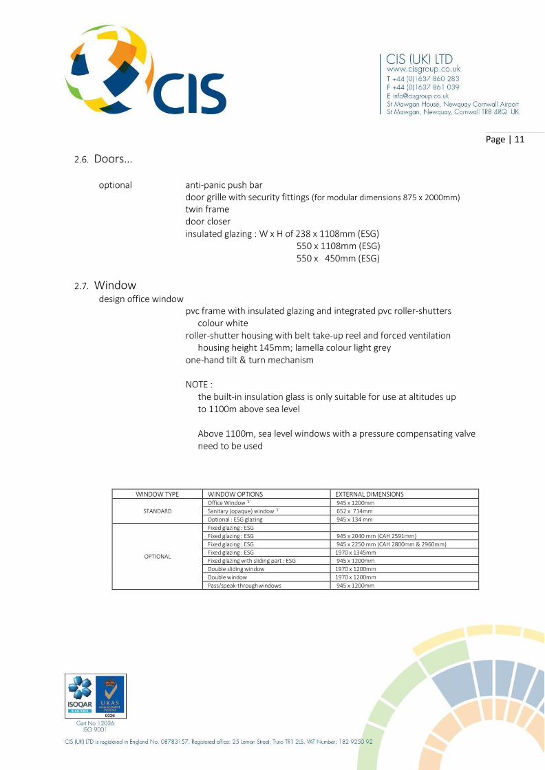
2.6. Doors…
optional anti-panic push bar door grille with security fittings (for modular dimensions 875 x 2000mm)
twin frame door closer insulated glazing : W x H of 238 x 1108mm (ESG)
550 x 1108mm (ESG) 550 x 450mm (ESG)
Page | 11
2.7. Window design office window
pvc frame with insulated glazing and integrated pvc roller-shutters
colour white roller-shutter housing with belt take-up reel and forced ventilation
housing height 145mm; lamella colour light grey one-hand tilt & turn mechanism
NOTE : the built-in insulation glass is only suitable for use at altitudes up to 1100m above sea level
Above 1100m, sea level windows with a pressure compensating valve need to be used
WINDOW TYPE WINDOW OPTIONS EXTERNAL DIMENSIONS
STANDARD
Office Window ‘1’ 945 x 1200mm
Sanitary (opaque) window ‘2’ 652 x 714mm
Optional : ESG glazing 945 x 134 mm
OPTIONAL
Fixed glazing : ESG Fixed glazing : ESG 945 x 2040 mm (CAH 2591mm)
Fixed glazing : ESG 945 x 2250 mm (CAH 2800mm & 2960mm)
Fixed glazing : ESG 1970 x 1345mm
Fixed glazing with sliding part : ESG 945 x 1200mm
Double sliding window 1970 x 1200mm
Double window 1970 x 1200mm
Pass/speak-through windows 945 x 1200mm

2.7. Window… window parapet : the vertical distance between floor level and upper edge of the lower profile of the window frame
Page | 12
office window (CAH 2591mm) 870mm’1’
office window (CAH 2800mm) 1030mm office window (CAH 2960mm) 1030mm
optional window (CAH 2800mm) 870mm optional window (CAH 2960mm) 870mm
sanitary window 1525mm
optional window grille (office & sanitary windows ventilation slider inside roller-shutter housing security glazing on office windows foamed aluminium roller-shutters with chain tension cords and
roller-shutter rails
3. Electrical installation Specification concealed cabling
IP20’1’/IP44’2’
plug insert according to country standards (VDE,CH,GB,F,CZ/SK,DK) country-specific design/variations possible
3.1 Technical Data
basis VDE (= OEVE, SKAN,CZ/SK) F GB CH/DK
connection recessed CEE external plug & socket connections
230V/3 poles/32A ‘1’/’2’ voltage
400V/5 poles/32A ‘1’/‘2’
frequency 50 Hz
protection residual current operated device 40A/0.03A’1’ /‘2’/4 poles (400V)
residual current operated device 63a/0.03A/2 poles (230V)’1’/’2’
distribution board distribution box; surface-mounted type; single/twin row ‘1’
distribution box; surface-mounted type; single/twin row wet room ‘2’
cable (N) YM-J/H05 VV-F R02V (N YM-J/H05 VV-F
electrical circuits
light : circuit breaker 10A, 2 poles (3 x 1.5mm2) ‘1’/’2’
heating : circuit breaker 13A, 2 poles (3 X 1.52) ‘1’/’2’
socket : circuit breaker 13A, 2 poles (3 x 2.5mm2) ‘1’/’2’
circuit breakder a-A, 2 poles (3x1.5mm2)
socket 2 x earthed twin wall sockets ‘1’ (office cabin 20’)
3 x earthed single sockets ‘2’ (sanitary cabin 20’)
lighting light switch ‘1’/’2’
2 x twin batten fluorescent light tubes with plastic covering 2 x 36W ‘1’ (office cabin 20’)
2 x single light with trough & fluorescent tube 1 x 36W ‘2’ (sanitary cabin 20’)

3.1 Technical Data …
Optional category 2 light fittings 2 x 36W light with bulb 25W spur
In accordance with CENELEC regulations
HD 60364-1:2008 HD 60364-4-441:2007 HD 60364-7-717:2004 HD 60364-7-701:2007 HD 384.4.482 S1:1997 HD 384.7.711 S1:2003
earthing universally useable grounding terminal
on both short sides in the floor frame of each corner, a drill hole with a diameter of 9.4mm is prepared for the fixture of the grounding terminal
the fitting of the grounding terminal is undertaken with a screw M10 with a self-cutting screw thread
the screw positioning is carried out in the factory on a suitable spot n the cabin
a grounding terminal and four-wire connector are delivered with the Cabin to be fitted by the customer, on site
the protective earthing installation on site must be carried out by the buyer/hirer
wiring fixed cabling depending on panel configuration and the user ‘1’/’2’
flexible cable system with plug contact and full length cables ‘1’/’2’
Safety Advice : The cabins may be linked electrically at the external CEE plugs and sockets
The decision on how many units to connect to the power supply will depend on the expected constant current in the linked circuits
Commissioning must be carried out by an approved electrician
Page | 13

3.1 Technical Data …
Safety Advice : the manual for the assembly, start up, utilisation and maintenance of the electrical installations is delivered in the fuse box and must be followed
before connecting to the low voltage grid, all appliances (consumer loads) must be switched off and earthing ensured (earthing feed cable and earthing connecting lines between cabins must be checked on potential equity and low Ohm levels)
attention : the supply and connection cables are made for an operating voltage of max. 32 Ampere
these are not secured with an over-current protection device
connection of the cabins to an external power supply may only be undertaken by an authorised, specialist company
cleaning with a high-pressure cleaner is FORBIDDEN cabin electrical equipment may not be cleaned by a direct water jet under any circumstances
if Cabins are delivered to areas with increased lightning activity, further measurements have to be taken to prevent over-voltage, depending on the country’s specific rules
where machines or appliances with high start-up current peaks are used (according to the equipment manuals), adequate RCD/MCB must be used
cabin electric fittings are designed for minimal exposure to vibration; if subject to higher exposures, measurements need to be taken in accordance with country-specific rules
the cabins are designed for areas of little seismic activity. If the cabins are used in areas with higher activity, the country’s national regulations are valid and the equipment needs to be adjusted accordingly
the choice of external linking cables between cabins must comply with the country’s national technical regulations
the cabins must be secured against thermal overload with a type gL fuse of gG with max. IN = 32A
Page | 14

3.2 Heating and air conditioning
Individual heating through frost heaters, thermostatically controlled electric convectors and/or fan heaters with safety switch for over-heating; alternative options for heating/cooling are available upon request
Mechanical ventilation options with electrical ventilators or, at user’s request, also available with window air conditioning units
Regular room ventilation must be provided; a relative humidity of 60% should not be exceeded to prevent condensation
Page | 15
output
DESCRIPTION
(amount depends on Cabin type)
ventilator ‘2’ 170m3/h
hydrostatic ventilator 170m3/h
gas heating 2kW
air conditioning 2.6kW
convector heater ‘1’ 2kW
fan heater ‘2’ 2kW
frost heater 0.5kW
4. Miscellaneous 4.1 Transport height
The office cabins can be delivered flat-packed Standard pack height is 648mm Four cabins stacked on top of each other have the same external dimensions as a fully- assembled cabin
TransPak height (office cabins only & depending on equipment)
864mm : standard for CAH2800mm & 2960mm x 6 per vehicle 648mm : standard for CAH2591 x 8 per vehicle 515mm: depending on layout x 10 per vehicle
4.2 Construction/Assembly/Statics/Servicing General information : each cabin must be placed on foundations provided on site e.g. wood, concrete, with at least
4 points of support for 10’ cabins 6 points of support for 16’ or 20’ cabins (see document 6.5 attached) 8 points of support for 30’ cabins (see document 6.6 attached)

4.2 Construction/Assembly/Statics/Servicing…
Foundation dimensions have to be adapted to local conditions, norms and frost line, taking into account local soil conditions and maximum possible loads
A level foundation is a pre-conditions for smooth, failure-free assembly and ongoing stability
During set-up or placement, maximum permitted loads and regional conditions such as snow loads must be taken into account
Cabin combination Individual cabins can be configured next to; behind or on top of each other but structure indications and maximum possible loads must be considered
for ground (single-level) construction, the cabins may be placed arbitrarily and without restriction regarding quantity
2- and 3-storey construction, the combination possibilities presented in
appendix 6.1, 6.2 (10’, 16’ & 20’ cabins) appendix 6.3, 6.4 (24’ & 30’ cabins) must be followed
Should the cabins be linked in combinations other than those described in the documents above, we can give no statement with reference to the maximum wind permitted loads
We categorically recommend that alternative combinations are not erected or only if they meet local requirements and under supervision by approved and authorised experts
Cabins must be stacked exactly on top of each other; the special CMU-stacking cones must be used
The Cabin roof is not suitable for storage of goods or materials
The assembly manuals must be followed The service notes provided by CIS (UK) Ltd must be adhered to
Sanitary fittings : after connection, all water circulation must be checked for integrity in case, for example, of loosening during transport
CIS (UK) LTD denies any warranty for damages that may result from placement contrary to the principles herein Liability for consequential damages on principle
Page | 16

Page | 17
4.3 Handling with forklift by crane ; angle between lifting rope & horizontal line to be at least 60o
construction and design constraints mean that handling with a spreader is not permitted (Appendix 6.7/6.8)
4.4 Certification Germanischer Lloyd ‘type test’ (except 24’ and 30’ office cabin)
4.5 Paint Paint system with high weather & ageing durability; suitable for city and industry atmosphere Wall panels : 25µ coating thickness Frame : 15-40µ base coat
40-60µ top coat Although the components above are painted using different application methods, this produces shades similar to RAL, we do not accept liability for colour variations in comparison with the RAL tones
5. Equipment and fixtures options for sanitary and office cabins cabins
accessible fixtures for special needs water installation (supply and drain) floor drainage channel/gulley metal mirror moulded floor covering (wet-rooms) mini kitchen boiler 80L, 150L, 300L paper towel dispenser pressure-reducing valve country-sunk sanitary connections shower cubicle with folding door intermediate panel
shower cubicle with curtain soap dispenser single lever taps for all applications stop/go fixtures for hand basins & showers wet room electrics (FR electric) ethernet & communications facilties inc.
satellite capability GFK hand wash trough with 2 x basins urinal (1 x 1200mm) GFK hand wash trough with 4 x basins canopy roof (large/small) (1 x 2400mm) electric hand dryer additional water supply ceramic handwash basin WC cabin WC undersink water heater 5L
coat hook Fire-rated components :
roof section: Class E160 fire resistance in accordance with EN13501-1 wall elements : Class E190 in accordance with EN13501-1

Page | 18
5.1 WATER INSTALLATION supply using ½”, ¾” or 1” pipe, sideways through cabin wall internal PVC pipework operating pressure :
4bar is maximum permitted operating/connection pressure warm water preparation :
electric boilers, depending upon cabin type (80L, 150L or 3002L)
Attention : boilers with 50/150/300L capacity are suitable for a max. operating pressure of 6bar Higher water pressure is reduced by a PRV
discharge : waste water is collected by PVC pipes, DN50, DN100 or DN125 (external diameter 50,110,125mm) and discharged sideways through cabin wall)
discharge of waste water into an authorised sewage network has to be undertaken by the user in compliance with the official regulations for faecal waste and water
Further technical information upon request
Regulatory and legal requirements for the storage, placement and useage of the cabins must be considered by the buyer
Suitability of the cabin (modular building) with associated fixtures and fittings must also be examined by the user for suitability for purpose
This document is subject to technical alterations
End as/cp


