PAGE 1 OF 2 SERVICE PARTS LIST BULLETIN NO.service parts list 54-43-0070 bulletin no. 00 0 example:...
4
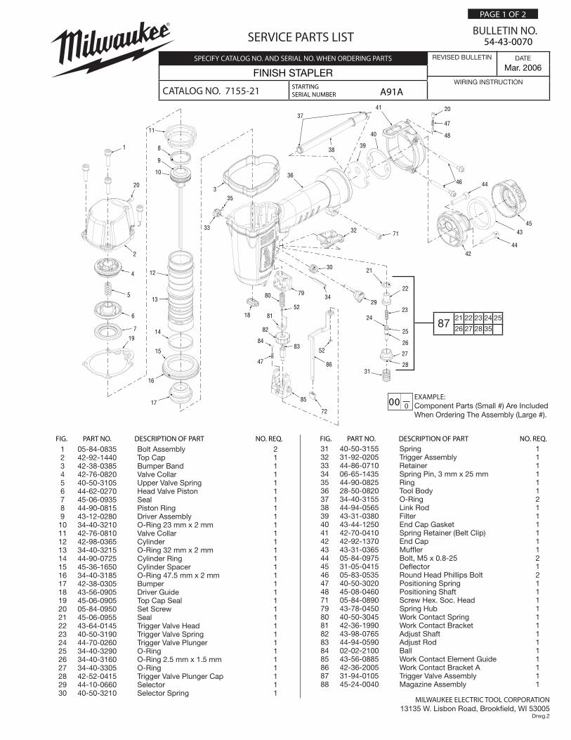
MILWAUKEE ELECTRIC TOOL CORPORATION 13135 W. Lisbon Road, Brookfield, WI 53005 Drwg.2 54-43-0070 SERVICE PARTS LIST BULLETIN NO. 0 00 EXAMPLE: Component Parts (Small #) Are Included When Ordering The Assembly (Large #). PAGE 1 OF 2 FIG. PART NO. DESCRIPTION OF PART NO. REQ. A91A REVISED BULLETIN DATE Mar. 2006 WIRING INSTRUCTION STARTING SERIAL NUMBER SPECIFY CATALOG NO. AND SERIAL NO. WHEN ORDERING PARTS FINISH STAPLER CATALOG NO. 7155-21 1 05-84-0835 Bolt Assembly 2 2 42-92-1440 Top Cap 1 3 42-38-0385 Bumper Band 1 4 42-76-0820 Valve Collar 1 5 40-50-3105 Upper Valve Spring 1 6 44-62-0270 Head Valve Piston 1 7 45-06-0935 Seal 1 8 44-90-0815 Piston Ring 1 9 43-12-0280 Driver Assembly 1 10 34-40-3210 O-Ring 23 mm x 2 mm 1 11 42-76-0810 Valve Collar 1 12 42-98-0365 Cylinder 1 13 34-40-3215 O-Ring 32 mm x 2 mm 1 14 44-90-0725 Cylinder Ring 1 15 45-36-1650 Cylinder Spacer 1 16 34-40-3185 O-Ring 47.5 mm x 2 mm 1 17 42-38-0305 Bumper 1 18 43-56-0905 Driver Guide 1 19 45-06-0905 Top Cap Seal 1 20 05-84-0950 Set Screw 1 21 45-06-0955 Seal 1 22 43-64-0145 Trigger Valve Head 1 23 40-50-3190 Trigger Valve Spring 1 24 44-70-0260 Trigger Valve Plunger 1 25 34-40-3290 O-Ring 1 26 34-40-3160 O-Ring 2.5 mm x 1.5 mm 1 27 34-40-3305 O-Ring 1 28 42-52-0415 Trigger Valve Plunger Cap 1 29 44-10-0660 Selector 1 30 40-50-3210 Selector Spring 1 31 40-50-3155 Spring 1 32 31-92-0205 Trigger Assembly 1 33 44-86-0710 Retainer 1 34 06-65-1435 Spring Pin, 3 mm x 25 mm 1 35 44-90-0825 Ring 1 36 28-50-0820 Tool Body 1 37 34-40-3155 O-Ring 2 38 44-94-0565 Link Rod 1 39 43-31-0380 Filter 1 40 43-44-1250 End Cap Gasket 1 41 42-70-0410 Spring Retainer (Belt Clip) 1 42 42-92-1370 End Cap 1 43 43-31-0365 Muffler 1 44 05-84-0975 Bolt, M5 x 0.8-25 2 45 31-05-0415 Deflector 1 46 05-83-0535 Round Head Phillips Bolt 2 47 40-50-3020 Positioning Spring 1 48 45-08-0460 Positioning Shaft 1 71 05-84-0890 Screw Hex. Soc. Head 1 79 43-78-0450 Spring Hub 1 80 40-50-3045 Work Contact Spring 1 81 42-36-1990 Work Contact Bracket 1 82 43-98-0765 Adjust Shaft 1 83 44-94-0590 Adjust Rod 1 84 02-02-2100 Ball 1 85 43-56-0885 Work Contact Element Guide 1 86 42-36-2005 Work Contact Bracket A 1 87 31-94-0105 Trigger Valve Assembly 1 88 45-24-0040 Magazine Assembly 1 87 21 22 23 24 25 26 27 28 35 FIG. PART NO. DESCRIPTION OF PART NO. REQ. 1 2 4 5 6 7 9 8 3 20 19 11 10 12 13 14 15 16 17 85 72 84 47 52 86 81 82 83 52 80 79 18 35 33 30 34 29 32 71 36 42 44 43 45 46 20 47 48 22 23 25 26 27 28 21 24 31 37 38 39 40 41 44
Transcript of PAGE 1 OF 2 SERVICE PARTS LIST BULLETIN NO.service parts list 54-43-0070 bulletin no. 00 0 example:...
MILWAUKEE ELECTRIC TOOL CORPORATION13135 W. Lisbon Road, Brookfield, WI 53005
Drwg.2
54-43-0070SERVICE PARTS LIST BULLETIN NO.
000 EXAMPLE:Component Parts (Small #) Are Included When Ordering The Assembly (Large #).
PAGE 1 OF 2
FIG. PART NO. DESCRIPTION OF PART NO. REQ.
A91A
REVISED BULLETIN DATE
Mar. 2006
WIRING INSTRUCTIONSTARTINGSERIAL NUMBER
SPECIFY CATALOG NO. AND SERIAL NO. WHEN ORDERING PARTS
FINISH STAPLER
CATALOG NO. 7155-21
1 05-84-0835 Bolt Assembly 2 2 42-92-1440 Top Cap 1 3 42-38-0385 Bumper Band 1 4 42-76-0820 Valve Collar 1 5 40-50-3105 Upper Valve Spring 1 6 44-62-0270 Head Valve Piston 1 7 45-06-0935 Seal 1 8 44-90-0815 Piston Ring 1 9 43-12-0280 Driver Assembly 1 10 34-40-3210 O-Ring 23 mm x 2 mm 1 11 42-76-0810 Valve Collar 1 12 42-98-0365 Cylinder 1 13 34-40-3215 O-Ring 32 mm x 2 mm 1 14 44-90-0725 Cylinder Ring 1 15 45-36-1650 Cylinder Spacer 1 16 34-40-3185 O-Ring 47.5 mm x 2 mm 1 17 42-38-0305 Bumper 1 18 43-56-0905 Driver Guide 1 19 45-06-0905 Top Cap Seal 1 20 05-84-0950 Set Screw 1 21 45-06-0955 Seal 1 22 43-64-0145 Trigger Valve Head 1 23 40-50-3190 Trigger Valve Spring 1 24 44-70-0260 Trigger Valve Plunger 1 25 34-40-3290 O-Ring 1 26 34-40-3160 O-Ring 2.5 mm x 1.5 mm 1 27 34-40-3305 O-Ring 1 28 42-52-0415 Trigger Valve Plunger Cap 1 29 44-10-0660 Selector 1 30 40-50-3210 Selector Spring 1
31 40-50-3155 Spring 1 32 31-92-0205 Trigger Assembly 1 33 44-86-0710 Retainer 1 34 06-65-1435 Spring Pin, 3 mm x 25 mm 1 35 44-90-0825 Ring 1 36 28-50-0820 Tool Body 1 37 34-40-3155 O-Ring 2 38 44-94-0565 Link Rod 1 39 43-31-0380 Filter 1 40 43-44-1250 End Cap Gasket 1 41 42-70-0410 Spring Retainer (Belt Clip) 1 42 42-92-1370 End Cap 1 43 43-31-0365 Muffler 1 44 05-84-0975 Bolt, M5 x 0.8-25 2 45 31-05-0415 Deflector 1 46 05-83-0535 Round Head Phillips Bolt 2 47 40-50-3020 Positioning Spring 1 48 45-08-0460 Positioning Shaft 1 71 05-84-0890 Screw Hex. Soc. Head 1 79 43-78-0450 Spring Hub 1 80 40-50-3045 Work Contact Spring 1 81 42-36-1990 Work Contact Bracket 1 82 43-98-0765 Adjust Shaft 1 83 44-94-0590 Adjust Rod 1 84 02-02-2100 Ball 1 85 43-56-0885 Work Contact Element Guide 1 86 42-36-2005 Work Contact Bracket A 1 87 31-94-0105 Trigger Valve Assembly 1 88 45-24-0040 Magazine Assembly 1
8721 22 23 24 25
26 27 28 35
FIG. PART NO. DESCRIPTION OF PART NO. REQ.
1
2
4
5
6
7
9
8
320
19
11
10
12
13
14
15
16
17 85
72
84
47
52
86
81
82
83
52
80 79
18
35
33
30
3429
32 71
36
4244
4345
46
20
47
48
22
23
25
26
27
28
21
24
31
37
3839
40
41
44
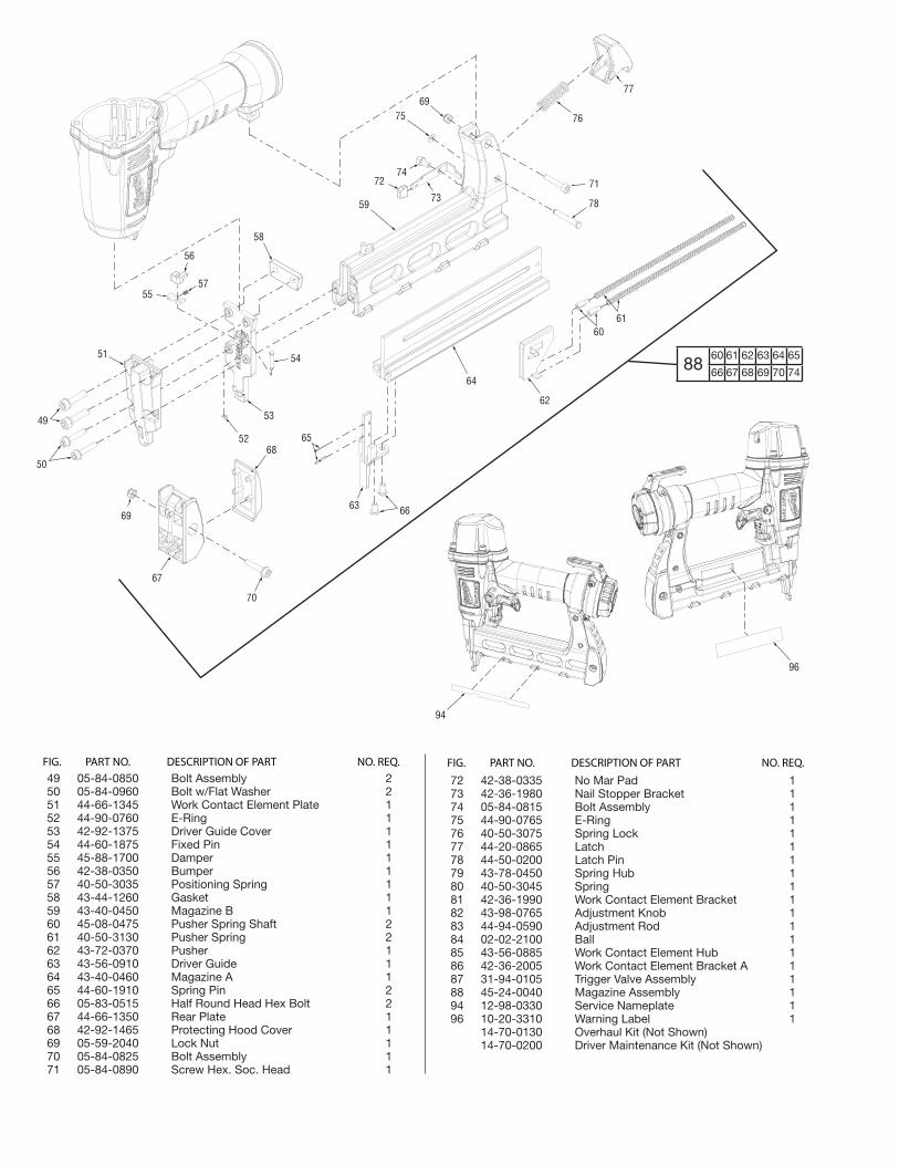
49 05-84-0850 Bolt Assembly 2 50 05-84-0960 Bolt w/Flat Washer 2 51 44-66-1345 Work Contact Element Plate 1 52 44-90-0760 E-Ring 1 53 42-92-1375 Driver Guide Cover 1 54 44-60-1875 Fixed Pin 1 55 45-88-1700 Damper 1 56 42-38-0350 Bumper 1 57 40-50-3035 Positioning Spring 1 58 43-44-1260 Gasket 1 59 43-40-0450 Magazine B 1 60 45-08-0475 Pusher Spring Shaft 2 61 40-50-3130 Pusher Spring 2 62 43-72-0370 Pusher 1 63 43-56-0910 Driver Guide 1 64 43-40-0460 Magazine A 1 65 44-60-1910 Spring Pin 2 66 05-83-0515 Half Round Head Hex Bolt 2 67 44-66-1350 Rear Plate 1 68 42-92-1465 Protecting Hood Cover 1 69 05-59-2040 Lock Nut 1 70 05-84-0825 Bolt Assembly 1 71 05-84-0890 Screw Hex. Soc. Head 1
72 42-38-0335 No Mar Pad 1 73 42-36-1980 Nail Stopper Bracket 1 74 05-84-0815 Bolt Assembly 1 75 44-90-0765 E-Ring 1 76 40-50-3075 Spring Lock 1 77 44-20-0865 Latch 1 78 44-50-0200 Latch Pin 1 79 43-78-0450 Spring Hub 1 80 40-50-3045 Spring 1 81 42-36-1990 Work Contact Element Bracket 1 82 43-98-0765 Adjustment Knob 1 83 44-94-0590 Adjustment Rod 1 84 02-02-2100 Ball 1 85 43-56-0885 Work Contact Element Hub 1 86 42-36-2005 Work Contact Element Bracket A 1 87 31-94-0105 Trigger Valve Assembly 1 88 45-24-0040 Magazine Assembly 1 94 12-98-0330 Service Nameplate 1 96 10-20-3310 Warning Label 1 14-70-0130 Overhaul Kit (Not Shown) 14-70-0200 Driver Maintenance Kit (Not Shown)
8860 61 62 63 64 65
66 67 68 69 70 74
FIG. PART NO. DESCRIPTION OF PART NO. REQ. FIG. PART NO. DESCRIPTION OF PART NO. REQ.
69
67
70
686552
53
63 66
58
54
55
56
57
51
49
50
64
62
6061
71
78
76
7769
75
7472
5973
94
96
PAGE 2 OF 2BULLETIN NO. 54-43-0070 Mar. 2006
Disassembly:
1, 2 Remove hex bolts (1) from top cap (2) using a 4 mm hex key.
2, 4, 5, 6, 7 Remove valve assembly (4, 5, 6, and 7) from top cap (2) using a flat blade screwdriver.
11, 12 Remove press ring (11) from top of cylinder (12) prior to removing driver/cylinder assemblies.
8, 9, 10, 12, 13, 14, 16, 17, 36
Remove driver assembly (8, 9, 10) and cylinder assembly (12, 13, 14, and 17) from tool body (36) at the same time by placing two flat blade screwdrivers under ring of cylinder (12) 180° apart, and gently prying the cylinder from the tool body. Note: Valve bumper (17) may stay in cylinder (12) or remain in tool body (36).
15, 16, 36 Remove cylinder spacer (15) and O-Ring (16) from tool body (36) by placing a flat blade screwdriver under spacer (15) and gently lifting spacer assembly out of the tool body (36).
59, 64 72, 73 Remove magazine A (64) from magazine B (59) by removing screw washer (74) and nail stopper bracket assembly (72 and 73).
29, 30, 31, 32, 33, 35 Remove selector assembly (29, 30, 33, 35), and trigger assembly (31,32) from tool body (36) by placing a 3/32 in. (2.5 mm) punch inside half-moon slot of retainer (33) and gently tapping shaft of selector (29) to separate retainer (33) from shaft (29). Remove spring (30), retainer (33) ring (35), spring, (31) and trigger (32) from tool body.
21, 22 23, 24, 25, 26, 27, 28, 36
Remove trigger valve plunger cap (28) from tool body (36) using an 8 mm wrench. Remove remaining trigger valve components (21-27).
20, 41, 42, 46 Remove belt clip (41) from end cap (42) by removing bolts (46) and loosening set screw (20) only a few turns counterclockwise.
42, 45 Remove deflector (45) from end cap (42) using a flat blade screwdriver. Note: Using excessive force will damage or destroy deflector.
Re-Assembly:
21, 22, 23, 24, 25, 26, 27, 28, 36
Reinstall trigger valve assembly components (21-28) into tool body (36) in order shown. Thread assembly into tool body (36) by hand a couple of turns to insure external threads on trigger valve plunger cap (28) properly engage with internal threads inside tool body (36). Secure assembly using an 8 mm wrench.
24, 29, 30, 31, 32, 33, 35,
Reinstall selection lever assembly (29, 30, 33, 35,) and trigger assembly (31 and 32) by doing the following.• Place spring (30) onto shaft of selection lever (29). • Position spring (31) and trigger (32) over plunger of trigger valve assembly (26). • Insert selection lever assembly (29 and 30) into tool body (36) and align half-moon slot of retainer (33) with half-
moon shaft of selection lever (29) and snap retainer assembly (33 and 35) onto the shaft.
9, 36 Install flat side of driver guide blade (9) towards trigger assembly (32).
12, 14 Reinstall cylinder ring (14) onto cylinder (12) with large flanged end facing the top of cylinder (12).
8, 9, 10, 12, 13, 14, 15, 16, 17, 36
Reassemble driver assembly (8, 9, 10), and cylinder assembly (12, 13, and 14) and combine the two together. Set aside. Install cylinder spacer assembly (15, 16) and valve bumper (17) into tool body (36). Install assembly into tool body.
6, 14, 19 Reinstall press ring (11) onto top of cylinder (12) with wide edge facing toward top cap (2).
2, 4, 5, 6, 7 Reinstall valve collar (4) into internal bore of top cap (2). Place upper valve spring (5) into center of valve collar (4) and push head valve piston assembly (6 and7) into top cap, applying sufficient pressure to insure seal and collar fit into position inside top cap (2).
1, 2, 4, 5, 6, 7, 36 Reinstall top cap assembly (2, 4, 5, 6, 7) onto tool body (36) and install hex bolts (1). Note: To properly seat top cap, tighten the screws at alternating corners a few turns at a time until all screws are secure.
59, 64, 72, 73 Reinstall magazine A (64) into magazine B (59) and install screw/washer and nail stopper bracket assembly (72 and 73).
39, 42 Install smooth side of filter (39) toward end cap (42).
20, 41, 42, 46 Reassemble belt clip (41) onto end cap (42) and tighten set screw (20) until it’s flush with the top thread of the clip and Install bolts (46).
1, 44, 49, 50, 66, 74 Apply Blue Loctite® 242 to fasteners 1, 44, 49, 50, 66, and 74.

Lubrication:
Type I Grease 49-08-7100
Clean all parts with a dry, clean cloth.
2, 4, 5, 6, 7 Place a thin coating of grease into internal bore of top cap (2). Coat parts (4-7) and reassemble in order shown.
8, 9, 10 Coat O-Ring (10) and piston ring (8) prior to installing into groove of driver assembly (9).
18, 20, 23, 24 Coat O-Ring (13), cylinder spacer (15), O-Ring (16) and cylinder ring (14) prior to installing onto cylinder (12).
21, 22 23, 24, 25, 26 27, 28
Coat individual parts of the trigger valve assembly (21-27). Note: Plunger cover (28) does not require lubrication.