Page 1 Karara Iron Ore TSF – design considerations for a ......
11
Page 1 Karara Iron Ore TSF – design considerations for a unique large scale dry stack facility C. Hore SRK Consulting, Perth, Western Australia, Australia D. Luppnow SRK Consulting, Perth, Western Australia, Australia This paper was first presented at the Tailings and Mine Waste 14 Conference in Keystone Colorado on 5-8 October 2014. Abstract Globally, mine operators are becoming increasingly aware of water availability costs and constraints. This is leading to a trend of de-watering tailings disposal particularly where fresh water is required for processing. The Karara Mining Limited operation located in the Mid-west of Western Australia selected a large scale dry stack facility for their tailings disposal and storage largely for this reason. There are a range of considerations which must be made when designing and operating a large scale dry stack facility, which relates to both the traditional tailings material parameters, and conveyor and stacker properties. The Karara facility operates a 35,000 tpd capacity stacker and conveyor system to develop a tailings dry stack landform. Key issues such as stability of the tailings mass and stacker foundation, storage capacity, landform development and closure considerations were considered during the design phase and permitting. These have been re-evaluated and updated during commissioning and subsequent operations, along with statutory reporting. This paper presents a case study of the design considerations for a unique large scale dry stack facility. Design analyses from feasibility and detailed engineering stages are presented along with discussion related to updated operational testing. The paper will provide insight into operating issues that may impact the decision processes of potential future similar operations. Introduction The Karara Iron Ore Mine operated by Karara Mining Limited (KML) is located approximately 70km east from Morawa in the mid-west region of Western Australia. The operation mines magnetite iron ore associated with banded iron formation (BIF) ridges and has a nameplate capacity of approximately 8 Mt per annum of magnetite concentrate. At that production rate the plant will produce approximately 1,600 dry tonnes per hour (tph) of de-watered tailings material. The dewatered tailings are deposited by a radial stacker at a dry stack tailings storage facility (TSF). The selection of a dry stack tailings storage facility for the Karara iron ore mine was made based on a combination of key drivers. The specification for the magnetite concentrate typically has a limit on the chloride content. To produce a product within the chloride specification there were two options (in the West Australian context); one, utilise saline water in the processing and later wash the concentrate prior to loading to remove excess salt. Or, two, the process could utilise fresh water in the processing and thereby remove the requirement for washing. The fresh water processing option was selected by KML. However, with the evaporation exceeding precipitation by approximately 10:1 (annual average precipitation 310 mm, annual average evaporation 3,875 mm) and the majority of the groundwater in the area being saline, the availability of freshwater in the mine area is scarce. A freshwater aquifer was available some distance away, but the available allocation from this aquifer could not sustain the full mine make-up water requirement for any tailings disposal strategy other than filtering and dry stacking. The tailings material consists of two-sized fractions co-disposed onto a belt conveyor and conveyed to the tailings facility. The two tailings products, namely coarse and fine, are mechanically dewatered to around 15% moisture (mw/ms). The coarse tailings material is dewatered via screens and the fines by mechanical press filtration. 8 December 2014
Transcript of Page 1 Karara Iron Ore TSF – design considerations for a ......

Page 1
Karara Iron Ore TSF – design considerations for a unique large scale dry stack facility
C. Hore SRK Consulting, Perth, Western Australia, Australia
D. Luppnow
SRK Consulting, Perth, Western Australia, Australia
This paper was first presented at the Tailings and Mine Waste 14 Conference in Keystone Colorado on 5-8 October 2014. Abstract Globally, mine operators are becoming increasingly aware of water availability costs and constraints. This is leading to a trend of de-watering tailings disposal particularly where fresh water is required for processing. The Karara Mining Limited operation located in the Mid-west of Western Australia selected a large scale dry stack facility for their tailings disposal and storage largely for this reason. There are a range of considerations which must be made when designing and operating a large scale dry stack facility, which relates to both the traditional tailings material parameters, and conveyor and stacker properties. The Karara facility operates a 35,000 tpd capacity stacker and conveyor system to develop a tailings dry stack landform. Key issues such as stability of the tailings mass and stacker foundation, storage capacity, landform development and closure considerations were considered during the design phase and permitting. These have been re-evaluated and updated during commissioning and subsequent operations, along with statutory reporting. This paper presents a case study of the design considerations for a unique large scale dry stack facility. Design analyses from feasibility and detailed engineering stages are presented along with discussion related to updated operational testing. The paper will provide insight into operating issues that may impact the decision processes of potential future similar operations.
Introduction The Karara Iron Ore Mine operated by Karara Mining Limited (KML) is located approximately 70km east from Morawa in the mid-west region of Western Australia. The operation mines magnetite iron ore associated with banded iron formation (BIF) ridges and has a nameplate capacity of approximately 8 Mt per annum of magnetite concentrate. At that production rate the plant will produce approximately 1,600 dry tonnes per hour (tph) of de-watered tailings material. The dewatered tailings are deposited by a radial stacker at a dry stack tailings storage facility (TSF). The selection of a dry stack tailings storage facility for the Karara iron ore mine was made based on a combination of key drivers. The specification for the magnetite concentrate typically has a limit on the chloride content. To produce a product within the chloride specification there were two options (in the West Australian context); one, utilise saline water in the processing and later wash the concentrate prior to loading to remove excess salt. Or, two, the process could utilise fresh water in the processing and thereby remove the requirement for washing. The fresh water processing option was selected by KML. However, with the evaporation exceeding precipitation by approximately 10:1 (annual average precipitation 310 mm, annual average evaporation 3,875 mm) and the majority of the groundwater in the area being saline, the availability of freshwater in the mine area is scarce. A freshwater aquifer was available some distance away, but the available allocation from this aquifer could not sustain the full mine make-up water requirement for any tailings disposal strategy other than filtering and dry stacking. The tailings material consists of two-sized fractions co-disposed onto a belt conveyor and conveyed to the tailings facility. The two tailings products, namely coarse and fine, are mechanically dewatered to around 15% moisture (mw/ms). The coarse tailings material is dewatered via screens and the fines by mechanical press filtration.
8 December 2014

SRK Consulting Page 2
The terrain in the mine area is flat, with the only relief provided by the BIF ridge that is Mt Karara, and it will ultimately be mined to below the natural ground. There are no identifiable streambeds and most precipitation run-off is via sheet flow. The following additional design criteria were provided for use in the feasibility design: • Coarse stream 80% minus 1.5 mm • Fine stream 80% minus 35 micron • 50/50 blend of coarse and fine • Delivered tailings maximum moisture limit 18% • 27 year tailings facility design life • Operation to be 24 hours per day 365 days per year with an operating availability of 90.2 % or 7,900 hours
per year. • Life of facility design tonnage is approximately 320 million tonnes. As the tailings are filtered to low moisture content (i.e. would not flow), pumping was discounted as a transport method. Options for transport of the tailings to the TSF were narrowed down to the following possible options based on the tailings being conveyed to a surge bin close to the disposal area: • Truck the tailings from the surge bin location to the final disposal location within the TSF footprint; • Convey the tailings from the surge bin location to a final disposal location within the TSF footprint using an
overland conveyor/radial stacker arrangement; or • A combination of trucking and conveying, i.e. trucks for a limited number of years to offset initial capital
expenditure and after which conveyors will be used. The client went through a selection process between the above options and selected the stacking only option based largely on net present value calculations. DESIGN CONSIDERATIONS The design of the TSF required many considerations some of which are unique to dry stack facilities and others which are common to all TSF’s. This paper presents discussion on the unique aspects that were considered for this facility design. Dry stack configuration A typical TSF configuration is designed minimising fill requirements for embankments in agreement with the local topography. The dry stack layout design is unique due to the inter-dependence of the stack configuration, the conveyor and stacker design, and the design production rate. A change in conveyor type, size or configuration can have a large impact on the intermediate and final stack configuration. Conversely, to achieve a certain stack configuration the stacker and conveyor system must be designed accordingly. Furthermore, the progressive footprint development must be designed for the production rate such that the stacker and conveyor advance rate is kept within practical limitations. The goals of the stack and stacker configuration are too: • Minimise initial and overall footprint • Minimise stacker downtime due to changeovers between lifts and sweeps • Maintain stacker progression rates within practical limitations • Maximise evaporative drying of the stacked tailings • Maximise density of tailings mass • Minimise stacker and conveyor costs (approximately proportional to size/weight) • Allow progressive reclamation and rehabilitation to manage dust The final landform height of the facility was capped by the state permitting at the elevation of other banded iron formations in the area, which provided a maximum TSF height of approximately 90 m on average. The footprint of the TSF was minimised by maximising the height of the stack and calculated to achieve the required total storage volume utilising the closure slope angles. In order to minimise initial footprint and therefore up-front costs, a higher lift height was preferred. An individual lift height of 25 m was selected as a practical maximum. This also worked to minimise the number of lift raises required for the conveyor system. The initial design called for the radial stacker to develop its own
8 December 2014

SRK Consulting Page 3
starter ramp up to the first 25 m lift. However, the design philosophy was changed to a waste rock starter ramp to minimise costs of the stacker features and risks, both to the stacker and of extended shutdown periods. This waste rock starter ramp also provided a barrier between the laydown and offices areas and the tailings stack, and reduced exposed surfaces in the first years prior to concurrent closure being adopted. The configuration of the feed and the disposal conveyors in relation to the starter ramp results in a maximum conveyor angle for the Karara conveyor and stacker configuration of 13 degrees. It was assumed that the combined tailings product will be fully mixed at the discharge locations via the actions of the conveyor transfers and the subsequent dumping of the tailings. With respect to the design of the TSF, the main difference between trucking and conveyors is the possible heights of the individual lifts. The feed conveyor transports the tailings from the Karara process plant to the TSF area onto the ramp conveyor for transport of the tailings up to the initial ramp and onto the radial stacker. In order to allow a bypass of the ramp conveyor in cases where the tailings were inadequate for stacking or the radial stacker was temporarily shut-down, a bypass arrangement and emergency storage area was designed. This bypass and emergency storage area allows a degree of flexibility in the system, such that if there are problems with stacker deposition the effects do not flow back to the plant causing plant shutdowns – which is a high priority. Any tailings deposited in the emergency area can later be manually fed back into the conveyor system for stacking via a separate surge bin. The facility has a series of berms and channels, designed and constructed to separate impacted from non-impacted stormwater runoff. The non-impacted water is intercepted upstream of the facility and directed around it, while impacted water is directed to a downstream water management pond. The stormwater berms were designed to be phased as required for the deposition stages. The intermediate layout of the TSF is presented in Figure 1. This shows the initial ramp and the radial sweeps of the stacker as it progresses. Each sweep has a radius of approximately 300 m and at full production rate will take 250 days to stack. The stormwater diversion channels and berms can be seen surrounding the initial facility, they divert clean water away from the facility and capture and direct impacted water to a separate retention pond. The bypass system and emergency storage area can be seen adjacent to the initial ramp.
Figure 1: Karara Dry stack TSF configuration
8 December 2014

SRK Consulting Page 4
Stacker configuration There are two main options for the stacking configuration; advance stacking or retreat stacking, see Figure 2. The key differences being the location of the stacker relative to the stack and direction of stack progression. The majority of stacking operations in the mining industry are heap leaching projects and this is therefore where the majority of the industry experience lies. Typically in heap leaching, retreat stacking is preferred in order to reduce compaction of the heaped ore. This was not an issue at Karara. The individual lift heights of heap leach pads are also generally lower, due to leaching criteria, than the 25 m selected for the Karara dry stack. Preliminary stacker designs were conceptualised for both concepts, which showed that the stacker required to retreat stack a 20 m slope was excessively large and costly. By advance stacking the stacker unit can be much smaller, although the necessary horizontal reach to obtain a safe set-back distance requires detailed calculation. If retreat stacking was selected this might put the stacker at risk of being inundated with tailings. The tailings material is placed at angle of repose and so there is an inherent risk for minor slips and sloughing of the stack face. This could be exacerbated with tailings moisture fluctuations. Conversely, with advance stacking there is a risk of slope failure causing the stacker to fall; this was investigated in detail and is discussed below.
Figure 2: Potential stacking arrangements
Stability The stability of the dry stack TSF, as with any TSF, requires stability evaluation for different scenarios throughout the life of the facility. The stability scenarios that were analysed during the design phase were a single lift, multiple lifts and the closure final landform. In addition, due to the likely slumping and sloughing of the angle of repose material, it was anticipated that the stacker standing at the edge of the crest of the forming slope would be an unsafe situation. Thus, a safe set-back distance from the stack crest needed to be determined for the stacker tracks in order to calculate the necessary cantilever length of the stacker arm. A target factor of safety (FoS) of 1.3 was used for all intermediate/active slopes, i.e. those being stacked, while a FoS of 1.5 was used for final or overall slopes. The stability analyses were carried out using commercial 2D limit equilibrium stability software. The analyses were undertaken for a stack face slope of 1:1.5(V:H) with the slope heights of 5, 10, 15, 20, and 25 m. The slope angle of 1:1.5 (33.6 degrees) was adopted which is slightly steeper than the internal friction angle (31 degrees). This was to account for a small amount of suction in the unsaturated tailings resulting in a steeper stack angle. The shear strength parameters and the density of tailings were estimated from laboratory test results. The load exerted by the stacker provided by the supplier was modelled in the stability analyses. For each slope height, the analyses were repeated with varying stacker position (in the range of 1-10 m from the top edge of the slope). The configuration of the stability analysis is presented in Figure 3. The critical distance of the slip surface was defined as that yielding a FoS of 1.3; it was measured horizontally on the top of the stack from the slope crest to the initiation of the surface. The analysis showed that the critical slip surface distance increases with the increasing stacker distance, and at some point drops to a distance equal to that calculated for no load conditions. This means that the stacker
8 December 2014

SRK Consulting Page 5
load at distances beyond that point does not have any influence on the stability of the slope. This critical distance was used as the optimum safe distance; Figure 4 presents the results of this analysis for each slope height. It can be seen that for a stack height of 25 m a setback of at least 9.5 m is required. This was incorporated into the stacker design.
Figure 3: Stability analysis configuration to determine stacker set back distance
Figure 4: Safe stacker distance vs slope height plot
8 December 2014

SRK Consulting Page 6
Conveyability Conveyability testing was undertaken to determine the moisture content cut-off criteria for the conveyability of the tailings material. That is, at what moisture content do the tailings become too wet to transport up the ramp conveyor and should therefore be directed to the emergency disposal area. At plant start-up and when processing various ore types, there has been some variability in the ratio/blend of coarse to fine material. The spread of likely ratios was provided by KML process staff; this was used to select the following blends for testing: • Blend 1 - 100% fines • Blend 2 – 80% fines 20% coarse • Blend 3 – 50% fines 50% coarse The variability of the different blends at varying moisture content is shown in Figure 5. At the maximum conveyor angle of 13 degrees the maximum moisture content which will allow efficient conveyability for each blend is summarized in Table 1.
Figure 5: Variability of maximum conveyable moisture content with conveyor angle
Table 1: Conveyability test results summary
Blend Maximum moisture content (%)
100% fine 30%
80% fine 27%
50% fine 16%
Water Balance A water balance was developed to determine the likely water volumes that would report to the TSF and the potential volumes that would drain to the retention pond. The methodology for the dry stack facility water balance was similar to that employed for typical conventional TSF’s in that it is a balance of inflows and outflows. However, the inflow water volumes are greatly reduced due to the filtering process and no bleed water collection is expected. As the tailings facility will be surrounded and protected by storm water berms and channels, the rainfall on the tailings facility catchment area provides the major water outflow from the facility. The tailings water balance was developed in conjunction with the retention pond water balance which is not presented here. A sensitivity analysis was also undertaken considering wet and dry years from the wettest and driest years in the local weather station records. The water balance shows that the volume of water available from the tailings system decreases with the increase in the stack area due to more evaporation potential of the increased area and infiltration into the dry stack. The maximum volume of water accumulation in the retention pond occurs during July of each year, and
8 December 2014

SRK Consulting Page 7
decreases from 54,000 m3 in Year 1 to 26,000 m3 in Year 7. After Year 14 the infiltration rate/capacity and the evaporation rate exceeds the precipitation and little or no runoff is expected. This is shown in Figure 6 which presents the water inflow, water loss and flow to the retention pond with time based on the design assumptions. The sensitivity analysis showed that the effects of a dry year are minimal as the plant does not rely on reclaim water. There is very little variation in the response of the TSF and the flows to the retention pond between an average and a dry year. In the case of a wet year, there would be an excess amount of water. The maximum amount of water reporting to the retention pond during a wet year would range from 190,000 m3 to 213,000 m3 depending on its footprint size. This water balance is very different to a typical conventional slurry TSF water balance as the calculations show that at some point the TSF will not accumulate any excess of water available for reclaim. Therefore, compared to a typical TSF the water containment infrastructure required is of a much smaller scale.
Figure 6: Water inflow and outflow in TSF for average conditions
Dust The prime component of the tailings is a silica material. It was identified at the design stage that the inherent problems would be erodibility and dust generation. Given that the mid-west climate for much of the year is generally hot and dry, and the fact that the tailings will be deposited dry, it was expected that dust generation could be a significant issue. Dust control was identified to be a key operational issue. Disturbed surfaces, such as any-rehandling of the tailings, trafficking of the stack, and exposed faces to prevailing winds were expected to generate dust. Thus, a number of measures were designed into the facility. These included concurrent reclamation of intermediate/lower stack slopes and dust suppression measures for active top slopes. The active measures included keeping traffic to a minimum, capping designated roadways and conventional dust suppression measures such as watering. Closure considerations – concurrent Closure will be undertaken concurrent to operations, i.e. once a lift or section of a lift has been completed, it can be closed. Concurrent reclamation is planned to commence in Year 2 and continue every two years thereafter until the end of the mine in an effort to reduce erosion and dust generation, and to reduce the volumes of impacted stormwater runoff to be managed. Deposition of the tailings is such that the material is placed at the angle of repose which is estimated to be a slope of approximately 1V:1.5H. However, for long term stability the final landform will have an average 1V:3H slope and for optimum results in erosion control a concave slope profile was calculated to produce a lower soil loss. Therefore before reclamation is to take place, the slope is to be modified by cut and fill method using the deposited tailings material as shown in Figure 7. The final slopes will then be covered with topsoil and selected coarse NAF waste rock to armour the surface.
0
10,000
20,000
30,000
40,000
50,000
60,000
70,000
80,000
90,000
100,000
110,000
120,000
130,000
140,000
150,000
160,000
170,000
180,000
190,000
200,000
0 2 4 6 8 10 12 14 16 18 20 22 24 26
Volu
me
of w
ater
(m3 )
Years
Water Inflow Water Loss Outflow to the pond
8 December 2014

SRK Consulting Page 8
Reclamation of the impacted water channel is to consist of the installation of two water pipes, such that impacted water from the TSF area still flows. The channel is then in-filled with waste/topsoil material from the channel base up to ground surface along the defined distance for reclaim. This system is shown in Figure 8.
Figure 7: Typical tailings closure cut and fills detail
Figure 8: Cross section of concurrent reclamation of impacted water channel
Operational issues As with all facilities there are commissioning and operational issues which arise during these stages and may require minor modifications to the design. Some of these issues are discussed below. It is hoped that the experience gained from the implementation of this project will be used in future designs of similar facilities. Commissioning – tailings storage The facility was commissioned in early 2013 and there were some issues that lead to temporary inefficiencies in the dewatering system at Karara as a result of varying ore type. These included the particle size distribution was significantly finer than design; 80% minus 50 micron (approximately 98% fine stream and 2% coarse stream). This initially resulted in much higher moisture contents for the delivered tailings than the initially assumed 18%. This start-up period presented multiple issues for the operators, firstly, the transport of the tailings and secondly the storage of the, at times, essentially conventional tailings slurry. Given the design is for filtered tailings and the selected transport mechanism was conveyors, there were early tailings transport issues for obvious reasons. This problem was rectified on site by the washing of the conveyors and pumping of slurry into tank trucks for transport and disposal into small emergency storage ponds, initially and then later pumping direct from the plant into the ponds. Due to clearing and bonding considerations, the emergency tailings slurry ponds were located within the initial or first year footprint, as it was the only areas cleared and available. However, as the facility has ramped up,
8 December 2014

SRK Consulting Page 9
in terms of, dry stacking of tailings, the concern was raised about founding the stacked material on the wet, saturated and unconsolidated material in the ponds. In-situ and laboratory testing of the deposited pond material was conducted to determine strength parameters. Initial stability analyses were conducted considering the weakened foundation as well as the steeper stack slope (discussed below) to identify the potential failure mechanisms and control parameters. The initial stability analyses supported the onsite observations of poor founding conditions as represented by a bow wave in the wet pond material, and indicated the potential for large deformations and slip failure of the overall first lift of the stack slope. A range of stabilisation measures were considered and discussed with Karara. These included but were not limited to: • Retreating the stacker back from the slope crest and dozing placed material down the slope to form a
greatly reduced stack face slope angle • Ripping of the wet tailings to allow drying and strength gain of the foundation (also considered in
combination with other measures) • Excavation and removal of slurry deposited tailings material within sweep footprint • Placement of existing drier tailings material located in the emergency storage area as a preload and
buttress Each of these were analysed for stability to determine effectiveness in providing a stable stack configuration. Karara decided to implement the preload and buttress option truck dumping of the existing tailings material from within the emergency storage area as the most effective, safe and viable alternative. This was done in combination with ripping the surface of the tailings ponds to increase evaporative drying over the summer months. The stability analysis configuration is shown in Figure 9 for the preload and buttress stabilisation measure. The successful implementation of the preload and buttress system, along with ripping is shown in a site photograph in Figure 10 below.
Figure 9: Section of selected stabilisation measure – preload and buttress
Figure 10: Photograph of successfully implemented preload and buttress, and ripping
8 December 2014
SRK Consulting Page 10
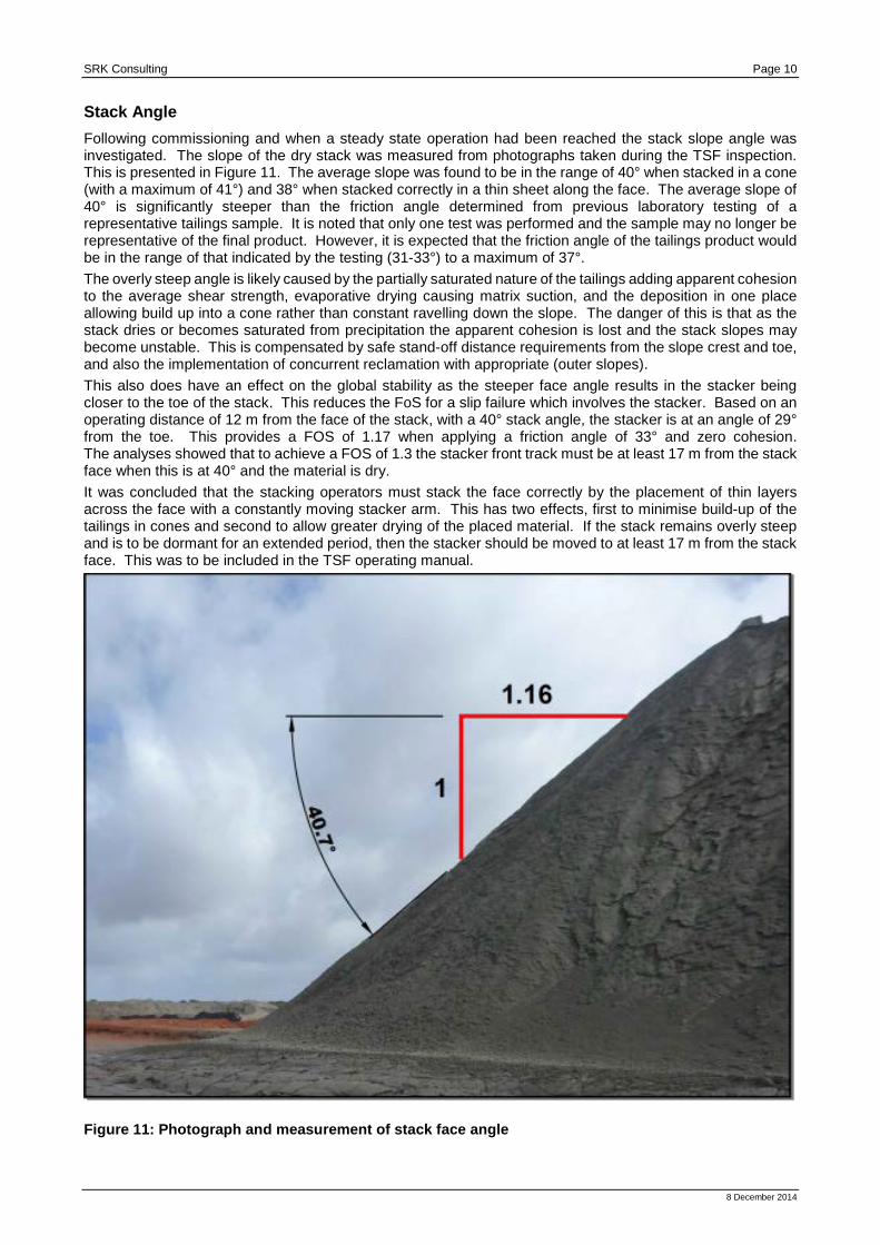
Stack Angle Following commissioning and when a steady state operation had been reached the stack slope angle was investigated. The slope of the dry stack was measured from photographs taken during the TSF inspection. This is presented in Figure 11. The average slope was found to be in the range of 40° when stacked in a cone (with a maximum of 41°) and 38° when stacked correctly in a thin sheet along the face. The average slope of 40° is significantly steeper than the friction angle determined from previous laboratory testing of a representative tailings sample. It is noted that only one test was performed and the sample may no longer be representative of the final product. However, it is expected that the friction angle of the tailings product would be in the range of that indicated by the testing (31-33°) to a maximum of 37°. The overly steep angle is likely caused by the partially saturated nature of the tailings adding apparent cohesion to the average shear strength, evaporative drying causing matrix suction, and the deposition in one place allowing build up into a cone rather than constant ravelling down the slope. The danger of this is that as the stack dries or becomes saturated from precipitation the apparent cohesion is lost and the stack slopes may become unstable. This is compensated by safe stand-off distance requirements from the slope crest and toe, and also the implementation of concurrent reclamation with appropriate (outer slopes). This also does have an effect on the global stability as the steeper face angle results in the stacker being closer to the toe of the stack. This reduces the FoS for a slip failure which involves the stacker. Based on an operating distance of 12 m from the face of the stack, with a 40° stack angle, the stacker is at an angle of 29° from the toe. This provides a FOS of 1.17 when applying a friction angle of 33° and zero cohesion. The analyses showed that to achieve a FOS of 1.3 the stacker front track must be at least 17 m from the stack face when this is at 40° and the material is dry. It was concluded that the stacking operators must stack the face correctly by the placement of thin layers across the face with a constantly moving stacker arm. This has two effects, first to minimise build-up of the tailings in cones and second to allow greater drying of the placed material. If the stack remains overly steep and is to be dormant for an extended period, then the stacker should be moved to at least 17 m from the stack face. This was to be included in the TSF operating manual.
Figure 11: Photograph and measurement of stack face angle
8 December 2014

SRK Consulting Page 11
Future test work Following on from the successful commissioning and initial operation of the Karara dry stack facility it is important to continue to update knowledge of the tailings material behaviour and properties in-situ. This is especially important prior to stacking lift 2 onto lift 1 and what the likely density regime of the initial stack is at that time. Cone penetrometer testing with pore pressure measurements (CPTu) of the first stack are proposed to determine in-situ density, shear strength and pore pressures/moisture distributions within the developed stack. This will be calibrated with test pitting and undisturbed sampling for laboratory testing. This probing and associated testing will be used to build a more realistic geotechnical profile, which in turn will help optimising the multi-lift design. This will include updated consolidation and storage capacity assessments, and stability analyses for the future intermediate and final configurations. Currently in-situ testing of the stack material on the active face is deemed unsafe and surface testing on the crest is considered unrepresentative. Conclusion The Karara TSF is a unique facility globally based on the combination of disposal methodology and rate. Additionally, there are no other dry stack facilities in Western Australia of any scale. The successful design, commissioning and operation of this facility demonstrates that this is a viable disposal strategy for other mines in similar conditions. The facility is operating as designed; commissioning of the facility provided some challenges which with some prior consideration can be overcome to remove any negative impact on the success of the dry stack facility as a whole. From the Karara commissioning experience these include measures to handle out of specification tailings and changes in stack configuration based on in-situ operating conditions.
8 December 2014