panels - Teknion · pame/p pawm paws pve 36" pe px px px pts px pts 06" px px ...

INSTRUCTION MANUAL
amperes ... the emerging preference
PUBLIC ADDRESS POWER AMPLIFIER
PX SERIES with built in AutoFault Sensor
PX2100 - 120 WattsPX2200 - 240 WattsPX2300 - 360 Watts
by - amperes electronics - www.ampereselectronics sdn bhd
POWER
CLIP
PROTECT
POWER
SIGNAL -10 dB
SIGNAL -40 dB PILOT TONE
AMP FAULT
ON
WITH AUTO FAULT SENSING
AUTO FAULT SENSING
amperes360 Watts
PX 2300S
PX2400 - 480 Watts

IMPORTANT SAFETY INSTRUCTIONS
The lightning flash symbol with arrowhead within an equilateral triangle is intended to alert the user to the presence of uninsulated "dangerous voltage" within the product's enclosure, that may be sufficient magnitude to be a risk of electric shock to person.
The exclamation mark within an equilateral triangle is intended to alert the user to the presence of important operating and
THIS UNIT MUST BE EARTHED
RISK OF ELECTRICAL SHOCK
WARNING !
DO NOT OPEN
WARNING - When using electric products, basic precautions should always be followed including the followings :
1. Read all the SAFE INSTRUCTIONS before using the product.2. This product must be earthed. If it should malfunction or breakdown, grounding provides a path of least resistance for electric current to reduce risk of electric shock.This product is equipped with a cord having an equipment grounding conductor and a grounding plug.The plug must be plugged into an appropriate outlet that is properly installed and earthed in accordance with all local codes and ordinance.
DANGER - Improper connection of the equipment-grounding connector can result in a risk of electric shock. Check with a qualified electrician or servicemen if you are in doubt as to whether the product is properly grounded. Do not modify the plug provided with the product, It it will not fit the outlet, have a proper outlet installed by a qualified electrician.
3. To reduce the risk of injury, close supervision is necessary when the product is used near children.4. Do not use this product near water, for example, near a bathtub, washbowl, kitchen sink, in a wet basement or near a swimming pool or the like.
5. This product should be located so that its location or position does not interfere with its proper ventillation. 6. This product should be located away from heat sources such as radiators, heat registers or other products that produce heat.
7. This product should be connected to a power supply only of the type described on the operating instructions or as marked on the product.8. This product may be equipped with a polarized line plug (one blade wider than the other). This is a safety feature. If you are unable to insert the plug into the outlet, contact an electrician to replace your obsolete outlet. Do not defeat the safety purpose of the plug.
9. The power supply cord of the product should be unplugged from the outlet when left unused for a long period of time. When unplugging the power supply cord, do not pull on the cord, but grasp it by the plug.10. Care should be taken so that object do not fall and liquid are not spilled into the enclosure through openings.
11. The product should be serviced by a qualified service personnel when :a. The power supply cord or the plug has been damaged or,
b. Objects has fallen, or liquid has been spilled into the product, or c. The product has been exposed to rain, or d. The product does not appear to operate normally or exhibits a marked change in performance, or e. The product has been dropped or the enclosure damaged.
12. Do not attempt to service the product beyond that described in the user-maintenance instructions. All other serving should be referred to qualified service personnel.
13. WARNING - do not place objects on the products' power cord or place it in a position where alone could trip over, walk on or roll anything over it. Do not allow the product to rest on or to be installed over power cords of any type. Improper installations of this type create the possibility of fire hazard and / or personal injury.
Page 2amperes electronics .... www.ampereselectronics.com

PARTS IDENTIFICATION
1. AC POWER SWITCH
Page 3amperes electronics .... www.ampereselectronics.com
PILOT TONE
AMP FAULT
ON
WITH AUTO FAULT SENSING
AUTO FAULT SENSING
amperes360 Watts
PX 2300S
POWER
CLIP
PROTECT
POWER
SIGNAL -10 dB
SIGNAL -40 dBOI
THIS EQUIPMENT REQUIRESADEQUATE VENTILATION
DO NOT BLOCK VENT
MAINS : 230V +/-10%AC 50 / 60HZ
BALANCED INPUT1V / 10K ?
GROUND LIFT
FLOAT FRAME
INPUT LINK
PRESS TO RESETBREAKER
OFFON
PILOT TONE
TO AX700
AC 5ADC 15A
PX
2 20 0
S
70V
(21
?)
1 00V
( 42
?)
CO
M
+24
V
SPEAKER OUTPUT
31V
(4?
)
+24
VDC INPUT
-24V
-24V
1 2 3 4
5 6 7
8 9 10 11 12 13
For switching mains ac supply and the corresponding LED shall lit. Mains LED shallnot lit whenever only DC back up supply is connected.
2. INDICATION LEDS Indication LEDs are : Power for incoming mains AC ; Protect LED to indicate that theunit is under protection mode when the temperature rises to a maximum level and theincoming signal is muted ; Clip to show that the incoming signal level is too high,typically above +4dB ; and Signal LEDs with two levels of -40dB and -10dB.
3. AFS INDICATORS This optional feature - Auto Fault Sensing can be monitored via the LEDs. ON Ledshows the the AFS is switched on ; Fault LED indicates that the unit is diagnosed asfaulty ; and the Pilot Tone LED shall lit at intervals to indicate that a 20kHz signal isbeing sent and received to check the condition of the unit. Whenever a Pilot Tonesignal is being sent, you shall notice that the signal level LED shall lit too. This isnormal.
5. DC SUPPLY Connect back up DC supply from batteries to the connectors using approriate cablesize. Check the rating of amplifier used and the corresponding cable load-size asundersize wire may cause cable overheat and eventually lead to fire.
6. SPEAKER OUTPUT Speaker terminals are available in 4 Ohm, 70 and 100V line outputs. Use only onetype of loading, ie. do not tap 70V output together with 100V line.
Total load should not exceed the capacity of the unit’s rating. The total speakerscombined should have impedance higher than stated in the corresponding outputterminals to avoid overloading.
Do not parallel two amplifiers in order to gain higher power rating as this may causeoverloading in the event that any one of them failed. The amplifier is not designed forparallel configurations.
4. FRONT VENT Ventillation holes for hot air which is blown out from the unit. Kindly ensure there issufficient clearance for heat dissipation in your installation.

Page 4amperes electronics .... www.ampereselectronics.com
PARTS IDENTIFICATION
7. CIRCUIT BREAKERS Manual resetable circuit breakers replaces the conventional fuse replacement, thuseasier maintenance. AC circuit breaker is for the mains whereas the DC is for theinternal DC voltage. To reset, simply press the button after any fault is removed.
8. VENT FAN External cool air is drawn to the unit’s heat sink via the dual speed fan. Whenever theheatsink temperature rises to above 45 deg celcius, the fan speed shall be automaticallyincreased.
9. FAULT CONTACT Whenever a faulty condition is detected, a dry contact shall be established. This port isconnected to Amperes AX700 to enable changeover to take place. This terminal is NOin normal condition. Close contact is establised too when the amplifier is switched off.
10. PT SWITCH The AFS feature can be switched off if required. Switching it off shall render the unit torun as any other normal amplifiers. Switching it ON shall be indicated by the front AFSLEDs.
11. GROUND LIFT
12. INPUT JACKS Incoming signal to the unit is via 3 pin XLR female socket and the adjacent male jack isconnected parallel for linkage to the next unit.
13. VOLUME KNOB Output volume is adjustable from -15dB to 0 dB.
NOTES
EARTH LOOP To avoid hum or noise to the output, the chassis earth and the electrical earth should beseparated by switching Ground Lift Switch ( 11 ) located at the rear panel.
MICROPHONE INPUT The signal input to the amplifier should be line level balanced type using XLR connector.Balanced signal generally cause less noise as compared to unbalanced type. Should anunbalanced signal is to be connected, short the pin 1 and 3 together at the XLR jack.Always remember to have either both ends of cable in balanced or unbalanced mode toavoid undesired results.
SPEAKER CONNECTIONspecified. Connecting speakers to 100V line shall have load equivalent to the sum of all therating of the speakers. Connecting the same loudspeakers to the 70V line shall onlyonsume half of the power. Thereby, twice the number of speakers of the said rating can beconnected to the 70V line terminal.
SPEAKER POLARITY Speakers with ‘+’ terminal should be connected to 100V line output. Sound clarity may becompromised when anti phase connections are made and is apparent when they areinstalled closed to each other.
The sliding switch allows separation of body earthing from signal common to preventhum
Total speakers connected to the output terminals should not exceed the unit’s rating

INTRODUCTION TO AUTO FAULT SENSING (AFS)
Page 5amperes electronics .... www.ampereselectronics.com
The above block diagrams shows a general method of monitoring the condition of the power amplifiers. Somemanufacturers may have different version of sensing but in general, the above concept applies.
Amperes PX series differs from the rest by only injecting Pilot Tone at intervals. This may cause a slight delay indetection of faults but in the long run, it may prevent premature amplifier failure. At cool intervals when pilot tone isnot injected, it means that no signal shall appear and thus no loading. Continuous PT injection may result in fasterdetection, however, it means continuous loading too. Although PT is not audible ( 20 KHz ), it does present at thespeaker ends and this represents pushing the unit to work all the time even though audio signal is not injected.
Amperes identifies the setback of continuous monitoring, thereby we employ a moderate method, ie. to inject atintervals. *** request for continuous monitoring can be fulfilled upon request.
AFS forms an integral part of Amperes PX series of amplifiers and thuseliminates the need to add external module for the monitoring of the powerpack. This does not only reduces the cabling complexities but also in overallcost of installation. Connecting the PX amplifiers to Amperes AX autochangeover panel shall then form an automatic amplifier monitoring systemwhich initiates a standby amplifier takeover, thus ensuring continuous anduninterrupted paging setup.
AUTO FAULT SENSING
ONAMP FAULTPILOT TONE
AFS indications located at front panel
AMPLIFICATIONSSIGNAL MIXING
PILOT TONE SIGNALGENERATION ANDSIGNAL RETURN
DETECTION /TRIGGERING CIRCUIT
AUDIO SIGNAL INPUTAND CONVERSION
CIRCUIT
AUDIO SIGNAL FROMMIXER PRE AMPLIFIEROR OTHER LINE INPUT
(BALANCED)
DRY CONTACTPROVISION ( NO)FOR CONNECTION TOAMPERES AX700
70 / 100V LINEOUTPUTS TO AX700ZONE SELECTORS /SPEAKERS / ETC
PILOT TONE DETECTION
DRY CONTACT ( FAULT - CLOSE CONTACT)
PILOT TONE
AUDIO
PILOT TONEAND AUDIOSIGNAL
WITHIN AMPLIFIER UNIT
OUTPUT
Block diagram showing theconcept of AFS functionemployed by PX seriesamplifiers.
OFFON
PILOT TONE
TO AX700
AFS section at rear panel
The standard feature available in PX series can beswitched off if required, thereby rendering the unit tobe operating like any other type of normal amplifiers.
This can be done by sliding the switch to OFFposition. In this condition, the front section AFS LEDindicators shall be turned off as well.
For a complete setup, link PX amplifiers to AmperesAX700 with the contact port connected to the correspond-ing triggering terminal at the latter.
The quantity of AX700 shall be according to the number ofamplifiers available in the system. Each AX700 can caterfor 6 ut duty and 1 standby amplifiers. Cascade AX700 ifnecessary.

Page 6amperes electronics .... www.ampereselectronics.com
BLOCK DIAGRAM
100V70 V25 VCOMMON
OUTPUTTERMINALS
DRY CONTACT TOAMPERES AX700
TRIGGERING TERMINALS
AUDIOINPUTJACK
PARALLELOUTPUT TO NEXT UNIT
INCOMINGAC POWER
SUPPLY
BACK UP BATTERY INPUT
( 24V DC )
28V DC OUTPUT TO INTERNAL
CIRCUITRIES
AFS LED indicators
The above block diagram is illustrative only and does not represent the actual or detailed construction schematic. Detailed circuit shall be available only to our authorised service centres.
LED indicators
AFS Pilot Tone generation and PT feedback detection circuis
PT on/off switch
Level adjust
Ground lift switch
Signal conversion
Thermistor - Q point - temperature
Thermistor - fan speed / thermal cut offCut off temp - 85C
Dual speed fanThreshold - 45C
Mixing and Protectioncircuits
Amp circuit
Step-uptransformer
Bridge rectifier
Mains step down transformer
DC blocking rectifier
AC circuitbreaker
DC circuit breaker
Mainsswitch
INSTALLATION
Page 7amperes electronics .... www.ampereselectronics.com
PILOT TONE
AMP FAULT
ON
WITH AUTO FAULT SENSING
AUTO FAULT SENSING
amperes360 Watts
PX 2300S
POWER
CLIP
PROTECT
POWER
SIGNAL -10 dB
SIGNAL -40 dBOI
PILOT TONE
AMP FAULT
ON
AUTO FAULT SENSING
OI
PX 2100 amperes
SIGNAL -40 dB
SIGNAL -10 dB
POWER
PROTECT
CLIP
2100PX120 Watts
POWER
HOT AIR
HOT AIR
HOT AIR
HOT AIR
HOT AIR
HOT AIR
AIR INTAKE
AIR INTAKE
PX2200 / 2300
PX2100
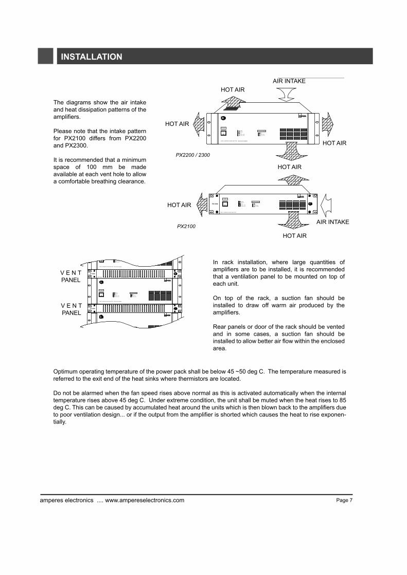
The diagrams show the air intakeand heat dissipation patterns of theamplifiers.
Please note that the intake patternfor PX2100 differs from PX2200and PX2300.
It is recommended that a minimumspace of 100 mm be madeavailable at each vent hole to allowa comfortable breathing clearance.
amperes
amperes
PILOT TONE
AMP FAULT
ON
WITH AUTO FAULT SENSING
AUTO FAULT SENSING
amperes360 Watts
PX 2300S
POWER
CLIP
PROTECT
POWER
SIGNAL -10 dB
SIGNAL -40 dBOI
WITH AUTO FAULT SENSING
CLIP
SIGNAL -10 dB
SIGNAL -40 dBO
amperes360 Watts
PX 2300S
V E N TPANEL
V E N TPANEL
In rack installation, where large quantities ofamplifiers are to be installed, it is recommendedthat a ventilation panel to be mounted on top ofeach unit.
On top of the rack, a suction fan should beinstalled to draw off warm air produced by theamplifiers.
Rear panels or door of the rack should be ventedand in some cases, a suction fan should beinstalled to allow better air flow within the enclosedarea.
Optimum operating temperature of the power pack shall be below 45 ~50 deg C. The temperature measured isreferred to the exit end of the heat sinks where thermistors are located.
Do not be alarmed when the fan speed rises above normal as this is activated automatically when the internaltemperature rises above 45 deg C. Under extreme condition, the unit shall be muted when the heat rises to 85 deg C. This can be caused by accumulated heat around the units which is then blown back to the amplifiers dueto poor ventilation design... or if the output from the amplifier is shorted which causes the heat to rise exponen-tially.
Page 8amperes electronics .... www.ampereselectronics.com
SCHEMATIC - NORMAL PAGING SETUP
CE
ILIN
GS
PE
AK
ER
S
CO
LUM
N /
BO
X S
PK
S
HO
RN
SP
EA
KE
RS
VO
L.C
ON
TRO
LS
AM
P.M
ON
ITO
R P
AN
EL
ZS51
21 /
5601
ZON
E S
ELE
CTO
R
SP
EA
KE
R L
INE
MO
NIT
OR
ING
AM
PE
RE
S A
X70
0C
HA
NG
EO
VE
R P
AN
EL
DU
TY A
MP
DU
TY A
MP
STA
ND
BY
AM
P
EM
ER
GE
NC
YPA
GIN
G M
ICP
RE
-AM
PM
IXE
RB
GM
PLA
YE
RS PA
GIN
G
MIC
PAG
ING
MIC
w Z
ON
E
zone
con
trol c
able
all c
all
line
out
100V
trigg
er
trigg
er
trigg
er
100V
100V
100V
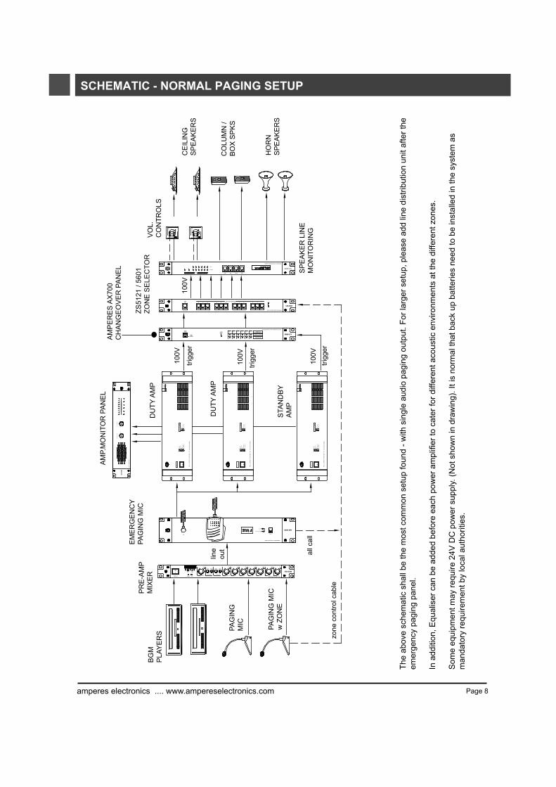
The
abov
e sc
hem
atic
sha
ll be
the
mos
t com
mon
set
up fo
und
- with
sin
gle
audi
o pa
ging
out
put.
For l
arge
r set
up, p
leas
e ad
d lin
e di
strib
utio
n un
it af
ter t
he
emer
genc
y pa
ging
pan
el.
In a
dditi
on, E
qual
iser
can
be
adde
d be
fore
eac
h po
wer
am
plifi
er to
cat
er fo
r diff
eren
t aco
ustic
env
ironm
ents
at t
he d
iffer
ent z
ones
.
Som
e eq
uipm
ent m
ay re
quire
24V
DC
pow
er s
uppl
y. (N
ot s
how
n in
dra
win
g). I
t is
norm
al th
at b
ack
up b
atte
ries
need
to b
e in
stal
led
in th
e sy
stem
as
man
dato
ry re
quire
men
t by
loca
l aut
horit
ies.

SCHEMATIC - UNINTERRUPTED PAGING SETUP
Page 9amperes electronics .... www.ampereselectronics.com
CE
ILIN
GS
PE
AK
ER
S
CO
LUM
N/
BO
XS
PE
AK
ER
S
HO
RN
SP
EA
KE
RS
VO
L.C
ON
TRO
LS
SP
K L
INE
MO
NIT
OR
ZS56
02S
ELE
CTO
R
AM
PE
RE
SA
X70
0A
MP.
CH
AN
GE
OV
ER
AM
P.M
ON
ITO
R
PAG
ING
AM
P
BG
MA
MP
STA
ND
BY
AM
P
STA
ND
BY
AM
PC
HA
NG
EO
VE
R F
OR
BG
MA
MP
s
CH
AN
GE
OV
ER
FO
RPA
GIN
GA
MP
sE
ME
RG
EN
CY
PAG
ING
MIX
ER
PAG
ING
MIC PA
GIN
G M
ICw
ZO
NE
BG
MP
LAY
ER
S
24V
O/R
100V
100V
Lin
e
BG
Min
put
PAG
ING
inpu
t
Line
Out
BG
M o
ut
zone
con
trol c
able
ALL
CA
LLtri
gger
ing
100V
Line
The
abov
esc
hem
atic
illus
trate
san
unin
terr
upte
dpa
ging
setu
pse
rvin
gsi
xzo
nes.
2se
tsof
ampl
ifir
;B
GM
and
Pag
ing
are
requ
ired,
each
with
itsow
nst
andb
yam
plifi
erch
ange
over
.In
man
yca
ses,
this
may
notb
eec
onom
ical
and
itis
norm
alto
have
BG
M p
ower
pac
ks w
ithou
t a s
tand
by u
nit.
Ther
efor
e, y
ou m
ay o
nly
need
one
AX
700
in th
e sy
stem
.
For l
arge
set
up w
ith a
mpl
ifier
s ex
ceed
ing
6 un
its, i
t is
advi
sabl
e to
add
line
dis
tribu
tor a
fter t
he e
mer
genc
y pa
ging
pan
el a
s to
om
uch
sign
al p
aral
lelin
g m
ay c
ause
und
esira
ble
dist
ortio
n to
the
outp
ut.

Page 10amperes electronics .... www.ampereselectronics.com
CONNECTIONSTH
I SE
QU
I PM
EN
TR
EQU
IRES
AD
EQ
UA
TEV
EN
TILA
TIO
N
DO
NO
TB
LOC
KV
EN
T
MA I
NS
:230
V+ /
-10 %
AC
50/6
0HZ
BA
LAN
CE
DIN
PU
T1V
/10K
?
GR
OU
ND
LIFT
FLO
ATFR
AM
E
INP
UT
L IN
K
PR
ES
STO
RES
ETB
RE
AKE
R
OFF
ON
PI L
OT
T ON
E
TOA
X70
0
AC
5AD
C15
A
PX2200S
70V(21?)
100V(42?)
COM
+24V
SPE
AK
ER
OU
T PU
T
31V(4?)
+24V
DC
INPU
T
-24V
-24V
THIS
EQ
UI P
ME
NT
REQ
UIR
ESA
DE
QU
ATE
VE
NT I
LATI
ON
DO
NO
TB
LOC
KV
EN
T
MA I
NS
:23 0
V+ /
-10 %
AC
50/6
0HZ
BA
LAN
CE
DIN
PU
T1 V
/10K
?
GR
OU
ND
LIF T
FLO
A TFR
AM
E
INP
UT
L IN
K
PR
ES
STO
RES
ETB
RE
AKE
R
OFF
ON
PIL
OT
TON
E
TOA
X7 0
0
AC
5AD
C15
A
PX2200S
70V(21?)
100V(42?)
COM
+24V
SPE
AK
ER
OU
T PU
T
31V(4?)
+24V
DC
INPU
T
-24V
-24V
THIS
EQ
UI P
ME
NT
REQ
UI R
ESA
DE
QU
ATE
VE
NTI
LATI
ON
DO
NO
TB
L OC
KV
EN
T
MAI
NS
:230
V+ /
-10 %
AC
5 0/6
0HZ
BA
LAN
CE
DIN
PU
T1 V
/10K
?
GR
OU
ND
LIFT
F LO
A TFR
AM
E
I NP
UT
LIN
K
PR
ES
STO
RES
E TB
RE
AKE
R
OFF
ON
PIL
OT
TON
E
T OA
X70
0
AC
5AD
C15
A
PX2200S
70V(21?)
100V(42?)
COM
+24V
SPE
AK
ER
OU
T PU
T
31V(4?)
+24V
DC
INPU
T
-24V
-24V
THIS
EQ
UIP
ME
NT
REQ
UI R
ESA
DE
QU
AT E
VE
NTI
LATI
ON
DO
NO
TB
LOC
KV
EN
T
MAI
NS
: 230
V+/
-10%
AC
5 0/ 6
0HZ
BA
LAN
CE
DIN
PU
T1V
/10 K
?
GR
OU
ND
L IFT
FLO
ATF R
AM
E
INP
UT
LIN
K
PR
ES
STO
RES
E TB
RE
AKE
R
OFF
ON
PIL
OT
TON
E
TOA
X70
0
AC
5 AD
C15
A
PX2200S
70V(21?)
100V(42?)
COM
+24V
SPE
AKE
RO
UT P
UT
31V(4?)
+24V
DC
INPU
T
-24V
-24V
TO S
PE
AK
ER
ZO
NE
S
ELE
CTO
R -
-- L
INE
S
UR
VE
LLA
NC
E -
- VO
LUM
E
CO
NTR
OLS
---
SP
EA
KE
RS
INPUT SOURCES ( MICSAND BGM SOURCES )
DU
TYA
MP
1
DU
TYA
MP
2
DU
TYA
MP
6
STA
ND
BY
AM
P
MIX
ER
PR
E-A
MP
AM
PE
RE
SA
X70
0A
UTO
AM
P C
HA
NG
EO
VE
RPA
NE
L
Trig
gerin
gte
rmin
als
Sta
ndby
Am
pin
put
Dut
yA
mps
Inpu
ts
com
stan
dby
trigg
er
duty
am
p 1
trigg
er
duty
am
p 6
trigg
er
The
abov
eex
ampl
esh
ows
asy
stem
usin
g6
duty
ampl
ifier
sw
ith1
stan
dby
with
dire
ctpa
ging
setu
p. i
e.at
any
one
time,
eith
era
pagi
ngor
BG
Mis
allo
wed
tobe
broa
dcas
ted
toal
lzon
es. C
asca
deA
X70
0if
nece
ssar
yw
hen
the
num
bero
fdut
yam
plifi
ers
exce
eds
6un
itw
ith o
nly
1 st
andb
y po
wer
pac
k.
Oth
erad
ditio
nale
quip
men
tsm
aybe
adde
dbu
tnot
show
nsu
chas
back
upba
tterie
s,am
plifi
erm
onito
rpan
el,s
peak
erzo
nese
lect
ors,
volu
me
cont
rolle
rs, e
tc.
MIN
1.5
mm
cab
le
24 a
wg
cabl
e

www.ampereselectronics.comPage 11
TECHNICAL SPECIFICATIONS
ELECTRICALPower requirement
Rated output
Output impedance / line
Power consumption
Input sensitivityInput gain controlInput connectionsFrequency ResponseSignal / Noise ratio (at 1 KHz, 0 dB)
Protections
IndicatorsCooling system
AUTO FAULT DETECTIONDetection intervalDetection responseDetection methodFailure recovery timeFailure output
PHYSICALDimensions (H x W x D mm)
WeightColour
AC 230/240V : 50/60 Hz24V DC : PX2100S - 6A ; PX2200S - 19A
PX2300S - 29A ; PX2400S - 35APX2100S : 120W 100V linePX2200S : 240W 100V linePX2300S : 360W 100V linePX2400S : 480W 100V line
PX2100S : 4 ohm (22V) / 42 ohm (70V) / 83 ohm (100V)PX2200S : 4 ohm (31V) / 21 ohm (70V) / 42 ohm (100V)PX2300S : 4 ohm (38V) / 13.6 ohm (70V) / 27.8 ohm (100V)PX2400S : 4 ohm (44V) / 10 ohm (70V) / 21 ohm (100V)PX2100S : No input - 30VA, Rated output - 230 VAPX2200S : No input - 38VA, Rated output - 720 VAPX2300S : No input - 40VA, Rated output - 1080 VA
1V / 10 K Ohm-15 dB to 0 dBXLR balanced input80 - 17 kHz 0/-5 dB> 80 dB
Thermal overload muting /AC and DC manual reset circuit breaker / Momentary short circuitInput Mains ; Clip ; Protect mode ; Input signalFan forced cooling with dual speed thermal controlled presets
10 seconds15 - 25 secondsInternal pilot tone at 20 kHz20 seconds maxDry contact ( NO at 3A
rating )
PX2100S (88x482x300) mm PX2200S / PX2300S / PX2400S (133x482x300) mm
PX2100S - 11.6kg : PX2200S - 21kg : PX2300S - 24.2kg : PX2400S - 29kgBlack ; powder epoxy coated
Due to our continuous product improvement policy, we reserve the rights to change the above specifications, features and artwork without prior notice.
While every care was taken to ensure the data produced in this manual is correct at time of printing, we apologize if there were to be any error that may have been unintentionally presented or omitted.
PX2400S : No input - 40VA, Rated output - 1180 VA
Updated OCT 2007
Amperes Electronics Sdn BhdCo Reg : 509025-X
www.ampereselectronics.com
Only Amperes Electronics Service Centres are allowed to make warranty repairs : a list of Amperes ElectronicsService Centres may be asked for by the purchaser or send directly to Amperes Electronics Sdn Bhd or itsauthorized master distributor, Amperes Global Marketing. This warranty is not valid if repairs are performed byunauthorized personnel or service centres.
This warranty covers only repairs and replacement of defective parts ; cost and risks of transportation as well asremoval and installation of the product from the main system are for the account of the purchaser. This warrantyshall not extend to the replacement of the unit.
This warranty does not cover damages caused by misuse, neglect, accident of the product as well as using theproduct with power supply voltage other than shown on the product, or any other power supply source / adaptornot recommended by the manufacturer.
This warranty does not cover damages caused by fire, earthquakes, floods. lightning and every cause not directlyrelated to the unit.
This warranty does not include any indemnity in favor of the purchaser or the dealer for the period out of use ofthe unit; moreover the warranty does not cover any damages which may be caused to people and things whenusing the product.
This warranty certificate is valid only for the described product, and is not valid if modifications are made on thiscertificate or on the identification label applied on the product.
This warranty covers all the material and manufacturing defects and is valid for a period of 12 months from thedate of purchase or for a longer period in countries where this is stated by a national law. In this case, theextension is valid only in the country where the product is purchased.
Amperes Electronics Sdn Bhd is not obliged to modify previously manufactured products under warranty if thedesign changes or improvements are made.
WARRANTY CONDITIONS
DISCLAIMER
Information contained in this manual is subject to change without prior notice and does not represent acommitment on the part of the vendor. AMPERES ELECTRONICS SDN BHD shall not be liable for any loss ordamages whatsoever arising from the use of information or any error contained in this manual.
It is recommended that all services and repairs on this product be carried out by AMPERES ELECTRONICS SDNBHD or its authorized service agents.
AMPERES series must only be used for the purpose they were intended by the manufacturer and in conjunctionwith this operating manual.
AMPERES ELECTRONICS SDN BHD cannot accept any liability whatsoever for any loss or damages caused byservice, maintenance or repair by unauthorized personnel, or by use other than that intended by themanufacturer.
It is understood that the purchaser accepted and had read through the above terms and conditions of warrantyand disclaimer upon unpacking and tested the product.