Packeteer Packet Shaper (3621)
38
Packeteer Device Management Supports Management Module SM-PKT1000 Titlepae
Transcript of Packeteer Packet Shaper (3621)
Packeteer
Device Management
Supports Management Module SM-PKT1000
Titlepae
D e v i c e M a n a g e m e n t Page 2 P a c k e t e e r
Copyright NoticeDocument 3621. Copyright © 2002-present Aprisma Management Technologies, Inc. All rights reserved worldwide. Use, duplication, or disclosure by the United States government is subject to the restrictions set forth in DFARS 252.227-7013(c)(1)(ii) and FAR 52.227-19.
Liability DisclaimerAprisma Management Technologies, Inc. (“Aprisma”) reserves the right to make changes in specifications and other information contained in this document without prior notice. In all cases, the reader should contact Aprisma to inquire if any changes have been made.The hardware, firmware, or software described in this manual is subject to change without notice.IN NO EVENT SHALL APRISMA, ITS EMPLOYEES, OFFICERS, DIRECTORS, AGENTS, OR AFFILIATES BE LIABLE FOR ANY INCIDENTAL, INDIRECT, SPECIAL, OR CONSEQUENTIAL DAMAGES WHATSOEVER (INCLUDING BUT NOT LIMITED TO LOST PROFITS) ARISING OUT OF OR RELATED TO THIS MANUAL OR THE INFORMATION CONTAINED IN IT, EVEN IF APRISMA HAS BEEN ADVISED OF, HAS KNOWN, OR SHOULD HAVE KNOWN, THE POSSIBILITY OF SUCH DAMAGES.Trademark, Service Mark, and Logo InformationSPECTRUM, IMT, and the SPECTRUM IMT/VNM logo are registered trademarks of Aprisma Management Technologies, Inc., or its affiliates. APRISMA, APRISMA MANAGEMENT TECHNOLOGIES, the APRISMA MANAGEMENT TECHNOLOGIES logo, MANAGE WHAT MATTERS, DCM, VNM, SpectroGRAPH, SpectroSERVER, Inductive Modeling Technology, Device Communications Manager, SPECTRUM Security Manager, and Virtual Network Machine are unregistered trademarks of Aprisma Management Technologies, Inc., or its affiliates. For a complete list of Aprisma trademarks, service marks, and trade names, go tohttp://www.aprisma.com/manuals/trademark-list.htm.All referenced trademarks, service marks, and trade names identified in this document, whether registered or unregistered, are the intellectual property of their respective owners. No rights are granted by Aprisma Management Technologies, Inc., to use such marks, whether by implication, estoppel, or otherwise. If you have comments or concerns
about trademark or copyright references, please send an e-mail to [email protected]; we will do our best to help.Restricted Rights Notice(Applicable to licenses to the United States government only.)
This software and/or user documentation is/are provided with RESTRICTED AND LIMITED RIGHTS. Use, duplication, or disclosure by the government is subject to restrictions as set forth in FAR 52.227-14 (June 1987) Alternate III(g)(3) (June 1987), FAR 52.227-19 (June 1987), or DFARS 52.227-7013(c)(1)(ii) (June 1988), and/or in similar or successor clauses in the FAR or DFARS, or in the DOD or NASA FAR Supplement, as applicable. Contractor/manufacturer is Aprisma Management Technologies, Inc. In the event the government seeks to obtain the software pursuant to standard commercial practice, this software agreement, instead of the noted regulatory clauses, shall control the terms of the government's license.
Virus DisclaimerAprisma makes no representations or warranties to the effect that the licensed software is virus-free.Aprisma has tested its software with current virus-checking technologies. However, because no antivirus system is 100 percent effective, we strongly recommend that you write-protect the licensed software and verify (with an antivirus system in which you have confidence) that the licensed software, prior to installation, is virus-free.Contact InformationAprisma Management Technologies, Inc.273 Corporate DrivePortsmouth, NH 03801Phone: 603-334-2100U.S. toll-free: 877-468-1448Web site: http://www.aprisma.com
D e v i c e M a n a g e m e n t Page 3 P a c k e t e e r
ContentsINTRODUCTION 5
Purpose and Scope ........................................................5Required Reading ...........................................................5Supported Devices..........................................................6The SPECTRUM Model ..................................................7
TASKS 9
DEVICE VIEW 10
Interface Icons ..............................................................11Interface Icon Subviews Menu......................................12Interface Status View ....................................................12Secondary Address Panel ............................................13
DEVICE TOPOLOGY VIEW 14
APPLICATION VIEWS 15
Supported Applications .................................................16Common Applications................................................16Device-Specific MIBs.................................................17
Packeteer Packet Shaper Common Application ...........18Packeteer PSCommonApp Configuration View ........18
Trap Destination Table...........................................18PSAlarm Configuration View..................................19
Response Time Management Configuration View ....20Threshold Config ................................................20
Total Delay Bucket Conf..................................... 20Network and Server Delay Bucket Config View..... 21
N/W Delay Bucket Limit...................................... 21Server Delay Bucket Lim.................................... 22
Worst Server and Client Configuration View ......... 22Server Table....................................................... 22Client Table ........................................................22
PERFORMANCE VIEWS 23
Packeteer PSCommonApp Performance View............. 24Link Table 1............................................................... 24Link Table 2............................................................... 25Link Table 3............................................................... 25
Partition Table........................................................26Partition Table 1 ................................................. 26Partition Table 2 ................................................. 26Partition Table 3 ................................................. 27Partition Table 4 ................................................. 27
Class Table ............................................................ 28Class Table 1 ..................................................... 28Class Table 2 ..................................................... 28Class Table 3 ..................................................... 29Class Table 4 ..................................................... 29
Packeteer PSRTMApp Performance View ................... 30Response Time Management Table ......................... 30Response Time Management Table 2 ...................... 32
C o n t e n t s C o n t e n t s
D e v i c e M a n a g e m e n t Page 4 P a c k e t e e r
CONFIGURATION VIEWS 34
Device Configuration View............................................34
MODEL INFORMATION VIEW 36
INDEX 37
D e v i c e M a n a g e m e n t Page 5 P a c k e t e e r
Introduction
This section introduces the SPECTRUM Device Management documentation for Packeteer devices.
This introduction contains the following topics:
• Purpose and Scope
• Required Reading
• Supported Devices (Page 6)
• The SPECTRUM Model (Page 7)
Purpose and ScopeUse this documentation as a guide for managing Packeteer Inc., devices with the SPECTRUM management module SM-PKT1000. The documentation describes the icons, menus, and views that enable you to remotely monitor, configure, and troubleshoot Packeteer PacketShaper and Packeteer AppVantage devices through software models in your SPECTRUM database.
Only information specific to the supported management module is included under this documentation topic. For general information
about device management using SPECTRUM and for explanations of basic SPECTRUM functionality and navigation techniques, refer to the topics listed under Required Reading.
Required ReadingTo use this documentation effectively, you must be familiar with the information covered by the other SPECTRUM online documentation topics listed below.
• Getting Started with SPECTRUM for Operators
• Getting Started with SPECTRUM for Administrators
• How To Manage Your Network with SPECTRUM
• SPECTRUM Views
• SPECTRUM Menus
• SPECTRUM Icons
• Management Module Software Release Notice
I n t r o d u c t i o n S u p p o r t e d D e v i c e s
D e v i c e M a n a g e m e n t Page 6 P a c k e t e e r
Supported Devices The SPECTRUM management module SM-PKT1000 currently allows you to model four different types of Packeteer Packetshaper devices and four types of AppVantage devices as described below.
Packeteer PacketShaper 1500. An entry-level platform designed to manage applica-tion performance for branch offices and remote sites with WAN links up to T1/E1. This device supersedes the 1000.
Packeteer PacketShaper 2500. Modular, mid-range platform designed to manage application performance for WAN links that are multiple T1s/E1s, one T1/E1, or frac-tional T3/E3. Expansion slots are available for future capacity, connectivity, and capabil-ity upgrades. This device supersedes the 2000.
Packeteer PacketShaper 4500. Modular, high-availability platform designed to man-age application performance at large sites with up to T3/E3 WAN links. Expansion slots are available for future capacity, connectivity, and capability upgrades. This device super-sedes the 4000.
PacketShaper-6500. A faster version of the PacketShaper.
AppVantage ASM-30. Designed for connect-ing remote customer branches at WAN speed Mbps.
AppVantage ASM-50. Mid-range platform designed for WAN speeds up to 10 Mbps.
AppVantage ASM-70. High-performance plat-form designed for ASP and customer datace WAN speeds up to 45 Mbps.
AppVantage ASM-90. A higher performance version of the AppVantage PacketShaper device.
I n t r o d u c t i o n T h e S P E C T R U M M o d e l
D e v i c e M a n a g e m e n t Page 7 P a c k e t e e r
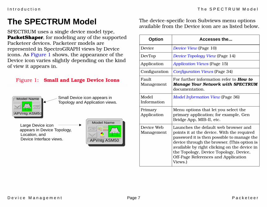
The SPECTRUM ModelSPECTRUM uses a single device model type, PacketShaper, for modeling any of the supported Packeteer devices. Packeteer models are represented in SpectroGRAPH views by Device icons. As Figure 1 shows, the appearance of the Device icon varies slightly depending on the kind of view it appears in.
Figure 1: Small and Large Device Icons
The device-specific Icon Subviews menu options available from the Device icon are as listed below.
Large Device iconModel Name
Model Name
APVntg ASM50
Small Device icon appears in
APVntg ASM50
Topology and Application views.
appears in Device Topology,Location, andDevice Interface views.
Option Accesses the...
Device Device View (Page 10)
DevTop Device Topology View (Page 14)
Application Application Views (Page 15)
Configuration Configuration Views (Page 34)
Fault Management
For further information refer to How to Manage Your Network with SPECTRUM documentation.
Model Information
Model Information View (Page 36)
Primary Application
Menu options that let you select the primary application; for example, Gen Bridge App, MIB-II, etc.
Device Web Management
Launches the default web browser and points it at the device. With the required password it is then possible to manage the device through the browser. (This option is available by right clicking on the device in the Topology, Device Topology, Device, Off-Page References and Application Views.)
I n t r o d u c t i o n T h e S P E C T R U M M o d e l
D e v i c e M a n a g e m e n t Page 8 P a c k e t e e r
The rest of the documentation for this management module is organized according to view type, as follows.
• Device View (Page 10)• Device Topology View (Page 14)• Application Views (Page 15)• Performance Views (Page 23)• Configuration Views (Page 34)• Model Information View (Page 36)
D e v i c e M a n a g e m e n t Page 9 P a c k e t e e r
Tasks
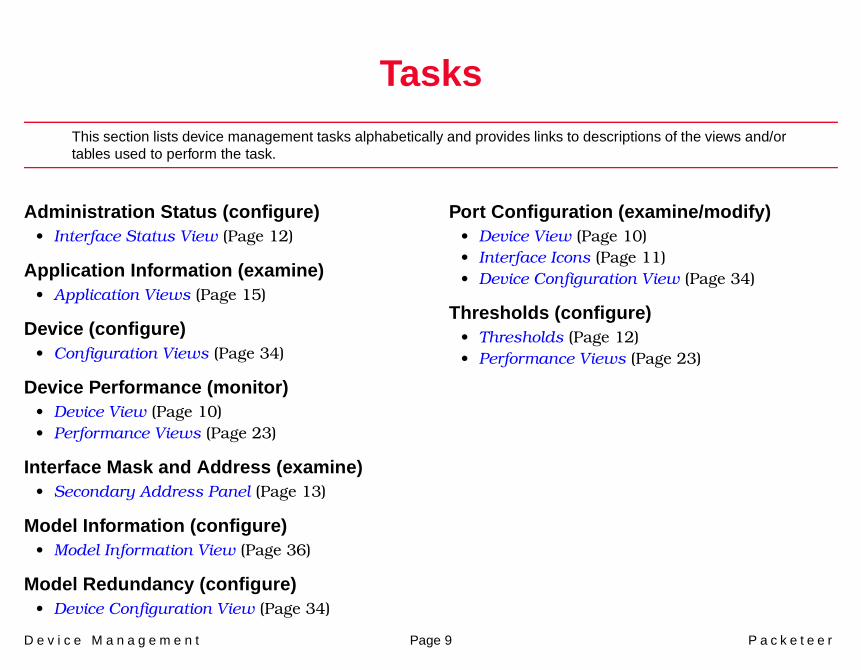
This section lists device management tasks alphabetically and provides links to descriptions of the views and/or tables used to perform the task.
Administration Status (configure)• Interface Status View (Page 12)
Application Information (examine)• Application Views (Page 15)
Device (configure)• Configuration Views (Page 34)
Device Performance (monitor)• Device View (Page 10)• Performance Views (Page 23)
Interface Mask and Address (examine)• Secondary Address Panel (Page 13)
Model Information (configure)• Model Information View (Page 36)
Model Redundancy (configure)• Device Configuration View (Page 34)
Port Configuration (examine/modify)• Device View (Page 10)• Interface Icons (Page 11)• Device Configuration View (Page 34)
Thresholds (configure)• Thresholds (Page 12)• Performance Views (Page 23)
D e v i c e M a n a g e m e n t Page 10 P a c k e t e e r
Device View
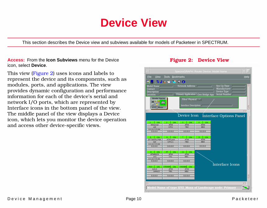
This section describes the Device view and subviews available for models of Packeteer in SPECTRUM.
Access: From the Icon Subviews menu for the Device icon, select Device.
This view (Figure 2) uses icons and labels to represent the device and its components, such as modules, ports, and applications. The view provides dynamic configuration and performance information for each of the device’s serial and network I/O ports, which are represented by Interface icons in the bottom panel of the view. The middle panel of the view displays a Device icon, which lets you monitor the device operation and access other device-specific views.
Figure 2: Device View
SpectroGRAPH: Router Device: Model Name
File View HelpTools
Model NameContactDescriptionLocation
Sys Up TimeManufacturerDevice TypeSerial Number
Network Address
Interface Description
Filter Physical
Interface Options PanelDevice Icon
XYZ_Mxxx
Model Name
1Ethernet
0:0:1D:F:FD:B6
ei0
0.0.0.0
ON
5SFTWARLPBK
0:0:1D:F:FD:B6lo0
0.0.0.0
ON
9ATM8023
0:0:1D:F:FD:B6
zn1
0.0.0.0
ON
512AAL5
UAAL5
0.0.0.0
ON
2ATMCPU
0.0.0.0
ON
6ATM portCPU.1
0.0.0.0
ON
ATM7A1
0.0.0.0
ON
ATM7B1
0.0.0.0
ON
ATM7B2
0.0.0.0
ON
ATM7B3
0.0.0.0
ON
ATM8B1
0.0.0.0
ON
ATM8B2
0.0.0.0
ON
ATM8B3
0.0.0.0
ON
ATM8B4
0.0.0.0
ON
10
2783905 2783909
11
7
3 4
8
Interface Icons
Bookmarks
Model Name of type XYZ_Mxxx of Landscape node: Primary
Primary Application Gen Bridge App
D e v i c e V i e w I n t e r f a c e I c o n s
D e v i c e M a n a g e m e n t Page 11 P a c k e t e e r
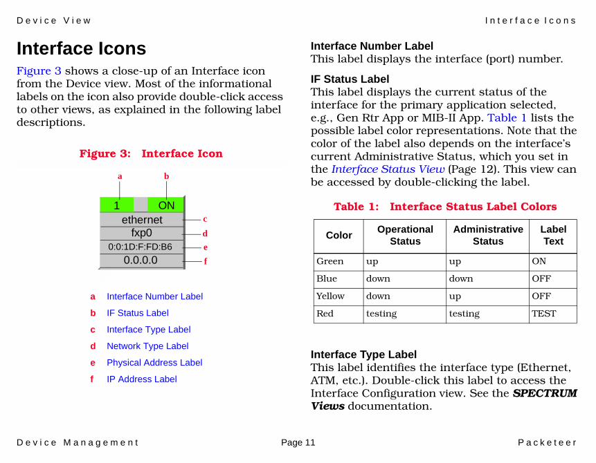
Interface IconsFigure 3 shows a close-up of an Interface icon from the Device view. Most of the informational labels on the icon also provide double-click access to other views, as explained in the following label descriptions.
Figure 3: Interface Icon
Interface Number LabelThis label displays the interface (port) number.
IF Status LabelThis label displays the current status of the interface for the primary application selected, e.g., Gen Rtr App or MIB-II App. Table 1 lists the possible label color representations. Note that the color of the label also depends on the interface’s current Administrative Status, which you set in the Interface Status View (Page 12). This view can be accessed by double-clicking the label.
Interface Type LabelThis label identifies the interface type (Ethernet, ATM, etc.). Double-click this label to access the Interface Configuration view. See the SPECTRUM Views documentation.
c
f
b
1ethernet
0:0:1D:F:FD:B6
a
a Interface Number Label
b IF Status Label
c Interface Type Label
d Network Type Label
e Physical Address Label
f IP Address Label
fxp0
0.0.0.0
d
e
ON Table 1: Interface Status Label Colors
Color OperationalStatus
AdministrativeStatus
LabelText
Green up up ON
Blue down down OFF
Yellow down up OFF
Red testing testing TEST
D e v i c e V i e w I n t e r f a c e I c o n S u b v i e w s M e n u
D e v i c e M a n a g e m e n t Page 12 P a c k e t e e r
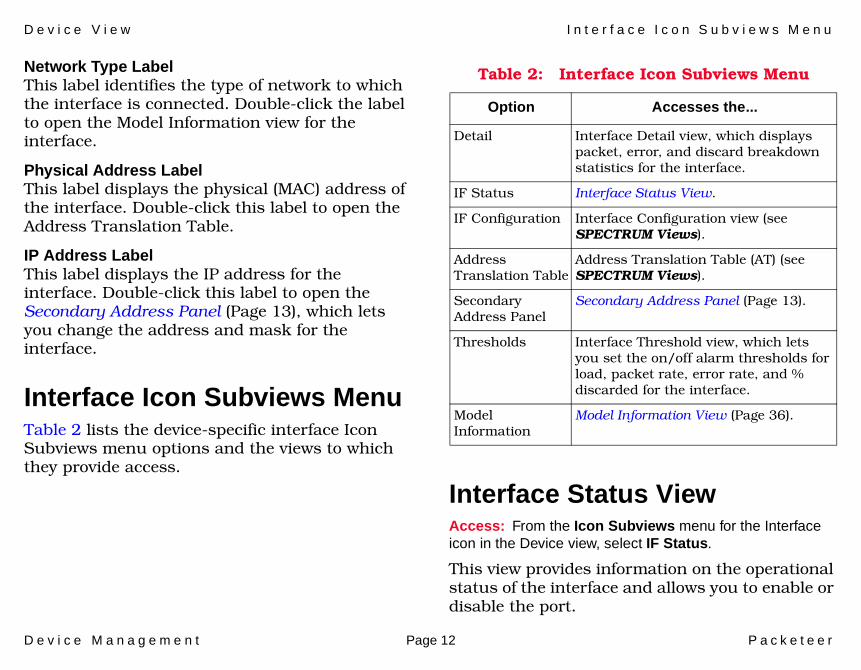
Network Type LabelThis label identifies the type of network to which the interface is connected. Double-click the label to open the Model Information view for the interface.
Physical Address LabelThis label displays the physical (MAC) address of the interface. Double-click this label to open the Address Translation Table.
IP Address LabelThis label displays the IP address for the interface. Double-click this label to open the Secondary Address Panel (Page 13), which lets you change the address and mask for the interface.
Interface Icon Subviews MenuTable 2 lists the device-specific interface Icon Subviews menu options and the views to which they provide access.
Interface Status ViewAccess: From the Icon Subviews menu for the Interface icon in the Device view, select IF Status.
This view provides information on the operational status of the interface and allows you to enable or disable the port.
Table 2: Interface Icon Subviews Menu
Option Accesses the...
Detail Interface Detail view, which displays packet, error, and discard breakdown statistics for the interface.
IF Status Interface Status View.
IF Configuration Interface Configuration view (see SPECTRUM Views).
Address Translation Table
Address Translation Table (AT) (see SPECTRUM Views).
Secondary Address Panel
Secondary Address Panel (Page 13).
Thresholds Interface Threshold view, which lets you set the on/off alarm thresholds for load, packet rate, error rate, and % discarded for the interface.
Model Information
Model Information View (Page 36).
D e v i c e V i e w S e c o n d a r y A d d r e s s P a n e l
D e v i c e M a n a g e m e n t Page 13 P a c k e t e e r
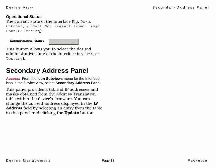
Operational StatusThe current state of the interface (Up, Down, Unknown, Dormant, Not Present, Lower Layer Down, or Testing).
This button allows you to select the desired administrative state of the interface (On, Off, or Testing).
Secondary Address PanelAccess: From the Icon Subviews menu for the Interface icon in the Device view, select Secondary Address Panel.
This panel provides a table of IP addresses and masks obtained from the Address Translation table within the device’s firmware. You can change the current address displayed in the IP Address field by selecting an entry from the table in this panel and clicking the Update button.
Administrative Status
D e v i c e M a n a g e m e n t Page 14 P a c k e t e e r
Device Topology View
This section describes the Device Topology view available for models of Packeteer devices in SPECTRUM.
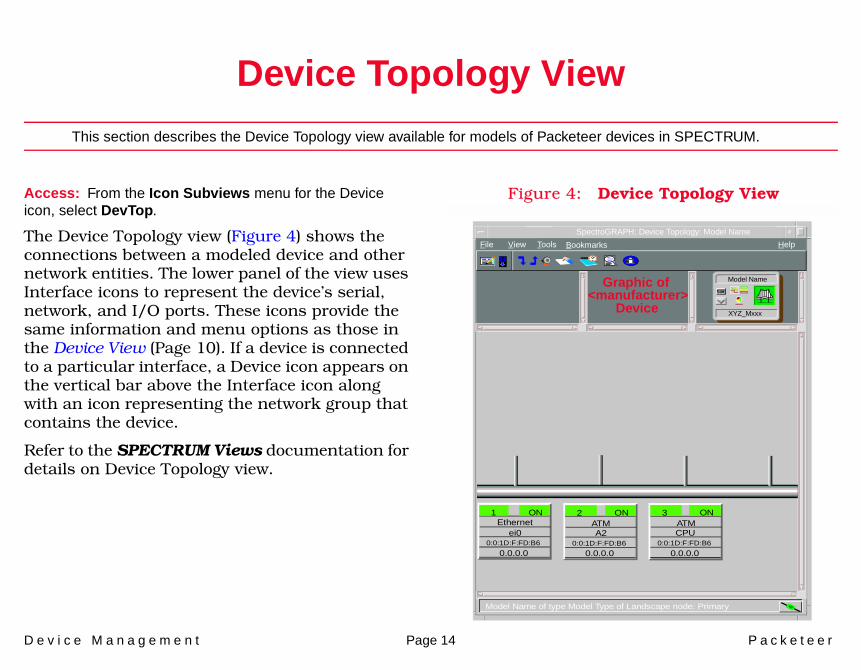
Access: From the Icon Subviews menu for the Device icon, select DevTop.
The Device Topology view (Figure 4) shows the connections between a modeled device and other network entities. The lower panel of the view uses Interface icons to represent the device’s serial, network, and I/O ports. These icons provide the same information and menu options as those in the Device View (Page 10). If a device is connected to a particular interface, a Device icon appears on the vertical bar above the Interface icon along with an icon representing the network group that contains the device.
Refer to the SPECTRUM Views documentation for details on Device Topology view.
Figure 4: Device Topology View
File View HelpTools
1Ethernet
0:0:1D:F:FD:B6ei0
0.0.0.0
ON 2ATM
0:0:1D:F:FD:B6A2
0.0.0.0
ON 3ATM
0:0:1D:F:FD:B6CPU
0.0.0.0
ON
XYZ_Mxxx
Model Name
Bookmarks
SpectroGRAPH: Device Topology: Model Name
Graphic of<manufacturer>
Device
Model Name of type Model Type of Landscape node: Primary
D e v i c e M a n a g e m e n t Page 15 P a c k e t e e r
Application Views
This section describes the main Application view and the associated application-specific subviews available for models of Packeteer devices in SPECTRUM.
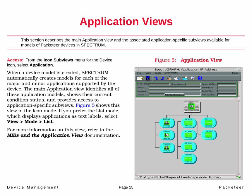
Access: From the Icon Subviews menu for the Device icon, select Application.
When a device model is created, SPECTRUM automatically creates models for each of the major and minor applications supported by the device. The main Application view identifies all of these application models, shows their current condition status, and provides access to application-specific subviews. Figure 5 shows this view in the Icon mode. If you prefer the List mode, which displays applications as text labels, select View > Mode > List.
For more information on this view, refer to the MIBs and the Application View documentation.
Figure 5: Application View
JK2 of type PacketShaper of Landscape node: Primary
Model Name
Contact
Description
Location Primary Application
System Up Time
Manufacturer
Device Type
Serial Number
Network Address
File View HelpTools
JK2
APVntg ASM50
JK2_MIB-II
MP2-Agent
JK2_ICMP
ICMP_App
Bridge App SCommonA
PSCommonA
PSCommonApp
_PSRTMApp
PSRTMApp
PSRTMApp
JK2 Static
Transparen
GenRtrApp
Static_App
arent_App
SNMP2_Agent
ICMPApp
System2_App
UDP2_App
JK2_System
JK2_UDP2
System2_App
UDP2_App
Bookmarks
i
SpectroGRAPH: Application: IP Address
A p p l i c a t i o n V i e w s S u p p o r t e d A p p l i c a t i o n s
D e v i c e M a n a g e m e n t Page 16 P a c k e t e e r
Supported ApplicationsSPECTRUM’s applications can be grouped within two general categories as follows:
• Applications associated with non proprietary MIBs. See Common Applications below.
• Applications associated with device-specific MIBs. See Device-Specific MIBs (Page 17).
Common ApplicationsFor the most part, these applications represent the non proprietary MIBs supported by devices. Listed below (beneath the title of the SPECTRUM document that describes them) are some of the common applications currently supported by SPECTRUM. Refer to these documents when your devices support these applications.
• Routing Applications- Generic Routing- Repeater- AppleTalk- DECnet
- OSPF- OSPF2- BGP4- VRRP
• Bridging Applications- Ethernet Special Database- Spanning Tree- Static- Transparent- PPP Bridging- Source Routing- Translation- QBridge
• MIB II Applications- SNMP- IP- ICMP- TCP- System2- UDP
• Transmission Applications- FDDI- Point to Point- DS1- DS3- RS-232
Note:Note:
The documents listed below (in bold font) are available for viewing at:
www.aprisma.com/manuals/
A p p l i c a t i o n V i e w s S u p p o r t e d A p p l i c a t i o n s
D e v i c e M a n a g e m e n t Page 17 P a c k e t e e r
- WAN- Frame Relay- Token Ring- Ethernet- Fast Ethernet- rfc1317App- rfc1285App- rfc1315App- 802.11App- SONET
• Technology Applications- APPN- ATM Client- DHCP- PNNI- rfc1316App- DLSw
• DOCSIS Applications- DOCSISCblDvApp - DOCSISQOSApp- DOCSISBPI2App - DOCSISBPIApp - DOCSISIFApp
• Digital Subscriber Line (DSL) Applications- ADSL
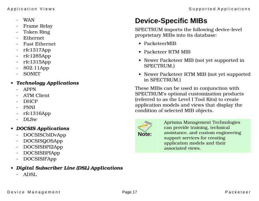
Device-Specific MIBsSPECTRUM imports the following device-level proprietary MIBs into its database:
• PacketeerMIB
• Packeteer RTM MIB
• Newer Packeteer MIB (not yet supported in SPECTRUM.)
• Newer Packeteer RTM MIB (not yet supported in SPECTRUM.)
These MIBs can be used in conjunction with SPECTRUM’s optional customization products (referred to as the Level I Tool Kits) to create application models and views that display the condition of selected MIB objects.
Note:Note:
Aprisma Management Technologies can provide training, technical assistance, and custom engineering support services for creating application models and their associated views.
A p p l i c a t i o n V i e w s P a c k e t e e r P a c k e t S h a p e r C o m m o n A p p l i c a t i o n
D e v i c e M a n a g e m e n t Page 18 P a c k e t e e r
The following device-specific applications are described in the remainder of this section:
• Packeteer Packet Shaper Common Application (Page 18)
• Response Time Management Configuration View (Page 20)
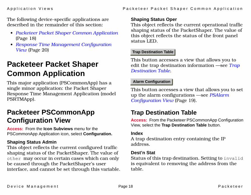
Packeteer Packet Shaper Common ApplicationThis major application (PSCommonApp) has a single minor application: the Packet Shaper Response Time Management Application (model PSRTMApp).
Packeteer PSCommonApp Configuration ViewAccess: From the Icon Subviews menu for the PSCommonApp Application icon, select Configuration.
Shaping Status AdminThis object reflects the current configured traffic shaping status of the PacketShaper. The value of other may occur in certain cases which can only be caused through the PacketShaper’s user interface, and cannot be set through this variable.
Shaping Status OperThis object reflects the current operational traffic shaping status of the PacketShaper. The value of this object reflects the status of the front panel status LED.
This button accesses a view that allows you to edit the trap destination information —see Trap Destination Table.
This button accesses a view that allows you to set up the alarm configurations —see PSAlarm Configuration View (Page 19).
Trap Destination TableAccess: From the Packeteer PSCommonApp Configuration View, select the Trap Destination Table button.
IndexA trap destination entry containing the IP address.
Dest’n StatStatus of this trap destination. Setting to invalid is equivalent to removing the address from the table.
Trap Destination Table
Alarm Configuration
A p p l i c a t i o n V i e w s P a c k e t e e r P a c k e t S h a p e r C o m m o n A p p l i c a t i o n
D e v i c e M a n a g e m e n t Page 19 P a c k e t e e r
Dest’n Add (write only)A shortcut for adding a host to trapDestTable. If the name is not in n.n.n.n IP address form, then the agent attempts to look it up via DNS.
Dest’n Remove (write only)A shortcut for removing an IP address from trapDestTable. If the name is not in n.n.n.n IP address form, then the agent attempts to look it up via DNS.
PSAlarm Configuration ViewAccess: From the Packeteer PSCommonApp Configuration View, select the Alarm Configuration button.
Inside Link CountThe number of MIB-II LinkDown traps sent by the agent since the last reset, where ifIndex was for the Inside Link.
Site Router countThe number of AlarmSiteRouter traps sent by the agent since the last reset.
Power System One countThe number of AlarmPowerSystemOne traps sent by the agent since the last reset.
Power System Two CountThe number of AlarmPowerSystemTwo traps sent by the agent since the last reset.
Fan One countThe number of AlarmFanOne traps sent by the agent since the last reset.
Fan Two CountThe number of AlarmFanTwo traps sent by the agent since the last reset.
Config File CountThe number of AlarmCfgFile traps sent by the agent since the last reset.
Measurement Engine CountThe number of psAlarmMeasurementEngine traps sent by the agent since the last reset.
Outside Link CountThe number of MIB-II LinkDown traps sent by the agent since the last reset, where ifIndex was for the Outside link.
Site Router StatusStatus of the site router. A status of gone means that PacketShaper has stopped getting ARP replies from the router. Error-inside means that it most recently got a reply, but from the inside. None means that no site router was configured.
Power System One StatusThe operational status of the first power system of the device.
A p p l i c a t i o n V i e w s P a c k e t e e r P a c k e t S h a p e r C o m m o n A p p l i c a t i o n
D e v i c e M a n a g e m e n t Page 20 P a c k e t e e r
Power System Two StatusThe operational status of the second power supply of the device.
Fan One StatusThe operational status of the first fan of the device.
Fan Two StatusThe operational status of the second fan of the device.
Config File StatusDisplays whether the configuration file has been corrupted. valid signifies no problems. corrupted signifies that the configuration file has been corrupted.
Measurement Engine StatThe current status of the Measurement engine.
Response Time Management Configuration ViewAccess: From the Icon Subviews menu for the PSRTMApp Application icon, select Configuration.
A table of parameters configuring the Response Time Management feature for each class.
Threshold ConfigThis section allows you to view the configuration thresholds. Column headings are as follows:
IndexAn entry containing the configurable Response Time Management parameters for a given class.
TotDelThrshldThe time, in milliseconds, that constitutes the acceptable limit of aggregate delay for this class.
SvrLevThrshldThe percentage of transactions required NOT to be over threshold. If more than this percentage of transactions in an interval are over threshold, then this interval is counted in the TotDelThrshld variable. The default is 100.
Total Delay Bucket ConfThis section allows you to configure the total delay buckets. Column headings are as follows:
Index.DelayBucketLimitThe lower limit of this bucket, in milliseconds.
A p p l i c a t i o n V i e w s P a c k e t e e r P a c k e t S h a p e r C o m m o n A p p l i c a t i o n
D e v i c e M a n a g e m e n t Page 21 P a c k e t e e r
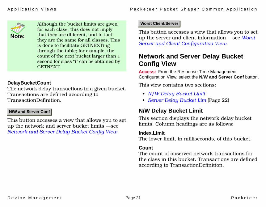
DelayBucketCountThe network delay transactions in a given bucket. Transactions are defined according to TransactionDefinition.
This button accesses a view that allows you to set up the network and server bucket limits —see Network and Server Delay Bucket Config View.
This button accesses a view that allows you to set up the server and client information —see Worst Server and Client Configuration View.
Network and Server Delay Bucket Config ViewAccess: From the Response Time Management Configuration View, select the N/W and Server Conf button.
This view contains two sections:
• N/W Delay Bucket Limit• Server Delay Bucket Lim (Page 22)
N/W Delay Bucket LimitThis section displays the network delay bucket limits. Column headings are as follows:
Index.LimitThe lower limit, in milliseconds, of this bucket.
CountThe count of observed network transactions for the class in this bucket. Transactions are defined according to TransactionDefinition.
Note:Note:
Although the bucket limits are given for each class, this does not imply that they are different, and in fact they are the same for all classes. This is done to facilitate GETNEXTing through the table; for example, the count of the next bucket larger than 1 second for class “i” can be obtained by GETNEXT.
N/W and Server Conf
Worst Client/Server
A p p l i c a t i o n V i e w s P a c k e t e e r P a c k e t S h a p e r C o m m o n A p p l i c a t i o n
D e v i c e M a n a g e m e n t Page 22 P a c k e t e e r
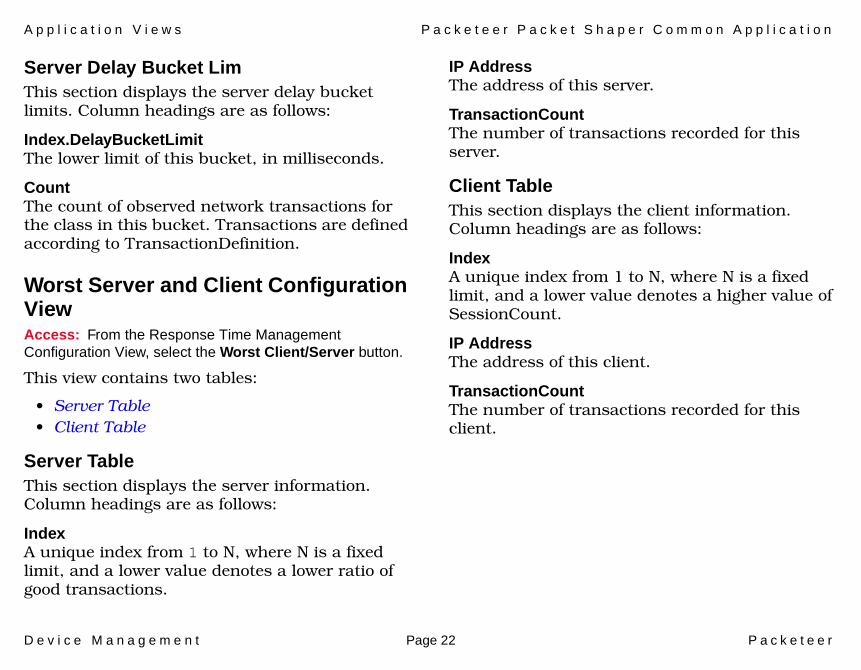
Server Delay Bucket LimThis section displays the server delay bucket limits. Column headings are as follows:
Index.DelayBucketLimitThe lower limit of this bucket, in milliseconds.
CountThe count of observed network transactions for the class in this bucket. Transactions are defined according to TransactionDefinition.
Worst Server and Client Configuration ViewAccess: From the Response Time Management Configuration View, select the Worst Client/Server button.
This view contains two tables:
• Server Table• Client Table
Server TableThis section displays the server information. Column headings are as follows:
IndexA unique index from 1 to N, where N is a fixed limit, and a lower value denotes a lower ratio of good transactions.
IP AddressThe address of this server.
TransactionCountThe number of transactions recorded for this server.
Client TableThis section displays the client information. Column headings are as follows:
IndexA unique index from 1 to N, where N is a fixed limit, and a lower value denotes a higher value of SessionCount.
IP AddressThe address of this client.
TransactionCountThe number of transactions recorded for this client.
D e v i c e M a n a g e m e n t Page 23 P a c k e t e e r
Performance Views
This section introduces the Performance views.
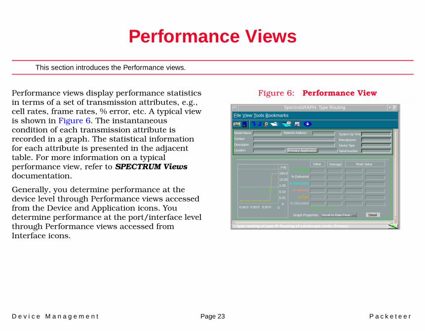
Performance views display performance statistics in terms of a set of transmission attributes, e.g., cell rates, frame rates, % error, etc. A typical view is shown in Figure 6. The instantaneous condition of each transmission attribute is recorded in a graph. The statistical information for each attribute is presented in the adjacent table. For more information on a typical performance view, refer to SPECTRUM Views documentation.
Generally, you determine performance at the device level through Performance views accessed from the Device and Application icons. You determine performance at the port/interface level through Performance views accessed from Interface icons.
Figure 6: Performance View
SpectroGRAPH: Type Routing
Model Name
Contact
Description
Location
Network Address System Up Time
Manufacturer
Device Type
Serial Number
Log
100.0
10.00
1.00
0.10
0.01
000:40:0 0:30:0 0:20:0
Value Average Peak Value
* Frame Rate
% Delivered
% Forwarded
% Transmit
% Error
DetailGraph Properties Scroll to Date-Time
File View Tools Bookmarks
% Discarded*Frames per second
type routing of type IP Routing of Landscape node: Primary
Primary Application
P e r f o r m a n c e V i e w s P a c k e t e e r P S C o m m o n A p p P e r f o r m a n c e V i e w
D e v i c e M a n a g e m e n t Page 24 P a c k e t e e r
The following performance views are described in this section:
• Packeteer PSCommonApp Performance View (Page 24)
• Packeteer PSRTMApp Performance View (Page 30)
Packeteer PSCommonApp Performance ViewAccess: From the Icon Subviews menu for the PSCommonoApp icon, select Performance.
The performance information is based on the PSCommonApp (the primary application for this device). This view includes three tables that contain statistical objects for a link.
• Link Table 1• Link Table 2 (Page 25)• Link Table 3 (Page 25)
The view also provides button access to a Partition Table (Page 26) and a Class Table (Page 28).
Link Table 1Link IndexA unique ID for a link.
Link NameA unique name for a link.
BytecountThe byte count in the link.
BytecountHiThe High 32 bits of byte count in the link.
PktsThe packet count in the link.
DataPktsThe TCP data packet count in the link.
ReTxsThe TCP retransmit packet count in the link.
ReTxTossesThe TCP tossed retransmit packet count in the link.
CirFailsThe count of CIR fails events in the link.
CirAllocsThe count of CIR alloc events in the link.
EirAllocsThe count of EIR alloc events in the link.
P e r f o r m a n c e V i e w s P a c k e t e e r P S C o m m o n A p p P e r f o r m a n c e V i e w
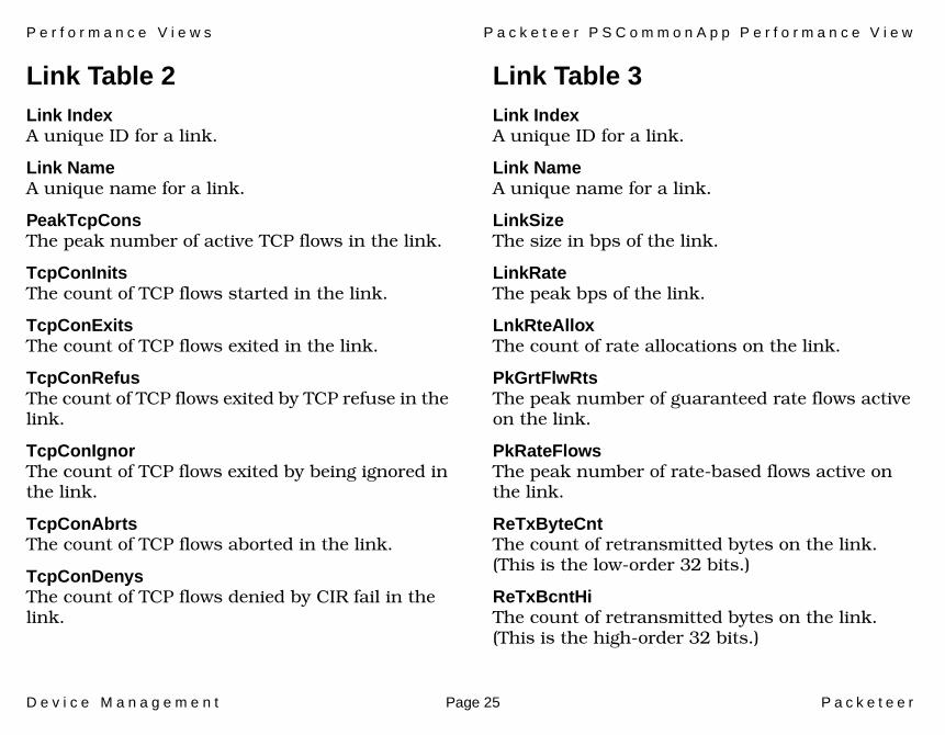
D e v i c e M a n a g e m e n t Page 25 P a c k e t e e r
Link Table 2Link IndexA unique ID for a link.
Link NameA unique name for a link.
PeakTcpConsThe peak number of active TCP flows in the link.
TcpConInitsThe count of TCP flows started in the link.
TcpConExitsThe count of TCP flows exited in the link.
TcpConRefusThe count of TCP flows exited by TCP refuse in the link.
TcpConIgnorThe count of TCP flows exited by being ignored in the link.
TcpConAbrtsThe count of TCP flows aborted in the link.
TcpConDenysThe count of TCP flows denied by CIR fail in the link.
Link Table 3Link IndexA unique ID for a link.
Link NameA unique name for a link.
LinkSizeThe size in bps of the link.
LinkRateThe peak bps of the link.
LnkRteAlloxThe count of rate allocations on the link.
PkGrtFlwRtsThe peak number of guaranteed rate flows active on the link.
PkRateFlowsThe peak number of rate-based flows active on the link.
ReTxByteCntThe count of retransmitted bytes on the link. (This is the low-order 32 bits.)
ReTxBcntHiThe count of retransmitted bytes on the link. (This is the high-order 32 bits.)
P e r f o r m a n c e V i e w s P a c k e t e e r P S C o m m o n A p p P e r f o r m a n c e V i e w
D e v i c e M a n a g e m e n t Page 26 P a c k e t e e r
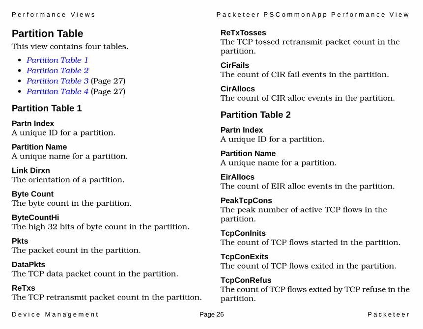
Partition Table This view contains four tables.
• Partition Table 1• Partition Table 2• Partition Table 3 (Page 27)• Partition Table 4 (Page 27)
Partition Table 1
Partn IndexA unique ID for a partition.
Partition NameA unique name for a partition.
Link DirxnThe orientation of a partition.
Byte CountThe byte count in the partition.
ByteCountHiThe high 32 bits of byte count in the partition.
PktsThe packet count in the partition.
DataPktsThe TCP data packet count in the partition.
ReTxsThe TCP retransmit packet count in the partition.
ReTxTossesThe TCP tossed retransmit packet count in the partition.
CirFailsThe count of CIR fail events in the partition.
CirAllocsThe count of CIR alloc events in the partition.
Partition Table 2
Partn IndexA unique ID for a partition.
Partition NameA unique name for a partition.
EirAllocsThe count of EIR alloc events in the partition.
PeakTcpConsThe peak number of active TCP flows in the partition.
TcpConInitsThe count of TCP flows started in the partition.
TcpConExitsThe count of TCP flows exited in the partition.
TcpConRefusThe count of TCP flows exited by TCP refuse in the partition.
P e r f o r m a n c e V i e w s P a c k e t e e r P S C o m m o n A p p P e r f o r m a n c e V i e w
D e v i c e M a n a g e m e n t Page 27 P a c k e t e e r
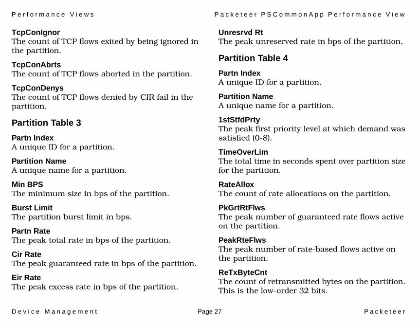
TcpConIgnorThe count of TCP flows exited by being ignored in the partition.
TcpConAbrtsThe count of TCP flows aborted in the partition.
TcpConDenysThe count of TCP flows denied by CIR fail in the partition.
Partition Table 3
Partn IndexA unique ID for a partition.
Partition NameA unique name for a partition.
Min BPSThe minimum size in bps of the partition.
Burst LimitThe partition burst limit in bps.
Partn RateThe peak total rate in bps of the partition.
Cir RateThe peak guaranteed rate in bps of the partition.
Eir RateThe peak excess rate in bps of the partition.
Unresrvd RtThe peak unreserved rate in bps of the partition.
Partition Table 4
Partn IndexA unique ID for a partition.
Partition NameA unique name for a partition.
1stStfdPrtyThe peak first priority level at which demand was satisfied (0-8).
TimeOverLimThe total time in seconds spent over partition size for the partition.
RateAlloxThe count of rate allocations on the partition.
PkGrtRtFlwsThe peak number of guaranteed rate flows active on the partition.
PeakRteFlwsThe peak number of rate-based flows active on the partition.
ReTxByteCntThe count of retransmitted bytes on the partition. This is the low-order 32 bits.
P e r f o r m a n c e V i e w s P a c k e t e e r P S C o m m o n A p p P e r f o r m a n c e V i e w
D e v i c e M a n a g e m e n t Page 28 P a c k e t e e r
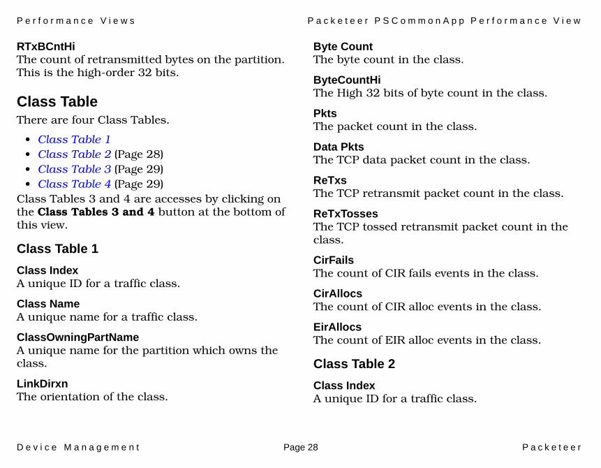
RTxBCntHiThe count of retransmitted bytes on the partition. This is the high-order 32 bits.
Class TableThere are four Class Tables.
• Class Table 1• Class Table 2 (Page 28)• Class Table 3 (Page 29)• Class Table 4 (Page 29)
Class Tables 3 and 4 are accesses by clicking on the Class Tables 3 and 4 button at the bottom of this view.
Class Table 1
Class IndexA unique ID for a traffic class.
Class NameA unique name for a traffic class.
ClassOwningPartNameA unique name for the partition which owns the class.
LinkDirxnThe orientation of the class.
Byte CountThe byte count in the class.
ByteCountHiThe High 32 bits of byte count in the class.
PktsThe packet count in the class.
Data PktsThe TCP data packet count in the class.
ReTxsThe TCP retransmit packet count in the class.
ReTxTossesThe TCP tossed retransmit packet count in the class.
CirFailsThe count of CIR fails events in the class.
CirAllocsThe count of CIR alloc events in the class.
EirAllocsThe count of EIR alloc events in the class.
Class Table 2
Class IndexA unique ID for a traffic class.
P e r f o r m a n c e V i e w s P a c k e t e e r P S C o m m o n A p p P e r f o r m a n c e V i e w
D e v i c e M a n a g e m e n t Page 29 P a c k e t e e r
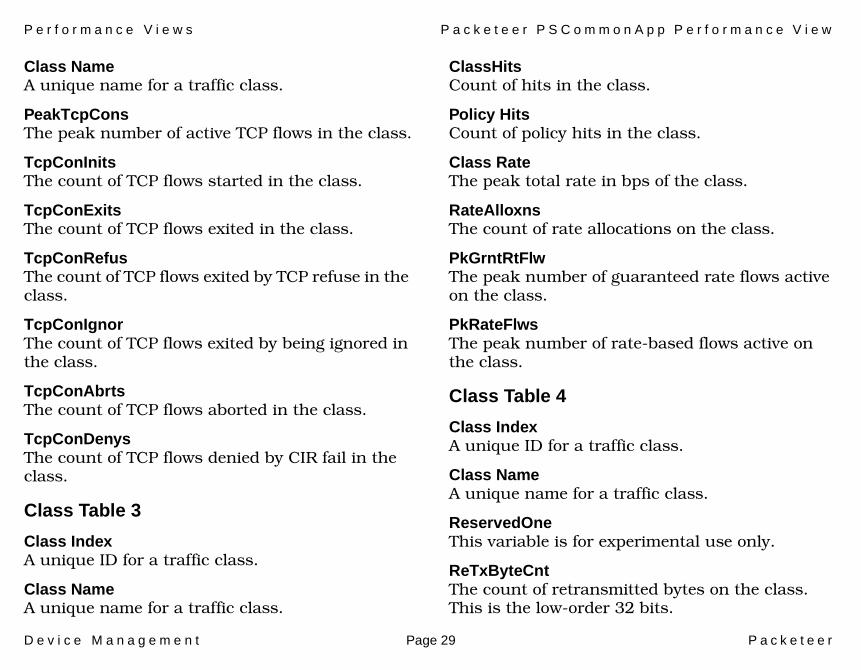
Class NameA unique name for a traffic class.
PeakTcpConsThe peak number of active TCP flows in the class.
TcpConInitsThe count of TCP flows started in the class.
TcpConExitsThe count of TCP flows exited in the class.
TcpConRefusThe count of TCP flows exited by TCP refuse in the class.
TcpConIgnorThe count of TCP flows exited by being ignored in the class.
TcpConAbrtsThe count of TCP flows aborted in the class.
TcpConDenysThe count of TCP flows denied by CIR fail in the class.
Class Table 3
Class IndexA unique ID for a traffic class.
Class NameA unique name for a traffic class.
ClassHitsCount of hits in the class.
Policy HitsCount of policy hits in the class.
Class RateThe peak total rate in bps of the class.
RateAlloxnsThe count of rate allocations on the class.
PkGrntRtFlwThe peak number of guaranteed rate flows active on the class.
PkRateFlwsThe peak number of rate-based flows active on the class.
Class Table 4
Class IndexA unique ID for a traffic class.
Class NameA unique name for a traffic class.
ReservedOneThis variable is for experimental use only.
ReTxByteCntThe count of retransmitted bytes on the class. This is the low-order 32 bits.
P e r f o r m a n c e V i e w s P a c k e t e e r P S R T M A p p P e r f o r m a n c e V i e w
D e v i c e M a n a g e m e n t Page 30 P a c k e t e e r
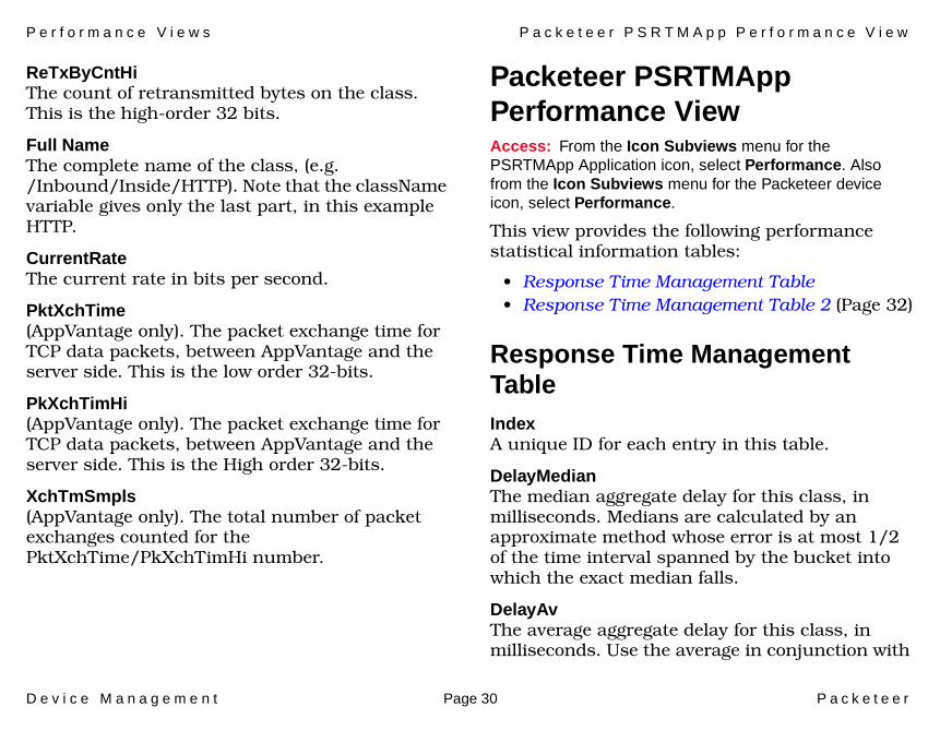
ReTxByCntHiThe count of retransmitted bytes on the class. This is the high-order 32 bits.
Full NameThe complete name of the class, (e.g. /Inbound/Inside/HTTP). Note that the className variable gives only the last part, in this example HTTP.
CurrentRateThe current rate in bits per second.
PktXchTime(AppVantage only). The packet exchange time for TCP data packets, between AppVantage and the server side. This is the low order 32-bits.
PkXchTimHi(AppVantage only). The packet exchange time for TCP data packets, between AppVantage and the server side. This is the High order 32-bits.
XchTmSmpls(AppVantage only). The total number of packet exchanges counted for the PktXchTime/PkXchTimHi number.
Packeteer PSRTMApp Performance ViewAccess: From the Icon Subviews menu for the PSRTMApp Application icon, select Performance. Also from the Icon Subviews menu for the Packeteer device icon, select Performance.
This view provides the following performance statistical information tables:
• Response Time Management Table• Response Time Management Table 2 (Page 32)
Response Time Management TableIndexA unique ID for each entry in this table.
DelayMedianThe median aggregate delay for this class, in milliseconds. Medians are calculated by an approximate method whose error is at most 1/2 of the time interval spanned by the bucket into which the exact median falls.
DelayAvThe average aggregate delay for this class, in milliseconds. Use the average in conjunction with
P e r f o r m a n c e V i e w s P a c k e t e e r P S R T M A p p P e r f o r m a n c e V i e w
D e v i c e M a n a g e m e n t Page 31 P a c k e t e e r
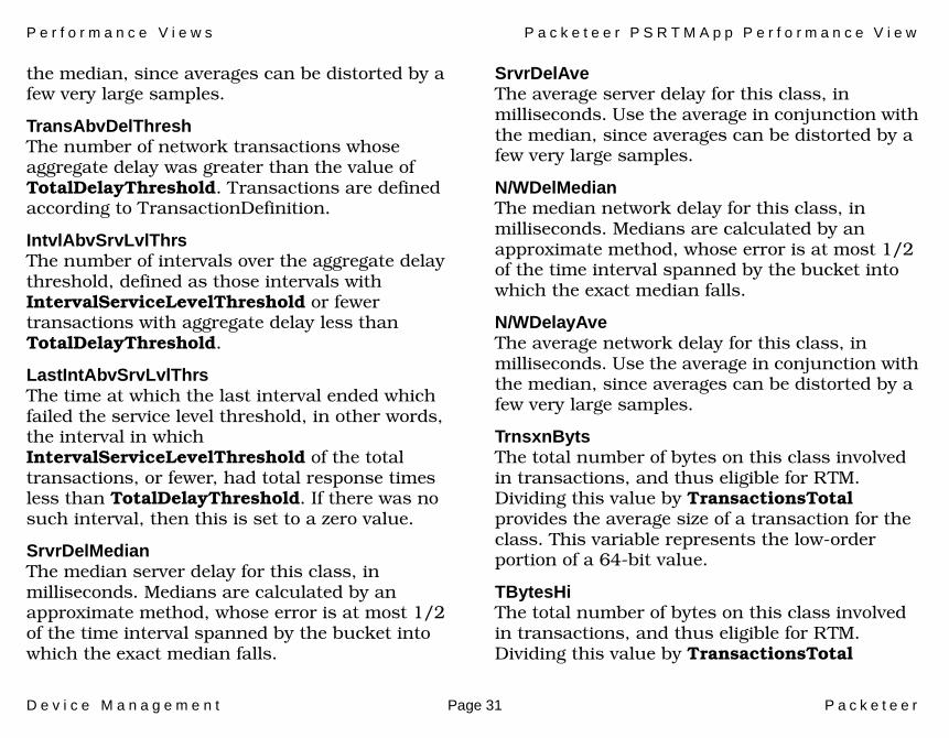
the median, since averages can be distorted by a few very large samples.
TransAbvDelThreshThe number of network transactions whose aggregate delay was greater than the value of TotalDelayThreshold. Transactions are defined according to TransactionDefinition.
IntvlAbvSrvLvlThrsThe number of intervals over the aggregate delay threshold, defined as those intervals with IntervalServiceLevelThreshold or fewer transactions with aggregate delay less than TotalDelayThreshold.
LastIntAbvSrvLvlThrsThe time at which the last interval ended which failed the service level threshold, in other words, the interval in which IntervalServiceLevelThreshold of the total transactions, or fewer, had total response times less than TotalDelayThreshold. If there was no such interval, then this is set to a zero value.
SrvrDelMedianThe median server delay for this class, in milliseconds. Medians are calculated by an approximate method, whose error is at most 1/2 of the time interval spanned by the bucket into which the exact median falls.
SrvrDelAveThe average server delay for this class, in milliseconds. Use the average in conjunction with the median, since averages can be distorted by a few very large samples.
N/WDelMedianThe median network delay for this class, in milliseconds. Medians are calculated by an approximate method, whose error is at most 1/2 of the time interval spanned by the bucket into which the exact median falls.
N/WDelayAveThe average network delay for this class, in milliseconds. Use the average in conjunction with the median, since averages can be distorted by a few very large samples.
TrnsxnBytsThe total number of bytes on this class involved in transactions, and thus eligible for RTM. Dividing this value by TransactionsTotal provides the average size of a transaction for the class. This variable represents the low-order portion of a 64-bit value.
TBytesHiThe total number of bytes on this class involved in transactions, and thus eligible for RTM. Dividing this value by TransactionsTotal
P e r f o r m a n c e V i e w s P a c k e t e e r P S R T M A p p P e r f o r m a n c e V i e w
D e v i c e M a n a g e m e n t Page 32 P a c k e t e e r
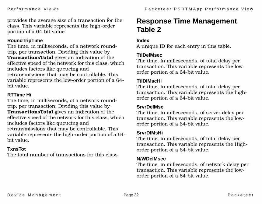
provides the average size of a transaction for the class. This variable represents the high-order portion of a 64-bit value
RoundTripTimeThe time, in milliseconds, of a network round-trip, per transaction. Dividing this value by TransactionsTotal gives an indication of the effective speed of the network for this class, which includes factors like queueing and retransmissions that may be controllable. This variable represents the low-order portion of a 64-bit value.
RTTime HiThe time, in milliseconds, of a network round-trip, per transaction. Dividing this value by TransactionsTotal gives an indication of the effective speed of the network for this class, which includes factors like queueing and retransmissions that may be controllable. This variable represents the high-order portion of a 64-bit value.
TxnsTotThe total number of transactions for this class.
Response Time Management Table 2IndexA unique ID for each entry in this table.
TtlDelMsecThe time, in milleseconds, of total delay per transaction. This variable represents the low-order portion of a 64-bit value.
TtlDlMscHiThe time, in milleseconds, of total delay per transaction. This variable represents the high-order portion of a 64-bit value.
SrvrDelMscThe time, in milleseconds, of server delay per transaction. This variable represents the low-order portion of a 64-bit value.
SrvrDlMsHiThe time, in milleseconds, of total delay per transaction. This variable represents the High-order portion of a 64-bit value.
N/WDelMsecThe time, in milleseconds, of network delay per transaction. This variable represents the low-order portion of a 64-bit value.
P e r f o r m a n c e V i e w s P a c k e t e e r P S R T M A p p P e r f o r m a n c e V i e w
D e v i c e M a n a g e m e n t Page 33 P a c k e t e e r
N/WDelMsHiThe time, in milleseconds, of network delay per transaction. This variable represents the high-order portion of a 64-bit value.
D e v i c e M a n a g e m e n t Page 34 P a c k e t e e r
Configuration Views
This section describes the Configuration views available for models of the Packeteer devices in SPECTRUM.
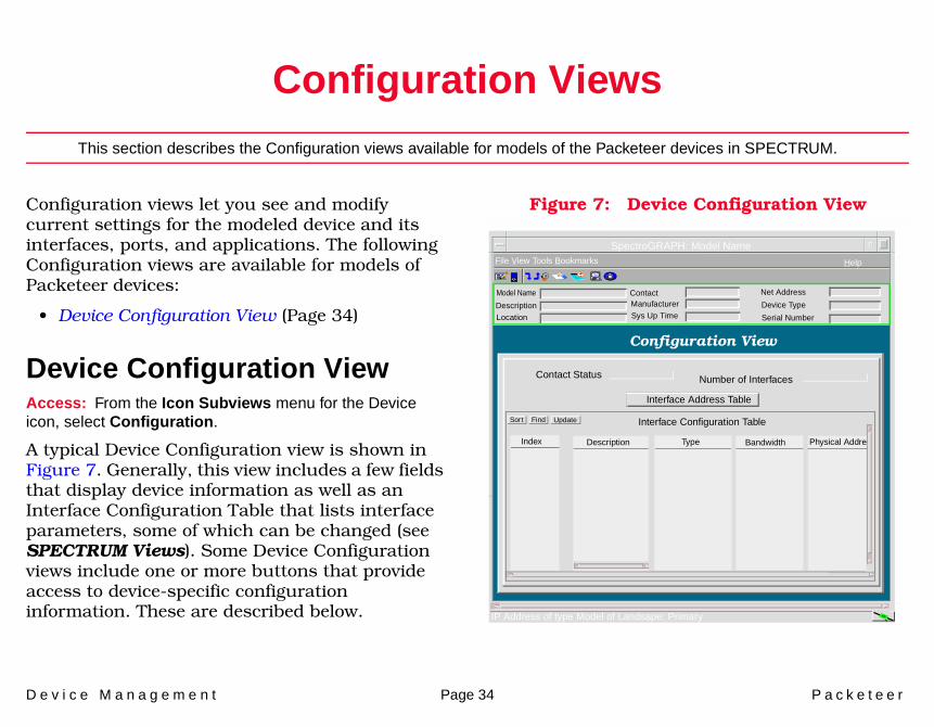
Configuration views let you see and modify current settings for the modeled device and its interfaces, ports, and applications. The following Configuration views are available for models of Packeteer devices:
• Device Configuration View (Page 34)
Device Configuration ViewAccess: From the Icon Subviews menu for the Device icon, select Configuration.
A typical Device Configuration view is shown in Figure 7. Generally, this view includes a few fields that display device information as well as an Interface Configuration Table that lists interface parameters, some of which can be changed (see SPECTRUM Views). Some Device Configuration views include one or more buttons that provide access to device-specific configuration information. These are described below.
Figure 7: Device Configuration View
SpectroGRAPH: Model Name
Model Name
File View Tools Bookmarks Help
Description
Location
ContactManufacturer
Sys Up Time
Net Address
Device Type
Serial Number
Configuration View
Contact Status Number of Interfaces
Interface Address Table
Sort Interface Configuration Table
Index Description Type Bandwidth Physical Addre
IP Address of type Model of Landsape: Primary
Find Update
C o n f i g u r a t i o n V i e w s D e v i c e C o n f i g u r a t i o n V i e w
D e v i c e M a n a g e m e n t Page 35 P a c k e t e e r
Refer to the SPECTRUM Views documentation.
Refer to the SPECTRUM Views documentation.
Redundancy and Model Reconfiguration Options
IP IF Address Translation
D e v i c e M a n a g e m e n t Page 36 P a c k e t e e r
Model Information View
This section provides a brief description of the Model Information views available for models of Packeteer devices in SPECTRUM.
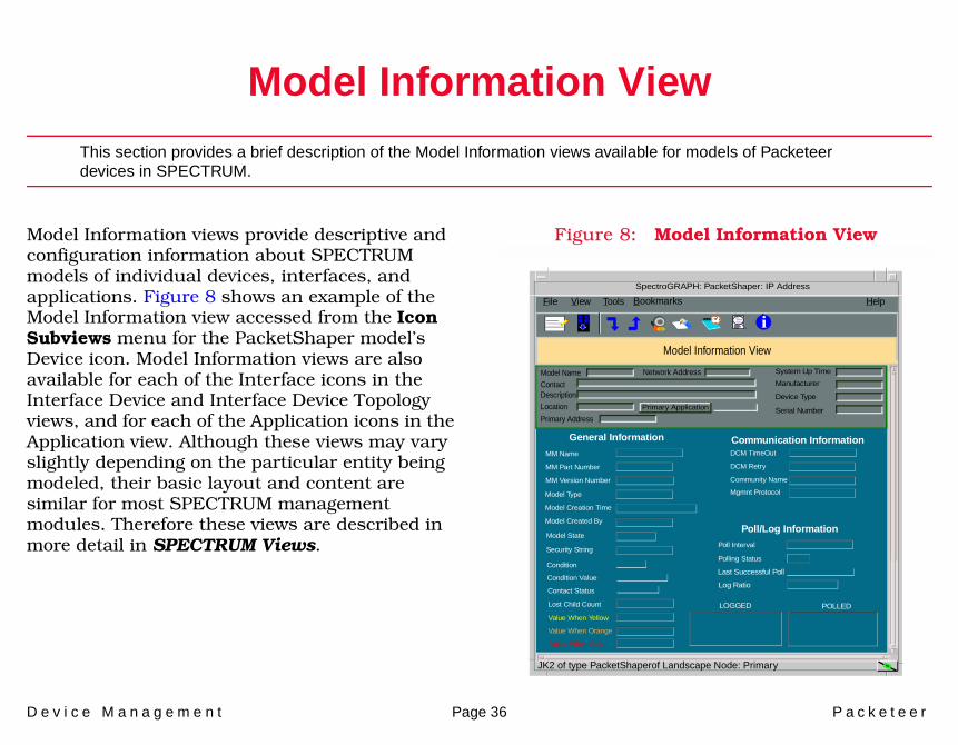
Model Information views provide descriptive and configuration information about SPECTRUM models of individual devices, interfaces, and applications. Figure 8 shows an example of the Model Information view accessed from the Icon Subviews menu for the PacketShaper model’s Device icon. Model Information views are also available for each of the Interface icons in the Interface Device and Interface Device Topology views, and for each of the Application icons in the Application view. Although these views may vary slightly depending on the particular entity being modeled, their basic layout and content are similar for most SPECTRUM management modules. Therefore these views are described in more detail in SPECTRUM Views.
Figure 8: Model Information View
JK2 of type PacketShaperof Landscape Node: Primary
Primary Application
System Up Time
Manufacturer
Device Type
Serial Number
Network AddressModel NameContactDescriptionLocation
File View HelpTools
MM Version Number
MM Name
MM Part Number
General Information
Model Created By
Model Type
Model Creation Time
Model State
Security String
Communication Information
Community Name
DCM TimeOut
DCM Retry
Poll/Log Information
Poll Interval
Polling StatusCondition
Condition Value
Contact Status
Lost Child Count
Value When Yellow
Value When Orange
Value When Red
Last Successful Poll
Log Ratio
LOGGED POLLED
Model Information View
Bookmarks
i
SpectroGRAPH: PacketShaper: IP Address
Primary Address
Mgmnt Protocol
D e v i c e M a n a g e m e n t Page 37 P a c k e t e e r
Index
AAddress
Interface IP 12Physical (MAC) 12Translation 13
Admin Status 11Application
Device-specificMotorola Data Compression
Application (MotDCApp) 18
CConfiguration
Device 34
DDevice icon 7Devices supported by this module 6Device-Specific applications 18
IIcons
Device 7Interface 11
InterfaceStatus 12Type, Device 11
MMask 13MIB Information 17Model Information views 36Model type 7MotMPRouter 7
NNetwork I/O ports 14Network Type 12
PPerformance Statistics 23
Port Number, Device 11
RRequired Reading 5
SSerial ports 14Statistics
Routing Frame Transmission 24Supported devices 6
AppVantage ASM-30 6AppVantage ASM-50 6AppVantage ASM-70 6AppVantage ASM-90 6Packeteer PacketShaper 1500 6Packeteer PacketShaper 2500 6Packeteer PacketShaper 4500 6PacketShaper-6500 6
TThreshold Information 12

I n d e x I n d e x
D e v i c e M a n a g e m e n t Page 38 P a c k e t e e r
VViews
Application 15Model Information 36