Packet Switching - Colorado State Universitygersch/cs457/03PacketSwitching.pdf · Packet Switching...
47
Packet Switching CS457 Fall 2014
Transcript of Packet Switching - Colorado State Universitygersch/cs457/03PacketSwitching.pdf · Packet Switching...
Packet Switching
CS457 Fall 2014

Topics
• Learning bridges/switches • Spanning tree algorithm • Virtual LANs

Switches: Traffic Isolation • Switch breaks subnet into LAN segments • Switch filters packets
– Frame only forwarded to the necessary segments – Segments become separate collision domains – Bridge: a switch that connects two LAN segments
hub hub hub
switch/bridge
collision domain collision domain
collision domain

Motivation For Self Learning � Switches forward frames selectively
� Forward frames only on segments that need them
� Switch table � Maps destination MAC address to outgoing interface � Goal: construct the switch table automatically
switch
A!
B!
C!
D!

Self Learning: Building the Table • When a frame arrives
– Inspect the source MAC address – Associate the address with the incoming interface – Store the mapping in the switch table – Use a time-to-live field to eventually forget the mapping
A!
B!
C!
D!
Switch learns how to reach A.!

Self Learning: Handling Misses � When frame arrives with unfamiliar destination
� Forward the frame out all of the interfaces � … except for the one where the frame arrived � Hopefully, this case won’t happen very often
A!
B!
C!
D!
When in doubt, shout!!

Switch Filtering/Forwarding When switch receives a frame:
index switch table using MAC dest address if entry found for destination
then{ if dest on segment from which frame arrived
then drop the frame else forward the frame on interface indicated } else flood
forward on all but the interface on which the frame arrived

Flooding Can Lead to Loops � Switches sometimes need to broadcast frames
� Upon receiving a frame with an unfamiliar destination � Upon receiving a frame sent to the broadcast address
� Broadcasting is implemented by flooding � Transmitting frame out every interface � … except the one where the frame arrived
� Flooding can lead to forwarding loops � E.g., if the network contains a cycle of switches � Either accidentally, or by design for higher reliability
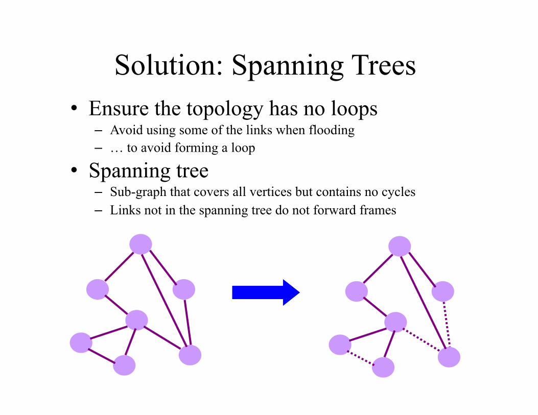
Solution: Spanning Trees • Ensure the topology has no loops
– Avoid using some of the links when flooding – … to avoid forming a loop
• Spanning tree – Sub-graph that covers all vertices but contains no cycles – Links not in the spanning tree do not forward frames

Constructing a Spanning Tree • Need a distributed algorithm
– Switches cooperate to build the spanning tree – … and adapt automatically when failures occur
• Key ingredients of the algorithm – Switches need to elect a “root”
• The switch with the smallest identifier – Each switch identifies if its interface
is on the shortest path from the root • And exclude it from the tree if not
– Messages (Y, d, X) • From node X • Claiming Y is the root • And the distance is d
root!
One hop!
Three hops!

Steps in Spanning Tree Algorithm • Initially, each switch thinks it is the root
– Switch sends a message out every interface – … identifying itself as the root with distance 0 – Example: switch X announces (X, 0, X)
• Switches update their view of the root – Upon receiving a message, check the root ID – If the new id is smaller, start viewing that switch as root
• Switches compute their distance from the root – Add 1 to the distance received from a neighbor – Identify interfaces not on a shortest path to the root – … and exclude them from the spanning tree

Example From Switch #4’s Viewpoint
• Switch #4 thinks it is the root – Sends (4, 0, 4) message to 2 and 7
• Then, switch #4 hears from #2 – Receives (2, 0, 2) message from 2 – … and thinks that #2 is the root – And realizes it is just one hop
away • Then, switch #4 hears from #7
– Receives (2, 1, 7) from 7 – And realizes this is a longer path – So, prefers its own one-hop path – And removes 4-7 link from the
tree
1!
2!
3!
4!
5!
6!7!

Example From Switch #4’s Viewpoint
• Switch #2 hears about switch #1 – Switch 2 hears (1, 1, 3) from 3 – Switch 2 starts treating 1 as root – And sends (1, 2, 2) to neighbors
• Switch #4 hears from switch #2 – Switch 4 starts treating 1 as root – And sends (1, 3, 4) to neighbors
• Switch #4 hears from switch #7 – Switch 4 receives (1, 3, 7) from 7 – And realizes this is a longer path – So, prefers its own three-hop path – And removes 4-7 link from the tree
1!
2!
3!
4!
5!
6!7!

Robust Spanning Tree Algorithm • Algorithm must react to failures
– Failure of the root node • Need to elect a new root, with the next lowest identifier
– Failure of other switches and links • Need to re-compute the spanning tree
• Root switch continues sending messages – Periodically re-announcing itself as the root (1, 0, 1) – Other switches continue forwarding messages
• Detecting failures through timeout (soft state!) – Switch waits to hear from others – Eventually times out and claims to be the root
See Section 3.2.2 in the textbook for details and another example!

Evolution Toward Virtual LANs • In the olden days…
– Thick cables snaked through cable ducts in buildings – Every computer they passed was plugged in – All people in adjacent offices were put on the same LAN – Independent of whether they belonged together or not
• More recently… – Hubs and switches changed all that – Every office connected to central wiring closets – Often multiple LANs (k hubs) connected by switches – Flexibility in mapping offices to different LANs
Group users based on organizational structure, rather than the physical layout of the building.!

Why Group by Organizational Structure? • Security
– Ethernet is a shared medium – Any interface card can be put into “promiscuous” mode – … and get a copy of all of the traffic (e.g., midterm exam) – So, isolating traffic on separate LANs improves security
• Load – Some LAN segments are more heavily used than others – E.g., researchers running experiments get out of hand – … can saturate their own segment and not the others – Plus, there may be natural locality of communication – E.g., traffic between people in the same research group

People Move, and Roles Change • Organizational changes are frequent
– E.g., faculty office becomes a grad-student office – E.g., graduate student becomes a faculty member
• Physical rewiring is a major pain – Requires unplugging the cable from one port – … and plugging it into another – … and hoping the cable is long enough to reach – … and hoping you don’t make a mistake
• Would like to “rewire” the building in software – The resulting concept is a Virtual LAN (VLAN)

Example: Two Virtual LANs
Red VLAN and Orange VLAN!Bridges forward traffic as needed!
R!RO! RO!
O!RO!

Example: Two Virtual LANs
Red VLAN and Orange VLAN!Switches forward traffic as needed!
R!
O!RO!
R!
R!
R!
O!O!O!R! O!R! R! R!O!
O!O!

Making VLANs Work • Bridges/switches need configuration tables
– Saying which VLANs are accessible via which interfaces • Approaches to mapping to VLANs
– Each interface has a VLAN color • Only works if all hosts on same segment belong to same VLAN
– Each MAC address has a VLAN color • Useful when hosts on same segment belong to different VLANs • Useful when hosts move from one physical location to another
• Changing the Ethernet header – Adding a field for a VLAN tag – Implemented on the bridges/switches – … but can still interoperate with old Ethernet cards

Moving From Switches to Routers
• Advantages of switches over routers – Plug-and-play – Fast filtering and forwarding of frames – No pronunciation ambiguity (e.g., “rooter” vs. “rowter”)
• Disadvantages of switches over routers – Topology is restricted to a spanning tree – Large networks require large ARP tables – Broadcast storms can cause the network to collapse

Addressing

Topics • IP addresses
– Dotted-quad notation – IP prefixes for aggregation
• Address allocation – Classful addresses – Classless InterDomain Routing (CIDR) – Growth in the number of prefixes over time
• Packet forwarding – Forwarding tables – Longest-prefix match forwarding – Where forwarding tables come from

IP Address (IPv4)
• A unique 32-bit number (i.e., 4B addresses) • Identifies an interface (on a host, on a router,
…) • Represented in dotted-quad notation
00001100 00100010 10011110 00000101
12 34 158 5

Grouping Related Hosts
• The Internet is an “INTER-NETwork” – Connects networks together, not hosts – Addresses a network (i.e., group of hosts)
host! host! host!
LAN 1!
...! host! host! host!
LAN 2!
...!
router! router! router!WAN! WAN!
LAN = Local Area Network!WAN = Wide Area Network!
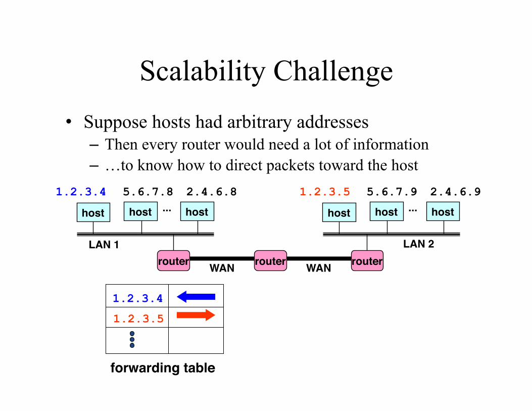
Scalability Challenge • Suppose hosts had arbitrary addresses
– Then every router would need a lot of information – …to know how to direct packets toward the host
host! host! host!
LAN 1!
...! host! host! host!
LAN 2!
...!
router! router! router!WAN! WAN!
1.2.3.4 5.6.7.8 2.4.6.8 1.2.3.5 5.6.7.9 2.4.6.9
1.2.3.4
1.2.3.5
forwarding table!

Hierarchical Addressing: IP Prefixes
• Divided into network & host portions (left and right)
• 12.34.158.0/24 is a 24-bit prefix with 28 addresses
00001100 00100010 10011110 00000101
Network (24 bits) Host (8 bits)
12 34 158 5
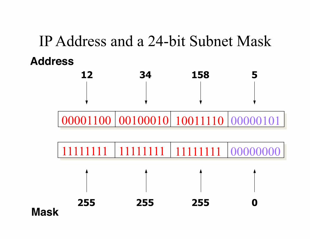
IP Address and a 24-bit Subnet Mask
00001100 00100010 10011110 00000101
12 34 158 5
11111111 11111111 11111111 00000000
255 255 255 0
Address!
Mask!

Scalability Improved • Number related hosts from a common subnet
– 1.2.3.0/24 on the left LAN – 5.6.7.0/24 on the right LAN
host! host! host!
LAN 1!
...! host! host! host!
LAN 2!
...!
router! router! router!WAN! WAN!
1.2.3.4 1.2.3.7 1.2.3.156 5.6.7.8 5.6.7.9 5.6.7.212
1.2.3.0/24
5.6.7.0/24
forwarding table!

Easy to Add New Hosts • No need to update the routers
– E.g., adding a new host 5.6.7.213 on the right – Doesn’t require adding a new forwarding entry
host! host! host!
LAN 1!
...! host! host! host!
LAN 2!
...!
router! router! router!WAN! WAN!
1.2.3.4 1.2.3.7 1.2.3.156 5.6.7.8 5.6.7.9 5.6.7.212
1.2.3.0/24
5.6.7.0/24
forwarding table!
host!
5.6.7.213

Address Allocation

Classful Addressing • In the olden days, only fixed allocation sizes
– Class A: 0* • Very large /8 blocks (e.g., MIT has 18.0.0.0/8)
– Class B: 10* • Large /16 blocks (e.g,. CSU has 129.82.0.0/16)
– Class C: 110* • Small /24 blocks (e.g., AT&T Labs has 192.20.225.0/24)
– Class D: 1110* • Multicast groups
– Class E: 11110* • Reserved for future use
• This is why folks use dotted-quad notation!
Classless Inter-Domain Routing (CIDR)
33
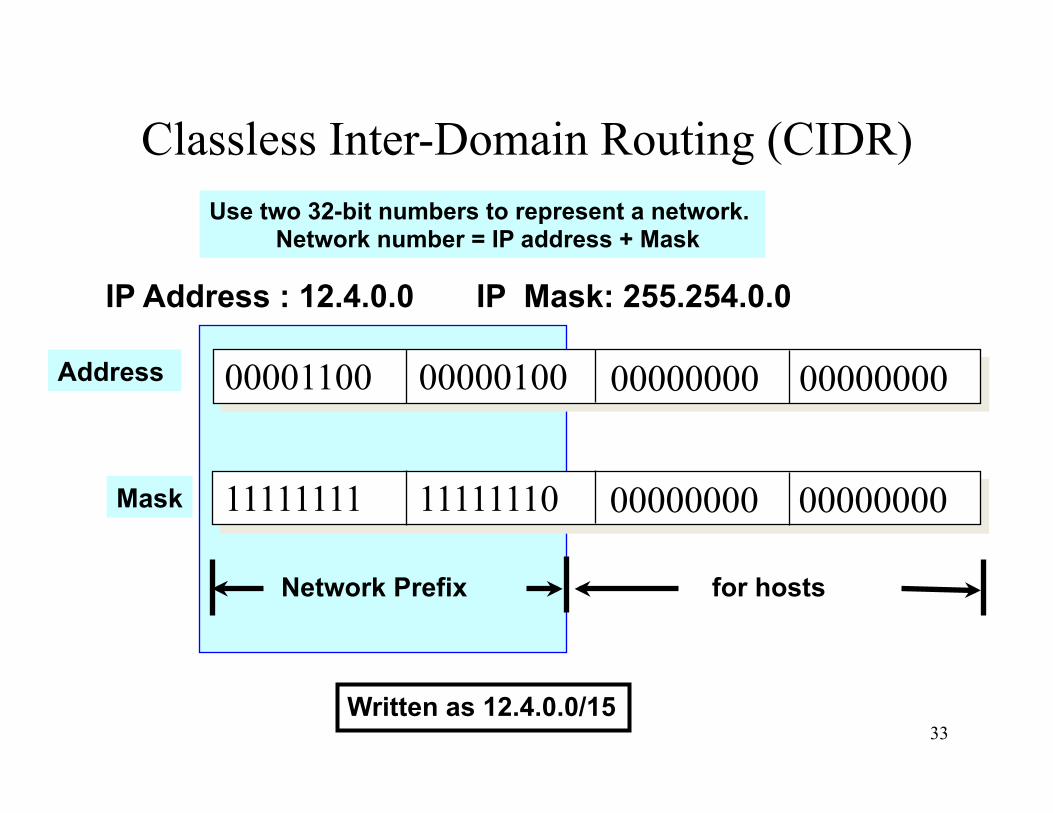
IP Address : 12.4.0.0 IP Mask: 255.254.0.0
00001100 00000100 00000000 00000000
11111111 11111110 00000000 00000000
Address
Mask
for hosts Network Prefix
Use two 32-bit numbers to represent a network. Network number = IP address + Mask
Written as 12.4.0.0/15
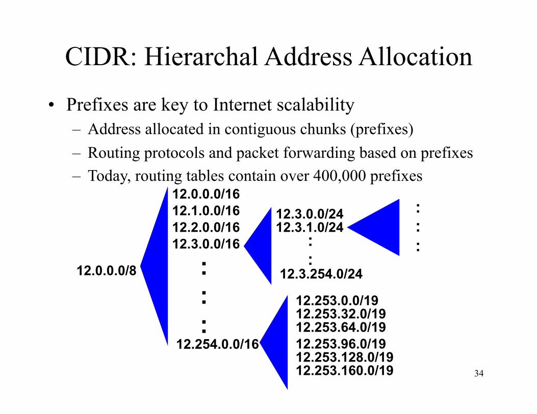
CIDR: Hierarchal Address Allocation
34
12.0.0.0/8
12.0.0.0/16
12.254.0.0/16
12.1.0.0/16 12.2.0.0/16 12.3.0.0/16
: : :
12.3.0.0/24 12.3.1.0/24
: :
12.3.254.0/24
12.253.0.0/19 12.253.32.0/19 12.253.64.0/19 12.253.96.0/19 12.253.128.0/19 12.253.160.0/19
: : :
• Prefixes are key to Internet scalability – Address allocated in contiguous chunks (prefixes) – Routing protocols and packet forwarding based on prefixes – Today, routing tables contain over 400,000 prefixes

Scalability: Address Aggregation
Provider is given 201.10.0.0/21
201.10.0.0/22 201.10.4.0/24 201.10.5.0/24 201.10.6.0/23
Provider
Routers in the rest of the Internet just need to know how to reach 201.10.0.0/21. The provider can direct the
IP packets to the appropriate customer.!
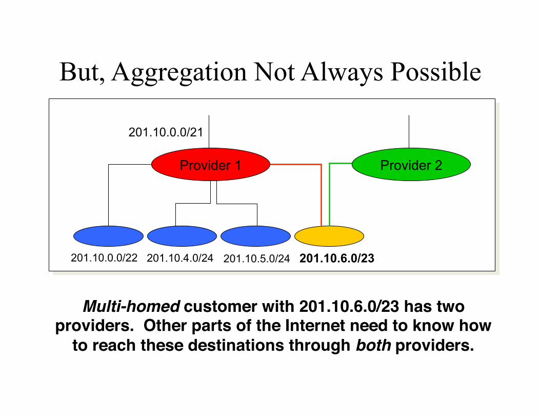
But, Aggregation Not Always Possible
201.10.0.0/21
201.10.0.0/22 201.10.4.0/24 201.10.5.0/24 201.10.6.0/23
Provider 1 Provider 2
Multi-homed customer with 201.10.6.0/23 has two providers. Other parts of the Internet need to know how
to reach these destinations through both providers.!

Scalability Through Hierarchy • Hierarchical addressing
– Critical for scalable system – Don’t require everyone to know everyone else – Reduces amount of updating when something changes
• Non-uniform hierarchy – Useful for heterogeneous networks of different sizes – Initial class-based addressing was far too coarse – Classless Inter Domain Routing (CIDR) helps
• Next few slides – History of the number of globally-visible prefixes – Plots are # of prefixes vs. time
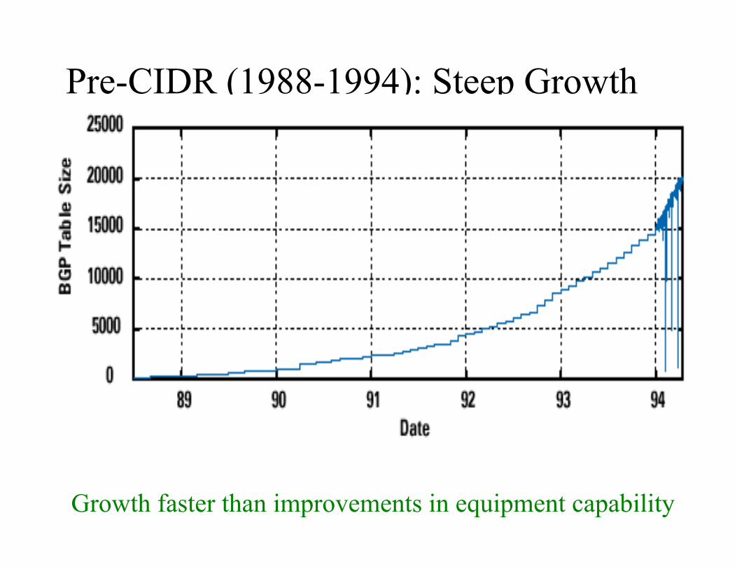
Pre-CIDR (1988-1994): Steep Growth
Growth faster than improvements in equipment capability

CIDR Deployed (1994-1996): Much Flatter
Efforts to aggregate (even decreases after IETF meetings!)

CIDR Growth (1996-1998): Roughly Linear
Good use of aggregation, and peer pressure in CIDR report

Boom Period (1998-2001): Steep Growth
Internet boom and increased multi-homing
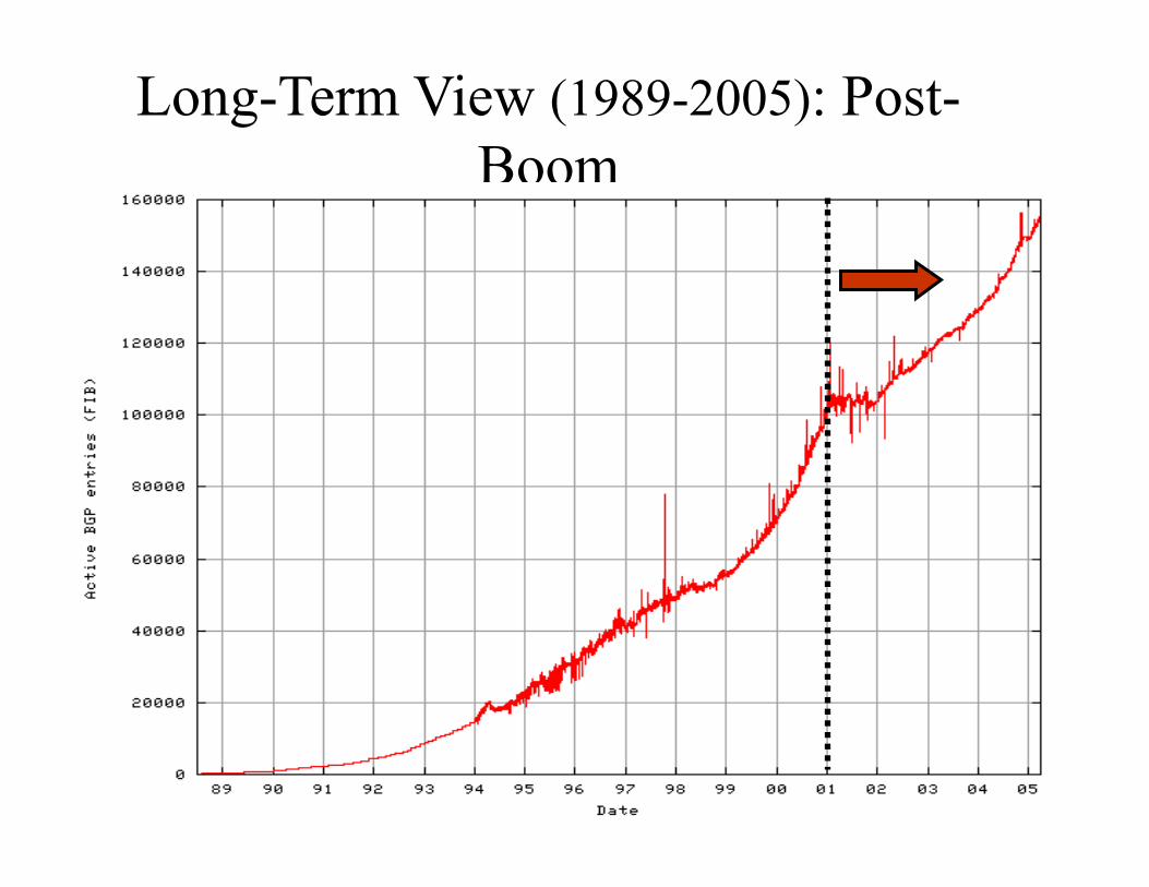
Long-Term View (1989-2005): Post-Boom

Obtaining a Block of Addresses • Separation of control
– Prefix: assigned to an institution – Addresses: assigned by the institution to their nodes
• Who assigns prefixes? – Internet Corporation for Assigned Names and Numbers
• Allocates large address blocks to Regional Internet Registries
– Regional Internet Registries (RIRs) • E.g., ARIN (American Registry for Internet
Numbers) • Allocates address blocks within their regions • Allocated to Internet Service Providers and large
institutions – Internet Service Providers (ISPs)
• Allocate address blocks to their customers • Who may, in turn, allocate to their customers…

Figuring Out Who Owns an Address
• Address registries – Public record of address allocations – Internet Service Providers (ISPs) should update
when giving addresses to customers – However, records are notoriously out-of-date
• Ways to query – UNIX: “whois –h whois.arin.net 128.112.136.35” – http://www.arin.net/whois/ – http://www.geektools.com/whois.php – …

Example Output for 128.112.136.35 OrgName: Princeton University OrgID: PRNU Address: Office of Information Technology Address: 87 Prospect Avenue City: Princeton StateProv: NJ PostalCode: 08544-2007 Country: US NetRange: 128.112.0.0 - 128.112.255.255 CIDR: 128.112.0.0/16 NetName: PRINCETON NetHandle: NET-128-112-0-0-1 Parent: NET-128-0-0-0-0 NetType: Direct Allocation RegDate: 1986-02-24

Are 32-bit Addresses Enough? • Not all that many unique addresses
– 232 = 4,294,967,296 (just over four billion) – Plus, some are reserved for special purposes – And, addresses are allocated in larger blocks
• And, many devices need IP addresses – Computers, PDAs, routers, tanks, toasters, …
• Long-term solution: a larger address space – IPv6 has 128-bit addresses (2128 = 3.403 × 1038)
• Short-term solutions: limping along with IPv4 – Private addresses – Network address translation (NAT) – Dynamically-assigned addresses (DHCP)

Hard Policy Questions • How much address space per geographic region?
– Equal amount per country? – Proportional to the population? – What about addresses already allocated?
• Address space portability? – Keep your address block when you change providers? – Pro: avoid having to renumber your equipment – Con: reduces the effectiveness of address aggregation
• Keeping the address registries up to date? – What about mergers and acquisitions? – Delegation of address blocks to customers? – As a result, the registries are horribly out of date