Packaging with Styropor - BASF EPS Construction...
39
Packaging with Styropor ® BASF Plastics key to your success
Transcript of Packaging with Styropor - BASF EPS Construction...

Packag ing wi th S ty ropor ®
BASF Plasticskey to your success


3
Packaging with Styropor®
4 This is Styropor®
DevelopmentThe Styropor® range
5 From Styropor® to the finished foamPreexpansionIntermediate agingMolding
6 ProcessingModel makingElastificationPrintingPaintingCoatingLabeling
78 PropertiesFoam properties of relevance for packagingFood regulations
13 Packaging requirementsEase of moldingMany types of packagingPackages and closuresPackaging and sales promotionProtection against impact and stackingChecklist for packaging designStructural reinforcement
20 Shock absorptionDesign of cushioningDesign recommendations
26 Compressive strengthDesign of packs for load-bearing applicationsDesign recommendations
29 Thermal insulationDesign of thermally insulating packagingDesign recommendations
32 Packages and their contentsTest methods and regulationsCost-effectiveness
36 Recycling and disposalRecycling in foam productionProduction of Styromull®Recycling in PS processing Energy recoveringRecycling in the construction industryRaw materials recyclingLandfill
Fig. 1:Packaging line fortelevision sets ® = Registered trademark of BASF Aktiengesellschaft

4
This is Styropor®
Styropor® has made a name for itself –as a packaging material too. In com-bination with economical moldingprocesses, the special advantagesoffered by Styropor® are used all overthe world to protect packaged goods. The versatility of Styropor® was recognized early on. For engineers,packaging experts and designers, its possible applications are by nomeans exhausted. There are still manyopportunities to be gained by usingthis high-performance, low-cost foam.This brochure will tell you all aboutpackaging with Styropor®, while at thesame time stimulating new ideas andfurther development possibilities.
Development
The first styrene synthesis was carriedout by BASF in Ludwigshafen in 1929.Only a year later, in 1930, polystyrenewas already being produced on anindustrial scale, but it took another 20 years before it proved possible tomake polystyrene foam. On August14, 1952 the German Patent Officepublished “Method of making porousmasses from polymers” and thismarked the beginning of Styropor®.
Styrene, which forms the molecularbuilding block for Styropor®, and pen-tane, which is used as blowing agentin the production of Styropor® foam,are both obtained from petroleum and are therefore pure hydrocarboncompounds from which expandablepolystyrene is obtained through suspension polymerization.
The Styropor® range
The various grades currently availableare summarized below. Detaileddescriptions of commercial andexperimental products can be foundin our technical data sheets.
Styropor® PUsed for making blocks, boards andmolded parts.
Styropor® FFlame-retardant materials recom-mended for making flameresistantblocks and boards in accordance withDIN 4102, as well as molded partscomplying with the requirements ofGroup F 1 according to DIN 53 438,Part 3.
Neopor®
Products with flame retardant treat-ment (see Styropor® F). Expandedfoams made from Neopor® are silverygray in color and have enhanced thermal insulation properties.
Peripor®
Products with flame retardant treat-ment (see Styropor® F). Expandedfoams made from Peripor® have particularly low levels of waterabsorption.
Styropor®, Neopor® and Peripor®
are expandable polystyrenes madeby BASF. They are made in the formof beadlike granules 0.2 – 3.0 mm(0.007 – 0.12 in.) in diameter andsupplied in this form to foam manu-facturers.
Fig. 2:Size comparison betweenthe raw material and thepreexpanded Styropor®
Fig. 3:Increase in volume whenStyropor® is preexpanded

5
From Styropor® to the finished foam
Styropor® is converted into blocksand moulded parts in three stages:• preexpansion, • intermediate aging and • molding.
Preexpansion
The raw material is heated to about80°C to 110°C (176°F to 230°F) inspecial foaming units, using steam.During this process the apparentdensity of the material drops fromabout 630 kg / m3 (39 pcf) to about10 kg / m3 (0.625 pcf), depending onthe temperature and residence time.To make packages and other kinds of mouldings, Styropor® is normallypreexpanded to 18 – 30 kg / m3
(1.12 – 1.87 pcf).
Prefoaming converts the compactStyropor® beads into foam beads withsmall, closed cells.
Intermediate aging
As the freshly foamed particles cooldown, blowing agent and steam tendto condense inside the cells produc-ing a vacuum which has to be equal-ized by air diffusing into the cells. Thisimparts greater mechanical stability to the beads, as well as extra foamingpower, which is advantageous for further processing. This process takesplace during intermediate aging inventilated silos. At the same time, itgives the beads an opportunity to dry.
Fig. 4:Continuous prefoaming unit
Fig. 5:Molding of prefoamedbeads
Molding
The cavity of the foaming mold, whichis usually in two parts, is now filledpneumatically with the prefoamedmaterial. The mold walls are equippedwith holes or slits to connect the moldcavity to the steam chamber. Foammolding is accomplished by the use ofsteam to supply the necessary energy.
A surge of steam causes the beads to soften again and to expand. Theexpansion pressure compresses thebeads and, at the same time, forcesthem against the mold walls so thatthey fuse together.
The resultant part is then cooled byspraying water onto the mold and by applying a vacuum. When it hascooled down sufficiently, the moldedpart can be taken from the mold.
This technique can be used to makelarge blocks, boards and moldings of almost any shape or size.

6
Processing
Styropor® foams can be machinedusing the methods normally used forwoodwork, e.g. sawing, milling andcutting. It is also possible to cutsheets and simple shapes from blocksusing heated and/or vibrating wires.This is a particularly economical wayof working, and is used to make insu-lating panels and packages requiredin only small quantities. Models for awide range of applications can bemade in the same way, e. g. prototypepacks, displays and teaching aids, artobjects, decorations, etc.
Model making
Models for many different types ofpackages and packaging applicationscan be made quickly and cheaply fromStyropor® foam. Since the material is so easy to fabricate, models andpatterns can be altered bit by bit untila pack for that is ready testing isobtained.
Fig. 6:Cutting foam with aheated wire
Elastification
The elasticity of Styropor® foams canbe increased as follows:
– by pressing it inside the mold orincreasing its volume during thefoaming process
– by pressing or rolling the finishedsheets.

7
Printing
Styropor® foams can be printed byany of the established methods.Molded parts with a raised design caneasily be printed with inked rollers.
There is one golden rule which mustalways be observed whatever theprinting technique used: printing inksmust never contain solvents whichmight attack the foam. The consis-tency and drying properties of printinginks will depend on what method ofprinting is used.
Painting
Moldings made from Styropor® can bepainted without any problem. Paintingcan enhance mechanical strength andimprove weathering resistance. It canalso increase the material’s watervapor diffusion resistance and inden-tation resistance. Paints can obviouslyalso be used to achieve special deco-rative, colored and gloss effects.
Here, too, it is important that paintsused for application by dipping, rollingand spraying must under no circum-stances attack the material. For thisreason, only paints specifically formu-lated for use on polystyrene materialsshould be used.
Coating
Flexible as well as hard coatings forfoams can be formulated with poly-urethanes, depending on the particu-lar formulation. These can be appliedin one or several operations, depend-ing on the required thickness.
Solvent-free epoxy resins can beapplied directly to the foam, but poly-ester resins require previous applica-tion of a solvent-proof barrier coat.Glass fiber mats can be incorporatedin the coating material to make itimpact resistant.
Electrostatic flocking of the moldedparts opens up interesting designpossibilities. Parts can also be coveredwith films, etc.
Transfers, cold and hot bonding labelscan likewise be applied to foam usinghand operated, semiautomatic or fully automatic machines. The kind ofadhesive used will be determined bythe chemical nature of the foam
A coating technique specially recom-mended for large-scale productioninvolves combinations with films (Fig.19. page 15), sheets or moldingsmade from solid plastics, as well aswith paper and cardboard. These can all be laminated immediately afterthe completion of foam molding, in adownstream unit or, after the moldedpart has been allowed to age for awhile, in a special coating unit.
Labeling
Packages made of Styropor® are labeled in accordance withDIN 55 471, Part 1.
A standard name looks something like this:
Foam DIN 55 471 – EPS 20 B – F.
This means:
DIN 55 471 – EPS = type of material: EPS foam (expand-able polystyrene), foam molded.
20 = density = 20 kg / m3 tolerance: ± 2.5 kg / m3
B = degree of drying: residual moisture content < 0.1% byvolume.
F = fire characteristics (free of silicones);requirements of Group F 1 accordingto DIN 53 438, Part 3, are fulfilled.
N.B.: In view of the recyclability of Styropor® packaging under the“single grade, clean and dry” slogan,it is advisable to make sparing use of printing ink and coatings.

8
The physical properties of the materialare influenced by its apparent densityand how it has been processed.
Foam properties of relevance for packaging
A tabular compilation of the mostimportant properties of Styropor®
foams is presented in the appendix to the brochure.
Compressive stress according toEN 826The compressive strength of mate-rials which undergo elastic or plasticdeformation when a force is applied,is essentially governed by the degreeof compression. In the case of rigidfoams, therefore, it is usual to indicatethe compressive stress at 10% com-pression, !d10 (see Fig. 10) in order to obtain comparable figures.
The compressive strength ofStyropor® foams increases withincreasing density (Fig. 7).
For test pieces with an outer skin thevalues of compressive stress will beslightly lower than for cut specimenshaving the same density. This is dueto the fact that the density is unevenlydistributed across the test piecethickness: near the edges it is higherthan at the center. The applicationadvantage of a smooth, slightly com-pacted outer skin is therefore notmade apparent when testing accord-ing to EN 826.
Tensile strength according to EN 1608 The tensile strength of Styropor®
foams increases with increasing den-sitiy, as shown in figure 8. Elongationat break, determined in tensile tests,is among the properties that are alsodependent on processing conditions,e. g. on fusion quality.
Flexural strength according to EN 12089 The flexural strength, too, increaseswith increasing apparent density, asshown in figure 9. The material’sdeflection at break (toughness)decreases with increasing density and degree of fusion.
Fig. 7:Effect of density on compressive stressat 10 % compression (EN 826) (scatter rangeindicated)
Fig. 8:Effect of density on tensile strength (EN 1608)
Fig. 9:Effect of densityon flexural strength (EN 12089)
Com
pres
sive
stre
ss (k
Pa)
Gross density (kg/m3)
600
500
400
300
200
100
0 5 10 15 20 25 30 35 40 45 50 55 60 65
Mean Value
Shea
r stre
ngth
(kPa
)
Gross density (kg/m3)
1000
500
400
300
200
100
0 5 10 15 20 25 30 35 40 45 50 55 60 65
600
700
800
900
Mean Value
Flex
ural
stre
ngth
(kPa
)
Gross density (kg/m3)
1000
500
400
300
200
100
0 5 10 15 20 25 30 35 40 45 50 55 60 65
600
700
800
900
Mean Value
Properties
9
Com
pres
sive
stre
ss (k
Pa)
Strain (%)
600
500
400
300
200
100
010 20 30 40 50 60 70 80
Design ranges for impact-damping products
Design ranges for productsdesigned to withstandcompressive stress
EN 826
Density 30 kg/m3
20 kg/m3
optimalrangeoptimalrange St
rain
(%)
Duration of loading (d)
4.0
3.5
3.0
2.5
2.0
1.5
1.0
0.5
0 100 200 300 400 500 600
70 kPa
60 kPa
30 kPa
Density: 20 kg/m3 Load
Stra
in (%
)
Duration of loading (d)
4.0
3.5
3.0
2.5
2.0
1.5
1.0
0.5
0 100 200 300 400 500 600
140 kPa
100 kPa
60 kPa
Density: 30 kg/m3 Load
Stra
in (%
)
Density (kg/m3)
4.0
3.5
3.0
2.5
2.0
1.5
1.0
0.5
0 14 16 18 20 22 24 26 28 30 32
500 Days
100 Days
1 Minute
Dependence on apparent density after different periods
of strain:60 kPa
Fig. 11:Relationship of longtermloading of Styropor®
foams to density aftervarious durations of loading
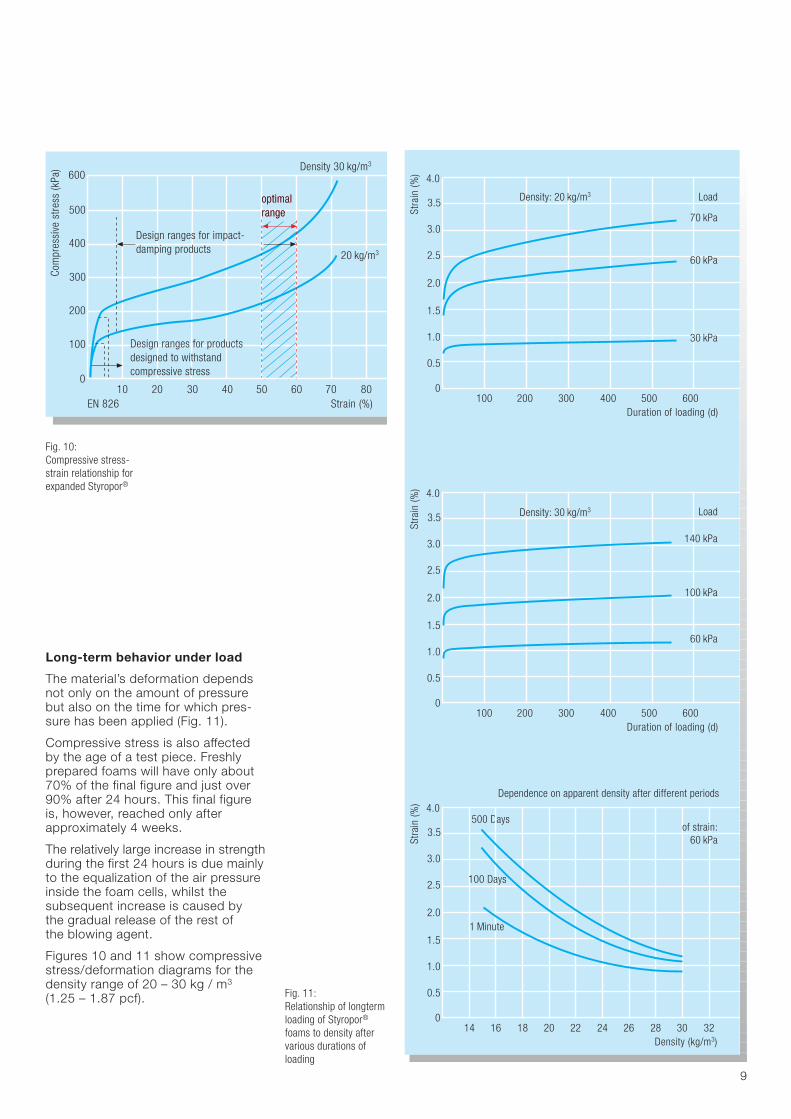
Long-term behavior under load
The material’s deformation dependsnot only on the amount of pressurebut also on the time for which pres-sure has been applied (Fig. 11).
Compressive stress is also affected by the age of a test piece. Freshlyprepared foams will have only about70% of the final figure and just over90% after 24 hours. This final figureis, however, reached only after approximately 4 weeks.
The relatively large increase in strengthduring the first 24 hours is due mainlyto the equalization of the air pressureinside the foam cells, whilst the subsequent increase is caused by the gradual release of the rest of the blowing agent.
Figures 10 and 11 show compressivestress/deformation diagrams for thedensity range of 20 – 30 kg / m3
(1.25 – 1.87 pcf).
Fig. 10:Compressive stress-strain relationship forexpanded Styropor®

10
Thermal properties
The mechanical properties of thematerial depend on temperature. Figure 12 shows how the compressivestress at 10% compression changesin the temperature range of –20°C to + 60°C (4 to 140°F).
Styropor® foams are noted for theirparticularly low thermal conductivity.This is dependent on the density and on the temperature of the foam(Table 3, page 30), as well as on its moisture content.
The specific heat capacity ofStyropor® foams is not influenced bytheir density. In the bulk density range20 – 30 kg/m3, the resistance to heatdeformation according to EN 826 andEN 1605 is only dependent to a smallextent on the bulk density (see table 5).The freshly made foam attains its finalheat distortion properties only afteraging. Foams not under stress willwithstand temperatures of up to about100°C for short periods, independentof their density. (e. g. bonding with hotbitumen).
The coefficient of thermal expansion is unaffected by density and is around5 – 7·10-5 K-1.
The mechanical properties ofStyropor® foams are uneffected by their moisture content or byatmospheric humidity.
Water absorption and water vaporpermeability
Styropor® foams are not hygroscopicbut will absorb moisture if broughtinto direct contact with water.
If there are different water vapor con-centrations on two sides of a piece offoam, water vapor will tend to diffusethrough the foam. This phenomenonis particularly evident if there is a tem-perature gradient. To characterizewater vapor diffusion use is made ofthe diffusion resistance factor µ, com-pared with a stationary layer of airhaving the same thickness (µ = 1).This factor depends on the foam’sdensity.
Chan
ge in
com
pres
sive
stre
ngth
(%)
Temperature
40
20
10
±0
-10
-30
-40-20 ±0 20 40 °C 60
-20
30
4 32 68 104 °F 140Fig. 12:Effect of temperature
Electrical properties
Styropor® foam does not conductelectricity. The dielectric constant ! forfoams with densities of between 20and 40 kg / m3 (1.25 and 2.50 pcf) is 1.02 – 1.04 between 100 Hz and400 MHz. The dissipation factor tan " up to 1 MHz is less than 0.0005 and up to 400 MHz 0.00003. The specificdielectric strength reaches values of 2 kV / mm. The resistivity at 23°C(73°F) and 50% relative humidity is 1014 – 1016 " (IEC 60093).
Because of the high surface resis-tance, an electrostatic charge canbuild up on the surface of some foamcomponents – especially if the atmos-pheric humidity is low. The surfaceresistance of moldings can bereduced by adding an antistatic agentduring the manufacturing process.
Chemical resistance(see table 1, page 11)
Styropor® P, F, Neopor® and Peripor®
behave exactly like polystyrene in thepresence of chemical agents. Chemi-cals which attack polystyrene willdestroy Styropor® foam more quicklythan the solid material, because of thethin-walled cells of which it is made.This means that low density foams willbe attacked more intensely. Styropor®
is unaffected by water, most acidsand alkali solutions.
Essential oils contained in the peeland juice of citrus fruit will attack Styropor®, but the material is resistantto animal and vegetable fats as wellas to anticorrosive agents containingparaffins, as long as they do not contain aggressive solvents.
The material’s sensitivity towardsorganic solvents should, above all, be noted in painting and adhesivebonding. The same applies to contactwith plastics containing plasticizers,e. g. plasticizer migration in the caseof PVC.
If Styropor®, Neopor® or Peripor®
have to be brought into contact withsubstances of unknown composition,the reaction of the material shouldfirst be checked. The best way ofdoing this is by immersing a piece ofStyropor® in the other material andobserve what happens. The durationof the experiment can be reduced byraising the temperature of immersion.

11
Effect of UV light
Styropor® foams, like other plasticmaterials, are affected by UV light ifthey are exposed to it for prolongedperiods. As far as packaging is con-cerned however, this is of very minorimportance, bearing in mind the tran-sient nature of packaging.
Biological effects
Pentane escapes from Styropor®
during storage and fabrication. Espe-cially when the foams are being cutwith heated wires, measures must be taken to ensure extraction of theresulting vapors, as they contain small amounts of styrene as well aspentane.
The MAK (maximum allowable con-centration) for styrene and for pentaneshould be observed (for details seeTechnical Information “Expanded Styropor® and the Environment”).
Styropor® foams are not food for animals. Styropor® foams do not rot,are insoluble in water and do not giveoff any water-soluble substanceswhich could pollute groundwater.Foam waste can be tipped on landfillsites along with ordinary householdrubbish under observance of localbyelaws.
Styropor® foam has now been in pro-duction for several decades, duringwhich time no risk to health has beenfound.
Fire characteristics
Like many other packaging materials,Styropor® foam is flammable. Its firecharacteristics depend not only on the actual material but also on theconditions under which it is used. The material’s fire behavior is largelydependent upon other materials withwhich it is used and the protectivecoatings that are often necessary.
A distinction must be made betweenproducts without flame retardanttreatment such as the Styropor® Pgrades (referred to as P grades inwhat follows) and products with flameretardant treatment such as the Styropor® F grades, Peripor® andNeopor® (referred to as F gradesbelow).
Table 1: Chemical resistance of Styropor® foams
Chemical or Solvent Styropor® P and F
Salt solution (seawater) +
Soaps and wetting agent solutions +
Bleaching agent solutions, e. g. sodium hypochlorite, +chlorine water and hydrogen peroxide
Dilute acids +
Hydrochloric acid, 35%; nitric acid up to 50% +
Anhydrous acids, e.g. fuming sulfuric acid, –100% formic acid
Caustic soda and caustic potash solutions, ammonia water +
Organic solvents, such as acetone, ethyl acetate, benzene, –xylene, paint thinners and trichloroethylene
Saturated aliphatic hydrocarbons, surgical spirit, –white spirit
Paraffin oil, vaseline +/–
Diesel fuel –
Motor fuels (regular and super grade gasoline) –
Alcohols, e.g. methanol, ethanol +/–
Silicone oil +
+ resistant: the foam is not attacked even after a long time+/– limited resistance: the foam may shrink after prolonged exposure to the chemical, or its surface may be attacked– not resistant: the foam shrivels up more or less quickly or is dissolved
F grades are classified as “flame retar-dant”. This means that the foam’sflammability and flame spread alongthe surface have been much reduced.F grades therefore achieve the bestpossible classification for flammablesubstances according to variousnational specifications for building and other materials.
The fire behavior of foam packagesmade from P grades follows much the same pattern as that of otherflammable packaging materials. F grades are being used more andmore to increase fire safety. This, incidentally, is taken into account byinsurance companies in drawing upfire insurance agreements.

12
Food regulations
BfR, the German Federal Institute forRisk Assessment, publishes recom-mendations in the German FederalHealth Bulletin (Bundesgesundheits-blatt) under the Law on Food andCommodities.
These recommendations specify,according to the current state ofknowledge, under which conditions a consumer article made from highpolymer materials will meet therequirements laid down in the 1974regulations covering foodstuffs andconsumer goods.
The monomer used to produce Styropor®, namely styrene, complieswith Directive 2002/72/EC and islisted in the new version of the German Ordinance on Materials andArticles of 12/23/1997, including the latest changes of 04/07/2003.
We recommend our Styropor® Pmoldings and block products for themanufacture of food packaging. Theprocessing and production aids alsoused in their manufacture are listed in appropriate BfR recommendationsfor polymers that contain polystyrene.
Provided the material is processedcorrectly, there is no objection to itsuse in the production of consumergoods intended for food contactapplications and for toys. The suita-bility of consumer articles for anygiven purpose must be checked bythe manufacturer as well as the user.
The important proviso is this: packaging materials used for food-stuffs must in no way affect their taste or aroma. It is up to the firmdoing the packaging to check thatthis requirement is met.
Practical experience has shown thatthere is no problem in this respect, if the Styropor® packaging materialshave been stored for some time. Theexception is specially aroma-sensitiveand fat-based products such aschocolate, margarine or cream cakes.Here it is best to use some sort ofwrapping material like parchmentpaper, plastic film or aluminum foil.
Fig. 13:Styropor® foam boxesfor transporting foods

13
Packaging requirements
The purpose of packages is to pro-tect their contents on their way fromthe manufacturer to the consumer.Packaging ranges from simple insertsto complex display packs, made in all shapes and sizes. They have anenormously wide range of uses in alarge number of industries and formany different types of products.Their main functions can be summa-rized as follows:
• protection during transport andstorage
• production of standard and transportable units
• sales promotion with informativeand publicity function.
Compared with traditional packagingmaterials such as wood, cardboard,paper, metal and glass, and theequally traditional crates, boxes, bags,wrappers, cans, tubes and bottles,plastics have proved to be the idealpackaging materials in many differentfields. Plastics can cope with practi-cally any kind of packaging problem.They are economical to use and showbetter adaptibility than many of theclassic packaging materials.
Because of its excellent physical andchemical properties, Styropor® foamoffers the following advantages whenused as a packaging material:
• Iow density, therefore lightweightpackages
• high energy absorption whendropped or subjected to impact –cushioning for protecting delicateitems during transport and storagecan therefore be relatively thin
• abrasion-resistant yet relatively softsurfaces protect packaged goodsagainst dirt and damage
• Iow thermal conductivity protectscontents against sudden tempera-ture changes
• since the foam is unaffected bywater and water vapor, its mechani-cal properties remain intact
• chemically inert, so that it can beused for food packaging
• easy to mold into almost any shapewhich helps the packaging designer.
Ease of molding
Foam components can be made inalmost any shape for a wide range of packaging applications using thesimplest and most economical means.Here are some examples:
• protection against outside influences(outer containers and coverings)
• anti-impact cushioning to preventhigh acceleration during impact,when dropped or shaken or ex-posed to vibration
• impact and stress distributors whichevenly distribute mechanical forcesacross the whole loadbearing surface
• inserts and supports which preventmovement of the goods inside thepack (made of pieces of foam,molded parts).
Rigidity, light weight, smooth, softsurfaces, good chemical compatibilitywith packaged contents – these arethe properties which have made Styropor® foam such a successfulmaterial in this field. The main condi-tion is always that the package hasbeen correctly designed and con-structed for the intended application.It is particularly here that Styropor®
users have the advantage because of the ease with which the materialcan be shaped and molded.
Fig. 14:Packaging inserts forsensitive goods

14
Many types of packaging
The main uses of Styropor® packagesare described below.
• Packaging inserts These are molded parts or insertsused as shock absorbers, to distrib-ute loads, to support the contentsor to keep them separate. There arealso sorting and assembly insertsand pallets for use in storage andin-house transport containers.
• Box-type packs With customized inside space: individual portion packs, partitionedpacks and packs which protect thecontents against heat.
• Composite moldings Where a particular packaging problem cannot be solved by usingfoam on its own, one can combine it with another material to form acomposite, because Styropor®
foam can supplement or enhancethe properties of traditional materialssuch as paper, cardboard, corru-gated cardboard, wood and plastic.Such composite packs, made fromStyropor® foam and other materialshave, for example, been success-fully used for packaging heavy items,and for gift and display packs.
• Crates and trays for foodstuffsThese are used for fish, fruit andvegetables.
• Transport and display pallets
Fig. 15:Tray for transportingfood – compression resistant and reusable
Fig. 16:Thermally Insulatingpacks for fresh fish
15
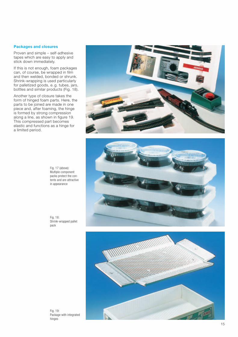
Packages and closures
Proven and simple – self-adhesivetapes which are easy to apply andstick down immediately.
If this is not enough, foam packagescan, of course, be wrapped in filmand then welded, bonded or shrunk.Shrink-wrapping is used particularlyfor palletized goods, e. g. tubes, jars,bottles and similar products (Fig. 18).
Another type of closure takes the form of hinged foam parts. Here, theparts to be joined are made in onepiece and, after foaming, the hinge is formed by strong compressionalong a line, as shown in figure 19.This compressed part becomes elastic and functions as a hinge for a limited period.
Fig. 18:Shrink-wrapped palletpack
Fig. 19:Package with integratedhinges
Fig. 17 (above):Multiple componentpacks protect the con-tents and are attractivein appearance

16
Foam packages can also be equippedwith interlocking closures. This isachieved by producing clawlikeundercuts, which are difficult to tearapart (Fig. 20).
Packs can also be combined with car-rying handles, e. g. with plastic strapswhich go around the pack, straps withjointed studs or with wooden carryinghandles which can be slid into thepack (Fig. 23).
Fig. 20:Packaging for hydrantswith interlocking mechanism
Fig. 21:Packaging for firehydrants.Second use:installation in the ground as protectionagainst frost and to promote drainage

17
Packaging and sales promotion
Styropor® foam is also used for pub-licity and sales promotion packaging,since it can be molded into almostany shape. Decorative effects are easily achieved by printing, coatingand electrostatic flock spraying.
Small numbers of individual productsdo not necessarily mean high packag-ing costs. It is possible, for example,to design one uniform pack for differ-ently shaped items. The number ofitems increases and packaging costsdrop – and, nevertheless, one stillgets a made-to-measure pack. Theonly condition is that the inside isdesigned in such a way that all theproducts of a particular range can beaccommodated.
Styropor® sales packs can also bemade so that they can be divided intosmaller units which may be requiredby the retail trade. This is achieved by incorporating artificially weak linesalong which the pack can easily bebroken off.
In many cases it is possible to solve aparticular problem very economically,also in combination with other materi-als. A typical example is foam used to protect the edges of packages,incorporating integral or subsequentlybonded strips of wood, chipboard, orhardboard. Combinations with paperor cardboard also offer interestingalternatives in many instances.
Fig. 22:Combination pack
Fig. 23:Carrying handle toensure safe transport
Fig. 24:Multiple-componentpacks sales for anattractive appearance

18
Protection against impact andstacking
Much care is necessary in designingand constructing foamed packagingunits if these have to be stacked orare intended for delicate articles sen-sitive to impact. As the deformationdiagram (Fig. 10, page 9) shows, themechanical properties of Styropor®
foams enable these to be used forload-bearing applications as well asfor cushioning materials. Here, thedesired function is governed by thelevel of the applied load.
The deformation curves in figure 10show that Styropor® foams show verylittle deformation at compressivestresses up to about 100 – 200 kPa (14 psi – 29 psi). This stress range isexploited for compression-resistantpackages.
If the foam is subjected to larger loadsit will become deformed and act like a cushion. Optimum use of thesedeformation characteristics can bemade at deformations of 50 – 60%.
The following sections deal not onlywith the more general aspects ofmolded Styropor® packs but also withthe dimensioning and construction ofcompression-resistant and shockab-sorbent packages. Finally the calcula-tion of thermal insulation of Styropor®
foam packs is explained and illustratedwith various examples.
Checklist for packaging design
First of all we must define all the conditions to which a packaging container is exposed and thedemands made on the package.These include, for example:
– inside dimensions and contours (... how must the item inside besupported – does it have to beenclosed all round?)
– stackability of the packs (... how high will the stacks be, howgreat the stacking pressure and dostacking aids have to be taken intoaccount?)
– protection against impact (... how delicate is the item beingpackaged – what maximum dropheights can be expected duringtransport?)
– protection against heat and cold (... what temperatures will the goodswithstand – how high are the ambi-ent temperatures and how long willthe package be in transit?)
– strength of the pack (... what are the expected storageand transport conditions – and istransport by sea or on land?)
– special conditions (... are the packaged goods delicateor perishable?)
Fig. 25:Shrink-wrapped foampack

19
Structural reinforcements
The strength of Styropor® moldingscan be increased not only by using a higher density material but also bymeans of certain structural measures.
One can, for example, make the wallsthicker. Reinforcing ribs, protrusionsand similar elements can also beincorporated. Reinforcing ribs, unlikethe ribs used for cushioning purposes,are made semicircular so as to mini-mize the risk of mechanical damage.
The example of packaging for anengine block illustrates the interplay of these factors (Fig. 26).
Fig. 26:All-round pack for carengines
Fig. 27:Packs with side cushionsto protect the contentsagainst impact
– also to be considered is the stream-lining of packaging and transporta-tion: putting the items into the packmust be made easy; external pack-age dimensions must be in line withmethods of stacking and transport;loaded pallets should fit comfortablyinto the transit containers; if thereare several parts these should beclearly arranged; one should be ableto close packs quickly; storage andtransport units should be stream-lined; packs should be attractivelydesigned and produced to promotesales; all requirements on the part of trade and consumers should betaken into consideration.
Other factors of major importance forthe packaging manufacturer are lotsize, density, dimensions and permis-sible tolerances.
The design of a package is thereforedetermined by external influences, the type of goods being packaged aswell as economic considerations.

20
Shock absoption
Fig. 28:Multi-unit pack for television picture tubes
One of the most important functionsof a package is to protect an articleagainst damage when it is dropped orsubjected to impact. This is achievedby the deformation of the cushioningelements, which reduces the forcesacting on the unit. The various influ-encing factors and our design recom-mendations are described in the following pages.
In order to raise a body with a weightof m to a certain height h the energyrequired is given by E = (m · g) h.When the body drops down fromheight h, this energy is released again.The magnitude of the force acting onthe body will depend on the brakingdistance and the time needed to bringthe body to a halt.

21
Cushion thickness
Defo
rmat
ion
forc
e ~
Impa
ct a
ccel
erat
ion
0.5.d 0.6•d 1•d
2.5
1.0
0
Ideal cushion
ExpandedStyropor® foam
E
E
(1) An ideal cushion deforms completely under the stress of a fall (d = 0); the impact accelerationduring deformation of the cushion is constant in this case until the position of rest is reached.
(2) E0 = E1 = m •g •h = m •b •d; from this it follows that b / g = h / db / g = impact acceleration (impact factor or G value) as a multiple of the acceleration due to gravity.
h=height of fall
d=cushion thickness
g=acceleration due to gravity
Ideal cushion
b=impact acceleration
weight = m • g
energy E0 = m • g • h
energy E1 = m• b • d
deformation force = m •b = m •(h / d) •g
Packaged material(mass m)
Packaged material(mass m)
Fig. 29:Ideal and real cushioning model
a) Illustration of characteristic parameters with reference to the example of an ideal cushion
Figure 29 a shows that the maximumforce acting on an ideally cushionedbody, i.e. in the theoretically mostfavorable case, is given by the expres-sion h / d·(m · g).
but rather at Styropor® foams satisfythese conditions particularly well com-pared with other cushioning materials.As the force-deformation diagram(Fig. 29 b) shows, the deformationresistance of Styropor® foam buildsup very quickly and changes relativelylittle up to about 60% deformation. In correctly dimensioned packs thisleads to exceptionally low G values.
Real cushions behave less favorablythan ideal cushions. The reason forthis is the change in deformation forceas the cushion deforms, especially athigh deformations. Accordingly thebest shock-absorbing properties areobtained not at complete, deforma-tions of 50 to 60%.
The requirements for a good cushion-ing material can be derived from figure 29 b:
• increase in deformation resistanceto a specific value for a short deformation distance
• as constant a deformation resis-tance as possible over the greatestpossible deformation distance.
b) Comparison of ideal cushion with Styropor® foam under optimumloading
The variation factor h / d relative to the force acting on the body at rest is referred to as the impact factor G,or the G value deformation,

22
Fig.30:Deformation and recovery of cushioningribs
Design of cushioning
The damping capacity of a cushioningmaterial is influenced not only by itsspecial characteristics but also by theloads to which it is subjected. Thisbehavior is illustrated in figure 32,using as an example a person divinginto water from a spring board:
• In the case of a “belly flop” thedepth of immersion, i.e. the brakingdistance, is at a minimum. The divernotices that a relatively great force is acting on his body.
• In the case of a head-first dive, theforce acting on the body will initiallybe at a minimum. Water here actsas a cushioning material and brakesthe body but only slowly. At the endof the cushioning material there isabrupt damping with a great deal offorce acting on the person’s head,which is the impact surface.
• The most favorable behavior occursat a very specific diving angle. Here,the body uses the available cushion-ing distance to achieve even braking.The resultant braking forces and G values are at their lowest in thiscase.
If there are any changes in the originalconditions, e. g. if the height of thediving board, or the diver’s weight, orthe depth of the water are different –then the diving angle will also have to be different if the body is to be subjected to a minimum load. If theratio of diving board height to depthof water (h / d) increases, a smallerdiving angle will have to be chosen(greater load acting on the body) inorder to convert the diving energywithin the available diving distance.

23
max
imum
load
act
ing
on b
ody
durin
g di
ving
h2 =5md =2m
hd( = 2.5)
static surface load = body weight / impact area
low
low medium high
high
mediumh1 =3md =2m(h
d =1.5)
h2
h1
d
Fig. 32:Cushion model: –“Diving from a spring-board”
Fig. 31:Recesses enable thispack to be used forseveral automobile window panes

24
When a package is dropped, similarevents are observed. The cushioningproperties can be matched to require-ments by judicious choice of foamdensity and package dimensions.
Extensive trials have been carried out to determine the foam’s dampingproperties for different loads, cushionthicknesses, drop heights and densities.The results were converted into cush-ioning curves which are recommendedin DIN 55471, Part 2, as a basis fordimensioning foam packages.
The characteristics given in the dia-grams have the following significance:
Impact factor G = G value (this is thefactor by which the actual weight ofthe packaged item increases duringimpact). The maximum permissible Gvalue for any given packaged article iscalled the “packaged item sensitivity”.
The adjoining examples show howcushioning diagrams can be used for dimensioning Styropor® foam cushioning elements.
drop high in cmcushion thickness in cm
h =d
Static surface load
weight of packaged item in Ncontact area in cm2
impa
ct fa
ctor
G
static surface load ! in N/cm2
160
140
120
100
80
60
40
20
00 0.2 0.4 0.6 0.8 1.0 1.2 1.4 1.6 1.8 2.0 2.2 2.4
40
35
30
26
2220
1816
1412108642
h = drop heightd cushion thickness
28
24
Example 1
Example 2
Fig. 33:Cushion diagram forfoams made of EPS 20
Influencing factors Units load for optimum cushioning
example 1 example 2
Weight of packaged goods (m) kg 10 10
Cushion area (A) cm2 ? ?
Cushion thickness (d) cm ? 4.2
Drop height (h) cm 90 100
Impact factor G – 70 ?(Sensitivity of packaged goods) (G)
Fig. 34:Calculation examplewith the aid of the cushioning diagram for20 kg/m3 (1.25 pcf)foam
Example 1 required: A und d(load for optimum cushioning) from cushion diagram:
known: RD = 20 kg / m3 h / d = 28m = 10 kg != 0.51 N / cm2
m · g = 98.1 N1)
h = 90 cmG = 70
Calculations:
Example 2 required: A und G(load for optimum cushioning) from cushion diagram:
known: RD = 20 kg / m3 G = 60m = 10 kg (m · g = 98.1 N) ! = 0.62 N / cm2
d = 4.2 cmh = 100 cm Calculations:
h / d = 24
d = h(h / d)
90 cm28= = 3.2 cm
A = m · g!
98.1 N0.62 N / cm2= = 158 cm2
A = m · g!
98.1 N0.51 N/cm2
= = 192 cm2
=
1 kg · ms2
1)1N =
9.81 ms2m · g = 1 kg · = 9.81 N
The weight of a 1 kg mass is given by:

25
Fig. 35:Guidelines for correct rib design
Fig. 36:Different designs forshock-absorbent packs
Apart from cushioning diagrams thereis a simple to use “BASF dimensioncalculator” for determining optimumcushion thickness and surface area.The basis for dimensioning cushioningelements is formed by the minima of the cushioning curves (Fig. 33).One cannot therefore obtain structural values differing from optimum figuresby this method.
The calculated cushion surface areasare, in most cases, smaller than thesurface available to support the pack-aged item. This must therefore becompensated by appropriate packag-ing design. In the case of ribs andknobs, the following should be noted:
• ribs and knobs, and the depths of the cavities into which they fitshould take up between 50 and60% of the calculated total cushionthickness;
• where ribs and knobs are incor-porated, the calculated cushionthickness should be increased by a factor of 1.1;
• the cushioning area is taken to bethe area at the mean rib height;
• the flank angle of ribs and knobsshould be about 10 to 15° and theroot radii about 10 mm (0.40 in.).
Design recommendations
Packaging calculations provide infor-mation about required cushion thick-nesses, cushion surface areas andfoam densities. This information hasto be converted into a suitably shapedpackage, with due consideration of all package requirements. The mostcommon kinds of packaging areshown in figure 36. The special fea-tures of these packs are as follows.
• Design No. 1 has smooth outside surfaces and is ribbed on the inside. All that isneeded here is adhesive tape orsleeves made of plastics film orcardboard to seal the pack.
• Design No. 2 enables the packaged item to fitsnugly into the pack. Ribbed on theoutside, this type of pack ensuresthat the article inside is securelyfixed and will withstand even theseverest knocks during transit.
• Design No. 3 is a partial pack with two side shellsor top and bottom shells. This typeof pack is particularly suitable as ashock absorber and is normallyplaced inside a cardboard or corru-gated cardboard box.
• Design No. 4 shows edge and corner protectorswhich are used especially for furni-ture and large units. In addition,they are used as general purposeprotectors against impact.
full-wrap pack withribs on the inside1
2 full-wrap pack withribs on the outside
side cushioningelements3
corner cushioningelements4
A
I
b #
rdRH/2
H

26
Compressive strength
Styropor® foams are classified as rigidfoams in accordance with DIN 7726.They therefore combine maximumcompressive stress with low deforma-tion. It is very easy to influence thecompressive stress values by meansof density. Molded packaging units –including self-supporting packs aswell as inserts – can therefore be eco-nomically produced.
The most widely used combinationpacks consist of collapsible corru-gated cardboard boxes with Styropor®
foam inserts. Maximum use is thusmade of a foldable outer box com-bined with foam-molded cushioninginserts.
Figure 39 demonstrates the greatcontribution made by Styropor®
foam inserts towards increasing thecompression resistance of collapsible corrugated cardboard boxes. This is even more evident under dampconditions because even direct contact with water will not affect the foam’s strength in any way.
Fig. 37:Compression resistantpackaging for refrigera-tors

27
Design of packs for load-bearingapplications
The compressive stress deformationcurves shown in figure 10, page 9,were obtained in tests with a constantrate of deformation in accordancewith EN 826. Under actual practicalconditions, however, packages aresubjected to entirely different kinds of stress, such as long-term anddynamic stresses – and this is why the compressive stress figureswe have given cannot be used for dimensioning packages.
Figures that can be used in the designof packs are specified in DIN 55471,Part 2. These enable the designer tocalculate the permitted loads to whichStyropor® foam packs can be sub-jected, using the following equation:
#d $Fmax
A
#d permissible compressive stressin N/mm2
Fmax maximum stress in NA surface area under stress
in mm2
The important point to note is that thefigures given in the standard referredto above are maximum permissiblecompressive stresses at a standardtemperature and humidity of 20°C (68°F) and 65% respectively accord-ing to DIN 50014. If temperatures arehigher, lower compressive stresseswill have to be laid down (Fig. 12).
Force-deformation diagram: Test piecesa.collapsible, corrugated cardboard box (2.7)
L x W x H = 32 x 29 x 28 cm(12.6 x 11.4 x 11.0 in)
b.collapsible, corrugated cardboard box (2.7)L x W x H = 32 x 29 x 28 cm(12.6 x 11.4 x 11.0 in) d = 9 cm (3.5 in)with two Styropor® foam side shells of density20 kg/m3.
force (N)
deformation (%)
3000
2000
1000
01 2 3 4
100 %
40 %a
b
F
Styropor®
B+C vertical forces, therefore no dangerousnotch stresses
A risk of breakage due to excessively highnotch stresses
recesses with large radii
deformable stacking aidsFig. 38:Stacking aids
Fig. 39:Force-deformation diagram
Fig.40:Correctly designedstacking aids

Calculation
A Styropor® pack is to be subjected to a maximum load (Fmax) of 2000 N.What would the supporting surfacearea have to be for foams with den-sities of 20, 25 and 30 kg/m3 (1.25,1.56, and 1.87 pcf).
This is calculated using the followingequation:
Fmax % !d, max · A
Fmax = maximum stacking load
!d, max = maximum permissible compressive strength(see table 2)
A = supporting surface area (i.e.load-bearing area of foampack)
for density 20 we have:
A $ =51282 mm2 $ 513 cm2
for density 25 we have:
A $ =36364 mm2 $ 364 cm2
for density 30 we have:
A $ =28169 mm2 $ 282 cm2
28
Table 2: Permitted compressive stresses
Foam gradeand respective values
Properties EPS 20 EPS 25 EPS 30 EPS 35 EPS 45
Permitted compressive stress !d in N / mm2*– at nominal density accord- 0.039 0.055 0.071 0.087 0.119
ing to DIN 55471, Part 1
* 1 N / mm2 = 1000 kPa
Reduced contactsurfaces due to conicalouter walls
Reduced contactsurfaces due to externalradii of curvature atthe base
Optimum utilizationof support surfaces
x
x
y
y
section x–x
section y–y
section y–y
r
Design recommendations
In designing Styropor foam packs thefollowing points should be noted inaddition to ensuring that the permittedcompressive strain is adhered to:
• The load-bearing walls of the foampacks must transmit the stackingforces down to the floor verticallyand in a straight line. This is particu-lary important when designing stack-ing aids (Fig. 38/40).
• In order to obtain the maximumpossible bearing surfaces, prefer-ence should be given to rectangularouter edges and outer walls that runexactly vertical to the surface of thebase (Fig. 41).
• On the basis of experience, packag-ing elements are sufficiently rigid if the ratio of their thickness (d) toheight (h) is >0.1 (Fig. 42).
Fig. 41:Design recommen-dations for outside contours
Fig. 42:Design recommen-dations for inside corners and edges
2000 N0.055 N / mm2
2000 N0.039 N / mm2
2000 N0.071 N / mm2

29
Thermal insulation
Where goods have to be protectedfrom temperature extremes duringtransport and storage, or where theyhave to reach their destination eitherhot or cold, thermally insulating packsmust be used. This is an obviousapplication for Styropor® foams sincethe material possesses outstandingthermal insulating properties, thanksto its closed-cell foam structure consisting of microscopically small air bubbles.
A key property of thermally insulatingmaterials is their thermal conductivity.The figures for Styropor® foam –which depend on the foam densityand mean foam temperature – arelisted in table 3 and in DIN 55471,Part 2.
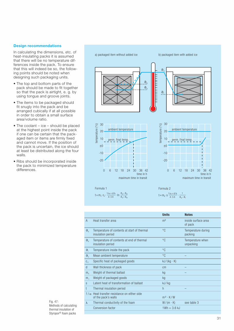
Design of thermally insulatingpackaging
From the thermal conductivity, thepack dimensions, the characteristicsof the packaged items and prevailingtemperature conditions it is possibleto calculate the time needed for a particular maximum temperature to be reached. Here one distinguishesbetween two different thermal insula-tion conditions, depending on thetemperature profile of the packagedgoods. Special mathematical relation-ships enable these to be calculated.These conditions are as follows.
• The temperature difference betweenthe packaged goods and their sur-roundings remains nearly constantfor a specific period of time, e. g. if ice is placed inside the pack (Figs. 43 and 47 b).
• The temperature difference betweenthe packaged goods and their surroundings decreases whilst thegoods are stored. This happens if no ice is placed inside the pack(Figs. 44 and 47 a).
The formulae for these calculationsare given in figure 47, page 31 and in DlN 55471, Part 2.
Fig. 44:Heat-Insulating pack for pharmaceutical preparations
Fig. 43:Safe transport of highlyperishable goods in thermally insulatingboxes made of Styropor®
foam
30
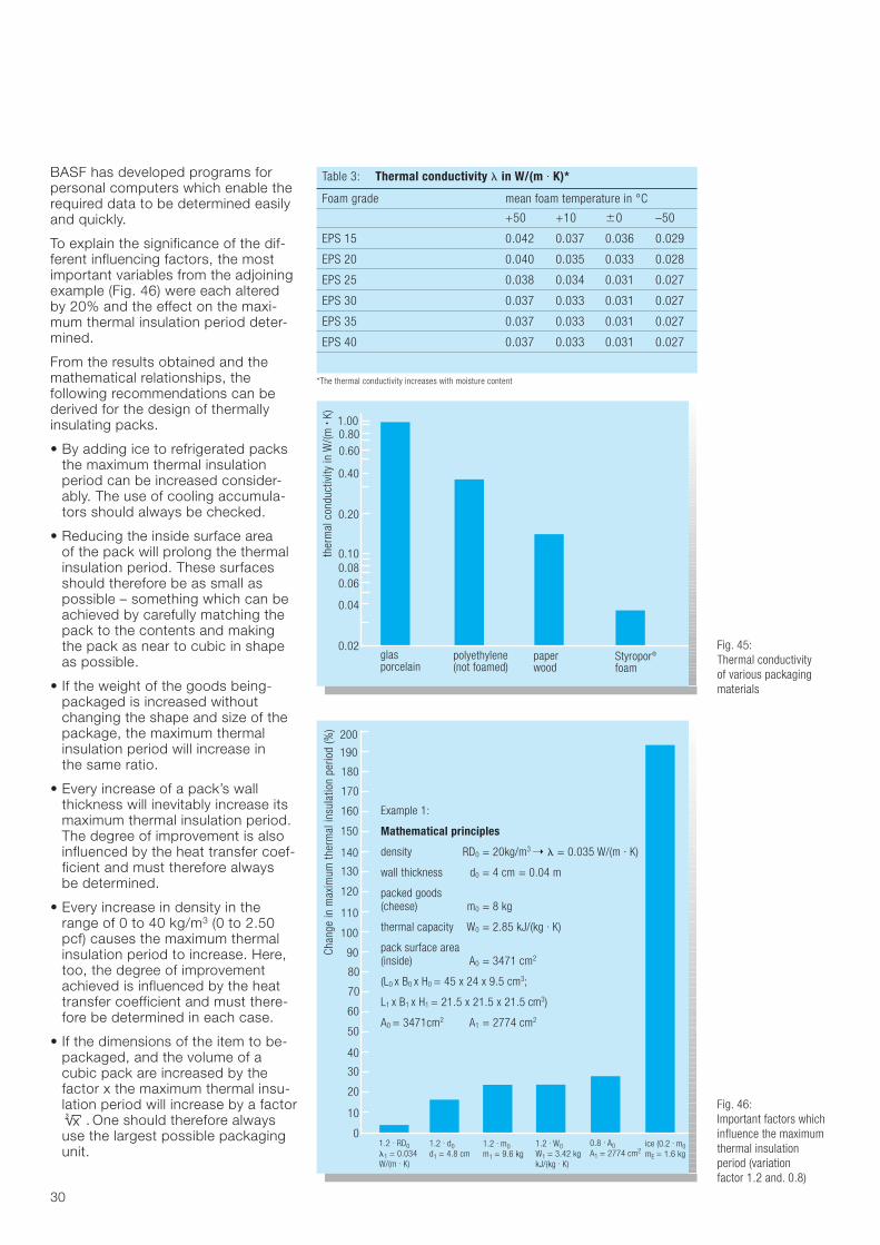
Table 3: Thermal conductivity & in W/(m · K)*
Foam grade mean foam temperature in °C
+50 +10 '0 –50
EPS 15 0.042 0.037 0.036 0.029
EPS 20 0.040 0.035 0.033 0.028
EPS 25 0.038 0.034 0.031 0.027
EPS 30 0.037 0.033 0.031 0.027
EPS 35 0.037 0.033 0.031 0.027
EPS 40 0.037 0.033 0.031 0.027
*The thermal conductivity increases with moisture content
BASF has developed programs forpersonal computers which enable therequired data to be determined easilyand quickly.
To explain the significance of the dif-ferent influencing factors, the mostimportant variables from the adjoiningexample (Fig. 46) were each alteredby 20% and the effect on the maxi-mum thermal insulation period deter-mined.
From the results obtained and themathematical relationships, the following recommendations can bederived for the design of thermallyinsulating packs.
• By adding ice to refrigerated packsthe maximum thermal insulationperiod can be increased consider-ably. The use of cooling accumula-tors should always be checked.
• Reducing the inside surface area of the pack will prolong the thermalinsulation period. These surfacesshould therefore be as small as possible – something which can beachieved by carefully matching thepack to the contents and makingthe pack as near to cubic in shapeas possible.
• If the weight of the goods being-packaged is increased withoutchanging the shape and size of thepackage, the maximum thermalinsulation period will increase in the same ratio.
• Every increase of a pack’s wallthickness will inevitably increase itsmaximum thermal insulation period.The degree of improvement is alsoinfluenced by the heat transfer coef-ficient and must therefore always be determined.
• Every increase in density in therange of 0 to 40 kg/m3 (0 to 2.50pcf) causes the maximum thermalinsulation period to increase. Here,too, the degree of improvementachieved is influenced by the heattransfer coefficient and must there-fore be determined in each case.
• If the dimensions of the item to be-packaged, and the volume of acubic pack are increased by the factor x the maximum thermal insu-lation period will increase by a factor
. One should therefore alwaysuse the largest possible packagingunit.
x3
ther
mal
con
duct
ivity
in W
/(m .
K) 1.000.80
0.40
0.20
0.100.080.06
0.04
0.02glasporcelain
0.60
Styropor®
foampaperwood
polyethylene(not foamed)
Chan
ge in
max
imum
ther
mal
insu
latio
n pe
riod
(%)
90
80
60
50
40
30
20
10
01.2 . RD0&1 = 0.034W/(m . K)
70
190
180
160
150
140
130
120
110
100
170
200
1.2 . d0d1 = 4.8 cm
1.2 . m0m1 = 9.6 kg
0.8 . A0A1 = 2774 cm2
1.2 . W0W1 = 3.42 kgkJ/(kg . K)
ice (0.2 . m0mE = 1.6 kg
Example 1:
Mathematical principles
density RD0 = 20kg/m3 ! & = 0.035 W/(m · K)
wall thickness d0 = 4 cm = 0.04 m
packed goods(cheese) m0 = 8 kg
thermal capacity W0 = 2.85 kJ/(kg . K)
pack surface area(inside) A0 = 3471 cm2
(L0 x B0 x H0 = 45 x 24 x 9.5 cm3;
L1 x B1 x H1 = 21.5 x 21.5 x 21.5 cm3)
A0 = 3471cm2 A1 = 2774 cm2
Fig. 46:Important factors whichinfluence the maximumthermal insulationperiod (variation factor 1.2 and. 0.8)
Fig. 45:Thermal conductivity of various packagingmaterials
31
Design recommendations
In calculating the dimensions, etc. ofheat-insulating packs it is assumedthat there will be no temperature dif-ferences inside the pack. To ensurethat this will indeed be so, the follow-ing points should be noted whendesigning such packaging units.
• The top and bottom parts of thepack should be made to fit togetherso that the pack is airtight, e. g. byusing tongue and groove joints.
• The items to be packaged should fit snugly into the pack and bearranged cubically if at all possible in order to obtain a small surfacearea/volume ratio.
• The coolant – ice – should be placedat the highest point inside the pack if one can be certain that the pack-aged item or items are firmly fixedand cannot move. If the position ofthe pack is uncertain, the ice shouldat least be distributed along the fourwalls.
• Ribs should be incorporated insidethe pack to minimized temperaturedifferences.
Units Notes
A Heat transfer area m2 inside surface area of pack
(a Temperature of contents at start of thermal °C Temperature during insulation period packing
(e Temperature of contents at end of thermal °C Temperature when insulation period unpacking
(i Temperature inside the pack °C
(u Mean ambient temperature °C –
c V Specific heat of packaged goods kJ / (kg · K)
d Wall thickness of pack cm –
mk Weight of thermal ballast kg –
m v Weight of packaged goods kg
s Latent heat of transformation of ballast kJ / kg
t Thermal insulation period h –
1 / # Heat transfer resistance on either side of the pack’s walls m 2 · K / W
& Thermal conductivity of the foam W / (m · K) see table 3
Conversion factor 1Wh = 3.6 kJ
Fig. 47:Methods of calculatingthermal insulation ofStyropor® foam packs
30
time in hmaximum time in transit
tem
pera
ture
(°c)
0 6 12 18 24 30 36 42
-20
-10
±0
10
20 ambient temperature
perm. final temp.
a) packaged item without added ice b) packaged item with added ice
Formula 1
t = mv· cv· · ln1/#+d/&
A · 3.6
(u– (a
(u– (e
Formula 2
t = mk· s ·1/#+d/&
A · 3.6
1
(u– (i
time in hmaximum time in transit
tem
pera
ture
(°c)
0 6 12 18 24 30 36 42
-20
-10
±0
10
20
30
ambient temperature
perm. final temp.
(e
(a
(u
(i

32
Packages and their contents
In designing a pack, the possibilitiesof adverse interactions between thepack and its contents should bechecked. These also include indirecteffects due to special environmentalconditions. The following are of special interest in this connection.
Styropor® foams do not directlyaffect other substances and materialsbecause they are high-polymer based.Blowing agent residues in the foamcan sometimes be a nuisancebecause of their smell, but they willnot directly affect the packaged contents because of the chemicalcomposition of the blowing agent and because of the extremely smallamounts of blowing agent residue.The recommendations issued by theGerman Federal Public Health Officestate that up to 2 g of blowing agentresidue per liter of foam do not repre-sent a health hazard. The actual amounts of residual blowing agentthat occur are less by about a powerof ten.
Molded Styropor® foam will permitthe passage of gases. This is anadvantage in the packaging of freshmeat and fish and other perishablefoods containing protein, since theconstant addition of oxygen preventsanaerobic microorganisms whichcause decay from developing. Thismeans that organisms such as Chlos-tridium butolinum cannot decomposethe proteins in the food, so that nofoul smell of decay is produced as isthe case with gasimpermeable packs.
The reverse effect, namely themaintenance of a certain gas atmos-phere, is important in the storage of fruit. To slow down the ripeningprocess, the fruit’s metabolic proces-ses are slowed down by increasingthe carbon dioxide content of the surrounding atmosphere. Since car-bon dioxide is formed by the fruit as a product of metabolism, it followsthat an increased CO2 concentrationwill automatically be produced in sealed foam boxes. This will dependupon the temperature, i. e. on themetabolic rate.
Fig. 48:The package material in no way affects thepack’s contents

33
Abb: 49:Wine bottle packs
Among the indirect effects is alsothe influence exerted by water whichis present in small quantities in freshlyfoamed molded parts.
Molded foam produced on modern,automatic machines will normally contain less than 0.1% by volume of residual moisture after being left for a day at room temperature. Thisextremely small amount of moisturehas no effect on most types of packaged goods. Where goods areparticularly sensitive to moisture,however, they must be protected not only against residual moisture, in the pack but also against atmos-pheric humidity. Here, polyethylenebags containing a desiccant haveproved effective.
In view of the chemical resistanceof the foam (Table 1, page 11), there is little likelihood of packaged goodsaffecting the foam pack. The onlysubstances requiring care are fats,plasticizers and organic solvents. IfStyropor® foam packaging is allowedto come into contact with plasticscontaining plasticizer or painted surfaces, they can stick together atthe points of contact. A white coatingcan also be formed due to migrationof plasticizer into the foam surfacewhich then softens and becomessticky. Most of the plasticizers con-tained in flexible PVC products willattack Styropor® foam, apart fromcertain specialty plasticizers such asthe Palamoll® range made by BASF.The people responsible for doing thepackaging do not always have anyinfluence on the choice of plasticizerand the best way of overcoming theproblem of plasticizer migration is to use interlayers of polyethylene filmor paper.
Styropor® foams will come intocontact with fats and grease, forexample, when they are used to packgreasy foods or metal parts whichhave been smeared with grease toprevent corrosion. The foam will tendto be more affected as the tempera-ture rises. Cooking fats will not, how-ever, attack the foam at normal roomtemperature, 25°C (77°F).

34
Test methods and regulations
The stresses and conditions to whicha pack is subjected vary considerablyand cannot be comprehensivelydetermined. For practical purposes it is best to find out typical criticalloads for specific storage and trans-port conditions and use these as test criteria. Only loads likely to occur during normal handling should beconsidered. Exceptional loads, e. g.those resulting from incorrect handlingor accidents should not be used ascriteria since these necessitate measures which would be totallyuneconomical. Test programs forpackages are given in DIN EN 24180-1/2, available from
– Deutsches Institut für Normung e.V.Vertrieb über:
Beuth Verlag GmbHBurggrafenstraße 610787 Berlin GermanyPhone: (0 30) 26 01– 0Fax: (0 30) 26 01–12 60Email: [email protected]
– Deutsche Post NL P ExpressDeutschlandVerpackungsprüfstelleHilbertstraße 3164295 DarmstadtGermanyPhone: (0 6151) 9 08 – 0Fax: (0 6151) 9 08 – 44 14Email: verpackungsprüfstelle@
deutschepost.de
Cost-effectiveness
Six important points must be noted incalculating costs:
• the price of a pack, including all itscomponents
• the cost of assembling, sealing,addressing and marking, includingpackaging checks
• in-plant transport costs
• shipment costs
• damage to packs and the resultantinsurance costs
• number of packs involved.
In many cases the purchase price of a pack amounts to only a fraction ofthe total packaging costs. A simplecost comparison between differentkinds of packaging is therefore insuffi-cient when calculating costs.
The receipt of goods in undamagedcondition is extremely important,especially in the case of well known,familiar brands. This, too, affectspackaging costs because the packand its contents must reach the cus-tomer as a completely intact unit. Thisis what he/she expects from a brandname and this is what he/she mustget. Careful package design is there-fore vitally important.
The cost-effectiveness of a pack mustalso be viewed against the back-ground of expensive claims. Cheappacks, which are easily damaged andthus fail to do their job properly canprove to be expensive in the long run.
Many of the requirements we havementioned can be fulfilled by usingStyropor® packs which are economicin use.
Table 4 lists the Styropor® propertieswhich have to be assessed in relationto cost in order to arrive at an objec-tive comparison of profitability.

35
Table 4: Packaging characteristics of Styropor® foams
Properties Applicational advantages and possibilities Examples/further advantages
Closed-cell characteristics Buoyancy of the air enables maximum use to be Low raw material requirementsmade of the PS cell structure. High strength andrigidity despite light weight
Presence of air inside the cells imparts cushioning Shock-absorbent packagingand thermal insulation properties to the foam thermally insulating
No absorption of moisture Waterproof molded parts
Light weight, density normally Low transport costs Advantageous for sending goods by post and by airbetween 20 and 30 kg / m3 Low and constant tare which the tare can be set on the scales. Fruit and
in many cases is negligible vegetable trays and fish boxes are easily filled
Strength depends on density but shows Packs can be designed to provide the required little variation protection and strength. This means: optimization of
the amount of material needed, protection of thepackaged goods, low breakage rate and few claims
Compressive strength Compression-resistant packs with good buckling Stackable fruit and vegetable traysresistance and stackability fish boxes
Packs for heavy items such as automobile engines and gear units, machine parts, heavy householdappliances
Definable shock-absorbing capacity Cushioning effect can be calculated, thereby Packs for electrical instruments, stereo equipment,ensuring reliable cushioning effect television sets and measuring instruments, glass
and porcelain articles and the like
Low specific cushioning factor Cushioning elements can be thin, so that cushioneditems need little space
Specific energy absorption capacity Cushioning elements require little material, excellentincreases with density protection in case of edge and corner impact
Wet strength Strength is not affected by wet or damp conditions Pallets for transporting plants, fruit andas is the case with cellulose-based packaging vegetable trays, fish boxesmaterials
Empty and full packs can be stored in the open, Savings in storage spaceprovided contents are not affected by damp
Low-temperature resistance No embrittlement at low temperatures Packs for deep-frozen goods
Thermal insulation Cold and heat insulation effect can be calculated. Packs for highly perishable foods and other& = 0,03 W / (m · K) Protection against rapid temperature changes substances sensitive to high temperatures such
ensures that packaged contents are subjected to as fish, seafood, dairy products, ice cream,minimum temperature differences deep-frozen foods, hot ready meals, pharma-
ceutical and biological preparations
Heat resistance at 80°C under Combination with shrink-wrapping film, Shrink-wrapped items,compressive stress up to 2 N / cm2 transport of hot contents transport of hot meals
Resistant to chemical with few exceptions, Prepackaging is often unnecessary Food packs, outer packaging for chemicals,dust-free, hygienic, permitted for food pharmaceutical preparations and cosmeticspackaging environment-friendly disposal
Attractive appearance Attractive presentation of goods, underlining Attractive food and display packsproduct quality
Environment-friendly Ground-down packaging waste can be recycled Soil conditioning, drainage, composting, reusein the production of block foam and molded parts.Can be reconverted into polystyrene by sintering and melting
Normal methods of disposal can be used Energy recovery by incineration

36
Recycling and disposal
In-plant Styropor® waste has, inciden-tally, always been recycled by Styropor® processors and fabricators.Now, however, used Styropor® packsare being increasingly returned to themanufacturers via dealers or throughindustrial, commercial and communalcollecting centers. This scrap caneasily be recycled by being passedinto the production cycle and con-verted into new products.
Heavily soiled packs which are unsuit-able for material recovery can be easily disposed of by incineration,composting or dumping on landfillsites.
The most important methods of recycling and disposal are describedin detail below (see also fig. 51).
Recycling in foam production
Ground, clean foam waste can, withincertain limits and for certain types of products, be reused in the foammolding of blocks etc. by adding it to the virgin material.
Production of Styromull®
Styromull® is obtained by grindingStyropor®. The size of the resultantpieces should be between 4 and 25 mm, depending on the intendeduse. Styromull® is officially recognisedas a soil conditioner which is beingsuccessfully used to improve thequality of garden soil, as an aid incompost making, as a filter medium in pipe drainage and as a filler in slitdrainage.
Recycling in PS processing
Styropor® foams can easily be con-verted back into compact polystyreneby sintering and melting techniquesinvolving the use of heated rolls,screw extruders or Diskpack plasti-cators. The resultant recycled materialmay be used for making extruded andinjection-molded parts.
Energy recovering
Styropor® foam can be incinerated in municipal and communal refuseincinerators at the usual temperaturesof about 1000°C and with an ade-quate supply of air. The foam shouldbe chopped up coarsely and mixedwith other refuse. This allows trouble-free disposal without any residues. The high energy content of foamsenables the amount of extra heatingto be reduced – 1 kg of Styropor®
saves 1.2 – 1.4 liters of fuel oil.
Recycling in the construction industry
Ground Styropor® waste is used torender bricks porous, as an additivefor insulating/lightweight plasters and for Styropor® concrete fillers and Styropor® building elements. Thisaffords products with improved ther-mal insulation and electrical propertiesand also considerable reductions inweight.
Raw materials recycling
In raw materials recycling expandedfoam waste and mixed plastics wasteare converted back to fresh chemicalraw materials which are not subject to any restrictions regarding applica-tions.
The waste material can also be usedin the production of cement and pigiron.
Landfill
The waste material should be cut up into small pieces in order to savespace, prevent the formation of airpockets in the rubbish dump and tomake compaction easier
Plastic waste is a raw material – it is ashame to send it to landfill. As statedabove, there are numerous processesavailable for making use of it. In manycompanies, reutilization of Styropor®
foams is state of the art. Landfill dis-posal will also be permissible underGerman legislation until the middle of2005. In order to save space, preventthe formation of air pockets in thedump and make compaction easier,the waste should be granulated.
It is an undisputed fact that Styropor® foam waste can be recycled or disposed of without any problem, provided the rightmethods are used.
Fig. 50:Soil improvement with Styromull®

37
Raw Material
Mechanical recycling
1
• Recycling in foamproduction
• Recycling in Constructionindustry
• Recycling inPolystyreneProcessing
• Recycling asStyromull%
2
6EPS
Collection/Used Styropor® packs Mill
Fine Grinder Dedusting
PreexpandedStyropor®
Polystyrene
Block Mold
Production of Porous Bricks
Insulating Plaster/Lightweight Plaster
Board Extrusion
Drainage
Oil/GasPower Plant
Electricity/Steam
AgglomerationPlant
Other Plastic Wastes
Mixture of Waste
Plant Substrate Soil Conditioning Composting
Automatic InjectionMolding Machine
Styropor® ConcreteGap-Filling Material
Styropor® Concrete Building Components
AutomaticMolding Machine
Energy Recovery3
Extrusion Granulation Plant
Fig. 51:Recycling of Styropor® foams
Recycling of Styropor® foams

Note
The data contained in this publicationare based on our current knowledgeand experience. In view of the manyfactors that may affect processingand application of our product, thesedata do not relieve processors from carrying out their own investiga-tions and tests; neither do these data imply any guarantee of certainproperties, nor the suitability of theproduct for a specific purpose. Anydescriptions, drawings, photographs,data, proportions, weights etc. givenherein may change without priorinformation and do not constitute the agreed contractual quality of the product. It is the responsibility of the recipient of our products toensure that any proprietary rights and existing laws and legislation areobserved. (May 2006)
38
Table 5: Physical properties of Styropor® foams for packaging
Properties 1) Test standard Unit Test result
Density DIN EN ISO 845 kg/m3 20 30
Thermal conductivity at 10 °C compression DIN 52612 mW/(m · K) 33 – 36 31 – 35
Compressive stress at 10 % compression DIN EN 826 kPa 110 – 140 200 – 250
Modulus of elasticity (pressure test) DIN EN 826 Mpa 3.5 – 4.5 7.5 – 11.0
Long-term compressive stress DIN EN 1606 kPa 25 – 40 45 – 60<1% after 50 years
Permitted compressive stressfor packaging calculations DIN 55471, Part 22 kPa 39 71
Specific cushioning factor, C* DIN 55471, Part 22 1 2.5 2.5
Specific impact resistance capacity e* DIN 55471, Part 22 kJ/m3 150 250
Flexural strength DIN EN 12089 kPa 250 – 310 430 – 490
Shear strength EN 12090 kPa 124 – 154 214 – 244
Tensile strength DIN EN 1608 kPa 230 – 330 380 – 480
Short-term resistance to heat deformation DIN 53424 °C 100 100
Long-term resistance to heat deformation DIN EN 1605 % <5 <5DLT(1)5: compression at 20 kPa/80°C/48 h)
Coefficient of linear expansion 1/K 5 – 7 · 10-5 5 – 7 · 10-5
Specific heat capacity DIN 53765 J/(kg · K) 1210 1210
Water vapor diffusion flow density3 DIN EN 12086 1 75 85
1 = Corresponding to test standard2 = DIN 55471, Part 23 = Value according to DIN 4108, Part 4

KS
EN 0
603
BE
July
200
6
BASF AktiengesellschaftStyrenic Polymers Europe67056 LudwigshafenGermanywww.styropor.com