
Packaged Terminal Air Conditioners & Heat Pumps = Upgraded kick plate standard height 2" to 6" (Like...
28
Catalog March 2007 PTAC-PRC002-EN Models PTEE and PTHE PTEE070/PTHE070 (7,000 Btuh) PTEE090/PTHE090 (9,000 Btuh) PTEE120/PTHE120 (12,000 Btuh) PTEE150/PTHE150 (15,000 Btuh) Packaged Terminal Air Conditioners & Heat Pumps
-
Upload
vuongduong -
Category
Documents
-
view
246 -
download
1
Transcript of Packaged Terminal Air Conditioners & Heat Pumps = Upgraded kick plate standard height 2" to 6" (Like...

Catalog
March 2007 PTAC-PRC002-EN
Models PTEE and PTHE
PTEE070/PTHE070 (7,000 Btuh)PTEE090/PTHE090 (9,000 Btuh)PTEE120/PTHE120 (12,000 Btuh)PTEE150/PTHE150 (15,000 Btuh)
Packaged Terminal Air Conditioners & Heat Pumps

Introduction
© 2007 American Standard Inc. All rights reserved PTAC-PRC002-EN
• Exclusive patent pending De-Humidification Control provides up to 30% more moisture removal.
• Flexible digital Interface provides wall or unit mounted control adjustment. Wall mounted Interface uses 2 unpolarized wires for connection.
• Plug and Play display means on demand commissioning algorithm and automatic start-up delay.
• The Universal Heater as a standard option means “Everything is stocked and ready to ship.”
• Defrost Control – All heat pump models are equipped with heat pump control algorithm that prevents freezing of the condenser, while optimizing comfort.
Packaged Terminal Air Conditioners & Heat Pumps
Trane Packaged Terminal Air Conditioners (PTACs) and heat pumps are ideally suited for offices, apartments, hotels, motels, dormitories and nursing homes. Key benefits which make the units a wise choice are:
Quieter equipment than ever with Sound Transmission Criteria STC of 27 and NC of 38.

PTAC-PRC002-EN 3
Packaged Terminal Air Conditioners & Heat Pumps . . . . . . . . . . . . . . . . . . . 2
Contents . . . . . . . . . . . . . . . . . . . . . . . . . . . . . . . . . . . . . . . . . . . . . . . . . . . . 3
Model Number Description . . . . . . . . . . . . . . . . . . . . . . . . . . . . . . . . . . . . . . . . . 4
Application Considerations . . . . . . . . . . . . . . . . . . . . . . . . . . . . . . . . . . . . . . . . . 7
Features and Benefits . . . . . . . . . . . . . . . . . . . . . . . . . . . . . . . . . . . . . . . . . . . . . . 8
Accessories . . . . . . . . . . . . . . . . . . . . . . . . . . . . . . . . . . . . . . . . . . . . . . . . . . . . . . .11
Performance Data . . . . . . . . . . . . . . . . . . . . . . . . . . . . . . . . . . . . . . . . . . . . . . . . . .13
Electric Power . . . . . . . . . . . . . . . . . . . . . . . . . . . . . . . . . . . . . . . . . . . . . . . . . . . . .19
Dimensions . . . . . . . . . . . . . . . . . . . . . . . . . . . . . . . . . . . . . . . . . . . . . . . . . . . . . . 21
Mechanical Specifications . . . . . . . . . . . . . . . . . . . . . . . . . . . . . . . . . . . . . . . . . 24
Warranty . . . . . . . . . . . . . . . . . . . . . . . . . . . . . . . . . . . . . . . . . . . . . . . . . . . . . . . . . 26
Contents

4 PTAC-PRC002-EN
Performance Data
Model Number Description
Each Packaged Terminal Air Conditioner/Heat Pump is assigned a multiple-character alphanumeric model number that precisely identifies each unit.
An explanation of the identification code that appears on the unit nameplate is shown below.
The model number helps owner/operator, installing contractors, and service technicians to define the operation, components and options for a specific unit.
Refer to the model number printed on the equipment nameplate when ordering replacement parts or requesting service.
P T E E 0 9 0 1 * A B 1 2 3 4 5 6 7 8 9 10 11
Digits 1, 2 – Packaged Terminal Air Conditioner
Digit 3 – Product Type
E = Air Conditioner with auxiliaryheat
H = Heat Pump
Digit 4 – Development Sequence
E = Fifth Development series
Digit 5, 6, 7 – Unit Cooling Capacity
070 = 7,000 Btu
090 = 9,000 Btu
120 = 12,000 Btu
150 = 15,000 Btu
Digit 8 — Main Power Supply
1 = 230-208V/60Hz/1phase
2 = 265V/60Hz/1phase
4 = 115V/60Hz/1phase (Hydronic Only)
Digit 9 – Electric Heat Capacity*
U = Universal heater (heater kW determined by power cord,see Accessories section)
W = Hydronic (ships with no front cover & no electric heater)
Digit 10 – Miscellaneous
A = Standard
C = Corrosion Resistant
D = Internal Condensate Pump
Digit 11 – Minor Design Sequence
The indoor fan is a cylindrical crossflowblower fan to assure an evenly distributed airflow and quiet operation
The outdoor fan consists of 5 moded plastic fan blades with slinger ring. The slinger ringremoves condensate by diffusing the water directlyonto the outdoor coil for rapid evaporation and increased cooling efficiency
Separate Condenser/Evaporator Fan MotorsTwo direct-drive permanent split capacitor two-speed motors allow for separate fan operation to increase energy efficiency and reduce noise.
The wall sleeve is acoustically and thermally insulated for quietness and increased thermal efficiency.
Filter - The nylon mesh filters slide directly out of the front panel and are completely washable for ease of maintenance.
Auto Frost Control removes ice build-up on the outdoor coil that may occur during the heat pump cycle.
Room freeze protection prevents internal room temperatures from reaching less than 40 degrees by energizing the electrical or hydronic heat.
The polycarbonate double-sloped drain pan allows for better condensate removal and promotes better indoor air quality.
The rotary compressor is mounted on rubber isolators to ensure minimal vibration and reduced operating noise.
The digital interface module has temperature indicators versus warmer/cooler settings.This diagnostic LCD is capable of displaying 8 diagnostics :Compressor FailureIndoor Temperature – No Backup AvailableIndoor Temperature – Unit Sensor Failure1Indoor Temperature – Display Sensor Failure1Indoor Coil Temperature FailureOutdoor Temperature FailureOutdoor Coil Temperature FailureConfiguration Corrupted
The vent control allows 70 to 80 cfm of fresh air to be drawn into the conditioned area.
Optional power ventdoor accessory.
Universal heater kWis determined by the power cord.

PTAC-PRC002-EN 5
Model Number Description
Table 1. Hydronic kit options
Kit Description
H = Hydronic
Coil Type
W = Water Coil
S = Steam Coil
Accessory Type
K = Kit
Power Voltage
01 = 208-230 VAC
02 = 265 VAC
04 = 115 VAC
Coil Positioning
L = Left hand hot water coil connection (Standard/Stocked)
R = Right hand hot water coil connection (Not Stocked)
Kick Plate
S = Standard 2" to 6" adjustable kick plate
E = Extended standard base kick plate 7" to 13"
M = Upgraded kick plate standard height 2" to 6" (Like the unit ventilator design)
U = Upgraded kick plate extended height 7" to 13" (Like the unit ventilator design)
Color
S = Standard Soft Dove II
C = Special Color
Figure 1. Hydronic heat option

6 PTAC-PRC002-EN
Model Number Description
Table 2. Accessories
Description Part Number
Architectural Grilles
ARCHITECTURAL ALUMINUM GRILLE BAYAAGL001
ARCHITECTURAL ALUMINUM GRILLE -DARK BRONZE
BAYAAGL002
ARCHITECTURAL ALUMINUM GRILLE - SOFT DOVE
BAYAAGL003
ARCHITECTURAL ALUMINUM GRILLE - SPECIAL COLOR
BAYAAGL004
Circuit breakers
CIRCUIT BREAKER - 208/230 15AMP BAYCBKR001
CIRCUIT BREAKER 208/230 20AMP BAYCBKR002
CIRCUIT BREAKER - 208/230 30AMP BAYCBKR003
Condensate pump
CONDENSATE PUMP 208/230 BAYCPMP001
CONDENSATE PUMP 265 BAYCPMP002
Drain Kit
DRAIN KIT BAYDRAN001
Filters
SPARE FILTERS 10 PACK BAYFLTR009
Hard Wire Kit
HARD WIRE KIT BAYHWRK001
Leveling Legs
LEVELING LEG BAYLVLG001
Power Switchi
POWER SWITCH -115V, 208/230V 265V 30 AMP BAYPSW002
Stamped grille
STAMPED ALUMINUM GRILLE - SINGLE PACK BAYSAG001
STAMPED ALUMINUM GRILLE - TEN PACK BAYSAG002
Wall Sleeve
13 INCH WALL SLEEVE BAYWSLV001
18 INCH WALL SLEEVE BAYWSLV002
24 INCH WALL SLEEVE BAYWSLV003
Power Cord
UNIVERSAL POWER CORD 115 VOLT- 15 AMP BAYPCRD007
UNIVERSAL POWER CORD 230 VOLT - 15 AMP BAYPCRD001 or BAYPCRD008
UNIVERSAL POWER CORD 230 VOLT - 20 AMP BAYPCRD002 or BAYPCRD009
UNIVERSAL POWER CORD 230 VOLT - 30 AMP BAYPCRD003
UNIVERSAL POWER CORD 265 VOLT - 15 AMP BAYPCRD004
UNIVERSAL POWER CORD 265 VOLT - 20 AMP BAYPCRD005
UNIVERSAL POWER CORD 265 VOLT - 30 AMP BAYPCRD006
Display Module
DISPLAY MODULE (TRANE LOGO STANDARD) BAYTRDM001
DISPLAY MODULE (TRANE LOGO & DEHUMIDIFICATION)
BAYTRDM002
Escutcheon Coverii
ESCUTCHEON COVER FOR FRONT PANEL (TRANE LOGO)
BAYTCVR001
Plastic Front Coveriii
PLASTIC FRONT COVER FOR PTAC BAYPCVR001
Connector for Hardwireiv
CONNECTOR FOR HARDWIRE KIT 208/230V - 15 AMP
BAYCNHK011
CONNECTOR FOR HARDWIRE KIT 208/230V - 20 AMP
BAYCNHK012
CONNECTOR FOR HARDWIRE KIT 208/230V - 30 AMP
BAYCNHK013
CONNECTOR FOR HARDWIRE KIT 265V - 15 AMP
BAYCNHK021
CONNECTOR FOR HARDWIRE KIT 265V - 20 AMP
BAYCNHK021
CONNECTOR FOR HARDWIRE KIT 265V - 30 AMP
BAYCNHK023
CONNECTOR FOR HARDWIRE KIT 115V - 15 AMP
BAYCNHK031
Subbasev vi
UNIVERSAL SUBBASE BAYSUB001
SOCKET FOR SUBBASE 208/230 20 AMP BAYSCKT001
SOCKET FOR SUBBASE 208/230 30 AMP BAYSCKT002
SOCKET FOR SUBBASE 265 20 AMP BAYSCKT003
SOCKET FOR SUBBASE 265 30AMP BAYSCKT004
i) The power switch can be installed on the hard wire junction box and provides a way to shut on and off the PTAC unit. It is an optional ac-cessory when using the power cord to power the PTAC unit. Check local codes for approval
ii) This escutcheon cover should be ordered whenever the display module is wall mounted or a thermostat or third party provider unit controls are ordered. This escutcheon includes a control cover plate that covers the normal unit mounted nomenclature. It comes 5 pieces per pack.
iii) All hydronic PTAC chassis come standard without a plastic front cover. If a unit is required to work without heat and without a hydronic kit the plastic front cover should be ordered.
iv) Not required when using a Hard Wire Kit.v) Provides a space to tie into a building’s wiring with a receptacle to plug
the unit into. It gives additional leveling and support capabilities and provides a place for fuses, a circuit breaker or a mechanical disconnect to be mounted. (30A is for units with 5kW electric heat, 20A for 3kW or less electric heat.)
vi) All subbases require a socket. For 15 and 20 amp, the 20amp socket can be used on either the 208/230V or the 265V.
Table 2. Accessories
Description Part Number

PTAC-PRC002-EN 7
NOTE: On applications not requiring subbase or leveling legs, unit may be flush mounted to floor.
Framing for wall case
Curtain wall installation
Panel and block veneer installation Optional leveling leg
Frame and brick veneer installation
Panel wall installation
Block and brick veneer installation
42 1/2” MIN.
FINISHEDFLOOR
16 1/4” MIN.
DIMENSION B
Application Considerations
Attaching wall sleeve to opening Framing with lintel

8 PTAC-PRC002-EN
Quiet Operation
Patent-pending, state-of-the-art design and construction provide a quiet environment for guests to relax. The Trane PTAC offers
• Noise Criteria of NC 38 or below
• Sound Transmission Criteria STC of 27
Energy Efficiency
Trane PTAC units and heat pumps are among the most efficient in the industry, with EERs up to 12.5 and COPs up to 3.6. The efficient design of the two direct-drive motors allow for separate indoor and outdoor fan operation to increase energy efficiency and reduce noise levels.
Packaged terminal heat pumps are an ideal choice for heating requirements in light to moderate wintry climates. Heat pumps provide a more efficient option over electric heat units by drawing 25 - 75% less wattage. Less wattage per hour directly translates to energy savings.
During heating operation, refrigerant in the heat pump runs in the reverse direction of the cooling operations. The outside air is cooled, thereby giving up heat to the refrigerant in the heat pump. This heat is then pumped back inside, resulting in up to three Btu’s of heat for every Btu of energy consumed.
During cooling operation, heat and humidity are removed from the building as the air is cooled. This heat proceeds through the compression cycle and is ultimately rejected to the outside air.
Energy-saving options available with PTAC units include:
Energy Management
Occupancy States
The controller is designed to handle two possible occupancy states:
• occupied
• occupied standby
When the Energy Management System input is present, it is possible for the controller to switch between the two occupancy states.
If the EMS input is not connected, the controller will always assume the occupied state
Occupied state
When the controller is in the occupied state, the unit runs space comfort control using the occupied setpoints. All heating/cooling/ventilation features are enabled.
Occupied Standby state
When the controller is in occupied standby state, the unit runs space comfort control using the occupied standby setpoints. All heating/cooling/ventilation features are enabled. Because the occupied standby setpoints cover a wider range than the occupied setpoints the demand for heating and cooling the space is reduced.
Temperature Setpoint Limiting
The indoor temperature setpoint buttons tell the unit how warm or cool the occupant wants the room.
The setpoint is set by pressing the up/down buttons on the interface module. These buttons do not scroll (i.e. holding the button will not continue to adjust the setpoint value) because each adjustment of the setpoint value requires its own unique button press.
Default setpoint on first power up: 72°F (22.0°C – closest approximation)
Setpoint resolution: ± 1°F (± 0.5°C)
User Mode Selection
Pressing either the snowflake or the red sun button on the unit tells the unit which mode the occupant prefers. There are four modes to choose from.
COOL
HEAT
FAN (fan only)
OFF
Fan Speed Selection
Pressing the FAN button on the interface module determines fan speed. There are two fan speeds to choose from.
LOW
HIGH
Programmable Settings
The controller has a total of seven (7) parameters that are user-configurable:
1. Vent Door Configuration
2. Indoor Fan Cycle configuration
3. Temperature Setpoint Limiting configuration
4. Energy Management Setpoint Offset configuration
5. Display Units configuration
6. Indoor Temperature Calibration
7. Dehumidfication Offset
Features and Benefits

PTAC-PRC002-EN 9
Features and Benefits
The interface module texts “SETTING” and “STEP” provide user feedback when the unit is in the configuration mode. The number directly above the word “STEP” indicates the configuration step that is being adjusted. The numbers above the word “SETTING” (XX.x) indicate the value of the parameter.
In order for the user to access the configurable parameters, a digital display module must be present.
The configuration set-up mode is entered by pressing and holding the "MODE" and "FAN" buttons simultaneously for 5 seconds.
Reliability
These features help assure reliable operation:
Room Freeze Protection
When the unit senses room temperatures of 40°F or below, the unit activates the indoor fan motor and either the electric resistance heater or the hydronic heater to help prevent pipes or fixtures from freezing. This also overrides the Energy Management System input.
Automatic Switch To Electric Heat (PTHE only)
If the room temperature falls to 2.5°F below the setpoint temperature or the unit compressor fails, the reverse cycle heat is shut off and the electric heat is turned on.
Active Defrost (PTHEs only)
The Trane PTAC has an active defrosting system that will remove any ice build-up on the outdoor coil that may occur during the heat pump cycle.
Random Restart
This function allows for the random restart of the PTAC units in the event of a power outage. The restart delay reduces the initial inrush current from the building to help prevent a second power outage caused by too much current draw.
The random restart function will occur after every power up cycle by delaying the operation of the unit for up to 90 seconds. Compressor minimum off-time is enforced after the random restart function has completed.
Compressor Restart Delay
After the compressor cycles off, it will not restart for three minutes. This feature prevents the compressor from short cycling and extends the overall life of the compressor.
Field Commissioning support
Manual Test Mode
A manual test mode is provided to allow a field technician to verify proper output and end device operation through a predetermined, timed sequence.
The sequence will automatically advance through all outputs and exit when the sequence has completed; it is left to the technician to monitor the status of the end devices during the test to verify that each operates properly.
Comfort
Dehumidification and air filtration are both factors affecting comfort.
When the air is dehumidified, occupants feel more comfortable at higher temperatures, and furniture, wall coverings, and fixtures last longer.
Trane PTAC’s patent-pending dehumidification helps maintain lower humidity levels in rooms, by as much as 30 percent without the need for expensive add-on’s.
The PTAC provides dehumidification by combining the following actions in a predefined sequence.
1. The PTAC subcools the room to a preset state, a dehumidification offset below the cooling setpoint.
2. The unit will automatically adjust the fan speed.
3. When incorporating the power vent door option, the controller will automatically adjust its position.
The hidden ventilation air intake filters outside air to reduce dust and pollen. When ventilation air is filtered, rooms stay cleaner, longer.
Attractive Digital Interface Module
Our extra-large, easy-to-read interface display exceeds others in the industry and allows guests to effortlessly manage their temperature needs.
Ease of Installation and Servicing
After the sleeve is in place, plug in or directly hard-wire the unit and it is ready to run. This PTAC has been designed to replace all industry standard wall sleeves.
With measuremenst of (13¾”D x 42”W x 16-1/16”H), Trane’s PTAC makes replacement of old or inefficient units easy and economical. This unit may also be installed flush with the outside wall.
Trane’s PTAC components are easily serviced and easy to diagnose or troubleshoot to spot potential problems.

10 PTAC-PRC002-EN
Features and Benefits
Universal Heater
The PTAC Universal Heater option is standard, and its universally sized equipment makes it available for quick delivery.
The heater’s size (kW) is determined by the type of power cord chosen for the unit. For more information see the Electric Heat Capacity table in the Performance Data section.
Room Cabinet/Front Panel
The room cabinet/front panel has a sloped discharge so that obstructions are not placed on the unit. The discharge conditioned air can be directed into the room at an angle of 15 or 40 degrees from the vertical position.
Filter
The filter is made of permanent, cleanable nylon mesh and is accessible without removing the front cover.
Condenser/Evaporator Fans
Each fan has a direct drive, two-speed motor with permanent split capacitors to provide quieter operation and increased energy efficiency.
Cooling Condensate Removal
The unit has a condensate removal system for high humidity conditions. The system includes a slinger ring which diffuses water directly on to the outdoor condenser coil for rapid evaporation and increased cooling efficiency.
Compressor
The rotary compressor is permanently mounted on rubber isolators. It’s not necessary to remove or adjust the hold down bolts during installation.
Outside Air Damper/Vent Control
The vent control allows 70 CFM (7000 and 9000 BTU models) or 80 CFM (12,000 and 15,000 BTU models) of fresh air to be drawn into the room when the indoor fan is operating
.
Filtered Outdoor Air Intake
The outdoor air intake includes a polypropylene filter that reduces the amount of dust coming into the room.
Corrosion-Resistant Chassis (Optional)
The condenser coil is painted using cathodic electrocoat. The bottom 1/3 of the compressor is coated with a water borne resin. The outdoor side of interior parts are top coated, and the base pan is cathodic electrocoated.
Vent door lever
Vent door
Unit Controls
The Digital Interface Module can be wall- or unit-mounted. The wall-mounted interface uses a 2-wire connection and is not polarized, making it nearly impossible to misconnect.
Temperature Setpoint Buttons
The indoor temperature setpoint buttons tell the unit how warm or cool the occupant wants the room.
The setpoint is set by pressing the up/down buttons on the interface module.
Drain Pan
The polycarbonate, double-sloped drain pan insures proper condensate removal and promotes better indoor air quality.
Cleanable Discharge Deck
Designed with service in mind, the discharge deck is easily accessible for cleaning purposes.

PTAC-PRC002-EN 11
Wall Sleeves
The wall sleeve is insulated on the top and sides and will fit all Trane PTAC units. Wall sleeves are an industry standard size of 13¾”D x 42”W x 16-1/16”H.
In order to allow for early installation during construction, wall sleeves are available to ship separately.
Extended Wall Sleeves
Extended wall sleeves are industry standard size of 18”D x 42”W x 16-1/16”H or 24” D x 42”W x 16-1/16”H.
Outdoor Grilles
Outdoor grilles option include: a stamped aluminum grille with vertical louvers, an anodized aluminum horizontal louver architectural grille, and a horizontal louver architectural grille painted in a soft dove, dark bronze or a special color.
Grilles can be provided in any special color. A third party company will closely match your color of choice.
Leveling Legs Kit
Leveling legs attach easily to the wall sleeve for support and accurate unit leveling on units without subbases. Adjustable from 2 5/8” to 5¼”.
Subbases
The subbase kit includes two leveling legs for sleeve support and accurate unit leveling during installation.
The subbase provides an enclosure for an electrical receptacle, power disconnect switch, and circuit breaker. Electrical connections to the building power supply wires are made inside the subbase behind the wiring access cover on the left side.
The subbase also provides structural support for the wall sleeve and the weight of the PTAC. It may be installed either before or after wall sleeve installation.
Power Switch
An optional 230/208V or 265V power switch assembly kit can be installed in a full length subbase or in the junction box of the Hard Wire Junction Box kit. The switch provides a POWER ON/OFF function as required by some electrical codes. A replacement junction box cover plate is provided with each switch.
Circuit Breaker Kit
The Circuit Breaker Kit is available in 15, 20 and 30 amp for 230/208-volt units. Check local codes for use of the circuit breaker, both for circuit protection and as a means of disconnect.
Hard-Wire Junction Box and Connector Kits
The Trane PTAC can be powered a hard wire kit.
The hard wire kit includes: a junction box to provide a protected enclosure for building supply electrical connections, approximately 2-1/2 feet of 1/2-inch flexible steel conduit, and a metal box that secures to the PTAC at the control panel.
The hard wire accessory kit connects the PTAC directly to the building power supply wires, and the junction box is intended to be mounted to the wall or floor near the PTAC.
A Trane 230/208V or 265V power switch accessory can be used in the junction box. Power switch accessories are sold separately.
Hydronic Heat Kit
The hydronic heat kit is a field-installed package that attaches to air conditioners to create central system hot water or steam heat capable units.
Accessories

12 PTAC-PRC002-EN
Accessories
The PTAC hydronic heat kit provides complete coverage of all PTAC plumbing and coils while still allowing access to controls. The hydronic kit top panel is removable without having to remove the hydronic plumbing. The kit also allows for either left- or right-hand installation.
The hydronic heat electrical connections are "plug-in" to assist in kit installation. Where a central boiler is available, the hydronic kit can be installed on the PTAC unit.
Thermostats
The following thermostats are available for remote temperature control of the PTAC.
Digital Interface Module
This display module can be used for wall mounted or unit mounted application.
Remote Class 2 Thermostat.
The controller's normal operation may be directly controlled by a third-party, Class 2, remote thermostat.
If a remote thermostat is connected, the unit's display will not be present and the controller's normal space temperature control functionality is overridden by the third party remote thermostat.
FanFan */
70
Power Cord
A 115 Volt Electrical Supply power cord is provided with the unit - factory installed.
The 230/208V and 265V units require a power cord accesory kit based on the electrical size (kW). See Table 13, “Unit power supply,” on page 20.
230/208 Volt Electrical Supply
The power cord accessory installed on 230/208 volt model PTAC units can be plugged into a receptacle mounted in the wall, floor, or subbase.
265 Volt Electrical Supply
The 265 volt model PTAC unit must be permanently connected to the building power.
A power cord accessory installed on a 265 volt model PTAC unit can be plugged into a receptacle mounted in the subbase (sold separately).
Subbase accessories provide an enclosure for permanent connection.
Escutcheon Cover for the Front Panel
If the Digital Interface Module is wall mounted or when using a third party thermostat, a cover for the PTAC panel is required and can be ordered from the accesories list.
Power Ventilation Door
The power ventilation door works on control logic functions. When the unit is on, the vent door will open to allow fresh air to be conditioned before entering the room. When the unit is off, the door closes to prevent unconditioned air from entering the room.
Condensate Disposal Pump Kit — Heat Pump Only
The internal condensate pump serves as an effective means for disposing of condensate generated during heat pump operation by transferring it to the indoor coil. The warm coil surface and the warm room air help in evaporation of the condensate while adding humidity to the room. As with any equipment of this type, the addition of this kit will decrease the sensible heating capacity of the unit. This kit is not intended for use in seacoast or corrosive environments.
Note: Under extreme high humidity conditions, the internal condensate pump may not be able to dispose of all the condensate produced, and condensate will then drip from the outside of the wall sleeve. If this condensation is unacceptable, then a drain system (including factory approved drain kit for the wall sleeve) should be installed.
Condensate Drain Kit
This kit attaches to the wall sleeve base pan for controlled internal or external disposal of condensate and defrost water.
PTAC-PRC002-EN 13
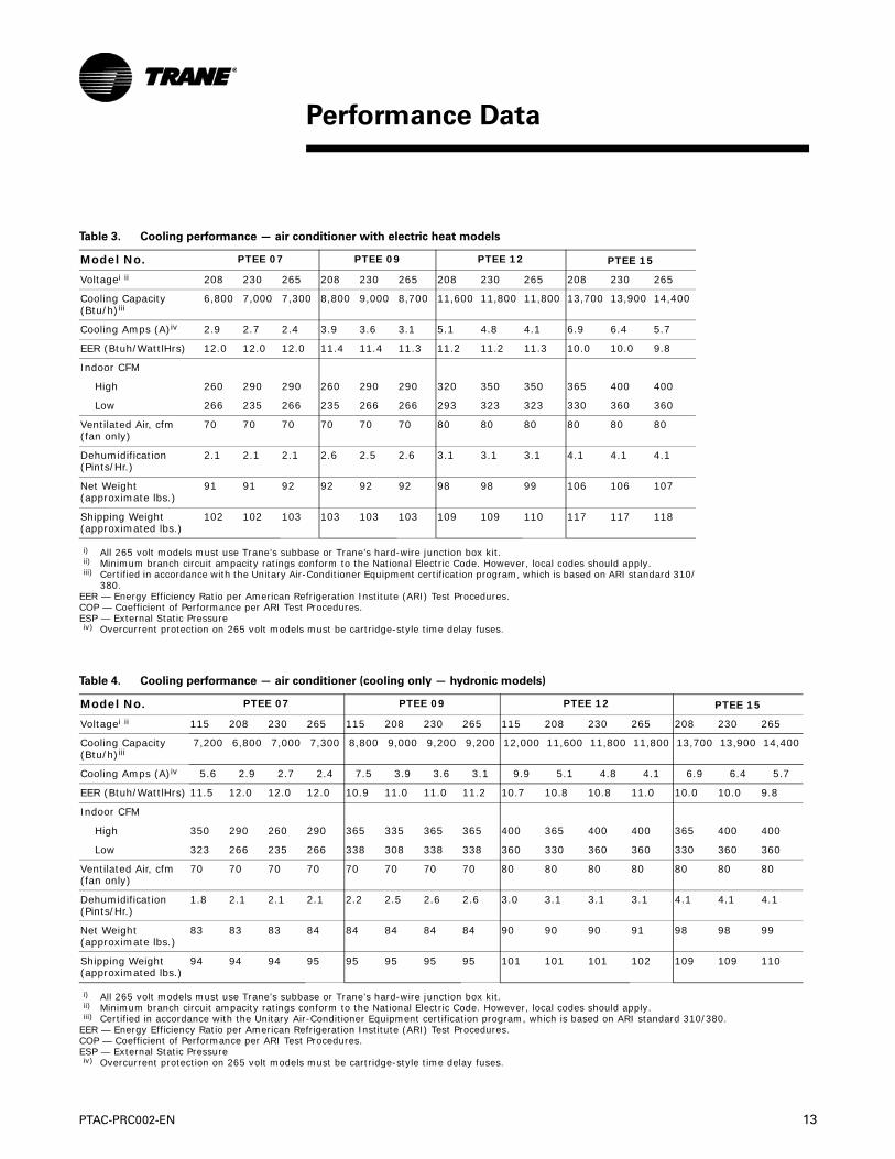
Table 3. Cooling performance — air conditioner with electric heat models
Model No. PTEE 07 PTEE 09 PTEE 12 PTEE 15
Voltagei ii
i) All 265 volt models must use Trane’s subbase or Trane’s hard-wire junction box kit.ii) Minimum branch circuit ampacity ratings conform to the National Electric Code. However, local codes should apply.
208 230 265 208 230 265 208 230 265 208 230 265
Cooling Capacity (Btu/h)iii
iii) Certified in accordance with the Unitary Air-Conditioner Equipment certification program, which is based on ARI standard 310/380.
EER — Energy Efficiency Ratio per American Refrigeration Institute (ARI) Test Procedures.COP — Coefficient of Performance per ARI Test Procedures.ESP — External Static Pressure
6,800 7,000 7,300 8,800 9,000 8,700 11,600 11,800 11,800 13,700 13,900 14,400
Cooling Amps (A)iv
iv) Overcurrent protection on 265 volt models must be cartridge-style time delay fuses.
2.9 2.7 2.4 3.9 3.6 3.1 5.1 4.8 4.1 6.9 6.4 5.7
EER (Btuh/WattlHrs) 12.0 12.0 12.0 11.4 11.4 11.3 11.2 11.2 11.3 10.0 10.0 9.8
Indoor CFM
High 260 290 290 260 290 290 320 350 350 365 400 400
Low 266 235 266 235 266 266 293 323 323 330 360 360
Ventilated Air, cfm (fan only)
70 70 70 70 70 70 80 80 80 80 80 80
Dehumidification (Pints/Hr.)
2.1 2.1 2.1 2.6 2.5 2.6 3.1 3.1 3.1 4.1 4.1 4.1
Net Weight (approximate lbs.)
91 91 92 92 92 92 98 98 99 106 106 107
Shipping Weight (approximated lbs.)
102 102 103 103 103 103 109 109 110 117 117 118
Table 4. Cooling performance — air conditioner (cooling only — hydronic models)
Model No. PTEE 07 PTEE 09 PTEE 12 PTEE 15
Voltagei ii
i) All 265 volt models must use Trane’s subbase or Trane’s hard-wire junction box kit.ii) Minimum branch circuit ampacity ratings conform to the National Electric Code. However, local codes should apply.
115 208 230 265 115 208 230 265 115 208 230 265 208 230 265
Cooling Capacity (Btu/h)iii
iii) Certified in accordance with the Unitary Air-Conditioner Equipment certification program, which is based on ARI standard 310/380.EER — Energy Efficiency Ratio per American Refrigeration Institute (ARI) Test Procedures.COP — Coefficient of Performance per ARI Test Procedures.ESP — External Static Pressure
7,200 6,800 7,000 7,300 8,800 9,000 9,200 9,200 12,000 11,600 11,800 11,800 13,700 13,900 14,400
Cooling Amps (A)iv
iv) Overcurrent protection on 265 volt models must be cartridge-style time delay fuses.
5.6 2.9 2.7 2.4 7.5 3.9 3.6 3.1 9.9 5.1 4.8 4.1 6.9 6.4 5.7
EER (Btuh/WattlHrs) 11.5 12.0 12.0 12.0 10.9 11.0 11.0 11.2 10.7 10.8 10.8 11.0 10.0 10.0 9.8
Indoor CFM
High 350 290 260 290 365 335 365 365 400 365 400 400 365 400 400
Low 323 266 235 266 338 308 338 338 360 330 360 360 330 360 360
Ventilated Air, cfm (fan only)
70 70 70 70 70 70 70 70 80 80 80 80 80 80 80
Dehumidification (Pints/Hr.)
1.8 2.1 2.1 2.1 2.2 2.5 2.6 2.6 3.0 3.1 3.1 3.1 4.1 4.1 4.1
Net Weight (approximate lbs.)
83 83 83 84 84 84 84 84 90 90 90 91 98 98 99
Shipping Weight (approximated lbs.)
94 94 94 95 95 95 95 95 101 101 101 102 109 109 110
Performance Data
14 PTAC-PRC002-EN
Performance Data
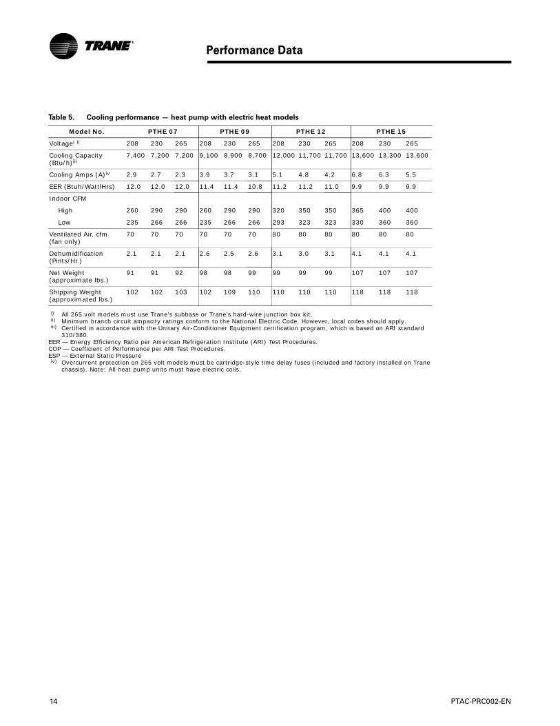
Table 5. Cooling performance — heat pump with electric heat models
Model No. PTHE 07 PTHE 09 PTHE 12 PTHE 15
Voltagei ii
i) All 265 volt models must use Trane’s subbase or Trane’s hard-wire junction box kit.ii) Minimum branch circuit ampacity ratings conform to the National Electric Code. However, local codes should apply.
208 230 265 208 230 265 208 230 265 208 230 265
Cooling Capacity (Btu/h)iii
iii) Certified in accordance with the Unitary Air-Conditioner Equipment certification program, which is based on ARI standard 310/380.
EER — Energy Efficiency Ratio per American Refrigeration Institute (ARI) Test Procedures.COP — Coefficient of Performance per ARI Test Procedures.ESP — External Static Pressure
7,400 7,200 7,200 9,100 8,900 8,700 12,000 11,700 11,700 13,600 13,300 13,600
Cooling Amps (A)iv
iv) Overcurrent protection on 265 volt models must be cartridge-style time delay fuses (included and factory installed on Trane chassis). Note: All heat pump units must have electric coils.
2.9 2.7 2.3 3.9 3.7 3.1 5.1 4.8 4.2 6.8 6.3 5.5
EER (Btuh/WattlHrs) 12.0 12.0 12.0 11.4 11.4 10.8 11.2 11.2 11.0 9.9 9.9 9.9
Indoor CFM
High 260 290 290 260 290 290 320 350 350 365 400 400
Low 235 266 266 235 266 266 293 323 323 330 360 360
Ventilated Air, cfm (fan only)
70 70 70 70 70 70 80 80 80 80 80 80
Dehumidification (Pints/Hr.)
2.1 2.1 2.1 2.6 2.5 2.6 3.1 3.0 3.1 4.1 4.1 4.1
Net Weight (approximate lbs.)
91 91 92 98 98 99 99 99 99 107 107 107
Shipping Weight (approximated lbs.)
102 102 103 102 109 110 110 110 110 118 118 118

PTAC-PRC002-EN 15
Performance Data
Table 6. Heating performance — heat pump with electric heat models
Model No. PTHE07 PTHE09 PTHE12 PTHE15
Voltagei
i) All 265 volt models must use Trane’s subbase or Trane’s hard-wire junction box kit.
208 230 265 208 230 265 208 230 265 208 230 265
Heating capacity(Btu/H)ii
ii) Heating capacity and efficiency are based on unit operation without condensate pump.
5,900 6,100 6,100 7,600 7,800 7,300 9,900 10,100 10,100 12,200 12,500 12,500
Heating amps
2.0KW 7.9 8.9 7.7 7.9 8.9 7.7 7.9 8.9 7.7 7.9 8.9 7.7
3.0KW 11.8 13.4 11.6 11.8 13.4 11.6 11.8 13.4 11.6 11.8 13.4 11.6
5.0KW * * * 19.7 22.2 19.3 19.7 22.2 19.3 19.7 22.2 19.3
COP (W/W) 3.2 3.2 3.2 3.2 3.2 3.0 3.1 3.1 3.2 2.9 2.9 2.9
Indoor CFM (
High 290 260 290 290 260 290 350 320 350 400 365 400
Low 266 235 266 266 235 266 323 293 323 360 330 360
Table 7. Temperature across indoor coils —air conditioner
Room Air Room Air PTEE0701 PTEE0702 PTEE0901 PTEE0902 PTEE1201 PTEE1202 PTEE1501 PTEE1502
Dry Wet Temperature Across Temperature Across Temperature Across Temperature Across
Bulb Bulb Indoor Coil (∆T) Indoor Coil (∆T) Indoor Coil (∆T) Indoor Coil (∆T)
°F °F Min Max Min Max Min Max Min Max
85 1 3 2 6 1 5 1 4
80 8 13 11 14 9 13 8 12
90 75 19 22 19 22 18 22 16 20
70 30 33 28 30 26 30 25 27
80 4 9 7 11 5 10 5 8
75 14 19 15 18 13 18 12 16
85 70 23 27 23 25 21 25 20 23
65 34 36 31 33 29 33 28 30
75 9 14 11 14 9 13 8 12
70 18 21 18 20 15 20 15 18
80 65 26 29 24 27 23 26 21 24
60 35 36 32 33 29 33 29 30
70 12 16 13 16 10 15 10 14
65 18 22 18 21 15 20 15 19
75 60 25 28 23 26 21 25 20 24
55 31 34 28 31 26 30 26 28
65 12 15 12 14 9 13 9 13
70 60 17 20 16 18 13 17 13 17
55 22 24 20 22 18 21 17 21
16 PTAC-PRC002-EN
Performance Data
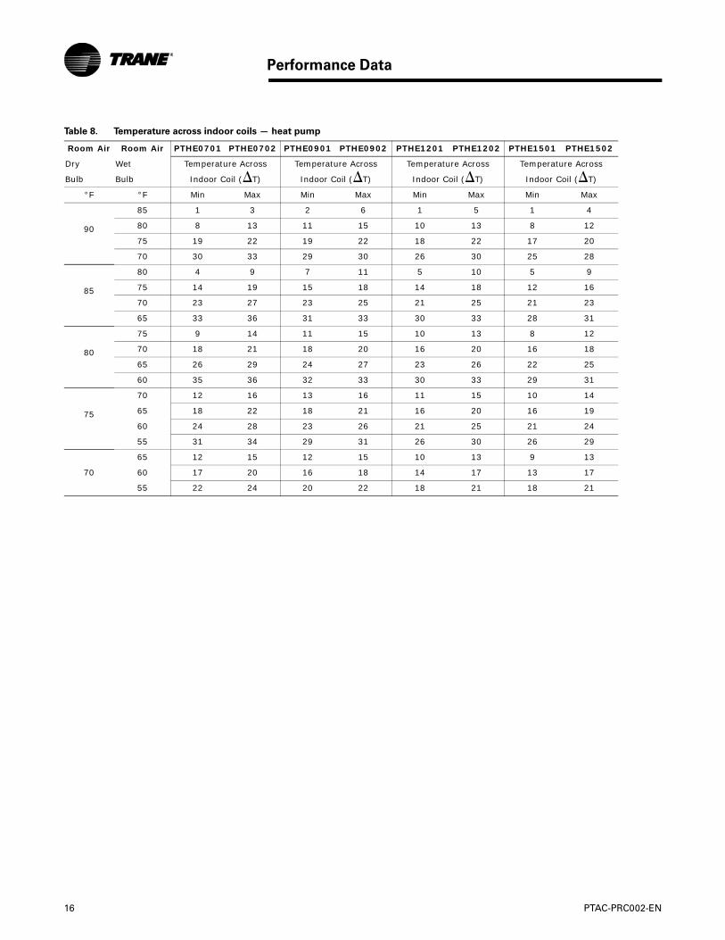
Table 8. Temperature across indoor coils — heat pump
Room Air Room Air PTHE0701 PTHE0702 PTHE0901 PTHE0902 PTHE1201 PTHE1202 PTHE1501 PTHE1502
Dry Wet Temperature Across Temperature Across Temperature Across Temperature Across
Bulb Bulb Indoor Coil (∆T) Indoor Coil (∆T) Indoor Coil (∆T) Indoor Coil (∆T)
°F °F Min Max Min Max Min Max Min Max
90
85 1 3 2 6 1 5 1 4
80 8 13 11 15 10 13 8 12
75 19 22 19 22 18 22 17 20
70 30 33 29 30 26 30 25 28
85
80 4 9 7 11 5 10 5 9
75 14 19 15 18 14 18 12 16
70 23 27 23 25 21 25 21 23
65 33 36 31 33 30 33 28 31
80
75 9 14 11 15 10 13 8 12
70 18 21 18 20 16 20 16 18
65 26 29 24 27 23 26 22 25
60 35 36 32 33 30 33 29 31
75
70 12 16 13 16 11 15 10 14
65 18 22 18 21 16 20 16 19
60 24 28 23 26 21 25 21 24
55 31 34 29 31 26 30 26 29
65 12 15 12 15 10 13 9 13
70 60 17 20 16 18 14 17 13 17
55 22 24 20 22 18 21 18 21

PTAC-PRC002-EN 17
Performance Data
Table 9. Heating capacity — water
Pressure Drop (psig) 7000 & 9000 Btu Units 12000 Btu Units 15000 Btu Units
200°F EWT 180°F EWT 200°F EWT 180°F EWT 200°F EWT 180°F EWT
Fan Speed Fan Speed Fan Speed Fan Speed Fan Speed Fan Speed
gpm Coil 2-WayValve
Hi Lo Hi Lo Hi Lo Hi Lo Hi Lo Hi Lo
1.00 0.93 0.16 14.9 13.4 12.6 11.2 16.9 14.4 14.3 12.2 17.9 15.5 15.0 13.3
1.13 1.03 0.20 15.2 13.7 12.9 11.5 17.4 14.7 14.6 12.4 18.3 16.0 15.4 13.7
1.25 1.14 0.25 15.5 14.0 13.1 11.7 17.7 15.0 14.9 12.6 18.7 16.3 15.7 14.0
1.38 1.26 0.30 15.8 14.3 13.4 11.9 18.1 15.2 15.2 12.9 19.0 16.7 16.0 14.3
1.50 1.40 0.36 16.0 14.5 13.6 12.1 18.4 15.5 15.5 13.1 19.4 17.0 16.3 14.6
1.63 1.55 0.43 16.2i 14.7 13.8 12.3 18.7 15.7 15.7 13.2 19.7 17.3 16.6 14.8
1.75 1.71 0.49 16.4 14.9 13.9 12.5 19.0 15.8 16.0 13.4 19.9 17.5 16.8 15.0
1.88 1.89 0.57 16.6 15.1 14.1 12.6 19.2 16.0 16.2 13.5 20.2 17.7 17.0 15.2
2.00 2.10 0.64 16.8 15.2 14.2 12.7 *19.3 16.1 16.2 13.6 20.4 17.8 17.2 15.3
2.13 2.32 0.73 16.9 15.3 14.3 12.8 19.6 16.3 16.5 13.7 *20.4 18.0 17.2 15.4
2.25 2.57 0.81 17.0 15.4 14.4 12.9 19.7 16.3 16.6 13.8 20.7 18.0 17.5 15.5
2.38 2.84 0.91 17.1 15.4 14.5 12.9 19.8 16.4 16.7 13.9 20.9 18.1 17.6 15.5
2.50 3.14 1.00 17.2 15.5 14.5 12.9 19.9 16.5 16.8 13.9 21.0 18.1 17.7 15.5
2.63 3.48 1.11 17.2 15.5 14.6 12.9 20.0 16.5 16.8 13.9 21.0 18.1 17.7 15.5
2.75 3.85 1.21 17.2 15.5 14.6 13.0 20.0 16.6 16.8 14.0 21.1 18.1 17.7 15.5
i) Based on ARI Rating Conditions of 70°F Entering Air Temp., 200°F Entering Water Temp and 180°F Leaving Water Temp.
Max. Water Temperature 200°F Max. Water Pressure - 200 psig.
Table 10. Heating capacity — steam
7,000 & 9,000 Btu Units
12,000 Btu Units 15,000 Btu Units
Steam Fan Speed Fan Speed Fan Speed
psig High Low High Low High Low
2i 20,200 17,800 21,700 18,300 23,700 21,000
3 20,700 18,300 22,100 19,000 25,700 21,900
4 20,800 18,500 22,800 19,300 26,300 23,77
i) Based on ARI rating conditions of 70°F entering air temperature and 2 psig steam pressure.
Note: Maximum steam pressure 5 psig.

18 PTAC-PRC002-EN
Performance Data
Table 11. Hydronic water valve pressure drop
2-WayValve
3-WayValve
Bypass
3-WayValve
Service
3-WayValve
Bypass and Service
Pressure Drop
Pressure Drop
Pressure Drop
Pressure Drop
Water GPM
(psig) (psig) (psig) (psig)
1.00 0.16 0.11 0.04 0.06
1.13 0.20 0.14 0.05 0.08
1.25 0.25 0.17 0.06 0.10
1.38 0.30 0.21 0.08 0.12
1.50 0.36 0.25 0.09 0.14
1.63 0.43 0.30 0.11 0.17
1.75 0.49 0.34 0.12 0.19
1.88 0.57 0.39 0.14 0.22
2.00 0.64 0.44 0.16 0.25
2.13 0.73 0.50 0.18 0.28
2.25 0.81 0.56 0.20 0.32
2.38 0.91 0.63 0.23 0.35
2.50 1.00 0.69 0.25 0.39
2.63 1.11 0.77 0.28 0.43
2.75 1.21 0.84 0.30 0.47
CV=2.5 CV=3.0 CV=5.0 CV=4.0

PTAC-PRC002-EN 19
Table 11. Electric heat capacity and electrical data, models PTEE and PTHEi
i) All heat pumps have electric heat.
Voltageii
ii) Minimum voltage on 230/208 volt models is 187 volts; maximum is 253 volts. Minimum voltage on 265 volt models is 239 volts; maximum is 292 volts.
Size (kW) Btu/h Heating watts
Heating amps
Minimum circuit ampacityiii
iii) Minimum branch circuit ampacity ratings conform to the National Electric Code. However, local codes should apply.
Circuit protectioniv
iv) Overcurrent protection for all units without electric heaters is 15 amps. Overcurrent protection on 265 volt mod-els must be cartridge-style time delay fuses.
Plug
230/208 2.0/1.6 6,800/5,600
2000/1600
8.9/7.9 11.4 15 6 - 15 P
230/208 3.0/2.5 10,200/8,400
3000/2500
13.4/11.8 17 20 6 - 20 P
230/208 5.0/4.1 17,100/14,000
5000/4100
22.2/19.7 28 30 6 - 30 P
265 2.0 6,800 2000 7.7 9.9 15 7 - 15 P
265 3.0 10,200 3000 11.6 14.7 20 7 - 20 P
265 5.0 17,100 5000 19.3 24.4 30 7 - 30 P
Table 12. Power receptacle configurations
Unit Voltage Rating
230/208
230/208
230/208 265 265
Unit plug
Plug amp rating
15 20 30 15/20 30
NEMA designation
6-15P 6-20P 6-30P 7-15P/7-20P 7-30P
Receptacle
Receptacle amp rating
20 20 30 15/20 30
NEMA designation
6-20R 6-20R 6-30R 7-15R/7-20R 7-30R
Electric Power

20 PTAC-PRC002-EN
Electric Power
Table 13. Unit power supply
Voltage Accessory Accessory part number
115V
Option 1. Power Cord BAYPCRD007
115V 15A Receptacle Field Supplied
Option 2. Power Cord BAYPCRD007
Subbase BAYSUB001
115V 15A Receptacle Field Supplied
Option 3. Hard Wire Kit BAYHWRK001
Connector for Hardwire BAYCNHK031
265 V
Option 1. Subbase BAYSUB001
Receptacle BAYSCKT003, BAYSCKT004
Power Cord BAYPCRD004, BAYPCRD005, BAYPCRD006
Fuses BAYFUSE001, BAYFUSE002, BAYFUSE003
Power Switch (optional) BAYPSW002
Option 2. Hard Wire Kit BAYHWRK001
Connector for Hardwire BAYCNHK021, BAYCNHK022 , BAYCNHK023
Power Switch (optional) BAYPSW002
230/ 208 V
Option 1. Power Cord BAYPCRD001 or BAYPCRD008, BAYPCRD002 or BAYPCRD009, BAYPCRD003
Power Switch (optional) BAYPSW002
Option 2. Subbase BAYSUB001
Receptacle BAYSCKT001, BAYSCKT002
Power Cord BAYPCRD001 or BAYPCRD008, BAYPCRD002 or BAYPCRD009, BAYPCRD003
Circuit Breaker (Optional)
BAYCBKR001, BAYCBKR002, BAYCBKR003
Power Switch (optional) BAYPSW002
Option 3. Hard Wire Kit BAYHWRK001
Connector for Hardwire BAYCNHK014, BAYCNHK015, BAYCNHK016
Power Switch (optional) BAYPSW002

PTAC-PRC002-EN 21
Figure 2. Unit with wall sleeve and subbase accessory
Dimensions

22 PTAC-PRC002-EN
Dimensions
Figure 3. Wall sleeve dimensions
Figure 4. Minimum unit clearances
Table 14. Minimum clearances and projections
Option In. Mm In. Mm In. Mm
Minimum clearances Minimum projection
A B C
Wall sleeve only 3 75 0 0 0 0
Subbase kit 3 75 3 1/4 85 2 3/4 70
Leveling legs kit 3 75 3 75 2 50
Hydronic heat kiti
i) Max height is based on skirt options available.
9 230 2-6”ii
ii) This dimension can be from 2-6", but if this dimension exceeds 6" an extended standard kick plate is necessary.
50 -150iii
iii) This dimension can be from 50-150mm, but if this dimension exceeds 150mm an extended standard kick plate is necessary.
3-3 1/8iv
iv) To achieve a flush fit between the hydronic front and the finished wall, dimension "C" must be between 3" and 3-1/8". If this dimension is more than 3-1/8" there will be a gap between the front and the wall. This gap could permit occupant access to hydronic lines or other dangerous parts.
76-80v
v) To achieve a flush fit between the hydronic front and the finished wall, dimension "C" must be between 76-80mm. If this dimension is more than 80mm there will be a gap between the front and the wall. This gap could permit occupant access to hydronic lines or other dangerous parts.
Drain kit 3 75 0vi
vi) If inside mounted then B = 1-1/2 inches
1vii
vii) If inside mounted then B = 40 mm
0 0
Hardwire kit 3 75 3 75 0 0
Figure 5. Minimum unit clearances

PTAC-PRC002-EN 23
Dimensions
Figure 6. Top view of hydronic kit
Figure 7. Side view of hydronic unit
PTAC Wall Sleeve
Air dischargeUnit controls compartment
5”1-
1-3/8”- 1-1/2”
12-1/4”
Outer Wall
Inside Room
Slope wall sleeve towards outside of building
Front Panel
Wall Sleeve

24 PTAC-PRC002-EN
Mechanical Specifications
General
Packaged Terminal Air Conditioners shall be of the sizes and capacities shown on the schedule and in the specifications. The units shall be located as shown on the drawings and each shall consist of a chassis, wall sleeve, outdoor grille, and subbase if specified.
Units shall ship with a plastic front cover with the exception of hydronic models. Hydronic models require the installation of a hot water or steam kit that will include a metallic front cover made of galvanized steel.
Units shall ship with a polycarbonate double sloped drain pan.
Units shall be approved and listed by cULus. Unit capacity and efficiency performance shall be certified in accordance with ARI standard 310/380-1993. Unit dimensions shall not exceed 42” wide and 16-1/6” high with room cabinet in place.
Units shall exceed ASHRAE Standard 90.1 for energy efficiency.
Unit shall be tested for conformance to ASTM water infiltration specification ASTM 331-00, which assures no water infiltration when tested at eight inches of rain per hour at 63 mph wind for 15 minutes.
Units shall be designed to operate on 115, 208/230, or 265 volts, 60 Hz., single phase power.
Heating/Cooling Chassis
The chassis shall consist of the following sections and components:
Chassis shall be slide-in, plug-in type; ready to operate after installation.
Hermetically-sealed refrigerant system with external vibration isolated rotary-type compressor, condenser and evaporator coils and capillary refrigerant control.
The airflow system shall consist of one permanent split-capacitor, direct-drive, two-speed fan motor for the outdoor fan, and a separate permanent split-capacitor, two-speed fan motor for the indoor fan. Outdoor fan shall be multi-blade axial-flow design made with five injection molded plastic fan blades with slinger ring. Indoor fan shall be a cylindrical cross-flow blower fan to assure an evenly distributed air flow. All motors on the exterior side of the weather barrier shall be of an enclosed design to reduce the effects of moisture and corrosion.
Units, except hydronic models, shall have a resistance heater to provide specified heat output.
Condenser and evaporator coils to be constructed of high-efficiency, aluminum-enhanced louvered fins and grooved copper tubing necessary to achieve EER and COP rating of the unit.
Adjustable-closing fresh air vent, with vent door secured for shipping, and optional securing in the closed position, with a concealed manual control. The vent control shall allow 70 CFM (7,000 and 9,000 Btu units) or 80 CFM (12,000 and 15,000 Btu units) of fresh air to be drawn into the room when the unit’s blower is operating.
Heat Pump Chassis
Heat pump units shall automatically change from heat pump operation to electric resistance heat when heat pump operation is unable to produce sufficient heat to maintain room temperature within 2.5° F of thermostat setpoint, or when the outdoor air switch-over temperature falls below 20° F.
Heat pump unit shall automatically begin an active defrost cycle when the outdoor coil temperature drops below 21°F. Defrosting shall be accomplished by active defrost with unit automatically reinitiating heat pump operation when outdoor coil reaches 54°F or six minutes has elapsed after defrost has been initiated.
Mechanical Specifications

PTAC-PRC002-EN 25
Mechanical Specifications
Front Panel
Units shall have a matching, easily removable, textured finish, wrap-around room cabinet molded of High Impact Polystyrene (HIPS) to resist corrosion and damage. Front panel shall have a sloped discharge so that obstructions are not placed on the unit. Cabinet shall have a low profile depth of 7 1/4” to minimize the unit’s impact on room space. The front panel shall have the following features:
Adjustable indoor discharge air louvers that provide a 15 degree off vertical air pattern with an alternate position to provide a 40 degree off vertical air pattern. Louvers will be a polycarbonate material to resist bending, cracking, rusting and corrosion.
Air discharge area accessible for cleaning without tools when room front is removed.
Filtration
Unit shall have indoor and outdoor air filters. Filters shall be washable polypropylene mesh. Indoor filters shall be accessible without requiring removal of room cabinet from chassis.
Controls
Unit controls shall be easily accessible for selection of unit operation mode and temperature setpoint. The controller display shall clearly indicate the room temperature,setpoint, and operating mode.
Controls shall utilize solid state microprocessor based controller to allow the following operations:
Freeze protection that automatically activates the electric resistance heater and fan motor to warm and
circulate indoor air to help prevent damage due to freezing temperatures. Freeze protection shall operate as long as unit is connected to powered electrical circuit.
Remote Thermostat compatibility with 4 or 5 wire remote thermostats.
Electronic temperature limiting to limit maximum and minimum temperatures. Minimum cooling range shall be capable of being set between 50° F and 65° F, and heating range between 75° F and 90°F.
A fan cycle switch to permit the following three independently selectable modes for heating and cooling fan operation; 1)cycle with compressor 2)ON continuously, OFF in OFF mode 3)ON continuously, HIGH in OFF mode
Compatibility with 2 wire Front Desk Control systems.
The unit shall be capable of on board diagnostics. This diagnostic LCD is capable of displaying 8 diagnostics : Compressor Failure Indoor Temperature – No Backup Available, Indoor Temperature – Unit Sensor Failure 1, Indoor Temperature – Display Sensor Failure1, Indoor Coil Temperature Failure, Outdoor Temperature Failure, Outdoor Coil Temperature Failure, and Configuration Corrupted.

26 PTAC-PRC002-EN
Warranty
Standard Warranty
Warranty and Liability
Trane will repair or replace, free of charge, any part which proves to be defective due to workmanship or materials under the full first-year warranty. Trane will repair or replace, free of charge, the evaporator, condenser, compressor, or connecting tubing which proves to be defective due to workmanship or materials under the full five-year sealed system warranty. During the 2nd through 5th year functional parts warranty, Trane will provide free of charge, functional parts, which prove to be defective due to workmanship or materials. Components covered are switches, solenoids, fan motors, thermostats, circuit boards, factory installed heaters, blower wheel, fan propeller, capacitor. This LIMITED WARRANTY does not include diagnostic time, labor, or any transportation and reinstallation charges that may be required.
Warranty Limitations
Warranties are effective as of the original date of purchase. An authorized Trane warranty agent must perform all warranty service. Reimbursement for warranty service is limited to normal service charges performed during the servicer’s normal business hours. This applies only to original installation within the continental United States, Hawaii, Alaska, and Canada. Warranties are void if the product serial identification tag is removed or defaced to a point where the unit cannot be identified. In no event shall Trane be responsible for incidental or consequential damages.
Owner’s Responsibilities
The owner is responsible for providing proofs of purchase (sales invoice), providing normal care and maintenance, and making the product reasonably accessible for service. Other responsibilities include paying for service calls related to product installation or usage instructions and paying for replacement of filters, fuses and circuit breakers. Under the Limited Warranty, the owner is responsible for servicer’s travel charges, labor, parts freight and cartage, if required.
Warranty Exclusions
The Trane Company is not responsible for damage as a result of flooding, lightning, fire, wind, and accidents beyond Trane’s control, damage as a result of products not installed according to Trane’s instructions and specifications, and damage or failure resulting from installation in an environment containing highly corrosive chemical agents. Other exclusions consist of damage and/or no start conditions caused by improper or inadequate electrical connections, damage resulting from failure to perform routine maintenance as specified in the Service Manual, and replacement of fuses and replacement or resetting of circuit breakers.
Warranty

Trane
A business of American Standard Companies
www.trane.com
For more information, contact your local Trane office or e-mail us at [email protected]
Literature Order Number PTAC-PRC002-EN
Date March 2007
Supersedes PTAC-PRC002-EN 10/06
Trane has a policy of continuous product and product data improvement and reserves the right to change design and specifications without notice.


