Paavai Institutions Department of IT
195
Paavai Institutions Department of IT UNIT-1 1. 1 UNIT 1 INTRODUCTION www.Vidyarthiplus.com www.Vidyarthiplus.com
Transcript of Paavai Institutions Department of IT
Paavai Institutions Department of IT
UNIT-1 1. 1
UNIT 1
INTRODUCTION
www.Vidyarthiplus.com
www.Vidyarthiplus.com
Paavai Institutions Department of IT
UNIT-1 1. 2
CONTENTS
1.1Mobile Communication
1.1.1 Guided Transmission
1.1.2 Unguided Wireless Transmission
1.1.3 Antennae
1.1.4 Modulation of wireless signals:
1.1.5 Multiplexing
1.1.6 Introduction to 2G and 3G Data Communication Standards
1.1.7 Introduction to WPANs and WLANs
1.2 Mobile computing
1.2.1 Ubiquitous computing
1.2.2 Pervasive Computing
1.2.3 Limitations to mobile computing
1.3 Mobile Computing Architecture
1.3.1 Functions of Operating System
1.3.2 Middleware for Mobile Systems
1.3.3 Mobile Computing Architectural Layer
1.3.4 Protocols
1.3.5 Mobile Computing system Layers
1.4 Mobile Devices
1.5 Mobile System Networks
1.6 Data Dissemination
1.6.1 Data Synchronization Example
1.7 Mo bility Management
1.8 Security
1.8.1 Cryptography
1.9 Introduction to Cellular systems
1.9.1 Cellular systems: technologies & subscribers
www.Vidyarthiplus.com
www.Vidyarthiplus.com

Paavai Institutions Department of IT
UNIT-1 1. 3
1.10 GSM: Global System for Mobile Communication
1.10.1 GSM Architecture
1.10.2 GSM Services
1.10.3 GSM: Radio Technology
1.11 GPRS: General Packet Radio Service
1.11.1 GPRS – Architecture
1.11.2 GPRS: Channel Coding and Multiplexing
1.11.3 GPRS architecture and interfaces
1.11.4 GPRS Core Network Functions
1.11.5 GPRS: Protocol Stack
1.11.6 GPRS: Obtaining IP Connectivity
1.12 Question Bank
www.Vidyarthiplus.com
www.Vidyarthiplus.com
Paavai Institutions Department of IT
UNIT-1 1. 4
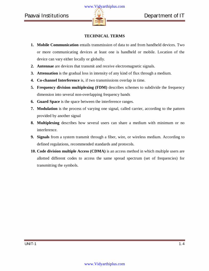
TECHNICAL TERMS
1. Mobile Communication entails transmission of data to and from handheld devices. Two
or more communicating devices at least one is handheld or mobile. Location of the
device can vary either locally or globally.
2. Antennae are devices that transmit and receive electromagnetic signals.
3. Attenuation is the gradual loss in intensity of any kind of flux through a medium.
4. Co-channel Interference is, if two transmissions overlap in time.
5. Frequency division multiplexing (FDM) describes schemes to subdivide the frequency
dimension into several non-overlapping frequency bands
6. Guard Space is the space between the interference ranges.
7. Modulation is the process of varying one signal, called carrier, according to the pattern
provided by another signal
8. Multiplexing describes how several users can share a medium with minimum or no
interference.
9. Signals from a system transmit through a fiber, wire, or wireless medium. According to
defined regulations, recommended standards and protocols.
10. Code division multiple Access (CDMA) is an access method in which multiple users are
allotted different codes to access the same spread spectrum (set of frequencies) for
transmitting the symbols.
www.Vidyarthiplus.com
www.Vidyarthiplus.com
Paavai Institutions Department of IT
UNIT-1 1. 5
1. INTRODUCTION
1.1 Mobile Communication Communication is a two-way transmission and reception of data streams. Signals for
Voice, data, or multimedia streams are transmitted. Signals are received by a receiver.
Signals from a system transmit through a fiber, wire, or wireless medium, according to
defined regulations, recommended standards and protocols.
Mobile Communication entails transmission of data to and from handheld devices. Two
or more communicating devices at least one is handheld or mobile. Location of the device can
vary either locally or globally. Communication takes place through a wireless, distributed, or
diversified network.
1.1.1 Guided Transmission
Metal wires and optical fibers are guided or wired transmission of data. Guided
transmission of electrical signals takes place using four types of cables are
1. Optical fiber for pulses of wavelength 1.35–1.5 µm
2. Coaxial cable for electrical signals of frequencies up to 500 MHz and up to a range of
about 40 m.
3. Twisted wire pairs ─ for conventional (without coding) electrical signals of up to 100
KHz and up to a range of 2 km, or for coded signals of frequencies up to 200 MHz and
a range of about 100 m.
4. Power lines, a relatively recent advent in communication technology─ used for long
range transmission of frequencies between 10 kHz and 525 kHz.
Guided Transmission Advantages
Here the transmission is along a directed path from one point to another. There is
practically no interference in transmission from any external source or path. Using multiplexing
and coding, a large number of signal-sources simultaneously transmitted along an optical fiber, a
coaxial cable, or a twisted-pair cable.
www.Vidyarthiplus.com
www.Vidyarthiplus.com
Paavai Institutions Department of IT
UNIT-1 1. 6
Guided Transmission Disadvantages
Signal transmitter and receiver are fixed (immobile). Hence there is no mobility of
transmission and reception points. The number of transmitter and receiver systems limits the
total number of interconnections possible.
1.1.2 Unguided─ Wireless Transmission
Electrical signals transmitted by converting them into electromagnetic radiation.
Radiation transmitted via antennae that radiate electromagnetic signals. The electromagnetic
radiation are related by the classical formula
f = c/λ = (300/ λ) MHz [λ in meter].
The frequencies and wavelengths of transmitters for various ranges are as follows:
Long-wavelength radio, very low frequency (LW): 30 kHz to 1 MHz (10,000 to 300m)
Medium-wavelength radio, medium frequency (MW): 0.5 to 2 MHz (600 to 150m)
Short-wavelength radio, high frequency (SW): 6 to 30 MHz (50 to 10m)
FM Radio band frequency (FM): 87.5 to 108 MHz (3.4 to 2.8m)
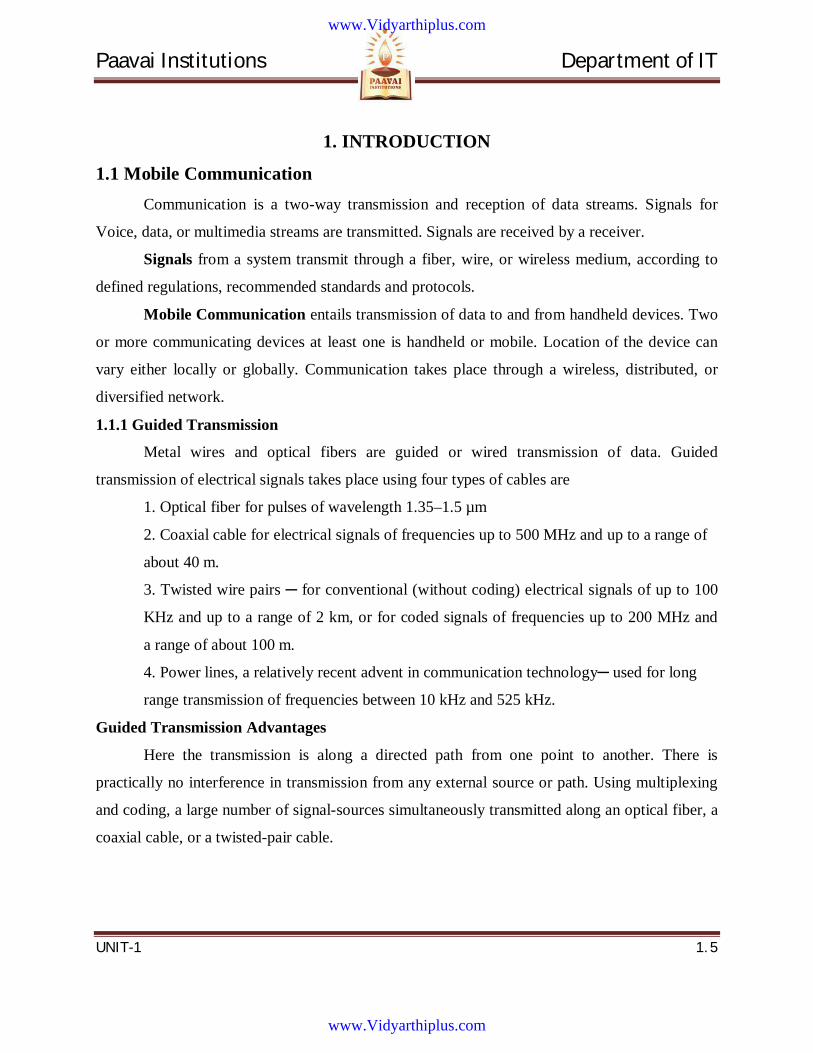
Very high frequency (VHF): 50 to 250 MHz (6 to 1.2m)
Ultra high frequency (UHF): 200 to ~2000MHz (1.5 to 0.15m)
Super high microwave frequency (SHF): 2 to 40 GHz (~15 to 0.75cm)
Extreme High frequency (EHF): Above 40 GHz to 1014 Hz (0.75cm to 3 µm)
Far Infrared: Optical wavelengths between 1.0 µm to 2.0 µm and [(1.5 to 3) X 1014 Hz
(0.15-0.3 THz)]
Infrared: 0.90 µm to 0.85 µm in wavelength and ~(3.3 to 3.5) X 1014Hz [350 to 330
THz].
Visible Light: 0.70 µm to 0.40 µm in wavelength and ~ (4.3 to 7.5) X 1014 Hz (~430 to
750 THZ).
Ultraviolet: <0.40 µm in wavelength (>750 THz).
1.1.2.1 Advantages and Disadvantages of VHF and UHF
The Advantages and Disadvantages of VHF and UHF are listed below.
www.Vidyarthiplus.com
www.Vidyarthiplus.com
Paavai Institutions Department of IT
UNIT-1 1. 7
1.1.3 Antennae
Antennae are devices that transmit and receive electromagnetic signals. Most function
efficiently for relatively narrow frequency ranges. If not properly tuned to the frequency band in
which the transmitting system connected to it operates, the transmitted or received signals may
be impaired. The forms of antennae are chiefly determined by the frequency ranges they operate
in and can vary from a single piece of wire to a parabolic dish.
www.Vidyarthiplus.com
www.Vidyarthiplus.com
Paavai Institutions Department of IT
UNIT-1 1. 8
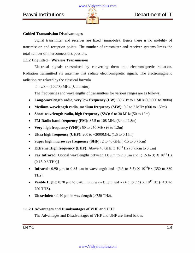
1.1.3.1 Radiation Pattern of Antenna:
The important feature of an antenna is
Signal amplitude at an instant is identical along the pattern.
Circular pattern means that radiated energy, and thus signal strength, is equally
distributed in all directions in the plane.
A pattern in which the signal strength is directed along a specific direction in the
plane.
/2 Dipole Antenna /4 Dipole Antenna
/4 Radiation pattern in y-z and x-z planes Directed Transmission Antenna Radiation
pattern in z-y and z-z planes
Same Antenna Radiation pattern in x-y Planes
Figure 1.1 Antenna Radiation Pattern in Planes
www.Vidyarthiplus.com
www.Vidyarthiplus.com
Paavai Institutions Department of IT
UNIT-1 1. 9
1.1.3.2 Propagation of signals
The Wireless propagation of signals faces many complications. Mobile
communication renders reliable wireless transmission much more difficult than
communication between fixed antennae. The antenna height and size at mobile terminals
are generally quite small. The obstacles in the vicinity of the antenna have a significant
influence on the propagated signal. The propagation properties vary with place and, for a
mobile terminal, with time. Attenuation is the gradual loss in intensity of any kind of
flux through a medium. For instance, sunlight is attenuated by dark glasses, X-rays are
attenuated by lead, and light and sound are attenuated by water.
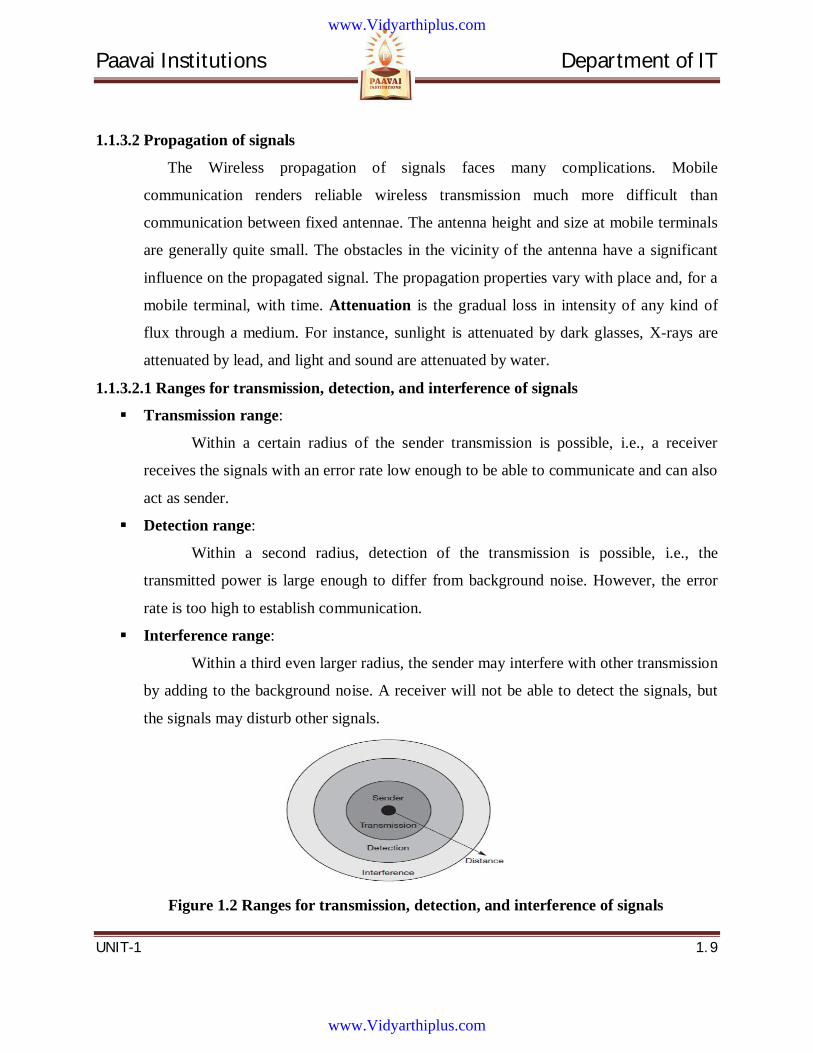
1.1.3.2.1 Ranges for transmission, detection, and interference of signals
Transmission range:
Within a certain radius of the sender transmission is possible, i.e., a receiver
receives the signals with an error rate low enough to be able to communicate and can also
act as sender.
Detection range:
Within a second radius, detection of the transmission is possible, i.e., the
transmitted power is large enough to differ from background noise. However, the error
rate is too high to establish communication.
Interference range:
Within a third even larger radius, the sender may interfere with other transmission
by adding to the background noise. A receiver will not be able to detect the signals, but
the signals may disturb other signals.
Figure 1.2 Ranges for transmission, detection, and interference of signals
www.Vidyarthiplus.com
www.Vidyarthiplus.com
Paavai Institutions Department of IT
UNIT-1 1. 10
The Signal strength
1. Decrease due to attenuation
2. When obstacles in the path of the signal greater in size than the wavelength of the
signal.
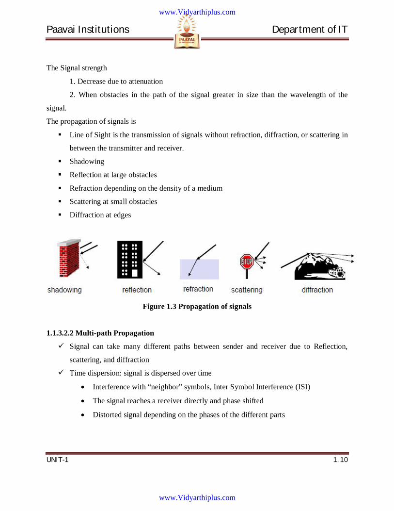
The propagation of signals is
Line of Sight is the transmission of signals without refraction, diffraction, or scattering in
between the transmitter and receiver.
Shadowing
Reflection at large obstacles
Refraction depending on the density of a medium
Scattering at small obstacles
Diffraction at edges
Figure 1.3 Propagation of signals
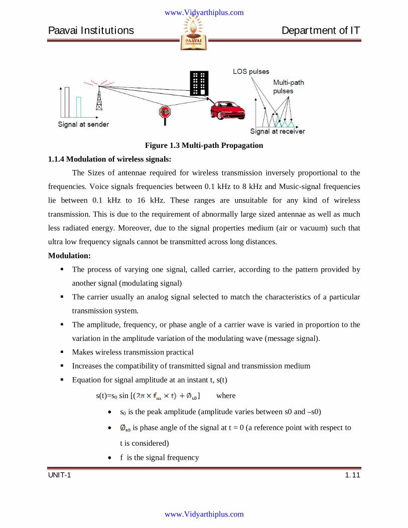
1.1.3.2.2 Multi-path Propagation
Signal can take many different paths between sender and receiver due to Reflection,
scattering, and diffraction
Time dispersion: signal is dispersed over time
Interference with “neighbor” symbols, Inter Symbol Interference (ISI)
The signal reaches a receiver directly and phase shifted
Distorted signal depending on the phases of the different parts
www.Vidyarthiplus.com
www.Vidyarthiplus.com
Paavai Institutions Department of IT
UNIT-1 1. 11
Figure 1.3 Multi-path Propagation
1.1.4 Modulation of wireless signals:
The Sizes of antennae required for wireless transmission inversely proportional to the
frequencies. Voice signals frequencies between 0.1 kHz to 8 kHz and Music-signal frequencies
lie between 0.1 kHz to 16 kHz. These ranges are unsuitable for any kind of wireless
transmission. This is due to the requirement of abnormally large sized antennae as well as much
less radiated energy. Moreover, due to the signal properties medium (air or vacuum) such that
ultra low frequency signals cannot be transmitted across long distances.
Modulation:
The process of varying one signal, called carrier, according to the pattern provided by
another signal (modulating signal)
The carrier usually an analog signal selected to match the characteristics of a particular
transmission system.
The amplitude, frequency, or phase angle of a carrier wave is varied in proportion to the
variation in the amplitude variation of the modulating wave (message signal).
Makes wireless transmission practical
Increases the compatibility of transmitted signal and transmission medium
Equation for signal amplitude at an instant t, s(t)
s(t)=s0 sin [( ] where
s0 is the peak amplitude (amplitude varies between s0 and –s0)
is phase angle of the signal at t = 0 (a reference point with respect to
t is considered)
f is the signal frequency
www.Vidyarthiplus.com
www.Vidyarthiplus.com
Paavai Institutions Department of IT
UNIT-1 1. 12
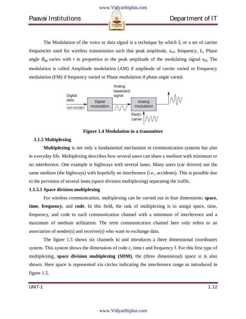
The Modulation of the voice or data signal is a technique by which fc or a set of carrier
frequencies used for wireless transmission such that peak amplitude, sc0, frequency, fc, Phase
angle varies with t in proportion to the peak amplitude of the modulating signal s(t). The
modulation is called Amplitude modulation (AM) if amplitude of carrier varied or Frequency
modulation (FM) if frequency varied or Phase modulation if phase angle varied.
Figure 1.4 Modulation in a transmitter
1.1.5 Multiplexing
Multiplexing is not only a fundamental mechanism in communication systems but also
in everyday life. Multiplexing describes how several users can share a medium with minimum or
no interference. One example is highways with several lanes. Many users (car drivers) use the
same medium (the highways) with hopefully no interference (i.e., accidents). This is possible due
to the provision of several lanes (space division multiplexing) separating the traffic.
1.1.5.1 Space division multiplexing
For wireless communication, multiplexing can be carried out in four dimensions: space,
time, frequency, and code. In this field, the task of multiplexing is to assign space, time,
frequency, and code to each communication channel with a minimum of interference and a
maximum of medium utilization. The term communication channel here only refers to an
association of sender(s) and receiver(s) who want to exchange data.
The figure 1.5 shows six channels ki and introduces a three dimensional coordinates
system. This system shows the dimensions of code c, time t and frequency f. For this first type of
multiplexing, space division multiplexing (SDM), the (three dimensional) space si is also
shown. Here space is represented via circles indicating the interference range as introduced in
figure 1.5.
www.Vidyarthiplus.com
www.Vidyarthiplus.com
Paavai Institutions Department of IT
UNIT-1 1. 13
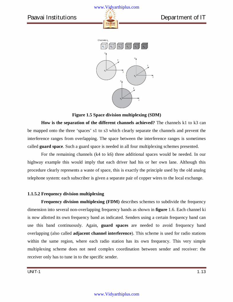
Figure 1.5 Space division multiplexing (SDM)
How is the separation of the different channels achieved? The channels k1 to k3 can
be mapped onto the three ‘spaces’ s1 to s3 which clearly separate the channels and prevent the
interference ranges from overlapping. The space between the interference ranges is sometimes
called guard space. Such a guard space is needed in all four multiplexing schemes presented.
For the remaining channels (k4 to k6) three additional spaces would be needed. In our
highway example this would imply that each driver had his or her own lane. Although this
procedure clearly represents a waste of space, this is exactly the principle used by the old analog
telephone system: each subscriber is given a separate pair of copper wires to the local exchange.
1.1.5.2 Frequency division multiplexing
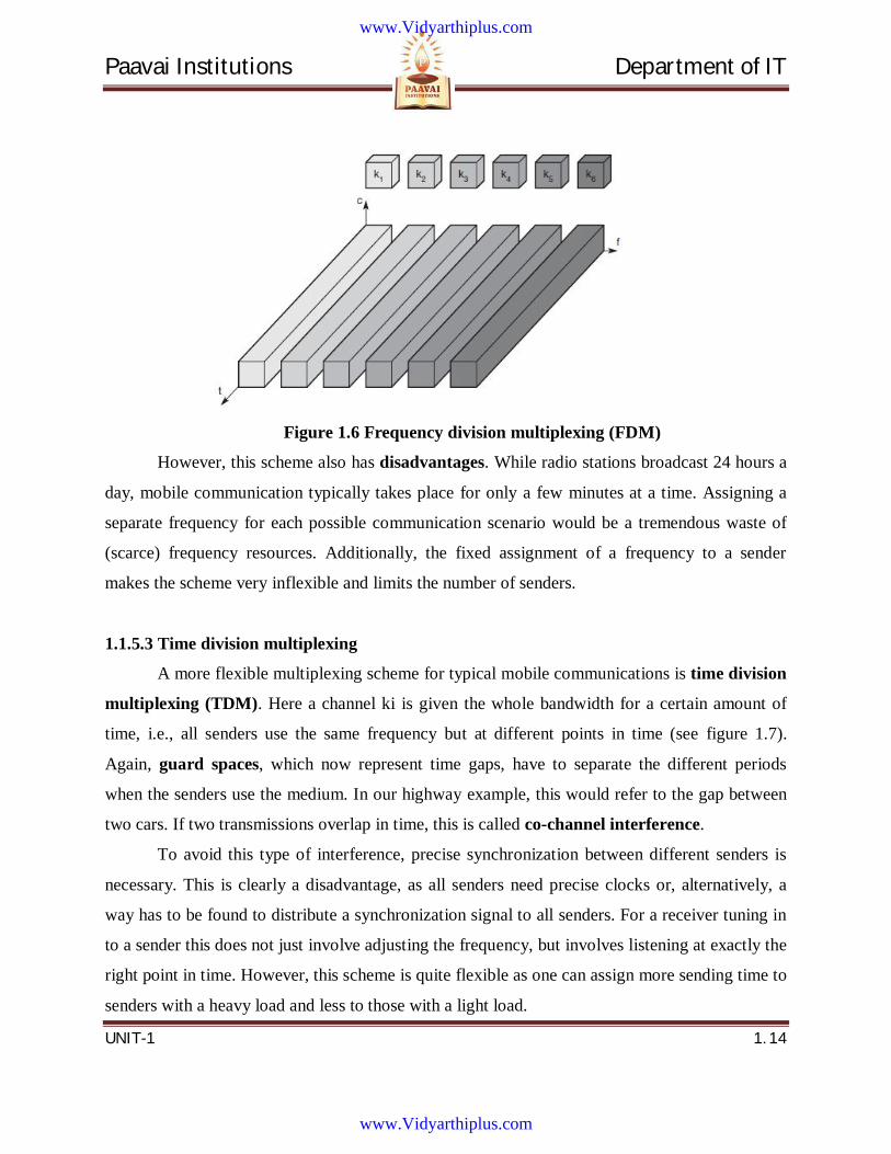
Frequency division multiplexing (FDM) describes schemes to subdivide the frequency
dimension into several non-overlapping frequency bands as shown in figure 1.6. Each channel ki
is now allotted its own frequency band as indicated. Senders using a certain frequency band can
use this band continuously. Again, guard spaces are needed to avoid frequency band
overlapping (also called adjacent channel interference). This scheme is used for radio stations
within the same region, where each radio station has its own frequency. This very simple
multiplexing scheme does not need complex coordination between sender and receiver: the
receiver only has to tune in to the specific sender.
www.Vidyarthiplus.com
www.Vidyarthiplus.com
Paavai Institutions Department of IT
UNIT-1 1. 14
Figure 1.6 Frequency division multiplexing (FDM)
However, this scheme also has disadvantages. While radio stations broadcast 24 hours a
day, mobile communication typically takes place for only a few minutes at a time. Assigning a
separate frequency for each possible communication scenario would be a tremendous waste of
(scarce) frequency resources. Additionally, the fixed assignment of a frequency to a sender
makes the scheme very inflexible and limits the number of senders.
1.1.5.3 Time division multiplexing
A more flexible multiplexing scheme for typical mobile communications is time division
multiplexing (TDM). Here a channel ki is given the whole bandwidth for a certain amount of
time, i.e., all senders use the same frequency but at different points in time (see figure 1.7).
Again, guard spaces, which now represent time gaps, have to separate the different periods
when the senders use the medium. In our highway example, this would refer to the gap between
two cars. If two transmissions overlap in time, this is called co-channel interference.
To avoid this type of interference, precise synchronization between different senders is
necessary. This is clearly a disadvantage, as all senders need precise clocks or, alternatively, a
way has to be found to distribute a synchronization signal to all senders. For a receiver tuning in
to a sender this does not just involve adjusting the frequency, but involves listening at exactly the
right point in time. However, this scheme is quite flexible as one can assign more sending time to
senders with a heavy load and less to those with a light load.
www.Vidyarthiplus.com
www.Vidyarthiplus.com
Paavai Institutions Department of IT
UNIT-1 1. 15
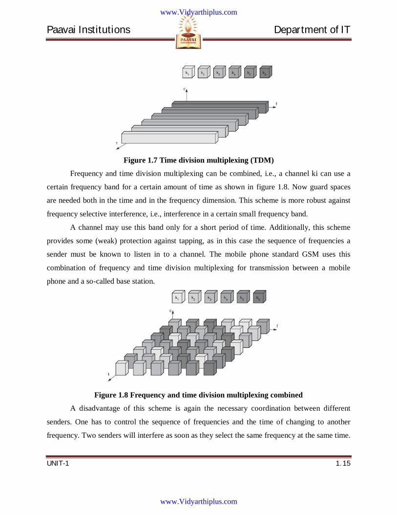
Figure 1.7 Time division multiplexing (TDM)
Frequency and time division multiplexing can be combined, i.e., a channel ki can use a
certain frequency band for a certain amount of time as shown in figure 1.8. Now guard spaces
are needed both in the time and in the frequency dimension. This scheme is more robust against
frequency selective interference, i.e., interference in a certain small frequency band.
A channel may use this band only for a short period of time. Additionally, this scheme
provides some (weak) protection against tapping, as in this case the sequence of frequencies a
sender must be known to listen in to a channel. The mobile phone standard GSM uses this
combination of frequency and time division multiplexing for transmission between a mobile
phone and a so-called base station.
Figure 1.8 Frequency and time division multiplexing combined
A disadvantage of this scheme is again the necessary coordination between different
senders. One has to control the sequence of frequencies and the time of changing to another
frequency. Two senders will interfere as soon as they select the same frequency at the same time.
www.Vidyarthiplus.com
www.Vidyarthiplus.com

Paavai Institutions Department of IT
UNIT-1 1. 16
However, if the frequency change (also called frequency hopping) is fast enough, the periods of
interference may be so small that, depending on the coding of data into signals, a receiver can
still recover the original data.
1.1.5.4 Code division multiplexing (CDM)
Code division multiplexing is by using a wide range of frequencies, called spread
spectrum. Spread spectrum has distinct set of equally separated frequencies. Different source
transmitting signals along identical path in the same time slices transmits using spread spectrum
frequencies using distinct codes.
Figure 1.9 Code division multiplexing (CDM)
Figure 1.9 shows how all channels ki use the same frequency at the same time for
transmission. Separation is now achieved by assigning each channel its own ‘code’, guard
spaces are realized by using codes with the necessary ‘distance’ in code space, e.g., orthogonal
codes. The typical everyday example of CDM is a party with many participants from different
countries around the world, who establish communication channels, i.e., they talk to each other,
using the same frequency range at the same time. If everybody speaks the same language, SDM
is needed to be able to communicate. But as soon as another code, i.e., another language, is used,
one can tune in to this language and clearly separate communication in this language from all the
other languages.
www.Vidyarthiplus.com
www.Vidyarthiplus.com
Paavai Institutions Department of IT
UNIT-1 1. 17
The main advantage of CDM for wireless transmission is that it gives good protection
against interference and tapping. Different codes have to be assigned, but code space is huge
compared to the frequency space.
The main disadvantage of this scheme is the relatively high complexity of the receiver.
A receiver has to know the code and must separate the channel with user data from the
background noise composed of other signals and environmental noise. Additionally, a receiver
must be precisely synchronized with the transmitter to apply the decoding correctly. The voice
example also gives a hint to another problem of CDM receivers. All signals should reach a
receiver with almost equal strength; otherwise some signals could drain others.
1.1.6 Introduction to 2G and 3G Data Communication Standards
First generation wireless devices only voice signals
Second generation (2G) devices communicate voice as well as data signals have
data rates of up to 14.4 kbps
The 2.5G and 2.5G+ are enhancements of the second generation and sport data
rates up to 100 kbps
Third generation (3G) mobile devices communication.
Higher data rates than 2G and support voice, data, and multimedia streams.
Facilitates data rates of 2 Mbps.
Higher for short distances.
384 kbps for long distance transmissions.
Enable transfer of video clips and faster multimedia communication
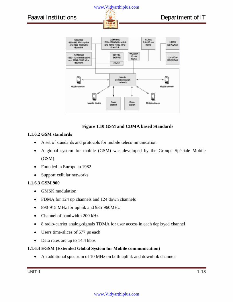
1.1.6.1 GSM and CDMA based Standards
The GSM and CDMA based Standards are mentioned in the below figure.
www.Vidyarthiplus.com
www.Vidyarthiplus.com
Paavai Institutions Department of IT
UNIT-1 1. 18
Figure 1.10 GSM and CDMA based Standards
1.1.6.2 GSM standards
A set of standards and protocols for mobile telecommunication.
A global system for mobile (GSM) was developed by the Groupe Spéciale Mobile
(GSM)
Founded in Europe in 1982
Support cellular networks
1.1.6.3 GSM 900
GMSK modulation
FDMA for 124 up channels and 124 down channels
890-915 MHz for uplink and 935-960MHz
Channel of bandwidth 200 kHz
8 radio-carrier analog-signals TDMA for user access in each deployed channel
Users time-slices of 577 µs each
Data rates are up to 14.4 kbps
1.1.6.4 EGSM (Extended Global System for Mobile communication)
An additional spectrum of 10 MHz on both uplink and downlink channels
www.Vidyarthiplus.com
www.Vidyarthiplus.com
Paavai Institutions Department of IT
UNIT-1 1. 19
1.1.6.5 EGSM 900/1800/1900 MHz tri-band
An additional spectrum of 10 MHz on both uplink and downlink channels
GSM 1800 1710–1785 MHz for uplink and 1805–1880 MHz for downlink
GSM 1900 1850–1910 MHz for uplink and 1930–1990 MHz for downlink
1.1.6.6 GPRS (General Packet Radio Service) ─GSM 2G+ (2.5G)
Packet-oriented service for data communication of mobile devices
Utilizes the unused channels in the TDMA mode in a GSM network
1.1.6.7 EDGE (Enhanced Data rates for GSM Evolution)
An enhancement GSM Phase 2.5G+]
8 PSK communication to achieve higher rates of up to 48 kbps per 200 kHz channel
High compares to up to 14.4 kbps in GSM.
Using coding techniques the rate can be enhanced to 384 kbps for the same 200 kHz
channel.
1.1.6.8 EGPRS and HSCSD
EGPRS is enhanced general packet radio service is an extension of GPRS using 8PSK
(phase shift keying) modulation
Enhances the data rate EGPRS based on EDGE
Used for HSCSD (high speed circuit switched data)
1.1.6.9 CDMA
Evolution of CDMA from 2.5G in 1991 as CDMAOne (IS-95)
CDMA supports high data rates in 3G.
Voice as well as data and multimedia streams.
CDMA 2000, IMT-2000, WCDMA and UMTS and support cellular networks
1.1.6.10 CDMAOne
Founded in 1991,QUALCOM, USA
Belongs to 2G+IS-95 (interim standards 95) and operates at 824–849 MHz and 869–
894MHz.
CDMA channel transmits analog signals from multiple sources and users
www.Vidyarthiplus.com
www.Vidyarthiplus.com
Paavai Institutions Department of IT
UNIT-1 1. 20
1.1.6.11 WCDMA
Supports asynchronous operations
10 ms frame length with 15 slices.
Smaller end-to-end delay in the 10 ms frame as compared to 20, 40, or 80 ms frames
Each frame length is modulated by QPSK both for uplink and downlink
1.1.6.12 WCDMA
DSSS CDMA
Supports a 3.84 Mbps chipping rate
Both short and long scrambling codes are supported, but for uplink only
3G partnership project (3GPP)
1.1.6.13 CDMA2000 and CDMA 2000 1x (3GPP2)
For voice communication, Circuit as well as packet switched communication.
Packet transmission uses Internet protocol (IP) for transmitting Multimedia and real time
multimedia applications
1.1.6.14 UMTS (Universal Mobile Telecommunication System)
Supports both 3GPP (3G partnership project) and 3GPP2
Communicates at data rates of 100 kbps to 2 Mbps
1.1.6.15 CDMA2000 and CDMA 2000 1x
Chipping rates are in multiples of fs = 1.2288 Mbps
3G IMT 2000 carrier frequency fc0 = 2GHz
Included in UMTS
CDMA 2000 1x fs = 1.2288 Mbps
Also backward compatible to 2.5G CDMAOne IS-95
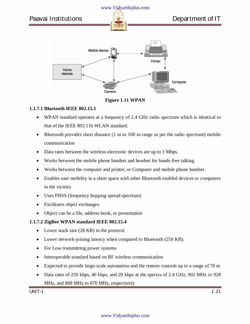
1.1.7 Introduction to WPANs and WLANs
Wireless personal area network using Bluetooth, ZigBee, or IrDA protocols
www.Vidyarthiplus.com
www.Vidyarthiplus.com
Paavai Institutions Department of IT
UNIT-1 1. 21
Figure 1.11 WPAN
1.1.7.1 Bluetooth IEEE 802.15.1
WPAN standard operates at a frequency of 2.4 GHz radio spectrum which is identical to
that of the IEEE 802.11b WLAN standard.
Bluetooth provides short distance (1 m to 100 m range as per the radio spectrum) mobile
communication
Data rates between the wireless electronic devices are up to 1 Mbps.
Works between the mobile phone handset and headset for hands-free talking
Works between the computer and printer, or Computer and mobile phone handset.
Enables user mobility in a short space with other Bluetooth enabled devices or computers
in the vicinity
Uses FHSS (frequency hopping spread spectrum)
Facilitates object exchanges
Object can be a file, address book, or presentation
1.1.7.2 ZigBee WPAN standard IEEE 802.15.4
Lower stack size (28 KB) in the protocol
Lower network-joining latency when compared to Bluetooth (250 KB).
For Low transmitting power systems
Interoperable standard based on RF wireless communication
Expected to provide large-scale automation and the remote controls up to a range of 70 m
Data rates of 250 kbps, 40 kbps, and 20 kbps at the spectra of 2.4 GHz, 902 MHz to 928
MHz, and 868 MHz to 870 MHz, respectively
www.Vidyarthiplus.com
www.Vidyarthiplus.com
Paavai Institutions Department of IT
UNIT-1 1. 22
Uses DSSS
Designed for robotic control, industrial, home, and monitoring applications.
Some of the Applications are
ZigBee enabled electric meter communicates electricity consumption data to the
mobile meter reader
A ZigBee enabled home security system alerts the mobile user of any security
breach at the home.
1.1.7.3 IrDA (infrared Data Association) 1.0
Protocol for data rates up to 115 kbps
IrDA 1.1 supports data rates of 1.152 Mbps to 4 Mbps
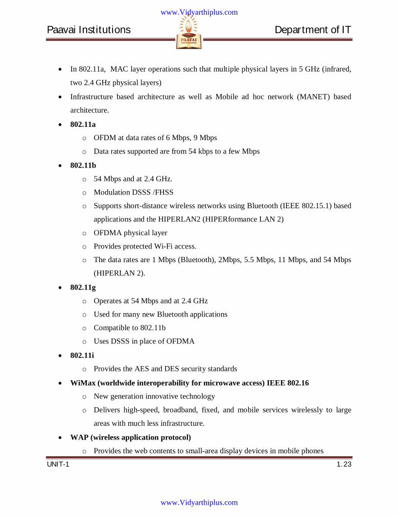
1.1.7.4 WLAN and Internet Access
IEEE 802.11a, 802.11b, and 802.11g standards
WLAN also called Wi-Fi (Wireless Fidelity).
Mobile communication using an 802.11 WLAN standard
Figure 1.12 WLAN
1.1.7.4.1 IEEE 802.11 based standards for WLANs
802.11a─ MAC layer operations such that multiple physical layers in 5 GHz (infrared,
two 2.4 GHz physical layers)
Infrastructure based architecture as well as Mobile ad hoc network (MANET) based
architecture.
Modulation is OFDM at data rates of 6 Mbps, 9 Mbps.
Data rates supported are from 54 kbps to a few Mbps.
www.Vidyarthiplus.com
www.Vidyarthiplus.com
Paavai Institutions Department of IT
UNIT-1 1. 23
In 802.11a, MAC layer operations such that multiple physical layers in 5 GHz (infrared,
two 2.4 GHz physical layers)
Infrastructure based architecture as well as Mobile ad hoc network (MANET) based
architecture.
802.11a
o OFDM at data rates of 6 Mbps, 9 Mbps
o Data rates supported are from 54 kbps to a few Mbps
802.11b
o 54 Mbps and at 2.4 GHz.
o Modulation DSSS /FHSS
o Supports short-distance wireless networks using Bluetooth (IEEE 802.15.1) based
applications and the HIPERLAN2 (HIPERformance LAN 2)
o OFDMA physical layer
o Provides protected Wi-Fi access.
o The data rates are 1 Mbps (Bluetooth), 2Mbps, 5.5 Mbps, 11 Mbps, and 54 Mbps
(HIPERLAN 2).
802.11g
o Operates at 54 Mbps and at 2.4 GHz
o Used for many new Bluetooth applications
o Compatible to 802.11b
o Uses DSSS in place of OFDMA
802.11i
o Provides the AES and DES security standards
WiMax (worldwide interoperability for microwave access) IEEE 802.16
o New generation innovative technology
o Delivers high-speed, broadband, fixed, and mobile services wirelessly to large
areas with much less infrastructure.
WAP (wireless application protocol)
o Provides the web contents to small-area display devices in mobile phones
www.Vidyarthiplus.com
www.Vidyarthiplus.com
Paavai Institutions Department of IT
UNIT-1 1. 24
o Service providers format contents in the WAP format
I-Mode (internet in mobile mode)
o Developed by NTT Do Como, Japan
o Very popular wireless Internet service for mobile phones
1.2 Mobile computing The process of computation on a mobile device
In mobile computing, a set of distributed computing systems or service provider servers
participate, connect, and synchronize through mobile communication protocols.
Mobile computing as a generic term describing ability to use the technology to wirelessly
connect to and use centrally located information and/or application software through the
application of small, portable, and wireless computing and communication devices.
Provides decentralized (distributed) computations on diversified devices, systems, and
networks, which are mobile, synchronized, and interconnected via mobile communication
standards and protocols.
Mobile device does not restrict itself to just one application, such as, voice
communication.
Offers mobility with computing power.
Facilitates a large number of applications on a single device
1.2.1 Ubiquitous computing
Refers to the blending of computing devices with environmental objects
A term that describes integration of computers into practically all objects in our everyday
environment, endowing them with computing abilities
Based on pervasive computing
1.2.2 Pervasive Computing
Pervasive means ‘existing in all parts of a place or thing’.
www.Vidyarthiplus.com
www.Vidyarthiplus.com
Paavai Institutions Department of IT
UNIT-1 1. 25
Pervasive computing─ The next generation of computing which takes into account the
environment in which information and communication technology is used everywhere,
by everyone, and at all times.
Assumes information and communication technology to be an integrated part of all facets
of our environment, such as toys, computers, cars, homes, factories, and work-areas
Takes into account the use of the integrated processors, sensors, and actuators connected
through high-speed networks and combined with new devices for viewing and display.
Mobile Computing is also called pervasive computing when a set of computing devices,
systems, or networks have the characteristics of transparency, application-aware
adaptation, and have an environment sensing ability
Pervasive computing devices are not PCs, are handheld, very tiny, or even invisible
devices which are either mobile or embedded in almost any type of object.
1.2.3 Limitations to mobile computing
Resource constraints: Battery
Interference: the quality of service (QoS)
Bandwidth: connection latency
Dynamic changes in communication environment: variations in signal power within a
region, thus link delays and connection losses
Network Issues: discovery of the connection-service to destination and connection
stability
Interoperability issues: the varying protocol standards
Security constraints: Protocols conserving privacy of communication
1.3 Mobile Computing Architecture Programming languages used for mobile system software. Operating system functions to
run the software components onto the hardware. Middleware components deployment Layered
structure arrangement of mobile computing components. Protocols and layers used for
transmission and reception.
www.Vidyarthiplus.com
www.Vidyarthiplus.com
Paavai Institutions Department of IT
UNIT-1 1. 26
Some of the Programming Languages are Java, J2SE, J2ME (Java2 Micro edition), Java
Card (Java for smart card. The Java enterprise edition (J2EE) used for web and enterprise server
based applications of mobile services C and C++, Visual C++, Visual Basic.
1.3.1 Functions of Operating System
Operating Systems are Symbian OS, Window CE, Mac OS. It offers the user to run an
application without considering the hardware specifications and functionalities. It provides
functions which are used for scheduling the multiple tasks in a system. It provides the functions
required for the synchronization of multiple tasks in the system and multiple threads
synchronization and priority allocation.
Management functions (such as creation, activation, deletion, suspension, and delay) for
tasks and memory. It provides Interfaces for communication between software components at the
application layer, middleware layers, and hardware devices. It facilitates execution of software
components on diversified hardware. It provides Configurable libraries for the GUI (graphic user
interface) in the device. It Provides User application’s GUIs, VUI (voice user interface)
components, and phone API.
1.3.2 Middleware for Mobile Systems
Middleware are the software components that link the application components with the
network-distributed components.
Examples of Middleware Applications are:
To discover the nearby device such as Bluetooth
To discover the nearby hot spot.
To achieving device synchronization with the server or an enterprise server
For retrieving data (which may be in Oracle or DB2) from a network database
For service discovery at network
For adaptation of the application to the platform and service availability
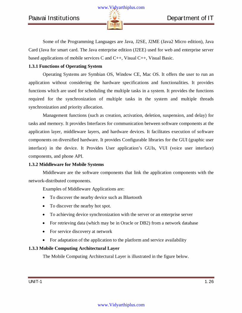
1.3.3 Mobile Computing Architectural Layer
The Mobile Computing Architectural Layer is illustrated in the figure below.
www.Vidyarthiplus.com
www.Vidyarthiplus.com
Paavai Institutions Department of IT
UNIT-1 1. 27
Figure 1.13 Mobile Computing Architectural Layer
1.3.4 Protocols
Some of the protocols are WAP, GSM 900, GSM900/1800/1900, UMTS, and I-Mode.
Some of the WPAN protocols are Bluetooth, IrDA, and Zigbee. Some of the WLAN protocols
802.11a and 802.11b.
1.3.5 Mobile Computing system Layers
1. Physical for sending and receiving signals (for example, TDMA or CDMA coding)
2. Data-link (for example, multiplexing)
3. Networking (for linking to the destination)
4. Wireless transport layer security (for establishing end-to-end connectivity)
5. Wireless transaction protocol
6. Wireless session protocol
7. Wireless application environment (Running a web application, for e.g., mobile e-
business).
www.Vidyarthiplus.com
www.Vidyarthiplus.com
Paavai Institutions Department of IT
UNIT-1 1. 28
1.5 Mobile Devices
A mobile device (also known as a handheld device, handheld computer or simply
handheld) is a small, hand-held computing device, typically having a display screen with touch
input and/or a miniature keyboard and weighing less than 2 pounds (0.91 kg). Apple, HTC, LG,
Motorola, Research in Motion (RIM), and Samsung are just a few examples of the many
manufacturers that produce these types of devices.
A handheld computing device has an operating system (OS), and can run various types of
application software, known as apps. Most hand held devices can also be equipped with WI-FI,
Bluetooth and GPS capabilities that can allow connections to the Internet and other Bluetooth
capable devices such as an automobile or a microphone headset. A camera or media player
feature for video or music files can also be typically found on these devices along with a stable
battery power source such as a lithium battery.
Early pocket sized ones were joined in the late 2000s by larger but otherwise similar
tablet computers. As in a personal digital assistant (PDA), the input and output are often
combined into a touch-screen interface.
Smart phones and PDAs are popular amongst those who wish to use some of the powers
of a conventional computer in environments where carrying one would not be practical.
Enterprise digital assistants can further extend the available functionality for the business user by
offering integrated data capture devices like barcode, RFID and smart card readers
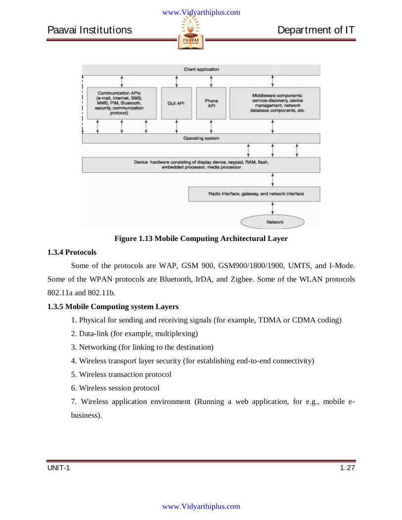
1.5 Mobile System Networks • Cellular networks
A cell is the coverage area of a base station, connected to other stations via wire
or fiber or wirelessly through switching centers. Each cell base station functions as an
access point for the mobile service. Each mobile device connects to the base station of the
cell which covers the current location of the device. All the mobile devices within the
range of a given base station communicate with each other through that base station only.
www.Vidyarthiplus.com
www.Vidyarthiplus.com
Paavai Institutions Department of IT
UNIT-1 1. 29
Figure 1.14 Cellular Networks
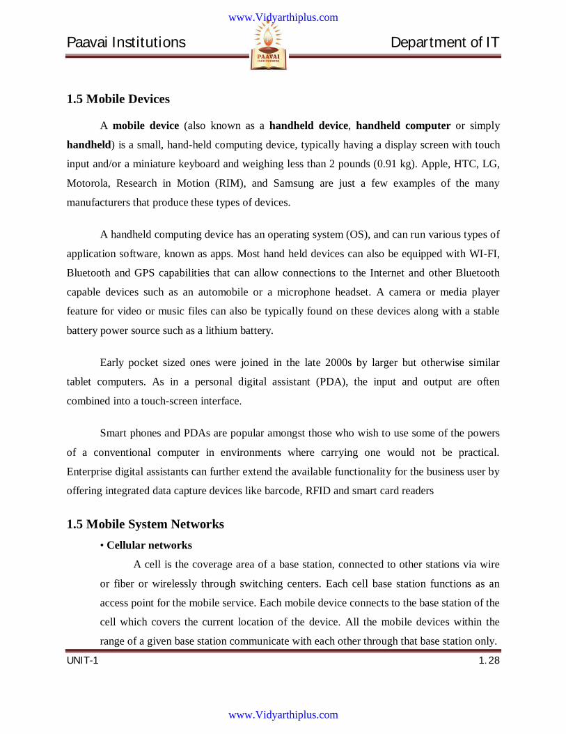
• WLAN networks and Mobile IP:
For connectivity between the Internets, two LANs, mobile devices, and computers
are needed. Mobile device connects to an access point, called a hot spot. The access
point, in turn, connects to a host LAN which links up to the Internet through a router.
Mobile IP is an open standard based on the IP (internet protocol). Mobile IP network
provides the mobile IP service using home agents and foreign agents.
Figure 1.15 Communication between mobile devices using a WLAN network through hot-
spots.
www.Vidyarthiplus.com
www.Vidyarthiplus.com
Paavai Institutions Department of IT
UNIT-1 1. 30
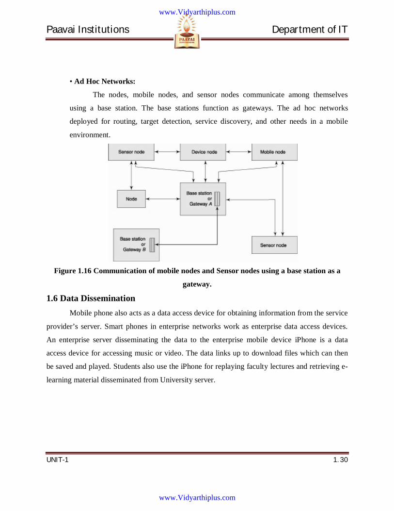
• Ad Hoc Networks:
The nodes, mobile nodes, and sensor nodes communicate among themselves
using a base station. The base stations function as gateways. The ad hoc networks
deployed for routing, target detection, service discovery, and other needs in a mobile
environment.
Figure 1.16 Communication of mobile nodes and Sensor nodes using a base station as a
gateway.
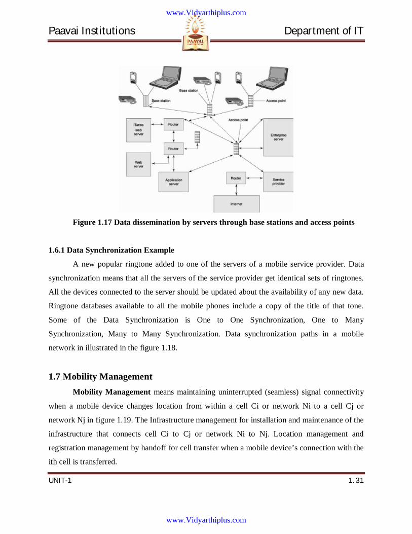
1.6 Data Dissemination Mobile phone also acts as a data access device for obtaining information from the service
provider’s server. Smart phones in enterprise networks work as enterprise data access devices.
An enterprise server disseminating the data to the enterprise mobile device iPhone is a data
access device for accessing music or video. The data links up to download files which can then
be saved and played. Students also use the iPhone for replaying faculty lectures and retrieving e-
learning material disseminated from University server.
www.Vidyarthiplus.com
www.Vidyarthiplus.com
Paavai Institutions Department of IT
UNIT-1 1. 31
Figure 1.17 Data dissemination by servers through base stations and access points
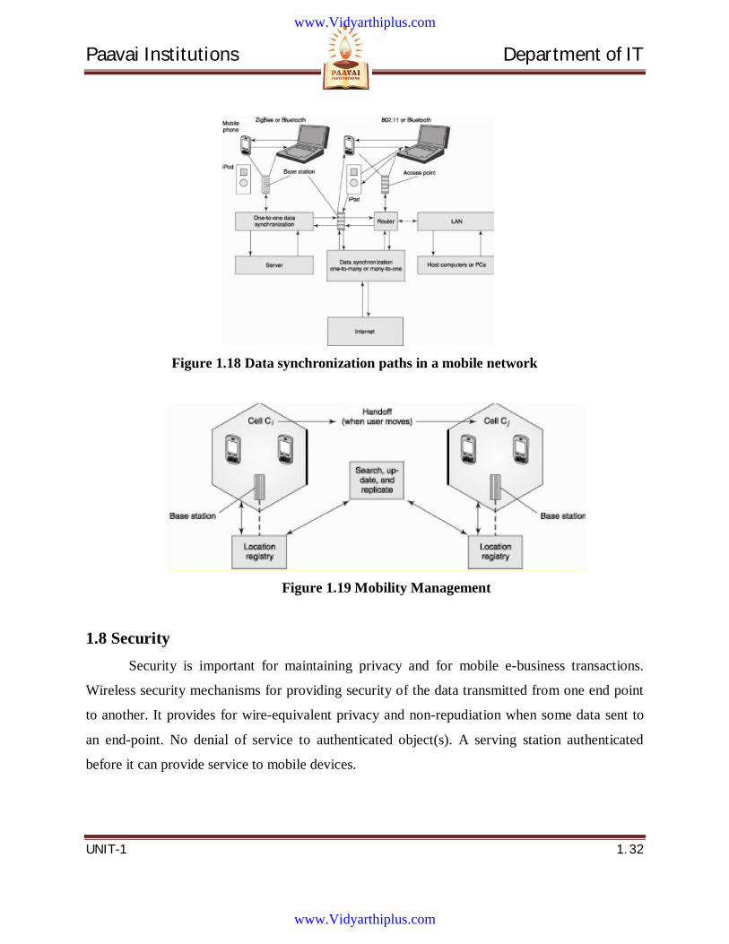
1.6.1 Data Synchronization Example
A new popular ringtone added to one of the servers of a mobile service provider. Data
synchronization means that all the servers of the service provider get identical sets of ringtones.
All the devices connected to the server should be updated about the availability of any new data.
Ringtone databases available to all the mobile phones include a copy of the title of that tone.
Some of the Data Synchronization is One to One Synchronization, One to Many
Synchronization, Many to Many Synchronization. Data synchronization paths in a mobile
network in illustrated in the figure 1.18.
1.7 Mobility Management Mobility Management means maintaining uninterrupted (seamless) signal connectivity
when a mobile device changes location from within a cell Ci or network Ni to a cell Cj or
network Nj in figure 1.19. The Infrastructure management for installation and maintenance of the
infrastructure that connects cell Ci to Cj or network Ni to Nj. Location management and
registration management by handoff for cell transfer when a mobile device’s connection with the
ith cell is transferred.
www.Vidyarthiplus.com
www.Vidyarthiplus.com
Paavai Institutions Department of IT
UNIT-1 1. 32
Figure 1.18 Data synchronization paths in a mobile network
Figure 1.19 Mobility Management
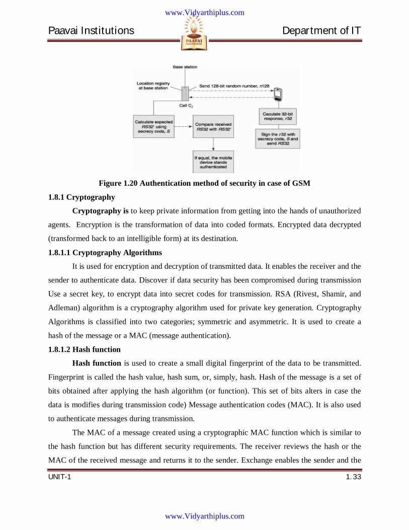
1.8 Security Security is important for maintaining privacy and for mobile e-business transactions.
Wireless security mechanisms for providing security of the data transmitted from one end point
to another. It provides for wire-equivalent privacy and non-repudiation when some data sent to
an end-point. No denial of service to authenticated object(s). A serving station authenticated
before it can provide service to mobile devices.
www.Vidyarthiplus.com
www.Vidyarthiplus.com
Paavai Institutions Department of IT
UNIT-1 1. 33
Figure 1.20 Authentication method of security in case of GSM
1.8.1 Cryptography
Cryptography is to keep private information from getting into the hands of unauthorized
agents. Encryption is the transformation of data into coded formats. Encrypted data decrypted
(transformed back to an intelligible form) at its destination.
1.8.1.1 Cryptography Algorithms
It is used for encryption and decryption of transmitted data. It enables the receiver and the
sender to authenticate data. Discover if data security has been compromised during transmission
Use a secret key, to encrypt data into secret codes for transmission. RSA (Rivest, Shamir, and
Adleman) algorithm is a cryptography algorithm used for private key generation. Cryptography
Algorithms is classified into two categories; symmetric and asymmetric. It is used to create a
hash of the message or a MAC (message authentication).
1.8.1.2 Hash function
Hash function is used to create a small digital fingerprint of the data to be transmitted.
Fingerprint is called the hash value, hash sum, or, simply, hash. Hash of the message is a set of
bits obtained after applying the hash algorithm (or function). This set of bits alters in case the
data is modifies during transmission code) Message authentication codes (MAC). It is also used
to authenticate messages during transmission.
The MAC of a message created using a cryptographic MAC function which is similar to
the hash function but has different security requirements. The receiver reviews the hash or the
MAC of the received message and returns it to the sender. Exchange enables the sender and the
www.Vidyarthiplus.com
www.Vidyarthiplus.com

Paavai Institutions Department of IT
UNIT-1 1. 34
receiver to find out if the message has been tampered with and thus helps verify message
integrity and authenticity.
1.8.1.3 Data encryption standard (DES)
DES uses 56-bits for a key plus 8 bits for parity. Block length 64 bit. [Maximum block
size = 264 bits
1.8.1.4 Triple DES
Triple DES an enhance version of DES. Multiple encryptions or encryption-decryption-
encryption steps in the cryptic message are a different key at each step for cryptic message
creation.
1.8.1.5 Advanced encryption standard (AES)
There are nine possible combinations of key lengths and block lengths. The key-length
can be 128, 192, or 256 bits. The block lengths can also be 128, 192, or 256 bits. Block length of
128 bits means maximum block length = 2128 bits.
1.8.1.6 RSA─ The Asymmetric key based standard
The RSA (Rivest, Shamir, Alderman) algorithm uses 128, 256, 512, or 1024 bit prime
numbers for encryption
1.8.1.7 DSA (digital signature algorithm)
DSA is used to sign a record before transmitting. DSA provides for a variable key length
of maximum 512 or 1024 bits
1.8.1.8 DSS (digital signature standard)
DSS is based on the DSA. Signature enables identification of the sender, identifies the
origin of the message, and checks the message integrity.
1.8.1.9 Digital certificate
An electronic certificate used to establish the credentials of a data set. Issued by a
certification authority and contains the certificate holder's name, a copy of the certificate holder's
public key, a serial number, and expiration dates. It includes the digital signature of the
certificate-issuing authority for verification of the authenticity of the certificate. The certification
authority distributes a digital certificate, which binds a public key to a specific sender.
www.Vidyarthiplus.com
www.Vidyarthiplus.com
Paavai Institutions Department of IT
UNIT-1 1. 35
1.9 Introduction to Cellular systems: Geographic region is subdivided in radio cells. Base Station provides radio connectivity
to Mobile Station within cell. Handover to neighboring base station when necessary. Base
Stations connected by some networking infrastructure.
Figure 1.21 Cellular Networks
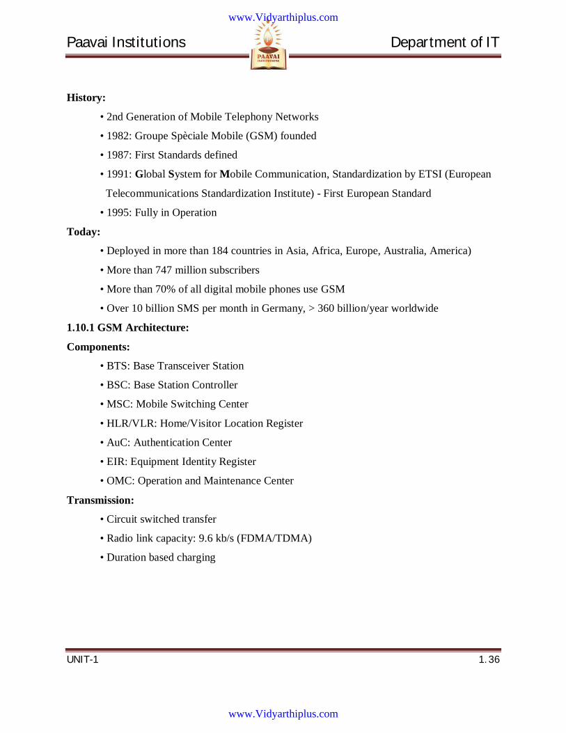
1.9.1 Cellular systems: technologies & subscribers
The usage of cellular systems is represented in graph as shown below.
Figure 1.22 Cellular systems: technologies & subscribers
1.10 GSM: Global System for Mobile Communication GSM is a set of standards and protocols for mobile telecommunication. A global system for
mobile (GSM) was developed by the Groupe Spéciale Mobile (GSM) and it was founded in
Europe in 1982. It supports cellular networks.
www.Vidyarthiplus.com
www.Vidyarthiplus.com
Paavai Institutions Department of IT
UNIT-1 1. 36
History:
• 2nd Generation of Mobile Telephony Networks
• 1982: Groupe Spèciale Mobile (GSM) founded
• 1987: First Standards defined
• 1991: Global System for Mobile Communication, Standardization by ETSI (European
Telecommunications Standardization Institute) - First European Standard
• 1995: Fully in Operation
Today:
• Deployed in more than 184 countries in Asia, Africa, Europe, Australia, America)
• More than 747 million subscribers
• More than 70% of all digital mobile phones use GSM
• Over 10 billion SMS per month in Germany, > 360 billion/year worldwide
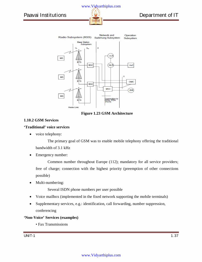
1.10.1 GSM Architecture:
Components:
• BTS: Base Transceiver Station
• BSC: Base Station Controller
• MSC: Mobile Switching Center
• HLR/VLR: Home/Visitor Location Register
• AuC: Authentication Center
• EIR: Equipment Identity Register
• OMC: Operation and Maintenance Center
Transmission:
• Circuit switched transfer
• Radio link capacity: 9.6 kb/s (FDMA/TDMA)
• Duration based charging
www.Vidyarthiplus.com
www.Vidyarthiplus.com
Paavai Institutions Department of IT
UNIT-1 1. 37
Figure 1.23 GSM Architecture
1.10.2 GSM Services
‘Traditional’ voice services
voice telephony:
The primary goal of GSM was to enable mobile telephony offering the traditional
bandwidth of 3.1 kHz
Emergency number:
Common number throughout Europe (112); mandatory for all service providers;
free of charge; connection with the highest priority (preemption of other connections
possible)
Multi-numbering:
Several ISDN phone numbers per user possible
Voice mailbox (implemented in the fixed network supporting the mobile terminals)
Supplementary services, e.g.: identification, call forwarding, number suppression,
conferencing
‘Non-Voice’ Services (examples)
• Fax Transmissions
www.Vidyarthiplus.com
www.Vidyarthiplus.com
Paavai Institutions Department of IT
UNIT-1 1. 38
• Electronic mail (MHS, Message Handling System, implemented in the fixed network)
• Short Message Service (SMS):
Alphanumeric data transmission to/from the mobile terminal using the signaling
channel, thus allowing simultaneous use of basic services and SMS.
1.10.3 GSM: Radio Technology
Cellular Concept:
The segmentation of geographical area into divided cells. Cell sizes vary from some 100
m up to 35 km depending on user density, geography, transceiver power etc. The hexagonal
shape of cells is idealized (cells overlap, shapes depend on geography). The use of several carrier
frequencies avoids same frequency in adjoining cells. If a mobile user changes cells, handover of
the connection to the neighbor cell takes place.
1.11 GPRS: General Packet Radio Service GRS is Packet Switched Extension of GSM. In 1996, new standard developed by ETSI
Components are integrated in GSM architecture.
Some of the Improvements are:
Packet-switched transmission
Higher transmission rates on radio link (multiple time-slots)
Volume based charging ‚Always ON‘ mode possible
Operation started in 2001 (Germany)
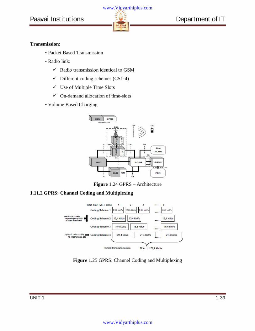
1.11.1 GPRS – Architecture
Components:
• CCU: Channel Coding Unit
• PCU: Packet Control Unit
• SGSN: Serving GPRS Support Node
• GGSN: Gateway GPRS Support Node
• GR: GPRS Register
www.Vidyarthiplus.com
www.Vidyarthiplus.com
Paavai Institutions Department of IT
UNIT-1 1. 39
Transmission:
• Packet Based Transmission
• Radio link:
Radio transmission identical to GSM
Different coding schemes (CS1-4)
Use of Multiple Time Slots
On-demand allocation of time-slots
• Volume Based Charging
Figure 1.24 GPRS – Architecture
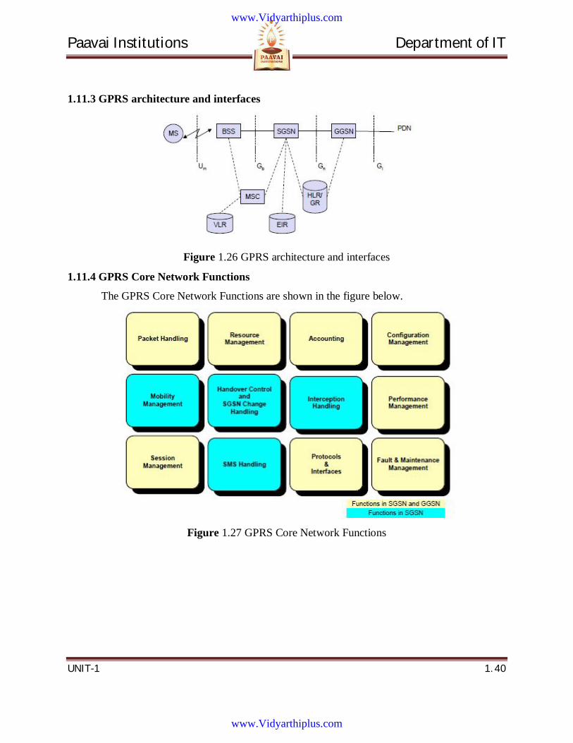
1.11.2 GPRS: Channel Coding and Multiplexing
Figure 1.25 GPRS: Channel Coding and Multiplexing
www.Vidyarthiplus.com
www.Vidyarthiplus.com
Paavai Institutions Department of IT
UNIT-1 1. 40
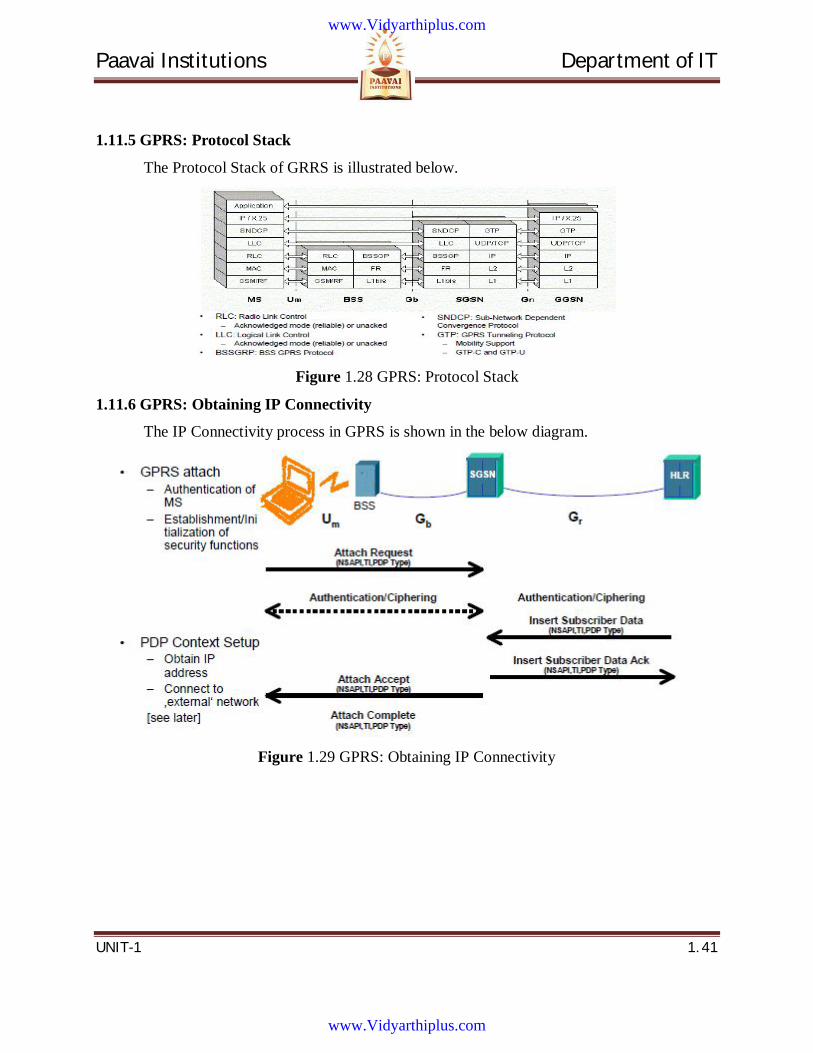
1.11.3 GPRS architecture and interfaces
Figure 1.26 GPRS architecture and interfaces
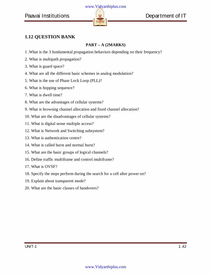
1.11.4 GPRS Core Network Functions
The GPRS Core Network Functions are shown in the figure below.
Figure 1.27 GPRS Core Network Functions
www.Vidyarthiplus.com
www.Vidyarthiplus.com
Paavai Institutions Department of IT
UNIT-1 1. 41
1.11.5 GPRS: Protocol Stack
The Protocol Stack of GRRS is illustrated below.
Figure 1.28 GPRS: Protocol Stack
1.11.6 GPRS: Obtaining IP Connectivity
The IP Connectivity process in GPRS is shown in the below diagram.
Figure 1.29 GPRS: Obtaining IP Connectivity
www.Vidyarthiplus.com
www.Vidyarthiplus.com
Paavai Institutions Department of IT
UNIT-1 1. 42
1.12 QUESTION BANK PART – A (2MARKS)
1 .What is the 3 fundamental propagation behaviors depending on their frequency?
2. What is multipath propagation?
3. What is guard space?
4. What are all the different basic schemes in analog modulation?
5. What is the use of Phase Lock Loop (PLL)?
6. What is hopping sequence?
7. What is dwell time?
8. What are the advantages of cellular systems?
9. What is browsing channel allocation and fixed channel allocation?
10. What are the disadvantages of cellular systems?
11. What is digital sense multiple access?
12. What is Network and Switching subsystem?
13. What is authentication centre?
14. What is called burst and normal burst?
15. What are the basic groups of logical channels?
16. Define traffic multiframe and control multiframe?
17. What is OVSF?
18. Specify the steps perform during the search for a cell after power on?
19. Explain about transparent mode?
20. What are the basic classes of handovers?
www.Vidyarthiplus.com
www.Vidyarthiplus.com
Paavai Institutions Department of IT
UNIT-1 1. 43
PART – B (16 MARKS)
1. Discuss briefly the multiplexing techniques.
2. Explain about the signal propagation.
3. Discuss about the cellular system.
4. List the difference between S/T/F/CDMA.
5. What is spread spectrum with its types.
6. Explain about the TDMA.
7. Why CDMA is needed and explain it with an example?
8. Why do MAC scheme in wired network fail in wireless networks and how does the multiple
access with collision avoidance (MACA) scheme work.
9. Define modulation and explain the method for analog modulation techniques in details.
10. Discuss briefly the code division multiplexing techniques.
11. Discuss briefly the advanced phase shift keying.
www.Vidyarthiplus.com
www.Vidyarthiplus.com

Paavai Institutions Department of IT
UNIT-2 2. 1
UNIT 2
WIRELESS MEDIUM ACCESS CONTROL
www.Vidyarthiplus.com
www.Vidyarthiplus.com
Paavai Institutions Department of IT
UNIT-2 2. 2
CONTENTS
2.1 Interference in cellular system
2.2 Frequency management
2.3 Channel Assignment
2.4 Location management in cellular networks
2.4.1 Mobility Management
2.5 Medium Access Control (MAC)
2.5.1 Preamble
2.5.2 Header
2.5.3 CRC
2.5.4 Inter Frame Gap
2.5.5 Byte Order
2.5.6 CSMA /CD
2.5.7 Receiver Processing Algorithm
2.5.8 Runt Frame
2.5.9 Giant Frame
2.5.10 Jumbo Frame
2.5.11 Misaligned Frame
2.5.12 Other Issues
2.6 Introduction to CDMA based systems
2.6.1 Spread Spectrum in CDMA systems
2.6.2 Three Types of Spread Spectrum Communications
2.6.3 Direct Sequence Spread Spectrum
2.7 Coding Methods in CDMA
2.7.1 Input data
2.7.2 Generating Pseudo-Random Codes
2.7.3 Pseudo-Noise Spreading
2.7.4 Transmitting Data
2.7.5 Working with Complex Data
www.Vidyarthiplus.com
www.Vidyarthiplus.com
Paavai Institutions Department of IT
UNIT-2 2. 3
2.7.6 Summing Many Channels Together
2.7.7 Receiving Data
2.8 Question Bank
www.Vidyarthiplus.com
www.Vidyarthiplus.com
Paavai Institutions Department of IT
UNIT-2 2. 4
TECHNICAL TERMS
1. Cellular System: In a Cellular System, a cell is the coverage area of a base station,
connected to other stations via wire or fiber or wirelessly through switching centers.
2. Interference is anything which alters, modifies, or disrupts a signal as it travels along a
channel between a source and a receiver.
3. Interface is a tool and concept that refers to a point of interaction between components,
and is applicable at the level of both hardware and software.
4. Beacon contains a timestamp and other management information used for power
management and roaming. e.g., identification of the base station subsystem (BSS)
5. Frequency Management The requesting, recording, deconfliction of and issuance of
authorization to use frequencies (operate electromagnetic spectrum dependent systems)
coupled with monitoring and interference resolution processes.
6. Mobile terminals (MT) are platforms that allow the broadcasting of television programs
with their multimedia content and for the digital transmission of data and communication
based on Internet Protocol. These include cellular phones, portable digital players,
computer tablets, wireless game consoles, etc. They are by definition digital since they
are used to send and receive data
7. Location Management locates MTs with the main purposes to deliver incoming calls to
them at a reasonable cost.
8. Handover: The term handover or handoff refers to the process of transferring an ongoing
call or data session from one channel connected to the core network to another.
9. Handoff or Handover Management transfers ongoing calls to adjacent cells as a MT
moves from one access point in the network to another
10. Medium Access Control (MAC): data communication protocol is a sub layer of the data
link layer, which itself is layer 2. The MAC sub layer provides addressing and channel
access control mechanisms that make it possible for several terminals or network nodes
to communicate within a multiple access network that incorporates a shared medium,
e.g. Ethernet. It is also referred to as a medium access controller.
www.Vidyarthiplus.com
www.Vidyarthiplus.com
Paavai Institutions Department of IT
UNIT-2 2. 5
11. Polling Cycle is the process which is done by the network when a call arrives to a MT,
The network send Polling signal to target cell in the Residing area and wait for response.
12. Spread Spectrum has distinct set of equally separated frequencies.
13. Subscriber is the term used to refer to a person that has an account with a mobile
network carrier. They are called such because they subscribe to the carrier's mobile phone
services.
www.Vidyarthiplus.com
www.Vidyarthiplus.com
Paavai Institutions Department of IT
UNIT-2 2. 6
2. WIRELESS MEDIUM ACCESS CONTROL
2.1 Interference in cellular system As wireless systems proliferate worldwide, the number one enemy of wireless systems
designers and service providers is signal interference. Interference hampers coverage and
capacity, and limits the effectiveness of both new and existing systems. It is an unavoidable fact
that wireless communications systems must coexist in extremely complicated signal
environments. These environments are comprised of multiple operating wireless networks
ranging from mobile communication services to specialized mobile radio and paging/broadcast
systems. At the same time, wireless local area networks (WLANs) and digital video broadcasting
are introducing new technologies and signal sources that further threaten to disrupt wireless
communications service.
Compounding the problem are regulatory and environmental restrictions which have
effectively limited the number of suitable new base station transceiver sites that can be put in
place. Hence, many wireless service providers are now faced with co-location issues further
contributing to the potential for signal interference as more antennae are placed on individual cell
towers. This application note presents the subject of interference and its degrading effects on the
performance of wireless networks. It provides a brief theory of operation of communications
receivers and antennae, as well as instructions on how to locate and identify an interfering signal.
It also reviews the operating principles of the Anritsu Spectrum Master MS2711B and some of
its functional routines which make it an ideal interference troubleshooting tool.
Interference:
Interference is, anything which alters, modifies, or disrupts a message as it travels along a channel
Electromagnetic interference (EMI)
Co-channel interference (CCI), also known as crosstalk
Adjacent-channel interference (ACI), interference caused by extraneous power from a signal
in an adjacent channel
www.Vidyarthiplus.com
www.Vidyarthiplus.com
Paavai Institutions Department of IT
UNIT-2 2. 7
Intersymbol interference (ISI), distortion of a signal in which one symbol interferes with
subsequent symbols
Inter-carrier interference (ICI), caused by doppler shift in OFDM modulation
2.2 Frequency management Unlike a traditional client-server network, a mobile computing environment has a
very limited bandwidth in a wireless link.
Thus, one design goal of caching management in a mobile computing
environment is to reduce the use of wireless links.
Quota data and private data mechanisms are used in our design so that an MU
user is able to query and update data from the local DBMS without cache
coherence problems.
The effect of the two mechanisms is to increase the hit ratio. An agent on an MU
along with a program on a base station are used to handle the caching
management, including prefetching/hoarding, cache use, cache replacement, and
cache-miss handling.
The simulation results clearly indicate that our approaches are improvements to
the previous research.
2.3 Channel Assignment
Frequency allocation should be carefully planned to avoid degradation caused by
co-channel interference
Fixed channel assignment, dynamic channel assignment, and hybrid channel
assignment are the types of channel assignment.
Classification of channel assignment are
1. Fixed Channel Assignment
2. Dynamic Channel Assignment
3. Hybrid Channel Assignment
4. FCA with Borrowing
www.Vidyarthiplus.com
www.Vidyarthiplus.com
Paavai Institutions Department of IT
UNIT-2 2. 8
5. Directed Retry
6. Load Sharing
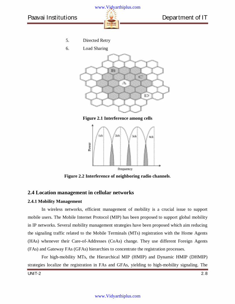
Figure 2.1 Interference among cells
Figure 2.2 Interference of neighboring radio channels.
2.4 Location management in cellular networks 2.4.1 Mobility Management
In wireless networks, efficient management of mobility is a crucial issue to support
mobile users. The Mobile Internet Protocol (MIP) has been proposed to support global mobility
in IP networks. Several mobility management strategies have been proposed which aim reducing
the signaling traffic related to the Mobile Terminals (MTs) registration with the Home Agents
(HAs) whenever their Care-of-Addresses (CoAs) change. They use different Foreign Agents
(FAs) and Gateway FAs (GFAs) hierarchies to concentrate the registration processes.
For high-mobility MTs, the Hierarchical MIP (HMIP) and Dynamic HMIP (DHMIP)
strategies localize the registration in FAs and GFAs, yielding to high-mobility signaling. The
www.Vidyarthiplus.com
www.Vidyarthiplus.com
Paavai Institutions Department of IT
UNIT-2 2. 9
Multicast HMIP strategy limits the registration processes in the GFAs. For high-mobility MTs, it
provides lowest mobility signaling delay compared to the HMIP and DHMIP approaches.
However, it is resource consuming strategy unless for frequent MT mobility.
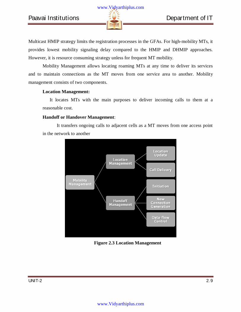
Mobility Management allows locating roaming MTs at any time to deliver its services
and to maintain connections as the MT moves from one service area to another. Mobility
management consists of two components.
Location Management:
It locates MTs with the main purposes to deliver incoming calls to them at a
reasonable cost.
Handoff or Handover Management:
It transfers ongoing calls to adjacent cells as a MT moves from one access point
in the network to another
Figure 2.3 Location Management
www.Vidyarthiplus.com
www.Vidyarthiplus.com

Paavai Institutions Department of IT
UNIT-2 2. 10
Figure 2.4 Hand off or Handover Management
Location Update schemes
Location Update (LU) schemes are classified in two main groups:
Static or global schemes:
LU is triggered based on the topology of the network.
Dynamic or local schemes:
An MT sends a LU message according to the time elapsed (time-based method), the
number of cells visited (movement-based method), or the distance -in terms of cells-
travelled (distance-based method) to the node in the cellular network.
Movement Based LU Schemes
In Movement Based Schemes:
Each MT only keeps a counter of the number of cells visited
A location update is performed when this counter exceeds a predefined threshold
value
Center Cell is the cell where the last location update occurred
Residing Area of the MT is the area in which the mobile can be located and this area is
within a maximum distance of d - 1 from the center cell
www.Vidyarthiplus.com
www.Vidyarthiplus.com

Paavai Institutions Department of IT
UNIT-2 2. 11
Figure 2.5 Location Update schemes
Polling Cycle
The process which is done by the network when a call arrives to a MT, The
network send Polling signal to target cell in the residing area and wait for
response
Movement Based Location Update
The movement based LU is performed by a mobile terminal when the number of
cell boundary crossings since the last location registration equals a threshold
value.
2.5 Medium Access Control (MAC) MAC is a data communication protocol. It is a sub layer of the data link layer, which
itself is layer 2. The MAC sub layer provides addressing and channel access control mechanisms
that make it possible for several terminals or network nodes to communicate within a multiple
www.Vidyarthiplus.com
www.Vidyarthiplus.com
Paavai Institutions Department of IT
UNIT-2 2. 12
access network that incorporates a shared medium, e.g. Ethernet. It is also referred to as
a medium access controller. 2.5.1 Preamble
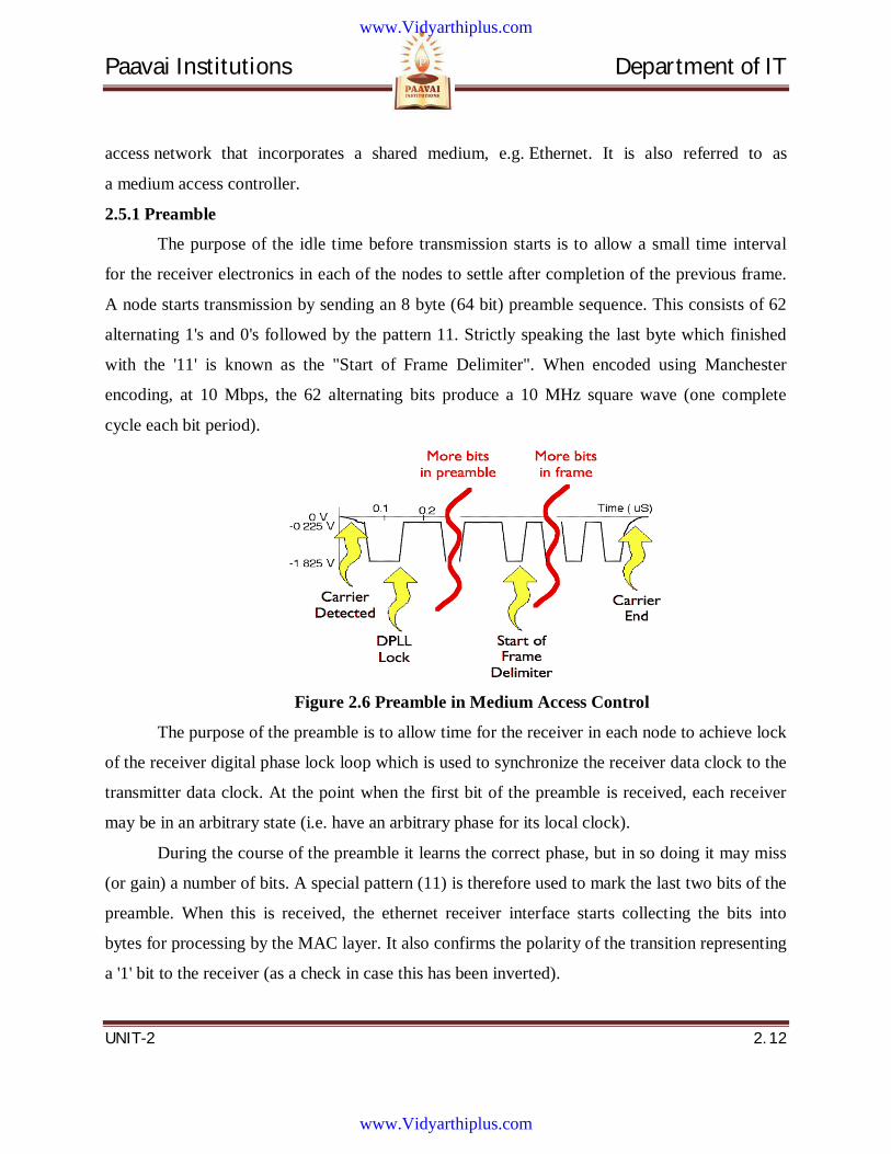
The purpose of the idle time before transmission starts is to allow a small time interval
for the receiver electronics in each of the nodes to settle after completion of the previous frame.
A node starts transmission by sending an 8 byte (64 bit) preamble sequence. This consists of 62
alternating 1's and 0's followed by the pattern 11. Strictly speaking the last byte which finished
with the '11' is known as the "Start of Frame Delimiter". When encoded using Manchester
encoding, at 10 Mbps, the 62 alternating bits produce a 10 MHz square wave (one complete
cycle each bit period).
Figure 2.6 Preamble in Medium Access Control
The purpose of the preamble is to allow time for the receiver in each node to achieve lock
of the receiver digital phase lock loop which is used to synchronize the receiver data clock to the
transmitter data clock. At the point when the first bit of the preamble is received, each receiver
may be in an arbitrary state (i.e. have an arbitrary phase for its local clock).
During the course of the preamble it learns the correct phase, but in so doing it may miss
(or gain) a number of bits. A special pattern (11) is therefore used to mark the last two bits of the
preamble. When this is received, the ethernet receiver interface starts collecting the bits into
bytes for processing by the MAC layer. It also confirms the polarity of the transition representing
a '1' bit to the receiver (as a check in case this has been inverted).
www.Vidyarthiplus.com
www.Vidyarthiplus.com
Paavai Institutions Department of IT
UNIT-2 2. 13
2.5.2 Header
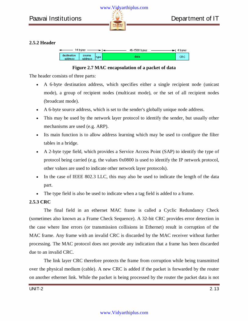
Figure 2.7 MAC encapsulation of a packet of data
The header consists of three parts:
A 6-byte destination address, which specifies either a single recipient node (unicast
mode), a group of recipient nodes (multicast mode), or the set of all recipient nodes
(broadcast mode).
A 6-byte source address, which is set to the sender's globally unique node address.
This may be used by the network layer protocol to identify the sender, but usually other
mechanisms are used (e.g. ARP).
Its main function is to allow address learning which may be used to configure the filter
tables in a bridge.
A 2-byte type field, which provides a Service Access Point (SAP) to identify the type of
protocol being carried (e.g. the values 0x0800 is used to identify the IP network protocol,
other values are used to indicate other network layer protocols).
In the case of IEEE 802.3 LLC, this may also be used to indicate the length of the data
part.
The type field is also be used to indicate when a tag field is added to a frame.
2.5.3 CRC
The final field in an ethernet MAC frame is called a Cyclic Redundancy Check
(sometimes also known as a Frame Check Sequence). A 32-bit CRC provides error detection in
the case where line errors (or transmission collisions in Ethernet) result in corruption of the
MAC frame. Any frame with an invalid CRC is discarded by the MAC receiver without further
processing. The MAC protocol does not provide any indication that a frame has been discarded
due to an invalid CRC.
The link layer CRC therefore protects the frame from corruption while being transmitted
over the physical medium (cable). A new CRC is added if the packet is forwarded by the router
on another ethernet link. While the packet is being processed by the router the packet data is not
www.Vidyarthiplus.com
www.Vidyarthiplus.com
Paavai Institutions Department of IT
UNIT-2 2. 14
protected by the CRC. Router processing errors must be detected by network or transport-layer
checksums.
2.5.4 Inter Frame Gap
After transmission of each frame, a transmitter must wait for a period of 9.6
microseconds (at 10 Mbps) to allow the signal to propagate through the receiver electronics at
the destination. This period of time is known as the Inter-Frame Gap (IFG). While every
transmitter must wait for this time between sending frames, receivers do not necessarily see a
"silent" period of 9.6 microseconds. The way in which repeaters operate is such that they may
reduce the IFG between the frames which they regenerate.
2.5.5 Byte Order
It is important to realize that nearly all serial communications systems transmit the least
significant bit of each byte first at the physical layer. Ethernet supports broadcast, unicast, and
multicast addresses. The appearance of a multicast address on the cable (in this case an IP
multicast address, with group set to the bit pattern 0xxx xxxx xxxx xxxx xxxx xxxx) is therefore
as shown below (bits transmitted from left to right):
0 23 IP Multicast Address Group 47
| | <--------------------------->|
1000 0000 0000 0000 0111 1010 xxxx xxx0 xxxx xxxx xxxx xxxx
| |
Multicast Bit 0 = Internet Multicast 1 = Assigned for other uses
When the same frame is stored in the memory of a computer, the bits are ordered such
that the least significant bit of each byte is stored in the right most position (the bits are
transmitted right-to-left within bytes, bytes transmitted left-to-right):
0 23 47
| | |
0000 0001 0000 0000 0101 1110 0xxx xxxx xxxx xxxx xxxx xxxx
| <--------------------------->
Multicast Bit IP Multicast Address Group
www.Vidyarthiplus.com
www.Vidyarthiplus.com
Paavai Institutions Department of IT
UNIT-2 2. 15
2.5.6 CSMA /CD
The Carrier Sense Multiple Access (CSMA) with Collision Detection (CD) protocol is
used to control access to the shared ethernet medium. A switched network (e.g. Fast Ethernet)
may use a full duplex mode giving access to the full link speed when used between directly
connected two NICs, Switch to NIC cables, or Switch to Switch cables.
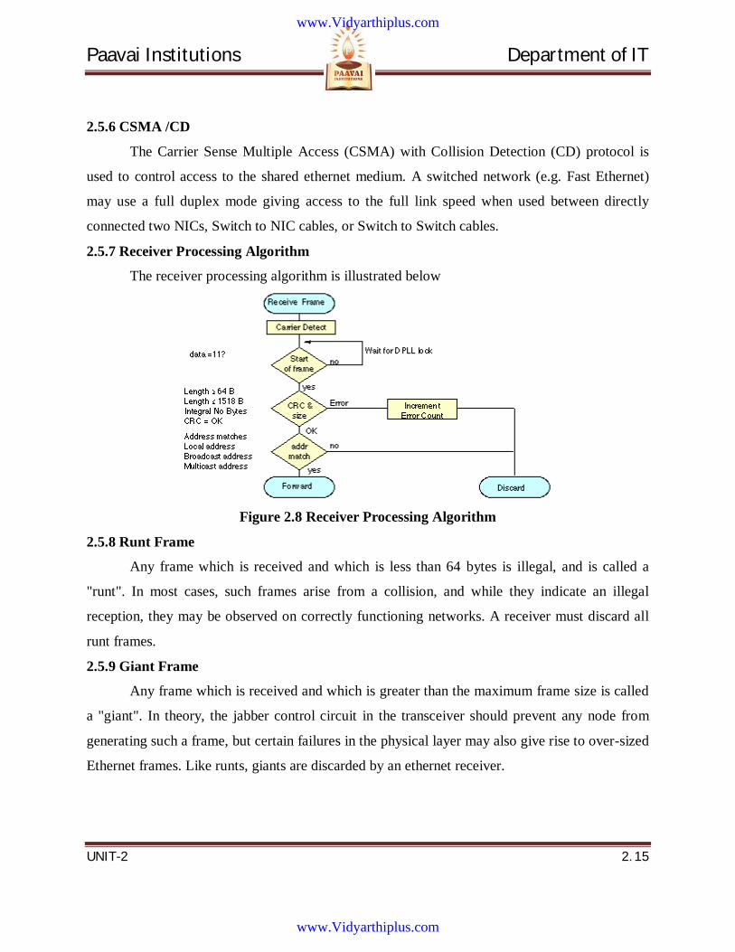
2.5.7 Receiver Processing Algorithm
The receiver processing algorithm is illustrated below
Figure 2.8 Receiver Processing Algorithm
2.5.8 Runt Frame
Any frame which is received and which is less than 64 bytes is illegal, and is called a
"runt". In most cases, such frames arise from a collision, and while they indicate an illegal
reception, they may be observed on correctly functioning networks. A receiver must discard all
runt frames.
2.5.9 Giant Frame
Any frame which is received and which is greater than the maximum frame size is called
a "giant". In theory, the jabber control circuit in the transceiver should prevent any node from
generating such a frame, but certain failures in the physical layer may also give rise to over-sized
Ethernet frames. Like runts, giants are discarded by an ethernet receiver.
www.Vidyarthiplus.com
www.Vidyarthiplus.com
Paavai Institutions Department of IT
UNIT-2 2. 16
2.5.10 Jumbo Frame
Some modern Gigabit Ethernet NICs support frames that are larger than the traditional
1500 bytes specified by the IEEE. This new mode requires support by both ends of the link to
support Jumbo Frames. Path MTU Discovery is required for a router to utilize this feature, since
there is no other way for a router to determine that all systems on the end-to-end path will
support these larger sized frames.
2.5.11 Misaligned Frame
Any frame which does not contain an integral number of received bytes (bytes) is also
illegal. A receiver has no way of knowing which bits are legal, and how to compute the CRC-32
of the frame. Such frames are therefore also discarded by the ethernet receiver.
2.5.12 Other Issues
The ethernet standard dictates a minimum size of frame, which requires at least 46 bytes
of data to be present in every MAC frame. If the network layer wishes to send less than 46 bytes
of data the MAC protocol adds sufficient number of zero bytes (0x00, is also known as null
padding characters) to satisfy this requirement. The maximum size of data which may be carried
in a MAC frame using Ethernet is 1500 bytes (this is known as the MTU in IP).
2.6 Introduction to CDMA based systems 2.6.1 Spread Spectrum in CDMA systems
CDMA is a form of Direct Sequence Spread Spectrum communications. In general,
Spread Spectrum communications is distinguished by three key elements:
1. The signal occupies a bandwidth much greater than that which is necessary to send the
information.
2. This results in many benefits, such as immunity to interference and jamming and multi-
user access, which we’ll discuss later on.
3. The bandwidth is spread by means of a code which is independent of the data.
4. The independence of the code distinguishes this from standard modulation schemes in
which the data modulation will always spread the spectrum.
5. The receiver synchronizes to the code to recover the data.
www.Vidyarthiplus.com
www.Vidyarthiplus.com
Paavai Institutions Department of IT
UNIT-2 2. 17
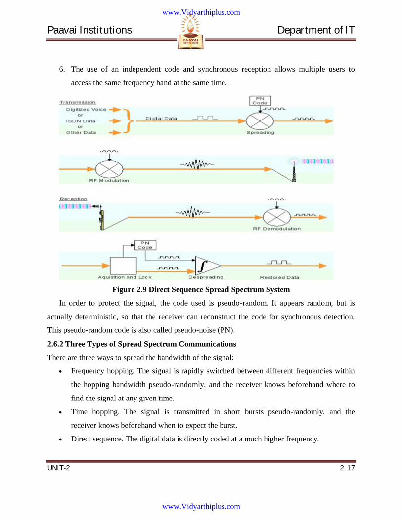
6. The use of an independent code and synchronous reception allows multiple users to
access the same frequency band at the same time.
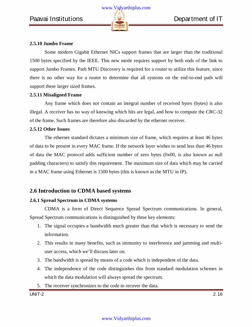
Figure 2.9 Direct Sequence Spread Spectrum System
In order to protect the signal, the code used is pseudo-random. It appears random, but is
actually deterministic, so that the receiver can reconstruct the code for synchronous detection.
This pseudo-random code is also called pseudo-noise (PN).
2.6.2 Three Types of Spread Spectrum Communications
There are three ways to spread the bandwidth of the signal:
Frequency hopping. The signal is rapidly switched between different frequencies within
the hopping bandwidth pseudo-randomly, and the receiver knows beforehand where to
find the signal at any given time.
Time hopping. The signal is transmitted in short bursts pseudo-randomly, and the
receiver knows beforehand when to expect the burst.
Direct sequence. The digital data is directly coded at a much higher frequency.
www.Vidyarthiplus.com
www.Vidyarthiplus.com
Paavai Institutions Department of IT
UNIT-2 2. 18
The code is generated pseudo-randomly, the receiver knows how to generate the same
code, and correlates the received signal with that code to extract the data.
2.6.3 Direct Sequence Spread Spectrum
CDMA is a Direct Sequence Spread Spectrum system. The CDMA system works directly
on 64 kb/sec digital signals. These signals can be digitized voice, ISDN channels, modem data,
etc. Figure 2.9 shows a simplified Direct Sequence Spread Spectrum system. For clarity, the
figure shows one channel operating in one direction only.
Signal transmission consists of the following steps:
1. A pseudo-random code is generated, different for each channel and each successive
connection.
2. The Information data modulates the pseudo-random code (the Information data is
“spread”).
3. The resulting signal modulates a carrier.
4. The modulated carrier is amplified and broadcast.
Signal reception consists of the following steps:
The carrier is received and amplified.
The received signal is mixed with a local carrier to recover the spread digital signal.
A pseudo-random code is generated, matching the anticipated signal.
The receiver acquires the received code and phase locks its own code to it.
The received signal is correlated with the generated code, extracting the information data.
2.7 Coding Methods in CDMA The following sections describe how a system might implement the steps illustrated in
figure 2.9
2.7.1 Input data
CDMA works on information data from several possible sources, such as digitized voice
or ISDN channels. Data rates can vary, here are some examples:
www.Vidyarthiplus.com
www.Vidyarthiplus.com
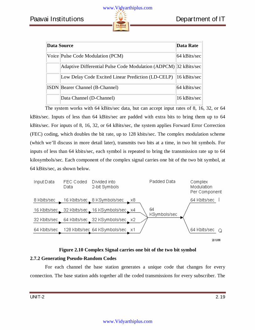
Paavai Institutions Department of IT
UNIT-2 2. 19
Data Source Data Rate
Voice Pulse Code Modulation (PCM) 64 kBits/sec
Adaptive Differential Pulse Code Modulation (ADPCM) 32 kBits/sec
Low Delay Code Excited Linear Prediction (LD-CELP) 16 kBits/sec
ISDN Bearer Channel (B-Channel) 64 kBits/sec
Data Channel (D-Channel) 16 kBits/sec
The system works with 64 kBits/sec data, but can accept input rates of 8, 16, 32, or 64
kBits/sec. Inputs of less than 64 kBits/sec are padded with extra bits to bring them up to 64
kBits/sec. For inputs of 8, 16, 32, or 64 kBits/sec, the system applies Forward Error Correction
(FEC) coding, which doubles the bit rate, up to 128 kbits/sec. The complex modulation scheme
(which we’ll discuss in more detail later), transmits two bits at a time, in two bit symbols. For
inputs of less than 64 kbits/sec, each symbol is repeated to bring the transmission rate up to 64
kilosymbols/sec. Each component of the complex signal carries one bit of the two bit symbol, at
64 kBits/sec, as shown below.
Figure 2.10 Complex Signal carries one bit of the two bit symbol
2.7.2 Generating Pseudo-Random Codes
For each channel the base station generates a unique code that changes for every
connection. The base station adds together all the coded transmissions for every subscriber. The
www.Vidyarthiplus.com
www.Vidyarthiplus.com
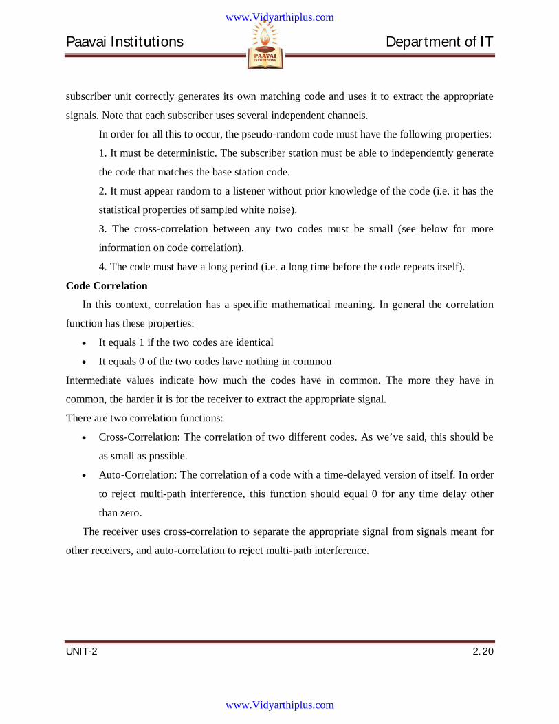
Paavai Institutions Department of IT
UNIT-2 2. 20
subscriber unit correctly generates its own matching code and uses it to extract the appropriate
signals. Note that each subscriber uses several independent channels.
In order for all this to occur, the pseudo-random code must have the following properties:
1. It must be deterministic. The subscriber station must be able to independently generate
the code that matches the base station code.
2. It must appear random to a listener without prior knowledge of the code (i.e. it has the
statistical properties of sampled white noise).
3. The cross-correlation between any two codes must be small (see below for more
information on code correlation).
4. The code must have a long period (i.e. a long time before the code repeats itself).
Code Correlation
In this context, correlation has a specific mathematical meaning. In general the correlation
function has these properties:
It equals 1 if the two codes are identical
It equals 0 of the two codes have nothing in common
Intermediate values indicate how much the codes have in common. The more they have in
common, the harder it is for the receiver to extract the appropriate signal.
There are two correlation functions:
Cross-Correlation: The correlation of two different codes. As we’ve said, this should be
as small as possible.
Auto-Correlation: The correlation of a code with a time-delayed version of itself. In order
to reject multi-path interference, this function should equal 0 for any time delay other
than zero.
The receiver uses cross-correlation to separate the appropriate signal from signals meant for
other receivers, and auto-correlation to reject multi-path interference.
www.Vidyarthiplus.com
www.Vidyarthiplus.com
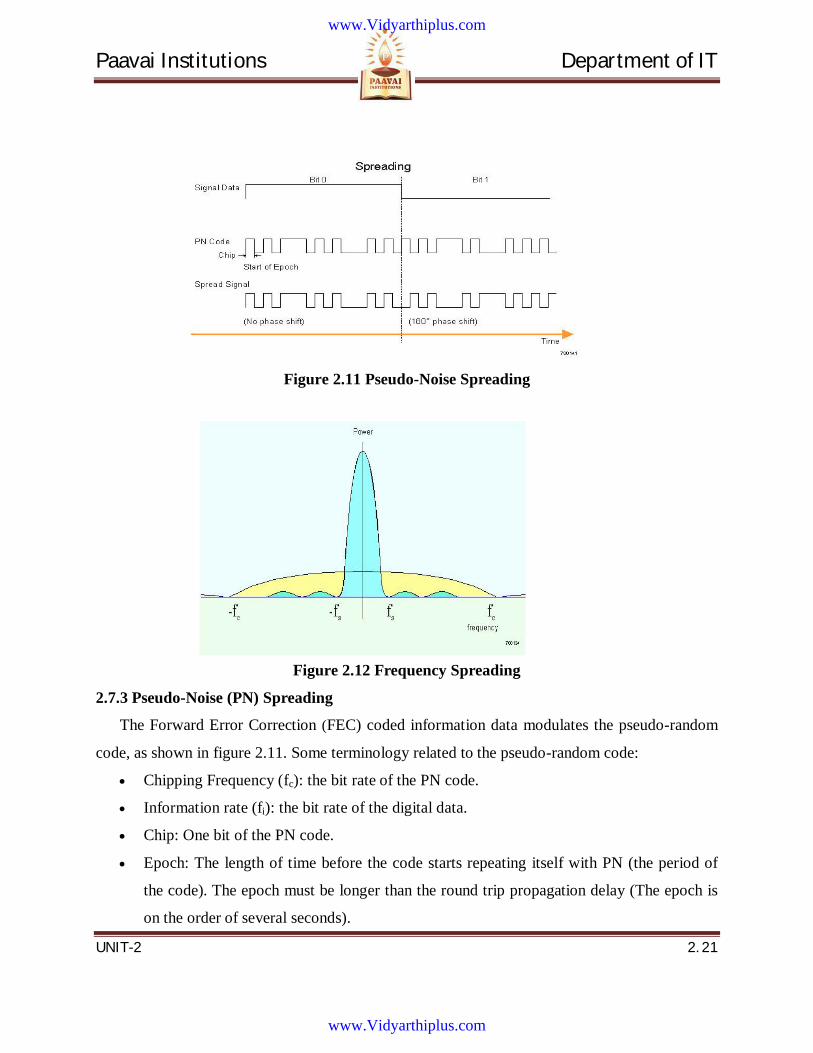
Paavai Institutions Department of IT
UNIT-2 2. 21
Figure 2.11 Pseudo-Noise Spreading
Figure 2.12 Frequency Spreading
2.7.3 Pseudo-Noise (PN) Spreading
The Forward Error Correction (FEC) coded information data modulates the pseudo-random
code, as shown in figure 2.11. Some terminology related to the pseudo-random code:
Chipping Frequency (fc): the bit rate of the PN code.
Information rate (fi): the bit rate of the digital data.
Chip: One bit of the PN code.
Epoch: The length of time before the code starts repeating itself with PN (the period of
the code). The epoch must be longer than the round trip propagation delay (The epoch is
on the order of several seconds).
www.Vidyarthiplus.com
www.Vidyarthiplus.com

Paavai Institutions Department of IT
UNIT-2 2. 22
Figure 2.12 shows the process of frequency spreading. In general, the bandwidth of a digital
signal is twice its bit rate. The bandwidths of the information data (fi) and the PN code are shown
together. The bandwidth is the combination of the two for fc>fi and fc<fi and it can be
approximated by the bandwidth of the PN code.
Processing Gain
An important concept relating to the bandwidth is the processing gain (Gp). This is a
theoretical system gain that reflects the relative advantage that frequency spreading provides.
The processing gain is equal to the ratio of the chipping frequency to the data frequency:
i
cp f
fG
There are two major benefits from high processing gain:
Interference rejection: the ability of the system to reject interference is directly
proportional to Gp.
System capacity: the capacity of the system is directly proportional to Gp.
So higher the PN code bit rate (the wider the CDMA bandwidth), better the system
performance.
Figure 2.13 Complex Modulator
www.Vidyarthiplus.com
www.Vidyarthiplus.com
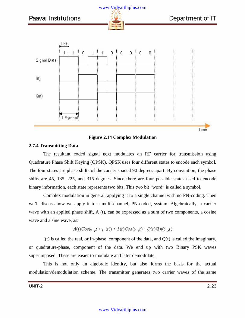
Paavai Institutions Department of IT
UNIT-2 2. 23
Figure 2.14 Complex Modulation
2.7.4 Transmitting Data
The resultant coded signal next modulates an RF carrier for transmission using
Quadrature Phase Shift Keying (QPSK). QPSK uses four different states to encode each symbol.
The four states are phase shifts of the carrier spaced 90 degrees apart. By convention, the phase
shifts are 45, 135, 225, and 315 degrees. Since there are four possible states used to encode
binary information, each state represents two bits. This two bit “word” is called a symbol.
Complex modulation in general, applying it to a single channel with no PN-coding. Then
we’ll discuss how we apply it to a multi-channel, PN-coded, system. Algebraically, a carrier
wave with an applied phase shift, A (t), can be expressed as a sum of two components, a cosine
wave and a sine wave, as:
I(t) is called the real, or In-phase, component of the data, and Q(t) is called the imaginary,
or quadrature-phase, component of the data. We end up with two Binary PSK waves
superimposed. These are easier to modulate and later demodulate.
This is not only an algebraic identity, but also forms the basis for the actual
modulation/demodulation scheme. The transmitter generates two carrier waves of the same
www.Vidyarthiplus.com
www.Vidyarthiplus.com
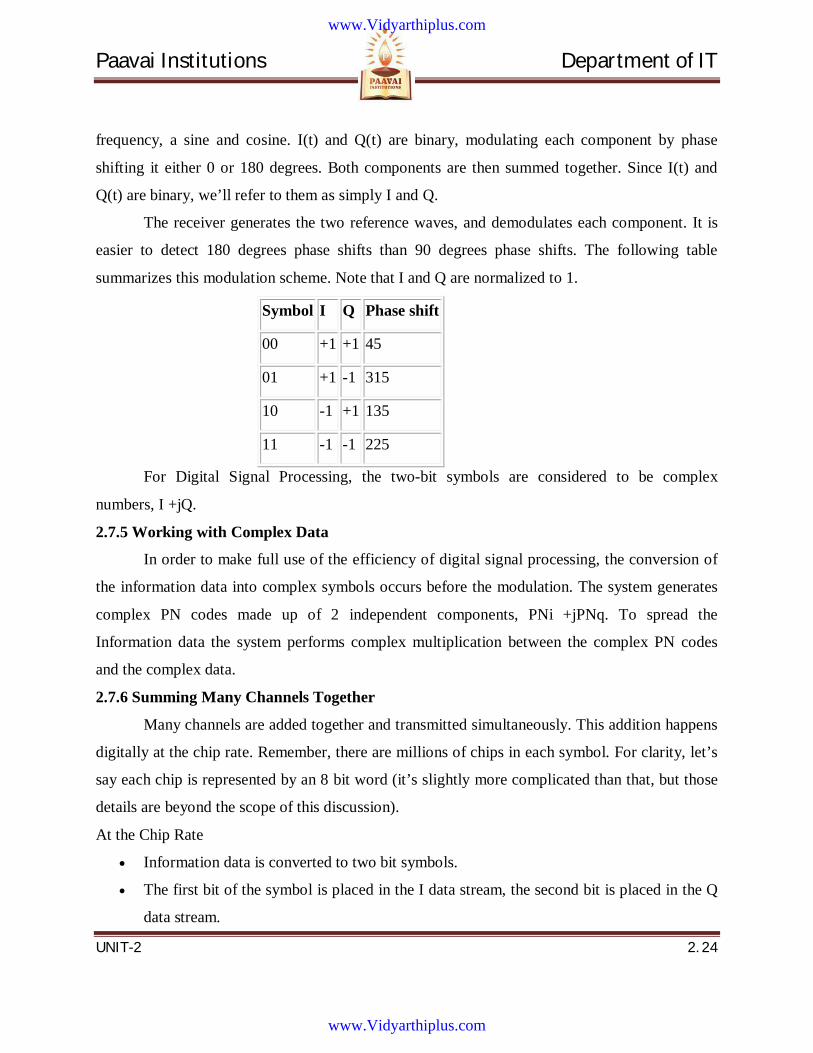
Paavai Institutions Department of IT
UNIT-2 2. 24
frequency, a sine and cosine. I(t) and Q(t) are binary, modulating each component by phase
shifting it either 0 or 180 degrees. Both components are then summed together. Since I(t) and
Q(t) are binary, we’ll refer to them as simply I and Q.
The receiver generates the two reference waves, and demodulates each component. It is
easier to detect 180 degrees phase shifts than 90 degrees phase shifts. The following table
summarizes this modulation scheme. Note that I and Q are normalized to 1.
Symbol I Q Phase shift
00 +1 +1 45
01 +1 -1 315
10 -1 +1 135
11 -1 -1 225
For Digital Signal Processing, the two-bit symbols are considered to be complex
numbers, I +jQ.
2.7.5 Working with Complex Data
In order to make full use of the efficiency of digital signal processing, the conversion of
the information data into complex symbols occurs before the modulation. The system generates
complex PN codes made up of 2 independent components, PNi +jPNq. To spread the
Information data the system performs complex multiplication between the complex PN codes
and the complex data.
2.7.6 Summing Many Channels Together
Many channels are added together and transmitted simultaneously. This addition happens
digitally at the chip rate. Remember, there are millions of chips in each symbol. For clarity, let’s
say each chip is represented by an 8 bit word (it’s slightly more complicated than that, but those
details are beyond the scope of this discussion).
At the Chip Rate
Information data is converted to two bit symbols.
The first bit of the symbol is placed in the I data stream, the second bit is placed in the Q
data stream.
www.Vidyarthiplus.com
www.Vidyarthiplus.com
Paavai Institutions Department of IT
UNIT-2 2. 25
The complex PN code is generated. The complex PN code has two independently
generated components, an I component and a Q component.
The complex Information data and complex PN code are multiplied together.
For each component (I or Q):
Each chip is represented by an 8 bit word. However, since one chip is either a one or a
zero, the 8 bit word equals either 1 or -1.
When many channels are added together, the 8-bit word, as the sum of all the chips, can
take on values from between -128 to +128.
The 8-bit word then goes through a Digital to Analog Converter, resulting in an analog
level proportional to the value of the 8-bit word.
This value then modulates the amplitude of the carrier (the I component modulates the
Cosine, the Q component modulates the Sine)
The modulated carriers are added together.
2.7.7 Receiving Data
The receiver performs the following steps to extract the Information:
Demodulation
Code acquisition and lock
Correlation of code with signal
Decoding of Information data
Demodulation
The receiver generates two reference waves, a cosine wave and a sine wave. Separately
mixing each with the received carrier, the receiver extracts I(t) and Q(t). Analog to Digital
converters restore the 8-bit words representing the I and Q chips.
Code Acquisition and Lock
The receiver, as described earlier, generates its own complex PN code that matches the
code generated by the transmitter. However, the local code must be phase-locked to the encoded
data. The RCS and FSU each have different ways of acquiring and locking onto the other’s
transmitted code. Each method will be covered in more detail in later sections.
www.Vidyarthiplus.com
www.Vidyarthiplus.com
Paavai Institutions Department of IT
UNIT-2 2. 26
Correlation and Data Despreading
Once the PN code is phase-locked to the pilot, the received signal is sent to a correlator
that multiplies it with the complex PN code, extracting the I and Q data meant for that receiver.
The receiver reconstructs the information data from the I and Q data.
Automatic Power Control
The RCS gets bombarded by signals from many FSUs. Some of these FSUs are close and
their signals are much stronger than FSUs farther away. This results in the Near/Far problem
inherent in CDMA communications. System Capacity is also dependant on signal power. For
these reasons, both the RCS and FSU measure the received power and send signals to control the
others transmit power.
Near/Far Problem
The near-far problem is a condition in which a receiver captures a strong signal and
thereby makes it impossible for the receiver to detect a weaker signal.
Interference Rejection
CDMA technology is inherently resistant to interference and jamming. A common
problem with urban communications is multi-path interference. Multi-path interference is caused
by the broadcast signal traveling over different paths to reach the receiver. The receiver then has
to recover the signal combined with echoes of varying amplitude and phase. This results in two
types of interference:
Inter-chip interference: The reflected signals are delayed long enough that successive bits
(or chips, in this case) in the demodulated signals overlap, creating uncertainty in the
data.
Selective fading: The reflected signals are delayed long enough that they are randomly
out of phase, and add destructively to the desired signal, causing it to fade.
www.Vidyarthiplus.com
www.Vidyarthiplus.com
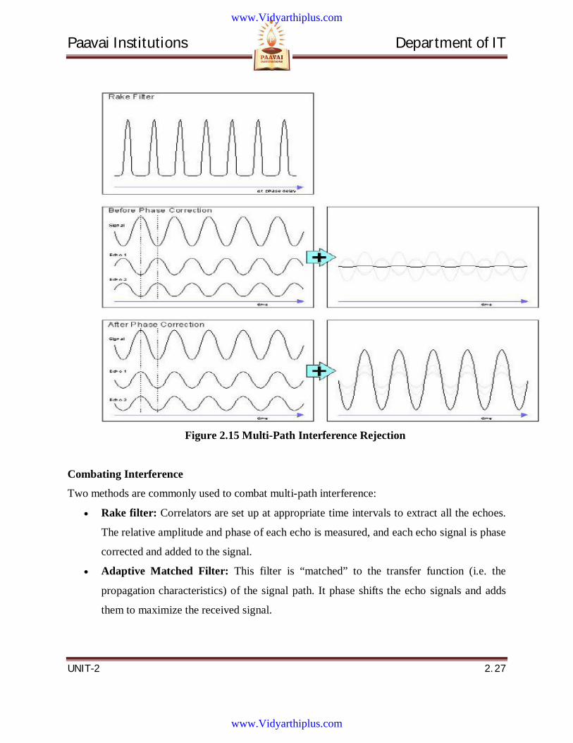
Paavai Institutions Department of IT
UNIT-2 2. 27
Figure 2.15 Multi-Path Interference Rejection
Combating Interference
Two methods are commonly used to combat multi-path interference:
Rake filter: Correlators are set up at appropriate time intervals to extract all the echoes.
The relative amplitude and phase of each echo is measured, and each echo signal is phase
corrected and added to the signal.
Adaptive Matched Filter: This filter is “matched” to the transfer function (i.e. the
propagation characteristics) of the signal path. It phase shifts the echo signals and adds
them to maximize the received signal.
www.Vidyarthiplus.com
www.Vidyarthiplus.com
Paavai Institutions Department of IT
UNIT-2 2. 28
System Operation
The following sections describe a hypothetical implementation of CDMA technology. A
connection can be one of many types of data, but for simplicity we will refer to any connection
as a “call”.
These sections cover the following system states:
System Idle: System operation when there is no call in progress.
Call Setup: The steps to setup a connection.
Call Processing: The processing and transmission of the digital data once a connection is
established.
Call Teardown: The steps taken once a call is finished to free system resources.
But first, in order to understand system operation, you must understand the Pilot codes and
communication channels the system uses.
Pilot Codes
At each phase of operation, the system broadcasts pilot signals. These pilot signals are the
unmodulated PN codes associated with each channel, used to synchronize and track the locally
generated PN codes for despreading. The system uses the following pilot signals.
Global Pilot: Broadcast by the RCS. All FSUs use the Global Pilot for all received
channels.
Short Access Pilot: Broadcast by FSU. Monitored by the RCS for an incoming access
attempt by an FSU. Alerts the RCS that an FSU is requesting access.
Long Access Pilot: Broadcast by the FSU. Allows the RCS to synchronize to the FSU to
setup a call.
Assigned Pilot: Broadcast by FSU. Unmodulated PN code of the assigned channel.
Allows RCS to synchronize to and track the PN codes of the FSU assigned channels for
despreading.
Communication Channels
In order to understand system operation, we need to introduce the system communication
channels. The system has the following channel groups:
The Broadcast Channel group: Channels continuously broadcasted by the RCS.
www.Vidyarthiplus.com
www.Vidyarthiplus.com
Paavai Institutions Department of IT
UNIT-2 2. 29
Call Setup Channel group: Channels used to setup a call. There are four sets of these
channels; up to 4 FSUs can request access at one time.
Assigned Channel group: Channels used for the call.
Each logical channel in each group is realized by assigning a unique PN code to it.
Table 2.1 Channel group and Name description
Channel
Group
Channel
Name
Direction Number of
Channels
Description
Broadcast Global Pilot F One An unmodulated PN code that the FSU can
synchronize to.
Fast
Broadcast
Channel
F One A single message indicating which services
and access channels are available. This
information may change rapidly.
Slow
Broadcast
Channel
F One Paging messages and other system
information that does not need to be
updated rapidly.
Call Setup Short Pilot R Four Alerts the RCS that an FSU is requesting
access.
Long Pilot Four Allows the RCS to synchronize to the FSU
to setup a call.
Access
Channel
R Four Used by the FSUs to access an RCS and
get assigned channels.
Control
Channel
F Four Used by the RCS to reply to access
attempts from FSUs.
Control
Channel APC
F Four Controls FSU power during initial access.
Assigned Assigned R One per FSU An unmodulated PN code that the RCS can
www.Vidyarthiplus.com
www.Vidyarthiplus.com
Paavai Institutions Department of IT
UNIT-2 2. 30
Pilot synchronize to.
APC Channel F One per FSU Controls FSU power during call.
R Controls RCS power of assigned FSU
channels.
Traffic
Channels
F Up to 3 per
FSU
Signal data from RCS to FSU.
R Signal data from FSU to RCS.
Order wire F One per FSU Control signals: CDMA and Telco
messages.
R
Note on Direction: F - Forward - From RCS to FSU
R - Reverse - From FSU to RCS
Pilot Ramp Up
When the FSU transmits its Short and Long Access Pilots, it ramps the power up to
determine what power level it should transmit. When the RCS detects the Short Access Pilot, it
acknowledges over the Fast Broadcast Channel. The FSU then knows that it is being received,
and switches to the Long Access Pilot code. The Long Access Pilot code ramps up more slowly,
until the RCS locks and starts transmitting Automatic Power Control signals.
System Idle
On startup, the RCS places one of its modems in broadcast mode, in which state it broadcasts
the following Global Channels continuously:
Global Pilot
Slow Broadcast Channel
Fast Broadcast Channel
www.Vidyarthiplus.com
www.Vidyarthiplus.com
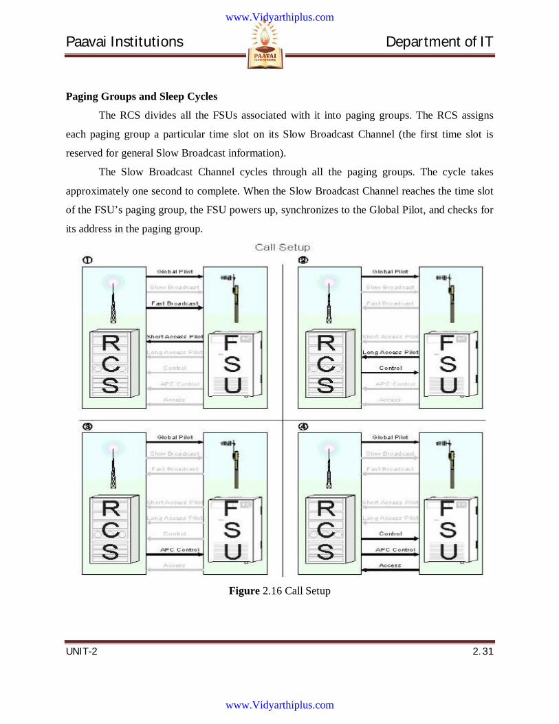
Paavai Institutions Department of IT
UNIT-2 2. 31
Paging Groups and Sleep Cycles
The RCS divides all the FSUs associated with it into paging groups. The RCS assigns
each paging group a particular time slot on its Slow Broadcast Channel (the first time slot is
reserved for general Slow Broadcast information).
The Slow Broadcast Channel cycles through all the paging groups. The cycle takes
approximately one second to complete. When the Slow Broadcast Channel reaches the time slot
of the FSU’s paging group, the FSU powers up, synchronizes to the Global Pilot, and checks for
its address in the paging group.
Figure 2.16 Call Setup
www.Vidyarthiplus.com
www.Vidyarthiplus.com
Paavai Institutions Department of IT
UNIT-2 2. 32
Call Setup
Two events can initiate a call:
The FSU receives a page from the RCS. This is called a terminating call.
The FSU generates an off-hook signal in response to subscriber equipment.
The FSU locks on to the Global Pilot. This is called an originating call.
Once either of these events occurs, call setup proceeds as follows:
1. FSU requests access.
FSU transmits Short Access Pilot Code.
RCS detects transmission and acknowledges. Flags Call Setup Channel as busy.
FSU transmits Long Access Pilot Code.
RCS synchronizes to the FSU and confirms sync over Control Channel.
RCS measures received power and starts transmitting APC signal on APC Control
Channel.
RCS and FSU exchange messages on Access and Control Channels.
Type of service and types of traffic channels are specified.
2. RCS assigns channel group to FSU.
RCS designates assigned code on Control Channel
FSU generates complex PN codes for all channels in its assigned group.
Both FSU and RCS synchronously switch to the assigned channel groups.
The call is connected.
The RCS flags the Call Setup Channel as available, and assigns it to the next available
modem.
Note that the RCS now tracks the Assigned Pilot; the FSU continues to track the Global Pilot.
Call Processing
Call processing puts together everything we’ve covered so far. There are slight
differences in the way the RCS and FSU process calls, so we will cover both the Forward link
(RCS to FSU) and Reverse link (FSU to RCS). Note that the system uses Frequency Division
Duplexing for the Forward and Reverse links: they transmit over different frequencies.
In the forward direction, the RCS:
www.Vidyarthiplus.com
www.Vidyarthiplus.com
Paavai Institutions Department of IT
UNIT-2 2. 33
1. Generates CDMA data signal for each traffic channel:
FEC codes the Information data, and converts the data to two-bit symbols.
Converts the symbols to I and Q data, and pads each data stream to 64 kbits/sec.
Generates the Complex PN code for each channel.
Multiplies the Complex Information data and the Complex PN code together.
Reads APC data from FSU, digitally scales channels accordingly.
2. Generates other signal channels:
Calculates APC signal
Converts it to I data only
Multiplies it with its own Complex PN code
3. Adds all signals together:
Traffic channels
APC channel
Order Wire channel
Global Pilot
4. Adds together the signals for all currently active FSUs.
5. Modulates and transmits carriers
I and Q data modulate Cosine and Sine carriers.
Carriers are combined, amplified, and broadcast.
The FSU:
1. Extracts the I and Q data:
Receives and amplifies the modulated carriers.
Demodulates the signal and extracts the I and Q data.
2. Filters the I and Q data:
Extracts multi-path information from the Pilot Rake filter and supplies it to the Adaptive
Matched Filter.
Removes multi-path interference from I and Q data using the Adaptive Matched Filter.
Performs Automatic Gain Control on received signal
3. Extracts the CDMA data signal for each traffic channel:
www.Vidyarthiplus.com
www.Vidyarthiplus.com
Paavai Institutions Department of IT
UNIT-2 2. 34
Generates the Complex PN code for each channel.
Multiplies the Complex signal and the Complex PN code together.
Converts the I and Q data to symbols.
Decodes the symbols for error correction.
Extracts the signal data.
In the reverse direction, the FSU:
1. Generates CDMA data signal for each traffic channel:
FEC codes the Information data, and converts the data to two-bit symbols.
Converts the symbols to I and Q data, and pads each data stream to 64 kbits/sec.
Generates the Complex PN code for each channel.
Multiplies the Complex signal and the Complex PN code together.
Reads APC data from FSU, digitally scales channels accordingly.
2. Generates other signal channels:
Calculates APC signal
Converts it to I data only
Multiplies it with its own Complex PN code
3. Adds all signals together:
Traffic channels
APC channel
Order Wire channel
Global Pilot
4. Passes the signal through a pulse shaping digital filter.
5. Modulates and transmits carriers
I and Q data modulate Cosine and Sine carriers.
Carriers are combined, amplified, and broadcast.
The RCS:
1. Extracts the I and Q data:
Receives and amplifies the modulated carriers and demodulates the signal and extracts
the I and Q data.
www.Vidyarthiplus.com
www.Vidyarthiplus.com
Paavai Institutions Department of IT
UNIT-2 2. 35
2. Filters the I and Q data:
Extracts multi-path information from the Pilot Rake filter and supplies it to the Adaptive
Matched Filter and removes multi-path interference from I and Q data using the Adaptive
Matched Filter. It Performs Automatic Gain Control on the received signal
3. Extracts the CDMA data signal for each traffic channel, for each subscriber connection:
Generates the Complex PN code for each channel.
Multiplies the Complex signal and the Complex PN code together.
Converts the I and Q data to symbols and decodes the symbols for error correction.
Extracts the Information data.
Call Teardown
An on-hook signal causes the RCS to release the resources, and the FSU returns to its idle
state.
www.Vidyarthiplus.com
www.Vidyarthiplus.com
Paavai Institutions Department of IT
UNIT-2 2. 36
2.8 QUESTION BANK
PART-A
1. What is meant by cellular system?
2. What is meant by Frequency management?
3. What is the interference in cellular system?
4. What is Interference in Cellular Systems?
5. What is Channel Assignment?
6. What is Location management in cellular networks?
7. Define Medium Access Control.
8. Define CDMA based systems.
9. What is Spread Spectrum in CDMA systems?
10. Define Coding Methods.
11. What are the basic groups of logical channels?
12. What are the categories of Mobile services?
13. What are the basic groups of logical channels?
14. What are the disadvantages of cellular systems?
15. What are subsystems in GSM system?
16. What are the control channel groups in GSM?
17. What are the four types of handover available in GSM?
18. What are types of Handover?
19. What are the services provided by supplementary services?
20. What is authentication centre (AuC)?
www.Vidyarthiplus.com
www.Vidyarthiplus.com
Paavai Institutions Department of IT
UNIT-2 2. 37
PART-B (16 Marks)
1. Explain with diagram the Hidden terminal and exposed terminal problem in CSMA.
2. Explain with diagram the Near-Far terminal problem in CSMA.
3. Explain Location Management in cellular network?
4. Explain Channel Assignment in cellular network?
5. Explain in detail about Coding Methods
6. Explain in detail about Spectrum in CDMA systems.
7. Explain the different types of transport modes and the channel used to carry packets in
Digital Audio Broadcasting.
8. Explain in detail about Digital Audio Broadcasting.
9. Explain in detail about Digital Video Broadcasting.
10. What are different interleaving and repetition schemes applied by DAB to objects and
segments?
www.Vidyarthiplus.com
www.Vidyarthiplus.com
Paavai Institutions Department of IT
UNIT-3 3. 1
UNIT 3
MOBILE IP NETWORK LAYER
www.Vidyarthiplus.com
www.Vidyarthiplus.com
Paavai Institutions Department of IT
UNIT-3 3. 2
CONTENTS
3.1 Mobile IP Protocol Overview
3.1.1 Requirements for the evolution of the new mobile IP protocol
3.1.2 Need for upgrading capacity of Routers, and Data-link and Physical layers
3.1.3 Security Needs
3.1.4 Need for Non-Transparency from higher layers
3.1.5 Reestablishment problems due to Non-Transparency from higher layers
3.1.6 Need of Non-Transparency from higher layers
3.1.7 Examples of Non-Transparency from higher layers
3.1.8 Routing table problems
3.1.9 Reestablishment Problems
3.1.10 Working of Mobile IP
3.1.11Use of HAs and FAs
3.1.12 Mobile IP network employing home and foreign agents
3.1.13 Switching Center home agent (HA)
3.1.14 Paging area
3.1.15 Switching centre foreign agent for a foreign network of visiting MNs
3.1.16 Different paging areas interconnected through gateway routers
3.2 Route optimization
3.2.1 CN (MNk) corresponding with visiting MNI
3.2.2 Mobile IP network employing home and foreign agents FAk and FAj
3.3 Mobility support for IPV6
3.3.1 IP micro-mobility support
3.3.2 Cellular IP
3.4 Connectivity with 3G Networks
3.5 Packet Delivery and Handover Management
3.6 Location Management
3.6.1 Handover Management protocols
3.6.2 Location Management Protocols
www.Vidyarthiplus.com
www.Vidyarthiplus.com
Paavai Institutions Department of IT
UNIT-3 3. 3
3.6.3 Agent Discovery
3.6.4 Agent advertisements
3.6.5 Header extension
3.6.6 Co-located COA
3.6.7 Flags
3.6.8 Agent solicitation
3.7 Registration
3.7.1 Function of HA after registration
3.7.2 Registration steps
3.7.3 Registration
3.7.4 Registration Request
3.7.5 8 flag bits
3.7.6 Registration Reply
3.7.7 New database entry fields after registration at the HA
3.8 Tunneling and Encapsulation
3.8.1Tunneling
3.8.2 IP header-in-IP header Method of encapsulation
3.8.3 Format of Encapsulated data
3.8.4 IP header-in-IP header encapsulation Format of Encapsulated data
3.8.5 Redundancy in IP header-in-IP header method
3.8.6 Minimum Encapsulation (ME) method by IP header of an IP Packet
3.8.7 Deficiencies in the IP header-in-IP header and ME methods
3.8.8 Generic Routing Encapsulation (GRE) by IP header of an IP Packet
3.8.9 Tunnel characteristics
3.8.10 GRE by IP header of an IP Packet
3.8.11 GRE (GRE) Header(s)
3.8.12 IP Header and IP Packet data
3.8.13 Source routing
www.Vidyarthiplus.com
www.Vidyarthiplus.com
Paavai Institutions Department of IT
UNIT-3 3. 4
3.9 Route Optimization
3.9.1 Triangular route
3.9.2 Optimization of route for the triangular routing example
3.9.3 Mobility binding Steps in the calling network
3.9.4 Warning sent to HAl of MNl
3.9.5 Smooth handover in Mobile IP protocol method of optimization
3.9.6 Reverse Tunnel
3.9.7 Advantage of reverse tunneling
3.9.8 Time-to-live for forward and reverse tunneling
3.9.9 Reverse tunneling
3.10 Dynamic Host Configuration Protocol
3.11 Question Bank
www.Vidyarthiplus.com
www.Vidyarthiplus.com
Paavai Institutions Department of IT
UNIT-3 3. 5
TECHNICAL TERMS
1. Home Agent (HA) is a host in the home network of the MN, typically a router. It
registers the location of the MN, tunnels IP packets to the COA
2. Mobility Binding: The Mobile Node sends its registration request to the Home Agent.
The HA sets up a mobility binding containing the mobile node’s home IP address and the
current COA.
3. Tunnel establishes a virtual pipe for data packets between a tunnel entry and a tunnel
endpoint. Packets entering a tunnel are forwarded inside the tunnel and leave the tunnel
unchanged.
4. Encapsulation is the mechanism of taking a packet consisting of packet header and data
putting it into the data part of a new packet.
5. De capsulation is the reverse operation, taking a packet out of the data part of another
packet
6. Cellular IP provides local handovers without renewed registration by installing a single
cellular IP gateway for each domain, which acts to the outside world as a foreign agent.
7. Routing table is maintained and regularly updated by the router
8. Broadcasting is the Message or packet transmits to all the IP addresses which are set for
listening
9. Mobile Node (MN) is node that moves across networks without changing its IP address
10. Correspondent Node (CN) is a host with which MN is “corresponding” (TCP)
11. Foreign Agent (FA) is a host in the current foreign network of the MN, typically a
router. It forwards tunneled packets to the MN, typically the default router for MN
12. Care-of Address (COA) is a address of the current tunnel end-point for the MN (at FA
or MN). The actual location of the MN from an IP point of view
13. Tunneling is an encapsulating IP packet including a path and an original IP packet.
www.Vidyarthiplus.com
www.Vidyarthiplus.com
Paavai Institutions Department of IT
UNIT-3 3. 6
3. MOBILE IP NETWORK LAYER
3.1 Mobile IP Protocol Overview Defined by the Internet Engineering Task Force (IETF)
Described in the IETF RFC 3344
A protocol developed to allow internetwork mobility for wireless nodes without them
having to change their IP addresses by the Internet Engineering Task Force (IETF)
3.1.1 Requirements for the evolution of the new mobile IP protocol
Need for Enhancing IP Network capacity─ Use of the existing IP protocol by large
number of Mobile nodes (MNs) will lead to a decrease in the network.
3.1.2 Need for upgrading capacity of Routers, and Data-link and Physical layers
IP network protocols support 48-bit MAC addresses
But when the number of MNs is large, then other interfaces and lower level protocols
are required
For mobile nodes to move from one place to another while using the existing IP protocol,
new protocols are required at the data-link and physical layer.
3.1.3 Security Needs
The mobility of the called MN must be hidden from the calling MN
When a new IP address allocates at the new hosting subnet of the existing IP based
infrastructure, the identity of the mobile node is not hidden from another host
The MN exposes and lacks security when using the existing IP protocol.
3.1.4 Need for Non-Transparency from higher layers
The transport layer establishes a connection between a given port at a given IP address
(called socket) with a another port at another IP address
The connection, once established by the transport layers between the sockets, is broken as
soon as the new address is assigned.
3.1.5 Reestablishment problems due to Non-Transparency from higher layers
(a) Reestablishment of the connection takes time which means loss of data during that
interval
www.Vidyarthiplus.com
www.Vidyarthiplus.com
Paavai Institutions Department of IT
UNIT-3 3. 7
(b) Reestablishment process has to share the same network and the given transmission rate.
3.1.6 Need of Non-Transparency from higher layers
Any movement of the MN will be transparent to the TCP and to L7 in case the TCP layer
re-establishes the connection when the IP protocol used by the MN
There is, therefore, a need for non-transparency of the MN to distant ports.
3.1.7 Examples of Non-Transparency from higher layers
Assume a distant router is sending data packets for an IP address, presently assigned to a
mobile terminal using another router
When the terminal moves from one service area to another, the routing tables on the route
need to be updated
Till this is done the packets will not reach their new destination.
3.1.8 Routing table problems
The reconfiguration messages for updating the routing tables have to share the same
network and the given transmission rate.
3.1.9 Reestablishment Problems
Reestablishment of the connection takes time and this means loss of data during that
interval
Any movement on the part of the MN transparent and, thus, not secure from the distant
hosts on the network of distant routers.
3.1.10 Working of Mobile IP
A router has a home agent (HA) for a set of home networked MNs, as well as a foreign
agent (FA) for the visiting MNs
An agent ─ software employed at a router or the host serviced by a router.
An MN can access Internet services using the mobile IP protocol
The MN can change its service router when visiting another location (which is serviced
by a different router)
The HA and the FA play a location management role similar to that of the HLR and the
VLR in a GSM system.
www.Vidyarthiplus.com
www.Vidyarthiplus.com
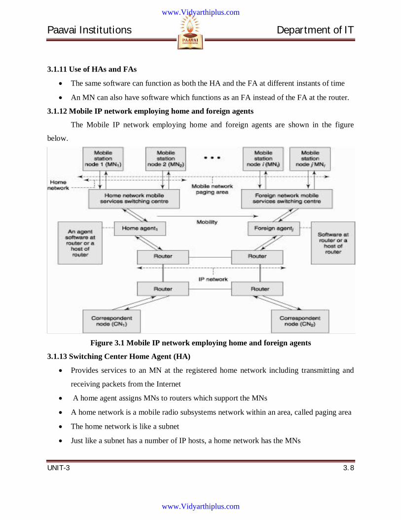
Paavai Institutions Department of IT
UNIT-3 3. 8
3.1.11 Use of HAs and FAs
The same software can function as both the HA and the FA at different instants of time
An MN can also have software which functions as an FA instead of the FA at the router.
3.1.12 Mobile IP network employing home and foreign agents
The Mobile IP network employing home and foreign agents are shown in the figure
below.
Figure 3.1 Mobile IP network employing home and foreign agents
3.1.13 Switching Center Home Agent (HA)
Provides services to an MN at the registered home network including transmitting and
receiving packets from the Internet
A home agent assigns MNs to routers which support the MNs
A home network is a mobile radio subsystems network within an area, called paging area
The home network is like a subnet
Just like a subnet has a number of IP hosts, a home network has the MNs
www.Vidyarthiplus.com
www.Vidyarthiplus.com
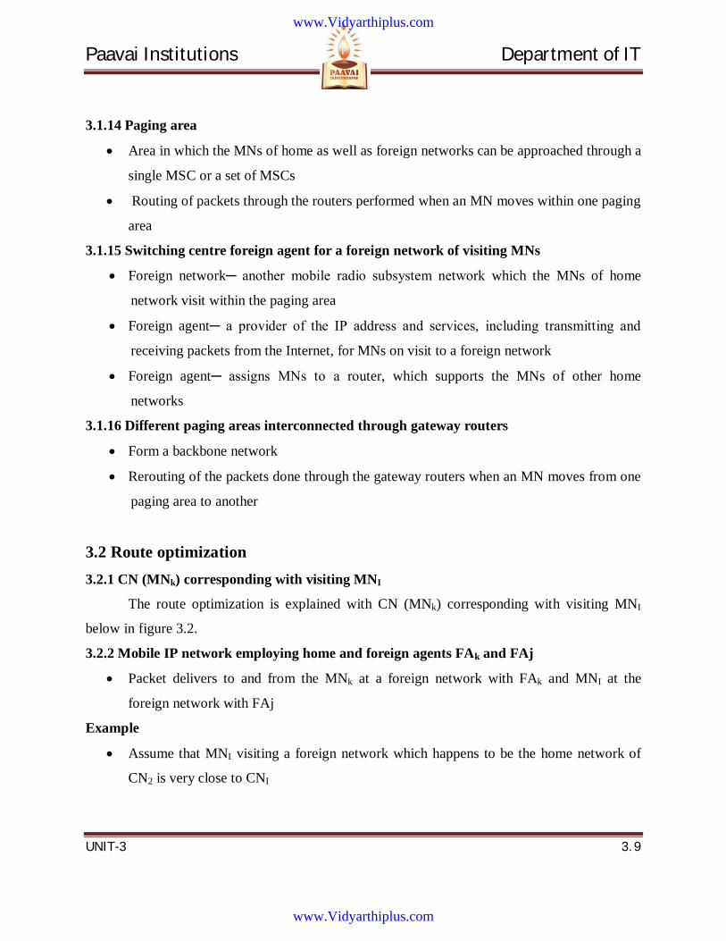
Paavai Institutions Department of IT
UNIT-3 3. 9
3.1.14 Paging area
Area in which the MNs of home as well as foreign networks can be approached through a
single MSC or a set of MSCs
Routing of packets through the routers performed when an MN moves within one paging
area
3.1.15 Switching centre foreign agent for a foreign network of visiting MNs
Foreign network─ another mobile radio subsystem network which the MNs of home
network visit within the paging area
Foreign agent─ a provider of the IP address and services, including transmitting and
receiving packets from the Internet, for MNs on visit to a foreign network
Foreign agent─ assigns MNs to a router, which supports the MNs of other home
networks
3.1.16 Different paging areas interconnected through gateway routers
Form a backbone network
Rerouting of the packets done through the gateway routers when an MN moves from one
paging area to another
3.2 Route optimization 3.2.1 CN (MNk) corresponding with visiting MNI
The route optimization is explained with CN (MNk) corresponding with visiting MNI
below in figure 3.2.
3.2.2 Mobile IP network employing home and foreign agents FAk and FAj
Packet delivers to and from the MNk at a foreign network with FAk and MNI at the
foreign network with FAj
Example
Assume that MNI visiting a foreign network which happens to be the home network of
CN2 is very close to CNI
www.Vidyarthiplus.com
www.Vidyarthiplus.com
Paavai Institutions Department of IT
UNIT-3 3. 10
Figure 3.2 CN (MNk) corresponding with visiting MNI
Triangular route
Triangular route without mobility binding between COAj and CNk
Also possible that FAk and FAj are identical
Optimization of route for the triangular routing example
Optimization of route for the triangular routing can be made in case the MN1 opts to
make its mobility known
www.Vidyarthiplus.com
www.Vidyarthiplus.com
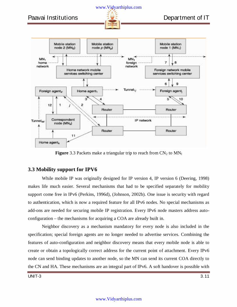
Paavai Institutions Department of IT
UNIT-3 3. 11
Figure 3.3 Packets make a triangular trip to reach from CN2 to MNI
3.3 Mobility support for IPV6 While mobile IP was originally designed for IP version 4, IP version 6 (Deering, 1998)
makes life much easier. Several mechanisms that had to be specified separately for mobility
support come free in IPv6 (Perkins, 1996d), (Johnson, 2002b). One issue is security with regard
to authentication, which is now a required feature for all IPv6 nodes. No special mechanisms as
add-ons are needed for securing mobile IP registration. Every IPv6 node masters address auto-
configuration – the mechanisms for acquiring a COA are already built in.
Neighbor discovery as a mechanism mandatory for every node is also included in the
specification; special foreign agents are no longer needed to advertise services. Combining the
features of auto-configuration and neighbor discovery means that every mobile node is able to
create or obtain a topologically correct address for the current point of attachment. Every IPv6
node can send binding updates to another node, so the MN can send its current COA directly to
the CN and HA. These mechanisms are an integral part of IPv6. A soft handover is possible with
www.Vidyarthiplus.com
www.Vidyarthiplus.com
Paavai Institutions Department of IT
UNIT-3 3. 12
IPv6. The MN sends its new COA to the old router servicing the MN at the old COA, and the old
router encapsulates all incoming packets for the MN and forwards them to the new COA.
Altogether, mobile IP in IPv6 networks requires very few additional mechanisms of a
CN, MN, and HA. The FA is not needed any more. A CN only has to be able to process binding
updates, i.e., to create or to update an entry in the routing cache. The MN itself has to be able to
decapsulate packets, to detect when it needs a new COA, and to determine when to send binding
updates to the HA and CN. A HA must be able to encapsulate packets.
3.3.1 IP micro-mobility support
Mobile IP exhibits several problems regarding the duration of handover and the
scalability of the registration procedure. Assuming a large number of mobile devices changing
networks quite frequently, a high load on the home agents as well as on the networks is
generated by registration and binding update messages. IP micro-mobility protocols can
complement mobile IP by offering fast and almost seamless handover control in limited
geographical areas.
Consider a client arriving with his or her laptop at the customer’s premises. The home
agent only has to know an entry point to the customer’s network, not the details within this
network. The entry point acts as the current location. Changes in the location within the
customer’s network should be handled locally to minimize network traffic and to speed-up local
handover.
The basic underlying idea is the same for all micro-mobility protocols: Keep the frequent
updates generated by local changes of the points of attachment away from the home network and
only inform the home agent about major changes, i.e., changes of a region. In some sense all
micro-mobility protocols establish a hierarchy. However, the debate is still going on if micro-
mobility aspects should really be handled on the IP layer or if layer 2 is the better place for it.
Layer 2 mobility support would comprise, e.g., the inter access point protocol (IAPP) of 802.11
WLANs or the mobility support mechanisms of mobile phone systems.
The following presents three of the most prominent approaches, which should be seen
neither as standards nor as final solutions of the micro-mobility problems. Campbell (2002)
presents a comparison of the three approaches.
www.Vidyarthiplus.com
www.Vidyarthiplus.com
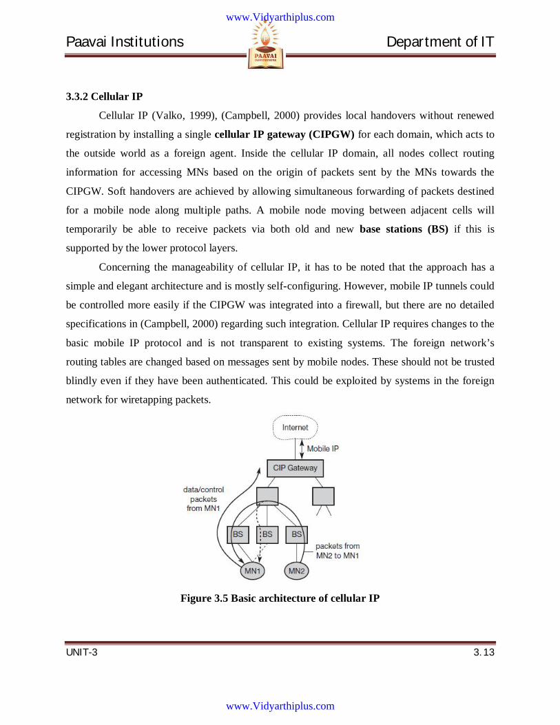
Paavai Institutions Department of IT
UNIT-3 3. 13
3.3.2 Cellular IP
Cellular IP (Valko, 1999), (Campbell, 2000) provides local handovers without renewed
registration by installing a single cellular IP gateway (CIPGW) for each domain, which acts to
the outside world as a foreign agent. Inside the cellular IP domain, all nodes collect routing
information for accessing MNs based on the origin of packets sent by the MNs towards the
CIPGW. Soft handovers are achieved by allowing simultaneous forwarding of packets destined
for a mobile node along multiple paths. A mobile node moving between adjacent cells will
temporarily be able to receive packets via both old and new base stations (BS) if this is
supported by the lower protocol layers.
Concerning the manageability of cellular IP, it has to be noted that the approach has a
simple and elegant architecture and is mostly self-configuring. However, mobile IP tunnels could
be controlled more easily if the CIPGW was integrated into a firewall, but there are no detailed
specifications in (Campbell, 2000) regarding such integration. Cellular IP requires changes to the
basic mobile IP protocol and is not transparent to existing systems. The foreign network’s
routing tables are changed based on messages sent by mobile nodes. These should not be trusted
blindly even if they have been authenticated. This could be exploited by systems in the foreign
network for wiretapping packets.
Figure 3.5 Basic architecture of cellular IP
www.Vidyarthiplus.com
www.Vidyarthiplus.com
Paavai Institutions Department of IT
UNIT-3 3. 14
Advantage
● Manageability: Cellular IP is mostly self-configuring, and integration of the CIPGW
into a firewall would facilitate administration of mobility-related functionality. This is, however,
not explicitly specified in (Campbell, 2000).
Disadvantages
● Efficiency: Additional network load is induced by forwarding packets on multiple
paths.
● Transparency: Changes to MNs are required.
● Security: Routing tables are changed based on messages sent by mobile nodes.
Additionally, all systems in the network can easily obtain a copy of all packets destined
for an MN by sending packets with the MN’s source address to the CIPGW.
HAWAII (Handoff-Aware Wireless Access Internet Infrastructure, Ramjee, 1999) and
Hierarchical mobile IPv6 (HMIPv6) supports IPv6.
3.4 Connectivity with 3G Networks 3G or 3rd generation mobile telecommunications is a generation of standards for
mobile phones and mobile telecommunication services fulfilling the International Mobile
Telecommunications-2000 (IMT-2000) specifications by the International Telecommunication
Union. Application services include wide-area wireless voice telephone, mobile Internet access,
video calls and mobile TV, all in a mobile environment.
Several telecommunications companies market wireless mobile Internet services as 3G,
indicating that the advertised service is provided over a 3G wireless network. Services advertised
as 3G are required to meet IMT-2000 technical standards, including standards for reliability and
speed (data transfer rates). To meet the IMT-2000 standards, a system is required to provide peak
data rates of at least 200 kbit/s (about 0.2 Mbit/s).
www.Vidyarthiplus.com
www.Vidyarthiplus.com
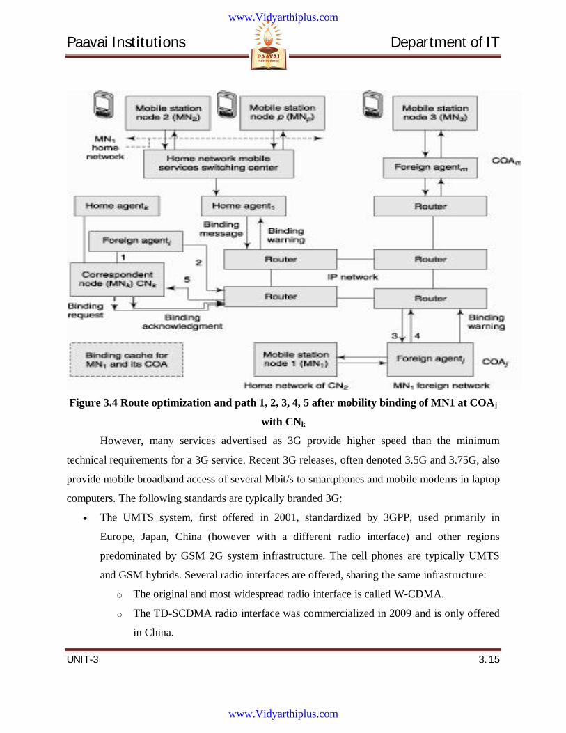
Paavai Institutions Department of IT
UNIT-3 3. 15
Figure 3.4 Route optimization and path 1, 2, 3, 4, 5 after mobility binding of MN1 at COAj
with CNk
However, many services advertised as 3G provide higher speed than the minimum
technical requirements for a 3G service. Recent 3G releases, often denoted 3.5G and 3.75G, also
provide mobile broadband access of several Mbit/s to smartphones and mobile modems in laptop
computers. The following standards are typically branded 3G:
The UMTS system, first offered in 2001, standardized by 3GPP, used primarily in
Europe, Japan, China (however with a different radio interface) and other regions
predominated by GSM 2G system infrastructure. The cell phones are typically UMTS
and GSM hybrids. Several radio interfaces are offered, sharing the same infrastructure:
o The original and most widespread radio interface is called W-CDMA.
o The TD-SCDMA radio interface was commercialized in 2009 and is only offered
in China.
www.Vidyarthiplus.com
www.Vidyarthiplus.com
Paavai Institutions Department of IT
UNIT-3 3. 16
o The latest UMTS release, HSPA+, can provide peak data rates up to 56 Mbit/s in
the downlink in theory (28 Mbit/s in existing services) and 22 Mbit/s in the
uplink.
The CDMA2000 system, first offered in 2002, standardized by 3GPP2, used especially in
North America and South Korea, sharing infrastructure with the IS-95 2G standard. The
cell phones are typically CDMA2000 and IS-95 hybrids. The latest release EVDO Rev B
offers peak rates of 14.7 Mbit/s downstream.
The above systems and radio interfaces are based on spread spectrum radio transmission
technology. While the GSM EDGE standard ("2.9G"), DECT cordless phones and Mobile
WiMAX standards formally also fulfill the IMT-2000 requirements and are approved as 3G
standards by ITU, these are typically not branded 3G, and are based on completely different
technologies.
A new generation of cellular standards has appeared approximately every tenth year since 1G
systems were introduced in 1981/1982. Each generation is characterized by new frequency
bands, higher data rates and non backwards compatible transmission technology. The first
release of the 3GPP Long Term Evolution (LTE) standard does not completely fulfill the ITU 4G
requirements called IMT-Advanced. First release LTE is not backwards compatible with 3G, but
is a pre-4G or 3.9G technology, however sometimes branded "4G" by the service providers. Its
evolution LTE Advanced is a 4G technology. WiMAX is another technology verging on or
marketed as 4G.
Applications of 3G
The bandwidth and location information available to 3G devices gives rise to applications not
previously available to mobile phone users. Some of the applications are:
Mobile TV
Video on demand
Videoconferencing
Telemedicine
Location-based services
www.Vidyarthiplus.com
www.Vidyarthiplus.com
Paavai Institutions Department of IT
UNIT-3 3. 17
3.5 Packet Delivery and Handover Management Correspondent node (CN) is an MN or a fixed IP host linked to a router, which
communicates IP packets to another MN in a home or foreign network (when on visit).
Case 1: CN a fixed node and MNl at the home network
• CN message transmits for connection establishment or a packet using the IP protocol
• HAl (the home agent for MNl) receives the message or packet and, using the information that
the destined MNl is at the home network itself, it delivers the message or packet to MNl
• Receives the response message or packet from MNl
• Delivers it to the CN using the IP protocol
Case 2: CN an MNk and MNl both at home networks with agents HAk and HAl
• MNk message for connection establishment or a packet using the IP protocol transmits through
HAk.
• Same way as in case 1
• The packet delivers to HAl and then to MNl
• MNl response like in case 1
• HAk and HAl deliver the packets from one end to another and vice versa by just forwarding the
packets to their respective MNs using the IP protocol
Case 3: CN a fixed node and MNl is at a foreign network
• CN transmits a message for connection establishment or a packet using the IP protocol
• As in case 1
• HAl receives the packets and uses the information that the destined mobile node MNl is not at
the home network and is presently visiting a foreign network and is reachable via a foreign agent
FAj.
• HAl encapsulates the received IP packet using a new header
• Care-of address (COA) at the new header over the IP packet sent by HAl
• Handover─ Packet encapsulated with the new header with COA transmits to FAj by tunneling
www.Vidyarthiplus.com
www.Vidyarthiplus.com
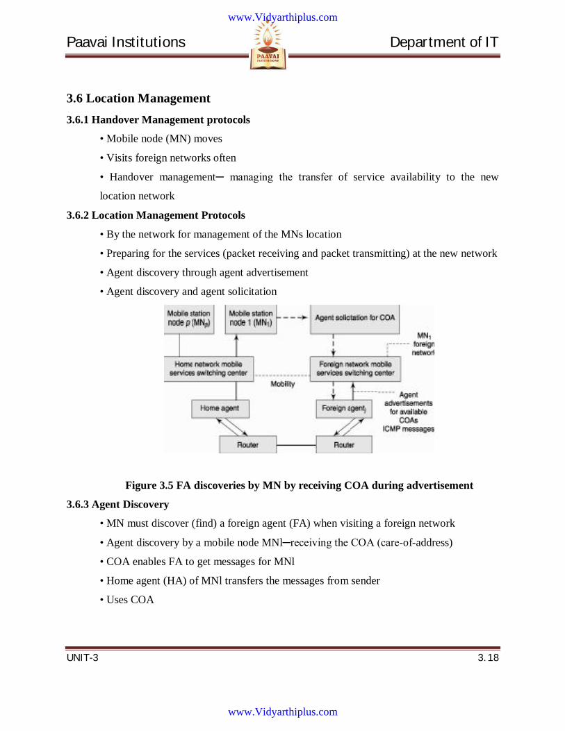
Paavai Institutions Department of IT
UNIT-3 3. 18
3.6 Location Management 3.6.1 Handover Management protocols
• Mobile node (MN) moves
• Visits foreign networks often
• Handover management─ managing the transfer of service availability to the new
location network
3.6.2 Location Management Protocols
• By the network for management of the MNs location
• Preparing for the services (packet receiving and packet transmitting) at the new network
• Agent discovery through agent advertisement
• Agent discovery and agent solicitation
Figure 3.5 FA discoveries by MN by receiving COA during advertisement
3.6.3 Agent Discovery
• MN must discover (find) a foreign agent (FA) when visiting a foreign network
• Agent discovery by a mobile node MNl─receiving the COA (care-of-address)
• COA enables FA to get messages for MNl
• Home agent (HA) of MNl transfers the messages from sender
• Uses COA
www.Vidyarthiplus.com
www.Vidyarthiplus.com
Paavai Institutions Department of IT
UNIT-3 3. 19
Steps 1 and 2 in the protocol for discovering an agent
1. Listen to an advertisement (ICMP message) from an agent
2. Proceed to step 3 if the advertisement is found, else solicit the agent from the routers
•If agent found, then proceed to step 3, else repeat the step Steps 3 and 4 in the
protocol for discovering an agent
3. If the COA discovered from the message is found to be the same as the previous COA,
go back to step 1, else proceed to step 4
4. If the discovered COA is the same as the home network, deregister at this network and
go back to step 1, else if the current COA is a new COA then register with the new COA
3.6.4 Agent advertisements
• Agent advertisements─ essentially ICMP messages
• Sent to a number of addresses ICMP message options and words
• Added mobility extension fields in the ICMP header
3.6.5 Header extension
• One 32-bit word format ─ First byte 00010000
• Second byte for length
• Length = 2 words + number of COAs specified in the extension to which the ICMP
message is to be sent + two bytes for the 16-bit sequence number (for the ICMP message
advertised
• Two-byte lifetime in second plus 8 bits for flags
• Remaining byte is not used ─ reserved for any future requirements of modifications or
specification expansion in ICMP
• Lifetime─ during which the MN can register with the new COA (step 4 in agent
discovery)
• For the COA addresses for the MN at that agent
3.6.6 Co-located COA
• COA when the MN acquires temporarily an additional IP address while on visit to a
new network
• Else the COA is the same IP address for that MN while on visit and when at home FA.
www.Vidyarthiplus.com
www.Vidyarthiplus.com

Paavai Institutions Department of IT
UNIT-3 3. 20
• Obtains the co-located COA using the dynamic host configuration protocol (DHCP)
3.6.7 Flags
• Flag1─ whether the COA is a co-located COA
• Flag2─ whether the advertising agent is the HA
• Flag3─ whether the advertising agent is an FA
• Flag4─ specifies whether there is reverse tunneling support by the FA for encapsulation
and sending packets by tunneling to the HA
• Flag5─ specifies whether the encapsulation method is generic
• Flag6─ specifies whether the encapsulation method is a minimal mandatory method
• Flag7─specifies if the agent is busy and cannot register the visiting MN
3.6.8 Agent solicitation
• A method by which an MN visiting a network discovers the FA and the COA in case
COA not found from advertisements
• If an advertisement is not listened to, solicitation can be done three times at 1 s intervals
• Later this interval can be increased
3.7 Registration Registration after an MN discovering FA for service and finding a COA
• Needed for the service of receiving and transmitting of IP packets with the new agent
FA
• For creating a tunnel between HAl and FAj
3.7.1 Function of HA after registration
• To encapsulate the IP packets and transmit them to the discovered FA (through
tunneling), whenever a CN (corresponding node) communicates with the MN
Deregistration for the receiving and transmitting of IP packets
• Also needed with the HA (step 4 of agent discovery in the protocol)
www.Vidyarthiplus.com
www.Vidyarthiplus.com
Paavai Institutions Department of IT
UNIT-3 3. 21
3.7.2 Registration steps
• Requests and replies are made by the MN, FA, and HA using a UDP datagram • Let us
assume that the MN has IP address of the HA • If not, then the MN broadcasts the
registration request to a paging area
• The HAs then send the registration replies
• The MN requests one of the HAs (out of those which reply) for registration
Step 1 for registration at an agent
1. The MN sends a registration request to FA
• FA sends that request to the HA
• When the COA is a co-located COA, then the request sent directly to the HA
Step 2 for registration at an agent
2. The HA binds itself for mobility (binds itself for encapsulating and tunneling
the packets to the MN through a new FA)
• The binding period equals the lifetime of the COA
Step 3 for registration at an agent
3. The MN registers again before the binding period expires
• When it moves to another foreign network
• When it returns back to the home network
Step 4 for registration at an agent
4. The HA sends a registration reply to the FA and the FA to the MN
• The MN checks whether the reply shows successful registration
3.7.3 Registration
• Success─ mobility binding now exists from the HA to FA
• Failure ─ when there are too many tunnels created at the HA and the HA does not have
the resources to handle new requests or there is an authentication failure or the HA not
reachable to the FA
www.Vidyarthiplus.com
www.Vidyarthiplus.com
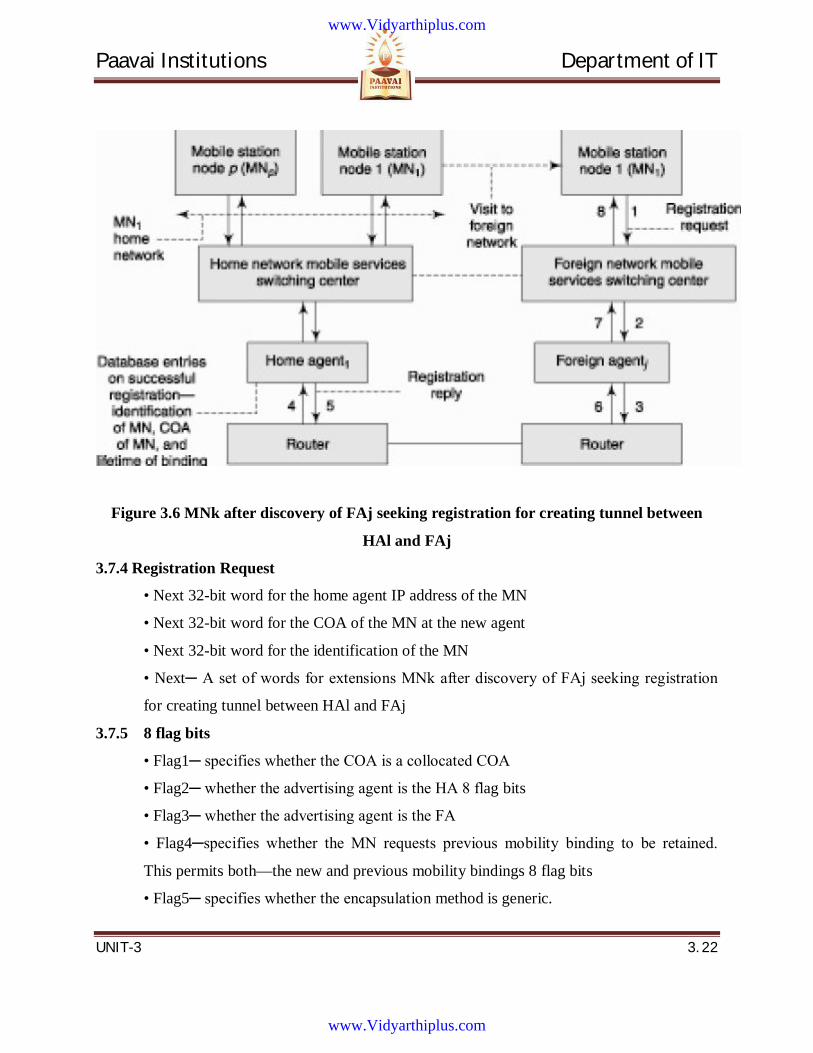
Paavai Institutions Department of IT
UNIT-3 3. 22
Figure 3.6 MNk after discovery of FAj seeking registration for creating tunnel between
HAl and FAj
3.7.4 Registration Request
• Next 32-bit word for the home agent IP address of the MN
• Next 32-bit word for the COA of the MN at the new agent
• Next 32-bit word for the identification of the MN
• Next─ A set of words for extensions MNk after discovery of FAj seeking registration
for creating tunnel between HAl and FAj
3.7.5 8 flag bits
• Flag1─ specifies whether the COA is a collocated COA
• Flag2─ whether the advertising agent is the HA 8 flag bits
• Flag3─ whether the advertising agent is the FA
• Flag4─specifies whether the MN requests previous mobility binding to be retained.
This permits both—the new and previous mobility bindings 8 flag bits
• Flag5─ specifies whether the encapsulation method is generic.
www.Vidyarthiplus.com
www.Vidyarthiplus.com
Paavai Institutions Department of IT
UNIT-3 3. 23
• Flag6─ specifies whether the encapsulation method is a minimal mandatory method 8
flag bits
• Flag7─ specifies whether the MN wishes to receive broadcast (multicast) messages,
which the HA receives for tunneling to the new FA. If not, then the broadcast messages
are filtered at the HA
• Flag8─ specify if there is reverse tunneling support from the FA Words after UDP
header in the
3.7.6 Registration Reply
• 32-bit word with first byte = 00000011, 8 bits for a code specifying the result of
registration, and two bytes for the lifetime (in seconds)
• Next 32-bit word for the home IP address of the MN Words after UDP header in the
• Next 32-bit word for the home agent IP address of the MN
• Next 32-bit word for identification of the MN
• Next a set of words for extensions
3.7.7 New database entry fields after registration at the HA
1. ID for identification of MN
2. COA of the MN
3. Lifetime of binding to tunnel the packets to the MN’s COA
When the binding life expires the tunnel is not forwarding from the HA to the FA using
the COA. Database Entries in the fields at the FA after registration at the HA
(a) MN identification field
(b) Home IP address of the MN
(c) IP address of the HA
(d) MN link layer address for sending and receiving packets and messages to and from
the MN
(e) UDP source port of the registration request
(f) Received identification of the MN
(g) COA of the MN and lifetime of binding to tunnel the packets to the MN’s COA
(h) Remaining lifetime
www.Vidyarthiplus.com
www.Vidyarthiplus.com
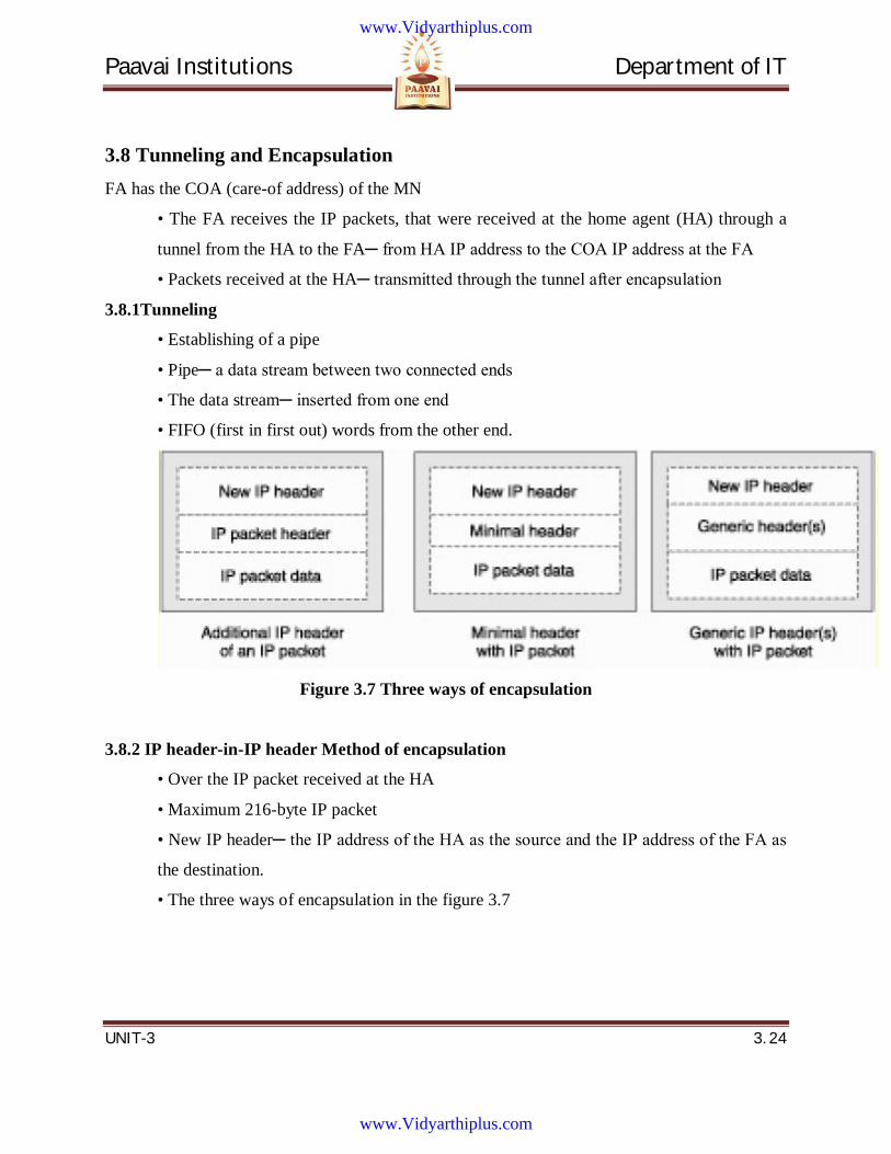
Paavai Institutions Department of IT
UNIT-3 3. 24
3.8 Tunneling and Encapsulation FA has the COA (care-of address) of the MN
• The FA receives the IP packets, that were received at the home agent (HA) through a
tunnel from the HA to the FA─ from HA IP address to the COA IP address at the FA
• Packets received at the HA─ transmitted through the tunnel after encapsulation
3.8.1Tunneling
• Establishing of a pipe
• Pipe─ a data stream between two connected ends
• The data stream─ inserted from one end
• FIFO (first in first out) words from the other end.
Figure 3.7 Three ways of encapsulation
3.8.2 IP header-in-IP header Method of encapsulation
• Over the IP packet received at the HA
• Maximum 216-byte IP packet
• New IP header─ the IP address of the HA as the source and the IP address of the FA as
the destination.
• The three ways of encapsulation in the figure 3.7
www.Vidyarthiplus.com
www.Vidyarthiplus.com

Paavai Institutions Department of IT
UNIT-3 3. 25
Figure 3.8 Two tunnels Tlj and Tkk
Figure 3.9 A tunnel between the HA and FA to carry the encapsulated packet
3.8.3 Format of Encapsulated data
• First 32-bit word to specify the IP version (IPv4 or IPv6 for Internet or broadband
Internet), length of header (= 5 words), precedence of the packet, and total packet-length
(which is now 5 words more than that of IP packet received at the HA)
• Second 32-bit word, to specify the ID for the packet, flags, and fragment offset for the
same packet ID
www.Vidyarthiplus.com
www.Vidyarthiplus.com
Paavai Institutions Department of IT
UNIT-3 3. 26
• Third 32-bit word, to specify the time-to live (number of attempts to hop before expiry
of packets at the network), type of protocol, checksum of the header (for finding
transmission errors, if any)
• Fourth 32-bit word (four decimal numbers separated by dots and each less than 256) to
specify the IP address of the home agent
• Fifth 32-bit word (four decimal numbers separated by dots and each less than 256) to
specify the IP address of the destination COA (care-of address)
• sixth to tenth words are the IP header of 5 words with the fourth word as the IP address
of the correspondent node (CN), and the fifth word as the IP address of the MN
3.8.4 IP header-in-IP header encapsulation Format of Encapsulated data
IP Packet data received from the transport layer at the correspondent node, each
packet has a maximum of 216 bytes
3.8.5 Redundancy in IP header-in-IP header method
• First words in the new IP header (of five words) and the IP packet header (of five
words) are the same and are duplicating in case of IP-in-IP encapsulation
3.8.6 Minimum Encapsulation (ME) method by IP header of an IP Packet
• Combines header of 10 words specified into 7 or 8 words
• The 6th and 7th words in the 6th item of the new IP header are not present in ME as
both words are mere repetitions in ME method by IP header to an IP Packet
• The 8th word in the 6th item─ changed and now specifies the type of protocol, a one bit
flag, seven reserved bits, and a 16- bit checksum of the modified three-word IP header
(from the original five) for finding transmission error, if any.
• The 9th word in the 6th item─ changed and now specifies (instead of the CN IP
address) the MN IP address (which was earlier specified by the 10th word).
• The 10th word in the 6th item─ changed and now specifies (instead of the MN IP
address) the CN IP address in case the flag bit is set to 1 and the 10th word in the 6th
item is removed in case the flag bit is set to 0. Action by FA in case of ME method
• Reads the first five words in ME
• Transmits the packet to the MN using the COA
www.Vidyarthiplus.com
www.Vidyarthiplus.com
Paavai Institutions Department of IT
UNIT-3 3. 27
• The MN IP address is specified by the 7th or the 8th word, depending upon the flag bit.
3.8.7 Deficiencies in the IP header-in-IP header and ME methods
(a) Routing information for tunneling not given
(b) No provision for recursive encapsulations
• Recursive encapsulations needed when the tunnel transmits multiple pieces of
information for the MN and each piece of information encapsulates in one
protocol
(c) No provision for a key that can be used for authentication or encryption
3.8.8 Generic Routing Encapsulation (GRE) by IP header of an IP Packet
• One or more GRE headers depending on the number of recursions required to send
multiple pieces of information
3.8.9 Tunnel characteristics
• The tunnel does not need an extra hop (attempt) so time-to-live can be set to 1 • Tunnel
does not get blocked like routers due to external IP address transmissions
• Has fixed source and destination endpoints
3.8.10 GRE by IP header of an IP Packet
• Same as the 1st to 5th words in the 1st to 5th items of the new IP header
• Time-to-live is however set as 1
• Results in once-only forwarding to the FA by the HA
3.8.11 GRE (GRE) Header(s)
• The 6th 32-bit word in encapsulation and the 1st word of the first GRE header
• 16-bit flags─ bits to define the number of recursions, reserve bits, and version bits
• Next 16 bits─ specify the protocol for encapsulating the information sent with the GRE
header
• The 7th word─ specifies a 16-bit checksum and a 16-bit offset Both are optional as
indicated by the flag bits used to define these options
• The 8th word─ a 32-bit key
• Optional as indicated by the flag bit to used define the key-option
• The key at the GRE header─ enables authentication or encryption at the FA
www.Vidyarthiplus.com
www.Vidyarthiplus.com

Paavai Institutions Department of IT
UNIT-3 3. 28
• The 9th word─ specifies 32-bit sequence number information
• Optional as indicated by the flag bit used to define the sequencing-option
• Sequencing at the GRE header enables the FA to rearrange the packets sent by the HA
• The 10th word─ specifies 32-bit routing information
• Optional as indicated by the flag bit used to define the routing-option
• Routing at the GRE header enables use of routing information at the FA
• 11th word onwards─ , if number of recursions are defined in the first word of the GRE
header, then the next GRE header is inserted before the IP header and IP data sent by the
HA
• If number of recursions specified in the 11th word in the GRE header is two, then the
next two GRE headers are also inserted before the IP header and IP data sent by the HA
3.8.12 IP Header and IP Packet data
• This part remains the same as that in the un-encapsulated IP header and the data
received from the CN (correspondent node) IP packet at the HA. The first word has 5 flag
bits and three recursion-number-defining bits
• The five flag bits are—checksum option flag, sequence number field option flag, key-
option flag, and source-routing option flag
3.8.13 Source routing
• Source of a packet provides the route information
• Router uses the routing information word for routing a packet
3.9 Route Optimization Mobile IP network employing home and foreign agents FAk and FAj
• Packet delivers to and from the MNk at a foreign network with FAk and MN1 at
the foreign network with FAj is shown in figure 3.10.
Example
• Assume that MNl visiting a foreign network which happens to be the home
network of CN2 as shown in figure 3.11. CN2 is very close to CN.
www.Vidyarthiplus.com
www.Vidyarthiplus.com
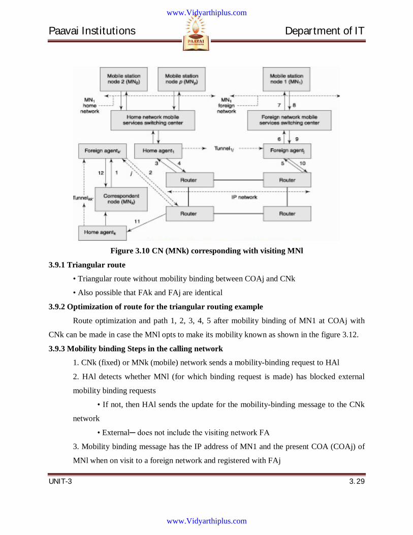
Paavai Institutions Department of IT
UNIT-3 3. 29
Figure 3.10 CN (MNk) corresponding with visiting MNl
3.9.1 Triangular route
• Triangular route without mobility binding between COAj and CNk
• Also possible that FAk and FAj are identical
3.9.2 Optimization of route for the triangular routing example
Route optimization and path 1, 2, 3, 4, 5 after mobility binding of MN1 at COAj with
CNk can be made in case the MNl opts to make its mobility known as shown in the figure 3.12.
3.9.3 Mobility binding Steps in the calling network
1. CNk (fixed) or MNk (mobile) network sends a mobility-binding request to HAl
2. HAl detects whether MNl (for which binding request is made) has blocked external
mobility binding requests
• If not, then HAl sends the update for the mobility-binding message to the CNk
network
• External─ does not include the visiting network FA
3. Mobility binding message has the IP address of MN1 and the present COA (COAj) of
MNl when on visit to a foreign network and registered with FAj
www.Vidyarthiplus.com
www.Vidyarthiplus.com
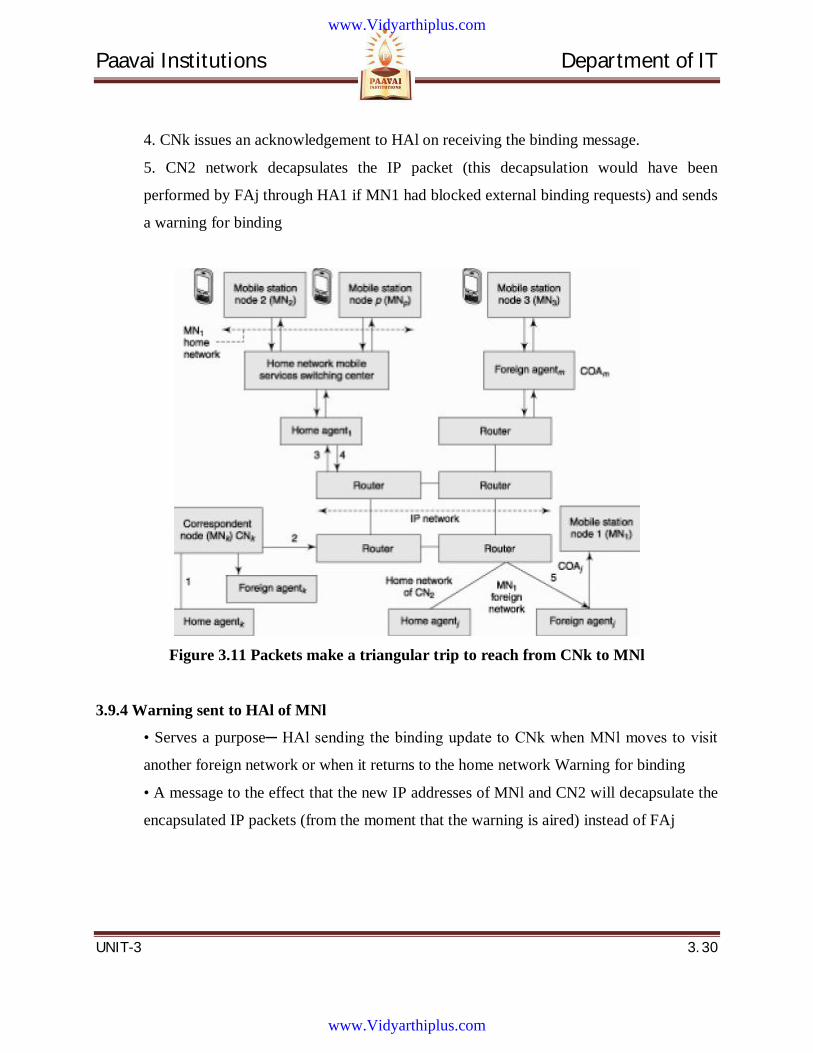
Paavai Institutions Department of IT
UNIT-3 3. 30
4. CNk issues an acknowledgement to HAl on receiving the binding message.
5. CN2 network decapsulates the IP packet (this decapsulation would have been
performed by FAj through HA1 if MN1 had blocked external binding requests) and sends
a warning for binding
Figure 3.11 Packets make a triangular trip to reach from CNk to MNl
3.9.4 Warning sent to HAl of MNl
• Serves a purpose─ HAl sending the binding update to CNk when MNl moves to visit
another foreign network or when it returns to the home network Warning for binding
• A message to the effect that the new IP addresses of MNl and CN2 will decapsulate the
encapsulated IP packets (from the moment that the warning is aired) instead of FAj
www.Vidyarthiplus.com
www.Vidyarthiplus.com
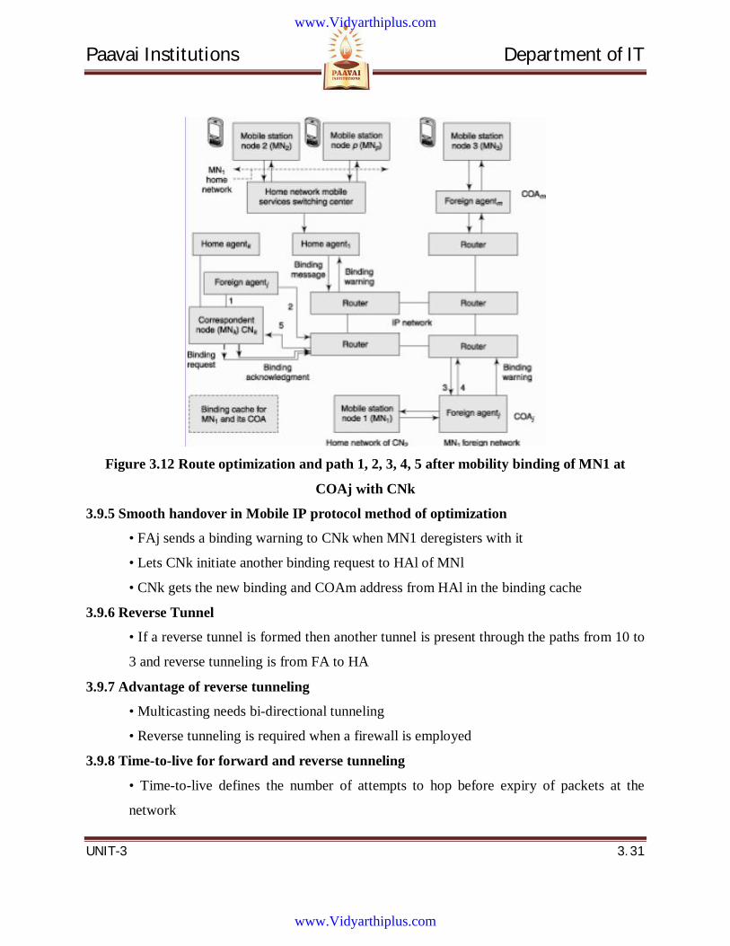
Paavai Institutions Department of IT
UNIT-3 3. 31
Figure 3.12 Route optimization and path 1, 2, 3, 4, 5 after mobility binding of MN1 at
COAj with CNk
3.9.5 Smooth handover in Mobile IP protocol method of optimization
• FAj sends a binding warning to CNk when MN1 deregisters with it
• Lets CNk initiate another binding request to HAl of MNl
• CNk gets the new binding and COAm address from HAl in the binding cache
3.9.6 Reverse Tunnel
• If a reverse tunnel is formed then another tunnel is present through the paths from 10 to
3 and reverse tunneling is from FA to HA
3.9.7 Advantage of reverse tunneling
• Multicasting needs bi-directional tunneling
• Reverse tunneling is required when a firewall is employed
3.9.8 Time-to-live for forward and reverse tunneling
• Time-to-live defines the number of attempts to hop before expiry of packets at the
network
www.Vidyarthiplus.com
www.Vidyarthiplus.com
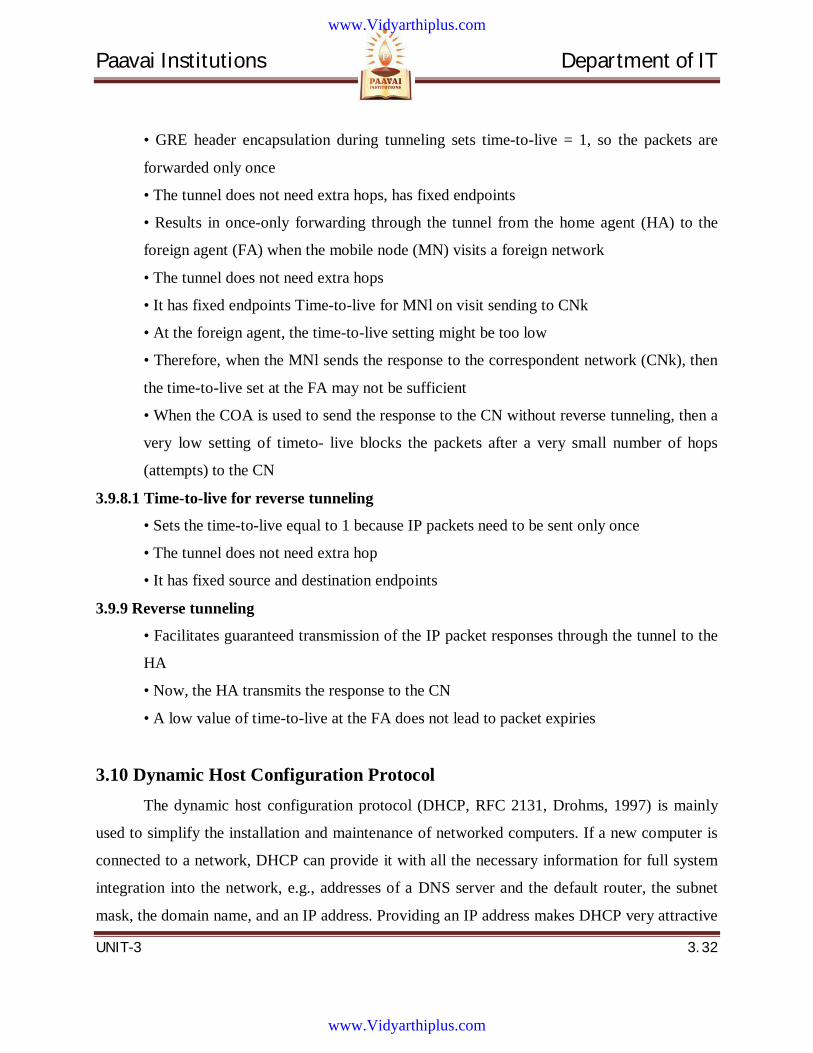
Paavai Institutions Department of IT
UNIT-3 3. 32
• GRE header encapsulation during tunneling sets time-to-live = 1, so the packets are
forwarded only once
• The tunnel does not need extra hops, has fixed endpoints
• Results in once-only forwarding through the tunnel from the home agent (HA) to the
foreign agent (FA) when the mobile node (MN) visits a foreign network
• The tunnel does not need extra hops
• It has fixed endpoints Time-to-live for MNl on visit sending to CNk
• At the foreign agent, the time-to-live setting might be too low
• Therefore, when the MNl sends the response to the correspondent network (CNk), then
the time-to-live set at the FA may not be sufficient
• When the COA is used to send the response to the CN without reverse tunneling, then a
very low setting of timeto- live blocks the packets after a very small number of hops
(attempts) to the CN
3.9.8.1 Time-to-live for reverse tunneling
• Sets the time-to-live equal to 1 because IP packets need to be sent only once
• The tunnel does not need extra hop
• It has fixed source and destination endpoints
3.9.9 Reverse tunneling
• Facilitates guaranteed transmission of the IP packet responses through the tunnel to the
HA
• Now, the HA transmits the response to the CN
• A low value of time-to-live at the FA does not lead to packet expiries
3.10 Dynamic Host Configuration Protocol The dynamic host configuration protocol (DHCP, RFC 2131, Drohms, 1997) is mainly
used to simplify the installation and maintenance of networked computers. If a new computer is
connected to a network, DHCP can provide it with all the necessary information for full system
integration into the network, e.g., addresses of a DNS server and the default router, the subnet
mask, the domain name, and an IP address. Providing an IP address makes DHCP very attractive
www.Vidyarthiplus.com
www.Vidyarthiplus.com
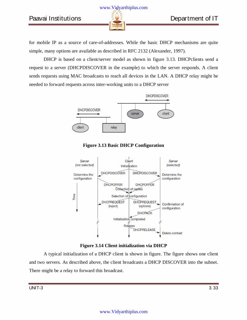
Paavai Institutions Department of IT
UNIT-3 3. 33
for mobile IP as a source of care-of-addresses. While the basic DHCP mechanisms are quite
simple, many options are available as described in RFC 2132 (Alexander, 1997).
DHCP is based on a client/server model as shown in figure 3.13. DHCPclients send a
request to a server (DHCPDISCOVER in the example) to which the server responds. A client
sends requests using MAC broadcasts to reach all devices in the LAN. A DHCP relay might be
needed to forward requests across inter-working units to a DHCP server
Figure 3.13 Basic DHCP Configuration
Figure 3.14 Client initialization via DHCP
A typical initialization of a DHCP client is shown in figure. The figure shows one client
and two servers. As described above, the client broadcasts a DHCP DISCOVER into the subnet.
There might be a relay to forward this broadcast.
www.Vidyarthiplus.com
www.Vidyarthiplus.com
Paavai Institutions Department of IT
UNIT-3 3. 34
In the case shown, two servers receive this broadcast and determine the configuration
they can offer to the client. One example for this could be the checking of available IP addresses
and choosing one for the client. Servers reply to the client’s request with DHCPOFFER and offer
a list of configuration parameters.
The client can now choose one of the configurations offered. The client in turn replies to
the servers, accepting one of the configurations and rejecting the others using DHCPREQUEST.
If a server receives a DHCPREQUEST with a rejection, it can free the reserved configuration for
other possible clients. The server with the configuration accepted by the client now confirms the
configuration with DHCPACK. This completes the initialization phase.
If a client leaves a subnet, it should release the configuration received by the server using
DHCPRELEASE. Now the server can free the context stored for the client and offer the
configuration again. The configuration a client gets from a server is only leased for a certain
amount of time, it has to be reconfirmed from time to time. Otherwise the server will free the
configuration. This timeout of configuration helps in the case of crashed nodes or nodes moved
away without releasing the context.
DHCP is a good candidate for supporting the acquisition of care-of addresses for mobile
nodes. The same holds for all other parameters needed, such as addresses of the default router,
DNS servers, the timeserver etc. A DHCP server should be located in the subnet of the access
point of the mobile node, or at least a DHCP relay should provide forwarding of the messages.
RFC 3118 specifies authentication for DHCP messages which is needed to protect mobile nodes
from malicious DHCP servers. Without authentication, the mobile node cannot trust a DHCP
server, and the DHCP server cannot trust the mobile node.
www.Vidyarthiplus.com
www.Vidyarthiplus.com
Paavai Institutions Department of IT
UNIT-3 3. 35
3.11 Question Bank PART – A (2 MARKS)
1. What are the requirements of mobile IP?
2. Mention the different entities in a mobile IP.
3. What do you mean by mobility binding?
4. Define a tunnel.
5. What is encapsulation?
6. What is decapsulation?
7. Define an outer header
8. Define an inner header.
9. What is meant by generic routing encapsulation?
10. What is the use of network address translation?
11. Define triangular routing.
12. What is meant by a binding cache?
13. Define binding request.
14. What is known as Binding update?
15. Explain binding acknowledgement.
16. Define binding warning.
17. Explain cellular IP.
18. What are the advantages of cellular IP?
19. What is known as mobility anchor point?
20. Explain destination sequence distance vector routing.
21. What are the two things added to the distance vector algorithm?
22. How the dynamic source routing does divide the task of routing into two separate problems?
www.Vidyarthiplus.com
www.Vidyarthiplus.com
Paavai Institutions Department of IT
UNIT-3 3. 36
PART – B (16 Marks)
1. What are the requirements of a mobile IP?
2. Describe Dynamic host configuration protocol.
3. Discuss the routing algorithm in ad-hoc network
4. What are the entities in mobile IP?
5. Discuss how optimization in achieved in mobile IP
6. Explain tunneling and encapsulation in mobile IP.
7. Explain how dynamic source routing protocols handles routing with an example.
8. How can DHCP be used for mobility and support of mobile IP?
www.Vidyarthiplus.com
www.Vidyarthiplus.com
Paavai Institutions Department of IT
UNIT-4 4. 1
UNIT 4
MOBILE TRANSPORT LAYER
www.Vidyarthiplus.com
www.Vidyarthiplus.com
Paavai Institutions Department of IT
UNIT-4 4. 2
CONTENTS 4.1 Classical TCP Improvements
4.2 Indirect TCP
4.3 Snooping TCP
4.4 Mobile TCP
4.5 Fast Retransmit/Fast Recovery
4.6 Transmission/Time-Out Freezing
4.7 Selective Retransmission
4.8 Transaction-Oriented TCP
4.9 Mobile Operating Systems
4.10 Palm OS
4.11 Windows CE
4.12 Symbion OS
4.13 Linux for Mobile Devices
4.14 Question Bank
www.Vidyarthiplus.com
www.Vidyarthiplus.com
Paavai Institutions Department of IT
UNIT-4 4. 3
TECHNICAL TERMS
1. TCP is Transmission Control Protocol. It provides reliable, ordered delivery of a stream
of bytes from a program on one computer to another program on another
computer.(Connection oriented)
2. Internet Protocol (IP) is the principal communications protocol used for
relaying datagram across an internetwork using the Internet Protocol Suite.
3. IP Addressing refers to how end hosts are assigned IP addresses and how sub networks
of IP host addresses are divided and grouped.
4. IP routing is performed by all hosts, but most importantly by routers, which typically use
either interior gateway protocols (IGPs) or external gateway protocols (EGPs) to decide
how to move datagram’s among networks.
5. Packets are the IP works by exchanging pieces of information called packets
6. UDP (User Datagram Protocol) is a communications protocol that offers a limited
amount of service when messages are exchanged between computers in a network that
uses the Internet Protocol (IP). (Connectionless protocol)
7. Snooping is unauthorized access to another person's or company's data.
8. Eavesdropping is the unauthorized real-time interception of a private communication,
such as a phone call, instant message, video conference or fax transmission.
9. Datagram is a basic transfer unit associated with a packet-switched network in which the
delivery, arrival time, and order of arrival are not guaranteed by the network service.
10. An operating system (OS) is a set of software that manages computer
hardware resources and provides common services for computer programs. The operating
system is a vital component of the system software in a computer system. Application
programs require an operating system to function.
11. Palm OS (also known as Garnet OS) is a mobile operating system initially developed
by Palm, Inc., for personal digital assistants (PDAs) in 1996. Palm OS is designed for
ease of use with a touch screen-based graphical user interface. It is provided with a suite
of basic applications for personal information management.
www.Vidyarthiplus.com
www.Vidyarthiplus.com
Paavai Institutions Department of IT
UNIT-4 4. 4
4. MOBILE TRANSPORT LAYER
4.1 Conventional TCP/IP protocols Together with the introduction of WLANs in the mid-nineties several research projects
were started with the goal to increase TCP’s performance in wireless and mobile environments.
4.2 Indirect TCP
Two competing insights led to the development of indirect TCP (I-TCP) (Bakre, 1995).
One is that TCP performs poorly together with wireless links; the other is that TCP within the
fixed network cannot be changed. I-TCP segments a TCP connection into a fixed part and a
wireless part. Figure 4.1 shows an example with a mobile host connected via a wireless link and
an access point to the ‘wired’ internet where the correspondent host resides. The correspondent
node could also use wireless access. The following would then also be applied to the access link
of the correspondent host.
Standard TCP is used between the fixed computer and the access point. No computer in
the internet recognizes any changes to TCP. Instead of the mobile host, the access point now
terminates the standard TCP connection, acting as a proxy. This means that the access point is
now seen as the mobile host for the fixed host and as the fixed host for the mobile host. Between
the access point and the mobile host a special TCP, adapted to wireless links, is used. However,
changing TCP for the wireless link is not a requirement. Even an unchanged TCP can benefit
from the much shorter round trip time, starting retransmission much faster.
A good place for segmenting the connection between mobile host and correspondent host
is at the foreign agent of mobile IP. The foreign agent controls the mobility of the mobile host
anyway and can also hand over the connection to the next foreign agent when the mobile host
moves on.
www.Vidyarthiplus.com
www.Vidyarthiplus.com
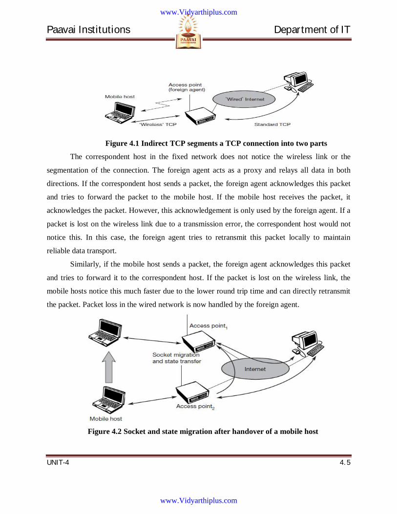
Paavai Institutions Department of IT
UNIT-4 4. 5
Figure 4.1 Indirect TCP segments a TCP connection into two parts
The correspondent host in the fixed network does not notice the wireless link or the
segmentation of the connection. The foreign agent acts as a proxy and relays all data in both
directions. If the correspondent host sends a packet, the foreign agent acknowledges this packet
and tries to forward the packet to the mobile host. If the mobile host receives the packet, it
acknowledges the packet. However, this acknowledgement is only used by the foreign agent. If a
packet is lost on the wireless link due to a transmission error, the correspondent host would not
notice this. In this case, the foreign agent tries to retransmit this packet locally to maintain
reliable data transport.
Similarly, if the mobile host sends a packet, the foreign agent acknowledges this packet
and tries to forward it to the correspondent host. If the packet is lost on the wireless link, the
mobile hosts notice this much faster due to the lower round trip time and can directly retransmit
the packet. Packet loss in the wired network is now handled by the foreign agent.
Figure 4.2 Socket and state migration after handover of a mobile host
www.Vidyarthiplus.com
www.Vidyarthiplus.com
Paavai Institutions Department of IT
UNIT-4 4. 6
There are several advantages with I-TCP:
I-TCP does not require any changes in the TCP protocol as used by the hosts in the fixed
network or other hosts in a wireless network that do not use this optimization. All current
optimizations for TCP still work between the foreign agent and the correspondent host.
Due to the strict partitioning into two connections, transmission errors on the wireless
link, i.e., lost packets, cannot propagate into the fixed network. Without partitioning,
retransmission of lost packets would take place between mobile host and correspondent host
across the whole network. Now only packets in sequence, without gaps leave the foreign agent.
It is always dangerous to introduce new mechanisms into a huge network such as the
internet without knowing exactly how they will behave. However, new mechanisms are needed
to improve TCP performance (e.g., disabling slow start under certain circumstances), but with I-
TCP only between the mobile host and the foreign agent. Different solutions can be tested or
used at the same time without jeopardizing the stability of the internet. Furthermore, optimizing
of these new mechanisms is quite simple because they only cover one single hop.
Assume that the short delay between the mobile host and foreign agent could be
determined and was independent of other traffic streams. An optimized TCP could use precise
time-outs to guarantee retransmission as fast as possible. Even standard TCP could benefit from
the short round trip time, so recovering faster from packet loss. Delay is much higher in a typical
wide area wireless network than in wired networks due to FEC and MAC. GSM has a delay of
up to 100 ms circuit switched, 200 ms and more packet switched (depending on packet size and
current traffic). This is even higher than the delay on transatlantic links.
Partitioning into two connections also allows the use of a different transport layer
protocol between the foreign agent and the mobile host or the use of compressed headers etc.
The foreign agent can now act as a gateway to translate between the different protocols.
But the idea of segmentation in I-TCP also comes with some disadvantages:
The loss of the end-to-end semantics of TCP might cause problems if the foreign agent
partitioning the TCP connection crashes. If a sender receives an acknowledgement, it assumes
that the receiver got the packet. Receiving an acknowledgement now only means (for the mobile
www.Vidyarthiplus.com
www.Vidyarthiplus.com
Paavai Institutions Department of IT
UNIT-4 4. 7
host and a correspondent host) that the foreign agent received the packet. The correspondent
node does not know anything about the partitioning, so a crashing access node may also crash
applications running on the correspondent node assuming reliable end-to-end delivery.
In practical use, increased handover latency may be much more problematic. All packets
sent by the correspondent host are buffered by the foreign agent besides forwarding them to the
mobile host (if the TCP connection is split at the foreign agent). The foreign agent removes a
packet from the buffer as soon as the appropriate acknowledgement arrives. If the mobile host
now performs a handover to another foreign agent, it takes a while before the old foreign agent
can forward the buffered data to the new foreign agent. During this time more packets may
arrive. All these packets have to be forwarded to the new foreign agent first, before it can start
forwarding the new packets redirected to it.
The foreign agent must be a trusted entity because the TCP connections end at this point.
If users apply end-to-end encryption, e.g., according to RFC 2401 (Kent, 1998a), the foreign
agent has to be integrated into all security mechanisms.
4.3 Snooping TCP One of the drawbacks of I-TCP is the segmentation of the single TCP connection into
two TCP connections. This loses the original end-to-end TCP semantic. The following TCP
enhancement works completely transparently and leaves the TCP end-to-end connection intact.
The main function of the enhancement is to buffer data close to the mobile host to perform fast
local retransmission in case of packet loss. A good place for the enhancement of TCP could be
the foreign agent in the Mobile IP context.
In this approach, the foreign agent buffers all packets with destination mobile host and
additionally ‘snoops’ the packet flow in both directions to recognize acknowledgements
(Balakrishnan, 1995), (Brewer, 1998). The reason for buffering packets toward the mobile node
is to enable the foreign agent to performa local retransmission in case of packet loss on the
wireless link. The foreign agent buffers every packet until it receives an acknowledgement from
the mobile host.
www.Vidyarthiplus.com
www.Vidyarthiplus.com
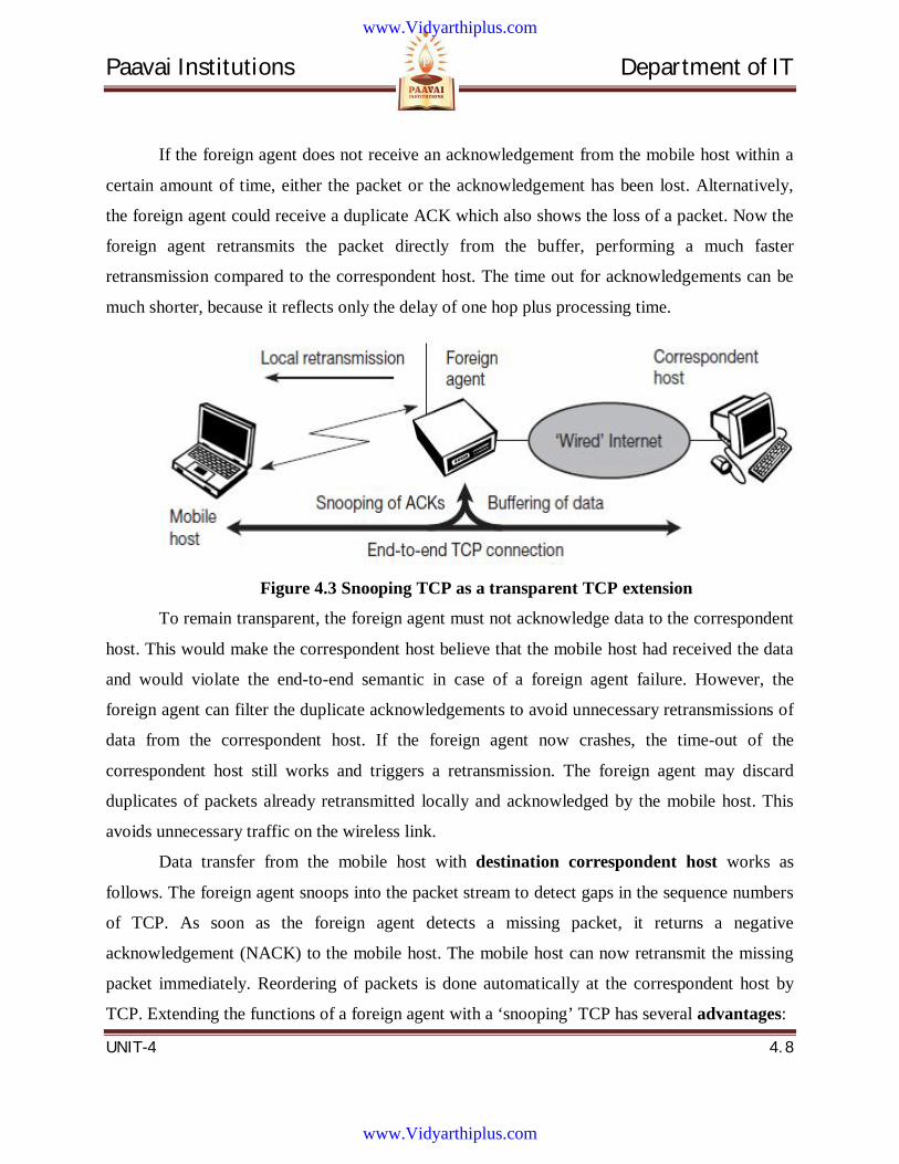
Paavai Institutions Department of IT
UNIT-4 4. 8
If the foreign agent does not receive an acknowledgement from the mobile host within a
certain amount of time, either the packet or the acknowledgement has been lost. Alternatively,
the foreign agent could receive a duplicate ACK which also shows the loss of a packet. Now the
foreign agent retransmits the packet directly from the buffer, performing a much faster
retransmission compared to the correspondent host. The time out for acknowledgements can be
much shorter, because it reflects only the delay of one hop plus processing time.
Figure 4.3 Snooping TCP as a transparent TCP extension
To remain transparent, the foreign agent must not acknowledge data to the correspondent
host. This would make the correspondent host believe that the mobile host had received the data
and would violate the end-to-end semantic in case of a foreign agent failure. However, the
foreign agent can filter the duplicate acknowledgements to avoid unnecessary retransmissions of
data from the correspondent host. If the foreign agent now crashes, the time-out of the
correspondent host still works and triggers a retransmission. The foreign agent may discard
duplicates of packets already retransmitted locally and acknowledged by the mobile host. This
avoids unnecessary traffic on the wireless link.
Data transfer from the mobile host with destination correspondent host works as
follows. The foreign agent snoops into the packet stream to detect gaps in the sequence numbers
of TCP. As soon as the foreign agent detects a missing packet, it returns a negative
acknowledgement (NACK) to the mobile host. The mobile host can now retransmit the missing
packet immediately. Reordering of packets is done automatically at the correspondent host by
TCP. Extending the functions of a foreign agent with a ‘snooping’ TCP has several advantages:
www.Vidyarthiplus.com
www.Vidyarthiplus.com
Paavai Institutions Department of IT
UNIT-4 4. 9
The end-to-end TCP semantic is preserved. No matter at what time the foreign agent
crashes (if this is the location of the buffering and snooping mechanisms), neither the
correspondent host nor the mobile host have an inconsistent view of the TCP connection
as is possible with I-TCP. The approach automatically falls back to standard TCP if the
enhancements stop working.
The correspondent host does not need to be changed; most of the enhancements are in the
foreign agent. Supporting only the packet stream from the correspondent host to the
mobile host does not even require changes in the mobile host.
It does not need a handover of state as soon as the mobile host moves to another foreign
agent. Assume there might still be data in the buffer not transferred to the next foreign
agent. All that happens is a time-out at the correspondent host and retransmission of the
packets, possibly already to the new care-of address.
It does not matter if the next foreign agent uses the enhancement or not. If not, the
approach automatically falls back to the standard solution. This is one of the problems of
I-TCP, since the old foreign agent may have already signaled the correct receipt of data
via acknowledgements to the correspondent host and now has to transfer these packets to
the mobile host via the new foreign agent.
The simplicity of the scheme also results in some disadvantages:
Snooping TCP does not isolate the behavior of the wireless link as well as ITCP.
Assume, for example, that it takes some time until the foreign agent can successfully retransmit a
packet from its buffer due to problems on the wireless link (congestion, interference). Although
the time-out in the foreign agent may be much shorter than the one of the correspondent host,
after a while the time-out in the correspondent host triggers a retransmission.
The problems on the wireless link are now also visible for the correspondent host and not
fully isolated. The quality of the isolation, which snooping TCP offers, strongly depends on the
quality of the wireless link, time-out values, and further traffic characteristics. It is problematic
that the wireless link exhibits very high delays compared to the wired link due to error correction
www.Vidyarthiplus.com
www.Vidyarthiplus.com
Paavai Institutions Department of IT
UNIT-4 4. 10
on layer 2 (factor 10 and more higher). This is similar to ITCP. If this is the case, the timers in
the foreign agent and the correspondent host are almost equal and the approach is almost
ineffective.
Using negative acknowledgements between the foreign agent and the mobile host
assumes additional mechanisms on the mobile host. This approach is no longer transparent for
arbitrary mobile hosts.
All efforts for snooping and buffering data may be useless if certain encryption schemes
are applied end-to-end between the correspondent host and mobile host. Using IP encapsulation
security payload (RFC 2406, (Kent, 1998b)) the TCP protocol header will be encrypted –
snooping on the sequence numbers will no longer work. Retransmitting data from the foreign
agent may not work because many security schemes prevent replay attacks – retransmitting data
from the foreign agent may be misinterpreted as replay. Encrypting end-to-end is the way many
applications work so it is not clear how t his scheme could be used in the future. If encryption is
used above the transport layer (e.g., SSL/TLS) snooping TCP can be used.
4.4 Mobile TCP Dropping packets due to a handover or higher bit error rates is not the only phenomenon
of wireless links and mobility – the occurrence of lengthy and/or frequent disconnections is
another problem. Quite often mobile users cannot connect at all. One example is islands of
wireless LANs inside buildings but no coverage of the whole campus.
What happens to standard TCP in the case of disconnection?
A TCP sender tries to retransmit data controlled by a retransmission timer that
doubles with each unsuccessful retransmission attempt, up to a maximum of one minute
(the initial value depends on the round trip time). This means that the sender tries to
retransmit an unacknowledged packet every minute and will give up after 12
retransmissions.
www.Vidyarthiplus.com
www.Vidyarthiplus.com
Paavai Institutions Department of IT
UNIT-4 4. 11
What happens if connectivity is back ear-lier than this?
No data is successfully transmitted for a period of one minute. The
retransmission time-out is still valid and the sender has to wait. The sender also goes into
slow-start because it assumes congestion.
What happens in the case of I-TCP if the mobile is disconnected?
The proxy has to buffer more and more data, so the longer the period of
disconnection, the more buffer is needed. If a handover follows the disconnection, which
is typical, even more state has to be transferred to the new proxy. The snooping approach
also suffers from being disconnected. The mobile will not be able to send ACKs so,
snooping cannot help in this situation.
The M-TCP (mobile TCP) approach has the same goals as I-TCP and snooping TCP: to
prevent the sender window from shrinking if bit errors or disconnection but not congestion cause
current problems. M-TCP wants to improve overall throughput, to lower the delay, to maintain
end-to-end semantics of TCP, and to provide a more efficient handover. Additionally, M-TCP is
especially adapted to the problems arising from lengthy or frequent disconnections.
M-TCP splits the TCP connection into two parts as I-TCP does. An unmodified TCP is
used on the standard host-supervisory host (SH) connection, while an optimized TCP is used on
the SH-MH connection. The supervisory host is responsible for exchanging data between both
parts similar to the proxy in). The M-TCP approach assumes a relatively low bit error rate on the
wireless link. Therefore, it does not perform caching/retransmission of data via the SH. If a
packet is lost on the wireless link, it has to be retransmitted by the original sender. This
maintains the TCP end-to-end semantics.
The SH monitors all packets sent to the Mobile Host (MH) and ACKs returned from the
MH. If the SH does not receive an ACK for some time, it assumes that the MH is disconnected.
It then chokes the sender by setting the sender’s window size to 0. Setting the window size to 0
forces the sender to go into persistent mode, i.e., the state of the sender will not change no
matter how long the receiver is disconnected. This means that the sender will not try to
www.Vidyarthiplus.com
www.Vidyarthiplus.com
Paavai Institutions Department of IT
UNIT-4 4. 12
retransmit data. As soon as the SH (either the old SH or a new SH) detects connectivity again, it
reopens the window of the sender to the old value. The sender can continue sending at full speed.
This mechanism does not require changes to the sender’s TCP.
The wireless side uses an adapted TCP that can recover from packet loss much faster.
This modified TCP does not use slow start, thus, M-TCP needs a bandwidth manager to
implement fair sharing over the wireless link.
The advantages of M-TCP are
It maintains the TCP end-to-end semantics. The SH does not send any ACK itself but
forwards the ACKs from the MH.
If the MH is disconnected, it avoids useless retransmissions, slow starts or breaking
connections by simply shrinking the sender’s window to 0.1 The reader should be aware
that mobile TCP does not have the same status as mobile IP, which is an internet RFC.
Since it does not buffer data in the SH as I-TCP does, it is not necessary to forward
buffers to a new SH. Lost packets will be automatically retransmitted to the new SH.
The lack of buffers and changing TCP on the wireless part also has some disadvantages:
As the SH does not act as proxy as in I-TCP, packet loss on the wireless link due to bit
errors is propagated to the sender. M-TCP assumes low bit error rates, which is not
always a valid assumption.
A modified TCP on the wireless link not only requires modifications to the MH protocol
software but also new network elements like the bandwidth manager.
4.5 Fast Retransmit/Fast Recovery
TCP concludes congestion and goes into slow start, although there is no congestion. The
mechanisms of fast recovery/fast retransmit a host can use after receiving duplicate
acknowledgements, thus concluding a packet loss without congestion.
The idea presented by Caceres (1995) is to artificially force the fast retransmit behavior
on the mobile host and correspondent host side. As soon as the mobile host registers at a new
www.Vidyarthiplus.com
www.Vidyarthiplus.com
Paavai Institutions Department of IT
UNIT-4 4. 13
foreign agent using mobile IP, it starts sending duplicated acknowledgements to correspondent
hosts. The proposal is to send three duplicates. This forces the corresponding host to go into fast
retransmit mode and not to start slow start, i.e., the correspondent host continues to send with the
same rate it did before the mobile host moved to another foreign agent.
As the mobile host may also go into slow start after moving to a new foreign agent, this
approach additionally puts the mobile host into fast retransmit. The mobile host retransmits all
unacknowledged packets using the current congestion window size without going into slow start.
The advantage of this approach is its simplicity. Only minor changes in the mobile
host’s software already result in a performance increase. No foreign agent or correspondent host
has to be changed.
The main disadvantage of this scheme is the insufficient isolation of packet losses.
Forcing fast retransmission increases the efficiency, but retransmitted packets still have to cross
the whole network between correspondent host and mobile host. If the handover from one
foreign agent to another takes a longer time, the correspondent host will have already started
retransmission. The approach focuses on loss due to handover: packet loss due to problems on
the wireless link is not considered. This approach requires more cooperation between the mobile
IP and TCP layer making it harder to change one without influencing the other.
4.6 Transmission/Time-Out Freezing
While the approaches presented so far can handle short interruptions of the connection,
either due to handover or transmission errors on the wireless link, some were designed for longer
interruptions of transmission. Examples are the use of mobile hosts in a car driving into a tunnel,
which loses its connection to, e.g., a satellite (however, many tunnels and subways provide
connectivity via a mobile phone), or a user moving into a cell with no capacity left over. In this
case, the mobile phone system will interrupt the connection. The reaction of TCP, even with the
enhancements of above, would be a disconnection after a time out.
Quite often, the MAC layer has already noticed connection problems, before the
connection is actually interrupted from a TCP point of view. Additionally, the MAC layer knows
the real reason for the interruption and does not assume congestion, as TCP would. The MAC
www.Vidyarthiplus.com
www.Vidyarthiplus.com
Paavai Institutions Department of IT
UNIT-4 4. 14
layer can inform the TCP layer of an upcoming loss of connection or that the current interruption
is not caused by congestion. TCP can now stop sending and ‘freezes’ the current state of its
congestion window and further timers. If the MAC layer notices the upcoming interruption early
enough, both the mobile and correspondent host can be informed. With a fast interruption of the
wireless link, additional mechanisms in the access point are needed to inform the correspondent
host of the reason for interruption. Otherwise, the correspondent host goes into slow start
assuming congestion and finally breaks the connection.
As soon as the MAC layer detects connectivity again, it signals TCP that it can resume
operation at exactly the same point where it had been forced to stop. For TCP time simply does
not advance, so no timers expire.
The advantage of this approach is that it offers a way to resume TCP connections even
after longer interruptions of the connection. It is independent of any other TCP mechanism, such
as acknowledgements or sequence numbers, so it can be used together with encrypted data.
However, this scheme has some severe disadvantages. Not only does the software on the mobile
host have to be changed, to be more effective the correspondent host cannot remain unchanged.
All mechanisms rely on the capability of the MAC layer to detect future interruptions. Freezing
the state of TCP does not help in case of some encryption schemes that use time-dependent
random numbers. These schemes need resynchronization after interruption.
4.7 Selective Retransmission A very useful extension of TCP is the use of selective retransmission. TCP
acknowledgements are cumulative, i.e., they acknowledge in-order receipt of packets up to a
certain packet. If a single packet is lost, the sender has to retransmit everything starting from the
lost packet (go-back-n retransmission). This obviously wastes bandwidth, not just in the case of a
mobile network, but for any network (particularly those with a high path capacity, i.e.,
bandwidth delay- product).
Using RFC 2018 (Mathis, 1996), TCP can indirectly request a selective retransmission of
packets. The receiver can acknowledge single packets, not only trains of in-sequence packets.
The sender can now determine precisely which packet is needed and can retransmit it.
www.Vidyarthiplus.com
www.Vidyarthiplus.com
Paavai Institutions Department of IT
UNIT-4 4. 15
The advantage of this approach is obvious: a sender retransmits only the lost packets.
This lowers bandwidth requirements and is extremely helpful in slow wireless links. The gain in
efficiency is not restricted to wireless links and mobile environments. Using selective
retransmission is also beneficial in all other networks. However, there might be the minor
disadvantage of more complex software on the receiver side, because now more buffer is
necessary to resequence data and to wait for gaps to be filled. But while memory sizes and CPU
performance permanently increase, the bandwidth of the air interface remains almost the same.
Therefore, the higher complexity is no real disadvantage any longer as it was in the early days of
TCP.
4.8 Transaction-Oriented TCP Assume an application running on the mobile host that sends a short request to a server
from time to time, which responds with a short message. If the application requires reliable
transport of the packets, it may use TCP.
Using TCP now requires several packets over the wireless link. First, TCP uses a three-
way handshake to establish the connection. At least one additional packet is usually needed for
transmission of the request, and requires three more packets to close the connection via a three-
way handshake. Assuming connections with a lot of traffic or with a long duration, this overhead
is minimal. But in an example of only one data packet, TCP may need seven packets altogether.
Web services are based on HTTP which requires a reliable transport system. In the internet, TCP
is used for this purpose. HTTP request can be transmitted the TCP connection has to be
established. This already requires three messages. If GPRS is used as wide area transport system,
one-way delays of 500 ms and more are quite common. The setup of a TCP connection already
takes far more than a second.
This led to the development of a transaction-oriented TCP (T/TCP, RFC 1644 (Braden,
1994)). T/TCP can combine packets for connection establishment and connection release with
user data packets. This can reduce the number of packets down to two instead of seven. Similar
considerations led to the development of a transaction service in WAP.
www.Vidyarthiplus.com
www.Vidyarthiplus.com
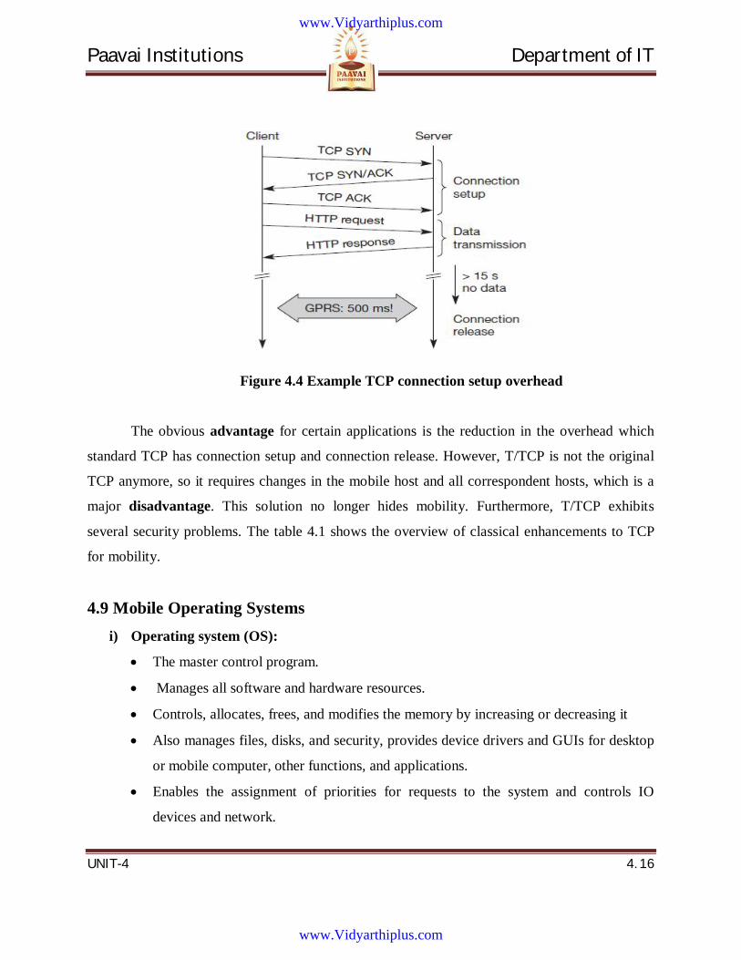
Paavai Institutions Department of IT
UNIT-4 4. 16
Figure 4.4 Example TCP connection setup overhead
The obvious advantage for certain applications is the reduction in the overhead which
standard TCP has connection setup and connection release. However, T/TCP is not the original
TCP anymore, so it requires changes in the mobile host and all correspondent hosts, which is a
major disadvantage. This solution no longer hides mobility. Furthermore, T/TCP exhibits
several security problems. The table 4.1 shows the overview of classical enhancements to TCP
for mobility.
4.9 Mobile Operating Systems i) Operating system (OS):
The master control program.
Manages all software and hardware resources.
Controls, allocates, frees, and modifies the memory by increasing or decreasing it
Also manages files, disks, and security, provides device drivers and GUIs for desktop
or mobile computer, other functions, and applications.
Enables the assignment of priorities for requests to the system and controls IO
devices and network.
www.Vidyarthiplus.com
www.Vidyarthiplus.com
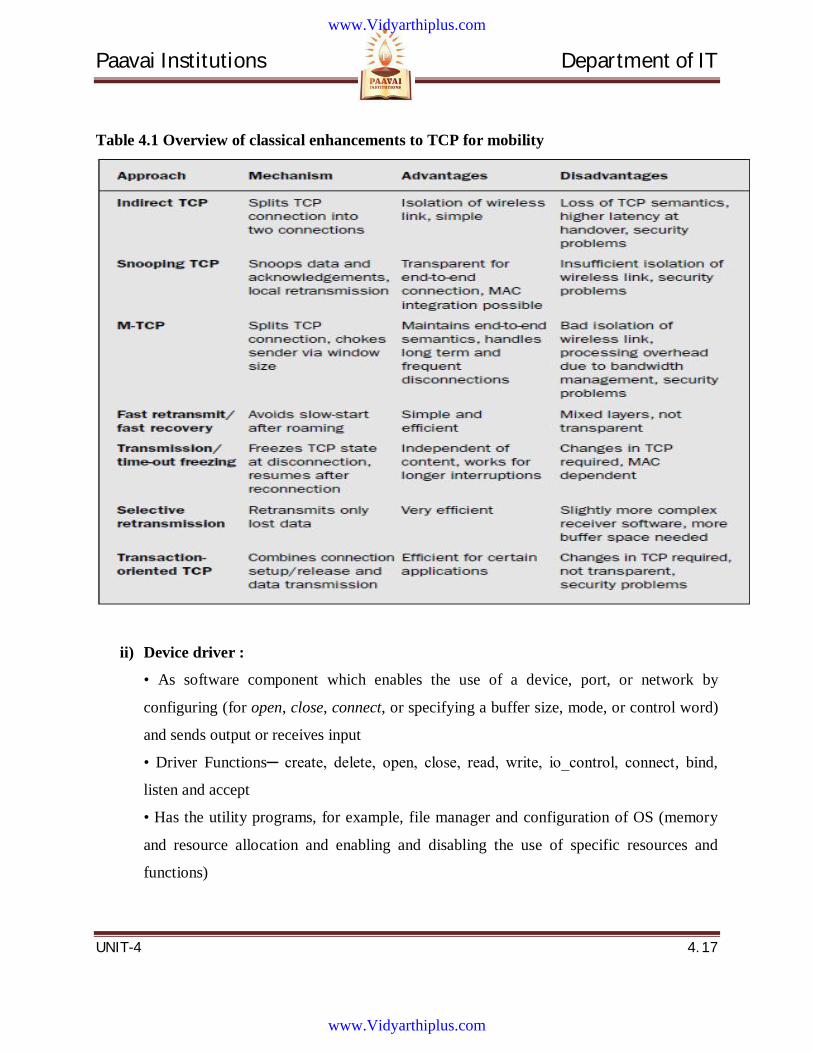
Paavai Institutions Department of IT
UNIT-4 4. 17
Table 4.1 Overview of classical enhancements to TCP for mobility
ii) Device driver :
• As software component which enables the use of a device, port, or network by
configuring (for open, close, connect, or specifying a buffer size, mode, or control word)
and sends output or receives input
• Driver Functions─ create, delete, open, close, read, write, io_control, connect, bind,
listen and accept
• Has the utility programs, for example, file manager and configuration of OS (memory
and resource allocation and enabling and disabling the use of specific resources and
functions)
www.Vidyarthiplus.com
www.Vidyarthiplus.com
Paavai Institutions Department of IT
UNIT-4 4. 18
• Can be accompanied by a specific suite of applications, for example, Internet Explorer
and MS Office
iii) Process:
• A program unit which runs when scheduled to do so by OS and each state of which
is controlled by OS
• Can call a function (method) but cannot call another process directly.
States of a process :
• Can be in any of the states—
1. Created
2. Active
3. Running
4. Suspended
5. Pending for a specified time interval
Pending state of a process for a specific communication from other process
• Signal
• Semaphore
• Mailbox-message
• Queue-message
• Socket
iv) Task:
• An application process which runs according to its schedule set by the OS
• Each state of which is controlled by OS
• Can be a real-time task which has time constraints or maximum defined latency within
which it must run or finish.
v) Thread:
• An application process or a process subunit (when a process or task has multiple
threads)
• Runs as scheduled by the OS
www.Vidyarthiplus.com
www.Vidyarthiplus.com

Paavai Institutions Department of IT
UNIT-4 4. 19
• Each state controlled by OS
• Runs as a light-weight process
Light-weight:
• Does not depend on certain system resources, for example, memory management unit
(MMU), GUI functions provided by the OS, or the functions which need running of other
processes or threads for their implementation.
vi) Interrupt service routine (ISR) :
• A program unit (function, method, or subroutine) which runs when a hardware or
software event occurs.
• Running of which can be masked and can be prioritized by assigning a priority
• Higher priority than any other process or task or thread
vii) Interrupt service thread (IST):
• A special type of ISR or ISR unit (function, method, or subroutine) which initiates and
runs on an event or message from an high priority ISR
• ISTs can be prioritized by assigning a priority
• The type of IST depends on the specific OS
viii) Page :
• A unit of memory which can load from a program stored in a hard drive or from any
other storage device to the program memory, RAM, before the execution of a program
• A contiguous memory address block of 4 kB (in x86 processors), 2 kB, or 1 kB
ix) Page table :
• For address mapping
• Provides the mapping of fragmented physical memory pages with the pages of the
virtual addresses which are the memory addresses
www.Vidyarthiplus.com
www.Vidyarthiplus.com
Paavai Institutions Department of IT
UNIT-4 4. 20
• Pages of memory are spread over the memory-address space leading to fragmentation of
codes and data in physical memory space
x) MMU :
• Creates and maintains the page table and hence performs address mapping and
translation
• Program during execution first translates the accessed address (virtual address) into a
physical address using the page table at the MMU and then accesses the physical address
and fetches the code or data
xi) Priority inversion :
• Takes place when a process or thread which is to provide a waiting object to a higher
priority process or thread gets preempted by a middle priority process or thread and thus
the middle priority process or thread starts running on obtaining the object for which it
was waiting and higher priority process or thread keeps waiting for wait object.
xii) Pipe :
• A virtual device which sends the bytes from a thread to another thread.
Hardware events for interrupts
• Time-out of a timer (clock tick)
• Division by zero
• Overflow
• Underflow detection by hardware during computation
• Finishing of DMA (direct memory access by a peripheral) transfer
• Data abort
• External FIQ (fast interrupt request through a pin input)
• External IRQ (interrupt request through a pin input)
• A memory buffer becoming full
www.Vidyarthiplus.com
www.Vidyarthiplus.com
Paavai Institutions Department of IT
UNIT-4 4. 21
• Port, transmitter, receiver, or device buffer─ becoming half filled, buffer with at
least one memory address filled, and buffer becoming empty
• Buffer─ associated with the memory addresses for the LCD, printer, serial or USB port,
keypad, or modem.
Software related events for interrupts
• Exception─ software instruction for interrupt on detection of a certain condition during
computations or error while logging in
• Illegal operation code provided to CPU
4.10 PALM OS • An OS for handheld devices
• Designed for highly efficient running of small productivity programs for devices with a
few application tasks
• Offers high performance due to a special feature that it supports only one process which
controls all computations by the event handlers
PalmOS Features
• Single process (no multi-processing and multi-threading)
• Compiled for a specific set of hardware, performance very finely tuned
• Memory space partitioned into program memory and multiple storage heaps for data
and applications
• A file in format of a database
• IP-based network connectivity and Wi-Fi (in later version only)
• Integration to cellular GSM/CDMA phone
PalmOS
• No multi-processing or multi-tasking
• Simplifies the kernel of the OS─ there is an infinite waiting loop in the only process
that kernel runs
• The loop polls for an event
www.Vidyarthiplus.com
www.Vidyarthiplus.com
Paavai Institutions Department of IT
UNIT-4 4. 22
Polling for events at specific intervals
• Each polled event─ sends interrupt signal
• Handled by an event handler
• Functioning as non-maskable nonprioritized ISR
Example: Polling for the events
• For a request to run an application or sub-application
• For a search program request to process a query
• Notifications (like time-out alarm)
• GUI actions (such as touching or tapping the screen with stylus)
PalmOS Hardware Support
• Compiles for a specific set of hardware, its performance is very finely tuned
• Optimized to support a very specific range of hardware, CPU, controller chips, and
smaller screens of Palm OSbased devices
Display Screen Support
• Generally wide screen
• 160 × 160 pixels
• Optimized layout of desktop programs displayed on screen
• 256 colour touch screen
• Higher resolution support in new versions
PalmOS Memory Support
• 16 MB memory
• 256 MB internal flash (non-volatile ROM)
• 256 MB card consisting of flash memory which the user inserts into the device
PalmOS Memory Space Partitions
• Program memory dynamic heap─ for process stacks and global variables
• Multiple storage heaps─ for data and applications
PalmOS File Format
• Format of a database
• Multiple records
www.Vidyarthiplus.com
www.Vidyarthiplus.com
Paavai Institutions Department of IT
UNIT-4 4. 23
• Information fields about the file.
• Name, attributes, and version of the database for the application
PalmOS Connectivity
• IP-based network connectivity
• WiFi (in later version only)
• Wireless communication protocols
• Integration to cellular GSM/CDMA phone
PalmOS APIs
• Simple APIs compared to Windows CE
• Simple APIs for developing the GUIs ─ buttons, menus, scroll bar, dialogs, forms, and
tables
• Using HTML markup language
PalmOS Desktop and Desktop Programs
• Desktop for Windows and Mac both and other essential software
• SMS, Address, Card-Info, HotSync, To- Do-List, SMS, Security, Date Book/Calendar,
Calc, Welcome, and Clock
PalmOS PIM
• Address book
• Data book for task-to-do and organization
• Memo pad
• SMTP (simple mail transfer protocol) email download
PalmOS PIM
• Offline creation and sending of POP3 (post office protocol 3) email
• Internet browsing functions using Blazer (a browser for handhelds)
• Windows organizer
• PDA (personal digital assistant)
PalmOS Query Development Platform
• Query development support platform Palm query applications (PQA) written using
HTML and ported at Palm device
www.Vidyarthiplus.com
www.Vidyarthiplus.com
Paavai Institutions Department of IT
UNIT-4 4. 24
PalmOS Client side Applications
• GUI development support on C/C++ platform using Palm SDK
• For Java application using J2ME and advanced tools, for example, Metrowerk
CodeWarrior
• Multimedia applications such as playing music (Palm Tungsten)
PalmOS Ports
• Serial and infrared ports for communication with mobile phones and external modems
• Synchroniszing a PC personal area computer using HotSync after resolving the conflicts
in different versions of files during data exchange
Port Protocols
• IrDA or serial device
• System mounted on a cradle
• Connects to computer PCs through IR or serial port
• A cradle is an attachment on which the handheld device can rest near a PC and connects
to the PC via a USB or infrared
Device handling
• Assumed as a new flash drive of a PC
• HotSync facilitates drag and drop of files from device to PC and vice versa
Cards
• MMC (multimedia card)
• SD (secure digital) memory card
• SDIO (secure digital input/output) memory card
Third Party applications support
• Examples are games, travel and flight planner, calculator, graphic drawings, preparing
slide shows.
www.Vidyarthiplus.com
www.Vidyarthiplus.com
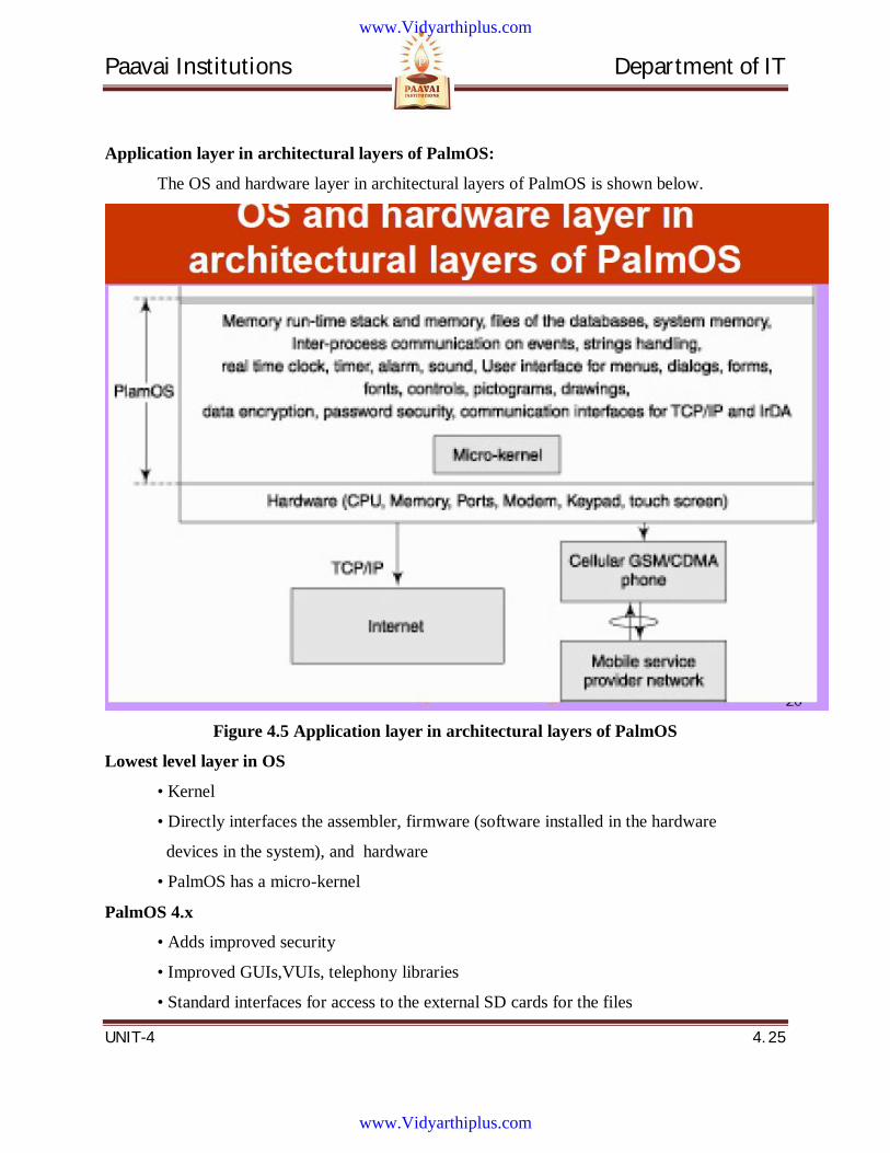
Paavai Institutions Department of IT
UNIT-4 4. 25
Application layer in architectural layers of PalmOS:
The OS and hardware layer in architectural layers of PalmOS is shown below.
Figure 4.5 Application layer in architectural layers of PalmOS
Lowest level layer in OS
• Kernel
• Directly interfaces the assembler, firmware (software installed in the hardware
devices in the system), and hardware
• PalmOS has a micro-kernel
PalmOS 4.x
• Adds improved security
• Improved GUIs,VUIs, telephony libraries
• Standard interfaces for access to the external SD cards for the files
www.Vidyarthiplus.com
www.Vidyarthiplus.com
Paavai Institutions Department of IT
UNIT-4 4. 26
PalmOS 5.x
• Supports
(i) a standardized API for high resolution screen
(ii) dynamic input areas
(iii) Instead of persistent battery-backed RAM, a non-volatile file system using flash
memory─ saves the files and data in case the battery charge is draining out
(iv) ARM, the processor─ providing efficient code and an energy-efficient architecture
Advanced PalmOS Handheld
• Merged PDA and smart phones
• Feature to double as a hard drive using USB cable to PC
• Enables the drag and drop of files between the Palm and PC in a manner similar to the
drag and drop functions in a PC between C: and D: drives
Recent Developments
• Integration in Wndows CE
• A few Windows mobile handheld devices in use are Palm look-alikes
• But these do not deploy PalmOS platform but Windows CE
PalmOS Deficiencies
1. Instead of multi-tasking, PalmOS provides for running a sub-application from within
an application
2. Not an ideal platform for running multimedia applications because due to PalmOS is
not for designing real-time systems
3. Does not offer much expandability
4. Inability to adapt to different sorts of hardware may also be considered a limitation for
this operating system
PalmOS Memory Support
• Assumes that there is a 256 MB memorycard(s)
• The card─ RAM, ROM, and flash memories
• A memory card ─ logical hexadecimal addresses from 00000h to 3FFFFh
www.Vidyarthiplus.com
www.Vidyarthiplus.com
Paavai Institutions Department of IT
UNIT-4 4. 27
PalmOS Memory Support
• RAM─ for stacks of processes and for the global variables in the running processes of
the application(s)
• ROM or flash─ for permanent resident application programs and OS
• Flash─ used for storage of non-volatile data
Memory
• A dynamic heap (within 96 kB for PalmOS 3.x) of application process stacks (3kB)
• TCP/IP stack (32 kB)
• OS functions stack, applications and OS functions dynamic-memory spaces, system
global variables (2.5 kB
• Application global variables
Direct memory address spaces in card
• Used instead of allocated dynamic memory buffers for the I/O port devices (e.g., LCD
display, keypad input, and modem I/Os)
Execute-in-place system
• PalmOS 3.x and 4.x (not 5.x)
• Static allocation of the memory addresses for the application-installed programs and
data storage
File manager
• Manages each file as a database which has multiple records and information fields
• Each record attributes protected record, deleted record (similar to deleted file), locked
ecord (in use by application process or OS), and updated record • Deleted record attribute
helps in data recovery by a recovery program
The info fields of each record
• Record ID and record attributes
• Info fields about the file have (i) name, (ii) file attributes, (iii) version of application
database, (iv) modification number (number of times modified) and access counter for
number of times accessed), and (v) file local ID
www.Vidyarthiplus.com
www.Vidyarthiplus.com
Paavai Institutions Department of IT
UNIT-4 4. 28
File Local ID
• In place of several characters─ requiring several bytes
• The file local ID─ a number used to identify the file locally when an application is
running
File ID
• A local file sorting table uses the file local ID to sort the file in the required order
• For example, the ordering may also be based on the time and date of the last
modification made in the file
Communication APIs
• For serial, IrDA, and TCP/IP communication • Serial communication uses a cradle
Protocols
• Connection management (CM) protocol
• Modem manager (MM)
• Serial link protocol (SLP) interacts with SM to transmit the data to PC
• A device receives the data from the other end through serial manager and SLP, MM, or
CM
Communication Protocols
• MM for deploying a dial up-modem
• CM carries out exchanges for establishing connection, baud rate selection, and finding
version number
• SLP for packet communication on serial line
• A desktop link protocol (DLP) transmits data to PADP when serial device is sending
data to PC and receives data from PADP when serial device is receiving data from the PC
IrDA
• Asynchronous serial (115 kbps)
• Synchronous serial communication (1.152 or 4 Mbps)
• Exchange manager as session layer and IrDA library functions (for IrDA protocol
layers) at lower level
www.Vidyarthiplus.com
www.Vidyarthiplus.com
Paavai Institutions Department of IT
UNIT-4 4. 29
Exchange manager
• Enables data interchange directly without HotSync
• Exchange manager and application use a set of launch codes to generate appropriate
events
Network library functions
• TCP/IP network library functions (for UDP and TCP) to send stack to a net protocol
stack (NPS) and provides a socket API
• Berkeley Socket APIs also supported
• Uses HTTP/HTTPS net library for Internet connectivity
Application Development Method
• Corresponding to each event, there is an event handler
• Application development means defining additional events and coding for the
corresponding handlers
Application Development Method
• An application can be assumed to be divisible into sub-applications am to an−1 along
with the existing event handlers a0 to am−1
• Assume that ai runs on the events ei
• An event ei polled at a sleep interval of ti−1 in an infinite while loop
Application
• SMS
• Address
• Card-Info
• HotSync
• To-Do-List
• Security
• Date Book/Calendar
• Calc, Welcome, and Clock
www.Vidyarthiplus.com
www.Vidyarthiplus.com
Paavai Institutions Department of IT
UNIT-4 4. 30
Application Development Packages
• Supports development packages Palm SDK (software development kit) and CDK
(conduit development kit)
• A conduit is a path
4.11 Windows CE • A 32 bit OS from Microsoft
• Customized for each specific hardware and processor in order to fine-tune the
performance
• Compatible with a variety of processor architectures
• Compiled for a specific set of hardware, its performance is very finely tuned
• User─ personal-computer-like feel and Windows-like GUIs
• Large number of Windows-based applications available at the device
Windows CE 4.x
• Adds improved security, GUIs, VUIs, telephony libraries, and standard interfaces for
access to the external SD cards for the files
Windows CE 5.x
• Supports a non-volatile file system using flash memory
• Flash nowadays used instead of persistent battery-backed RAM
• Windows CE supports a new file system that supports larger file sizes, removable media
encryption, and larger storage media
• The flash file system saves the files and data in case the battery charge is draining out
Windows Embedded CE 6.0
• Open, scalable, 32-bit operating system (OS) with small-footprint and advanced
Windows technologies
• Provides hard real-time capabilities, with a redesigned kernel and embedded specific
development tools
www.Vidyarthiplus.com
www.Vidyarthiplus.com
Paavai Institutions Department of IT
UNIT-4 4. 31
Windows Embedded CE 6.0 devices
• For home as well as work places
• Provisions for media and shared presentations
• Connectivity to cellular networks
Windows Mobile 6 platform
• For mobile devices such as Pocket PC
• for managing Visual C# and Visual Basic .NET codes
• Based on Windows CE and hardware such as personal digital assistants (PDAs) and
smart phones
• Microsoft Visual Studio 2005
• Windows Mobile SDK for creating software for the platform
• The code developed in Visual C++
Thread
• Basic unit of computation
• A process─ any number of threads
• Threads run concurrently
Windows Mobile
• Deployed in (i) Smart phone, (ii) handheld Pocket PC which features the digitizer in the
human computer interface (HCI), and (iii) portable media player • PDA with Microsoft
Smartphone phone device, touch screen, touchpad, or directional pad Pocket PC
• Has digitization software which converts (i) analog signals to digital ones to enable
scanning of photos and video recordings for storage or transmission (ii) audio analog
sources into digital form to enable speech processing, voice, or music for creating records
and files which are stored or transmitted
Windows CE
• Kernel divided into two sub layers
• One sub layer consists of large part of the OS
• Then the OS is adjusted according to the device hardware by adding the remaining part
of the OS
www.Vidyarthiplus.com
www.Vidyarthiplus.com
Paavai Institutions Department of IT
UNIT-4 4. 32
• Second sub layer called hardware abstraction layer
• Shared source licensed with controlled access to full or limited parts of the source code
for a product
• Windows CE 5.x developers have the freedom to modify down to the kernel level
without the need to share their changes with Microsoft or competitors
• A component-based, embedded, real-time operating system with deterministic interrupt
latency
• Can be configured as a real-time operating system for handheld Smart phone, Pocket
PC, computers, and embedded systems
• Modular/componentized to provide the foundation of several classes of devices and
supports addition of features of other components for Windows, DCOM, and COM
• Data format─ database or object file
• File automatically compresses when stored and decompresses when loaded
• Visual C/C++ platform integrates use of web
• .NET XML parsing (trimmed version)
GUIs development support
• Using markup language as well as C/C++ language
• Embedded complex APIs
• Gives the user a PC-like feel and Windows-like GUIs (window resizing not provided)
VUIs development support
• Built-in microphone for voice recording
Display
• High resolution colour/ display
• Touch screen
• Stylus keypad with Windows layout of desktop programs displayed on colored touch
screen
Software
• Desktop for Windows
• Other essential software
www.Vidyarthiplus.com
www.Vidyarthiplus.com
Paavai Institutions Department of IT
UNIT-4 4. 33
• PIM
• Contacts
• Task-to-do
• Smart phone
• Multimedia applications such as playing music
Desktop Programs
• Owner
• Number of messages not read
• Tasks
• Present hour subject
• Button and tool bar for task start menu
• Today calendar, contacts, Internet explorer, messages, phone, pocket MSN, album,
MSN messenger, camera, programs, settings, and help], phone mode indicator (on/off),
signal strength status, speaker status (on/off), and time
Ports
• USB and infrared port support for communication of a device with mobile phones and
for synchronizing a PC using ActiveSync after resolving the conflicts due to different
versions of object files during data exchange.
• Bluetooth
• TCP/IP
• WiFi or Ethernet LAN interface . 30 ActiveSync
• Synchronization of mobile device data with PC using a USB, Bluetooth, and PC
infrared port Connectivity to other devices
• A cradle connects to PC
• USB 2.0 in Windows CE 5.0 PocketPC conform as the USB mass storage class, the
storage on device can be accessed, and drag and drop menu can be used from any USB
port of PC, which considers the handheld device just another flash drive
Window CE device three states
(i) ON with clock frequency lowered in idle state
www.Vidyarthiplus.com
www.Vidyarthiplus.com
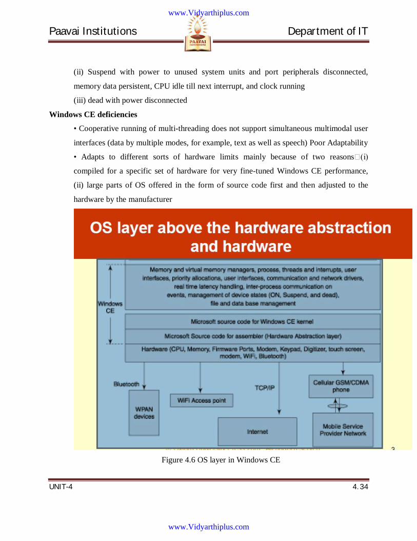
Paavai Institutions Department of IT
UNIT-4 4. 34
(ii) Suspend with power to unused system units and port peripherals disconnected,
memory data persistent, CPU idle till next interrupt, and clock running
(iii) dead with power disconnected
Windows CE deficiencies
• Cooperative running of multi-threading does not support simultaneous multimodal user
interfaces (data by multiple modes, for example, text as well as speech) Poor Adaptability
• Adapts to different sorts of hardware limits mainly because of two reasons (i)
compiled for a specific set of hardware for very fine-tuned Windows CE performance,
(ii) large parts of OS offered in the form of source code first and then adjusted to the
hardware by the manufacturer
Figure 4.6 OS layer in Windows CE
www.Vidyarthiplus.com
www.Vidyarthiplus.com
Paavai Institutions Department of IT
UNIT-4 4. 35
Windows CE Memory Management
• Assumes 4 GB virtual memory
• RAM, ROM, and flash memories
• A memory has logical hexadecimal addresses from 000000000h to FFFFFFFFh
Windows CE Memory Management
• A ROM image─ the footprint of OS, data, and the applications at the permanently
installed ROM (or flash memory)
• An OS configured and customized for an embedded application(s)─ footprint is the
ROM image
• The customization reduces the OS footprint
Windows CE Memory Management
• Windows CE needs a minimum footprint of 350 kB
• Device applications optimized so that the devices need minimal storage below 1 MB
with no disk storage
• Windows CE footprint burned in ROM and configured as it does not allow end-user
extension
Memory manager
• Assigns contagious pages in virtual address space to one of the 32 memory slots
• Each slot of 32 MB
• Allocates a distinct slot to a distinct process among the maximum 32 concurrently
running processes
Memory manager
• Allocation of memory slots reduces fragmentation of pages to a significant extent as
pages of processes are at the contagious addresses in the slot. Fragmentation occurs only
when the memory needed by the process code and data is more than 32 MB
Dynamic heap in the program memory
• The Application process stacks, TCP/IP stack, OS functions stack, applications and OS
functions dynamic-memory spaces, system and application global variables, Bluetooth
stack, and WiFi stack
www.Vidyarthiplus.com
www.Vidyarthiplus.com
Paavai Institutions Department of IT
UNIT-4 4. 36
ROM and RAM
• OS and system functions in ROM
• An automotive PC with Windows CE 8 MB ROM and RAM each
• The Pocket PC 2–8 MB ROM and 8–32 MB RAM in storage memory
File manager
• Manages data as a database or object file
• A file system─ a root directory with which the file folders associate in a tree-like
structure
• Division of all files and folders into volumes
• A volume ─ unit which can be loaded from the device to the computer or can be stored
on the device from the computer
File Volume
• Each volume has a root directory which has directories and file folders • Each directory
can have further divisions into subdirectories and file folders
• Each subdirectory can have further divisions into files and subdirectories till the leaf
node which has a single file folder
Communication, Network, Device, and Peripheral Drivers
• Communication and network APIs for serial, IrDA, TCP/IP, Bluetooth stack, and WiFi
stack
• IP-based connectivity to the network and WiFi-based connectivity in later versions
• Window CE integrates Microsoft Smart phone software
• Enables the application of Windows CE device as cellular GSM/CDMA phone
Serial communication
• Uses a cradle
• A serial manager (SM) provides interface to the device on cradle with the RS232C
COM port of the PC
• Connection management (CM) by using the serial link interface protocol (SLIP) and
point to- point (PPP) protocol
www.Vidyarthiplus.com
www.Vidyarthiplus.com
Paavai Institutions Department of IT
UNIT-4 4. 37
• IrDA asynchronous serial (115 kbps) or synchronous serial communication (1.152 or 4
Mbps) uses ActiveSync
Network connectivity
• By radio transceiver and LAN adapter
• A NDIS (network driver interface specification) used for the drivers other than the
driver loaded at the hardware
Windows CE device drivers
• Device driver and peripheral driver functions for low-level drivers at the kernel
Windows CE
• USB connectivity provided for the peripherals
Event
• Sends interrupt signal which is checked for source, that is, whether the source is a
hardware event, software exception, user action- based event, or kernel event (e.g., a
kernel command, WM_HIBERNATE)
Event handler
• Separate for each event • Asynchronous events
• Event handler calls interrupt service thread (IST) in Windows CE device
Application Development tools
• Visual basic and Visual C++
• Platform Builder─ for developing a Windows CE application by carrying out OS image
creation and integration
• Platform Builder provides an integrated environment for customized operating system
designs based on Windows CE
4.12 SYMBION OS • OS for handheld Smart phones and mobile handhelds with phone and multi-modal
communication features
• Multi-modal means usage of different modes—text, image, video, or audio
• Multi-modal communication integrates and
www.Vidyarthiplus.com
www.Vidyarthiplus.com
Paavai Institutions Department of IT
UNIT-4 4. 38
Synchronizes multimedia (Video with text, audio with text …)
Symbian OS─ C/C++ as well as Java Support
• Supports application development in C/C++ as well as Java and many communication
protocols
• Java Phone
Symbian application architecture
• GUIs and VUIs─ APIs for the buttons, menus, advanced voice features such as a hands-
free speakerphone, and conference calling capability
• Application view
• Application engine
• Powerful development platforms and GUIs
Application development tools
• Personal Java and Symbian Everywhere
• Symbian C++ Software development kit (SDK)
• Symbian emulator for application development using Windows Metrowerk,
CodeWarrior
Synchronization
• SyncML synchronization
• Can also deploy C/C++-based synchronization software
Symbian OS
• Low boot time
• OS supports multi-processing or multitasking
• Multithreading
• Internet connectivity for Web browsing, IP-based network connectivity, and WiFi (in
later version only).
• Integration to cellular GSM/CDMA phone
Memory Support
• Large storage memory
• Includes 80 MB of built-in memory in a Multimedia Card (MMC)
www.Vidyarthiplus.com
www.Vidyarthiplus.com
Paavai Institutions Department of IT
UNIT-4 4. 39
• MMC (multimedia card), SD (secure digital) memory card, and SDIO (secure digital
input/output) memory card.
Software
• Desktop both for Lotus and Windows programs
• Push-to-talk
• Graphics support including support for 3D rendering
• Simple APIs as compared to Windows CE, PIM, Java Phone
• Telephony standard interfaces
• MIDP (mobile information device profile)
• Contacts
• SyncML
• Office
• address book
• Spreadsheet
• Calendar
• Agenda
• Word processor
• Text-to-speech converter
• Browsing
• Messaging (SMS, MMS, email, and IMAP4)
• WAP push Microsoft Office formats (MS Office 97 onwards)
• Slide shows
• email download, offline creation and sending of POP3 (post office protocol 3) email
• Internet browsing
• GUI development support on C/C++ and Java platform
• Java application using J2ME
• multimedia applications such as playing music (Palm Tungsten)
• Wireless communications Support for WLAN
• Adobe Reader for accessing PDF files
www.Vidyarthiplus.com
www.Vidyarthiplus.com
Paavai Institutions Department of IT
UNIT-4 4. 40
• Symantec Client Security 3.0
• IBM Web Sphere Everyplace Access
• BlackBerry Connect
• Oracle Collaboration Suite
• Secure mobile connections via VPN Client
Ports
• Serial
• USB
• Infrared
• Telephony
• Bluetooth for communication with mobile phones and external modems
Third Party Support
• Extensive
• Games
• Travel and flight planner
• Enterprise solutions
• Calculator
• Graphic drawings
• Preparing slide shows
OS and Hardware layers of Symbian
The OS and Hardware layers of Symbian OS is shown in the below figure.
www.Vidyarthiplus.com
www.Vidyarthiplus.com
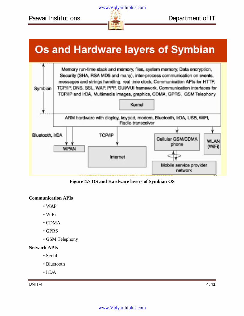
Paavai Institutions Department of IT
UNIT-4 4. 41
Figure 4.7 OS and Hardware layers of Symbian OS
Communication APIs
• WAP
• WiFi
• CDMA
• GPRS
• GSM Telephony
Network APIs
• Serial
• Bluetooth
• IrDA
www.Vidyarthiplus.com
www.Vidyarthiplus.com
Paavai Institutions Department of IT
UNIT-4 4. 42
• TCP/IP, communication APIs for HTTP, TCP/IP, DNS, SSL, WAP, PPP
4.13 LINUX FOR MOBILE DEVICES Linux
• Embedded Linux Consortium (ELC) standards for Linux for designing user interfaces,
managing power consumption in devices, and real-time operation
• Also considered to be more secure than most other operating system. Several
international mobile phone manufacturers use Linux for their OS requirements.
Example of Linux OS – Mobile
• An open source OS
• Enables the user to customize their device to suit their specific needs
• Provides ease to suit different sorts of hardware and software applications
www.Vidyarthiplus.com
www.Vidyarthiplus.com

Paavai Institutions Department of IT
UNIT-4 4. 43
4.14 Question Bank PART – A (2 MARKS)
1. What is slow start?
2. What is the use of congestion threshold?
3. What led to the development of Indirect TCP?
4. What is the goal of M-TCP?
5. What do you mean by persistent mode?
6. What are the characteristics of 2.5G/3.5G wireless networks?
7. What are the configuration parameters to adapt TCP to wireless environments?
8. What are the requirements of mobile IP?
9. Mention the different entities in a mobile IP.
10. Define Mobile node
11. Define Cellular IP
12. What do you mean by mobility binding?
13. Define COA.
14. Define a tunnel.
15. What is encapsulation?
16. What is decapsulation?
17. Define an outer header
18. Define an inner header
19. What is the use of network address translation?
20. Define triangular routing.
www.Vidyarthiplus.com
www.Vidyarthiplus.com
Paavai Institutions Department of IT
UNIT-4 4. 44
PART – B (16 MARKS)
1. Explain traditional TCP in details.
2. Explain classical TCP improvements and snooping TCP.
3. Explain the function of the components of the WAP architecture.
4. Explain the concept of wireless markup language.
5. Explain wireless application protocols with its version WAP 2.0 in detail.
6. Describe the operation of the window flow control mechanism.
7. Explain in detail about tunneling
8. Explain in detail about Cellular IP.
9. Explain in detail about binding concept.
www.Vidyarthiplus.com
www.Vidyarthiplus.com
Paavai Institutions Department of IT
UNIT-5 5. 1
UNIT 5
MOBILE MIDDLEWARE
www.Vidyarthiplus.com
www.Vidyarthiplus.com
Paavai Institutions Department of IT
UNIT-5 5. 2
CONTENTS
5.1 Mobile Middleware
5.2 Middleware for application development
5.3 Adaptation
5.4 Mobile Agent
5.4.1 Reputation and Trust
5.4.2 Differences between trust and reputation systems
5.5 Service discovery
5.6 Services
5.7 Garbage Collection
5.8 Eventing
5.9 Security
5.10 Interoperability
5.11 Adhoc and Sensor Networks
5.11.1 Mobile Sensor Networks Overview
5.11.2 Mobile Ad-Hoc Networks – MANET Overview
5.12 Properties of MANETs
5.13Unique features of sensor networks
5.14Applications
5.15 Challenges
5.16 Constrained Resources
5.17 Security
5.18 Mobility
5.19 Protocols
5.20 Auto Configuration
5.21 Energy Efficient Communication
5.22 Mobility requirements
5.23 Question Bank
www.Vidyarthiplus.com
www.Vidyarthiplus.com
Paavai Institutions Department of IT
UNIT-5 5. 3
TECHNICAL TERMS
1. Mobile middleware is, as the name implies, middleware used in the context of mobile-
computing devices. Mobile middleware offers various transparencies that hide the
complexities of mobile environments.
2. Middleware is the "glue" between software components or between software and the
network or it is the slash in Client/Server.
3. Adaptation middleware assists applications in providing the best quality of service
possible to users, given the widely fluctuating resource levels that may exist in mobile
environments.
4. Mobile agents provide an alternative to static client/server systems for designing
interesting mobile applications that access remote data and computational services.
5. Service discovery is an adaptable middleware in a device (or a mobile computing
system) that dynamically discovers services. Bluetooth Service discovery protocol, JINI,
SLP (service location protocol), UPnP (Universal Plug and Play) service discovery
functions
6. Location management enables the wireless network to discover the current point of
attachment of the MS and deliver calls.
7. Split multipath routing (SMR) is an on-demand routing protocol that constructs
maximally disjoint paths between a given source destination.
8. Caching and multipath routing protocol (CHAMP) makes use of temporal locality in
dropped packets and targets at reducing packet loss due to a route breakdown.
9. Neighbor-table-based multipath routing (NTBMR) is a mixed multipath routing
protocol that deals with regular topology changes in mobile ad hoc networks.
10. Adhoc on-demand distance vector–backing routing (AODV–BR) is a multipath
routing protocol which constructs routes on demand and uses alternate paths only when
the primary route is disrupted.
www.Vidyarthiplus.com
www.Vidyarthiplus.com
Paavai Institutions Department of IT
UNIT-5 5. 4
11. On-demand multipath routing is an extension of the DSR protocol. It exploits
multipath techniques in reducing the frequency of query floods used to discover new
routes.
12. Interoperability is the ability of software and hardware on different machines from
different vendors to share data.
13. A router is a device in computer networking that forwards data packets to their
destinations, based on their addresses. The work a router does it called routing, which is
somewhat like switching, but a router is different from a switch. The latter is simply a
device to connect machines to form a LAN.
14. Routing: In internetworking, the process of moving a packet of data from source to
destination. Routing is usually performed by a dedicated device called a router.
www.Vidyarthiplus.com
www.Vidyarthiplus.com
Paavai Institutions Department of IT
UNIT-5 5. 5
5. MOBILE MIDDLEWARE
5.1 Mobile Middleware Mobile middleware is, as the name implies, middleware used in the context of mobile-
computing devices. Mobile middleware offers various transparencies that hide the complexities
of mobile environments. For instance, location transparency allows applications to exchange data
with other applications without any regard for their location. Similar abstractions are likewise
provided by transparencies on the transport protocol, operating system, programming and others.
Mobile middleware typically involves services like messaging and Remote Procedure Call
(RPC), resource discovery, transactions, directory, security, and storage services and data
synchronization.
5.2 Middleware for application development There are two types of middleware, adaptation middleware and mobile agent systems.
Adaptation middleware assists applications in providing the best quality of service possible to
users, given the widely fluctuating resource levels that may exist in mobile environments.
Mobile agents provide an alternative to static client/server systems for designing interesting
mobile applications that access remote data and computational services.
5.3 Adaptation Mobile computers must execute user- and system-level applications subject to a variety
of resource constraints that generally can be ignored in modern desktop environments. The most
important of these constraints are power, volatile and nonvolatile memory, and network
bandwidth, although other physical limitations such as screen resolution are also important.
www.Vidyarthiplus.com
www.Vidyarthiplus.com
Paavai Institutions Department of IT
UNIT-5 5. 6
In order to provide users with a reasonable computing environment, which approaches
the best that currently available resources will allow, applications and/or system software must
adapt to limited or fluctuating resource levels.
For example, given a sudden severe constraint on available bandwidth, a mobile audio
application might stop delivering a high-bit-rate audio stream and substitute a lower-quality
stream. The user is likely to object less to the lower quality delivery than to the significant
dropouts and stuttering if the application attempted to continue delivering the high-quality
stream.
Similarly, a video application might adjust dynamically to fluctuations in bandwidth,
switching from high-quality, high-frame-rate color video to black-and-white video to color still
images to black-and-white still images as appropriate. A third example is a mobile videogame
application adjusting to decreased battery levels by modifying resolution or disabling three-
dimensional (3D) features to conserve power.
5.4 Mobile Agent (MA) Mobile Agent, namely, is a type of software agent, with the feature of autonomy, social
ability, learning, and most importantly, mobility. A mobile agent is a process that can transport
its state from one environment to another, with its data intact, and be capable of performing
appropriately in the new environment.
Mobile agents decide when and where to move. Movement is often evolved
from RPC methods. Just as a user directs an Internet browser to "visit" a website (the browser
merely downloads a copy of the site or one version of it in the case of dynamic web sites),
similarly, a mobile agent accomplishes a move through data duplication. When a mobile agent
decides to move, it saves its own state, transports this saved state to the new host, and resumes
execution from the saved state.
A mobile agent is a specific form of mobile code, within the field of code mobility.
However, in contrast to the remote evaluation and code on demand programming paradigms,
mobile agents are active in that they can choose to migrate between computers at any time during
www.Vidyarthiplus.com
www.Vidyarthiplus.com
Paavai Institutions Department of IT
UNIT-5 5. 7
their execution. This makes them a powerful tool for implementing distributed applications in
a computer network.
An open multi-agent system (MAS) is a system in which agents that are owned by a
variety of stakeholders continuously enter and leave the system.
5.4.1 Reputation and Trust
The following are general concerns about Trust and Reputation in MA research:
1. Source of trust information is direct experience, witness information, role-based rules.
2. How trust value is calculated
3. Overall trust value
5.4.2 Differences between trust and reputation systems
Trust systems produce a score that reflect the relying party’s subjective view of an
entity’s trustworthiness, whereas reputation systems produce an entity’s (public) reputation score
as seen by the whole community.
Some advantages which mobile agents have over conventional agents:
Computation bundles - converts computational client/server round trips to
relocatable data bundles, reducing network load.
Parallel processing -asynchronous execution on multiple heterogeneous network
hosts
Dynamic adaptation - actions are dependent on the state of the host environment
Tolerant to network faults - able to operate without an active connection between
client and server
Flexible maintenance - to change an agent's actions, only the source (rather than
the computation hosts) must be updated
One particular advantage for remote deployment of software includes increased
portability thereby making system requirements less influential.
5.5 Service Discovery Middleware
www.Vidyarthiplus.com
www.Vidyarthiplus.com
Paavai Institutions Department of IT
UNIT-5 5. 8
The Service discovery middleware is an adaptable middleware in a device (or a mobile
computing system) that dynamically discovers services. Bluetooth Service discovery protocol,
JINI, SLP (service location protocol), UPnP (Universal Plug and Play) are the service discovery
functions
Steps for Service discovery
1. Lets nearby service network (or device or system) recognize that device
2. Lets the nearby network know of device service(s)
3. Searches and discovers a new service(s) at the network
4. Interacting with nearby network using discovered service(s)
5.6 Services The Services that offer by middleware are
Client/Server Connectivity -Middleware provides the mechanism by which network
applications communicate across the network. This includes in the case of database networking
for example the service of putting packages of query results data into network transport packets.
Microsoft SQL Server, for example, uses Sybase's Tabular Data Stream (TDS) protocol to
handle formatting of data for transport across the network. This session layer interaction may
also have its own timers and even error control to handle automatic retransmission of lost
packets. One feature common is the ability for the client to interrupt the current operation on the
server to cancel a large query response download.
Platform Transparency -Client and server don't have to have intimate knowledge of
each other in order for work to get done. Differences between platform specific encodings like
big-endian and little-endian or EBCDIC and ASCII are typically hidden by middleware.
Middleware often runs on a variety of platforms, letting the organization utilize all its existing
desktop and server hardware as applications require. Still, some middleware products find it hard
to look beyond Windows clients and UNIX or Windows NT servers. Make sure the middleware
you're buying handles all the platforms you really have deployed. Microsoft SQL Server DB-
Library middleware provides access only to Windows NT servers (since that's the only supported
www.Vidyarthiplus.com
www.Vidyarthiplus.com
Paavai Institutions Department of IT
UNIT-5 5. 9
SQL Server host platform), but does so from DOS, Windows (3.1, 95, NT), Mac and UNIX
clients.
Network Transparency and Isolation -Middleware often makes networking choices
transparent to application programmers. Actually, though, every middleware product we've ever
heard of runs on TCP/IP, with all the other protocols coming in a distant second. If you want to
be more prepared to run tomorrow's middleware, get on the TCP/IP bandwagon. Then again,
don't let application programmers become too divorced from networking decisions.
SQL Server supports multiple protocols between clients and servers, though some are specific to
a given platform. From Macs, the choices are TCP/IP and AppleTalk. From PCs, there are more
choices: TCP/IP, NetWare IPX/SPX, and NetBIOS/NetBEUI (Named Pipes). In some cases, the
client and server don't even have to run the same network protocol between them. An
intermediate device which might best be called a database relay can get the two end nodes
talking to each other.
Application and Tool Support (APIs) -Before middleware can be used, it must present
its own API to client applications that might use it. For shrink-wrapped tools like a database
query tool, the API support can be critical. While ODBC has provided some level of
transparency across multiple proprietary database APIs, many RDBMS vendors still encourage
using their own proprietary APIs. Be sure you know what APIs your middleware offers as well
as what APIs your tools can use. Hopefully there's a match! SQL Server offers both ODBC
standard and DB-Library proprietary APIs on the client. For more generic middleware, the API
on the server must be available as well; for RDBMS middleware, the server side is typically
hard-coded to support an RDBMS.
Language Support -Middleware often provides transparency across different SQL
database dialects. Even when coding in embedded SQL in a 3GL, the middleware might allow
the use of a single SQL dialect across a variety of RDBMS back ends. Outside of the database
specific middleware products, generic middleware products often allow different programming
languages to be used to create the distinct pieces of an application (pieces that reside on different
machines). Since SQL Server's DB-Library only supports SQL Server RDBMSs, the SQL dialect
supported is Transact SQL, a superset of ANSI 89 SQL created by Sybase and Microsoft.
www.Vidyarthiplus.com
www.Vidyarthiplus.com
Paavai Institutions Department of IT
UNIT-5 5. 10
RDBMS Support -When we focus on database networking middleware (also called data
access middleware), middleware may also provide a level of transparency across different data
storage formats. It will make different RDBMSs look like the same RDBMS. ODBC is one way
of hiding RDBMS differences, but middleware products often provide multiple RDBMS support
from both proprietary and standard APIs. SQL Server's DB-Library middleware does support
ODBC interfaces, but still natively gets users to SQL Server RDBMS only.
Much database networking middleware is closely tied to the RDBMS of that same
vendor. To get to even more data sources, database gateway products are needed. Third party
products like TechGnosis SequeLink or IBI EDA/SQL offer more variety in RDBMSs. Even
Microsoft has recently allied with IBI to have their multi-RDBMS connectivity solution
connected to the DB-Library network so that DB-Library clients can get to RDBMSs other than
SQL Server.
For non-data access products, RDBMS functionality can still be provided using
extensions to make accessing that kind of data directly easy over the middleware solution
deployed. NetWeave is one messaging vendor that also has database access software options.
5.7 Garbage collection:
Garbage collection is the systematic recovery of pooled computer storage that is being
used by a program when that program no longer needs the storage. This frees the storage for use
by other programs (or processes within a program). It also ensures that a program using
increasing amounts of pooled storage does not reach its quota (in which case it may no longer be
able to function).
Garbage collection is an automatic memory management feature in many modern
programming languages, such as Java and languages in the .NET framework. Languages that use
garbage collection are often interpreted or run within a virtual machine like the JVM. In each
case, the environment that runs the code is also responsible for garbage collection.
www.Vidyarthiplus.com
www.Vidyarthiplus.com
Paavai Institutions Department of IT
UNIT-5 5. 11
In older programming languages, such as C and C++, allocating and freeing memory is
done manually by the programmer. Memory for any data that can't be stored within a primitive
data type, including objects, buffers and strings, is usually reserved on the heap. When the
program no longer needs the data, the programmer frees that chunk of data with an API call.
Because this process is manually controlled, human error can introduce bugs in the code.
Memory leaks occurs when the programmer forgets to free up memory after the program no
longer needs it. Other times, a programmer may try to access a chunk of memory that has already
been freed, leading to dangling pointers that can cause serious bugs or even crashes.
Programs with an automatic garbage collector (GC) try to eliminate these bugs by
automatically detecting when a piece of data is no longer needed. A GC has two goals: any
unused memory should be freed, and no memory should be freed unless the program will not use
it anymore. Although some languages allow memory to be manually freed as well, many do not.
5.8 Eventing In event notification, a UPnP device notifies control points that registered a service in
control phase of changes to the services they registered to, following a publish-subscribe –style
messaging paradigm.
Universal Plug and Play, UPnP, provides a programming language and platform
independent discovery mechanism by relying on HTTP and XML. UPnP relies on listening and
responding to HTTP-based requests on a particular multicast channel. UPnP architecture consists
of control points (i.e. UPnP client devices) and UPnP devices. UPnP can be seen to contain five
phases: discovery, description, control, event notification and presentation.
5.9 Security
Just as any other platform that executes general-purpose applications; mobile platforms
need security mechanisms to protect the resources on the devices. Two important techniques can
be distinguished: memory management and software protection. Native platforms need to ensure
www.Vidyarthiplus.com
www.Vidyarthiplus.com
Paavai Institutions Department of IT
UNIT-5 5. 12
that applications cannot access memory that belongs to other applications or to the platform
itself. This separation is guaranteed by memory management. Some of the older mobile device
platforms such as Palm OS have no form of memory protection at all, which makes these
platforms inherently in secure.
Most modern native platforms (Windows Mobile, Symbian) do provide basic memory
protection. One of the important strengths of managed platforms (.NET Compact Framework,
Java ME) is that they have a strong memory protection model because applications have no
direct access to the memory and because these platforms guarantee type safety. Other resources
on the device such as personal data, wireless networking, or SMS messages are accessed via
APIs and are protected by the security architecture of the platform.
Security Issues
Important security mechanisms found on full-scaled platforms are omitted
The developer has very little options in customizing security mechanisms
APIs can be protected but often in an all-or-nothing way
It is hard to securely store sensitive data
A mobile device is subject to different kinds of threats
5.10 Interoperability
Interoperability is the ability of software and hardware on different machine from
different vendors to share data.
The need for interoperability between information systems is readily apparent in
peacekeeping and disaster-response operations. In these situations, a coalition of civilian and
military organizations, each with its own intelligence or other information assets, is formed on
short notice and required to operate in areas where the fixed communication infrastructure has
been severely damaged or completely destroyed. The field units are forced to rely on limited-
power devices that use an unreliable low-bandwidth data link to communicate between them and
to access information held within constituent organizations’ headquarters.
www.Vidyarthiplus.com
www.Vidyarthiplus.com
Paavai Institutions Department of IT
UNIT-5 5. 13
5.11 Adhoc and Sensor Networks 5.11.1 Mobile Sensor Networks Overview
As sensors become widely deployed, some sensors may be enhanced with mobility. Such
mobile sensors may be more powerful and can re-charge themselves automatically. An important
application is in the robot area.
Need of mobile sensors:
Resilient to failures
Reactive to events
To support disparate missions
5.11.2Mobile Ad-Hoc Networks – MANET Overview
Mobile Ad hoc NETworks (MANETs) are wireless networks which are characterized by
dynamic topologies and no fixed infrastructure. Each node in a MANET is a computer that may
be required to act as both a host and a router and, as much, may be required to forward packets
between nodes which cannot directly communicate with one another. Each MANET node has
much smaller frequency spectrum requirements that that for a node in a fixed infrastructure
network.
A MANET is an autonomous collection of mobile users that communicate over relatively
bandwidth constrained wireless links. Since the nodes are mobile, the network topology may
change rapidly and unpredictably over time. The network is decentralized, where all network
activity including discovering the topology and delivering messages must be executed by the
nodes themselves, i.e., routing functionality will be incorporated into mobile nodes.
www.Vidyarthiplus.com
www.Vidyarthiplus.com
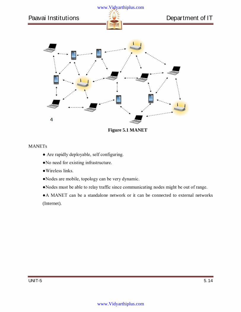
Paavai Institutions Department of IT
UNIT-5 5. 14
Figure 5.1 MANET
MANETs
● Are rapidly deployable, self configuring.
●No need for existing infrastructure.
●Wireless links.
●Nodes are mobile, topology can be very dynamic.
●Nodes must be able to relay traffic since communicating nodes might be out of range.
●A MANET can be a standalone network or it can be connected to external networks
(Internet).
www.Vidyarthiplus.com
www.Vidyarthiplus.com

Paavai Institutions Department of IT
UNIT-5 5. 15
Figure 5.2 Example of a MANET
MANET usage areas
●Military scenarios
●Sensor networks
●Rescue operations
●Students on campus
●Free Internet connection sharing
●Conferences
Mechanisms required in a MANET
●Multi-hop operation requires a routing mechanism designed for mobile nodes.
●Internet access mechanisms.
●Self configuring networks requires an address allocation mechanism.
●Mechanism to detect and act on, merging of existing networks.
●Security mechanisms.
5.12 Properties of MANETs
www.Vidyarthiplus.com
www.Vidyarthiplus.com
Paavai Institutions Department of IT
UNIT-5 5. 16
MANET enables fast establishment of networks. When a new network is to be
established, the only requirement is to provide a new set of nodes with limited wireless
communication range. A node has limited capability, that is, it can connect only to the
nodes which are nearby. Hence it consumes limited power.
A MANET node has the ability to discover a neighboring node and service. Using a
service discovery protocol, a node discovers the service of a nearby node and
communicates to a remote node in the MANET.
MANET nodes have peer-to-peer connectivity among themselves.
MANET nodes have independent computational, switching (or routing), and
communication capabilities.
The wireless connectivity range in MANETs includes only nearest node connectivity.
The failure of an intermediate node results in greater latency in communicating with the
remote server.
Limited bandwidth available between two intermediate nodes becomes a constraint for
the MANET. The node may have limited power and thus computations need to be
energy-efficient.
There is no access-point requirement in MANET. Only selected access points are
provided for connection to other networks or other MANETs.
MANET nodes can be the iPods, Palm handheld computers, Smart phones, PCs, smart
labels, smart sensors, and automobile-embedded systems
MANET nodes can use different protocols, for example, IrDA, Bluetooth, ZigBee,
802.11, GSM, and TCP/IP.MANET node performs data caching, saving, and
aggregation.
MANET mobile device nodes interact seamlessly when they move with the nearby
wireless nodes, sensor nodes, and embedded devices in automobiles so that the seamless
connectivity is maintained between the devices.
5.13 Unique features of sensor networks
www.Vidyarthiplus.com
www.Vidyarthiplus.com
Paavai Institutions Department of IT
UNIT-5 5. 17
Dynamic network topology
Bandwidth constraints and variable link capacity
Energy constrained nodes
Multi-hop communications
Limited security
Autonomous terminal
Distributed operation
Light-weight terminals
5.14 Applications The set of applications for MANETs is diverse, ranging from small, static
networks that are constrained by power sources, to large-scale, mobile, highly dynamic
networks. The design of network protocols for these networks is a complex issue. Regardless of
the application, MANETs need efficient distributed algorithms to determine network
organization, link scheduling, and routing. Some of the main application areas of MANET’s are:
Military battlefield– soldiers, tanks, planes. Ad- hoc networking would allow the
military to take advantage of commonplace network technology to maintain an
information network between the soldiers, vehicles, and military information
headquarters.
www.Vidyarthiplus.com
www.Vidyarthiplus.com
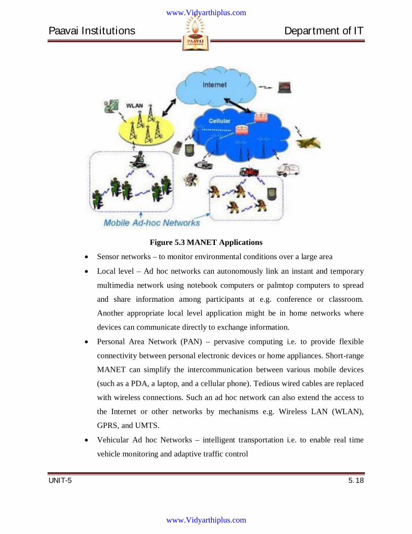
Paavai Institutions Department of IT
UNIT-5 5. 18
Figure 5.3 MANET Applications
Sensor networks – to monitor environmental conditions over a large area
Local level – Ad hoc networks can autonomously link an instant and temporary
multimedia network using notebook computers or palmtop computers to spread
and share information among participants at e.g. conference or classroom.
Another appropriate local level application might be in home networks where
devices can communicate directly to exchange information.
Personal Area Network (PAN) – pervasive computing i.e. to provide flexible
connectivity between personal electronic devices or home appliances. Short-range
MANET can simplify the intercommunication between various mobile devices
(such as a PDA, a laptop, and a cellular phone). Tedious wired cables are replaced
with wireless connections. Such an ad hoc network can also extend the access to
the Internet or other networks by mechanisms e.g. Wireless LAN (WLAN),
GPRS, and UMTS.
Vehicular Ad hoc Networks – intelligent transportation i.e. to enable real time
vehicle monitoring and adaptive traffic control
www.Vidyarthiplus.com
www.Vidyarthiplus.com
Paavai Institutions Department of IT
UNIT-5 5. 19
Civilian environments – taxi cab network, meeting rooms, sports stadiums, boats,
small aircraft
Emergency operations – search and rescue, policing and fire fighting and to
provide connectivity between distant devices where the network infrastructure is
unavailable. Ad hoc can be used in emergency/rescue operations for disaster relief
efforts, e.g. in fire, flood, or earthquake. Emergency rescue operations must take
place where non-existing or damaged communications infrastructure and rapid
deployment of a communication network is needed. Information is relayed from
one rescue team member to another over a small hand held.
5.15 Challenges To design a good wireless ad hoc network, various challenges have to be taken
into account:
Dynamic Topology: Nodes are free to move in an arbitrary fashion resulting in
the topology changing arbitrarily. This characteristic demands dynamic
configuration of the network.
Limited security: Wireless networks are vulnerable to attack. Mobile ad hoc
networks are more vulnerable as by design any node should be able to join or
leave the network at any time. This requires flexibility and higher openness.
Limited Bandwidth: Wireless networks in general are bandwidth limited. In an ad
hoc network, it is all the more so because there is no backbone to handle or
multiplex higher bandwidth
Routing: Routing in a mobile ad hoc network is complex. This depends on many
factors, including finding the routing path, selection of routers, topology, protocol
etc.
www.Vidyarthiplus.com
www.Vidyarthiplus.com
Paavai Institutions Department of IT
UNIT-5 5. 20
5.16 Constrained Resources ●Self starting and self organizing
●Multi-hop, loop-free paths
●Dynamic topology maintenance
●Rapid convergence
●Minimal network traffic overhead
●Scalable to large networks
5.17 Security in MANET’s Securing wireless ad-hoc networks is a highly challenging issue. Understanding possible
form of attacks is always the first step towards developing good security solutions. Security of
communication in MANET is important for secure transmission of information. Absence of any
central co-ordination mechanism and shared wireless medium makes MANET more vulnerable
to digital/cyber attacks than wired network there are a number of attacks that affect MANET.
These attacks can be classified into two types:
External Attack: External attacks are carried out by nodes that do not belong to the
network. It causes congestion sends false routing information or causes unavailability of
services.
Internal Attack: Internal attacks are from compromised nodes that are part of the
network. In an internal attack the malicious node from the network gains unauthorized
access and impersonates as a genuine node. It can analyze traffic between other nodes
and may participate in other network activities.
Denial of Service attack: This attack aims to attack the availability of a node or the
entire network. If the attack is successful the services will not be available. The attacker
generally uses radio signal jamming and the battery exhaustion method.
www.Vidyarthiplus.com
www.Vidyarthiplus.com
Paavai Institutions Department of IT
UNIT-5 5. 21
Impersonation: If the authentication mechanism is not properly implemented a
malicious node can act as a genuine node and monitor the network traffic. It can also
send fake routing packets, and gain access to some confidential information.
Eavesdropping: This is a passive attack. The node simply observes the confidential
information. This information can be later used by the malicious node. The secret
information like location, public key, private key, password etc. can be fetched by
eavesdropper.
Routing Attacks: The malicious node makes routing services a target because it’s an
important service in MANETs. There are two flavors to this routing attack. One is attack
on routing protocol and another is attack on packet forwarding or delivery mechanism.
The first is aimed at blocking the propagation of routing information to a node. The latter
is aimed at disturbing the packet delivery against a predefined path.
Black hole Attack: In this attack, an attacker advertises a zero metric for all destinations
causing all nodes around it to route packets towards it. A malicious node sends fake
routing information, claiming that it has an optimum route and causes other good nodes
to route data packets through the malicious one. A malicious node drops all packets that it
receives instead of normally forwarding those packets. An attacker listen the requests in a
flooding based protocol.
Wormhole Attack: In a wormhole attack, an attacker receives packets at one point in the
network, tunnels them to another point in the network, and then replays them into the
network from that point. Routing can be disrupted when routing control message are
tunneled. This tunnel between two colluding attacks is known as a wormhole.
Replay Attack: An attacker that performs a replay attack is retransmitted the valid data
repeatedly to inject the network routing traffic that has been captured previously. This
attack usually targets the freshness of routes, but can also be used to undermine poorly
designed security solutions.
Jamming: In jamming, attacker initially keep monitoring wireless medium in order to
determine frequency at which destination node is receiving signal from sender. It then
transmit signal on that frequency so that error free receptor is hindered.
www.Vidyarthiplus.com
www.Vidyarthiplus.com
Paavai Institutions Department of IT
UNIT-5 5. 22
Man- in- the- middle attack: An attacker sites between the sender and receiver and
sniffs any information being sent between two nodes. In some cases, attacker may
impersonate the sender to communicate with receiver or impersonate the receiver to reply
to the sender.
Gray-hole attack: This attack is also known as routing misbehavior attack which leads
to dropping of messages. Gray-hole attack has two phases. In the first phase the node
advertise itself as having a valid route to destination while in second phase, nodes drops
intercepted packets with a certain probability.
5.18 Mobility First of all, mobility management has to be taken into consideration while designing the
infrastructure itself for wireless mobile networks. Effective and efficient handoff is the key
factor enabling the mobile user to move seamlessly from one cell to another cell, from one
service area to another, and so on.
Mobility management features two tasks—location management and handoff
management—that enable mobile networks to locate roaming MSs for call delivery and
maintain connections as the MSs are moving around.
Location management enables the wireless network to discover the current point of
attachment of the MS and deliver calls. The first stage of location management is the location
registration (or location update). In this stage, the MS periodically notifies the network of its
new AP, allowing the network to authenticate the user and revise the user’s location profile.
The second stage is the call delivery, in which the wireless mobile network is queried for the
MS location profile and the current position of the MS is found.
Handoff primarily represents a process of changing some of the parameters of a channel
(frequency, time slot, spreading code, or a combination of them) associated with the current
connection in progress. The handoff process usually consists of two phases: the handoff
initialization phase and the handoff-enabling phase. In the handoff initialization phase, the
quality of the current communication channel is monitored in order to decide when to trigger
www.Vidyarthiplus.com
www.Vidyarthiplus.com
Paavai Institutions Department of IT
UNIT-5 5. 23
the handoff process. In the handoff execution phase, the allocation of new resources by a new
BS is initiated and processed. Poorly designed handoff schemes tend to generate very heavy
signaling traffic and thereby result in a dramatic decrease in quality of integrated service in
the wireless network.
Mobility management requests are often initiated either by a MS’s movement when it
crosses a cell boundary, or by a deteriorated quality of signal received on a currently
employed channel. With the anticipated increased penetration of wireless services, the next
generation of wireless mobile networks will provide an architectural basis to support a drastic
increase in traffic bandwidth. According to the IMT-2000 outline of ITU, a simultaneous
operation of high capacity pico cells, urban terrestrial microcells and macro cells, and large
satellite cells will be exploited in IMT-2000. Much more frequent handoffs will occur when
the size of the cell becomes smaller or there is a drastic change in the propagation condition
of the signal.
Mobility management should be given more careful consideration in next-generation
wireless mobile networks. Various handoff initiating criteria have been proposed recently. In
order to decide when to trigger the handoff, the quality of the current communication channel
is monitored. Handoff is a very rigorous process; therefore, unnecessary handoffs should be
avoided. If the handoff criteria are not chosen carefully, the call might be handed back and
forth several times between two neighboring BSs, especially when the MS is moving around
the overlapping region between the coverage area boundaries of the two BSs.
If the criteria are too conservative, then the call may be lost before the handoff can take
place. Based on the link status, the measurement process determines the need for handoff and
the new target cell for transfer. Since the propagation condition between the BS and the MS
is made up of the direct radio propagation paths (direct, reflection, refraction), the following
types of handoff-initiating criteria have been proposed:
Word error indicator: A metric that indicates whether the current burst was
demodulated properly in the MS.
Received signal strength indication: A measure of the received signal strength that
indicates useful dynamic range, typically between 80 and 100 dB.
www.Vidyarthiplus.com
www.Vidyarthiplus.com
Paavai Institutions Department of IT
UNIT-5 5. 24
Quality indicator: An estimate of the “eye opening” for a radio signal, which is related
to the signal to interference and noise ratio, including the effects of dispersion. The
quality indicator has a narrow range (relating to the range of SIR from 5 dB to 25 dB).
In the design of a good handoff scheme, it is desirable that the blocking
probability for calls originated in a cell be minimized as much as possible. However,
from the user’s point of view, how to handle a handoff request is more important. If new
resources cannot be allocated in a timely fashion, the ongoing call has to face forced
termination, which is much more disastrous than the blocking of a new call.
In addition, attempts should be made to decrease the transmission delay of non–
real-time service calls as well as increase channel utilization in a fair manner. Therefore,
the handoff strategy for integrated service in next-generation wireless networks needs to
take different features of these services into account (i.e., the ideal handoff processes
have to be service dependent).
For example, transmission of real-time service is very sensitive to interruptions.
On the other hand, transmission delay of non–real time service does not have any
significant impact on the performance of service (i.e., non–real-time service is delay
insensitive). Therefore, a successful handoff without interruption is very important for
real-time services, but not so critical for non–real time services. In order to provide better
service for a MS with limited frequency spectrum, a wireless system must manage radio
resources efficiently.
5.19 Protocols Hybrid Protocols are
Zone Routing
The zone routing protocol (ZRP) is a hybrid of proactive and reactive protocols. It tries to
limit the scope of proactive search to the node’s local neighborhood. At the same time, global
search throughout the network can also be performed efficiently by querying selected nodes (and
not all the nodes in the network). A node’s local neighborhood is called a routing zone.
Specifically, a node’s routing zone is defined as the set of nodes whose minimum distance in
www.Vidyarthiplus.com
www.Vidyarthiplus.com
Paavai Institutions Department of IT
UNIT-5 5. 25
hops from the node is no greater than the zone radius. A node maintains routes to all the
destinations in the routing zone proactively. It also maintains its zone radius, and the overlap
from the neighboring routing zones.
To construct a routing zone, the node must identify all its neighbors first which are one
hop away and can be reached directly. The process of neighbor discovery is governed by the
neighbor discovery protocol (NDP), a MAC-level scheme. ZRP maintains the routing zones via a
proactive component called the intra-zone routing protocol (IARP) and is implemented as a
modified distance vector scheme. Thus, IARP is responsible for maintaining routes within the
routing zone. Another protocol called the inter-zone routing protocol (IERP) is responsible for
discovering and maintaining the routes to nodes beyond the routing zone. This process uses a
query-response mechanism on-demand basis. IERP is more efficient than standard flooding
schemes.
When a source node has data to be sent to a destination which is not in the routing zone,
the source initiates a route query packet. The latter is uniquely identified by the tuple -<source
node ID, request number>. This request is then broadcast to all the nodes in the source node’s
periphery. When a node receives this query, it adds its own ID to the query. Thus, the sequence
of recorded nodes presents a route from the source to the current routing zone. Otherwise, if the
destination is in the current node’s routing zone, a route reply is sent back to the source along the
reverse path from the accumulated record. A big advantage of this scheme is that a single route-
request can result in multiple route replies. The source can determine the quality of these
multiple routes based on such parameter(s) as hop count or traffic and choose the best route to be
used.
Fisheye State Routing
The fisheye state routing (FSR) protocol uses multilevel fisheye scopes to reduce the
routing update overhead in large networks. The key idea is to exchange link-state entries with the
neighbors with a frequency that depends on the distance to the destination. More effort is made
in collecting topological data that is more likely to be required soon. With the basic assumption
that nearby changes in network topology matter the most, FSR focuses its efforts on viewing the
www.Vidyarthiplus.com
www.Vidyarthiplus.com
Paavai Institutions Department of IT
UNIT-5 5. 26
nearby changes with the highest resolution and very frequently. The changes at distant nodes are
seen with a lower resolution and less frequently.
Landmark Routing (LANMAR) for MANET with Group
Landmark ad hoc routing (LANMAR) combines the features of FSR and landmark
routing. The major addition here is to use landmarks for each set of nodes that move together as
a group (e.g., a company of soldiers in a battlefield). This reduces the overall routing update
overhead. The nodes exchange the link-state information only with their neighbors, as in FSR.
Routes within a fisheye scope are accurate, and the routes to remote groups of nodes called
subnets are “handled” by the corresponding landmarks in the neighborhood. As the packet comes
closer to the destination, it eventually switches to the accurate route provided by the fisheye. A
modified version of FSR is used for routing.
The major difference between the two routing schemes is that in FSR the routing table
contains all the nodes in the network. On the other hand, in LANMAR, the routing table contains
only the nodes within the scope and the landmark nodes. This reduces the routing table size and
overhead of the update traffic and hence increases the scalability of the scheme. While relaying a
packet, the logical subnet for the destination is looked up and the packet is routed toward the
landmark node for that subnet. However, the packet need not pass through the landmark. For the
updates in the routing table, LANMAR uses a scheme similar to that in FSR. Nodes periodically
exchange the topological information with their immediate neighbors. In each update, a node
sends entries within its fisheye scope. A distance vector with information about all the landmark
nodes is also piggybacked onto this update.
Multipath Routing Protocols
Based on the route-discovery mechanism, routing protocols are classified as either
reactive, proactive, or hybrid protocols as discussed in previous sections. Similarly, based on the
number of routes discovered between source and destination, protocols can be either unipath or
multipath protocols. Multipath protocols aim at providing redundant paths to the destination. The
availability of redundant paths to the same destination increases the reliability and robustness of
the network. Providing multiple paths is beneficial, particularly in wireless ad hoc networks
where routes are disconnected frequently due to mobility of the nodes and poor wireless link
www.Vidyarthiplus.com
www.Vidyarthiplus.com
Paavai Institutions Department of IT
UNIT-5 5. 27
quality. However, multipath routing can lead to increased out-of-order delivery and resequencing
of packets at the destination along with increased collision.
Multipath routing protocols can also aid in secure routing against denial-of service
attacks by providing multiple routes between the nodes. Nodes can switch over to an alternate
route when the primary route has intermediate malicious nodes and appears to have been
compromised. Various unipath protocols discussed in earlier sections can discover multiple paths
between nodes. Diversity coding takes advantage of multiple paths for fault-tolerant
communication between nodes, where out of n paths available, m paths are used for transmitting
data and the remaining n − m paths are used for transmitting redundant information.
Multipath Routing protocol:
On-Demand Multipath Routing for Mobile Ad Hoc Networks
On-demand multipath routing is an extension of the DSR protocol. It exploits multipath
techniques in reducing the frequency of query floods used to discover new routes. It also
improves performance by providing all intermediate nodes in the primary (shortest) route with
alternate paths rather than providing only the source with alternate paths. Two multipath
extensions for DSR (MDSR) have been proposed; in both, DSR starts route discovery by
flooding the network using query messages. Each query message carries the sequence of hops it
passed through in the message header. After receiving a query packet, the destination node
replies with a reply packet that simply copies the route from the query packet and sends it back.
Each node maintains a route cache, where complete routes to desired destinations are
stored as learned from the reply packets. The destination node can receive many copies of the
flooded query messages. In the first MDSR, the destination replies to a set of query packets that
carry a source route that is link-wise disjoint from the primary source route. The primary source
route is the route taken by first query reaching the destination node. The source caches all routes
received in reply packets in its local route cache. When the primary route breaks, the remaining
shortest route is used.
The process continues still all the alternate routes are exhausted, and then a fresh route
discovery is initiated. Alternate routes are therefore provided only to the source since reply
www.Vidyarthiplus.com
www.Vidyarthiplus.com
Paavai Institutions Department of IT
UNIT-5 5. 28
packets sent by the destination node are addressed only to the source node. An intermediate link
failure on the primary route results in a rote error packet being sent to the source, which will then
use an alternate route. This leads to retransmissions of data packets already in transit from the
broken link.
To avoid this retransmission’s, in the second MDSR all intermediate nodes are provided a
disjoint alternate route so that in-transit data packets no longer face route loss. The destination
node now replies to each intermediate node in the primary route with an alternate disjoint route
to the destination. It is possible that not all intermediate nodes will get a different disjoint route
(especially in sparse networks), and there still may be temporary route loss due to link failures,
until an upstream node switches to an alternate route.
Thus, any intermediate node with an alternate path to the destination douses the error
packet. This continues till the source gets an error packet and has no alternate route resulting in
initiation of a new route discovery.
Ad Hoc On-Demand Distance Vector-Backup Routing
The adhoc on-demand distance vector–backing routing (AODV–BR) is a multipath
routing protocol which constructs routes on demand and uses alternate paths only when the
primary route is disrupted. This method utilizes a mesh arrangement to provide multiple alternate
paths to existing on-demand routing protocols without extra control message overhead.
Similar to its parent protocol AODV, this protocol also consists of two phases:
Route construction: Source initiates route discovery by flooding a route request
(RREQ) packet having a unique identifier so that intermediate nodes can detect and drop
duplicate packets. Upon receiving a non-duplicate RREQ, the intermediate node stores the
previous hop and the source node information in its route table. This process is also known as
backward learning. It then broadcasts the RREQ packet or sends a route reply (RREP) packet, if
it has a route to the destination. The destination node sends a RREP via the selected route when
it receives the first RREQ packet or subsequent RREQs that have a better route than the
previously replied route.
The mesh construction and the alternate paths are established during the route reply
phase. A node overhearing a RREP packet transmitted by a neighbor (on the primary route) but
www.Vidyarthiplus.com
www.Vidyarthiplus.com
Paavai Institutions Department of IT
UNIT-5 5. 29
not directed to it records that neighbor as the next hop to the destination in its alternate route
table. A node may receive numerous RREPs for the same route if the node is within the radio
range of more than one intermediate node of the primary route. The node then chooses the best
route among them and inserts it into the alternate route table. When the RREP packet reaches the
source, the primary route between the source and the destination is established and ready for use.
Nodes that have an entry to the destination in their alternate route table become part of the mesh
structure.
Split Multipath Routing
Split multipath routing (SMR) is an on-demand routing protocol that constructs
maximally disjoint paths between a given source destination. Multiple routes are established, and
data traffic is split into them to avoid congestion and facilitate efficient use of network resources.
These routes may not be of equal lengths. SMR like other on-demand routing protocols builds
multiple routes using request/reply cycles.
Caching and Multipath Routing Protocol
The caching and multipath routing protocol (CHAMP) makes use of temporal locality in
dropped packets and targets at reducing packet loss due to a route breakdown. Every node
maintains a small buffer for caching data packets that pass through it. When a downstream node
discovers a error in forwarding, an upstream node with the relevant data in its buffer and an
alternate route can retransmit the data. This approach can be useful only if nodes maintain
alternate routes to a destination. The main features of this protocol are therefore shortest
multipath route discovery and cooperative packet caching. Every node maintains a route cache
and a route request cache. A route cache is a list containing forwarding information to every
active destination. Each entry contains the destination identifier, distance to the destination, next
hop nodes to the destination, the last time, and the number of times each successor node was
used for forwarding. A route entry that has not been used for route lifetime is deleted. The route
request cache at a node is a list containing an entry for recent route request received and
processed.
www.Vidyarthiplus.com
www.Vidyarthiplus.com
Paavai Institutions Department of IT
UNIT-5 5. 30
Neighbor-Table-Based Multipath Routing in Ad Hoc Networks
Neighbor-table-based multipath routing (NTBMR) is a mixed multipath routing protocol
that deals with regular topology changes in mobile ad hoc networks. In this scheme, multiple
routes need not be disjoint as in SMR. Theoretical analysis has revealed that for error-prone
wireless links, non-disjoint multipath routing has higher route dependability. In NTBMR every
node maintains a neighbor, which records its k-hop neighbor nodes. This scheme also consists of
route discovery and route maintenance. The principal mechanism here is construction of a
neighbor table and a route cache at every node. The routes in the neighbor table are used in the
construction of route cache and are also used to establish the lifetime of wireless links to assist in
route discovery.
5.20 Auto Configuration The nodes of a network need some mechanism to interchange messages with each other.
The TCP/IP protocol allows the different nodes from the network to communicate by associating
a distinct IP address to each node of the same network. In wired or wireless networks with an
infrastructure, there is a server or node which correctly assigns these IP addresses.
Mobile ad hoc networks, on the other hand, do not have such a centralized entity able to
carry out this function. Therefore, some protocol that performs the network configuration in a
dynamic and automatic way is necessary, which will utilize all the nodes of the network (or only
part of them) as if they were servers which manage IP addresses.
Due to the dynamic topology of mobile ad hoc networks (constant movement of the
nodes that can join and leave the network frequently and even simultaneously), auto-
configuration protocols are faced with various problems in guaranteeing the uniqueness of IP
addresses and in allowing network partitioning and merging.
To guarantee the correct functioning of the network, the protocols strive to achieve
the following objectives:
Assign unique IP addresses: Ensure that two or more nodes do not obtain the
same IP address.
www.Vidyarthiplus.com
www.Vidyarthiplus.com
Paavai Institutions Department of IT
UNIT-5 5. 31
Function correctly: An IP address is only associated with a node for the time that
it is kept in the network. When a node leaves the network, its IP address should
then became available for association to another node.
Fix the problems derived from the loss of messages: In case of any node failure
or if message loss occurs, the protocol should operate quick enough to prevent
two or more nodes from having the same IP address.
Allow multi-hop routing: A node will not be configured with an IP address if
there aren’t any available in the whole network. Thus, if any node of the network
has a free IP address, it has to associate itself with the node which is requesting an
IP address, even though it is at two-hop of distance or more.
Minimize the additional packet traffic in the network: The protocol must
minimize the number of packets exchanged among the nodes in the auto-
configuration process. In other words, control packets traffic must cause as little
harm as possible to the data packet traffic, given that in the extreme case, the
network performance would decrease.
Verify the existence of competing petitions for an IP address: When two nodes
request an IP address at the same time, the protocol must carry out the pertinent
treatment so that the same IP address is not given to two nodes.
Be flexible to partitioning and merging of the mobile ad hoc network: The
protocol must be able to achieve the union of two different mobile ad hoc
networks as well as the possible partitioning into two networks.
Conduct synchronization: The protocol must adapt itself to the rapid changes of
the wireless network topology due to the frequent mobility of the nodes. The
synchronization is carried out periodically to ensure the configuration of the
network is as up to date as possible.
www.Vidyarthiplus.com
www.Vidyarthiplus.com
Paavai Institutions Department of IT
UNIT-5 5. 32
Classification of Auto-Configuration Protocols
The auto-configuration protocols may be classified according to address management:
Stateful: The nodes know the network state, i.e., they keep tables with the IP addresses
of the nodes.
Stateless: The IP address of a node is managed by itself. Generally they create a random
address and perform a process of duplicated address detection steps to verify their
uniqueness.
Hybrid Protocols: They mix mechanisms from the previous ones to improve the
scalability and reliability of the auto-configuration. Their algorithms have a high level of
complexity.
5.21 Energy Efficient Communication Energy efficient communication in MANETs begins at the node. “In an ad hoc network,
nodes are dependent on each other and must cooperate to provide routing and other essential
services.” The energy spent running these services may be significant enough as to cause
disruption of service in the entire network if a death of even a few nodes occurs. “Because the
nodes are usually small, battery powered devices, energy management is a criticalissue for
practical deployment of ad hoc networks. The solution to prolonging the battery lifetime of
nodes and hence the useful life the network is making successful use of power save routing
protocols.
In conventional routing algorithms, which are unaware of an energy budget, connections
between two nodes are established through the shortest path possible. These algorithms may
however result in a quick depletion of the battery energy of the nodes along the most heavily
used routes in the network.” On the other hand, nodes using power saving routing protocols are
able to decide how much power a node needs at a certain time. Power-saving protocols work by
selecting intervals during which a node can put its interface into a low power sleep mode, with
minimal impact on overall network performance. An ad hoc node may function in several
different modes, or states of operation.
www.Vidyarthiplus.com
www.Vidyarthiplus.com
Paavai Institutions Department of IT
UNIT-5 5. 33
The four primary modes are sending, receive, idle, and sleep. To be able to transmit or
receive, a node must transition to the idle state, which requires both time and energy. In its sleep
state, a node saves power by energizing only its most critical electrical components while
waiting for a connection request to be made. However, sending and receiving are not the
dominant source of energy consumption: being awake and ready to send or receive traffic.
Therefore, “to reduce the energy consumption of the network, it is necessary to find a way for
nodes to spend more time in the sleep state and less time awake in the idle state”.
5.22 Mobility Requirements
Mobile users encounter various mobile application scenarios that require special
planning. For example, a user might start using a mobile application while away from work by
connecting through the 3G network, then switch to the corporate Wi-Fi network when arriving at
work, and then switch back to 3G when leaving the building. You need to plan your environment
to support such network transitions and guarantee a consistent user experience. This section
describes the infrastructure requirements you need to meet to support mobile applications and
automatic discovery of mobility resources.
When you use automatic discovery, mobile devices use Domain Name System (DNS) to
locate resources. During the DNS lookup, first a connection is attempted to the fully qualified
domain name (FQDN) that is associated with the internal DNS record. If a connection cannot be
made by using the internal DNS record, a connection is attempted by using the external DNS
record. A mobile device that is internal to the network connects to the internal auto discover
Service URL, and a mobile device that is external to the network connects to the external auto
discover Service URL. External requests go through the reverse proxy.
www.Vidyarthiplus.com
www.Vidyarthiplus.com
Paavai Institutions Department of IT
UNIT-5 5. 34
5.23 Question Bank PART – A
1. What is meant by congestion? How to reduce it?
2. What are the mobility requirements?
3. List out the features of Adhoc Network?
4. Explain Mobility in Adhoc Network?
5. Explain Security limit in Adhoc Network?
6. Explain mobile Agent and interoperability in middleware?
7. Explain Security and Eventing in middleware?
8. What are the mobility requirements?
9. What is meant by middleware?
10. List out application of middleware’s?
11. Define Garbage Collection.
12. Define Eventing.
www.Vidyarthiplus.com
www.Vidyarthiplus.com
Paavai Institutions Department of IT
UNIT-5 5. 35
PART – B (16 Marks)
1. Compare the reactive and proactive routing protocols.
2. Explain the properties of MANETs.
3. How does dynamic source routing handle routing? What is the motivation behind
dynamic source routing compared to other routing algorithms fixed networks?
4. Describe security problems in MANETs.
5. Explain destination sequence distance vector routing algorithm in MANETs.
6. What are the security threats to a MANET? Why a MANET faces grater security threats
than a fixed infrastructure networks?
7. Why is routing in multi-hop ad-hoc networks complicated? What are the special
challenges?
8. Explain in detail AODV routing algorithm for MANETS.
9. What is MANET? How is it different from cellular system? What are the essential
features of MANET? What are the applications of MANET?
10. What is mobile ad-hoc network? Explain in detail about MANETS.
11. What are the disadvantages of MANETS and explain in detail?
12. Explain mobile agent and interoperability in middleware?
13. Explain Security and Eventing in middleware?
14. Explain Garbage Collection?
15. Explain in detail about the service discovery middleware.
www.Vidyarthiplus.com
www.Vidyarthiplus.com